1
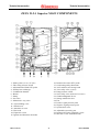
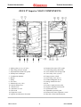
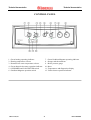
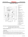
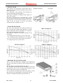
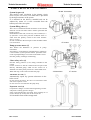
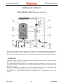
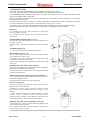
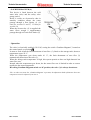
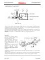
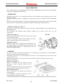
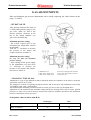
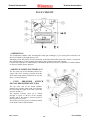
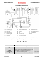
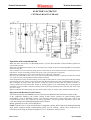
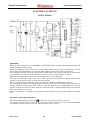
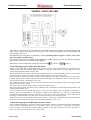
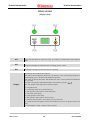
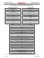
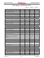
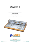
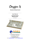
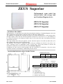
Technical documentation
Technical documentation
ZEUS Superior
Wall-mounted, room sealed fan
assisted boiler with storage tank
and Gaudium Magnum device
ZEUS 21 Superior
ZEUS 24 Superior
ZEUS 27 Superior
- GENERAL FEATURES
ZEUS Superior is a wall-hung room sealed fan-assisted boiler featuring a "Gaudium Magnum" device for
fully exploiting the characteristics of this 54 l boiler in AISI 316L stainless steel.
The appliance is regulated and controlled by means of a printed microprocessor control board which,
through a display, shows the state of boiler operation (temperature, safety devices, etc.) and enables it to
be connected (optional) to the Remote Friend Control, to the zones unit and to the Multisystem Water
Disconnector.(D.I.M.)
The range includes three electronic-ignition versions with heat outputs of 24.4 kW (21,000 kcal/h), 27.9
kW (24,000 kcal/h) and 31.4 kW (27,000 kcal/h).
The hydraulic circuit features a high-head copper water-gas exchanger, an electric 3-way valve, a 2 l
d.h.w. expansion vessel, an adjustable system by-pass and a device that permits to increase the
maximum available flow of the domestic hot water (Gaudium Magnum).
Combustion air flow into the sealed chamber and flue extraction are ensured by a fan, the correct
operation of which is controlled by a differential pressure switch.
- MAIN DIMENSIONS AND CONNECTIONS
DIMENSIONS (mm)
ZEUS 21/24/27
HEIGHT
WIDTH
DEPTH
900
600
450
ATTACCHI
GAS
ZEUS 21/24/27
SYSTEM
G
R
M
1/2 “
3/4 “
3/4 “
DOMESTIC
WATER
U
E
1/2 “ 1/2 “
V - electric connection
G - gas supply
R - system return
M - system delivery
S - recirculation (optional )
U - domestic hot water outlet
E - domestic cold water inlet
STZS ed 06/03
1
ZEUS SUPERIOR
Technical documentation
Technical documentation
ZEUS 21-24 Superior MAIN COMPONENTS
1 - Intake points (A=air) (F=flue)
2 - Flue safety pressure switch
3 - Adjustment and limit NTC probe
4 - Primary heat exchanger
5 - Combustion chamber
6 - Burner
7 - Pump
8 - Gas valve
9 - Motorized 3-way valve
10 - System filling valve
11- Sealed room
12- Automatic air vent
13- Flue hood
14- Expansion vessel
15- Ignition and detection electrodes
STZSC ed 06/03
16- Domestic hot water NTC probe
17- Overheating safety thermostat
18- 316L stainless steel storage tank
19- 3 bar safety valve (system)
20- Pump pressure switch
21- 8 bar safety valve (domestic hot water)
22- Gaudium Magnum device
23- Storage tank drain valve
24- Fan
25- Positive signal pressure point
26- Negative signal pressure point
27- System drain valve
28- Adjustable system by-pass
29- Domestic hot water expansion vessel
30- Max d.h.w. flow limit thermostat
2
ZEUS SUPERIOR
Technical documentation
Technical documentation
ZEUS 27 Superior MAIN COMPONENTS
16- Domestic hot water. NTC probe
17- Overheating safety thermostat
18- 316L stainless steel storage tank
19- 3 bar safety valve (system)
20- Pump pressure switch
21- 8 bar safety valve (d.h.w.)
22- Gaudium Magnum device
23- Storage tank drain valve
24- Fan
25- Positive signal pressure point
26- Negative signal pressure pointr
27- System drain valve
28- Adjustable system by-pass
29- Domestic hot water expansion vessel
30- Max d.h.w flow limit thermostat
1 - Intake points (A=air) (F=flue)
2 - Flue safety pressure switch
3 - Adjustment and limit NTC probe
4 - Primary heat exchanger
5 - Combustion chamber
6 - Burner
7 - Pump
8 - Gas valve
9 - Motorised 3-way valve
10- System filling valve
11- Sealed room
12- Automatic air vent
13- Flue hood
14- Expansion vessel
15- Ignition and detection electrodes
STZSC ed 06/03
3
ZEUS SUPERIOR
Technical documentation
Technical documentation
CONTROL PANEL
7 - Green Gaudium Magnum operating indicator
8 - Storage tank thermometer
9 - Boiler pressure gauge
10- Reset
11- Temperatures and diagnostics display
12- Yellow burner operation indicator
1 - Green heating operating indicator
2 - Heating temperature selector
3 - Domestic hot water temperature selector
4 - Green domestic hot water operation indicator
5 - 0/SUMMER and CAR/WINTER switch
6 - Gaudium Magnum operation switch
STZSC ed 06/03
4
ZEUS SUPERIOR
Technical documentation
Technical documentation
HYDRAULIC CIRCUIT
1 - Storage tank drain valve
2 - One way valve
3 - Coil
4 - Gas valve
5 - Magnesium anode
6 - Storage tank
7 - Pump
8 - Burner
9 - Combustion chamber
10- Primary heat exchanger
11- Flue hood
12- Fan
13- Flue safety pressure switch
14- Sealed room
15- Adjustment and limit NTC probe
16- Automatic air vent
17- Expansion vessel
18- Overheating safety thermostat
19- Pump pressure switch
20- Pump pressure meter
21- Domestic hot water. NTC probe
22- System drain valve.
23- Motorised 3-way valve
24- System filling valve
25- Adjustable system by-pass
26- 3 bar safety valve
27- D.h.w. expansion vessel
28- 8 bar d.h.w. safety valve
29- Gaudium Magnum device
30- Cold water inlet filter
31- Max flow limit thermostat
G – Gas supply
U – Domestic hot water outlet
E – Domestic cold water inlet
R – System return
M – System delivery
The hot water for the heating system and for the domestic circuit is produced by a primary circuit
and a secondary (domestic) circuit that are activated according to demand.
PRIMARY CIRCUIT (BOILER CIRCUIT)
The primary circuit with the relative control and safety devices is activated with each heating or
domestic circuit demand for water.
- OPERATION
The copper blades of the water-gas exchanger (10) absorb the heat contained in the flue gas
produced by combustion.
Those blades then transfer the heat to the water being circulated inside by the boiler pump (7).
The water is introduced directly into the plant or can be deviated inside the cylinder coil (3).
This depends on the position of the electric 3-way valve (23) which, depending on the demand,
allows water to flow through the plant delivery (M) and return (R) pipes or deviates it to the coil (3).
STZS ed 06/03
5
ZEUS SUPERIOR
Technical documentation
Technical documentation
- CIRCULATOR
This operates on the primary circuit return and is
located on the brass header assembly of the electric
three ways valve.
It is connected to the monobloc and exchanger by
means of threaded connecting pipes.
The pumps used differ according to boiler output (see
head - flow graph).
The body is equipped with a threaded fitting which
on the21 and 24 versions is used for the connection of
the expansion vessel and of the automatic vent valve,
while on the 27 version is used for the directly
connection of the automatic air vent.
21 and 24 versions
27 version
.
- FLOW HEAD GRAPH
The curve that represents the relation between the
flow rate and the available head depends on system
bypass adjustment which, depending on its position,
gives the system greater or less head.
The graphs are refereed to the pump operating at top
speed with:
- A = Bypass disconnected (screw fully tightened)
- B = Standard bypass adjustment (screw tightened
by 4.5 turns with respect to fully-tightened position)
- C = Bypass open (screw fully loose)
ZEUS 24 Superior
ZEUS 21 Superior
ZEUS 27 Superior
- PRIMARY HEAT EXCHANGER
This is a water-gas blade type exchanger with copper pipes
and fins at the outlet of which an NTC heating probe (5) is
located.
The size differs according to boiler heat output.
The four pipes passing through the exchanger are connected
in parallel (1) two by two, to reduce flow resistance to the
utmost and provide a greater available head.
It is connected to the pump flow and to the primary circuit
flow by means of coupling pipes (2) with O.R. seal (4).
These are secured by means of special forks (3).
STZS ed 06/03
6
ZEUS SUPERIOR
Technical documentation
Technical documentation
- SAFETY DEVICES AND CONTROLS
21 and 24 versions
System by-pass (6)
This ensures water circulation in the primary circuit
(between flow and return) even when this is prevented
by the high resistance of the system.
It is mounted on the delivery manifold and can be
adjusted by means of a screw accessible from the
bottom part of the valve plate.
System filling valve (5)
This valve is installed between the boiler circuit and the
domestic circuit cold water inlet is used to pressurize the
heating system.
Downstream of the cock, an one way valve is fitted (nr 2
of hydraulic circuit) that prevents accidental flow of
water from the primary circuit to the water network
(d.h.w. circuit).
Its seat is located in the lower part of the monobloc where
it is screwed on.
27 version
Pump pressure meter (2)
This detects the difference in pressure at pump
extremities.
Its housing is in the delivery manifold and is coupled to
a micro-switch (3) that prevents burner operation in the
event of pump blockage or no water in the boiler circuit.
Prevents primary exchanger overheating.
3-bar safety valve (4)
Prevents safety pressure (3 bar) being exceeded in the
circuit.
On the versions 21 and 24 is fitted to the rear part of the
delivery manifold group, while on the version 27 is
fastened in its front part by means of a socket head screw.
When this trips, water exits from the flow pipe.
21-24versions
27 version
Automatic air vent (7)
Automatically expels any gaseous substances in the
boiler circuit.
On the versions 21 and 24 , the valve is screwed on the water
side of the expansion vessel.
On the version 27 is mounted on the pump body.
Expansion vessel (8)
Compensates changes in volume following heating of water
and permits reducing pressure changes.
It has a pre-load pressure of 0.8 bar and a capacity of 8 l
on the versions 21-24 and 10 l on the version 27.
It is located in front of the storage tank .
STZS ed 06/03
7
ZEUS SUPERIOR
Technical documentation
Technical documentation
HYDRAULIC CIRCUIT
SECONDARY CIRCUIT (D.H.W. CIRCUIT)
The domestic hot water circuit is engaged every time the water contained in the storage tank and
measured by means of the d.h.w. NTC sensor (4) has to be restored to the desired temperature.
This occurs when domestic hot water is used and to restore the losses due to thermal dispersion.
- OPERATION
Following a d.h.w. request, the modulation board starts the boiler pump (7) and powers the
motor of the electric 3-way valve (8).
The consequent movement of the valve to domestic hot water position (see 3-way electric valve
operation), closes the system return pipe (R) and, at the same time, opens the return pipe of the
storage tank coil (4).
This way, circulation is allowed in the coil (4) which, through its walls, enables the cold
domestic water to absorb the heat contained in the primary circuit water.
In this phase, the central heating function is disconnected as the production of d.h.w. has
priority.
STZS ed 06/03
8
ZEUS SUPERIOR
Technical documentation
Technical documentation
- STORAGE TANK
This AISI 316L STAINLESS STEEL storage tank has a useful capacity of 60 l.
It consists of an external sleeve enclosed at the bottom by a flange fixed by 12 screws.
A STAINLESS STEEL cylindrical pipe with a concentric spiral shape (coil) is inserted inside and is coiled
along all the height of the storage tank.
Heat is exchanged between the hot water in the primary circuit and the water contained in the cylinder
through the walls of the coil.
This keeps the water in the cylinder at a constant temperature and guarantees instant availability of domestic
hot water on demand (21.000, 24.000 e 27.000 kcal/h according to the versions).
If necessary, the coil can be removed from the storage tank after taking off the lower inspection flange.
The following devices ensure that it operates correctly and is maintained in good condition:
Anode (1)
It is inserted in the storage tank and protects it against the
action of galvanic currents.
It is screwed onto the external sleeve at the bottom of the
storage tank.
Polyphosphate metering unit (optional)
This prevents any limestone deposits from accumulating on
the walls of the coil.
The special kit is mounted on the domestic cold water circuit
inlet.
Gaudium Magnum (6)
(see description and operation Gaudium Magnum)
Recirculation kit (optional)
This is used to connect the pipes of any recirculation system
of the domestic hot water circuit.
It consists of a pipe that is inserted into the tank after having
removed the anode with relative plug.
When the kit is installed, the anode must be screwed to the end
of the pipe.
Domestic hot water NTC sensor (NB) (9)
This allows the printed control board to detect the temperature
of the water contained in the storage tank.
It is attached to the external wall of the storage and inserted
inside an immersion trap.
Maximum flow d.h.w limit temperature thermostat (3)
It is a clicson thermostat which supplies the solenoid valve of
the Gaudium Magnum device.
It is fitted on the external wall of the storage tank.
Safety valve unit (13)
This unit is located in the lower part of the cylinder near the
domestic circuit cold water inlet.
In addition to an 8-bar valve (10) that prevents the safety
pressure from being exceeded inside the storage, it also
includes:
- a filter, a cylinder drain valve with hose fitting (12) and a
one-way valve (“5” domestic circuit) to prevent a pressure
increase following heating of the domestic circuit hot water
from causing water to return toward the water mains.
Domestic hot water circuit expansion vessel (11)
It compensates for volume variations following heating of the
water contained in the cylinder.
It is connected to the safety valve unit and has a capacity of 2 l
at a pre-load pressure of 3.5 bar.
STZS ed 06/03
9
ZEUS SUPERIOR
Technical documentation
Technical documentation
- GAUDIUM MAGNUM (6)
This device is fitted between the cold
water inlet (inlet) and the safety valve
group (outlet).
Inside it works an electrovalve that in
stand-by condition allows the water
passage through a flow limiter (1) (10
l/min for versions 21 and 27, 12 l/min for
version 24)
When the electrovalve (3) is supplied the
water flows trough a supplementary
passage through a 6 l/min flow limiter (2)
- Operation
The valve is electrically enabled (230 VAC) setting the switch “Gaudium Magnum”, located on
the control panel, on position .
It starts to work when the limit thermostat of max flow (3), fitted on the storage tank, detects a
temperature upper 50 °C.
When the temperature gets down under 41 °C, the limit thermostat of max flow (3)
automatically deactivates the valve (3).
When the storage tank temperature is high, this system permits to have an high domestic hot
water flow rate.
Instead when the temperature gets down, the hot water flow rate is limited in order to restore
rapidly the hot water temperature.
Re-setting Gaudium Magnum switch on “0” position, the valve (3) is always deactivates.
N.B.: in order to activate the “Gaudium Magnum” operation, the adjustment knob of domestic hot water
temperature must be adjusted from 6 to 9.
STZS ed 06/03
10
ZEUS SUPERIOR
Technical documentation
Technical documentation
- MOTORIZED 3-WAY VALVE
This is a 3-way electric valve operating on the return pipe of the primary circuit that permits,
according to the type of request (domestic hot water or central heating), running boiler water into
the central heating system or into the storage tank coil
This depends on the position of the shutter (3) which impedes transit towards the system and at the
same time permits this towards the storage tank (d.h.w. position) or vice versa (central- heating
position).
Movement of the shutter (3) in both positions is achieved by energizing the motor (1).
Operation
To move to the heating or domestic
hot water circuit, the motor (1) is
activated by the control card.
Activating the motor, whose rpm is
reduced by a special gear system,
begins rotating a disc (6) with an
eccentric connection on the shaft of
that motor.
The moving disc activates a special
coupling (5) that, with each 180°
rotation,
compresses
(heating
position) or releases (domestic circuit
position) the plug valve contrast
spring (4).
Hydraulically reaching the requested position causes first one limit switch (2) to open and then
another to close.
This allows the voltage to be cut off to the motor, freezing it in the position reached and enabling
motor operation only when a different request (domestic circuit or heating signal) is received.
STZS ed 06/03
11
ZEUS SUPERIOR
Technical documentation
Technical documentation
GAS CIRCUIT
The circuit consists of an atmospheric burner and a modulating type valve for gas combustion
and gas flow adjustment respectively.
- OPERATION
When the main coils (3) are energized, both inner valve shutters open, allowing the gas to flow
towards the burner.
The flow rate/outlet pressure is regulated by means of the gas valve stabilizer and the modulation
coil.
By means of the burner nozzles (7), the fuel is injected into the venturi pipes (ramps) inside which
the air-gas mix is obtained that is ignited by the spark from the ignition electrodes (5).
- MODULATING GAS VALVE
The gas valve (SIT 845) features two main coils and a third modulation coil controlled by the
adjustment board.
The maximum and minimum outlet pressure settings can be made on this valve (see gas
adjustments).
Main electric coils (3)
These two ON-OFF coils are fed (230 Vac) by the control
card to ignite the burner.
They are electrically connected in parallel and fed by
mains voltage through a special connector (2).
SIT 845
Modulation coil (1)
This low-voltage coil is controlled by the modulation card.
It controls the gas valve stabilizer and can be used to vary
the outlet pressure so that it is proportional to the d.c.
signal conveyed through it.
- BURNER
The burner consists of horizontal venturi pipes (6) in which the gas is injected by an equal number of
nozzles (7) mounted on the special header (8).
The number of nozzles is 13 in the 21,000 kcal/h version, 15 in the 24,000 kcal/h version and 16 in the
27,000 kcal/h version .
Ignition occurs by means of an electronic board (unit) which controls the ignition electrode (5) and
detection electrode (4).
Ignition electrodes (5)
They are controlled by the ignition unit that
generates an electric discharge between the two
electrodes.
They are mounted on the front of the burner between
the first and the second gas ramp (Venturi tube).
Detection electrode (4)
This is controlled by the ignition unit and detects
burner ignition.
It is positioned on the front of the burner on the
ramp alongside the ignition electrodes.
STZS ed 06/03
12
ZEUS SUPERIOR
Technical documentation
Technical documentation
GAS ADJUSTMENTS
Max and minimum gas pressure adjustments can be made respecting the values shown on the
page’s 31 and 32.
- SIT 845 VALVE
After having connected the leads of
a differential pressure gauge to the
gas valve outlet (4) and to the
positive pressure connector at the
top of the sealed chamber (see
figure), do the following :
Maximum pressure setting
- Do a d.h.w. request (open a tap)
and setting the temperature selector
at maximum.
Turn nut “3” clockwise to increase
the pressure to the burner and
counter-clockwise to reduce it.
Minimum pressure setting
(to carry out after the maximum
pressure setting)
- After cutting off the power supply
to the modulation coil, turn screw
“2” clockwise to increase the
pressure to the burner and counterclockwise to reduce it.
1) Modulation coil
2) Min. power setting screw
3) Max. power setting screw
4) Gas valve outlet pressure connector
5) Gas valve inlet pressure connector
6) Protective cap
- CHANGING TYPE OF GAS
Adaptation to a type of gas different to that for which the boilers are intended, can be done by using the
special kits (natural gas or LPG).
The changeover consists in replacing the burner nozzles and in moving to the modulation board of the
“NATURAL GAS- LPG” (CM3) bridge.
The minimum and maximum pressures are then set on the gas valve in the way described above.
Adjustment of the minimum and maximum output during the heating phase and of burner ignition
pressure (see table below) can be done by means of the respective trimmers mounted on the modulation
board (see modulation board operation).
Soft ignition values in mbar (mm H2O)
Natural gas
LPG
ZEUS 21/24 Superior
25
65
ZEUS 27 Superior
23
70
STZS ed 06/03
13
ZEUS SUPERIOR
Technical documentation
Technical documentation
FLUE CIRCUIT
- OPERATION
The combustion residues, after investing the water-gas exchanger (1), are conveyed to a hood (3) at
the top of which is a draught diverter (4).
Operation of the fan ensures forced extraction of the flues and at the same time creates a vacuum in
the sealed chamber (2) that permits extraction of the combustion air from outside.
Correct flue extraction is controlled by a differential pressure switch (5), operation of which enables
or does not enable burner ignition.
- AIR/FLUE SAMPLING TRAPS (6-7)
The top outer part of the chamber features two
sumps with screw closing accessible from the
front and through which combustion air (6) and
flues (7) can be extracted.
FLUE
PRESSURE
SWITCH
SIGNAL PRESSURE POINT (8-9)
The top outer part of the sealed chamber
features two pressure points with screw closing
for measuring the signal at the ends of the flue
pressure switch (5).
The negative pressure point (8) is linked
through a Y-pipe to the top of the draught
diverter and to the negative pressure point of
the flue pressure switch.
The positive pressure point (9) is directly linked
to the inside of the sealed chamber.
STZS ed 06/03
14
ZEUS SUPERIOR
Technical documentation
Technical documentation
- FLUE PRESSURE SWITCH (5)
This is positioned in the top inner part of the sealed chamber and, by means of the points provided, reads
the difference in pressure between the top of the draught diverter (the point where the extractor is
positioned and operates) and the inside of the sealed chamber.
The signal measured from the pressure switch varies according to the length of the extraction/exhaust
terminals and is measured by the special pressure points fitted to the top part of the sealed chamber (8-9).
Its operation causes a deviation of a switch contact that acts on the unit (IGN. UNIT) and enables or fails
to enable burner ignition.
- FAN (4)
The extractor operates downstream of the combustion chamber and is physically "rested" on the top part
of the hood (3) from which it extracts fumes into the exhaust pipes to which the boiler is linked.
It is controlled from the ignition unit and its operation coincides with that of the boiler.
The fans used differ according to the output of the appliance (21,000, 24,000 and 27,000 kcal/h).
STZS ed 06/03
15
ZEUS SUPERIOR
Technical documentation
Technical documentation
EXTRACTION AND EXHAUST SYSTEMS
(see extraction and exhaust end instructions )
ZEUS Superior is prearranged for connection to the special coupling type extraction and exhaust pipes.
- EXHAUST
Connection to the exhaust pipes is done by means of a
flange (1) or a flanged curve to be fastened to the union
(4) on the top part of the sealed chamber after placing in
between a special shaped seal (6).
The flange differs according to whether the doubled or
concentric system is used. In the first case, the opening
for extraction of combustion air (5) is closed, while in the
latter case, this is used.
For correct boiler operation, a diaphragm (7) must be
fitted on the exhaust (4) in between the flange used (1).
Diaphragms of different diameter are available which
must be fitted according to the type of pipe and its length
(see boiler instruction booklet).
- EXTRACTION
Using the doubled system, connection to the extraction
pipes is done in the same way as the exhaust pipes, by
connecting up to the 80 mm diameter hole on the top part
of the sealed chamber.
The hole is normally closed by means of a special cap (2)
equipping the boilers.
If coaxial pipes are used, extraction is done through the concentric hole outside the exhaust pipe (5).
- EXTRACTION EXHAUST KIT
The kits and relevant accessories make it possible to use four concentric systems and two doubled systems.
As regards pressure drop relating to each accessory, the various possible combinations and the use of the
diaphragms to be fitted according to the length of the pipes, see the instructions concerning the extraction and
exhaust ends (boiler instruction booklet). The accessories (curves, extensions and end pieces) are of the coupling
type and seal is provided by special lip seals.
Coupling type horizontal concentric kit 60 /100
The exhaust pipe (φ 60 mm) is fitted inside the extraction
pipe (φ 100 mm).
Connection to the boiler is made using a 90° curve (1)
that can be positioned in any direction and which, by
means of the necessary extensions, must be connected to
the special extraction and exhaust end (2).
Max possible overall length beyond the first curve (1) is
3 straight and horizontal metres.
Coupling type horizontal concentric kit 80 /125
The exhaust pipe (φ 80 mm) is fitted inside the extraction
pipe (φ 125 mm).
Connection to the boiler is made using a 90° curve
diameter 60/100 (1) that can be positioned in any
direction and which, by means of the adapter 60/10080/125 (2) and necessary extensions, must be connected
to the special extraction and exhaust end (3).
Max possible overall length beyond the first curve (1) is
7.3 straight and horizontal metres.
STZS ed 06/03
16
ZEUS SUPERIOR
Technical documentation
Technical documentation
Coupling type vertical concentric kit 60 /100
The exhaust pipe (φ 60 mm) is fitted inside the
extraction pipe (φ 100 mm).
Connection to the boiler is made using a flange (1)
that, by means of the necessary extensions, must be
connected to the special 60/100 extraction and exhaust
end with aluminium tile.
Max possible overall length is 4.7 straight and
vertical metres.
Coupling type vertical concentric kit 80 /125
The exhaust pipe (φ 80 mm) is fitted inside the
extraction pipe (φ 125 mm).
Connection to the boiler is made using a flange (1)
that, by means of the adapter 60/100-80/125 (3) and
necessary extensions, must be connected to the special
80/125 extraction and exhaust end with aluminium tile
(2).
Max possible overall length is 12.2 straight and
vertical metres.
80/80 coupling type separator kit
Both pipes have a diameter of 80 mm.
Connections to the boiler are made using two special
flanges for exhaust (1) from the centre pipe and
extraction (2) from the side hole.
Max possible length (extraction + exhaust) is 33
straight horizontal metres and 41 straight
vertical metres.
To prevent condensation problems, the exhaust pipe
should not be more than 5 m long
Insulated 80/80 coupling type separator kit
Both pipes have a working diameter of 80 mm.
Connections to the boiler are made using two special
flanges for exhaust (1) from the centre pipe and
extraction (2) from the side hole.
Insulation is obtained thanks to special seals (3)
whereby an air space can be created by means of a φ
125 mm external concentric pipe.
Max possible length (extraction + exhaust) is 33
straight metres.
To prevent condensation problems, the exhaust pipe
should not be more than 12 m long
STEM ed 05/99
17
EXTRA MINI
Technical documentation
Technical documentation
ELECTRICAL CIRCUIT
CAR
CZ
DL1
DL2
DL3
E1/E2
E3
EP
F
IG
Remote control
Control xone unitt
Central heating operation LED
D.h.w. operation LED
Flame LED
Ignition electrodes
Detection electrode
Gaudium Magnum solenoid valve
Fuse
Main switch
IP
LP
Gaudium Magnum switch
Gaudium Magnum operating
indicator
MOD Modulation coil
MP
Circulator
MV Fan
NB
D.h.w. NTC sensor
NE
External sensor (optional)
NR
Central heating NTC sensor
P1
Room thermostat jumper
PU1 Reset button
SP
Pump pressure switch
SV
Flue pressure switch
TA
Room thermostat
TP
Max flow limit thermostat
TS
Overheat. safety
thermostat
VD
Electric three-way valve
V/G Gas valve
The electric circuit is interlocked with a microprocessor electronic board that controls boiler functions.
The control and safety devices work in part at mains voltage and in part at low voltage.
230 V AC CIRCUIT
SAFETY DEVICES AND CONTROLS
Detection electrode (E3)
Fuse
“Gaudium
Magnum” switch
(IP)
STZS ed 06/03
This detects ignition of the burner by whose flame it is invested.
It is connected to the detection circuit of the ignition unit.
This interrupts power to the circuit when amp draw is over 3.15 A.
It is fitted on the modulation board.
Fuse
3.15 A 250 V
Enables the operation of the Gaudium Magnum solenoid valve (EP),
which is supplied by the maximum flow limit thermostat (TP).
0
- solenoid valve closed (not supplied)
2-contacts switch
- solenoid valve enabled (supplied by the closing of the
maximum flow limit thermsostat switch) (TP)
18
ZEUS SUPERIOR
Technical documentation
Main switch
(IG)
Max flow limit thermostat
(TP)
Overheat. safety device
(TS)
Technical documentation
0
Depending on position, this allows:
- circuit not powered
3-position switch
- d.h.w. and CAR function (optional)
- d.h.w. and central heating function.
It is screw up on the external wall of the storage tank.
With the Gaudium Magnum switch (IP) in
position, powers the Clicson doublesolenoid valve of the Gaudium Magnum device (EP) when measures a contact thermostat
temperature higher than 50 ºC.
Interrupts electrical supply when the temperature falls below 41 ºC.
When the safety temperature (100 ºC) is exceeded, this interrupts power
to the main coils of the gas valve.
It is positioned on the flow pipe at the primary exchanger outlet.
Clicson doublecontact
thermostat
LOADS
3-way electric valve
(VD)
Circulator
(MP)
Fan (MV)
Gas valve (V/G)
(main coils)
“Gaudium Magnum”
electro valve
(EP)
“Gaudium Magnum” (LP)
operating indicator
Ignition control unit
(IGN. UNIT)
Deviates the flow of water of the primary circuit from the heating circuit to the boiler coil
and vice versa.
It is powered by the modulation board.
Permits circulation of water in the primary circuit.
This is powered by the modulation board whenever there is a demand for d.h.w.,
heating or antifreeze.
Ensures the flow of air inside the sealed combustion chamber and the exit of flues produced
by combustion.
Powered by the modulation board.
This is powered by the ignition control unit when the burner has to be ignited.
Permits flow of gas to the burner.
Permits to increase the maximum available flow of domestic hot water (see Gaudium
Magnum operation).
Powered when the “Gaudium Magnum (IP) is in
limit thermostat (TP)
position and by the maximum flow
Displays on the control panel the operation of the “Gaudium Magnum” function..
Is a green lamp connected in parallel to the “Gaudium Magnum” solenoid valve(EP).
Controlled by the modulation board when the burner has to be ignited.
Controls the devices needed for ignition (gas valve, ignition electrodes) and flame detection
(ionisation electrode).
Ignition electrodes
(E1 - E2)
These provoke an electric spark that ignites the air/gas mix.
They are controlled by the control unit ignition transformer (IGN. BOARD)
Modulation board
This is powered when the main switch (IG) is positioned in
(winter) (see modulation board operation).
STZS ed. 06/03
19
(summer or CAR) or
ZEUS SUPERIOR
Technical documentation
Technical documentation
LOW-VOLTAGE CIRCUIT
SAFETY DEVICES AND CONTROLS
Central-heating sensor
(NR)
Allows the modulation board to detect the temperature of the primary
circuit water flow.
If this sensor stops working, burner operation stops both in centralheating and d.h.w. modes.
It is positioned at the outlet of the main exchanger.
Control zone unit (CZ)
(external optional)
Permits boiler operation with 3 area valves /external pumps controlled
See control unit
by respective room thermostats.
zone operation
Zone 1 is controlled (times/temperatures) by means of the CAR (if
fitted).
Domestic hot water sensor
(NB)
This enables the modulation board to detect the temperature of the hot
water in the storage tank.
Its failure stops burner operation in domestic hot water phase.
Sensor NTC
10 kohm 25 ºC
Sensor NTC
10 kohm 25 ºC
It is inserted inside a bulb holder in contact with the external wall of
the cylinder.
External sensor (NE)
(external optional)
Detects external temperature and enables the modulation board to
change the system flow temperature according to outside temperature.
Sensor PTC
1 kohm 25 ºC
Flue pressure switch
(SV)
This acts on the modulation board and enables burner operation when
flue expulsion occurs correctly.
If this is closed with the fan off, the ignition cycle will not start.
2-position switch
Pump pressure switch
(SP)
This acts on the modulation board and permits interrupting power to
the control unit in the event of there being no circulation in the boiler
circuit.
Double-contact
switch
Remote control (CAR)
(external optional)
Permits remote control of boiler iSUM/WINT switch, temperature
adjustment and indication, alarm display, reset, etc.) and acts as a
weekly chrono-thermostat.
Together with the external sensor (NE), allows the modulation board to
change the system flow temperature according to need.
See Remote
Friend Control
operation (CAR)
Room thermostat (TA)
(external optional)
This enables operation in central heating phase when the room
temperature is below that required.
In case of CAR installation, the room thermostat must be disconnected
without resetting the pre-existing jumper P1.
Double cleancontact switch
LOADS
Display board
Modulation coil (MOD)
STZS ed. 06/03
This displays burner operation (orange LED), operation in d.h.w. phase (green LED) and in
central-heating or antifreeze phase (green LED) on the control panel.
By means of a dispaly, it indicates the temperature of the boiler, the temperatures set for
d.h.w. and central-heating and the error codes (see modulation board operation).
This is powered by the modulation board with variable direct current.
It permits changing gas pressure to the burner.
20
ZEUS SUPERIOR
Technical documentation
Technical documentation
ELECTRICAL CIRCUIT
CENTRAL-HEATING PHASE
Operation with room thermostat
When the mainr switch (IG) is in WINTER position, it powers the modulation card and enables operation in
central heating mode.
When the room thermostat contact (TA) is closed, the low-voltage circuit starts the pump (MP) by closing the
contact of relay K2.
The circulation of water causes the pump pressure switch (SP) to close and, because this is connected in series
with the NC contact of the flue pressure switch (SV), the coil of relay K5 is energised.
Meanwhile, the adjustment circuit causes the deviation of the relay contact K3.
This way, the motor (M) of the 3-way valve (VD) is powered and continues to operate until the limit switch
"N" opens once the central heating position has been reached.
If the temperature read by the NTC heating sensor (NR) is below that set on the control panel with the heating
potentiometer, the low-voltage circuit excites the relay K5 and starts the fan (MV) commanding the relay K1.
The consequent deviation of the flue pressure switch (SV) powers the relay K4 the contact of which, on
closing, enables the control unit (IGN. UNIT) to start the ignition cycle, commanding first of all the ignition
electrodes (E1-E2) and then, with the consensus of the overheating thermostat (TS), both the main coils of the
gas valve (V/G).
Ignition of the burner is detected by the control unit (IGN. UNIT) by means of the ionisation electrode (E3).
Operation with Remote Friend Control
The main switch (IG) in SUMMER position powers the modulation board and remote control (CAR).
If the conditions found by the remote control (CAR) require ignition in central heating phase
(SUM/WINT switch in WINTER position, central-heating temperature setting above that read by the
central-heating sensor NR, request by the time programmer, room temperature adjustment above that
read), the board powers pump MP through relay K2 contact.
Burner ignition then occurs as described above.
NOTE: In both cases, at each switch-off due to temperature having been reached, the modulation board
stops burner operation during central-heating phase for 180 seconds., which can be reduced to 30
seconds by intervening on the special jumper (J1) (see modulation card operation).
STZS ed. 06/03
21
ZEUS SUPERIOR
Technical documentation
Technical documentation
ELECTRICAL CIRCUIT
D.H.W. PHASE
Operation
When the main switch (IG) is in SUMMER or WINTER position, it powers the modulation board and
enables operation in d.h.w. mode.
When the temperature read by NTC d.h.w. sensor (NB) is below that set on the control panel (or on the
CAR if fitted), the adjustment circuit starts the pump (MP) by means of the contact of relay K2.
The circulation of water causes the pump pressure switch (SP) to close and, because this is connected in
series with the NC contact of the flue pressure switch (SV), the coil of relay K5 is energised.
Meanwhile, the adjustment circuit causes the deviation of the relay contact K3.
This way, the motor (M) of the 3-way valve (VD) is powered and continues to operate until the limit
switch "A" opens once the d.h.w. position has been reached.
The low-voltage circuit excites the relay K5 and starts the fan (MV) commanding the relay K1.
The consequent deviation of the flue pressure switch (SV) powers the relay K4 the contact of which, on
closing, enables the control unit (IGN. UNIT) to start the ignition cycle, commanding first of all the
ignition electrodes (E1-E2) and then, with the consensus of the overheating thermostat (TS), both the
main coils of the gas valve (V/G).
Ignition of the burner is detected by the control unit (IGN. UNIT) by means of the ionisation electrode
(E3).
Operation with Gaudium Magnum”
When the Gaudium Magnum switch is in
position, the contact of the switch “IP” is closed.
The solenoid valve EP and the lamp LP are powered when the main switch (IG) is “ON” position (SUMMER
or WINTER) and the max d.h.w. flow limit (TP) thermostat switch is closed.
STZS ed. 06/03
22
ZEUS SUPERIOR
Technical documentation
Technical documentation
MODULATION BOARD
The boiler is equipped with a microprocessor-controlled electronic board used on both the models with
3-way electric valve (Zeus Superior, Eolo Superior Plus) and on the models with central-heating and
d.h.w. pumps (Hercules).
The different type of operation is obtained by adjusting diode D9 (diode engaged = electric 3-way valve,
diode disengaged = double pump).
The board is connected to a terminal board (DISPLAY CARD) which, by means of LEDs and a display
panel, indicates the state of operation of the appliance.
(summer) or
(winter).
The board is powered with main switch (IG) in position
Central-heating request with room thermostat
With the main switch (IG) in WINTER position and the contact of the room thermostat (TA) closed, the lowvoltage circuit starts the circulator (MP) by means of relay “K2” and powers the motor (M) of the 3-way
valve (VD) through the contact of relay “K3”.
The circulation of water results in the closing of the pump pressure switch (SP) which, because it is connected
in series to the NC contact of the flue pressure switch (SV) powers the coil of relay “K5”.
If the temperature detected by means of NTC central heating sensor (NR) is below that set on the control
panel by means of the central heating potentiometer (HEATING), the adjustment circuit excites relay “K5”
and starts the fan (MV) controlled by relay “K1”.
The consequent deviation of the contact of the flue pressure switch (SV) results in relay “K4” being powered
and the relevant contact closing.
This powers the control unit (IGN. UNIT) and starts the ignition cycle.
During the ignition phase, the current to the modulation coil is restricted by the adjustment made with the soft
ignition trimmer (POT ACC.).
Once the flame has been detected (signal from control unit), the signal to the coil (MOD) is changed in a
manner directly proportionate to the difference between the temperature set with the central-heating
potentiometer (HEATING) and that detected by means of the NTC central-heating sensor (NR) and, if
necessary, reaches maximum set value in 50 seconds (maximum central-heating output).
When the set value is exceeded, the contact of relay “RT” is opened with consequent switch-off of the burner.
Re-ignition of the burner for the same request remains inhibited for 180 s / 30 s.
Central-heating request with Remote Friend Control
If the conditions detected by the remote control (CAR) require ignition in central-heating phase (SUM/WINT
switch of CAR in WINTER position, time programmer request, room temperature setting above that found),
the low-voltage circuit starts the circulator (MP) by means of relay K2 and powers the motor (M) of the 3way valve (VD) by means of the contact of relay “K3”.
STZS ed. 06/03
23
ZEUS SUPERIOR
Technical documentation
Technical documentation
The circulation of water results in the closing of the pump pressure switch (SP) which, because it is connected
in series to the NC contact of the flue pressure switch (SV) powers the coil of relay “K5”.
If the temperature detected by means of NTC central-heating sensor (NR) is below that set by means of
the central heating potentiometer of the remote control (CAR), the adjustment circuit excites relay “K5”
and starts the fan (MV) controlled by relay “K1”.
The consequent deviation of the contact of the flue pressure switch (SV) results in relay “K4” being
powered and the relevant contact closing.
This powers the control unit (IGN. UNIT) and starts the ignition cycle, which continues in the same way
as the central-heating request with room thermostat.
Once the flame has been detected, the signal to the modulation coil is changed in a manner directly
proportionate to the difference between the boiler and room temperatures set and detected and, if
necessary, reaches maximum set value in 50 seconds (maximum central-heating output).
When the set value is exceeded, the contact of relay “RT” is opened with consequent switch-off of the
burner.
Re-ignition of the burner for the same request remains inhibited for 180 s / 30 s.
Domestic hot water request
If the temperature read by the NTC sensor on the storage tank (NB) is below that set by means of the
d.h.w. potentiometer (D.H.W.), the low-voltage circuit starts the pump (MP) by means of relay “K2 and
powers the motor (M) of the 3-way valve (VD) through contact of relay “K3”.
Following consequent closing of pump (SP) pressure microswitch, burner ignition proceeds in the same
way as for central-heating phase.
Flame modulation occurs with reference to the flow temperature read by the central-heating sensor (NR)
which is changed according to the difference between the temperature set by means of the d.h.w.
potentiometer (D.H.W.) and that measured by the d.h.w. sensor (NB).
When the temperature measured by the d.h.w. sensor (NB) exceeds that requested, the contact of relay
K4 is opened and after post-operation times also the contacts of relays “K2” (pump) and “K1” (fan).
When the temperature drops again, the relays are once again powered to start the new ignition cycle.
If, during operation, the heating sensor. (NR) measures a flow temperature higher than 87 ºC, the contact
of relay K4is opened. This is closed again just as soon as the temperature drops to 75 ºC.
Central-heating antifreeze request
With the main switch (IG) in SUMMER or WINTER position, if the temperature read by the NTC centralheating sensor falls below 4 ºC, the board allows ignition in central-heating mode and keeps the boiler
operating with the burner at minimum output until a boiler temperature of 42°C is reached.
Domestic hot water request
With the main switch (IG) in SUMMER or WINTER position, if the temperature read by the NTC d.h.w.
sensor (NB) falls below 4 ºC, the board allows ignition in d.h.w. mode and keeps the boiler operating with the
burner at minimum output until the d.h.w. (NB) sensor reads a temperature of 8°C.
During operation, the water in the primary circuit remains below 42°C because when such temperature is
reached, the board switches off the burner.
“Chimneysweep” request
When the reset button (PU1) is pressed for at least 10 seconds, as soon as this is released, the board gives the
signal for boiler ignition and keeps this operating in central-heating mode at max heating output for 15
minutes.
In this phase, only the limit thermostat function is operative (90 ºC) performed by the central-heating sensor.
The function is only engaged if there are no requests under way for central-heating, domestic hot water or
antifreeze and it is indicated by means of code "7" on the display panel and by the flashing of central-heating
(DL1) and d.h.w. (DL2) LEDs.
It can be interrupted by cutting power to the circuit.
STZS ed. 06/03
24
ZEUS SUPERIOR
Technical documentation
Technical documentation
INPUTS
Central-heating sensor
(NR)
This is a resistance that varies in a way inversely proportionate to the
temperature of the water flow in the primary circuit.
It is used as a limit thermostat (90 ºC).
D.h.w. sensor
(NB)
This is a resistance that varies in a way inversely proportionate to the
temperature of the water contained in the storage tank.
Sensor NTC
10 kohm 25 ºC
External sensor (NE)
(external optional)
This is a resistance that varies proportionately to the outside
temperature.
It enables the modulation board to change the system flow
temperatures in accordance with the outside temperature.
1 kohm 25 ºC
Flame detection
(FLAME)
10 kohm 25 ºC
Sensor PTC
This is a signal from the ignition card indicating the flame has been detected.
It enables the board to increase power to the modulation coil after restricting this during the
ignition phase.
Flame lock
This is a signal from the control unit (IGN. UNIT) that indicates burner
ignition failure.
The alarm is displayed with an error code on the display board display
panel (E01) or, if fitted, on the remote control (see CAR operation.).
Flue pressure switch (SV)
This enables burner ignition by powering the relay “K4” when flue
extraction occurs correctly.
If the "NO" contact is closed with fan off will fail to enable the start of
the ignition cycle.
Main switch
(IG)
Sensor NTC
230 Vac = flame
lock
0 Vac = stand-by
/ burner ON
2-position switch
Indicates whether d.h.w. operation mode (SUMMER) or d.h.w. and closed=WINTER
central-heating mode (WINTER) are enabled.
open = SUMMER
Overheating lock
(IC1)
This is a signal which, through an optoinsulator, indicates input to the
main coils of gas valve (V/G).
This permits the board to pinpoint and indicate with an error code
(E02) any operation of the safety overheat. thermostat (TS).
Pump pressure switch
(SP)
In case of locked pump or low pressure in the primary circuit, this
does not enable burner ignition and interrupts power to relays “K4”
and “K5”.
Remote control (CAR)
(external optional)
This sends SUM/WINT switch signals to the board relating to d.h.w. and central-heating
temperature adjustment and central heating request (time ,room temperature).
When the CAR is fitted, the room thermostat must be disconnected without restoring the
pre-existing jumper P1.
(see CAR operation)
Reset button
(PU1)
When this is pressed, the circuit is released after the overheating and
no-ignition safety device has tripped (100 ºC).
If this is kept pressed during operation, the gas pressure is maintained
at soft ignition level.
If this is kept pressed for at least 10 seconds in the absence of any
requests, when it is released the "chimneysweep" function is engaged.
230 Vac = coils
powered
0 Vac = coils not
powered
Double-contact
switch
Double-contact
button
Room thermostat (TA)
(external optional)
This is a clean-contact switch that enables operation in central-heating open = heating OFF
closed = heating ON
phase, when the room temperature is below that requested.
Zone control unit (CZ)
(optional)
This sends signals to the board relating to operation requests for any connected zone valves
/ external pumps (see control zone unit operation).
STZS ed. 06/03
25
ZEUS SUPERIOR
Technical documentation
Technical documentation
OUTPUTS
3-way valve relay (K3)
This relay permits powering the motor of the 3-way electric valve (VD).
It is excited by a central-heating request and remains idle with a d.h.w. request.
Control zone unit (CZ)
(optional )
This signal enables the control zone unit to know the operating condition of the appliance
(d.h.w./heating) and, if fitted, to recognise the CAR as area 1 room thermostat (see control
zone unit operation).
Fan relay (K1)
This single-pole relay commands the fan (MV) which is excited when operation is
required.
Modulation coil (MOD)
This is a D.C. signal that commands the modulation coil of the gas valve.
Permits changing the pressure of the gas to the burner.
Pump relay (K2)
This is a single-pole relay that powers the circulator (MP) and which is excited when
operation is required.
Remote control (CAR)
(external optional)
This signal permits displaying on the remote control panel the boiler temperature, operation
in d.h.w. or central-heating modes, the codes of the alarms that have tripped and the
temperature read by any external probe.
(see CAR operation)
Request relay (K4)
Reset
This is a single-pole relay that is excited when the burner has to be ignited.
By means of its contact, the ignition control unit is commanded (IGN. BOARD).
This signal releases the ignition control unit after the overheating or ignition failure safety
devices have tripped.
The operation is performed on the boiler control panel by means of reset button PU1 or, if
fitted, on the remote control panel (see CAR operation).
ADJUSTMENTS
C.-heating potentiometer
(HEATING)
Central-heating timing
(J1)
D.h.w. potentiometer
(D-H-W.)
Permits setting the temperature of the water for central-heating use between 38ºC and 85
ºC.
At each switch-off due to temperature being reached during centralheating, a delay is engaged of 3 min / 30 s until the next re-ignition for
the same type of request.
absent = 30 s
present = 3 min
Permits setting the temperature of d.h.w. between 20 ºC and 60 ºC.
Gas selector (CM3)
Depending on the position (natural gas/LPG), adapts the modulation parameters
to the gas for which the boiler is set.
Heating power trimmer
(HEATING POWER)
Permits regulating the output during heating phase and adapting this to the needs of the
system (from min up to max regulated on the gas valve).
Pump switch
(CM2)
Soft ignition trimmer
(IGN. POWER.)
STZS ed. 06/03
With the SUM/WINT switch in WINTER position, this enables
circulator operation in continuous mode or only at the request of the
room thermostat.
absent =
continuos operat.
present =
room thermo.
request operation
Permits regulating the power to the modulation coil and consequently the pressure of the
gas to the burner during the ignition phase (from min up to 2/3 of max regulated on the
valve).
By keeping the reset button (PU1) pressed during d.h.w. or central-heating, the power to the
coil is blocked at the soft ignition setting.
26
ZEUS SUPERIOR
Technical documentation
Technical documentation
SAFETY DEVICES
Circulator antilock
The circulator (MP) is operated for 150 seconds after:
- 24 hours of inactivity with the SUM/WINT switch in SUMMER position
- 3 hours of inactivity with the SUM/WINT switch in WINTER position (radiator
antifreeze).
Delivery overheating
ventilation
If the temperature of the primary circuit read by the NTC central-heating sensor (NR)
exceeds 97°C, the fan is started until the temperature drops below 93 ºC.
NTC sensors faulty
(NR and NB)
The breakage of the d.h.w. sensor (NB) prevents operation in d.h.w. phase.
The breakage of the heat. sensor (NR) prevents operation in central-heating or d.h.w mode.
Pump post-circulation
To avoid overheating the water/gas exchanger, the pump is kept operating for:
- 150 seconds after a central heating, chimneysweep and heating antifreeze request
- 60 seconds after a d.h.w. request (in this case the electric 3-way valve is maintained in
d.h.w. position)
Sealed-chamber postventilation
After burner switch-off after any type of request, the combustion chamber is washed and
the fan kept operating for 30 seconds.
STZS ed. 06/03
27
ZEUS SUPERIOR
Technical documentation
Technical documentation
INDICATORS
(display card)
DL1
This green LED lights up when the boiler is working in central-heating and antifreeze
mode.
DL2
This green LED lights up when the boiler is working in d.h.w. mode.
DL3
This orange LED lights up when the burner is operating.
Depending on the condition, this indicates:
- the value of the temperature detected by the delivery sensor (NR) during operation in
central-heating, d.h.w., antifreeze and chimneysweep mode.
- The value set during the heating and domestic hot water circuit temperature adjustment
(for 5 seconds).
- the letters CE with the CAR installed and the main switch in position
Display
STZS ed. 06/03
- The code number of the safety device that has tripped
01 = no ignition lock
02 = overheating safety device thermostat lock
03 = flue pressure switch contact not deviated (NO)
05 = NTC flow sensor faulty
10 = pump pressure switch safety
11 = flue pressure switch contact not at rest (NC)
12 = domestic hot water NTC sensor faulty (storage tank NTC)
14 = connection between ignition control unit and board not correct or ignition control unit
faulty
31 = incompatible or faulty remote control (optional)
28
ZEUS SUPERIOR
Technical documentation
Technical documentation
ZEUS Superior OPERATION SEQUENCE
Central-heating mode
D.h.w. mode
POWER SUPPLY
POWER SUPPLY
Main switch in WINTER position
Main switch in SUMMER or WINTER position
⇓
⇓
MODULATION CARD AND C.A.R. (remote
control) POWER SUPPLY
MODULATION CARD AND C.A.R. (remote
control) POWER SUPPLY
When the main switch contacts close (WINTER position)
the modulation board and C.A.R. (if fitted) are powered and
operation in central-heating mode is enabled
When the main switch contacts close (SUMMER position)
the modulation board and C.A.R. (if fitted) are powered and
operation in d.h.w. is enabled
⇓
⇓
CLOSING OF ROOM THERMOSTAT SWITCH
/ CAR OPERATION REQUEST
DOMESTIC HOT WATER OPERATION
REQUEST
Room thermo. or CAR (if fitted) request detects conditions
that require operation in central-heating phase
Storage tank water temperature below that set
⇓
⇓
PUMP AND 3-WAY VALVE POWER SUPPLY
PUMP AND 3-WAY VALVE POWER SUPPLY
The modulation board powers the circulator and the electric
3-way valve
The valve is moved to central-heating position
The modulation board powers the circulator and the electric
3-way valve.
The valve is moved to d.h.w. position
⇓
⇓
CLOSING OF PUMP PRESSURE MICROSWITCH
The circulation of water inside the primary circuit causes the closing of the pump pressure
switch
⇓
FLUE PRESSURE SWITCH CONTACT CONTROL
The card checks the correct position of the flue pressure switch (contact NC normally closed)
⇓
FAN POWER SUPPLY
The modulation board powers the fan
⇓
FLUE PRESSURE SWITCH CONTACT CONTROL
The modulation board checks the deviation of the flue pressure switch contact following fan
operation (contact NO normally open)
⇓
IGNITION CONTROL UNIT POWER SUPPLY
The modulation board controls the ignition control unit
⇓
IGNITION ELECTRODES POWER SUPPLY
The ignition unit powers the ignition electrodes
⇓
GAS VALVE POWER SUPPLY
With the consensus of the overheating thermostat, the ignition unit powers the gas valve coils.
⇓
BURNER IGNITION (SOFT)
For a few seconds, the board conveys soft-ignition power to the modulation coil
⇓
FLAME DETECTION
By means of the ionisation electrode, the ignition cardt detects burner ignition and conveys
the burner ignition signal to the modulation board
⇓
BOILER OPERATION
The burner operates at an output that varies according to the type of request, the
adjustments/settings made and the temperatures read by the NTC sensors
STZS ed. 06/03
29
ZEUS SUPERIOR
Technical documentation
Technical documentation
ZEUS Superior TECHNICAL DATA
ZEUS 21
ZEUS 24
ZEUS 27
Nominal heating capacity
kW (Kcal/h)
26,6 (22901)
30,49 (26116)
34,3 (29508)
Minimum heating capacity
kW (Kcal/h)
10,9 (9401)
12,3 (10539)
14,7 (12647)
Maximum heat output (useful)
kW (Kcal/h)
24,4 (21000)
27,9 (24000)
31,4 (27000)
Minimum heat output (useful)
kW (Kcal/h)
9,3 (8000)
10,5 (9000)
12,5 (10750)
Useful heating efficiency at nominal output
%
91,7
91,9
91,5
Useful heating efficiency at 30% nominal output
%
88,1
87,3
89,5
Heat losses at the casing with burner on / off
%
1,50 / 0,95
1,0 / 0,85
1,0 / 0,63
Heat losses at the chimney with burner on / off
%
6,8 / 0,07
7,1 / 0,06
7,5 / 0,02
mm
1,30
1,30
1,30
mbar (mm H2O)
20 (204)
20 (204)
20 (204)
mm
0,75
0,75
0,78
mbar (mm H2O)
29 (296)
29 (296)
29 (296)
mm
0,75
0,75
0,78
mbar (mm H2O)
37 (377)
37 (377)
37 (377)
Max operating pressure of heating circuit
bar
3
3
3
Max operating temperature of heating circuit
ºC
90
90
90
Adjustable heating temperature
ºC
38 - 85
38 - 85
38 –85
l
8
8
10
bar
0,8
0,8
0,8
l
3,5
4,0
4
Available head capacity 1000 l/h
kPa (m H2O)
29,4 (3,0)
30,4 (3,1)
34,3 (3,5)
Domestic circuit hot water production useful heat
output
kW (Kcal/h)
24,4 (21000)
27,9 (24000)
31,4 (27000)
ºC
20 - 60
20 - 60
20 – 60
Flow limiter
l/min
10
12
10
Flow limiter plus Gaudium Magnum
l/min
16
18
16
bar
8
8
8
Specific D.H.W. flow rate with ∆T 30ºC
l/min
15,2
16,4
19,0
Specific D.H.W. flow rate in cont. service with ∆T
30ºC
l/min
11,4
13,3
15,0
l
60
60
60
Full boiler weight
kg
138
140
140
Empty boiler weight
kg
74
76
76
V / Hz
230 / 50
230 / 50
230 / 50
Rated input
A
0,67
0,75
0,90
Installed power
W
140
155
180
Power absorbed by circulator
W
78
90
100
Power absorbed by fan
W
35
35
49
-----
IPX4D
IPX4D
IPX4D
Nozzles diameter (G20)
Gas supply pressure (G20)
Nozzles diameter (G30)
Gas supply pressure (G30)
Nozzles diameter (G31)
Gas supply pressure (G31)
Total volume of expansion vessel
Expansion vessel preloading
Amount of water in boiler
Domestic hot water circuit water adjustable
temperature
Domestic hot water circuit max. operating pressure
Storage tank capacity
Power connection
Appliance electrical system protection
STZS ed. 06/03
30
ZEUS SUPERIOR
Technical documentation
Technical documentation
COMBUSTION PARAMETERS
(with combustion air temperature 15 ºC)
ZEUS 21 Superior
ZEUS 24 Superior
ZEUS 27 Superior
G20
G30
G31
G20
G30
G31
G20
G30
G31
Rated power flue gas mass flow
rate
kg/h
56
65
65
67
70
72
73
83
82
Minimum power flue gas mass
flow rate
kg/h
57
71
71
69
77
76
81
89
89
CO2 at rated power
%
6,8
6,7
6,7
6,5
7,1
6,9
6,5
6,8
6,7
CO2 at minimum power
%
2,6
2,4
2,4
2,4
2,5
2,5
2,5
2,7
2,8
CO at 0% O2 at rated power
ppm
117
75
54
90
59
36
64
81
33
CO at 0% O2 at minimum power
ppm
70
106
128
95
137
120
72
95
122
Nox at 0% O2 at rated power
ppm
138
213
180
174
197
191
152
225
201
Nox at 0% O2 at minimum power
ppm
88
102
95
89
110
99
70
104
102
Flue gas temperature at rated
power
ºC
123
122
125
120
125
131
124,4
116,7
116,0
Flue gas temperature at minimum
power
ºC
96
93
101
93
103
102
101,2
95,6
99,2
ZEUS 21 Superior HEAT OUTPUT ADJUSTMENTS
NATURAL GAS (G20)
BUTANE (G30)
PROPANE (G31)
Heat
output
(Kcal/h)
Heat
output
(kW)
Burner gas
flow rate
(m3/h)
21000
24,42
2,82
10,4
106
2,10
28,3
288
2,07
36,3
370
20000
23,26
2,69
9,5
97
2,00
25,9
264
1,97
33,6
343
19000
22,09
2,56
8,7
89
1,91
23,6
241
1,88
31,0
316
18000
20,93
2,44
7,9
81
1,82
21,4
219
1,79
28,5
291
17000
19,77
2,31
7,2
73
1,72
19,4
198
1,70
26,1
266
16000
18,60
2,19
6,5
66
1,63
17,5
178
1,60
23,7
242
15000
17,44
2,06
5,8
59
1,53
15,6
159
1,51
21,4
218
14000
16,28
1,93
5,1
52
1,44
13,9
142
1,42
19,2
196
13000
15,12
1,81
4,5
46
1,35
12,3
125
1,33
17,0
174
12000
13,95
1,68
3,9
40
1,25
10,8
110
1,23
14,9
152
11000
12,79
1,55
3,4
35
1,16
9,3
95
1,14
12,9
131
10000
11,63
1,42
2,9
29
1,06
8,0
81
1,04
10,9
111
9000
10,47
1,29
2,4
24
0,96
6,8
69
0,95
8,9
91
8000
9,30
1,16
1,9
20
0,86
5,6
57
0,85
7,0
72
STZS ed. 06/03
Burner nozzle
pressure
(mbar) (mm H2O)
Burner gas
flow rate
(m3/h)
31
Burner nozzle
pressure
(mbar) (mm H2O)
Burner gas
flow rate
(m3/h)
Burner nozzle
pressure
(mbar) (mm H2O)
ZEUS SUPERIOR
Technical documentation
Technical documentation
ZEUS 24 Superior HEAT OUTPUT ADJUSTMENTS
NATURAL GAS (G20)
BUTANE (G30)
PROPANE (G31)
Heat
output
(Kcal/h)
Heat
output
(kW)
Burner gas
flow rate
(m3/h)
24000
27,9
3,21
10,5
107
2,39
28,1
287
2,36
36,6
374
23000
26,7
3,09
9,6
98
2,30
25,9
264
2,27
34,3
350
22000
25,6
2,97
8,7
89
2,21
23,8
243
2,18
32,0
326
21000
24,4
2,85
7,9
81
2,12
21,8
222
2,09
29,7
303
20000
23,3
2,72
7,2
73
2,03
19,9
203
2,00
27,5
281
19000
22,1
2,60
6,5
66
1,94
18,1
184
1,91
25,4
259
18000
20,9
2,47
5,8
59
1,84
16,3
167
1,81
23,3
237
17000
19,8
2,35
5,1
52
1,75
14,7
150
1,72
21,3
217
16000
18,6
2,22
4,5
46
1,65
13,2
134
1,63
19,3
197
15000
17,4
2,09
4,0
41
1,56
11,8
120
1,53
17,4
177
14000
16,3
1,96
3,5
36
1,46
10,4
106
1,44
15,5
158
13000
15,1
1,83
3,0
31
1,36
9,2
94
1,34
13,7
140
12000
14,0
1,70
2,6
27
1,27
8,1
83
1,25
12,0
122
11000
12,8
1,57
2,3
23
1,17
7,1
73
1,15
10,3
105
10000
11,6
1,43
2,0
20
1,07
6,2
64
1,05
8,7
89
9000
10,5
1,30
1,7
17
0,97
5,5
56
0,96
7,1
73
Burner nozzle
pressure
(mbar) (mm H2O)
Burner gas
flow rate
(m3/h)
Burner nozzle
pressure
(mbar) (mm H2O)
Burner gas
flow rate
(m3/h)
Burner nozzle
pressure
(mbar) (mm H2O)
ZEUS 27 Superior HEAT OUTPUT ADJUSTMENTS
NATURAL GAS (G20)
Heat
output
(Kcal/h)
Heat
output
(kW)
Burner gas
flow rate
(m3/h)
27000
26000
25000
24000
23000
22000
21000
20000
19000
18000
17000
16000
15000
14000
13000
12000
11000
10750
31,4
30,2
29,1
27,9
26,7
25,6
24,4
23,3
22,1
20,9
19,8
18,6
17,4
16,3
15,1
14,0
12,8
12,5
3,63
3,50
3,37
3,24
3,12
2,99
2,86
2,74
2,61
2,48
2,36
2,23
2,11
1,98
1,85
1,72
1,59
1,56
STZS ed. 06/03
Burner nozzle
pressure
(mbar) (mm H2O)
12,0
11,2
10,3
9,6
8,8
8,1
7,4
6,8
6,2
5,6
5,0
4,5
4,0
3,5
3,0
2,6
2,2
2,1
BUTANE (G30)
Burner gas
flow rate
(m3/h)
122
114
106
98
90
83
76
69
63
57
51
46
41
36
31
27
22
21
2,71
2,61
2,51
2,42
2,32
2,23
2,13
2,04
1,94
1,85
1,76
1,66
1,57
1,47
1,38
1,28
1,18
1,16
32
PROPANE (G31)
Burner nozzle
pressure
(mbar) (mm H2O)
27,0
25,1
23,3
21,5
19,8
18,2
16,7
15,2
13,9
12,5
11,3
10,1
8,9
7,9
6,9
5,9
5,0
4,8
276
256
237
219
202
186
170
155
141
128
115
103
91
80
70
60
51
49
Burner gas
flow rate
(m3/h)
2,67
2,57
2,47
2,38
2,29
2,19
2,10
2,01
1,92
1,82
1,73
1,64
1,54
1,45
1,36
1,26
1,17
1,14
Burner nozzle
pressure
(mbar) (mm H2O)
34,3
32,6
30,3
28,1
25,9
23,9
22,0
20,1
18,3
16,6
15,0
13,5
12,0
10,6
9,3
8,1
6,9
6,6
350
333
309
286
265
244
224
205
187
170
153
138
123
108
95
82
70
67
ZEUS SUPERIOR