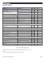
1
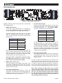
NMEA 2000 PC Interface (using the Actisense Comms API) NGT-1-ISO (All hardware revisions) Installation Manual Issue 1.01 Gateway to connect between a PC’s serial (RS232) port and the NMEA 2000 network Uses the Actisense Comms API for bi-directional PC communications Complete electrical isolation (of 1500 volts) between serial port and the NMEA 2000 connections Fully configurable via serial port or through the NMEA 2000 network NMEA 2000 PC Interface - NGT-1-ISO Contents Important notices Notices Foreword Introduction Technical features Software updates Connecting devices together 4 4 4 4 5 5 5 Connections Connecting to the NMEA 2000 network 6 7 Connecting to an RS232 (PC) port 7 Specifications Troubleshooting guide 8 9 Product order codes Company Information 10 10 The NMEA 2000 standard NMEA 2000 connections RS232 Connections Status LEDs © 2013 Active Research Limited 5 7 7 9 Page 3 Important notices Foreword Actisense and the Actisense logo are registered trademarks of Active Research Limited. All rights are reserved. The contents of this manual may not be transferred or copied without the expressed written permission of Active Research Limited. All other trademarks are the property of their respective owners. At Active Research Limited, we recognise that instructions are often skipped, so we have aimed to write this document in an informative and direct manner that will aid the user. We have covered all the points a typical user needs to know. The Actisense NMEA 2000 PC Interface (NGT-1-ISO) is intended for use in a marine environment, primarily for below deck use. If the NGT-1-ISO is to be used in a more severe environment, such use may be considered misuse under the seller’s guarantee. The NGT-1-ISO has been certified to comply with the European directive for Electro-Magnetic Compatibility (EN60945), and is appropriately CE marked. Operation of the unit should be in conjunction with appropriate CE approved shielded connectors and cabling used in accordance with the CE directive EN60945. Any EMC related issues should be reported to Active Research immediately to allow the company to rectify or resolve EMC related problems in accordance with its obligations under EN60945. If the unit is misconnected so that compliance failure occurs, the company shall not be held responsible for compliance failure until suitable EMC guidelines for connection are seen to have been taken. Notices When using this document, please note the following: The products described in this manual and the specifications thereof may be changed without prior notice. To obtain up-to-date information and/or specifications, contact Active Research Limited or visit the Actisense website (www.actisense.com). Active Research Limited will not be liable for infringement of copyright, industrial property right, or other rights of a third party caused by the use of information or drawings described in this manual. Active Research Limited will not be held responsible for any damage to the user that may result from an accident during operation of this unit when used in accordance with this document. © 2013 Active Research Limited Please read all sections before installing and using the NGT-1-ISO, and any related software programs. Introduction The NGT-1-ISO allows installers of equipment to adopt the NMEA 2000 network early, and enjoy the advantages of a single bus connection to all marine electronic devices around the entire boat. The NMEA 2000 network reduces installation costs of marine equipment and greatly reduce a boat’s wiring harness complexity, leading to improved reliability and reduction in unnecessary weight. Now only a single cable is required from the bridge to the engines, sensors and all other NMEA 2000 instruments on the boat NMEA 2000 uses the “CAN Bus” system (prevalent in most modern cars), to provide the quality and security of data transmissions that the NMEA 0183 bus can never hope to provide. This enables NMEA 2000 products to achieve better data transmission reliability in the passage of data through the vessel. The Actisense ‘Certified Software’ programme offers PC software manufacturers a quick method of adding an NGT-1 interface to their products - allowing them to share and interact safely on the NMEA 2000 network via the PC’s serial port. The NGT-1 interface acts much like a firewall - preventing illegal operations and maintaining the integrity of the NMEA 2000 network. As more PC software manufacturers use the NGT-1 interface to offer NMEA 2000 support to their customers, more users will experience the benefits of NMEA 2000. Full information on the complete Actisense product range and a list of all Actisense ‘NGT Certified Software’ products can be found on the Actisense website (www. actisense.com). Page 4 NMEA 2000 PC Interface - NGT-1-ISO Technical features High-speed 32-bit ARM processor capable of up to 40 million instructions per second. Flash ROM technology that supports automatic programming for quick and easy updates, 10,000+ erase cycles and a 10-year Data Retention provides carefree user configuration. On-chip memory store allows buffering of short term NMEA data, allowing the unit to smooth short-term peaks in the NMEA data flow. Fully configurable via the serial or over the NMEA 2000 network allowing optimization of the PC interface to better suit the system it is a part of. NMEA 2000 interface, opto-isolated to 2500 volts, protecting the system even during the most extreme fault conditions and fully compliant with the NMEA 2000 standard for interfacing with the NMEA 2000 network. Connecting devices together The NMEA 2000 standard The NMEA 2000 system is a low-cost data network operating at 250 kbits/sec utilizing the Controller Area Network (CAN). Multiple devices can be connected together on a single trunk cable to simply and easily share information between themselves. NMEA 2000 uses a shielded cable and a ”differential” signalling scheme, whereby two wires are used to transmit the NMEA data named CAN High and CAN Low. These connections will be labelled as “NET HI” and “NET LO” respectively. Power is also supplied through the NMEA 2000 cable named NET Supply and NET Common. These connections will be labelled “NET SUP” and “NET COM” respectively on the PCB. Please refer to the Connecting to the NMEA 2000 Network section for an example of these connection methods. NMEA 2000 network powered to offer easy installation with no need for a direct connection to the vessels main battery supply. The NGT-1-ISO takes all its power from the NMEA 2000 network connection and contain a clever built-in power isolator to supply its serial port circuitry without the need of an extra battery source. This creates total isolation between the serial and NMEA 2000 circuitry to completely eliminate the risk of ground loop faults occurring and the resulting damage. Software updates The NGT-1-ISO’s built-in firmware is held in “flash” memory, allowing quick and easy upgrades using either the latest NGT-1-ISO ActiPatch, or alternatively the NMEA 2000 Gateway Configuration Tool running on a PC connected to the NGT-1-ISO. It is our policy to provide these updates free on the Actisense website (www.actisense.com), so that the NMEA 2000 PC Interface (NGT-1-ISO) can become more sophisticated with time, and should there be any bugs reported in the firmware, they can be promptly fixed without the unit requiring to come out of commission. © 2013 Active Research Limited Page 5 Connections 3 1 4 2 5 Figure 1 – All external connections Figure 1 shows an internal view of the NGT-1-ISO Printed Circuit Board (PCB). 1. NMEA 2000 Interface A five way screw terminal block is supplied for connecting the NMEA 2000 cable. The CAN interface is fully compatible with the NMEA 2000 standard. Actisense supplies a pre-fitted four-core screened cable for the NMEA 2000 connection, fitted with a male micro-fit connector. The colour codes used for this cable are: Wire colour NMEA 2000 Shield / Screen SHIELD Blue NET LO White NET HI Black NET COM Red NET SUP If you need to use your own NMEA 2000 cable, the five way screw terminal block is provided within the NGT-1 to allow easy connection, along with a spare cable gland that should be fitted on to the new cable to help maintain the water protection level. Any such cable is required to conform in full to the NMEA 2000 specification and be no longer than 6 metres (maximum drop length). 2. NMEA 2000 indicator LED This LED flashes when NMEA 2000 data to be transferred is received by the NGT-1-ISO. It can be clearly seen through the NGT-1-ISO’s translucent lid when the case is closed. 3. Serial opto-isolated input. Two screw terminals are provided to connect the serial input. The serial input is of the differential optoisolated type and uses the unique Actisense low current drain circuitry (2 mA @ 2.0 v). © 2013 Active Research Limited 4. Serial ISO-Drive output. Three screw terminals are provided to connect to the serial ISO-Drive output. The serial output comprises of three connections: ‘+’, ‘-‘ and ‘Ground (GND)’. The colour codes used for this cable are: Wire colour Serial Shield / Screen ISO Ground Blue ISO Out B / - White ISO Out A / + Black Opto In B / - Red Opto In A / + In most installations, this ground (GND) can be left disconnected. It is useful where an “RS485” or “IEC61162-2” 3 terminal type connection is required, or where ground continuity is needed between source and target connections. No damage will be caused by connecting to this GND in error. Always follow the connection diagrams shown in this manual to ensure correct operation. 5. Serial data indicator LED This LED flashes when serial data to be transferred is received by the NGT-1-ISO. It can be clearly seen through the NGT-1-ISO’s translucent lid when the case is closed. To open the NGT-1-ISO, remove the two screws in the base of the unit, then slide off the top of the case. The cable glands need to be slid out from the top of the case in order to access the internal connections. The NGT-1ISO circuitry will be left attached to the base of the unit and the two supplied cables attached to their connectors. Note: When opening the NGT-1-ISO case, be aware that the circuitry inside is not 100% protected against static electricity. Please ensure that, when opening the case, you use precautions against static damage by only touching the connector block and by holding the unit by its plastic base. In this way, the risks of static damage will be minimised. Page 6 NMEA 2000 PC Interface - NGT-1-ISO CAN Network Connecting to the NMEA 2000 network CAN Lo CAN Hi Shield NET COM NET SUP Figure 2 – NMEA 2000 connections NMEA 2000 connections The Actisense NGT-1-ISO is designed to be connected to the vessel’s NMEA 2000 network using the supplied, pre-fitted Actisense cable. If a different length cable is required, an NMEA 2000 certified cable of the required length (maximum 6 metres) should be connected to the vessel’s NMEA 2000 network using a standard NMEA 2000 connector. The standard wiring connection can be seen in Figure 2. Note: 1. Wire colours are for guidance only. The colours given relate to the supplied Actisense cable and the NMEA 2000 standard cable definition. Connecting to an RS232 (PC) port TX Pin 3 RX Pin 2 Do not connect GND Personal Computer ( 9 PIN 'D' RS232 Port) Pin 5 Figure 3 – RS232 port connections RS232 Connections The NGT-1-ISO can be connected to a PC communications (RS232) port using the supplied Actisense cable and a connector with the following specification: 1. A minimum of 3-cores are required in a shielded cable. Higher quality cable will naturally yield higher performance / higher Signal-to-Noise Ratio (SNR). Most typical cables have two twisted pairs inside. In this case, use one pair for the TX line and one for the RX line. Use the spare wire in each pair as ground, and connect the cable shield to ground only at the computer end. © 2013 Active Research Limited 2. A D-type female (socket) connector for the PC end of the cable. 3. The OUT +/A of the NGT-1-ISO should be connected to the RX of the computer (standard D-type, pin 2) and the NGT-1-ISO IN +/A should be connected to the TX of the computer (pin 3). 4. Connect the IN -/B and OUT -/B together and connect to the PC’s serial port ground (pin 5). Page 7 Specifications Parameter Conditions Min. Max. Unit 8 35 V Supply voltage = 12v 26 30 mA Supply voltage = 24v 16 18 mA Supply Supply voltage Supply current (see note 1) NMEA 2000 CAN Bus line (CAN-H; CAN-L) Transmitter Recessive bus voltage VTXD = VDD; no load. 2.0 3.0 V Dominant bus voltage CAN-H VTXD = 0.8V 2.75 4.5 V Dominant bus voltage CAN-L VTXD = 0.8V 0.5 2.25 V Recessive differential output voltage VTXD = 2V; no load -500 50 mV Dominant differential output voltage 40Ω < RL < 60Ω 1.5 3.0 V Short circuit output current CAN-H VCAN-H = -5V - -200 mA Short circuit output current CAN-L VCAN-H = -40V, +40V. (see note 2) - 200 mA CAN-H, CAN-L common-mode input resistance 5 50 KΩ Differential input resistance 20 100 KΩ Continuous operation -15 +15 V Short term operation (< 1 sec) -35 +35 V Required level for data to be detected 1.8 - V - 2 mA 4800 230400 bps - 20 mA 2.1 - V - 1500 V 4800 230400 bps -20 +70 °C NMEA 2000 CAN Bus line (CAN-H; CAN-L) Receiver Opto-isolated Input Input voltage tolerance Differential input voltage Input current Input to Ground Baud rate Configurable Baud rate ISO-Drive Output Output current RS485 / RS422 / RS232 compatible Differential output voltage 100 ohm load Output to Ground Full Galvanic isolation protection Baud rate Configurable Baud rate General Ambient operating temperature Table 2 – NGT-1-ISO specifications All specifications are taken with reference to an ambient temperature (TA) of +25°C. Note: 1. Current consumption measured under no-load conditions © 2013 Active Research Limited Page 8 NMEA 2000 PC Interface - NGT-1-ISO Troubleshooting guide This guide will concentrate on all relevant troubleshooting issues above simple cable connection faults. Therefore, the cables between the NGT-1-ISO hardware and any other devices should be checked as a matter of course, before continuing with this guide. Status LEDs The NGT-1-ISO hardware has two bright LEDs that can be seen through the case to indicate when data is received from either the serial device or NMEA 2000 network connection. It is an important point to note that these two LEDs can only show when their respective data is RECEIVED; it is not possible to show both transmit and receive simultaneously on a single colour LED. These LEDs can be used to debug potential problems. If both an NMEA 2000 ‘talker’ and a ‘listener’ are connected, it is possible to analyse which is working by disconnecting one of them or by stopping the PC software from sending data. Sequence Description NMEA 2000 LED does not Check that the NGT-1-ISO is connected to the NMEA 2000 network, that the NMEA flash when the data is received 2000 network is operational, and that the required PGN messages are selected for from the NMEA 2000 network transfer by using the NGT Configuration Tool. Serial LED does not flash when Serial data is being received Check that the NGT-1-ISO is connected correctly to a PC serial port, that COM port is working in the Windows Device Manager, is selected by the software program and that the required messages are selected to be transferred by using the NGT Configuration Tool. Both LEDs flash together, once every 10 seconds Indicates that the NGT-1-ISO is powered but no data is received from either connection. If data should be being transferred through then check that the required PGN messages are selected by using the NGT Configuration Tool. If the error persists, please contact Actisense support to help trace the issue before considering the return of the product. If Actisense support concludes that the NGT-1-ISO unit should be returned to Actisense (refer to the Company Information section), a Returns Number will be issued by the support engineer. The Returns Number must be clearly visible on both the external packaging and any documentation returned with the product. Any returns sent without a Returns Number will incur a delay in being processed. Table 3 – Diagnostic LED © 2013 Active Research Limited Page 9 Product order codes NGT-1-ISO NGT-1-USB NMEA 2000 ↔ Serial Interface with ISO-Drive Special version required to connect the NMEA 2000 network to a serial port (on a computer running Actisense certified software) NMEA 2000 ↔ USB Interface Standard version required to connect the NMEA 2000 network to a USB port (on a computer running Actisense certified software) Company Information Active Research Limited Unit 5 Wessex Trade Centre Ringwood Road Poole Dorset. UK BH12 3PF Telephone: Fax: 01202 746682 (International : +44 1202 746682) 01202 746683 (International : +44 1202 746683) Actisense on the Web: For advice, support and product details E-mail: Website: [email protected] www.actisense.com “Actisense” is a registered trademark of Active Research Limited. © 2013 Active Research Limited Page 10 The NGT-1-ISO enables software certified to work with the Actisense interface standard to talk to devices on an NMEA 2000 network. NMEA 2000 network data is freely available to any Actisense certified PC software to display. As an NMEA certified firewall, the NGT-1 allows NMEA 2000 data to be sent from the PC to control any NMEA 2000 devices on the network. Benefits •All NMEA 2000 instruments on the network can receive data sent from compatible PC software •Compatible PC software can receive data from any NMEA 2000 instrument •Electrical isolation separates the two networks, protecting against ground loop faults. This creates a protected computer and a safe installation •Free Actisense diagnostic software shows what data and devices are on the NMEA 2000 network The isolating ISO-Drive connection of the NGW-1-ISO makes it one of the safest ways to connect your computer to an NMEA 2000 network. Just connect and relax, knowing that Actisense has it secured. Specifications NMEA 2000 Connection •NMEA 2000 network is opto-isolated from the serial connection to offer 1500 volts of protection •NMEA 2000 current draw 30 mA typical •Terminal block available for user cable connection •Cable length 1.5 metres Opto & ISO-Drive Connection • Exceeds all IEC 61162-2 electrical in/out specifications •Compatible with RS422 (NMEA), RS232 & RS485 •Baud rates 4800 to 230400 •Cable length 1.5 metres System Requirements • Supported OS’s: Windows (2000, XP and Vista). Check website for other versions • No drivers required Certifications •CE (EN60945) •Tested and certified NMEA 2000 compliant Environmental •Recommended operating temperature: -20°C to +70°C •Splash proof plastic casing provided with sealing cable glands certified to IP54 •Stainless steel case screws •Humidity: 0-80% RH ® Guarantee •3 years return to base Active Research Limited, Unit 5 Wessex Trade Centre, Ringwood Road, Poole, Dorset, UK, BH12 3PF Telephone: +44 (0)1202 746682 Fax: +44 (0)1202 746683 Actisense on the Web: For advice, support and product details E-mail: [email protected] Website: www.actisense.com “Actisense” is a registered trademark of Active Research Limited.