1
User Manual
Product Model : DWS-3000 Series
DWL-3500AP/8500AP
Unified Access System
Release 1
©Copyright 2006. All rights reserved.
Information in this document is subject to change without notice.
© 2005 D-Link Computer Corporation. All rights reserved.
Reproduction in any manner whatsoever without the written permission of D-Link Computer Corporation is strictly forbidden.
Trademarks used in this text: D-Link and the D-Link logo are trademarks of D-Link Computer Corporation; Microsoft and Windows
are registered trademarks of Microsoft Corporation.
Other trademarks and trade names may be used in this document to refer to either the entities claiming the marks and names or their
products. D-Link Computer Corporation disclaims any proprietary interest in trademarks and trade names other than its own.
FCC Warning
This equipment has been tested and found to comply with the limits for a Class A digital device, pursuant to Part 15 of the FCC Rules.
These limits are designed to provide reasonable protection against harmful interference when the equipment is operated in a
commercial environment. This equipment generates, uses, and can radiate radio frequency energy and, if not installed and used in
accordance with this user’s guide, may cause harmful interference to radio communications. Operation of this equipment in a
residential area is likely to cause harmful interference in which case the user will be required to correct the interference at his own
expense.
CE Mark Warning
This is a Class A product. In a domestic environment, this product may cause radio interference in which case the user may be required
to take adequate measures.
Warnung!
Dies ist ein Produkt der Klasse A. Im Wohnbereich kann dieses Produkt Funkstoerungen verursachen. In diesem Fall kann vom
Benutzer verlangt werden, angemessene Massnahmen zu ergreifen.
Precaución!
Este es un producto de Clase A. En un entorno doméstico, puede causar interferencias de radio, en cuyo case, puede requerirse al
usuario para que adopte las medidas adecuadas.
Attention!
Ceci est un produit de classe A. Dans un environnement domestique, ce produit pourrait causer des interférences radio, auquel cas
l`utilisateur devrait prendre les mesures adéquates.
Attenzione!
Il presente prodotto appartiene alla classe A. Se utilizzato in ambiente domestico il prodotto può causare interferenze radio, nel cui caso
è possibile che l`utente debba assumere provvedimenti adeguati.
VCCI Warning
2
Table of Contents
List of Tables . . . . . . . . . . . . . . . . . . . . . . . . . . . . . . . . . . . . . . . . . . . 9
List of Figures . . . . . . . . . . . . . . . . . . . . . . . . . . . . . . . . . . . . . . . . . 11
About This Document . . . . . . . . . . . . . . . . . . . . . . . . . . . . . . . . . . . 13
Audience . . . . . . . . . . . . . . . . . . . . . . . . . . . . . . . . . . . . . . . . . . . . . . . . . . .
Organization . . . . . . . . . . . . . . . . . . . . . . . . . . . . . . . . . . . . . . . . . . . . . . . .
Document Conventions . . . . . . . . . . . . . . . . . . . . . . . . . . . . . . . . . . . . . . . .
Safety Instructions. . . . . . . . . . . . . . . . . . . . . . . . . . . . . . . . . . . . . . . . . . . .
13
13
13
14
Safety Cautions . . . . . . . . . . . . . . . . . . . . . . . . . . . . . . . . . . . . . . . . . . . . . . . .
General Precautions for Rack-Mountable Products. . . . . . . . . . . . . . . . . . . .
Protecting Against Electrostatic Discharge . . . . . . . . . . . . . . . . . . . . . . . . . .
Battery Handling Reminder. . . . . . . . . . . . . . . . . . . . . . . . . . . . . . . . . . . . . . .
14
16
17
17
1 Overview of the D-Link Unified Access System . . . . . . . . . . . 19
D-Link Unified Access System Components . . . . . . . . . . . . . . . . . . . . . . . .
19
D-Link WLAN Controller Switch . . . . . . . . . . . . . . . . . . . . . . . . . . . . . . . . . .
D-Link Access Point . . . . . . . . . . . . . . . . . . . . . . . . . . . . . . . . . . . . . . . . . . . .
WLAN Visualization . . . . . . . . . . . . . . . . . . . . . . . . . . . . . . . . . . . . . . . . . . . .
19
20
20
D-Link Unified Access System Topology . . . . . . . . . . . . . . . . . . . . . . . . . .
21
Single WCS Deployment . . . . . . . . . . . . . . . . . . . . . . . . . . . . . . . . . . . . . . . . .
Peer Switch WCS Deployment . . . . . . . . . . . . . . . . . . . . . . . . . . . . . . . . . . . .
21
22
Understanding the User Interfaces. . . . . . . . . . . . . . . . . . . . . . . . . . . . . . .
23
Using the Web Interface . . . . . . . . . . . . . . . . . . . . . . . . . . . . . . . . . . . . . . . . .
Using the Command-Line Interface . . . . . . . . . . . . . . . . . . . . . . . . . . . . . . . .
Using SNMP . . . . . . . . . . . . . . . . . . . . . . . . . . . . . . . . . . . . . . . . . . . . . . . . . .
24
26
27
Wireless System Features and Standards Support . . . . . . . . . . . . . . . . . . .
28
2 Planning the D-Link Unified Access System Network . . . . . . 31
System Requirements . . . . . . . . . . . . . . . . . . . . . . . . . . . . . . . . . . . . . . . . .
WLAN Topology Considerations . . . . . . . . . . . . . . . . . . . . . . . . . . . . . . . .
31
32
Access Point-to-Switch Discovery. . . . . . . . . . . . . . . . . . . . . . . . . . . . . . . . . .
Access Point Placement. . . . . . . . . . . . . . . . . . . . . . . . . . . . . . . . . . . . . . . . . .
34
34
Network Planning to Support Layer 3 Roaming. . . . . . . . . . . . . . . . . . . . .
35
3 Installing the Hardware . . . . . . . . . . . . . . . . . . . . . . . . . . . . . . . 37
Hardware Overview . . . . . . . . . . . . . . . . . . . . . . . . . . . . . . . . . . . . . . . . . .
37
Front Panel Components. . . . . . . . . . . . . . . . . . . . . . . . . . . . . . . . . . . . . . . . .
LED Indicators . . . . . . . . . . . . . . . . . . . . . . . . . . . . . . . . . . . . . . . . . . . . . . . .
Rear Panel Description . . . . . . . . . . . . . . . . . . . . . . . . . . . . . . . . . . . . . . . . . .
Side Panels . . . . . . . . . . . . . . . . . . . . . . . . . . . . . . . . . . . . . . . . . . . . . . . . . . .
38
38
40
40
Installation . . . . . . . . . . . . . . . . . . . . . . . . . . . . . . . . . . . . . . . . . . . . . . . . .
41
Package Contents . . . . . . . . . . . . . . . . . . . . . . . . . . . . . . . . . . . . . . . . . . . . . .
Installation Guidelines . . . . . . . . . . . . . . . . . . . . . . . . . . . . . . . . . . . . . . . . . .
Installing the Switch without the Rack . . . . . . . . . . . . . . . . . . . . . . . . . . . . . .
41
41
42
3
D-Link Unified Access System User Manual
Installing the Switch in a Rack. . . . . . . . . . . . . . . . . . . . . . . . . . . . . . . . . . . . .
Powering On the Switch. . . . . . . . . . . . . . . . . . . . . . . . . . . . . . . . . . . . . . . . . .
Installing the SFP ports . . . . . . . . . . . . . . . . . . . . . . . . . . . . . . . . . . . . . . . . . .
Installing the Optional Module . . . . . . . . . . . . . . . . . . . . . . . . . . . . . . . . . . . .
Connecting to the External Redundant Power System . . . . . . . . . . . . . . . . . .
42
43
43
44
46
Connecting the Switch . . . . . . . . . . . . . . . . . . . . . . . . . . . . . . . . . . . . . . . .
46
Connecting the Switch to the Network . . . . . . . . . . . . . . . . . . . . . . . . . . . . . . .
Connecting the Switch and AP Directly. . . . . . . . . . . . . . . . . . . . . . . . . . . . . .
Connecting the Switch and AP through the L2/L3 Network . . . . . . . . . . . . . .
Connecting to the Core Network . . . . . . . . . . . . . . . . . . . . . . . . . . . . . . . . . . .
47
47
48
48
4 Installing the D-Link Unified Access System . . . . . . . . . . . . . .49
System Deployment Overview. . . . . . . . . . . . . . . . . . . . . . . . . . . . . . . . . . .
Connecting the Switch to the Network . . . . . . . . . . . . . . . . . . . . . . . . . . . .
Enabling the WLAN Features on the Switch . . . . . . . . . . . . . . . . . . . . . . .
Preparing the Access Points . . . . . . . . . . . . . . . . . . . . . . . . . . . . . . . . . . . .
49
51
52
54
Logging on to the AP . . . . . . . . . . . . . . . . . . . . . . . . . . . . . . . . . . . . . . . . . . . .
Changing the AP Password . . . . . . . . . . . . . . . . . . . . . . . . . . . . . . . . . . . . . . .
Configuring 802.1x Authentication Information on the AP. . . . . . . . . . . . . . .
Configuring AP-to-Switch Authentication Information . . . . . . . . . . . . . . . . . .
Configuring VLAN Information on the Access Point. . . . . . . . . . . . . . . . . . . .
54
55
55
56
56
Discovering Access Points and Peer Switches . . . . . . . . . . . . . . . . . . . . . .
57
Understanding the Discovery Methods . . . . . . . . . . . . . . . . . . . . . . . . . . . . . .
Discovery and Peer Switches. . . . . . . . . . . . . . . . . . . . . . . . . . . . . . . . . . . . . .
Assigning the IP Address to Switches and Managed APs . . . . . . . . . . . . . . . .
Enabling the AP and Peer Switch Discovery. . . . . . . . . . . . . . . . . . . . . . . . . .
57
60
60
63
Authenticating and Validating Access Points . . . . . . . . . . . . . . . . . . . . . . .
70
Configuring AP Authentication . . . . . . . . . . . . . . . . . . . . . . . . . . . . . . . . . . . .
Using the Local Database for AP Validation . . . . . . . . . . . . . . . . . . . . . . . . .
Using the RADIUS Database for AP Validation . . . . . . . . . . . . . . . . . . . . . . .
Managing Failed or Rogue APs . . . . . . . . . . . . . . . . . . . . . . . . . . . . . . . . . . .
71
72
74
76
5 Configuring Access Point Settings . . . . . . . . . . . . . . . . . . . . . . .77
4
AP Profiles, Networks, and the Local Database . . . . . . . . . . . . . . . . . . . .
77
Access Point Profiles . . . . . . . . . . . . . . . . . . . . . . . . . . . . . . . . . . . . . . . . . . . .
Networks . . . . . . . . . . . . . . . . . . . . . . . . . . . . . . . . . . . . . . . . . . . . . . . . . . . . .
Local Access Point Database. . . . . . . . . . . . . . . . . . . . . . . . . . . . . . . . . . . . . .
77
78
78
Configuring AAA and RADIUS Settings . . . . . . . . . . . . . . . . . . . . . . . . .
Configuring Wireless Radio Settings . . . . . . . . . . . . . . . . . . . . . . . . . . . .
Configuring SSID Settings . . . . . . . . . . . . . . . . . . . . . . . . . . . . . . . . . . . .
79
80
86
Managing Virtual Access Point Configuration . . . . . . . . . . . . . . . . . . . . . . . .
Configuring the Default Network. . . . . . . . . . . . . . . . . . . . . . . . . . . . . . . . . . .
Enabling and Configuring Additional VAPs . . . . . . . . . . . . . . . . . . . . . . . . . .
Configuring a VAP for L3 Tunnels . . . . . . . . . . . . . . . . . . . . . . . . . . . . . . . . .
Configuring AP Security . . . . . . . . . . . . . . . . . . . . . . . . . . . . . . . . . . . . . . . . .
86
87
90
91
93
Configuring Valid Access Point Settings . . . . . . . . . . . . . . . . . . . . . . . . .
98
© 2001- 2006 D-Link Corporation/D-Link Systems, Inc. All Rights Reserved.
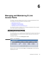
6 Managing and Maintaining D-Link Access Points . . . . . . . . 103
Resetting the Access Points . . . . . . . . . . . . . . . . . . . . . . . . . . . . . . . . . . .
Managing Radio Frequency Settings . . . . . . . . . . . . . . . . . . . . . . . . . . .
103
104
Configuring Channel Plan and Power Settings . . . . . . . . . . . . . . . . . . . . . .
Viewing the Channel Plan History . . . . . . . . . . . . . . . . . . . . . . . . . . . . . . . .
Initiating Manual Channel Plan Assignments. . . . . . . . . . . . . . . . . . . . . . . .
Initiating Manual Power Adjustments. . . . . . . . . . . . . . . . . . . . . . . . . . . . . .
104
107
108
109
Upgrading the Access Point Software . . . . . . . . . . . . . . . . . . . . . . . . . . .
Performing Advanced Access Point Management . . . . . . . . . . . . . . . . .
110
112
Enabling AP Debugging . . . . . . . . . . . . . . . . . . . . . . . . . . . . . . . . . . . . . . . .
Adjusting the Channel and Power. . . . . . . . . . . . . . . . . . . . . . . . . . . . . . . . .
113
114
7 Monitoring Status and Statistics . . . . . . . . . . . . . . . . . . . . . . . 117
Monitoring Wireless Global Information . . . . . . . . . . . . . . . . . . . . . . . .
117
Viewing IP Discovery Status . . . . . . . . . . . . . . . . . . . . . . . . . . . . . . . . . . . . .
120
Monitoring Peer Switch Status . . . . . . . . . . . . . . . . . . . . . . . . . . . . . . . .
Monitoring All Access Points . . . . . . . . . . . . . . . . . . . . . . . . . . . . . . . . .
Monitoring Managed Access Point Status . . . . . . . . . . . . . . . . . . . . . . . .
120
121
123
Monitoring Managed AP Statistics . . . . . . . . . . . . . . . . . . . . . . . . . . . . . . . .
131
Viewing Access Point Authentication Failure Status . . . . . . . . . . . . . . . .
Monitoring Rogue and RF Scan Access Points . . . . . . . . . . . . . . . . . . .
Monitoring Associated Client Information. . . . . . . . . . . . . . . . . . . . . . .
135
136
138
Viewing Associated Client Status . . . . . . . . . . . . . . . . . . . . . . . . . . . . . . . . .
Viewing Associated Client SSID Status. . . . . . . . . . . . . . . . . . . . . . . . . . . . .
Viewing Associated Client VAP Status . . . . . . . . . . . . . . . . . . . . . . . . . . . . .
Viewing Associated Client Statistics . . . . . . . . . . . . . . . . . . . . . . . . . . . . . . .
139
141
142
142
Viewing Client Authentication Failure Status . . . . . . . . . . . . . . . . . . . . .
Monitoring and Managing Ad Hoc Clients . . . . . . . . . . . . . . . . . . . . . .
144
146
8 Configuring Advanced Settings. . . . . . . . . . . . . . . . . . . . . . . . 149
Creating, Configuring, and Managing AP Profiles . . . . . . . . . . . . . . . .
149
Creating, Copying, and Deleting AP Profiles. . . . . . . . . . . . . . . . . . . . . . . .
Applying an AP Profile . . . . . . . . . . . . . . . . . . . . . . . . . . . . . . . . . . . . . . . . .
151
152
Configuring Global Settings . . . . . . . . . . . . . . . . . . . . . . . . . . . . . . . . . .
Enabling SNMP Traps . . . . . . . . . . . . . . . . . . . . . . . . . . . . . . . . . . . . . .
Configuring QoS . . . . . . . . . . . . . . . . . . . . . . . . . . . . . . . . . . . . . . . . . . . .
153
154
156
9 Visualizing the Wireless Network . . . . . . . . . . . . . . . . . . . . . . 161
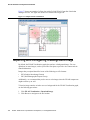
Importing and Configuring a Background Image . . . . . . . . . . . . . . . . .
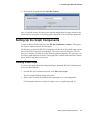
Setting Up the Graph Components . . . . . . . . . . . . . . . . . . . . . . . . . . . . . .
162
163
Creating a New Graph . . . . . . . . . . . . . . . . . . . . . . . . . . . . . . . . . . . . . . . . .
Graphing the WLAN Components. . . . . . . . . . . . . . . . . . . . . . . . . . . . . . . . .
163
166
Understanding the Menu Bar Options . . . . . . . . . . . . . . . . . . . . . . . . . . .
168
Legend Menu . . . . . . . . . . . . . . . . . . . . . . . . . . . . . . . . . . . . . . . . . . . . . . . . .
170
Managing the Graph. . . . . . . . . . . . . . . . . . . . . . . . . . . . . . . . . . . . . . . . .
173
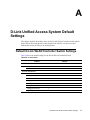
A D-Link Unified Access System Default Settings . . . . . . . . . . 175
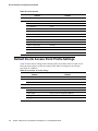
Default D-Link WLAN Controller Switch Settings . . . . . . . . . . . . . . . . . .
175
5
D-Link Unified Access System User Manual
Default D-Link Access Point Profile Settings. . . . . . . . . . . . . . . . . . . . . .
176
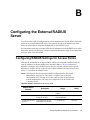
B Configuring the External RADIUS Server . . . . . . . . . . . . . . .179
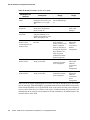
Configuring RADIUS Settings for Access Points . . . . . . . . . . . . . . . . . . .
FreeRADIUS Server Configuration Example. . . . . . . . . . . . . . . . . . . . . .
179
181
Configuring RADIUS Clients. . . . . . . . . . . . . . . . . . . . . . . . . . . . . . . . . . . . .
Creating and Including an Attribute Dictionary . . . . . . . . . . . . . . . . . . . . . .
Adding Access Points to the Valid AP Database . . . . . . . . . . . . . . . . . . . . . .
181
181
183
Configuring RADIUS Settings for Wireless Clients . . . . . . . . . . . . . . . . .
184
Configuring RADIUS for Client MAC Authentication. . . . . . . . . . . . . . . . . .
184
FreeRADIUS Example for Wireless Client Configuration . . . . . . . . . . . .
184
Configuring User-Based Authentication and Dynamic VLANs. . . . . . . . . . .
Configuring MAC Authentication . . . . . . . . . . . . . . . . . . . . . . . . . . . . . . . . .
185
186
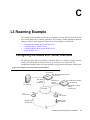
C L3 Roaming Example . . . . . . . . . . . . . . . . . . . . . . . . . . . . . . . .187
Configuring the WLAN and Tunnel Interfaces . . . . . . . . . . . . . . . . . . . . .
187
Using a Loopback Interface for the Wireless Functions . . . . . . . . . . . . . . . .
Creating the VLAN Routing Interface . . . . . . . . . . . . . . . . . . . . . . . . . . . . . .
188
189
Configuring the L3 Tunnel Network . . . . . . . . . . . . . . . . . . . . . . . . . . . . .
192
Example of Configuring L3 Roaming by Using the CLI . . . . . . . . . . . . . . . .
Example of Configuring L3 Roaming by Using the Web Interface . . . . . . . .
193
196
Configuring DHCP Relay and the DHCP Server. . . . . . . . . . . . . . . . . . .
197
Configuring the Relay Agent . . . . . . . . . . . . . . . . . . . . . . . . . . . . . . . . . . . . .
Configuring the DHCP Server. . . . . . . . . . . . . . . . . . . . . . . . . . . . . . . . . . . .
197
198
Setting the MTU Size. . . . . . . . . . . . . . . . . . . . . . . . . . . . . . . . . . . . . . . . .
200
D Understanding Quality of Service . . . . . . . . . . . . . . . . . . . . . .203
QoS and Load Balancing . . . . . . . . . . . . . . . . . . . . . . . . . . . . . . . . . . . . .
802.11e and WMM Standards Support. . . . . . . . . . . . . . . . . . . . . . . . . . .
Coordinating Traffic Flow . . . . . . . . . . . . . . . . . . . . . . . . . . . . . . . . . . . .
QoS Queues and DSCP on Packets . . . . . . . . . . . . . . . . . . . . . . . . . . . . .
EDCF Control of Data Frames and AIFS . . . . . . . . . . . . . . . . . . . . . . . .
Random Backoff and Contention Windows . . . . . . . . . . . . . . . . . . . . . . .
Packet Bursting for Better Performance . . . . . . . . . . . . . . . . . . . . . . . . .
TXOP Interval for Client Stations . . . . . . . . . . . . . . . . . . . . . . . . . . . . . .
802.1p and DSCP tags . . . . . . . . . . . . . . . . . . . . . . . . . . . . . . . . . . . . . . .
203
203
204
204
205
206
206
207
207
E Warranty and Registration Information. . . . . . . . . . . . . . . . .209
6
All countries and regions excluding USA . . . . . . . . . . . . . . . . . . . . . . . . .
209
WARRANTIES EXCLUSIVE . . . . . . . . . . . . . . . . . . . . . . . . . . . . . . . . . . . . .
LIMITATION OF LIABILITY . . . . . . . . . . . . . . . . . . . . . . . . . . . . . . . . . . . .
Limited Warranty . . . . . . . . . . . . . . . . . . . . . . . . . . . . . . . . . . . . . . . . . . . . . .
210
210
211
Limited Warranty (USA Only) . . . . . . . . . . . . . . . . . . . . . . . . . . . . . . . . .
Product Registration. . . . . . . . . . . . . . . . . . . . . . . . . . . . . . . . . . . . . . . . .
D-Link Europe Limited Product Warranty . . . . . . . . . . . . . . . . . . . . . . . .
212
216
216
Geographical Scope of the Limited Product Warranty . . . . . . . . . . . . . . . . .
Limitation of Product Warranty. . . . . . . . . . . . . . . . . . . . . . . . . . . . . . . . . . .
Limited Product Warranty Period . . . . . . . . . . . . . . . . . . . . . . . . . . . . . . . . .
217
217
218
© 2001- 2006 D-Link Corporation/D-Link Systems, Inc. All Rights Reserved.
Performance of the Limited Product Warranty. . . . . . . . . . . . . . . . . . . . . . .
Warrantor . . . . . . . . . . . . . . . . . . . . . . . . . . . . . . . . . . . . . . . . . . . . . . . . . . .
218
219
D-Link Europe Limited Produktgarantie . . . . . . . . . . . . . . . . . . . . . . . . .
219
Räumlicher Geltungsbereich der eingeschränkten Garantie . . . . . . . . . . . .
Einschränkung der Garantie . . . . . . . . . . . . . . . . . . . . . . . . . . . . . . . . . . . . .
Laufzeit der eingeschränkten Garantie . . . . . . . . . . . . . . . . . . . . . . . . . . . . .
Leistungsumfang der eingeschränkten Garantie. . . . . . . . . . . . . . . . . . . . . .
Garantiegeber . . . . . . . . . . . . . . . . . . . . . . . . . . . . . . . . . . . . . . . . . . . . . . . .
220
220
220
221
221
D-Link Europe a limité la garantie des produits . . . . . . . . . . . . . . . . . . .
222
Etendue géographique de la Garantie Produit Limitée . . . . . . . . . . . . . . . .
Limitation de la Garantie Produit. . . . . . . . . . . . . . . . . . . . . . . . . . . . . . . . .
Période de Garantie Produit Limitée . . . . . . . . . . . . . . . . . . . . . . . . . . . . . .
Exécution de la Garantie Produit Limitée . . . . . . . . . . . . . . . . . . . . . . . . . .
Garant . . . . . . . . . . . . . . . . . . . . . . . . . . . . . . . . . . . . . . . . . . . . . . . . . . . . . .
222
223
223
224
224
Garantía limitada del producto D-LINK Europa . . . . . . . . . . . . . . . . . . .
224
Cobertura geográfica de la garantía limitada del producto. . . . . . . . . . . . .
Limitación de la garantía del producto. . . . . . . . . . . . . . . . . . . . . . . . . . . . .
Período de la garantía limitada del producto. . . . . . . . . . . . . . . . . . . . . . . .
Uso de la garantía limitada del producto . . . . . . . . . . . . . . . . . . . . . . . . . . .
Garante . . . . . . . . . . . . . . . . . . . . . . . . . . . . . . . . . . . . . . . . . . . . . . . . . . . . .
225
225
226
226
227
D-Link Europe Termini di Garanzia dei Prodotti . . . . . . . . . . . . . . . . . .
227
Ambito geografico della Garanzia limitata. . . . . . . . . . . . . . . . . . . . . . . . . .
Limitazione della Garanzia . . . . . . . . . . . . . . . . . . . . . . . . . . . . . . . . . . . . . .
Periodo di garanzia. . . . . . . . . . . . . . . . . . . . . . . . . . . . . . . . . . . . . . . . . . . .
Prestazioni della Garanzia limitata . . . . . . . . . . . . . . . . . . . . . . . . . . . . . . .
Garante . . . . . . . . . . . . . . . . . . . . . . . . . . . . . . . . . . . . . . . . . . . . . . . . . . . . .
228
228
228
229
229
F Technical Support. . . . . . . . . . . . . . . . . . . . . . . . . . . . . . . . . . . 231
International Offices . . . . . . . . . . . . . . . . . . . . . . . . . . . . . . . . . . . . . . . . .
Registration Information. . . . . . . . . . . . . . . . . . . . . . . . . . . . . . . . . . . . . .
259
260
7
D-Link Unified Access System User Manual
8
© 2001- 2006 D-Link Corporation/D-Link Systems, Inc. All Rights Reserved.
List of Tables
List of Tables
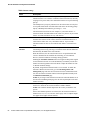
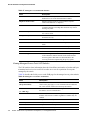
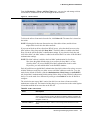
Table 1. Typographical Conventions . . . . . . . . . . . . . . . . . . . . . . . . . . . . . . . . . . 13
Table 2. LED Description . . . . . . . . . . . . . . . . . . . . . . . . . . . . . . . . . . . . . . . . . . 39
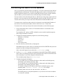
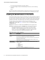
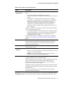
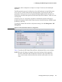
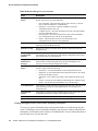
Table 3. Basic Wireless Global Configuration . . . . . . . . . . . . . . . . . . . . . . . . . . 52
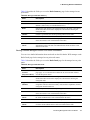
Table 4. IEEE 802.1x Supplicant Commands . . . . . . . . . . . . . . . . . . . . . . . . . . . 56
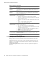
Table 5. AP VLAN Commands . . . . . . . . . . . . . . . . . . . . . . . . . . . . . . . . . . . . . . 57
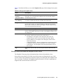
Table 6. L3/IP Discovery . . . . . . . . . . . . . . . . . . . . . . . . . . . . . . . . . . . . . . . . . . . 66
Table 7. Global RADIUS Server . . . . . . . . . . . . . . . . . . . . . . . . . . . . . . . . . . . . . 79
Table 8. MAC Authentication . . . . . . . . . . . . . . . . . . . . . . . . . . . . . . . . . . . . . . . 80
Table 9. Radio Settings . . . . . . . . . . . . . . . . . . . . . . . . . . . . . . . . . . . . . . . . . . . . 82
Table 10. Advanced Radio Configuration . . . . . . . . . . . . . . . . . . . . . . . . . . . . . . 85
Table 11. Default VAP Configuration . . . . . . . . . . . . . . . . . . . . . . . . . . . . . . . . . 87
Table 12. Wireless Network Configuration . . . . . . . . . . . . . . . . . . . . . . . . . . . . . 88
Table 13. Static WEP . . . . . . . . . . . . . . . . . . . . . . . . . . . . . . . . . . . . . . . . . . . . . . 95
Table 14. Static WPA . . . . . . . . . . . . . . . . . . . . . . . . . . . . . . . . . . . . . . . . . . . . . 97
Table 15. Valid Access Point Summary . . . . . . . . . . . . . . . . . . . . . . . . . . . . . . . 99
Table 16. Valid AP Configuration . . . . . . . . . . . . . . . . . . . . . . . . . . . . . . . . . . . 100
Table 17. RF Channel Plan and Power Adjustment . . . . . . . . . . . . . . . . . . . . . 106
Table 18. Channel Plan History . . . . . . . . . . . . . . . . . . . . . . . . . . . . . . . . . . . . . 108
Table 19. AP Upgrade . . . . . . . . . . . . . . . . . . . . . . . . . . . . . . . . . . . . . . . . . . . . 110
Table 20. AP Upgrade Status . . . . . . . . . . . . . . . . . . . . . . . . . . . . . . . . . . . . . . . 112
Table 21. Advanced AP Management . . . . . . . . . . . . . . . . . . . . . . . . . . . . . . . . 113
Table 22. AP Debug . . . . . . . . . . . . . . . . . . . . . . . . . . . . . . . . . . . . . . . . . . . . . . 114
Table 23. Managed AP Channel/Power Adjust . . . . . . . . . . . . . . . . . . . . . . . . . 114
Table 24. Global WLAN Statistics . . . . . . . . . . . . . . . . . . . . . . . . . . . . . . . . . . 118
Table 25. Peer Switch Status . . . . . . . . . . . . . . . . . . . . . . . . . . . . . . . . . . . . . . . 121
Table 26. Monitoring All Access Points . . . . . . . . . . . . . . . . . . . . . . . . . . . . . . 122
Table 27. Managed Access Point Status . . . . . . . . . . . . . . . . . . . . . . . . . . . . . . 123
Table 28. Detailed Managed Access Point Status . . . . . . . . . . . . . . . . . . . . . . . 125
Table 29. Managed AP Radio Summary . . . . . . . . . . . . . . . . . . . . . . . . . . . . . . 127
Table 30. Managed AP Radio Detail . . . . . . . . . . . . . . . . . . . . . . . . . . . . . . . . . 127
Table 31. Managed AP Neighbor Status . . . . . . . . . . . . . . . . . . . . . . . . . . . . . . 129
Table 32. Neighbor AP Clients . . . . . . . . . . . . . . . . . . . . . . . . . . . . . . . . . . . . . 130
Table 33. Managed Access Point VAP Status . . . . . . . . . . . . . . . . . . . . . . . . . . 131
Table 34. Managed Access Point WLAN Summary Statistics . . . . . . . . . . . . . 132
Table 35. Managed Access Point Ethernet Summary Statistics . . . . . . . . . . . . 132
Table 36. Detailed Managed Access Point Statistics . . . . . . . . . . . . . . . . . . . . . 133
Table 37. Managed Access Point Radio Statistics . . . . . . . . . . . . . . . . . . . . . . . 133
Table 38. Managed Access Point VAP Statistics . . . . . . . . . . . . . . . . . . . . . . . 134
Table 39. Access Point Authentication Failure Status . . . . . . . . . . . . . . . . . . . . 136
Table 40. Access Point RF Scan Status . . . . . . . . . . . . . . . . . . . . . . . . . . . . . . . 138
Table 41. Associated Client Status Summary . . . . . . . . . . . . . . . . . . . . . . . . . . 139
Table 42. Detailed Associated Client Status . . . . . . . . . . . . . . . . . . . . . . . . . . . 140
Table 43. Associated Client Neighbor AP Status . . . . . . . . . . . . . . . . . . . . . . . 141
9
D-Link Unified Access System User Manual
Table 44. Associated Client SSID Status . . . . . . . . . . . . . . . . . . . . . . . . . . . . . . 142
Table 45. Associated Client VAP Status . . . . . . . . . . . . . . . . . . . . . . . . . . . . . . 142
Table 46. Associated Client Association Summary Statistics . . . . . . . . . . . . . . 143
Table 47. Associated Client Summary Statistics . . . . . . . . . . . . . . . . . . . . . . . . 143
Table 48. Associated Client Association Detail Statistics . . . . . . . . . . . . . . . . . 143
Table 49. Associated Client Session Detail Statistics . . . . . . . . . . . . . . . . . . . . 144
Table 50. Failed Client Status . . . . . . . . . . . . . . . . . . . . . . . . . . . . . . . . . . . . . . 145
Table 51. Client Authentication Failure Status . . . . . . . . . . . . . . . . . . . . . . . . . 146
Table 52. Ad Hoc Client Status . . . . . . . . . . . . . . . . . . . . . . . . . . . . . . . . . . . . . 147
Table 53. General Global Configurations . . . . . . . . . . . . . . . . . . . . . . . . . . . . . 153
Table 54. SNMP Traps . . . . . . . . . . . . . . . . . . . . . . . . . . . . . . . . . . . . . . . . . . . 155
Table 55. QoS Settings . . . . . . . . . . . . . . . . . . . . . . . . . . . . . . . . . . . . . . . . . . . 157
Table 56. WLAN Visualization Menu Bar Options . . . . . . . . . . . . . . . . . . . . . 168
Table 57. Component Information . . . . . . . . . . . . . . . . . . . . . . . . . . . . . . . . . . . 173
Table 58. Switch Defaults . . . . . . . . . . . . . . . . . . . . . . . . . . . . . . . . . . . . . . . . . 175
Table 59. AP Default AP Profile Settings . . . . . . . . . . . . . . . . . . . . . . . . . . . . . 176
Table 60. RADIUS Attributes for the Access Point . . . . . . . . . . . . . . . . . . . . . 179
Table 61. RADIUS Attributes for Wireless Clients . . . . . . . . . . . . . . . . . . . . . 184
Table 62. RADIUS Attributes for Wireless Client MAC Authentication . . . . . 184
Table 63. L3 Tunnel Status Values . . . . . . . . . . . . . . . . . . . . . . . . . . . . . . . . . . 194
Table 64. VLAN Priority Tags . . . . . . . . . . . . . . . . . . . . . . . . . . . . . . . . . . . . . 208
10
© 2001- 2006 D-Link Corporation/D-Link Systems, Inc. All Rights Reserved.
List of Figures
List of Figures
Figure 1. Sample WLAN Visualization................................................................ 21
Figure 2. Single WCS with Layer 2 Roaming Support ........................................ 22
Figure 3. Peer WCS with Layer 3 Roaming Support ........................................... 23
Figure 4. Web Interface Layout ............................................................................ 24
Figure 5. Cascading Navigation Menu ................................................................. 25
Figure 6. Hierarchical Tree Navigation Menu...................................................... 25
Figure 7. D-Link Unified Access System Components........................................ 32
Figure 8. Wiring Closet Topology ........................................................................ 33
Figure 9. Data Center Topology ........................................................................... 34
Figure 10. Inter-Subnet Roaming ......................................................................... 36
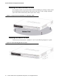
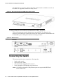
Figure 11. Front Panel View of the DWS-3024 as Shipped ................................. 38
Figure 12. Front Panel View of the DWS-3026 as Shipped ................................. 38
Figure 13. LED Indicators on DWS-3024 ............................................................ 38
Figure 14. LED Indicators on DWS-3026 ............................................................ 38
Figure 15. Rear panel view of DWS-3024 ........................................................... 40
Figure 16. Rear panel view of DWS-3026 ........................................................... 40
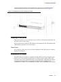
Figure 17. Prepare Switch for Installation on a Desktop or Shelf ........................ 42
Figure 18. Fasten Mounting Brackets to Switch................................................... 42
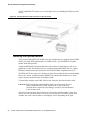
Figure 19. Mounting the Switch in a Standard 19" Rack ..................................... 43
Figure 20. Inserting the Fiber-Optic Transceivers into the Switch....................... 44
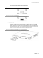
Figure 21. Front Panel of the DEM-410X ............................................................ 45
Figure 22. Front Panel of the DEM-410CX ......................................................... 45
Figure 23. Inserting the optional module into the Switch (DWS-3026)............... 45
Figure 24. DWS-3026 with optional DEM-410X module installed ..................... 46
Figure 25. RPS Connector .................................................................................... 46
Figure 26. Switch and AP Connected Directly..................................................... 47
Figure 27. Switch and APs Connected Through Network.................................... 48
Figure 28. Switch Connected to Network Core .................................................... 48
Figure 29. Ethernet Connection for Static IP Assignment.................................... 55
Figure 30. L2 Discovery Example ........................................................................ 58
Figure 31. L3 Discovery Example 1 ..................................................................... 58
Figure 32. L3 Discovery Example 2 ..................................................................... 59
Figure 33. DHCP Option Example ....................................................................... 59
Figure 34. Requiring AP Authentication .............................................................. 72
Figure 35. MAC Access Control .......................................................................... 80
Figure 36. Radio Settings...................................................................................... 81
Figure 37. VAP Settings ....................................................................................... 86
Figure 38. Configuring Network Settings............................................................. 88
Figure 39. AP Profile With Five VAPs Enabled .................................................. 90
Figure 40. Networks Available to the Wireless Client ......................................... 91
Figure 41. L3 Roaming Example.......................................................................... 92
Figure 42. AP Network Security Options ............................................................. 93
Figure 43. Static WEP Configuration ................................................................... 94
11
D-Link Unified Access System User Manual
Figure 44. WPA Personal Configuration .............................................................. 96
Figure 45. Adding a Valid AP .............................................................................. 99
Figure 46. Configuring a Valid AP..................................................................... 100
Figure 47. Access Point Reset ............................................................................ 103
Figure 48. RF Channel Plan and Power Configuration ...................................... 105
Figure 49. Channel Plan History......................................................................... 107
Figure 50. Manual Channel Plan ........................................................................ 108
Figure 51. Manual Power Adjustments .............................................................. 109
Figure 52. AP Upgrade ....................................................................................... 110
Figure 53. AP Upgrade Status. ........................................................................... 111
Figure 54. Advanced AP Management............................................................... 113
Figure 55. Global WLAN Status ........................................................................ 118
Figure 56. Wireless Discovery Status................................................................. 120
Figure 57. Peer Switch Status ............................................................................. 121
Figure 58. All Access Points............................................................................... 121
Figure 59. Managed AP Status ........................................................................... 123
Figure 60. Managed AP Statistics....................................................................... 131
Figure 61. Authentication Failed AP Status ....................................................... 135
Figure 62. RF Scan ............................................................................................. 137
Figure 63. Associated Client Status .................................................................... 138
Figure 64. Client Authentication Failure Status ................................................. 145
Figure 65. Ad Hoc Clients .................................................................................. 147
Figure 66. Multiple AP Profiles.......................................................................... 150
Figure 67. Adding a Profile ................................................................................ 151
Figure 68. Configuring an AP Profile................................................................. 151
Figure 69. Applying the AP Profile .................................................................... 152
Figure 70. Global Configuration......................................................................... 153
Figure 71. SNMP Trap Configuration ................................................................ 154
Figure 72. QoS Configuration ............................................................................ 156
Figure 73. Sample WLAN Visualization............................................................ 162
Figure 74. Multiple Graphs................................................................................. 166
Figure 75. List View and Tabbed View.............................................................. 166
Figure 76. Component Tool Tip ......................................................................... 167
Figure 77. Graphed Components ........................................................................ 168
Figure 78. Legend ............................................................................................... 170
Figure 79. Sentry Mode - Detailed View............................................................ 171
Figure 80. Channel Colors .................................................................................. 171
Figure 81. Tool Tip for Radio Managed AP Information................................... 172
Figure 82. Wireless Component Attributes ........................................................ 173
Figure 83. Example of a Network with L3 Tunnel Subnet................................. 187
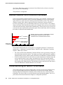
Figure 84. Traffic Prioritization.......................................................................... 208
12
© 2001- 2006 D-Link Corporation/D-Link Systems, Inc. All Rights Reserved.
About This Document
About This Document
This guide describes the planning, setup, configuration, administration, and maintenance for
the D-Link Unified Access System.
Audience
The information in this guide is intended for the person responsible for installing, configuring,
monitoring, and maintaining the D-Link Unified Access System as part of a network
infrastructure.
Organization
The D-Link Unified Access System User Manual contains the following chapters:
•
•
•
•
•
•
•
•
•
•
•
•
•
Chapter 1, “Overview of the D-Link Unified Access System” on page 19
Chapter 2, “Planning the D-Link Unified Access System Network” on page 31
Chapter 3, “Installing the Hardware” on page 37
Chapter 4, “Installing the D-Link Unified Access System” on page 49
Chapter 5, “Configuring Access Point Settings” on page 77
Chapter 6, “Managing and Maintaining D-Link Access Points” on page 103
Chapter 7, “Monitoring Status and Statistics” on page 117
Chapter 8, “Configuring Advanced Settings” on page 149
Chapter 9, “Visualizing the Wireless Network” on page 161
Appendix A, “D-Link Unified Access System Default Settings” on page 175
Appendix B, “Configuring the External RADIUS Server” on page 179
Appendix C, “L3 Roaming Example” on page 187
Appendix D, “Understanding Quality of Service” on page 203
Document Conventions
This section describes the conventions this document uses.
NOTE: A Note provides more information about a feature or technology.
CAUTION: A Caution provides information about critical aspects of the
configuration, combinations of settings, events, or procedures that can
adversely affect network connectivity, security, and so on.
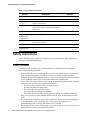
This guide uses the typographical conventions that Table 1 describes.
Table 1. Typographical Conventions
Symbol
Description
Example
Bold
Menu titles, page names, and button names
Click Submit to apply your
settings.
Blue Text
Hyperlinked text.
See “About This Document”
on page 13.
Audience
13
D-Link Unified Access System User Manual
Table 1. Typographical Conventions
Symbol
Description
Example
courier font
Screen text, file names.
(switch-prompt)#
courier bold
Commands, user-typed command-line entries
show network
courier font
italics
Command parameter, which might be a
variable or fixed value.
value
<> Angle brackets
Indicates a parameter is a variable. You must
enter a value in place of the brackets and text
inside them.
<value>
[ ] Square brackets
Indicates an optional fixed parameter.
[value]
[< >] Angle
brackets within
square brackets
Indicates an optional variable.
[<value>]
{} curly braces
Indicates that you must select a parameter
from the list of choices.
{choice1 | choice2}
| Vertical bars
Separates the mutually exclusive choices.
choice1 | choice2
[{}] Braces within
square brackets
Indicate a choice within an optional element.
[{choice1 | choice2}]
Safety Instructions
Use the following safety guidelines to ensure your own personal safety and to help protect
your system from potential damage.
Safety Cautions
To reduce the risk of bodily injury, electrical shock, fire, and damage to the equipment,
observe the following precautions.
•
•
•
•
•
14
Observe and follow service markings. Do not service any product except as explained in
your system documentation. Opening or removing covers that are marked with the
triangular symbol with a lightning bolt may expose you to electrical shock. Only a trained
service technician should service components inside these compartments.
If any of the following conditions occur, unplug the product from the electrical outlet and
replace the part or contact your trained service provider:
- The power cable, extension cable, or plug is damaged.
- An object has fallen into the product.
- The product has been exposed to water.
- The product has been dropped or damaged.
- The product does not operate correctly when you follow the operating instructions.
Keep your system away from radiators and heat sources. Also, do not block the cooling
vents.
Do not spill food or liquids on your system components, and never operate the product in
a wet environment. If the system gets wet, see the appropriate section in your
troubleshooting guide or contact your trained service provider.
Do not push any objects into the openings of your system. Doing so can cause a fire or an
electric shock by shorting out interior components.
© 2001- 2006 D-Link Corporation/D-Link Systems, Inc. All Rights Reserved.
About This Document
•
•
•
•
•
•
•
•
•
•
•
•
•
Use the product only with approved equipment.
Allow the product to cool before removing covers or touching internal components.
Operate the product only from the type of external power source indicated on the electrical
ratings label. If you are not sure of the type of power source required, consult your service
provider or local power company.
To help avoid damaging your system, be sure the voltage selection Switch (if provided) on
the power supply is set to match the power available at your location:
- 115 volts (V)/60 hertz (Hz) in most of North and South America and some Far Eastern
countries such as South Korea and Taiwan
- 100 V/50 Hz in eastern Japan and 100 V/60 Hz in western Japan
- 230 V/50 Hz in most of Europe, the Middle East, and the Far East
Also be sure that attached devices are electrically rated to operate with the power available
in your location.
Use only approved power cable(s). If you have not been provided with a power cable for
your system or for any AC-powered option intended for your system, purchase a power
cable that is approved for use in your country. The power cable must be rated for the
product and for the voltage and current marked on the product's electrical ratings label.
The voltage and current rating of the cable should be greater than the ratings marked on
the product.
To help prevent an electric shock, plug the system and peripheral power cables into
properly grounded electrical outlets. These cables are equipped with three-prong plugs to
help ensure proper grounding. Do not use adapter plugs or remove the grounding prong
from a cable. If you must use an extension cable, use a 3-wire cable with properly
grounded plugs.
Observe extension cable and power strip ratings. Make sure that the total ampere rating of
all products plugged into the extension cable or power strip does not exceed 80 percent of
the ampere ratings limit for the extension cable or power strip.
To help protect your system from sudden, transient increases and decreases in electrical
power, use a surge suppressor, line conditioner, or uninterruptible power supply (UPS).
Position system cables and power cables carefully; route cables so that they cannot be
stepped on or tripped over. Be sure that nothing rests on any cables.
Do not modify power cables or plugs. Consult a licensed electrician or your power
company for site modifications. Always follow your local/national wiring rules.
When connecting or disconnecting power to hot-pluggable power supplies, if offered with
your system, observe the following guidelines:
- Install the power supply before connecting the power cable to the power supply.
- Unplug the power cable before removing the power supply.
- If the system has multiple sources of power, disconnect power from the system by
unplugging all power cables from the power supplies.
Move products with care; ensure that all casters and/or stabilizers are firmly connected to
the system. Avoid sudden stops and uneven surfaces.
Safety Instructions
15
D-Link Unified Access System User Manual
General Precautions for Rack-Mountable Products
Observe the following precautions for rack stability and safety. Also refer to the rack
installation documentation accompanying the system and the rack for specific caution
statements and procedures.
•
Systems are considered to be components in a rack. Thus, “component” refers to any
system as well as to various peripherals or supporting hardware.
CAUTION: Installing systems in a rack without the front and side stabilizers installed
could cause the rack to tip over, potentially resulting in bodily injury
under certain circumstances. Therefore, always install the stabilizers
before installing components in the rack.
•
•
•
•
•
•
•
•
•
After installing system/components in a rack, never pull more than one component out of
the rack on its slide assemblies at one time. The weight of more than one extended
component could cause the rack to tip over and may result in serious injury.
Before working on the rack, make sure that the stabilizers are secured to the rack,
extended to the floor, and that the full weight of the rack rests on the floor. Install front and
side stabilizers on a single rack or front stabilizers for joined multiple racks before
working on the rack.
Always load the rack from the bottom up, and load the heaviest item in the rack first.
Make sure that the rack is level and stable before extending a component from the rack.
Use caution when pressing the component rail release latches and sliding a component
into or out of a rack; the slide rails can pinch your fingers.
After a component is inserted into the rack, carefully extend the rail into a locking
position, and then slide the component into the rack.
Do not overload the AC supply branch circuit that provides power to the rack. The total
rack load should not exceed 80 percent of the branch circuit rating.
Ensure that proper airflow is provided to components in the rack.
Do not step on or stand on any component when servicing other components in a rack.
NOTE: A qualified electrician must perform all connections to DC power and to
safety grounds. All electrical wiring must comply with applicable local or
national codes and practices.
CAUTION: Never defeat the ground conductor or operate the equipment in the
absence of a suitably installed ground conductor. Contact the appropriate
electrical inspection authority or an electrician if you are uncertain that
suitable grounding is available.
CAUTION: The system chassis must be positively grounded to the rack cabinet frame.
Do not attempt to connect power to the system until grounding cables are
connected. Completed power and safety ground wiring must be inspected
by a qualified electrical inspector. An energy hazard will exist if the
safety ground cable is omitted or disconnected.
16
© 2001- 2006 D-Link Corporation/D-Link Systems, Inc. All Rights Reserved.
About This Document
Protecting Against Electrostatic Discharge
Static electricity can harm delicate components inside your system. To prevent static damage,
discharge static electricity from your body before you touch any of the electronic components,
such as the microprocessor. You can do so by periodically touching an unpainted metal
surface on the chassis.
You can also take the following steps to prevent damage from electrostatic discharge (ESD):
1. When unpacking a static-sensitive component from its shipping carton, do not remove the
component from the antistatic packing material until you are ready to install the
component in your system. Just before unwrapping the antistatic packaging, be sure to
discharge static electricity from your body.
2. When transporting a sensitive component, first place it in an antistatic container or
packaging.
3. Handle all sensitive components in a static-safe area. If possible, use antistatic floor pads
and workbench pads and an antistatic grounding strap.
Battery Handling Reminder
CAUTION: There is a danger of explosion if the battery is incorrectly replaced.
Replace only with the same or equivalent type of battery recommended
by the manufacturer. Discard used batteries according to the
manufacturer's instructions.
Safety Instructions
17
D-Link Unified Access System User Manual
18
© 2001- 2006 D-Link Corporation/D-Link Systems, Inc. All Rights Reserved.
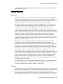
1
Overview of the D-Link Unified Access
System
The D-Link Unified Access System is a wireless local area network (WLAN) solution that
enables WLAN deployment while providing state-of-the-art wireless networking features. It is
a scalable solution that provides secure wireless connectivity and seamless layer 2 and layer 3
roaming for end users.
This chapter contains the following sections:
•
•
•
•
D-Link Unified Access System Components
D-Link Unified Access System Topology
Understanding the User Interfaces
Wireless System Features and Standards Support
D-Link Unified Access System Components
The D-Link Unified Access System components include the D-Link WLAN Controller Switch
and the D-Link Access Point (AP).
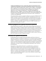
Each D-Link WLAN Controller Switch can manage up to 48 D-Link Access Points, and each
access point can handle up to 512 associated wireless clients (256 per radio). The switch tracks
the status and statistics for all associated WLAN traffic and devices.
You can configure up to four peer D-Link WLAN Controller Switches that share various
information about APs and their associated wireless clients. The peer WLAN switches can be
directly connected to each other, separated by layer 2 bridges, or located in different IP
subnets. Wireless clients can roam among the access points managed by peer switches without
losing network connections.
Whether or not you have a peer group, the D-Link Unified Access System can support a total
of 8000 wireless clients.
D-Link WLAN Controller Switch
The D-Link WLAN Controller Switch (WCS) handles Layer 2, 3, and 4 switching and routing
functions for traffic on the wired and wireless LAN and manages up to 48 access points (APs).
D-Link Unified Access System Components
19
D-Link Unified Access System User Manual
The WCS user interface allows you to configure and monitor all AP settings and maintain a
consistent configuration among all APs in the network.
The WCS supports advanced data path connectivity, mobility control, security safeguards,
control over radio and power parameters, and management features for both network and
element control. The WCS allows you to control the discovery, validation, authentication, and
monitoring of peer wireless switches, D-Link Access Points, and clients on the WLAN,
including discovery and status of rogue APs and clients.
The D-Link Unified Access System works with the following D-Link switches:
•
•
DWS-3024 (24 GE ports)
DWS-3026 (24 GE ports + 2 10G ports)
D-Link Access Point
The D-Link Access Point is part of the D-Link Unified Access System, and you manage it by
using the D-Link WLAN Controller Switch.
By using the WCS to manage the access points, you can centralize AP management and
streamline the AP upgrade process by pushing configuration profiles and software upgrades
from the WCS to the managed APs.
The D-Link Unified Access System works with the following D-Link access points:
•
•
DWL-3500AP
DWL-8500AP
The DWL-3500AP supports one radio, and the DWL-8500AP supports two radios. The DWL3500AP radio and one of the DWL-8500AP radios operate in IEEE 802.11g mode. The
second radio on the DWL-8500AP operates in IEEE 802.11a mode.
Each access point supports up to eight virtual access points (VAPs) on each radio. The VAP
feature allows you to segment each physical access point into eight logical access points (per
radio) that each support a unique SSID, VLAN ID, and security policy.
WLAN Visualization
The D-Link Unified Access System includes the WLAN Visualization tool, which provides a
graphical representation of your wireless network through a Web browser. WLAN
Visualization detects and displays the D-Link WLAN Controller Switch, D-Link Access
Points, other access points, and all wireless clients associated with the D-Link Access Point.
You can import information about your building layout to customize the network view.
20
© 2001- 2006 D-Link Corporation/D-Link Systems, Inc. All Rights Reserved.
1 Overview of the D-Link Unified Access System
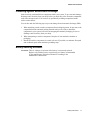
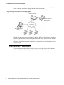
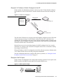
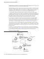
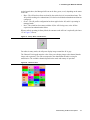
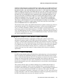
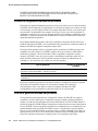
Figure 1 shows an example of a floor plan and network with a D-Link WLAN Controller
Switch that manages two APs. The graph also shows a peer switch and a rogue AP in the
network.
Figure 1. Sample WLAN Visualization
The WLAN Visualization tool provides an AP power display with color-coded channels to
help you determine where to physically place access points to reduce interference or increase
coverage on your WLAN.
D-Link Unified Access System Topology
The WLAN network topology you use depends on the size and requirements of your network.
Small-to-medium networks might require only one WCS that manages a few D-Link Access
Points. For larger networks that need greater roaming capabilities for wireless clients, a
deployment with multiple peer switches that each manage several APs might be appropriate.
Single WCS Deployment
When you deploy a D-Link Access Point, the D-Link WLAN Controller Switch can
automatically detect the AP and assign a default profile, which includes automatic RF channel
D-Link Unified Access System Topology
21
D-Link Unified Access System User Manual
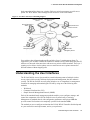
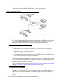
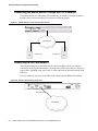
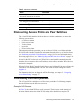
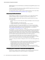
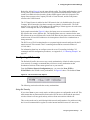
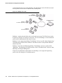
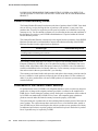
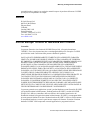
selection and automatic power adjustment. Figure 2 shows a deployment with one D-Link
WLAN Controller Switch that manages three D-Link Access Points.
Figure 2. Single WCS with Layer 2 Roaming Support
Wireless Controller
Switch
Terminal with Direct
Serial Connection
L2 Network
Remote Management
Station
AP 1
AP 2
AP 3
When the APs are on the same subnet and have the same SSID, wireless clients can seamlessly
roam among the three APs with no interruption in network access. The client keeps the same
IP address and does not need to re-authenticate when it moves into the broadcast area of a
different AP. Configuration changes to the APs are managed by the switch simultaneously or
on a per-AP basis.
Peer Switch WCS Deployment
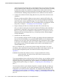
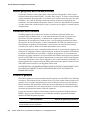
To support larger networks, you can configure up to four switches as peers, which increases
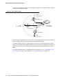
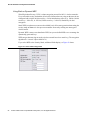
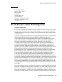
the size and range of the WLAN. Figure 3 shows a D-Link Unified Access System
22
© 2001- 2006 D-Link Corporation/D-Link Systems, Inc. All Rights Reserved.
1 Overview of the D-Link Unified Access System
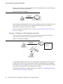
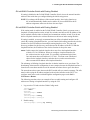
deployment that utilizes three peer switches. Each peer switch can manage up to 48 access
points. The WCS and the APs it manages do not need to be on the same subnet.
Figure 3. Peer WCS with Layer 3 Roaming Support
Wireless Controller
Switch 1
Wireless Controller
Switch 2
Remote Management
Station
Terminal with Direct
Serial Connection
L3 Network
Wireless Controller
Switch 3
Access Points
Managed by WCS 1
Access Points
Managed by WCS 3
Access Points
Managed by WCS 2
Peer switches share information about APs and allow Layer 3 roaming among them. To
support this, peer switches establish IPv4 tunnels so that the wireless client keeps the same IP
address even when the client associates with an access point in a different subnet. The Layer 3
roaming service allows wireless phone users to roam between access points connected to
different subnets without dropping calls.
Understanding the User Interfaces
The D-Link Unified Access System enables centralized management of multiple wireless
access points, which not only facilitates deployment and management, but also enhances
security. The D-Link Unified Access System includes a set of comprehensive management
functions for managing and monitoring the WLAN by using one of the following three
methods:
•
•
•
Web-based
Command-Line Interface (CLI)
Simple Network Management Protocol (SNMP)
Each of the standards-based management methods enables you to configure, manage, and
control the components of the D-Link Unified Access System locally or remotely.
Management is standards-based, with configuration parameters and a private MIB that
provides control for functions not completely specified in the standard MIBs.
The method you use to configure and monitor the D-Link WLAN Controller Switch depends
on your network size and requirements, and on your preference.
Understanding the User Interfaces
23
D-Link Unified Access System User Manual
Using the Web Interface
To access the switch by using a Web browser, the browser must meet the following software
requirements:
•
•
•
HTML version 4.0, or later
HTTP version 1.1, or later
JavaScriptTM version 1.5, or later
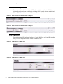
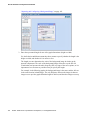
Use the following procedures to log on to the Web Interface:
1. Open a Web browser and enter the IP address of the switch in the Web browser address
field.
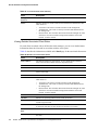
2. Click Login when the Login screen displays.
3. Enter the user name and password into the dialogue box that appears.
The user name and password are the same as those you use to log on to the command-line
interface. By default, the user name is admin, and there is no password.
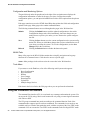
4. After the system authenticates you, the System Description page displays.
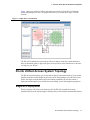
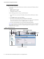
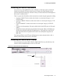
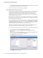
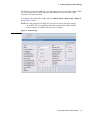
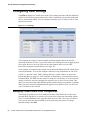
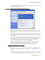
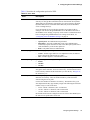
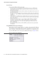
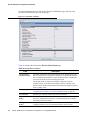
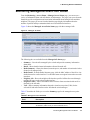
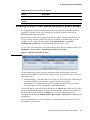
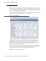
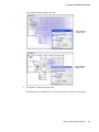
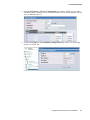
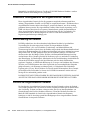
Figure 4 shows the layout of the D-Link WLAN Controller Switch Web interface. Each Web
page contains three main areas: interface configuration graphic, the navigation tree, and the
configuration status or options.
Figure 4. Web Interface Layout
LAN and WLAN Tabs
Tools Menu
Interface Configuration Graphic
WLAN Tabs
Help Page
Access
Navigation Tree
Configuration Status and Options
24
© 2001- 2006 D-Link Corporation/D-Link Systems, Inc. All Rights Reserved.
1 Overview of the D-Link Unified Access System
Interface Configuration Graphic
The interface configuration graphic is a Java™ applet that displays the ports on the D-Link
WLAN Controller Switch. This graphic appears at the top of each page to provide an alternate
way to navigate to configuration and monitoring options.
Click the port you want to view or configure to see a menu that displays statistics and
configuration options. Click the menu option to access the page that contains the configuration
or monitoring options.
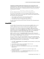
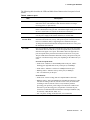
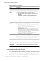
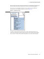
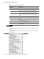
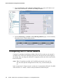
If you click the graphic but do not click a specific port, the main menu appears. This menu
contains the same option as the navigation menu on the left side of the page.
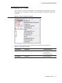
Figure 5. Cascading Navigation Menu
Navigation Menu
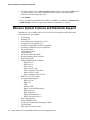
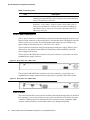
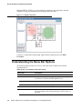
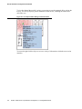
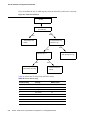
A hierarchical-tree view appears to the left of the panel. The tree consists of a combination of
folders, subfolders, and configuration and status HTML pages. Click the folder to view the
options in that folder. Each folder contains either subfolders or HTML pages, or a combination
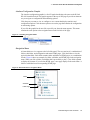
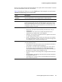
of both. Figure 6 shows an example of a folder, subfolder, and HTML page in the navigation
menu. When you click a folder or subfolder that is preceded by a plus (+), the folder expands
to display the contents. If you click an HTML page, a new page displays in the main frame. A
folder or subfolder has no corresponding HTML page.
Figure 6. Hierarchical Tree Navigation Menu
Folder
Subfolder
HTML Page
Understanding the User Interfaces
25
D-Link Unified Access System User Manual
Configuration and Monitoring Options
The panel directly under the graphic and to the right of the navigation menu displays the
configuration information or status for the page you select. On pages that contain
configuration options, you can input information into fields or select options from drop-down
menus.
Each page contains access to the HTML-based Help that explains the fields and configuration
options for the page. Many pages also contain command buttons.
The following command buttons are used throughout the pages in the Web interface:
Submit
Clicking the Submit button sends the updated configuration to the switch.
Configuration changes take effect immediately, but some changes are not
retained across a power cycle unless you save them to the system configuration file.
Save
Clicking the Save button saves the current configuration to the system configuration file. When you click Save, changes that you have submitted are saved
even when you reboot the system. To save the configuration, use the Save
Changes link in the Tools menu.
Refresh
Clicking the Refresh button refreshes the data on the panel.
WLAN Tabs
Many of the pages in the WLAN folder contain tabs to simplify navigation and to group
functions for a common feature. Click the tab to access a specific page.
NOTE: Other packages in the software suite do not use tabs in the Web interface.
Tools Menu
If you mouse over the Tool icon, a list of the following useful system tools appears:
•
•
•
•
•
•
•
Reset Configuration
Reset Password
REboot
Save Changes
Download File
Upload File
Multiple Image Services
Each item in the list is a link to the Web page where you can perform the related task.
Using the Command-Line Interface
The command-line interface (CLI) is a text-based way to manage and monitor the system. You
can access the CLI by using a direct serial connection or by using a remote logical connection
with Telnet or SSH.
The CLI groups commands into modes according to the command function. Each of the
command modes supports specific software commands. The commands in one mode are not
available until you switch to that particular mode, with the exception of the User EXEC mode
commands. You can execute the User EXEC mode commands in the Privileged EXEC mode.
26
© 2001- 2006 D-Link Corporation/D-Link Systems, Inc. All Rights Reserved.
1 Overview of the D-Link Unified Access System
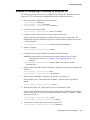
To display the commands available in the current mode, enter a question mark (?) at the
command prompt. To display the available command keywords or parameters, enter a
question mark (?) after each word you type at the command prompt. If there are no additional
command keywords or parameters, or if additional parameters are optional, the following
message appears in the output:
<cr>
Press Enter to execute the command
For more information about the CLI, see the D-Link CLI Command Reference.
The D-Link CLI Command Reference lists each command available from the CLI by the
command name and provides a brief description of the command. Each command reference
also contains the following information:
•
•
•
The command keywords and the required and optional parameters.
The command mode you must be in to access the command.
The default value, if any, of a configurable setting on the device.
The show commands in the document also include a description of the information that the
command shows.
Using SNMP
For D-Link WLAN Controller Switch software that includes the SNMP module, you can
configure SNMP groups and users that can manage traps the SNMP agent generates.
The D-Link WLAN Controller Switch uses both standard public MIBs for standard
functionality as well as a number of additional private MIBs for additional functionality
supported by the switch. All private MIBs begin with a “DLINK-” prefix. The main object for
interface configuration is in DLINK-SWITCHING-MIB, which is a private MIB. Some
interface configurations also involve objects in the public MIB, IF-MIB.
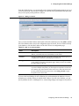
SNMP is enabled by default. The System Description Web page, which is the page the
displays after a successful login, and the show sysinfo command display the information you
need to configure an SNMP manager to access the switch.
Any user can connect to the switch using the SNMPv3 protocol, but for authentication and
encryption, you need to configure a new user profile. To configure a profile by using the CLI,
see the SNMP section in the D-Link CLI Command Reference. To configure an SNMPv3
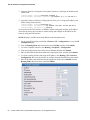
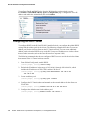
profile by using the Web interface, use the following steps:
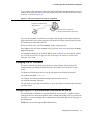
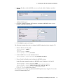
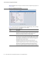
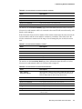
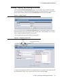
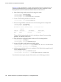
1. Select LAN > Administration > User Accounts from the hierarchical tree on the left side
of the Web interface.
2. Using the User pull-down menu, select Create to create a new user.
3. Enter a new user name in the User Name field.
4. Enter a new user password in the Password field and then retype it in the Confirm
Password field.
To use SNMPv3 Authentication for this user, set a password of eight or more
alphanumeric characters.
5. To enable authentication, use the Authentication Protocol pull-down menu to select
either MD5 or SHA for the authentication protocol.
Understanding the User Interfaces
27
D-Link Unified Access System User Manual
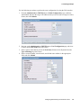
6. To enable encryption, use the Encryption Protocol pull-down menu to select DES for the
encryption scheme. Then, enter an encryption code of eight or more alphanumeric
characters in the Encryption Key field.
7. Click Submit.
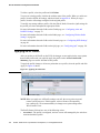
To access configuration information for SNMPv1 or SNMPv2, click LAN > Administration
> SNMP Manager and click the page that contains the information to configure.
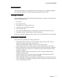
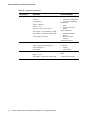
Wireless System Features and Standards Support
In addition to core switching features, the D-Link WLAN Controller Switch supports the
following features and standards:
•
•
•
•
•
•
•
•
•
•
•
•
•
•
•
•
•
•
•
•
28
IP Tunneling
Spanning Tree
Auto detection and configuration of APs
Automatic Peer-Switch Discovery
Automatic or Manual RF Channel Assignment
Automatic or Manual AP Power Adjustment
AP Authentication
Client Authentication
Load Balancing
RF Scan and AP Sentry Mode
Broadcast/Multicast Rate Limiting
Dual Radio Support
Multiple Mode Support for Radios:
- IEEE 802.11a
- IEEE 802.11b
- IEEE 802.11g
- Atheros Turbo 5 Ghz
- Atheros Dynamic Turbo 5Ghz
- Atheros Turbo 2.4 Ghz
- Atheros Dynamic Turbo 2.4 Ghz
IEEE 802.11h (TPC & DFS)
Security Standard Support:
- WEP (64, 128)
- WEP (152)
- TKIP
- AES & CCMP
- Inhibit / Ignore SSID broadcast
- WPA (Personal)
- WPA (Enterprise)
- WPA2 (Personal) 802.11i
- WPA2 (Enterprise) 802.11i
MAC Authentication
Multiple BSSID/VLANs
Security and Authentication Settings per SSID
VLAN Support
IEEE 802.11d (Country Code)
© 2001- 2006 D-Link Corporation/D-Link Systems, Inc. All Rights Reserved.
1 Overview of the D-Link Unified Access System
•
•
•
•
•
•
•
•
•
•
IEEE 802.11e (WMM)
RADIUS support
WLAN Visualization (NMS like product for APs)
Mobility
- Inter- and Intra- Subnet Fast Roaming
- Key caching
- Tunneled and distributed forwarding
- Peer-to-peer WLAN switch roaming
Intrusion Detection
- Rogue AP detection
- Rogue Client detection
- Station blacklisting
- Ad-hoc network detection
Network Management
- SNMP v1, v2c, v3
- CLI
- SYSLOG
- Up to 48 APs per switch
- Auto AP image download
- D-Link WLAN Private MIB
Simultaneous AP upgrade
Centralized data forwarding via tunneling for fast roaming and unified QoS
AP RF Monitoring
Configuration & Firmware Upload/Download
Each AP supports 8 virtual access points (VAPs) per radio. You can configure a unique SSID
and security policy on each VAP. The following list shows some of the D-Link Access Point
features and standards support:
•
•
WLAN and IEEE Standards
- IEEE 802.11a
- IEEE 802.11b
- IEEE 802.11d
- IEEE 802.11e (WMM)
- IEEE 802.11g
- IEEE 802.11h
- IEEE 802.11i (WPA2)
- IEEE 802.1X - 2001 Port Based Network Access Control
- IEEE802.3af PoE Support
WLAN RF Features
- RF Scan
- Transmit Power Control
- Load Balancing
- Dynamic Channel Assignment
- Dual Radio Support
- Atheros Turbo 5 Ghz
- Atheros Dynamic Turbo 5Ghz
- Atheros Turbo 2.4 Ghz
- Atheros Dynamic Turbo 2.4 Ghz
- TELEC 4.9GHZ 802.11a modes
Wireless System Features and Standards Support
29
D-Link Unified Access System User Manual
•
•
•
30
- Wireless Statistics
- Virtual AP with Multiple BSSIDs/SSIDs
WLAN AP Management
- CLI Management (SSH)
- Web Management (SSL support)
- SNMP v1/v2
- SNMP v3
- Import and Export of AP Configuration files
- TFTP
- 802.11 MIB
- IF MIB
- Bridge MIB
- D-Link AP Enterprise MIB
WLAN Networking and QoS
- Switch/AP Discovery
- Tunneling
- WMM (802.11e)
- 802.1p (MAC layer QoS support)
- DSCP
- Dynamic VLANs
- MAC ACLs
- SpectralLink Priority Support
- Broadcast/Multicast Rate Limiting
WLAN Encryption and Security
- WEP
- TKIP
- AES & CCMP
- Rogue AP detection
- Ad-Hoc Client Detection
- Inhibit / Ignore SSID broadcast
- Weak IV avoidance
- MAC Authentication
- Port/IP blocking
- RADIUS support
- EAP
- PEAP
- TLS and TTLS
- WPA (Personal, Enterprise)
- WPA2 (Personal, Enterprise) 802.11i
- 802.1x Supplicant
- Client Authentication
- Inter AP client privacy
- Firewall/IP filtering support
© 2001- 2006 D-Link Corporation/D-Link Systems, Inc. All Rights Reserved.
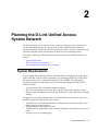
2
Planning the D-Link Unified Access
System Network
The D-Link Unified Access System provides continuous, high-speed access between your
wireless and Ethernet devices. It is an advanced, scalable, standards-based solution for
wireless networking. The D-Link Unified Access System enables wireless local area network
(WLAN) deployment while providing state-of-the-art wireless networking features.
This chapter contains the following sections to help you plan your D-Link Unified Access
System:
•
•
•
System Requirements
WLAN Topology Considerations
Network Planning to Support Layer 3 Roaming
System Requirements
You accomplish the initial D-Link WLAN Controller Switch configuration by using a direct
cable connection. After the initial configuration, you can manage the WCS by using a Webbased user interface (UI), command line interface (CLI), or SNMP. The following list
describes the minimum requirements you need to install and manage the D-Link WLAN
Controller Switch:
•
•
•
VT100 terminal or PC with terminal-emulation software
Direct serial connection to the console port of the D-Link WLAN Controller Switch
Remote system for management access with a Web browser, Telnet/SSH client, or SNMP
manager
To support security and networking features in D-Link Unified Access System, you can use
the following optional equipment on your network:
•
•
•
•
A RADIUS server for authentication and accounting features for wireless clients, access
points, and peer wireless switches
Network equipment that supports VLANs
A DHCP server to dynamically assign network information to the switch and to all access
points
A Syslog server for external logging
System Requirements
31
D-Link Unified Access System User Manual
Figure 7 shows a simple D-Link Unified Access System deployment with required and
optional equipment for setup and operation.
Figure 7. D-Link Unified Access System Components
Wireless Controller
Switch
AP 1
Terminal with Direct
Serial Connection
Network
AP 2
Remote Management
Station
AP 3
RADIUS Server
DHCP Server
Syslog Server
Wireless Clients
NOTE: The D-Link WLAN Controller Switch has a built-in DHCP server. If you do
not already have a DHCP server on your network, you can configure the WCS
to assign network information to network hosts.
As the figure shows, the wireless clients can be laptop computers, personal digital assistants
(PDAs), smart phones, or any other hand-held, portable or stationary device equipped with a
Wi-Fi adapter and supporting drivers. In order to connect to the access point, wireless clients
need the software and hardware the following list describes:
•
•
•
A portable or built-in Wi-Fi client adapter that supports one or more of the IEEE 802.11
modes in which you plan to run the access point. (IEEE 802.11a, 802.11b, 802.11g)
Client software such as Microsoft Windows Supplicant configured to associate with the
WLAN.
Wireless security software that is compatible with the authentication mode the access
point uses.
WLAN Topology Considerations
The D-Link WLAN Controller Switch adds WLAN functionality to the base switching and IP
routing features standard in most Layer 2/3 switches. Where you put the D-Link WLAN
Controller Switch in your network depends on the size, requirements, and existing topology of
your network. If you are adding a wireless network to an existing network, your requirements
are different than the requirements of someone who does not have a sufficient LAN
infrastructure.
32
© 2001- 2006 D-Link Corporation/D-Link Systems, Inc. All Rights Reserved.
2 Planning the D-Link Unified Access System Network
Since the D-Link WLAN Controller Switch has Layer 2/3 switching functions as well as
WLAN data and management functions, you can connect D-Link Access Points, wired PCs, or
other network equipment such as hubs, routers, or other switches directly to the 10/100 Mbps
Ethernet ports on the switch. All connections to the D-Link WLAN Controller Switch must be
wired connections since the switch does not have any radios.
In Figure 8, the D-Link WLAN Controller Switches are both LAN and WLAN switches that
handle traffic from end users connected to the wired LAN as well as traffic from the D-Link
Access Points. In the diagram, Building 1 and Building 2 have a D-Link WLAN Controller
Switch on each floor.
Figure 8. Wiring Closet Topology
Building 1
Floor 2
WCS
Building 2
Floor 2
WCS
L2/L3 Distribution Switch
APs
Building 1
Floor 1
APs
WCS
WCS
Building 2
Floor 1
To Network
Backbone
APs
APs
The four D-Link WLAN Controller Switches are in the same peer group. This allows wireless
clients to roam between floors and between buildings without the need to re-authenticate.
Additionally, each WCS shares its list of managed APs and wireless clients with the switches
in the peer group so that the APs and wireless clients are not reported as rogues (unknown).
The topology in Figure 8 works well if you need to add, upgrade, or replace LAN switches on
your network.
WLAN Topology Considerations
33
D-Link Unified Access System User Manual
Figure 9 shows two D-Link WLAN Controller Switches in the network data center. In this
deployment, the switches do not connect directly to APs or end-user nodes.
Figure 9. Data Center Topology
LAN Switch
APs
WCS
Network
Backbone
WCS
Data Center
LAN Switch
APs
The data center topology is a good solution in networks where the goal is to add a wireless
LAN to a network with minimal changes to the existing network. Traffic from wireless clients
to the APs is either tunneled through the WCS or tagged with a VLAN ID by the AP and
handled accordingly. If the traffic is tagged, it might not pass through the WCS.
Access Point-to-Switch Discovery
To enable the AP and WCS to discover each other, you can use one of the following four
methods:
•
•
•
•
Enter the IP address of the WCS into the AP
Enter the IP address of the AP into the WCS
Configure the DHCP server to pass the IP address of the WCS to the AP in DHCP option 43
Use the D-Link Wireless Device Discovery Protocol
The AP-to-switch discovery method you use depends on your network topology. For example,
if the WCS and AP are in the same Layer 2 multicast domain, we recommend that you use the
D-Link Wireless Device Discovery Protocol.
These options are discussed in more detail in “Discovering Access Points and Peer Switches”
on page 11“Discovering Access Points and Peer Switches” on page 57.
Access Point Placement
D-Link Access Points can be on the same subnet as the switch or on a different subnet. You
can connect the AP directly to the WCS or to another networking device. The range of the
D-Link Access Point is about 100 meters, but the range is affected by various environmental
factors.
34
© 2001- 2006 D-Link Corporation/D-Link Systems, Inc. All Rights Reserved.
2 Planning the D-Link Unified Access System Network
To maximize the range, use the following guidelines for the placement of the AP:
•
•
•
•
•
•
Place the AP in an area where you expect wireless clients will operate.
Elevated locations, such as on top of a shelf are preferred to increase line-of-sight access.
Avoid placing the AP near sources of interference, such as PCs, microwaves, and 2.4 GHz
cordless phones.
Keep the AP away from large metal surfaces.
Position the antenna horizontally to increase the up-and-down range, or position it
vertically to increase side-to-side coverage.
When APs are within broadcast range of each other, use non-interfering RF channels (five
channels apart for the 802.11b/g radio).
How close you place APs to each other depends on the RF transmission power level, the
number of wireless clients on your network, and the channels the APs use. The RF signal
transmission power level directly affects the broadcast range of the AP signal. If the power
level is too low, wireless clients will not detect the signal or experience poor WLAN
performance. If the power level is too high, the RF signal might interfere with other APs
within range. If the RF signal broadcasts beyond the physical confines of your building or
network, it increases the security threat to the network.
When the power level is high and RF broadcast area is larger, more wireless clients can detect
the signal and associate with the AP. An increase in the number of wireless clients that
associate with the AP generally means that the amount of traffic the AP receives and transmits
increases as well. You can limit the network utilization level allowed on an AP to prevent
wireless clients from experiencing slower network speeds. However, once the network
utilization is reached, new clients are unable to associate with the AP. If an AP frequently
reaches the network utilization limit, it might indicate that you should add another AP nearby.
You can configure the APs to automatically adjust the power and channel to the needs of the
network environment.
Network Planning to Support Layer 3 Roaming
With the D-Link Unified Access System, mobile stations can maintain their IP connections
while roaming from one access point to another even when these access points are attached to
different IP subnets. This feature enables Voice over IP (VoIP) deployments on 802.11
subnetted networks.
It is often necessary to subdivide the enterprise IPv4 network into several subnets. An access
point may be directly attached to the wireless switch or it may be located several router hops
away from the wireless switch.
To support layer 3 roaming, the switch uses IP tunneling to establish a link between itself and
the access point it manages. The switch routes all IPv4 unicast frames so that the wireless
networks are perceived as locally attached networks by the wireless switch. Routing must be
enabled on the switch to support L3 roaming.
Figure 10 shows a single wireless client as it roams among three APs in three different
subnets. A D-Link WLAN Controller Switch controls the three APs. When the wireless client
connects to any of the APs, it receives an IP address from the WCS that is in the L3 Tunnel
subnet. As the client roams among the APs, it maintains its connection to the WLAN and
Network Planning to Support Layer 3 Roaming
35
D-Link Unified Access System User Manual
keeps the same IP address that the switch originally assigned it. All traffic the client sends and
receives goes through the switch.
Figure 10. Inter-Subnet Roaming
Client
IP: 10.20.20.12
AP 1
IP: 192.168.24.173
WCS
Client
IP: 10.20.20.12
L3 Tunnel Subnet
IP: 10.20.20.0
AP 2
IP: 192.168.38.66
AP 3
IP: 192.168.85.49
Client
IP: 10.20.20.12
In the tunneling configuration, you can use ACL lists and QoS parameters to ensure that timesensitive traffic, such as VoIP, takes priority over other WLAN traffic.
For many IP phone systems, you must connect a call server to a wired port on the L3 tunnel
subnet. You must also either configure DHCP relay on the switch or configure the switch to be
a DHCP server. APs, peer switches, and other routers cannot be connected to the L3 tunnel
subnet.
For more information about L3 tunnelling and how to configure it, see “Configuring a VAP
for L3 Tunnels” on page 91 and Appendix C, “L3 Roaming Example” on page 187.
36
© 2001- 2006 D-Link Corporation/D-Link Systems, Inc. All Rights Reserved.
3
Installing the Hardware
This chapter provides instructions for installing the D-Link DWS-3024 and DWS-3026 switch
hardware. The following sections describe this installation process:
•
•
•
Hardware Overview
- Front Panel Components
- LED Indicators
- Rear Panel Description
- Side Panels
Installation
- Package Contents
- Installation Guidelines
- Installing the Switch without the Rack
- Installing the Switch in a Rack
- Powering On the Switch
- Installing the SFP ports
- Installing the Optional Module
- Connecting to the External Redundant Power System
Connecting the Switch
- Connecting the Switch to the Network
- Connecting the Switch and AP Directly
- Connecting the Switch and AP through the L2/L3 Network
- Connecting to the Core Network
Hardware Overview
This section describes the font, back, and side panels and the LED indicators on the switch.
The DWS-3024 and DWS-3026 have slightly different front and back panels based on the
available features.
Hardware Overview
37
D-Link Unified Access System User Manual
Front Panel Components
The front panel of the Switch consists of LED indicators for Power, Console, RPS, PoE, and
Link/Act/Speed for each port on the Switch including 10GE Ports for optional modules and
SFP port LEDs. Table 2 describes the LED indicators in more detail.
Figure 11. Front Panel View of the DWS-3024 as Shipped
Figure 12. Front Panel View of the DWS-3026 as Shipped
LED Indicators
The Switch supports LED indicators for Power, Console, RPS, PoE, and Port LEDs including
10GE port LEDs for optional module inserts on the DWS-3026.
Figure 13. LED Indicators on DWS-3024
Figure 14. LED Indicators on DWS-3026
38
© 2001- 2006 D-Link Corporation/D-Link Systems, Inc. All Rights Reserved.
3 Installing the Hardware
The following table describes the LEDs and Mode Select Button on the front panel of each
Switch.
Table 2. LED Description
LED
Description
Power
This LED lights green after powering the Switch on to indicate the ready
state of the device. The indicator is dark when the Switch is no longer
receiving power (i.e powered off).
Console
This LED blinks green during the Power-On Self Test (POST). When the
POST is finished, the LED goes dark. The indicator lights steady green when
an active console link is in session via the RS-232 console port.
RPS
This LED lights when the internal power has failed and the RPS has taken
over the power supply to the Switch. Otherwise, it remains dark.
Link/Act/Speed
and PoE Mode
You can change the mode of the LEDs over each port to display the
information about the link, activity, and speed of a port or whether 802.3af
Power Over Ethernet (PoE) is supporting devices attached to the port.
To change the LED mode from Link/Act/Speed to PoE and vice versa, press
the LED Mode Select Button.
Port LEDs
One row of LEDs for each port is located above the ports on the front panel.
The indicator above the left side of a port corresponds to the port below the
indicator in the upper row of ports. The indicator above the right side of a
port corresponds to the port below the indicator in the lower row of ports.
The port LEDs show information about link, activity, and speed on the port
or Power over Ethernet usage on the port, depending on the LED mode you
select.
For Link/Act/Speed Mode:
• Solid Green—Indicates a valid 1000Mbps link on the port, while a
blinking green light indicates activity on the port (at 1000Mbps).
• Solid Amber—Indicates a valid 10 or 100Mbps link on the port.
• Blinking Amber—Indicates activity on the port (at 100Mbps).
• Off—No link/activity on the port.
For PoE Mode:
• Solid Green—Power feeding (802.3af-compliant PD was detected).
• Blinking Amber—PoE port ERROR (non-standard PD connected, Under
load state according to 802.3af (current is below I min), Overload state
according to 802.3af (current is above I cut), hardware problems
preventing port operation, power budget exceeded, short condition was
detected at a port delivering power, temperature overload at the port,
succession of Underload and Overload states caused port shutdown (may
be caused by a PD's DC/DC fault)...etc.)
• Off—No power feeding (no PD detected, or no connection)
Hardware Overview
39
D-Link Unified Access System User Manual
Table 2. LED Description
LED
Description
10GE Port LEDs
(DWS-3026 only) A steady green light denotes a valid link on the port while
a blinking green light indicates activity on the port. These LEDs remain dark
if there is no link/activity on the port.
Combo SFP Ports
The LED indicators for the Combo ports are located above the ports and
numbered 1 – 4 for Combo 1, Combo 2, Combo 3, and Combo 4 ports. A
steady green light indicates a valid link on the port while a blinking green
light indicates activity on the port. These LEDs remain dark if there is no
link/activity on the port.
Rear Panel Description
The AC power connector is a standard three-pronged connector that supports the power cord.
Plug the female connector of the provided power cord into this socket, and plug the male side
of the cord into a power outlet. The Switch automatically adjusts its power setting to any
supply voltage in the range from 100 ~ 240 VAC at 50 ~ 60 Hz.
The rear panel also includes an outlet for an optional external power supply. When a power
failure occurs, the optional external RPS will immediately and automatically assume the
power supply for the Switch.
The rear panel of the DWS-3024 contains an AC power connector, a system fan vent, and a
redundant power supply connector.
Figure 15. Rear panel view of DWS-3024
The rear panel of the DWS-3026 contains an AC power connector, a system fan vent, a
redundant power supply connector and two empty slots for optional 10GE module inserts.
Figure 16. Rear panel view of DWS-3026
Side Panels
The system fans and heat vents located on each side of the Switch dissipate heat. Do not block
these openings. Leave at least 6 inches of space at the rear and sides of the Switch for proper
ventilation. Without proper heat dissipation and air circulation, system components might
overheat, which could lead to system failure and severely damage components.
40
© 2001- 2006 D-Link Corporation/D-Link Systems, Inc. All Rights Reserved.
3 Installing the Hardware
Installation
This section describes how to install the Switch on a flat surface or in a standard equipment
rack. It also describes how to install the optional components for the Switch.
Package Contents
Open the shipping carton of the Switch and carefully unpack its contents. The carton should
contain the following items:
1.
2.
3.
4.
5.
6.
7.
One Switch
One AC power cord
Mounting kit (two brackets and screws)
Four rubber feet with adhesive backing
RS-232 console cable
One CD Kit for DWS-3000 Series Administrator’s Guide and CLI Reference Guide
Registration card & China Warranty Card (for China only)
If any item is missing or damaged, please contact your local D-Link Reseller for replacement.
Installation Guidelines
Please follow these guidelines for setting up the Switch:
•
•
•
•
•
•
•
Install the Switch on a sturdy, level surface that can support at least 6.6 lb. (3 kg) of
weight. Do not place heavy objects on the Switch.
The power outlet should be within 1.82 meters (6 feet) of the Switch.
Visually inspect the power cord and see that it is fully secured to the AC power port.
Make sure that there is proper heat dissipation from the Switch and adequate ventilation
around the Switch. Leave at least 10 cm (4 inches) of space at the front and rear of the
Switch for ventilation.
Install the Switch in a fairly cool and dry place for the acceptable temperature and
humidity operating ranges.
Install the Switch in a site free from strong electromagnetic field generators (such as
motors), vibration, dust, and direct exposure to sunlight.
When installing the Switch on a level surface, attach the rubber feet to the bottom of the
device. The rubber feet cushion the Switch, protect the casing from scratches, and prevent
it from scratching other surfaces.
Installation
41
D-Link Unified Access System User Manual
Installing the Switch without the Rack
First, attach the rubber feet included with the Switch if installing on a desktop or shelf. Attach
these cushioning feet on the bottom at each corner of the device. Allow enough ventilation
space between the Switch and any other objects in the vicinity.
Figure 17. Prepare Switch for Installation on a Desktop or Shelf
Rubber Feet
Installing the Switch in a Rack
The Switch can be mounted in a standard 19" rack. Use the following diagrams as a guide.
Figure 18. Fasten Mounting Brackets to Switch
42
© 2001- 2006 D-Link Corporation/D-Link Systems, Inc. All Rights Reserved.
3 Installing the Hardware
Fasten the mounting brackets to the Switch using the screws provided. With the brackets
attached securely, the Switch can be mounted in a standard rack as shown in Figure 19.
Figure 19. Mounting the Switch in a Standard 19" Rack
Powering On the Switch
Plug one end of the AC power cord into the power connector of the Switch and the other end
into the local power source outlet.
After powering on the Switch, the LED indicators will momentarily blink. This blinking of the
LED indicators represents a reset of the system.
Power Failure
As a precaution, in the event of a power failure, unplug the Switch. When power is resumed,
plug the Switch back in.
Installing the SFP ports
The DWS-3000 series switches are equipped with SFP (Small Form-factor Pluggable) ports,
which are to be used with fiber-optical transceiver cabling in order to uplink various other
networking devices for a gigabit link that may span great distances. These SFP ports support
full-duplex transmissions, have auto-negotiation and can be used with DEM-310GT
(1000BASE-LX), DEM-311GT (1000BASE-SX), DEM-314GT (1000BASE-LH) and DEM-
Installation
43
D-Link Unified Access System User Manual
315GT (1000BASE-ZX) transceivers. See the figure below for installing the SFP ports in the
Switch.
Figure 20. Inserting the Fiber-Optic Transceivers into the Switch
Installing the Optional Module
The rear panel of the DWS-3026 includes two open slots that may be equipped with the DEM410X 1-port 10GE XFP uplink module, or a DEM-410CX 1-port 10GBASE-CX4 uplink
module, both sold separately.
Adding the DEM-410X optional module allows the switch to transmit data at a rate of ten
gigabits per second. The module port(s) are compliant with standard IEEE 802.3ae, support
full-duplex transmissions only and must be used with XFP MSA-compliant transceivers.
The DEM-410CX uses copper wire medium, not optic fiber and therefore has a transmit length
limit up to 1 meters. Compliant with the IEEE802.3ak standard, this module uses a 4-lane
copper connector for data transfer in full-duplex mode.
To install these modules in the DWS-3026 Switch, follow the steps listed in this section.
CAUTION: Before adding the optional module, make sure to disconnect all power
sources connected to the Switch. Failure to do so may result in an
electrical shock, which may cause damage, not only to the individual but
to the Switch as well.
At the back of the Switch to the left are the two slots for the optional modules. These slots
must be covered with the faceplate if the slots are not being used. To install a module in an
available slot, remove the faceplate by loosening the screws and pulling off the plate.
44
© 2001- 2006 D-Link Corporation/D-Link Systems, Inc. All Rights Reserved.
3 Installing the Hardware
The front panels of the available modules are shown here:
Figure 21. Front Panel of the DEM-410X
Figure 22. Front Panel of the DEM-410CX
Install the Module
Unplug the Switch before removing the faceplate covering the empty slot. To install the
module, slide it in to the available slot at the rear of the Switch until it reaches the back, as
shown in the following figure. Gently, but firmly push in on the module to secure it to the
Switch. The module should fit snugly into the corresponding receptors.
Figure 23. Inserting the optional module into the Switch (DWS-3026)
Installation
45
D-Link Unified Access System User Manual
Now tighten the two screws at adjacent ends of the module into the available screw holes on
the Switch. The upgraded Switch is now ready for use.
Figure 24. DWS-3026 with optional DEM-410X module installed
Connecting to the External Redundant Power System
The Switch supports an external redundant power system (RPS). The diagrams below
illustrate a proper RPS power connection to the Switch. Please consult the documentation for
information on power cabling and connectors and setup procedure.
Figure 25. RPS Connector
DWS-3026
DPS-600
RPS Connector
Connecting the Switch
This section describes how to connect the following nodes:
•
•
•
•
Switch to the network
AP directly to the Switch
AP to the Switch through the L2/L3 network
Switch through the 10GB uplink to the network core
NOTE: All 24 high-performance N-Way Ethernet ports can support both MDI-II and
MDI-X connections.
46
© 2001- 2006 D-Link Corporation/D-Link Systems, Inc. All Rights Reserved.
3 Installing the Hardware
Connecting the Switch to the Network
You can use any of the 1000BASE-T ports, 10GB ports, or fiber-optic ports to connect the
Switch to your network. The type of port you use to connect the switch depends on your
network requirements and the type of node to which you connect the Switch, which might be a
hub, router, or another switch.
There is a great deal of flexibility on how connections are made using the appropriate cabling.
•
•
•
•
•
Connect a 10BASE-T hub or switch to the Switch via a twisted-pair Category 3, 4 or 5
UTP/STP cable.
Connect a 100BASE-TX hub or switch to the Switch via a twisted-pair Category 5 UTP/
STP cable.
Connect 1000BASE-T switch to the Switch via a twisted pair Category 5e UTP/STP
cable.
Connect a switch supporting a fiber-optic uplink to the Switch's SFP ports via fiber-optic
cabling.
Change the Switch to PoE mode using the Mode Select button. When in PoE Mode, the
Switch works with all D-Link 802.3af capable devices. The Switch also works in PoE
mode with all non-802.3af capable D-Link AP, IP Cam and IP phone equipment via
DWL-P50.
The Link/Act LEDs for each UTP port will light green or amber when the link is valid. A
blinking LED indicates packet activity on that port.
Connecting the Switch and AP Directly
You can connect one or more DWL-3500AP or DWL-8500AP access points directly to the
Switch by using a straight-through or crossover UTP cable.
Figure 26. Switch and AP Connected Directly
UTP Cable
Access Point
Connecting the Switch
47
D-Link Unified Access System User Manual
Connecting the Switch and AP through the L2/L3 Network
The Switch can discover and manage APs whether they are directly connected, connected
through a device in the same subnet, or connected to different subnets.
Figure 27. Switch and APs Connected Through Network
L2/L3 Network
Access Point
Access Point
Connecting to the Core Network
The optional 10GB ports on the DWS-3026 are ideal for uplinking to the core network.
Connections to the Gigabit Ethernet ports are made using a fiber-optic cable or Category 5e
copper cable, depending on the type of port. A valid connection is indicated when the Link
LED is lit.
Figure 28 shows the rear panel of the DWS-3026 with the optional DEM-410X module.
Figure 28. Switch Connected to Network Core
Fiber Optic Cable
Core Network
48
© 2001- 2006 D-Link Corporation/D-Link Systems, Inc. All Rights Reserved.
4
Installing the D-Link Unified Access
System
This chapter contains the following sections to help you install your D-Link Unified Access
System network:
•
•
•
•
•
•
System Deployment Overview
Connecting the Switch to the Network
Enabling the WLAN Features on the Switch
Preparing the Access Points
Discovering Access Points and Peer Switches
Authenticating and Validating Access Points
System Deployment Overview
To setup and deploy the D-Link Unified Access System solution, use the following general
steps:
1. Plan the WLAN network topology.
Decide where to locate each access point to maximize accessibility to the WLAN by
wireless clients and to minimize radio frequency (RF) interference by other access points.
You should also determine how to integrate the D-Link WLAN Controller Switch into
your existing network topology. For more information about planning the WLAN
topology, see “WLAN Topology Considerations” on page 32.
2. Install and configure the D-Link WLAN Controller Switch.
To install and configure the switch, you need a serial connection to the switch, or you must
connect to the switch from a host in the same subnet as the switch default IP address
(10.10.10.90/8). From the initial connection to the switch, you can configure basic
network information or enable the DHCP client on the switch to acquire this information
automatically.
3. Enable the WLAN switch function and assign an IP address to the WLAN switch
interface.
The WLAN features on the switch are disabled by default. You must enable the WLAN
System Deployment Overview
49
D-Link Unified Access System User Manual
switch in order for the switch to discover and validate D-Link Access Points. If the routing
mode is disabled, the WCS function uses the IP address of the network interface. If routing
is enabled, the switch uses a loopback or routing interface for the wireless functions.
Changing the IP address of the network interface automatically disables and re-enables the
wireless function. Enabling routing also disables and re-enables the wireless function.
4. Configure the default AP Profile settings that the access point will use after the switch
validates it.
When the switch successfully validates an access point, it sends the AP Profile to the
access point. The AP Profile contains all of the access point configuration information,
such as the radio, security, and SSID settings. You can configure all of the AP settings
before or after the switch validates an AP. For information about configuring the default
AP profile, see Chapter 5, “Configuring Access Point Settings” on page 77.
5. Prepare and deploy D-Link Access Points and enable AP-to-switch discovery.
After you connect an AP to the network and it obtains an IP address (either statically or
dynamically by using DHCP), the wireless switch can automatically discover the AP.
However, if your network uses IEEE 802.1x authentication or you require the AP to be
authenticated by the switch upon discovery, you must log on to the AP and configure
security information.
6. Authenticate and validate the APs.
You can optionally configure the WCS so that it only manages APs that it authenticates.
You can use the local database or an external RADIUS database for AP authentication.
Whether or not you require AP-to-WCS authentication, the switch must be able to validate
an AP before it can manage the AP. For the switch to validate the AP, you must add the
MAC address of each AP to the AP database on the switch or to the database on an
external RADIUS server.
Once you validate the AP, you can use the switch to manage the AP and to view client
associations, status, and statistics.If you follow the procedures in this chapter, the APs will
have the default configuration profile. The default AP Profile settings are listed in
Appendix A.
CAUTION: The default AP profile does not use a security mechanism for wireless
client associations. All wireless clients will be able to connect to an AP
and access your network.
To prevent unauthorized access to the network by wireless clients, you can configure security
on the default profile before you deploy the APs, or you can create additional AP profiles to
assign the APs when you add them to the Valid AP database. For information about how to
configure default profile settings, see Chapter 5, “Configuring Access Point Settings” on
page 77.
You can use the switch to create multiple AP profiles to assign the APs that you deploy on
your network. For each profile, you can define information such as RF configuration, QoS
configuration, and virtual AP (VAP) configuration. For information about AP profiles, see
“AP Profiles, Networks, and the Local Database” on page 77. For information about creating
and configuring a new AP profile, see “Creating, Configuring, and Managing AP Profiles” on
page 149.
50
© 2001- 2006 D-Link Corporation/D-Link Systems, Inc. All Rights Reserved.
4 Installing the D-Link Unified Access System
Connecting the Switch to the Network
After you perform the physical hardware installation, you need to connect the D-Link WLAN
Controller Switch to the network. The default IP address of the switch is 10.90.90.90/8, and
DHCP is disabled by default. If you want to enable DHCP on the switch or assign a different
static IP address, you must connect to the switch and change the default settings.
You can connect to the switch through Telnet or a Web browser from a host on the 10.0.0.0/8
network, or you can connect to the switch through the console port (RS-232 DCE). After you
connect to the switch, you can provide network information or enable the DHCP client.
To connect to the switch from a host on the 10.0.0.0 network, enter the default IP address of
the switch (10.90.90.90) into the address field of a Web browser or a Telnet client.
To connect to the console port and provide network information, use the following steps:
1. Using a null-modem cable, connect a VT100/ANSI terminal or a workstation to the
console (serial) port.
If you attached a PC, Apple, or UNIX workstation, start a terminal-emulation program,
such as HyperTerminal or TeraTerm.
2. Configure the terminal-emulation program to use the following settings:
- Baud rate: 115,000 bps
- Data bits: 8
- Parity: none
- Stop bit: 1
- Flow control: none
3. Press the return key, and the User: prompt appears.
Enter admin as the user name. There is no default password. Press ENTER at the password
prompt if you did not change the default password.
After a successful login, the screen shows the (switch-prompt)> prompt.
4. At the (switch-prompt)> prompt, enter enable to enter the Privileged EXEC command
mode. There is no default password to enter Privileged EXEC mode. Press ENTER at the
password prompt if you did not change the default password.
The command prompt changes to (switch-prompt)#.
5. Configure the network information.
- To use a DHCP server to obtain the IP address, subnet mask, and default gateway
information, enter network protocol dhcp.
- To use a BootP server to obtain the IP address, subnet mask, and default gateway
information, enter network protocol bootp.
- To manually configure the IP address, subnet mask, and default gateway, enter
network parms <ipaddress> <netmask> [<gateway>], for example:
network parms 192.168.2.23 255.255.255.0 192.168.2.1
The default gateway is an optional parameter, so you do not need to enter an address
to execute the command.
Connecting the Switch to the Network
51
D-Link Unified Access System User Manual
To view the network information, enter show network.
6. To save these changes so they are retained during a switch reset, enter the following
command:
write
Once the D-Link WLAN Controller Switch is connected to the network, you can use the IP
address for remote access to the switch by using a Web browser or through Telnet or SSH.
Enabling the WLAN Features on the Switch
In order for the WCS to be able to discover and manage access points, the WLAN switch and
its operational status must both be enabled. However, before you enable the WLAN switch, set
the correct country code for the switch so that the access points can only operate in the modes
permitted in your country. The default country code is US for operation in the United States.
To set the country code and enable the switch by using the Web interface, click
Administration > Basic Setup. Table 3 describes the fields on the Wireless Global
Configuration page.
NOTE: Wireless features are available under the WLAN tab on the navigation menu.
NOTE: Most configuration pages have a Submit button, which applies the changes to
the running configuration but does not save them to non-volatile memory
(NVRAM). To make the changes permanent so they persist across a reboot,
click the Tool, then click Save Changes to navigate to the appropriate page.
You can also use the write command in Privileged Exec mode.
Table 3. Basic Wireless Global Configuration
Field
Description
Enable WLAN
Switch
Check the box to enable WLAN switching functionality on the system. Clear
the check box to administratively disable the WLAN switch.
If you clear the check box, all peer switches and APs that are associated with
this switch are disassociated.
Disabling the WLAN switch does not affect non-WLAN features on the
switch, such as VLAN or STP functionality.
WLAN Switch
Operational Status
Shows the operational status of the switch. The status can be one of the
following values:
• Enabled
• Enable-Pending
• Disabled
• Disable-Pending
If the status is pending, click Refresh to refresh the screen.
52
© 2001- 2006 D-Link Corporation/D-Link Systems, Inc. All Rights Reserved.
4 Installing the D-Link Unified Access System
Table 3. Basic Wireless Global Configuration
Field
Description
WLAN Switch
Disable Reason
If the status is disabled, this field appears and one of the following reasons is
listed:
•
•
None—The cause for the disabled status is unknown.
Administrator disabled—The Enable WLAN Switch check box has been
cleared.
• No IP Address—The WLAN interface does not have an IP address.
• No SSL Files—The D-Link WLAN Controller Switch communicates
with the APs it manages by using Secure Sockets Layer (SSL)
connections. The first time you power on the WCS, it automatically
generates a server certificate that will be used to set up the SSL
connections. The SSL certificate and key generation can take up to an
hour to complete.
If routing is enabled on the switch, the operational status might be disabled
due to one of the following reasons:
•
•
No Loopback Interface—The switch does not have a loopback interface.
Global Routing Disabled—Even if the routing mode is enabled on the
WLAN switch interface, it must also be enabled globally for the
operational status to be enabled.
For information about how to configure a loopback interface and enable
routing, see “D-Link WLAN Controller Switch with Routing Enabled” on
page 61.
IP Address
This field shows the IP address of the WLAN interface on the switch. If
routing is disabled, the IP address is the network interface. If routing is
enabled, this is the IP address of the routing or loopback interface you
configure for the WCS features.
AP Authentication
Select the check box to require APs to be authenticated before they can
associate with the switch.
AP MAC
Validation
Select the database to use for AP validation.
•
•
Country Code
Local—If you select this option, you must add the MAC address of each
AP to the local Valid AP database.
RADIUS—If you select this option, you must configure the MAC
address of each AP in an external RADIUS server.
Select the country code for the country where your switch and APs operate.
A popup window asks you to confirm the change.
Wireless regulations vary from country to country. Make sure you select the
correct country code so that your WLAN system complies with the
regulations in your country. Some WLAN modes, such as the Atheros
modes, are not available in some countries.
Changing the country code disables and re-enables the switch. Any channel
and radio mode settings that are invalid for the regulatory domain are reset to
the default values.
The country code (IEEE 802.11d) is transmitted in beacons and probe
responses from the access points.
From the CLI, you can view the same information that is available on the Wireless Global
Configuration page with the show wireless command in Privileged EXEC mode. If you
Enabling the WLAN Features on the Switch
53
D-Link Unified Access System User Manual
need to change the country code, you can view the list of available countries and their twoletter codes with the show wireless country-code command.
The CLI commands to set the country code and enable the WLAN switch are available in
Wireless Config mode. To set the country code, enter country-code <code>. To enable the
WLAN switch, enter enable. The following example shows how to access Wireless Config
mode, set the country code to Canada, and enable the WLAN switch.
(switch-prompt)
(switch-prompt)
(switch-prompt)
(switch-prompt)
#configure
(Config)#wireless
(Config-wireless)#country-code CA
(Config-wireless)#enable
Preparing the Access Points
Depending on your network security requirements, you might need to connect to the access
point CLI and configure some settings before you connect it to the network. By default, the AP
uses untagged VLANs and no security. If your network requires IEEE 802.1x authentication,
you must configure the supplicant information in the AP before you connect to the network.
Also, if you configure the D-Link WLAN Controller Switch to require local AP
authentication, you must connect to the access point CLI and configure a pass phrase. To
prevent wireless clients from having access to the AP management interface, you can create a
management VLAN.
NOTE: The commands you enter on the AP apply the changes to the running
configuration but does not save them to non-volatile memory (NVRAM). To
make the changes permanent so they persist across a reboot, use the saverunning command.
Logging on to the AP
You can access the AP CLI only through Telnet. The default IP address is 10.90.90.91/8, and
DHCP is enabled by default on the D-Link Access Point. When you connect the AP to a
network with a DHCP server, the AP automatically acquires an IP address. If there is no
DHCP server on the network, the AP retains its default IP address of 10.90.90.91/8 until you
assign a static IP address.
For initial configuration with a direct Ethernet connection, make sure your PC has an IP
address in the 10.0.0.0/8 subnet so you can access the AP CLI.
54
© 2001- 2006 D-Link Corporation/D-Link Systems, Inc. All Rights Reserved.
4 Installing the D-Link Unified Access System
To use a direct-cable connection, connect one end of an Ethernet straight-through or crossover
cable to the network port on the access point and the other end of the cable to the Ethernet port
on the PC, as shown in Figure 29.
Figure 29. Ethernet Connection for Static IP Assignment
Crossover or straight-through
cable if your AP
This PC must have an IP address
on the same subnet as the Access Point.)
If you use this method, you will need to reconfigure the cabling for subsequent startup and
deployment of the access point so that the access point is no longer connected directly to the
PC but instead is connected to the LAN.
When you Telnet to the AP CLI the WLAN-AP login: prompt appears.
Enter admin as the user name and admin as the password. After a successful login, the WLANAP# prompt appears.
For information about how to disable the DHCP client on the AP or to set a static IP address,
see “D-Link Access Point” on page 63 in the Assigning the IP Address to Switches and
Managed APs section.
Changing the AP Password
For access to the AP, you need to provide the user name (admin), and a password. We
recommend that you change the default AP password to make access to the device more
secure.
To change the default password, log on to the AP and enter the following command:
set system password <password>
For example, the following command changes the password to test1234.
set system password test1234
The password you type appears in plain text. You are not asked to confirm the password after
you enter it once.
Configuring 802.1x Authentication Information on the AP
On networks that use IEEE 802.1x port-based network access control, a supplicant (client)
cannot gain access to the network until the 802.1x authenticator grants access. If your network
uses 802.1x, you must configure 802.1x authentication information that the AP can supply to
the authenticator.
NOTE: The access point supports MD5 authentication.
Preparing the Access Points
55
D-Link Unified Access System User Manual
Table 4 shows the commands you can use to configure 802.1x supplicant information.
Table 4. IEEE 802.1x Supplicant Commands
Action
Command
View 802.1x supplicant settings
get dot1x-supplicant
Enable 802.1x supplicant
set dot1x-supplicant status up
Disable 802.1x supplicant
set dot1x-supplicant status down
Set the 802.1x user name
set dot1x-supplicant user <name>
Set the 802.1s password
set dot1x-supplicant password <password>
In the following example, the administrator enables the 802.1x supplicant and sets the user
name to wlanAP and the password to test1234.
WLAN-AP# set dot1x-supplicant status up
WLAN-AP# set dot1x-supplicant user wlanAP
WLAN-AP# set dot1x-supplicant password test1234
WLAN-AP# get dot1x-supplicant
Property Value
---------------status
up
user
wlanAP
Configuring AP-to-Switch Authentication Information
You can configure a pass phrase on the AP and on the switch so that only authenticated APs
can associate with the switch. If you do enable AP authentication on the WCS, you must
connect to the access point CLI and configure a pass phrase. This pass phrase must be the
same as the one you configure on the WCS.
To configure the pass phrase on the AP, use the following command:
set managed-ap pass-phrase <phrase>
The pass phrase can be up to 32 alphanumeric characters.
For example, the following command sets the AP-to-WCS authentication pass phrase to
test1234.
WLAN-AP# set managed-ap pass-phrase test1234
For more information about AP-to-WCS authentication and how to configure it on the switch,
see “Configuring AP Authentication” on page 71.
Configuring VLAN Information on the Access Point
The management VLAN is VLAN 1 by default. This VLAN is also the default untagged
VLAN. This means that all traffic, including management traffic, is untagged.
If you want to limit access to the management interface on the access point or if you already
have a management VLAN configured on your network with a different VLAN ID, you can
change the VLAN ID of the management VLAN on the access point from the AP CLI.
56
© 2001- 2006 D-Link Corporation/D-Link Systems, Inc. All Rights Reserved.
4 Installing the D-Link Unified Access System
Table 5. AP VLAN Commands
Action
Command
View management interface
information, including the VLAN ID
get management
Set the management VLAN ID
set management vlan-id <1-4096>
View untagged VLAN information
get untagged-vlan
Enable the untagged VLAN
set untagged-vlan status up
Disable the untagged VLAN
set untagged-vlan status down
Set the untagged VLAN ID
set untagged-vlan vlan-id <1-4096>
Discovering Access Points and Peer Switches
The D-Link WLAN Controller Switch can discover, validate, authenticate, or monitor the
following system devices:
•
•
•
•
•
Peer wireless switches
D-Link Access Points
Wireless clients
Rogue APs
Rogue wireless clients.
This section describes the procedures you use to discover D-Link Access Points and other
D-Link WLAN Controller Switches. For information about the discovery of wireless clients,
see “Monitoring Associated Client Information” on page 138. For more information about
discovering rogue devices, see “Monitoring Rogue and RF Scan Access Points” on page 136.
In order for the WCS to discover other WLAN devices and establish communication with
them, the devices must have their own IP address, must be able to find other WLAN devices,
and must be compatible.
When the D-Link WLAN Controller Switch discovers and validates D-Link Access Points, the
switch takes over the management of the AP. The default AP Profile settings are listed in
Appendix A.
For information about how to change the AP Profile settings, see Chapter 5, “Configuring
Access Point Settings” on page 77.
Understanding the Discovery Methods
The WCS and AP have multiple ways of discovering each other. The following examples
describe different ways the discovery can occur.
Example 1: L2 Discovery
In Figure 30, the AP and WCS are directly connected. The devices are in the same layer 2
broadcast domain and use the default VLAN settings. After both devices acquire an IP
Discovering Access Points and Peer Switches
57
D-Link Unified Access System User Manual
address, either statically or through DHCP, the WCS automatically discovers the AP through
its broadcast of a L2 discovery message.
Figure 30. L2 Discovery Example
L2 Discovery
Message
Access Point
Wireless Controller Switch
In this example, the administrator does not need to configure any discovery information on the
AP or the WCS. The L2 discovery works automatically when the devices are directly
connected or connected by using a layer 2 bridge.
For more information about this discovery method, see “D-Link Wireless Device Discovery
Protocol” on page 64.
Example 2: IP Address of AP Configured in the Switch
Figure 31 shows two access points. One AP is directly connected to the D-Link WLAN
Controller Switch, and the other AP is connected via a L3 switch.
Figure 31. L3 Discovery Example 1
UDP Discovery
Message
WCS
L3 Discovery List
U
Access Point 1
IP: 192.168.1.12
D
P
M Di
es sc
sa ov
ge er
y
192.168.1.12
192.168.3.42
Access Point 2
IP: 192.168.3.42
The administrator disables the L2 discovery method on the switch and adds the IP addresses of
the APs to the L3 Discovery list on the switch. The WCS sends UDP discovery messages to
the IP addresses in its list. When the AP receives the messages and decides that it can connect
to the switch, it initiates an SSL TCP connection to the switch.
For information about how to configure this discovery method, see “Configuring IP Addresses
of Peers and APs in the Switch” on page 65.
58
© 2001- 2006 D-Link Corporation/D-Link Systems, Inc. All Rights Reserved.
4 Installing the D-Link Unified Access System
Example 3: IP Address of Switch Configured in the AP
In this example, the administrator connects to the access point CLI and statically configures
the IP addresses of two D-Link WLAN Controller Switches that are allowed to manage the
AP.
Figure 32. L3 Discovery Example 2
UDP Discovery
Message
WCS IP List
192.168.3.1.54
192.168.22.161
WCS 1
IP: 192.168.1.54
U
AP
ry
ve
)
co
er
is g e
D a Lat
P ss
D e ds
M
n
co
Se
(5
WCS 2
IP: 192.168.22.161
The AP sends a UDP discovery message to the first IP address configured in its list. When the
switch receives the message, it verifies that the vendor ID on the AP is valid, there is no
existing SSL TCP connection to the access point, and the maximum number of managed APs
hasn't been reached. If all these conditions are met then the switch sends an invitation message
to the AP to start the SSL TCP connection.
If the AP does not receive an invitation from the first WCS configured in its list, it sends a
UDP discovery message to the second WCS configured in the list five seconds after sending
the message to the first WCS.
When an IP address of a WCS is configured on the AP, the AP only associates with that switch
even if other switches discover the AP by using other mechanisms.
For more information about how to configure this discovery method, see “Setting the Switch
IP Address in the D-Link Access Point” on page 67.
Example 4: DHCP Option
In this example, the administrator has configured the IP address of the WCS as an option in the
DHCP response to the DHCP request that the AP sends the DHCP server.
Figure 33. DHCP Option Example
DHCP Request
DHCP Response
AP
DHCP Server
Discovering Access Points and Peer Switches
59
D-Link Unified Access System User Manual
The AP can learn up to four WCS IP addresses or DNS names through DHCP option 43 in the
DHCP response.
This discovery method only works if you configure the DHCP option before the AP receives
its network information from the DHCP server.
For information about how to configure option 43 with the IP address of one or more WCS,
see “Setting the Switch Information in the DHCP Option” on page 69.
Discovery and Peer Switches
When multiple peer switches are present in the network, you can control which switch or
switches are allowed to discover a particular AP by the discovery method you use.
If you want to make sure that an AP is discovered by one specific switch, use one of the
following methods:
•
•
•
Disable L2 Discovery on all switches and configure the IP address of the AP in only one
WCS.
Configure the IP address of one WCS in the AP.
Configure the DHCP option 43 with the IP address of only one WCS.
An alternative approach is to configure the RADIUS server to return a switch IP address
during AP MAC address checking in the AP authentication process. For information about
how to configure the RADIUS server to return a switch IP address, see Appendix B,
“Configuring the External RADIUS Server” on page 179.
If the RADIUS server indicates that the AP is a valid managed AP and returns an IP address of
a switch that is not the same as this switch, then the switch sends a "re-link" message to the
access point with the IP address of the wireless switch to which the AP should be talking to.
When the AP gets the re-link message it modifies or sets the wireless switch IP address, breaks
the TCP connection with the current switch and starts a new discovery process.
You can configure the D-Link Unified Access System so that each AP is allowed to be
managed by any of the four switches in a peer group. If the WCS that manages an AP goes
down, one of the backup switches takes over the management responsibilities.
To use one or more peer switches as a backup for an AP, use one of the following discovery
methods:
•
•
•
•
If the AP and any of the peer switches are in the same L2 broadcast domain, L2 Discovery
is enabled, and all the devices use the default VLAN settings, a peer switch will
automatically discover the AP if the primary WCS becomes unavailable.
Configure the IP address of the AP in up to four switches.
Connect to the access point CLI and configure the IP address of up to four switches.
Configure the DHCP option 43 with the IP address of up to four switches in a peer group.
Assigning the IP Address to Switches and Managed APs
D-Link WLAN Controller Switchs communicate with each other and with D-Link Access
Points by using the IP protocol, so each device must have a valid IP address.
60
© 2001- 2006 D-Link Corporation/D-Link Systems, Inc. All Rights Reserved.
4 Installing the D-Link Unified Access System
D-Link WLAN Controller Switch with Routing Disabled
If routing is disabled on the D-Link WLAN Controller Switch, it uses the network interface
address of the switch that you configured during the initial setup process.
NOTE: If you change the IP address of the network interface, the wireless function on
the switch automatically disables and re-enables. If you used DHCP for the IP
address assignment, make sure the lease does not expire.
D-Link WLAN Controller Switch with Routing Enabled
If the routing mode is enabled on the D-Link WLAN Controller Switch, you must create a
loopback or routing interface on the switch. Peer switches and APs use the IP Address of the
lowest loopback interface index to identify and communicate with the switch. If you do not
define a loopback interface, the wireless function uses the lowest index routing interface.
If routing is enabled, we strongly recommend that you define a loopback interface on the
switch. By creating a loopback interface, you can control which routing interface the wireless
function uses for its IP address when multiple routing interfaces exist. This can avoid
discovery problems for the discovery modes that use the IP address of the WCS. With the
loopback interface, the IP address of the wireless function is always the same.
NOTE: In this context, the loopback interface does not refer to the loopback interface
with the 127.0.0.1 IP address. When you configure a loopback interface for
the wireless interface on the switch, it is essentially a permanent logical interface and cannot have an IP address of 127.0.0.1. You must create a dedicated
subnet for the loopback interface, and other devices on the network must be
able to contact the IP address of the loopback interface.
The advantage of defining a loopback interface is that the interface never goes down. The
disadvantage is that network configuration is more complex because the loopback interface is
located on its own subnet and the rest of the network must know how to get to the subnet.
The network must have routes between the WCS and the APs you want it to manage. The APs
must be able to ping the IP address assigned to the wireless interface on the WCS. You
configure static routes on the switch through the configuration pages under LAN >
L3 Features > Router.
The following procedures show an example of how to enable routing and configure a IP
address on a routing or loopback interface by using the CLI:
1. Log on to the CLI and switch to Global Config mode:
(switch-prompt)
User: admin
Password:
(switch-prompt) >enable
Password:
(switch-prompt) #config
(switch-prompt) (Config)#
2. Enable routing.
(switch-prompt) (Config)#ip routing
Discovering Access Points and Peer Switches
61
D-Link Unified Access System User Manual
3. Change to Interface Config mode for loopback interface 0, and assign an IP address and
subnet mask.
(switch-prompt) (Config)#interface loopback 0
(switch-prompt) (Interface loopback 0)#ip address 10.1.1.1 255.255.0.0
4. [Optional] Change to Interface Config mode for slot 0, port 2, assign an IP address, and
enable routing on the interface.
(switch-prompt) (Config)#interface 0/2
(switch-prompt) (Interface 0/2)#ip address 192.168.1.24 255.255.255.0
(switch-prompt) (Interface 0/2)#routing
You can also use the Web interface or SNMP to enable routing and configure an IP address.
The following shows the procedures to enable routing and configure an IP address on the
switch by using the Web interface.
NOTE: Routing is available under the LAN tab on the navigation menu.
1. Log on to the Web interface and click L3 Features > IP > Configuration to access the IP
Configuration page.
2. From the Routing Mode drop-down menu, choose Enable, and then click Submit.
3. To create a loopback interface, click Routing > Loopback > Configuration.
4. From the Loopback drop-down menu, choose Create, and then click Submit
5. Enter an IPv4 address and subnet mask in the appropriate fields, and then click Submit.
6. To create a routing interface and assign an IP address, click Routing > IP > Interface
Configuration, and select the interface to configure from the Slot/Port drop-down menu.
7. Enter an IP address and subnet mask in the appropriate fields, choose Enable from the
Routing Mode drop-down menu, and click Submit.
62
© 2001- 2006 D-Link Corporation/D-Link Systems, Inc. All Rights Reserved.
4 Installing the D-Link Unified Access System
D-Link Access Point
On the D-Link Access Points, the default IP address is 10.90.90.91/8, and DHCP is enabled by
default. If you do not have a DHCP server on the network, the AP retains its default IP address
until you assign a static IP address.
You can connect to the AP CLI from a host on the 10.0.0.0/8 network by entering the default
IP address of the AP into a Web browser.
To set a static IP address on the AP, use the following procedures:
1. Log on to the D-Link Access Point.
For information about how to log on to the AP, see “Logging on to the AP” on page 54.
2. Enter get management to view information about the AP’s management interface.
3. Disable the DHCP client on the AP so that it does not broadcast DHCP requests.
set management dhcp-status down
4. To set the static IP address, enter the following command:
set management static-ip <ipaddress> static-mask <subnet_mask>
For example:
set management static-ip 192.168.22.133 static-mask 255.255.255.0
5. To set the default gateway, enter the following command:
set static-ip-route gateway <gateway_ip> mask <subnet>
For example,
set static-ip-route gateway 10.254.24.1 mask 255.255.248.0
6. From the CLI, enter save-running to save the configuration to memory.
You can use the WCS as a DHCP server. If you plan to use the WCS as the DHCP server that
responds to DHCP requests from the AP, see “Setting the Switch Information in the DHCP
Option” on page 69
Enabling the AP and Peer Switch Discovery
The D-Link WLAN Controller Switch can discover peer wireless switches and D-Link Access
Points regardless of whether these devices are connected to each other, located in the same
Layer 2 broadcast domain, or attached to different IP subnets.
You can enable discovery between the D-Link Access Point and D-Link WLAN Controller
Switch by using one of following four mechanisms:
•
•
•
•
Use VLANs to broadcast the D-Link Wireless Device Discovery Protocol.
Connect to the access point CLI and manually add the IP address of the switch.
Configure a DHCP server to include the switch IP address in the DHCP response to the
AP DHCP client request.
Manually add the IP address of the AP to the switch. Multiple peer switches might find the
same access point. The first association always takes precedence. The AP does not change
Discovering Access Points and Peer Switches
63
D-Link Unified Access System User Manual
its association unless the connectivity to the current wireless switch fails or the switch tells
the AP to disassociate and associate with another switch.
The following sections describe each discovery mechanism.
D-Link Wireless Device Discovery Protocol
The Wireless Device Discovery Protocol is a good discovery method to use if D-Link WLAN
Controller Switches and D-Link Access Points are located in the same Layer 2 multicast
domain. The D-Link WLAN Controller Switch periodically sends a multicast packet
containing the discovery message on each VLAN enabled for discovery. You can enable the
discovery protocol on up to 16 VLANs.
By default, VLAN 1 is enabled on the AP, and VLAN 1 is enabled for discovery on the WCS.
If the switch and AP are in the same Layer 2 multicast domain, you might not need to take any
action to enable AP-to-Switch discovery.
If the switch has discovered a new AP by using L2 discovery and the MAC address of the AP
is not in the Valid AP database, the AP appears in the list on the Monitoring > Access Point >
Authentication Failed Access Points page. To view AP authentication failures from the CLI,
enter show wireless ap failure status in Privileged EXEC mode.
The APs process the discovery message only when it comes in on the management VLAN.
The APs do not forward the L2 discovery messages onto the wireless media.
Use the following procedures to add a VLAN to the discovery list by using the Web interface:
1. Use a browser to log on to the D-Link WLAN Controller Switch.
2. From the Navigation menu, click Administration > Basic Setup, then select the
Discovery tab.
3. Make sure the box for L2/VLAN Discovery is selected and add the management VLAN
ID of an AP or peer switch to the VLAN (1-4094) field.
4. Click Add to add the VLAN to the list.
5. Click Submit to apply the changes.
64
© 2001- 2006 D-Link Corporation/D-Link Systems, Inc. All Rights Reserved.
4 Installing the D-Link Unified Access System
From the WCS, you can check the discovery status. To view information about whether the
switch discovered the AP, click the Monitoring > Access Points > Managed Access Points
tab. If you have not added the MAC address of the AP to the local or RADIUS Valid AP
database, the AP appears in the Monitoring > Access Point > Authentication Failed Access
Points list, and the failure type is listed as No Database Entry. For more information about AP
validation, see “Authenticating and Validating Access Points” on page 70.
The following example shows how to add a VLAN to the list by using the CLI.
1. From a Telnet, SSH, or serial connection, log on to the D-Link WLAN Controller Switch
and enter the Wireless Configuration mode.
(switch-prompt) >enable
Password:
(switch-prompt) #config
(switch-prompt) (Config)#wireless
2. Add a VLAN to the discovery list:
(switch-prompt) (Config-wireless)#discovery vlan-list 4
3. Enter CTRL + Z to return to Privileged EXEC mode.
4. Save the changes to the configuration file:
(switch-prompt) #write
This operation may take a few minutes.
Management interfaces will not be available during this time.
Are you sure you want to save? (y/n) y
Configuration Saved!
To check the managed status from the WCS CLI, enter the following command:
(switch-prompt) #show wireless ap status
Configuring IP Addresses of Peers and APs in the Switch
You can configure up to 256 IP addresses for potential peer switches and APs in the D-Link
WLAN Controller Switch. The switch sends association invitations to all IP addresses in this
list. If the device accepts the invitation and is successfully validated by the switch, the switch
and the AP or peer switch are associated.
This discovery method mechanism is useful for peer switch discovery and AP discovery when
the devices are in different IP subnets. In fact, for a switch to recognize a peer that is not on the
same subnet, you must configure the IP addresses of each switch in the peer’s L3 discovery
list.
NOTE: The list of IP addresses is separate and independent from the list of valid
managed APs. Devices discovered through this list might not be valid APs or
switches.
NOTE: If an AP has already been discovered through another method, the WCS will
not poll the IP address of the AP.
Discovering Access Points and Peer Switches
65
D-Link Unified Access System User Manual
Table 6. L3/IP Discovery
Field
Description
L3/IP Discovery
This check box is used to enable or disable IP-based discovery of access
points and peer wireless switches. When checked, IP polling is enabled and
the switch will periodically poll each address in the configured IP List. By
default, L3/IP Discovery is enabled.
IP List
The list of IP addresses configured for discovery, to remove entries from the
list select one or more entries and press the delete button. There are no
default entries, the maximum number of entries supported is 256.
IP Address Range
This text field is used to add a range of IP address entries to the IP List. Enter
the IP address at the start of the address range in the From field, and enter
the IP address at the end of the range in the To field, then click Add. All IP
addresses in the range are added to the IP List. Once all desired entries are
added, click Submit to save the list in the running configuration.
NOTE: To add a single IP address, enter the address in the From field and
leave the To field blank, then click Add.
To view the IP address of the AP, log on to the AP as described in “Logging on to the AP” on
page 54 and enter the get management command.
Use the following procedures to add the IP address of a peer switch or AP to the discovery list
by using the Web interface:
1. Use a browser to log on to the D-Link WLAN Controller Switch.
2. From the Navigation menu, click Administration > Basic Setup, then select the
Discovery tab.
3. Clear the check box for L2/IP Discovery to prevent the switch from sending L2
Discovery messages.
4. Make sure the check box for L3/IP Discovery is selected and add the range of peer switch
or D-Link Access Point IP addresses in the From and To fields next to IP Address Range.
If the IP addresses are non-contiguous or if you only want to add one IP address, enter the
the address in the From field, and leave the To field blank.
5. Click Add to add the IP addresses to the list.
66
© 2001- 2006 D-Link Corporation/D-Link Systems, Inc. All Rights Reserved.
4 Installing the D-Link Unified Access System
6. Click Submit to apply the changes to the switch.
To view information about whether the switch successfully polled the IP address you entered,
click the Monitoring > Global > IP Discovery tab.
The following example shows how to add an address to the L3 Discovery list by using the
CLI.
1. From a Telnet, SSH, or serial connection, log on to the D-Link WLAN Controller Switch
and enter the Wireless Configuration mode.
(switch-prompt) >enable
Password:
(switch-prompt) #config
(switch-prompt) (Config)#wireless
2. Add the IP address of a peer switch or AP to the discovery list:
(switch-prompt) (Config-wireless)#discovery ip-list 192.168.6.211
From the CLI, you can only add one IP address at a time.
3. Enter CTRL + Z to return to Privileged EXEC mode.
4. Save the changes to the configuration file:
(switch-prompt) #write
This operation may take a few minutes.
Management interfaces will not be available during this time.
Are you sure you want to save? (y/n) y
Configuration Saved!
To check the managed AP status from the WCS CLI, enter the following command:
(switch-prompt) #show wireless ap status
Setting the Switch IP Address in the D-Link Access Point
You can connect to the D-Link Access Point CLI and statically set the IP address or DNS
name of the D-Link WLAN Controller Switch. You can configure up to four D-Link WLAN
Discovering Access Points and Peer Switches
67
D-Link Unified Access System User Manual
Controller Switches for AP association, but you can only use one switch to manage the AP.
The other three switches are backup or alternate switches.
Once you configure the AP with the IP addresses or DNS names of switches, the AP will only
associate with those switches. Even if other switches discover the AP by using other
mechanisms, the AP only accepts associations from the wireless switches you configure. If
you change the IP address of the switch that manages the AP, you must use a secondary switch
to manage the AP. You can connect directly to the AP CLI and configure the IP address of the
switch that will manage the AP.
If you know the IP address of the D-Link Access Point, you can Telnet to the CLI. The default
IP address of the AP is 10.90.90.91 with a default subnet mask of 255.0.0.0.
NOTE: For this method to work, the AP must be able to find a route to the WCS.
1. Log on to the D-Link Access Point.
For information about how to log on to the AP, see “Logging on to the AP” on page 54.
2. Enter the IP address of up to four switches that are permitted to manage the AP.
For example, to enter a WCS with an IP address of 192.168.66.202 and a WCS with an IP
address of 192.168.19.242, use the following commands:
WLAN-AP# set managed-ap switch-address-1 192.168.66.202
WLAN-AP# set managed-ap switch-address-2 192.168.19.242
3. Use the get managed-ap command to verify that the information you entered is correct.
WLAN-AP# get managed-ap
Property
Value
------------------------------------mode
up
ap-state
down
switch-address-1
192.168.66.202
switch-address-2
192.168.19.242
switch-address-3
switch-address-4
dhcp-switch-address-1
dhcp-switch-address-2
dhcp-switch-address-3
dhcp-switch-address-4
From the WCS, you can check the discovery status. To view information about whether the
switch discovered the AP, click the Monitoring > Access Points > Managed Access Points
tab. It might take several minutes for the AP to discover the switch.
NOTE: If you have not added the MAC address of the AP to the local or RADIUS
Valid AP database, the AP appears in the Monitoring > Access Point >
Authentication Failed Access Points list, and the failure type is No Database
Entry. For more information about AP validation, see “Authenticating and
Validating Access Points” on page 70.
To check the Managed AP status from the WCS CLI, enter the following command:
(switch-prompt) #show wireless ap status
68
© 2001- 2006 D-Link Corporation/D-Link Systems, Inc. All Rights Reserved.
4 Installing the D-Link Unified Access System
Setting the Switch Information in the DHCP Option
Instead of statically configuring the wireless switch IP address in the AP, you can configure
the DHCP server on your network to pass the IP addresses of up to four D-Link WLAN
Controller Switches to the access point in DHCP option 43. If you configured a static IP
address in the D-Link Access Point, the AP ignores DHCP option 43.
The procedures to add the DHCP option to the DHCP server depend on the type of DHCP
server you use on your network. If you use a Microsoft Windows 2000 or Microsoft Windows
2003 DHCP Server, you configure the scope you use with the access points with DHCP
Option 43, as the following procedures describe.
1. From the DHCP manager, right-click the applicable scope and select Configure
Options...
2. From the Available Options list, scroll to Option 43 and select the 043 Vendor Specific
Info check box.
3. Enter the Option 43 data into the Data Entry field.
The format for DHCP option 43 values are defined by RFC 2132. To enter an IP address
of 192.168.1.10 into the Binary column, you enter the data type code (01) and the address
length (04), followed by the IP address in hexadecimal format. You repeat the data type
and address length codes for each address you enter.
For example, to add the four switch IP addresses 192.168.1.10, 192.168.2.10,
192.168.3.10, and 192.168.4.16 to Option 43, you enter the following hexadecimal
numbers into the Data Entry field:
01 04 0C A8 01 0A 01 04 0C A8 02 0A 01 04 0C A8 03 0A 01 04 0C A8 04 10
Discovering Access Points and Peer Switches
69
D-Link Unified Access System User Manual
The following image shows the four IP addresses entered into the Data Entry field on the
Windows DHCP server.
4. Click OK.
The following figure shows a scope with Option 43 configured.
Scope with Configured
Option 43 Information
Authenticating and Validating Access Points
For a D-Link WLAN Controller Switch to manage an AP, you must add the MAC address of
the AP to the local or external RADIUS database. When the switch discovers an AP that is not
70
© 2001- 2006 D-Link Corporation/D-Link Systems, Inc. All Rights Reserved.
4 Installing the D-Link Unified Access System
managed by another WCS, it looks up the MAC address of the AP in the local or RADIUS
Valid AP database. If it finds the MAC address in the database, the switch validates the AP
and assumes management. If you have not added the MAC address of the AP to the database,
the AP appears in the Authentication Failed Access Points list, and the failure type is No
Database Entry.
Optionally, you can require that the AP is authenticated before the WCS manages it. You can
add authentication information about the AP when you add its MAC address to the local or
RADIUS database.If you enable authentication, it takes place immediately after the switch
validates the AP.
NOTE: When a switch successfully validates an AP, it sends an AP Profile to the
access point. The AP Profile contains all of the access point configuration
information, such as the radio, security, and SSID settings. You can configure
all of the AP settings before the switch validates an AP. For information about
configuring the default AP profile, see Chapter 5, “Configuring Access Point
Settings” on page 77.
Configuring AP Authentication
Unless access to the wired network is secured with IEEE 802.1x authentication or another
security mechanism, the AP should always use authentication so that Rogue APs do not
automatically associate with the switch.
If you require the AP to authenticate itself to the switch, you must perform the following three
steps:
1. Enable AP authentication on the switch, which is described in this section.
2. Connect to the access point CLI and configure a pass phrase as described in “Preparing the
Access Points” on page 54.
3. Enter the pass phrase in the Valid AP database.
To enter a pass phrase in the local database, see “Using the Local Database for AP
Validation” on page 72. To enter a pass phrase in the RADIUS database, see “Using the
RADIUS Database for AP Validation” on page 74.
Authenticating and Validating Access Points
71
D-Link Unified Access System User Manual
To enable AP authentication on the WCS, click Administration > Basic Setup. From the
Global tab, check the AP Authentication box, then click Submit to apply your changes.
Figure 34. Requiring AP Authentication
To enable AP authentication from the CLI, access Wireless Config mode and enable
authentication:
(switch-prompt)
Password:
(switch-prompt)
(switch-prompt)
(switch-prompt)
>enable
#config
(Config)#wireless
(Config-wireless)#ap authentication
Using the Local Database for AP Validation
To use the local Valid AP database, set the AP Validation to local, add APs to the database,
and configure the settings for the APs in the database. All of the configuration takes place on
the switch.
To set up the local database for AP Validation, use the following steps:
1. From the Administration > Basic Setup > Global page, make sure AP Validation is set
to Local, which is the default.
2. Click Submit if you made any changes.
3. Click the Valid AP tab.
72
© 2001- 2006 D-Link Corporation/D-Link Systems, Inc. All Rights Reserved.
4 Installing the D-Link Unified Access System
4. In the MAC Address field, enter the MAC address of the AP to validate, and enter the
physical location of the AP in the second field, then click Add.
NOTE: If the switch has already discovered the AP, the MAC address of the AP
appears on the Monitoring > Access Points > Managed Access Points page
or on the Monitoring > Access Point > Authentication Failed Access
Points page. To view the MAC address of discovered APs from the CLI,
enter show wireless ap status or show wireless ap failure status in
Privileged EXEC mode.
After you add the AP, additional fields appear so you can provide configuration
information about the AP, including a passphrase for AP authentication.
5. If you selected the AP Authentication check box on the Wireless Global Configuration
page, select the Apply check box and enter an authentication password for the AP.
The password must match the pass phrase that you configured on the AP. The length of
the password can be 8-63 alphanumeric characters, but for good security, you should enter
at least 24 characters.
6. Use the default settings or configure other information about the AP, such as the channel
the AP uses and the strength of the power transmission.
For more information about the fields on the Valid Access Point Configuration page and
Authenticating and Validating Access Points
73
D-Link Unified Access System User Manual
how to configure valid APs, see “Configuring Valid Access Point Settings” on page 98.
7. Click Submit to apply your changes to the running configuration.
The following example shows how to configure the local database by using the CLI:
1. Log on to the switch and enter Wireless Config Mode.
(switch-prompt) >enable
Password:
(switch-prompt) #config
(switch-prompt) (Config)#wireless
2. Set the local database as the validation method.
(switch-prompt) (Config-wireless)#ap validation local
3. Enter the MAC address of the AP to add to the database and configure a password:
(switch-prompt) (Config-wireless)#ap database 00:02:BC:00:14:40
4. If you require AP-to-switch authentication, enter the pass phrase for the AP
(switch-prompt) (Config-ap)#password
Enter password (8 - 63 characters):******************
Re-enter password:******************
For information about configuring additional database parameters for an AP by using the CLI,
see the D-Link CLI Command Reference.
Using the RADIUS Database for AP Validation
To use a RADIUS server to validate the AP, you must configure settings on both the WCS and
the RADIUS server. From the switch, set the AP Validation to RADIUS and configure
information about the RADIUS server, such as its IP address. From the RADIUS server,
configure information about the Valid APs, including the pass phrase for AP authentication.
For information about the parameters to configure on the RADIUS server, see Appendix B,
“Configuring the External RADIUS Server” on page 179.
When you enable RADIUS as the validation method, the local Valid AP database is not used.
The Valid AP database is only used for local authentication and validation.
To use a RADIUS server for the Valid AP database, use the following procedures:
1. From the Administration > Basic Setup > Global page, set AP Validation to RADIUS.
2. Click Submit to apply the changes.
3. From the LAN menu, click Security > RADIUS > Authentic Radius Configuration.
The RADIUS settings in the AAA/RADIUS tab in the Wireless Global Configuration
Basic Setup are applied to access points that use the default AP Profile - and not to the
switch. If you require a RADIUS server to authenticate wireless clients before they can
associate with an AP, you configure the settings in the AAA/RADIUS tab as described in
“Configuring AAA and RADIUS Settings” on page 79.
74
© 2001- 2006 D-Link Corporation/D-Link Systems, Inc. All Rights Reserved.
4 Installing the D-Link Unified Access System
4. Enter the IP address of the RADIUS server to use for the valid AP database and click
Submit.
Additional fields appear.
5. Configure information that the WCS must use to contact the RADIUS server on your
network, such as the shared secret.
6. Click Submit to apply your changes.
The following example shows how to configure RADIUS authentication by using the CLI:
1. Enter the Wireless Config mode.
(switch-prompt) >enable
Password:
(switch-prompt) #config
(switch-prompt) (Config)#wireless
2. Set the RADIUS server as the validation method.
(switch-prompt) (Config-wireless)#ap validation radius
3. Exit to Global Config Mode and configure the RADIUS settings.
In the following command example, the RADIUS server IP address is 192.168.2.2.
(switch-prompt) (Config-wireless)#exit
(switch-prompt) (Config)#radius server host auth 192.168.2.2
(switch-prompt) (Config)#radius server key auth 192.168.2.2
Enter secret (16 characters max):******************
Re-enter secret:******************
For information about configuring additional RADIUS parameters by using the CLI, see the
D-Link CLI Command Reference.
Authenticating and Validating Access Points
75
D-Link Unified Access System User Manual
Managing Failed or Rogue APs
If an AP attempts to contact a switch but the authentication fails or if the MAC address of an
AP is not in the Valid AP database, AP Validation fails and the AP appears in the list on the
Authentication Failed Access Points page. If the switch learns about an AP that is not in the
database, and the AP has not tried to discover the switch, the AP appears in the list on the
Rogue/RF Scan Access page.
You can add the AP to the local Valid AP database from the list on the Authentication Failed
Access Points page or the Rogue/RF Scan Access page.
To add an AP from the Authentication Failed Access Points page or the Rogue/RF Scan
Access page to the local Valid AP database, use the following procedures:
1. Access either the Authentication Failed Access Points page or the Rogue/RF Scan
Access page from the by clicking Monitoring > Access Point folder.
2. Select the check box associated with the AP and click Manage.
The AP is added to the Valid AP database, and its MAC address appears in the list on the
Administration > Basic Setup > Valid AP page. If the switch requires AP
Authentication for all APs, click the MAC address of the AP to configure the pass phrase.
NOTE: You cannot add an AP to the RADIUS database from the AP authentication
failure page. If you use a RADIUS server for AP Validation, you must enter
the AP information into the RADIUS database.
To view the list of failed APs by using the CLI, use the show wireless ap failure status
command in Privileged EXEC mode. To view the list of APs detected through the RF scan,
use the show wireless ap rfscan status command.
To add a failed or rogue AP to the local Valid AP database, use the procedures described in
“Using the Local Database for AP Validation” on page 72.
76
© 2001- 2006 D-Link Corporation/D-Link Systems, Inc. All Rights Reserved.
5
Configuring Access Point Settings
After you validate a D-Link Access Point that associates with a switch, the switch assumes
management functions for the AP. You can configure all of the AP settings directly from the
switch before or after you validate the AP. This chapter describes the AP settings and how to
manage them by using the D-Link WLAN Controller Switch.
This chapter contains the following sections:
•
•
•
•
•
AP Profiles, Networks, and the Local Database
Configuring AAA and RADIUS Settings
Configuring Wireless Radio Settings
Configuring SSID Settings
Configuring Valid Access Point Settings
For information about the commands you use to configure access point settings by using the
CLI, see the D-Link CLI Command Reference.
NOTE: Changing some access point settings might cause the AP to stop and restart
system processes. If this happens, wireless clients will temporarily lose
connectivity. We recommend that you change access point settings when
WLAN traffic is low.
AP Profiles, Networks, and the Local Database
This section provides an overview of the access point profiles, wireless networks, and the local
access point database that you configure on the D-Link WLAN Controller Switch.
Access Point Profiles
You manage the configuration of D-Link Access Points through the use of configuration
profiles. A profile is like a configuration template that you can apply to one or more APs. The
D-Link WLAN Controller Switch allows you to create multiple configuration profiles for
access points. When you validate an AP, you can specify which profile the AP receives.
You can define many AP profiles on the WCS, but each access point can only have one profile
at a time. You can use the same profile for multiple APs, or you can create a unique profile to
assign each AP that the switch manages. An existing profile and all of its configurations may
AP Profiles, Networks, and the Local Database
77
D-Link Unified Access System User Manual
be copied to another profile or used to create a new profile. Each configuration profile can
have unique settings for the following access point features:
•
•
•
•
•
RADIUS server settings
MAC authentication list
Radio interface and RF configuration
QOS Configuration
Virtual Access Point (VAP) Configuration
When you modify and apply a profile, the switch applies the changes to the APs it manages
that use the modified profile.
NOTE: The switch only applies the changes to the APs after you explicitly apply the
profile on the Advanced Configuration > AP Profile page or use the ap
profile apply command.
Until you apply the updated profile to the APs, the APs continue to operate with the original
AP profile settings. If you assign a new profile to the AP in the Valid AP database, you must
reset the AP.
All of the AP settings that you configure from the tabs on the Basic Setup page are for the
default AP profile. When you make changes to these settings, the settings affect all APs that
use the default profile.
All of the fields that you configure for the default profile are also available for profiles that
you create. For information about how to create a new profile and assign it to an AP, see
“Creating, Configuring, and Managing AP Profiles” on page 149.
Networks
In general, a wireless client connects to an access point by choosing a network (identified by
the SSID) from a list of available wireless networks. You configure these wireless networks,
including their associated SSID, on the D-Link WLAN Controller Switch.
You manage the networks available on the WLAN by modifying or adding network
configurations, which include settings for the SSID, VLAN ID, security, and tunneling
parameters. You can associate a network with a Virtual APs (VAPs) within an AP
configuration profile.
By default, the switch has 8 networks, and each network is associated with one of the 8 VAPs
on each radio. You can modify (but not delete) the default network configurations and add
new network configurations. The first network is configured with a default SSID "Guest
Network,” and the other networks have default SSIDs assigned based on the Network ID. All
the default networks are configured with open authentication and assigned to the default
VLAN 1. The default VLAN is used if RADIUS-based authentication is not configured for the
network or the RADIUS server does not return a VLAN for a specific client.
Local Access Point Database
In order for a WCS to manage an access point, you must add the physical MAC address of the
AP to the Valid AP database. The Valid AP database can reside locally on the switch or
externally on a RADIUS server. When an AP is discovered, the switch verifies the AP’s MAC
78
© 2001- 2006 D-Link Corporation/D-Link Systems, Inc. All Rights Reserved.
5 Configuring Access Point Settings
address according to the validation mode (local or RADIUS) as long as the AP is enabled for
Managed Mode and has been authentication (if required). Once the AP is verified, it becomes
managed by the switch.
If an AP is discovered and its MAC address is not found in the Valid AP database or the AP
fails to authenticate, the switch adds an entry to the AP failure list. If you use the local Valid
AP database, you can add the failed AP to the Valid AP database directly from the AP
Authentication Failures page.
The Valid AP database stores additional information about the AP along with its MAC address
such as the AP mode, local authentication password, and the AP profile that the access point
uses. You can also manually set the channel and RF signal transmit power level for an
individual AP, which overrides the channel and power settings in the AP profile.
Configuring AAA and RADIUS Settings
In the D-Link Unified Access System, you can use a RADIUS server for the following
functions:
•
•
•
Management of client-to-AP authentication and accounting
Management of AP-to-Switch authentication and accounting
Database for AP settings
The information in this section applies to the client-to-AP authentication and accounting
management. For information about AP-to-switch management, see “Using the RADIUS
Database for AP Validation” on page 74. For information about how to set AP database
settings in the RADIUS server, see Appendix B, “Configuring the External RADIUS Server”
on page 179.
The RADIUS server that you configure from the Administration > Basic Setup >
AAA/RADIUS tab is the RADIUS server for the default AP profile. For each network, you
can configure a unique RADIUS server or use the default RADIUS server.
Table 7 describes the fields you can configure for the default AP profile RADIUS server.
Table 7. Global RADIUS Server
Field
Description
IP Address
The RADIUS IP is the IP address of the RADIUS server the switch uses for
authentication.
Secret
The RADIUS Secret is the shared secret key for the RADIUS server. Click
the Edit check box to enter a secret. The text you enter will be displayed as
“*” characters to prevent others from seeing the RADIUS key as you type.
Accounting
RADIUS Accounting allows you to track and measure the resources a
particular user has consumed such as system time, amount of data
transmitted and received, and so on.
NOTE: If you access the RADIUS and MAC Authentication configuration
information from the AP Profile page, the Profile Name field also appears. To
rename the profile, delete the existing name and enter the new name in the
field, then click Submit.
Configuring AAA and RADIUS Settings
79
D-Link Unified Access System User Manual
On the AAA/RADIUS tab, you can also configure a global list containing the MAC addresses
of wireless clients to allow or deny access to APs. The list only applies to profiles that use
local MAC Authentication, which is an SSID setting. MAC Authentication is disabled by
default. For information about enabling MAC Authentication, see “Configuring the Default
Network” on page 87.
If you select Allow as the default action, the wireless clients you add to the Allow MAC List
can connect to the AP, and all other wireless clients are denied. If you select Deny as the
default action, the wireless clients with the MAC addresses that you add to the Deny MAC list
cannot associate with the AP.
NOTE: The MAC list label updates depending on the default action you select.
Figure 35. MAC Access Control
Allows only MAC
addresses that
appear in the list
Denies only MAC
addresses that
appear in the list
To add a wireless client to the MAC Authentication list, enter the MAC address of the client in
the MAC Address field and click Add. You must click Submit to apply the changes.
The following table describes the MAC Authentication fields in more detail.
Table 8. MAC Authentication
Field
Description
Default Action
The default action is the action that is taken for unknown MAC addresses of
wireless clients that attempt to associate with an access point.
•
•
Allow—Only the clients you explicitly add to this list are allowed access
to APs that use MAC Authentication.
Deny—Only the clients you explicitly add to this list are denied access
to APs that use MAC Authentication.
MAC List
This list shows the MAC address of the wireless clients that have already
been added to the list of wireless clients to allow or deny access to the APs.
MAC Address
Enter the MAC address of the wireless client to allow or deny access to all
APs that use this profile.
Configuring Wireless Radio Settings
The DWL-3500AP supports one radio that operates in IEEE 802.11g mode. The DWL8500AP supports two radios: Radio 1 operates in IEEE 802.11a mode, and Radio 2 operates in
IEEE 802.11g mode.
80
© 2001- 2006 D-Link Corporation/D-Link Systems, Inc. All Rights Reserved.
5 Configuring Access Point Settings
The difference between the IEEE 802.11 modes is the frequency in which they operate. IEEE
802.11g operates in the 2.4 GHz frequency, and IEEE 802.11a operates in the 5 GHz
frequency of the radio spectrum.
You configure the default radio settings from the Administration > Basic Setup > Radio tab,
which Figure 36 shows.
NOTE: The radio settings for the IEEE 802.11g radio are directly below the settings
for the IEEE 802.11a radio.When the profile is applied to the DWL-3500AP,
only the settings for the IEEE 802.11g radio are applied.
Figure 36. Radio Settings
Configuring Wireless Radio Settings
81
D-Link Unified Access System User Manual
The following table describes the fields you can configure from the Radio tab on the Basic
Setup page. After you change the settings, click Submit to apply the settings.
Table 9. Radio Settings
Field
Description
State
Specify whether you want the radio on or off by clicking On or Off.
If you turn off a radio, the AP sends disassociation frames to all the wireless
clients it is currently supporting so that the radio can be gracefully shutdown
and the clients can start the association process with other available APs.
Super A
Super G
Super A and Super G attempt to increases performance through bursting and
frame compression. Performance increases when the AP communicates with
Super A and Super G-enabled clients. However, with Super A and Super G
enabled, the access point transmissions consume more bandwidth.
•
•
•
RTS Threshold
To enable Super A or Super G, select Enabled.
To disable Super A or Super G, select Disabled.
To enable Super A or Super G with Dynamic Turbo, select Enable with
Dynamic Turbo.
The RTS threshold specifies the packet size of a request to send (RTS)
transmission. This helps control traffic flow through the access point,
especially one with a lot of clients.
If you specify a low threshold value, RTS packets will be sent more
frequently. This will consume more bandwidth and reduce the throughput of
the packet.
On the other hand, sending more RTS packets can help the network recover
from interference or collisions which might occur on a busy network, or on a
network experiencing electromagnetic interference.
The RTS Threshold value can be between 0 and 2347.
Load Balancing
If you enable load balancing, you can control the amount of traffic that is
allowed on the AP.
Load Utilization
This field allows you to set a threshold for the percentage of network
bandwidth utilization allowed on the radio. Once the level you specify is
reached, the AP stops accepting new client associations.
If you specify 0 in this field, all new associations will be allowed regardless
of the utilization rate.
RF Scan Other
Channels
The access point can perform RF scans to collect information about other
wireless devices within range and then report this information to the WCS.
If you select the Scan Other Channels check box, the radio periodically
moves away from the operational channel to scan other channels.
Enabling this mode causes the radio to interrupt user traffic, which may be
noticeable with voice connections. Changing the channels also causes the
radio to lose auto-calibration settings which may degrade the signal quality.
When the Scan Other Channels check box is not enabled the AP scans only
the operating channel.
RF Scan Interval
82
This field controls the length of time between channel changes during the RF
Scan.
© 2001- 2006 D-Link Corporation/D-Link Systems, Inc. All Rights Reserved.
5 Configuring Access Point Settings
Table 9. Radio Settings
Field
Description
RF Scan Sentry
If you select the RF Scan Sentry check box, the radio primarily performs
dedicated RF scanning. The radio passively listens for beacons and traffic
exchange between clients and other access points but does not accept
connections from wireless clients. In sentry mode, all VAPs are disabled.
In this mode, the radio switches from one channel to the next. The length of
time spent on each channel is controlled by the scan duration. The default
scan duration is 10 milliseconds.
RF Scan Sentry
Channels
The radio can scan channels in the radio frequency used by the 802.11b/g
band, the 802.11a band, or both bands. Select the channel band for the radio
to scan.
NOTE: The band selection applies only to radios in sentry mode.
Rate Sets
Check the transmission rate sets you want the access point to support and the
basic rate sets you want the access point to advertise.
Rates are expressed in megabits per second.
Basic
These numbers indicate rates that the access point will advertise to the
network for the purposes of setting up communication with other APs and
client stations on the network. It is generally more efficient to have an AP
broadcast a subset of its supported rate sets.
Supported
These numbers indicate rates that the access point supports. You can check
multiple rates (click a check box to select or de-select a rate). The AP
automatically chooses the most efficient rate based on factors like error rates
and distance of client stations from the AP.
Mode
The Mode defines the Physical Layer (PHY) standard the radio uses.
The DWL-3500AP and Radio 1 on the DWL-8500AP use the IEEE 802.11g
mode PHY standard. This mode is a higher speed extension (up to 54 Mbps)
to the 802.11b PHY, while operating in the 2.4 GHz band. It uses orthogonal
frequency division multiplexing (OFDM). It supports data rates ranging from
1 to 54 Mbps. IEEE 802.11b clients can use the 802.11g mode.
Radio 2 on the DWL-8500AP use the IEEE 802.11a mode, which is a PHY
standard that specifies operating in the 5 GHz U-NII band using orthogonal
frequency division multiplexing (OFDM). It supports data rates ranging from
6 to 54 Mbps.
If the radio state is disabled, the mode displays as Off.
Maximum Clients
Specify the maximum number of stations allowed to access this access point
at any one time.
You can enter a value between 0 and 256.
Configuring Wireless Radio Settings
83
D-Link Unified Access System User Manual
Table 9. Radio Settings
Field
Description
DTIM Period
The Delivery Traffic Information Map (DTIM) message is an element
included in some beacon frames. It indicates which client stations, currently
sleeping in low-power mode, have data buffered on the access point awaiting
pick-up.
The DTIM period you specify indicates how often the clients served by this
access point should check for buffered data still on the AP awaiting pickup.
Specify a DTIM period within the given range (1 - 255).
The measurement is in beacons. For example, if you set this field to “1”
clients will check for buffered data on the AP at every beacon. If you set this
field to 10, clients will check on every 10th beacon.
Beacon Period
Beacon frames are transmitted by an access point at regular intervals to
announce the existence of the wireless network. The default behavior is to
send a beacon frame once every 100 milliseconds (or 10 per second).
The Beacon Interval value is set in milliseconds. Enter a value from 20 to
2000.
Automatic
Channel
The channel defines the portion of the radio spectrum that the radio uses for
transmitting and receiving. The range of channels and the default channel are
determined by the Mode of the radio interface.
When the AP boots, the AP scans the RF area for occupied channels and
selects a channel from the available non-interfering, or clear channels.
However, channel conditions can change during operation.
Enabling the Automatic Channel makes APs assigned to this profile eligible
for auto-channel selection. You can automatically or manually run the autochannel selection algorithm to allow the WCS to adjust the channel on APs
as WLAN conditions change.
By default, the global auto-channel mode is set to manual. To enable the
automatic channel selection mode, go to the AP Management > RF
Management page and select Fixed or Interval for the Channel Plan mode.
You can also run the automatic channel selection algorithm manually from
the Manual Channel Plan page.
NOTE: If you assign a static channel to an AP in the Valid AP database or on
the Advanced AP Management page, the AP will not participate in the autochannel selection.
Limit Channels
If the radio is operating in 802.11a mode, you can select the Limit Channels
check box to allow the AP to select from the available channels.
NOTE: The available channels depends on the country in which the APs
operate.
If the Limit Channels option is not selected, the AP can also broadcast on
channels 149, 153, 157, 161, and 165. Some legacy 802.11a adapters might
not support these higher channel numbers.
84
© 2001- 2006 D-Link Corporation/D-Link Systems, Inc. All Rights Reserved.
5 Configuring Access Point Settings
Table 9. Radio Settings
Field
Description
Automatic Power
The power level affects how far an AP broadcasts its RF signal. If the power
level is too low, wireless clients will not detect the signal or experience poor
WLAN performance. If the power level is too high, the RF signal might
interfere with other APs within range.
Automatic power uses a proprietary algorithm to automatically adjust the RF
signal to broadcast far enough to reach wireless clients, but not so far that it
interferes with RF signals broadcast by other APs. The power level algorithm
increases or decreases the power level in 10% increments based on presence
or absence of packet retransmission errors.
Initial Power
The automatic power algorithm will not reduce the power below the number
you set in the initial power field. By default, the power level is 100%.
Therefore, even if you enable the automatic power, the power of the RF
signal will not decrease.
The power level is a percentage of the maximum transmission power for the
RF signal.
If you access the Access Point Profile Radio configuration through the Advanced
Configuration > AP Profile > Radio tab, some additional fields are available for
configuration.
The following table describes the fields for the AP radio that are only available from the
Advanced Configuration menu.
Table 10. Advanced Radio Configuration
Field
Description
RF Scan Duration
This field controls the amount of time the radio spends scanning the other
channel (in milliseconds) during an RF scan.
Transmit Lifetime
Shows the number of milliseconds to wait before terminating attempts to
transmit the MSDU after the initial transmission.
Receive Lifetime
Shows the number of milliseconds to wait before terminating attempts to
reassemble the MMPDU or MSDU after the initial reception of a fragmented
MMPDU or MSDU.
Frag Threshold
The fragmentation threshold limits the size of packets transmitted over the
network. Acceptable values are even numbers from 256-2345. Packets that
are under the configured size are not fragmented. A value of 2346 means that
packets are not fragmented.
Short Retries
The value in this field indicates the maximum number of transmission
attempts on frame sizes less than or equal to the RTS Threshold. The range is
1-255.
Long Retries
The value in this field indicates the maximum number of transmission
attempts on frame sizes greater than the RTS Threshold. The range is 1-255.
Configuring Wireless Radio Settings
85
D-Link Unified Access System User Manual
Configuring SSID Settings
The SSID tab displays the virtual access point (VAP) settings associated with the default AP
profile. Each VAP has an associated network, which is identified by its network number and
Service Set Identifier (SSID). You can configure and enable up to 8 VAPs per radio on each
physical access point.
Figure 37. VAP Settings
VAPs segment the wireless LAN into multiple broadcast domains that are the wireless
equivalent of Ethernet VLANs. To a wireless client, each VAP appears to be a single physical
access point. However, since the VAPs use the same channel, there is no risk of RF
interference among the networks that are on a single AP.
VAPs can help you maintain better control over broadcast and multicast traffic, which affects
network performance. You can also configure different security mechanisms for each VAP.
A VAP is a “physical” entity. Each VAP maps directly to a MAC address. A network is a
logical entity that you apply to a VAP. Networks are identified by a network number and an
associated SSID. The SSID does not need to be unique for each network. You can create and
modify a network in one place and apply the network to one or more VAP as needed. This
allows you to mix networks within different profiles without having to reconfigure everything.
When you edit a network configuration that is applied to more than one VAP, you edit it for
every VAP that uses the network.
Managing Virtual Access Point Configuration
The Default AP profile has one VAP enabled by default. The default VAP uses the Guest
Network SSID, and there is no security to prevent wireless clients from associating with the
VAP. To enable additional VAPs, select the check box next to the VAP. Once you enable a
VAP, you can select the network (SSID) to use from the drop-down menu. To change
Network settings, click Edit.
86
© 2001- 2006 D-Link Corporation/D-Link Systems, Inc. All Rights Reserved.
5 Configuring Access Point Settings
The following table describes the fields on the SSID page.
Table 11. Default VAP Configuration
Field
Description
Radio 1
You configure the VAPs for Radio 1 and Radio 2 separately. Select the radio
to configure the settings for before you enable the VAP.
Radio 2
Check Box
This check box enables or disables the corresponding VAP on the radio.
When checked, the VAP is enabled. The SSID field on the page is also
enabled to allow network selection for the VAP.
NOTE: You cannot disable the default VAP, VAP0.
Network
The drop-down menu lists the available networks that you can assign to the
VAP. You can configure up to 64 separate networks on the switch and apply
them across multiple radio and VAP interfaces. By default, eight networks
are pre-configured and applied in order to the VAPs on each radio.
To configure additional networks, click Advanced Configuration >
Networks.
Edit
Click Edit to modify settings for the corresponding network.
When you click edit, the Wireless Network Configuration page appears.
VLAN
Shows the VLAN ID of the VAP. To change this setting, click Edit.
L3 Tunnel
Shows whether L3 Tunneling is enabled on the VAP. To change this setting,
click Edit.
NOTE: When L3 tunneling is enabled the VLAN ID is not used. In fact, the
switch puts the management VLAN ID, if any, on the tunneled packets.
Hide SSID
Shows whether the VAP broadcasts the SSID. If enabled, the SSID for this
network is not included in AP beacons. To change this setting, click Edit.
Security
Shows the current security settings for the VAP. To change this setting, click
Edit.
Configuring the Default Network
Each network is identified by its Service Set Identifier (SSID), which is an alphanumeric key
that identifies a wireless local area network. You can configure up to 64 different networks on
the D-Link WLAN Controller Switch. Each network can have a unique SSID, or you can
configure multiple networks with the same SSID.
Configuring SSID Settings
87
D-Link Unified Access System User Manual
When you click Edit on the VAP page, the Wireless Network Configuration page appears, as
Figure 38 shows.
Figure 38. Configuring Network Settings
Table 12 describes the fields on the Wireless Network Configuration page. After you change
the wireless network settings, click Submit to save the changes.
Table 12. Wireless Network Configuration
Field
Description
SSID
Wireless clients identify a wireless network by the SSID, which is an
alphanumeric key that uniquely identifies a wireless local area network. The
SSID can be up to thirty-two characters in length, and there are no
restrictions on the characters that may be used in an SSID.
Hide SSID
You can hide the SSID broadcast to discourage stations from automatically
discovering your access point. When the broadcast SSID of the AP is hidden,
the network name is not displayed in the list of available networks on a client
station. Instead, the client must have the exact network name configured in
the supplicant before it is able to connect.
Disabling the broadcast SSID is sufficient to prevent clients from
accidentally connecting to your network, but it will not prevent even the
simplest of attempts by a hacker to connect, or monitor unencrypted traffic.
This offers a very minimal level of protection on an otherwise exposed
network (such as a guest network) where the priority is making it easy for
clients to get a connection and where no sensitive information is available.
88
© 2001- 2006 D-Link Corporation/D-Link Systems, Inc. All Rights Reserved.
5 Configuring Access Point Settings
Table 12. Wireless Network Configuration
Field
Description
VLAN
A virtual LAN (VLAN) is a software-based, logical grouping of devices on a
network that allow them to act as if they are connected to a single physical
network, even though they may not be. The nodes in a VLAN share
resources and bandwidth, and are isolated on that network.
The D-Link Unified Access System supports the configuration of a wireless
VLAN. You can configure each VAP to be on a unique VLAN or on the
same VLAN as other VAPs.
When a wireless client connects to the AP by using this network (SSID), the
AP tags the client’s traffic with the VLAN ID you configure in this field. By
default, all networks use VLAN 1, which is also untagged by default.
NOTE: The VLAN ID you configure in this field can be overwritten by the
VLAN ID configured for the AP in the RADIUS server. In other words, if
your network uses a RADIUS server to assign wireless clients to VLANs, the
wireless client uses the VLAN ID from the RADIUS server and ignores the
VLAN ID configured on the VAP.
L3 Tunnel
The L3 Tunnel feature allows mobile stations to maintain their IP
connections while roaming from one access point to another access point
even when these access points are attached to different IP subnets.
NOTE: When L3 tunneling is enabled the VLAN ID is not used. In fact, the
switch puts the management VLAN ID, if any, on the tunneled packets.
Before you enable this feature, make sure your network meets the design
requirements described in “Network Planning to Support Layer 3 Roaming”
on page 35.
For more information about the L3 Roaming network, see “Configuring a
VAP for L3 Tunnels” on page 91.
L3 Tunnel Status
This field shows the status of L3 Tunneling. In order for tunnel to be
completely configured, routing must be enabled and the switch must have a
routing interface IP address that is in the tunnel subnet. The the status can be
one of the following:
•
•
•
•
None (L3 Tunnel is disabled or the network is not associated with any
AP profiles)
Configured
Not Configured - Routing Disabled
Not Configured - No Routing Interface
L3 Tunnel Subnet
The network IP address you enter in this field must be in the same subnet as a
routing interface for the WLAN that you define on the switch.
L3 Tunnel Mask
Enter the subnet mask for the network IP address on the L3 Tunnel subnet.
MAC
Authentication
If you enable MAC authentication, wireless clients must be authenticated by
the AP in order to connect to the network. You must configure the MAC
addresses of the clients to accept or deny (based on the default action you set
in the AP profile) in one of the following databases:
•
•
Local
RADIUS
Configuring SSID Settings
89
D-Link Unified Access System User Manual
Table 12. Wireless Network Configuration
Field
Description
RADIUS IP
Address
If you use a RADIUS server to authenticate wireless clients, you can use the
same RADIUS server that you configure on the AAA/RADIUS tab for the
profile, or you can specify a different RADIUS server.
To specify a RADIUS server for this VAP, clear the Use Profile check box
and enter the IP address of the RADIUS server in the field.
RADIUS Secret
To enter a RADIUS secret, select the Edit check box and type the secret in
the field.
RADIUS
Accounting
Select the RADIUS Accounting check box to enable accounting for wireless
clients on the specified RADIUS server.
Security
The default AP profile does not use any security mechanism by default. In
order to protect your network, we strongly recommend that you select a
security mechanism so that unauthorized wireless clients cannot gain access
to your network.
The following WLAN network security options are available:
• None
• WEP
• WPA/WPA2
If you select WEP or WPA/WPA2 as your security mechanism, a dialogue
box asks if you want to change network security. After you click OK,
additional fields appear, and any network settings that you modified are
applied to the switch.
“Configuring AP Security” on page 93 describes the security mechanisms
and the additional fields you can configure if you select WEP or
WPA/WPA2.
Enabling and Configuring Additional VAPs
When a wireless client searches for available wireless networks, each VAP you enable on the
VAP tab appears as a separate network to the wireless client. Figure 39 shows an example of
an AP Profile with five VAPs enabled. Each VAP uses a different network.
Figure 39. AP Profile With Five VAPs Enabled
90
© 2001- 2006 D-Link Corporation/D-Link Systems, Inc. All Rights Reserved.
5 Configuring Access Point Settings
Figure 40 shows what a user on a Microsoft Windows XP client sees when the user searches
for wireless networks within range.
Figure 40. Networks Available to the Wireless Client
Although the wireless client finds five different wireless networks, these networks are all on
the same access point. The D-Link Access Point looks like five separate access points to the
wireless client.
In this example, the administrator configured multiple VAPs based on different functional
groups within the company. Each VAP has a different SSID, security settings, and VLAN ID
to separate traffic.
You can associate the same network (SSID) with multiple VAPs. When you do this, the VAPs
look like the same network to wireless clients. Some administrators configure VAPs with
identical settings on each radio so that wireless clients can connect to the same network
whether their wireless adapters are 802.11a or 802.11b/g compatible.
By default, both radios have the same networks assigned to the VAPs, and only VAP0 is
enabled. You must configure each radio independently. In other words, if you enable
additional VAPs on one radio, it does not affect the VAPs on the second radio.
Configuring a VAP for L3 Tunnels
This section provides an overview of the L3 Tunneling feature. For a detailed configuration
example of a network that uses L3 roaming, see Appendix C, “L3 Roaming Example” on
page 187.
The L3 Tunnel feature allows mobile stations to maintain their IP connections while roaming
from one access point to another access point even when these access points are attached to
Configuring SSID Settings
91
D-Link Unified Access System User Manual
different IP subnets. This feature is especially useful for environments that use wireless Voice
over IP (VoIP) on the 802.11 networks with multiple subnets.
Without IP tunneling, when a wireless client roams between APs that are on different subnets,
the client’s IP address changes and the IP connections are dropped. When the IP connection
drops, time-sensitive traffic, such as voice, is affected. L3 roaming allows the client to
continue using the same IP address even when roaming among different subnets.
You can enable L3 tunnels so that the wireless client appears to stay in the same subnet
regardless of which AP it associates with. Every AP that the client associates with must have a
network with the same SSID, network IP, and subnet mask, and L3 tunnels must be enabled on
this network. When the wireless client connects to this network (SSID), all traffic is
encapsulated with this network information and tunneled through various subnets.
You can also use L3 tunnels as a mechanism for aggregating data traffic into the wireless
switch. This allows QoS characteristics, such as access control lists and DiffServ to be
configured in a single place on the wireless switch rather than on individual access points or
edge switches. For more information about QoS, see “Configuring QoS” on page 156.
If you enable L3 tunnels, we recommend that you enable and configure a separate VAP for
clients that need to use this feature. Configure clients that need L3 Tunneling to connect to the
SSID with L3 tunnels enabled, but configure all other wireless clients to use the VAP with L3
tunnels disabled.
In general, only clients that transmit and receive time-sensitive data while roaming need to
take advantage of this feature. Figure 41 shows a network with two APs that are controlled by
a D-Link WLAN Controller Switch. The APs and switch are all on different subnets.
Figure 41. L3 Roaming Example
Associated With:
AP1
SSID: VoIP Network
IP: 192.168.100.51
AP1
3 VAPs
SSID - Guest Network
SSID - Company WLAN
SSID - VoIP Network
Wireless Controller
Switch
Associated With:
AP1
SSID: Company WLAN
IP: 192.168.20.20
AP2
3 VAPs:
SSID - Guest Network
SSID - Company WLAN
SSID - VoIP Network
Associated With:
AP2
SSID: Guest Network
IP: 192.168.30.11
92
Associated With:
AP2
SSID: VoIP Network
IP: 192.168.100.52
© 2001- 2006 D-Link Corporation/D-Link Systems, Inc. All Rights Reserved.
5 Configuring Access Point Settings
Both of the APs in Figure 41 use the same default profile. The default profile has three virtual
access points (VAPs) enabled, and each VAP uses a different network (SSID). When users
search for available wireless networks, all three SSIDs appear in the list of networks. The
laptop clients connect to the Company WLAN or Guest Network, and the VoIP phones
connect to the VoIP Network.
The L3 Tunnel feature is enabled on the VoIP network, but it is disabled on the Guest and
Company WLAN networks since those networks are primarily for data traffic. The VoIP
network is for voice traffic. L3 Roaming uses IP tunneling so clients appear to be on the same
subnet even though the APs are on different subnets.
In the sample network that Figure 41 shows, the laptop users are connected to different
WLAN networks on two different APs. The Internet phone users are connected to the same
WLAN network on two different APs. On the VoIP Network, the phone users can seemlessly
roam between AP1 and AP2 without service interruption or the need to re-authenticate or
change networks.
The WCS uses a VLAN routing interface as a separate logical network configured for the L3
tunnel network. This network is the L3 tunneling subnet and has a network address of
192.168.100.0.
For information about how to configure a network to use L3 tunneling, including CLI
commands and Web configuration procedures, see Appendix C, “L3 Roaming Example” on
page 187.
Configuring AP Security
The Default AP profile does not use any security mechanism by default. In order to protect
your network, we strongly recommend that you select a security mechanism so that
unauthorized wireless clients cannot gain access to your network.
From the Wireless Network Configuration page, you can select None, WEP or
WPA/WPA2 as the WLAN security mechanisms, as Figure 42 shows. The default is None.
Figure 42. AP Network Security Options
The following sections describe the security mechanicians.
Using No Security
If you select None as your security mode, no further options are configurable on the AP. This
mode means that any data transferred between the D-Link Access Point and the associated
wireless clients is not encrypted, and any wireless client can associate with the AP.
This security mode can be useful during initial network configuration or for problem solving,
but it is not recommended for regular use on the internal network because it is not secure.
Configuring SSID Settings
93
D-Link Unified Access System User Manual
Using Static or Dynamic WEP
Wired Equivalent Privacy (WEP) is a data encryption protocol for 802.11 wireless networks.
If you select this security mechanism, all wireless clients and access points on the network are
configured with a 64-bit (40-bit secret key + 24-bit initialization vector (IV)), 128-bit (104-bit
secret key + 24-bit IV), or 152-bit (128-bit secret key + 24-bit IV) Shared Key for data
encryption.
Static WEP is not the most secure mode available, but it offers more protection than setting the
security mode to None as it does prevent an outsider from easily sniffing out unencrypted
wireless traffic.
Dynamic WEP is more secure than Static WEP, but you need a RADIUS server to manage the
dynamically generated keys.
WEP encrypts data moving across the wireless network based on a static key. (The encryption
algorithm is a “stream” cipher called RC4.)
If you select WEP as the Security Mode, additional fields display, as Figure 43 shows.
Figure 43. Static WEP Configuration
94
© 2001- 2006 D-Link Corporation/D-Link Systems, Inc. All Rights Reserved.
5 Configuring Access Point Settings
Table 13 describes the configuration options for WEP.
Table 13. Static WEP
Field
Description
PSK or EAP
Static WEP (PSK) uses static key management. You manually configure the
same keys to encrypt data on both the wireless client and the AP. Dynamic
WEP (EAP) uses dynamically generated keys to encrypt client-to-AP traffic.
Dynamic WEP is more secure than Static WEP, but you need a RADIUS
server to manage the keys.
If you select EAP, the screen refreshes, and there are no more fields to
configure. The AP uses the global RADIUS server IP address and secret or
the RADIUS server settings you specify for the VAP. For information about
how to configure the global RADIUS server settings on the WCS, see
“Configuring AAA and RADIUS Settings” on page 79
Authentication
Choose the authentication type:
•
•
•
WEP Key Type
Select the key type by clicking one of the radio buttons:
•
•
WEP Key Length
Open System—No authentication is performed
Shared Key—Provides a rudimentary form of user authentication,
which many experts consider to be less secure than Open System since it
sends the WEP key to the client in plain text.
Both—Only WEP clients are authenticated.
ASCII—includes upper and lower case alphabetic letters, the numeric
digits, and special symbols such as @ and #
Hex—includes digits 0 to 9 and the letters A to F
Specify the length of the key by clicking one of the radio buttons:
•
•
•
64 bits
128 bits
152 bits
Tx
The Transfer Key Index indicates which WEP key the access point uses to
encrypt the data it transmits. To select a transfer key, click the button located
between the key number and the field where you enter the key. In Figure 43,
the transfer key is 3.
WEP Keys
You can specify up to four WEP keys. In each text box, enter a string of
characters for each key. These are the RC4 WEP keys shared with the
stations using the access point.
Use the same number of characters for each key. The number of keys you
enter depends on the Key Type and Key Length. The following list shows the
number of keys to enter in the field:
• 64 bit—ASCII: 5 characters; Hex: 10 characters
• 128 bit—ASCII: 13 characters; Hex: 26 characters
• 152 bit—ASCII: 16 characters; Hex: 32 characters
Each client station must be configured to use one of these same WEP keys in
the same slot as specified here on the AP.
Configuring SSID Settings
95
D-Link Unified Access System User Manual
Static WEP Rules
If you use Static WEP, the following rules apply:
•
•
•
•
•
•
All client stations must have the Wireless LAN (WLAN) security set to WEP and all
clients must have one of the WEP keys specified on the AP in order to de-code AP-tostation data transmissions.
The AP must have all keys used by clients for station-to-AP transmit so that it can de-code
the station transmissions.
The same key must occupy the same slot on all nodes (AP and clients). For example if the
AP defines abc12 key as WEP key 3, then the client stations must define that same string
as WEP key 3.
Client stations can use different keys to transmit data to the access point. (Or they can all
use the same key, but this is less secure because it means one station can decrypt the data
being sent by another.)
On some wireless client software, you can configure multiple WEP keys and define a
client station “transfer key index”, and then set the stations to encrypt the data they
transmit using different keys. This ensures that neighboring APs cannot decode each
other’s transmissions.
You cannot mix 64-bit, 128-bit, and 152-bit WEP keys between the access point and its
client stations.
Using WPA/WPA2 Personal or Enterprise
WPA and WPA2 are Wi-Fi Alliance IEEE 802.11i standards, which include AES-CCMP and
TKIP mechanisms. The WPA/WPA2 Personal employs a pre-shared key to perform an initial
check of credentials. The WAP/WPA2 Enterprise uses a RADIUS server to authenticate users.
If you select WPA/WPA2 as the security mode, additional fields display, as Figure 44 shows.
Figure 44. WPA Personal Configuration
96
© 2001- 2006 D-Link Corporation/D-Link Systems, Inc. All Rights Reserved.
5 Configuring Access Point Settings
Table 14 describes the configuration options for the Static WPA security mode.
Table 14. Static WPA
Field
Description
WPA Personal or
WPA Enterprise
WPA/WPA2 Personal uses static key management. You manually configure
the same keys to encrypt data on both the wireless client and the AP.
WPA/WPA2 Enterprise uses a RADIUS server and dynamically generated
keys to encrypt client-to-AP traffic. WPA Enterprise is more secure than
WPA Personal, but you need a RADIUS server to manage the keys.
If you select WPA Enterprise, the screen refreshes and a different set of
fields appear (described later in this table). The AP uses the global RADIUS
server IP address and secret or the RADIUS server settings you specify for
the VAP.
For information about how to configure the global RADIUS server settings
on the WCS, see “Configuring AAA and RADIUS Settings” on page 79
WPA Versions
Select the types of client stations you want to support:
•
•
•
WPA Ciphers
WPA. If all client stations on the network support the original WPA but
none support the newer WPA2, then select WPA.
WPA2. If all client stations on the network support WPA2, we suggest
using WPA2 which provides the best security per the IEEE 802.11i
standard.
WPA and WPA2. If you have a mix of clients, some of which support
WPA2 and others which support only the original WPA, select both of
the boxes. This lets both WPA and WPA2 client stations associate and
authenticate, but uses the more robust WPA2 for clients who support it.
This WPA configuration allows more interoperability, at the expense of
some security.
Select the cipher suite you want to use:
• TKIP
• CCMP (AES)
• TKIP and CCMP (AES)
Both TKIP and AES clients can associate with the access point. WPA
clients must have one of the following to be able to associate with the AP:
•
•
WPA Key Type
Select the key type by clicking one of the radio buttons:
•
•
Passphrase
A valid TKIP key
A valid AES-CCMP key
ASCII—includes upper and lower case alphabetic letters, the numeric
digits, and special symbols such as @ and #
Hex—includes digits 0 to 9 and the letters A to F
The WPA Key is the shared secret key for WPA Personal. Enter a string of
at least 8 characters to a maximum of 63 characters.
Configuring SSID Settings
97
D-Link Unified Access System User Manual
Table 14. Static WPA
Field
Description
Pre-Authentication
If you select WPA/WAP2 Enterprise, you can enable Pre-Authentication.
Click the Pre-Authentication check box if you want WPA2 wireless clients
to send pre-authentication packets. The pre-authentication information is
relayed from the access point the client is currently using to the target
access point.
Enabling this feature can help speed up authentication for roaming clients
who connect to multiple access points. Only clients that connect by using
WPA2 can use this feature. It is not supported by the original WPA.
Pre-Authentication
Limit
Enter the number of pre-authentications that can be in progress
simultaneously on an AP. The limit prevents too much load on the RADIUS
server. This does not prevent the pre-authentication from being attempted
again when the load is lighter. A value of 0 represents no limit.
Note: This field is only available if you access the network through the AP
Profile or Network page under Advanced Configuration.
Key Forwarding
Select the check box to allow APs to forward the Pairwise Master Key
(PMK) for the wireless client to other APs in case the client roams to
another AP.
Note: This field is only available if you access the network through the AP
Profile or Network page under Advanced Configuration.
Key Caching Hold
Time
Enter the amount of minutes a PMK will be held by the AP. This applies to
PMKs generated by RADIUS, those that come from pre-authentication, and
those that are forwarded to the AP. Note that this time limit can be
overridden by RADIUS if the RADIUS server returns a longer time in the
Session-Timeout attribute for a particular user. The valid values of this are
from 1-1440 minutes.
Note: This field is only available if you access the network through the AP
Profile or Network page under Advanced Configuration.
Configuring Valid Access Point Settings
You can add an AP into the list of Valid APs from the Administration > Basic Setup > Valid
AP tab, as Figure 45 shows, or you can add an AP from the AP Authentication Failures or
Rogue AP/RF Scan lists.
98
© 2001- 2006 D-Link Corporation/D-Link Systems, Inc. All Rights Reserved.
5 Configuring Access Point Settings
From the Valid AP page, you can manually set the channel and RF signal transmit power level
for an individual AP. You can also configure the AP mode and local authentication password,
and you can specify which profile the AP uses.
Figure 45. Adding a Valid AP
After you enter the MAC address and location of the AP to add to the list, click Add to add the
AP to the database and to access the configuration page for the AP. For an AP that is already
in the database, click the MAC address of the AP to access its configuration page.
Table 15. Valid Access Point Summary
Field
Description
MAC Address
Enter the MAC address of the AP in this field. When you add the MAC
address, you add the AP to the local database on the switch.
Location
To help you identify the AP, you can enter a location. This field accepts up to
32 alphanumeric characters, including special characters.
Managed Mode
This field displays the current mode of the AP. You can configure the mode
on the Valid Access Point Configuration page, which you access by clicking
the MAC address of the AP.
Profile
This field displays the AP profile assigned to the AP.
If you have multiple AP profiles, you can assign a new profile to an AP from
the summary page. Select the check box next to one or more APs, then select
the new profile from the drop-down menu. Click Change Profile to apply
the profile to the selected APs.
If you use the local database for AP validation, the switch maintains the database of access
points that you validate. When you add the MAC address of an AP to the database, you can
specify whether the AP is a Managed AP or Acknowledged Rogue and assign an AP profile to
Configuring Valid Access Point Settings
99
D-Link Unified Access System User Manual
the device. When the switch collects and reports information from the RF scan, it can assign
the appropriate status to an AP if it is in the database.
Figure 46. Configuring a Valid AP
Table 16 describes the fields available on the Valid Access Point Configuration page
Table 16. Valid AP Configuration
Field
Description
MAC Address
This field shows the MAC address of the AP. To change this field, you must
delete the entire Valid AP configuration and then enter the correct MAC
address from the page that lists all Valid APs.
Managed Mode
You can configure the D-Link Access Point to be in one of three modes:
•
•
100
WS Managed—The AP is part of the D-Link Unified Access System,
and you manage it by using the D-Link WLAN Controller Switch
(WCS). If an AP is in Managed Mode, the Administrator Web UI and
SNMP services on the AP are disabled.
Acknowledged Rogue—The AP has been discovered by the switch and
acknowledge as a Rogue. This AP is not a D-Link Access Point. You
can add an Acknowledged Rogue to the Valid AP list to prevent the
Rogue from being identified as a threat.
Location
To help you identify the AP, you can enter a location. This field accepts up to
32 alphanumeric characters.
Authentication
Password
You can require that the AP authenticate itself with the switch upon
discovery. If you require authentication, which is a setting on the Basic
Setup > Global tab, you enter the password in this field. The password in
this field must match the password configured on the AP.
Profile
If you configure multiple AP Profiles, you can select the profile to assign to
this AP. For more information about configuring AP Profiles, see “Creating,
Configuring, and Managing AP Profiles” on page 149.
© 2001- 2006 D-Link Corporation/D-Link Systems, Inc. All Rights Reserved.
5 Configuring Access Point Settings
Table 16. Valid AP Configuration
Field
Description
Channel
The Channel defines the portion of the radio spectrum that the radio uses for
transmitting and receiving. The range of channels and the default channel are
determined by the Mode of the radio interface and the country in which the
APs operate.
In the United States, IEEE 802.11b/802.11g modes (802.11 b/g) support use
of channels 1 through 11 inclusive, while IEEE 802.11a mode supports a
larger set of non-consecutive channels (36,40,44, 48, 52, 56, 60, 64, 149,
153, 157, 161, 165).
Interference can occur when multiple access points within range of each
other are broadcasting on the same or overlapping channels. The impact of
this interference on network performance can intensify during busy times
when a large amount of data and media traffic is competing for bandwidth.
If you select auto, the AP scans the RF area for occupied channels and selects
a channel from the available non-interfering, or clear channels.
If you specify a channel, make sure that the channel does not interfere with
the channel that neighbor APs use.
NOTE: The channel you set for an AP in the valid AP database is fixed and
takes precedence over initial channel selection done by the AP and any
automatic channel planning done by the switch.
NOTE: For radios that use 802.11a mode, some countries have a regulatory
domain that requires radar detection. For these countries (based on the
country code setting), the radio automatically uses the 802.11h protocol for
selecting the channel if radar is detected on the statically assigned channel.
Power
The power level affects how far an AP broadcasts its RF signal. If the power
level is too low, wireless clients will not detect the signal or experience poor
WLAN performance. If the power level is too high, the RF signal might
interfere with other APs within range.
The default value of 0 indicates that the AP uses the power level set in the AP
profile.
NOTE: The power level you set for an AP in the valid AP database is fixed
and takes precedence over any automatic power adjustments done by the AP
or the switch.
Configuring Valid Access Point Settings
101
D-Link Unified Access System User Manual
102
© 2001- 2006 D-Link Corporation/D-Link Systems, Inc. All Rights Reserved.
6
Managing and Maintaining D-Link
Access Points
This chapter contains the following sections to help you manage and maintain the D-Link
Access Points on your D-Link Unified Access System network:
•
•
•
•
Resetting the Access Points
Managing Radio Frequency Settings
Upgrading the Access Point Software
Performing Advanced Access Point Management
For information about the commands you use to manage and maintain the APs by using the
CLI, see the D-Link CLI Command Reference.
Resetting the Access Points
You can manually reset one or all APs from the D-Link WLAN Controller Switch. When you
issue the command to reset an AP, the AP closes the SSL connection to the switch before
resetting the hardware.
To reset one or more APs, click AP Management > Reset.
Figure 47. Access Point Reset
Select the APs you want to reset and click Reset, or click Reset All to reset all of the APs
managed by the switch.
Resetting the Access Points
103
D-Link Unified Access System User Manual
The APs might take several minutes to reset and re-establish communication with the switch.
While the AP is resetting, the status changes to failed, and then back to managed once the AP
is back online.
Managing Radio Frequency Settings
The radio frequency (RF) broadcast channel defines the portion of the radio spectrum that the
radio on the access point uses for transmitting and receiving. The range of available channels
for an access point is determined by the IEEE 802.11 mode (also referred to as band) of the
access point.
The DWL-3500AP is a single-band system that operates in 802.11g mode, and the DWL8500AP is a dual-band system that operates in 802.11a and 802.11g modes. IEEE 802.11b and
802.11g modes (802.11 b/g) operate in the 2.4 GHz RF frequency and support use of channels
1 through 11. IEEE 802.11a mode operates in the 5 GHz frequency and supports a larger set of
non-consecutive channels (36,40,44, 48, 52, 56, 60, 64, 149, 153, 157, 161, 165).
NOTE: The available channels depends on the country in which the APs operate. The
channels described in this section are valid for the United States.
Interference can occur when multiple access points within range of each other are
broadcasting on the same or overlapping channels. The impact of this interference on network
performance can intensify during busy times when a large amount of data and media traffic is
competing for bandwidth. For the “b/g” radio band, the classical set of non-interfering
channels is 1, 6, 11. Channels 1, 4, 8, 11 produce minimal overlap. A similar set of noninterfering channels is used for the “a” radio band, which includes all channels for that mode
since they are not overlapping.
Configuring Channel Plan and Power Settings
The D-Link WLAN Controller Switch software contains a channel plan algorithm that
automatically determines which RF channels each D-Link Access Point should use to
minimize RF interference. When you enable the channel plan algorithm, the switch
periodically evaluates the operational channel on every AP it manages and changes the
channel if the current channel is noisy.
NOTE: The regulation of radio frequencies and channel assignments varies from
country to country. In countries that do not support channels 1, 6, and 11 on
the 802.11b/g radio, the channel plan algorithm is inactive. For the 802.11a
radio, the algorithm is inactive in countries that require 802.11h radar
detection, which includes European countries and Japan.
The automatic channel selection algorithm does not affect APs that meet any of the following
conditions:
•
•
•
104
The channel is statically assigned to the AP in the RADIUS or local AP database.
The channel has been statically assigned to the AP from the AP Management >
Advanced page.
The AP uses a profile that has the Automatic Channel field disabled (Radio Configuration
setting).
© 2001- 2006 D-Link Corporation/D-Link Systems, Inc. All Rights Reserved.
6 Managing and Maintaining D-Link Access Points
Additionally, radios configured to use Super A or Super G cannot use the channel plan
algorithm.
The RF transmission power level affects how far an AP broadcasts its signal. If the power
level is too low, wireless clients will not detect the signal or experience poor WLAN
performance. If the power level is too high, the RF signal might interfere with other APs
within range or broadcast the signal beyond the desired physical boundaries, which can create
a security risk.
Automatic power uses a proprietary algorithm to automatically adjust the RF signal to
broadcast far enough to reach wireless clients, but not so far that it interferes with RF signals
broadcast by other APs.
To configure Channel Plan and Power Adjustment settings, click AP Management > RF
Management.
Figure 48. RF Channel Plan and Power Configuration
Table 17 describes the RF Channel Plan and Power Adjustment fields you can configure.
NOTE: When the AP changes its channel, all associated wireless clients temporarily
lose their connection to the AP and must re-associate. The re-association can
take several seconds, which can affect time-sensitive traffic such as voice and
video.
Managing Radio Frequency Settings
105
D-Link Unified Access System User Manual
Table 17. RF Channel Plan and Power Adjustment
Field
Description
Channel Plan
Before you configure channel plan settings, select the mode to configure.
Channel Plan
Mode
This field indicates the channel assignment mode. The mode of channel plan
assignment can be one of the following:
•
•
•
Channel Plan
History Depth
Fixed Time—If you select the fixed time channel plan mode, you
specify the time for the channel plan and channel assignment. In this
mode the plan is applied once every 24 hours at the specified time.
Manual—With the manual channel plan mode, you control and initiate
the calculation and assignment of the channel plan. You must manually
run the channel plan algorithm and apply the channel plan to the APs.
Interval—In the interval channel plan mode, the switch periodically
calculates and applies the channel plan. You can configure the interval
to be from every 6 to every 24 hours. The interval period begins when
you click Submit.
The channel plan history lists the channels the switch assigns each of the APs
it manages after a channel plan is applied. Entries are added to the history
regardless of interval, time, or channel plan mode.
The number you specify in this field controls the number of iterations of the
channel assignment.
NOTE: The APs changed in previous iterations cannot be assigned new
channels in the next iteration. This history prevents the same APs from being
changed time after time.
106
Channel Plan
Interval
If you select the Interval channel plan mode, you can specify the frequency
at which the channel plan calculation and assignment occurs. The interval
time is in hours, and you can specify an interval that ranges between every 6
hours to every 24 hours.
Channel Plan
Fixed Time
If you select the Fixed Time channel plan mode, you can specify the time at
which the channel plan calculation and assignment occurs. The channel plan
calculation will occur once every 24 hours at the time you specify.
© 2001- 2006 D-Link Corporation/D-Link Systems, Inc. All Rights Reserved.
6 Managing and Maintaining D-Link Access Points
Table 17. RF Channel Plan and Power Adjustment
Field
Description
Power Adjustment
Mode
You can set the power of the AP radio frequency transmission in the AP
profile, the local database or in the RADIUS server. The power level in the
AP profile is the default level for the AP, and the power will not be adjusted
below the value in the AP profile.
The settings in the local database and RADIUS server always override power
set in the profile setting. If you manually set the power, the level is fixed and
the AP will not use the automatic power adjustment algorithm.
You can configure the power as a percentage of maximum power, where the
maximum power is the minimum of power level allowed for the channel by
the regulatory domain or the hardware capability.
•
•
Manual—In this mode, you run the proposed power adjustments
manually from the Manual Power Adjustments page.
Interval—In this mode, the switch periodically calculates the power
adjustments and applies the power for all APs. The interval period
begins when you click Submit.
NOTE: If you set the power level in the local or RADIUS database, the
settings override the power level set in the AP profile.
For more information about manually setting the power level, see
“Configuring Wireless Radio Settings” on page 80 and “Configuring Valid
Access Point Settings” on page 98.
Power Adjustment
Interval
This field determines how often the switch runs the power adjustment
algorithm. The algorithm runs automatically only if you set the power
adjustment mode to Interval.
Viewing the Channel Plan History
The D-Link WLAN Controller Switch stores channel assignment information for the APs it
manages. To access the Channel Plan History information, click the AP Management > RF
Management > Channel Plan History tab.
Figure 49. Channel Plan History
Managing Radio Frequency Settings
107
D-Link Unified Access System User Manual
Table 18 describes the Channel Plan History fields
Table 18. Channel Plan History
Field
Description
802.11a
802.11g
The 802.11a and 802.11g radios use different channel plans, so the switch
tracks the channel history separately for each radio. The channel information
that displays on the page is only for the radio you select.
Operational Status
This field shows whether the switch is using the automatic channel
adjustment algorithm on the D-Link Access Point radios.
Last Iteration
The number in this field indicates the last iteration of channel plan
adjustments. The APs that received a channel adjustment in previous
iterations cannot be assigned new channels in the next iteration to prevent the
same APs from being changed time after time.
On the AP Management > RF Management > Configuration tab, you can
set the history depth to control the maximum number of iterations stored and
displayed in the channel plan history.
Last Algorithm
Time
Shows the date and time when the channel plan algorithm last ran.
AP MAC Address
Location
Radio
Iteration
Channel
This table displays the channel assigned to an AP in an iteration of the
channel plan.
NOTE: To set the system time on the switch, you must use SNTP, which is
disabled by default. From the Web interface, you configure the SNTP client
and server information from the LAN > Administration > SNTP Settings
page. From the CLI, use the sntp commands in Global Config mode.
Initiating Manual Channel Plan Assignments
If you specify Manual as the Channel Plan Mode on the Configuration tab, The Manual
Channel Plan page allows you to initiate the Channel Plan algorithm.
To manually run the channel plan adjustment feature, select the radio to update the channels
on (802.11a or 802.11g) and click the Start button.
Figure 50. Manual Channel Plan
108
© 2001- 2006 D-Link Corporation/D-Link Systems, Inc. All Rights Reserved.
6 Managing and Maintaining D-Link Access Points
The Current Status of the plan shows one of the following states:
•
•
•
•
•
None—The channel plan algorithm has not been manually run since the last switch reboot.
Algorithm In Progress—The channel plan algorithm is running.
Algorithm Complete—The channel plan algorithm has finished running. A table displays
to indicate proposed channel assignments. Each entry shows the AP along with the current
and new channel. To accept the proposed channel change, click Apply. You must
manually apply the channel plan for the proposed assignments to be applied.
Apply In Progress—The switch is applying the proposed channel plan and adjusting the
channel on the APs listed in the table.
Apply Complete—The algorithm and channel adjustment are complete.
After the channel plan runs, a table shows any APs that the algorithm recommends for new
channel assignments. The current channel shows the current operating channel, and the new
channel shows the proposed channel. To apply the new channels, click Apply. If no APs
appear after the algorithm is complete, the algorithm does not recommend any channel
changes.
It is possible for the network configuration to change between the time the automatic channel
selection runs and the time you attempt to apply the proposed channel assignments.
The channel will fail to be applied to an AP if one of the following conditions exist:
•
•
•
•
•
•
The AP has failed.
The radio on the AP has been disabled through a profile update.
The channel is not valid for the radio mode.
The AP has been rebooted since the channel plan was computed and acquires a static
channel that has been set statically via local database.
The channel has been set manually through the advanced page.
The auto-channel mode has been disabled in the profile for this AP.
Initiating Manual Power Adjustments
If you select Manual as the Power Adjustment Mode on the Configuration tab, you can
manually initiate the power adjustment algorithm on the Manual Power Adjustments page.
Figure 51. Manual Power Adjustments
Managing Radio Frequency Settings
109
D-Link Unified Access System User Manual
The Current Status of the plan shows one of the following states:
•
•
•
None—The power adjustment algorithm has not been manually run since the last switch
reboot.
Algorithm In Progress—The power adjustment algorithm is running.
Algorithm Complete—The power adjustment algorithm has finished running.
A table displays to indicate proposed power adjustments. Each entry shows the AP along
with the current and new power levels. To accept the proposed change, click Apply. You
must manually apply the power adjustment for the proposed assignments to be applied.
•
•
Apply In Progress—The switch is adjusting the power levels that the APs use.
Apply Complete—The algorithm and power adjustment are complete.
Upgrading the Access Point Software
The D-Link WLAN Controller Switch can upgrade software on the APs that it manages. To
upgrade one or more D-Link Access Point from the switch that manages it, click the WLAN >
AP Management > Software Downloads tab.
Figure 52. AP Upgrade
NOTE: The APs automatically reset after the code is successfully downloaded.
Table 19 describes the fields you must complete to upgrade D-Link Access Points.
Table 19. AP Upgrade
110
Field
Description
Server Address
Enter the IP address of the host where the upgrade file is located. The host
must have a TFTP server installed and running.
File Path
Enter the path to the directory where the upgrade file is located.
File Name
Enter the name of the upgrade file. You may enter up to 32 characters, and
the file extension ".tar" must be included.
© 2001- 2006 D-Link Corporation/D-Link Systems, Inc. All Rights Reserved.
6 Managing and Maintaining D-Link Access Points
Table 19. AP Upgrade
Field
Description
Group Size
When you upgrade multiple APs, each AP contacts the TFTP server to
download the upgrade file. To prevent the TFTP server from being
overloaded, you can limit the number of APs to be upgraded at a time.
In the Group Size field, enter the number of APs that can be upgraded at the
same time. When one group completes the upgrade, the next group begins
the process.
Managed AP
The drop-down menu lists the APs that the switch manages. Each AP is
identified by its MAC address. To upgrade a single AP, select the AP MAC
address from the drop down list. To upgrade all APs, select “All” from the
top of the list. If “All” is selected, the Group Size field will limit the number
of simultaneous AP upgrades in order not to overwhelm the TFTP server.
NOTE: We recommend that you upgrade all managed APs at the same time.
After you provide the information about the upgrade file, click Start to begin the upgrade
process. Additional fields appear to provide information about upgrade status and success.
Figure 53. AP Upgrade Status.
Upgrading the Access Point Software
111
D-Link Unified Access System User Manual
Table 20 describes the fields that appear after you start the AP upgrade process.
Table 20. AP Upgrade Status
Field
Description
Status
This field shows the status of the upgrade process for all APs:
•
•
•
•
•
Not Started—The WCS has not started the download process.
Requested—A request to download AP software has been made, but the
switch has not done any downloads.
Success—Download completed successfully on all APs. An AP reports
a successful download to the switch after the software transfers from the
TFTP server to the AP and the code checksum is good. The code must
also match the intended hardware platform.
Partial-Success—Download worked on some APs, but failed on others.
A table lists each AP and its individual status so that you can see which
APs failed to upgrade.
Failure—Download failed on all APs. A software download fails if the
AP reports a software download failure due to an inability to contact the
TFTP server or find the upgrade file, or if the AP loses connectivity with
the switch.
Download Count
The number in this field shows the number of managed APs to download
software in the current download request. If you selected All for the managed
APs to upgrade, the download count shows the number of managed APs at
the time the download request was started. The value is 1 if only one AP is
being updated.
Success Count
The number in this field shows the number of APs that have successfully
downloaded the new code. This value starts with 0 at the beginning of the
download and increases by one for every AP that successfully downloaded
the code.
Failure Count
The number in this field shows the number of APs that failed to download
the new code. This value starts with 0 at the beginning of the download and
increases by one for every AP that failed to downloaded the code.
A table also appears and lists each AP, its download status, and the software version it is
downloading. The status for an individual AP can have one of the following values:
•
•
•
•
•
Requested—Download has been requested for this AP.
Pending—Download is planned for this AP, but the AP is not in the current download
group, so it hasn't been told to start the download yet.
Downloading—The AP has been told to download the code.
Success—The AP reported successful code download.
Failure—The AP reported a failed code download.
Performing Advanced Access Point Management
When the D-Link Access Point is in Managed mode, remote access to the AP is disabled.
However, you can enable Telnet access by enabling the Debug feature on the AP
112
© 2001- 2006 D-Link Corporation/D-Link Systems, Inc. All Rights Reserved.
6 Managing and Maintaining D-Link Access Points
Management > Advanced page. From the Advanced page, you can also manually change the
RF channel and power for each radio on an AP.
Figure 54. Advanced AP Management
Each AP managed by the D-Link WLAN Controller Switch is listed by its MAC address and
location. The location is based on the value in the RADIUS or local Valid AP database.
Table 21 describes the Advanced features you can configure for the AP.
Table 21. Advanced AP Management
Field
Description
Debug
To help you troubleshoot, you can enable Telnet access to the AP so that you
can debug the device from the CLI.
The Debug field shows the debug status and can be one of the following:
• Disabled
• Set Requested
• Set in Progress
• Enabled
To change the status, click the Debug status link. The Managed AP Debug
page appears. Table 22 describes the fields on the new page.
Channel
Click the Channel link to access the Managed AP Channel/Power Adjust
page. From that page, you can set a new channel for Radio 1 or Radio 2. The
available channels depend on the radio mode and country in which the APs
operate. Table 23 describes the fields on the new page.
Power
Click the Power link to access the Managed AP Channel/Power Adjust page.
From that page, you can set a new power level for the AP. Table 23 describes
the fields on the new page.
Enabling AP Debugging
You can enable debugging on an AP to allow Telnet access to the access point. Once you
Telnet to the AP, you can issue commands from the CLI to help you troubleshoot.
Performing Advanced Access Point Management
113
D-Link Unified Access System User Manual
The fields in Table 22 appear when you click the Debug link for a managed AP on the
Managed AP Advanced page.
Table 22. AP Debug
Field
Description
MAC Address
Shows the MAC address of the access point.
Location
Shows the location of the access point, as configured in the Valid AP database.
IP Address
Shows the IP address of the AP.
Status
Shows the debug status, which can be one of the following:
•
•
•
None—Debugging has not been enabled or disabled.
Set Requested—A request has been made to change the debug status.
Set Complete—Debugging has been enabled or disabled.
Password
Enter the admin password for the AP (the default is admin).
Confirm Password
Since the password is encrypted, you must retype the password to confirm
the password.
Enable Debug
Select or clear the Enable check box to enable or disable debugging.
Once once you Telnet to the AP, you get an AP interface login prompt. The
user name is admin. Enter the password you set in the previous field. The
default password is admin if you did not specify a new password. From the
AP CLI, you can also access the standard Linux prompt by typing the '!' character.
You can issue the following debug commands at the Linux OS prompt:
• get management—Display management interface information
• get managed-ap—Display managed AP information
You can issue the following debug commands at the Linux OS prompt:
•
•
ifconfig—display all interfaces.
cat /proc/meminfo—View memory utilization
Adjusting the Channel and Power
Changes you make to the channel and power are runtime changes only. If you change the
channel or power settings, the new settings are lost if the AP or switch is reset.
The fields in Table 23 appear when you click the current channel or power setting for an AP
on the Managed AP Advanced page.
Table 23. Managed AP Channel/Power Adjust
Field
Description
AP MAC Address
Shows the MAC address of the access point.
Radio
Displays the radio and its mode. The changes apply only to this radio.
Channel Status
The status is one of the following:
•
•
•
114
None
Set Requested
Set Complete
© 2001- 2006 D-Link Corporation/D-Link Systems, Inc. All Rights Reserved.
6 Managing and Maintaining D-Link Access Points
Table 23. Managed AP Channel/Power Adjust
Field
Description
Channel
The Channel defines the portion of the radio spectrum that the radio uses for
transmitting and receiving. The range of channels and the default channel are
determined by the Mode of the radio interface.
IEEE 802.11b/802.11g modes (802.11 b/g) support use of channels 1
through 11 inclusive, while IEEE 802.11a mode supports a larger set of nonconsecutive channels (36,40,44, 48, 52, 56, 60, 64, 149, 153, 157, 161, 165).
NOTE: The available channels depends on the country in which the APs
operate.
NOTE: For radios that use 802.11a mode, some countries have a regulatory
domain that requires radar detection. For these countries (based on the
country code setting), the radio automatically uses the 802.11h protocol for
selecting the channel if radar is detected on the statically assigned channel.
Interference can occur when multiple access points within range of each
other are broadcasting on the same or overlapping channels. The impact of
this interference on network performance can intensify during busy times
when a large amount of data and media traffic is competing for bandwidth.
If you select auto, the AP scans the RF area for occupied channels and selects
a channel from the available non-interfering, or clear channels.
If you specify a channel, make sure that the channel does not interfere with
the channel that neighbor APs use.
Power Status
The status is one of the following:
•
•
•
Power
None
Set Requested
Set Complete
The power level affects how far an AP broadcasts its RF signal. If the power
level is too low, wireless clients will not detect the signal or experience poor
WLAN performance. If the power level is too high, the RF signal might
interfere with other APs within range.
Performing Advanced Access Point Management
115
D-Link Unified Access System User Manual
116
© 2001- 2006 D-Link Corporation/D-Link Systems, Inc. All Rights Reserved.
7
Monitoring Status and Statistics
This chapter contains the following sections to help you monitor the status and statistics for
your D-Link Unified Access System network:
•
•
•
•
•
•
•
•
•
Monitoring Wireless Global Information
Monitoring Peer Switch Status
Monitoring All Access Points
Monitoring Managed Access Point Status
Viewing Access Point Authentication Failure Status
Monitoring Rogue and RF Scan Access Points
Monitoring Associated Client Information
Viewing Client Authentication Failure Status
Monitoring and Managing Ad Hoc Clients
For information about the commands you use to view WLAN status and statistics by using the
CLI, see the D-Link CLI Command Reference.
Monitoring Wireless Global Information
The D-Link WLAN Controller Switch periodically collects information from the D-Link
Access Points it manages and from peer switches that are associated with it. The information
on the Global page shows status and statistics about the switch and all of the objects associated
with it.
You can access the global WLAN statistics by clicking Monitoring > Global.
Monitoring Wireless Global Information
117
D-Link Unified Access System User Manual
For more information about an item on the Wireless Global Status page, click the value
associated with the item to go to its status page.
Figure 55. Global WLAN Status
Table 24 describes the fields on the Wireless Global Status page.
Table 24. Global WLAN Statistics
Field
WLAN Switch
Operation Status
Description
This status field displays the operational status of the WLAN Switch. The
WLAN Switch may be configured as enabled, but is operationally disabled
due to configuration dependencies. If the operational status is disabled, the
reason will be displayed in the following status field.
The WLAN Switch is composed of multiple components, and each
component in the system must acknowledge an enable or disable of the
WLAN Switch. During a transition the operational status might temporarily
show a pending status.
118
IP Address
IP address of the switch. For information about the switch IP address, see
“Assigning the IP Address to Switches and Managed APs” on page 60.
Peer Switches
Number of peer WLAN switches detected on the network.
Total Access
Points
Total number of Managed APs in the database. This value is always equal to
the sum of "Managed Access Points," "Connection Failed Access Points,"
and "Discovered Access Points."
Managed Access
Points
Number of APs in the managed AP database that are authenticated,
configured, and have an active connection with the wireless switch.
© 2001- 2006 D-Link Corporation/D-Link Systems, Inc. All Rights Reserved.
7 Monitoring Status and Statistics
Table 24. Global WLAN Statistics
Field
Description
Connection Failed
Access Points
Number of APs that were previously authenticated and managed, but
currently don't have connection with the wireless switch.
Rogue Access
Points
Number of Rogue APs currently detected on the WLAN. When an AP
performs an RF scan, it might detect access points that have not been
validated. It reports these APs as rogues.
Authentication
Failed Access
Points
Number of access points that failed to authenticate with the WCS.
Total Clients
Total number of clients in the database. This total includes clients with an
"Associated", "Authenticated", or "Disassociated" status.
Authenticated
Clients
Total number of clients in the client database with an "Authenticated" status.
802.11a Clients
Shows the number of clients connected to the 802.11a radio frequency.
802.11b/g Clients
Shows the number of clients connected to the 802.11b/g radio frequency.
Black-listed
Clients
Shows the number of clients that are configured to be disallowed to associate
with any AP that uses the default AP profile.
WLAN Utilization
Total network utilization across all APs managed by this switch. This is
based on global statistics.
WLAN Bytes
Transmitted
Total bytes transmitted across all APs managed by the switch.
WLAN Bytes
Received
Total bytes received across all APs managed by the switch.
WLAN Packets
Transmitted
Total packets transmitted across all APs managed by the switch.
WLAN Packets
Received
Total packets received across all APs managed by the switch.
Monitoring Wireless Global Information
119
D-Link Unified Access System User Manual
Viewing IP Discovery Status
From the Monitoring > Global > IP Discovery tab, you can view information about
communication with the devices in the IP discovery list on the Administration > Basic Setup
> Discovery page.
Figure 56. Wireless Discovery Status
The status is in one of the following states:
•
•
•
•
Not Polled—The switch has not attempted to contact the IP address in the L3/IP
Discovery list.
Polled—The switch has attempted to contact the IP address.
Discovered—The switch contacted the peer switch or AP with IP address in the L3/IP
Discovery list and has authenticated or validated the device.
Discovered - Failed—The switch contacted the peer switch or AP with IP address in the
L3/IP Discovery list and was unable to authenticate or validate the device.
If the device is an access point, an entry appears in the AP failure list with a failure reason.
For information about adding IP addresses to the IP Discovery list, see “Configuring IP
Addresses of Peers and APs in the Switch” on page 65.
Monitoring Peer Switch Status
The Peer Switch page provides information about other D-Link WLAN Controller Switches in
the network. To access the peer switch information, click Monitoring > Peer Switch.
Peer wireless switches within the same peer group exchange data about themselves, their
managed APs, and clients. The switch maintains a database with this data so you can view
information about a peer, such as its IP address and software version. If the switch loses
contact with a peer, all of the data for that peer is deleted.
120
© 2001- 2006 D-Link Corporation/D-Link Systems, Inc. All Rights Reserved.
7 Monitoring Status and Statistics
Peer switches do not exchange configuration profiles or additional data about their managed
APs. This means that you cannot view any other status or statistics for a managed AP from a
peer switch. However, switches do use shared information for rogue AP detection.
Figure 57. Peer Switch Status
Table 25 describes the fields available on the Peer Switch Status page.
Table 25. Peer Switch Status
Field
Description
IP Address
IP address of the peer wireless switch managed in the peer group.
Vendor ID
Vendor of the peer switch software.
Software Version
The software version for the given peer switch.
Protocol Version
Version of WS software on the peer switch.
Discovery Reason
The discovery method of the given peer switch, which can be one of the
following methods:
•
•
Age
L2 Poll
IP Poll
Time since last communication with the switch in Hours, Minutes, and
Seconds.
Monitoring All Access Points
The Monitoring > Access Points > All Access Points page shows summary information
about managed, failed, and rogue access points the switch has discovered or detected.
Figure 58. All Access Points
Monitoring All Access Points
121
D-Link Unified Access System User Manual
The font color for the AP listing indicates that the AP is one of the following types:
•
•
•
Green—Managed AP
Red—Failed AP
Gray—Rogue AP
Table 26 describes the fields on the All Access Points page.
Table 26. Monitoring All Access Points
Field
Description
MAC Address
Shows the MAC address of the access point.
Location
A location description for the AP. This is the value configured in the valid
AP database (either locally or on the RADIUS server).
IP Address
The network address of the access point.
Firmware Version
Shows the version of D-Link Access Point software that the AP is running.
Age
Shows how much time has passed since the AP was last detected and the
information was last updated.
Status
Shows the access point status:
•
•
•
•
•
•
Profile
Managed—The AP profile configuration has been applied to the AP and
it's operating in managed mode.
No Database Entry—The MAC address of the AP does not appear in the
local or RADIUS Valid AP database.
Authentication (Failed AP)—The AP failed to be authenticated by the
WCS or RADIUS server.
Failed—The WCS lost contact with the AP; a failed entry will remain in
the managed AP database unless you remove it. Note that a managed AP
will temporarily show a failed status during a reset.
Rogue—The AP has not attempted to contact the switch, and the MAC
address of the AP is not in the Valid AP database.
Acknowledged Rogue—The AP has been acknowledged as a known
rogue, and its MAC address of the AP is in the Valid AP database.
The AP profile configuration currently applied to the managed AP. The
profile is assigned to the AP in the valid AP database.
NOTE: Once an AP is discovered and managed by the WCS, if the profile is
changed in the valid AP database (either locally or on the RADIUS server)
the AP is automatically reset when a new profile is assigned.
Radio
Shows the wireless radio mode that each radio on the AP is using. The
D-Link DWL-3500AP access point has one radio, and the D-Link
DWL-8500AP access point has two radios.
Channel
Shows the operating channel for the radio.
Authenticated
Clients
Shows the number of wireless clients that are associated and authenticated
with the access point per radio.
NOTE: Some values for APs in the All Access Points list are unknown. The unknown
values are listed as N/A.
122
© 2001- 2006 D-Link Corporation/D-Link Systems, Inc. All Rights Reserved.
7 Monitoring Status and Statistics
Monitoring Managed Access Point Status
From the Monitoring > Access Points > Managed Access Points page, you can access a
variety of information about each AP that the switch manages. The pages you access from the
Status tab provide configuration and association information about managed APs and their
neighbors. The pages you access from the Statistics page display information about the
number of packets and bytes transmitted and received on different interfaces.
Figure 59 shows the Managed Access Point Status page with three managed APs.
Figure 59. Managed AP Status
The following tabs are available from the Managed AP Status page:
•
•
•
•
•
•
•
Summary—Lists the APs managed by the switch and provides summary information
about them.
Detail—Shows detailed status information collected from the AP.
Radio Summary—Shows the channel, transmit power, and number of associated wireless
clients for all managed APs.
Radio Detail—From the Radio Summary page, click the MAC address of the AP to view
detailed status for a radio interface. Use the radio button to navigate between the two radio
interfaces.
Neighbor APs—Shows the neighbor APs that the specified AP has discovered through
periodic RF scans on the selected radio interface.
Neighbor Clients—Shows information about wireless clients associated with an AP or
detected by the AP radio.
VAP—Shows summary information about the virtual access points (VAPs) for the
selected AP and radio interface on the APs that the switch manages.
Table 27 describes the fields you see on the Summary page for the managed access point
status.
Table 27. Managed Access Point Status
Field
Description
MAC Address
The Ethernet address of the WCS managed AP.
Location
A location description for the AP. This is the value configured in the valid
AP database (either locally or on the RADIUS server).
Monitoring Managed Access Point Status
123
D-Link Unified Access System User Manual
Table 27. Managed Access Point Status
Field
Description
IP Address
The network IP address of the managed AP.
Software Version
The software version the AP is currently running.
Age
Time since last communication between the WDS and the AP.
Status
The current managed state of the AP. The possible values are:
•
•
•
•
Configuration
Status
This status indicates if the AP is configured successfully with the assigned
profile. The status is one of the following:
•
•
•
•
•
Profile
Discovered - The AP is discovered and by the switch, but is not yet
authenticated.
Authenticated - The AP has been validated and authenticated (if
authentication is enabled), but it is not configured.
Managed - The AP profile configuration has been applied to the AP and
it's operating in managed mode.
Failed - The WCS lost contact with the AP, a failed entry will remain in
the managed AP database unless you remove it. Note that a managed AP
will temporarily show a failed status during a reset.
Not Configured - The profile has not been sent to the AP yet, the AP
may be discovered but not yet authenticated.
In Progress - The switch is currently sending the AP profile
configuration packet to the AP.
Success - The entire profile has been sent to the AP and there were no
configuration errors.
Partial Success - The entire profile has been sent to the AP and there
were configuration errors (for example, some configuration parameters
were not accepted), but the AP is operational.
Failure - The profile has been sent to the AP and there were
configuration errors, the AP is not operational.
The AP profile configuration currently applied to the managed AP, the
profile is assigned to the AP in the valid AP database.
NOTE: Once an AP is discovered and managed by the WCS, if the profile is
changed in the valid AP database (either locally or on the RADIUS server)
the AP must be reset to configure with the new profile.
Radio
Shows the wireless radio mode that each radio on the AP is using. The
D-Link DWL-3500AP access point has one radio, and the D-Link
DWL-8500AP access point has two radios.
Channel
Shows the operating channel for the radio.
Authenticated
Clients
Shows the number of wireless clients associated and associated with the
access point per radio.
NOTE: You can sort the list of APs by any of the column heading. For example, to
sort the APs by the profile they use, click Profile.
Viewing Detailed Managed Access Point Status
To view detailed information about an AP that the switch manages, select the MAC address of
the AP from the drop-down menu above the table that displays the detailed information. Click
the Reset button to reset the managed AP. A pop-up asks you to confirm that you want to reset
124
© 2001- 2006 D-Link Corporation/D-Link Systems, Inc. All Rights Reserved.
7 Monitoring Status and Statistics
the AP. Any wireless clients associated with the access point will be disassociated. To refresh
the status information for the AP, click Refresh
Table 28 describes the fields you see on the Detail page for the managed access point status.
Table 28. Detailed Managed Access Point Status
Field
Description
MAC Address Location
The label at the top of the table shows the MAC address and location of the
AP. The location is the value configured in the Valid AP database.
IP Address
The network IP address of the managed AP.
Profile
The AP profile configuration currently applied to the managed AP, the
profile is assigned to the AP in the valid AP database. Note: Once an AP is
discovered and managed by the WCS, if the profile is changed in the valid
AP database (either locally or on the RADIUS server) the AP must be reset
to configure with the new profile.
Status
The current managed state of the AP. The possible values are:
•
•
•
•
Discovery Reason
Discovered - The AP is discovered and by the switch, but is not yet
authenticated.
Authenticated - The AP has been validated and authenticated (if
authentication is enabled), but it is not configured.
Managed - The AP profile configuration has been applied to the AP and
it's operating in managed mode.
Failed - The WCS lost contact with the AP, a failed entry will remain in
the managed AP database unless you remove it. Note that a managed AP
will temporarily show a failed status during a reset.
This status value indicates how the managed AP was discovered, the status is
one of the following values:
•
•
•
•
•
IP Poll Received - The AP was discovered via an IP poll from the WCS,
its IP address is configured in the IP polling list.
Peer Redirect - The AP was discovered through a peer switch redirect,
the AP tried to associate with another peer switch and learned the
current WCS IP address from the peer (peer learned WCS IP address in
RADIUS server response when validating the AP).
Switch IP Configured - The managed AP is configured with the WCS IP
address.
Switch IP DHCP - The managed AP learned the current WCS IP address
through DHCP option 43.
L2 Poll Received - The AP was discovered through the D-Link Wireless
Device Discovery protocol.
Monitoring Managed Access Point Status
125
D-Link Unified Access System User Manual
Table 28. Detailed Managed Access Point Status
Field
Description
Configuration
Status
This status indicates if the AP is configured successfully with the assigned
profile. The status is one of the following:
•
•
•
•
•
Not Configured - The profile has not been sent to the AP yet, the AP
may be discovered but not yet authenticated.
In Progress - The switch is currently sending the AP profile
configuration packet to the AP.
Complete Success - The entire profile has been sent to the AP and there
were no configuration errors.
Partial Success - The entire profile has been sent to the AP and there
were configuration errors, but the AP is operational.
Failure - The profile has been sent to the AP and there were
configuration errors, the AP is not operational.
Protocol Version
Indicates the protocol version supported by the software on the AP, this is
learned from the AP during discovery.
Software Version
Indicates the version of software on the AP, this is learned from the AP
during discovery.
Last Failing
Configuration
Element
If the configuration status indicates a partial success or complete failure, this
field indicates the last element that failed during configuration. This field is
only visible if there is a failed element.
Configuration
Failure Error
Message
If the configuration status indicates a partial success or complete failure, this
field contains an ASCII string filled in by the AP containing the error
message for the last failing configuration element.
Code Download
Status
This indicates the current status of a code download request for this AP. The
possible values include the following:
•
•
•
•
•
Not Started - A code download has not been requested for the AP.
Requested - A code download has been requested for the AP, the switch
has not processed the request.
In Progress - The switch is processing a code download request for the
AP.
Success - The AP has successfully downloaded the new software image.
Failure - The AP failed to download the new software image.
Associated Clients
Total number of clients currently associated to the AP. This is the sum of all
associated clients for all the VAPs enabled on the AP. Association is a
transitional state.
Authenticated
Clients
Total number of clients currently authenticated to the AP. This is the sum of
all authenticated clients for all the VAPs enabled on the AP.
System Uptime
Time in seconds since last power-on reset of the managed AP.
Age
Time since last communication between the WDS and the AP.
Viewing Managed Access Point Radio Summary Information
You can view general information about each operational radio on all APs managed by the
switch. The Managed Access Point Radio Summary page shows the channel, transmit power,
and number of associated wireless clients for all managed APs. For more information about a
specific radio on an AP, click the radio.
126
© 2001- 2006 D-Link Corporation/D-Link Systems, Inc. All Rights Reserved.
7 Monitoring Status and Statistics
Table 29 describes the fields you see on the Radio Summary page for the managed access
point status.
Table 29. Managed AP Radio Summary
Field
Description
MAC Address
The Ethernet address of the WCS managed AP.
Location
A location description for the AP, this is the value configured in the valid AP
database (either locally or on the RADIUS server).
Radio
Indicates the radio interface and configured mode of the radio, if the radio is
disabled the radio mode will be displayed as Off instead of showing the
configured mode.
Channel
If radio is operational, the current operating channel for the radio.
Transmit Power
If radio is operational, the current transmit power for the radio.
Associated Clients
Total count of clients associated on the physical radio, this is a sum of all the
clients associated to each VAP enabled on the radio.
Authenticated
Clients
Total number of clients currently associated to the AP that have been
authenticated. This is the sum of all authenticated clients for all the VAPs
enabled on the radio.
Viewing Detailed Managed Access Point Radio Information
You can view detailed information about each radio on the APs that the WCS manages on the
Radio Detail page for the managed access point radio status.
Table 30 describes the fields you see on the Radio Detail page for the managed access point
status.
Table 30. Managed AP Radio Detail
Field
Description
MAC Address Location
(Drop-down Menu)
Shows the MAC address and location of the AP to which the values on the
page apply. To view details about a different AP, select its MAC address
from the drop-down menu.
Radio
Indicates the radio interface and configured mode of the radio, if the radio is
disabled the radio mode will be displayed as Off instead of showing the
configured mode.
Supported
Channels
The list of eligible channels the AP reported to the switch for channel
assignment. The list is based on country code, hardware capabilities, and any
configured channel limitations.
Channel
If radio is operational, the current operating channel for the radio.
Associated Clients
Total count of clients associated on the physical radio, this is a sum of all the
clients associated to each VAP enabled on the radio.
Authenticated
Clients
Total count of clients authenticated on the physical radio, this is a sum of all
the clients authenticated to each VAP enabled on the radio.
Transmit Power
If radio is operational, the current transmit power for the radio.
Authenticated
Clients
Total count of clients authenticated clients on the physical radio, this is a sum
of all the clients authenticated to each VAP enabled on the radio.
Monitoring Managed Access Point Status
127
D-Link Unified Access System User Manual
Table 30. Managed AP Radio Detail
Field
Description
Fixed Channel
Indicator
This flag indicates if a fixed channel is configured and assigned to the radio,
a fixed channel can be configured in the valid AP database (locally or on a
RADIUS server).
Fixed Power
Indicator
This flag indicates if a fixed power setting is configured and assigned to the
radio, a fixed transmit power can be configured in the valid AP database
(locally or on a RADIUS server).
Manual Channel
Adjustment Status
Indicates the current state of a manual request to change the channel on this
radio. The valid values are:
•
•
•
•
•
Manual Power
Adjustment Status
Not Started - No request has been made to change the channel.
Requested - A channel change has been requested by the user but has not
been processed by the switch.
In Progress - The switch is processing a channel change request for this
radio.
Success - A channel change request is complete.
Failure - A channel change request failed.
Indicates the current state of a manual request to change the power setting on
this radio. The valid values are:
•
•
•
•
•
None - No request has been made to change the power.
Requested - A power adjustment has been requested by the user but has
not been processed by the switch.
In Progress - The switch is processing a power adjustment request for
this radio.
Success - A power adjustment request is complete.
Failure - A power adjustment request failed.
WLAN Utilization
Indicates the total network utilization for the physical radio, this value is
based on radio statistics.
Total Neighbors
Total number of neighbors (both APs and clients) that can be seen by this
radio in its RF area.
Viewing Managed Access Point Neighbor APs
During the RF scan, an access point collects and stores beacon information visible from
neighboring access points. Access points can store the neighbor information for up to 64
neighbor APs. If the neighbor scan information exceeds the capacity the oldest data in the
neighbor list is overwritten.
The Delete All Neighbors button clears the list. The list is repopulated as neighbors are
discovered.
128
© 2001- 2006 D-Link Corporation/D-Link Systems, Inc. All Rights Reserved.
7 Monitoring Status and Statistics
Table 31 describes the fields you see on the Neighbor APs page for the managed access point
status.
Table 31. Managed AP Neighbor Status
Field
Description
MAC Address Location
(Drop-down Menu)
Shows the MAC address and location of the AP to which the values on the
page apply. To view details about a different AP, select its MAC address
from the drop-down menu.
Radio
Indicates a radio interface and its configured mode. Select one of the radios
to view the neighbor APs detected via an RF scan on that radio.
(ex. 1-802.11g)
Neighbor AP MAC
The Ethernet MAC address of the neighbor AP network, this could be a
physical radio interface or VAP MAC address. For D-Link Access Points
this is always a VAP MAC address. The neighbor AP MAC address may be
cross-referenced in the RF Scan status.
SSID
Service Set ID of the neighbor AP network.
RSSI
Received signal strength indication, this is an indicator of the signal strength
relative to the neighbor and may give an idea of the neighbor's distance from
the managed AP.
Status
Indicates the managed status of the AP, whether this is a valid AP known to
the switch or a Rogue on the network. The valid values are:
•
•
•
•
Age
WS Managed - The neighbor AP is managed by this switch, the
neighbor AP status can be referenced using its base MAC address.
Peer WS Managed - The neighbor AP is managed by another switch
within the peer group.
Acknowledged Rogue - The AP is configured as a valid AP entry (local
or RADIUS), it has been acknowledged and is not reported as Rogue.
Ad Hoc Rogue - The AP neighbor was detected participating in an ad
hoc network.
Indicates the time since this AP was last reported from an RF scan on the
radio.
Viewing Clients Associated with Neighbor Access Points
The Neighbor Clients page shows information about wireless clients that have been
discovered by the selected AP. D-Link Access Points can store information for up to 1024
wireless clients. If the information exceeds the capacity, the oldest data in the neighbor client
list is overwritten. The Delete All Neighbors button clears the list. The list is repopulated as
neighbors and associated clients are discovered.
Monitoring Managed Access Point Status
129
D-Link Unified Access System User Manual
Table 32 describes the fields you see on the Neighbor Clients page for the managed access
point status.
Table 32. Neighbor AP Clients
Field
Description
MAC Address Location
(Drop-down Menu)
Shows the MAC address and location of the AP to which the values on the
page apply. To view details about a different AP, select its MAC address
from the drop-down menu.
Radio
Indicates a radio interface and its configured mode. Select one of the radios
to view the neighbor clients detected on that radio.
(ex. 1-802.11g)
Neighbor Client
MAC
The Ethernet address of client station.
RSSI
Received signal strength indication, this is an indicator of the signal strength
relative to the neighbor and may give an idea of the neighbor's distance from
the managed AP.
Channel
The managed AP channel the client frame was received on, which may be
different than the operating channel for this radio.
Discovery Reason
Indicates one or more discovery methods for the neighbor client. One or
more of the following values may be displayed:
•
•
•
•
•
•
Age
RF Scan - The client was reported from an RF scan on the radio. Note
that client stations are difficult to detect via RF scan, the other methods
are more common for client neighbor detection.
Probe Request - The managed AP received a probe request from the
client.
Associated to Managed AP- This neighbor client is associated to another
managed AP.
Associated to This AP - The client is associated to this managed AP on
the displayed radio.
Associated to Peer AP - The client is associated to an AP managed by a
peer switch.
Ad Hoc Rogue - The client was detected as part of an Ad Hoc network.
Indicates the time since this client was last reported from an RF scan on the
radio.
Viewing Managed Access Point VAPs
There are eight virtual access points (VAPs) available on each radio of an AP. For each radio
of an access point managed by the switch, you can view a summary of the VAP configuration
and the number of wireless clients associated with a particular VAP.
130
© 2001- 2006 D-Link Corporation/D-Link Systems, Inc. All Rights Reserved.
7 Monitoring Status and Statistics
Table 33 describes the fields you see on the VAPs page for the managed access point status.
Table 33. Managed Access Point VAP Status
Field
Description
MAC Address Location
(Drop-down Menu)
Shows the MAC address and location of the AP to which the values on the
page apply. To view details about a different AP, select its MAC address
from the drop-down menu.
Radio
Indicates a radio interface and its configured mode. Select one of the radios
to view VAP status for that radio.
(ex. 1-802.11g)
VAP ID
The integer ID used to identify the VAP (0-7), this is used to uniquely
identify the VAP for configuration via CLI/SNMP.
VAP Mode
Indicates whether or not the VAP is enabled or disabled. VAPs are always
configured, but are only sending beacons and accepting clients when they are
Enabled.
BSSID
The Ethernet address of the VAP.
SSID
Indicates the network assigned to the VAP. The network for each VAP is
configured within the AP profile and the SSID is based on the network
configuration.
Client Associations
Indicates the total number of clients currently associated to the VAP.
Client
Authentications
Indicates the total number of clients currently authenticated with the VAP.
Monitoring Managed AP Statistics
The managed AP statistics show information about traffic on the wired and wireless interface
of the access point. This information can help diagnose network issues, such as throughput
problems.
Figure 60 shows the Managed Access Point Statistics page with two managed APs.
Figure 60. Managed AP Statistics
The following tabs are available from the Managed AP Statistics page:
•
WLAN Summary—Shows summary information about the wireless interfaces on each
AP the switch manages.
Monitoring Managed Access Point Status
131
D-Link Unified Access System User Manual
•
•
•
•
Ethernet Summary—Shows summary information about the Ethernet (wired) interfaces
on each AP the switch manages.
Detail—Shows the number and type of packets transmitted and received on a specific AP.
Radio—Shows per-radio information about the number and type of packets transmitted
and received for a specific AP.
VAP—Shows per-VAP information about the number of packets transmitted and received
and the number of wireless client failures for a specific AP
On the WLAN Summary and Ethernet Summary pages, click the MAC address of the AP to
view detailed statistics about the AP.
Table 34. Managed Access Point WLAN Summary Statistics
Field
Description
MAC Address
The Ethernet address of the WCS managed AP.
Packets Received
Total packets received by the AP on the wireless network.
Bytes Received
Total bytes received by the AP on the wireless network.
Packets Transmitted
Total packets transmitted by the AP on the wireless network.
Bytes Transmitted
Total bytes transmitted by the AP on the wireless network.
NOTE: You can sort the list of APs by any of the column heading. For example, to
sort the APs by the number of packets transmitted, click Packets
Transmitted.
Viewing Managed Access Point Ethernet Statistics
The Ethernet summary statistics show information about the number of packets and bytes
transmitted and received on the wired interface of each access point managed by the switch.
The wired interface is physically connected to the LAN.
Table 35 describes the fields you see on the Ethernet Summary page for the managed access
point statistics.
Table 35. Managed Access Point Ethernet Summary Statistics
Field
Description
MAC Address
The Ethernet address of the WCS managed AP.
Packets Received
Total packets received by the AP on the wired network.
Bytes Received
Total bytes received by the AP on the wired network.
Packets Transmitted
Total packets transmitted by the AP on the wired network.
Bytes Transmitted
Total bytes transmitted by the AP on the wired network.
Viewing Detailed Managed Access Point Statistics
The detailed AP statistics show information about the packets and bytes transmitted and
received on the wired and wireless interface of a particular access point managed by the
switch.
132
© 2001- 2006 D-Link Corporation/D-Link Systems, Inc. All Rights Reserved.
7 Monitoring Status and Statistics
Table 36 describes the fields you see on the Detail page for the managed access point
statistics.
Table 36. Detailed Managed Access Point Statistics
Field
Description
MAC Address -Location
(Drop-down Menu)
Shows the MAC address and location of the AP to which the
values on the page apply. To view details about a different AP,
select its MAC address from the drop-down menu.
WLAN Packets Received
Total packets received by the AP on the wireless network.
WLAN Bytes Received
Total bytes received by the AP on the wireless network.
WLAN Packets Transmitted
Total packets transmitted by the AP on the wireless network.
WLAN Bytes Transmitted
Total bytes transmitted by the AP on the wireless network.
Ethernet Packets Received
Total packets received by the AP on the wired network.
Ethernet Bytes Received
Total bytes received by the AP on the wired network.
Ethernet Packets Transmitted
Total packets transmitted by the AP on the wired network.
Ethernet Bytes Transmitted
Total bytes transmitted by the AP on the wired network.
Multicast Packets Received
Total multicast packets received by the AP on the wired
network.
Total Receive Errors
Total receive errors detected by the AP on the wired network.
Total Transmit Errors
Total transmit errors detected by the AP on the wired network.
Viewing Managed Access Point Radio Statistics
The radio statistics show detailed information about the packets and bytes transmitted and
received on the radio (wireless) interface of a particular access point managed by the switch.
Table 37 describes the fields you see on the Radio page for the managed access point
statistics.
Table 37. Managed Access Point Radio Statistics
Field
Description
MAC Address -Location
(Drop-down Menu)
Shows the MAC address and location of the AP to which the
values on the page apply. To view details about a different
AP, select its MAC address from the drop-down menu.
WLAN Packets Received
Total packets received by the AP on this radio interface.
WLAN Bytes Received
Total bytes received by the AP on this radio interface.
WLAN Packets Transmitted
Total packets transmitted by the AP on this radio interface.
WLAN Bytes Transmitted
Total bytes transmitted by the AP on this radio interface.
Fragments Received
Count of successfully received MPDU frames of type data or
management.
Fragments Transmitted
Number of transmitted MPDU with an individual address or
an MPDU with a multicast address of type Data or
Management.
Multicast Frames Received
Count of MSDU frames received with the multicast bit set in
the destination MAC address.
Monitoring Managed Access Point Status
133
D-Link Unified Access System User Manual
Table 37. Managed Access Point Radio Statistics
Field
Description
Multicast Frames Transmitted
Count of successfully transmitted MSDU frames where the
multicast bit is set in the destination MAC address.
Duplicate Frame Count
Number of times a frame is received and the Sequence
Control field indicates is a duplicate.
Failed Transmit Count
Number of times a MSDU is not transmitted successfully due
to transmit attempts exceeding either the short retry limit or
the long retry limit.
Transmit Retry Count
Number of times a MSDU is successfully transmitted after
one or more retries.
Multiple Retry Count
Number of times a MSDU is successfully transmitted after
more than one retry.
RTS Success Count
Count of CTS frames received in response to an RTS frame.
RTS Failure Count
Count of CTS frames not received in response to an RTS
frame.
ACK Failure Count
Count of ACK frames not received when expected.
FCS Error Count
Count of FCS errors detected in a received MPDU frame.
Frames Transmitted
Count of each successfully transmitted MSDU.
WEP Undecryptable Count
Count of encrypted frames received and the key configuration
of the transmitter indicates that the frame should not have
been encrypted or that frame was discarded due to the
receiving station not implementing the privacy option.
Viewing Managed Access Point VAP Statistics
The VAP statistics show information about the client failures and number of packets and bytes
transmitted and received on each VAP on radio one or two for a particular access point
managed by the switch.
Table 38 describes the fields you see on the VAP page for the managed access point statistics.
Table 38. Managed Access Point VAP Statistics
Field
Description
MAC Address -Location
(Drop-down Menu)
Shows the MAC address and location of the AP to which the
values on the page apply. To view information about a different
AP, select its MAC address from the drop-down menu.
Radio
Indicates a radio interface and its configured mode. Select one of
the radios to view its VAP statistics.
(ex. 1-802.11g)
134
VAP ID
Select one of the 8 VAPs from the drop-down menu to display its
statistics. All VAPs are available regardless of whether they are
enabled.
WLAN Packets Received
Total packets received by the AP on this VAP.
WLAN Bytes Received
Total bytes received by the AP on this VAP.
WLAN Packets Transmitted
Total packets transmitted by the AP on this VAP.
WLAN Bytes Transmitted
Total bytes transmitted by the AP on this VAP.
© 2001- 2006 D-Link Corporation/D-Link Systems, Inc. All Rights Reserved.
7 Monitoring Status and Statistics
Table 38. Managed Access Point VAP Statistics
Field
Description
Client Association Failures
Number of clients that have been denied association to the VAP.
Client Authentication
Failures
Number of clients that have failed authentication to the VAP.
Viewing Access Point Authentication Failure Status
An AP might fail to associate to the switch due to errors such as invalid packet format or
vendor ID, or because the AP is not configured as a valid AP with the correct local or
RADIUS authentication information.
Status entries for failed access points are collected at a point in time and eventually age out.
The age value for each entry shows how long ago the switch recorded the entry. You can
configure the age out time for status entries on the Administration > Advanced
Configuration > Global page. You can also manually delete status entries.
To view a list of APs that failed to associate with the D-Link WLAN Controller Switch, click
Monitoring > Access Points > Authentication Failed Access Points.
Figure 61. Authentication Failed AP Status
The AP authentication failure list shows information about APs that failed to establish
communication with the D-Link WLAN Controller Switch. The AP can fail due to one of the
following reasons:
•
•
No Database Entry—The MAC address of the AP is not in the local Valid AP database or
the external RADIUS server database, so the AP has not been validated.
Authentication—The authentication password configured in the AP did not match the
password configured in the local database or RADIUS database.
To delete the entries for all APs from the failure list, click Delete All. To add an AP from the
access point authentication failure list to the Valid AP database, select the check box next to
the MAC address of the AP and click Manage. If you use the local database for AP
Validation, you can click the Administration > Basic Setup > Valid AP tab to modify the AP
configuration.
If you use a RADIUS server for AP validation, you must add the MAC address of the AP to
the RADIUS server database.
Viewing Access Point Authentication Failure Status
135
D-Link Unified Access System User Manual
Click the MAC address of the AP to view more information about the AP. If the AP is not a
D-Link Access Point, some values are unknown.
To view additional data (beacon information) for an AP in the failure list, you can search for
the MAC address of the failed AP on the Rogue/RF Scan page. However, some APs that
attempt to contact the switch on the wired network might not be detected during the RF scan.
Table 39. Access Point Authentication Failure Status
Field
Description
MAC Address
The Ethernet address of the AP.
IP Address
The network IP address of the AP.
Last Failure Type
Indicates the last type of failure that occurred.
Vendor ID
Vendor of the AP software.
Validation Failures
The count of association failures for this AP.
Authentication Failures
The count of authentication failures for this AP.
Protocol Version
Indicates the protocol version supported by the software on the
AP.
Software Version
Indicates the version of software on the AP.
Hardware Type
Hardware platform for the AP.
Age
Time in seconds since failure occurred.
Monitoring Rogue and RF Scan Access Points
The radios on each D-Link Access Point can periodically scan the radio frequency to collect
information about other APs and wireless clients that are within range. In normal operating
mode the AP always scans on the operational channel for the radio. Two other scan modes are
available for each radio on the APs:
•
•
Scan Other Channels—Configures the AP to periodically leave its operational channel
and scan other channels within that frequency.
Scan Sentry—Disables normal operation of the radio and performs a continuous radio
scan. In this mode, no beacons are sent, and no clients are allowed to associate with the
AP.
When Scan Other Channels or Scan Sentry modes are enabled, the AP scans all available
channels on each radio. When the scan is complete, the AP sends information it collected
during the RF scan to the switch that manages it. For information about how to configure the
scan mode, see “Configuring Wireless Radio Settings” on page 80.
The D-Link WLAN Controller Switch considers an access point to be a Rogue if is detected
during the RF scan process and the MAC address of the detected AP is not in the local or
RADIUS Valid AP database or if the AP is not managed by a peer switch.
From the Monitoring > Access Points > Rogue/RF Scan Access Points page, you can view
information about all APs detected via RF scan, including those reported as Rogues.
You can sort the APs in the list based any of the column headings. For example, to group all
Rogue APs together, click Status.
136
© 2001- 2006 D-Link Corporation/D-Link Systems, Inc. All Rights Reserved.
7 Monitoring Status and Statistics
Status entries in the RF Scan list are collected at a point in time and eventually age out. The
age value for each entry shows how long ago the switch recorded the entry. You can configure
the age out time for status entries on the Administration > Advanced Configuration >
Global page. You can also manually delete status entries. To clear all APs from the RF scan
list, click Delete All.
To configure a Rogue AP to be managed by the switch next time it is discovered, select the
check box next to the MAC address of a detected AP and click Manage. The switch adds the
AP to the Valid AP database as a Managed AP with the default AP profile. Then, you can use
the switch to configure the AP settings. If you use a RADIUS server for AP validation, you
must add the MAC address of the AP to the AP database on the RADIUS server. For more
information, see Appendix B, “Configuring the External RADIUS Server” on page 179.
Figure 62. RF Scan
Selected APs
to Manage
To identify an AP as an acknowledge rogue, select the check box next to the MAC address of
the AP and click Acknowledge. The switch adds the AP to the Valid AP database as an
Acknowledged Rogue.
When you manage or acknowledge a rogue AP, the switch adds an entry to the valid AP
database but does not change the entry on the RF Scan Status page. However, the next time the
switch discovers the AP, its entry in the RF Scan Status list will be handled based on the
change.
To view additional information about the detected AP, click the MAC address of the AP.
The detailed status for access points detected during the RF scan shows the information on the
summary page plus some additional information learned from the beacon frame, such as
transmission rate.
The following table shows the information the Access Point RF Scan Status page shows for an
individual access point.
Monitoring Rogue and RF Scan Access Points
137
D-Link Unified Access System User Manual
Table 40. Access Point RF Scan Status
Field
Description
MAC Address
The Ethernet MAC address of the detected AP, this could be a physical radio
interface or VAP MAC. For D-Link Access Points this is always a VAP
MAC address.
SSID
Service Set ID of the network, this is broadcast in detected beacon frame.
Physical Mode
Indicates the 802.11 mode being used on the AP.
Channel
Transmit channel of the AP.
Status
Indicates the managed status of the AP, whether this is a valid AP known to
the switch or a Rogue on the network. The valid values are:
•
•
•
•
WS Managed - The neighbor AP is managed by this switch, the
neighbor AP status can be referenced using its base MAC address.
Peer WS Managed - The neighbor AP is managed by another switch
within the peer group.
Acknowledged Rogue - The AP is configured as a valid AP entry (local
or RADIUS), it has been acknowledged and is not reported as Rogue.
Ad Hoc Rogue - The AP neighbor was detected participating in an ad
hoc network.
Transmit Rate
Indicates the rate at which the AP is currently transmitting data.
Beacon Interval
Beacon interval for the neighbor AP network.
Discovered Age
Time in seconds since this AP was first detected in an RF scan.
Age
Time in seconds since this AP was last detected in an RF scan.
Monitoring Associated Client Information
You can view a variety of information about the wireless clients that are associated with the
APs the switch manages. To access the associated client information, click Monitoring >
Client > Associated Clients.
Figure 63. Associated Client Status
The following tabs are available:
138
© 2001- 2006 D-Link Corporation/D-Link Systems, Inc. All Rights Reserved.
7 Monitoring Status and Statistics
•
•
•
•
Status—Shows status information about wireless clients that are associated with APs
managed by the switch and contains the following information:
- Summary—Shows basic information about associated clients.
- Detail—Shows more detailed information about associated clients, such as which
VLAN the client is assigned to and how long the client has been inactive.
- Neighbor APs—Shows the managed APs that are within range of the wireless clients,
which can help you determine the managed AP an associated client might use for
roaming.
SSID Status—Shows the SSID and client MAC address of all clients connected to
specific networks.
VAP Status—Shows the clients associated with a specific VAP on a D-Link Access Point
Statistics—Shows statistics about wireless clients that are associated with APs managed
by the switch and contains the following information:
- Association Summary—Shows the statistics for a wireless client while it is associated
with a single AP.
- Session Summary—If a wireless client roams among different managed APs, the
switch can track the statistics for the entire session.
- Association Detail—Shows additional information about packets the associated client
transmits and receives during association with a single managed AP.
- Session Detail—Shows additional information about packets the associated client
transmits and receives during a session, which can include statistics for one or more
managed AP associations if the client has roamed.
Since the associated client database supports roaming across APs, an entry is not removed
when a client disassociates from a specific AP. After a client has disassociated the entry is
deleted after the client times out. You configure the timeout value in the Client Roam Timeout
field on the Administration > Advanced Configuration > Global page. The timeout value
corresponds to the time allowed for roaming to another managed AP.
Viewing Associated Client Status
Table 41 describes the information available on the Summary page for the associated client
status.
Table 41. Associated Client Status Summary
Field
Description
MAC Address
The Ethernet address of client station.
AP MAC Address
The Ethernet MAC address of the AP that the client is associated with.
SSID
Indicates the network on which the client is connected.
Tunnel IP Address
If the client is using an L3 Tunnel, this field shows the IP address of the
client. Otherwise, this field is blank.
Location
The location of the AP that the client is associated with. The AP location is
configured in the Valid AP database.
Channel
Indicates the operating channel for the client association.
Radio
The mode of the radio that the wireless client is using.
Monitoring Associated Client Information
139
D-Link Unified Access System User Manual
Table 41. Associated Client Status Summary
Field
Description
Encryption
Protocol
The security that the wireless client is using to connect to the WLAN.
Status
Indicates whether or not the client has associated and/or authenticated. The
valid values are:
•
•
•
Associated - The client is current associated to the managed AP.
Authenticated - The client is currently associated and authenticated to
the managed AP.
Disassociated - The client has disassociated from the managed AP, if the
client does not roam to another managed AP within the client roam
timeout, it will be deleted.
Viewing Detailed Associated Client Status
For each client associated with an AP that the switch manages, you can view detailed status
information about the client and its association with the access point.
Table 42 describes the information available on the Detail page for the associated client status.
Table 42. Detailed Associated Client Status
Field
Description
MAC Address
The Ethernet address of client station. To view details about a different
client, select its MAC address from the drop-down menu.
SSID
Indicates the network on which the client is connected.
AP MAC Address
MAC address of the AP to which this client is associated.
BSSID
Indicates the Ethernet MAC address for the managed AP VAP where this
client is associated.
Location
Location of the AP to which this client is associated.
Status
Indicates whether or not the client has associated and/or authenticated. The
valid values are:
•
•
•
140
Associated - The client is current associated to the managed AP.
Authenticated - The client is currently associated and authenticated to
the managed AP.
Disassociated - The client has disassociated from the managed AP, if the
client does not roam to another managed AP within the client roam
timeout, it will be deleted.
Radio
Indicates the radio on which the client is associated.
Channel
Indicates the operating channel for the client association.
VLAN
If client is on a VAP using VLAN data forwarding mode, indicates the
current assigned VLAN.
User Name
Indicates the user name of client that have authenticated via 802.1x, clients
on networks with other security modes will not have a user name.
Transmit Data
Rate
Indicates the rate at which the client station is currently transmitting data.
Inactive Period
For current association, period of time that the AP has not seen any traffic for
the client.
© 2001- 2006 D-Link Corporation/D-Link Systems, Inc. All Rights Reserved.
7 Monitoring Status and Statistics
Table 42. Detailed Associated Client Status
Field
Description
Age
Indicates the time in seconds since the switch has received new association
data for this client.
Tunnel IP Address
This field is blank for all non-tunneled clients. For a tunneled client, this is
the assigned tunnel IP address.
Viewing Associated Client Neighbor AP Status
The Neighbor AP page for the associated client status shows information about access points
that the client detects. The information on this page can help you determine the managed AP
an associated client might use for roaming.
Table 43 describes the information available on the Neighbor AP page for the associated
client status.
Table 43. Associated Client Neighbor AP Status
Field
Description
MAC Address
(Drop-down Menu)
Shows the MAC address of the client to which the values on the page apply.
To view details about a different associated client, select its MAC address
from the drop-down menu.
AP MAC Address
The base Ethernet address of the WCS managed AP.
Location
The configured descriptive location for the managed AP
Radio
The radio interface and its configured mode that detected this client as a
neighbor.
Discovery Reason
Indicates one or more discovery methods for the neighbor client. One or
more of the following values may be displayed:
•
•
•
•
•
•
RF Scan - The client was reported from an RF scan on the radio. Note
that client stations are difficult to detect via RF scan, the other methods
are more common for client neighbor detection.
Probe Request - The managed AP received a probe request from the
client.
Associated to Managed AP- This neighbor client is associated to another
managed AP.
Associated to This AP - The client is associated to this managed AP on
the displayed radio.
Associated to Peer AP - The client is associated to an AP managed by a
peer switch.
Ad Hoc Rogue - The client was detected as part of an ad hoc network
with this AP.
Viewing Associated Client SSID Status
Each managed AP can have up to 16 different networks that each have a unique SSID.
Although several wireless clients might be connected to the same physical AP, they might not
Monitoring Associated Client Information
141
D-Link Unified Access System User Manual
connect by using the same SSID. The SSID Status page lists the SSIDs of the networks that
each wireless client associated with a managed AP has used for WLAN access.
Table 44. Associated Client SSID Status
Field
Description
SSID
Indicates the network on which the client is connected.
MAC Address
The Ethernet address of client station.
Channel
Indicates the operating channel for the client association.
Status
Indicates whether or not the client has associated and/or authenticated. The
valid values are:
•
•
•
Associated - The client is current associated to the managed AP.
Authenticated - The client is currently associated and authenticated to
the managed AP.
Disassociated - The client has disassociated from the managed AP, if the
client does not roam to another managed AP within the client roam
timeout, it will be deleted.
Viewing Associated Client VAP Status
Each AP has 8 Virtual Access Points (VAPs) per radio, and every VAP has a unique MAC
address (BSSID). The VAP Associated Client Status page shows information about the VAPs
on the managed AP that have associated wireless clients.
Table 45. Associated Client VAP Status
Field
Description
BSSID
Indicates the Ethernet MAC address for the managed AP VAP where this
client is associated.
SSID
The SSID the client is using to connect to the WLAN.
AP MAC Address
This field indicates the base AP Ethernet MAC address for the managed AP.
Location
The descriptive location configured for the managed AP.
Radio
Displays the managed AP radio interface the client is associated to and its
configured mode.
Client MAC
Address
The Ethernet address of client station.
Client IP Address
Shows the IP address of the client associated with the VAP.
Viewing Associated Client Statistics
A wireless client can roam among APs without interruption in WLAN service. The D-Link
WLAN Controller Switch tracks the traffic the client sends and receives during the entire
wireless session while the client roams among APs that the switch manages. The switch stores
statistics about client traffic while it is associated with a single AP as well as throughout the
roaming session.
The statistics on the Association Summary page show information about the traffic a wireless
client receives and transmits while it is associated with a single AP.
142
© 2001- 2006 D-Link Corporation/D-Link Systems, Inc. All Rights Reserved.
7 Monitoring Status and Statistics
Table 46. Associated Client Association Summary Statistics
Field
Description
MAC Address
The Ethernet address of client station.
Packets Received
Packets received from the client station.
Bytes Received
Bytes received from the client station.
Packets Transmitted
Packets transmitted to the client station.
Bytes Transmitted
Bytes transmitted to the client station.
The statistics on the Session Summary page show information about the traffic a wireless
client receives and transmits while it is connected to the same WLAN network shared by APs
that the switch manages.
If the client roams from one AP to another AP but remains connected to the same network, the
session continues and the session statistics continue to accumulate. If the client closes the
wireless connection or roams out of the range of an AP managed by the switch, the session
ends.
Table 47. Associated Client Summary Statistics
Field
Description
MAC Address
The Ethernet address of client station.
Packets Received
Packets received from the client station.
Bytes Received
Total bytes received from the client station.
Packets Transmitted
Total packets transmitted to the client station.
Bytes Transmitted
Total bytes transmitted to the client station.
The statistics on the Association Detail page show information about the traffic a wireless
client receives and transmits while it is associated with a single AP.
Table 48. Associated Client Association Detail Statistics
Field
Description
MAC Address
(Drop-down Menu)
Shows the MAC address of the client to which the values on the
page apply. To view details about a different associated client,
select its MAC address from the drop-down menu.
Packets Received
Total packets received from the client station.
Bytes Received
Total bytes received from the client station.
Packets Transmitted
Total packets transmitted to the client station.
Bytes Transmitted
Total bytes transmitted to the client station.
Fragments Received
Total fragmented packets received from the client station.
Fragments Transmitted
Total fragmented packets transmitted to the client station.
Transmit Retries
Number of times transmits to client station succeeded after one
or more retries.
Monitoring Associated Client Information
143
D-Link Unified Access System User Manual
Table 48. Associated Client Association Detail Statistics
Field
Description
Transmit Retries Failed
Number of times transmits to client station failed after one or
more retries.
Duplicates Received
Total duplicate packets received from the client station.
The statistics on the Session Detail page show information about the traffic a wireless client
receives and transmits while it is connected to the same WLAN network shared by APs that
the switch manages.
Table 49. Associated Client Session Detail Statistics
Field
Description
MAC Address
(Drop-down Menu)
Shows the MAC address of the client to which the values on the
page apply. To view details about a different associated client,
select its MAC address from the drop-down menu.
Packets Received
Total packets received from the client station.
Bytes Received
Total bytes received from the client station.
Packets Transmitted
Total packets transmitted to the client station.
Bytes Transmitted
Total bytes transmitted to the client station.
Fragments Received
Total fragmented packets received from the client station.
Fragments Transmitted
Total fragmented packets transmitted to the client station.
Transmit Retries
Number of times transmits to client station succeeded after one
or more retries.
Transmit Retries Failed
Number of times transmits to client station failed after one or
more retries.
Duplicates Received
Total duplicate packets received from the client station.
Viewing Client Authentication Failure Status
Wireless clients that fail to associate or authenticate with an AP appear in the client failure list
along with the number of failed attempts. The client might have security or authentication
information that does not match the settings on the AP.
Status entries for failed clients are collected at a point in time and eventually age out. The age
value for each entry shows how long ago the switch recorded the entry. You can configure the
age out time for status entries on the Administration > Advanced Configuration > Global
page. You can also manually delete status entries.
144
© 2001- 2006 D-Link Corporation/D-Link Systems, Inc. All Rights Reserved.
7 Monitoring Status and Statistics
To view a list of clients that fail to associate or authenticate with the a D-Link Access Point,
click the Failed Clients page.
Figure 64. Client Authentication Failure Status
To delete all clients from the list, click Delete All.
To block a failed client from WLAN access, select the check box next to the MAC address of
the client and click Deny MAC. The MAC address is added to the MAC Authentication Deny
MAC List for all AP Profiles where the default action is Deny. To add the client to the MAC
Authentication Allow MAC List for all profiles where the default action is Allow, select the
client and click Allow MAC. You must re-apply the AP profiles in order for the changes to be
applied to the APs.
NOTE: If the Deny MAC button is not available, it means all profiles use Allow as
the default MAC Authentication action. Likewise, if the Allow MAC button
is not available, no profiles have an Allow default action.
NOTE: If you use RADIUS for MAC authentication in one or more AP profiles, you
must add the MAC Address to the RADIUS database.
Table 50 shows the fields on the summary page for failed client status.
Table 50. Failed Client Status
Field
Description
MAC Address
The Ethernet address of the client.
BSSID
The managed AP VAP Ethernet MAC address on which the
client attempted to associate and/or authenticate.
SSID
The network SSID on which client attempted to associate and/
or authenticate.
Last Failure Type
Indicates the last type of failure that occurred, which can be
Authentication or Association.
Age
Time since failure occurred.
Click the MAC address of the failed client to view additional information about a client.
NOTE: If a wrong password is entered on a client for WEP, this page may not list that
authentication failed client. This issue actually arises from a known problem
with the IEEE 802.11 specification. The specification says that if the AP is
unable to decode the third frame (containing the encrypted challenge text), it
should send an unsuccessful result. However, if the AP is unable to decode a
WEP frame, it does not know whether that frame is actually the third frame,
or even a Shared Key frame at all, and does not send a result. This issue only
Viewing Client Authentication Failure Status
145
D-Link Unified Access System User Manual
applies to WEP (which is not recommended due to security issues) that uses
Shared Key authentication when the key is incorrect.
The client authentication failure status for an individual client shows information about the
client that failed to authenticate or associate with an AP and list the number of authentication
or association failures. A client with a high number of failed authentications might indicate a
possible threat to the WLAN.
Table 51 shows the fields on the detail page for Client Authentication Failure Status.
Table 51. Client Authentication Failure Status
Field
Description
MAC Address
The Ethernet address of the client.
BSSID
The managed AP VAP Ethernet MAC address on which the
client attempted to associate and/or authenticate.
SSID
The network SSID on which client attempted to associate and/
or authenticate.
Last Failure Type
Indicates the last type of failure that occurred, which can be
Authentication or Association.
Authentication Failure Count
Count of authentication failures for this client.
Association Failure Count
Count of association failures for this client.
Age
Time since failure occurred.
Monitoring and Managing Ad Hoc Clients
An ad hoc client is a wireless client that gains access to the WLAN through a wireless client
that is associated with an access point. The ad hoc client does not communicate directly with
the AP. Ad hoc networks are a particular concern because they consume RF bandwidth and
can present a security risk.
Status entries for ad hoc clients are collected at a point in time and eventually age out. The age
value for each entry shows how long ago the switch recorded the entry. You can configure the
age out time for status entries on the Administration > Advanced Configuration > Global
page. You can also manually delete status entries.
146
© 2001- 2006 D-Link Corporation/D-Link Systems, Inc. All Rights Reserved.
7 Monitoring Status and Statistics
From the Monitoring > Client > Ad Hoc Clients page, you can view and manage wireless
clients that are connected to the WLAN through an ad hoc network.
Figure 65. Ad Hoc Clients
To delete the ad hoc client entries from the list, click Delete All. The status list is cleared on
the switch.
NOTE: Clearing the list does not disassociate any of the ad hoc clients, and the clients
might still be involved in the ad hoc network.
If you want to block an ad hoc client from WLAN access, select the check box next to the
MAC address of the client and click Deny MAC. The MAC address is added to the MAC
Deny List in the AP Profile MAC Authentication settings. If you select the check box and
click Allow MAC, the MAC address is added to the Allow MAC List in the AP Profile MAC
Authentication settings.
NOTE: The MAC address is added to the local MAC authentication list for all profiles where the global default action is set to allow (for deny MAC), or deny
(for allow MAC). If you use RADIUS for MAC authentication in one or more
AP profiles, you must add the MAC to the RADIUS database.
Each AP profile has one global MAC authentication list which is either a list to deny access to
all MAC addresses on the list or to allow access to all MAC addresses on the list. To se the
mode for the default AP Profile, click the Administration > Basic Setup > AAA/RADIUS
tab. Set the MAC Authentication Default Action field to Allow or Deny all MAC Addresses in
the list. To set the mode for a different AP profile go to the Global tab on the AP Profile to
configure.
The switch does not remove MAC entries from this list even when a client successfully
authenticates with an AP. The historical ad hoc data gives you more time to take action against
clients that establish ad hoc networks on the WLAN.
Table 52. Ad Hoc Client Status
Field
Description
MAC Address
The Ethernet address of the client. If the Detection Mode is Beacon then the
client is represented as an AP in the RF Scan database and the Neighbor AP
List. If the Detection Mode is Data Frame then the client information is in the
Neighbor Client List.
AP MAC Address
The base Ethernet MAC Address of the managed AP which detected the
client.
Location
The configured descriptive location for the managed AP.
Monitoring and Managing Ad Hoc Clients
147
D-Link Unified Access System User Manual
Table 52. Ad Hoc Client Status
148
Field
Description
Radio
The radio interface and its configured mode that detected the ad hoc device.
Detection Mode
The mechanism of detecting this Ad Hoc device. The possible values are
Beacon Frame or Data Frame.
Age
Time in seconds since last detection of the ad hoc network.
© 2001- 2006 D-Link Corporation/D-Link Systems, Inc. All Rights Reserved.
8
Configuring Advanced Settings
This chapter contains the following sections to help you configure your D-Link Unified
Access System network:
•
•
•
•
Creating, Configuring, and Managing AP Profiles
Configuring Global Settings
Enabling SNMP Traps
Configuring QoS
Creating, Configuring, and Managing AP Profiles
Access point configuration profiles are a useful feature for large wireless networks with APs
that serve a variety of different users. You can create multiple AP profiles on the D-Link
WLAN Controller Switch to customize APs based on location, function, or other criteria.
Profiles are like templates., and once you create an AP profile, you can apply that profile to
any AP that the WCS manages.
For each AP profile, you can configure the following features:
•
•
•
•
•
Global RADIUS settings
MAC authentication list
Radio settings
Network settings
QoS configuration
Figure 66 shows ten APs that are managed by a D-Link WLAN Controller Switch in a campus
network. Each building has multiple APs, and the users in one building have different network
Creating, Configuring, and Managing AP Profiles
149
D-Link Unified Access System User Manual
requirements than the users in other buildings. The administrator of this WLAN has created
two AP profiles on the switch in addition to the default profile.
Figure 66. Multiple AP Profiles
Building 1
AP Profile: Default
Building 2
AP Profile: Engineering
Wireless Controller
Switch
Building 3
AP Profile: Marketing
Building 1 contains the main lobby and several conference rooms. The WLAN users in this
location are primarily non-employees and guests. The APs in Building 1 uses the default AP
profile with no additional networks and no security.
Building 2 is the engineering building. The Building 2 APs use a profile called “Engineering.”
The Engineering profile has three different VAPs that each have a unique SSID: Hardware,
Software and Test.
Building 3 is the Sales and Marketing building. The Building 3 AP uses a profile called
“Marketing.” The Marketing AP Profile has three VAPs. The SSIDs for the VAPs are: Sales,
Marketing, and Program Management.
If the network administrator adds another AP to Building 2, she assigns the Engineering
profile to the AP during the AP validation process.
150
© 2001- 2006 D-Link Corporation/D-Link Systems, Inc. All Rights Reserved.
8 Configuring Advanced Settings
Creating, Copying, and Deleting AP Profiles
From the Access Point Profile Summary page, you can create, copy, or delete AP profiles.
You can create up to 16 AP Profiles on the D-Link WLAN Controller Switch. To create a new
profile, enter the name of the profile in the Profile Name field, and then click Add.
Figure 67. Adding a Profile
After you add the profile, the Global Configuration page for the profile appears, and a new
tab with the name of the profile appears a the top of the page. Click the Radio, VAP, or QoS
tabs to configure additional features for the profile.
Figure 68 shows the layout for AP Profile configuration.
Figure 68. Configuring an AP Profile
Profiles
Profile Configuration Pages
To copy an existing profile and all of its configurations to a new profile, select the profile with
the configuration to copy, enter a name for the new profile, and click Copy.
Creating, Configuring, and Managing AP Profiles
151
D-Link Unified Access System User Manual
To delete a profile, select the profile and click Delete.
To access an existing profile, click the tab with the name of the profile. When you add a new
profile, it has the default AP settings, which are listed in Appendix A. When you copy a
profile, it has the AP settings configured in the original profile.
To modify any settings within a profile, click the Global, Radio, Network or QoS settings for
the profile you select and update the appropriate fields.
For more information about the fields on the Global page, see “Configuring AAA and
RADIUS Settings” on page 79.
For more information about the fields on the Radio page, see “Configuring Wireless Radio
Settings” on page 80.
For more information about the fields on the Network page, see “Configuring SSID Settings”
on page 86.
For more information about the fields on the QoS page, see “Configuring QoS” on page 156.
Applying an AP Profile
After you update an AP Profile on the WCS, the changes are not applied to the access points
that use that profile until you explicitly apply the profile on the Access Point Profile
Summary page or reset the APs that use the profile.
To apply the profile changes to all access points that use a profile, select the profile and click
Apply, as Figure 69 shows.
Figure 69. Applying the AP Profile
Selected Profile to Apply
NOTE: When you apply new AP Profile settings to an AP, the access point stops and
restarts system processes. If this happens, wireless clients will temporarily
lose connectivity. We recommend that you change access point settings when
WLAN traffic is low.
The Profile Status field can have one of the following values:
•
152
Associated—The profile is configured, and one or more APs managed by the switch are
associated with this profile.
© 2001- 2006 D-Link Corporation/D-Link Systems, Inc. All Rights Reserved.
8 Configuring Advanced Settings
•
•
•
•
Associated-Modified—The profile has been modified since it was applied to one or more
associated APs; the profile must be re-applied for the changes to take effect.
Apply Requested—After you select a profile and click Apply, the screen refreshes and
shows that an apply has been requested.
Apply In Progress—The profile is being applied to all APs that use this profile. During
this process the APs reset, and all wireless clients are disassociated from the AP.
Configured—The profile is configured, but no APs managed by the switch currently use
this profile.
NOTE: You associate a profile with an AP in the Valid AP database.
Configuring Global Settings
The fields on the Administration > Advanced Configuration > Global > General tab are
settings that apply to the D-Link WLAN Controller Switch.
Figure 70. Global Configuration
Table 53 describes the fields on the Wireless Global Configuration page.
Table 53. General Global Configurations
Field
Description
Peer Group ID
In order to support larger networks, you can configure wireless switches as
peers, with up to 4 switches in a peer group. Peer switches share some
information about APs and allow L3 roaming among them.
Peers are grouped according to the Group ID.
Client Roam
Timeout
This value determines how long to keep an entry in the Associated Client
Status list after a client has disassociated. Each entry in the status list shows
an age, and when the age reaches the value you configure in the timeout field,
the entry is deleted.
Ad Hoc Client
Status
This value determines how long to keep an entry in the Ad Hoc Client Status
list. Each entry in the status list shows an age, and when the age reaches the
value you configure in the timeout field, the entry is deleted.
Configuring Global Settings
153
D-Link Unified Access System User Manual
Table 53. General Global Configurations
Field
Description
AP Failure Status
This value determines how long to keep an entry in the AP Authentication
Failure Status list. Each entry in the status list shows an age, and when the
age reaches the value you configure in the timeout field, the entry is deleted.
Client Failure
Status
This value determines how long to keep an entry in the Client Authentication
Failure Status list. Each entry in the status list shows an age, and when the
age reaches the value you configure in the timeout field, the entry is deleted.
RF Scan Status
This value determines how long to keep an entry in the RF Scan Status list.
Each entry in the status list shows an age, and when the age reaches the value
you configure in the timeout field, the entry is deleted.
Enabling SNMP Traps
If you use Simple Network Management Protocol (SNMP) to manage the D-Link WLAN
Controller Switch, you can configure the SNMP agent on the switch to send traps to the SNMP
manager on your network from the Administration > Advanced Configuration > Global >
SNMP Traps tab.
Figure 71. SNMP Trap Configuration
The AP does not send out any traps. The switch generates all SNMP traps based on its own
events and events it learns about through updates from the APs it manages.
154
© 2001- 2006 D-Link Corporation/D-Link Systems, Inc. All Rights Reserved.
8 Configuring Advanced Settings
Table 54 describes the events that generate SNMP traps. All traps are disabled by default.
Table 54. SNMP Traps
Field
Description
AP Failure Traps
If you enable this field, the SNMP agent sends a trap if an AP fails to
associate or authenticate with the switch.
AP State Change
Traps
If you enable this field, the SNMP agent sends a trap for one of the following
reasons:
•
•
•
•
Managed AP Discovered
Managed AP Failed
Managed AP Unknown Protocol Discovered
Managed AP Load Balancing Utilization Exceeded
Client Failure
Traps
If you enable this field, the SNMP agent sends a trap if a wireless client fails
to associate or authenticate with an AP that is managed by the switch.
Client State
Change Traps
If you enable this field, the SNMP agent sends a trap for one of the following
reasons associated with the wireless client:
•
•
•
Peer Switch Traps
Client Association Detected
Client Disassociation Detected
Client Roam Detected
If you enable this field, the SNMP agent sends a trap for one of the following
reasons associated with a peer switch
•
•
•
Peer Switch Discovered
Peer Switch Failed
Peer Switch Unknown Protocol Discovered
RF Scan Traps
If you enable this field, the SNMP agent sends a trap when the RF scan
detects a new AP, wireless client, or ad-hoc client.
Rogue AP Traps
If you enable this field, the SNMP agent sends a trap when the switch
discovers a rogue AP.
Wireless Status
Traps
If you enable this field, the SNMP agent sends a trap if the operational status
of the D-Link WLAN Controller Switch changes or of any of the following
databases or lists has reached the maximum number of entries:
•
•
•
•
•
•
•
Managed AP database
AP Neighbor List
Client Neighbor List
AP Authentication Failure List
RF Scan AP List
Client Association Database
Client Authentication Failure List
Enabling SNMP Traps
155
D-Link Unified Access System User Manual
Configuring QoS
Quality of Service (QoS) provides you with the ability to specify parameters on multiple
queues for increased throughput and better performance of differentiated wireless traffic like
Voice-over-IP (VoIP), other types of audio, video, and streaming media as well as traditional
IP data over the D-Link Unified Access System.
For detailed information about QoS and how it is used in the D-Link Unified Access System,
see Appendix D, “Understanding Quality of Service” on page 203.
Figure 72. QoS Configuration
Configuring Quality of Service (QoS) on the D-Link Unified Access System consists of
setting parameters on existing queues for different types of wireless traffic, and effectively
specifying minimum and maximum wait times (through Contention Windows) for
transmission. The settings described here apply to data transmission behavior on the access
point only, not to that of the client stations.
AP Enhanced Distributed Channel Access (EDCA) Parameters affect traffic flowing from the
access point to the client station. Station Enhanced Distributed Channel Access (EDCA)
Parameters affect traffic flowing from the client station to the access point.
NOTE: QoS is configured per radio interface.
156
© 2001- 2006 D-Link Corporation/D-Link Systems, Inc. All Rights Reserved.
8 Configuring Advanced Settings
Table 55 describes the QoS settings you can configure.
Table 55. QoS Settings
Field
Description
Queue
Queues are defined for different types of data transmitted from AP-tostation:
Data 0 (Voice)
High priority queue, minimum delay. Time-sensitive data such as VoIP
and streaming media are automatically sent to this queue.
Data 1(Video)
High priority queue, minimum delay. Time-sensitive video data is
automatically sent to this queue.
Data 2 (best effort)
Medium priority queue, medium throughput and delay. Most traditional
IP data is sent to this queue.
Data 3 (Background)
Lowest priority queue, high throughput. Bulk data that requires
maximum throughput and is not time-sensitive is sent to this queue
(FTP data, for example).
AIFS
(Inter-Frame Space)
The Arbitration Inter-Frame Spacing (AIFS) specifies a wait time (in
milliseconds) for data frames.
Valid values for AIFS are 1 through 255.
cwMin
(Minimum Contention
Window)
This parameter is input to the algorithm that determines the initial
random backoff wait time ("window") for retry of a transmission.
The value specified here in the Minimum Contention Window is the
upper limit (in milliseconds) of a range from which the initial random
backoff wait time is determined.
The first random number generated will be a number between 0 and the
number specified here.
If the first random backoff wait time expires before the data frame is
sent, a retry counter is incremented and the random backoff value
(window) is doubled. Doubling will continue until the size of the
random backoff value reaches the number defined in the Maximum
Contention Window.
Valid values for the “cwmin” are 1, 3, 7, 15, 31, 63, 127, 255, 511, or
1024. The value for “cwmin” must be lower than the value for “cwmax”.
cwMax
(Maximum Contention
Window)
The value specified here in the Maximum Contention Window is the
upper limit (in milliseconds) for the doubling of the random backoff
value. This doubling continues until either the data frame is sent or the
Maximum Contention Window size is reached.
Once the Maximum Contention Window size is reached, retries will
continue until a maximum number of retries allowed is reached.
Valid values for the “cwmax” are 1, 3, 7, 15, 31, 63, 127, 255, 511, or
1024. The value for “cwmax” must be higher than the value for
“cwmin”.
Configuring QoS
157
D-Link Unified Access System User Manual
Table 55. QoS Settings
Field
Description
Max. Burst Length
AP EDCA Parameter Only (The Max. Burst Length applies only to
traffic flowing from the access point to the client station.)
This value specifies (in milliseconds) the Maximum Burst Length
allowed for packet bursts on the wireless network. A packet burst is a
collection of multiple frames transmitted without header information.
The decreased overhead results in higher throughput and better
performance.
Valid values for maximum burst length are 0.0 through 999.9..
WMM Mode
Wi-Fi MultiMedia (WMM) is enabled by default. With WMM
enabled, QoS prioritization and coordination of wireless medium access
is on. With WMM enabled, QoS settings on the D-Link Unified Access
System control downstream traffic flowing from the access point to
client station (AP EDCA parameters) and the upstream traffic flowing
from the station to the access point (station EDCA parameters).
Disabling WMM deactivates QoS control of station EDCA parameters
on upstream traffic flowing from the station to the access point
With WMM disabled, you can still set some parameters on the
downstream traffic flowing from the access point to the client station
(AP EDCA parameters).
To disable WMM extensions, click Disabled.
To enable WMM extensions, click Enabled.
Queue
Queues are defined for different types of data transmitted from stationto-AP:
Data 0 (Voice)
Highest priority queue, minimum delay. Time-sensitive data such as
VoIP and streaming media are automatically sent to this queue.
Data 1(Video)
Highest priority queue, minimum delay. Time-sensitive video data is
automatically sent to this queue.
Data 2 (best effort)
Medium priority queue, medium throughput and delay. Most traditional
IP data is sent to this queue.
Data 3 (Background)
Lowest priority queue, high throughput. Bulk data that requires
maximum throughput and is not time-sensitive is sent to this queue
(FTP data, for example).
AIFS
(Inter-Frame Space)
158
The Arbitration Inter-Frame Spacing (AIFS) specifies a wait time (in
milliseconds) for data frames.
© 2001- 2006 D-Link Corporation/D-Link Systems, Inc. All Rights Reserved.
8 Configuring Advanced Settings
Table 55. QoS Settings
Field
Description
cwMin
(Minimum Contention
Window)
This parameter is input to the algorithm that determines the initial
random backoff wait time ("window") for retry of a transmission.
The value specified in the Minimum Contention Window is the upper
limit (in milliseconds) of a range from which the initial random backoff
wait time is determined.
The first random number generated will be a number between 0 and the
number specified here.
If the first random backoff wait time expires before the data frame is
sent, a retry counter is incremented and the random backoff value
(window) is doubled. Doubling will continue until the size of the
random backoff value reaches the number defined in the Maximum
Contention Window.
cwMax
(Maximum Contention
Window)
The value specified in the Maximum Contention Window is the upper
limit (in milliseconds) for the doubling of the random backoff value.
This doubling continues until either the data frame is sent or the
Maximum Contention Window size is reached.
Once the Maximum Contention Window size is reached, retries will
continue until a maximum number of retries allowed is reached.
TXOP Limit
Station EDCA Parameter Only (The TXOP Limit applies only to
traffic flowing from the client station to the access point.)
The Transmission Opportunity (TXOP) is an interval of time when a
WME client station has the right to initiate transmissions onto the
wireless medium (WM).
This value specifies (in milliseconds) the Transmission Opportunity
(TXOP) for client stations; that is, the interval of time when a WMM
client station has the right to initiate transmissions on the wireless
network.
Configuring QoS
159
D-Link Unified Access System User Manual
160
© 2001- 2006 D-Link Corporation/D-Link Systems, Inc. All Rights Reserved.
9
Visualizing the Wireless Network
The WLAN Visualization component is an optional feature that graphically shows
information about the wireless network. WLAN Visualization uses a Java applet to display
D-Link WLAN Controller Switches, D-Link Access Points, other access points, and
associated wireless clients. The WLAN Visualization tool can help you visualize where the
APs are in relationship to the building.
You can upload one or more custom images to create a background for the graph. Then, you
place the WLAN components discovered by the switch on the graph to help provide a realistic
representation of your wireless network. From each object on the WLAN Visualization graph,
you can access information about the object and links to configuration pages on the Web
interface.
This chapter contains the following sections to help you manage the WLAN Visualization
component of the D-Link Unified Access System:
•
•
•
•
Importing and Configuring a Background Image
Setting Up the Graph Components
Understanding the Menu Bar Options
Managing the Graph
161
D-Link Unified Access System User Manual
Figure 73 shows an example of a floor plan with a D-Link WLAN Controller Switch that
manages two APs. The figure also shows two switches and a rogue AP.
Figure 73. Sample WLAN Visualization
Importing and Configuring a Background Image
By default, the WLAN Visualization graph does not have a background image. You can
upload one or more images, such as your office floor plan, to provide a site context and site
related information.
Images that you upload should be in one of the following two file formats:
•
•
GIF (Graphics Interchange Format)
JPG (Joint Photographic Experts Group)
Additionally, we recommend that you do not use color images since the WLAN components
might not show up as well.
To load an image onto the switch to use as a background for the WLAN Visualization graph,
use the following procedures:
1. Click WLAN Visualization > Download Image.
2. Click Browse to navigate to the file location.
162
© 2001- 2006 D-Link Corporation/D-Link Systems, Inc. All Rights Reserved.
9 Visualizing the Wireless Network
3. Select the file to upload and click Start File Transfer.
Once you upload an image file and save the running configuration, the image remains on the
switch and you can assign it to an existing graph using the WLAN Visualization application.
Setting Up the Graph Components
To start the WLAN Visualization tool, click WLAN Visualization > Launch... This opens a
new browser window and starts the Java applet.
The first time you launch the WLAN Visualization tool, there is no background image, and all
discovered WLAN components are ungraphed. The screen is split into two panes. The left
pane has 3 container views that are used to hold un-graphed components. The right pane is an
area where graph definitions are shown. This graph pane is initially blank and must be defined
before WLAN components can be placed.
Creating a New Graph
To create a new graph and load the background image, launch the WLAN Visualization tool
and use the following steps.
1. From the WLAN Visualization menu bar, click Edit > New Graph.
The New Graph Definition dialogue box opens.
2. Enter a name to identify the graph and select the image to use as the background.
For information about how to upload an image to use as a graph background, see
Setting Up the Graph Components
163
D-Link Unified Access System User Manual
“Importing and Configuring a Background Image” on page 162.
3. Enter the represented length for one of the graph dimensions (height or width).
Use the Selection and Measurement drop-down menus to specify whether the length is the
height or width, and whether it is in meters or feet.
The length you enter determines the scale of the background image in relation to the
network components. The scale of the background image affects the way the WLAN
Visualization tool presents the radio frequency (RF) coverage of the access points, so it is
important to be as accurate as possible when you specify the length.
For example, in the following graphs, the background image is the same, and the APs are
in the same location in both images. The only difference between the images is that one
image was set up with a graph definition length of 200 feet, and the other image was set up
164
© 2001- 2006 D-Link Corporation/D-Link Systems, Inc. All Rights Reserved.
9 Visualizing the Wireless Network
with a graph definition length of 800 feet.
Graph Definition
Length = 200’
Graph Definition
Length = 800’
4. Click Save to complete the graph setup.
The background you uploaded to the switch appears in the background of the graph.
Setting Up the Graph Components
165
D-Link Unified Access System User Manual
You can create multiple graphs. For example, if your network spans multiple floors or
buildings, you might have a graph for each area. Additional graphs that you create appear as
tabs at the top of the graph panel, as Figure 74 shows.
Figure 74. Multiple Graphs
To create additional graphs, repeat the steps in this section.
Graphing the WLAN Components
The WLAN Visualization tool automatically shows the WLAN components that the switch
has discovered.
The panel lists the following component types:
•
•
•
Switches (WCS and peer switches)
Managed Access Points
RF Scan Access Points
These components appear in the panel on the left until you drag them onto the graph. From the
View menu, you can choose to view the components in a list view, which shows all three types
of components in the left panel or in a tabbed view, which shows one type of component at a
time, organized by tabs. Figure 75 shows an example of a list view and a tabbed view of the
same components. Access points are listed by location or MAC address, and switches are
listed by IP address.
Figure 75. List View and Tabbed View
List View
166
Tab View
© 2001- 2006 D-Link Corporation/D-Link Systems, Inc. All Rights Reserved.
9 Visualizing the Wireless Network
Wireless clients do not appear in the panel. Instead, they are automatically graphed based on
their association with (or disassociation from) a D-Link Access Point that is graphed.
If you mouse-over an ungraphed component, a tool tip appears to provide additional
information about the ungraphed component, as shown in Figure 76l
Figure 76. Component Tool Tip
To graph a component that is listed in the panel, click the component and drag it to the
location in the graph that represents the physical location of the component in the building.
Once you move a switch or access point to the graph area, it is removed from the panel.
Setting Up the Graph Components
167
D-Link Unified Access System User Manual
Hold the SHIFT or CTRL key to select multiple components, then right-click a selected
component to drag the components onto the graph at the same time.
Figure 77. Graphed Components
To remove a component from the graph, right-click the component, the select Edit >
Un-Graph.
Understanding the Menu Bar Options
The following table provides an overview of the menu items available in the WLAN
Visualization tool.
Table 56. WLAN Visualization Menu Bar Options
Menu Item
Description
File
Force Refresh
Resynchronizes the Java client application. If you edit the graph,
you can force a refresh to manually update the view.
Reconnect and Refresh
Disconnects the client application from the switch and re-connects
it.
Exit
Exits the WLAN Visualization application.
New Graph
Opens a window that allows you to create and configure a new
graph, including the name, background image, and scale factor for
the graph.
Edit
168
© 2001- 2006 D-Link Corporation/D-Link Systems, Inc. All Rights Reserved.
9 Visualizing the Wireless Network
Table 56. WLAN Visualization Menu Bar Options
Menu Item
Description
Edit Graph
Opens the window for an existing graph. You can change the background image or graph scale. To change the name of the graph, you
must create a new graph.
Delete Graph
Deletes the active graph. When you select this item, a dialogue box
appears to confirm that you want to delete the graph.
Image Management
Lists the available background images and allows you to delete any
available image.
View
Ungraphed Components
Allows you to change the view of the ungraphed components in the
panel on the left:
•
Tab View—Shows one type of component at a time, organized
by tabs.
• List View—Shows all three types of components in the left
panel.
Figure 75 on page 166 shows the difference between the tab view
and list view.
AP Power Display
Select the power range image to display for a managed AP:
•
Disable Power Display—The power range image is not
displayed
• Show 802.11 a—Shows the transmit power for all managed
APs that have a radio operating in 802.11a mode.
• Show 802.11 b/g—Shows the transmit power for all managed
APs that have a radio operating in 802.11 b/g mode.
The size of the power range image is based on the transmit power
for the radio, which can be low, medium, or high. The size of the
power range image also depends on the actual scale factor of the
current background image.
If the AP has two radios that are configured in the same mode, two
power range images are displayed.
NOTE: The color of the power range image is based on the assigned
channel of the associated radio.
If two APs use the same channel (or channels that are close together)
and are within each other’s transmission range, the APs will
interfere with each other and wireless clients will experience poor
WLAN performance. To reduce interference, you can take one of
the following steps:
•
•
•
Reduce the transmit power on the APs.
Physically place the APs further apart.
Use the automatic channel adjustment algorithm on the APs or
statically set the channels so they are non-interfering channels.
CAUTION: Power ranges are for illustrative purposes only. The
actual power distribution varies based on factors such as office wall
propagation and background RF noise.
Understanding the Menu Bar Options
169
D-Link Unified Access System User Manual
Table 56. WLAN Visualization Menu Bar Options
Menu Item
Description
Options
Show Managed APs
Controls whether to display D-Link Access Point on the graph.
Clearing the check box hides but does not un-graph the objects.
Show RF Scan APs
Controls whether to display the APs detected through the RF scan.
Clearing the check box hides but does not un-graph the objects.
Show Managed AP
Clients
Controls whether to display wireless clients associated with managed APs. Clearing the check box hides but does not un-graph the
objects.
Legend
Images
Shows the icons associated with each WLAN component on the
graph.
Channel Color
Maps the color of the power transmission image to the channel that
the radio is using for transmission.
Help
Table of Contents
Opens a new HTML window to display the table of contents for the
WLAN online Help.
Legend Menu
The items in the Legend menu contain information about the icons and colors that appear on
the graph.
The Images menu item shows the icons that represent the WLAN components on the graph.
Figure 78. Legend
170
© 2001- 2006 D-Link Corporation/D-Link Systems, Inc. All Rights Reserved.
9 Visualizing the Wireless Network
As the legend shows, the Managed AP icon can be blue, green, or red, depending on the status
of the AP:
•
•
•
Blue—The AP has been discovered and by the switch, but it is in a transitional state. The
AP could be waiting to be authenticated, or it has been validated and authenticated but not
configured.
Green—The AP profile configuration has been applied to the AP, and it is operating in
managed mode.
Red—The switch has lost contact with the AP, the AP is being reset, or the AP has
experienced an authentication failure.
When a radio is operating in Sentry Mode, the antenna on the AP icon is replaced by the letter
“S” as Figure 79 shows.
Figure 79. Sentry Mode - Detailed View
For radios in sentry mode, the AP power display image around the AP is gray.
The Channel Color legend maps the color of the power display image to the channel that the
image color represents. The color corresponds to the channel that the radio is using for
transmission. The available channels depend on the mode and country of operation.
Figure 80. Channel Colors
Understanding the Menu Bar Options
171
D-Link Unified Access System User Manual
To view the channel that a radio is using, you can mouse-over the managed AP to activate the
tool tip. The tool tip displays general information about the AP, including the channel that
each radio uses.
Figure 81. Tool Tip for Radio Managed AP Information
You can also right-click the object to access a variety of information, which the next section
describes.
172
© 2001- 2006 D-Link Corporation/D-Link Systems, Inc. All Rights Reserved.
9 Visualizing the Wireless Network
Managing the Graph
After you place a component on the graph, you can right-click the component to learn more
information about it, un-graph it, or link to a page on the Web UI to manage or monitor the
component.
Figure 82. Wireless Component Attributes
Table 57 lists the attribute and link information available from each component.
Table 57. Component Information
Component
Attributes
Links/Commands
Switch
IP Address
Basic Setup
RF Management
Global Status/Statistics
Peer Switch
IP Address
Peer Switch Status
Managing the Graph
173
D-Link Unified Access System User Manual
Table 57. Component Information
Component
Attributes
Links/Commands
Managed AP
MAC Address
Configuration
Location
• AP Profile Configuration
• Valid AP Configuration
Management
Configuration
Status—Managed
Power Range—Low, Medium, or High
• Radio
• Software Download
• Debug
Status and Statistics
RF Channel—Depends on channel plan
•
Radio—1 or 2
Protocol—802.11b/g or 802.11a
Other AP
Sentry Mode (if enabled)
Managed AP Status
Detail
• Radio Status and
Statistics
Command: AP Reset
MAC Address
Status
Status—Rogue, Peer Managed, or
Acknowledged AP
Commands:
RF Channel
Wireless Client
174
MAC Address
•
•
Manage
Acknowledge
Radio—1 or 2
Associated Client Status
Detail
RF Channel—Depends on channel plan
Command: Disassociate
© 2001- 2006 D-Link Corporation/D-Link Systems, Inc. All Rights Reserved.
A
D-Link Unified Access System Default
Settings
This chapter identifies the default values for the D-Link WLAN Controller Switch and the
default AP Profile setting that the switch assigns to the AP after it is discovered and
authenticated (when the AP uses the default profile).
Default D-Link WLAN Controller Switch Settings
Table 58 shows the default settings for the D-Link WLAN Controller Switch
Table 58. Switch Defaults
Feature
Default
System Information
User Name
admin
Password
None
Network Information
DHCP Client
Disabled
Network Configuration Protocol
None
IP Address
10.90.90.90
Subnet Mask
255.0.0.0
802.1Q
Enabled
Management VLAN ID
1
Untagged VLAN ID
1
Spanning Tree Protocol
Enabled
Default D-Link WLAN Controller Switch Settings
175
D-Link Unified Access System User Manual
Table 58. Switch Defaults
Feature
Default
WLAN Information
Wireless Switch Mode
Enabled
AP Authentication
Disabled
AP Validation
Local
Country Code
US
Default Profile Name
Default
Peer Switch Group ID
1
L2 (VLAN) /L3 (IP) Discovery
Enabled
SNMP Traps
Disabled
Client Roam Timeout
30 seconds
Ad Hoc Client Status
24 hours
AP Failure Status
24 hours
Client Failure Status
24 hours
RF Scan Status
24 hours
Default D-Link Access Point Profile Settings
Table 59 shows the AP settings for the default profile. By default, when a D-Link Access
Point associates with the switch, the settings in this table are assigned to the AP upon
successful AP validation.
Table 59. AP Default AP Profile Settings
Feature
Default
System Information
User Name
admin
Password
admin
Network Information
176
DHCP Client
Enabled
Management IP Address
10.90.90.91 (If not assigned by DHCP)
Subnet Mask
255.0.0.0 (If not assigned by DHCP)
Management VLAN
1
Untagged VLAN
1
© 2001- 2006 D-Link Corporation/D-Link Systems, Inc. All Rights Reserved.
D-Link Unified Access System Default Settings
Table 59. AP Default AP Profile Settings
Feature
Default
Radio Settings
Radio (1 and 2)
On
Radio 1 IEEE 802.11 Mode
802.11b/g
Radio 2 IEEE 802.11 Mode
802.11a
NOTE: If the AP operates in a regulatory domain
where 802.11a is not supported, the radio is disabled
and no mode is configured.
RF Scan Other Channels
Enabled
RF Scan Interval
60 seconds
RF Scan Duration
10 milliseconds
Super AG
Disabled
Extended Range
Disabled
Automatic Channel
Enabled
Automatic Power
Enabled
Initial Power
100
Load Balancing
Disabled
Load Utilization
60%
Maximum Clients
256
RTS Threshold
2347 bytes
DTIM Period
10 beacons
Fragmentation Threshold
2346 bytes
Beacon Period
100 milliseconds
Rate Limiting
Disabled
Rate Limit
50 packets/second
Rate Limit Burst
75 packets/second
Rate Sets
Supported (Mbps)
IEEE 802.1a: 54, 48, 36, 24, 18, 12, 9, 6
IEEE 802.1g: 54, 48, 36, 24, 18, 12, 11, 9, 6, 5.5, 2, 1
IEEE 802.1b: 11, 5.5, 2, 1
Atheros Turbo 5 GHz: 108, 96, 72, 48, 36, 24, 18, 12
Rate Sets (Mbps)
(Basic/Advertised)
IEEE 802.1a: 24, 12, 6
IEEE 802.1g: 11, 5.5, 2, 1
IEEE 802.1b: 2, 1
Atheros Turbo 5 GHz: 48, 24, 12
Default D-Link Access Point Profile Settings
177
D-Link Unified Access System User Manual
Table 59. AP Default AP Profile Settings
Feature
Default
Virtual Access Point and Network Settings
Status
VAP0 is enabled on both radios, all other VAPs
disabled
Network Name (SSID)
Guest Network (VAP0)
VLAN
1
Hide SSID
Disabled
L3 Tunnel
Disabled
Security Mode
Open System
Ignore Broadcast
Disabled
MAC Authentication
Disabled
RADIUS IP Address
Use Profile (Global)
RADIUS Accounting
Disabled
Other Settings
178
QoS
Enabled
WMM
Enabled
© 2001- 2006 D-Link Corporation/D-Link Systems, Inc. All Rights Reserved.
B
Configuring the External RADIUS
Server
You can store the Valid AP configuration on a local database on the D-Link WLAN Controller
Switch or on an external RADIUS server. This appendix describes the attributes you must
define for each feature to setup their configuration on the RADIUS server.
One important reason why you might define the AP information on the RADIUS server rather
than on the switch is to allow peer switches to obtain the data from a single source rather than
having to define it on each switch.
Configuring RADIUS Settings for Access Points
Since the AP is identified by its physical MAC address, you must add a RADIUS entry for
each AP with the User-Name attribute set to the MAC address. Table 60 indicates the
attributes to configure in the RADIUS server entry for each AP. Add the vendor-specific
attributes by using the D-Link vendor ID (6132) and the identifier D-Link-Wireless-AP-*
(where “*” represents the attribute name).
NOTE: This appendix does not describe RADIUS configuration for AP network
authentication using 802.1x. This feature is separate from a valid AP
configuration entry. The edge device that connects to the AP performs the
network authentication. The edge device might not be the D-Link WLAN
Controller Switch.
Table 60. RADIUS Attributes for the Access Point
RADIUS Server
Attribute
Description
Range
Usage
User-Name (1)
Ethernet Address of the AP.
Valid Ethernet MAC
Address
Required
User-Password (2)
A fixed password used to
lookup an AP entry.
8-63 characters, default
NOPASSWORD
Required
Vendor-Specific (26)
Location
A description for the AP,
often based on its location.
1-32 characters
Optional
Configuring RADIUS Settings for Access Points
179
D-Link Unified Access System User Manual
Table 60. RADIUS Attributes for the Access Point
RADIUS Server
Attribute
Description
Range
Usage
Required
Vendor-Specific (26)
Mode
Indicates whether this AP is
managed by the switch, by an
administrator, or is a rogue
AP.
WS Managed (1)
Vendor-Specific (26)
Profile-ID
If AP is managed by a switch,
the ID of the configuration
profile for this AP.
1-16
Required if
mode is WS
managed.
Vendor-Specific (26)
Switch-IP
If there is more than one WS
using this RADIUS server,
indicates the IP address of the
WS to managed this AP.
Valid IP Address
Optional
Vendor-Specific (26)
Radio-1-Chan
Indicates a fixed channel for
the radio.
Valid channels depend
on the regulatory
domain (country-code)
and the configured
mode for that radio in
the assigned AP profile.
If the channel is not
valid, its ignored.
Optional, if
defined and
valid will
override auto
channel
configuration
Vendor-Specific (26)
Radio-2-Chan
Acknowledged Rogue
(3)
0 indicates automatic
channel assignment.
Vendor-Specific (26)
Radio-1-Power
Indicates a fixed power
setting for the radio.
0, 1-100 percent
Vendor-Specific (26)
Radio-2-Power
Indicates a fixed power
setting for the radio.
0, 1-100 percent
0 indicates automatic
power assignment.
0 indicates automatic
power assignment.
Optional, if
defined and
valid will
override auto
power
configuration
Optional, if
defined and
valid will
override auto
power
configuration
When you do not require authentication between the APs and the RADIUS server, the switch
uses the password “NOPASSWORD” in communications between the RADIUS client on the
switch and the RADIUS server. The RADIUS client on the switch uses this password when it
retrieves entries from the server. When you do require AP authentication, the password for AP
authentication to the wireless switch (separate from and in addition to AP authentication to the
network) will be in this field.
180
© 2001- 2006 D-Link Corporation/D-Link Systems, Inc. All Rights Reserved.
Configuring the External RADIUS Server
FreeRADIUS Server Configuration Example
FreeRADIUS is an open source RADIUS server that you can download free from
http://www.freeradius.org. The example in this section describes the files you need to
configure in order to authenticate the D-Link WLAN Controller Switch and the D-Link
Access Point with the RADIUS server and to configure the Valid AP settings in the RADIUS
database.
Configuring RADIUS Clients
If you require the D-Link WLAN Controller Switch or D-Link Access Points to authenticate
themselves with the RADIUS server, you must configure client entries for the devices in the
RADIUS server’s etc/raddb/clients.conf file.
The entry contains the IP address of the client, the shared secret, and a nickname (or DNS
name) for the device.
The following entry in the clients.conf file is for a switch with the following information:
•
•
•
•
IP address: 192.168.30.249
Subnet mask: 255.255.255.0
Shared secret: wireless
DNS name: wireless-sw1
The following code shows the format of the client entry in the clients.conf file:
client 192.168.30.249/24 {
secret
= wireless
shortname
= wireless-sw1
}
Creating and Including an Attribute Dictionary
You configure attributes in an attribute dictionary so that you can assign the attributes and
values to an access point when you configure it in the Valid AP database on the RADIUS
server. For example, to assign a location to an access point, the attribute you define has the
following format:
ATTRIBUTE
D-Link-Wireless-AP-Location
101
string D-Link
The fields in the attribute are as follows:
•
•
•
•
•
Attribute—type of entry
D-Link-Wireless-AP-Location—name of the attribute
101—ID number assigned to the attribute; you must use this number when you configure
the location attribute
string—type of data for the attribute
D-Link—vendor-specific name for the attribute
The following VALUE field defines one of the of values you can assign to an AP for the AP
Mode.
VALUE D-Link-Wireless-AP-Mode
WS-Managed
1
FreeRADIUS Server Configuration Example
181
D-Link Unified Access System User Manual
The VALUE fields are as follows:
•
•
•
•
VALUE—type of entry
D-Link-Wireless-AP-Mode—name of the attribute
WS-Managed—value for the attribute
1—name-to-number mapping for the attribute
The following code is an example of the D-Link attribute dictionary. The code shows the
complete file. You can create your own dictionary and configure the attributes and values that
your WLAN requires. The VENDOR field has the vendor-specific attribute name-to-number
mapping.
After you create the file, save the dictionary in the etc/raddb directory with a file name
for example, dictionary.D-Link.
dictionary.<company>,
VENDOR
#
#
D-Link
#
#
ATTRIBUTE
ATTRIBUTE
ATTRIBUTE
ATTRIBUTE
ATTRIBUTE
ATTRIBUTE
ATTRIBUTE
ATTRIBUTE
182
D-Link
6132
Vendor Specific Extensions
D-Link-Wireless-AP-Location
D-Link-Wireless-AP-Mode
D-Link-Wireless-AP-Profile-ID
D-Link-Wireless-AP-Switch-IP
D-Link-Wireless-AP-Radio-1-Chan
D-Link-Wireless-AP-Radio-2-Chan
D-Link-Wireless-AP-Radio-1-Power
D-Link-Wireless-AP-Radio-2-Power
101
102
103
104
105
106
107
108
string
integer
integer
ipaddr
integer
integer
integer
integer
D-Link
D-Link
D-Link
D-Link
D-Link
D-Link
D-Link
D-Link
VALUE
VALUE
D-Link-Wireless-AP-Mode
D-Link-Wireless-AP-Mode
WS-Managed
Rogue
1
3
VALUE
VALUE
D-Link-Wireless-AP-Radio-1-Chan
D-Link-Wireless-AP-Radio-2-Chan
Auto
Auto
0
0
VALUE
VALUE
VALUE
D-Link-Wireless-AP-Radio-1-Power
D-Link-Wireless-AP-Radio-1-Power
D-Link-Wireless-AP-Radio-1-Power
Auto
Minimum
Maximum
0
1
100
VALUE
VALUE
VALUE
D-Link-Wireless-AP-Radio-2-Power
D-Link-Wireless-AP-Radio-2-Power
D-Link-Wireless-AP-Radio-2-Power
Auto
Minimum
Maximum
0
1
100
© 2001- 2006 D-Link Corporation/D-Link Systems, Inc. All Rights Reserved.
Configuring the External RADIUS Server
VENDOR
#
#
D-Link
#
#
ATTRIBUTE
ATTRIBUTE
ATTRIBUTE
ATTRIBUTE
ATTRIBUTE
ATTRIBUTE
ATTRIBUTE
ATTRIBUTE
D-Link
6132
Vendor Specific Extensions
D-Link-Wireless-AP-Location
D-Link-Wireless-AP-Mode
D-Link-Wireless-AP-Profile-ID
D-Link-Wireless-AP-Switch-IP
D-Link-Wireless-AP-Radio-1-Chan
D-Link-Wireless-AP-Radio-2-Chan
D-Link-Wireless-AP-Radio-1-Power
D-Link-Wireless-AP-Radio-2-Power
101
102
103
104
105
106
107
108
string
integer
integer
ipaddr
integer
integer
integer
integer
D-Link
D-Link
D-Link
D-Link
D-Link
D-Link
D-Link
D-Link
VALUE
VALUE
D-Link-Wireless-AP-Mode
D-Link-Wireless-AP-Mode
WS-Managed
Rogue
1
3
VALUE
VALUE
D-Link-Wireless-AP-Radio-1-Chan
D-Link-Wireless-AP-Radio-2-Chan
Auto
Auto
0
0
VALUE
VALUE
VALUE
D-Link-Wireless-AP-Radio-1-Power
D-Link-Wireless-AP-Radio-1-Power
D-Link-Wireless-AP-Radio-1-Power
Auto
Minimum
Maximum
0
1
100
VALUE
VALUE
VALUE
D-Link-Wireless-AP-Radio-2-Power
D-Link-Wireless-AP-Radio-2-Power
D-Link-Wireless-AP-Radio-2-Power
Auto
Minimum
Maximum
0
1
100
After you create an attribute dictionary file, you must insert an INCLUDE statement into the
the main file dictionary for the FreeRADIUS server.
The main dictionary is etc/raddb/dictionary. The following example shows an INCLUDE
statement for the D-Link attribute dictionary called dictionary.D-Link.
$INCLUDE dictionary.D-Link
Adding Access Points to the Valid AP Database
You use the attributes you define in the dictionary file to configure the settings for an access
point in the Valid AP database on the RADIUS server. The file you configure is the
etc/raddb/users file. The following code is an example of a database entry for an AP with
the MAC address 00:11:95:a3:32:80.
NOTE: In the FreeRADIUS database, the MAC address is case sensitive, and the
octets must be separated by hyphens.
00-11-95-a3-32-80
Auth-Type := Local, User-Password=="NOPASSWORD"
D-Link-Wireless-AP-Mode = WS-Managed,
D-Link-Wireless-AP-Location = "Lobby AP",
D-Link-Wireless-AP-Profile-ID = 1,
D-Link-Wireless-AP-Switch-IP = 192.168.30.4,
D-Link-Wireless-AP-Radio-1-Chan = Auto,
D-Link-Wireless-AP-Radio-2-Chan = Auto,
D-Link-Wireless-AP-Radio-1-Power = Auto,
D-Link-Wireless-AP-Radio-2-Power = Auto
FreeRADIUS Server Configuration Example
183
D-Link Unified Access System User Manual
Configuring RADIUS Settings for Wireless Clients
You can configure D-Link Access Points to use 802.1x authentication on the RADIUS server
to allow or deny specific users on client stations access to the wireless network. If you enable
802.1x authentication, the client entry on a RADIUS server can support user-based VLANs
and subnet assignments for IP tunneling. Table 61 shows the attributes to set for wireless
clients within the RADIUS server.
Table 61. RADIUS Attributes for Wireless Clients
RADIUS Server
Attribute
Description
Range
Usage
User-Name (1)
1-32 characters
Required
User-Password (2)
1-128 characters
Required
Tunnel-Medium-Type
(65)
802
Optional
Configuring RADIUS for Client MAC Authentication
You can configure the AP to use RADIUS-based MAC authentication to allow or deny
specific client stations access to the wireless network. Although this method is less secure than
802.1x, you can use it for client stations that do not support 802.1x.
The addresses you enter are either allowed or denied based on the global default action within
the AP profile.
Table 62 indicates the attributes that you configure in the RADIUS server entry.
Table 62. RADIUS Attributes for Wireless Client MAC Authentication
RADIUS Server
Attribute
Description
Range
Usage
User-Name (1)
Ethernet Address of the client
station.
Valid Ethernet
MAC Address.
Required
User-Password (2)
A fixed password used to
lookup a client MAC entry.
NOPASSWORD
Required
FreeRADIUS Example for Wireless Client
Configuration
You can use an external RADIUS server, such as a server running FreeRADIUS, to
authenticate users who attempt to connect to an access point. The authentication is based on
the username and password, and not the wireless client used for access. The RADIUS server
can also assign the user to a VLAN after he or she is authenticated by the server.
In addition to user-based authentication, you can configure MAC-based authentication to
allow or deny wireless clients access to the AP based on the MAC address of the client.
184
© 2001- 2006 D-Link Corporation/D-Link Systems, Inc. All Rights Reserved.
Configuring the External RADIUS Server
Configuring User-Based Authentication and Dynamic VLANs
You can configure an entry in the external RADIUS server to pass a users credentials to the
access point and to dynamically assign the user to a VLAN.
Dynamic VLANs allow you to assign a user to a VLAN, and switches dynamically use this
information to configure the port on the switch automatically. Selection of the VLAN is
usually based on the identity of the user. The RADIUS server informs the access point of the
selected VLAN as part of the authentication. This setup enables users of Dynamic VLANs to
move from one location to another without intervention and without having to make any
changes to the switches.
If you use an external RADIUS server to manage VLANs, you configure the server to use
Tunnel attributes in Access-Accept messages in order to inform the access point about the
selected VLAN. These attributes are defined in RFC 2868 and their use for dynamic VLAN is
specified in RFC 3580.
The VLAN attributes defined in RFC3580 are as follows:
•
•
•
Tunnel-Type=VLAN (13)
Tunnel-Medium-Type=802
Tunnel-Private-Group-ID=VLANID
NOTE: The FreeRADIUS dictionary maps the 802 string value to the integer 6, which
is why client entries use 6 for the Tunnel-Medium-Type value.
To create a user and assign the user to a particular VLAN by using FreeRADIUS, open the
etc/raddb/users file, which contains the user account information, and add for the new user.
The following example shows the entry for a user in the users file. The username is
“johndoe,” the password is “test1234.” The user is assigned to VLAN 77.
johndoe Auth-Type: = EAP, User-Password == “test1234"
Tunnel-Type = 13,
Tunnel-Medium-Type = 6,
Tunnel-Private-Group-ID = 77
Tunnel-Type and Tunnel-Medium-Type use the same values for all stations. Tunnel-PrivateGroup-ID is the selected VLAN ID and can be different for each user.
NOTE: Do not use the management VLAN ID of the AP for the value of the Tunnel-
Private-Group-ID.
The dynamically-assigned RADIUS VLAN cannot be the same as the AP’s management
VLAN. If the RADIUS server attempts to assign a dynamic VLAN to a client that associates
with an AP with that VLAN as the management VLAN, the AP ignores the dynamic VLAN
assignment and a newly associated client is assigned to the default VLAN for that VAP. A reauthenticating client retains its previous VLAN ID.
The default management VLAN ID for all APs is 1. The only way to change an AP’s
management VLAN ID is by using the set management vlan-id command from the CLI.
After you change the etc/raddb/users file, you must restart the RADIUS server daemon to
apply the changes.
FreeRADIUS Example for Wireless Client Configuration
185
D-Link Unified Access System User Manual
Configuring MAC Authentication
For each network, you can configure whether to use a local or RADIUS database for client
MAC authentication. To use RADIUS-based MAC authentication for wireless clients, you add
an entry for each client in the etc/raddb/users file. If the default action for MAC
Authentication on the switch is set to “Allow,” only clients that have an entry in the users file
are allowed access to the network through the AP. If the default action is set to “deny” the
clients with a MAC address in the users file cannot authenticate with the AP.
The following line is an example of an entry for a client in the etc/raddb/users file.
00-0F-FE-1C-F2-67 Auth-Type: = Local, User-Password == “NOPASSWORD"
NOTE: The password is always NOPASSWORD, and the MAC address of the client
uses hyphens, not colons.
186
© 2001- 2006 D-Link Corporation/D-Link Systems, Inc. All Rights Reserved.
C
L3 Roaming Example
The example in this appendix describes how to configure a D-Link WLAN Controller Switch
for a network that needs L3 roaming capabilities. This example contains information about the
following features, which might be required to use L3 tunneling on your WLAN:
•
•
•
•
Configuring the WLAN and Tunnel Interfaces
Configuring the L3 Tunnel Network
Configuring DHCP Relay and the DHCP Server
Setting the MTU Size
Configuring the WLAN and Tunnel Interfaces
The following figure shows an example of a network that uses L3 tunnels to support wireless
roaming. The subnet that all clients will use for L3 roaming is 192.168.60.0/24. The
configuration examples in the rest of this appendix use the network information in this figure.
Figure 83. Example of a Network with L3 Tunnel Subnet
WS1 VLAN Routing Interface
192.168.60.15
WS1
Call Server
192.168.60.35
WS1 Network
Interface
192.168.2.20
WS1 WLAN (Loopback) Interface
192.168.100.15
WS2 Network
Interface
192.168.7.20
WS2
WS2 VLAN Routing Interface
192.168.60.25
WS2 WLAN (Loopback)
Interface
192.168.200.15
L3 Network
AP1
192.168.18.10
Wireless Client
192.168.60.55
AP2
192.168.28.10
Wireless Client
192.168.60.55
Configuring the WLAN and Tunnel Interfaces
187
D-Link Unified Access System User Manual
The network in the example has the following characteristics:
•
•
•
•
•
•
•
•
•
•
The VLAN Routing interface on each switch, call server, and roaming wireless client are
all on the L3 tunnel subnet.
Peer switches have logical interfaces on the same L3 tunnel subnet in order for clients to
roam among APs managed by all peer switches on the network.
Peer switches are not on the same physical subnet.
The APs are not in the same subnet as the switches or as the L3 tunnel subnet.
The call server is physically connected to a WCS, and the port the call server uses is
assigned to the VLAN ID of the VLAN Routing interface of the tunneled subnet.
Each switch uses a loopback interface for the WLAN functions, and the loopback
interface is on a different network than the L3 tunnel subnet.
Routing is enabled on each switch.
Network devices have routes to the loopback and L3 tunnel subnets, and a host can ping
the loopback interface and L3 tunnel interface on each switch.
DHCP relay is enabled on each switch so that a DHCP server on the network can assign IP
addresses to the wireless clients.
The wireless client receives an IP address in the L3 tunnel subnet and keeps that IP
address throughout the roaming session.
CAUTION: APs, peer switches, and other routers must not be connected to the
tunneled routing interface.
Some phone system require placement of a call server on the same subnet as the phones. The
D-Link tunneling feature supports this configuration.
There are a few things to consider when planning a network with L3 roaming capabilities:
•
•
•
•
•
Packets that use the L3 tunnel have an extra 20 bytes in the header for encapsulation.
To support these larger frames, you can increase the MTU size on all intermediate ports
and WLAN switch ports.
If you use tunneling only for IP telephony, or if you set the MTU size on all wireless
clients that use tunneling to 1480, you do not need to increase the MTU size in the
network.
For traffic in the L3 tunnel, the switch forwards IPv4 unicast frames in hardware; other
types of traffic, such as multicast and non-IP traffic, are forwarded in software.
- Multicast and non-IP traffic on the L3 tunneling network could cause network
congestion.
- Wireless tunneling does not work if IPv6 or multicast traffic is enabled on the L3
tunnel interface.
All devices that use the L3 tunnel network are stored in the ARP cache because the
wireless subnet is local to the switch, which means the ARP cache can fill up faster than
expected.
Using a Loopback Interface for the Wireless Functions
By creating a loopback interface, you can control which routing interface the wireless function
uses for its IP address when multiple routing interfaces exist. With the loopback interface, the
IP address of the wireless function is always the same.
NOTE: In this context, the loopback interface does not refer to the loopback interface
with the 127.0.0.1 IP address. When you configure a loopback interface for
188
© 2001- 2006 D-Link Corporation/D-Link Systems, Inc. All Rights Reserved.
L3 Roaming Example
the wireless interface on the switch, it is essentially a permanent logical interface and cannot have an IP address of 127.0.0.1. You must create a dedicated
subnet for the loopback interface, and other devices on the network must be
able to contact the IP address of the loopback interface.
You must create static routes so other devices can find the loopback interface.
The advantage of defining a loopback interface is that the interface never goes down. The
disadvantage is that network configuration is more complex because the loopback interface is
located on its own subnet and the rest of the network must know how to get to the subnet.
The network must have routes between the WCS and the APs to manage. The APs must be
able to ping the IP address of the loopback interface used as the WLAN interface on the WCS.
The following procedures show an example of how to enable routing and configure an IP
address on a loopback or routing interface.
1. Log on to the CLI and switch to Global Config mode:
(System-Prompt)
User: admin
Password:
(System-Prompt) >enable
Password:
(System-Prompt) #config
(System-Prompt) (Config)#
2. Enable routing.
(System-Prompt) (Config)#ip routing
3. Change to Interface Config mode for loopback interface 0, and assign an IP address and
subnet mask.
(System-Prompt) (Config)#interface loopback 0
(System-Prompt) (Interface loopback 0)#ip address 192.168.100.15 255.255.255.255
You can also use the Web interface or SNMP to enable routing and configure an IP address.
The following example shows the procedures to enable routing and configure an IP address on
the switch by using the Web interface.
1. Log on to the Web interface and click Routing > IP > Configuration to access the IP
Configuration page.
2. From the Routing Mode drop-down menu, choose Enable, and then click Submit.
3. To create a loopback interface, click Routing > Loopback > Configuration.
4. From the Loopback drop-down menu, choose Create, and then click Submit
5. Enter an IPv4 address and subnet mask in the appropriate fields, and then click Submit.
Creating the VLAN Routing Interface
The D-Link WLAN Controller Switch and the D-Link Access Point support Virtual LANs
(VLANs) to provide the logical separation of a physical network. You can use VLANs to
segment the wireless network on a per-VAP basis. VLAN routing interfaces allow VLANs to
span across different subnets, which is useful for L3 Tunneling.
Configuring the WLAN and Tunnel Interfaces
189
D-Link Unified Access System User Manual
In Figure 83, WS1 and WS2 have a VLAN routing interface on the L3 Tunnel subnet. The
following commands show how to configure the interface for WS1, which has a VLAN
Routing interface with VLAN ID 200 and an IP address of 192.168.60.15.
1. Enter VLAN config mode, create a VLAN, and give it a name.
(switch-prompt) #vlan database
(switch-prompt) (Vlan)#vlan 200
(switch-prompt) (Vlan)#vlan name 200 "L3 Tunnel"
2. Create a VLAN routing interface on VLAN 200.
(switch-prompt) (Vlan)#vlan routing 200
3. Exit to Privileged EXEC mode and view the VLAN routing interface configuration.
(switch-prompt) (Vlan)#exit
(switch-prompt) #show ip vlan
MAC Address used by Routing VLANs:
VLAN ID
------200
Logical
Interface
-------------0/4/1
00:00:00:01:00:02
IP Address
--------------0.0.0.0
Subnet Mask
--------------0.0.0.0
The new VLAN routing interface is 0/4/1 in unit/slot/port format. For non-stacking
platforms, the interface would be 4/1.
4. Enter the interface configuration mode for the new VLAN routing interface.
(switch-prompt) #configure
(switch-prompt) (Config)#interface 0/4/1
5. Assign an IP address to the interface and enable routing.
(switch-prompt) (Interface 0/4/1)#ip address 192.168.60.15 255.255.255.0
(switch-prompt) (Interface 0/4/1)#routing
6. Add the port to which the call server is attached to VLAN 200 (in this example, the call
server is attached to port 3).
(switch-prompt) (Config)#interface 1/0/3
(switch-prompt) (Interface 1/0/3)#vlan participation include 200
To perform the same steps by using the Web interface, use the following procedures:
190
© 2001- 2006 D-Link Corporation/D-Link Systems, Inc. All Rights Reserved.
L3 Roaming Example
1. From the L2 Features > VLAN > Configuration page, create a VLAN, give it a name,
and add the port to which the call server is attached to VLAN 200 (in this example, the call
server is attached to port 3).
2. From the L3 Features > VLAN Routing Configuration page, create a VLAN routing
interface on VLAN 200.
Configuring the WLAN and Tunnel Interfaces
191
D-Link Unified Access System User Manual
3. From the L3 Features > IP > Interface Configuration page, assign an IP address and
subnet mask to the interface, and make sure routing is enabled.
4. From the Monitoring > L3 Status > VLAN Routing Summary page, view the summary
information for the VLAN routing interface.
Configuring the L3 Tunnel Network
Configure L3 tunneling by modifying or adding a Network. Then, make sure the network is
associated with a VAP on the AP Profile assigned to the APs that wireless clients might use
for roaming. Once you change the AP Profile, re-apply the profile to the APs to reset the APs
that use the profile.
NOTE: When L3 tunneling is enabled, the VLAN ID for the network is not used. In
fact, the switch puts the management VLAN ID, if any, on the tunneled packets.
In this example, the L3 Tunnel network is on Network 3 on the Default AP Profile. The SSID
of the network is “L3 Tunnel,” and the security mechanism is WPA Enterprise.
192
© 2001- 2006 D-Link Corporation/D-Link Systems, Inc. All Rights Reserved.
L3 Roaming Example
Example of Configuring L3 Roaming by Using the CLI
The following procedures show how to configure the D-Link WLAN Controller Switch by
using the CLI. The Web interface configuration procedures follow this example.
1. Enter the network configuration mode for network 3.
(switch-prompt) #configure
(switch-prompt) (Config)#wireless
(switch-prompt) (Config-wireless)#network 3
2. Create the network name (SSID).
(switch-prompt) (Config-network)#ssid “L3 Tunnel”
3. Configure security on the network to control wireless client access.
For this network, the administrator uses WPA Enterprise for the security mode. The
administrator must also configure the security on each client that is allowed to access the
L3 Tunnel network.
(switch-prompt) (Config-network)#security mode wpa-enterprise
4. Enable L3 roaming.
(switch-prompt) (Config-network)#tunnel
5. Configure the L3 network IP address and subnet mask for the tunnel.
NOTE:The network address you enter must be the same subnet used by the VLAN
routing interface created in “Creating the VLAN Routing Interface” on
page 189.
(switch-prompt) (Config-network)#tunnel subnet 192.168.60.0 mask
255.255.255.0
6. Exit out of Network mode and Enter AP profile configuration mode for the default profile
(Profile 1).
(switch-prompt) (Config-network)#exit
(switch-prompt) (Config-wireless)#ap profile 1
7. Enter the AP Profile Radio Config mode for the radio you want to use.
In this example, the L3 Tunnel network uses Radio 1, which is the 802.11g radio by
default.
(switch-prompt) (Config-ap-profile)#radio 1
8. Enter the AP Profile VAP Config mode for VAP 2 and enable the VAP.
VAP 0 is the default network and is the only network enabled by default. In this example,
the Guest networks is on VAP 0, the Corporate Network is on VAP 1, and the L3 Tunnel
Network is on VAP 2.
(switch-prompt) (Config-ap-radio)#vap 2
(switch-prompt) (Config-ap-profile-vap)#enable
9. Associate the L3 Tunnel Network (network 3) with VAP 2.
(switch-prompt) (Config-ap-profile-vap)#network 3
Configuring the L3 Tunnel Network
193
D-Link Unified Access System User Manual
10. Enter CTRL + Z to exit to Privileged EXEC mode and view the network configuration to
make sure the L3 Tunnel Status is listed as “Configured” and to confirm that other
network settings are correct.
(switch-prompt) #show wireless network 3
Network ID.....................................
SSID...........................................
Default VLAN...................................
Hide SSID......................................
Deny Broadcast.................................
L3 Tunnel Mode.................................
L3 Tunnel Status...............................
L3 Tunnel Subnet IP............................
L3 Tunnel Subnet Mask..........................
Security Mode..................................
MAC Authentication.............................
RADIUS Use AP Profile..........................
RADIUS Server IP...............................
RADIUS Secret Configured.......................
RADIUS Accounting..............................
WPA Versions...................................
WPA Ciphers....................................
WPA Key Type...................................
WPA Key........................................
WPA2 Pre-Authentication........................
WPA2 Pre-Authentication Limit (minutes)........
WPA2 Pre-Authentication Timeout (minutes)......
--More-- or (q)uit
WPA2 Key Forwarding............................
WPA2 Key Caching Holdtime (minutes)............
WEP Authentication Type........................
WEP Key Type...................................
WEP Key Length (bits)..........................
WEP Transfer Key Index.........................
WEP Key 1......................................
WEP Key 2......................................
WEP Key 3......................................
WEP Key 4......................................
3
L3 Tunnel
1
Disable
Disable
Enable
Configured
192.168.60.0
255.255.255.0
WPA Enterprise
Disable
Enable
0.0.0.0
No
Disable
WPA/WPA2
TKIP
ASCII
Enable
0
0
Enable
10
Open System
HEX
128
1
An important value to note is the L3 Tunnel Status value. The following table lists the
possible values and explains what they mean.
Table 63. L3 Tunnel Status Values
L3 Tunnel Status
None
Description
The status might be None for one of the following reasons:
•
•
•
Configured
194
The WLAN Operational Status is disabled
L3 Tunnel is Disabled
The network is not associated with any AP profiles. If you create
or edit a network and configure L3 Tunneling, but there are no
VAPs on any AP Profiles that use the network, the status is None.
The L3 Tunnel is configured and ready to be applied to the APs that
use this profile.
© 2001- 2006 D-Link Corporation/D-Link Systems, Inc. All Rights Reserved.
L3 Roaming Example
Table 63. L3 Tunnel Status Values
L3 Tunnel Status
Description
Not Configured Routing Disabled
Routing is disabled on the routing interface.
Not Configured - No
Routing Interface
The status might show this value for one of the following reasons:
•
•
•
•
The routing interface for the L3 Tunnel network does not exist.
IPv6 is enabled on the routing interface.
IP Multicast is enabled on the routing interface.
The Tunnel subnet address does not match a routing interface.
In the example in this appendix, the VLAN routing interface has an IP
address of 192.168.60.15/24, and the L3 Tunnel Subnet is
192.168.60.0/24, so the tunnel subnet matches a routing interface.
11. From Privileged EXEC mode, apply the modified default profile to the APs that use the
default profile (Profile 1).
(switch-prompt)#wireless ap profile apply 1
After the managed AP updates complete, the L3 Tunnel network is available on all APs that
use the default profile. Users who connect to an AP by using the L3 Tunnel SSID can roam
among all APs without traffic interruption.
To test connectivity, make sure you can ping from each AP to the switch loopback IP address
and the IP address used by the routing interface for L3 tunnels. From Privileged EXEC mode,
you can enable debugging on the AP with the wireless ap debug <macaddr> command,
which allows you to Telnet to the AP.
Once a wireless client associates with the tunneled subnet, use the ping command and set a
large packet size to make sure you can send the desired MTU size through the tunnel. For
more information about setting the MTU size, see “Setting the MTU Size” on page 200.
From a Windows client, use -l <size> to set the packet size and -f to prohibit packet
fragmentation, for example:
ping -l 1542 -f 192.168.60.15
From a Unix system, use -s <size> to set the packet size and -M do to prohibit packet
fragmentation, for example:
ping -s 1542 -M do 192.168.60.15
Configuring the L3 Tunnel Network
195
D-Link Unified Access System User Manual
Example of Configuring L3 Roaming by Using the Web Interface
The following steps shows the procedures to configure the L3 Tunnel Network by using the
Web interface on the switch.
1. From the Administration > Basic Setup > SSID tab, select the check box next to the
SSID to configure and click Edit.
2. From Wireless Network Configuration page, configure the following settings:
- SSID—L3 Tunnel
- L3 Tunnel check box—Selected
- L3 Tunnel Subnet—192.168.60.0
- L3 Tunnel Mask—255.255.255.0.
- Security—WPA/PSK.
The L3 Tunnel Subnet is the network IP address of the VLAN routing interface configured
in the procedures for Creating the VLAN Routing Interface.
196
© 2001- 2006 D-Link Corporation/D-Link Systems, Inc. All Rights Reserved.
L3 Roaming Example
3. Click Submit to save the changes to the L3 Tunnel network configuration.
4. Check the L3 Tunnel Status to make sure the L3 Tunnel Status is Configured.
5. To apply the profile changes to the APs, click Administration > Advanced
Configuration > AP Profiles.
6. Select the Default profile check box and click Apply.
When you update the profile, the WCS adds the L3 Tunnel network to the Managed APs that
use the default profile.
Configuring DHCP Relay and the DHCP Server
Unless you use the WCS as a DHCP server or use static IP addresses for all devices, you must
enable DHCP relay on the switch so that the switch can forward DHCP requests from the
roaming wireless clients to the DHCP server on your network.
If you choose to use the WCS as a DHCP server for wireless clients, you must configure the
DHCP server and the address pool for wireless clients.
Configuring the Relay Agent
Use the following command in Global Config mode to enable BootP and DHCP relay on the
switch:
bootpdhcprelay enable
Use the following command in Global Config mode to specify the IP address of the BootP or
DHCP server that will assign IP addresses to wireless clients:
bootpdhcprelay serverip 192.168.30.2
Configuring DHCP Relay and the DHCP Server
197
D-Link Unified Access System User Manual
To configure BootP and DHCP relay from the Web interface on the switch, go to the
L3 Features > BootP/DHCP Relay Agent > Configuration page. Configure the server IP
address and enable the Admin Mode, then click Submit.
Configuring the DHCP Server
To configure DHCP on the D-Link WLAN Controller Switch, you configure the global DHCP
settings and the address pool for the clients. The following example shows how to create an
address pool for the wireless clients on the L3 Tunnel network. You can create additional
address pools so that the DHCP server on the WCS can serve IP addresses to wireless clients
that use other networks (such as the Guest Network or Corporate LAN).
The following commands show how to configure a DHCP server to use for the wireless clients
that connect to the L3 Tunnel wireless network.
1. From Global Config mode, enable DHCP.
(switch-prompt) (Config)#service dhcp
2. Exclude the IP addresses in the range of 192.168.60.1 through 192.168.60.50, which
includes the IP addresses of WS1, WS2, and the Call Server.
(switch-prompt) (Config)#ip dhcp excluded-address 192.168.2.201
192.168.2.255
3. Create an address pool.
(switch-prompt) (Config)#ip dhcp pool vlan200
4. Configure the L3 Tunnel subnet and netmask as the network address for the clients on
VLAN 200.
(switch-prompt) (Config)network 192.168.60.0 255.255.255.0
5. Configure the default router for the address pool.
(switch-prompt) (Config)default-router 192.168.60.1
198
© 2001- 2006 D-Link Corporation/D-Link Systems, Inc. All Rights Reserved.
L3 Roaming Example
Use the following procedures to perform the same configuration by using the Web interface.
1. From the Administration > DHCP Server > Global Configuration page, enable the
Admin Mode and enter the range of IP addresses that you do not want to assign to wireless
clients, then click Submit.
2. Navigate to the Administration > DHCP Server > Pool Configuration page and select
Create from the Pool Name drop-down menu.
3. Enter a name for the address pool in the Pool Name field and select Dynamic from the
Type of Binding drop-down menu.
4. Enter a network number, network mask, and default router address in the appropriate
fields and click Submit.
Configuring DHCP Relay and the DHCP Server
199
D-Link Unified Access System User Manual
Setting the MTU Size
The MTU determines the maximum size of a packet that can be transmitted through a port in
one frame. The default MTU size for the ports on the D-Link WLAN Controller Switch is
1518 bytes. Packets that use the L3 tunnel have an extra 20 bytes in the header for
encapsulation. To support these larger frames, you can increase the MTU size on all
intermediate ports and WLAN switch ports. The AP can transmit and receive frames of up to
1542 bytes on the LAN port
NOTE: If you use tunneling only for IP telephony, or if you set the MTU size on all
wireless clients that use tunneling to 1480, you do not need to increase the
MTU size in the network.
The following example shows how to change the MTU size on port 12 (interface 1/0/12 in
unit/slot/port format or 0/12 in slot/port format) to 1542 bytes.
1. From the CLI, log on to the switch and enter interface configuration mode for the port to
configure.
(switch-prompt) >enable
Password:********
(switch-prompt) #configure
(switch-prompt) (Config)#interface 1/0/12
2. Use the mtu command to set the desired maximum transmission unit size for the interface.
(switch-prompt)
(Interface 0/12)#mtu 1542
3. To save your changes to NVRAM, exit to Privileged EXEC mode and enter write.
Use the following steps to set the MTU size by using the Web interface
1. Log on to the switch and access the Administration > Port Configuration > Port
Configuration page.
2. From the Slot/Port or Unit/Slot/Port field, select the port to configure from the dropdown list, or select All to configure all ports.
200
© 2001- 2006 D-Link Corporation/D-Link Systems, Inc. All Rights Reserved.
L3 Roaming Example
3. Enter the MTU size in the Maximum Frame Size field.
4. Click Submit to apply your changes to the running configuration.
5. To make your changes permanent across a reboot, click Save Changes from the Tool
Menu, t.
Setting the MTU Size
201
D-Link Unified Access System User Manual
202
© 2001- 2006 D-Link Corporation/D-Link Systems, Inc. All Rights Reserved.
D
Understanding Quality of Service
Quality of Service (QoS) provides you with the ability to specify parameters on multiple
queues for increased throughput and better performance of differentiated wireless traffic like
Voice-over-IP (VoIP), other types of audio, video, and streaming media as well as traditional
IP data over the D-Link Unified Access System.
A primary factor that affects QoS is network congestion due to an increased number of clients
attempting to access the air waves and higher traffic volume competing for bandwidth during a
busy time of day. The most noticeable degradation in service on a busy, overloaded network
will be evident in time-sensitive applications like Video, Voice-over-IP (VoIP), and streaming
media.
Unlike typical data files which are less affected by variability in QoS, Video, VoIP and
streaming media must be sent in a specific order at a consistent rate and with minimum delay
between Packet transmission. If the quality of service is compromised, the audio or video will
be distorted.
QoS and Load Balancing
By using a combination of load balancing (see “Configuring Load Balancing” on page 74) and
QoS techniques, you can provide a high quality of service for time-sensitive applications even
on a busy network. Load balancing sets thresholds for client associations and AP utilization.
QoS is a means of allocating bandwidth and network access based on transmission priorities
for different types of wireless traffic within a single access point.
802.11e and WMM Standards Support
QoS describes a range of technologies for controlling data streams on shared network
connections. The IEEE 802.11e task group is in the process of defining a QoS standard for
transmission quality and availability of service on wireless networks. QoS is designed to
provide better network service by minimizing network congestion; limiting Jitter, Latency,
and Packet Loss; supporting dedicated bandwidth for time-sensitive or mission critical
applications, and prioritizing wireless traffic for channel access.
As with all IEEE 802.11 working group standards, the goal is to provide a standard way of
implementing QoS features so that components from different companies are interoperable.
QoS and Load Balancing
203
D-Link Unified Access System User Manual
The D-Link Access Points provide QoS based on the Wireless Multimedia (WMM)
specification, which implements a subset of 802.11e features.
Both access points and wireless clients (laptops, consumer electronics products) can be
WMM-enabled by the Wi-Fi Alliance.
Coordinating Traffic Flow
Configuring QoS options on the D-Link Unified Access System consists of setting parameters
on existing queues for different types of wireless traffic. You can configure different minimum
and maximum wait times for the transmission of packets in each queue based on the
requirements of the media being sent. Queues automatically provide minimum transmission
delay for Voice, Video, multimedia, and mission critical applications, and rely on best-effort
parameters for traditional IP data.
For example, time-sensitive Voice, Video, and multimedia are given effectively higher
priority for transmission (lower wait times for channel access), while other applications and
traditional IP data which are less time-sensitive but often more data-intensive are expected to
tolerate longer wait times.
The D-Link Unified Access System implements QoS based on the IEEE Wireless Multimedia
(WMM) standard. A Linux-based queuing class is used to tag packets and establish multiple
queues. The queues provided offer built-in prioritization and routing based on the type of data
being transmitted.
The Administration UI provides a way for you to configure parameters on the queues.
QoS Queues and DSCP on Packets
QoS on the D-Link Unified Access System leverages WMM information in the IP packet
header related to Diff-Serv Code Point (DSCP). Every IP packet sent over the network
includes a DSCP field in the header that indicates how the data should be prioritized and
transmitted over the network. The DSCP field consists of a 6 bit value defined by the local
administration. For WMM, Wi-Fi Alliance suggests a particular mapping for DSCP values
The access point examines the DSCP field in the headers of all packets that pass through the
AP. Based on the value in a packet’s DSCP field, the AP prioritizes the packet for
transmission by assigning it to one of the queues. This process occurs automatically,
regardless of whether you deliberately configure QoS or not.
A different type of data is associated with each queue. The queue and associated priorities and
parameters for transmission are as follows:
•
•
•
204
Data 0 (Voice). Highest priority queue, minimum delay. Time-sensitive data such as
Voice over IP (VoIP) is automatically sent to this queue.
Data 1 (Video). High priority queue, minimum delay. Time-sensitive data such as Video
and other streaming media are automatically sent to this queue.
Data 2 (Best Effort). Medium priority queue, medium throughput and delay. Most
traditional IP data is sent to this queue.
© 2001- 2006 D-Link Corporation/D-Link Systems, Inc. All Rights Reserved.
Understanding Quality of Service
•
Data 3 (Background). Lowest priority queue, high throughput. Bulk data that requires
maximum throughput and is not time-sensitive is sent to this queue (FTP data, for
example).
Using the QoS settings in the AP profile, you can configure Enhanced Distributed Channel
Access (EDCA) parameters that determine how each queue is treated when it is sent by the
access point to the client or by the client to the access point.
Wireless traffic travels:
•
•
•
•
Downstream from the access point to the client station
Upstream from client station to access point
Upstream from access point to network
Downstream from network to access point
With WMM enabled, QoS settings on the D-Link Unified Access System affect the first two
of these; downstream traffic flowing from the access point to client station (AP EDCA
parameters) and the upstream traffic flowing from the station to the access point (station
EDCA parameters).
With WMM disabled, you can still set some parameters on the downstream traffic flowing
from the access point to the client station (AP EDCA parameters).
The other phases of the traffic flow (to and from the network) are not under control of the QoS
settings on the AP.
EDCF Control of Data Frames and AIFS
Data is transmitted over 802.11 wireless networks in frames. A Frame consists of a discrete
portion of data along with some descriptive meta-information packaged for transmission on a
wireless network.
Each frame includes a source and destination MAC address, a control field with protocol
version, frame type, frame sequence number, frame body (with the actual information to be
transmitted) and frame check sequence for error detection.
The 802.11 standard defines various frame types for management and control of the wireless
infrastructure, and for data transmission. 802.11 frame types are (1) management frames, (2)
control frames, and (3) data frames. Management and control frames (which manage and
control the availability of the wireless infrastructure) automatically have higher priority for
transmission.
802.11e uses interframe spaces to regulate which frames get access to available channels and
to coordinate wait times for transmission of different types of data.
Management and control frames wait a minimum amount of time for transmission; they wait a
short interframe space (SIF). These wait times are built-in to 802.11 as infrastructure support
and are not configurable.
The D-Link Unified Access System supports the Enhanced Distribution Coordination
Function (EDCF) as defined by the 802.11e standard. EDCF, which is an enhancement to the
DCF standard and is based on CSMA/CA protocol, defines the interframe space (IFS) between
EDCF Control of Data Frames and AIFS
205
D-Link Unified Access System User Manual
data frames. Data frames wait for an amount of time defined as the arbitration interframe
space (AIFS) before transmitting.
This parameter is configurable.
Random Backoff and Contention Windows
If an access point detects that the medium is in use (busy), it uses the DCF random backoff
timer to determine the amount of time to wait before attempting to access a given channel
again. Each access point waits some random period of time between retries. The wait time
(initially a random value within a range specified as the Minimum Contention Window)
increases exponentially up to a specified limit (Maximum Contention Window). The random
delay avoids most of the collisions that would occur if multiple APs got access to the medium
at the same time and tried to transmit data simultaneously. The more active users you have on
a network, the more significant the performance gains of the backoff timer will be in reducing
the number of collisions and retransmissions.
Doubling continues on each try until MaxCW is reached
at which point this wait time is used on retries
until data is sent or until retries limit is reached
Backoff 4 = re-doubled
Backoff2 = MinCW doubled
Initial Backoff = random number in
range of MinCW
Backoff time
in milliseconds
1
5
10
15
20
25
The random backoff used by the access point is a configurable parameter. To describe the
random delay, a “Minimum Contention Window” (MinCW) and a “Maximum Contention
Window” (MaxCW) is defined.
•
•
The value specified for the Minimum Contention Window is the upper limit of a range for
the initial random backoff wait time. The number used in the random backoff is initially a
random number between 0 and the number defined for the Minimum Contention Window.
If the first random backoff time ends before successful transmission of the data frame, the
access point increments a retry counter, and doubles the value of the random backoff
window. The value specified in the Maximum Contention Window is the upper limit for
this doubling of the random backoff. This doubling continues until either the data frame is
sent or the Maximum Contention Window size is reached.
Packet Bursting for Better Performance
The D-Link Unified Access System includes 802.11e based packet bursting technology that
increases data throughput and speed of transmission over the wireless network. Packet
bursting enables the transmission of multiple packets without the extra overhead of header
information. The effect of this is to increase network speed and data throughput. The size of
packet bursts allowed (maximum burst length) is a configurable parameter.
206
© 2001- 2006 D-Link Corporation/D-Link Systems, Inc. All Rights Reserved.
Understanding Quality of Service
TXOP Interval for Client Stations
The Transmission Opportunity (TXOP) is an interval of time when a Wi-Fi Multimedia
(WMM) client station has the right to initiate transmissions onto the wireless medium (WM).
802.1p and DSCP tags
IEEE 802.1p is an extension of the IEEE 802 standard and is responsible for QoS provision.
One purpose of 802.1p is to prioritize network traffic at the data link/ MAC layer.
The 802.1q tag includes a three-bit field for prioritization, which allows packets to be grouped
into various traffic classes. Eight priority levels are defined. The highest priority is seven,
which might go to network critical traffic (voice). The lowest priority level is zero, this is used
as a best-effort default, it is invoked automatically when no other value has been set.
NOTE: IEEE 802.1p prioritization will not work unless QoS and WMM are enabled.
WMM must be enabled on both the AP and on the client connecting to the
AP.
TXOP Interval for Client Stations
207
D-Link Unified Access System User Manual
Figure 84 outlines the way in which tags are retrieved and traffic prioritized on a network.
Figure 84. Traffic Prioritization
START
Is VLAN tag?
YES
NO
Take Priority from
DSCP
Is VLAN priority tag
(VLAN id = 0)
YES
NO
Is priority tag = 0
NO
Take priority from tag
Take priority from tag
YES
Take Priority from
DSCP
Table 64 outlines the VLAN priority and DSCP values.
Table 64. VLAN Priority Tags
208
VLAN Priority
Priority
DSCP Value
0
Best Effort
0
1
Background
16
2
Background
8
3
Best Effort
24
4
Video
32
5
Video
40
6
Voice
48
7
Voice
56
© 2001- 2006 D-Link Corporation/D-Link Systems, Inc. All Rights Reserved.
E
Warranty and Registration Information
All countries and regions excluding USA
Wichtige Sicherheitshinweise
1. Bitte lesen Sie sich diese Hinweise sorgfältig durch.
2. Heben Sie diese Anleitung für den spätern Gebrauch auf.
3. Vor jedem Reinigen ist das Gerät vom Stromnetz zu trennen. Vervenden Sie keine Flüssigoder Aerosolreiniger. Am besten dient ein angefeuchtetes Tuch zur Reinigung.
4. Um eine Beschädigung des Gerätes zu vermeiden sollten Sie nur Zubehörteile verwenden,
die vom Hersteller zugelassen sind.
5. Das Gerät is vor Feuchtigkeit zu schützen.
6. Bei der Aufstellung des Gerätes ist auf sichern Stand zu achten. Ein Kippen oder Fallen
könnte Verletzungen hervorrufen. Verwenden Sie nur sichere Standorte und beachten Sie
die Aufstellhinweise des Herstellers.
7. Die Belüftungsöffnungen dienen zur Luftzirkulation die das Gerät vor Überhitzung
schützt. Sorgen Sie dafür, daß diese Öffnungen nicht abgedeckt werden.
8. Beachten Sie beim Anschluß an das Stromnetz die Anschlußwerte.
9. Die Netzanschlußsteckdose muß aus Gründen der elektrischen Sicherheit einen
Schutzleiterkontakt haben.
10. Verlegen Sie die Netzanschlußleitung so, daß niemand darüber fallen kann. Es sollete auch
nichts auf der Leitung abgestellt werden.
11. Alle Hinweise und Warnungen die sich am Geräten befinden sind zu beachten.
12. Wird das Gerät über einen längeren Zeitraum nicht benutzt, sollten Sie es vom Stromnetz
trennen. Somit wird im Falle einer Überspannung eine Beschädigung vermieden.
13. Durch die Lüftungsöffnungen dürfen niemals Gegenstände oder Flüssigkeiten in das Gerät
gelangen. Dies könnte einen Brand bzw. Elektrischen Schlag auslösen.
14. Öffnen Sie niemals das Gerät. Das Gerät darf aus Gründen der elektrischen Sicherheit nur
von authorisiertem Servicepersonal geöffnet werden.
15. Wenn folgende Situationen auftreten ist das Gerät vom Stromnetz zu trennen und von
einer qualifizierten Servicestelle zu überprüfen:
A. Netzkabel oder Netzstecker sint beschädigt.
All countries and regions excluding USA
209
D-Link Unified Access System User Manual
B. Flüssigkeit ist in das Gerät eingedrungen.
C. Das Gerät war Feuchtigkeit ausgesetzt.
D. Wenn das Gerät nicht der Bedienungsanleitung ensprechend funktioniert oder Sie mit
Hilfe dieser Anleitung keine Verbesserung erzielen.
E. Das Gerät ist gefallen und/oder das Gehäuse ist beschädigt.
F. Wenn das Gerät deutliche Anzeichen eines Defektes aufweist.
16. Bei Reparaturen dürfen nur Orginalersatzteile bzw. den Orginalteilen entsprechende Teile
verwendet werden. Der Einsatz von ungeeigneten Ersatzteilen kann eine weitere
Beschädigung hervorrufen.
17. Wenden Sie sich mit allen Fragen die Service und Repartur betreffen an Ihren
Servicepartner. Somit stellen Sie die Betriebssicherheit des Gerätes sicher.
18. Zum Netzanschluß dieses Gerätes ist eine geprüfte Leitung zu verwenden, Für einen
Nennstrom bis 6A und einem Gerätegewicht grõßer 3kg ist eine Leitung nicht leichter als
H05VV-F, 3G, 0.75mm2 einzusetzen.
WARRANTIES EXCLUSIVE
IF THE D-LINK PRODUCT DOES NOT OPERATE AS WARRANTED ABOVE, THE
CUSTOMER'S SOLE REMEDY SHALL BE, AT D-LINK'S OPTION, REPAIR OR
REPLACEMENT. THE FOREGOING WARRANTIES AND REMEDIES ARE
EXCLUSIVE AND ARE IN LIEU OF ALL OTHER WARRANTIES, EXPRESSED OR
IMPLIED, EITHER IN FACT OR BY OPERATION OF LAW, STATUTORY OR
OTHERWISE, INCLUDING WARRANTIES OF MERCHANTABILITY AND FITNESS
FOR A PARTICULAR PURPOSE. D-LINK NEITHER ASSUMES NOR AUTHORIZES
ANY OTHER PERSON TO ASSUME FOR IT ANY OTHER LIABILITY IN
CONNECTION WITH THE SALE, INSTALLATION MAINTENANCE OR USE OF DLINK'S PRODUCTS.
D-LINK SHALL NOT BE LIABLE UNDER THIS WARRANTY IF ITS TESTING AND
EXAMINATION DISCLOSE THAT THE ALLEGED DEFECT IN THE PRODUCT DOES
NOT EXIST OR WAS CAUSED BY THE CUSTOMER'S OR ANY THIRD PERSON'S
MISUSE, NEGLECT, IMPROPER INSTALLATION OR TESTING, UNAUTHORIZED
ATTEMPTS TO REPAIR, OR ANY OTHER CAUSE BEYOND THE RANGE OF THE
INTENDED USE, OR BY ACCIDENT, FIRE, LIGHTNING OR OTHER HAZARD.
LIMITATION OF LIABILITY
IN NO EVENT WILL D-LINK BE LIABLE FOR ANY DAMAGES, INCLUDING LOSS
OF DATA, LOSS OF PROFITS, COST OF COVER OR OTHER INCIDENTAL,
CONSEQUENTIAL OR INDIRECT DAMAGES ARISING OUT THE INSTALLATION,
MAINTENANCE, USE, PERFORMANCE, FAILURE OR INTERRUPTION OF A D- LINK
PRODUCT, HOWEVER CAUSED AND ON ANY THEORY OF LIABILITY. THIS
LIMITATION WILL APPLY EVEN IF D-LINK HAS BEEN ADVISED OF THE
POSSIBILITY OF SUCH DAMAGE.
IF YOU PURCHASED A D-LINK PRODUCT IN THE UNITED STATES, SOME STATES
DO NOT ALLOW THE LIMITATION OR EXCLUSION OF LIABILITY FOR
210
© 2001- 2006 D-Link Corporation/D-Link Systems, Inc. All Rights Reserved.
Warranty and Registration Information
INCIDENTAL OR CONSEQUENTIAL DAMAGES, SO THE ABOVE LIMITATION MAY
NOT APPLY TO YOU.
Limited Warranty
Hardware:
D-Link warrants each of its hardware products to be free from defects in workmanship and
materials under normal use and service for a period commencing on the date of purchase from
D-Link or its Authorized Reseller and extending for the length of time stipulated by the
Authorized Reseller or D-Link Branch Office nearest to the place of purchase.
This Warranty applies on the condition that the product Registration Card is filled out and
returned to a D-Link office within ninety (90) days of purchase. A list of D-Link offices is
provided at the back of this manual, together with a copy of the Registration Card.
If the product proves defective within the applicable warranty period, D-Link will provide
repair or replacement of the product. D-Link shall have the sole discretion whether to repair or
replace, and replacement product may be new or reconditioned. Replacement product shall be
of equivalent or better specifications, relative to the defective product, but need not be
identical. Any product or part repaired by D-Link pursuant to this warranty shall have a
warranty period of not less than 90 days, from date of such repair, irrespective of any earlier
expiration of original warranty period. When D-Link provides replacement, then the defective
product becomes the property of D-Link.
Warranty service may be obtained by contacting a D-Link office within the applicable
warranty period, and requesting a Return Material Authorization (RMA) number. If a
Registration Card for the product in question has not been returned to D-Link, then a proof of
purchase (such as a copy of the dated purchase invoice) must be provided. If Purchaser's
circumstances require special handling of warranty correction, then at the time of requesting
RMA number, Purchaser may also propose special procedure as may be suitable to the case.
After an RMA number is issued, the defective product must be packaged securely in the
original or other suitable shipping package to ensure that it will not be damaged in transit, and
the RMA number must be prominently marked on the outside of the package. The package
must be mailed or otherwise shipped to D-Link with all costs of mailing/shipping/insurance
prepaid. D-Link shall never be responsible for any software, firmware, information, or
memory data of Purchaser contained in, stored on, or integrated with any product returned to
D-Link pursuant to this warranty.
Any package returned to D-Link without an RMA number will be rejected and shipped back to
Purchaser at Purchaser's expense, and D-Link reserves the right in such a case to levy a
reasonable handling charge in addition mailing or shipping costs.
Software:
Warranty service for software products may be obtained by contacting a D-Link office within
the applicable warranty period. A list of D-Link offices is provided at the back of this manual,
together with a copy of the Registration Card. If a Registration Card for the product in
question has not been returned to a D-Link office, then a proof of purchase (such as a copy of
the dated purchase invoice) must be provided when requesting warranty service. The term
All countries and regions excluding USA
211
D-Link Unified Access System User Manual
“purchase” in this software warranty refers to the purchase transaction and resulting license to
use such software.
D-Link warrants that its software products will perform in substantial conformance with the
applicable product documentation provided by D-Link with such software product, for a
period of ninety (90) days from the date of purchase from D-Link or its Authorized Reseller.
D-Link warrants the magnetic media, on which D-Link provides its software product, against
failure during the same warranty period. This warranty applies to purchased software, and to
replacement software provided by D-Link pursuant to this warranty, but shall not apply to any
update or replacement which may be provided for download via the Internet, or to any update
which may otherwise be provided free of charge.
D-Link's sole obligation under this software warranty shall be to replace any defective
software product with product which substantially conforms to D-Link's applicable product
documentation. Purchaser assumes responsibility for the selection of appropriate application
and system/platform software and associated reference materials. D-Link makes no warranty
that its software products will work in combination with any hardware, or any application or
system/platform software product provided by any third party, excepting only such products as
are expressly represented, in D-Link's applicable product documentation as being compatible.
D-Link's obligation under this warranty shall be a reasonable effort to provide compatibility,
but D-Link shall have no obligation to provide compatibility when there is fault in the thirdparty hardware or software. D-Link makes no warranty that operation of its software products
will be uninterrupted or absolutely error-free, and no warranty that all defects in the software
product, within or without the scope of D-Link's applicable product documentation, will be
corrected.
Limited Warranty (USA Only)
Subject to the terms and conditions set forth herein, D-Link Systems, Inc. (“D-Link”) provides
this Limited Warranty:
•
•
Only to the person or entity that originally purchased the product from D-Link or its
authorized reseller or distributor, and
Only for products purchased and delivered within the fifty states of the United States, the
District of Columbia, U.S. Possessions or Protectorates, U.S. Military Installations, or
addresses with an APO or FPO.
Limited Warranty: D-Link warrants that the hardware portion of the D-Link product
described below (“Hardware”) will be free from material defects in workmanship and
materials under normal use from the date of original retail purchase of the product, for the
period set forth below “Warranty Period”), except as otherwise stated herein.
Limited Lifetime Warranty for the product is defined as follows:
•
•
•
Hardware: For as long as the original customer/end user owns the product, or five (5)
years after product discontinuance, whichever occurs first (excluding power supplies and
fans)
Power supplies and fans: Three (3) Year
Spare parts and spare kits: Ninety (90) days
The customer's sole and exclusive remedy and the entire liability of D-Link and its suppliers
under this Limited Warranty will be, at D-Link’s option, to repair or replace the defective
212
© 2001- 2006 D-Link Corporation/D-Link Systems, Inc. All Rights Reserved.
Warranty and Registration Information
Hardware during the Warranty Period at no charge to the original owner or to refund the actual
purchase price paid. Any repair or replacement will be rendered by D-Link at an Authorized
D-Link Service Office. The replacement hardware need not be new or have an identical make,
model or part. D-Link may, at its option, replace the defective Hardware or any part thereof
with any reconditioned product that D-Link reasonably determines is substantially equivalent
(or superior) in all material respects to the defective Hardware. Repaired or replacement
hardware will be warranted for the remainder of the original Warranty Period or ninety (90)
days, whichever is longer, and is subject to the same limitations and exclusions. If a material
defect is incapable of correction, or if D-Link determines that it is not practical to repair or
replace the defective Hardware, the actual price paid by the original purchaser for the
defective Hardware will be refunded by D-Link upon return to D-Link of the defective
Hardware. All Hardware or part thereof that is replaced by D-Link, r for which the purchase
price is refunded, shall become the property of D-Link upon replacement or refund.
Limited Software Warranty: D-Link warrants that the software portion of the product
(“Software”) will substantially conform to D-Link’s then current functional specifications for
the Software, as set forth in the applicable documentation, from the date of original retail
purchase of the Software for a period of ninety (90) days (“Software Warranty Period”),
provided that the Software is properly installed on approved hardware and operated as
contemplated in its documentation. D-Link further warrants that, during the Software
Warranty Period, the magnetic media on which D-Link delivers the Software will be free of
physical defects. The customer's sole and exclusive remedy and the entire liability of D-Link
and its suppliers under this Limited Warranty will be, at D-Link’s option, to replace the nonconforming Software (or defective media) with software that substantially conforms to DLink’s functional specifications for the Software or to refund the portion of the actual purchase
price paid that is attributable to the Software. Except as otherwise agreed by D-Link in
writing, the replacement Software is provided only to the original licensee, and is subject to
the terms and conditions of the license granted by D-Link for the Software. Replacement
Software will be warranted for the remainder of the original Warranty Period and is subject to
the same limitations and exclusions. If a material non-conformance is incapable of correction,
or if D-Link determines in its sole discretion that it is not practical to replace the nonconforming Software, the price paid by the original licensee for the non-conforming Software
will be refunded by D-Link; provided that the non-conforming Software (and all copies
thereof) is first returned to D-Link. The license granted respecting any Software for which a
refund is given automatically terminates.
Non-Applicability of Warranty: The Limited Warranty provided hereunder for Hardware
and Software portions of D-Link's products will not be applied to and does not cover any
refurbished product and any product purchased through the inventory clearance or liquidation
sale or other sales in which D-Link, the sellers, or the liquidators expressly disclaim their
warranty obligation pertaining to the product and in that case, the product is being sold “As-Is”
without any warranty whatsoever including, without limitation, the Limited Warranty as
described herein, notwithstanding anything stated herein to the contrary.
Submitting A Claim: The customer shall return the product to the original purchase point
based on its return policy. In case the return policy period has expired and the product is within
warranty, the customer shall submit a claim to D-Link as outlined below:
•
The customer must submit with the product as part of the claim a written description of the
Hardware defect or Software nonconformance in sufficient detail to allow D-Link to
Limited Warranty (USA Only)
213
D-Link Unified Access System User Manual
•
•
•
confirm the same, along with proof of purchase of the product (such as a copy of the dated
purchase invoice for the product) if the product is not registered.
The customer must obtain a Case ID Number from D-Link Technical Support at 1-877453-5465, who will attempt to assist the customer in resolving any suspected defects with
the product. If the product is considered defective, the customer must obtain a Return
Material Authorization (“RMA”) number by completing the RMA form and entering the
assigned Case ID Number at https://rma.dlink.com/.
After an RMA number is issued, the defective product must be packaged securely in the
original or other suitable shipping package to ensure that it will not be damaged in transit,
and the RMA number must be prominently marked on the outside of the package. Do not
include any manuals or accessories in the shipping package. D-Link will only replace the
defective portion of the product and will not ship back any accessories.
The customer is responsible for all in-bound shipping charges to D-Link. No Cash on
Delivery (“COD”) is allowed. Products sent COD will either be rejected by D-Link or
become the property of D-Link. Products shall be fully insured by the customer and
shipped to D-Link Systems, Inc., 17595 Mt. Herrmann, Fountain Valley, CA 92708. DLink will not be held responsible for any packages that are lost in transit to D-Link. The
repaired or replaced packages will be shipped to the customer via UPS Ground or any
common carrier selected by D-Link. Return shipping charges shall be prepaid by D-Link if
you use an address in the United States, otherwise we will ship the product to you freight
collect. Expedited shipping is available upon request and provided shipping charges are
prepaid by the customer.
D-Link may reject or return any product that is not packaged and shipped in strict compliance
with the foregoing requirements, or for which an RMA number is not visible from the outside
of the package. The product owner agrees to pay D-Link’s reasonable handling and return
shipping charges for any product that is not packaged and shipped in accordance with the
foregoing requirements, or that is determined by -Link not to be defective or non-conforming.
What Is Not Covered: The Limited Warranty provided herein by D-Link does not cover:
Products that, in D-Link’s judgment, have been subjected to abuse, accident, alteration,
modification, tampering, negligence, misuse, faulty installation, lack of reasonable care, repair
or service in any way that is not contemplated in the documentation for the product, or if the
model or serial number has been altered, tampered with, defaced or removed; Initial
installation, installation and removal of the product for repair, and shipping costs; Operational
adjustments covered in the operating manual for the product, and normal maintenance;
Damage that occurs in shipment, due to act of God, failures due to power surge, and cosmetic
damage; Any hardware, software, firmware or other products or services provided by anyone
other than D-Link; and Products that have been purchased from inventory clearance or
liquidation sales or other sales in which D-Link, the sellers, or the liquidators expressly
disclaim their warranty obligation pertaining to the product. While necessary maintenance or
repairs on your Product can be performed by any company, we recommend that you use only
an Authorized D-Link Service Office. Improper or incorrectly performed maintenance or
repair voids this Limited Warranty.
Disclaimer of Other Warranties: EXCEPT FOR THE LIMITED WARRANTY SPECIFIED
HEREIN, THE PRODUCT IS PROVIDED “AS-IS” WITHOUT ANY WARRANTY OF
ANY KIND WHATSOEVER INCLUDING, WITHOUT LIMITATION, ANY WARRANTY
OF MERCHANTABILITY, FITNESS FOR A PARTICULAR PURPOSE AND NONINFRINGEMENT. IF ANY IMPLIED WARRANTY CANNOT BE DISCLAIMED IN ANY
TERRITORY WHERE A PRODUCT IS SOLD, THE DURATION OF SUCH IMPLIED
214
© 2001- 2006 D-Link Corporation/D-Link Systems, Inc. All Rights Reserved.
Warranty and Registration Information
WARRANTY SHALL BE LIMITED TO NINETY (90) DAYS. EXCEPT AS EXPRESSLY
COVERED UNDER THE LIMITED WARRANTY PROVIDED HEREIN, THE ENTIRE
RISK AS TO THE QUALITY, SELECTION AND PERFORMANCE OF THE PRODUCT IS
WITH THE PURCHASER OF THE PRODUCT.
Limitation of Liability: TO THE MAXIMUM EXTENT PERMITTED BY LAW, D-LINK
IS NOT LIABLE UNDER ANY CONTRACT, NEGLIGENCE, STRICT LIABILITY OR
OTHER LEGAL OR EQUITABLE THEORY FOR ANY LOSS OF USE OF THE
PRODUCT, INCONVENIENCE OR DAMAGES OF ANY CHARACTER, WHETHER
DIRECT, SPECIAL, INCIDENTAL OR CONSEQUENTIAL (INCLUDING, BUT NOT
LIMITED TO, DAMAGES FOR LOSS OF GOODWILL, LOSS OF REVENUE OR
PROFIT, WORK STOPPAGE, COMPUTER FAILURE OR MALFUNCTION, FAILURE OF
OTHER EQUIPMENT OR COMPUTER PROGRAMS TO WHICH D-LINK’S PRODUCT
IS CONNECTED WITH, LOSS OF INFORMATION OR DATA CONTAINED IN, STORED
ON, OR INTEGRATED WITH ANY PRODUCT RETURNED TO D-LINK FOR
WARRANTY SERVICE) RESULTING FROM THE USE OF THE PRODUCT, RELATING
TO WARRANTY SERVICE, OR ARISING OUT OF ANY BREACH OF THIS LIMITED
WARRANTY, EVEN IF D-LINK HAS BEEN ADVISED OF THE POSSIBILITY OF SUCH
DAMAGES. THE SOLE REMEDY FOR A BREACH OF THE FOREGOING LIMITED
WARRANTY IS REPAIR, REPLACEMENT OR REFUND OF THE DEFECTIVE OR
NON-CONFORMING PRODUCT. THE MAXIMUM LIABILITY OF D-LINK UNDER
THIS WARRANTY IS LIMITED TO THE PURCHASE PRICE OF THE PRODUCT
COVERED BY THE WARRANTY. THE FOREGOING EXPRESS WRITTEN
WARRANTIES AND REMEDIES ARE EXCLUSIVE AND ARE IN LIEU OF ANY
OTHER WARRANTIES OR EMEDIES, EXPRESS, IMPLIED OR STATUTORY.
Governing Law: This Limited Warranty shall be governed by the laws of the State of
California. Some states do not allow exclusion or limitation of incidental or consequential
damages, or limitations on how long an implied warranty lasts, so the foregoing limitations
and exclusions may not apply. This Limited Warranty provides specific legal rights and you
may also have other rights which vary from state to state.
Trademarks: D-Link is a registered trademark of D-Link Systems, Inc. Other trademarks or
registered trademarks are the property of their respective owners.
Copyright Statement: No part of this publication or documentation accompanying this
product may be reproduced in any form or by any means or used to make any derivative such
as translation, transformation, or adaptation without permission from D-Link Corporation/DLink Systems, Inc., as stipulated by the United States Copyright Act of 1976 and any
amendments thereto. Contents are subject to change without prior notice. Copyright 2005 by
D-Link Corporation/D-Link Systems, Inc. All rights reserved.
CE Mark Warning: This is a Class A product. In a residential environment, this product may
cause radio interference, in which case the user may be required to take adequate measures.
FCC Statement: This equipment has been tested and found to comply with the limits for a
Class A digital device, pursuant to part 15 of the FCC Rules. These limits are designed to
provide reasonable protection against harmful interference in a commercial installation. This
equipment generates, uses, and can radiate radio frequency energy and, if not installed and
used in accordance with the instructions, may cause harmful interference to radio
communication. However, there is no guarantee that interference will not occur in a particular
Limited Warranty (USA Only)
215
D-Link Unified Access System User Manual
installation. Operation of this equipment in a residential environment is likely to cause harmful
interference to radio or television reception. If this equipment does cause harmful interference
to radio or television reception, which can be determined by turning the equipment off and on,
the user is encouraged to try to correct the interference by one or more of the following
measures:
•
•
•
•
Reorient or relocate the receiving antenna.
Increase the separation between the equipment and receiver.
Connect the equipment into an outlet on a circuit different from that to which the receiver
is connected.
Consult the dealer or an experienced radio/TV technician for help.
For detailed warranty information applicable to products purchased outside the United States,
please contact the corresponding local D-Link office.
Product Registration
Register your D-Link product online at http://support.dlink.com/register/.
NOTE: Product registration is entirely voluntary and failure to complete or return this
form will not diminish your warranty rights.
Trademarks
Copyright 2006 D-Link Corporation. Contents subject to change without prior notice. D-Link
is a registered trademark of D-Link Corporation/ D-Link Systems Inc. All other trademarks
belong to their respective proprietors.
Copyright Statement
No part of this publication may be reproduced in any form or by any means or used to make an
derivative such as translation, transformation, or adaptation without permission from D-Link
Corporation/ D-Link Systems Inc. as stipulated by the United States Copyright Act of 1976.
CE EMI Class A Warning
This is a Class A product. In a domestic environment, this product may cause radio
interference, in which case the user may be required to take adequate measures.
D-Link Europe Limited Product Warranty
General Terms
The Limited Product Warranty set forth below is given by D-LINK (Europe) Ltd. (herein
referred to as “D-LINK”). This Limited Product Warranty is only effective upon presentation
of the proof of purchase. Upon further request by D-LINK, this warranty card has to be
presented, too.
EXCEPT AS EXPRESSLY SET FORTH IN THIS LIMITED WARRANTY, D-LINK
MAKES NO OTHER WARRANTIES, EXPRESS OR IMPLIED, INCLUDING ANY
IMPLIED WARRANTIES OF MERCHANTABILITY AND FITNESS FOR A
216
© 2001- 2006 D-Link Corporation/D-Link Systems, Inc. All Rights Reserved.
Warranty and Registration Information
PARTICULAR PURPOSE. D-LINK EXPRESSLY DISCLAIMS ALL WARRANTIES NOT
STATED IN THIS LIMITED WARRANTY. ANY IMPLIED WARRANTIES THAT MAY
BE IMPOSED BY LAW ARE LIMITED IN DURATION TO THE LIMITED WARRANTY
PERIOD. SOME STATES OR COUNTRIES DO NOT ALLOW A LIMITATION ON HOW
LONG AN IMPLIED WARRANTY LASTS OR THE EXCLUSION OR LIMITATION OF
INCIDENTAL OR CONSEQUENTIAL DAMAGES FOR CONSUMER PRODUCTS. IN
SUCH STATES OR COUNTRIES, SOME EXCLUSIONS OR LIMITATIONS OF THIS
LIMITED WARRANTY MAY NOT APPLY TO YOU. THIS LIMITED WARRANTY
GIVES YOU SPECIFIC LEGAL RIGHTS. YOU MAY ALSO HAVE OTHER RIGHTS
THAT MAY VARY FROM STATE TO STATE OR FROM COUNTRY TO COUNTRY. YOU
ARE ADVISED TO CONSULT APPLICABLE STATE OR COUNTRY LAWS FOR A
FULL DETERMINATION OF YOUR RIGHTS.
This limited warranty applies to D-LINK branded hardware products (collectively referred to
in this limited warranty as “D-LINK Hardware Products”) sold by from D-LINK (Europe)
Ltd., its worldwide subsidiaries, affiliates, authorized resellers, or country distributors
(collectively referred to in this limited warranty as “D-LINK”) with this limited warranty. The
Term “D-LINK Hardware Product” is limited to the hardware components and all its internal
components including firmware. The term “D-LINK Hardware Product” DOES NOT include
any software applications or programs.
Geographical Scope of the Limited Product Warranty
This Limited Product Warranty is applicable in all European Countries as listed in the
addendum “European Countries for D-LINK Limited Product Warranty”. The term “European
Countries” in this D-LINK Limited Product Warranty only include the countries as listed in
this addendum. The Limited Product Warranty will be honored in any country where D-LINK
or its authorized service providers offer warranty service subject to the terms and conditions
set forth in this Limited Product Warranty. However, warranty service availability and
response times may vary from country to country and may also be subject to registration
requirements.
Limitation of Product Warranty
D-LINK warrants that the products described below under normal use are free from material
defects in materials and workmanship during the Limited Product Warranty Period set forth
below (“Limited Product Warranty Period”), if the product is used and serviced in accordance
with the user manual and other documentation provided to the purchaser at the time of
purchase (or as amended from time to time). D-LINK does not warrant that the products will
operate uninterrupted or error-free or that all deficiencies, errors, defects or non-conformities
will be corrected.
This warranty shall not apply to problems resulting from: (a) unauthorized alterations or
attachments; (b) negligence, abuse or misuse, including failure to operate the product in
accordance with specifications or interface requirements; (c) improper handling; (d) failure of
goods or services not obtained from D-LINK or not subject to a then-effective D-LINK
warranty or maintenance agreement; (e) improper use or storage; or (f) fire, water, acts of God
or other catastrophic events. This warranty shall also not apply to any particular product if any
D-LINK serial number has been removed or defaced in any way.
D-Link Europe Limited Product Warranty
217
D-Link Unified Access System User Manual
D-LINK IS NOT RESPONSIBLE FOR DAMAGE THAT OCCURS AS A RESULT OF
YOUR FAILURE TO FOLLOW THE INSTRUCTIONS FOR THE D-LINK HARDWARE
PRODUCT.
Limited Product Warranty Period
The Limited Product Warranty Period starts on the date of purchase from D-LINK. Your dated
sales or delivery receipt, showing the date of purchase of the product, is your proof of the
purchase date. You may be required to provide proof of purchase as a condition of receiving
warranty service. You are entitled to warranty service according to the terms and conditions of
this document if a repair to your D-LINK branded hardware is required within the Limited
Product Warranty Period.
This Limited Product Warranty extends only to the original end-user purchaser of this DLINK
Hardware Product and is not transferable to anyone who obtains ownership of the DLINK
Hardware Product from the original end-user purchaser.
Product Type
Product Warranty Period
Managed Switches (i.e. Switches with built in SNMP agent,
including modules and management software)
Five (5) years
All other products
Two (2) years
Spare parts (i.e. External Power Adapters, Fans)
One (1) year
The warranty periods listed above are effective in respect of all D-LINK products sold in
European Countries by D-LINK or one of its authorized resellers or distributors from 1st of
January 2004. All products sold in European Countries by D-LINK or one of its authorized
resellers or distributors before 1st January 2004 carry 5 years warranty, except power supplies,
fans and accessories that are provided with 2 year warranty.
The warranty period stated in this card supersedes and replaces the warranty period as stated in
the user’s manual or in the purchase contract for the relevant products. For the avoidance of
doubt, if you have purchased the relevant D-LINK product as a consumer your statutory rights
remain unaffected.
Performance of the Limited Product Warranty
If a product defect occurs, D-LINK’s sole obligation shall be to repair or replace any defective
product free of charge to the original purchaser provided it is returned to an Authorized DLINK Service Center during the warranty period. Such repair or replacement will be rendered
by D-LINK at an Authorized D-LINK Service Center. All component parts or hardware
products removed under this limited warranty become the property of D-LINK.
The replacement part or product takes on the remaining limited warranty status of the removed
part or product. The replacement product need not be new or of an identical make, model or
part; D-LINK may in its discretion replace the defective product (or any part thereof) with any
reconditioned equivalent (or superior) product in all material respects to the defective product.
Proof of purchase may be required by D-LINK.
218
© 2001- 2006 D-Link Corporation/D-Link Systems, Inc. All Rights Reserved.
Warranty and Registration Information
Warrantor
D-Link (Europe) Ltd.
4th Floor, Merit House
Edgware Road
Colindale
London NW9 5 AB
United Kingdom
Telephone: +44-020-8731-5555
Facsimile: +44-020-8731-5511
www.dlink.co.uk
D-Link Europe Limited Produktgarantie
Allgemeine Bedingungen
Die hierin beschriebene eingeschränkte Garantie wird durch D-LINK (Europe) Ltd. Gewährt
(im Folgenden: „D-LINK“). Diese eingeschränkte Garantie setzt voraus, dass der Kauf des
Produkts nachgewiesen wird. Auf Verlangen von D-LINK muss auch dieser Garantieschein
vorgelegt werden.
AUSSER IN DEM HIER AUSDRÜCKLICH BESCHRIEBENEN UMFANG GEWÄHRT DLINK KEINE WEITEREN GARANTIEN, WEDER AUSDRÜCKLICH NOCH
STILLSCHWEIGEND. INSBESONDERE WIRD NICHT STILLSCHWEIGEND EINE
GARANTIE FÜR DIE ALLGEMEINE GEBRAUCHSTAUGLICHKEIT ODER DIE
EIGNUNG FÜR EINEN BESTIMMTEN ZWECK ERKLÄRT. D-LINK LEHNT
AUSDRÜCKLICH JEDE GARANTIE AB, DIE ÜBER DIESE EINGESCHRÄNKTE
GARANTIE HINAUSGEHT. JEDE GESETZLICH ANGEORDNETE GARANTIE IST
AUF DIE LAUFZEIT DER EINGESCHRÄNKTEN GARANTIE BESCHRÄNKT. IN
EINIGEN STAATEN ODER LÄNDERN IST DIE ZEITLICHE BESCHRÄNKUNG EINER
STILLSCHWEIGEND ERKLÄRTEN GARANTIE SOWIE AUSSCHLUSS ODER
BESCHRÄNKUNG VON SCHADENERSATZ FÜR NEBEN- ODER FOLGESCHÄDEN
BEIM VERBRAUCHSGÜTERKAUF UNTERSAGT. SOWEIT SIE IN SOLCHEN
STAATEN ODER LÄNDERN LEBEN, ENTFALTEN MÖGLICHERWEISE EINIGE
AUSSCHLÜSSE ODER EINSCHRÄNKUNGEN DIESER EINGESCHRÄNKTEN
GARANTIE GEGENÜBER IHNEN KEINE WIRKUNG. DIESE EINGESCHRÄNKTE
GARANTIE GEWÄHRT IHNEN SPEZIFISCHE RECHTE. DARÜBER HINAUS STEHEN
IHNEN MÖGLICHERWEISE NOCH WEITERE RECHTE ZU, DIE SICH JEDOCH VON
STAAT ZU STAAT ODER VON LAND ZU LAND UNTERSCHEIDEN KÖNNEN. UM
DEN UMFANG IHRER RECHTE ZU BESTIMMEN, WIRD IHNEN EMPFOHLEN, DIE
ANWENDBAREN GESETZE DES JEWEILIGEN STAATES ODER LANDES ZU RATE
ZU ZIEHEN.
Diese eingeschränkte Garantie ist auf Hardware-Produkte der Marke D-LINK (insgesamt im
Folgenden: „D-LINK Hardware-Produkte“) anwendbar, die von D-LINK (Europe) Ltd. Oder
dessen weltweiten Filialen, Tochtergesellschaften, Fachhändlern oder Länderdistributoren
(insgesamt im Folgenden: „D-LINK“) mit dieser eingeschränkten Garantie verkauft wurden.
Der Begriff „D-LINK Hardware-Produkte” beinhaltet nur Hardwarekomponenten und deren
D-Link Europe Limited Produktgarantie
219
D-Link Unified Access System User Manual
Bestandteile einschließlich Firmware. Der Begriff “D-LINK Hardware-Produkte“ umfasst
KEINE Software-Anwendungen oder -programme.
Räumlicher Geltungsbereich der eingeschränkten Garantie
Diese eingeschränkte Garantie gilt für alle genannten europäischen Staaten gemäß dem
Anhang „Eingeschränkte Garantie von D-LINK in europäischen Staaten“. Im Rahmen dieser
eingeschränkten Garantie sind mit dem Begriff „europäische Staaten” nur die im Anhang
genannten Staaten gemeint. Die eingeschränkte Garantie findet überall Anwendung, wo DLINK oder dessen autorisierte Servicepartner Garantiedienste gemäß den Bestimmungen
dieser eingeschränkten Garantie erbringen. Gleichwohl kann sich die Verfügbarkeit von
Garantiediensten und die Bearbeitungszeit von Land zu Land unterscheiden und von
Registrierungsanforderungen abhängig sein.
Einschränkung der Garantie
D-LINK gewährleistet, dass die nachstehend aufgeführten Produkte bei gewöhnlicher
Verwendung für die unten angegebene Laufzeit der eingeschränkten Garantie
(„Garantielaufzeit“) frei von wesentlichen Verarbeitungs- und Materialfehlern sind.
Voraussetzung hierfür ist jedoch, dass das Produkt entsprechend dem Benutzerhandbuch und
den weiteren Dokumentationen, die der Benutzer beim Kauf (oder später) erhalten hat, genutzt
und gewartet wird. D-LINK garantiert nicht, dass die Produkte störungs- oder fehlerfrei
arbeiteten oder dass alle Mängel, Fehler, Defekte oder Kompatibilitätsstörungen beseitigt
werden können. Diese Garantie gilt nicht für Probleme wegen: (a) unerlaubter Veränderung
oder Hinzufügung, (b) Fahrlässigkeit, Missbrauch oder Zweckentfremdung, einschließlich des
Gebrauchs des Produkts entgegen den Spezifikationen oder den durch Schnittstellen
gegebenen Vorgaben, (c) fehlerhafter Bedienung, (d) Versagen von Produkten oder Diensten,
die nicht von D-LINK stammen oder nicht Gegenstand einer zum maßgeblichen Zeitpunkt
gültigen Garantie- oder Wartungsvereinbarung sind, (e) Fehlgebrauch oder fehlerhafter
Lagerung oder (f) Feuer, Wasser, höherer Gewalt oder anderer Katastrophen. Diese Garantie
gilt ebenfalls nicht für Produkte, bei denen eine D-LINK-Seriennummer entfernt oder auf
sonstige Weise unkenntlich gemacht wurde.
D-LINK STEHT NICHT FÜR SCHÄDEN EIN, DIE DADURCH ENTSTEHEN, DASS DIE
ANLEITUNG FÜR DAS D-LINK HARDWARE-PRODUKT NICHT BEFOLGT WIRD.
Laufzeit der eingeschränkten Garantie
Die Laufzeit der eingeschränkten Garantie beginnt mit dem Zeitpunkt, zu dem das Produkt
von D-LINK gekauft wurde. Als Nachweis für den Zeitpunkt des Kaufs gilt der datierte Kaufoder Lieferbeleg. Es kann von Ihnen verlangt werden, dass Sie zur Inanspruchnahme von
Garantiediensten den Kauf des Produkts nachweisen. Wenn Ihre Hardware-Produkte der
Marke D-LINK innerhalb der Laufzeit der eingeschränkten Garantie eine Reparatur
benötigen, so sind Sie berechtigt, gemäß den Bedingungen dieser eingeschränkten Garantie
Garantiedienste in Anspruch zu nehmen.
220
© 2001- 2006 D-Link Corporation/D-Link Systems, Inc. All Rights Reserved.
Warranty and Registration Information
Diese eingeschränkte Garantie gilt nur für denjenigen, der das D-LINK Hardware-Produkt
ursprünglich als originärer Endbenutzer gekauft hat. Sie ist nicht auf Dritte übertragbar, die
das D-LINK-Produkt von dem ursprünglichen originären Endbenutzer erworben haben.
Produkttyp
Gewährleistungslaufzeit
Verwaltete Switches (d. h. Switches mit eingebauten SNMPAgents) (einschließlich Modulen und Verwaltungssoftware)
Fünf (5) Jahre
Alle weiteren Produkte
Zwei (2) Jahre
Ersatzteile (z.B. externe Netzteile, Lüfter)
Ein (1) Jahr
Die oben aufgeführten Garantielaufzeiten gelten für alle D-LINK-Produkte, die in
europäischen Staaten ab dem 1. Januar 2004 von D-LINK oder einem autorisierten
Fachhändler oder Distributor verkauft werden. Alle vor dem 1. Januar 2004 von D-LINK oder
einem autorisierten Vertragshändler oder Distributor verkauften Produkte haben eine
Gewährleistung von 5 Jahren; ausgenommen sind Netzteile, Lüfter und Zubehör, diese haben
eine Garantie von 2 Jahren.
Die durch diesen Garantieschein festgelegte Garantielaufzeit tritt an die Stelle der im
Benutzerhandbuch oder im Kaufvertrag für das jeweilige Produkt angegebenen Laufzeit.
Sollten Sie das betreffende D-LINK-Produkt als Verbraucher erworben haben, so sei
klargestellt, dass Ihre gesetzlichen Rechte hiervon unberührt bleiben.
Leistungsumfang der eingeschränkten Garantie
Bei Auftreten eines Produktfehlers besteht die einzige Verpflichtung von D-LINK darin, dem
ursprünglichen Käufer das defekte Produkt kostenlos zu reparieren oder es auszutauschen.
Voraussetzung hierfür ist, dass das Produkt während der Garantielaufzeit einem autorisierten
D-LINK-Servicecenter übergeben wird. Reparatur oder Austausch werden von D-LINK durch
ein autorisiertes D-LINK-Servicecenter durchgeführt. Bauteile oder Hardware-Produkte, die
gemäß dieser eingeschränkten Garantie entfernt werden, gehen in das Eigentum von D-LINK
über. Die verbliebene eingeschränkte Garantie des entfernten Teils oder Produkts wird auf das
Ersatzteil oder -produkt übertragen. Das Austauschprodukt muss weder neu sein noch dem
defekten Produkt ganz oder in Teilen entsprechen. D-LINK darf dieses nach eigenem
Ermessen gegen ein entsprechendes wiederaufbereitetes Produkt austauschen, welches dem
defekten Produkt im Wesentlichen entspricht (oder höherwertig ist). D-LINK kann verlangen,
dass der Kauf des Produkts nachgewiesen wird.
DIE VORSTEHENDE GARANTIE WURDE IN DIE DEUTSCHE SPRACHE AUS
DEM ENGLISCHEN ÜBERSETZT. BEI ABWEICHUNGEN ZWISCHEN DER
ENGLISCHEN VERSION UND DER DEUTSCHEN ÜBERSETZUNG GELTEN DIE
BESTIMMUNGEN DER ENGLISCHEN VERSION.
Garantiegeber
D-Link (Europe) Ltd.
4th Floor, Merit House
Edgware Road
Colindale
London NW9 5 AB
D-Link Europe Limited Produktgarantie
221
D-Link Unified Access System User Manual
Vereinigtes Königreich
Telefon: +44-020-8731-5555
Fax: +44-020-8731-5511
www.dlink.co.uk
D-Link Europe a limité la garantie des produits
Conditions Générales
La Garantie Produit Limitée énoncée ci-dessous émane de D-LINK (Europe) Ltd. (ci-après «
D-LINK »). Cette Garantie Produit Limitée n’est valable que sur présentation de la prevue
d’achat. D-LINK peut également exiger la présentation du présent bon de garantie.
SAUF INDICATION EXPLICITE DES PRESENTES, D-LINK NE FOURNIT AUCUNE
AUTRE GARANTIE, EXPLICITE OU IMPLICITE, Y COMPRIS UNE GARANTIE
IMPLICITE DE VALEUR MARCHANDE OU D’ADAPTATION DU PRODUIT A UN
USAGE PRECIS. D-LINK DECLINE EXPLICITEMENT TOUTE GARANTIE NON
ENONCEE DANS LES PRESENTES. TOUTE GARANTIE IMPLICITE IMPOSEE PAR
LA LOI, LE CAS ECHEANT, EST LIMITEE DANS SA DUREE A CELLE DE LA
GARANTIE LIMITEE. CERTAINS ETATS OU PAYS NE PERMETTENT PAS DE
LIMITER LA DUREE DE LA GARANTIE IMPLICITE OU INTERDISENT D’EXCLURE
OU DE LIMITER LA COUVERTURE DES DOMMAGES DIRECTS OU INDIRECTS
OCCASIONNES AUX PRODUITS GRAND PUBLIC. DANS LES ETATS OU PAYS EN
QUESTION, CERTAINES EXCLUSIONS OU LIMITATIONS DE LA PRESENTE
GARANTIE PEUVENT NE PAS S’APPLIQUER A VOTRE CAS. LA PRESENTE
GARANTIE LIMITEE VOUS OCTROIE CERTAINS DROITS LEGAUX SPECIFIQUES.
VOUS POUVEZ EGALEMENT BENEFICIER D’AUTRES DROITS VARIABLES D’UN
ETAT OU D’UN PAYS A L’AUTRE. NOUS VOUS RECOMMANDONS DE CONSULTER
LA LEGISLATION EN VIGUEUR DANS VOTRE LIEU DE RESIDENCE POUR
CONNAITRE L’ETENDUE DE VOS DROITS.
La présente garantie limitée s’applique aux produits matériels commercialisés sous la marque
D-LINK (collectivement ici « les Produits Matériels D-LINK) vendus par D-LINK (Europe)
Ltd., ses filiales, sociétés affiliées, revendeurs agréés ou distributeurs locaux à travers le
monde (collectivement ici « D-LINK ») avec la présente garantie limitée. Le terme de «
Produit Matériel D-LINK » se limite aux composants matériels et à l’ensemble de leurs
composants internes, notamment le firmware. Le terme de « Produit Matériel D-LINK »
N’englobe PAS les applications ou programmes logiciels.
Etendue géographique de la Garantie Produit Limitée
La présente Garantie Produit Limitée s’applique à tous les pays européens figurant dans
l’annexe « Pays européens où s’applique la Garantie Produit Limitée D-LINK ». Le terme de «
pays européens » utilisé dans la présente Garantie Produit Limitée D-LINK englobe
uniquement les pays figurant dans la liste en annexe. La Garantie Produit Limitée sera honorée
dans tout pays où D-LINK ou ses prestataires agréés proposent le service de garantie, sous
réserve des modalités énoncées dans la présente Garantie Produit Limitée. Cependant, la
disponibilité du service de garantie et les temps de réponse varient d’un pays à l’autre et
peuvent également être assujettis à un enregistrement.
222
© 2001- 2006 D-Link Corporation/D-Link Systems, Inc. All Rights Reserved.
Warranty and Registration Information
Limitation de la Garantie Produit
D-LINK garantit que les produits décrits ci-dessous, dans le cadre d’une utilisation normale,
sont dénués de défauts conséquents, tant au niveau de leurs composants matériels que de leur
fabrication, et ce pendant toute la Période de Garantie Produit Limitée indiquée ci-dessous («
Période de Garantie Produit Limitée »), sous réserve qu’ils soient utilisés et entretenus
conformément au manuel utilisateur et aux autres documents remis au client lors de l’achat (ou
amendés de temps à autre). D-LINK ne garantit pas le fonctionnement ininterrompu ou sans
erreur de ses produits. D-LINK ne s’engage pas non plus à corriger tous les défauts, erreurs ou
non conformités.
La présente garantie ne s’applique pas aux problèmes qui sont la conséquence : (a)
d’altérations ou d’ajouts non autorisés ; (b) d’une négligence, d’un abus ou d’une mauvaise
utilisation, notamment une utilisation du produit non conforme à ses spécifications ou aux
interfaces requises ; (c) d’une mauvaise manipulation ; (d) d’une panne de biens ou de services
acquis auprès d’une société tierce (non D-LINK) ou qui ne font pas l’objet d’un contrat DLINK de garantie ou de maintenance en bonne et due forme ; (e) d’une mauvaise utilisation ou
d’un rangement dans des conditions inadaptées ; ou (f) du feu, de l’eau, d’une catastrophe
naturelle ou autre. La présente garantie ne s’applique pas non plus à un produit dont le numéro
de série D-LINK aurait été retiré ou altéré de quelque manière que ce soit.
D-LINK N’EST NULLEMENT RESPONSABLE DE DOMMAGES RESULTANT DE
VOTRE INOBSERVATION DES INSTRUCTIONS FOURNIES POUR L’UTILISATION
DE SON PRODUIT MATERIEL.
Période de Garantie Produit Limitée
La Période de Garantie Produit Limitée court à compter de la date d’achat auprès de D-LINK.
La date de votre reçu ou bon de livraison correspond à la date d’achat du produit et constitue la
date de votre preuve d’achat. Il est possible que le service de garantie ne vous soit accordé que
sur production de votre preuve d’achat. Vous avez droit à un service de garantie conforme aux
modalités énoncées dans les présentes dès lorsque que votre matériel de marque D-LINK
nécessite une réparation pendant la Période de Garantie Produit Limitée.
La présente Garantie Produit Limitée s’applique uniquement à l’acheteur utilisateur final
initial du Produit Matériel D-LINK. Elle est non cessible à quiconque se procure le Produit
Matériel D-LINK auprès de l’acheteur utilisateur final initial.
Type de produit
Période de Garantie
Switches gérés (Switches comportant un agent SNMP
intégré)(y compris moduleset logicie ls de gestion)
Cinq (5) ans
Tous autres produits
Deux (2) ans
Pièces détachées (adaptateurs d’alimentation externes,
ventilateurs)
Un (1) an
Les périodes de garantie indiquées ci-dessus s’appliquent à tous les produits D-LINK vendus
depuis le 1er janvier 2004 dans les pays européens par D-LINK ou l’un de ses revendeurs ou
distributeurs agréés. Tous les produits vendus avant le 1er janvier 2004 dans les pays
européens par D-LINK ou l’un de ses revendeurs ou distributeurs agréés bénéficient d’une
D-Link Europe a limité la garantie des produits
223
D-Link Unified Access System User Manual
garantie de 5 ans, excepté les fournitures électriques, ventilateurs et accessoires, qui sont
couverts par une garantie de 2 ans.
La période de garantie indiquée sur ce bon annule et remplace celle qui figure dans le manuel
utilisateur ou dans le contrat d’achat des produits considérés. Pour éviter le doute, si vous avez
acheté votre produit D-LINK en tant que consommateur, vos droits légaux demeurent
inchangés.
Exécution de la Garantie Produit Limitée
En cas de défaut ou d’erreur d’un produit, l’unique obligation de D-LINK se limite à la
réparation ou au remplacement gratuit du produit défectueux, au bénéfice de l’acheteur initial,
sous réserve que le produit soit rapporté à un Centre de Service Agréé D-LINK pendant la
période de garantie. D-LINK assure la réparation ou le remplacement dans un Centre de
Service Agréé D-LINK. Les composants, pièces ou produits retirés dans le cadre de cette
garantie limitée deviennent propriété de D-LINK. La pièce ou le produit de remplacement est
couvert par la garantie limitée de la pièce ou du produit d’origine pendant la période restante.
Le produit de remplacement n’est pas nécessairement neuf, ni d’une marque ou d’un modèle
identique ; D-LINK peut décider, de manière discrétionnaire, de remplacer le produit
défectueux (ou ses pièces) par un équivalent (ou un article supérieur) reconditionné ayant
toutes les fonctionnalités du produit défectueux. D-LINK peut exiger la preuve d’achat.
Garant
D-Link (Europe) Ltd.
4th Floor, Merit House
Edgware Road
Colindale
London NW9 5 AB
Royaume-Uni
Tél : +44-020-8731-5555
Fax : +44-020-8731-5511
www.dlink.co.uk
Garantía limitada del producto D-LINK Europa
Condiciones generales
Esta garantía la ofrece D-LINK (Europe) Ltd. (en este documento, "D-LINK"). La garantía
limitada del producto sólo es válida si se acompaña del comprobante de la compra. También
deberá presentarse la tarjeta de garantía si D-LINK lo solicita.
EXCEPTO EN LO EXPRESAMENTE INDICADO EN ESTA GARANTÍA LIMITADA, DLINK NO CONCEDE OTRAS GARANTÍAS, NI EXPLÍCITAS NI IMPLÍCITAS,
INCLUIDAS LAS GARANTÍAS IMPLÍCITAS DE COMERCIALIDAD Y APTITUD A UN
FIN DETERMINADO. D-LINK RECHAZA EXPLÍCITAMENTE CUALQUIER
GARANTÍA QUE NO FIGURE EN ESTA GARANTÍA LIMITADA. LA DURACIÓN DE
CUALQUIER GARANTÍA IMPLÍCITA QUE PUEDA SER IMPUESTA POR LEY QUEDA
LIMITADA AL PERÍODO DE LA GARANTÍA LIMITADA. ALGUNOS ESTADOS O
224
© 2001- 2006 D-Link Corporation/D-Link Systems, Inc. All Rights Reserved.
Warranty and Registration Information
PAÍSES NO PERMITEN QUE EN LA GARANTÍA LIMITADA DE PRODUCTOS DE
CONSUMO SE RESTRINJA LA DURACIÓN TEMPORAL, NI QUE SE EXCLUYAN O
LIMITEN LOS DAÑOS INCIDENTALES O RESULTANTES PARA EL CONSUMIDOR
DE LOS PRODUCTOS. EN ESTOS ESTADOS O PAÍSES, A USTED NO LE PUEDEN
APLICAR ALGUNAS EXCLUSIONES O LIMITACIONES DE LA GARANTÍA
LIMITADA. ESTA GARANTÍA LIMITADA LE CONCEDE DETERMINADOS
DERECHOS. PUEDE, TAMBIÉN, TENER OTROS DERECHOS, QUE PUEDEN SER
DISTINTOS DE UN ESTADO A OTRO O DE UN PAÍS A OTRO. SE RECOMIENDA QUE
CONSULTE LAS LEYES PERTINENTES DE UN ESTADO O PAÍS A FIN DE QUE
CONOZCA SUS DERECHOS.
Esta garantía limitada se aplica a los productos de hardware de la marca D-LINK (llamados en
esta guía “Productos de hardware D-LINK”) comprados a D-LINK (Europe) Ltd., a sus
filiales en el mundo, a sus proveedores autorizados o a sus distribuidores locales (llamados en
este documento “D-LINK”) con esta garantía limitada. El término “producto de hardware
DLINK” se restringe a los componentes de hardware y a los componentes internos de estos,
incluyendo el firmware. El término “producto de hardware D-LINK” NO incluye ni las
aplicaciones ni los programas de software.
Cobertura geográfica de la garantía limitada del producto
Esta garantía limitada del producto es válida en todos los países europeos que figuran en el
apéndice “Países europeos de la garantía limitada del producto D-LINK”. En esta garantía
limitada del producto D-Link, el término “países europeos” sólo incluye los países que figuran
en el apéndice. La garantía limitada del producto será válida en cualquier país en el que DLINK o sus proveedores autorizados de servicios ofrezcan un servicio de garantía sujeto a los
términos y condiciones recogidos en esta garantía limitada del producto. Sin embargo, la
disponibilidad del servicio de garantía, así como el tiempo de respuesta, pueden variar de un
país a otro y pueden estar sujetos a requisitos de registro.
Limitación de la garantía del producto
D-LINK garantiza que los productos descritos más adelante están libres de defectos de
fabricación y materiales, en condiciones normales de uso, a lo largo del período de la garantía
limitada del producto que se indica en este documento ("período de la garantía limitada del
producto"), si el producto se ha utilizado y mantenido conforme a lo recogido en el manual del
usuario o en otra documentación que se haya proporcionado al comprador en el momento de la
compra (o que se haya corregido). D-LINK no garantiza que los productos funcionarán sin
interrupciones o sin errores, ni que se corregirán todas las deficiencias, errores, defectos o
disconformidades.
Esta garantía no cubre problemas derivados de: (a) modificaciones o conexiones no
autorizadas; (b) negligencia, abuso o mal uso, incluyendo el incumplimiento de las
especificaciones y de los requisitos de la interfaz en el funcionamiento del producto; (c)
manejo incorrecto; (d) errores en artículos o servicios ajenos a D-LINK o no sujetos a una
garantía o un contrato de mantenimiento vigentes de D-LINK; (e) uso o almacenamiento
incorrecto; o (f) fuego, agua, casos fortuitos u otros hechos catastróficos. Esta garantía
tampoco es válida para aquellos productos a los que se haya eliminado o alterado de algún
modo el número de serie D-LINK.
Garantía limitada del producto D-LINK Europa
225
D-Link Unified Access System User Manual
D-LINK NO SE RESPONSABILIZA DE LOS DAÑOS CAUSADOS COMO
CONSECUENCIA DEL INCUMPLIMIENTO DE LAS INSTRUCCIONES DEL
PRODUCTO DE HARDWARE D-LINK.
Período de la garantía limitada del producto
El período de la garantía limitada del producto se inicia en la fecha en que se realizó la compra
a D-LINK. Para el comprador, el comprobante de la fecha de la compra es el recibo de la venta
o de la entrega, en el que figura la fecha de la compra del producto. Puede ser necesario tener
que presentar el comprobante de la compra a fin de que se preste el servicio de garantía. El
comprador tiene derecho al servicio de garantía conforme a los términos y condiciones de este
documento, si requiere una reparación del hardware de la marca D-LINK dentro del período
de garantía limitada del producto.
Esta garantía limitada del producto cubre sólo al originario comprador-usuario final de este
producto de hardware D-LINK, y no es transferible a otras personas que reciban el producto de
hardware D-LINK del originario comprador-usuario final.
Estos períodos de garantía están en vigor para todos los productos D-LINK que hayan sido
comprados en países europeos a D-LINK o a alguno de sus proveedores o distribuidores
autorizados a partir del 1 de enero del 2004. Todos los productos comprados en países
europeos a D-LINK o a uno de sus proveedores o distribuidores autorizados antes del 1 de
enero del 2004 cuentan con 5 años de garantía, excepto las fuentes de alimentación, los
ventiladores y los accesorios, que cuentan con 2 años de garantía.
Tipo de producto
Período de garantía del
producto
Conmutadores gestionados (p. ej., conmutadores con agente SNMP
integrado) (incluyendo módulos y software de gestion)
Cinco (5) años
Resto de productos
Dos (2) años
Piezas de repuesto (p. ej., adaptadores de alimentacion extermos,
ventiladores)
Un (1) año
El período de garantía que figura en esta tarjeta sustituye y reemplaza al período de garantía
que consta en el manual del usuario o en el contrato de compra de los productos
correspondientes. Para evitar dudas: si usted ha comprado el producto D-LINK
correspondiente como consumidor, sus derechos legales no se ven afectados.
Uso de la garantía limitada del producto
Si un producto presenta algún defecto, la obligación exclusiva de D-LINK será reparar o
reemplazar, sin coste alguno para el comprador originario, cualquier producto defectuoso
siempre y cuando éste sea entregado en un centro autorizado de servicio D-LINK durante el
período de garantía. D-LINK realizará la reparación o sustitución para un centro autorizado de
servicio D-LINK. Todos los productos de hardware o componentes que se eliminen bajo esta
garantía limitada serán propiedad de D-LINK. La parte o el producto de repuesto adquiere,
para el resto de la garantía limitada, el estatus de parte o producto eliminado. El producto de
repuesto no ha de ser nuevo o de la misma marca, modelo o parte; D-LINK puede sustituir a
discreción el producto defectuoso (o cualquier parte) con un producto equivalente
226
© 2001- 2006 D-Link Corporation/D-Link Systems, Inc. All Rights Reserved.
Warranty and Registration Information
reacondicionado (o superior) en cualquier material respecto al producto defectuoso. D-LINK
puede pedir el comprobante de compra.
Garante
D-Link (Europe) Ltd.
4th Floor, Merit House
Edgware Road
Colindale
London NW9 5 AB
United Kingdom
Teléfono: +44-020-8731-5555
Fax: +44-020-8731-5511
www.dlink.co.uk
D-Link Europe Termini di Garanzia dei Prodotti
Generalità
La presente Garanzia viene fornita da D-LINK (Europe) Ltd. (di seguito denominata
"DLINK"). Essa viene riconosciuta solo se accompagnata dalla prova di acquisto. D-LINK
può richiedere anche l’esibizione della presente cartolina di garanzia.
SALVO QUANTO ESPRESSAMENTE STABILITO NELLA PRESENTE GARANZIA
LIMITATA, D-LINK NON FORNISCE NESSUN’ALTRA GARANZIA NE’ ESPRESSA
NE’ IMPLICITA, COMPRESE EVENTUALI GARANZIE DI COMMERCIABILITÀ O DI
IDONEITÀ PER UN PARTICOLARE SCOPO. D-LINK NEGA ESPRESSAMENTE
QUALUNQUE ALTRA GARANZIA CHE NON RIENTRI NELLA PRESENTE
GARANZIA LIMITATA. QUALSIASI GARANZIA IMPLICITA, CHE DOVESSE ESSERE
IMPOSTA PER LEGGE, SARÀ CIRCOSCRITTA ALLA DURATA DELLA PRESENTE
GARANZIA. ALCUNI PAESI VIETANO QUALSIASI LIMITAZIONE DEL PERIODO DI
VALIDITÀ DELLE GARANZIE IMPLICITE OPPURE L’ESCLUSIONE O LA
LIMITAZIONE DEI DANNI INCIDENTALI O CONSEQUENZIALI PER I PRODOTTI. IN
TALI PAESI, EVENTUALI ESCLUSIONI O LIMITAZIONI DELLA PRESENTE
GARANZIA NON POTRANNO APPLICARSI AL VOSTRO CASO. LA PRESENTE
GARANZIA VI CONFERISCE DIRITTI LEGALI SPECIFICI. INOLTRE POTRETE
GODERE DI ULTERIORI DIRITTI CHE POSSONO VARIARE A SECONDA DEL PAESE.
SIETE INVITATI A CONSULTARE LE LEGGI APPLICABILI DEL VOSTRO PAESE AL
FINE DI DETERMINARE CON PRECISIONE I VOSTRI DIRITTI.
La presente garanzia trova applicazione su tutti i prodotti hardware recanti il marchio D-LINK
(di seguito denominati collettivamente “Prodotti hardware D-LINK”) venduti da D-LINK
(Europe) Ltd., dalle sue controllate, dalle sue affiliate, dai rivenditori autorizzati o dai
distributori nazionali (di seguito denominati collettivamente “D-LINK”), accompagnati dalla
presente garanzia limitata. Il termine “Prodotto hardware D-LINK” si riferisce esclusivamente
ai componenti hardware e a tutte le parti interne compreso il firmware. Il termine “Prodotto
hardware D-LINK” NON comprende eventuali applicazioni o programmi software.
D-Link Europe Termini di Garanzia dei Prodotti
227
D-Link Unified Access System User Manual
Ambito geografico della Garanzia limitata
La presente Garanzia è estesa a tutti i Paesi europei elencati nell’appendice “Paesi europei Garanzia limitata dei prodotti D-LINK”. Il termine “Paesi europei” si riferisce esclusivamente
ai paesi nominati in questa appendice. La Garanzia verrà riconosciuta in tutti i paesi nei quail
D-LINK o i suoi Centri di Assistenza autorizzati offrono assistenza conformemente alle
condizioni e ai termini stabiliti nella presente Garanzia. Tuttavia, la disponibilità all’assistenza
e i tempi di intervento variano da paese a paese e possono essere soggetti a eventuali requisiti
di registrazione.
Limitazione della Garanzia
D-LINK garantisce che i prodotti sotto descritti in condizioni di normale utilizzo non
presentano difetti di fabbricazione o vizi di materiale durante il Periodo di garanzia sotto
specificato (“Periodo di garanzia”), a condizione che vengano utilizzati e sottoposti a
manutenzione in conformità con il manuale d’uso e con ogni altra documentazione fornita
all’acquirente all’atto dell’acquisto (e relativi emendamenti). D-LINK non garantisce che il
funzionamento del prodotto sarà ininterrotto o esente da errori né tanto meno che tutti gli
eventuali errori, carenze, difetti o non conformità potranno essere corretti.
La presente garanzia non copre eventuali problemi derivanti da: (a) alterazioni o aggiunte non
autorizzate; (b) negligenza, abuso o utilizzo improprio, compresa l’incapacità di far funzionare
il prodotto in conformità con le specifiche e i requisiti di connessione; (c) movimentazione
impropria; (d) guasto di prodotti o servizi non forniti da D-LINK o non soggetti a una garanzia
successiva di D-LINK o a un accordo di manutenzione; (e) impiego o conservazione impropri;
(f) incendio, inondazione, cause di forza maggiore o altro evento catastrofico accidentale. La
presente garanzia non si applica altresì ad alcun prodotto particolare qualora il numero di serie
di D-LINK sia stato rimosso o reso illeggibile in altro modo.
D-LINK DECLINA OGNI RESPONSABILITÀ PER EVENTUALI DANNI RISULTANTI
DAL MANCATO RISPETTO DELLE ISTRUZIONI RELATIVE AL PRODOTTO
HARDWARE D-LINK.
Periodo di garanzia
Il Periodo di garanzia ha decorrenza dalla data dell’acquisto presso D-LINK. Prova della data
di acquisto è il documento fiscale (scontrino fiscale o ricevuta) recante la data di acquisto del
prodotto. Per avere diritto alla garanzia può esserVi richiesto di esibire la prova di acquisto.
Potete beneficiare delle prestazioni di assistenza previste dalla garanzia in conformità con I
termini e le condizioni di cui sotto nel momento in cui il Vostro prodotto hardware D-LINK
necessiti di una riparazione durante il Periodo di garanzia.
La presente Garanzia si applica esclusivamente al primo acquirente del Prodotto hardware
DLINK e non può essere trasferita a terzi che abbiano ottenuto la proprietà del Prodotto
hardware D-LINK dal primo acquirente.
Tipo de producto
Switch (solo Switch dotati di agente SNMP incorporato)
(inclusi moduli esoftware di gestione)
228
Período de garantía del producto
5 (cinque) anni
© 2001- 2006 D-Link Corporation/D-Link Systems, Inc. All Rights Reserved.
Warranty and Registration Information
Tipo de producto
Período de garantía del producto
Tutti gli altri prodotti
2 (due) anni
Pezzi di ricambio (es. adattatori esterni di potenza,
alimentatori esterni, ventole)
1 (Un) anno
Il periodo di garanzia sopra specificato relativamente a tutti i prodotti D-LINK venduti nei
Paesi europei da D-LINK o da qualsiasi suo rivenditore o distributore autorizzato decorre dal 1
gennaio 2004. Tutti i prodotti venduti nei Paesi europei da D-LINK o da uno qualsiasi dei suoi
rivenditori o distributori autorizzati prima del 1gennaio 2004 sono coperti da una garanzia di 5
anni fatto salvo per alimentatori, ventole e accessori che hanno 2 anni di garanzia.
Il periodo di garanzia qui menzionato sostituisce qualsiasi altro periodo di garanzia definito
nel manuale d’uso o nel contratto di acquisto del prodotto. Se avete acquistato un prodotto
DLINK in qualità di consumatore i Vostri diritti rimangono invariati.
Prestazioni della Garanzia limitata
Qualora comparisse un difetto o una non conformità, D-LINK avrà l’unico obbligo di riparare
o sostituire il prodotto non conforme senza alcun costo per l’acquirente a condizione che il
prodotto venga restituito a un Centro di Assistenza autorizzato D-LINK entro il periodo di
garanzia. La riparazione o la sostituzione verranno eseguite da D-LINK presso un Centro di
Assistenza autorizzato D-LINK. Tutti i componenti o i prodotti hardware rimossi
conformemente ai termini e alle condizioni della presente garanzia divengono di proprietà di
D-LINK. Il pezzo o il prodotto in sostituzione beneficerà della garanzia per il tempo residuo
della parte o del prodotto originale. Il prodotto in sostituzione non deve necessariamente
essere nuovo o di identica fattura, modello o composizione; D-LINK può a sua discrezione
sostituire il prodotto non conforme (o qualsiasi parte di esso) con un prodotto che risulti essere
equivalente (o di valore superiore) al prodotto non conforme. D-LINK può richiedere che
venga esibita la prova di acquisto.
Garante
D-Link (Europe) Ltd.
4th Floor, Merit House
Edgware Road
Colindale
Londra NW9 5 AB
Regno Unito
Telefono: +44-020-8731-5555
Fax: +44-020-8731-5511
www.dlink.co.uk
D-Link Europe Termini di Garanzia dei Prodotti
229
D-Link Unified Access System User Manual
230
© 2001- 2006 D-Link Corporation/D-Link Systems, Inc. All Rights Reserved.
F
Technical Support
Technical Support
You can find software updates and user documentation on the D-Link website.
D-Link provides free technical support for customers within the United States
and within Canada for the duration of the warranty period on this product.
U.S. and Canadian customers can contact D-Link technical support through
our website, or by phone.
Tech Support for customers within the United States:
D-Link Technical Support over the Telephone:
(888) 843-6100
Hours of Operation: 8:00AM to 6:00PM PST
D-Link Technical Support over the Internet:
http://support.dlink.com
email:[email protected]
Tech Support for customers within Canada:
D-Link Technical Support over the Telephone:
(800) 361-5265
Monday to Friday 7:30am to 12:00am EST
D-Link Technical Support over the Internet:
http://support.dlink.ca
email:[email protected]
231
D-Link Unified Access System User Manual
Technical Support
You can find software updates and user documentation on the D-Link websites.
If you require product support, we encourage you to browse our FAQ section on
the Web Site before contacting the Support line. We have many FAQ’s which
we hope will provide you a speedy resolution for your problem.
For Customers within
The United Kingdom & Ireland:
D-Link UK & Ireland Technical Support over the Internet:
http://www.dlink.co.uk
ftp://ftp.dlink.co.uk
D-Link UK & Ireland Technical Support over the Telephone:
08456 12 0003 (United Kingdom)
+1890 886 899 (Ireland)
Lines Open
8.00am-10.00pm Mon-Fri
10.00am-7.00pm Sat & Sun
For Customers within Canada:
D-Link Canada Technical Support over the Telephone:
1-800-361-5265 (Canada)
Mon. to Fri. 7:30AM to 9:00PM EST
D-Link Canada Technical Support over the Internet:
http://support.dlink.ca
email: [email protected]
232
© 2001- 2006 D-Link Corporation/D-Link Systems, Inc. All Rights Reserved.
Technical Support
Technische Unterstützung
Aktualisierte Versionen von Software und Benutzerhandbuch finden
Sie auf der Website von D-Link.
D-Link bietet kostenfreie technische Unterstützung für Kunden
innerhalb Deutschlands, Österreichs, der Schweiz und Osteuropas.
Unsere Kunden können technische Unterstützung über unsere
Website, per E-Mail oder telefonisch anfordern.
Web: http://www.dlink.de
E-Mail: [email protected]
Telefon: +49 (1805)2787
0,12€/Min aus dem Festnetz der Deutschen Telekom.
Telefonische technische Unterstützung erhalten Sie Montags bis Freitags
von 09.00 bis 17.30 Uhr.
Unterstützung erhalten Sie auch bei der Premiumhotline für D-Link
Produkte unter der Rufnummer 09001-475767
Montag bis Freitag von 6-22 Uhr und am Wochenende von 11-18 Uhr.
1,75€/Min aus dem Festnetz der Deutschen Telekom.
Wenn Sie Kunde von D-Link außerhalb Deutschlands, Österreichs, der
Schweiz und Osteuropas sind, wenden Sie sich bitte an die zuständige
Niederlassung aus der Liste im Benutzerhandbuch.
233
D-Link Unified Access System User Manual
Assistance technique
Vous trouverez la documentation et les logiciels les plus récents sur
le site web D-Link.
Vous pouvez contacter le service technique de
D-Link par notre site internet ou par téléphone.
Support technique destiné aux clients établis en France:
Assistance technique D-Link par téléphone :
0820 0803 03
N° INDIGO - 0,12€ TTC/min*
*Prix en France Métropolitaine au 3 mars 2005
Du lundi au samedi – de 9h00 à 19h00
Assistance technique D-Link sur internet :
http://www.dlink.fr
e-mail : [email protected]
Support technique destiné aux clients établis au Canada :
Assistance technique D-Link par téléphone :
(800) 361-5265
Lun.-Ven. 7h30 à 21h00 HNE.
Assistance technique D-Link sur internet :
http ://support.dlink.ca
e-mail : [email protected]
234
© 2001- 2006 D-Link Corporation/D-Link Systems, Inc. All Rights Reserved.
Technical Support
Asistencia Técnica
Puede encontrar las últimas versiones de software así
como documentación técnica en el sitio web de D-Link.
D-Link ofrece asistencia técnica gratuita para clientes
residentes en España durante el periodo de garantía del
producto.
Asistencia Técnica de D-Link por teléfono:
+34 902 30 45 45
Lunes a Viernes de 9:00 a 14:00 y de 15:00 a 18:00
Asistencia Técnica de D-Link a través de Internet:
http://www.dlink.es/support/
e-mail: [email protected]
235
D-Link Unified Access System User Manual
Supporto tecnico
Gli ultimi aggiornamenti e la documentazione sono
disponibili sul sito D-Link.
Supporto tecnico per i clienti residenti in Italia
D-Link Mediterraneo S.r.L.
Via N. Bonnet 6/B 20154 Milano
Supporto Tecnico dal lunedì al venerdì dalle ore
9.00 alle ore 19.00 con orario continuato
Telefono: 02-39607160
URL : http://www.dlink.it/supporto.html
Email: [email protected]
236
© 2001- 2006 D-Link Corporation/D-Link Systems, Inc. All Rights Reserved.
Technical Support
Technical Support
You can find software updates and user documentation on the D-Link website.
D-Link provides free technical support for customers within Benelux for the
duration of the warranty period on this product.
Benelux customers can contact D-Link technical support through our website, or
by phone.
Tech Support for customers within the Netherlands:
D-Link Technical Support over the Telephone:
0900 501 2007
Monday to Friday 9:00 am to 10:00 pm
D-Link Technical Support over the Internet:
www.dlink.nl
Tech Support for customers within Belgium:
D-Link Technical Support over the Telephone:
070 66 06 40
Monday to Friday 9:00 am to 10:00 pm
D-Link Technical Support over the Internet:
www.dlink.be
Tech Support for customers within
Luxemburg:
D-Link Technical Support over the Telephone:
+32 70 66 06 40
Monday to Friday 9:00 am to 10:00 pm
D-Link Technical Support over the Internet:
www.dlink.be
237
D-Link Unified Access System User Manual
Pomoc techniczna
Najnowsze wersje oprogramowania i dokumentacji użytkownika
można znaleźć w serwisie internetowym firmy D-Link.
D-Link zapewnia bezpłatną pomoc techniczną klientom w Polsce
w okresie gwarancyjnym produktu.
Klienci z Polski mogą się kontaktować z działem pomocy
technicznej firmy D-Link za pośrednictwem Internetu lub
telefonicznie.
Telefoniczna pomoc techniczna firmy D-Link:
(+48 12) 25-44-000
Pomoc techniczna firmy D-Link świadczona przez
Internet:
URL: http://www.dlink.pl
e-mail: [email protected]
238
© 2001- 2006 D-Link Corporation/D-Link Systems, Inc. All Rights Reserved.
Technical Support
Technická podpora
Aktualizované verze software a uživatelských příruček najdete na
webové stránce firmy D-Link.
D-Link poskytuje svým zákazníkům bezplatnou technickou
podporu
Zákazníci mohou kontaktovat oddělení technické podpory přes
webové stránky, mailem nebo telefonicky
Web: http://www.dlink.cz/suppport/
E-mail: [email protected]
Telefon: 224 247 503
Telefonická podpora je v provozu:
PO- PÁ od 09.00 do 17.00
239
D-Link Unified Access System User Manual
Technikai Támogatás
Meghajtó programokat és frissítéseket a D-Link Magyarország
weblapjáról tölthet le.
Telefonon technikai segítséget munkanapokon hétfőtől-csütörtökig
9.00 – 16.00 óráig és pénteken 9.00 – 14.00 óráig kérhet
a (1) 461-3001 telefonszámon vagy a [email protected]
emailcímen.
Magyarországi technikai támogatás :
D-Link Magyarország
1074 Budapest, Alsóerdősor u. 6. – R70 Irodaház 1 em.
Tel. : 06 1 461-3001
Fax : 06 1 461-3004
email : [email protected]
URL : http://www.dlink.hu
240
© 2001- 2006 D-Link Corporation/D-Link Systems, Inc. All Rights Reserved.
Technical Support
Teknisk Support
Du kan finne programvare oppdateringer og bruker
dokumentasjon på D-Links web sider.
D-Link tilbyr sine kunder gratis teknisk support under
produktets garantitid.
Kunder kan kontakte D-Links teknisk support via våre
hjemmesider, eller på tlf.
Teknisk Support:
D-Link Teknisk telefon Support:
800 10 610
(Hverdager 08:00-20:00)
D-Link Teknisk Support over Internett:
http://www.dlink.no
241
D-Link Unified Access System User Manual
Teknisk Support
Du finder software opdateringer og brugerdokumentation på D-Link’s hjemmeside.
D-Link tilbyder gratis teknisk support til kunder
i Danmark i hele produktets garantiperiode.
Danske kunder kan kontakte D-Link’s tekniske
support via vores hjemmeside eller telefonisk.
D-Link teknisk support over telefonen:
Tlf. 7026 9040
Hverdager: kl. 08:00 – 20:00
D-Link teknisk support på Internettet:
http://www.dlink.dk
242
© 2001- 2006 D-Link Corporation/D-Link Systems, Inc. All Rights Reserved.
Technical Support
Teknistä tukea asiakkaille
Suomessa:
D-Link tarjoaa teknistä tukea asiakkailleen.
Tuotteen takuun voimassaoloajan.
Tekninen tuki palvelee seuraavasti:
Arkisin klo. 9 - 21
numerosta
0800-114 677
Internetin kautta
Ajurit ja lisätietoja tuotteista.
http://www.dlink.fi
Sähköpostin kautta
voit myös tehdä kyselyitä.
243
D-Link Unified Access System User Manual
Teknisk Support
På vår hemsida kan du hitta mer information om mjukvaru
uppdateringar och annan användarinformation.
D-Link tillhandahåller teknisk support till kunder i Sverige
under hela garantitiden för denna produkt.
Teknisk Support för kunder i Sverige:
D-Link Teknisk Support via telefon:
0770-33 00 35
Vardagar 08.00-20.00
D-Link Teknisk Support via Internet:
http://www.dlink.se
244
© 2001- 2006 D-Link Corporation/D-Link Systems, Inc. All Rights Reserved.
Technical Support
Technical Support
You can find software updates and user documentation on the
D-Link website.
Tech Support for customers within Australia:
D-Link Technical Support over the Telephone:
1300-766-868
Monday to Friday 8:00am to 8:00pm EST
Saturday 9:00am to 1:00pm EST
D-Link Technical Support over the Internet:
http://www.dlink.com.au
email:[email protected]
Tech Support for customers within New Zealand:
D-Link Technical Support over the Telephone:
0800-900-900
Monday to Friday 8:30am to 8:30pm
Saturday 9:00am to 5:00pm
D-Link Technical Support over the Internet:
http://www.dlink.co.nz
email:[email protected]
•
245
D-Link Unified Access System User Manual
Suporte Técnico
Você pode encontrar atualizações de software e documentação de
utilizador no site de D-Link Portugal http://www.dlink.pt.
A D-Link fornece suporte técnico gratuito para clientes no Portugal
durante o período de vigência de garantia deste produto.
Suporte Técnico para clientes no Portugal:
Assistência Técnica:
Email: [email protected]
http://www.dlink.pt/support/
ftp://ftp.dlink.es
246
© 2001- 2006 D-Link Corporation/D-Link Systems, Inc. All Rights Reserved.
Technical Support
Τεχνική Υποστήριξη
Μπορείτε να βρείτε software updates και πληροφορίες για τη χρήση των προϊόντων
στις ιστοσελίδες της D-Link
Η D-Link προσφέρει στους πελάτες της δωρεάν υποστήριξη
στον Ελλαδικό χώρο
Μπορείτε να επικοινωνείτε με το τμήμα τεχνικής υποστήριξης μέσω της ιστοσελίδας
ή μέσω τηλεφώνου
Για πελάτες εντός του Ελλαδικού χώρου:
Τηλεφωνική υποστήριξη D-Link :
Τηλ: 210 86 11 114
Φαξ: 210 86 53 172
(Δευτέρα-Παρασκευή 09:00-17:00)
e-mail: [email protected]
Τεχνική υποστήριξη D-Link μέσω Internet:
http://www.dlink.gr
ftp://ftp.dlink.it
247
D-Link Unified Access System User Manual
Technical Support
You can find software updates and user documentation on the
D-Link website.
Tech Support for customers within South Eastern
Asia and Korea:
D-Link South Eastern Asia and Korea Technical Support
over the Telephone:
+65-6895-5355
Monday to Friday 9:00am to 12:30pm, 2:00pm-6:00pm
Singapore Time
D-Link Technical Support over the Internet:
email:[email protected]
248
© 2001- 2006 D-Link Corporation/D-Link Systems, Inc. All Rights Reserved.
Technical Support
Technical Support
You can find software updates and user documentation on the
D-Link website.
Tech Support for customers within India
D-Link Technical Support over the Telephone:
+91-22-26526741
+91-22-26526696 –ext 161 to 167
Monday to Friday 9:30AM to 7:00PM
D-Link Technical Support over the Internet:
http://ww.dlink.co.in
http://www.dlink.co.in/dlink/drivers/support.asp
ftp://support.dlink.co.in
email: [email protected]
249
D-Link Unified Access System User Manual
Technical Support
You can find software updates and user documentation on the
D-Link website.
D-Link provides free technical support for customers for the
duration of the warranty period on this product.
Customers can contact D-Link technical support through our
web site or by phone.
Tech Support for customers within the Russia
D-Link Technical Support over the Telephone:
(495) 744-00-99
Monday to Friday 10:00am to 6:30pm
D-Link Technical Support over the Internet
http://www.dlink.ru
email: [email protected]
250
© 2001- 2006 D-Link Corporation/D-Link Systems, Inc. All Rights Reserved.
Technical Support
Technical Support
You can find software updates and user documentation on the D-Link website.
Tech Support for customers within the U.A.E & North Africa:
D-Link Technical Support over the Telephone:
(971) 4-391-6480 (U.A.E)
Sunday to Wednesday 9:00am to 6:00pm GMT+4
Thursday 9:00am to 1:00pm GMT+4
D-Link Middle East & North Africa
D-Link Technical Support over the Internet:
http://support.dlink-me.com
email:[email protected]
Tech Support for customers within Israel:
D-Link Technical Support over the Telephone:
(972) 9-9715701
Sunday to Thursday 9:00am to 5:00pm
D-Link Technical Support over the Internet:
http://www.dlink.co.il/support/
e-mail: [email protected]
Tech Support for customers within Turkey:
D-Link Technical Support over the Telephone:
0090 312 473 40 55
Monday to Friday 9:00am to 6:00pm
D-Link Technical Support over the Internet:
http://www.dlink.com.tr
e-mail: [email protected]
Tech Support for customers within Egypt:
D-Link Technical Support over the Telephone:
+202-2919035, +202-2919047
Sunday to Thursday 9:00am to 5:00pm
D-Link Technical Support over the Internet:
http://support.dlink-me.com
e-mail: [email protected]
251
D-Link Unified Access System User Manual
Technical Support
You can find software updates and user documentation on the
D-Link website.
Tech Support for customers within South Africa
and Sub Sahara Region:
D-Link South Africa and Sub Sahara Technical Support
over the Telephone:
+27-12-665-2165
08600 DLINK ( For South Africa only )
Monday to Friday 8:30am to 9:00pm South Africa Time
D-Link Technical Support over the Internet:
http://www.d-link.co.za
email:[email protected]
252
© 2001- 2006 D-Link Corporation/D-Link Systems, Inc. All Rights Reserved.
Technical Support
Technical Support
You can find updates and user documentation on the D-Link website
Tech Support for Latin America customers:
D-Link Technical Support over the followings Telephones:
Argentina: 0800-666 1442
Chile: 800-214 422
Colombia: 01800-700 1588
Ecuador: 1800-777 711
El Salvador: 800-6137
Guatemala:1800-300 0017
Panama: 0800-560 0193
Peru: 0800-52049
Venezuela: 0800-100 3470
Monday to Friday 09:00am to 22:00pm
Monday to Friday 08:00am to 21:00pm
Monday to Friday 07:00am to 20:00pm
Monday to Friday 07:00am to 20:00pm
Monday to Friday 06:00am to 19:00pm
Monday to Friday 06:00am to 19:00pm
Monday to Friday 07:00am to 20:00pm
Monday to Friday 07:00am to 20:00pm
Monday to Friday 08:00am to 21:00pm
D-Link Technical Support over the Internet:
www.dlinkla.com
www.dlinklatinamerica.com
email:[email protected]
Tech Support for customers within Brazil:
D-Link Technical Support over the Telephone:
0800-7014104
Monday to Friday 8:30am to 18:30pm
D-Link Technical Support over the Internet:
www.dlinkbrasil.com.br
email:[email protected]
253
D-Link Unified Access System User Manual
Техническая поддержка
Обновления программного обеспечения и документация
доступны на Интернет-сайте D-Link.
D-Link предоставляет бесплатную поддержку для клиентов в
течение гарантийного срока.
Клиенты могут обратиться в группу технической поддержки
D-Link по телефону или через Интернет.
Техническая поддержка D-Link:
(495) 744-00-99
Техническая поддержка через Интернет
http://www.dlink.ru
email: [email protected]
254
© 2001- 2006 D-Link Corporation/D-Link Systems, Inc. All Rights Reserved.
Technical Support
Asistencia Técnica
D-Link Latin América pone a disposición de sus clientes, especificaciones,
documentación y software mas reciente a través de nuestro Sitio Web
www.dlinkla.com
El servicio de soporte técnico tiene presencia en numerosos países de la
Región Latino América, y presta asistencia gratuita a todos los clientes de
D-Link, en forma telefónica e internet, a través de la casilla
[email protected]
Soporte Técnico Help Desk Argentina:
Teléfono: 0800-6661442 Lunes a Viernes 09:00 am a 22:00 pm
Soporte Técnico Help Desk Chile:
Teléfono: 800 8 35465 Lunes a Viernes 08:00 am a 21:00 pm
Soporte Técnico Help Desk Colombia:
Teléfono: 01800-7001588 Lunes a Viernes 07:00 am a 20:00 pm
Soporte Técnico Help Desk Ecuador:
Teléfono: 1800-777 711 Lunes a Viernes 07:00 am a 20:00 pm
Soporte Técnico Help Desk El Salvador:
Teléfono: 800-6137 Lunes a Viernes 06:00 am a 19:00 pm
Soporte Técnico Help Desk Guatemala:
Teléfono: 1800-300 0017 Lunes a Viernes 06:00 am a 19:00 pm
Soporte Técnico Help Desk Panamá:
Teléfono: 0800-560 0193 Lunes a Viernes 07:00 am a 20:00 pm
Soporte Técnico Help Desk Perú:
Teléfono: 0800-52049 Lunes a Viernes 07:00 am a 20:00 pm
Soporte Técnico Help Desk Venezuela:
Teléfono: 0800-1003470 Lunes a Viernes 08:00 am a 21:00 pm
255
D-Link Unified Access System User Manual
Suporte Técnico
Você pode encontrar atualizações de software e documentação
de usuário no site da D-Link Brasil www.dlinkbrasil.com.br.
A D-Link fornece suporte técnico gratuito para clientes no Brasil
durante o período de vigência da garantia deste produto.
Suporte Técnico para clientes no Brasil:
Telefone
São Paulo (11) 2185-9301
Segunda à sexta
Das 8h30 às 18h30
Demais Regiões do Brasil 0800 70 24 104
E-mail:
email:[email protected]
256
© 2001- 2006 D-Link Corporation/D-Link Systems, Inc. All Rights Reserved.
Technical Support
技术支持
办公地址:北京市朝阳区建国路71号惠通时代广场C1座
202室 邮编: 100025
技术支持中心电话:8008296688/(028) 66052968
技术支持中心传真:(028)85176948
维修中心地址:北京市朝阳区建国路71号惠通时代广场C1
座202室 邮编: 100025
维修中心电话:(010) 58635800
维修中心传真:(010) 58635799
网址:http://www.dlink.com.cn
办公时间:周一到周五,早09:00到晚18:00
•
257
D-Link Unified Access System User Manual
技术支持
友冠技術支援
办公地址:北京市朝阳区建国路71号惠通时代广场C1座
202室 邮编: 100025
台灣地區用戶可以透過我們的網站,電子郵件或電話與
友冠資訊技術支援人員聯絡。
技术支持中心电话:8008296688/(028) 66052968
支援服務時間從
週一到週五,上午8:30 a.m. 到 7:00 p.m
技术支持中心传真:(028)85176948
维修中心地址:北京市朝阳区建国路71号惠通时代广场C1
Web: http://www.dlinktw.com.tw/
座202室 邮编: 100025
FAQ: http://www.dlinktw.com.tw/suppFaq.asp
Email: [email protected]
维修中心电话:(010) 58635800
Phone: 0800-002-615
维修中心传真:(010) 58635799
如果您是台灣地區以外的用戶,請參考使用手冊
网址:http://www.dlink.com.cn
中記載的D-Link 全球各地分公司的聯絡資訊
取得支援服務。
办公时间:周一到周五,早09:00到晚18:00
產品維修與保固相關資訊,請參考友冠資訊網頁說明:
http://www.dlinktw.com.tw/suppFaq.asp
•
258
© 2001- 2006 D-Link Corporation/D-Link Systems, Inc. All Rights Reserved.
Technical Support
International Offices
U.S.A
17595 Mt. Herrmann Street
Fountain Valley, CA 92708
TEL: 1-800-326-1688
URL: www.dlink.com
Canada
2180 Winston Park Drive
Oakville, Ontario, L6H 5W1
Canada
TEL: 1-905-8295033
FAX: 1-905-8295223
URL: www.dlink.ca
Europe (U. K.)
4th Floor, Merit House
Edgware Road, Colindale
London NW9 5AB
U.K.
TEL: +44-20-8955-9000
FAX: +44-20-8955-9001
URL: www.dlink.co.uk
Germany
Schwalbacher Strasse 74
D-65760 Eschborn
Germany
TEL: 49-6196-77990
FAX: 49-6196-7799300
URL: www.dlink.de
France
41 boulevard Vauban
78280 Guyancourt
France
TEL: 33-1-30238688
FAX: 33-1-30238689
URL: www.dlink.fr
Netherlands
Weena 290
3012 NJ, Rotterdam
Netherlands
Tel: +31-10-282-1445
Fax: +31-10-282-1331
URL: www.dlink.nl
Belgium
Rue des Colonies 11
B-1000 Brussels
Belgium
Tel: +32(0)2 517 7111
Fax: +32(0)2 517 6500
URL: www.dlink.be
Italy
Via Nino Bonnet n. 6/b
20154 ñ Milano
Italy
TEL: 39-02-2900-0676
FAX: 39-02-2900-1723
URL: www.dlink.it
Spain
Avenida Diagonal, 593-95, 9th floor
08014 Barcelona
Spain
TEL: 34 93 4090770
FAX: 34 93 4910795
URL: www.dlink.es
Portugal
Rua Fernando Pahla
50 Edificio Simol
1900 Lisbon Portugal
TEL: +351 21 8688493
URL: www.dlink.es
Czech Republic
Vaclavske namesti 36, Praha 1
Czech Republic
TEL :+420 (603) 276 589
URL: www.dlink.cz
Switzerland
Glatt Tower, 2.OG CH-8301
Glattzentrum Postfach 2.OG
Switzerland
TEL : +41 (0) 1 832 11 00
FAX: +41 (0) 1 832 11 01
URL: www.dlink.ch
Greece
101, Panagoulis Str. 163-43
Helioupolis Athens, Greece
TEL : +30 210 9914 512
FAX: +30 210 9916902
URL: www.dlink.gr
Luxemburg
Rue des Colonies 11,
B-1000 Brussels,
Belgium
TEL: +32 (0)2 517 7111
FAX: +32 (0)2 517 6500
URL: www.dlink.be
Poland
Budynek Aurum ul. Walic-w 11
PL-00-851
Warszawa
Poland
TEL : +48 (0) 22 583 92 75
FAX: +48 (0) 22 583 92 76
URL: www.dlink.pl
Hungary
R-k-czi-t 70-72
HU-1074
Budapest
Hungary
TEL : +36 (0) 1 461 30 00
FAX: +36 (0) 1 461 30 09
URL: www.dlink.hu
Sweden
P.O. Box 15036, S-167 15 Bromma
Sweden
TEL: 46-(0)8564-61900
FAX: 46-(0)8564-61901
URL: www.dlink.se
Singapore
1 International Business Park
#03-12 The Synergy
Singapore 609917
TEL: 65-6774-6233
FAX: 65-6774-6322
URL: www.dlink-intl.com
Denmark
Naverland 2, DK-2600
Glostrup, Copenhagen
Denmark
TEL: 45-43-969040
FAX: 45-43-424347
URL: www.dlink.dk
Australia
1 Giffnock Avenue
North Ryde, NSW 2113
Australia
TEL: 61-2-8899-1800
FAX: 61-2-8899-1868
URL: www.dlink.com.au
Norway
Karihaugveien 89
N-1086 Oslo
Norway
TEL: +47 99 300 100
FAX: +47 22 30 95 80
URL: www.dlink.no
India
D-Link House, Kurla Bandra Complex Road
Off CST Road, Santacruz (East)
Mumbai - 400098
India
TEL: 91-022-26526696/56902210
FAX: 91-022-26528914
URL: www.dlink.co.in
Finland
Latokartanontie 7A
FIN-00700 HELSINKI
Finland
TEL: +358-10 309 8840
FAX: +358-10 309 8841
URL: www.dlink.fi
Egypt
47,El Merghany street,Heliopolis
Cairo-Egypt
TEL: +202-2919035, +202-2919047
FAX: +202-2919051
URL: www.dlink-me.com
Middle East (Dubai)
P.O.Box: 500376
Office: 103, Building:3
Dubai Internet City
Dubai, United Arab Emirates
Tel: +971-4-3916480
Fax: +971-4-3908881
URL: www.dlink-me.com
Turkey
Cetin Emec Bulvari, 74.sokak, ABC Plaza No:9/3
Ovecler/Ankara- TURKEY
TEL: 0090 312 473 40 55
FAX: 0090 312 473 40 58
URL: www.dlink.com.tr
Israel
11 Hamanofim Street
Ackerstein Towers, Regus Business Center
P.O.B 2148, Hertzelia-Pituach 46120
Israel
TEL: +972-9-9715700
FAX: +972-9-9715601
URL: www.dlink.co.il
LatinAmerica
Isidora Goyeechea 2934
Ofcina 702
Las Condes
Santiago ñ Chile
TEL: 56-2-232-3185
FAX: 56-2-232-0923
URL: www.dlink.cl
Brazil
Av das Nacoes Unidas
11857 ñ 14- andar - cj 141/142
Brooklin Novo
Sao Paulo - SP - Brazil
CEP 04578-000 (Zip Code)
TEL: (55 11) 21859300
FAX: (55 11) 21859322
URL: www.dlinkbrasil.com.br
South Africa
Einstein Park II
Block B
102-106 Witch-Hazel Avenue
Highveld Technopark
Centurion
Gauteng
Republic of South Africa
TEL: 27-12-665-2165
FAX: 27-12-665-2186
URL: www.d-link.co.za
Russia
Grafsky per., 14, floor 6
Moscow
129626 Russia
TEL: 7-495-744-0099
FAX: 7-495-744-0099 #350
URL: www.dlink.ru
China
No.202,C1 Building, Huitong Office Park,
No. 71, Jianguo Road, Chaoyang District, Beijing
100025, China.
TEL +86-10-58635800
FAX: +86-10-58635799
URL: www.dlink.com.cn
Taiwan
No. 289 , Sinhu 3rd Rd., Neihu District ,
Taipei City 114 ,Taiwan
TEL: 886-2-6600-0123
FAX: 886-2-6600-1188URL: www.dlinktw.com.tw
International Offices
259
D-Link Unified Access System User Manual
Registration Information
(All Countries and Regions excluding USA)
Print, type or use block letters.
Your name: Mr./Ms_____________________________________________________________________________
Organization: ________________________________________________ Dept. ____________________________
Your title at organization: ________________________________________________________________________
Telephone: _______________________________________ Fax:________________________________________
Organization's full address: ______________________________________________________________________
____________________________________________________________________________________________
Country: _____________________________________________________________________________________
Date of purchase (Month/Day/Year): _______________________________________________________________
Product Model
Product Serial No.
Product was purchased from:
Reseller's name: ______________________________________________________________________________
Telephone: _______________________________________ Fax:________________________________________
Reseller's full address: _________________________________________________________________________
____________________________________________________________________________________________
____________________________________________________________________________________________
Answers to the following questions help us to support your product:
1. Where and how will the product primarily be used?
Home
Office
Travel
Company Business
Home Business
Personal Use
2. How many employees work at installation site?
1 employee
2-9
10-49
50-99
100-499
500-999
1000 or more
3. What network protocol(s) does your organization use?
XNS/IPX
TCP/IP
DECnet
Others_____________________________
4. What network operating system(s) does your organization use?
D-Link LANsmart
Novell NetWare
NetWare Lite
SCO Unix/Xenix
PC NFS
3Com 3+Open
Banyan Vines
DECnet Pathwork
Windows NT
Windows 2000
Windows XP
Others__________________________________________
5. What network management program does your organization use?
D-View
HP OpenView/Windows
HP OpenView/Unix
SunNet Manager
Novell NMS
NetView 6000
Others________________________________________
6. What network medium/media does your organization use?
Fiber-optics
Thick coax Ethernet
Thin coax Ethernet
10BASE-T UTP/STP
100BASE-TX
100BASE-T4
100VGAnyLAN
Others_________________
7. What applications are used on your network?
Desktop publishing
Spreadsheet
Word processing
CAD/CAM
Database management
Accounting
Others_____________________
8. What category best describes your company?
Aerospace
Engineering
Education
Finance
Hospital
Legal
Insurance/Real Estate
Manufacturing
Retail/Chainstore/Wholesale
Government
Transportation/Utilities/Communication
VAR
System house/company
Other________________________________
9. Would you recommend your D-Link product to a friend?
Yes
No
Don't know yet
10. Your comments on this product?
_______________________________________________________________________________
260
© 2001- 2006 D-Link Corporation/D-Link Systems, Inc. All Rights Reserved.
Technical Support
Registration Information
261
D-Link Unified Access System User Manual
262
© 2001- 2006 D-Link Corporation/D-Link Systems, Inc. All Rights Reserved.