1
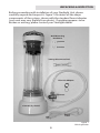
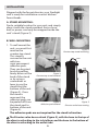
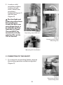
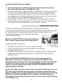
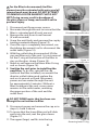
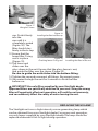
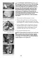
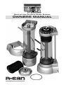
Point-of-Use Drinking Water System
OWNERS MANUAL
E N V I R O N M E N TA L
INC
Ensuring the Safety of Your Water
Point-of-Use Drinking Water System
OWNERS MANUAL
Congratulations on the purchase of your new Sterilight Point-of-Use
Drinking Water System. This unit is designed to operate for years
with minimal maintenance. If you have any questions regarding the
operation of the unit, these instructions, or how to obtain service on the
unit, please contact your local Sterilight dealer, or contact Sterilight at
www.r-can.com.
This symbol is used throughout this manual to notify you of
particularly important information.
STERILIGHT UNIT USE RESTRICTIONS
Your Sterilight Unit is designed to improve the taste and quality
of otherwise potable, optically clear municipal or well water. The
patented Sterilight treatment system also provides an environment that
is inherently hostile to certain microbiological contaminates. Please note
the following use restrictions:
1. Water entering the unit must be free of sediment and loose scale
or rust. If your water does not meet these requirements, it must be
pre-filtered prior to entering the unit.
2. For optimum performance, the unit must be monitored for proper
operation each time it is used. Proper operation is described on
page 6 of this manual.
TABLE OF CONTENTS
Unpacking and Inspection....................... 3
Installation Instructions....................... 4
Operation....................... 6
Replacing the Filter Element....................... 7
Replacing the UV Lamp....................... 9
Trouble Shooting Guide..................... 11
Replaceable Parts List..................... 12
Specifications..................... 12
2
UNPACKING & INSPECTION
Before proceeding with installation of your Sterilight Unit, please
carefully unpack and inspect it. Figure 1 illustrates all the major
components of the system, shown with the standard faucet diverter
(your unit may vary slightly from photo). If anything appears to be
broken or missing, please contact your Sterilight dealer.
Wall Mounting
Hardware
Tubing Disconnect Tool
Diverter Adapter
Diverter
Counter Top Stand
Power
Cord
Figure 1
Unit inspection
3
INSTALLATION
Shipped with the faucet diverter, your Sterilight
unit is ready for installation on most kitchen
faucet heads.
A. STAND MOUNTING:
Find a suitable location for your unit, and simply
place it with the stand provided. Excess hose
and/or power cord may be wrapped inside the
unit’s stand (Figure 2).
B. WALL MOUNTING
1. To wall mount the
unit, you must first
Figure 2
remove the
Counter-top stand mounting
counter-top stand.
This stand is
OUTLET
secured to the unit
with two
semi-permanent
adhesive pads.
INLET
They can be pried
loose by pulling
OUTLET
Figure 3
firmly down on the
Counter-top stand removal
back of the stand
or by using a
screwdriver or
lever to pry the
stand from the
bottom of the unit
(Figure 3). Once
the stand is
OUTLET
removed, the
INLET
adhesive pads can
be peeled off from
Figure 4
Figure 5
Adhesive pad removal
Diverter valve hose routing
the stand and/or
bottom of the unit
(Figure 4).
The adhesive pads are not required for the stand to function.
The Diverter valve hoses attach (Figure 5), with the hose to the top of
the diverter attaching to the inlet elbow, and the hose to the bottom of
the diverter attaching to the outlet tube.
4
2. Locate a solid
mounting surface
(such as a wall
stud). Attach the
mounting
hardware (Figure 7)
and the unit
(Figure 8).
The Sterilight unit
generates ozone from
surrounding air.
Locate the unit in an
area where the air is
breathable and free
from dust or fumes.
The unit MUST be
mounted vertically,
with the filter at the
TOP of the unit.
Figure 6
Separating stand from unit
Figure 8
Hanging unit on Wall
Mounting Pins
Figure 7
Mounting Pin Installation
C. CONNECTING TO THE FAUCET
1. To connect to an existing faucet, remove
the existing aeration nozzle and gasket
(Figure 9).
Figure 9
Removing aeration
nozzle and gasket
5
2. If the diverter supplied with the unit will
not attach directly to your faucet, install the
adapter. When done, or if the adapter is not
needed, connect the Sterilight unit diverter
valve assembly to the faucet (Figure 10).
3. Plug the power supply into an
available outlet.
The outlet MUST always have power
available. Do not plug the unit into an outlet
that can be switched on or off.
Figure 10
Attaching diverter
to Faucet
The unit is now ready for operation.
OPERATION
Prior to drinking water from the unit, flush unit for five minutes.
To operate the unit, simply turn on the cold water faucet and pull the
diverter valve plunger outward (Figure 11). To
bypass the unit, push the diverter valve inward.
You will observe the following when the
Sterilight unit is operating properly:
1. Once flow is established, the UV lamp will
turn on and become fully bright and steady
within the first second of operation.
2. Water enters the unit at the bottom where it
is mixed with ozone, forming a Sterilight of
swirling bubbles and a swooshing sound.
Figure 11
Turn on the faucet by pulling
the diverter valve flow
control knob outward.
The unit will automatically
come on.
3. Any ozone left following the patented
ozone/UV photo-oxidation process is reconverted to oxygen in the
filter element. Water leaving the unit is fully treated and mixed
with air and the reconverted ozone. The air will appear as tiny
bubbles, sometimes giving the water an initial cloudy appearance.
After sitting for a minute or so,
all of the bubbles will rise to the surface and disperse, leaving the
water crystal clear.
4. Because of the trapped air, the water outlet from the unit will
occasionally sputter, particularly at start-up.
6
PLEASE NOTE THE FOLLOWING
1. The Sterilight unit is NOT designed to operate with hot water.
Run only cool tap water through the unit.
2. The ultraviolet lamp in the unit has a useful life of 10,000 on-off cycles
or more. One cycle could be a small cup of water or a large pitcher.
To maximize the life of the lamp, it is best to get a pitcher to store in
the refrigerator for drinking during the day, as opposed to running it
several times to draw individual glasses of water.
3. Depending on the model, your Sterilight ultraviolet lamp may stay
illuminated for approximately 30 seconds after flow through the unit
has ceased. This is normal and is not cause for concern.
REPLACING THE FILTER
The filter element in the Sterilight unit is a high-performance,
multi-layer extruded design. The element has been specifically designed
to complement the patented ozone/UV photo-oxidation process.
Replacement filters can be obtained through
your Sterilight dealer.
The unit MUST NOT be operated without a
filter element except when sanitizing (page 8).
Replace the filter whenever:
Figure 12
Removing Tubing
from fittings
1. The filter has been in service six or more months.
2. 1900 or more liters of water (500 gallons) have been
processed by the unit.
3. The filter shows signs of dirt build-up or deterioration, evidenced by
a decrease in the rate of water flow, or a decrease in the swirling
bubble action.
It is EXTREMELY IMPORTANT that the unit be unplugged. The
Sterilight unit contains a high intensity ultraviolet lamp that can
damage tissues in the eye. The UV wavelengths cannot travel through
the plastic housing. However, removing the filter requires that the
cap be removed, exposing the lamp. DO NOT PROCEED WITHOUT
UNPLUGGING THE UNIT!
The Sterilight unit uses state-of-the-art Speed Fit® fittings. They rely
on a lock ring to hold the tubing in place. To remove tubing from the
fitting, hold the lock ring against the fitting while pulling on the tubing.
While it is possible to do this with your fingers, included with your
Sterilight unit is a tubing disconnect tool to make removing the fittings
easier (Figure 12).
7
For the filter to be removed, the filter
element must be saturated with water and all
internal seals must be wet. DO NOT ATTEMPT
TO REMOVE A FILTER ELEMENT THAT IS NOT
WET. Doing so may result in breakage of
the glass sleeve or lamp, and could result in
personal injury.
1. Disconnect unit from power source.
2. Run water through the unit to insure that the
filter is saturated and all seals are wet.
3. Remove the unit from its wall mount
(if wall mounted)
4. Grasp the unit firmly and unscrew the cap by
turning counterclockwise (Figure 13).
5. Once the cap is completely unscrewed, use
the tubing disconnect tool to disconnect the
outlet tube (Figure 14).
6. With the outlet tube disconnected, lift the
cap and filter out of the unit. It is not unusual
for the O-ring at the bottom of the filter to
stay on the glass sleeve (Figure 15).
7. Reach in and remove the lower filter O-ring
seal as shown (Figure 16).
8. Sanitize the unit prior to installing the
new filter. To do this, reinstall the cap
(without the filter installed), reconnect the
diverter outlet tubing and replace the
unit on its mount or stand. Reconnect
power and run water through the unit
for approximately 5 minutes. Without a
filter cartridge in the unit, some ozone
remains in the outlet water, sanitizing
the upper portion of the unit and the
outlet lines.
Figure 13
Disconnecting outlet tube
Lower O-ring
Figure 14
Disconnecting outlet tube
Figure 15—Unscrewing cap
and removing filter
DO NOT DRINK water that has been run
through the unit without a filter.
9. Disconnect power and remove the cap as in
steps 3, 4 and 5 above.
10. To insure that the lower filter seal will slide
easily into the unit, wet the glass sleeve
(Figure 17).
11. The upper (large) seal fits into the top
8
Figure 16
Removing lower O-ring
Figure 17
Wet glass sleeve
Figure 18
Installing the filter into the cap
cap. Push it firmly
into the
cap until it is
completely seated
(Figure 18). The
filter should stay
firmly in the to cap.
12. Ensure that the
lower filter O-ring
Figure 20
seal is in place
Figure 19
Checking lower O-ring seal Installing the filter in the unit
(Figure 19).
13. The lower seal
slides over the
glass sleeve in the unit. Ensure that the glass sleeve is wet,
and guide the filter over the sleeve (Figure 20).
Be sure to guide the outlet tube into the bottom fitting.
14. Tighten the cap and reconnect all fittings. Reconnect power.
15. Run water through the unit for 5 minutes to flush the filter
before use.
IMPORTANT! Use only filters supplied by your Sterilight dealer.
Approved filters are specifically matched to your unit. Using the wrong
filter will negatively effect unit operation, will void the unit warranty,
and can adversely affect the safety of water leaving the unit.
REPLACING THE UV LAMP
The Sterilight unit uses a high-intensity ozone generating lamp which
can be obtained from your Sterilight dealer. For proper unit operation,
use only lamps supplied by your Sterilight dealer. The lamp should be
replaced whenever it fails to light during operation.
9
Figure 21—Draining the Unit
Figure 22
Removing cover retaining screws
It is EXTREMELY IMPORTANT that the unit
be unplugged before servicing. The Sterilight
Point-of-use unit contains a high intensity
ultraviolet lamp that can damage tissues in
the eye. The UV wavelengths cannot travel
through the plastic housing. However, the
lamp will be exposed during removal and
replacement. In addition, it is possible to
encounter hazardous electrical energy when
removing the protective bottom cover.
DO NOT PROCEED WITHOUT UNPLUGGING
THE UNIT!
1. Disconnect unit from power source.
2. Remove the unit from its wall mounting,
remove the filter, drain the water from the
unit (Figure 21), and lay it down horizontally.
3. Using a Phillips-head screwdriver, remove
the retaining screws on the cover located
at the bottom of the unit (Figure 22) and
carefully slide the cover off of the unit .
Figure 23 (Internal Power Supply)
Removal of Single Socket
lamp Connection
4. Disconnect the lamp wires.
NOTE: Depending on model, your unit may
have an internal or external power supply.
Units with an internal power supply appear
as in Figure 23. Units with an external power
supply appear as in Figure 24.
Figure 24 (External Power Supply)
Figure 25 (External Power Supply)
Loosening lamp retention screw
10
Figure 26 (Internal Power Supply)
Removing lamp
5. Loosen the lamp retention screw (External
Power supply units–Figure 26).
6. Slide the lamp out carefully
(Figures 26 and 27).
7. Insert the new lamp in the sleeve and
reinstall the lamp.
8. Reinstall lamp wiring and the bottom cover.
9. Reinstall the filter as provided in the filter
replacement instructions (see page 7).
10. Reconnect power.
The unit is now ready for operation.
Figure 27 (External Power Supply)
Removing lamp
TROUBLESHOOTING GUIDE
SYMPTOM
POSSIBLE CAUSE
POSSIBLE SOLUTION
Unit leaking at tubing
connection(s) after unit has been
serviced.
Tubing not securely connected
and/or tubing lock ring not
secured over tubing fitting.
Verify that tubing is properly
connected and that the lock ring
is engaged.
Unit leaks around top cap after
filter has been replaced.
O-ring on top is not properly
seated.
Verify O-ring is seated.
Water is flowing from the unit at a
very slow rate.
Filter element plugged.
Diverter screen plugged.
Inlet plugged.
Replace filter.
Remove diverter valve from the
faucet and clean the screen.
Reverse flow to unit temporarily
to remove blockage. This can
be done by temporarily reversing
inlet and outlet fittings.
Lamp does not light when unit is
operated.
No power.
Lamp burned out.
Make sure power is available.
Replace lamp.
No bubbles are visible in the
incoming stream.
Filter is exhausted.
Replace Filter.
After removing unit for service,
no bubbles are visible in unit
when running.
Inlet and oulet tubing has been
reversed, causing reverse flow
through the unit.
Reverse tubing connections.
Unit is mounted above counter
with diverted valve assembly
attached to the sink and partially
drains when not in use.
Diverted valve not fully closing
when water is turned off.
Push diverted valve in when unit
is not in use.
11
REPLACEABLE PARTS LIST
Your Sterilight Point-of-Use treatment system has
very few user-serviceable parts:
Filter Cartridge................... SWM-C1
Filter Cap O-ring................ OR-SWM
Lamp Assembly................. SWM-RL
Quartz Sleeve..................... QS-SWM
PARTS & SERVICE: Contact your Sterilight dealer.
SWM SPECIFICATIONS
Power requirements: SWM1, 115V AC, 20 WATTS
SWM1/2, 220V AC, 20 WATTS
Flow rate: Up to 2 lpm (0.5 gpm)
Minimum inlet pressure: 30 PSIG
Maximum operating pressure: 6.9 bar (100 PSIG)
Filter life: 6 months or 1900 liters (500 gallons)
Lamp life: 10,000+ on/off cycles
Weight: Approximately 2.2 kg. (5 lbs.)
Dimensions: Approximately 150 x 445 mm
(5.9 x 17.5 inches)
Chemical additives: None; (ozone created in unit)
Chemical emissions: None; (ozone reconverted to oxygen
in the filter cartridge element)
E N V I R O N M E N TA L
INC
Ensuring the Safety of Your Water
425 Clair Rd. West
P.O. Box 1719
Guelph, Ontario, Canada N1H 7X4
tel. (519) 763-1032 • Fax (519) 763-5069
1-800-265-7246
email: [email protected] • Internet: www.r-can.com
US Patents: 5540848, 5266215, DS 357058
Other Patents Pending
©2001, R-Can Environmental Inc.
12