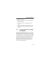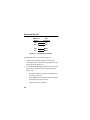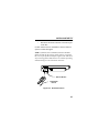
1
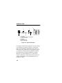
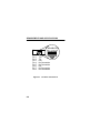
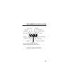
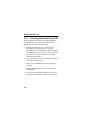
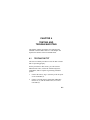
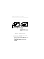
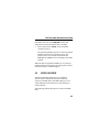
TPT
10BASE-T
TWISTED PAIR TRANSCEIVER
USER’S MANUAL
CABLETRON SYSTEMS, P.O. Box 5005, Rochester, NH 03867-5005
NOTICE
The information presented in this document, including descriptions of hardware,
firmware, and software, is subject to change without notice and should not be
construed as a commitment by Cabletron Systems. Cabletron Systems assumes no
responsibility for any errors that may appear in this manual. The reader should in
all cases contact Cabletron Systems to determine whether changes have been made
affecting the manual.
IN NO EVENT SHALL CABLETRON SYSTEMS BE HELD LIABLE FOR ANY
INCIDENTAL, INDIRECT, SPECIAL, OR CONSEQUENTIAL DAMAGES
WHATSOEVER (INCLUDING , BUT NOT LIMITED TO, LOST PROFITS)
ARISING OUT OF, OR RELATED TO, THIS MANUAL OR THE
INFORMATION CONTAINED IN IT, EVEN IF CABLETRON SYSTEMS HAS
BEEN ADVISED OF, KNEW, OR SHOULD HAVE KNOWN, THE
POSSIBILITY OF SUCH DAMAGES.
The information in this document is proprietary and is not to be copied in any form,
or by any means, without the written consent of Cabletron Systems.
© Copyright January 1992 by
Cabletron Systems Inc.
P.O. Box 5005, Rochester, NH 03867-5005
All Rights Reserved
Printed in the United States of America
Order number: 9030346-02 January 1992
LANVIEW, TPT, TPMIM, MMAC, and LAN-MD are trademarks of Cabletron
Systems Inc.
Velcro is a registered trademark of Velcro Industries, B.V.
i
FCC NOTICE
FCC NOTICE
WARNING: This equipment has been tested and found to comply with the limits
for a Class A digital device, pursuant to Part 15 of FCC Rules. These limits are
designed to provide reasonable protection against harmful interference when the
equipment is operated in a commercial environment. This equipment uses,
generates, and can radiate radio frequency energy and if not installed in accordance
with the operator's manual, may cause harmful interference to radio
communications. Operation of this equipment in a residential area is likely to cause
interference in which case the user will be required at his own expense ot correct the
interference.
If this equipment does cause interference to radio or television, which can be
determined by turning the equipment off and on, the user is encouraged to try to
correct the interference by one or more of the following measures:
•
•
•
•
Re-orient the receiving antenna.
Relocate the transceiver with respect to the antenna.
Move the transceiver away from the receiver.
Plug the Ethernet device into a different outlet so that the device and the
receiver are on different branch circuits.
If necessary, the user should consult the dealer or an experienced radio/ television
technician for additional suggestions. The user may find the following booklet
prepared by the Federal Communication Commission helpful:
“How to Identify and Resolve Radio TV Interference Problems”
This booklet is available from the U.S. Government Printing Office, Washington
D.C. 20402 - Stock No. 004-000-00345-4
ii
CONTENTS
CHAPTER 1 - INTRODUCTION
1.1
1.2
1.3
USING THIS MANUAL...............................1-1
GETTING HELP .........................................1-2
THE TPT 10BASE-T TWISTED PAIR
TRANSCEIVER..........................................1-3
CHAPTER 2 - REQUIREMENTS AND
SPECIFICATIONS
2.1
2.2
NETWORK DESIGN GUIDELINES ...........2-1
OPERATING SPECIFICATIONS ...............2-5
CHAPTER 3 - INSTALLING THE TPT
3.1
3.2
3.3
UNPACKING THE TPT ..............................3-1
MOUNTING THE TPT................................3-2
CONNECTING THE TPT TO THE
NETWORK .................................................3-3
3.3.1 Setting the SQE Switch .................3-3
3.3.2 Connecting to an Ethernet Dev .....3-4
iii
Contents
3.3.3
3.3.4
Connecting the TPT to a Twisted
Pair Segment ................................ 3-5
Providing Strain Relief................... 3-8
CHAPTER 4 - TESTING AND TROUBLESHOOTING
4.1
4.2
iv
INSTALLATION CHECK-OUT ................... 4-1
USING LANVIEW ...................................... 4-3
CHAPTER 1
INTRODUCTION
Welcome to Cabletron Systems’ TPT™ 10BASE-T
Twisted Pair Transceiver User’s Manual. We have
designed this manual as a simple installation and reference
guide to the TPT. The TPT provides 10BASE-T compliant
twisted pair connectivity to your Ethernet network.You
should read this manual thoroughly to fully understand the
TPT and its capabilities.
1.1
USING THIS MANUAL
Chapter 1, Introduction, is an overview of the TPT
10BASE-T Twisted Pair Transceiver. This chapter shows
how to use the TPT in an Ethernet network and explains
the TPT’s features.
Chapter 2, Requirements and Specifications, contains
network design guidelines for connecting the TPT to the
network. The chapter also contains the specifications for
the TPT.
1-1
INTRODUCTION
Chapter 3, Installing the TPT, contains steps for
unpacking the TPT, setting the SQE switch, connecting the
transceiver to the network, and connecting the transceiver
to an Ethernet device.
Chapter 4, Testing and Troubleshooting, contains
procedures for verifying that the TPT is operational. It also
describes the LANVIEW™ LEDs, and how you can use
them to troubleshoot network problems.
Before you install the TPT, you should have a general
working knowledge of Ethernet or IEEE 802.3 type data
communications networks and their physical layer
components.
1.2
GETTING HELP
If you need additional support concerning Cabletron
Systems TPT, or if you have comments, questions, or
suggestions concerning this manual, feel free to contact
Cabletron Systems’ Technical Support at:
Cabletron Systems
35 Industrial Way
P.O. Box 5005
Rochester, NH 03867-5005
Phone: (603) 332-9400
1-2
INTRODUCTION
1.3
THE TPT 10BASE-T TWISTED PAIR
TRANSCEIVER
Connections
The TPT (Fig. 1-1) is designed to connect two Ethernet
devices. Because the TPT is small, it can connect to
Ethernet devices directly, or you can connect it by means
of an AUI cable. The TPT fully conforms to IEEE 802.3
10BASE-T specifications and guarantees the flexibility to
connect to networks using IEEE 802.3 or Ethernet Version
1 or 2 equipment.
TOP VIEW
RJ-45 Port
SQE Switch
AUI Port
Enable
TPT
LANVIEW
LEDs
Disable
SQE
92 SERIES
802.3 10BASE-T TRANSCEIVER
WITH LANVIEW
LNK
COL
RCV
XMT
SQE
SN
PWR
b
SIDE VIEW
SIDE VIEW
FRONT VIEW
Figure 1-1
TPT
1-3
INTRODUCTION
The TPT 10BASE-T Twisted Pair Transceiver lets you use
existing twisted pair wiring as part of an Ethernet network.
Distance and Cable Type
The TPT supports an unshielded twisted pair (UTP)
segment, up to 100 meters (328 feet) of 24 AWG UTP with
an impedance of 85-110 ohms.
Signal Quality Error (SQE) Test
The TPT has a Signal Quality Error (SQE) Test Switch
that lets you turn on or off the SQE (“heartbeat”) test
function. With SQE Test turned on, the transceiver
generates a test signal after each packet transmission that
checks the collision circuit and path between the TPT and
the device attached to the transceiver’s AUI port.
NOTE: You must disable the SQE test if you attach the
TPT to Version 1 equipment or to a repeater. Version 1
equipment and repeaters interpret the SQE test pulse as a
collision, which significantly slows the network response
time.
Polarity Detection and Correction
The TPT incorporates a Polarity Detection and Correction
feature. This feature lets the TPT pass data to and from the
1-4
INTRODUCTION
host, regardless of the polarity of the twisted pair
segment’s receive link. If polarity is reversed, the
LANVIEW LNK (Link) LED will flash.
NOTE: If you have a polarity mismatch, you should
remove the segment from the TPT and correct the problem.
This will make the segment compatible with a device that
does not have the Polarity Detection and Correction
feature.
LANVIEW LEDs
The TPT incorporates Cabletron Systems’ LANVIEW
diagnostic and monitoring system. LANVIEW gives a
visual indication of problems such as power failures,
collisions, and cable faults. LANVIEW can alert you to a
problem condition, and indicate the nature of the problem,
which streamlines troubleshooting.
Application
An Ethernet device, such as a workstation (1, Fig. 1-2)
connects to the TPT Transceiver (2) through the TPT AUI
port. An RJ-45 jack on the twisted pair segment (3)
connects to the RJ-45 port on the TPT Transceiver. The
twisted pair segment connected to the TPT can be attached
to 10BASE-T compliant products.
1-5
INTRODUCTION
4
2
1
3
1.
2.
3.
4.
5.
6.
6
5
Workstation
TPT (directly attached to Workstation)
Twisted Pair Jumper
Wall Plate
Twisted Pair Cable
MMAC with TPMIM
Figure 1-2
Typical TPT Setup
For example, the twisted pair segment (3) can be a jumper
to a wall plate (4). From the wall plate, a twisted pair
cable (5) in the building’s distribution wiring runs to a
distribution closet. In the closet, the twisted pair segment
is connected to Cabletron Systems 10BASE-T Twisted
Pair Media Interface Module (TPMIM™) in a Multi
Media Access Center (MMAC™) (6). In this configuration, a 10BASE-T, twisted pair network is set up over
existing, unused phone wires, eliminating the cost of
pulling new cables.
1-6
CHAPTER 2
REQUIREMENTS AND
SPECIFICATIONS
This chapter describes the network requirements for
connecting the TPT 10BASE-T Twisted Pair Transceiver
to a twisted pair segment and an Ethernet device. The
chapter also lists specifications and power requirements.
Review all specifications, guidelines, and requirements in
this chapter before you install the TPT. You must meet all
these conditions to ensure satisfactory performance of
your network.
2.1
NETWORK DESIGN GUIDELINES
You must meet the following IEEE 802.3 10BASE-T
Twisted Pair requirements when connecting devices with
the TPT.
•
Length - The IEEE 802.3 10BASE-T standard
requires that 10BASE-T transceivers transmit over a
2-1
REQUIREMENTS AND SPECIFICATIONS
100 meter (328 ft.) link using 22-26 AWG unshielded
twisted pair wire.
As a general rule, links up to 150 meters (492 ft.) for
unshielded twisted pair and 200 meters (656 ft.) for
shielded twisted pair are possible. For each connector or
patch panel inthe link, subtract 12 meters (39 ft.) from the
150 meter limit.This allows for links of up to 126 meters
(413 ft.) using standard 24 AWG UTP wire and two patch
panels within the link. Higher quality, low attenuation
cables may be required for links of greater than 126
meters. Due to cable delay, themaximum link length is
always limited to about 200 meters,regardless of the cable
type.
•
Insertion Loss - The maximum insertion loss allowed
for a 10BASE-T link is 11.5 dB at all frequencies
between 5.0 and 10.0 MHz. This includes the
attenuation of the cables, connectors, patch panels, and
reflection losses due to impedance mismatches in the
link segment.
•
Impedance - Typical unshielded twisted pair cable
impedance is 85 to 110 ohms. Shielded cables, such
as Type 1 cable, can also be used. Type 1 cable
impedance is typically 150 ohms. The higher
impedance increases the signal reflection caused by
2-2
REQUIREMENTS AND SPECIFICATIONS
the cable. Since the cable is shielded, signal reflection
has little effect on the received signal’s quality, due to
the lack of crosstalk between the shielded cable pairs.
Cabletron Systems’ 10BASE-T Twisted Pair products
work on shielded twisted pair cable with 75 to 165
ohms impedance.
•
Jitter - Intersymbol interference and reflections can
cause jitter in the bit cell timing, which results in data
errors. A 10BASE-T link must not generate more than
5.0 ns of jitter. If your cable meets the impedance
requirements for a 10BASE-T link, jitter should not be
a concern.
•
Delay - The maximum propagation delay of a
10BASE-T link segment must not exceed 1000 ns.
This 1000 ns maximum delay limits the maximum link
segment length to 200 meters.
•
Crosstalk - Crosstalk is caused by signal coupling
between the different cable pairs contained within a
multi-pair cable bundle. 10BASE-T transceivers are
designed so that you do not need to be concerned about
cable crosstalk, provided the cable meets all other
requirements.
•
Noise - Noise is caused by either crosstalk or
externally induced impulses. External noise can cause
2-3
REQUIREMENTS AND SPECIFICATIONS
data errors if the impulses occur at very specific times
during data transmission. Generally, you do not need
to be concerned about noise. If you suspect noise
related data errors, either reroute the cable or eliminate
the source of the impulse noise.
•
2-4
Temperature - Most multi-pair PVC 24 AWG
telephone cables typically have an attenuation of
approximately 8 to 10 dB/100 m at 20° C (68°F). The
attenuation of PVC insulated cable varies significantly
with temperature. At temperatures greater than 40° C
(104°F), we strongly recommend that you use plenum
rated cables to ensure that cable attenuation remains
within specification.
REQUIREMENTS AND SPECIFICATIONS
2.2
OPERATING SPECIFICATIONS
This section contains the specifications, power supply
requirements, and environmental guidelines for the TPT.
Cabletron Systems reserves the right to change these
specifications at any time without notice.
The TPT is designed and manufactured in accordance with
the IEEE 802.3 10BASE-T standard.
INTERFACE CONNECTIONS
Figure 2-1 shows the pin connections for the
RJ-45 receptacle on the TPT. Figure 2-2 shows the pin
configuration of the AUI connecter.
2-5
REQUIREMENTS AND SPECIFICATIONS
12345678
Pin 1
Pin 2
Pin 3
Pin 4
Pin 5
Pin 6
Pin 7
Pin 8
TX+
TXRX+
No Connection
No Connection
RXNo Connection
No Connection
Figure 2-1
2-6
RJ-45 Pin Connections
REQUIREMENTS AND SPECIFICATIONS
4 Logic Ref
5 Receive +
3 Transmit +
6 Power Return
2 Collision +
7 No Connection
1 Logic Ref
8 Shield
9 Collision -
15 No Connection
10 Transmit -
14 Shield
11 Shield
13 Power (+12VDC in)
12 Receive -
Type: 15 Position D Type Receptacle Pin
Connector Shell: Connected to TPT enclosure
Figure 2-2
AUI Pin Connections
2-7
REQUIREMENTS AND SPECIFICATIONS
POWER SUPPLY
Parameter
Typical
Value
Worst
Case
Input Voltage:
12 V
9.5 to 15 V
Total Current
Draw:
170 mA
210 mA max.
ENVIRONMENTAL
Non-operating
Temperature:
-30° to +80° C
Operating
Temperature:
-5° to 60° C
Operation
Humidity:
5 to 95%
2-8
noncondensing
REQUIREMENTS AND SPECIFICATIONS
Electromagnetic
Susceptibility:
Will operate properly in the
following externally applied fields:
10 kHZ to 30 MHz @ 2 V/m
30 MHz to 1000 MHz @ 5 V/m
Electromagnetic
Radiation:
Meets FCC part 15, Class A Limits.
SAFETY
Designed in accordance with UL478, UL910,
NEC725-2(b), CSA, IEC, TUV, VDE Class A. Meets FCC
part 15, Class A limits.
WARNING: It is the responsibility of the person who sells
the system of which the TPT will be a part, to ensure that
the total system meets allowed limits of conducted and
radiated emissions.
2-9
REQUIREMENTS AND SPECIFICATIONS
PHYSICAL
Dimensions:
9.9 x 4.1 x 2.0 cm
3.7 x 1.6 x .8 in
Weight:
68 gm
.15 lb
2-10
CHAPTER 3
INSTALLING THE TPT
This chapter outlines the procedure for connecting the
TPT to your network. Be sure that all specifications and
requirements listed in Chapter 2, Requirements and
Specifications, are met before you install the TPT.
3.1
UNPACKING THE TPT
To unpack the transceiver:
1.
Remove the accessory bag from the shipping box, and
make sure it contains the following:
•
•
•
one set of Velcro® mounts
two 6 inch cable ties
two mounting bases for the cable ties
2.
Remove the TPT from the shipping box.
3.
Remove the TPT from the packing material and the
protective plastic bag. Set the transceiver aside.
3-1
INSTALLING THE TPT
3.2
MOUNTING THE TPT
Using the contents of the accessory package, you can
mount the TPT on a surface close to the workstation, or on
the workstation itself. The surface you choose should meet
the following requirements:
•
Allows the twisted pair segment to be easily connected
to the transceiver
•
Allows an AUI cable to be easily connected to the
transceiver
•
Has a smooth, dirt free surface that will accept the
adhesive bonds
Mount the TPT as follows:
1.
Separate the two Velcro mounts.
2.
Peel off the paper that covers the adhesive backing of
one Velcro mount.
3.
Carefully position the Velcro on the back of the TPT
and press firmly.
4.
Similarly, place the other half of Velcro on the surface
on which you want to mount the TPT.
3-2
INSTALLING THE TPT
5.
Mount the transceiver by attaching the Velcro-backed
TPT to the Velcro mount.
3.3
CONNECTING THE TPT TO THE
NETWORK
After you are sure that you have met all the requirements
listed in Chapter 2, complete the installation instructions
listed in this section.
3.3.1
Setting the SQE Switch
The SQE Test switch lets you enable or disable the SQE
test function. The SQE switch is the two-position slide
switch on top of the TPT.
CAUTION: You must disable the SQE test function if you
are connecting the transceiver to a repeater or to an
Ethernet Version 1 device. In addition, some Version 2
equipment does not support the SQE Test function. The
SQE test function is enabled when the transceiver is
shipped. Devices that do not support the SQE Test function
will interpret the SQE test pulse as a collision, which will
cause poor network performance.
3-3
INSTALLING THE TPT
To set the SQE switch:
•
To turn the SQE test function off, slide the SQE switch
toward the RJ-45 port. This should align the switch
with the off position (°).
•
To turn on the SQE test function, slide the SQE Switch
toward the AUI port. This aligns the switch with the on
position (•), as indicated on the front of the TPT.
3.3.2
Connecting the TPT to an
Ethernet Device
The TPT connects directly to an Ethernet device through
an AUI connection. You can either connect the TPT
directly to the device or use an AUI cable. If there is a slide
lock on the female connector, slide it to secure the
connector to the lock posts on the TPT’s AUI port.
Once connected, the LANVIEW PWR LED should be lit,
indicating that the transceiver is receiving power from the
device. If the SQE Test function is turned on, then the SQE
LED should also be lit.
3-4
INSTALLING THE TPT
If the PWR LED is not lit:
1.
Make sure that the power is turned on for the device
attached to the TPT.
2.
Disconnect the device to which the transceiver is
attached.
3.
Check the AUI connections for proper pinouts. The
pinouts for the transceiver connection are listed in
Chapter 2.
3.3.3
Connecting the TPT to a Twisted
Pair Segment
The physical communication link consists of two pairs of
wires; the first pair is the Transmit Pair (TX+, TX-), the
second pair is the Receive Pair (RX+, RX-). The Transmit
Pair of the TPT transceiver connects with the Receive Pair
of an Ethernet device, maintaining polarity. For example,
the positive transmit lead (TX+) of an Ethernet device
goes to the positive receive lead (RX+) of the TPT. The
Receive Pair of the Ethernet device connects to the
Transmit Pair of the TPT. This provides the necessary
Crossover or Null Modem Effect.
3-5
INSTALLING THE TPT
10BASE-T
Device
TPT
Tranceiver
RX+
RX-
TX+
TX-
TX+
TX-
RX+
RX+
Figure 3-1
Twisted Pair Connection
To connect the TPT to your network (Fig. 3-3)
1.
Connect the twisted pair segment to the TPT by
inserting the RJ-45 connector on the segment into the
RJ-45 port on the transceiver.
2.
Verify that the LNK LED on the transceiver is lit. If the
LED is not lit, perform each of the following steps
until it is lit:
3-6
•
Disconnect the RJ-45 connector from the RJ-45
port of the transceiver.
•
Verify that the RJ-45 connector on the twisted pair
segment has the proper pin outs.
•
Check the cable for continuity.
INSTALLING THE TPT
•
Reconnect the RJ-45 connector to the RJ-45 port
of the TPT.
If a link still has not been established, contact Cabletron
Systems’ Technical Support.
NOTE: If link has been established, but the LNK LED
flashes on and off, the polarity of the cable is reversed in
the receive pair of the twisted pair segment. The TPT has a
self correcting feature that allows it to continue operating
without having to rewire the RJ-45 connector.
TPT RJ-45 Port
To Network
Device
Figure 3-2
RJ-45 Connection
3-7
INSTALLING THE TPT
3.3.4
Providing Strain Relief for the TPT
We recommend that you support the cabling attached to
the TPT-4 to relieve the stress on the connections. To
support the UTP segment and AUI cable:
1.
Mark the location where you want to place the
mounting bases for the cable ties. To provide
maximum strain relief to the cables, support should be
provided about 4" from the TPT-4’s RJ-45 port, and if
necessary, near the end of the built-in AUI cable
extending from the TPT-4.
2.
Peel off the paper that covers the adhesive backing of
each plastic mounting base.
3.
Firmly press each mounting base into the marked
positions.
4.
Thread a cable tie through one set of slots on each
mounting base.
5.
Once you have attached all cabling to the TPT-4, as
described in the preceding sections, tie off the cables.
3-8
CHAPTER 4
TESTING AND
TROUBLESHOOTING
This chapter contains procedures for testing the TPT
10BASE-T Twisted Pair Transceiver. This chapter also
explains the function of the LANVIEW LEDs.
4.1
TESTING THE TPT
This section contains procedures to test the TPT to ensure
that it is operating properly.
For the procedures in this section, you will need two
Ethernet node testers, such as the Cabletron Systems’
LAN-MD™, that are capable of generating valid data
packets.
1.
Connect the TPT (2, Fig. 4-1) directly to the AUI port
on one LAN-MD (2).
2.
Connect a second properly functioning 10BASE-T
transceiver (4), such as another TPT, to a second
LAN-MD (5).
4-1
TESTING AND TROUBLESHOOTING
3.
Attach a crossed-over twisted pair segment (3)
between the two transceivers.
1
5
2
3
Figure 4-1
4.
4-2
4
1. LAN-MD
2.TPT (directly attached to LAN-MD)
3.Twisted Pair Segment
4.TPT (directly attached to LAN-MD)
5.LAN-MD
Installation Checkout
Select and run test 6, SERVER, on the LAN-MD
connected in step 1. Verify that:
•
the status on the LAN-MD is 000 if SQE is on or
001 if SQE is off
•
a PASS TEST STATUS LED is lit on the
LAN-MD
TESTING AND TROUBLESHOOTING
LAN-MD 1 now acts as the SERVER unit and will
echo packets when used with the other LAN-MD.
5.
Select and run test 4, NODE, on the LAN-MD
connected in step 2.
Verify that the NODE test passes. At least 100 packets
should be sent and received with no errors. The
packets will be received and sent back from the
SERVER LAN-MD that was left running on the other
segment.
When the TPT has passed the NODE test, it is ready for
normal operation. If any failures are noted, please contact
Cabletron Systems’ Technical Support.
4.2
USING LANVIEW
The TPT Twisted Pair Transceiver uses Cabletron
Systems’ built-in diagnostic and status monitoring
system, LANVIEW. The LANVIEW LEDs give you a
visual indication of network activity and can help you
isolate problems.
The following explains the purpose of each LANVIEW
LED.
4-3
TESTING AND TROUBLESHOOTING
Power (PWR) LED
When lit, this green LED indicates that the transceiver is
receiving power though its AUI connection. If the PWR
LED is not lit, power is not being received from the
device, or the DC-to-DC converter in the transceiver has
failed.
SQE
EIVER
LNK
COL
RCV
XMT
SQE
SN
Figure 4-2
PWR
LANVIEW
LEDs
LANVIEW LEDs
Signal Quality Error (SQE or “Heartbeat”) Test
Function (SQE) LED
When lit, this yellow LED indicates that the transceiver’s
SQE test function is on.
4-4
TESTING AND TROUBLESHOOTING
The SQE test is used to ensure that the collision presence
circuit and the path between the Ethernet device and the
transceiver are operational. This test is generated by the
transceiver after a data packet has been transmitted
through the transceiver.
Transmit (XMT) LED
This green LED flashes while a data packet is being placed
onto the network by the device connected to the
transceiver. The LED flash is pulse-stretched for viewing
effect. The XMT LED stays off if the device is active, but
not transmitting data onto the network.
Receive (RCV) LED
This yellow LED flashes when the transceiver receives
data from the network. If the transceiver is attached to a
device such as a repeater, the RCV LED flashes when data
passes through the transceiver, even though that data is not
addressed to the repeater itself. The LED flash is
pulse-stretched for viewing effect.
Collision Present (COL) LED
This red LED flashes when the transceiver detects a
collision condition or a jabber packet on the network. The
flash frequency may increase as network activity increases
since more collisions are likely to occur. The LED flash is
pulse-stretched for viewing effect.
4-5
TESTING AND TROUBLESHOOTING
Media Link Good (LNK) LED
When lit, this green LED indicates that a link exists
between the transceiver and the 10BASE-T device at the
other end of the twisted pair segment. The LNK LED
remains lit as long as the link is maintained.
A regular continuous flash means that the receive pair on
the twisted pair segment is wired with the polarity
reversed. The TPT will operate normally due to the
Polarity Detection and Correction feature.
If no data has been sent for 20 ms, a positive link test pulse
of 100 ns is sent onto the transmit link of the twisted pair
cable. The TPT receives the link pulse and checks for the
correct rate, polarity and pulse shape. If no pulses are
received or the pulses are not correct, the transceiver
enters the Link Fail State and the LED will not be lit. The
TPT will not receive or transmit data until it receives a
correct link test pulse or a valid packet.
4-6