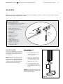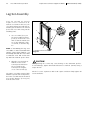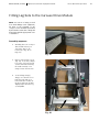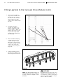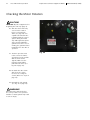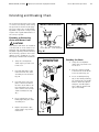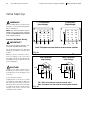
1
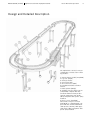
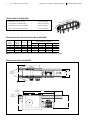
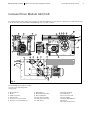
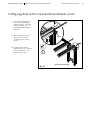
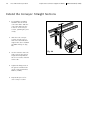
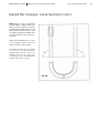
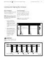
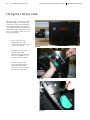
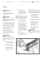
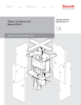
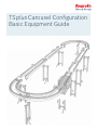
TSplus Carousel Configuration
Basic Equipment Guide
R980 500 388 (6.2010)
TSplus Carousel Basic Equipment Guide
Bosch Rexroth Corporation
2
Table of Contents
Important Safety Infomation....................................... 3
Introduction................................................................ 4
Leveling and aligning.......................................... 22
Fitting the flat-top GT2 chain............................. 23
Checking the Motor Rotation............................. 27
Extending and breaking the chain...................... 28
Application and Function............................................ 5
Design and Detailed Description................................ 6
Technical Data...................................................... 7
Carousel Drive Module......................................... 8
TSplus Conveyor Chain Section Carousel.......... 10
Connection Links............................................... 12
Cross Links........................................................ 12
Chain.................................................................. 13
Foundation bracket/Foundation anchor kit........ 13
Initial Start-up........................................................... 29
Maintenance............................................................. 30
Repair....................................................................... 31
Replacing the guide profile................................ 31
Replacing the sprockets..................................... 32
Replacing the motor........................................... 33
Assembly................................................................... 14
Leg Set Assembly............................................... 14
Fitting leg sets to the Carousel drive module.... 16
Extending the conveyor section......................... 19
Fitting the cross links......................................... 21
Module Warranty
Liability
BOSCH REXROTH CORPORATION warrants to the original
purchaser the modules manufactured by us to be free from
defects in materials and workmanship under normal use
and service. Our obligation under this warranty shall be
limited to the repair or exchange of any part or parts which
may thus prove defective under normal use and service
within one (1) year from date of installation by the original
purchaser. THIS WARRANTY IS EXPRESSLY IN LIEU OF ALL
OTHER WARRANTIES EXPRESSED OR IMPLIED, INCLUDING THE WARRANTY OF MERCHANTABILITY OR FITNESS
FOR USE, AND WE NEITHER MAKE NOR AUTHORIZE ANY
OTHER PERSON TO MAKE FOR US, ANY WARRANTY IN
CONNECTION WITH THE SALE.
In no event can the manufacturer accept warranty claims
or liability claims for damages resulting from improper
use or misuse of the equipment or as a result of changes
made to the equipment other than those authorized by
the manufacturer. The manufacturer will accept no claim
in which non-original spare parts have been used.
This warranty shall not apply to the modules or any part
thereof that has been subject to accident, negligence,
alteration, disassembly, abuse, or misuse after delivery
by us. The term “Original Purchaser”, as used in this warranty, shall be deemed to mean the customer to whom
the modules were originally sold.
Our obligation under this warranty is limited to the modules only, and excludes wear items, such as belts, etc., and
we may not be responsible for system concept, design,
engineering, or function beyond this.
Environmental Protection
Always dispose of worn, damaged or obsolete parts in a responsible manner. Some components, such as gearboxes,
contain lubricating oil which can pollute the environment.
It is the user’s responsibility to dispose of all hazardous
material within the components following all local, state
and federal guidelines.
All rights are held by ROBERT BOSCH GMBH and BOSCH
REXROTH CORPORATION, also regarding patent claims.
We retain all powers of disposition, such as for copying
and/or for passing-on to third parties. We reserve the
right to make technical changes at any time without
notice. Errors and omissions excepted.
© 2010
Bosch Rexroth Corporation
3
Bosch Rexroth Corporation
TSplus Carousel Basic Equipment Guide
R980 500 388 (6.2010)
Important Safety Information!
IMPORTANT: This manual must
be reviewed with all equipment
operators as part of your operator
training program!
SAFETY FIRST!
Important safety information is contained
throughout this manual to alert you to
potentially dangerous situations and help
prevent accidental injury and property
damage.
The safety warning symbol above has been
included to warn you of hazards that can
hurt or kill you and others, and/or cause
serious damage to the equipment and
other property. In addition, the following
safety alert words are used:
DANGER!
Means that you or others will be seriously
or fatally injured if instructions are not
followed.
WARNING!
Means that you or others may be seriously
or fatally injured if instructions are not
followed.
CAUTION!
Means that you or others may be injured
if instructions are not followed.
Material Hazards:
Some components, such as gearboxes,
contain lubricants or other materials that
can represent a potential health hazard if
handled, stored, or disposed of improperly.
Please contact Bosch for copies of the
Material Safety Data Sheets (MSDS) for the
lubricating oil used in gearboxes and other
potentially hazardous materials.
Review All Safety Information:
Please review the safety information
included on this page and throughout this
manual with all installers, operators, and
maintenance personnel of this equipment.
SAVE THESE INSTRUCTIONS
WARNING!
Please read all assembly, and maintenance instructions carefully before
beginning set-up of the components
in this document. Where appropriate, warning symbols have been included in this publication to alert you
of potential or impending danger.
• Be sure to read and observe all safety
warnings in this document as well
as those attached to the individual
modules. Failure to do so could result
in potential risks to your health and
safety as well as those around you.
• Covers and guards have been designed to eliminate pinch points
and exposure to moving chains
and gears. DO NOT operate the
conveyor or any of the other components in the system with the guards
removed. Serious injury may result!
• All set-up maintenance and repair
work should be performed only by
properly trained, qualified personnel. All operators must be properly
trained in the use of this equipment.
• A qualified electrician must make
all electrical connections when wiring the components installed in the
TSplus system. Be sure to follow all
local, state and federal regulations
when installing electrical devices
of any type. The customer assumes
responsibility for the control system,
and must provide an EMERGENCYOFF SWITCH or switches for all
workstation operators to meet all applicable industry and OSHA requirements. In general, emergency-off
switches must be present at easily accessible locations for all operators of
the installed TSplus conveyor system.
• All power supplies must be LOCKED
OUT before beginning maintenance
or repair work of any type on the
conveyor system. Proper LOCK
OUT procedures include the identification of the locked out power
supply with a tag to prevent the
accidental restoration of power.
• TSplus pneumatic components are
designed to operate in a range of
4–6 Bar (58–87 psi). It is the users
responsibility to install a filtered,
regulated air supply to limit the
pressure to that recommended by
the manufacturer. Before beginning
any maintenance or repair, bleed off
the pressure lines to all components
to prevent unexpected or accidental
movement of a system component
which could result in personal injury.
• TSplus drives, returns and conveyor
sections and components are designed to transport Bosch Rexroth
WT2, WT2/A, WT2/A-H workpiece
pallets. Proper usage is defined as
the transport and positioning of parts
and assemblies via the workpiece
pallet and fixture during the assembly
process. In no instances should the
pallet payload, the downward force
applied to the pallet, or the total load
carrying capacity of the entire system
be exceeded. Exceeding published
specifications will result in premature
wear or system failure and may cause
damage to the motor, gearbox, roller
chain, seals and other components.
• CAUTION! Do not operate or work
near mechanical equipment when
wearing loose clothing. Moving
components such as roller chain,
drive belts, drive shafts and pallets
can snag long belts, scarves, ties
and other loose fitting garments,
pull the worker into the equipment and cause serious, or in extreme cases, life threatening injury.
• CAUTION! Operators having long
hair must wear appropriate head
protection (hair nets, hats, and hair
caps) to minimize the risk associated
with working near moving machinery.
Hanging hair can get caught in moving
components such as flat-top chain,
drive belts, drive shafts and pallets,
pull the worker into the equipment
and cause serious, or in extreme
cases, life threatening injury.
WARNING!
Employees must be instructed in safety requirements. Refer to Rexroth document
3842527147 (02.2008), “Instructing Employees on Safety” for an overview of the
dangers, instructions and references to regulations and standards for employees who
operate, maintain, repair or who work on or near Rexroth conveyor transport systems.
A pdf of this multi-language document can be downloaded at: BoschRexroth-us.com/
BRLCatalogs by clicking on “Manuals and Product Updates”
R980 500 388 (6.2010)
TSplus Carousel Basic Equipment Guide
Introduction
Like all Bosch Rexroth flexible assembly systems, TSplus is constructed solely from standardized modules
that are precisely matched to each
other. One important benefit of this
modular design is that you can interlink manual and automatic work stations freely, making TSplus suitable
for virtually any assembly task. Another is that you can easily expand a
TSplus installation: Use TSplus alone
as a closed system, or as a sub-installation in a higher-order materialshandling, manufacturing or assembly
system.
•
•
About this manual
The manual is divided into the
following sections to make it
easier to use:
•
Application and Function
Gives general information about
the TSplus conveyor.
Modules for pallet control are also
required and vary according to the
configuration of the system. These
modules are described in separate
manuals and include the following
•
Technical Data
Provides the most important
technical specifications.
•
Design and Detailed Description
Supplies an overview of the
modules that make up the basic
TSplus conveyor. This section
will familiarize you with the conveyor’s individual components.
•
Assembly
Lists step-by-step instructions
for setting up the conveyor.
•
Initial Start-up
Describes the final procedures
for get-ting the conveyor up and
running.
•
Maintenance
Provides information on preventive maintenance.
Repair
Gives step-by-step procedures
for re-placing any parts subjected to wear. This manual describes the basic equipment for
a TSplus flat-top chain conveyor
arranged in oval configuration:
• Carousel drive
• Chain sections (straight and curved)
• Leg sets
• Cross links
• Foundation brackets
• Chain
• Cushioned and Standard
Stop Gates, Rockers
• Proximity Switch Mounting
Kits
• Accumulation Control Kits
• Code Programmers, Code
Memory Blocks, Code
Readers
• Transverse Conveyors
• Lift-Transverse Units
• Lift-Position Units
• Lift-Rotate Units
Contact Rexroth for information on
this or any other module for flexible assembly.
Bosch Rexroth Corporation
4
5
Bosch Rexroth Corporation
TSplus Carousel Basic Equipment Guide
Application and Function
The flat-top chain version of the
Bosch Rexroth TSplus conveyor uses
dual strands of sideflexing flat-top
chain as its transport medium. The
low coefficient of friction with the
workpiece pallets allows pallets to
be stopped on the conveyor while
the chain continies to move beneath
them. It is thus possible to queue
workpiece pallets as work processes
are performed either manually or automatically.
The dual chain (open center) conveyor design provides access to the
fixtured workpiece from all sides.
The chains themselves are tracked
along the top chain-guide profiles
and are driven at constant speed by
means of drive sprockets.
The carousel drive system is designed for a maximum supported
load weight 175 kg to 815 kg.
Important Information
The carousel configuration is economical because it minimizes the
number of drives, transfer modules,
and chain required. It does not use
a return unit. It consists of four 90°
or two 180° curved sections and an
appropriate number of straight sections. Not only is this configuration
easy to set up, but controls complexity is kept to a minimum because of
reduced I/O requirements. The carousel drive powers the side flexing
flat-top chain through the carousel
configuration.
For maximum efficiency, the drive
unit should be placed at the "downstream" end of the longest straight
section. Ordering parameters allow
you to specify the motor voltage and
frequency, conveyor speed, and drive
width. The gear reducer and motor
are located in the mid-mounted position.
Leg sets are not included and are ordered separately based on conveyor
transport heights.
R980 500 388 (6.2010)
R980 500 388 (6.2010)
TSplus Carousel Basic Equipment Guide
Bosch Rexroth Corporation
6
Design and Detailed Description
The TSplus basic carousel conveyor
configuration consists of the following modules:
10
9
1. Carousel Drive module (AS2/CAR)
2. Leg Sets (SZ2/E)
3. Conveyor Profile
4. Connection links
5. Cross Connector (QV2)
6. Foundation brackets and floor
anchors
7. Flat-top chain (GT2/C)
8. Straight conveyor chain sections
(ST2/C-100) complete with two
anodized aluminum chain profiles
(SP2/C), with upper slide profile
(GP2) and plastic slide profile (FP2)
installed.
9. Drive Leg Set (SZ2/CAR)
10. Curved conveyor sections 4
(KU2/O-90) or 2 (KU2/O-180) complete with two anodized aluminum
chain profiles (SP21C), with upper
slide profile (GP2) and plastic slide
profile (FP2) installed.
7
Bosch Rexroth Corporation
TSplus Carousel Basic Equipment Guide
R980 500 388 (6.2010)
Technical Data for AS2/CAR
Nominal conveyor speed
=
See Below Table
Permissible loading weight = 175 kg to 815 kg
Maximum conveyor unit length
= 30.5 m (100 ft.)
Motor electrical specifications = See Below Table
eters
0.5 m
Max.
=3
ength
L
Electrical data for Carousel Drives Units AS2/CAR
Nom.
M/min
Actual
Speed
RPM
HP
6
9
12
18
5.1
9.4
11.8
18.8
1140
1725
1725
1725
1
1.5
1.5
2
Full Load Amps @ 60 Hz
208/60
n/a
n/a
n/a
n/a
230/60
4.0
4.4
4.4
6.0
460/60
2.0
2.2
2.2
3.0
575/60
1.7
1.75
1.75
1.85
NOTE: Electrical Data for reference only. Refer to motor name plate for actual amperage ratings.
Guards
removed
for clarity
B + 243
B - 75
B + 15
Dimensional data for AS2/CAR
1250
Transport
height
1063
600
444
386
Connection
link
(included)
R980 500 388 (6.2010)
TSplus Carousel Basic Equipment Guide
8
Bosch Rexroth Corporation
Carousel Drive Module AS2/CAR
The TSplus flat-top chain (FTC) carousel drive module AS2/CAR (Fig. 1) is delivered completely assembled and ready
to be mounted to ST2/C-100 and KU2/O-90/180 conveyor chain sections.
6
13
13
19
14
12
8
9
11 17
10
15
3
18
4
8
7
12
1
2
12
13
8
4
3
5
16
15
18
13
8
1
2
Fig. 1
The AS2/CAR carousel drive module
consists of the following main
components:
1.
2.
3.
4.
5.
6.
Gear Reducer
Motor
Chain Tensioner
Drive Chain
Conveyor Section In-Feed
Conveyor Section Out-Feed
7. Idling Wheel
8. Drive Chain Sprocket
9. Drive Shaft FTC
10. Idler Sprocket FTC
11. Drive Sprocket FTC
12. Side Cover
13.
14.
15.
16.
17.
18.
19.
Flange Bearing
Guide Block
Connection Link
Drive Shaft
Chain Guard/Rollers
Gusset
Top & Inside Covers
9
Bosch Rexroth
Corporation
TSplus Carousel Basic Equipment Guide
R980 500
388 (6.2010) 29
R980
500 Rexroth
388 4/10Corporation
Bosch
Drive Module AS2/CAR (Fig 3a)
Carousel Drive Module AS2/CAR
In the TSplus AS2/CAR carousel flat top chain (FTC) drive, the Gear Reducer (1) is powered by an AC
Motor (2) which rotates clockwise solid Drive Shaft (16). Attached via a Drive Chain Sprocket (8) to the
Carousel Drive Module AS2/CAR (Fig. 1)
solid Drive Shaft (16) and to Drive Shaft FTC (9), to which these two are connected by means of the Drive
• In
the TSplus
carousel (3)•maintains
• The
AS2/CAR
Drive via
Module
is
The Chain
(17)on
contains
Chain
(4). AAS2/CAR
Chain Tensioner
theGuard
tension
the drive chain.
And
positioned
a two
flat top chain (FTC) drive, the
supported means of a Leg Set
the
transport
chain
when
it
is
Sprocket Drive FTC (11) on the Drive Shaft FTC (9) and rotating clockwise and the shaft is supported with
Gear Reducer (1) is powered by
SZ2/CAR (Fig. 2). The carousel
conducted around an Idling
Flange
Bearing
(13).rotates
an
AC Motor
(2) which
drive leg set is designed speWheel (7) and back up around
the direct Drive Shaft (16)
clockwise.
The rotation of the drive
410
Cha
H e i gi n
ht
H
•
60
•
BW
SZ2/CAR
Fig.
2
Fig. 3b
BW
T-75
T+15
45
•
cifically to support the carou-
turn are connected by means of
• The AS2/CAR Drive Module conthe Drive Chain (4). The Chain
• The Leg Set SZ2/CAR is connects to the conveyor chain secThe Chain Guard/Roller (17) tracks the
transport chain (FTC) as it travels
around Idling Wheel (7) and the
Tensioner (3) maintains the tennected underneath the AS2/CAR
tion ST2/C-100 and KU2/90/180
rollers
guide
the
workpiece
pallets
smoothly
over
the
drive
module.
sion on the drive chain.
Drive Module to strut profile
curves by means of Connecting
by means of a Connecting Link
Links (15) and is fastened with
Also
the Drive Drive
Shaft FTC
(9) connects
(15).
Gussets
The on
AS2/CAR
Module
to the(18).
conveyor chain section ST2/C-100
and KU2/90/180 curves by
are two Drive Sprocket FTC
means
of
a
Connecting
Link
(15)
and
fastened
with
Gusset
(18).
(11) , which rotate clockwise.
• The Top and Inside Covers (19)
The front
Top Cover (19)
Covers
(12) are bolted to the module to ensure safety
Drive
Shaft and
FTC back
(9) is and
supportand and
two two
Side Side
Covers
(12) are
during
conveyor
operation.
They alsobolted
protect
themodule
drive from
dirt and other contaminants which could result
ed
by Flange
Bearing
(13).
to the
to ensure
safety during conveyor operain premature wear of the drive module.
The rotation of the drive shaft
tion. They also protect the drive
and drive sprockets pulls the
from dirt and other contamiThe AS2/CAR Drive Module is supported
means of a Leg Set SZ2/CAR (Fig. 3b). The carousel drive leg set
transport chain (FTC) from the
nants which could result in
is
designed
specifically
to
support
carousel
drive
modules
and when it is connected to the conveyor sections.
Conveyor Section In-Feed (5)
premature
wear
of the drive
over
Sprockets FTC
module.
The the
LegDrive
Set SZ2/CAR
is connected underneath
the AS2/CAR Drive Module to strut profile by means of a
(11)
and into Link
the drive
module.
Connecting
(15).
180
•
and over the Idler Sprocket FTC
sel(FTC)
drive module.
However
a
(10).sprockets
The Idler Sprocket
shaft and drive
pulls theguides
transport chain
from the
Conveyor
Section
standard leg set is also required
the transport chain back onto
In-Feed (5) over the Sprocket Drive FTC (11) and into the drive module, where it is conducted around an
On the Motor Drive Shaft and
to support the module entirely
the Conveyor Section Out-Feed
Idling
(7) and
then
back up around
(10)itand
the Conveyor
on
DriveWheel
Shaft FTC
(9) are
Drive
where
joinsback
withonto
the main
(6). and over the Sprocket Idler FTC
Section
Out-Feed
Chain
Sprockets
(8),(6).
which in
conveyor.
15
R980 500 388 (6.2010)
TSplus Carousel Basic Equipment Guide
Bosch Rexroth Corporation
TSplus Conveyor Chain Section
The chain conveyor section acts as the
bearing surface for the chain, as well
as a guide for the workpiece pallets
from station to station. Additionally,
the chain section as a whole functions
as a frame to which other modules
and components are mounted, such
as stop gates and proximity switches,
as well as support and connection
elements.
All TSplus chain sections consist essentially of three different components,
with matched rails shipped together
(Fig. 3):
3
Cross Link
1
2
Fig. 3
B+2
1. Aluminum conveyor profile
(SP2/C-100)
40
2. Slide Profile (GP2)
The TSplus aluminum conveyor profile
is anodized and has 10 mm T-slots for
inserting M8 T-bolts, T-nuts and other
fasteners. Dimensions are shown in
Fig. 4.
The side guide profile and slide
profiles (4x) are pre-attached to the
aluminum conveyor profile. The slide
profiles serve as chain wear strips and
protect the flat-top chain.
45
Pin
Each conveyor section includes a label
indicating pallet flow to insure correct
installation.
B-75
B+15
Fig. 4
NOTE: The upper slide profiles are
pinned in place at the end of the conveyor profile. For straight sections, the
pins are located at the end to the conveyor profile farthest from the drive. For
90° and 180° curve sections, the pins
are located at both ends of the conveyor
profile. (Fig. 5).
20
10
100
106.5
3. Side Guide Profile (FP2)
T
LLE
PA
OW
FL
Drive End
Fig. 5
10
11
Bosch Rexroth Corporation
TSplus Carousel Basic Equipment Guide
R980 500 388 (6.2010)
TSplus Conveyor Chain Section
Three basic types of TSplus conveyor
sections are available (Fig. 6), depending on the configuration of your system:
•Straight sections
•90° curve sections
•180° curve sections
Straight sections can be ordered in
lengths from 200 mm to 6000 mm.
Curve sections come pre-assembled
and their dimensions vary according
to the dimensions of the workpiece
pallet used in the system.
Outer
guide
A
Straight Section
BWT
Inner
guide
610
R
200
180° Curve
Section
Outer
guide
A
BWT
Inner
guide
610
R
90° Curve
Section
A
Fig. 6
R980 500 388 (6.2010)
TSplus Carousel Basic Equipment Guide
Bosch Rexroth Corporation
Links
Connection Links
The conveyor section is extended
with the help of connection links,
with one per conveyor rail for each
conveyor-section joint. The connection link consists of the following
parts (Fig. 7):
1
1. Connecting link with four
M8 threaded holes
2. M8 hex bolts with
lockwashers and backing
washers (Qty. 4)
2
Fig. 7
Cross Links
The 45x60 strut profile cross links
provide extra structural support
and ensure that the TSplus conveyor
section has a uniform guiding width
(Fig. 8). Cross links must be fastened
to the conveyor section profiles at a
maximum of 2-meter intervals along
the conveyor. The length of the cross
links is determined by the width of the
workpiece pallet or line width.
Cross Link
Fig. 8
12
13
Bosch Rexroth Corporation
TSplus Carousel Basic Equipment Guide
R980 500 388 (6.2010)
Chains
Flat-Top Chain
The flat-top chain conveys the
workpiece pallet from station to
station.
The TSplus flat-top chain (Fig. 9) is a
wear-resistant, side-flexing #40 chain
which has a low-friction, plasticcapped conveying surface. The lack
of significant friction allows pallets
to be stopped anywhere along the
conveyor for processing or assembling
operations while the conveyor chain
continues to move.
Fig. 9
NOTE: To cut down on the time required for master link installation, the chain is delivered in 12-meter rolls, with any amount 6 meters or
less delivered as a 6-meter roll. If, for example, your system requires 39 meters of chain, you will receive three 12-meter rolls of chain
and one 6-meter roll. Each package also includes one (1) carbon steel master link and one (1) white wear-resistant cap to be used as
a master link marker.
Foundation Bracket/
Foundation Anchor Kit
2
The leg sets are secured to the floor
with the foundation bracket kit and
the anchor bolt (Fig. 10). The foundation bracket (1) is fastened to the leg
set with two T-bolt mounting kits. The
foundation bracket itself is fastened
to the floor with the foundation anchor (3), which is suitable for stone
and concrete floors.
3
1
Fig. 10
NOTE: Fit foundation brackets to the equipment only after the conveyor equipment has been completely leveled and aligned.
Both steel and die-cast aluminum foundation brackets are available.
R980 500 388 (6.2010)
TSplus Carousel Basic Equipment Guide
14
Bosch Rexroth Corporation
Assembly
NOTE: The assembly instructions that follow describe the installation of a basic, single-level TSplus transport system.
The assembly of other configurations is similar.
Recommended Tools
The following tools are recommended
for assembling the basic system:
metric hex wrench set and torque wrench
metric Allen wrench set
pair spring-washer pliers A2
caliper gauge
90° square
soft-faced hammer
spirit level (2 - 3 ft.)
alignment cord
chainbreaker
chain assembly tool
(supplied with your kit)
1 Fishtape or other thin
plastic-coated wire for
feeding the chain.
Leg sets are shipped pre-assembled
from the factory. Assembly instructions
are included for adjustment and reference purposes.
NOTE: Careful pre-assembly of the leg
set will save time during leveling and
alignment. It is particularly important
to make sure that the leveling feet are
all screwed in to the same depth.
Pre-assemble the
Vertical Posts
1. Set the M16 (A/F 24) hex
nut on the leveling foot to
45 mm (Fig. 11).
2. Grease the first 50 mm of
the threaded shaft so that
screw-in and subsequent
adjustment are easier.
3. Screw the leveling foot in
by hand until the hex nut
touches the end of the strut
profile.
3
2
NOTE: Do not tighten the hex nut completely until the entire conveyor has
been set up and aligned.
45mm
Leg Set Assembly
Chain
Assembly
Tool
Chainbreaker
50mm
1
1
1
1
1
1
1
1
1
1
Fig. 11
1
15
Bosch Rexroth Corporation
TSplus Carousel Basic Equipment Guide
R980 500 388 (6.2010)
Leg Set Assembly
Some leg sets will use gussets
in place of cross connectors to attach the cross links. In this case, the
cross links will not have milled slots,
and the gussets attach to the vertical
posts and cross links using T-bolts
and flange nuts.
2
3
1
1. Use cross links (2) to join
the pre-assembled vertical
posts (1). Position the cross
links so that the milled slots
are on the underside of the
cross links, as shown in Fig.
12.
S
1
2
NOTE: If assembling the leg sets
on a table or other horizontal work
surface, place shims (approx. 7.5
mm thick) beneath the cross links
so that the cross link T-slots line
up with the vertical post T-slots.
2. Align the cross link T-slots
with the T-slots on the
vertical posts and fasten
the cross links to the
vertical posts using the
cross connector kits (3).
The upper cross links must be flush
with the top ends of the strut profiles;
the lower cross link must be mounted
at a specific distance (S in Fig. 12)
from the lower ends.
SZ 2/EH, SZ 2/UH & SZ 2/TH
Fig. 12
SZ 2/E, SZ 2/U & SZ 2/T
SZ 2/E
CAUTION!
Overtightening the screws may cause damage to the aluminum profiles.
To avoid damage, tighten all threaded fasteners to 18 lb-ft. (25 Nm) using a
torque wrench.
Check for corner squareness with a 90° square and then firmly tighten all
screws and bolts.
R980 500 388 (6.2010)
TSplus Carousel Basic Equipment Guide
Bosch Rexroth Corporation
Fitting Leg Sets to the Carousel Drive Module
NOTE: For reasons of safety, as well
as to avoid damage to the equipment,
all steps in the assembly of the
conveyor section should be performed
by at least two technicians. Always lift
heavy parts with the appropriate tools
or assistance.
Assembly sequence:
1. Carefully place the conveyor
drive module where you
expect the drive to be
located (See Fig. 16 on
Page 17).
Fig. 13
2. Remove top & inside covers
(Fig. 13). To do this, simply
loosen the socket head cap
screws and T-nut fastening
the inside and top cover
using a metric hex wrench.
3. Secure lifting strap(s)
sling(s) over the two cross
links (Fig. 14) and use a
hoist to lift the module off
the floor. Raise the module
slightly higher then the leg
set SZ2/CAR.
Fig. 14
16
17
Bosch Rexroth Corporation
TSplus Carousel Basic Equipment Guide
R980 500 388 (6.2010)
Fitting Leg Sets to the Carousel Drive Module (cont.)
4. Attach a pre-assembled
leg set to the module strut
profiles (Fig. 15). Torque
the bolts on the connection
links to 18lb.ft. (25 Nm)
using a metric 13mm torque
wrench.
5. Carefully lower drive
module onto the floor so
that the leveling foot just
touches the floor. Make sure
that the floor area is clean.
Keep module suspended
and balanced and perform
the next step.
6. Attach standard SZ2/E leg
set with 4 gussets to the
In-feed conveyor section.
Adjust the conveyor profile
so that it’s exactly centered
in the T-slot on the side
of the leg set (See Fig. 17
page 18).
Connection
Links
Fig. 15
7. Tighten the flange nuts in
the gussets to 18 lb.ft. (25
Nm) using a 13 mm wrench.
ngth
e
L
.
x
=
ters
me
30.5
Ma
Fig. 16
NOTE: The drive module must be attached at the end of the conveyor’s
longest continuous straight section
(Fig. 16).
CAUTION!
Overtightening the bolts may cause
damage to the aluminum profiles. To
avoid damage, tighten all threaded
fasteners in the TSplus conveyor
frame to 18lb.ft. (25 Nm).
R980 500 388 (6.2010)
TSplus Carousel Basic Equipment Guide
Bosch Rexroth Corporation
Fitting Leg Sets to the Carousel Drive Module (cont.)
8. Lower the assembly to the
floor and relax the lifting
strap(s) sling(s). For safety
reasons, keep the hoist
and lifting strap(s) sling(s)
attached.
Conveyor
9. Check and make Profile
sure the
drive/conveyor section
assembly is leveled and
square.
10. Continue by mounting
additional leg sets, conveyor
sections and curves (See
Fig. 18 on page 19).
Leg Set
Gusset
13mm
25 Nm
Fig. 17
Conveyor Section End
Conveyor
Profile
13mm
Leg Set
25 Nm
18
19
Bosch Rexroth Corporation
TSplus Carousel Basic Equipment Guide
R980 500 388 (6.2010)
Extend the Conveyor: Straight Sections
1. Pre-install the mounting
hardware into the 4-hole
connection links. Slide the
connection links into the
T-slots of each conveyor
section, spanning the joint
evenly.
2. Slide the next conveyor
section onto the leg set
and connection links and
support the other end with
an additional leg set (Fig.
18).
Conveyor
Profiles
3. Use the transit to raise the
new section to the proper
height and verify that the
line is level end-to-end and
side-to-side.
4. Tighten the flange nuts on
the gussets and the bolts
on the connection links to
18lb.ft. (25 Nm).
5. Repeat this process for
each conveyor section.
Fig. 18
13mm
R980 500 388 (6.2010)
TSplus Carousel Basic Equipment Guide
Bosch Rexroth Corporation
Extend the Conveyor: Curve Sections (cont.)
NOTE: Curve sections are delivered
pre-assembled, complete with cross
links for proper spacing, as well as
guide blocks and guide rails for smooth
pallet transfer around curves. The
cross links on the pre-assembled curve
sections should not be removed or
loosened.
Attach the first 90/180 curve section
to the straight sections at the end
farthest from the drive module.
First, make sure that the two straight
sections are even by running a
straight edge from the end of one
straight section to the end of the
other (Fig. 19). Check the alignment
at both ends of the conveyor.
Fig. 19
20
21
Bosch Rexroth Corporation
TSplus Carousel Basic Equipment Guide
Fitting the Cross Links
To ensure proper spacing where there
are no leg sets, fit cross links at 2
meter intervals along the conveyor
section (Fig. 20). Do not fit cross links
where leg sets are already present.
2m
Fig. 20
Cross
Link
R980 500 388 (6.2010)
R980 500 388 (6.2010)
TSplus Carousel Basic Equipment Guide
22
Bosch Rexroth Corporation
Leveling and Aligning the Conveyor
Align the conveyor
Level the conveyor
Check to see whether the leg sets
supporting the straight sections of the
conveyor are exactly in line.
The conveyor should be checked
from side to side and end to end
to make sure that it is level along
its entire length. Adjust the leveling feet as needed to make sure it
is level.
NOTE: Always re-check the crosswise
alignment after making adjustments to
the leveling feet for lengthwise alignment and vice versa.
NOTE: Large conveyor systems can be
leveled more easily with a transit.
1. First check visually for
straightness; then attach
a T-bolt to the leg sets at
each end of the conveyor’s
straight sections and run
an alignment cord from end
to end, as shown in Fig. 21
and 22.
2. Make sure that the cord
is taut and that the space
between the cord and each
leg set is identical. If the
leg sets are not exactly in
line, push them into place.
Repeat the procedure
for all of the conveyor’s
contiguous straight
sections.
A
Alignment cord
A
Fig. 21
IMPORTANT!
Failure to ensure straightness will
result in premature wear and chain
failure.
SECTION A-A
Alignment Cord
T-bolt
Measure Here
Fig. 22
23
Bosch Rexroth Corporation
TSplus Carousel Basic Equipment Guide
Fitting the Flat-top Chain
Flat-top chain is #40 type with
extended link pins. It is delivered in 6
and 12 meter rolls. Each roll includes
one master link with a white cap for
easy visual identification. Additional
master links, white and black chain
caps for flat-top chain may be
ordered separately.
1. First, remove the side
guards (Fig. 23) on the
carousel drive module using
a metric hex wrench.
Fig. 23
2. Removing the drive chain.
Compress the chain
tensioner (Fig. 24) and use
flat end screwdriver to lock
the two screws as shown.
3. Remove the clip on the
master link (Fig. 25) then
remove the master link.
Then remove the drive chain
from the drive sprockets.
Fig. 24
Fig. 25
R980 500 388 (6.2010)
R980 500 388 (6.2010)
TSplus Carousel Basic Equipment Guide
Bosch Rexroth Corporation
Fitting the Flat-top Chain (cont.)
4. To Install the transport flat
top chain, you must first
remove the guide block
(Fig. 26) on each side using
a metric hex wrench.
5. Before start installing
the chain. IMPORTANT!
Carefully support the chain
roll to avoid contact with
the floor and to prevent
kinking the chain. Support
a roll of transport chain as
shown in the assembly tip
on (Fig. 27).
Fig. 26
Assembly Tip: Support the roll of
chain on a rod or pole suspended
between two sawhorses or mounted
to an adjacent conveyor section. Avoid
contact with the floor which will
contaminate the chain with dirt and
cause premature pallet frame wear.
NOTE: The chain is delivered in 12-meter rolls, with any amount 6 meters
or less delivered as a 6-meter roll.
If, for example, your system requires
39 meters of chain, you will receive
three 12-meter rolls of chain and
one 6-meter roll. Each package also
includes one carbon steel master link.
6. Start installing the chain.
IMPORTANT! Make sure
that you feed the chain in
the proper direction! At
transport level, this means
that the rear lip on each
plastic chain cap must
overlap the cap following it
as the chain travels toward
the drive module. The
directional arrow stamped
on the side of each chain
cap will help you feed
the chain correctly. The
illustration below shows the
proper direction (Fig. 28).
CHAIN
Fig. 27
CAUTION!
Make sure that you feed the chain in the proper direction! At transport
level, this means that the rear lip on each plastic chain cap must overlap the
cap following it as the chain travels toward the drive module. The directional
arrow stamped on the side of each chain cap will help you feed the chain
correctly. The illustration below shows the proper direction.
Direction of Transport
Area of overlap
Cap
Fig. 28
Chain
12.7
pitch
3.2
31.8 ref.
24
25
Bosch Rexroth Corporation
TSplus Carousel Basic Equipment Guide
Fitting the Flat-top Chain (cont.)
7. Now start installing the
chain from below. Feed the
chain under the idler wheel
and then over the idler
sprockets onto the out-feed
conveyor sections (Fig. 29).
8. Continue feeding the
chain onto and around the
conveyor sections, joining
new lengths as necessary.
The white chain cap can be
used to mark the master
link locations. (See Page 28
extending and breaking the
chain).
9. Bring the chain into the
Drive Sprocket FTC (Fig.
30).
Fig. 29
10. Repeat the same for the
other side, and line up the
ends of the two chains, as
llustrated in (Fig. 31).
Fig. 30
Fig. 31
R980 500 388 (6.2010)
R980 500 388 (6.2010)
TSplus Carousel Basic Equipment Guide
Bosch Rexroth Corporation
26
Fitting the Flat-top Chain (cont.)
11. Feed the chain onto
the drive sprockets
simultaneously; then, turn
the drive sprocket by hand.
Lower the chain around the
idler wheel so that the ends
of the respective chains can
be joined together.
12. Gauge and mark the chain
below the idler wheel so
that the chain loop will
just clear the idler wheel
after it is joined (Fig. 32).
The amount of slack below
the idler wheel should be
minimal.
13. Break the chain using the
chain breaker tool (See
Fig. 37 on page 28). Now
connect the two chain ends
with master link (See Fig.
33 or Fig. 36 on page 28).
Fig. 32
14. Repeat the same for the
other side.
15. Reinstall the guide blocks
(See Fig. 26 on page 24)
and the top and inside
covers (See Fig. 13 on page
16).
Fig. 33
CAUTION!
Several pinch point hazards are present when the guards are removed. Keep
hands and loose clothing away from the module. Moving components such as
sprocket, drive shaft, gear reducer may result in serious injury!
27
Bosch Rexroth Corporation
TSplus Carousel Basic Equipment Guide
Checking the Motor Rotation
CAUTION!
LOCK OUT all power supplies before
beginning the next step (page 4).
16. Wire the motor and verify
correct motor rotation
before connecting the
chain (See page 29). Use
a qualified technician who
is familiar with the control
system during the initial
step. Although subsequent
step is pictured with the
guards removed for ease in
viewing, the guards must be
installed before the drive is
operated.
17. The drive sprocket must
rotate counter clockwise
as indicated on the module
with an arrow sticker
(Fig 34). Make sure the
transport chain will be
pulled into the drive (See
Fig. 28 on page 24).
18. Re-attach the drive chain
and release the chain
tensioner loosening the
screws (Reference steps on
page 23).
19. Reinstall the side guards
(See Fig. 23 on page 23).
WARNING!
Guards must be attached before
the conveyor drive is in operation.
Fauilure to attach guards may result
in serious injury.
Fig. 34
R980 500 388 (6.2010)
R980 500 388 (6.2010)
TSplus Carousel Basic Equipment Guide
Bosch Rexroth Corporation
28
Extending and Breaking Chain
The steps below describe how to add
or remove the flat-top chain using
the special tools shown on this page.
These procedures are used both during initial set-up of the conveyor, and
as part of the regular maintenance of
the conveyor system.
Master Link Orientation
CAP
CAUTION!
Each master link must be installed
so that its tab is on the chain’s nontransport side. If installed otherwise,
the plastic cap and/or master link may
fall off during operation and cause
damage to the equipment. See Fig.
35 for proper master link orientation.
1. Snap off several plastic
chain caps to provide room
for the tool.
MASTER LINK
WITH TAB DOWN
12.7
PITCH
Connecting Chain
with Master Links
1
Breaking the Chain
1. Snap off several plastic
chain caps to provide room
for the tool.
2. Place the chain you wish
to break in the chain break
tool as shown in Fig. 37.
Tra
n
spo
rt s
ide
3. Press out both pins (Fig.
36) on the link by cranking
the chain break tool handle.
Remove both outer plates
and pins. You will replace
these with the master link
upon reassembly.
(“to
p”)
2
3
4. Press in both pins on the
link by tightening the chain
assembly tool.
5. Replace the plastic caps,
using a white cap over the
master link.
Fig. 37
Fig. 35
2. Insert the flat plate of the
master link into the chain
assembly tool as shown in
Fig. 36.
3. Insert the pins on the pin
plate of the master link in
the holes in the links to be
joined and place the ends
of the chain sections in the
chain assembly tool (Fig.
36 ).
1
CHAIN
Extending or Connecting
Chain with Master Links
Chain Break Tool
Fig. 36
29
Bosch Rexroth Corporation
TSplus Carousel Basic Equipment Guide
R980 500 388 (6.2010)
Initial Start-Up
WARNING!
Before starting up the conveyor for the
first time, re-check all mounting hardware for tightness.
NOTE: The customer assumes responsibility for the control system, and must
provide an EMERGENCY-OFF SWITCH
in the TSplus conveyor.
U2
V2
W2
U3
U1
V3
V1
W3
W1
Connect the Motor Wiring
IMPORTANT!
All electrical wiring must be connected by a qualified electrician.
The motor and gearbox are delivered
already mounted in the conveyor drive
module.
GND
L1
L2
W2
W3
U1
V1
W1
GND
Star Connection
(High Voltage)
TW
U1
L1
L2
L3
Delta Connection
(Low Voltage)
W2
U2 V2
V1 W1
U2 V2
TW
U1 V1 W1
To check motor rotation:
Supply power to the motor to make
sure that the chain will be pulled in
the proper direction after it has been
fitted. The drive sprocket must rotate
so that the transport chain travels
along the top of the conveyor rails
toward the drive module.
V2
V3
Fig. 38
W2
CAUTION!
L3
U2
U3
Note: Transpose any two leads to reverse motor rotation
Make the motor electrical connections according to the connection
schematic shown in Fig. 38 and 39.
An additional copy is attached to the
motor nameplate.
Verify correct motor rotation before
installing the chain. Reverse operation will cause severe damage to the
conveyor!
Y Connection
(High Voltage)
Y - Y Connection
(Low Voltage)
L1
L2 L3
L1
L2 L3
TW = Built in thermostat–normally closed, 135 C
Note: Transpose any two leads to reverse motor rotation
Fig. 39
R980 500 388 (6.2010)
TSplus Carousel Basic Equipment Guide
Bosch Rexroth Corporation
30
Maintenance
WARNING!
LOCK OUT all power supplies before beginning maintenance work of any type.
The gearbox and motor used in the TSplus conveyor are maintenance-free. The following cleaning and adjustment procedures, however, will help keep your conveyor in almost new condition if performed on a regular basis.
1. Chain Lubrication - The TSplus flat-top chain has been lubricated by the manufacturer and, depending on its
operating environment, will provide long, reliable service. Periodic lubrication, (every 3000 hours) may extend
the life of the flat-top chain. Chain should be lubricated with Kluber EHD or equivalent. Contact your local
lubricant supplier for details. Due to the nature of the product being conveyed, lubrication may not always be
possible.
NOTE: For maximum chain and pallet life, keep the chain clean and dry. Lubricant attracts and traps dirt that causes premature pallet frame wear.
2. Remove all dirt & grease - Wipe the conveyor clean of any excess grease, dirt or any foreign substances every
month, and at the same time check the conveyor unit for wear. Replace any parts showing signs of excess wear
(see section titled “Repair.”)
3. Re-tighten all fasteners - Check all fastening elements for tightness, and re-tighten to 25 Nm (18 lb-ft), if necessary.
4. Check the chain - Check the chain frequently, especially upon initial start-up of the line. If the chain has
stretched and loops below the idler wheel approximately 100mm, the chain must be shortened. You will need
to remove several links of the chain, and then rejoin the chain ends. For instructions on breaking and re-joining
the chain see Page 28. Maximum allowable chain stretch is 2%, after which it should be replaced.
5. Inspect all sprockets for wear - Inspect the sprockets for wear regularly and replace as necessary. The severity
of the operating conditions will vary from application to application, making regular inspection of the sprockets
imperative. Careful monitoring of conveyor operation will help you determine when sprockets need replacing.
6. Drive Chain - Check for wear regularly and replace as necessary. Oil the drive chain regularly, using a heavyweight
gear oil (90wt or higher) or chain lubricant.
7. Flange bearings & Grease fittings - Check the grease fittings on flange bearings and add grease as necessary.
The recommended grease type is lithium base wheel bearing grease of type NLGI #2. Check bearings for wear
regularly and replace as necessary.
8. All Other Parts - Inspect all other parts such as chain tensioner, guide blocks, rollers, guide profiles, etc for
wear regularly and replace as necessary.
31
Bosch Rexroth Corporation
TSplus Carousel Basic Equipment Guide
R980 500 388 (6.2010)
Repair
Replacing Side Guide
Profiles
All FP2 side guide profiles should
be checked for wear regularly and
replaced if needed.
WARNING!
Lock out power before proceeding!
NOTE: Replacing the FP2 side guide
profile does not require removal of the
transport chain.
Use a flat-blade screwdriver and pryoff the old guide profile. Cut a new
guide profile the same length as the
aluminum conveyor section. Bevel
the profile at each end, see inset on
Fig. 40. Snap the new profile into
position and gently tap it into place
with a soft faced mallet.
Replacing Slide Profiles
All GP2 slide profiles should be
checked for wear regularly and replaced as needed.
WARNING!
4. Remove the transport
chain from the conveyor
section(s). Slide the end of
the chain all the way back
so it clears the area to be
work on.
NOTE: As an example, if the slide
profile that needs to be replaced is
in the center of the system, you don’t
need to completely remove the chain.
5. Remove the guide block
drive or idler side using a
metric hex wrench.
6. Remove the pins that secure
the slide profile to the
conveyor rail. These pins
are secured with LOCTITE®
242 in the end of each
conveyor section. To remove
to pin(s) insert 4mm screw
into the pin. Use a pulling
device and pull the pin half
way out.
7. Now you will have to
remove each piece of slide
profile back to the damaged
or worn section.
NOTE: As an example, if the slide profile that needs to be replaced is in the
center of the system, each section in
its path will also have to be removed.
8. Cut the new slide profiles
the same length as the
aluminum chain conveyor
sections and bevel both
ends as shown in (Fig. 40).
9. Slide the new slide profile
into the conveyor section(s)
10. When all slide profile is
back in place secure them
by pressing the pin in.
NOTE: The pin must be
flush (Fig. 40).
11. Reinstall the parts you
removed earlier in steps 5,
4, 3, 2, and 1.
WARNING!
Do not operate the system with any
of the covers removed! Serious personal injury or damage to the system
may result.
Lock out power before proceeding!
NOTE: Before replacing the slide profiles you must first perform the following steps.
m
2m
1. Remove the top and side
cover from the drive module
(See Fig. 13 on Page 16).
BEVEL BOTH ENDS
ALL GP2 and FP2
PROFILE
2. Remove the drive chain
(See Fig. 24 on Page 23).
F
ET
LL
W
LO
PA
30°
3. Disconnect the transport
chain. Refer page 28 for
the correct chain break
procedure.
I DE
G U FI LE
VE PRO N
O
M E
O
R E SLI D ECTI
IR
D
AN IS D
H
T
Fig. 40
PALLET
FLOW
LABEL
PIN TO BE
PRESSED FLUSH
TO 0.25 SUBFLUSH
WITH GUIDE PROFILE
R980 500 388 (6.2010)
TSplus Carousel Basic Equipment Guide
Bosch Rexroth Corporation
32
Repair
Replacing the drive sprocket
and drive shaft
WARNING!
Lock out power before proceeding!
NOTE: Before replacing the drive
sprocket and drive shaft, you must
first perform the following steps.
1. Remove the top and inside
covers from the drive
module (See Fig. 13 on
Page 16).
2. Remove the drive chain
(See Fig. 24 on Page 23).
3. Disconnect the transport
chain. Refer to page 28 for
the correct chain break
procedure.
4. Remove the transport chain
from the drive sprocket FTC
by pulling it back over the
idler sprockets.
NOTE: For this step you don’t need
to remove the chain completely from
the line. Back the chain just enough
so that the end of the chain clears the
area to be work on.
8. Loosen the set screws
on the collars on flange
bearings using metric hex
wrench.
9. Push shaft towards the
drive sprocket and remove
the first sprocket.
10. Next remove the C-clips
from the shaft to remove
the second sprocket.
11. To replace the shaft, push
the shaft from the unit until
so it is fully disengaged
from the module.
IMPORTANT!
Before replacing the shaft, apply
anti-seize grease to the shaft at the
sprockets and flange bearing. Use of
an anti-seize lubricant is imperative.
Failure to use anti-seize may cause
the sprockets and shaft to seize up,
subsequently making them difficult
to remove.
NOTE: Apply anti-seize lubricant to
the hex shaft at all contact points.
NOTE: Apply removable thread locker
such as LOCTITE® to the set screws
when replacing the sprockets.
5. On the sprocket drive FTC
loosen the set screws using
a standard hex wrench.
12. Reinstall the shaft and
sprockets by reversing steps
1-11.
6. Next move the C-clips
toward the center of the
shaft so that you are able
to slide the sprockets freely
back and forth along the
shaft.
It is also necessary to
measure the spacing
between the drive side
plate and the new sprockets
to make sure that it is the
same on both sides. A visual
check is not sufficient, since
uneven spacing may cause
the chain to bind up and
result in severe damage to
the equipment.
7. Remove the woodruff key
and slide the sprocket to
toward the center of the
shaft.
WARNING!
Do not operate the system with any
of the covers removed! Serious personal injury or damage to the system
may result.
33
Bosch Rexroth Corporation
TSplus Carousel Basic Equipment Guide
Repair
Replacing motor and gear
reducer
WARNING!
Lock out power before proceeding!
NOTE: Before replacing a motor and
gear reducer, you must first perform
the following steps.
1. Remove the top and inside
covers from the drive
module (See Fig. 13 on
Page 16).
2. Remove the drive chain
(See Fig. 24 on Page 23).
Replacing motor
3. Disconnect electrical wiring
to the motor.
4. To remove the motor
you need to remove four
hexagon screws using a
metric hex wrench.
5. Separate the motor from
the gear reducer using a flat
screwdriver.
6. Install new motor (Follow
previous steps 3 and 4). To
check the motor rotation
(Follow steps on page 27).
Replacing gear reducer
7. Loosen the set screws on
the flange bearing collar
using a metric hex wrench.
8. Push the drive shaft out
until it is fully disengaged
from the gear reducer.
9. To remove the gear reducer
you need to remove four
hexagon screws using a
metric hex wrench.
10. Reinstall the shaft and gear
reducer (Reverse previous
steps).
IMPORTANT!
Before replacing the shaft, apply
anti-seize grease to the shaft at the
sprockets and flange bearing. Use of
an anti-seize lubricant is imperative.
Failure to use anti-seize may cause
the sprockets and shaft to seize up,
subsequently making them difficult
to be remove.
NOTE: Apply anti-seize lubricant to
the hex shaft at all contact points.
NOTE: Apply removable thread locker
such as LOCTITE® to the set screws
when replacing the sprockets.
11. Reinstall the drive chain and
covers (Follow steps 1 and
2).
WARNING!
Do not operate the system with any
of the covers removed! Serious personal injury or damage to the system
may result.
For more information on conveyor
maintenance, please contact us at
1-800-322-6724 or visit us on www.
boschrexroth-us.com/conveyors.
R980 500 388 (6.2010)
Bosch Rexroth Corporation
Linear Motion and Assembly Technologies
14001 South Lakes Drive
Charlotte, NC 28273
Telephone 704-583-4338
Facsimile 704-583-0523
www.boschrexroth-us.com
R980 500 388 (6.2010)
Printed in the United States
© 2010 Bosch Rexroth Corporation