1
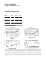
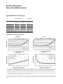
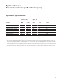
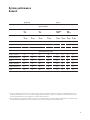
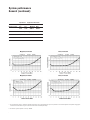
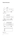
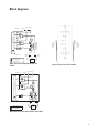
Agilent 87050E
50 Ohm Multiport Test Sets
Data Sheet
Agilent 87050E 3 MHz to 2.2 GHz
This document describes the performance and features of Agilent Technologies 87050E 50 ohm multiport test sets, both as standalone units and when
combined with 50 ohm 8712ET, 8712ES, 8714ET, or
8714ES network analyzers. The following options
are available:
• Option 004 (4 ports)
• Option 008 (8 ports)
• Option 012 (12 ports)
For more information about these test sets, please
read the following documents:
• Agilent 87050E, brochure,
literature number, 5968-4763E
• Agilent 87050E, configuration guide,
literature number, 5968-4765E
Introduction
All specifications and characteristics apply over a
25 °C ± 5 °C range (unless otherwise stated) and
30 minutes after the instrument has been turned on.
Definitions
Specification:
Warranted performance. Specifications include
guardbands to account for the expected statistical
distribution, measurement uncertainties, and
changes in performance due to environmental conditions.
Characteristic:
A performance parameter that the product is
expected to meet before it leaves the factory, but is
not verified in the field and is not covered by the
product warranty. A characteristic includes the
same guardbands as a specification.
Typical:
Expected performance of an average unit. A typical
does not include guardbands. It is not covered by
the product warranty.
Nominal:
A general, descriptive term that does not imply a
level of performance. It is not covered by the product warranty.
Supplemental information:
May include typical, nominal, or characteristic values.
Calibration:
The process of measuring known standards from a
calibration kit to characterize the systematic
(repeatable) errors of a network analyzer.
3
5
8
9
12
13
14
15
16
2
Corrected (residual) performance:
Indicates performance after error correction (calibration). It is determined by the quality of calibration standards and how well “known” they are,
plus system repeatability, stability, and noise.
Uncorrected (raw) performance:
Indicates instrument performance without error
correction. The uncorrected performance affects
the stability of a calibration.
System performance:
Performance of a complete multiport test system,
which includes an 87050E test set and an 8712ET/
ES or 8714ET/ES network analyzer.
Test Set Cal:
The calibration of a multiport test system, requiring the connection of known calibration standards
to all of the ports that will be used for measurements.
SelfCal:
An automated system calibration that uses calibration standards internal to the test set and the most
recent Test Set Cal data to calibrate the test system.
Environmental specifications:
Environmental specifications bound the external
conditions for which the specifications are valid.
The environmental specifications also bound the
external conditions the test set may be subject to
without permanently affecting performance or
causing physical damage.
Table of contents
System performance, two-port calibration
System performance, T/R calibration
System performance, uncorrected
System performance, general
Test set input/output performance
Test set general information
Physical dimensions
Block diagrams
System features
System performance
Two-port calibration (user)
Agilent 85032B/E Type-N calibration kit
Specification1 (dB)
Parameter
3 MHz
to 1.3 GHz
Typical2 (dB)
1.3 GHz
to 2.2 GHz
2.2 GHz
to 3 GHz
Directivity
47
40
37
Source match
37
35
30
Load match
47
40
37
Reflection tracking
±0.1
±0.1
±0.2
Transmission tracking
±0.1
±0.1
±0.2
Transmission uncertainty (typical)3
Magnitude
Magnitude
Phase
Phase
1. These specifications and supplementals apply under the following conditions: measurement uses the “Fine” (15 Hz) bandwidth, no averaging, and isolation cal “on”; Test Set
Cals use the “Fine” (15 Hz) bandwidth, 16 averages, and assume an isolation calibration has been performed; the test set must be used with an 8712ES or 8714ES network analyzer with firmware revision E.06.00 or later; the test set and the analyzer must have had their performance verified within the last year; both instruments must have warmed up
for at least 30 minutes after turn-on; measurements are made at an environmental temperature of 25 °C ± 5 °C and within ± 1 °C of the last valid Test Set Cal.
2. Corrected system performance is changed to typical when the current temperature has drifted beyond ± 1 °C of the last valid Test Set Cal. Typicals are valid only when the current temperature is within 25 °C ± 5 °C, and within ± 1 °C of the most recent SelfCal.
3. These uncertainty curves only include the effects of the test port(s) within the measurement path. The effect of the uncorrected match of test ports outside the measurement
path is ignored, and is dependent on the isolation between the ports of the DUT that are within the measurement path and ports of the DUT that are outside the measurement
path.
3
System performance
Two-port calibration (user)
Agilent 85033D 3.5mm calibration kit
Specification1 (dB)
Typical2 (dB)
Parameter
3 MHz
to 1.3 GHz
1.3 GHz
to 2.2 GHz
2.2 GHz
to 3 GHz
Directivity
40
38
35
Source match
38
35
30
Load match
40
38
35
Reflection tracking
±0.1
±0.1
±0.2
Transmission tracking
±0.1
±0.1
±0.2
Transmission uncertainty (typical)3
Magnitude
Magnitude
Phase
Phase
1. These specifications and supplementals apply under the following conditions: measurement uses the “Fine” (15 Hz) bandwidth, no averaging, and isolation cal “on”; Test Set
Cals use the “Fine” (15 Hz) bandwidth, 16 averages, and assume an isolation calibration has been performed; the test set must be used with an 8712ES or 8714ES network
analyzer with firmware revision E.06.00 or later; the test set and the analyzer must have had their performance verified within the last year; both instruments must have
warmed up for at least 30 minutes after turn-on; measurements are made at an environmental temperature of 25 °C ± 5 °C and within ± 1 °C of the last valid Test Set Cal.
2. Corrected system performance is changed to typical when the current temperature has drifted beyond ± 1 °C of the last valid Test Set Cal. Typicals are valid only when the current temperature is within 25 °C ± 5 °C, and within ± 1 °C of the most recent SelfCal.
3. These uncertainty curves only include the effects of the test port(s) within the measurement path. The effect of the uncorrected match of test ports outside the measurement
path is ignored, and is dependent on the isolation between the ports of the DUT that are within the measurement path and ports of the DUT that are outside the measurement
path.
4
System performance
Transmission/reflection (T/R) calibration (user)
Agilent 85032B/E Type-N calibration kit
Parameter
Specification1 ( dB)
Typical2 (dB)
3 MHz
to 1.3 GHz
1.3 GHz
to 2.2 GHz
3 MHz
to 1.3 GHz
1.3 GHz
to 2.2 GHz
2.2 GHz
to 3 GHz
Directivity
47
40
—
—
40
Source match
37
32
—
—
30
Load match (reflection calibration)
18
18
23
24
20
Load match (transmission calibration)
14
14
18
18
14
Reflection tracking
±0.1
±0.1
—
—
±0.2
Transmission tracking
±0.1
±0.1
—
—
±0.2
1. These specifications and supplementals are valid for reflection (one-port) and transmission (enhanced-response) Test Set Cals, and apply under the following conditions: measurement uses the “Fine” (15 Hz) bandwidth, no averaging, and isolation cal “on”; Test Set Cals use the “Fine” (15 Hz) bandwidth, 16 averages, and assume an isolation calibration has been performed; the test set must be used with an 8712ET, 8712ES, 8714ET, or 8714ES network analyzer with firmware revision E.06.00 or later; the test set and the
analyzer must have had their performance verified within the last year; both instruments must have warmed up for at least 30 minutes after turn-on; measurements are made at
an environmental temperature of 25 °C ± 5 °C and within ± 1 °C of the last valid Test Set Cal.
2. Corrected system performance is changed to typical when the current temperature has drifted beyond ± 1 °C of the last valid Test Set Cal. Typicals are valid only when the current temperature is within 25 °C ± 5 °C, and within ± 1 °C of the most recent SelfCal.
5
System performance
Transmission/reflection (T/R) calibration (user)
Agilent 85032B/E Type-N calibration kit
(continued)
Transmission uncertainty, enhanced response calibration
(typical)1
Magnitude, ES models
Phase, ES models
Magnitude, ET models with attenuator
Phase, ET models with attenuator
Magnitude, ET models without attenuator
Phase, ET models without attenuator
1. These uncertainty curves only include the effects of the test port(s) within the measurement path. The effect of the uncorrected match of test ports outside the measurement
path is ignored, and is dependent on the isolation between the ports of the DUT that are within the measurement path and ports of the DUT that are outside the measurement
path.
6
Agilent 85032B/E Type-N calibration kit
Magnitude, ES models
Magnitude, ET models with attenuator
Magnitude, ET models without attenuator
Phase, ES models
Phase, ET models with attenuator
Phase, ET models without attenuator
1. These uncertainty curves only include the effects of the test port(s) within the measurement path. The effect of the uncorrected match of test ports outside the measurement
path is ignored, and is dependent on the isolation between the ports of the DUT that are within the measurement path and ports of the DUT that are outside the measurement
path.
7
System performance
Uncorrected
Type-N
Specification1 ( dB)
Typical (dB)
Parameter
3 MHz
to 1.3 GHz
1.3 GHz
to 2.2 GHz
3 MHz
to 1.3 GHz
1.3 GHz
to 2.2 GHz
2.2 GHz
to 3 GHz
Source match, ratioed
12
10
17
14
11
Load match, test port unselected2
18
18
23
24
20
Load match, test port selected3
12
12
16
17
13
Transmission tracking4
—
—
±3
±2.5
±3
Reflection tracking4
—
—
±3
±2.5
±3
Crosstalk5, 8712ET/8714ET
—
—
93
89
81
Crosstalk5, 8712ES/8714ES
—
—
83
79
71
1. These specifications and supplementals apply under the following conditions: measurement uses the “Fine” (15 Hz) bandwidth, with narrowband detection and no averaging;
the test set must be used with an 8712ET, 8712ES, 8714ET, or 8714ES network analyzer with firmware revision E.06.00 or later; the test set and the analyzer must have had
their performance verified within the last year; both instruments must have warmed up for at least 30 minutes after turn-on.
2. This is the match of any test port that is unselected (not in the measurement path). If the network analyzer is performing a reflection measurement with one-port calibration,
then only one port on the test set is selected (the source port). If the network analyzer is performing a transmission measurement or a reflection measurement with two-port
calibration, then only two ports on the test set are selected (the source and load ports).
3. This is the match of the test set port that has been selected as the load port. The network analyzer must be making a transmission measurement or a reflection measurement
with two-port calibration for a test port to be selected as the load port.
4. The uncorrected tracking terms are defined as the deviation over the defined frequency band, ignoring offset loss.
5. Crosstalk is computed by normalizing the result of an isolation measurement to a through measurement between the two ports such that the path losses are taken into
account. Isolation is defined as the transmission signal measured between any two ports of the test system when those two ports are terminated with shorts.
8
System performance
General
Specification
Typical
System bandwidth
Fine
15 Hz
Network analyzer
3 MHz
to
1.3 GHz
Fine
15 Hz
1.3 GHz
to
2.2 GHz
3 MHz
to
1.3 GHz
Med Wide
4000 Hz
1.3 GHz
to
2.2 GHz
Wide
6500 Hz
3 MHz
to
1.3 GHz
1.3 GHz
to
2.2 GHz
3 MHz
to
1.3 GHz
1.3 GHz
to
2.2 GHz
System noise floor1 (dBm)
8712ET/8714ET
–97
–95
–106
–103
–82
–79
–42
–39
8712ES/8714ES
–88
–86
–100
–97
–75
–72
–42
–39
System dynamic range2 (dB)
8712ET, no attenuator
101
97
112
108
87
83
49
45
8712ET, with attenuator
100
96
111
107
86
82
48
44
8712ES
89
85
103
99
78
74
45
41
8714ET, no attenuator
99
95
109
105
84
80
46
42
8714ET, with attenuator
97
93
108
104
83
79
45
41
8714ES
86
82
100
96
81
77
42
38
1. Noise floor is defined as the rms value of the trace (in linear format) for a transmission measurement in CW mode, using the “Fine” bandwidth (15 Hz), the test ports
terminated in loads, 0 dBm at the test set source port, and no averaging. This measurement ignores the effects of crosstalk. This is a system specification–the test set
increases the network analyzer noise floor by adding loss to the network analyzer measurement.
2. The system dynamic range is calculated as the difference between the receiver minimum input (noise floor plus calibrated crosstalk) and the system’s maximum output
power. System dynamic range applies to transmission measurements only, since reflection measurements are limited by directivity.
9
System performance
General (continued)
Specification
Supplemental information
System bandwidth
Network analyzer
Fine
Fine
Med Wide
Wide
15 Hz
15 Hz
4000 Hz
6500 Hz
Receiver dynamic range1 (dB)
8712ET/8714ET
115
121
96
58
8712ES/8714ES
106
115
90
57
Magnitude, ES models
Phase, ES models
Magnitude, ET models
Phase, ET models
1. The receiver dynamic range is calculated as the difference between the receiver minimum input (noise floor) and the receiver maximum input. Receiver dynamic range applies
to transmission measurements only, since reflection measurements are limited by directivity.
2. The reference power for dynamic accuracy is –20 dBm.
10
Network analyzer
Specification
Characteristic (dBm)
Output power (system maximum)
<1 GHz
>1 GHz
8712ET, no attenuator
—
10.5
7
8712ET, with attenuator
—
9.5
6
8712ES
—
7.5
4
8714ET, no attenuator
—
5.5
2
8714ET, with attenuator
—
4.5
1
8714ES
—
3.5
–1
Parameter
Specification
Supplemental information
Port switching time1 (sec)
Reflection calibration
—
0.7
Transmission enhanced calibration
—
0.7
Two-port calibration
—
0.7
SelfCal time2 (sec)
Reflection calibration
—
1 (typical)
Transmission enhanced calibration
—
3 (typical)
Two-port calibration
—
8 (typical)
1. This is the time required to switch to any new port configuration, and requires that the Test Set Cal has been performed for 201 points, the new measurement configuration is
201 points, and no new SelfCal occurs during switching.
2. This is the time required to perform the SelfCal for any single port configuration, assuming that the Test Set Cal was performed for 201 points, the new measurement configuration is 201 points, and the measurement bandwidth is “Med Wide” (4000 Hz). SelfCal times for other settings can be found in Table 4-1 of the Agilent 87050E/87075C Users
and Service Guide (87050-90026).
11
Test set input/output performance
Parameter
Specification
Frequency range
3 MHz to 2.2 GHz
Supplemental
—
RF input power
Maximum input power
at 0.1 dB compression1
—
16 dBm (nominal)
Input damage power
—
20 dBm (characteristic)
Parameter
Specification (dB)
Typical (dB)
3 MHz
to 1.3 GHz
1.3 GHz
to 2.2 GHz
3 MHz
to 1.3 GHz
1.3 GHz
to 2.2 GHz
2.2 GHz
to 3 GHz
Source match, test port2
14
11
18
15
12
Load match, test port unselected3
18
18
23
24
20
Load match, test port selected4
14
14
18
18
14
Interconnect match, reflection port5
12
10
17
15
10
Interconnect match, transmission port5
11
8
14
13
11
Insertion loss, reflection port to port-n6
7.5
9.5
6
8
12
Insertion loss, transmission port to port-n6
7.5
9.5
6
8
12
Tracking, reflection port to port-n6
—
—
1.5
1.2
1.5
Tracking, transmission port to port-n6
—
—
1.5
1.2
1.5
Crosstalk, uncalibrated, adjacent ports7
90
90
100
95
85
Crosstalk, uncalibrated, non-adjacent ports7
90
90
105
100
90
1. Compression is defined for the test set, independent of the network analyzer.
2. This is the match of the test set port that has been selected as the source port. The test set interconnect reflection port must be terminated with a load standard from an
Agilent 85032B/E calibration kit.
3. This is the match of any test port that is unselected (not in the measurement path). Only the source port of the test set is selected when you make a reflection measurement
with one-port calibration. Only the source and load ports of the test set are selected when you make a transmission measurement, or a reflection measurement with two-port
calibration.
4. This is the match of the test set port that has been selected as the load port. A transmission or two-port measurement is required for a test port to be selected as the load port.
The test set interconnect transmission port must be terminated with a load standard from an 85032B/E calibration kit.
5. This is the match of the test set interconnect ports (transmission and reflection ports) with the test set in transmission, or two-port mode. The selected test set test ports must
be terminated with load standards from 85032B/E calibration kits.
6. The reflection and transmission ports of the test set are connected to the corresponding ports of the network analyzer. Port-n is any one of the test ports used to connect to
the device-under-test.
7. This is crosstalk of the test set measured between the test set’s interconnect ports, with shorts on the selected test ports. Crosstalk is computed by normalizing the result of
an isolation measurement to a through measurement between the two ports such that the path losses are taken into account. Isolation is defined as the transmission
signal measured between any two ports of the test system when these two ports are terminated with shorts.
12
Test set general information
Description
Specification
Supplemental information
87050E, Option 004
4
Type-N, female 50Ω (nominal)
87050E, Option 008
8
Type-N, female 50Ω (nominal)
87050E, Option 012
12
Type-N, female 50Ω (nominal)
Parallel in connector
—
25-pin D-subminiature female (DB-25)
Parallel out connector
—
25-pin D-subminiature female (DB-25)
Front panel ports
Real panel
Line power1
Frequency 50/60 Hz
—
Input voltage, operating
100/120/220/240 Vac
Input power
—
—
<45 W (typical)
General environment
ESD
—
Minimize using static-safe work procedures and
an antistatic bench mat
(Part number 9300-0797)
Dust
—
Minimize for optimum reliability
General
Indoor use only
—
Operating Temperature
0 °C to + 55 °C
—
Storage Temperature
–40 °C to + 70 °C
—
Altitude
0 to 4.5 km (15,000 ft)
Cabinet dimensions
Height x width x depth
—
132.8 x 425 x 497 mm (nominal)
5.2 x 16.7 x 19.6 in (nominal)
Cabinet dimensions exclude front and
rear protrusions
Weight
Net
—
8 kg (18 lb) (nominal)
Shipping
—
11 kg (24 lb) (nominal)
1. A third-wire ground is required.
13
Physical dimensions
Physical dimensions of the Agilent 87050E Option 004
multiport test set1
Physical dimensions of the Agilent 87050E Option 008
multiport test set1
Physical dimensions of the Agilent 87050E Option 012
multiport test set1
1. These dimensions exclude rear protrusions.
14
Block diagrams
REAR PANEL
AUX Input
External Detectors
Y
X
Y
Input B
RF
Source
ADC and Processor
Input B*
X
Incident
Reference
Input R*
Input A
Transmission
Input R
Reflected
CRT
FRONT PANEL
Reflection
(RF Out)
With Attenuator Option 1E1
Transmission
(RF In)
Device
Under
Test
Narrowband Detector
Broadband Detector
Block diagram for the Agilent 87050E
(only one test set port pair is shown)
Block diagram for the Agilent 8712ET and
8714ET
REAR PANEL
AUX Input
External Detectors
Y
X
Y
Input B
RF
Source
Input B*
ADC and Processor
X
Input R
Reference
Input R*
Input A
CRT
FRONT PANEL
Narrowband Detector
Port 1
Port 2
Device
Under
Test
Broadband Detector
Block diagram for the Agilent 8712ES and 8714ES
15
System features
Test set control
Control of the switches inside the test set and calibration of the test system can be accomplished
from the front panel of the network analyzer—an
external computer is not required. However, the
analyzers are fully programmable for use in automated test environments.
Measurement
Number of display measurements
Two measurement displays are available, with
independent control of display parameters including format type, scale per division, reference level,
reference position, and averaging. The displays can
share network analyzer sweep parameters, or, by
using alternate sweep, each measurement can have
independent sweep parameters including frequency settings, IF bandwidth, power level, and number
of trace points. The instrument can display a single
measurement, or dual measurements on a split
(two graticules) or overlaid (one graticule) screen.
Measurement choices
• Narrowband
ET models: reflection (A/R), transmission (B/R),
A, B, R
ES models: S11 (A/R), S22 (B/R), S21 (B/R),
S12 (A/R), A, B, R
• Broadband
X, Y, Y/X, X/Y, Y/R*, power (B*, R*), conversion
loss
(B*/R*)
Note: X and Y denote external broadband-detector inputs; * denotes internal broadband detectors.
Formats
Log or linear magnitude, SWR, phase, group delay,
real and imaginary, Smith chart, polar, and impedance magnitude
Trace functions
Current data, memory data, memory with current
data, division of data by memory
Display annotations
Start/stop, center/span, or CW frequency, scale per
division, reference level, marker data, softkey
labels, warning and caution messages, screen titles,
time and date, and pass/fail indication
16
Limits
Measurement data can be compared to any combination of line or point limits for pass/fail testing.
User-defined limits can also be applied to an amplitude- or frequency-reference marker. A limit-test
TTL output is available on the rear panel for external control or indication. Limits are only available
with rectilinear formats.
Data markers
Each measurement channel has eight markers.
Markers are coupled between channels. Any one of
eight markers can be the reference marker for delta-marker operation. Annotation for up to four
markers can be displayed at one time.
Marker functions
Markers can be used in absolute or delta modes.
Other marker functions include marker to center
frequency, marker to reference level, marker to
electrical delay, searches, tracking, and statistics.
Marker searches include marker to maximum,
marker to minimum, marker to target value, bandwidth, notch, multi-peak and multi-notch. The
marker-tracking function enables continuous
update of marker search values on each sweep.
Marker statistics enable measurement of the mean,
peak-to-peak and standard deviation of the data
between two markers. For rapid tuning and testing
of cable-TV broadband amplifiers, slope and flatness functions are also available.
Storage
Internal memory
1.5 Mbytes (ET models) or 1 Mbyte (ES models) of
nonvolatile storage is available to store instrument
states, measurement data, screen images, and
IBASIC programs. Instrument states can include
all control settings, limit lines, memory data, calibration coefficients, and custom display titles. If no
other data files are saved in nonvolatile memory,
between approximately 20 and 150 instrument
states can be saved (depending on the model type
and on instrument parameters). Approximately 14
Mbytes of volatile memory are also available for
temporary storage of instrument states, measurement data, screen images, and IBASIC programs.
Disk drive
Trace data, instrument states (including calibration data), and IBASIC programs can be saved on
floppy disks using the built-in 3.5 inch disk drive.
All files are stored in MS-DOS®-compatible format.
Instrument data can be saved in binary or ASCII
format (including Touchstone/.s2p format), and
screen graphics can be saved as PCX (bit-mapped),
HP-GL (vector), or PCL5 (printer) files.
NFS: See description under Control via LAN
Data hard copy
Hard copy prints can be made using PCL and PCL5
printers (such as HP DeskJet or LaserJet series
printers), or Epson-compatible graphics printers.
Single color and multicolor formats are supported.
Hard copy plots can be automatically produced
with HP-GL-compatible plotters such as the Agilent
7475A, or with printers that support HP-GL. The
analyzer provides Centronics (parallel), RS-232C,
GPIB, and LAN interfaces.
Automation
Controlling via GPIB
Interface
The GPIB interface operates to IEEE 488.2 and
SCPI standard-interface commands.
Control
The analyzer can either be the system controller, or
pass bus control to another active controller.
Data transfer formats
• ASCII
• 32- or 64-bit IEEE 754 floating-point format
• Mass-memory-transfer commands allow file
transfer between external controller and analyzer.
Control via LAN
The built-in LAN interface and firmware support
data transfer and control via direct connection to a
10 Base-T (Ethertwist) network. A variety of standard protocols are supported, including TCP/IP,
sockets, ftp, http, telnet, bootp, and NFS. The LAN
interface is standard.
SCPI
The analyzer can be controlled by sending
Standard Commands for Programmable
Instruments (SCPI) within a telnet session or via a
socket connection and TCP/IP (the default socket
port is 5025). The analyzer’s socket applications
programming interface (API) is compatible with
Berkeley sockets, Winsock and other standard
socket APIs. Socket programming can be done in a
variety of environments including C programs,
Agilent VEE, SICL/LAN, or a Java™ applet. A standard web browser and the analyzer’s built-in web
page can be used to remotely enter SCPI commands via a Java applet.
FTP
Instrument state and data files can be transferred
via ftp (file-transfer protocol). An internal, dynamicdata disk provides direct access to instrument
states, screen dumps, trace data, and operating
parameters.
HTTP
The instrument’s built-in web page can be accessed
with any standard web browser using http (hypertext transfer protocol) and the network analyzer’s
IP address. The built-in web page can be used to
control the network analyzer, view screen images,
download documentation, and link to other sites
for firmware upgrades and VXIplug&play drivers.
Some word processor and spreadsheet programs,
such as Microsoft® Word 97 and Excel 97, provide
methods to directly import graphics and data via a
LAN connection using http and the network analyzer’s IP address.
SICL/LAN
The analyzer’s support for SICL (standard instrument control library) over the LAN provides control of the network analyzer using a variety of computing platforms, I/O interfaces, and operating systems. With SICL/LAN, the analyzer is controlled
remotely over the LAN with the same methods
used for a local analyzer connected directly to the
computer via a GPIB interface. SICL/LAN protocol
also allows the use of Agilent’s free VXI plug&play
driver to communicate with the multiport test system over a LAN. SICL/LAN can be used with
Windows® 95/98/NT, or HP-UX.
17
System features (continued)
NFS
The analyzer’s built-in NFS (network file system)
client provides access to remote files and directories using the LAN. With NFS, remote files and
directories (stored remotely on a computer) behave
like local files and directories (stored locally within
the analyzer). Test data taken by the network analyzer can be saved directly to a remote PC or
UNIX® directory, eliminating the need for a
remotely initiated ftp session. For Windows-based
applications, third-party NFS-server software must
be installed on the PC. NFS is fully supported in
most versions of UNIX.
The Test Set Cal and SelfCal features on your multiport test system increase the accuracy of your
measurements and significantly increase the test
efficiency of your work stations by eliminating frequent and lengthy calibration procedures.
Bootp
Bootstrap protocol (bootp) allows a network analyzer to automatically configure itself at power-on
with the necessary information to operate on the
network. After a bootp request is sent by the analyzer, the host server downloads an IP and gateway
address, and a subnet mask. In addition, the analyzer can request an IBASIC file, which automatically executes after the transfer is complete. For
Windows-based applications, third-party bootpserver software must be installed on the PC.
Bootp is fully supported in most versions of UNIX.
Test Set Cal for the Agilent 8712ET and Agilent 8714ET
analyzers
The data collected by the analyzer during a Test
Set Cal always includes both transmission
(enhanced response) calibration data and reflection (one-port) calibration data. When making
measurements after calibration, the analyzer automatically recalls and uses the correct set of calibration data for the type of measurement chosen.
Programming with IBASIC
As a standard feature, all Agilent 8712ET/ES and
8714ET/ES network analyzers come with the
Instrument BASIC programming language
(IBASIC). IBASIC facilitates automated measurements and control of other test equipment, improving productivity. For simpler applications, you can
use IBASIC as a keystroke recorder to easily automate manual measurements. Or, you can use an
optional, standard PC keyboard to write custom
test applications that include:
•
•
•
•
•
Special softkey labels
Tailored user prompts
Graphical setup diagrams
Barcode-reading capability
Control of other test instruments via the GPIB,
serial, or parallel interfaces
Measurement calibration
Measurement calibration is a process that
improves measurement accuracy by using errorcorrection arrays to remove systematic measurement errors.
18
Test Set Cal
A Test Set Cal is a calibration that should be performed on a regular, but relatively infrequent basis
(at least once a month is recommended). A Test
Set Cal requires connection of mechanical calibration standards to all of the ports you will be using
for your measurements.
Test Set Cal for the Agilent 8712ES and 8714ES analyzers
The S-parameter network analyzers perform either
two-port calibration or enhanced response/oneport calibration. Choosing a two-port calibration
for the Test Set Cal removes the most systematic
errors, giving you the greatest measurement accuracy. Choosing the enhanced response/one-port
calibration allows faster measurement speeds, but
is not as accurate as full two-port calibration.
SelfCal
A SelfCal is an internal system calibration that
automatically executes in just a few seconds on a
regular, frequent basis (once per hour is recommended). A SelfCal does not require that you
remove your DUT or that you make any connections of external calibration standards. The SelfCal
uses the results of the most recent Test Set Cal,
along with current measurements of internal, electronically switched, open, short, load and through
standards. SelfCal removes the drift of the network
analyzer and multiport test set due to environmental variations.
Other calibrations
Besides using a Test Set Cal, individual instrument
states and their corresponding calibrations can be
saved and recalled for use with specific measurement paths. For example, to improve measurement
throughput, one signal path could be tested using a
response calibration, while all other paths are tested
with a Test Set Cal using two-port calibration.
Note: the SelfCal feature is only supported with
Test Set Cals.
A variety of calibration types are available and
described below:
ES models only
• Two-port calibration
Compensates for frequency response, source
and load match, and directivity errors while
making S-parameter measurements of transmission (S21, S12) and reflection (S11, S22).
Compensates for transmission crosstalk when
the Isolation on OFF softkey is toggled to ON.
Requires short, open, load, and through standards.
ET and ES models: transmission measurements
• Normalization
Provides simultaneous magnitude and phase
correction of transmission frequency-response
errors. Requires a through connection. Used for
both narrowband and broadband detection.
Does not support calibration interpolation.
• Response
Simultaneous magnitude and phase correction
of frequency response errors for transmission
measurements. Requires a through standard.
• Response and isolation
Compensates for frequency response and crosstalk errors. Requires a load termination on both
test ports and a through standard.
• Enhanced response
Compensates for frequency response and source
match errors. Requires short, open, load, and
through standards.
ET and ES models: reflection measurements
• One-port calibration
Compensates for frequency response, directivity,
and source-match errors. Requires short, open,
and load standards.
Calibration kits
Data for several standard calibration kits are
stored in the instrument for use by the calibration
routines. They include:
•
•
•
•
3.5 mm (85033D)
Type-N (85032B/E)
7 mm (85031B)
7-16 (85038A)
In addition, you can also describe the standards
for a user-defined calibration kit (for example,
open-circuit capacitance coefficients, offset-short
length, or through-standard loss).
For more information about calibration kits available from Agilent Technologies, consult the Agilent
87050E Configuration Guide, Agilent literature
number 5968-4765E.
Key network analyzer options
Step attenuator (Option 1E1)
Adds a built-in 60 dB step attenuator to transmission/reflection (ET) models to extend the output
power range to –60 dBm. The attenuator is standard in S-parameter (ES) models.
19
www.agilent.com
Agilent Email Updates
www.agilent.com/find/emailupdates
Get the latest information on the
products and applications you select.
Java is a U.S. trademark of Sun
Microsystems, Inc.
Microsoft, MS-DOS, Windows, Windows 95,
Windows 98, Windows NT, Word 97, and
Excel 97 are U.S. registered trademarks of
Microsoft Corporation.
UNIX is a registered trademark of the
Open Group.
Remove all doubt
Our repair and calibration services will
get your equipment back to you, performing like new, when promised. You
will get full value out of your Agilent
equipment through-out its lifetime.
Your equipment will be serviced by Agilent-trained technicians using the latest factory calibration procedures, automated repair diagnostics and genuine
parts. You will always have the utmost
confidence in your measurements.
For information regarding self maintenance of this product, please
contact your Agilent office.
Agilent offers a wide range of additional expert test and measurement
services for your equipment, including
initial start-up assistance, onsite education and training, as well as design,
system integration, and project management.
For more information on repair and
calibration services, go to:
www.agilent.com/find/removealldoubt
Product specifications and descriptions
in this document subject to change
without notice.
For more information on Agilent
Technologies’ products, applications
or services, please contact your local
Agilent office. The complete list is
available at:
www.agilent.com/find/contactus
Americas
Canada
Latin America
United States
(877) 894-4414
305 269 7500
(800) 829-4444
Asia Pacific
Australia
China
Hong Kong
India
Japan
Korea
Malaysia
Singapore
Taiwan
Thailand
1 800 629 485
800 810 0189
800 938 693
1 800 112 929
0120 (421) 345
080 769 0800
1 800 888 848
1 800 375 8100
0800 047 866
1 800 226 008
Europe & Middle East
Austria
01 36027 71571
Belgium
32 (0) 2 404 93 40
Denmark
45 70 13 15 15
Finland
358 (0) 10 855 2100
France
0825 010 700*
*0.125 €/minute
Germany
07031 464 6333
Ireland
1890 924 204
Israel
972-3-9288-504/544
Italy
39 02 92 60 8484
Netherlands
31 (0) 20 547 2111
Spain
34 (91) 631 3300
Sweden
0200-88 22 55
Switzerland
0800 80 53 53
United Kingdom 44 (0) 118 9276201
Other European Countries:
www.agilent.com/find/contactus
Revised: March 24, 2009
© Agilent Technologies, Inc. 2009
Printed in USA, April 15, 2009
5968-4764E


![[Définitions]](http://vs1.manualzilla.com/store/data/006462331_1-6fa0e31a4b2797bb83313f78233fa294-150x150.png)