1
Congratulations for selecting this Radio Shack
Computer product!
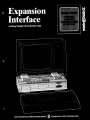
The TRS-80 Expansion Interface greatly enhances the power
and usefulness of your LEVEL II TRS-80 Computer. With it,
you can connect a wide variety of external components
("peripherals") to your Computer - printers, mass storage
devices, communications equipment, voice synthesizers, speech
recognition devices, custom-made I/O devices, etc.
Just as importantly, the Expansion Interface lets you add
Random Access Memory, so your System can hold longer
programs and process more data at once. Once you have filled
your TRS-80 with RAM (16K), you can add either 16K or 32K
to the Expansion Interface, for a total of either 32K or 48K.
( 1K = 1024 memory locations or bytes.)
This unit is shipped with no RAM ch ips installed and it has
Catalog Number 26-1140. If you up-grade your Expansion
Interface to 16K RAM, you'll have a 26-1141; and if you upgrade your unit to the full 32K RAM, you'll have a 26-1142.
Here's a brief description of the connections your Interface
provides:
• DIN jacks for two Cassette Recorders - to let you read data
from one unit and write to the other
• Line Printer Card-Edge for connection to Radio Shack Line
Printers and other su itable parallel interface printers
• Mini-Disk Card-Edge for connection of up to four Radio Shack
Mini-Disk Drives
• Expansion Board Card-Edge for use when you add the
RS-232-C Interface (or other custom-designed PCB) to the
built-in expansion compartment
• Bus Card-Edge, which duplicates the signals present at the
TRS-80 Card-Edge.
In addition to allowing all these connections, the Expansion
Interface provides a 25 mS heartbeat interrupt to the Computer,
which you can use to provide the "tick" for a Real-Time clock
routine.
Notes: Don't connect the Expansion Interface to a LEVE L I
TRS-80. The two are not compatible.
This manual pertains to Expansion Interface units whose serial
numbers begin with 035000 (for 26-1140), and 008000 (for
both 26-1141 and 26-1142).
© Copyright 1979 by Radio Shack, A Division of Tandy Corporation, Ft. Worth, TX 76102
Contents
SETTING UP
Installing the Power Supplies .. . . . . . . . . . . . . . . . . . . . . . . . 3
Cables, Card-Edges and JaGks
, 4
Connection to the TRS-80
; . . .. 6
Power-Up and Notes
8
10
Adding RAM
PERIPHERALS
Dual Cassettes
Line Printer
Mini-Disk(s)
12
, 14
16
Bus~ompatible Devices . . . . . . . . . . . . . . . . . . . . . . . . . . .. 16
Expansion Board
16
TECHNICAL INFORMATION
25 mS Heartbeat Interrupt . . . . . . . . . . . . . . . . . . . . . . . . ..
Floppy Disk Controller IC ... . . . . . . . . . . . . . . . . . . . . . ..
Address Decoding Scheme . . . . . . . . . . . . . . . . . . . . . . . . ..
Cassette Jack Signals
Line Printer Card-Edge Signals . . . . . . . . . . . . . . . . . . . . . ..
Mini-Disk Card-Edge Signals. . . . . . . . . . . . . . . . . . . . . . . ..
Bus Card-Edge Signals
Expansion Board Card-Edge Signals . . . . . . . . . . . . . . . . . ..
20
24
25
26
28
29
30
31
TROUBLESHOOTING
Reference Materials
Disassembly
Power Supply Checks and Adjustments
Schematic Diagrams
2
34
34
36
, 38
SETTING UP
Installing the Power Supplies
The Expansion Interface contains a storage compartment for two
Power Supplies - one for the Interface, the other for the TRS-80
Computer. Keeping the Supplies inside this Compartment saves space
and makes the System more "manageable".
1. The entire system should be OFF and both Power Supplies
unplugged.
2. Remove the three phillips-head screws from the Power Supply
Compartment cover (see Figure 1).
3. Look inside the compartment and locate the round, S-pin DIN
jack on the edge of the Printed Circuit Board (see the Detail in
the Figure below). Connect the DIN plug from one of the Power
Supplies to this jack. This just-connected Supply will now power
the Expansion Interface.
4. Place the Expansion Interface Power Supply inside the
Compartment as shown in Figure 1.
5. Next, place the TRS-80's Power Supply inside the Compartment
as shown in the Figure.
6. Route the three unconnected cords (two AC powercords, one DIN
cable) out of the case. Be sure to seat them in the cutouts
provided in the case.
7. Replace the Compartment Cover. Don't over-tighten the screws or
you might damage the case.
8. Connect the Power Supply DIN plug to your TRS-80's POWER
jack. But don't plug in the AC power cords until you've made all
peripheral connections.
Figure 1. Power Supply installation.
3
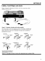
SETTING UP
Cables, Card-Edges and Jacks
Figure 2 shows the Expansion Interface with the connection cables
supplied with the unit.
Figure 2. Expansion Interface with cables supplied.
You also receive connector hoods for all the card-edges, including the
one on the left rear of your TRS-80. Be sure to use the hoods for the
cable connectors. They act as keyways to help you to avoid the
misalignment of pins.
TRS-BO CARD EDGE
H~OOO
PIN 8719011 \
lAs-eo /INTERFACE
CARD EDGE HOOD
eXPANSION BOARD
CARD EDGE HOOD
PIN 8719012
PIN 8719014
.A. ~::::-~"~"
CONNECTOR
/~7" ~/
BUFFERED INTERFACE BUS
CARD EDGE HOOD
PIN 8719014
MINI·D1SK
CARD EDGE HOOD
PIN 8719013
CONNECTOR
AND CABLE
• NOTE: LINE PRINTER CABLES ARE SHIPPED BY THE
MANUFACTURER. SOME LINE PRINTERS USE A FLAT
RIBBON CABLE INSTEAD OF THE TWISTED WIRE
(ROUND) TYPE CABLE. USE THE CABLE PROVIDED
WITH YOUR LINE PRINTER.
Figure 3. Card-edge connector hoods with replacement part numbers (PIN).
4
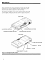
SETTING UP
Figure 4 identifies the various card-edges and jacks. Note that the
card-edges are concealed behind protective cover-plates. Don't
remove a cover unless you plan to use that card-edge.
To remove a cover-plate: press in on the right side of the plate until
it pivots slightly. Then grasp the left side of the plate and pull out.
(FRONT VIEW)
TR5-S0 INTERFACE CARD EDGE
TR5-S0 BUS EXTENSION CARD EDGE
(REAR VIEW)
TRs-BO CASSETTE - I/O JACK
Figure 4. Card-edge and jack location.
5
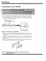
SETTING UP
Connection to the TRS-80
1. Position the TRS-80 as illustrated (Figure 5, rear view). Lift the
door covering the Expansion Card-Edge, and slide it slightly to
the right, then lift it up and away from the TRS-80 (be careful not
to break the little plastic tabs).
REMOVE DOOR OVER
TRS-BO EXPANSION CARD EDGE
I
CONNECTOR AND CABLE
Figure 5. Connection to the TRS-aO.
2. Attach one end of the TRS80/Expansion Interface cable to the
TRS-80 Card-Edge, with the cable exiting from the bottom of the
connector.
3. Attach the curved TRS-80 connector hood to the keyboard case;
the ribbon cable should feed out from the bottom of the hood
(Figure 5).
4. Attach a flat hood onto the other end of the cable, with the cable
exiting from the bottom of the hood (Figure 6).
Figure 6. Place hood over connector with cable exiting from
bottom of hood.
6
SETTING UP
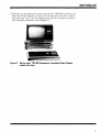
5. Position the Expansion Interface behind the TRS-80 keyboard and
place the Video Display on top of the Expansion Interface, taking
care that the "feet" on the Display lock into the recesses on top of
the Expansion Interface case (Figure 7).
Figure 7. Set up your TRS-aO/Expansion InterfaceNideo Display
system this way.
7
SETTING UP
Power-Up and Notes
With the Expansion Interface connected to the TRS-80 Computer as
explained in the last section, you are ready to tum on the
components.
Note: If you are going to connect any peripherals, do it while the
system is OFF (see Peripheral Connection). Never change the
connections to the Expansion Interface or Computer while the
Computer or Interface is ON.
1. Make all connections before you plug in the AC line cords.
2. Tum on the peripherals you are going to use.
3. Tum on the Expansion Interface, by pressing the power button
into the case until it clicks into position. Use the rubber eraser on
a pencil, or something similar. (In the on position, the button is
recessed, so you won't tum the unit off accidentally.)
4. Tum on the TRS-80 Computer.
Note: If you do not have a Mini-Disk system connected, you must
hold down the BREAK key while you tum on the Computer. If you
do have a Mini-Disk system connected, follow the power-up sequence
recommended in your Mini-Disk Operation Manual.
With some Line Printers, you must have the Printer on for TRSDOS
to load and operate.
To tum the system off, reverse the power-up sequence. That is, turn
the TRS-80 Computer off first, etc.
Caution: Tum off all peripheral equipment (Line Printer, etc.) before
turning off the Expansion Interface.
8
SETTING UP
Notes on AC Power Sources
Although your TRS-80 Micro-Computer system uses the latest in
efficient, low-current electronic devices, it is important to avoid
using household extension cords, multiple outlets or "cube-taps", etc.
Place your TRS-80 system as close as possible to standard AC power
outlets. Otherwise, line noise from the Mini-Disk, Line Printer, or
other peripherals may be transmitted through a shared line cord to
the Expansion Interface or TRS-80, causing loss of memory or
spontaneous reset.
If you cannot connect each component in your system directly to
an AC outlet, use a high-grade, heavy-duty extension cord or
multiple outlet. These are available at your local Radio Shack store.
It's also a good idea to route your AC line cords away from any of
the Input/Output cables (e.g., ribbon cable) in the system. This will
reduce the possibility of line noise being picked up by the I/O cables.
9
SETTING UP
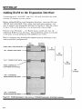
Adding RAM to the Expansion Interface
Connecting your "no RAM" unit (26-1140) will not affect the total
amount of memory in your system.
Before adding RAM to your Expansion Interface, you must fill your
TRS-80 with 16K RAM. Then, when you need more memory, you
have it added to the Expansion Interface in blocks of 16K, for a total
of up to 32K in the Interface, or a system total of up to 48K.
Preserve your Warranty - let Radio shack install and test all
additional RAM in your Interface. The installation charge is included
in the price of each additional 16K RAM kit (26-1101).
Here's a memory map showing the highest memory addresses in the
various possible configurations:
HEX
ADDRESS
DECIMAL
ADDRESS
FIRST USER RAM ADDRESS
"4K" TRS-80'S STOP HERE
}
4K
SYSTEM
16K
SYSTEM
"16 K"TRS-80'S STOP HERE
32K
SYSTEM
FIRST ADDRESS IN
EXPANSION INTERFACE
48K
SYSTEM
"16K" EXPANSION
INTERFACES STOP HERE
"32K" EXPANSION
INTERFACES STOP HERE - -
Figure 8. RAM addresses in the various TRS-80/Expansion Interface systems.
10
PERIPHERALS
Refer to Figures 2, 3 and 4 while connecting any
peripheral equipment.
11
PERIPHERALS
Dual Cassettes
By adding a second cassette recorder to your system, you'll be able
to speed up your cassette input/output operations. For example, you
can read a program or data from one recorder, edit the program or
update the data, and write it out to the other recorder - no need to
swap cassettes, rewind or reset Play and Record keys ... !
Note: If you have just one recorder, leave it connected directly to
the CASSETTE jack on the TRS-80. There is no advantage in having
a single recorder connected via the Expansion Interface.
1. Locate the Cassette Interface Cable. It has a single DIN plug at
each end.
2. Plug one end into the TRS-80 CASSETTE jack, and the other end
into the Cassette jack on the Expansion Interface (the DIN jack
next to the power cables).
3. You have two Cassette Recorder cables - one came with your
TRS-80, the other came with the Expansion Interface. Connect
one of them to the Cassette 1 DIN jack, and the other to the
Cassette 2 DIN jack.
4. Now connect the two sets of Cassette plugs to your two Recorders
as follows:
A. Black plug to the EA~ jack
B. Larger Gray plug to 1;he AUX jack
C. Smaller Gray plug to the REM jack
5. The Recorder connected to the Cassette 1 jack is now Cassette
Drive 1; the Recorder connected to Cassette 2 is now Cassette
Drive 2.
Note: Depending on which Cassette recorder(s) you have, connection
may vary. In general, use the same 3-plug arrangement you'd use in a
single-recorder system.
12
PERIPHERALS
Dual Cassette Operation
LEVEL II BASIC
To select a cassette drive with LEVEL II BASIC, use the following
statements (see the LEVEL II BASIC Reference Manual for details):
CLOAD#-l,filename
Loads a program from Cassette I
CLOAD#-2,filename
Loads a program from Cassette 2
Note: ,filename is optional - omit if you want to load the first program
encountered on the tape.
CLOAD#-l, ? filename
CLOAD#-2, ? filename
Compare program in memory with
one stored on Cassette I
Compare program in memory with
one stored on Cassette 2
Note: filename is optional again.
PRINT#-l, data
PRINT#-2, data
Note: data is a standard Print list.
Write data to Cassette I
Write data to Cassette 2
INPUT#-l, variable (s)
Input data from Cassette I
INPUT#-2, variable (s)
Input data from Cassette 2
Note: variable (s) is a standard Input list, and it must match the Print list
that wrote the data.
In the SYSTEM mode, Cassette I is always selected.
Assembly Language
To select Cassette I for an assembly language I/O routine, store zero
in hex address 37E4; To select Cassette 2, store I in hex 37E4. For
more information, refer to the Instruction Manual for the TRS-80
Editor-Assembler, Catalog Number 26-2002.
13
PERIPHERALS
Line Printer
The Line Printer Card Edge provides a parallel data interface which is
compatible with Radio Shack Line Printers. The connection cable
and instructions will be supplied with the Line Printer.
Use with Other Printers
Certain other line printers can be connected to the Line Printer Card
Edge. In general, the Printer must:
1. Be equipped with a female 34-pin connector to mate with the
Expansion Interface card-edge.
2. Accept 7- or 8-bit ASCII data in parallel format.
3. Supply the Computer with the following status signal:
BUSY (low = not busy, okay to send. High = busy, do not send.
Note: The other Printer status signals are optional, as follows:
OUT OF PAPER - If the Printer does not provide this signal,
simply ground this input to System Common (see Technical
Information later on for pin location. Not necessary for Radio
Shack Line Printers.
SELECT and FAULT - If the Printer does not supply these
signals, external resistors in the Interface will automatically pull
these inputs high, to allow normal output to the Printer.
See Technical Information later on for details of signals present at
the Line Printer Card Edge.
14
PERIPHERALS
Line Printer Output
LEVEL II BASIC
There are two statements for output to the Line Printer, LPRINT
and LUST. See the LEVEL II BASIC Reference Manual for details.
Note: If you don't have a line printer connected, LPRINT and
LUST will cause your Computer to lock up, requiring you to Reset
it. (Hold down BREAK while you press Reset.) Resetting the
Computer with the Expansion Interface connected will cause you to
lose any BASIC program in memory.
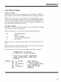
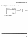
Assembly Language
Hex address 37E8 is memory mapped to the Line Printer Card-Edge
and serves as an input/output port.
Before sending a byte to this port, check enabled status bits:
bit
7
6
5
4
if set then status is ...
BUSY
OUT OF PAPER
DEVICE NOT SELECTED
NO FAULT
Note: Check your Line Printer Manual to see which status bits are
used.
When the Printer is READY, store the byte (an ASCII code for the
desired character) in hex address 37E8.
For example, if the ASCII coded character is stored in register C:
SUBROUTINE TO OUTPUT
A BYTE TO A LINE PRINTER
LOAD ASCII-CODED CHARACTER
INTO C-REGISTER, THEN CALL
PRTDVR
PRTDVR
LD A, (37E8H)
BIT 7,A
JP NZ ,PRTDVR
LD A,C
(37E8H) ,A
LD
RET
CHK STATUS
BUSY BIT SET?
LOOP WHILE BUSY
GET CHARACTER
SEND IT TO LP
RETURN
15
PERIPHERALS
Mini Disk(s)
Connect one 26-1160 Mini Disk Drive and up to three additional
26-1161 Mini Disk Drives, as explained in the Mini-Disk Operation
Manual. The connection cable is supplied with 26-1160.
Attach one of the flat connector hoods to the Mini-Disk connector
before attaching it to the Expansion Interface Card Edge. The ribbon
cable should exit from the bottom of the hood.
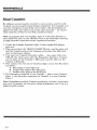
Bus Compatible Devices
This card-edge provides required signals for additional Radio Shack
peripherals. Any device that connects directly to the TRS-80 can also
be connected here, with the exception of the Screen Printer (Catalog
Number 26-1151). By using this Card-Edge, you don't tie up the
entire TRS-80 Interface with a single device.
For example, you can connect the Radio Shack Voice Synthesizer
(Catalog Number 26-1180) to the Expansion Interface via this CardEdge.
Expansion Board
The Expansion Interface contains a special Expansion Board
Compartment to allow installation of another optional printed
circuit board to expand your system's capabilities.
For example, you can have the Radio Shack RS-232C Serial Interface
(Catalog Number 26-1145) installed in this compartment. This will
enable your TRS-80 to communicate with another RS-232C device
(Telephone Interface, Serial Line Printer, etc.).
If you have enough experience in digital electronics, you might even
design your own circuit and install it in this compartment.
When you have such a board installed, you can access it via the
Expansion Board Card-Edge.
16
PERIPHERALS
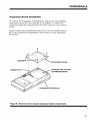
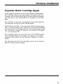
Expansion Board Installation
To expose the Expansion Compartment, remove the four phillipshead screws from the Cover and lift it off (Figure 9). Notice the
connector inside the compartment; this will connect to your add-on
board.
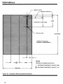
Figure 10 gives the required dimensions for a do-it-yourself board to
fit in the Expansion Compartment and connect to the Expansion
Connector.
~
..v HOUSING FOR FUTURE
~~
EXPANSION BOARD
EXPANSION INTERFACE
Figure 9. Remove cover to expose Expansion Board compartment.
17
PERIPHERALS
.188 DIA.(3/16)
CENTERLINE PIN 1
.165
.150
2.350
41 SPACES
@
.050=2.050
.125 DIA.(1/8)
6.375 MAX.
VIEWED FROM SIDE
OPPOSITE COMPONENTS
---..I
1.78~
.160
NOTES
2.900
UNLESS OTHERWISE SPECIFIED:
1. MAXIMUM COMPONENT HEIGHT .660
...- - - - - - 5.688 MAX. ---------J~
Figure 10. Expansion Board required dimensions.
18
B>MAXIMUM COMPONENT HEIGHT 1.10
TECHNICAL
INFORMATION
19
TECHNICAL INFORMATION
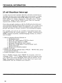
25 mS Heartbeat Interrupt
A clock circuit in the Expansion Interface provides an Interrupt to
the Z-80, 40 times each second. When such an Interrupt is received,
the Z-80 gets instructions from ROM telling it to go to a specific
RAM address for further instructions. Normally, these "further
instructions" simply tell the Z-80 to return from the interrupt
sequence and continue where it left off.
If you have enough experience with the Z-80 Instruction Set (and
with assembly-language programming in general), you can link up an
Interrupt Service Routine which accomplishes some simple foreground task before it returns control to the interrupted program.
For example, you can set up a real-time clock which keeps time
regardless of what the current program is - BASIC command mode,
BASIC program execution, machine-language routine, etc. Here's
how it's done:
1. Write an Interrupt Service Routine to
a. Disable Interrupts
b. Read FDC status register 37ECH to clear it
c. Read Interrupt Status in 37E0H
d. Increment the software clock counter
e. Read from 37E0H again to reset Interrupt Latch
f. Enable Interrupts
g. Return to interrupted program
2. Disable Interrupts
3. Replace the Interrupt Default link at 4012H - 4014H with a jump
to your Service Routine
4. Enable Interrupts to turn on the clock
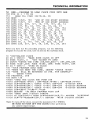
Here's a BASIC program which POKES the necessary code into
addresses 32680 - 32767. Note: Before using this program, reset
your TRS-80 and answer MEMORY SIZE with the number 32679.
Note: This program is for LEVEL II only. Don't try to use it with
DISK BASIC (use the TRSDOS clock instead!).
20
TECHNICAL INFORMATION
50
100
110
120
130
140
150
160
170
180
190
200
210
220
230
240
250
REM •.• PROGRAM TO LOAD CLOCK CODE INTO RAM
FOR I% = 1 TO 88
READ D%: POKE 32679+I%, D%
NEXT
POKE 16526, 168
'LSB OF ISR START ADDRESS
POKE 16527, 127
'MSB OF ISR START ADDRESS
DATA 243, 205, 127, 10, 175, 181, 40, 14
DATA 237, 86, 62, 195, 50, 18, 64, 33
DATA 193, 127,34, 19,64,251, 195, 154
DATA 10, 229, 245, 58, 224, 55, 203, 119
DATA 32, 49, 203, 127, 40, 38, 33, 94
DATA 64, 52, 126, 254, 40, 56, 29, 175
DATA 119, 35, 52, 126, 254, 60, 56, 20
DATA 175, 119, 35, 52, 126, 254, 60, 56
DATA 11, 175, 119, 35, 52, 126, 254, 24
DATA 56, 2, 175, 119, 58, 224, 55, 241
DATA 225, 251, 201, 58, 236, 55, 24, 244
After YOY have run the preceding program, run the following
program to execute the code, turn on and use the real-time clock.
10 'INITIALIZE CLOCK
20 CX = USR(O)
'MAKE SURE CLOCK IS OFF
30 POKE 16478, 0
'SET TICKER TO ZERO
40 INPUT "ENTER THE TIME (HR,MIN,SEC)"i CH%,CM%,CS%
50 POKE 16481,CH%: POKE 16480, CM%: POKE 16479, CS%
60 CX = USR(1)
'TURN ON CLOCK
100 'YOUR PROGRAM GOES HERE
110 'WHEN YOU WANT THE TIME, INSERT "GOSUB 10000"
120 'TIME WILL BE RETURNED IN CT$. FOR EXAMPLE-130
GOSUB 10000
140 PRINT@56, CT$
150 GOTO 130
10000 'READ THE CLOCK AND FORM CT$
10010 CH%=PEEK(16481): CM%=PEEK(16480): CS%=PEEK(16479)
10020 CC$=STR$(CH%): GOSUB 10100: CH$=CC$
'2-DIGIT HOUR
10030 CC$=STR$(CM%): GOSUB 10100: CM$=CC$
'2-DIGIT MINUTES
10040 CC$=STR$(CS%): GOSUB 10100: CS$=CC$
'2-DIGIT SECONDS
10050 CT$=CH$+":"+CM$+":"+CS$
10060 RETURN
'TO MAIN PROGRAM WITH CT$
10100 'MAKE INTO 2-DIGIT STRING
10110 IF LEN(CC$)=3 THEN CC$=RIGHT$(CC$,2): RETURN 'W/STRING
10120 CC$="0"+RIGHT$(CC$,1): RETURN
'WITH 2-DIGIT STRING
Note: To turn off the clock, execute the statement, CX = USR(O).
BE SURE TO TURN OFF THE CLOCK before performing
any cassette input/output.
21
TECHNICAL INFORMATION
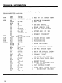
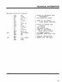
Assembly-language programmers can use the following listing to
relocate the real-time clock code.
ISR
USR
EXI
CLK
SEC
MIN
HOURS
22
ORG
7FA8H
EQU
7FC1H
; ENTRY VIA BASIC USR(N)
DI
CALL
OA7FH
XOR
A
OR
L
JR
Z,EXI
1M
1
LD
A,OC3H
LD
(4012H) ,A
LD
HL,ISR
LD
(4013H),HL
EI
JP
OA9AH
; REAL TIME CLOCK CODE
EQU
405EH
EQU
405FH
EQU
4060H
EQU
4061H
PUSH
HL
PUSH
AF
LD
A, (37EOH)
BIT
6,A
JR
NZ,FDC
BIT
7,A
JR
Z,XIT
LD
HL,CLK
(HL)
INC
LD
A, (HL)
CP
40
JR
C,XIT
XOR
A
LD
(HL) ,A
INC
HL
(HL)
INC
LD
A, (HL)
CP
60
JR
C,XIT
XOR
A
LD
(HL) ,A
SET TO ISR START ADDR
DISABLE INTERRUPT
GET (HL)
IS USR ARG=O?
IF YES THEN EXIT
ELSE LINK TO ISR
PUT IN JUMP TO ISR
START ADDR OF ISR
ENABLE INTERRUPT
TICKS STORED HERE
SECONDS HERE
MINUTES HERE
SAVE REGISTERS
GET INTERRUPT STATUS
IF FDC MAKING RQST
EXIT IF INVALID INTRPT
HL => TICKS COUNTER
UPDATE "TICK"
40 TICKS PER SECOND
IF NO CARRY INTO SECS
RESET TIKCNT
POINT TO SECONDS-COUNT
AND UPDATE
GET SECONDS COUNT
DONE IF NO CARRY TO HRS
ELSE RESET SECONDS
TECHNICAL INFORMATION
(Real-Time Clock Code, continued)
XIT
FDC
INC
INC
LD
CP
JR
XOR
LD
INC
INC
LD
CP
JR
XOR
LD
LD
HL
(HL)
A, (IlL)
POINT TO MINUTES AND
INCREMENT
; GET MINUTES COUNT
60
C,XIT
A
(HL) ,A
HL
(HL)
A, (HL)
24
C,XIT
~HL)
A
A,(3~EOH)
p8p
ilE
MT
A, (37ECH)
~~D
OS~
DONE IF NO CARRY
ELSE RESET MINUTES
POINT TO HOURS AND
UPDATE
GET HOURS
24-HOUR CLOCK
DONE IF NO CARRY
ELSE RESET HOURS
TO RESET LATCH
RESTORE REGS AND EXIT
ENABLE INTERRUPTS
RESET FDC IRQ RQST
23
TECHNICAL INFORMATION
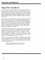
Floppy Disk Controller IC
The Floppy Disk Controller (FDC) in the Expansion Interface
directly controls the drive motors; track stepping and direction; write
gating and data. It also inputs information on the diskette index
position, track zero occurrence, write protection and data/clocking all at the Mini Disk Card-Edge on the Expansion Interface. The FDC
registers (CMD/STATUS, TRACK, SECTOR, DATA) are located at
TRS-80 memory addresses 37ECH, 37EDH, 37EEH and 37EFH,
respectively.
Drive selection is through Z47. Only one drive is selected at a time. A
time-Qut timer circuit (Z33) is activated/reactivated each time a
drive is selected/reselected, thereby protecting the disk drives in the
instance of program "crashes", as the drives are not designed for
continuous motor-on use. After two or three seconds, the MOTOR
ON line (15, pin 16) will deactivate (go high) unless Z33 is retriggered by a drive selection/reselection. Pin 6 of gate Z46 provides a
signal to the FDC (pins 23 and 32) when a head load has been
commanded (FDC status = READY).
TRSDOS programming takes into account that the Disk drive motor
requires one second to come up to operating speed, and that head
loading takes 80 milliseconds to stabilize. At the end of an FDC
operation, an interrupt is generated (pin 39 of FDC goes high)
which, through gate Z34 (pins 11 and 10), sets Z28, pin 9. This
interrupt request is terminated by reading the FDC status register
(address 37ECH) - which makes pin 39 of the FDC go low - then
reading from 37E0H, which resets pin 9 of Z28.
Because of the complexity of floppy disk operation, Radio Shack
does not encourage customers to bypass the TRS-80 Disk Operating
System for disk I/O, nor can we answer customer questions in this
area. Customers who are intent on such applications should start by
reading these publications:
• Shugart SA400 OEM and Service Manuals
• Western Digital FD 177lB-O 1 Data Sheet
24
TECHNICAL INFORMATION
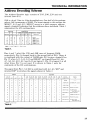
Address Decoding Scheme
The Address Decoder logic consists of Z43, Z40, Z39 and one
inverter from Z32.
Z40 is a dual 2-line to 4-line demultiplexer. One half of this package
selects 16K increments of RAM. The input signals to this section are
MRAS*, Al4 and AIS. MRAS* serves as a valid memory address
signal; a logical f/J indicates that the addresses have stabilized. Table 1
summarizes the I/O combinations.
INPUTS
OUTPUTS
Z40 Z40 Z40 Z40 Address Range
Pin 4 Pin 5 Pin 6 Pin 7
Selected
MRAS' A15 A14
1
\1
0
0
0
X
0
0
1
1
X
0
1
0
1
1
0
1
1
1
Note: In the Table, X
~
1
1
0
1
1
1
1
1
0
1
None
0000-3FFF
4000-7FFF
8000-BFFF
C000FFFF
1
1
1
1
0
Don't care.
Table 1.
Pins 6 and 7 select the 32K and 48K rows of dynamic RAM,
respectively. Pin 4 is looped back to the second half of Z40. There, it
is combined with the output of NAND gate Z43 to give a logical 0 on
Pin 12 when All, A14, AIS and MRAS* are logical 0 and AS, A6,
A7, A8, A9, Al 0, A 12 and A 13 are logical 1. Pin 12 is logical 1 at all
other times. Pin S is not used. It is shown in Table 1 only for
continuity of the I/O combinations.
The signal from Pin 12 of Z40 is combined with A2, A3, WR * and
inverted RD* to produce the signals shown in Table 2.
INPUT
OUTPUT
240
PIN 12
RD'
WR"
A3
A2
239
PIN 7
239
PIN 6
239
PIN 5
239
PIN 4
239
PIN 9
239
PIN 10
239
PIN 11
239
PIN 12
SIGNAL
GENERATED
SIGNAL
TO
-
1
X
X
X
X
1
1
1
1
1
1
1
1
NONE
0
0
1
0
0
0
1
1
1
1
1
1
1
37E0 READ
0
0
1
0
1
1
0
1
1
1
1
1
1
37E4 READ
0
0
1
1
0
1
1
0
1
1
1
1
1
37E8 READ
PRINTER LOGIC
0
0
1
1
1
1
1
1
0
1
1
1
1
37EC READ
0
1
0
0
0
1
1
1
1
0
1
1
1
37E0 WRITE
FLOPPY DISK
CONTROLLER
DRIVE SELECT
0
1
0
0
1
1
1
1
1
1
0
1
1
CSW
CASSETTE RELAY
0
1
0
1
0
1
1
1
1
1
1
0
1
37E8 WRITE
PRINTER LOGIC
0
1
0
1
1
1
1
1
1
1
1
1
0
37EC WRITE
FLOPPY DISK
CONTROLLER
NOTE: X
=
INTERRUPT LOGIC
-
Don't Care
Table 2.
25
TECHNICAL INFORMATION
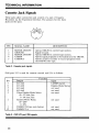
Cassette Jack Signals
These jacks allow connection and control of a pair of Cassette
Recorders via the Expansion Interface. The pinouts for the three
jacks are the same.
4
2
'~'
PIN
1
2
3
4
5
SIGNAL NAME
MOTOR ON/OFF
GROUND
MOTOR ON/OFF
CASSIN
CASSOUT
DESCRIPTION
Allows TRS-80 to control tape motion.
Signal Ground.
Allows TRS-80 to control tape motion.
Allows taped programs to be loaded into the TRS-80.
Allows cassette recorder to record programs from
the IRS-80 onto tape.
Table 3. Cassette jack signals.
Z-80 port 255 is used for cassette control and I/O, as follows:
Bit
7
6
5
4
3
2
1
0
Function
Output
not used
not used
not used
not used
Video Display Mode Select
f/J = 32 char./line
1 = 64 char./line
Cassette Motor Relay
f/J = OFF
1 = ON
CASSOUT B (see note below)
CASSOUT A
Table 4. Z-80 I/O port 255 signals.
26
Input
CASSIN Latch
Display Mode Status
not used
not used
not used
not used
not used
not used
TECHNICAL INFORMATION
Note: CASSOUT A and B are both used to produce the cassette
audio signal, as follows:
CASSOUT
A
B
Audio Pulse
High
0
0
No Signal
I
I
Pulse Low
0
I
Pulse Low
I
0
Pulse High
O.85V
No Signal
0,46V
Low
O.OV
Table 5. How CASSOUT A and B produce the three-state cassette
audio (High, Low, No Signal).
27
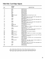
Line Printer Card-Edge Signals
SIGNAL
NAME
PIN
DESCRIPTION
DATA STROBE*
2
GND
3
4
5
Dl
GND
D2
GND
D3
GND
D4
GND
D5
GND
DB
GND
6
7
8
9
10
11
12
13
14
15
16
17
18
A 1.0 microsecond pulse used to clock the data from the
processor to the printer logic.
Signal Ground
Input data levels. A high represents a binary one, a low
represents a zero. All printable characters (i.e., codes
having a one in DATA 6 or DATA 7) are stored in the
printer buffer. Control characters (i.e., codes having a
zero in both DATA 6 and DATA 7) are used to specify
special control functions. These codes are not stored in
D7
the buffer except when they specify a print command
GND
D8
GND
and are preceded by at least one printable character in
that line.
19
NC
GND
BUSY
GND
OUT OF PAPER PE
GND
UNIT SELECT SLCT
PRIME*
20
21
22
23
24
25
26
27
Not Connected
Signal Ground
A level indicating that the printer cannot receive data.
Signal Ground
A level indicating that the printer is out of paper.
Signal Ground
A level indicating that the printer is selected.
A level which clears the printer buffer and initializes
the logic.
Signal Ground
A level that indicates a printer fault condition such as
paper empty, light detect or a deselect condition.
Not Connected
Not Connected
Signal Ground
Not Connected
Signal Ground
Signal Ground
GND
FAULT*
28
29
NC
NC
GND
NC
GND
GND
30
31
32
33
34
NOTE: All GND signals are common.
33
31
29
27
25
23
21
19
17
15
13
11
9
7
5
3
1
34
32
30
28
26
24
22
20
18
16
14
12
10
8
6
4
2
:: :: :: :: :: :: :: :: :: : : : : : :: :1
28
Mini Disk Card-Edge Signals
SIGNAL
NAME
PIN
DESCRIPTION
Signal Ground
Not Connected
Signal Ground
Not Connected
Signal Ground
Not Connected
Signal Ground
Indicates the physical beginn ing of a track.
Signal Ground
When active, locks the mini-disk RIW head against the
mini-diskette (disk drive no. 0).
Signal Ground
When active, locks the mini-disk RIW head against the
mini-diskette (disk drive no. 1).
Signal Ground
When active, locks the mini-disk RIW head against the
mini-diskette (disk drive no. 2).
Signal Ground
Turns ON all drive motors.
Signal Ground
Defines direction of motion the RIW head will take
when the STEP line is pulsed.
Signal Ground
Causes the R/W head to move with the direction of
motion as defined by DIRECTION SEL.
Signal Ground
Provides data to be written on diskette.
Signal Ground
Enables WRITE DATA to be written on the diskette.
Signal Ground
A logical zero state indicates that the drive's RIW head
is positioned at track zero.
Signal Ground
Gives the user an indication that a write protected diskette is installed.
Signal Ground
Provides the "raw data" (clock and data together) as
detected by the drive electronics.
Signal Ground
When active, locks the mini-disk RIW head against the
m in i-diskette (disk drive no. 3l.
Signal Ground
Not Connected
GND
NC
GND
NC
GND
NC
GND
INDEX PULSE*
GND
DS0*
1
2
3
4
5
6
7
8
9
10
GND
DS1 *
11
12
13
GND
DS2*
14
15
18
GND
MOTOR ON
GND
DIRECTION SEL *
19
20
GND
STEP*
21
24
25
26
GND
WRITE DATA*
GND
WRITE GATE*
GND
TRACK ZERO*
27
28
GND
WRITE PROTECT*
29
30
GND
READ DATA*
31
32
GND
DS3*
33
GND
NC
16
17
22
23
34
33
31
29
27
25
23
21
19
17
15
13
11
9
7
5
3
1
34
32
30
28
26
24
22
20
18
16
14
12
10
8
6
4
2
I: ;: : : : : : : :: : : : : : :: :1
29
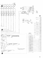
Bus Card-Edge Signals
This card edge duplicates the card edge on the TRS-80 Computer.
SIGNAL
NAME
PIN
RAS*
SYSRES*
1
2
3
4
5
6
7
8
9
NC
A10
A12
A13
A15
GND
All
A14
A8
OUT*
WR*
INTAK*
RD*
NC
A9
D4
IN*
D7
INT*
Dl
TEST*
10
11
12
13
14
15
16
17
18
19
20
21
22
23
24
25
26
27
28
29
30
31
32
D6
A0
D3
Al
D5
GND
D0
A4
D2
WAIT*
A3
A5
A7
GND
A6
+5V
A2
33
34
35
36
37
38
39
40
NOTE:
DESCRIPTION
Row Address Strobe Output for 16-Pin Dynamic Rams.
System Reset Output, Low During Power Up Initialize or
Reset Depressed.
No Connection
Address Output
Address Output
Address Output
Address Output
Signal Ground
Address Output
Address Output
Address Output
Peripheral Write Strobe Output.
Memory Write Strobe Output.
Interrupt Acknowledge Output.
Memory Read Strobe Output.
No Connection
Address Output
Bidirectional Data Bus.
Peripheral Read Strobe Output.
Bidirectional Data Bus.
Interrupt Input (Maskable).
Bidirectional Data Bus.
A Logic "0" on TEST* Input Tri-States A0 - A 15, D0 - D 7,
WR*, RD*, IN*, OUT*, RAS*, CAS*, MUX*.
Bidirectional Data Bus.
Address Output
Bidirectional Data Bus.
Address Output
Bidirectional Data Bus.
Signal Ground
Bidirectional Data Bus.
Address Bus
Bidirectional Data Bus.
Processor Wait Input, to Allow for Slow Memory.
Address Output
Address Output
Address Output
Signal Ground
Address Output
5-Volt Output (Limited Current)
Address Output
* means Negative (Logical "0") True Input or Output.
1
3
5
7
9
11 13 15 17 19 21 23 25 27 29 31 33 35 37 39
'222 2 2 2 2 ;:; ::; g ::; ;:;
2
30
4
6
8
z ::; z z z ::; ;:;
2:
10 12 14 16 18 20 22 24 26 28 30 32 34 36 38 40
TECHNICAL INFORMATION
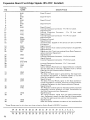
Expansion Board Card-Edge Signals
If you install an expansion board in the Expansion Compartment,
this Card-Edge will give you easy access to the added board. For
example, with the Radio Shack RS-232C Serial Interface installed,
you will connect your external RS-232C equipment to this CardEdge.
The Card-Edge is connected to the Connector inside the Expansion
Compartment, and also to certain TRS-80 signals:
TRS-80 Data Lines (D0 - D7); some of the TRS-80 Address Lines
(A0 - A2); the I/O strobes (IN* and OUT*); the reset line SYSRES*;
+5 volts; ground; the interrupt line INT* and a decoded signal called
E8*. E8* goes to a logical "0" when-A3, AS, A6 and A7 are logical •
"1" and A4 is logical "0".
The Card-Edge itself is not connected to any of the TRS-80 signals.
Your Expansion Board must supply any signals your external
equipment will require. See the Schematic Diagram for further
details.
The following table shows the Card-Edge pinouts with the optional
RS-232C Interface board installed.
31
Expansion Board Card-Edge Signals (RS-232C Installed)
*SIGNAL
NAME
PIN
DEseR IPTION
Signal Ground
GND
NC
GND
NC
GND
NC
GND
NC
GND
1
2
3
4
5
6
7
8
9
Signal Ground
Signal Ground
Signal Ground
Signal Ground
Internal Expansion Connector - Pin 16 (not used).
Signal Ground
I nternal Expansion Connector
Pin 15 (not used).
Signal Ground
Internal Expansion Connector - Pin 14 (not used).
Signal Ground
Protective Ground
Signal Ground
Transmit Data - Signals on this Circuit are sent to remote
Equipment.
Signal Ground
Signal Ground from Data Communications Equipment.
Signal Ground
Signals on this Circuit are received from Data Communications (remote) Equipment.
Signal Ground
Internal Expansion Connector - Pin 9 (not used).
Signal Ground
I nternal Expansion Connector - Pin 8 (not used).
10
11
12
GND
13
14
15
16
GND
GND
PGND
GND
TD
17
18
22
GND
SGND
GND
RD
23
GND
19
20
21
24
25
26
27
GND
SIG GND
28
29
30
GND
CD
31
32
GND
CTS
33
GND
DTR
34
35
I nternal Expansion Connector - Pin 7 (not used).
Signal Ground
Carrier Detect (Received Line Signal Detector) indicates
that the Data Set is receiving a character from a remote
Data Set via the Communications Channel.
Signal Ground
The Clear to Send signal is generated by the Data Communications Equipment. It indicates whether or not the
Data Set (modem) is ready to transmit Data.
Signal Ground
The Data Terminal Ready signal to the Data Communications Equipment controls switching of Data Communications Equipment to the Communications Channel.
Signal Ground
The Request to Send signal to the Data Communications
Equipment controls direction of Data Transmission by
the Data Communications Equipment.
Signal Ground
The Ring Indicator signal from the Data Communications Equipment means that the Data Set is being polled
and that the polling service wants to communicate.
Signal Ground
Data Set Ready indicates the status of the local Data Set.
GND
RTS
36
37
38
GND
RI
39
40
GND
DSR
* Signal Names used in this chart are those related to Radio Shack's RS-232-C Interface.
39
32
37
35
33
31
29
27
25
23
::: ::: ::: ::: ::: ::
::
::::
::
40
28
26
24
38
36
34
32
30
21
19
17
::::
:::
22
20
18
16
:: ::
15
13
11
9
7
5
3
1
14
12
10
8
6
4
2
:: :::::::::::::
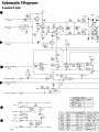
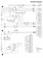
Schematic Diagrams
Control Logic
•
-+ 121/ A,
2A
L.\
1.•.'2.
c.eo
TPI
84S
•
1/81.0
\'='0
C1Z.\O
1"/0
4
-------<~I
~ """I
X~4o\
~
I2/W
'28
q.
R~+I2.V'"
84'5
I/BW
I
10/0
TC~o
,W
121
2.01(
R/W
....r;v
e.l2.~
'2.--------------<~-4----......_'4_I
1<41-
R~
)('0.:10\
'2.K
9.0'::lK
\/8W
\ 0/0 .........._--<lI--_~ +-12'1A.
+5'>/
12.\4
ZOI(
+5'1
Rza
"300
+5'1
~
J)
4~
.:£~.j
+ VJlGI'p= PI:20\.-----1iy.>DL----<l....-.
-{-IiJ:F'~_"2.~~~_:. . -
f~
'l.c..
~ l P9
+'='V-R
'I.'2.!\'OK
I'li'7'_-
1
-..jr-~:..:::-2....)L::/.:=
>""8--t
!t-+-oWjPWI c U A . e > L I : - - - - - - - - - - - - - - - - - - - - - - - + - - - - - - - - -
_
~ T : lI::~
)("540\
R~Z
lOOK
+5\,1
- If-JDE,>£: / 'OEC..1012 - - - - w ' - = E : ' - - - - - - - - - -
Z~
3
.D"
4
_
-=
ZoE
-------------------------
123\
5.D"
(.,
411<
R&"=>\~T01'
V~LWE:"=,~n.
'---4I:tr-+I'ZV
{
-+ 12V IZ1 1'-1
--\3,1-l-=~-
----------+IZV
_---I
-..l\(jJ-!.2.=--_-+_'-
",eon.
...
~,"f4~)
TYPE
Pes.
l400
SE.
140Z
se:;
2.10
74-LS 14-
-+ 5\,1 12, tJ
4- - -
-+sy -W.:.
2-11
------+sv
RPI
RP'::>
\'=>On.
110<.
' - - . - - - - - + 12VI>.
140"1
U.4D
""1433
,438
'<!D
21=
1414
ze,ID
l-4-\95
:!>D
!>C
14L<::>2'21
Uf.lLl~ED
IDle.
A.i<12A.'f'
i=O""'T\ON ur-JU""E:-D
R.P'2: ~ '0
121"4
·'{f.cr)
~o
IU
1414
.,
1414
1
1
1
1
14
14
\4
1
I
1"-
8
ltD
8
~S\
-
T,<P6
1'=>45313
LM311lJ
3F
4bo.
\oI=<;''1'Zl>.
3A.
,48b
4c.
9"oZ
ZG.i'Z2'2'2
-
'l.Gl.,-'ZqO'b
-
MF'l'Jl~I'2.?
-
Po~. U\.ILl
\ 'Oo..n.
4C.~
4B
'2 A.
Ie.
IE
~
\
-+5'/
gZ9
510
+ PUl.l.
uP '2.
>££0401
+
PULL UP
)(S40\
+5\1
f2.\S
101(
~o
W01&~'
I.
2.
5.
4.
s.
Co.
+5V~
12~
=e
\/'l.W
T,<Pe<
Po'::>.
1'::>4'538
5F
4,1,.
_M3\ \ IJ
.le:...qt","
148("
9"'°2
3A.
4c.
'ZA.
>l-i'<~qO'b
IC
F'G~1'2";
IE
4-i=
1,~pT5"\
B
4<:.2
46
~i'l'Z'Z'Z
"O.n.
Ul:lu~l:l
-
4
I
B
5
10
14
1
ICo
B
-
-
-
'L
~~~ y,~'-J~
-
-
8
'SPeCI!=I~D,
I:>.LL C-A.P~clJo"e;,
ARt:
11-.\ U\1C.12.0Ft>.\2..I>.O~) 5D\I, +80, -- 20<>/".
ALL DIODE'S .:>.\2.... 1~414B.
t.LL \ 'lDUC.TOR~ 1:>. ...... It-.l I-\ICJ<OHE~RIE.S) \0 0 10.
I>.LL R=,""\~'-"ORe;, I:>. ...E:. It-.l o\.\\-I'S).
rJ4W) SOlo.
0--0 II..lOlc..l>.\c,,:> Sl-lLlfJT SE:Lt:GTAf:l.....
OPT\O\oJ.
*1~OIC.I:>.\E~ j\(W-\\..lOICI:>..\tOS.J'Z)
--w-
\f..lDIC-I>.iE":>
.:l~)-W-lt...ID\c.t>.le"::> j4.
CO,,",POt--lE.N' t...IOT
\ fJ'STA.l-L.E.D.
PII'-l 4 01= 10 1'0 Gl\<oUt-.1D.
C:31
C \2..1 9
\...5
Q'Z
\2..42
lC!P5
TPI~
--
- - -
-
[J]
UIJ\..ES":> 0T\4E-RWI"::>E
-
2-12
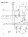
Read/Write Logic
1\
12- 10 ., Ib
[[
IE
4
<0 5
~e::.
"'.
0
1
1P1O
5
~
I
ZC
II~\O
.....
I'll
~
2.2<;0"
OR 01-1
'/8W
0
\6
+PULL uP '2.
"')('<.400
-WRITE.
DAiA
22
\~ IT 12
5
Co
IeEl
fl~~
Q "
13~1'l
+12.'./
sv
tD
I
-WRitE G\
=-
~\
"'-
24
8~
9:J1ZDJ 'o
PR0"\"
-x.~400
-DRIVE. '::>E:L.E:Ci
\
10
1-
~"
I~
t:F..1
it
T?
12
"::'
4
f?
SE:Lt=CT
3
4
'-J
DIR,ECTloo-J
Go
'2.
;2-
I
\2~3B'13
IT
12~
I~
e
~e:
9
1
"*
II
'-'
'20
I
~
50
"tl5o
-5 i"P
-t!
1&
-
~I\
9
10 3E
B
~
p,
Ie,
11_1':>...10
16K
CI'2.
1.0
0
10 /0
,1
it
4.1~
+Sy Gil
.1
0
10 /0",
''So
-
Gl
~
\0
1"
-=-
B
-913B>4'
G~
eo
I
-+5\1
7
'r A:CQLJ rA?:a
~e.
PUL.L. uP I
)(.54.00
~G
RZ,
RZS
+
I
c121,
tl":'z..
\4
Q'Z
CRB'
11=
- DRIVE
~
2fJ2z'Z'Z
~
"-
~I
12
b
~
IZ~
10
tv\'l4
'"
0
1 /0
,.-----<
~
RP,
QIG:>
R.\
>
4
'Z.
~
zE
of
+ WRIT
/0
1
R~"O
C~\
"750p+'
~v
=:'0/0
"000
..L
1
+5\1
I
So
I
- TR/>.C.K 'eERo
fJ. o.
+ 'RI>.CK
~E-RO
w.e::..
2-13
RP,=>
1
1<'30 *C'2.9
\00
-'-
"::'
elP8
Q]
-br '2
->;?rF-------:"'=+---t..!:&~---------------...L1
cl3E. >-:.O<""
...:!..1
I-l
[
KW- -
C.RGo
2
\
\--ITR. OW
R/W I
R\9
ZoK
Ie.
\(~4oo
"::"
4
:3
z.
12
Ie
CR5
14-
R/\AJ
RW
I2P3
<004
0;:,
I/aw
/0
1
RIB
I~
0
+ sy'
20K
RZ3
't[tw
I 1
0
16
\~~'N
10
Ie.
R:z'Z
2."14:w
\ JB
0
:>0::'5400
Rz4
":"
1
'Z.
c.R9
I:.R!>.SE.
10
12'2.\
,,"0 K
"::"
iC/v..i
~'Z2'2'2
~4
1':>0
-
"::"
~
'-T.
)C'540o
Zc. 4
.lr51J
boG jIV1'T'1'
1-1:0
A,c..T1V1i'f'
\...&-0
~
+12V
"l
'='
~\~
4-SV
-
J..\E:,b..O \...01>.0
+
REO-A.D
+
OLlTPI..I1 E-f..lAe>L....
"'54 0
=-~A.e.L='X~40o
+I,V
cPD
epC-
epB
1----'-E----!~~C.1213c121Z c.12\\
----4----~-*__1lH._-+SV
26
cPA
z
-i"Rl>.C-K
~E-RO
":"
2-14
r
TRS-eo BUS
J2
~
'29'
e
~J3"'"
UD
WAIT_
L.1L
''---=-=-I
5V
---.)oJ3<D
TEST. ------. J3.23
DO
CJIJ
J3-29
1
1
i~
,~
_ 37E8 READ
~
D7
"~"
J,3-37
D6
J3-B
D5
D'
D3
D2
GNO
D'
DO
37EOWRITE
nn
D7
I~
4
5
•
D'
7
D4
OD-
~
15
I.
~
14
13
••
D5
I28l
37EB
'.
1
"
"
12
"
"
18
17
2
3
"
-"
Z51-74LS240
ioe
D,
LE
~
••
D2
~
."'}
L--.....+Z31-5
rT~~~'
C4"
~Z313
TO
SHT
2
R2
,K
13
RI6
12~t1
404••
AIN
H
2
... '
INT4K_
J3-12
~
....
!:lC
.CEJ
'
;~
34
,..
15
A'
17
A.
••
8
41
~U5-5}
AS Z.H-5
5
'<-<
"--<
,..:-. 0:
,~U
',.--.
,~
7
Ir-y-'
r,
A3
All
Z45
•
11
•
2
7
5
8
,.
Z44
74LS244
Z43
-----.
74LS24.4
,.
•
R,,_
I•
TO
2V3
6'
<28
OK
10
19
llll
4
RE
'0
37E; READ
31£8 READ
7Ee READ
37E 0 WRITE
37E 4 WRITE
37£ B WRITE
'WI'
12
~
5
•
~
ttl
5
7
4
2
A"
1Y2 '..
IV>
9
2YO
10
239
2Y~
'1
74LSI55 2Y2
a2
12
7
3
Ale
7
A
A
,.
•
,
III
lV' fL-;NC
~Z'H
A
l8
CLOCK
AO
A'
3
13
I
~
'V,
••
~~.11 ~T.
1
, _ Ii1 I..
el
15 C2
..z
2
A5
35
,.
,
~
13
,
•
•
I
t.~
52 T
,r::I.
10
74t6
I
Z35"14
232 74LSIl4
•
,
..
n.
125
Z35"ll} W
~Z36.2
~Z35-2
4------------
~~l.S243-Z30
~
13
.2
A3
2 T
4
.2
FI
2
12
,
RO •
e
Ne
'0
24
SYSRES_
[JC
'",,-
nfeKPRE Q •
flc
.I~T*
,:r:::
•
r~
J3-19
ZV·4
,L-iL
1
Z2.
741..574
741574
2321} ~
r=-1
7~'
Z25
J3-14
------'INC
INO
Ir-z;o
IN TRQ
~~~
NC
OUT.
t
T0
s:
~ a... ~
ri~... ~
~ . . E.2~
R2 ENZW
,
'-i"i..04 '
~6
~
nrl
'0'
12
".--.;I"----'."""~--JI-.~ ~
OD
Z22
74LS91
04 2
I'-=-'
RJO
Z"1" LUI7
U"
R3
2,U:
~5
L::-J
1'l6'
19
DiL0
'5
,41
c::E:
,
7
242
FDH7tB
R£AD
,.
r
11
RI
o:::J
"37EC
wR.
,OM
IL-!C
,
DAL1
13
250-74LS240
229-7
Z 29-5
Z293
C43
~,.~
0AL2
8
f----'"
L-+ 231-7
~Z2"
9
11
.~
7
,
,8
17
"~
,
I
15
~
3
DO
10 DAL3
,.
4
5
D3
[KJ
12
A8
".
4
••
. ~G2
~S3111
14 AZ
2Y1
ZYl
ITO
, Y'
3
13
2
~m.,'
82
Al
.,
t
a
~Z3510
}TO
AI0 Z3~,3
~HT
~136-6
'1"
no ,,!L
2>3
A'
All
A1<
1
Z4.
!y2
!Y3
~Ne
~
~NC
•
7
e5w
32<
'.K
232-3
Z27-2
Z27-13
74LS139
,
,
9HT
)
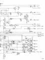
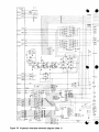
Figure 13. Expansion Interface schematic diagram (sheet 1)
.----J
29
NC~
17
NC
20
Ne
J
s---J
) TO
SHT
2
F
MRA5*
RAS*
Z36-1"}TO
136-3
10
• ",
2
Voo
Vo<
VB"
38 ORO
~-5V
~NC
P'-HC
ZV
5V
-tI-
3
TG43
PH3
vss
cs
-
0116-12
~
--=J l'
_24"13
•, .,••
.2
Z0ll5-1
Z4~ Z4~ 14~ - 5
=45 - 1
144-1
144-1
Z44 -
, ••
2 ••
,
'1
'2
n5
14
I~R26
74LSI~7
•
.,"
~5fJ,l.l
...
r::-::-:I
2-'
5
11
• .,
.2
...-;
A4
Zi
11
~lol'"''
10
"
.,0
r
~'S
,-
128·1213
r--+--~Z46-1Q
~
Z45-14
Z4~
j I r~z",
A5
NCr-------------2J
Z36
Z
~---~
74LSI57
144 - 7
Z4011
5
~-~~
AI2
6
9
I
~
1
~
R27
10
SHT
,
A1
A.2.
:;
19
A~MM116
Z«
,.1<4
A6
WR
I~L_
n
~
~R18
'----
~
r----J
1~-,6'----<>-t+H'--~~+ ---.-----
13 IV
12 LU.z
11
l~3
M32_
''-.'r -::-I
---I,,-21
K
---
M48=••+-H~"'i~----------
1~R'l9
--'~3--1.~~ 19~
-+'=-
1
33
~-=.--4-t-II-t~""-t----
.MRAS.
~---.
~,.
"5
J1S
~:lJX
11374~.111~'10
138 - 9
1 __ --
1-c1'-------+~_t__, I
'----------=
NC>-~
232
+rr--:===~§~~~~~~~~t~~==§~I"
~,_
5
~--l-~
-12
Z45-16
144-16
--=
Z3~04 +-
1Z9-74LSZ44
I
14
139 - 10 ~-----------
L
•
'2
-
I
------------1
+61
I
I
---------------
'f'5'o' UNAlOULAn:o
-l
+CCb
/
'0
16
I~ :=L:
w:-
I
'o'C
221
I
mc
I
I
I
I
I
+
0'
(
T12'o' UNREWLATED
-'V UNREGULATED
+ C55
2200
35v
1
I
I
I
L_
.;l
R4
I ZK
t
E2955
V c '0'0
R35
,W
56
R'
10
C,
~F
1.C~
I
AS
2,21<
"
RIO
'"
I
I
I
I
L_
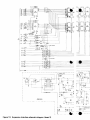
Figure 13. Expansion Interface schematic diagram (sheet 2)
--e----
TRS 80
CASSETIE
SOC!'l£T
p,"
1 EN
DO
2 GROUND
, EN
" CASSIN
~
CASSOUT
INTERNAL
EXPANSION
PlH-OJT
(G~-- ~
~
A7
'02J- -~.-m
.~
l35-3
A6~~------'~
36-S
3
'46
74LS20
~~2
Z417416
NC
~
NC
OD
_ _ _ _ _~E'.".C'.'--_ _--Ic:::J:]U
~1
13 Z28
74lS00
G::)~
~ ~-
- -------c=rEJ
Ci~~
-
C~--
---c:.:I.RJ
~
~_
...
~
GQ-c:=::rr:J
~
~
G0--~
G0--c=:I:ill
~
~
EXPANSION
BOARD CONNECTOR
-I
I
I
I
c;c)-- ---c::::Iill
JI
C~~
NC
L'LJ--==-+---+ -------------'\ He
NC
~
NC
OD
He
[I[]
}----=-+--+--
---<
NC
f-C---=:::::..-+---+-------;
NC
I
--------L---=riO
I
+
12
v
-r-~l--~
~~"
11(
R7
1~"-~~6
16'
.
C9,C",CI5,Cll,C2~1
TO~O~2.C34.C38.C40
18Y
T C,I
~~' C3 ',C31,C71
CI2,CI ••CIB,C20
-----l
LV
1. C.8
.7
J
331(
NOTES
~; Al~
RAMS (MI(4116) ARE IN 16 PIN SOCKETS
;IN 1,3,4,5,6.7,8,9,10,11,12,13 AND 16
Of ALL RAMS TIED IN PARALLEL
.J
~1,C3,C5.C7,C21
J~
H:.m,C27,C70
I
I
I
14
I
I
I
RIO
Rl,
'2K
~
-----iNC
C2,e4. Cei, C e, C22,
J
-~----
C24, C26,C28
COl
16V
I
I
I
I
I
I
I
----------c:::::
~
--
~------e:=r::::cJ
__J
41
LIMITED WARRANTY
For a period of 90 days from the date of delivery, Radio Shack warrants to the original purchaser that the computer hardware described
herein shall be free from defects in material and workmanship under
normal use and service. This warranty is only applicable to purchases
from Radio Shack company-owned retail outlets and through duly
authorized franchisees and dealers. The warranty shall be void if this
unit's case or cabinet is opened or if the unit is altered or modified.
During this period, if a defect should occur, the product must be returned to a Radio Shack store or dealer for repair, and proof of purchase must be presented. Purchaser's sole and exclusive remedy in the
event of defect is expressly limited to the correction of the defect by
adjustment, repair or replacement at Radio Shack's election and sole
expense, except there shall be no obligation to replace or repair items
which by their nature are expendable. No representation or other affirmation of fact, including, but not limited to, statements regarding
capacity, suitability for use, or performance of the equipment, shall
be or be deemed to be a warranty or representation by Radio Shack,
for any purpose, nor give rise to any liability or obligation of Radio
Shack whatsoever.
EXCEPT AS SPECIFICALLY PROVIDED IN THIS AGREEMENT,
THERE ARE NO OTHER WARRANTIES, EXPRESS OR IMPLIED,
INCLUDING, BUT NOT LIMITED TO, ANY IMPLIED WARRANTIES OF MERCHANTABILITY OR FITNESS FOR A PARTICULAR
PURPOSE AND IN NO EVENT SHALL RADIO SHACK BE LIABLE
FOR LOSS OF PROFITS OR BENEFITS, INDIRECT, SPECIAL,
CONSEQUENTIAL OR OTHER SIMILAR DAMAGES ARISING OUT
OF ANY BREACH OF THIS WARRANTY OR OTHERWISE.
RADIO SHACK
M
A DIVISION OF TANDY CORPORATION
U.S.A.: FORT WORTH, TEXAS 76102
CANADA: BARRIE, ONTARIO L4M 4W5
TANDY CORPORATION
AUSTRALIA
BElGIUM
U. K.
280·316 VICTORIA ROAD
RYDAlMERE, N.S.W. 2116
PARC INDUSTRIEl DE NANINNE
5140 NANINNE
BllSTON ROAD WEDNESBURY
WEST MIDLANDS WS10 7JN
874-9004
PRINTED IN U.S.A.