1
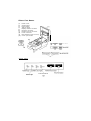
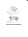
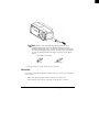
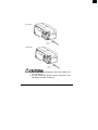
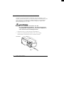
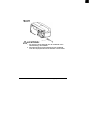
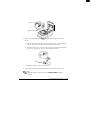
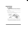
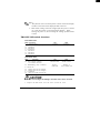
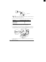
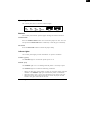
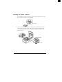
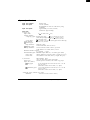
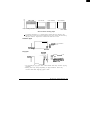
TM-U375
User’s Manual
400391307
Printer Part Names
Printer cover
Control panel
(3) Power switch
(4) Take-up spool
(5) Display module connector
(6) Interface connector
(7) Drawer kick-out connector
(8) Power connector
(9) DIP switches (under a cover)
(10) Cover open recess
(1)
(2)
Control Panel
VALIDATION/SLIP
All rights reserved. No part of this publication may be reproduced, stored in a retrieval
system, or transmitted in any form or by any means, mechanical, photocopying, recording,
or otherwise, without the prior written permission of Seiko Epson Corporation. No patent
liability is assumed with respect to the use of the information contained herein. While
every precaution has been taken in the preparation of this book, Seiko Epson Corporation
assumes no responsibility for errors or omissions. Neither is any liability assumed for
damages resulting from the use of the information contained herein.
Neither Seiko Epson Corporation nor its affiliates shall be liable to the purchaser of this
product or third parties for damages, losses, costs, or expenses incurred by purchaser or
third parties as a result of: accident, misuse, or abuse of this product or unauthorized
modifications, repairs, or alterations to this product, or (excluding the U.S.) failure to
strictly comply with Seiko Epson Corporation’s operating and maintenance instructions.
Seiko Epson Corporation shall not be liable against any damages or problems arising from
the use of any options or any consumable products other than those designated as Original
Epson Products or Epson Approved Products by Seiko Epson Corporation.
EPSON and ESC/POS are registered trademarks of Seiko Epson Corporation.
NOTICE:
The contents of this manual are subject to change without notice.
Copyright 0 1995, 1998 by Seiko Epson Corporation, Nagano, Japan.
i
EMC and Safety Standards Applied
Product Name: TM-U375/U375P
Model Name: M63UA/M115A
The following standards are applied only to the printers that are so
labeled. (EMC is tested using the EPSON power supply)
Europe:
CE Marking
Safety: EN60950
North America:
EMI: FCC/ICES-003 Class A
Safety: UL 1950/CSA C22.2 No. 950
Japan:
EMI:
Oceania:
EMC: AS/NZS 3548
VCCI Class A
WARNING
The connection of a non-shielded printer interface cable to this printer will invalidate
the EMC standards of this device.
You are cautioned that changes or modifications not expressly approved by SEIKO
EPSON Corporation could void your authority to operate the equipment.
ii
CE Marking
The printer conforms to the following Directives and Norms
Directive 89/336/EEC
EN 55022 Class B
EN 55024
IEC 61000-4-2
IEC 61000-4-3
IEC 61000-4-4
IEC 61000-4-5
IEC 61000-4-6
IEC 61000-4-11
Directive 90/384/EEC
EN45501
FCC Compliance Statement
For American Users
This equipment has been tested and found to comply with the limits for a Class A
digital device, pursuant to Part 15 of the FCC Rules. These limits are designed to
provide reasonable protection against harmful interference when the equipment is
operated in a commercial environment.
This equipment generates, uses, and can radiate radio frequency energy and, if not
installed and used in accordance with the instruction manual, may cause harmful
interference to radio communications. Operation of this equipment in a residential
area is likely to cause harmful interference, in which case the user will be required to
correct the interference at his own expense.
FOR CANADIAN USERS
This Class A digital apparatus complies with Canadian ICES-003.
Cet appareil numérique de la classe A est conforme à la norme NMB-003 du Canada.
iii
GEREÄUSCHPEGEL
Gemäß der Dritten Verordnung zum Gerätesicherheitsgesetz
(Maschinenlärminformations- Verordnung-3. GSGV) ist der arbeitsplatzbezogene
Geräusch-Emissionswert kleiner als 70 dB(A) (basierend auf ISO 7779).
iv
Introduction
Features
The TM-U375 and TM-U375P are high-performance POS printers which
handle slip, validation, and journal printing (both journal and receipt
printing with pressure-sensitive paper) in a single unit. The main features
of the TM-U375 and TM-U375P printers are as follows:
0 World’s smallest multi-function 1.5 station printer.
Ci High-speed printing using logic seeking.
0 Easy problem handling (e.g., paper jams or objects dropped into the
printer) via a clamshell mechanism.
a Two validation/slip paper entrances: from above for validation paper
and from the front for slip paper.
U Free-format printing in page mode.
Q Various check printing pattern.
Cl Logic seeking and page mode for check printing.
Ct Movable platen for easy paper insertion.
Cl Paper load switch for easy paper roll loading.
Cl Control capability for two drawers.
a Selectable character size (7 x 9 font or 5 x 9 font).
Q Command protocol based on the ESC/POS@ standard.
Q ASB (Automatic Status Back) function that automatically transmits
printer status changes.
Q EPSON ® intelligent module connection (for the TM-U375 only).
Cl EPSON display module series connection (for the TM-U375 only).
Ct Bidirectional parallel interface in accordance with the IEEE 1284
Nibbe/Byte Modes.
About This Manual
Setting up and Using
El Chapter 1 contains information on unpacking the printer, setting it up,
setting the DIP switches, and adjusting the paper near end detector.
CI Chapter 2 contains information on using the printer.
LI Chapter 3 contains troubleshooting information.
v
Reference
Cl Chapter 4 contains specifications.
Notes, Cautions, and Warnings
0
%
Note:
Notes have important information and useful tips on the operation
of your printer.
A CAUTION:
Cautions must be observed to avoid minor injury to
yourself or damage to your equipment.
Warnings must be followed carefully to avoid serious
bodily injury.
vi
Contents
Chapter 1 Setting Up the Printer
Unpacking . . . . . . . . . . . . . . . . . . . . . . . . . . . . . . . . . . . . . . . . . . . . . . . . . . . .
Removing the Protective Materials . . . . . . . . . . . . . . . . . . . . . . . . . . . . . . . . .
Connecting the Printer to Your Computer. . . . . . . . . . . . . . . . . . . . . . . . . . . .
Connecting the Printer to Your Drawer. . . . . . . . . . . . . . . . . . . . . . . . . . . . . .
Anschließen des Druckers an Ihre Geldlade
e ..........................
Connecting the Printer to Your Direct Connection Display Module
(For the TM-U375 only). . . . . . . . . .
Grounding the Printer . . . . . . . . . . . . . . . . . . . . . . . . . . . . . . . . . . . . . . . . . . . .
Connecting the Power Supply . . . . . . . . . . . . . . . . . . . . . . . . . . . . . . . . . . . . .
Installing the Ribbon Cassette . . . . . . . . . . . . . . . . . . . . . . . . . . . . . . . . . . . . .
Installing the Paper Roll . . . . . . . . . . . . . . . . . . . . . . . . . . . . . . . . . . . . . . . . . .
Running the Self-test . . . . . . . . . . . . . . . . . . . . . . . . . . . . . . . . . . . . . . . . . . . . .
Running the self-test with paper roll . . . . . . . . . . . . . . . . . . . . . . . . . .
Running the self-test with the slip paper . . . . . . . . . . . . . . . . . . . . . . .
Running the self-test with validation paper . . . . . . . . . . . . . . . . . . . . .
Setting the DIP Switches . . . . . . . . . . . . . . . . . . . . . . . . . . . . . . . . . . . . . . . . .
TM-U375 DIP-switch functions. . . . . . . . . . . . . . . . . . . . . . . . . . . . . .
TM-U375P DIP-switch functions . . . . . . . . . . . . . . . . . . . . . . . . . . . . .
Adjusting the Paper Roll End Sensing Position . . . . . . . . . . . . . . . . . . . . . . .
Using the Power Switch Cover . . . . . . . . . . . . . . . . . . . . . . . . . . . . . . . . . . . .
l-2
l-2
l-4
l-6
l-8
1-10
l-11
1-12
1-14
1-16
1-18
1-18
1-18
l-19
l-20
l-21
l-22
l-23
l-25
Chapter 2 Using the Printer
Operating the Control Panel.....................................
Buttons . . . . . . . . . . . . . . . . . . . . . . . . . . . . . . . . . . . . . . . . . . . . . . . .
Indicator lights . . . . . . . . . . . . . . . . . . . . . . . . . . . . . . . . . . . . . . . . . .
Slip Paper Handling . . . . . . . . . . . . . . . . . . . . . . . . . . . . . . . . . . . . . . . . . . . .
Validation Paper Handling. . . . . . . . . . . . . . . . . . . . . . . . . . . . . . . . . . . . . . .
Replacing the Paper Roll . . . . . . . . . . . . . . . . . . . . . . . . . . . . . . . . . . . . . . . .
Replacing the Ribbon Cassette . . . . . . . . . . . . . . . . . . . . . . . . . . . . . . . . . . .
Removing the ribbon cassette. .. . . . . . . . . . . . . . . . . . . . . . . . . . . . . .
Installing the ribbon cassette . . . . . . . . . . . . . . . . . . . . . . . . . . . . . . .
2-2
2-2
2-2
2-4
2-4
2-5
2-6
2-7
2-8
vii
--
Chapter 3 Troubleshooting
Troubleshooting . . . . . . . . . . . . . . . . . . . . . . . . . . . . . . . . . . . . . . . . . . . . . . . .
General problems . . . . . . . . . . . . . . . . . . . . . . . . . . . . . . . . . . . . . . . . .
Printing problems . . . . . . . . . . . . . . . . . . . . . . . . . . . . . . . . . . . . . . . . .
Paper handling problems . . . . . . . . . . . . . . . . . . . . . . . . . . . . . . . . . . .
Hexadecimal Dumping. . . . . . . . . . . . . . . . . . . . . . . . . . . . . . . . . . . . . . . . . . .
Starting hexadecimal dumping . . . . . . . . . . . . . . . . . . . . . . . . . . . . . . .
Ending hexadecimal dumping . . . . . . . . . . . . . . . . . . . . . . . . . . . . . . .
3-2
3-2
3-2
3-4
3-6
3-6
3-7
Chapter 4 Reference Information
Printing Specifications . . . . . . . . . . . . . . . . . . . . . . . . . . . . . . . . . . . . . . . . . . .
Character Specifications . . . . . . . . . . . . . . . . . . . . . . . . . . . . . . . . . . . . . . . . .
Paper Specifications. . . . . . . . . . . . . . . . . . . . . . . . . . . . . . . . . . . . . . . . . . . . .
Electrical Specifications. . . . . . . . . . . . . . . . . . . . . . . . . . . . . . . . . . . . . . . . . .
Safety and EMI Standards Applied . . . . . . . . . . . . . . . . . . . . . . . . . . . . . . . . .
Safety Standard
s s ...............................................
Electrostatic Protection (measured based on the IEC801-2 test conditions) .
Reliability. . . . . . . . . . . . . . . . . . . . . . . . . . . . . . . . . . . . . . . . . . . . . . . . . . . . .
Environmental Specifications . . . . . . . . . . . . . . . . . . . . . . . . . . . . . . . . . . . . .
Interface Specifications . . . . . . . . . . . . . . . . . . . . . . . . . . . . . . . . . . . . . . . . . .
Printing on Cut Sheets . . . . . . . . . . . . . . . . . . . . . . . . . . . . . . . . . . . . . . . . . . .
Example print control for cut sheet . . . . . . . . . . . . . . . . . . . . . . . . . . .
Transmit Status Identification
n .....................................
Notes On Number of Printable Columns . . . . . . . . . . . . . . . . . . . . . . . . . . . . .
viii
4-2
4-2
4-3
4-6
4-6
4-6
4-6
4-6
4-7
4-8
4-8
4-10
4-11
4-12
Chapter 1
Setting Up the Printer
Setting Up the Printer
1-1
Unpacking
The illustration below shows the items included for the standard
specification printer.
Take-up spool
Paper roll (1 pc)
Ribbon cassette
Power switch cover
Hexagonal lock
screws (2 pcs)
(only for the serial interface)
,
Q&A
Note:
See the Note on page 1-5 for information on the screws.
Removing the Protective Materials
The printer is protected during shipping by protective materials that must
be removed before you turn on the printer.
1. Loosen the screw and remove the protective material A from the
printer, as the illustration shows on page 1-3.
1-2
Setting Up the Printer
Protective material
Note:
,
% Store the protective material A on the back of the printer, following
the steps below.
1. Insert the projections on the protective material A into the
corresponding holes as the illustration below.
2. Tighten the screw.
Protective material A
I Note:
Q&l Put the protective material A back in its original position if you ever
ship or store your printer.
Setting Up the Printer
1-3
2. Remove the protective materials
and C as the illustration.
Protective material B
C
,
Note:
Qh Put the protective materials B and C back in its original position if
you ever ship or store your printer.
Connecting the Printer to Your Computer
TM-U375
Follow the procedures below only when you use the printer as a single unit
(not connected to an intelligent module). When you use the printer with the
intelligent module, refer to the IT-U Series User’s Manual for details.
You need an appropriate serial interface cable to connect your computer to
the printer’s built-in interface.
1. Make sure that both the printer and computer are turned off; then plug
the cable connector securely into the printer’s interface connector.
2. Tighten the screws on both sides of the cable connector.
1-4
Setting Up the Printer
Your printer comes with inch-type hexagonal lock screws
installed. If you plan to use an interface cable that requires
millimeter-type lock screws, replace the inch-type screws with
the enclosed millimeter-type screws by using a hex screwdriver
(5 mm). To distinguish the two types of screws, see the figure
below.
Notch (one or more lines)
Inch-type
Millimeter-type
3. Plug the other end of the cable into the computer.
TM-U375P
You need an appropriate parallel interface cable to connect your computer
to the printer.
1. Make sure that the printer and the computer are turned off.
Then plug the cable into the connector on the printer, as shown.
Setting Up the Printer
1-5
*
%A
Note:
Squeeze the wire clips on the printer together until they lock in
place on both sides of the connector.
2. Connect the other end of the cable to the connector on your computer.
Connecting the Printer to Your Drawer
Follow the procedures below to connect a drawer to the printer only when
you use the printer as a single unit (not connected to an intelligent module).
(Intelligent module connection is available only for the TM-U375.) When
you use the TM-U375 with the intelligent module, refer to the IT-U Series
User’s Manual for details.
Use a drawer that matches the printer specification.
Using an improper drawer may damage the drawer as
well as the printer.
1. Make sure that the printer is turned off.
2. Plug the cable connector securely into the printer’s drawer kick-out
connector until it clicks.
1-6
Setting Up the Printer
TM-U375
TM-U375P
A CAUTIONS:
1. Do not connect a telephone line to the drawer kick
out connector.
2. Do not confuse the drawer kick out connector and
the display module connector.
Setting Up the Printer
1-7
Anschließen des Druckers an lhre Geldlade
Verfahren Sie wie im folgenden beschrieben, um eine Geldlade an den
Drucker anzuschließen, aber nur, wenn der Drucker als Einzeleinheit (nicht
angeschlossen an ein intelligentes Modul) betrieben wird. Einzelheiten
betr. Verwendung des Druckers mit einem intelligenten Modul siehe
Betriebsanleitung der IT-U Serie.
A ACHTUNG:
Nur eine Geldlade verwenden, die der
Druckerspezifikation entspricht. Bei Verwendung einer
ungeeigneten Geldlade kann sowohl die Geldlade als
such der Drucker beschäaligt werden.
1. Stellen Sie sicher, daß der Drucker ausgeschaltet ist.
2. Stecken Sie den Kabelsteckverbinder fest in den AuszugSteckverbinder am Drucker ein, bis er hörbar einrastet.
TM-U375
1-8
Setting Up the Printer
TM-U375P
A ACHTUNG:
1. Am Auszug-Steckverbinder für die Geldlade keine
Telefonleitung anschließen.
2. Nicht den Auszug-Steckverbinder für die Geldlade
und den Displaymodul-Steckverbinder vetwechseln.
Setting Up the Printer
1-9
Connecting the Printer to Your Direct Connection Display
Module (For the TM-U375 only)
Follow the procedures below to connect a direct connection display
module to the printer only when you use the printer as a single unit (not
connected to an intelligent module). When you use the printer with the
intelligent module, refer to the IT-U Series User’s Manual for details.
1. Make sure that the printer is turned off.
2. Plug the cable connector (provided with the direct connection display
module) securely into the printer’s display module connector until it
clicks.
TM-U375
A CAUTIONS:
1. Do not connect a telephone line to the drawer kick
out connector.
2. Do not confuse the drawer kick out connector and
the display module connector.
3. Never connect any product other than the display
module to the DM connector.
4. If you connect any product other than the display
module to the DM connector, Seiko Epson
Corporation is not liable for any damage to the other
product or to the TM-U375 itself.
1-10
Setting Up the Printer
Grounding the Printer
When you use the printer as a single unit (not connected to an intelligent
module), you need to ground your printer. (Intelligent module connection
is available for the TM-U375 only.)
Recommended wire is described below.
: AWG18 or equivalent
Thickness of wire
Diameter of terminal to be attached :
3.2
1. Make sure that the printer is turned off.
2. Connect the ground wire to the ground connector (marked FG) on the
bottom of the printer with the screw provided on the printer.
Alternatively, another screw located beside the power connector on the
TM-U375P can be used to connect the ground wire.
TM-U375
Setting Up the Printer
1-11
TM-U375P
3. Ground the other end of the ground wire.
Connecting the Power Supply
When the printer is used as a single unit, not connected to an intelligent
module, use the optional EPSON power supply, PS-150 for your printer.
When the printer is connected to an intelligent module, the power is
supplied by the intelligent module. Refer to the IT-U Series User’s Manual
for details. (Intelligent module connection is available for the TM-U375
only.)
Using an incorrect power supply may cause fire or
electrical shock.
When connecting or disconnecting the power supply
from the printer, make sure that the power supply is not
plugged in to an electrical outlet; otherwise you may
damage the power supply or the printer.
1. Make sure that the printer’s power switch is turned off, and that the
power supply’s power cord is unplugged from the electrical outlet.
1-12
Setting Up the Printer
2. Check the label on the power supply to make sure that the required
voltage matches that of your electrical outlet.
3. Plug the power supply’s DC cable connector into the printer’s power
connector as shown below.
TM-U375
TM-U375P
4. Plug the power supply’s power cord into an electrical outlet.
,
Note:
Qh To remove the DC cable connector, grasp the connector at the arrow
and pull it straight out. Make sure that the power supply 's power
cord is unplugged before you disconnect the DC cable connector.
Setting Up the Printer
1-13
Installing the Ribbon Cassette
A CAUTIONS:
Never turn the ribbon cassette’s knob in the opposite
direction of the arrow marked on the cassette; otherwise
the ribbon cassette may be damaged.
Be sure the printer is not receiving data when you
replace a ribbon cassette; otherwise data may be lost.
Note:
*
% Use the EPSON ERC-38 ribbon cassette for your printer.
1. Turn on the printer and open the printer cover.
2. Turn the ribbon cassette’s knob two or three times in the direction of the
arrow, to take up any slack in the ribbon.
3 times
3. Insert the ribbon in the position as the illustration below and push the
ribbon cassette until it clicks. Then rotate the cassette’s knob two or
three more times. This is necessary to place the ribbon in the correct
position.
1-14
Setting Up the Printer
2 or 3 more times
Knob
4. Make sure that the ribbon is installed between the print head and the
ribbon mask without wrinkles or creases, as shown below.
Print head
*
Note:
Q3.l If the ribbon is not installed correctly, to remove the ribbon cassette,
grasp the cassette's tab on the left side, lift the left side out first, and
then pull the cassette out of the printer. Repeat steps 2, 3 and 4
above to install the ribbon cassette again.
Tab
Setting Up the Printer
-. --
1-15
Installing the Paper Roll
Use a paper roll that matches the specifications.
Note:
,
Q3 The printer must be turned on before installing the paper roll.
1. Fold the paper so it is exactly straight and even, as shown in the
illustration, and will not tear off jaggedly.
No
No
Correct
2. Turn on the printer, open the printer cover, and remove the take-up spool.
3. Insert the paper roll as shown below.
4. Insert the tip of the paper into the paper inlet as far as it will go, and
push the PAPER LOAD switch to feed the paper roll until the paper
comes out from the top of the printer.
Note that the arrow in the exploded drawing below points towards the
front of the printer.
1-16
Setting Up the Printer
Paper inlet
PAPER LOAD switch
5. When using the take-up spool, follow the steps and the illustration
below.
a) Pull out the side of the take-up spool and insert the tip of the paper
roll into the groove on the spool as the illustration below.
b) Rotate the spool two or three times to secure the paper and reinsert
the side of the take-up spool as the illustration below.
2 or
c) Install the take-up spool in the printer.
6. Tear off the receipt paper on the cutter; then close the printer cover.
Note:
,
% When the printer cover is open, the PAPER FEED button is
inactive.
Setting Up the Printer
1-17
Running the Self-test
Any time that you want to check the performance of your printer you can
run the self test described below. This shows whether your printer is
working correctly. It is independent of any other equipment or software.
You can run the self-test with the paper roll, slip paper, or validation paper.
Running the self-test with paper roll
,
Qh
Note:
Be sure to install the ribbon cassette and the paper roll before you
run the self test.
1. Make sure the printer is turned off and the printer cover is closed properly.
2. While holding down the PAPER FEED button, turn on the printer to
begin the self-test. The self-test prints the printer settings and pauses
printing. (The JOURNAL OUT light flashes.)
3. Press the PAPER FEED button to continue printing. The self-test
prints some lines of characters from the character table.
4. The self-test automatically ends after printing "*** completed ***" on
the paper. The printer becomes ready to receive data from the computer
after the self-test.
5. Self-test mode switches to normal mode.
Running the self-test with the slip paper
Note:
.
% Be sure to install the paper roll in the printer to prevent slip paper jams.
1. Make sure the printer is turned off and the printer cover is closed
properly.
2. Hold down the RELEASE button and turn on the printer to begin the
self-test. The VALIDATION/SLIP light flashes.
3. Feed a sheet of slip paper into the printer. The self-test loads the paper
automatically, prints the printer settings, and then ejects the paper. The
VALIDATION/SLIP light flashes.
4. Remove the paper and feed another sheet of slip paper into the printer
to print characters from the character table. Continue to feed slip paper
into the printer until the self-test prints "*** completed ***".
1-18
Setting Up the Printer
5. The self-test automatically ends after printing "*** completed ***".
The printer is ready to receive data from the computer after the self-test
completes.
6. Self-test mode switches to normal mode.
Running the self-test with validation paper
,
Qa
Note:
Be sure to install the paper roll in the printer to prevent validation
paper jams.
1. Make sure the printer is turned off and the printer cover is closed
properly.
2. Hold down the PAPER FEED and RELEASE buttons and turn on the
printer to begin the self-test. The VALIDATION/SLIP light flashes.
3. Feed a sheet of validation paper into the printer. The self-test prints the
printer settings, and then ejects the paper. The VALIDATION/SLIP
light flashes.
4. Remove the paper and feed another sheet of validation paper into the
printer to print characters from the character table. Continue to feed
validation paper into the printer until the self-test prints "*** completed
***".
5. The self-test automatically ends after printing "*** completed ***".
The printer is ready to receive data from the computer after the self-test
completes.
6. Self-test mode switches to normal mode.
Note:
,
% If you want to pause the self-test for the paper roll, slip paper, or
validation paper at any point, press the PAPER FEED button. Press
the PAPER FEED button again to resume the self-test.
Setting Up the Printer
1-19
Setting the DIP Switches
Turn off the printer while removing the DIP switch cover
to prevent an electrical short, which can damage the
printer.
You can change your interface and print column settings by changing the
DIP switch settings.
1. Make sure the printer is turned off.
2. Remove the screw from the DIP switch cover. Then take off the DIP
switch cover, as shown in the illustration below.
3. There are two sets of switches. Notice that ON is marked on each set of
switches. Use tweezers or another narrow tool to move the switches.
4. Use the following tables to set the DIP switches. Numbers starting with
1 are in the first set, and numbers starting with 2 are in the second.
1-20
Setting Up the Printer
TM-U375 DIP-switch functions
DIP Switch Set 1
SW Function
l-1 Data reception error
l-2 Receive buffer capacity
l-3 Handshaking
l-4 Word length
1-5 Parity check
l-6 Parity selection
l-7 Transfer speed (see table below)
l-8 Transfer speed (see table below)
ON
Ignored
40 bytes
XON/XOFF
7 bits
Yes
Even
Transfer Speed (BPS)
1200
2400
4800
9600
SW7
ON
OFF
ON
OFF
OFF
Prints ' ? '
4K bytes
DTR/DSR
8 bits
No
Odd
SW8
ON
ON
OFF
OFF
BPS: Bits Per Second
DSW2
SW
2-l
Function
Connection of display module
ON
Connected
OFF
Not connected
(see Note 1 on the next page)
40 CPU
42 CPL/
2-2 Selects number of characters
33 CPL
35 CPL
per line (CPL)
7 X 9 font/5 X 9 font
(refer to the Notes on Number of Printable Columns section in Chapter 4)
2-3 Handshaking operation
(busy condition)
2-4 For internal use only.
2-5 For internal use only.
2-6 For internal use only.
2-7 Pin 6 reset signal
(see Note 2 on the next page)
2-8 Pin 25 reset signal
(see Note 2 on the next page)
Receive
buffer full
Off-line or
receive buffer full
Used
Not used
Used
Not used
Do not change the settings of switch 2-4, 2-5 and 2-6.
Setting Up the Printer
1-21
*
Qh
Notes:
1. This function can be used only when a direct connection display
module is connected to the display module connector.
2.. DIP switch settings cannot be changed after the power is turned
on or after the printer is reset through the interface. When
turning the power on, do not change the settings of DIP switches
7 and 8.
TM-U375P DIP-switch functions
DIP Switch Set 1
SW Function
1-1 Auto line feed
l-2 Receive buffer capacity
l-3 Undefined
l-4 Undefined
1-5 Undefined
1-6 Undefined
l-7 Undefined
l-8 Undefined
ON
Enabled
40 bytes
OFF
Disabled
4K bytes
ON
OFF
42CPL/35CPL
40CPL/33CPL
Receive
buffer full
Off-line or
receive buffer full
DIP Switch Set 2
Function
SW
2-1 Undefined
2-2 Print column selection
7 X 9 font/9 X 9 font
2-3 Handshaking (busy condition)
2-4
2-5
2-6
2-7
2-8
Reserved.
Settings must not be changed.
Settings must not be changed.
Undefined
nInit reset signal Fixed to ON.
A CAUTION:
Do not change the settings of switch 2-4, 2-5, 2-6 and 2-8.
5. Replace the DIP switch cover and secure it with the screw.
1-22
Setting Up the Printer
,
%h
Note:
To attach the DIP switch cover, insert the cover upward then slide
the cover leftward, as shown in the illustration below.
Adjusting the Paper Roll End Sensing Position
The paper near end detector detects when the paper is almost gone by
measuring the diameter of the paper roll. Software programs can use the
ESC c 4 command to stop printing when the paper is almost gone.
If you want to change the amount of paper remaining when the printer
stops printing, follow the steps below to adjust the paper near end detector.
,
Note:
% If the inner diameter of the paper roll core is less than 10 mm (0.39
inch), the paper roll near-end detector may not work properly.
1. Open the printer cover and remove the take-up spool.
2. Determine the point on the paper roll at which you want the near-end
detector to be triggered. Then measure the distance A shown in the
illustration.
Setting Up the Printer
1-23
Distance A
*
a
Notes:
There may be some difference between the measured distance A
and the actual sensing position.
3. Find the corresponding adjustment position number from the table below.
Distance A
10 mm (0.39 inch)
8 mm (0.32 inch)
6 mm (0.24 inch)
4 mm (0.16 inch)
2 mm (0.08 inch)
Adjustment position number
#l
#2
#3
#4
#5
4. Loosen the detector screw with a coin or screwdriver.
5. Set the detector scale to the position you determined from the table by
moving the detector screw up or down. The numbers #1, #2, #3... are
not marked on the detector scale. Use the illustration below for reference.
Detector scale
Detector scale
6. Secure the detector screw; then replace the take-up spool and close the
printer cover.
1-24
Setting Up the Printer
Using the Power Switch Cover
You can use the provided power switch cover to protect the power switch
from accidental or improper operation. Attach the cover as shown in the
illustration below.
You can turn the power on or off with the switch cover attached by
inserting a pointed object (like a ball point pen) through either of the two
small holes on the switch cover.
Push to attach the cover.
If an accident occurs when the power switch cover is
attached, unplug the power supply cord from the outlet
immediately.
Setting Up the Printer
1-25
Chapter 2
Using the Printer
Using the Printer
2-1
Operating the Control Panel
The control panel has two buttons and four lights.
Buttons
The control panel buttons perform paper feeding and release functions.
PAPER FEED
Press the PAPER FEED button once to advance paper one line. You can
also press the PAPER FEED button continuously to feed the paper continuously.
RELEASE
Press the RELEASE button to release the paper clamp.
lndicator lights
The control panel lights provide information on printer conditions.
POWER (green)
The POWER light is on when the printer power is on.
ERROR (red)
The ERROR light is on or is flashing when the printer is not ready to print.
The ERROR light is on under the following conditions:
l
l
l
2-2
When you first turn on the printer or after you reset the printer using the
interface. The ERROR light goes off after the printer is initialized.
When the printer cover is open. Close the printer cover if this is the case.
When the printer stops printing because it senses the paper roll end.
Install a new paper roll if this is the case.
Using the Printer
Slip Paper Handling
Use only slip paper (flat paper without wrinkles, creases, or folds) that
matches the specifications.
I Note:
Qh Be sure to install the paper roll in the printer, even if you plan to
print only on slip paper. This will prevent paper jams.
1. Send the appropriate control commands from the computer to print on
slip paper.
2. When the VALIDATION/SLIP light flashes, insert a slip into the slip
paper inlet as shown in the illustration below.
Make sure you insert the slip paper into the inlet as far as it will go.
3. The paper will automatically be drawn in and printing will begin.
,
a
Note:
When the VALIDATION/SLIP light flashes (this depends on the
application software), remove the paper from the paper path.
Validation Paper Handling
Use only validation paper (flat paper, without wrinkles, creases, or folds)
that matches the specifications.
Note:
,
% Be sure to install the paper roll in the printer, even if you plan to
print only on validation paper. This will prevent paper jams.
2-4
Using the Printer
1. Send the appropriate control commands from the computer to print on
validation paper.
2. When the VALIDATION/SLIP light flashes, insert a sheet of validation
paper into the validation paper inlet (see the illustration below);
printing will then begin.
Make sure you insert the validation paper into the inlet as far as it will go.
*
Qb
Note:
When the VALIDATION/SLIP light flashes (this depends on the
application software), remove the paper from the paper path.
Replacing the Paper Roll
To change the paper roll, follow the steps below.
1. Cut the journal paper on the cutter; then remove the take-up spool.
Using the Printer 2-5
2. Pull out the paper roll and cut the paper, as the illustration below.
3. Press the PAPER LOAD switch and remove the paper in the direction
of the arrow, as the illustration below.
PAPER LOAD switch
Never pull out the paper roll manually.
4. Reinstall a new paper roll by following the steps in Installing the Paper
Roll in Chapter 1.
Replacing the Ribbon Cassette
Never turn the ribbon cassette’s feed knob in the
opposite direction of the arrow marked on the cassette;
otherwise the ribbon cassette may be damaged.
Be sure the printer is not receiving data when you
replace a ribbon cassette; otherwise data may be lost.
,
Qh
2-6
Note:
Use the EPSON-ERC-38 ribbon cassette for your printer.
Using the Printer
,
Qsh
Note:
There are two ways to replace the ribbon cassette. One is to turn the
printer off and on again before installing or removing the ribbon
cassette, making sure that data sent from the computer is not lost.
(When you turn off the printer power, data sent from the computer
is lost.) The other is to open the printer cover and press the
RELEASE button before installing or removing the ribbon cassette.
Both ways cause the print head to move to the center of the printer
and the paper clamp to release. If one of these ways is not used, the
ribbon might not be inserted or removed correctly.
Removing the ribbon cassette
1. Turn the printer power off and on again; then open the printer cover.
2. Grasp the ribbon cassette’s tab on the left side, lift the left side out first,
and then pull the cassette out of the printer, as shown in the illustration below.
Tab-
Using the Printer
2-7
Installing the ribbon cassette
1. Turn the ribbon cassette’s knob two or three times in the direction of the
arrow, to take up any slack in the ribbon.
or 3 times
2. Insert the ribbon in the position as shown below, and push the ribbon
cassette into the printer until it clicks. Then rotate the cassette’s knob
two or three more times. This is necessary to place the ribbon in the
correct position.
2-8
Using the Printer
3. Make sure that the ribbon is installed between the print head and the
ribbon mask without wrinkles or creases, as shown below.
Print head
*
a
Note:
Remove the ribbon cassette from the printer when you store the
printer for a long time.
Using the Printer 2-9
Chapter 3
Troubleshooting
Troubleshooting 3-1
Troubleshooting
Read this section if you have a printer problem.
General problems
The lights on the control panel do not come on.
Make sure that the power supply’s DC cable is properly plugged into the
printer’s power connector.
Make sure that the power supply’s power cord is properly plugged in the
AC inlet of the power supply.
Make sure that the power supply’s power cord is properly plugged into the
electrical outlet.
Printing problems
The ERROR light is on (not flashing) and nothing is printed.
If the JOURNAL OUT light is on:
The paper roll is not installed, or the paper roll is nearly or completely
depleted. Install a new paper roll in the printer. See Installing the Paper
Roll in Chapter 1.
If the JOURNAL OUT light is off:
Make sure that the printer cover is properly closed.
The ERROR light is flashing and the printer does not print.
First, turn off the printer and check for a paper jam. (See the paper jam
description on page 3-4.)
3-2 Troubleshooting
If there is no paper jam and the printer has been printing for quite a while,
the print head may be overheated. If the print head is overheated, the
printer will resume printing when the head has cooled (usually within two
or three minutes).
If there is no paper jam and the print head is not overheated, turn off the
printer and turn it back on after about 10 seconds. If the printer still does
not work, unplug the power supply cord from the outlet immediately. Then
contact a qualified service person.
The ERROR light is off but nothing is printed.
Try to run the self-test to make sure that the printer works properly. See
Self-test later in this section. If the self-test does not work, contact your
dealer for assistance.
If the self-test works properly, check the following:
1. Check the connection at both ends of the interface cable between the
printer and the computer. Make sure that this cable meets the
specifications for both the printer and the computer.
2. The data transmission settings may be different between the printer and
the computer. Make sure that the printer’s DIP switch settings for data
transmission are the same as the computer's. You can print the printer’s
interface settings using the self-test. See Running the Self-test in Chapter 1.
If the printer still does not print, contact your dealer for assistance.
The printer sounds like it is printing, but nothing is printed.
The ribbon cassette may not be installed properly. See Replacing the
Ribbon Cassette in Chapter 2.
The ribbon may be worn out. Replace the ribbon cassette as described in
Replacing the Ribbon Cassette in Chapter 2.
Troubleshooting 3-3
4. Cut the paper roll.
5. Remove the paper jam while pulling the release lever toward you, and
pull the paper out in the direction of the arrow as shown in the
illustration below.
,
Q?l
Notes:
1.. Never pull out the jammed paper in the opposite direction from
the ejection side of the printer.
2. Pull out the paper gently in the paper feeding direction, and
make sure you remove any remaining pieces.
Release lever
Left side of the printer
6. Press down the print head cover after confirming that the print head is
at the center of the printer. If the print head is not at the center of the
printer, bring it to the center by holding the base of the print head.
Troubleshooting 3-5
7. Close the print head cover. The cover clicks when it is closed securely.
8. Install the ribbon cassette, following the steps in Replacing the Ribbon
Cassette in Chapter 2.
9. Install the paper roll, following the steps in Installing the Paper Roll in
Chapter 1.
10. Close the printer cover.
The remaining amount of paper roll is not detected correctly.
If a paper roll with a red end mark at the paper end is used, the mark may
cause the paper to stick together. If this occurs, the paper roll near-end
detector may not work properly. (See Adjusting the Paper Roll End
Sensing Position in Chapter 1.)
Hexadecimal Dumping
This feature allows experienced users to see exactly what data is coming to
the printer. This can be useful in finding software problems. When you
turn on the hex dump function, the printer prints all commands and other
data in hexadecimal format along with a guide section to help you find
specific commands.
Starting hexadecimal dumping
Open the printer cover and turn on the power while pressing the PAPER
FEED button, then close the cover. The printer first prints “Hexadecimal
Dump” on the paper roll, and prints the data received thereafter in
hexadecimal numbers and their corresponding characters.
,
Q&L
Notes:
1. “. ” is printed if no character corresponds to the data received.
2. Control commands are printed in bold for emphasis.
3. During hexadecimal dumping, all commands except DLE EOT
and DLE ENQ are disabled.
3-6 Troubleshooting
4. If there is insufficient print data to fill one line (such as at the
end of a hexadecimal dump), the data will not print. (This
means that 8-byte data is required to print on one line.) The
remaining data in this case can be printed by placing the printer
in off-line mode by opening the cover or pressing the PAPER
FEED button.
Example printing
Hexadecimal Dump
1B 21 00 1B 26 02 40 40
:
.!..&@@
lB2.5 01 lB63 34 00 1B
:
.%..c4..
41 42 43 44 45 46 47 48
:
ABCDEFGH
Ending hexadecimal dumping
End hexadecimal dumping by turning off the power or by resetting the
printer after printing completes.
Troubleshooting 3-7
Chapter 4
Reference Information
Reference Information 4-1
Printing Specifications
Printing method:
Head wire layout:
Printing direction:
Printing speed:
Serial impact dot matrix
Serial type 9-pin 1/72 inch
Bidirectional, minimum distance printing (logic seeking)
Approximately 3.5 LPS
(40 columns,16 CPI, continuous printing)
Approximately 5.4 LPS
(20 columns,16 CPI, continuous printing)
(LPS: Lines Per Second; CPI: Characters Per Inch)
Note:
,
% During excessive use, printing stops to protect the print head. In this case,
the actual printing speed may be slower than that listed above.
Characters per line:
Characters per inch:
See the table below.
See the table below.
Character Specifications
Number of characters:
Character structure:
Character size:
95
Alphanumeric :
128 X 8 (tables)
Extended graphics:
(space pages included)
International:
32
7 X 9 (total horizontal dot positions: 400 half dots)
5 X 9 (total horizontal dot positions: 200 dots)
See the table below.
( ) Default font is 7 X 9.
*
4-2 Reference Information
Paper Specifications
Paper feed method:
Paper feed pitch:
Friction feed
l/6 inch (default)
Programmable in units of 1/144 inch by using
commands.
Approximately 2.67 IPS (16 LPS)
(continuous paper feeding)
Paper feed speed:
Paper size:
a) Paper roll
76 f 0.5 mm (2.99" ? .02")
Paper width:
Outside diameter:
0 60 + 0 mm (2.36") or less
Single-ply paper: Journal paper only:
(with take-up flange diameter of o 75 mm (2.95"))
0 83 + 0 mm (3.27") or less
Receipt paper only:
o 83 + 0 mm (3.27") or less (lower paper must be taken up)
2-ply paper:
10 mm (.39") or more
Inside diameter:
@ Normal paper
Paper thickness:
Single-ply paper:
0.06 to 0.085 mm (.OO24 to .0033")
@ Multi-ply paper
0.05 to 0.08 mm (.0020 to .0031") per sheet
Paper thickness:
Total thickness: 0.16 mm (.0063") or less
Maximum number of sheets:
2 (1 original + 1 copy)
Recommended paper: Mitsubishi Paper Mills Co., no-carbon paper (blue)
N4OHi (thickness: 0.06 mm (.0023"), weight: 47.2 g/m2)
Upper sheet:
N60 (thickness: 0.08 mm (.0031”), weight: 68.0 g/m2)
Lower sheet:
l
l
b) Cut sheets:
Paper types:
Paper size (W X L):
@ Slip paper:
Slip/validation paper
(Use cut sheet with a paper roll loaded.)
Normal, pressure sensitive, and carbon copy paper
@ Validation paper:
l
70 to 182 mm X 160 to 257 mm (2.76 to 7.17" X
6.30 to 10.12")
(maximum 58 lines at 4.23 mm (.17") pitch)
135 to 182 mm X 70 to 257 mm (5.3 1 to 7.17" X
2.76 to 10.12")
(maximum 16 lines at 4.23 mm (.17") pitch)
Single-ply paper (without copy paper)
0.09 to 0.12 mm (.0035 to .0047")
Thickness:
Reference Information 4-3
l
Copy paper
Thickness:
Backing paper:
Copy and original paper:
Carbon copy paper:
Total thickness:
Example:
0.07 to 0.12 mm
(.0028 to .0047")
0.04 to 0.07 mm
(.0016 to. 0028")
Approximately 0.035 mm
(.00138")
0.09 to 0.31 mm (.0035 to .012")
(roll paper thickness included)
Original + 2-ply copy
Original paper:
Carbon copy paper:
Copy paper:
Backing paper:
Roll paper:
0.04
0.07
0.04
0.07
0.08
mm
mm
mm
mm
mm
(.0016")
(.0028") (0.035 mm (.0014")X2 sheets)
(.0016")
(.0028")
(.0031")
Total thickness:
0.30 mm (.0118")
Copying capability:
As copying capability is influenced by the ambient temperature, printing must
be performed under the conditions described in the table below.
Relationship between Ambient Temperature and Number of Copies
Number of Copies
Original + 2-ply copy
Original + l-ply copy
Ambient Temperature
10° to 40°C (50° to 104°F)
5° to 40°C (41° to 104°F)
Notes on using cut sheets
l
l
l
Use cut sheets with a paper roll loaded.
Use cut sheet that is flat, without curls, folds, warps, or wrinkles, especially at
the paper end. Otherwise, the paper may become ink stained or the ribbon
may get caught in the printer mechanism.
Especially slip paper with curls at the paper end may cause character
misalignment within the area about 17 mm (.67") from the paper edge.
Glue must not be on the bottom edge of slip paper. It is desirable that the
glue should be on the top edge of slip paper. Choose slip paper carefully
when the glue is on the right or left edge of the slip paper, since paper feeding
and paper insertion are affected by gluing conditions (e.g., glue quality,
method, and length) and glue location (refer to the figure in the next page).
Be careful especially when slip paper is wide and has the glue on the right or
left edge, since meandering may occur.
4-4 Reference Information
Use carefully
Do not use
Paper feeding direction
Use carefully
Glued area
Glue Location of Slip paper
9 Cut sheets with holes (e.g., sprocket holes) within the areas shown in the
figures below must not be used. Otherwise, the paper cannot be detected by
the paper detector. Paper that is translucent must not be used.
Validation paper
6
3
: Holes are prohibited in
this area.
E
:
Inserting direct1
Srnrn(.3z?)
Slip paper
lOmm(.98”)
: Holes are prohtbited in this
Inserting direction
in
s
1‘
l
l
sure to disable paper-end
detection (using ESC c 4)
before printing.
Use of multi-ply copy paper with a thick middle sheet may decrease copying
capability.
Printing noise may change depending on paper thickness. Noise may
increase when thick single-ply paper is used.
Reference Information 4-5
Environmental Specifications
Temperature:
Operating: 5° to 40°C (41° to 104°F)
Storage: - 10° to 50°C (14° to 122°F) (excluding paper and ribbon)
Humidity:
Operating: 20 to 80%RH
(see the range in Figure A.10 below, for 30°C (86°F) and above, without
condensation)
Storage: 20 to 90%RH (excluding paper and ribbon, without condensation)
temperature
Vibration resistance:
Frequency:
5 to 55 Hz
When packed:
Acceleration: 2 G
10 minutes (half circle)
Sweep:
1 hour
Time:
X, Y, and Z
Directions:
No external or internal damage should be found after the
vibration test, and the printer should operate normally.
Impact resistance:
Epson standard package
Package:
When packed:
60 cm (23.62")
Height:
1 corner, 3 edges, and 6 surfaces
Directions:
No external or internal damage should be found after the
drop test, and the printer should operate normally.
5 cm (1.97")
Height:
When unpacked:
Lift one edge and release it (for all 4 edges)
Directions:
A non-operating printer should not be damaged after it is
dropped (for all 4 edges).
Reference Information 4-7
Acoustic noise:
Operating:
Approx. 65 dB or less (Bystander position, receipt/journal printing)
Interface Specifications
Serial interface:
Parallel interface:
RS-232 compatible
IEEE 1284 compatible (Nibble/Byte Modes)
Note:
Refer to the EPSON TM-U375/U375P Specification for details.
Printing on Cut Sheets
Use the following procedure to print on slip or validation paper.
Step Host Operation
1
2
3
4
Printer Operation
Transmit the ESC c 0 Switches to cut sheet mode and waits for a cut sheet to
be loaded, according to the time set by the ESC f m
command.
n command. The VALIDATION/SLIP light blinks.
Insert the paper.
Detects the cut sheet and turns on the
VALIDATION/SLIP light.
When using slip paper, detects the slip after the set
time (t2) has passed. If the slip is not detected, reenters the slip waiting state. When the slip paper is
detected, feeds the slip as far as the print start
position, then redetects the slip and waits for the
print data. If the slip is not detected after feeding
the paper, re-enters the slip waiting state.
When using validation paper, detects the paper after
the set time (t2) has passed. If the paper is not
detected, re-enters the validation paper waiting
state. When the validation paper is detected, waits
for the print data.
If no cut sheet is inserted within the set time (t-1),
switches from cut sheet mode to paper roll mode
automatically.
Transmit data and
Prints the data and feeds the paper.
commands.
Transmit the FF
After printing, ejects the paper and selects paper roll
mode. Turns off the VALIDATION/SLIP light.
command.
4-8 Reference Information
*
Qh
Notes:
1. When printing on a single cut sheet that is narrower than the
carriage movement range, once the printer has been put in the
cut sheet mode and the sheet of paper has been inserted, the
following operations should be avoided: turning the power
supply switch on or off, opening the cover, issuing the return
home command (ESC <), or sending a reset command through
the interface.
When the carriage moves away from the home position, it may
come in contact with the left end of the paper, causing a paper
jam.
2. The cut sheet waiting state can be canceled by the DLE ENQ 3
command.
3. Use the ASB function to correctl y determine the paper state. See
Example Print Control for Cut Sheet later in this section.
Reference Information 4-9
Example print control for cut sheet
1) Enables printing stop due to slip paper-end.
2) Enables ASB for all status changes.
3) Receives ASB due to 2).
4) Selects slip printing.
5) Waits for slip paper to be selected.
ASB: waits for slip paper selection (ASB
4-0*) to be “selected” (0). *Indicates bit 0
of the fourth byte of the ASB data. The
same rule applies correspondingly to the
following:
6) Waits for slip paper to be inserted.
ASB: wait for cut sheet sensor (ASB 3-5)
to be “paper p” (0).
7) To cancel the slip paper waiting state, send
DLE ENQ 3.
When canceled, the printer returns to
paper roll mode, and the 4 bytes of ASB
are transmitted.
ASB: slip paper state (ASB 4-l) becomes
“not selected” (1).
8) Waits for the slip to be loaded.
ASB: waits for the slip paper state (ASB
4-l) to be “printable” (0).
9) Transmits each line of print data until
there is no data to be transmitted.
In this case, ASB is transmitted when the
paper has run out.
ASB: slip paper state (ASB 4-l) becomes
“not printable” (1).
Advances to step 10) when all the data has
been sent.
10) Ejects the slip paper.
4-10 Reference Information
1. When printing on a single cut sheet that is narrower than the
carriage movement range, once the printer has been put in the
cut sheet mode and the sheet of paper has been inserted, the
following operations should be avoided: turning the power
supply switch on or off, opening the cover, issuing the return
home command (ESC), or sending a reset command through the
interface.
When the carriage moves away from the home position, it may
come in contact with the left end of the paper, causing a paper
jam.
2. The cut sheet waiting state can be canceled by the DLE ENQ 3
command.
3. Use the ASB function to correctly determine the paper state. See
Example Print Control for Cut Sheet later in this section.
Transmit Status Identification
The values of specific bits are fixed in the status information transmitted
by the printer, so that the status bytes of commands can be identified. The
user can therefore confirm the command to which the status belongs, as
shown in the following table.
When using Auto Status Back (ASB), however, process the consecutive
three-byte code (except for XOFF) as ASB data after confirming the first
byte of the ASB. Otherwise, the status transmitted by using the command
and the status of the second and following bytes of the ASB cannot be
differentiated.
Command
ESC u
ESC v
GSI
GS r
XON
XOFF
DEL EOT
ASB (1st byte)
ASB (2nd byte-4th byte)
Status Replay
<O**O****>B
<O**O****>B
<O**O****>B
<O**O****>B
<00010001>B
<0001001 I>B
<O**l**lO>B
<0** 1 **OO>B
<O**O****>B
Reference Information 4-11
Notes On Number of Printable Columns
When DIP switch 2-2 is set to ON to increase the number of printable
columns, the number of dots and the printable area is as shown below. The
OFF setting is shown for comparison.
Number of Horizontal Dots/Character
DIP switch 2-2 setting
OFF
ON
7 X 9 Font
5 X 9 Font
10
12 c*:)
9
11 t*c)
Printable Area/Line
400
385
(*) The 5 X 9 font uses 6 normal dots for one character, but the printer
processes the data as 12 half-dots in the print buffer. Therefore, in this
case the printer processes the data as 11 half-dots for one character.
There are restrictions when DIP switch 2-2 is ON, as follows:
1) The printable area for one line is decreased.
Setting DIP switch 2-2 to ON increases the number of printable
columns per line but decreases the printable area for one line. Be sure
to note the end position of a line and the number of dots for bit-images.
2) The 10th dot is not printed in the 7 X 9 font.
The 7 X 9 font uses 10 half-dots for one character. However, when
DIP switch 2-2 is ON, the printer does not print 10th dot, since the
number of printable dots in this setting is 9 and the 10th byte is
truncated. Therefore, the 10th dot in some characters is not printed
during extended graphic character printing.
This applies to the character for which dots are defined for the 10th
byte.
3) The printing results may differ even if the same data is printed.
The printer cannot print horizontally adjacent dots. Therefore, the
printing results may differ even if the same character codes are
transmitted, since the dots placed on the borderline between characters
differ depending on the DIP switch 2-2 setting. Particularly in line
drawings, a line may be broken when DIP switch 2-2 is ON.
4-12 Reference Information