1
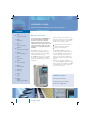
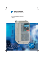
LIFT INVERTER SERIES
L1000 A
EN
DE
ES
FR
IT
L
For
n
nisatio
Moder
and
n
tallatio
s
n
I
w
Ne
YASKAWA L1000A
FOR HIGH PERFORMANCE LIFT APPLICATION
Content
Contents
Page 2
Experience & Innovation
Experience & Innovation
Page 3
Main Features
Page 4
Energy & cost efficiency
Page 5/6
For more than 90 years YASKAWA has
been manufacturing and supplying
mechatronic products for machine
building and industrial automation. Its
standard products as well as tailor-made
solutions are famous and have a high
reputation for outstanding quality and
durability.
Based on many years of experience and
application oriented innovation the L1000A
provides high-performance characteristics
offering a set of attractive features:
YASKAWA has a track record also of
manufacturing and supplying inverters to
drive the lift industry: more than 60.000
sold lift inverter units every year.
The L1000A Inverter Series is a dedicated
inverter drive for lift applications suitable
for both modernisation projects and new
installations.
The YASKAWA L1000A uses special
hardware designed for 3 Million starts and
more than 70.000 hrs of maintenance free
operation. It provides advanced control
functions to run induction and PM motor
applications in geared or gearless elevator
systems.
With its motor capacities ranging from
4 to 75 kW the L1000A is capable of driving
almost any elevator. In addition, the L1000A
is quickly installed and can be integrated
into most control systems.
Energy and Life-Cycle-Cost efficiency
Simple and stress-free handling
Safe and comfortable rides
Simple & stress free handling
Page 7/8
Safe & comfortable rides
Page 9
Specifications
Page 10
Connection Diagram
Page 11
Terminal Functions
Page 12/13
Dimensions
Page 14
Options
L1000A main features
Page 15
9 Energy & cost efficiency
9 Simple & stress-free handling
9 Safe & comfortable rides
Options
Ratings & Type Descriptions
2
YASKAWA L1000A
Main Features:
Energy & cost efficiency
Safe & comfortable rides
The YASKAWA L1000A provides technical features and special
design which enhance product applicability and reliability for first
class efficiency.
Based on years of experience in
the market YASKAWA includes
many functions & features to ensure
the elevator works smooth and
gives passengers a comfortable lift.
Designed for three million starts at 165% output current and more than
70,000 hrs of maintenance-free operation
Service Performance Monitor
New light load function for UPS (Uninterrupted Power Supply)
Advanced motor & drive technology for gearless PM motor control
Built-in braking transistor for all models up to 30 kW
Simple handling
The L1000A is strictly responds to the requirements of the lift markets.
It shows great system flexibility and user focus.
Software supports all common controllers in the market
Lift language (Hz, m/s, rpm, levelling speed, service speed, nominal speed)
Multifunction terminal board with parameter backup function.
Software support tool DriveWizard Plus
Various types of Auto-Tuning for induction and gearless permanent
magnet motors
Powerful torque characteristics
LCD operator for parameter handling as standard
USB copy unit
Specialized lift software based
on many years of experience
Input voltage sensors for phase
loss detection
Simple and efficient brake
sequence
High levelling accuracy even in
open-loop, thanks to load detection
during run
Five independent settings of
S-curves to prevent jerks
Improved torque ripple suppression
Torque compensation at start
without load sensor
Overshoot and anti-vibration control
De-magnetization protection for
PM motor
Rescue Operation Function
Only one motor contactor needed
in compliance with EN81-1
Four relay outputs for each fault and brake control.
3
Energy & cost efficiency
Content
Advanced motor/drive technology
High performance current vector control technology for induction and synchronous motor operation
Single software parameter to switch between motor types
Perfect for a wide range of lift applications
Control Modes
Synchronous motors (SPM/IPM drive): Closed Loop Vector for PM
Induction motors: V/f control, Open-Loop Vector, Closed-Loop Vector Control
Switch between motor types
with a single parameter
L1000
Induction motor
Synchronous
SPM motor
Synchronous IPM motor
(YASKAWA Super-Energy)
Extended inverter range with built-in braking transistor
L1000A
Previous
models
L1000A provides built-in braking transistor for all inverter models up to 30 kW
Capacity
4
4.0 kW
18.5 kW
YASKAWA L1000A
30 kW
Simple Handling
Auto-Tuning options
Auto-Tuning methods optimise motor handling performance. Rotational Auto-Tuning and stationary Auto-Tuning are available
for both induction motors and synchronous motors.
Auto-Tuning for induction motors
Rotational Auto-Tuning
Rotational Auto-Tuning gives most accurate results and is highly recommended. Ropes have to be removed.
Stationary Auto-Tuning 1
Automatically calculates motor parameters needed for vector control. If ropes can not be removed
Stationary Auto-Tuning for
Line-to-Line Resistance
Used for V/f Control or in vector control modes when the drive was set up properly before and
the motor cable has changed.
Stationary Auto-Tuning 2
When motor test report is available. The no-load current and the rated slip must be entered from the test
report, all other motor-related parameters are calculated automatically. Use if ropes can not be removed and
if slip and no-load current data are available.
Auto-Tuning for PM motors
Motor Parameter Settings
Use if a motor test report is available. Input motor data like on test report. Make sure to convert data into the
correct unit before if necessary.
Stationary Auto-Tuning
Use if a motor test report is not available. Input motor data like on name plate. Make sure to convert data into
the correct unit before. The drive automatically calculates the additionally required motor data.
Stationary Auto-Tuning for Stator
Tunes stator resistance only. Should be performed if the motor cable has changed.
Resistance:
Initial Pole Search Tuning
Judges if the rotor position can be detected without rotation or not and tunes related parameters. Should be
performed after motor Auto-Tuning to decide which encoder offset tuning method is used.
Rotating Encoder
Offset Tuning
Tunes the encoder offset of an absolute encoder while rotating the motor. Should be performed with no load,
i. e. ropes have to be removed or car must be balanced.
Stationary Encoder Offset Tuning
Tunes the encoder offset of an absolute encoder without rotating the motor. Can only be used with an
IPM motor. If offset can not be tuned properly by this method run Rotating Encoder Offset Tuning
5
Simple handling
Powerful torque characteristics
Control mode
V/f control
For modernization applications,
when auto-tuning is not possible
(e. g. motor current is not known)
Open-loop vector
For modernization and new installations
Closed-loop vector control
For geared and gearless induction
motors
Closed-loop vector control for PM
motors
For geared and gearless permanent
magnet motors
Starting torque
Speed range
Motor encoders and option cards
150% at 3 Hz
1:40
-
200% at 1 Hz
1:120
-
200% at 0 rpm
1:1500
200% at 0 rpm
1:1500
Incremental encoders:
- PG-X3 (Line driver )
- PG-B3 (Complementary)
Incremental encoders:
- PG-X3 (Line driver)
- PG-B3 (Complementary)
Absolute encoders:
- PG-F3 (Endat 2.2/22, HIPERFACE)
- PG-E3 (Heidenhain ERN1387)
- PG-R3 (Resolver)
USB copy unit availlable
Also available: a USB copy unit as an even faster and more
convenient way to back up settings and instantly program
the drive.
LCD operator for simple parameter handling
All standard versions are equipped with an LCD operator including:
8 operating languages
Copy function: to upload and download parameter
settings instantly
Setup Mode: prepares initial parameter to start
the drive running right away
Verify function: checks parameters which have been
changed from default values
6
YASKAWA L1000A
Simple handling
Multifunction Terminal Board
Terminal board with a Parameter Backup Function
The terminal board’s ability to save parameter setting data makes it easy to get the
application back online in the event of a failure requiring drive replacement.
L1000A Terminal Board
Parameter
Name
Number
Setting
ND/HD
C6-01
1
Cont
Co
ntro
roll Mo
Mode
de
A1-02
02
0
Freque
Freq
Fr
uenc
enc
ncyy Re
Refe
Ref
fere
fere
renc
ncee Se
nc
Sele
Sel
lect
ctitio
ion
ion
b1-001
1
Run Co
Run
Ru
Comm
Comm
mman
andd Se
an
Sele
Sel
lect
ctitio
ion
ion
b1-002
1
DriveWizard Plus
Engineering tool DriveWizard Plus
To adjust and edit parameters, access
all monitors, create customized operation
sequences, and observe drive
performance with the oscilloscope
function
Drive Replacement feature in DriveWizard
Plus: automatically converts previous
product parameter values to L1000A
parameters, saving valuable time during
equipment replacement and application
upgrading
The inverter drive is equipped with a USB
port for connecting to a PC
Drive Replacement Function
Previous Model
L1000A
Varispeed F7
Instant setup
DriveWizard Plus
Varispeed F7S
Note: To obtain a copy of DriveWizard Plus, contact a YASKAWA representative.
7
Safe & comfortable rides
Torque compensation at start without load sensor
New sensor-less torque compensation function includes the YASKAWA advanced anti-rollback function*, preventing shock at
start to ensure a smooth start
*Anti-rollback function: provides the right amount of torque compensation to suppress shock and prevent speed variations when the brake is released.
Torque reference
Torque reference
Motor speed
Rollback
7.5
8.0
8.5
Motor speed
Rollback suppressed
9.0
9.5
10
10.5 11
11.5
7.5
12 (sec.)
Zero servo gain 2 (S3-02) Before adjustment
8.0
8.5
9.0
9.5
10
10.5 11
11.5
12 (sec.)
Zero servo gain 2 (S3-02) After adjustment
Improved torque ripple suppression
Previous model
current
Previous series
Software-base
compensation
current
L1000A series
Software-base
compensation
L1000A
Torque ripple comparison
(closed-loop vector at 0 speed)
Smooth start/stop due to optimised
torque ripple suppression.
Precise motor torque performance
for comfortable acceleration and
deceleration characteristics
On-Delay compensation function nASIC
Overshoot and anti-vibration control
900
900
Speed (rpm)
1050
Speed (rpm)
1050
750
0
0.5
1
Previous speed control
8
Time (S)
Overshoot at the end
of accerleration is
suppressed
750
0
0.5
1
Time (S)
w/Feed Forward control
YASKAWA L1000A
Feed forward function allows ideal
speed response.
Acceleration and deceleration
compensation prevent vibration
and overshoot.
Adjustment of S-curve settings for
acceleration and deceleration to
ensure a perfectly smooth ride.
Safe & comfortable rides
UPS and light-load direction search function for rescue operation
A single-phase 230 V UPS or
48 – 96 VDC battery (24 V control power
supply) provides the inverter drive with
the necessary power for evacuation.
In case of power failure the L1000A can
bring the cabin to the next floor for
evacuation using the UPS.
A “light-load direction search” function
triggered by the controller detects the
light direction of the lift.
UPS
48–96 VDC
220 V
single
phase
24 VDC
UPS wiring and operation
24 V
power supply
unit
Back-up battery wiring and operation
*For clarity, the illustrations have been simplified, omitting several switches and control signals.
Long lifetime design
Designed for 10 years of maintenancefree operation
IGBTs are designed 3 million full load
starts.
Cooling fan and capacitors have
been carefully selected for a lift life
of at least 70.000 hrs of maintenance free operation.
Performance life monitor
The L1000A is equipped with
performance life monitors that notify
the user of part wear and maintenance
periods to prevent problems before they
occur.
Alarm!
Operator
Display
Corresponding
Component
LT-1
Cooling fan
LT-2
Capacitors
LT-3
Inrush prevention
relay
LT-4
IGBTs
Alarm signals can be transmitted to a PLC or control device.
9
Safe & comfortable rides
Safety features as standard functions
One contactor solution according to EN81-1*
L1000A is approved for being implemented to system design according to
EN954-1 Cat. 3, stop category 0, ISO EN13849-1 PLd and IEC EN 61508 SIL2.
An External Device Monitor (EDM) function has also been added to monitor the
safety status of the drive.
* Under Development
Safety Chain
Circuit
Elevator Controller
Contactor Close
Command
Contactor Check
(Restart Permission)
KD1
K1
H1
H2 HC Up/Down
Speed selection; …
Safe Disable Monitor
=58)
(NC, H2-
YASKAWA CIMR-LC
K2
M
10
YASKAWA L1000A
Standard Specifications
Item
Control Method
0.01 to 120 Hz
Frequency Accuracy
(Temperature Fluctuation)
Digital referece: within ±0.01% of the max. output frequency (−10 to +40°C)
Analog referece: within ±0.1% of the max. output frequency (25°C ±10°C)
Digital referece: 0.01 Hz
Analog referece: 0.03 Hz / 60 Hz (11 bit)
Control Characteristics
Output Frequency Resolution
Protection Function
V/f Control, Open Loop Vector Control, Closed Loop Vector Control, Closed Loop Vector for PM
Frequency Control Range
Frequency Setting Resolution
Operating Environment
Specifications
0.001 Hz
Frequency Setting Signal
-10 to +10 V, 0 to +10 V
Starting Torque
150%/3 Hz (V/f Control), 200%/0.3 Hz*1 (Open Loop Vector Control), 200%/0 r/min*1 (Closed Loop Vector Control, Closed Loop Vector
Control for PM
Speed Control Range
1:1500 (Closed Loop Vector Control and Closed Loop Vector for PM) 1:200 (Open Loop Vector Control) 1:40 (V/f Control
Speed Control Accuracy
±0.2% in Open Loop Vector Control (25°C ±10°C) *2, ± 0.02% in Closed Loop Vector Control (25°C±10°C)
Speed Response
10 Hz in Open Loop Vector (25°C ±10°C), 50 Hz in Closed Loop Vector Control (25°C±10°C) (excludes temperature fluctuation when
performing Rotational Auto-Tuning)
Torque Limit
All Vector Control allows separate settings in four quadrants (available in OLV, CLV, CLV/PM)
Accel/Decel Time
0.00 to 600.00 s (4 selectable combinations of independent acceleration and deceleration settings)
Braking Torque
Drives of 200/400 V 30 kW or less have a built-in braking transistor.
V/f Characteristics
Freely programmable
Main Control Functions
Inertia Compensation, Position Lock at Start and Stop/Anti-Rollback Function, Overtorque/Undertorque Detection, Torque Limit, Speed
Reference, Accel/decel Switch, 5 Zone Jerk Settings, Auto-tuning (Stationary and Rotational Motor/Encoder Offset Tuning), Dwell,
Cooling Fan on/off Switch, Slip Compensation, Torque Compensation, DC Injection Braking at Start and Stop, MEMOBUS/Modbus
Comm. (RS-422/485 max, 115.2 kbps), Fault Restart, Removable Terminal Block with Parameter Backup Function, Online Tuning,
High Frequency Injection, Short Floor, Rescue Operation(Light Load Direction Search Function), Inspection Run, Brake Sequence,
Speed related parameters with elevator units display, etc.
Motor Protection
Motor overheat protection based on output current
Momentary Overcurrent
Protection
Drive stops when output current exceeds 200%
Overload Protection
Drive stops after 60 s at 150% (acceleration current 175%) of rated output current*3
Overvoltage Protection
200 V class: Stops when DC bus exceeds approx. 410 V, 400 V class: Stops when DC bus exceeds approx. 820 V
Undervoltage Protection
200 V class: Stops when DC bus exceeds approx. 190 V, 400 V class: Stops when DC bus exceeds approx. 380 V
Heatsink Overheat Protection
Thermistor
Stall Prevention
Stall prevention during acceleration/deceleration and constant speed operation
Ground Fault Protection
Protection by electronic circuit*4
Charge LED
Charge LED remains lit until DC bus has fallen below approx. 50 V
Area of Use
Indoors
Ambient Temperature
−10 to +50°C (open chassis), −10 to +40°C (NEMA Type 1)
Humidity
95% RH or less (no condensation)
Storage Temperature
−20 to +60°C (short-term temperature during transportation)
Altitude
Up to 1000 meters (output derating of 1% per 100 m above 1000 m, max. 3000 m)
Shock
10 Hz to 20 Hz, 9.8 m/s2 max. 20 Hz to 55 Hz, 5.9 m/s2 (200 V: 45 kW or more, 400 V: 55 kW or more) or 2.0 m/s2 max. (200 V: 55
kW or less, 400 V: 75 kW or less)
Safety Standard
EN954-1 safe category 3 stop category 0; EN ISO 13849-1; IEC EN 61508 SiL2
Protection Design
IP00 open-chassis, IP20, NEMA Type 1 enclosure
*1:
*2:
*3:
*4:
Requires a drive with recommended capacity.
Speed control accuracy may vary slightly depending on installation conditions or motor used. Contact Yaskawa for details.
Overload protection may be triggered when operating with 150% of the rated output current if the output frequency is less than 6 Hz.
Protection may not be provided under the following conditions as the motor windings are grounded internally during run:
• Low resistance to ground from the motor cable or terminal block. • Drive already has a short-circuit when the power is turned on.
11
Connection Diagram
Content
DC reactor q
(optional)
Terminals -, +1, +2, B1, B2 are
for connection options. Never connect
power supply lines to these terminals
U
Thermal relay
(option)
X
Braking resistor
(option)
Jumper
+2
+1
B1
B2
w
U/T 1
Main Circuit
V/T 2
Three-phase
R/L1
power supply
200 to 240 Vac or S/L2
380 to 480 Vac
T/L3
50/60 Hz
R/L1
EMC Filter
T/L3
Up command / Stop
S1
Down command / Stop
S2
Nominal Speed
S3
W/T 3
L1000A
S/L2
Control Circuit
Motor
M
Shielded
Cable
Ground
Option card connectors
U
V
W
CN5-C
CN5-B
Multi-function
digtial inputs
(default setting)
Inspection Operation
S4
Intermediate Speed 1
S5
Leveling Speed
S6
Not Used
S7
Not Used
Filter
CN5-A
Terminal board
jumper and switch
DIP Switch S2
Term. Res. On/Off
Jumper S3
H1, H2
Sink/Source Sel.
S8
SN
MA
Sink / Source mode
selection wire link
(default: Sink)
e
SC
MB
MC
SP
+ 24 V
+V
M1
Shield ground terminal
M2
Power supply +10.5 Vdc, max. 20 mA
M3
M4
2 kΩ
Multi-function
analog/ pulse
train inputs
A1
Analog Input 1 (Speed Bias)
-10 to +10 Vdc (20 kΩ)
A2
Analog Input 2 (Not used)
-10 to +10 Vdc (20 kΩ)
M5
M6
AC
0V
Fault relay output
250 Vac, max. 1 A
30 Vdc, max. 1 A
(min. 5 Vdc, 10 mA)
Multi-function relay output (Brake Release Command)
250 Vac, max. 1 A
30 Vdc, max. 1 A
(min. 5 Vdc, 10 mA)
Multi-function relay output (Motor Contactor Close Command)
250 Vac, max. 1 A
30 Vdc, max. 1 A
(min. 5 Vdc, 10 mA)
Multi-function relay output (Drive Ready)
250 Vac, max. 1 A
30 Vdc, max. 1 A
(min. 5 Vdc, 10 mA)
P1
−V
C1
P2
Termination resistor
(120 Ω, 1/2 W)
R+
DIP
Switch S2
C2
Photo Coupler 1
(During Frequency Output)
Digital output
5 to 48 Vdc
2 to 50 mA
(default setting)
Photo Coupler 2
(not used)
R
MEMOBUS/Modbus
comm. RS485/422
max. 115.2 kBps
FM
S+
S
FM
IG
H1
AM
AC
0V
AM
+
Multi-function analog output 1
(Output Speed)
-10 to +10 Vdc (2mA)
+
Multi-function analog output 2
(Output Current)
-10 to +10 Vdc (2mA)
H2
E (G)
Safe Disable inputs
r
shielded line
DM +
HC
EDM (Safety Electronic Device Monitor)
DM
twisted-pair shielded
control circuit termina
main circuit terminal
q Remove the jumper when installing a DC reactor. Models CIMR-LC2A0085 through 0115 and 4A0045 through 0150 come with a built-in DC reactor.
w The drive provides a stop function in compliance with Stop Category 0 (EN60204-1) and “Safe Torque Off” (IEC61800-5-2). It has been designed to meet
the requirements of the EN954-1/ISO13849-1, Category 3 and IEC61508, SIL2. Using this function the number of motor contactors can be reduced to one.
e Never short terminals SP and SN, as doing so will damage the drive.
r Disconnect the wire jumper between H1 - HC and H2 - HC when utilizing the Safe Disable inputs.
Note: 1. The drive should be implemented in the system in a way so that a drive fault causes the safety chain to open. Always use terminal MA-MB-MC for this purpose.
2. Even though no fault is present conditions where the drive can not start can occur, e.g. when the Digital Operator is left in the Programming Mode. Use the “Drive Ready” output (default set to terminals M5-M6) to interlock operation in such situations.
12
YASKAWA L1000A
Dimensions
Enclosures
Enclosures of standard products vary depending on the model. Refer to the table below.
Voltage class
Model
200 V
CIMR-LC2A
400 V
CIMR-LC4A
0018 0025 0033 0047 0060 0075 0085 0115 0145 180 0009 0015 0018 0024 0031 0039 0045 0060 0075 0091 0112 0150
Max. Applicable Motor
Capacity [kW]
4.0
5.5
7.5
11
IP20
15
18.5
22
30
37
Standard
45
4.0
5.5
7.5
11
Note*
15
18.5
22
30
37
45
55
Standard on request
75
Note*
Note*: with reduced bending space
IP20 (with reduced bending space)
4-d
W
H2
W1
W1
4-d
t2
4-d
H3
H2
H
H1
H0
H
H
H1
H1
H0
W1
D1
H2
H3
t1
D
W
D1
D
t1
Max 10
Fig. 1
Fig. 2
D
Max 10
W
D1
Fig. 3
200 V Class
Model CIMRLC2A
Max. applicable
motor capacity [kW]
0018
0025
0033
0047
0060
0075
0085
0115
0145
0180
4.0
5.5
7.5
11
15
18.5
22
30
37
45
Figure
W
H
140
260
D
W1
Dimensions in mm
H0
H1
H2
H3
D1
t1
t2
d
3.5
164
Fig. 1
180
Fig. 2
Fig. 3
167
122
248
6
160
55
-
254
279
300
350
365
534
614
329
630
283
260
550
80
110
W
H
D
W1
Dimensions in mm
H0
H1
H2
H3
D1
140
260
220
187
Weight
(kg)
197
192
258
284
335
195
220
350
400
450
385
435
535
75
8
7.5
15
134
164
M5
5
-
78
100
M6
2.3
4.0
5.6
8.7
9.7
23
28
40
400 V Class
Model CIMRLC4A
Max. applicable
motor capacity [kW]
0009
0015
0018
0024
0031
0039
0045
0060
0075
0091
0112
0150
4.0
5.5
7.5
11
15
18.5
22
30
37
45
55
75
Figure
t1
t2
d
164
3.5
122
167
Fig. 1
180
300
220
254
279
350
465
515
187
197
258
258
630
258
Fig. 3
329
248
6
160
192
195
220
55
-
284
400
450
335
385
435
510
495
283
550
535
-
M5
65
100
120
105
180
110
2.3
3.9
5.4
5.7
8.3
23
27
75
78
8
7.5
5
260
730
Weight
(kg)
M6
39
45
46
13
Content
Options
Name
Purpose
Model
AC Chokes
Reducing Harmonics
For detailed information contact
YASKAWA.
Analog input
Enables high-precision and high-resolution analog speed reference setting.
• Input signal level: −10 to +10 Vdc (20 kΩ) 4 to 20 mA (500 Ω)
• Input channels: 3 channels, DIP switch for input voltage/input current selection
• Input resolution: Input voltage 13 bit signed (1/8192) Input current 1/6554
AI-A3
Digital Input
Enables 16-bit digital speed reference setting.
• Input signal: 16 bit binary, 2 digit BCD + sign signal + set signal
• Input voltage: +24 V (isolated)
• Input current: 8 mA
Selectable Parameter: 8 bit, 12 bit, 16 bit
DI-A3
CANopen
communications interface
Used for running or stopping the drive, setting or referencing parameters and monitoring
output frequency, output current, or similar items through CANopen communication with
the host controller.
SI-S3
Analog monitor
Outputs analog signal for monitoring drive output state (output freq., output current etc.)
• Output resolution: 11 bit signed (1/2048)
• Output voltage: −10 to +10 Vdc (non-isolated)
• Output channels: 2 channels
AO-A3
Digital output
Outputs isolated type digital signal for monitoring drive run state (alarm signal, zero speed
detection, etc.). Output channel: Photo coupler 6 channels (48 V, 50 mA or less)
Relay contact output 2 channels 250 Vac, 1 A or less 30 Vdc, 1 A or less
DO-A3
Open collector PG
interface
For control modes requiring a PG encoder for motor feedback.
• Phase A, B, and Z pulse (3-phase) inputs (complementary type)
• PG frequency range: Approx. 50 kHz max.
• Power supply output for PG: +24 V, max. current 30 mA
• Pulse monitor output: Open collector, +24 V, max. current 30 mA
• Power supply output for PG: +12 V, max. current 200 mA
PG-B3
Line Driver PG
interface
For control modes requiring a PG encoder for motor feedback.
• Phase A, B, and Z pulse (differential pulse) inputs (RS-422)
• PG frequency range: up to 300 kHz (approx.)
• Pulse monitor output: RS-422
• Power supply output for PG: +5 V or +12 V, max. current 200 mA
PG-X3
Absolute encoder
Endat Motor Feedback
PG-F3 (Endat. 2.2/22, HIPERFACE)
Absolute encoder
Heidenhain Motor Feedback
PG-E3 (Heidenhain ERN1387)
Absolute encoder
Resolver Motor Feedback
PPG-R3 (Resolver)*
LED Operator
Easy long distance reading
JVOP-182
Braking Resistor
Used to shorten the deceleration time by dissipating regenerative energy
For detailed information contact
YASKAWA.
Braking Chopper Unit
Shortened deceleration time results when used with a Braking Resistor Unit.
For units above 30kW
CDBR series
24 V Power Supply
Provides power supply for the control circuit and option boards. Note: Parameter settings
cannot be changed when the drive is operating solely from this power supply.
PS-A10H
PS-A10L
• Adapter for connecting the drive to the USB port of a PC
• Can copy parameter settings easily and quickly to be later transferred to another drive.
JVOP-181
Cable for connecting the LCD operator.
WV001: 1 m
WV003: 3 m
USB Copy Unit
(RJ-45/USB compatible
plug)
LCD operator extension
cable
*coming soon
Note: contact the manufacturer in question for availability and specifications of non-YASKAWA products.
14
YASKAWA L1000A
Options
Name
Purpose
Model
Reduces noise from the line that enters into the drive input
power system. Should be installed as close as possible to the
drive.
Input noise filter
Filter:
FB-40014A
FB-40025A
FB-40025A
FB-40044A
FB-40044A
FB-40060A
FB-40060A
FB-40072A
FB-40105A
FB-40105A
FB-40170A
FB-40170A
Three-phase 400 V
CIMR-AC4A0009xAA
CIMR-AC4A0015xAA
CIMR-AC4A0018xAA
CIMR-AC4A0024xAA
CIMR-AC4A0031xAA
CIMR-AC4A0039xAA
CIMR-AC4A0045xAA
CIMR-AC4A0060xAA
CIMR-AC4A0075xAA
CIMR-AC4A0091xAA
CIMR-AC4A0112xAA
CIMR-AC4A0150xAA
Footmounted:
yes
yes
yes
yes
yes
no
no
no
no
no
no
no
Ratings & Type Descriptions
Model Number Key
CIMR-
L
AC Drive
C
4
A
0015
B
A
A
Design Revision Order
L1000A Series
Environmental Specification
Region Code
T
A
C
A
M
N
S
K
Asia
Japan
Europe
Voltage Class
2
4
Standard
Humidity, dust
Oil
Shock, vibration
Gas
Note: Contact YASKAWA for more information
on environmental tolerance specifications.
3-phase, 200-240 Vac
3-phase, 380-480 Vac
Enclosure Type
Customized Specifications
B
A
C
Standard model
200 V
0018
0025
0033
0047
0060
0075
0085
0115
0145
0180
Rated output current [A]
18*1
25*1
33*1
47*1
60*1
75*1
85*1
115*1
145*1
180*1
IP20
IP20 with reduced
bending space
400 V
Max. applicable motor* [kW]
4.0
5.5
7.5
11
15
18.5
22
30
37
45
3
Rated output current [A]
Max. applicable motor*3 [kW]
0009
9.2*1
4.0
0015
14.8*1
5.5
0018
18*1
7.5
0024
24*1
11
0031
31*1
15
0039
39*1
18.5
0045
45*1
22
0060
60*1
30
0075
75*5
37
0091
91*1
45
0112
112*1
55
0150
150*2
75
*1: This value assumes a maximum carrier frequency of 8 kHz. Increasing the carrier frequency requires a reduction in current.
*2: This value assumes a maximum carrier frequency of 5 kHz. Increasing the carrier frequency requires a reduction in current.
*3: The motor capacity (kW) refers to a Yaskawa 4-pole, 60 Hz, 200 V motor or 400 V motor. The rated output current of the drive output amps should be equal to or greater than the motor rated current.
15
YASKAWA Electric Europe GmbH
Hauptstr. 185
65760 Eschborn
Deutschland / Germany
+49 6196 569-300
[email protected]
www.yaskawa.eu.com
L
Specifications are subject to change without notice
for ongoing product modifications and improvements.
© YASKAWA Electric Europe GmbH. All rights reserved.
Literature No. YEG_INV_L1000A_EN_v1_0909
Printed in Germany, September 2009