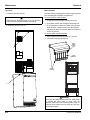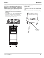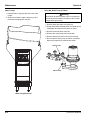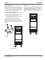
1
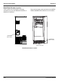
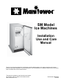
SM Model
Ice Machines
Installation
Use and Care
Manual
Thank you for selecting a Manitowoc Ice Machine, the dependability leader in ice making equipment and related
products. With proper installation, care and maintenance, your new Manitowoc Ice Machine will provide you with many
years of reliable and economical performance.
This manual is updated as new information and models
are released. Visit our website for the latest manual.
www.manitowocice.com
Part Number 000001590
09/2008
Safety Notices
Procedural Notices
As you work on this Ice Machine, be sure to pay close
attention to the safety notices in this manual.
Disregarding the notices may lead to serious injury and/
or damage to the ice machine.
As you work on this Ice Machine, be sure to read the
procedural notices in this manual. These notices supply
helpful information which may assist you as you work.
Throughout this manual, you will see the following types
of safety notices:
Throughout this manual, you will see the following types
of procedural notices:
Important
! Warning
PERSONAL INJURY POTENTIAL
Do not operate equipment that has been misused,
abused, neglected, damaged, or altered/modified
from that of original manufactured specifications.
! Warning
Text in a Warning box alerts you to a potential
personal injury situation. Be sure to read the
Warning statement before proceeding, and work
carefully.
! Caution
Text in a Caution box alerts you to a situation in
which you could damage the ice machine. Be sure
to read the Caution statement before proceeding,
and work carefully.
Text in an Important box provides you with
information that may help you perform a procedure
more efficiently. Disregarding this information will
not cause damage or injury, but it may slow you
down as you work.
NOTE: Text set off as a Note provides you with simple,
but useful, extra information about the procedure you
are performing.
Read These Before Proceeding:
! Caution
Proper installation, care and maintenance are
essential for maximum ice production and troublefree operation of your ice machine.
Read and understand this manual. It contains
valuable care and maintenance information. If you
encounter problems not covered by this manual, do
not proceed, contact Manitowoc Foodservice. We
will be happy to provide assistance.
Important
Routine adjustments and maintenance procedures
outlined in this manual are not covered by the
warranty.
Table of Contents
Section 1
General Information
Model Numbers . . . . . . . . . . . . . . . . . . . . . . . . . . . . . . . . . . . . . . . . . . . . . . . . .
How to Read a Model Number . . . . . . . . . . . . . . . . . . . . . . . . . . . . . . . . . . . . .
Accessories . . . . . . . . . . . . . . . . . . . . . . . . . . . . . . . . . . . . . . . . . . . . . . . . . . . .
Legs . . . . . . . . . . . . . . . . . . . . . . . . . . . . . . . . . . . . . . . . . . . . . . . . . . . . . .
Drain Pump . . . . . . . . . . . . . . . . . . . . . . . . . . . . . . . . . . . . . . . . . . . . . . . . .
Manitowoc Cleaner and Sanitizer . . . . . . . . . . . . . . . . . . . . . . . . . . . . . . . .
Arctic Pure Water Filter System . . . . . . . . . . . . . . . . . . . . . . . . . . . . . . . . .
Model/Serial Number Location . . . . . . . . . . . . . . . . . . . . . . . . . . . . . . . . . . . . .
Owner Warranty Registration Card . . . . . . . . . . . . . . . . . . . . . . . . . . . . . . . . .
General . . . . . . . . . . . . . . . . . . . . . . . . . . . . . . . . . . . . . . . . . . . . . . . . . . . .
Commercial Warranty Coverage . . . . . . . . . . . . . . . . . . . . . . . . . . . . . . . . . . .
General . . . . . . . . . . . . . . . . . . . . . . . . . . . . . . . . . . . . . . . . . . . . . . . . . . . .
Parts . . . . . . . . . . . . . . . . . . . . . . . . . . . . . . . . . . . . . . . . . . . . . . . . . . . . . .
Labor . . . . . . . . . . . . . . . . . . . . . . . . . . . . . . . . . . . . . . . . . . . . . . . . . . . . . .
Exclusions . . . . . . . . . . . . . . . . . . . . . . . . . . . . . . . . . . . . . . . . . . . . . . . . . .
Authorized Warranty Service . . . . . . . . . . . . . . . . . . . . . . . . . . . . . . . . . . .
Residential Ice Machine Limited Warranty . . . . . . . . . . . . . . . . . . . . . . . . . . .
1-1
1-1
1-1
1-1
1-1
1-1
1-1
1-2
1-3
1-3
1-3
1-3
1-3
1-3
1-3
1-3
1-4
Section 2
Installation Instructions
Installation Prerequisites . . . . . . . . . . . . . . . . . . . . . . . . . . . . . . . . . . . . . . . . .
General . . . . . . . . . . . . . . . . . . . . . . . . . . . . . . . . . . . . . . . . . . . . . . . . . . . . . . . .
Ice Machine Dimensions . . . . . . . . . . . . . . . . . . . . . . . . . . . . . . . . . . . . . . . . . .
Air-Cooled Ice Machines . . . . . . . . . . . . . . . . . . . . . . . . . . . . . . . . . . . . . . .
Minimum Cut-Out for Built-In Installations/ . . . . . . . . . . . . . . . . . . . . . . . . .
Location of Ice Machine . . . . . . . . . . . . . . . . . . . . . . . . . . . . . . . . . . . . . . . . . .
Clearances . . . . . . . . . . . . . . . . . . . . . . . . . . . . . . . . . . . . . . . . . . . . . . . . .
Electrical Service . . . . . . . . . . . . . . . . . . . . . . . . . . . . . . . . . . . . . . . . . . . . . . . .
General . . . . . . . . . . . . . . . . . . . . . . . . . . . . . . . . . . . . . . . . . . . . . . . . . . . .
Voltage . . . . . . . . . . . . . . . . . . . . . . . . . . . . . . . . . . . . . . . . . . . . . . . . . . . .
Minimum Circuit Ampacity . . . . . . . . . . . . . . . . . . . . . . . . . . . . . . . . . . . . .
Electrical Requirements . . . . . . . . . . . . . . . . . . . . . . . . . . . . . . . . . . . . . . .
Maximum breaker size & Minimum Circuit Amperage Chart . . . . . . . . . . .
GFCI Requirements . . . . . . . . . . . . . . . . . . . . . . . . . . . . . . . . . . . . . . . . . .
Water Supply and Drain Requirements . . . . . . . . . . . . . . . . . . . . . . . . . . . . . .
Water Supply . . . . . . . . . . . . . . . . . . . . . . . . . . . . . . . . . . . . . . . . . . . . . . .
Water Inlet Lines . . . . . . . . . . . . . . . . . . . . . . . . . . . . . . . . . . . . . . . . . . . . .
Drain Connections . . . . . . . . . . . . . . . . . . . . . . . . . . . . . . . . . . . . . . . . . . .
Water Supply and Drain Line Sizing/Connections . . . . . . . . . . . . . . . . . . .
Step-by-Step Installation Procedure . . . . . . . . . . . . . . . . . . . . . . . . . . . . . . . .
Leveling the Ice Machine . . . . . . . . . . . . . . . . . . . . . . . . . . . . . . . . . . . . . . . . . .
Drain Pump Option . . . . . . . . . . . . . . . . . . . . . . . . . . . . . . . . . . . . . . . . . . . . . .
Leg Option . . . . . . . . . . . . . . . . . . . . . . . . . . . . . . . . . . . . . . . . . . . . . . . . . . . . .
Reversing Door Swing . . . . . . . . . . . . . . . . . . . . . . . . . . . . . . . . . . . . . . . . . . . .
Installation Check List . . . . . . . . . . . . . . . . . . . . . . . . . . . . . . . . . . . . . . . . . . . .
Before Starting the Ice Machine . . . . . . . . . . . . . . . . . . . . . . . . . . . . . . . . . . . .
Part Number 000001590
2-1
2-1
2-2
2-2
2-2
2-3
2-3
2-4
2-4
2-4
2-4
2-4
2-4
2-4
2-5
2-5
2-5
2-5
2-5
2-6
2-7
2-8
2-8
2-9
2-10
2-11
1
Table of Contents (continued)
Section 3
Ice Machine Operation
Component Identification . . . . . . . . . . . . . . . . . . . . . . . . . . . . . . . . . . . . . . . . .
Control Panel . . . . . . . . . . . . . . . . . . . . . . . . . . . . . . . . . . . . . . . . . . . . . . . . . . .
Functions . . . . . . . . . . . . . . . . . . . . . . . . . . . . . . . . . . . . . . . . . . . . . . . . . . .
Safety Timers . . . . . . . . . . . . . . . . . . . . . . . . . . . . . . . . . . . . . . . . . . . . . . . .
Sequence of Operation . . . . . . . . . . . . . . . . . . . . . . . . . . . . . . . . . . . . . . . . . . .
Operational Checks . . . . . . . . . . . . . . . . . . . . . . . . . . . . . . . . . . . . . . . . . . . . . .
General . . . . . . . . . . . . . . . . . . . . . . . . . . . . . . . . . . . . . . . . . . . . . . . . . . . .
Water Level . . . . . . . . . . . . . . . . . . . . . . . . . . . . . . . . . . . . . . . . . . . . . . . . .
Bin Thermostat Adjustment . . . . . . . . . . . . . . . . . . . . . . . . . . . . . . . . . . . . .
Testing and Adjusting the Bin Thermostat . . . . . . . . . . . . . . . . . . . . . . . . . .
Cube Weight Adjustment . . . . . . . . . . . . . . . . . . . . . . . . . . . . . . . . . . . . . . .
3-1
3-2
3-2
3-2
3-3
3-4
3-4
3-4
3-4
3-4
3-5
General . . . . . . . . . . . . . . . . . . . . . . . . . . . . . . . . . . . . . . . . . . . . . . . . . . . . . . . .
Interior Cleaning and Sanitizing . . . . . . . . . . . . . . . . . . . . . . . . . . . . . . . . . . . .
General . . . . . . . . . . . . . . . . . . . . . . . . . . . . . . . . . . . . . . . . . . . . . . . . . . . .
In Place Cleaning/Sanitizing Procedure . . . . . . . . . . . . . . . . . . . . . . . . . . .
Cleaning Procedure . . . . . . . . . . . . . . . . . . . . . . . . . . . . . . . . . . . . . . . . . . .
Removal of Parts For Cleaning/Sanitizing . . . . . . . . . . . . . . . . . . . . . . . . . .
Exterior Cleaning . . . . . . . . . . . . . . . . . . . . . . . . . . . . . . . . . . . . . . . . . . . . . . . .
Cleaning the Condenser . . . . . . . . . . . . . . . . . . . . . . . . . . . . . . . . . . . . . . . . . .
General . . . . . . . . . . . . . . . . . . . . . . . . . . . . . . . . . . . . . . . . . . . . . . . . . . . .
Removal from Service/ Long Term Storage/Winterization . . . . . . . . . . . . . . .
General . . . . . . . . . . . . . . . . . . . . . . . . . . . . . . . . . . . . . . . . . . . . . . . . . . . .
Self-Contained Air-Cooled Ice Machines . . . . . . . . . . . . . . . . . . . . . . . . . . .
4-1
4-2
4-2
4-2
4-3
4-5
4-11
4-11
4-11
4-11
4-11
4-11
Section 4
Maintenance
Section 5
Before Calling For Service
Checklist . . . . . . . . . . . . . . . . . . . . . . . . . . . . . . . . . . . . . . . . . . . . . . . . . . . . . . .
2
5-1
Part Number 000001590
Section 1
General Information
Section 1
General Information
Model Numbers
Accessories
This manual covers the following models:
Contact your Manitowoc distributor for these optional
accessories:
Self-Contained
Air-Cooled
SMS050A
LEGS
Four inch adjustable legs are available.
DRAIN PUMP
! Warning
PERSONAL INJURY POTENTIAL
Do not operate equipment that has been misused,
abused, neglected, damaged, or altered/modified
from that of original manufactured specifications.
How to Read a Model Number
MANITOWOC CLEANER AND SANITIZER
Manitowoc Ice Machine Cleaner and Sanitizer are
available in convenient 16 oz. (473 ml) bottles. These
are the only cleaner and sanitizer approved for use with
Manitowoc products.
Cleaner Part Number
16 ounce bottle - 000000084
Sanitizer Part Number
16 ounce bottle - 94-0565-3
CONDENSER TYPE
ARCTIC PURE WATER FILTER SYSTEM
A SELF-CONTAINED AIR-COOLED
Engineered specifically for Manitowoc ice machines,
This water filter is an efficient, dependable, and
affordable method of inhibiting scale formation, filtering
sediment, and removing chlorine taste and odor. The
water filter is K00374.
SM S 050 A
ICE MACHINE
MODEL
Pumps waste water from ice machine to drain.
ICE MACHINE
SERIES
ICE CUBE SIZE
S STANDARD
Part Number 000001590
1-1
General Information
Section 1
Model/Serial Number Location
These numbers are required when requesting
information from your local Manitowoc distributor, or
Manitowoc Foodservice.
The model and serial number are listed on the MODEL/
SERIAL NUMBER DECAL affixed to the ice machine.
Model/Serial
Decal Location
Model/Serial
Decal Location
Back
Interior
(Remove front grill)
Model/Serial Number Location
1-2
Part Number 000001590
Section 1
General Information
Owner Warranty Registration Card
GENERAL
EXCLUSIONS
The packet containing this manual also includes
warranty information. Warranty coverage begins the day
your new ice machine is installed.
The following items are not included in the ice machine’s
warranty coverage:
Important
Complete and mail the OWNER WARRANTY
REGISTRATION CARD as soon as possible to
validate the installation date.
If you do not return your OWNER WARRANTY
REGISTRATION CARD, Manitowoc will use the date of
sale to the Manitowoc Distributor as the first day of
warranty coverage for your new ice machine.
Commercial Warranty Coverage
GENERAL
The following Warranty outline is provided for your
convenience. For a detailed explanation, read the
warranty bond shipped with each product.
Contact your local Manitowoc Distributor, Manitowoc
Foodservice or visit our website at
www.manitowocice.com if you need further warranty
information.
PARTS
Manitowoc warrants the ice machine against defects in
materials and workmanship, under normal use and
service for three (3) years from the date of original
installation.
LABOR
Labor required to repair or replace defective
components is covered for three (3) years from the date
of original installation.
1. Normal maintenance, adjustments and cleaning.
2. Repairs due to unauthorized modifications to the
ice machine or use of non-standard parts without
prior written approval from Manitowoc Foodservice.
3. Damage caused by improper installation of the ice
machine, electrical supply, water supply or drainage,
or damage caused by floods, storms, or other acts of
God.
4. Premium labor rates due to holidays, overtime,
etc.; travel time; flat rate service call charges;
mileage and miscellaneous tools and material
charges not listed on the payment schedule.
Additional labor charges resulting from the
inaccessibility of equipment are also excluded.
5. Parts or assemblies subjected to misuse, abuse,
neglect or accidents.
6. Damage or problems caused by installation,
cleaning and/or maintenance procedures
inconsistent with the technical instructions
provided in this manual.
AUTHORIZED WARRANTY SERVICE
To comply with the provisions of the warranty, a
refrigeration service company qualified and
authorized by a Manitowoc distributor, or a
Contracted Service Representative must perform the
warranty repair.
NOTE: If the dealer you purchased the ice machine from
is not authorized to perform warranty service, contact
your Manitowoc distributor or Manitowoc Foodservice for
the name of the nearest authorized service
representative.
Service Calls
Normal maintenance, adjustments and cleaning as
outlined in this manual are not covered by the
warranty. If you have followed the procedures listed on
page 5-1 of this manual, and the ice machine still does
not perform properly, call your authorized service
company.
Part Number 000001590
1-3
General Information
Section 1
Residential Ice Machine Limited Warranty
WHAT DOES THIS LIMITED WARRANTY COVER?
Subject to the exclusions and limitations below,
Manitowoc Foodservice (“Manitowoc”) warrants to the
original consumer that any new ice machine
manufactured by Manitowoc (the “Product”) shall be free
of defects in material or workmanship for the warranty
period outlined below under normal use and
maintenance, and upon proper installation and start-up
in accordance with the instruction manual supplied with
the Product.
HOW LONG DOES THIS LIMITED WARRANTY LAST?
Product Covered
Warranty Period
Ice Machine
Twelve (12) months
from the sale date
WHO IS COVERED BY THIS LIMITED WARRANTY?
This limited warranty only applies to the original
consumer of the Product and is not transferable.
WHAT ARE MANITOWOC ICE’S OBLIGATIONS
UNDER THIS LIMITED WARRANTY?
If a defect arises and Manitowoc receives a valid
warranty claim prior to the expiration of the warranty
period, Manitowoc shall, at its option: (1) repair the
Product at Manitowoc’s cost, including standard straight
time labor charges, (2) replace the Product with one that
is new or at least as functionally equivalent as the
original, or (3) refund the purchase price for the Product.
Replacement parts are warranted for 90 days or the
balance of the original warranty period, whichever is
longer. The foregoing constitutes Manitowoc’s sole
obligation and the consumer’s exclusive remedy for any
breach of this limited warranty. Manitowoc’s liability
under this limited warranty is limited to the purchase
price of Product. Additional expenses including, without
limitation, service travel time, overtime or premium labor
charges, accessing or removing the Product, or shipping
are the responsibility of the consumer.
HOW TO OBTAIN WARRANTY SERVICE
To obtain warranty service or information regarding your
Product, please contact us at:
Manitowoc Foodservice
2110 So. 26th St.
P.O. Box 1720,
Manitowoc, WI 54221-1720
Telephone: 920-682-0161 Fax: 920-683-7585
www.manitowocice.com
1-4
WHAT IS NOT COVERED?
This limited warranty does not cover, and you are solely
responsible for the costs of: (1) periodic or routine
maintenance, (2) repair or replacement of the Product or
parts due to normal wear and tear, (3) defects or
damage to the Product or parts resulting from misuse,
abuse, neglect, or accidents, (4) defects or damage to
the Product or parts resulting from improper or
unauthorized alterations, modifications, or changes; and
(5) defects or damage to any Product that has not been
installed and/or maintained in accordance with the
instruction manual or technical instructions provided by
Manitowoc. To the extent that warranty exclusions are
not permitted under some state laws, these exclusions
may not apply to you.
EXCEPT AS STATED IN THE FOLLOWING SENTENCE, THIS
LIMITED WARRANTY IS THE SOLE AND EXCLUSIVE
WARRANTY OF MANITOWOC WITH REGARD TO THE
PRODUCT. ALL IMPLIED WARRANTIES ARE STRICTLY
LIMITED TO THE DURATION OF THE LIMITED WARRANTY
APPLICABLE TO THE PRODUCTS AS STATED ABOVE,
INCLUDING BUT NOT LIMITED TO, ANY WARRANTY OF
MERCHANTABILITY OR OF FITNESS FOR A PARTICULAR
PURPOSE.
Some states do not allow limitations on how long an
implied warranty lasts, so the above limitation may not
apply to you.
IN NO EVENT SHALL MANITOWOC OR ANY OF ITS
AFFILIATES BE LIABLE TO THE CONSUMER OR ANY OTHER
PERSON FOR ANY INCIDENTAL, CONSEQUENTIAL OR
SPECIAL DAMAGES OF ANY KIND (INCLUDING, WITHOUT
LIMITATION, LOSS PROFITS, REVENUE OR BUSINESS)
ARISING FROM OR IN ANY MANNER CONNECTED WITH THE
PRODUCT, ANY BREACH OF THIS LIMITED WARRANTY, OR
ANY OTHER CAUSE WHATSOEVER, WHETHER BASED ON
CONTRACT, TORT OR ANY OTHER THEORY OF LIABILITY.
Some states do not allow the exclusion or limitation of
incidental or consequential damages, so the above
limitation or exclusion may not apply to you.
HOW STATE LAW APPLIES
This limited warranty gives you specific legal rights, and
you may also have rights that vary from state to state or
from one jurisdiction to another.
REGISTRATION CARD
To secure prompt and continuing warranty service, this
warranty registration card must be completed and sent
to Manitowoc within thirty (30) days from the sale date.
Complete the registration card and send it to Manitowoc.
Part Number 000001590
Section 2
Installation Instructions
Section 2
Installation Instructions
Installation Prerequisites
General
•
Must have open site (gravity) drain available or
purchase optional drain pump (see Water Supply and
Drain Requirements).
Call Manitowoc Foodservice at (800) 235-9698 for the
name of a local company capable of installation and
start-up services.
•
Must have a grounded, polarized electrical power
supply on a dedicated electrical circuit (only
appliance on circuit). If GFCI (ground fault circuit
interrupter) is required by your local electrical code, it
must be breaker type, not outlet type (see Electrical
Service).
•
Must have cold water supply line available at Ice
Machine (see Water Supply and Drain
Requirements).
•
Clearance and air temperatures must be met (see
Location of Ice Machine).
•
If built into a cabinet, ice machine must be removable
for yearly cleaning procedure (see Interior Cleaning
and Sanitizing in section 3).
Part Number 000001590
! Warning
Proper installation requires connection to the water
supply, a drain and a dedicated electrical circuit.
These connections are the responsibilities of the
owner/operator. Improper connections can result in
personal injury, substantial property damage and
erratic machine operation. If you are unsure of your
ability to safely connect the ice machine, consult
qualified professionals or contact Manitowoc
Foodservice.
Important
Failure to follow these installation guidelines may
affect warranty coverage.
2-1
Installation Instructions
Section 2
Ice Machine Dimensions
AIR-COOLED ICE MACHINES
33.5”
851 mm
23”
584 mm
14.75”
375 mm
2.5”
0.5”
12.7 mm 63.5 mm
3.5”
89 mm
MINIMUM CUT-OUT FOR BUILT-IN INSTALLATIONS/
Height
2-2
Width
Depth
Part Number 000001590
Section 2
Installation Instructions
Location of Ice Machine
The location selected for the ice machine must meet the
following criteria. If any of these criteria are not met,
select another location.
•
The ice machine may be built into a cabinet, however
the location must allow removal of the ice machine
for cleaning and servicing. Service diagnostics are
performed from the top of the ice machine. Refer to
Minimum Cut-Out for Built-In Installations on page
2-2.
•
The location must be free of airborne and other
contaminants.
•
The air temperature must be at least 50°F (10°C), but
must not exceed 110°F (43°C).
•
The location must not be near heat-generating
equipment.
•
The location must not obstruct air flow through the
condenser (airflow is in and out the front of the ice
machine).
•
The location must allow enough clearance for water,
drain and electrical connections at the rear of the ice
machine.
•
The ice machine may be installed outside.
CLEARANCES
Top/Sides
Back
Front
5” (12.7 cm)*
5” (12.7 cm)
24” (60.9 cm)
*The ice machine may be built into a cabinet. There is no minimum clearance
requirement for the top or sides of the ice machine. The listed values are
recommended for efficient operation and servicing only.
! Caution
The ice machine must be protected if it will be
subjected to ambient temperatures below 32°F
(0°C). Component failure caused by exposure to
freezing temperatures is not covered by the
warranty.
See
“Removal
from
Service/
Winterization”.
Part Number 000001590
2-3
Installation Instructions
Section 2
Electrical Service
GENERAL
Important
! Warning
All wiring must conform to local, state and national
codes.
Prepare electrical circuit before installation of your ice
machine. Installation requires a grounded (three-prong),
polarized receptacle with a separate fuse/circuit breaker
in an electrical service box.
VOLTAGE
Incorrect polarity can lead to erratic ice machine
operation and a safety issue.
MINIMUM CIRCUIT AMPACITY
The minimum circuit ampacity is used to help select the
wire size of the electrical supply. (Minimum circuit
ampacity is not the ice machine’s running amp load.)
ELECTRICAL REQUIREMENTS
The maximum allowable voltage variation is ±10% of the
rated voltage at ice machine start-up (when the electrical
load is highest).
! Warning
The ice machine must be grounded in accordance
with national and local electrical codes.
All electrical work, including wire routing and grounding,
must conform to local, state and national electrical
codes. The following precautions must be observed:
•
The ice machine must be grounded.
•
A separate fuse/circuit breaker must be provided for
each ice machine.
•
The maximum allowable voltage variation is +/-10%
of the rated voltage at ice machine start-up (when the
electrical load is highest).
•
Check all green ground screws in the control box and
verify they are tight before starting the ice machine.
•
Manitowoc’s recommended minimum wire size is
#14 for less than 100’ or #12 for more than 100’ to
200’ (solid copper conductor only). The
recommended breaker is 15 amp. Local or state
electrical code, length of run or materials used, can
increase the minimum wire gauge required. A
qualified electrician must determine the proper wire
size, although #14 is the minimum size allowed.
2-4
Observe correct polarity of incoming line voltage.
Refer to Ice Machine Model/Serial Plate for voltage/
amperage specifications.
MAXIMUM BREAKER SIZE & MINIMUM CIRCUIT
AMPERAGE CHART
Model
Voltage
Phase
Cycle
SM50A
115/1/60
Air-Cooled
Maximum
Minimum
Fuse/
Circuit
Circuit
Amps
Breaker
15
4.1
GFCI REQUIREMENTS
If GFCI (ground fault circuit interrupter) is required by
local electrical code, it must be breaker type.
Part Number 000001590
Section 2
Installation Instructions
Water Supply and Drain Requirements
WATER SUPPLY
Prepare water supply line and drain before installation of
your ice machine. Installation requires a 1/4" ID copper
cold water line and compression fitting (not supplied).
The ice machine is supplied with a drain hose for gravity
draining. The optional drain pump must be purchased if
a gravity drain is not possible. Both drain methods
require routing to an open site drain. Do not connect
directly to drain line as bacteria from drain line may
contaminate the ice machine.
The included water filter is designed to inhibit scale
formation, filter sediment, and remove chlorine odor and
taste. The life expectancy of the water filter is 6 months
during normal usage. The ice machine control board will
monitor water usage and indicate when replacement is
required.
DRAIN CONNECTIONS
Follow these guidelines when installing drain lines to
prevent drain water from flowing back into the ice
machine and storage bin:
•
Drain lines must have a 1.5 inch drop per 5 feet of
run (2.5 cm per meter), and must not create traps.
•
The floor drain must be large enough to
accommodate drainage from all drains.
•
Drain pump discharge line must terminate at an open
site drain.
•
Maximum rise - 12 feet (3.7 m)
•
Maximum run - 100 feet (30.5 m)
WATER INLET LINES
Approx. Height of Ice Machine Drain
Follow these guidelines to install water inlet lines:
•
Do not connect the ice machine to a hot water
supply. Be sure all hot water restrictors installed for
other equipment are working. (Check valves on sink
faucets, dishwashers, etc.)
•
If water pressure exceeds the maximum
recommended pressure (80 psi - 55 bar), obtain a
water pressure regulator from your Manitowoc
distributor.
•
Install a water shut-off valve for the ice making water
lines.
•
Insulate the water inlet line to prevent condensation.
Standard Installation
3" (76 mm)
Installation with Leg Option
7" (179 mm)
WATER SUPPLY AND DRAIN LINE SIZING/CONNECTIONS
! Caution
Plumbing must conform to state and local codes.
Location
Water Temperature
Water Pressure
Ice Machine Fitting
Ice Making
Water Inlet
35°F (1.6°C) Min.
90°F (32.2°C) Max.
20 psi (137.9 kPA) Min.
80 psi (551.5 kPA) Max.
1/4” (.64 cm)
ID Copper Tubing
Tubing Size Up to Ice
Machine Fitting
1/4" (.64 cm) minimum
inside diameter
---
---
---
---
3/4" (1.9 cm)
Hose Barb
3/8” (.96 cm) Hose
3/4" (1.9 cm) minimum
inside diameter
3/8” (.96 cm) ID minimum
Ice Making
Bin Drain
Drain Pump
NOTE: If air temperature is less than 60°F (15.5°C), water temperature must be equal to or greater than 50°F (10°C).
Part Number 000001590
2-5
Installation Instructions
Section 2
Step-by-Step Installation Procedure
1. Prepare the site by following the instructions under
Electrical Service and Water Supply and Drain
Requirements.
2. Remove ice machine from carton.
3. Inspect for damage.
4. Remove literature/warranty packet and drain hose
from inside the ice machine.
Drain
5. Adjust leg levelers (or install optional legs). Refer to
Leveling the Ice Machine on page 2-6 and Leg Option
on page 2-7.
6. Reverse door if desired. See Reversing Door Swing
on page 2-8.
7. For a gravity drain, install drain hose to drain on back
of ice machine and route to open site drain. For
optional drain pump method, see Drain Pump Option
on page 2-7. Refer to Water Supply and Drain
Requirements on page 2-4.
10. Connect electrical plug to grounded (three-prong),
polarized outlet. See Electrical Service on page 2-3.
! Warning
The ice machine must be grounded in accordance
with national and local electrical codes. Do not use
an extension cord or adapter.
! Warning
Improper water supply and drain connections can
result in personal injury and substantial property
damage. These connections are the responsibility
of the owner/operator.
Water Inlet
8. Use compression fitting to connect the Water Inlet
on back of ice machine to the prepared 1/4" ID cold
water line. Refer to Water Supply and Drain
Requirements on page 2-4.
9. Open the shut-off valve on the water line.
! Caution
Check all visible connections for water leakage.
2-6
Part Number 000001590
Section 2
11. Place ice machine back in position and check
leveling again. Make any necessary adjustments.
12. Prepare sanitizer solution and sanitize the ice
machine according to In Place Cleaning/Sanitizing
Procedure steps 5 and 6 on page 4-2.
13. Put one gallon of cold water into a container that will
easily pour under the lifted water shutters. Refer to
page 3-1 to identify water shutters. Open shutters
and add one gallon of cold water.
Installation Instructions
Leveling the Ice Machine
1. Adjust the levelers close to desired height.
2. Move the bin into its final position.
3. Level the ice machine to assure that the bin door
closes and seals properly. Use a level on top of the
bin. Turn the base of each foot as necessary to level
the bin.
14. Press Power button.
15. At initial start-up, ice machine will need
approximately 30 minutes to freeze ice and up to
5 minutes to harvest the ice.
Adjusting Leg Leveler
Part Number 000001590
2-7
Installation Instructions
Drain Pump Option
Section 2
Leg Option
! Warning
Disconnect power to ice machine before proceeding.
1. Remove top cover screws and slide cover off.
Remove back panel screws and lift panel off.
2. Assemble the outlet tube and vent tube to the drain
pump.
3. Plug the drain pump’s wire assembly into the ice
machine’s wire assembly. Slide drain pump into
cavity.
1. Remove the leg levelers from the bottom of the ice
machine.
2. Screw the legs into the bottom of the ice machine.
3. Screw the foot of each leg in as far as possible.
4. Move the ice machine to its final position.
5. Level the ice machine to assure that the bin door
closes and seals properly. Use a level on top of the
bin. Turn the base of each foot as necessary to level
the bin.
4. Swap out existing Bin Drain Tube for Bin Drain Tube
packaged with drain pump.
5. Route the vent tube and outlet tube.
6. Reassemble ice machine.
NOTE: See instructions packaged with drain pump for
details. Drain pump available for purchase at
www.compact-ice.com.
Screw Leg In
Until Tight
! Caution
Upon activation, be sure to check all connections for
water leakage.
Adjusting Leg
2-8
Part Number 000001590
Section 2
Installation Instructions
Reversing Door Swing
Lift Along Edge with Putty
Knife to Remove
1. Remove top cover from the door - Use a putty knife
to lift the inside edge of the top door cover out and
up to disengage from the door panel. Repeat on
bottom cover.
2. Release door from top hinge - Remove two allen
screws from the top of the door and lift door panel off
of two bottom allen screws.
NOTE: There are nylon washers for each bottom allen
screw and one plastic bushing for the outside screw, do
not misplace these parts they help the door swing
smoothly.
3. Remove plastic covers from top and bottom hinges
and remove screws securing the hinges. Reinstall
screws in holes after hinges are removed.
4. Remove existing screws from cabinet to reinstall
hinges on opposite side.
5. Install top and bottom hinges in new location.
6. Install the bottom allen screws, nylon washers, and
plastic screw cover (to the outside screw).
7. Before installing the door, there is another plastic
bushing for the top outside allen screw, remove from
top of the door and reinstall on opposite side.
Loosen Screws to Reverse
Handle (outside screws are
beneath door gasket)
8. Place door on the two bottom screws.
9. Secure top of door with allen screws removed in
step 2.
Remove Top
Cover
Remove 2
Allen Screws
10. Reinstall top and bottom covers on door. Insert front
pins first then snap into place.
11. Reverse door handle - Loosen 3 screws from inside
door panel until the handle disengages. Flip door
handle 180 degrees and tighten screws.
Remove Plastic
Covers and
Hinges
Part Number 000001590
2-9
Installation Instructions
Section 2
Installation Check List
F
F
F
F
F
F
F
F
Is the Ice Machine level?
F
Has all of the internal packing been
removed?
F
Have all of the electrical and water
connections been made?
F
Has the supply voltage been tested and
checked against the rating on the nameplate?
Is there proper clearance around the ice
machine for air circulation?
Is the ice machine grounded and polarity
correct?
Has the ice machine been installed where
ambient temperatures will remain in the
range of 50° - 110°F (10° - 43.3°C)?
Has the ice machine been installed where the
incoming water temperature will remain in the
range of 35° - 90°F (1.6° - 32.2°C)?
F
F
F
F
F
F
Is the ice machine drain line routed to an
open site drain?
Are all electrical leads free from contact with
refrigeration lines and moving equipment?
Has the owner/operator been instructed
regarding maintenance and the use of
Manitowoc Cleaner and Sanitizer?
Has the OWNER WARRANTY
REGISTRATION CARD been completed?
Has the ice machine and bin been sanitized?
When installed is the drain pump functioning
correctly energizes, de-energizes and safety
switch stops the ice machine?
GFCI Required - Is it a breaker type and not a
receptacle type?
Is the ice machine plugged into a properly
grounded, polarized receptacle?
Have the water and drain connections been
examined for leaks?
NOTE: If air temperature is less than 60°F (15.5°C), water temperature must be equal to or greater than 50°F (10°C).
2-10
Part Number 000001590
Section 2
Installation Instructions
Before Starting the Ice Machine
Sanitize the ice machine.
All Manitowoc ice machines are factory-operated and
adjusted before shipment. Normally, new installations do
not require any adjustment.
To ensure proper operation, follow the Operational
Checks in Section 3 of this manual. Starting the ice
machine and completing the Operational Checks are the
responsibilities of the owner/operator.
Adjustments and maintenance procedures outlined in
this manual are not covered by the warranty.
! Warning
Potential Personal Injury Situation
Do not operate equipment that has been misused.
abused, neglected, damaged, or altered/modified
from that of original manufactured specifications.
Part Number 000001590
2-11
Installation Instructions
Section 2
THIS PAGE INTENTIONALLY LEFT BLANK
2-12
Part Number 000001590
Section 3
Ice Machine Operation
Section 3
Ice Machine Operation
Component Identification
Control Panel
Bin Light
Water
Pump
Water
Shutters
Water
Trough
Evaporator
Evaporator
Compartment
Water
Shutter
Assembly
Bin
Optional
Water Filter
Grill
Optional
Legs
Bin Thermostat
Located Behind Grill
Water Supply
Line
Water Pump
Spray Bar
Note: Evaporator
removed for clarity
Spray
Nozzles
Evaporator
Bucket
Water
Shutters
Refrigeration
Compressor
Optional
Drain Pump
Control
Board
Electrical
Water Inlet
Part Number 000001590
Drain
3-1
Ice Machine Operation
Section 3
Control Panel
Power
Automatic
Ice
Making
Delay
Start
Replace
Water Filter
Clean
2
4
Hours
8
To reset:
Push and hold Clean button
for 6 seconds.
FUNCTIONS
Power Button (Green)
Clean (Green)
Pressing the “Power” button once will energize the ice
machine and green Power light. Pressing the “Power”
button a second time will de-energize the ice machine.
Pressing the “Clean” button will initiate a clean cycle and
de-energize the “Automatic Ice Making” light. The clean
light will flash during the clean cycle to indicate the
proper time to add ice machine cleaner or sanitizer.
Automatic Ice Making Light (Blue)
This light is energized when the ice machine is the ice
making position. The light is off when the ice machine is
in the clean cycle.
Delay Start
Pressing the “Delay Start” button will initiate a delay
cycle. The ice machine will not run until the delay time
expires.
•
Pressing the button once will energize the 2 hour
light and initiate a two hour delay period.
•
Pressing the button a second time will energize the 4
hour light and initiate a four hour delay period.
•
Pressing the button a third time will energize the 8
hour light and initiate an eight hour delay period.
•
Pressing the button a fourth time will cancel the delay
cycle.
3-2
Replace Filter (Red)
When the ice machine completes 8000 freeze/harvest
cycles the light will energize to indicate the filter needs
replacement. Depressing the “Clean” button for 6
seconds will reset the counter and de-energize the light.
SAFETY TIMERS
The control board has the following non-adjustable
safety timers:
•
Initial cycle is 5 minutes longer than subsequent
cycles.
•
The ice machine is locked into the freeze cycle for 10
minutes (15 minutes initial cycle) before a harvest
cycle can be initiated.
•
The maximum freeze time is 120 minutes at which
time the control board automatically initiates a
harvest cycle (step 4).
•
The maximum harvest time is 5 minutes at which
time the control board automatically start a freeze
cycle.
Part Number 000001590
Section 3
Sequence of Operation
Depending on ambient conditions and cold water supply
temperature, the ice making process will take
approximately 30 minutes.
1. Initial Start-Up or Start-Up After Automatic ShutOff — Water Fill
Before the compressor starts, the water inlet valve
will energize to purge old water from the system for
about 3 minutes.
Ice Machine Operation
5. Automatic Shut-Off
The level of ice in the storage bin controls the ice
machine shut-off. When the bin is full, ice will
contact the bin thermostat bulb holder. The bin
thermostat bulb cools, which stops the ice machine.
The ice machine remains off until ice no longer
contacts the bin thermostat bulb holder and the
thermostat bulb warms up. The increase in
temperature will restart the ice machine (step 1).
2. Refrigeration System Start-Up
The compressor starts after the Water Fill cycle and
remains on throughout the Freeze and Harvest
cycles. The condenser fan motor starts and runs
throughout the Freeze cycle.
3. Freeze
The water pump sprays water into the inverted cups.
The water freezes layer by layer, until an ice cube
forms in each cup. The control system will adjust the
length of the Freeze cycle to conditions.
4. Harvest
The water pump shuts off and the water inlet valve
starts up to assist harvest and refill the water sump.
The evaporator is warmed, allowing the cubes to
release from the evaporator and drop into the
storage bin. The control system will adjust the length
of the Harvest cycle to conditions and regulate
whether the condenser fan will run.
At the end of the Harvest cycle, the ice machine will
start another Freeze cycle (Step 3).
Part Number 000001590
3-3
Ice Machine Operation
Operational Checks
GENERAL
Manitowoc ice machines are factory-operated and
adjusted before shipment. Normally, new installations do
not require any adjustment.
To ensure proper operation, always follow the
Operational Checks:
•
when starting the ice machine for the first time
•
after a prolonged out of service period
•
after cleaning and sanitizing
NOTE: Routine adjustments and maintenance
procedures are not covered by the warranty.
Section 3
If the ice machine stops before the bin is full or runs after
the bin is full, ambient temperatures are probably high or
low and the bin thermostat can be adjusted as follows:
! Warning
HAZARDOUS MOVING PARTS
Power is supplied to ice machine during this
procedure. Avoid contact with the fan blade and the
electrical connections.
1. To access the thermostat, remove the two screws
attaching the front grill and remove the grill.
WATER LEVEL
Bin
Thermostat
The ice machine maintains the correct water level. The
water level is not adjustable.
BIN THERMOSTAT ADJUSTMENT
The bin thermostat stops the ice machine when the bin
is full. Turn the thermostat to the left to decrease the
level of ice in bin or to the right to increase the level of
ice in bin.
TESTING AND ADJUSTING THE BIN THERMOSTAT
The bin thermostat stops the ice machine when the bin
is full. It is preset for normal ambient temperatures and
adjustments are usually not required.
The thermostat is functioning correctly if, when three ice
cubes are placed on the thermostat tube for 5 minutes,
the ice machine stops. The ice machine should restart
5 minutes after the cubes are removed.
2. Turn the thermostat to the left to decrease the level
of ice before automatic shut-off. Turn to the right to
increase the level of ice before automatic shut-off.
3. Reassemble the plastic panel and grill.
Bin Thermostat
Tube Location
3-4
Part Number 000001590
Section 3
Ice Machine Operation
CUBE WEIGHT ADJUSTMENT
The cube weight can be increased from the factory
setting by adjusting the finish time.
Additional finishing time check:
1. Press and hold the power button for 5 seconds.
2. Count the flashes on the Automatic Ice Making light.
The light will flash once for each additional minute of
freeze cycle time.
Adjusting Finishing Time
Adjust in 1 minute increments and allow the ice machine
to run several freeze/harvest cycles, then inspect the ice
cubes. If a heavier cube weight is desired add another
minute of freeze time and repeat the process.
1. Press and hold the power button.
2. Press and release the clean button once for each
additional minute of freeze cycle time desired.
3. Five minutes is the maximum additional freeze time
that can be added. Pressing the clean button 6 times
will reset the finishing time to zero additional
minutes.
Cube weight increases or decreases depending on
the amount of dimple in the cube
Part Number 000001590
3-5
Ice Machine Operation
Section 3
THIS PAGE INTENTIONALLY LEFT BLANK
3-6
Part Number 000001590
Section 4
Maintenance
Section 4
Maintenance
General
You are responsible for maintaining the ice machine in accordance with the instructions in this manual. Maintenance
procedures are not covered by the warranty.
! Warning
If you do not understand the procedures or the
safety precautions that must be followed, call your
local Manitowoc service representative to perform
the maintenance procedures for you.
We recommend that you perform the following maintenance procedures a minimum of once every six months to
ensure reliable, trouble-free operation and maximum ice production.
Basic hygiene and maintenance of your Ice Machine, will increase its reliability, increase performance, and help save
on water and power consumption. Ice production will be maintained and unwanted repairs due to maintenance issues
will be minimized.
Maintenance
Weekly
Clean cabinet
exterior
X
Semi
Annual
Annual
After prolonged
shutdown
At Start-up
X
X
X
X
Sanitize Ice Bin
X
Clean Evaporator
X
X
X
Sanitize
Evaporator
X
X
X
Clean Condenser
Coil
X
X
X
Change the
Water Filter
X
X
X
X
X
Check Ice Quality
Part Number 000001590
X
X
X
4-1
Maintenance
Section 4
Interior Cleaning and Sanitizing
GENERAL
Perform an In Place Cleaning/Sanitizing procedure
monthly and a Cleaning/Sanitizing procedure every
12 months for efficient operation. If the ice machine
requires more frequent cleaning and sanitizing, consult a
qualified service company to test the water quality and
recommend appropriate water treatment. An extremely
dirty ice machine must be taken apart for cleaning and
sanitizing.
! Caution
Damage to the ice machine evaporator caused by
incorrect chemical usage is not covered by the
warranty. Use Manitowoc Ice Machine Cleaner (part
number 000000084) and Sanitizer (part number
94-0565-3) only.
IN PLACE CLEANING/SANITIZING PROCEDURE
This procedure allows monthly in place cleaning of all
surfaces that come in contact with the water system. The
ice machine requires disassembly and cleaning/
sanitizing a minimum of once every 12 months. The
quality of your potable water supply may require more
frequent cleaning intervals.
Use ice machine cleaner to remove lime scale or other
mineral deposits. Ice machine sanitizer disinfects and
removes algae and slime.
NOTE: All ice must be removed from the bin.
! Warning
Follow all labels and warnings on cleaner and
sanitizer bottles.
Step 4 Wait 3 minutes until the Clean light flashes, then
add the prepared Manitowoc Cleaner by lifting the water
shutters and pouring directly into the spray area.
Step 5 The ice machine will automatically time out a
ten minute cleaning cycle, followed by eight rinse cycles,
and stop. The Clean light will turn off to indicate the
clean cycle is complete. This entire cycle lasts
approximately 30 minutes.
Step 6 Prepare 1/2 oz (1 tablespoon) of undiluted
Manitowoc Ice Machine Sanitizer (part number 94-0565-3
only) in a container that will fit into the same area.
Model
SM50
Amount of Sanitizer
1/2 oz. (15 ml)
Step 7 Press the Clean switch. Wait 3 minutes until the
Clean light flashes, then add the prepared Manitowoc
Sanitizer by lifting the water shutters and pouring directly
into the spray area. The ice machine will automatically
time out a ten minute sanitizing cycle, followed by eight
rinse cycles, and stop. The Clean light will turn off to
indicate the sanitizing cycle is complete. This entire
cycle lasts approximately 30 minutes.
NOTE: The ice machine will automatically continue from
the previous point before the clean cycle was initiated.
A. If the ice machine was in the ice making cycle,
the control board will start ice making again.
B. If the ice machine was in the off cycle, the
control board will turn off.
Step 8 Mix a solution of 1/4 oz. (7.4 ml) of sanitizer and
1/2 gallon (1.9 L) of water. Use a spray bottle, sponge or
cloth to sanitize the bin. Rinsing is not required.
Step 1 Prepare 4 oz (1/2 cup) of undiluted Manitowoc
Ice Machine Cleaner (part number 000000084 only) in a
container that will fit easily under the lifted water
shutters. Refer to page 3-1 to identify the water shutters.
Model
SM50
Amount of Cleaner
4 oz. (120 ml)
Step 2 Press the clean switch. The ice machine will
initiate a 2 minute harvest to remove any remaining ice
from the evaporator.
Step 3 Remove all ice from the bin.
4-2
Part Number 000001590
Section 4
Maintenance
CLEANING PROCEDURE
Ice machine cleaner is used to remove lime scale and
other mineral deposits. Ice machine sanitizer disinfects
and removes algae and slime.
NOTE: All ice must be removed from the bin.
Step 1 Prepare 4 oz (1/2 cup) of undiluted Manitowoc
Ice Machine Cleaner (part number 000000084 only) in a
container that will fit easily under the lifted water
shutters. Refer to page 3-1 to identify the water shutters.
Model
SM50
Amount of Cleaner
4 oz. (120 ml)
Step 2 Press the Clean switch. The ice machine will
initiate a 2 minute harvest to remove any remaining ice
from the evaporator.
Step 3 Remove all ice from the bin.
Step 4 Wait 3 minutes until the Clean light flashes,
then add the prepared Manitowoc Cleaner by lifting the
water shutters and pouring directly into the spray area.
The ice machine will automatically time out a ten
minute cleaning cycle, followed by eight rinse cycles,
and stop. The Clean light will turn off to indicate the
clean cycle is complete. This entire cycle lasts
approximately 30 minutes.
Step 6 Mix 16 oz (2 cups) cleaner with 2 gal of warm
water.
! Caution
Do not mix Cleaner and Sanitizer solutions together.
It is a violation of Federal law to use these solutions
in a manner inconsistent with their labeling.
Model
SM50
Cleaner Amount
16 oz. (473 ml)
Water Amount
2 gal (8L)
Step 7 Take all removed components to a sink for
cleaning. Use 1/2 of the cleaner/water mixture to clean
all components. The cleaner solution will foam when it
contacts lime scale and mineral deposits; once the
foaming stops, use a soft-bristle nylon brush, sponge or
cloth (NOT a wire brush) to carefully clean the parts.
Disassemble the spray bar, remove nozzles and inserts
and soak for 5 minutes. For heavily scaled parts, soak in
solution for 15 – 20 minutes. Rinse all components with
clean water.
Step 8 While components are soaking, use the other
1/2 of the cleaner/water solution and a nylon brush or
cloth to clean inside of ice bin. Clean inside of door,
door gasket, bin, top of evaporator and evaporator
bucket. Rinse all areas thoroughly with clean water.
Step 5 When the cleaning process stops, disconnect
power and remove all parts as described in Removal of
Parts for Cleaning and Sanitizing.
! Warning
Follow all labels and warnings on cleaner and
sanitizer bottles.
Clean Top of Evaporator
Part Number 000001590
4-3
Maintenance
Section 4
Step 9 Mix 1 oz (2 tablespoons) sanitizer with 2 gal of
warm water.
Model
SM50
Sanitizer Amount
1 oz. (30 ml)
Water Amount
2 gal (8L)
Step 10 Use 1/2 of the sanitizer/water mixture to
sanitize all removed components. Use a cloth or sponge
to liberally apply the solution to all surfaces of the
removed parts or soak the removed parts in the
sanitizer/solution. Rinsing is not required.
Step 11 Use the other 1/2 of the sanitizer/water solution
and a sponge or cloth to sanitize the inside of ice bin.
Sanitize inside of door, door gasket, bin, top of
evaporator and evaporator bucket. Rinsing is not
required.
Step 12 Replace all removed components.
Step 13 Prepare 1/2 oz (1 tablespoon) of undiluted
Manitowoc Sanitizer.
Step 14 Reapply power to the ice machine, then press
the Clean switch.
Step 15 Wait 3 minutes until the Clean light flashes,
then add the prepared Manitowoc Sanitizer by lifting the
water shutters and pouring directly into the spray area.
The ice machine will automatically time out a ten minute
sanitizing cycle, followed by eight rinse cycles, and stop.
The Clean light will turn off to indicate the sanitizing
cycle is complete. This entire cycle lasts approximately
30 minutes.
NOTE: The ice machine will automatically continue from
the previous point before the clean cycle was initiated.
A. If the ice machine was in the ice making cycle,
the control board will start ice making again.
B. If the ice machine was in the off cycle, the
control board will turn off.
4-4
Part Number 000001590
Section 4
Maintenance
REMOVAL OF PARTS FOR CLEANING/SANITIZING
1. Turn off the electrical and water supply to the ice
machine.
5. The cleaner will foam; once the foaming stops use a
soft-bristle nylon brush, sponge or cloth (NOT a wire
brush) to carefully clean the parts.
! Warning
Disconnect electric power to the ice machine before
proceeding.
2. Remove all ice from the bin.
3. Remove the components that must be cleaned and
sanitized. See the following pages for removal
procedures for these parts.
! Warning
! Caution
Do not mix Cleaner and Sanitizer solutions together.
It is a violation of Federal law to use these solutions
in a manner inconsistent with their labeling.
! Caution
Do not immerse the water pump motor in the
cleaning or sanitizing solution.
Wear rubber gloves and safety goggles (and/or face
shield) when handling Ice Machine Cleaner or
Sanitizer.
6. Thoroughly rinse all the parts with clear water.
4. Soak the removed part(s) in a properly mixed
solution of cleaner.
8. Use a soft-bristle nylon brush, sponge or cloth (NOT
a wire brush) to carefully sanitize the parts.
Solution Type
Cleaner
Sanitizer
Water
1 gal. (4 l)
2 gal. (8 l)
Mixed With
8 oz (240 ml) cleaner
1 oz (30 ml) sanitizer
7. Soak the removed parts in a properly mixed solution
of sanitizer for 5 minutes.
9. Use the sanitizing solution and a sponge or cloth to
sanitize (wipe) the interior of the ice machine and
bin.
10. Rinsing is not required when using Manitowoc
Sanitizer.
11. Install the removed parts.
12. Turn on the water and electrical supply.
Part Number 000001590
4-5
Maintenance
Section 4
Water Shutters
Top Cover
1. Remove two back screws.
! Warning
The water shutter is designed to keep the spraying water
from escaping the evaporator compartment.
To remove just the water shutters:
Disconnect the electrical power to the ice machine
at the electrical disconnect before proceeding.
1. Grasp one end of the water shutter and lift up.
2. Slide back and lift cover off.
3. To re-install into ice machine, grasp one end of the
water shutters, install one end, pivot the opposite
end and pull down into position. Make sure tabs are
secure in grooves.
2. Pivot water shutter and disengage remaining end.
To remove water shutter assembly:
1. Slide evaporator bucket forward 1/2” (13 mm).
2. Lift shutter assembly straight up.
Grasp
Water
Shutters
Here
1
Water
Shutters
Shutter
Assembly
2
! Warning
Removing the water shutters while the water pump
is running will allow water to spray from ice
machine. Disconnect the electrical power to the ice
machine at the electric service switch box and turn
off the water supply.
4-6
Part Number 000001590
Section 4
Ice Chute
The ice chute is positioned over the spray nozzles and
allows the ice to easily fall into the bin. It must be firmly
positioned over the spray bar, with the front edge inside
the water trough. Spray nozzles must be align with the
spray holes or spray water will fall into the bin.
1. Grab protruding spray hole on one end and lift up
and remove.
Maintenance
Sump Drain Overflow Tube
1. Remove clamp.
2. Pull down to remove overflow tube and tubing as an
assembly. The sump trough water will drain into the
bin.
3. Remove overflow tube from vinyl tubing by pulling.
2. To re-install ice chute, grasp protruding spray hole
and position over Water Distribution Assembly.
Make sure rear supports are over spray bar, and
front edge is inside of water trough.
REMOVE CLAMP
&
PULL DOWN
Part Number 000001590
4-7
Maintenance
Section 4
Spray Bar, Water Pump and Hose
Water Trough
1. Depress tabs on right and left side of the water
trough.
2. Allow front of water trough to drop as you pull
forward to disengage the rear pins.
! Warning
Disconnect the electric power to the ice machine at
the electric service switch box and turn off the water
supply before proceeding.
1. Remove spray bar clamp and spray bar.
2. Grasp pump and pull straight down until water pump
disengages and electrical connector is visible.
3. Disconnect the electrical connector.
4. Remove the water pump from ice machine.
5. Remove clamp from hose to remove from pump.
6. Do not soak the water pump in cleaner or sanitizer.
Wipe the pump and ice machine base clean.
REMOVE CLAMP
REMOVE CLAMP
Water Trough Removal
4-8
Part Number 000001590
Section 4
Maintenance
Spray Bar Disassembly
Bin Light
The spray bar supplies water to the individual icemaking cups. Water from the water pump sprays through
the nozzles, located on the upper portion of the tubes.
If the ice machine is shut down for a long period of time
the bin light cover must be cleaned and sanitized. The
light is provided for your convenience. If you experience
operational problems with the light a replacement
appliance bulb can be obtained from your local hardware
store.
1. Grasp one end of the spray bar, lift up and remove
from seat formed in evaporator bucket.
2. Remove clamp on water inlet tubing by grasping
both ears on clip and separating.
3. Apply food grade lubricant to ease re-assembly of
spray bar components when necessary.
Bin Light
4. To re-install spray bar, position water inlet tubing on
inlet ports, and squeeze clips until tight.
5. Reposition assembly on water trough seat.
Nozzles and inserts can be removed for cleaning by
unscrewing nozzles. Inserts are located inside the spray
bar ports. The spray bar also disassembles for easy
cleaning.
Remove
Clamp
Spray Bar Removal
Part Number 000001590
4-9
Maintenance
Section 4
Water Filter
Front Grill
! Warning
Disconnect the electric power to the ice machine at
the electric service switch box and turn off the water
supply before proceeding.
To replace the water filter incoming water does not need
to be turned off.
1. Turn the filter 1/4 turn counter clockwise and it will
pop out.
2. Reverse the process to re-install.
1. Remove two screws.
2. Tilt top forward and lift.
Front Grill Removal
Water Filter Replacement
4-10
Part Number 000001590
Section 4
Maintenance
Exterior Cleaning
Clean the area around the ice machine as often as
necessary to maintain cleanliness and efficient
operation. Use cleaners designed for use with stainless
steel products.
Sponge any dust and dirt off the outside of the ice
machine with mild soap and water. Wipe dry with a
clean, soft cloth.
Heavy stains should be removed with stainless steel
wool. Never use plain steel wool or abrasive pads. They
will scratch the panels.
Cleaning the Condenser
GENERAL
Special precautions must be taken if the ice machine is
to be removed from service for an extended period of
time or exposed to ambient temperatures of 32°F (0°C)
or below.
! Caution
If water is allowed to remain in the ice machine in
freezing temperatures, severe damage to some
components could result. Damage of this nature is
not covered by the warranty.
Follow the procedure below.
GENERAL
! Warning
Disconnect electric power to the ice machine at the
electric service switches before cleaning the
condenser.
A dirty condenser restricts airflow, resulting in
excessively high operating temperatures. This reduces
ice production and shortens component life. Clean the
condenser at least every six months. Follow the steps
below.
1. Remove Front Grill by removing two screws. Clean
Grill openings before replacing.
2. Clean the outside of the condenser with a soft brush
or a vacuum with a brush attachment. Clean from
top to bottom, not side to side. Be careful not to
bend the condenser fins.
3.Shine a flashlight through the condenser to check for
dirt between the fins. If dirt remains:
A. Compressed air can be blown through the
condenser fins. This procedure will raise
considerable dust and is best performed
outside. Be careful not to bend the fan blades.
B. If dirt or grease remains between the fins or the
condenser fins are bent or flattened, consult
your service representative.
Part Number 000001590
Removal from Service/ Long Term Storage/
Winterization
SELF-CONTAINED AIR-COOLED ICE MACHINES
1. Perform a cleaning and sanitizing procedure to
prevent mildew growth.
2. Disconnect the electric power at the circuit breaker
or the electric service switch.
3. Turn off the water supply.
4. Remove the water from the water trough.
5. Disconnect and drain the incoming ice-making water
line at the rear of the ice machine.
6. Disconnect vinyl hose from water pump and allow to
drain.
7. Make sure water is not trapped in any of the water or
drain lines. Compressed air can be used to blow out
the lines.
8. Use a spray bottle and a solution of sanitizer/water
(0.50 oz/ 1 gal) and spray all interior surfaces. Do
not rinse, allow to air dry.
9. Block the door partially open to provide air exchange
and prevent mildew growth.
4-11
Maintenance
Section 4
THIS PAGE INTENTIONALLY LEFT BLANK
4-12
Part Number 000001590
Section 5
Before Calling For Service
Section 5
Before Calling For Service
Checklist
If a problem arises during operation of your ice machine, follow the checklist below before calling for service. Routine
adjustments and maintenance procedures are not covered by the warranty.
Problem
Ice machine will not run
Possible Cause
No electrical power to the ice machine
Power switch has not been depressed
Bin thermostat incorrectly adjusted
Drain pump safety switch is open
Ice machine runs and no ice is produced
No water to ice machine
Incorrect incoming water pressure
Spray nozzles blocked with mineral
buildup
Ambient temperature is too high or low
Freeze cycle is long - Low ice production
Water temperature is too high
Dirty condenser
High air temperature entering condenser
To Correct
Replace the fuse/reset the breaker/turn
on the main switch or plug in ice
machine.
Refer to section 3 and energize the ice
machine
Adjust bin thermostat, refer to section 3
Verify line is not kinked or crimped then
call for service
Correct water supply
Water pressure must be 20-80 psi
(1.4 bar - 5.5 bar)
Clean and sanitize the ice machine, refer
to section 4
Ambient temperature must be between
50° F and 110°F (10°C and 43 °C)
Connect to a cold water supply, verify
check valves in faucets and other
equipment are functioning correctly
Clean condenser see section 4
Air temperature must not exceed 110°F
(43°C)
Water inlet valve filter screen is dirty
Water inlet valve stuck open or leaking
Water inlet valve is not working
Ice quality is poor - cubes are shallow,
incomplete or white
Refrigeration problem
Ice machine is dirty
Water filtration is poor
Water softener is working improperly (if
applicable)
Poor incoming water quality
Water inlet valve filter screen is dirty
Part Number 000001590
Remove the water inlet valve and clean
the filter screen (See Section 4)
Turn off ice machine, if water continues to
enter ice machine the water inlet valve
must be replaced - call for service
Water inlet valve must be replaced, call
for service
Call for service
Clean and sanitize the ice machine, see
section 4
Replace the filter
Repair the water softener
Contact a qualified service company to
test the quality of the incoming water and
make appropriate filter recommendations
Remove the water inlet valve and clean
the filter screen (See Section 4)
5-1
Before Calling For Service
Section 5
THIS PAGE INTENTIONALLY LEFT BLANK
5-2
Part Number 000001590
Manitowoc Foodservice
Web Site - www.manitowocfsg.com
© 2008 Manitowoc Foodservice