1
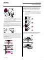
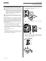
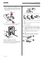
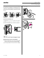
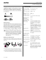
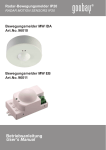
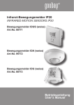
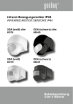
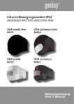
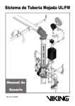
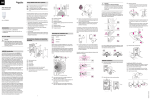
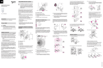
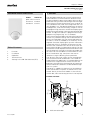
Chapter 5: ARGUS
5.1 ARGUS movement detector, surface-mounted
INSTABUS ARGUS 220 Connect
Art. no. 6315 ..
INSTABUS ARGUS 220 ConnectChapter 5: ARGUSArt. no. 6315 ..Version 03/045.1 ARGUS movement detector, surface-mounted
INSTABUS ARGUS 220 Connect
Colour
polar white
aluminium
dark brazil
1. Function
Article no.
631519
631569
631515
Table of Contents
1.
Function
1
2.
Installation
2
3.
Operation
7
4.
Technical Data
8
5.
Settings in the EIB Tool Software (ETS)
9
The INSTABUS ARGUS 220 Connect (subsequently
called ARGUS) is an EIB movement detector which
can be used both indoors and outdoors due to its IP 55
protection rating. Surface monitoring of 220° for larger
house fronts and areas of the house (max. range of 16
m) is combined with a 360° short-range zone with a radius of approx. 4 m. The operating elements for setting
the brightness, time and sensitivity (range) as well as
the programming area and a red LED for displaying the
programming are located under the cover plate for protection. The physical address is programmed using a
programming magnet (e.g. art. no. 639190).
The universal device enables wall and ceiling mounting
without any additional fittings and can be attached to
corners or fixed pipes with the mounting bracket (art.
no. 5652 ..) which is available as an accessory. The integrated functional display lights up when movement
is detected and thus simplifies the alignment of the
device at the installation site. You can also switch off
the functional display via a parameter setting. The area
of detection can be adapted to the local conditions due
to the horizontally, vertically and axially adjustable sensor head. You can also block unwanted zones or sources of interference (e.g. trees) from the area of
detection using the blanking inserts provided.
The device is fitted with a light sensor whose brightness threshold can be set between 3 and 1000 lux.
Depending on the application, it is also possible to use
the device as a light-sensitive switch or to link the
brightness threshold with the detection of movement.
Several movement detectors can be combined together in a system.
The power is supplied via the bus line. No additional
mains connection is required. As the bus line is connected directly to the terminal block in the wall connection box, a bus connecting terminal is not required.
Product overview:
A
B
C
H
G
F
E
D
A
Version 03/04
Wall connection box
1
Chapter 5: ARGUS
5.1 ARGUS movement detector, surface-mounted
INSTABUS ARGUS 220 Connect
Art. no. 6315 ..
2. Installation
B
Top section
C
Cover plate
D
Sensor head
E
Contact pins
Correct
F
Cable entry for bus line from underneath
Not optimum
G
Cable entry for bus line from behind
Incorrect
H
Terminal block for connecting the bus line and for
locating the contact pins
Explanation of the symbols used
What you need to know about the installation site
¼
Danger due to electrical current!
All work on the device should only be carried
out by qualified electricians. Both the countryspecific regulations and the valid EIB guidelines
should be observed.
A
B
G
F
C
D
E
When selecting a suitable installation site, you should
take numerous standpoints into account so that the
movement detector operates at the optimum level.
The following diagram shows the ranges of the ARGUS. They are based on average temperature conditions at a mounting height of 2.5 m. The range of a
movement detector can fluctuate considerably at variable temperatures.
m
A
Sensitivity controller
B
Time controller
C
Brightness controller
D
Functional display, lights up each time movement is detected
14
E
Brightness sensor
10
F
Programming area for magnet
8
G
Programming LED
6
2,5m
0
0,8m
0
4
12
2
4
6
8
B
A
10 12 14 16m
C
4
2
0
2
4
6
8
10
12
14
4
2
0
2
4
6
8
10 12 14 16m
– A: Inner security zone with an angle of detection of
360° and a radius of approx. 4 m.
– B: Central security zone with an angle of detection
of 220° and an area of detection of approx.
9 m x 18 m.
– C: Outer security zone with an angle of detection of
220° and an area of detection of approx.
16 m x 28 m.
Version 03/04
2
Chapter 5: ARGUS
5.1 ARGUS movement detector, surface-mounted
INSTABUS ARGUS 220 Connect
Art. no. 6315 ..
To avoid the connected load being switched on due to
environmental influences, the ARGUS should if possible be mounted so that it is protected against rain
and direct sunlight. A raindrop running over the lens,
for example, can activate the movement detector.
2
¼
E
D
E
Risk of damage!
If the installation is not carried out correctly, water can penetrate the ARGUS and damage it. Always mount it with the spherical head pointing
downwards.
– D: Select a mounting height between 2 m and 3 m.
For optimum monitoring, we recommend a height
of 2.5 m on a solid and even base.
– E: Maintain a distance of at least 5 m from sources
of optical interference. Use the blanking inserts provided if necessary.
In principle, you should not mount the luminaire underneath the ARGUS. The radiated heat from the luminaire can influence the function of the movement
detector and lead to a permanent lighting circuit under
certain conditions:
OK
OK
F
A minimum distance of 5 m (F) should be maintained
between the luminaire and the movement detector. If
this distance cannot be achieved, you can use the inserts provided to "blank out" the light source from the
area of detection.
If possible, mount the movement detector sideways
to the direction of travel:
If you wish to attach several movement detectors,
mount them so that the detection areas of the individual movement detectors intersect each other.
OK
OK
OK
Version 03/04
3
Chapter 5: ARGUS
5.1 ARGUS movement detector, surface-mounted
INSTABUS ARGUS 220 Connect
Art. no. 6315 ..
Using movement detectors with alarm systems
|
Movement detectors are not suitable for use as
components of an alarm system as defined by
the German insurance industry association VdS
(Verband der Sachversicherer). After a bus voltage failure, the detectors may be triggered independently of movements. This could in turn
trigger the alarm function.
How to install the ARGUS
1 Loosen the two screws and remove the wall connection box from the device.
Movement detectors can trigger false alarms if
| the installation site has been chosen unfavourably.
Movement detectors switch as soon as they detect a
moving heat source. This can be a person, but also
trees, cars or differences in temperature in windows.
In order to avoid false alarms, the chosen installation
site should be such that undesired heat sources cannot be detected. Undesired sources of heat could include the following:
– moving trees, shrubbery etc. with a temperature
that differs from that of their surroundings
– windows where the influence of sunlight and
clouds could cause rapid changes in temperature.
– larger heat sources (e.g. cars), that are detected through windows.
– insects running over the lens.
– small animals
– rooms flooded with light where the light is reflected
on objects (e.g. the floor), which can be the cause
of rapid changes in temperature.
2 Mark the intended drill holes on the mounting surface.
3 If you wish to insert a bus line from the top into the
back of the device, clip the four spacers supplied
onto the wall connection box.
Version 03/04
4
Chapter 5: ARGUS
5.1 ARGUS movement detector, surface-mounted
INSTABUS ARGUS 220 Connect
Art. no. 6315 ..
4 A: Insert the bus line from behind. Slide the rubber
grommet supplied over the stripped bus line.
B: Insert the bus line from underneath. Cut the rubber insert supplied according to the cable thickness
and place it in the wall connection box. Slide the
bus line through.
A
1
B
5 Install the wall connection box in the intended location using the screws and plugs supplied.
2
3
1 Turn the sensor head upwards until it reaches the
stop.
2 Turn the sensor head clockwise until it reaches the
stop.
3 Align the sensor head.
¼
Risk of damage!
If not installed correctly, the device can be damaged by condensation. In the case of sloping
ceilings, mount the device so that the spherical
head points downwards and always at an angle
of 15-90°.
When the spherical head points downwards, water
from condensation could run down the device.
Note
| The protection rating IP 55 cannot be guaranteed if the mounting angle is not 15-90°.
Installing the ARGUS on the ceiling
In order to install the ARGUS on the ceiling, you must
rotate the sensor head. Change the direction of rotation once you have reached the end stops.
Version 03/04
5
Chapter 5: ARGUS
5.1 ARGUS movement detector, surface-mounted
INSTABUS ARGUS 220 Connect
Art. no. 6315 ..
Mounting the ARGUS on corners and fixed pipes
You can mount the ARGUS on inner/outer corners or
fixed pipes using the Merten mounting bracket (accessories, art. no. 5652 91/92/93). You can feed the bus
line to the device from behind through the mounting
bracket.
3 Place the cover plate onto the markings and slide it
downwards.
1
2
Connecting the EIB bus line
1 Strip approx. 14 mm of insulation from the bus lines.
2 Insert the red bus line (+) into the (+) terminal.
3 Insert the black bus line (-) into the (-) terminal.
Bus
+ -
+
-
ARGUS
3
Note
| You can wire the bus line through the two terminals (+) and (–) without any problems arising.
Mounting the top section of the ARGUS
1 Place the top section on the wall connection box
from the front. Ensure that the connecting pins inserted in the top section do not become bent.
2 Fix the top section with the two screws supplied.
Version 03/04
6
Chapter 5: ARGUS
5.1 ARGUS movement detector, surface-mounted
INSTABUS ARGUS 220 Connect
Art. no. 6315 ..
3. Operation
Note
| Depending on the application program, you can
either set the time in the software or on the
time controller.
Putting the ARGUS into operation
The operating elements of the ARGUS are protected
by the cover plate. You can read off the set values
thanks to the position of the arrow shown on the controllers.
1 Slide the plate upwards by approx. 6 mm until you
feel it hit the stop, and then pull it forwards.
1 Set the time to 1 second (left-hand stop).
2 Set the brightness controller to daytime operation
(sun symbol/right-hand stop) or select the setting
"independent of brightness" in ETS.
3 Set the sensitivity to maximum (right-hand stop).
The functional display lights up after each detection of
movement e.g. when you place your hand in front of
the ARGUS.
Setting the ARGUS
¼
2 Load the physical address and the application into
the movement detector using the EIB Tool Software (ETS).
A: When assigning the physical address, guide a
programming magnet (e.g. art. no. 6391 90) over
the programming area.
B: During the assignment, the programming LED
lights up. It is extinguished if the physical address
has been loaded successfully.
Risk of damage!
The sensor head should only be rotated until it
reaches the stop and no further.
To achieve an angle "above" the stop, change the
direction of rotation.
1 Align the sensor head of the movement detector to
the monitored area.
2 Step from the edge into the area of detection and
check whether the ARGUS switches the load and
the functional display.
9˚
12˚ 12˚
24˚
4˚ 29˚
25˚
12˚
25˚
12˚
8,5˚ 8,5˚
Setting the sensitivity
The sensitivity can be infinitely adjusted with the sensitivity controller so that the ARGUS detects movements up to a distance of 16 m.
A
B
Conducting a functional test
Version 03/04
7
Chapter 5: ARGUS
5.1 ARGUS movement detector, surface-mounted
INSTABUS ARGUS 220 Connect
Art. no. 6315 ..
Setting the brightness
4. Technical Data
The brightness threshold can be infinitely adjusted in a
range between approx. 3 lux and 1000 lux. In daytime
operation (sun symbol), the ARGUS switches after
each movement, regardless of the external brightness.
In night operation (moon symbol), it only reacts below
3 lux (darkness).
3 LUX
1000 LUX
Nominal voltage:
Connection to the
bus:
Power consumption:
Area of detection:
Range:
Number of levels:
Number of zones:
Minimum mounting height:
Recommended
mounting height:
Sensitivity:
Light sensor:
Setting the time
This makes it possible to set the overshoot time of the
connected loads. This is the time period from the last
detected movement until the load is switched off. Depending on the ETS application, the overshoot time is
either set in the ETS program (infinitely between
3 seconds and 152 seconds) or directly on the ARGUS
(six steps of approx. 1 second to approx. 8 minutes).
Time:
Programming:
Once the load has been switched on, the set
| brightness threshold is ignored. Depending on
the settings in ETS, each registered movement
can reset the overshoot time. If the movement
detector no longer switches off, it is probably
because it is continually detecting new movements and is thus always extending the
overshoot time.
Masking out individual areas
Using the four inserts supplied, you can shield unwanted zones and sources of interference from the area of
detection.
A
1
2
Display elements:
DC 24 V (+6 V / -4 V)
via the terminal
approx. 7 mA
220°
max. 16 m
7
112 with 448 switching segments
1.7 m
2.5 m
infinitely adjustable externally
infinitely adjustable externally,
from approx. 3 lux to approx.
1000 lux
infinitely adjustable in the software from 3 seconds to 152 seconds or adjustable externally in
6 levels from approx. 1 second
to approx. 8 minutes
magnet-sensitive sensor for the
assignment of the physical
address
red LED for checking the programming, red LED for functional display
Possible settings
for the sensor
head:
Wall mounting:
9° upwards, 24° downwards,
12° right/left, ± 12° axially
Ceiling mounting: 4° upwards, 29° downwards,
25° right/left, ± 8.5° axially
Type of protection: IP 55 at an angle of inclination
from 15° to 90°
Ambient tempera- -25°C to +55°C
ture:
EC guidelines:
low voltage guideline 73/23/
EEC, EMC guideline 89/336/
EEC
Initialisation:
Due to the limitation of the telegram rate, a telegram cannot be
generated until at least 17 sec
after the initialisation.
1 Place the inserts exactly on those areas of the sensor head which should be masked from detection.
2 Ensure that the brightness sensor (A) is not covered as the sensitivity to light is otherwise reduced.
Version 03/04
8
Chapter 5: ARGUS
5.1 ARGUS movement detector, surface-mounted
INSTABUS ARGUS 220 Connect
Art. no. 6315 ..
5. Settings in the EIB Tool Software (ETS)
Application overview
Selection in the product database
Application overview
Manufacturer:
Product family:
The following applications can be selected for operation with the ARGUS detector:
Merten
3.1
Movement detector
ARGUS
Product type:
3.1.16 Outdoor movement detector
Program name: ARGUS with time function 1320/1
ARGUS cyclical 1311/2
ARGUS 4-gang function 1312/2
ARGUS 3-gang function 1313/1
ARGUS alarm 1314/2
Media type:
Twisted Pair
Product name: INSTABUS ARGUS 220 Connect
Order number: 6315 19 (polar white)
6315 15 (dark brazil)
6315 69 (aluminium)
|
To guarantee the full functionality of the applications under ETS2, the ETS2 program from version 1.2 onwards and Service Release A or higher
should be used. If you have any queries, please
contact the Merten InfoLine.
Application
Vers. Function
ARGUS with timing
function 1320/1
1
Movement-dependent switching and
switching dependent on/independent
of brightness
Brightness-dependent switching
Integrated staircase lighting timer
Lockable via the bus
Can be switched via the bus (trigger
object)
Setting the safety interval
Function LED
ARGUS cyclical 1311/ 2
2
Cyclical sending independent of movement and cyclical sending dependent on/independent of brightness
Brightness-dependent switching
Lockable via the bus
Setting the safety interval
Function LED
ARGUS 4-gang func- 2
tion 1312/2
3 x movement-dependent switching
and switching dependent on/independent of brightness (1 bit)
1 x movement-dependent value sending and value sending dependent on/
independent of brightness (1 byte)
4 x lockable via the bus
Setting the safety interval
Function LED
ARGUS 3-gang func- 1
tion 1313/1
3 x switching (1 bit) or value sending
(1 byte), movement-dependent and
dependent on/independent of brightness
3 x lockable via the bus
Can be switched via the bus (trigger
object)
Setting the safety interval
Function LED
ARGUS alarm 1314/2 2
1 x cyclical switching for alarm function, dependent on/independent of
brightness (reduced sensitivity) (Block
A)
1 x staircase lighting function, dependent on/independent of brightness
(Block B)
Locking function can be selected for
Block A, Block B, Block A+B
Setting the safety interval
Function LED
Version 03/04
9