1
Service Manual
iR2030/2025/2022/2018 Series
Aug 8 2007
Application
This manual has been issued by Canon Inc. for qualified persons to learn technical theory, installation, maintenance, and repair
of products. This manual covers all localities where the products are sold. For this reason, there may be information in this
manual that does not apply to your locality.
Corrections
This manual may contain technical inaccuracies or typographical errors due to improvements or changes in products. When
changes occur in applicable products or in the contents of this manual, Canon will release technical information as the need
arises. In the event of major changes in the contents of this manual over a long or short period, Canon will issue a new edition
of this manual.
The following paragraph does not apply to any countries where such provisions are inconsistent with local law.
Trademarks
The product names and company names used in this manual are the registered trademarks of the individual companies.
Copyright
This manual is copyrighted with all rights reserved. Under the copyright laws, this manual may not be copied, reproduced or
translated into another language, in whole or in part, without the written consent of Canon Inc.
COPYRIGHT © 2001 CANON INC.
Printed in Japan
Caution
Use of this manual should be strictly supervised to avoid disclosure of confidential information.
Introduction
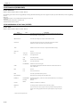
Symbols Used
This documentation uses the following symbols to indicate special information:
Symbol
Description
Indicates an item of a non-specific nature, possibly classified as Note, Caution, or Warning.
Indicates an item requiring care to avoid electric shocks.
Indicates an item requiring care to avoid combustion (fire).
Indicates an item prohibiting disassembly to avoid electric shocks or problems.
Indicates an item requiring disconnection of the power plug from the electric outlet.
Indicates an item intended to provide notes assisting the understanding of the topic in question.
Memo
Indicates an item of reference assisting the understanding of the topic in question.
REF.
Provides a description of a service mode.
Provides a description of the nature of an error indication.
Introduction
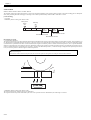
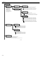
The following rules apply throughout this Service Manual:
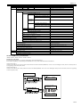
1. Each chapter contains sections explaining the purpose of specific functions and the relationship between electrical and mechanical systems with reference to the timing of operation.
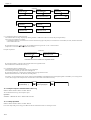
In the diagrams,
represents the path of mechanical drive; where a signal name accompanies the symbol , the arrow
indicates the
direction of the electric signal.
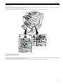
The expression "turn on the power" means flipping on the power switch, closing the front door, and closing the delivery unit door, which results in
supplying the machine with power.
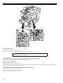
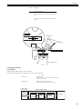
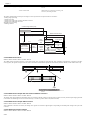
2. In the digital circuits, '1'is used to indicate that the voltage level of a given signal is "High", while '0' is used to indicate "Low".(The voltage value, however, differs from circuit to circuit.) In addition, the asterisk (*) as in "DRMD*" indicates that the DRMD signal goes on when '0'.
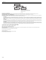
In practically all cases, the internal mechanisms of a microprocessor cannot be checked in the field. Therefore, the operations of the microprocessors
used in the machines are not discussed: they are explained in terms of from sensors to the input of the DC controller PCB and from the output of the
DC controller PCB to the loads.
The descriptions in this Service Manual are subject to change without notice for product improvement or other purposes, and major changes will be communicated in the form of Service Information bulletins.
All service persons are expected to have a good understanding of the contents of this Service Manual and all relevant Service Information bulletins and be
able to identify and isolate faults in the machine."
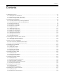
Contents
Contents
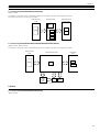
Chapter 1 Introduction
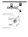
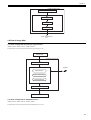
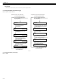
1.1 System Construction ..................................................................................................................................1- 1
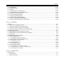
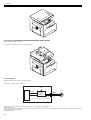
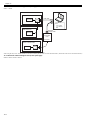
1.1.1 Pickup/Delivery/Original Handling Accessories System Configuration (iR2018)..................................................... 1- 1
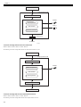
1.1.2 Pickup/Delivery/Original Handling Accessories System Configuration (iR2018i) .................................................... 1- 2
1.1.3 Pickup/ Delivery /Original Handling Accessories System Configuration (iR2022/iR2022N/iR2025/iR2030) ........... 1- 3
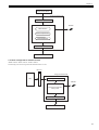
1.1.4 Pickup/Delivery/Original Handling Accessories System Configuration (iR2022i/iR2022K/iR2025i/iR2030i)........... 1- 4
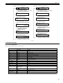
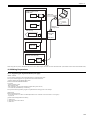
1.1.5 Reader Heater/Cassette Heater System Configuration (iR2018/iR2022/iR2022N) ................................................ 1- 5
1.1.6 Reader Heater/Cassette Heater System Configuration (iR2018i) ........................................................................... 1- 6
1.1.7 Reader Heater/Cassette Heater System Configuration (iR2022K/iR2022i/iR2025/iR2025i/iR2030/iR2030i) ......... 1- 7
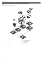
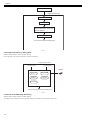
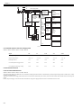
1.1.8 Printing/Transmitting Accessories System Configuration (iR2018/ir2022/iR2022N) ............................................... 1- 8
1.1.9 Printing/Transmitting Accessories System Configuration (iR2018i/iR2022i/iR2022K/iR2025/iR2025i/iR2030/iR2030i)
1- 9
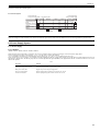
1.1.10 Functions of the Printing/Transmission Functions (iR2018/iR2022/iR2022N) ..................................................... 1- 10
1.1.11 Functions of the Printing/Transmission Functions (iR2018i/iR2022i/iR2022K/iR2025/iR2025i/IR2030/iR2030i) 1- 10
1.2 Product Specifications ..............................................................................................................................1- 10
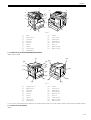
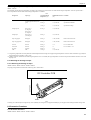
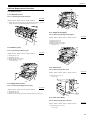
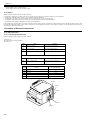
1.2.1 Names of Parts...................................................................................................................................................... 1- 10
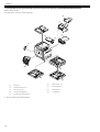
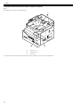
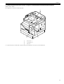
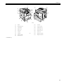
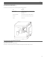
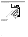
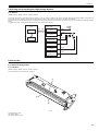
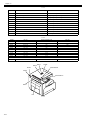
1.2.1.1 External View (iR2030i/iR2025i/iR2022i) ............................................................................................................................... 1- 10
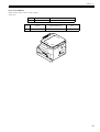
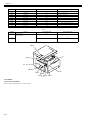
1.2.1.2 External View (iR2020/iR2020N/iR2030/iR2025) .................................................................................................................. 1- 11
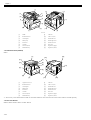
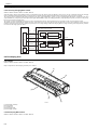
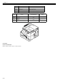
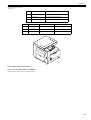
1.2.1.3 External View (iR2018i) ......................................................................................................................................................... 1- 11
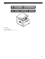
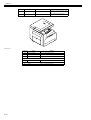
1.2.1.4 External View (iR2018) .......................................................................................................................................................... 1- 12
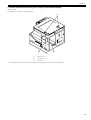
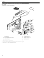
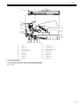
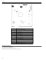
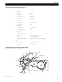
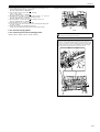
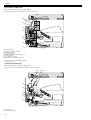
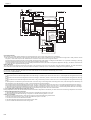
1.2.1.5 Cross-Section ........................................................................................................................................................................ 1- 12
1.2.2 Using the Machine................................................................................................................................................. 1- 13
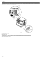
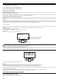
1.2.2.1 Turning On the Power Switch (iR2018/iR2022/iR2022N) ...................................................................................................... 1- 13
1.2.2.2 Turning On the Power Switch (iR2018i/iR2020i/iR2020K/iR2025/iR2025i/iR2030/iR2030i) ................................................. 1- 14
1.2.2.3 When Turning Off the Main Power Switch (iR2018/iR2022/iR2022N)................................................................................... 1- 15
1.2.2.4 When Turning Off the Main Power Switch (iR2018i/iR2022i/iR2022K/iR2025/iR2025i/iR2030/iR2030i) .............................. 1- 16
1.2.2.5 Control Panel ......................................................................................................................................................................... 1- 17
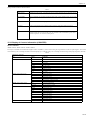
1.2.3 User Mode Items ................................................................................................................................................... 1- 18
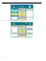
1.2.3.1 Common Settings (iR2030i/iR2030/iR2025i/iR2025/iR2022i/iR2018i) .................................................................................. 1- 18
1.2.3.2 Timer Settings (iR2030i/iR2030/iR2025i/iR2025/iR2022i/iR2018i)........................................................................................ 1- 19
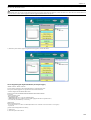
1.2.3.3 Adjustment/Cleaning (iR2030i/iR2030/iR2025i/iR2025/iR2022i/iR2018i).............................................................................. 1- 19
1.2.3.4 Report Settings (iR2030i/iR2030/iR2025i/iR2025/iR2022i/iR2018i) ...................................................................................... 1- 19
1.2.3.5 System Settings (iR2030i/iR2030/iR2025i/iR2025/iR2022i/iR2018i) ..................................................................................... 1- 20
1.2.3.6 Copy Settings (iR2030i/iR2030/iR2025i/iR2025/iR2022i/iR2018i)......................................................................................... 1- 21
1.2.3.7 Communication Settings (iR2030i/iR2030/iR2025i/iR2025/iR2022i/iR2018i) ........................................................................ 1- 21
1.2.3.8 Printer Settings (iR2030i/iR2030/iR2025i/iR2025/iR2022i/iR2018i) ...................................................................................... 1- 22
1.2.3.9 Address Book Settings (iR2030i/iR2030/iR2025i/iR2025/iR2022i/iR2018i)........................................................................... 1- 23
1.2.3.10 Recommended setting of system management information ................................................................................................ 1- 23
1.2.3.11 The Reference Information of the Department ID Management .......................................................................................... 1- 23
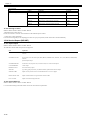
1.2.4 Maintenance by the User....................................................................................................................................... 1- 23
1.2.4.1 User Maintenance Items ........................................................................................................................................................ 1- 23
1.2.4.2 Cleaning (LCD type) .............................................................................................................................................................. 1- 24
1.2.4.3 Cleaning (Touch panel type).................................................................................................................................................. 1- 25
1.2.5 Safety .................................................................................................................................................................... 1- 26
1.2.5.1 Safety of the Laser Light ........................................................................................................................................................ 1- 26
1.2.5.2 CDRH Regulations................................................................................................................................................................. 1- 26
1.2.5.3 Handling the Laser Unit ........................................................................................................................................................ 1- 26
1.2.5.4 Handling the Laser Unit ......................................................................................................................................................... 1- 27
1.2.5.5 Safety of Toner ...................................................................................................................................................................... 1- 28
1.2.5.6 Point to Note about Fire ......................................................................................................................................................... 1- 28
1.2.5.7 Cautions as to the replacement and disposal of lithium battery............................................................................................. 1- 28
1.2.6 Product Specifications ........................................................................................................................................... 1- 29
1.2.6.1 Product Specifications ........................................................................................................................................................... 1- 29
Contents
1.2.7 Function List...........................................................................................................................................................1- 30
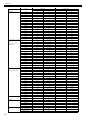
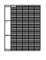
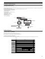
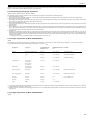
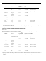
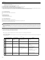
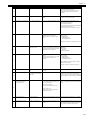
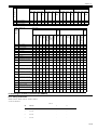
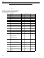
1.2.7.1 Printing Speed (iR2030/iR2030i) ........................................................................................................................................... 1- 30
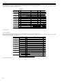
1.2.7.2 Printing Speed (iR2025/iR2025i) ........................................................................................................................................... 1- 31
1.2.7.3 Printing Speed (iR2022/iR2022i/iR2022K/iR2022N)) ............................................................................................................ 1- 32
1.2.7.4 Printing Speed (iR2018/iR2018i/iR2018N) ............................................................................................................................ 1- 34
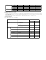
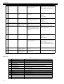
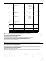
1.2.7.5 Types of Paper....................................................................................................................................................................... 1- 35
Chapter 2 Installation
2.1 Making Pre-Checks .................................................................................................................................... 2- 1
2.1.1 Selecting the Site of Installation...............................................................................................................................2- 1
2.1.2 Before Starting the Work (230V CENV)...................................................................................................................2- 1
2.1.3 Before Starting the Work (230V CENV)...................................................................................................................2- 4
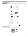
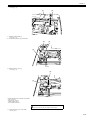
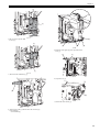
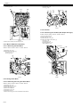
2.2 Unpacking and Installation ......................................................................................................................... 2- 6
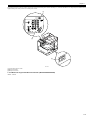
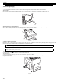
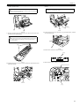
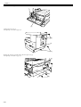
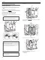
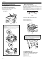
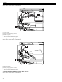
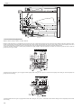
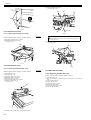
2.2.1 Unpacking and Removing the Packaging Materials ................................................................................................2- 6
2.2.2 Unpacking and Removing the Packaging Materials ................................................................................................2- 6
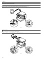
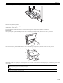
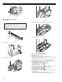
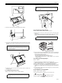
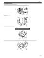
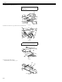
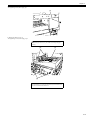
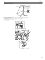
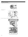
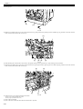
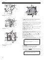
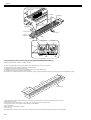
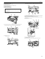
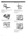
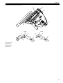
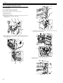
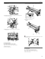
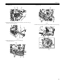
2.2.3 Installing the Drum Unit............................................................................................................................................2- 6
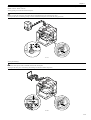
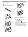
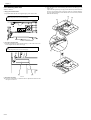
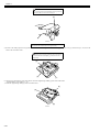
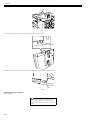
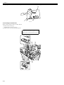
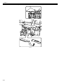
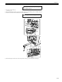
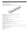
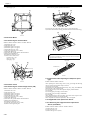
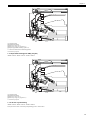
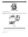
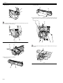
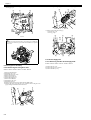
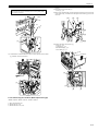
2.2.4 Installing the Toner Bottle ........................................................................................................................................2- 8
2.2.5 Installing the Toner Bottle ........................................................................................................................................2- 9
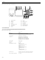
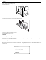
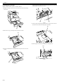
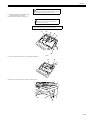
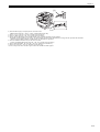
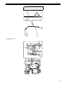
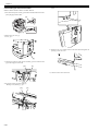
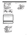
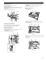
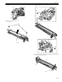
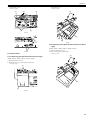
2.2.6 Setting the Cassettes.............................................................................................................................................2- 10
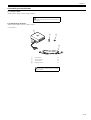
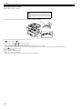
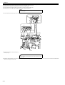
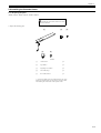
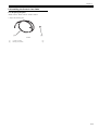
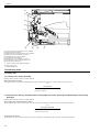
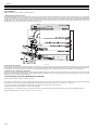
2.2.7 Attaching the Ferrite Core......................................................................................................................................2- 11
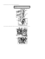
2.2.8 Checking the Image Quality...................................................................................................................................2- 11
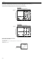
2.2.9 Setting the Country/Region....................................................................................................................................2- 11
2.2.10 Setting the Country/Region ..................................................................................................................................2- 11
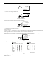
2.2.11 Setting the Date and Time ...................................................................................................................................2- 12
2.2.12 Setting the Date and Time ...................................................................................................................................2- 13
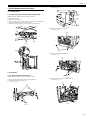
2.2.13 Attaching Other Parts...........................................................................................................................................2- 14
2.3 Checking the Connection to the Network ................................................................................................. 2- 15
2.3.1 Checking the Network Connection.........................................................................................................................2- 15
2.3.2 Checking the Network Connection.........................................................................................................................2- 16
2.4 Flow of Accessory Installation .................................................................................................................. 2- 17
2.4.1 Flow of Accessary Installation (230V CENV).........................................................................................................2- 17
2.4.2 Flow of Accessary Installation (230V CENV).........................................................................................................2- 18
2.5 Installing the Card Reader........................................................................................................................ 2- 19
2.5.1 Points to Note ........................................................................................................................................................2- 19
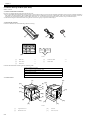
2.5.2 Checking the Contents...........................................................................................................................................2- 19
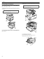
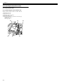
2.5.3 Installation Procedure ............................................................................................................................................2- 21
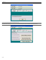
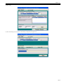
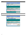
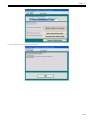
2.5.4 Registering the Card IDs........................................................................................................................................2- 26
2.5.5 Registering the Card IDs........................................................................................................................................2- 28
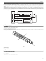
2.6 Installing the Heater PCB ......................................................................................................................... 2- 29
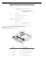
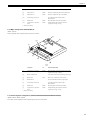
2.6.1 Preparing the parts ................................................................................................................................................2- 29
2.6.2 Preparing the Host Machine ..................................................................................................................................2- 29
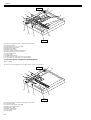
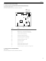
2.6.3 Installing the Heater PCB.......................................................................................................................................2- 32
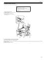
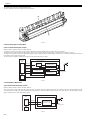
2.7 Installing the Reader Heater..................................................................................................................... 2- 35
2.7.1 Preparing the parts ................................................................................................................................................2- 35
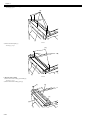
2.7.2 Installing the Reader Heater Harness....................................................................................................................2- 36
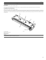
2.7.3 Removing Reader Components.............................................................................................................................2- 41
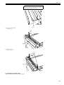
2.7.4 Removing Parts at the Left of the Reader..............................................................................................................2- 41
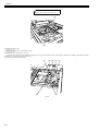
2.7.5 Installing the Reader Heater ..................................................................................................................................2- 43
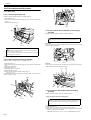
2.8 Installing the Cassette Heater .................................................................................................................. 2- 47
2.8.1 Preparing the parts ................................................................................................................................................2- 47
2.8.2 Installing the Cassette Heater................................................................................................................................2- 48
2.9 Installing the Control Card Cable ............................................................................................................. 2- 51
2.9.1 Preparing the parts ................................................................................................................................................2- 51
2.9.2 Installing the Control Card Cable ...........................................................................................................................2- 52
Contents
Chapter 3 Main Controller
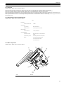
3.1 Construction ...............................................................................................................................................3- 1
3.1.1 Construction and Mechanisms ................................................................................................................................ 3- 1
3.2 Construction of the Electrical Circuitry........................................................................................................3- 1
3.2.1 Image Processor PCB ............................................................................................................................................. 3- 1
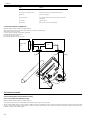
3.3 Image Processing .......................................................................................................................................3- 2
3.3.1 Overview of the Image Flow .................................................................................................................................... 3- 2
3.3.2 Construction of the Image Processing Module........................................................................................................ 3- 3
3.3.3 Reader Unit Input Image Processing....................................................................................................................... 3- 3
3.3.4 Compressio/ Extesion/ Editing Block...................................................................................................................... 3- 4
3.3.5 Printer unit Output Image Processing...................................................................................................................... 3- 4
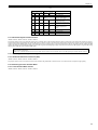
3.4 Flow of Image Data ....................................................................................................................................3- 5
3.4.1 Flow of Image Data According to Copy Functions .................................................................................................. 3- 5
3.4.2 Flow of Image Data for the SEND Function ............................................................................................................ 3- 5
3.4.3 Flow of Image Data for the Fax Transmission......................................................................................................... 3- 6
3.4.4 Flow of Image Data for the Fax Reception Function ............................................................................................... 3- 6
3.4.5 Flow of Image Data for the PDL Function ............................................................................................................... 3- 7
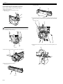
3.5 Parts Replacement Procedure ...................................................................................................................3- 8
3.5.1 Main Controller PCB................................................................................................................................................ 3- 8
3.5.1.1 Preparation for Removing the Image Processor PCB ............................................................................................................. 3- 8
3.5.1.2 Removing the Image Processor PCB ...................................................................................................................................... 3- 8
3.5.1.3 Procedure after Replacing the Image Processor PCB........................................................................................................... 3- 10
3.5.2 SDRAM.................................................................................................................................................................. 3- 10
3.5.2.1 Preparation for Removing the SDRAM .................................................................................................................................. 3- 10
3.5.2.2 Removing the SDRAM........................................................................................................................................................... 3- 11
Chapter 4 Original Exposure System
4.1 Construction ...............................................................................................................................................4- 1
4.1.1 Specifications, Control Methods, and Functions (iR2030i/iR2030/iR2025i/iR2025/iR2022i/iR2022) ...................... 4- 1
4.1.2 Specifications, Control Methods, and Functions (iR2018i/iR2018) ......................................................................... 4- 1
4.1.3 Major Components (iR2030i/iR2030/iR2025i/iR2025/iR2022i/iR2022) ................................................................... 4- 2
4.1.4 Major Components (iR2018i/iR2018) ...................................................................................................................... 4- 3
4.1.5 Control System Configuration (iR2030i/iR2030/iR2025i/iR2025/iR2022i/iR2022) .................................................. 4- 3
4.1.6 Control System Configuration (iR2018i/iR2018)...................................................................................................... 4- 4
4.1.7 Reader Controller PCB (iR2030i/iR2030/iR2025i/iR2025/iR2022i/iR2022)............................................................. 4- 5
4.1.8 Reader Controller PCB (iR2018i/iR2018)................................................................................................................ 4- 5
4.2 Basic Sequence..........................................................................................................................................4- 6
4.2.1 Basic Sequence at Power-on .................................................................................................................................. 4- 6
4.2.2 Basic Sequence after Depression of Start Key (Book mode, One Sheet of original) .............................................. 4- 7
4.2.3 Basic Sequence after Depression of Start Key (ADF Mode, One Sheet of Original) .............................................. 4- 7
4.3 Various Control ...........................................................................................................................................4- 8
4.3.1 Controlling the Scanner Drive System..................................................................................................................... 4- 8
4.3.1.1 Outline...................................................................................................................................................................................... 4- 8
4.3.1.2 Reader Motor Control .............................................................................................................................................................. 4- 9
4.3.2 Contact Image Sensor (CIS) ................................................................................................................................... 4- 9
4.3.2.1 Outline...................................................................................................................................................................................... 4- 9
4.3.2.2 Analog Control Performed by the CIS (iR2022i/iR2022/iR2018i/iR2018) .............................................................................. 4- 10
4.3.2.3 Analog Control Performed by the CIS (iR2030i/iR2030/iR2025i/iR2025/iR2022i/iR2022) .................................................... 4- 11
4.3.3 Enlargement/Reduction ......................................................................................................................................... 4- 11
4.3.3.1 Magnification Change in Vertical Scan Direction ................................................................................................................... 4- 11
4.3.3.2 Magnification Change in Horizontal Scan Direction............................................................................................................... 4- 11
4.3.4 Detecting the Size of Originals .............................................................................................................................. 4- 11
4.3.4.1 Outline.................................................................................................................................................................................... 4- 11
4.3.4.2 Outline of Original Size Detection .......................................................................................................................................... 4- 12
4.3.5 Dirt Sensor Control ................................................................................................................................................ 4- 13
Contents
4.3.5.1 Outline.................................................................................................................................................................................... 4- 13
4.3.6 Image Processing ..................................................................................................................................................4- 15
4.3.6.1 Outline.................................................................................................................................................................................... 4- 15
4.3.6.2 CMOS Sensor Drive .............................................................................................................................................................. 4- 16
4.3.6.3 CMOS Sensor Output Gain Correction and Offset Correction............................................................................................... 4- 16
4.3.6.4 CMOS Sensor Output A/D Conversion.................................................................................................................................. 4- 16
4.3.6.5 Shading Correction (Outline) ................................................................................................................................................ 4- 16
4.3.6.6 Shading Adjustment............................................................................................................................................................... 4- 17
4.3.6.7 Shading Correction ................................................................................................................................................................ 4- 17
4.4 Parts Replacement Procedure ................................................................................................................. 4- 18
4.4.1 Copyboard glass ....................................................................................................................................................4- 18
4.4.1.1 Removing the Copyboard glass............................................................................................................................................. 4- 18
4.4.1.2 Procedure after Replacing the Copyboard Glass (Model equipped with ADF)...................................................................... 4- 18
4.4.1.3 Removing the ADF Reading Glass ........................................................................................................................................ 4- 18
4.4.2 Reader Controller PCB ..........................................................................................................................................4- 18
4.4.2.1 Removing the Reader Controller PCB ................................................................................................................................... 4- 18
4.4.3 Scanner Motor .......................................................................................................................................................4- 20
4.4.3.1 Removing the Scanner Motor ................................................................................................................................................ 4- 20
4.4.4 Contact sensor.......................................................................................................................................................4- 20
4.4.4.1 Removing the Contact Image Sensor (CIS)........................................................................................................................... 4- 20
4.4.4.2 Procedure after Replacing the CIS(Touch panel type) .......................................................................................................... 4- 20
4.4.5 Copyboard Cover Open/Close Sensor ..................................................................................................................4- 20
4.4.5.1 Removing the Copyboard Cover Open/Close Sensor (Front/Rear)....................................................................................... 4- 20
4.4.6 Contact Sensor HP Sensor....................................................................................................................................4- 21
4.4.6.1 Removing the Contact Sensor HP Sensor............................................................................................................................. 4- 21
4.4.7 Original Size Sensor ..............................................................................................................................................4- 21
4.4.7.1 Removing the Original Sensor (Vertical Scan Direction) ....................................................................................................... 4- 21
4.4.7.2 Removing the Original Sensor (Horizontal Scan Direction) ................................................................................................... 4- 22
4.4.8 Reader Heater (option) ..........................................................................................................................................4- 22
4.4.8.1 Removing the Reader Heater (Right) .................................................................................................................................... 4- 22
4.4.8.2 Removing the Reader Heater (Left)....................................................................................................................................... 4- 22
Chapter 5 Laser Exposure
5.1 Construction ............................................................................................................................................... 5- 1
5.1.1 Overview ..................................................................................................................................................................5- 1
5.1.2 Specifications and Control Mechanism....................................................................................................................5- 1
5.1.3 Main Components....................................................................................................................................................5- 1
5.1.4 Control System Configuration ..................................................................................................................................5- 2
5.2 Various Controls ......................................................................................................................................... 5- 2
5.2.1 Controlling the Laser Activation Timing ...................................................................................................................5- 2
5.2.1.1 Laser Emission ON/OFF Control ............................................................................................................................................. 5- 2
5.2.1.2 Horizontal Synchronization Control.......................................................................................................................................... 5- 3
5.2.2 Controlling the Intensity of Laser Light.....................................................................................................................5- 3
5.2.2.1 Automatic Photocurrent Control (APC) .................................................................................................................................... 5- 3
5.2.3 Controlling the Laser Scanner Motor .......................................................................................................................5- 3
5.2.3.1 Laser Scanner Motor Control................................................................................................................................................... 5- 3
5.2.4 Controlling the Laser Shutter ...................................................................................................................................5- 4
5.2.4.1 Laser Shutter Control............................................................................................................................................................... 5- 4
5.3 Parts Replacement Procedure ................................................................................................................... 5- 6
5.3.1 Laser Scanner Unit ..................................................................................................................................................5- 6
5.3.1.1 Removing the Laser Scanner Unit ........................................................................................................................................... 5- 6
Chapter 6 Image Formation
6.1 Construction ............................................................................................................................................... 6- 1
6.1.1 Specifications of Image Formation System..............................................................................................................6- 1
6.1.2 Major Components of Image Formation System .....................................................................................................6- 1
Contents
6.2 Image Formation Process ..........................................................................................................................6- 3
6.2.1 Image Formation Process ....................................................................................................................................... 6- 3
6.3 Basic Sequence..........................................................................................................................................6- 3
6.3.1 Basic Sequence of Operation.................................................................................................................................. 6- 3
6.4 Driving and Controlling the High-Voltage System.......................................................................................6- 5
6.4.1 Outline ..................................................................................................................................................................... 6- 5
6.5 Drum Unit ...................................................................................................................................................6- 5
6.5.1 Outline of the Drum Unit .......................................................................................................................................... 6- 5
6.5.1.1 Outline...................................................................................................................................................................................... 6- 5
6.5.2 Charging Mechanism............................................................................................................................................... 6- 6
6.5.2.1 Primary Charging Bias Control ................................................................................................................................................ 6- 6
6.6 Developing Unit ..........................................................................................................................................6- 6
6.6.1 Outline ..................................................................................................................................................................... 6- 6
6.6.2 Developing Bias Control .......................................................................................................................................... 6- 6
6.7 Toner Container..........................................................................................................................................6- 7
6.7.1 Outline ..................................................................................................................................................................... 6- 7
6.8 Transfer Unit ...............................................................................................................................................6- 7
6.8.1 Outline of the Transfer Unit ..................................................................................................................................... 6- 7
6.8.1.1 Outline...................................................................................................................................................................................... 6- 7
6.8.2 Controlling the Transfer Bias ................................................................................................................................... 6- 8
6.8.2.1 Transfer Roller Bias Control..................................................................................................................................................... 6- 8
6.8.3 Separation Mechanism............................................................................................................................................ 6- 8
6.8.3.1 Static Eliminator Bias Control .................................................................................................................................................. 6- 8
6.9 Photosensitive Drum Cleaning ...................................................................................................................6- 9
6.9.1 Outline ..................................................................................................................................................................... 6- 9
6.9.2 Waste Toner Full Detection ..................................................................................................................................... 6- 9
6.10 Parts Replacement Procedure................................................................................................................6- 10
6.10.1 Drum Unit............................................................................................................................................................. 6- 10
6.10.1.1 Removing the Drum Unit...................................................................................................................................................... 6- 10
6.10.2 Developing Assembly .......................................................................................................................................... 6- 10
6.10.2.1 Removing the Developing Assembly ................................................................................................................................... 6- 10
6.10.2.2 Precautions about Installation of Developing Assembly ..................................................................................................... 6- 10
6.10.2.3 Procedure after Replacing the Developing Assembly.......................................................................................................... 6- 10
6.10.3 Transfer Charging Roller ..................................................................................................................................... 6- 11
6.10.3.1 Removing the Transfer Charging Roller............................................................................................................................... 6- 11
Chapter 7 Pickup/Feeding System
7.1 Construction ...............................................................................................................................................7- 1
7.1.1 Specifications/Configuration/Operation Methods .................................................................................................... 7- 1
7.1.2 Locations of Main Units ........................................................................................................................................... 7- 2
7.1.3 Roller Layout Drawing ............................................................................................................................................. 7- 2
7.1.4 Paper Path Drawing (Printer on its own) ................................................................................................................. 7- 3
7.1.5 Paper Path Drawing (Finisher-U2) .......................................................................................................................... 7- 3
7.1.6 Paper Path Drawing (Duplex Unit-B1/Finisher-U2) ................................................................................................. 7- 4
7.1.7 Paper Path Drawing (Duplex Unit-B1)..................................................................................................................... 7- 4
7.1.8 Paper Path Drawing (Duplex-B1/Inner 2Way Tray-E2) ........................................................................................... 7- 4
7.1.9 Paper Path Drawing(Inner 2Way Tray-E2).............................................................................................................. 7- 5
7.1.10 Sensor Layout Drawing ......................................................................................................................................... 7- 5
7.2 Detecting Jams ...........................................................................................................................................7- 6
7.2.1 Delay Jams.............................................................................................................................................................. 7- 6
7.2.1.1 Delay Jam in Pickup Assembly................................................................................................................................................ 7- 6
7.2.1.2 Delay Jam in Delivery Assembly (Paper Leading Edge Jam at First Delivery Sensor/Wound Paper Jam at Fixing Assembly) 76
7.2.2 Stationary Jams....................................................................................................................................................... 7- 7
7.2.2.1 Stationary Jam in Pickup Assembly......................................................................................................................................... 7- 7
7.2.2.2 Stationary Jam in Delivery Assembly (Paper Trailing Edge Stationary Jam at First Delivery Sensor/Stationary Jam at First
Contents
Delivery Sensor)............................................................................................................................................................................. 7- 7
7.2.3 Other Jams ..............................................................................................................................................................7- 7
7.2.3.1 Door Open Jam........................................................................................................................................................................ 7- 7
7.3 Cassette Pick-Up Unit ................................................................................................................................ 7- 7
7.3.1 Overview ..................................................................................................................................................................7- 7
7.3.2 Cassette Pickup Operation ......................................................................................................................................7- 8
7.3.3 Cassette Paper Size Detection ................................................................................................................................7- 9
7.4 Manual Feed Pickup Unit ......................................................................................................................... 7- 10
7.4.1 Overview ................................................................................................................................................................7- 10
7.4.2 Post-pickup Control after Multi Manual Feed Pickup .............................................................................................7- 10
7.5 Parts Replacement Procedure ................................................................................................................. 7- 11
7.5.1 Pickup Roller..........................................................................................................................................................7- 11
7.5.1.1 Removing the Cassette Paper Pickup Roller......................................................................................................................... 7- 11
7.5.2 Cassette.................................................................................................................................................................7- 11
7.5.2.1 Removing the Cassette Unit .................................................................................................................................................. 7- 11
7.5.3 Cassette Pickup Assembly ....................................................................................................................................7- 12
7.5.3.1 Removing the Cassette Pickup Assembly ............................................................................................................................. 7- 12
7.5.4 Cassette Size Sensor ............................................................................................................................................7- 12
7.5.4.1 Removing the Paper Size Detection Switches....................................................................................................................... 7- 12
7.5.5 Cassette Retry Paper Sensor ................................................................................................................................7- 12
7.5.5.1 Removing the Retry Sensor................................................................................................................................................... 7- 12
7.5.6 Cassette Paper Sensor..........................................................................................................................................7- 12
7.5.6.1 Removing the Cassette Paper Presence/Absence Sensor ................................................................................................... 7- 12
7.5.7 Cassette Pickup Solenoid ......................................................................................................................................7- 13
7.5.7.1 Removing the Cassette Pickup Solenoid............................................................................................................................... 7- 13
7.5.8 Manual Pickup Roller .............................................................................................................................................7- 13
7.5.8.1 Removing the Multifeeder Pickup Roller................................................................................................................................ 7- 13
7.5.9 Manual Feed Tray paper sensor............................................................................................................................7- 13
7.5.9.1 Removing the Multifeeder Paper Presence/Absence Sensor................................................................................................ 7- 13
7.5.10 Manual Feed Pickup Solenoid .............................................................................................................................7- 14
7.5.10.1 Removing the Multifeeder Pickup Solenoid ......................................................................................................................... 7- 14
7.5.11 Registration Roller................................................................................................................................................7- 15
7.5.11.1 Removing the Registration Roller ........................................................................................................................................ 7- 15
7.5.12 Registration Clutch...............................................................................................................................................7- 15
7.5.12.1 Removing the Registration Clutch........................................................................................................................................ 7- 15
7.5.13 Separation Roller .................................................................................................................................................7- 15
7.5.13.1 Removing the Feed and Separation Rollers ........................................................................................................................ 7- 15
7.5.14 Separation Pad ....................................................................................................................................................7- 16
7.5.14.1 Removing the Separation Pad ............................................................................................................................................. 7- 16
Chapter 8 Fixing System
8.1 Construction ............................................................................................................................................... 8- 1
8.1.1 Specifications, Control Mechanisms and Functions ................................................................................................8- 1
8.1.2 Major Components...................................................................................................................................................8- 1
8.2 Various Control Mechanisms ..................................................................................................................... 8- 2
8.2.1 Controlling the Speed of the Fixing Film ..................................................................................................................8- 2
8.2.1.1 Controlling the Fixing Film Speed ............................................................................................................................................ 8- 2
8.2.2 Controlling the Fixing Film Temperature..................................................................................................................8- 2
8.2.2.1 Outline...................................................................................................................................................................................... 8- 2
8.2.2.2 Controlling the Fixing Film Temperature.................................................................................................................................. 8- 3
8.2.2.3 Target Temperatures by Mode (iR2030/iR2030i) .................................................................................................................... 8- 3
8.2.2.4 Target Temperatures by Mode (iR2025/iR2025i) .................................................................................................................... 8- 3
8.2.2.5 Target Temperatures by Mode (iR2022/iR2022i/iR2022K/iR2022N)....................................................................................... 8- 4
8.2.2.6 Target Temperatures by Mode (iR2018/iR2018i/iR2018N) ..................................................................................................... 8- 5
8.2.3 Detecting the Passage of Paper ..............................................................................................................................8- 5
8.2.3.1 Detecting the Passage of Paper .............................................................................................................................................. 8- 5
8.3 Protective Functions ................................................................................................................................... 8- 5
Contents
8.3.1 Protective Functions ................................................................................................................................................ 8- 5
8.4 Parts Replacement Procedure ...................................................................................................................8- 8
8.4.1 Fixing Unit................................................................................................................................................................ 8- 8
8.4.1.1 Removing the Fixing Unit......................................................................................................................................................... 8- 8
8.4.2 Pressure Roller........................................................................................................................................................ 8- 9
8.4.2.1 Removing the Pressure Roller ................................................................................................................................................. 8- 9
8.4.3 Fixing Film ............................................................................................................................................................... 8- 9
8.4.3.1 Removing the Fixing Film Unit ................................................................................................................................................. 8- 9
8.4.4 Fixing Delivery Sensor........................................................................................................................................... 8- 11
8.4.4.1 Removing the Fixing Delivery Sensor.................................................................................................................................... 8- 11
8.4.5 Fixing Film Sensor................................................................................................................................................. 8- 13
8.4.5.1 Removing the Fixing Film Sensor .......................................................................................................................................... 8- 13
Chapter 9 External and Controls
9.1 Control Panel ..............................................................................................................................................9- 1
9.1.1 Overview (iR2022/iR2022N/iR2018/iR2018N) ........................................................................................................ 9- 1
9.1.2 Overview (iR2030i/iR2030/iR2025i/iR2025/iR2022K/iR2022i/iR2018i) ................................................................... 9- 1
9.2 Fans............................................................................................................................................................9- 1
9.2.1 Overview (iR2022/iR2022N/iR2018/iR2018N) ........................................................................................................ 9- 1
9.2.2 Overview (iR2030i/iR2030/iR2025i/iR2025/iR2022K/iR2022i/iR2018i) ................................................................... 9- 2
9.2.3 Fan Control.............................................................................................................................................................. 9- 2
9.3 Power Supply System ................................................................................................................................9- 3
9.3.1 Power Supply .......................................................................................................................................................... 9- 3
9.3.1.1 Outline...................................................................................................................................................................................... 9- 3
9.3.1.2 Rated Output of the Power Supply PCB .................................................................................................................................. 9- 4
9.3.2 Protection Function.................................................................................................................................................. 9- 4
9.3.2.1 Protective Mechanisms............................................................................................................................................................ 9- 4
9.4 Parts Replacement Procedure ...................................................................................................................9- 5
9.4.1 External Covers ....................................................................................................................................................... 9- 5
9.4.1.1 External Covers ....................................................................................................................................................................... 9- 5
9.4.1.2 Delivery Tray............................................................................................................................................................................ 9- 5
9.4.1.3 Right Cover (Lower)................................................................................................................................................................. 9- 5
9.4.1.4 Right Cover (Upper)................................................................................................................................................................. 9- 5
9.4.1.5 Rear Cover............................................................................................................................................................................... 9- 5
9.4.1.6 Left Cover (Rear) ..................................................................................................................................................................... 9- 5
9.4.1.7 Reader Front Cover ................................................................................................................................................................. 9- 6
9.4.1.8 Reader Rear Cover.................................................................................................................................................................. 9- 6
9.4.2 Main Drive Assembly............................................................................................................................................... 9- 6
9.4.2.1 Removing the Main Drive Unit ................................................................................................................................................. 9- 6
9.4.3 Fixing Drive Assembly ............................................................................................................................................. 9- 7
9.4.3.1 Removing the Fixing Drive Unit ............................................................................................................................................... 9- 7
9.4.4 Power Supply Unit ................................................................................................................................................... 9- 8
9.4.4.1 Removing the Main Power Supply PCB .................................................................................................................................. 9- 8
9.4.5 Control Panel........................................................................................................................................................... 9- 8
9.4.5.1 Removing the Operation Panel Unit (LCD Type)..................................................................................................................... 9- 8
9.4.5.2 Removing the Operation Panel Unit (Touch Panel Type)........................................................................................................ 9- 9
9.4.6 DC Controller PCB .................................................................................................................................................. 9- 9
9.4.6.1 Removing the DC Controller PCB............................................................................................................................................ 9- 9
9.4.7 Option Power Supply PCB ...................................................................................................................................... 9- 9
9.4.7.1 Removing the Option Power Supply PCB................................................................................................................................ 9- 9
9.4.8 HVT PCB ............................................................................................................................................................... 9- 10
9.4.8.1 Removing the HVT PCB ........................................................................................................................................................ 9- 10
9.4.9 Fixing Heat Discharge Fan .................................................................................................................................... 9- 10
9.4.9.1 Removing the Fixing Heat Discharge Fan (Non Duplex Unit Type)....................................................................................... 9- 10
9.4.9.2 Removing the Fixing Heat Discharge Fan (With Duplex Unit Type) ...................................................................................... 9- 11
9.4.10 Fan Filter.............................................................................................................................................................. 9- 12
9.4.10.1 Removing the Fan Filter (Non Duplex Unit) ......................................................................................................................... 9- 12
Contents
9.4.10.2 Removing the Fan Filter (With Duplex Unit Type)................................................................................................................ 9- 12
9.4.11 Motor of Main Drive Assembly .............................................................................................................................9- 13
9.4.11.1 Removing the Main Motor .................................................................................................................................................... 9- 13
9.4.12 Fixing Driver Motor...............................................................................................................................................9- 13
9.4.12.1 Removing the Fixing Unit Drive Motor ................................................................................................................................. 9- 13
9.4.13 Left Door ..............................................................................................................................................................9- 13
9.4.13.1 Removing the Left Door (Non Duplex Unit Type)................................................................................................................. 9- 13
9.4.13.2 Removing the Left Door (With Duplex Unit Type) ................................................................................................................ 9- 14
Chapter 10 RDS
10.1 RDS ........................................................................................................................................................ 10- 1
10.1.1 Overview ..............................................................................................................................................................10- 1
10.1.2 Application Operation Mode.................................................................................................................................10- 1
10.1.3 Communication Test ............................................................................................................................................10- 1
10.1.4 Communication Log .............................................................................................................................................10- 1
10.1.5 Detail of Communication Log ...............................................................................................................................10- 1
10.1.6 Initialization of e-RDS...........................................................................................................................................10- 1
10.1.7 SOAP Communication Function ..........................................................................................................................10- 2
10.1.8 Retransmission at the time of SOAP Transmission Error ....................................................................................10- 3
10.1.9 e-RDS Setting Screen..........................................................................................................................................10- 3
10.1.10 Report Output of Communication Error Log.......................................................................................................10- 4
10.1.11 Sleep Operation .................................................................................................................................................10- 4
10.1.12 Alarm Filtering, Alert Filtering .............................................................................................................................10- 5
10.1.13 CA Certificate .....................................................................................................................................................10- 5
10.1.14 Settings of Network Connection (Installation/Maintenance)...............................................................................10- 5
10.1.15 Settings of e-RDS (Installation/Maintenance) ....................................................................................................10- 5
10.1.16 Troubleshooting..................................................................................................................................................10- 6
10.1.17 Error Message list .............................................................................................................................................10- 6
Chapter 11 Maintenance and Inspection
11.1 Periodically Replaced Parts.................................................................................................................... 11- 1
11.1.1 Overview ..............................................................................................................................................................11- 1
11.1.2 Reader Unit ..........................................................................................................................................................11- 1
11.1.3 Printer Unit ...........................................................................................................................................................11- 1
11.2 Durables and Consumables ................................................................................................................... 11- 1
11.2.1 Overview ..............................................................................................................................................................11- 1
11.2.2 Reader Unit ..........................................................................................................................................................11- 1
11.2.3 Printer Unit ...........................................................................................................................................................11- 1
11.3 Scheduled Servicing Basic Procedure ................................................................................................... 11- 2
11.3.1 Scheduled Servicing ............................................................................................................................................11- 2
Chapter 12 Standards and Adjustments
12.1 Scanning System.................................................................................................................................... 12- 1
12.1.1 Procedure after Replacing the CIS (LCD type) ....................................................................................................12- 1
12.1.2 Procedure after Replacing the CIS (Touch panel type) .......................................................................................12- 1
12.1.3 Procedure after Replacing the Copyboard Glass (With ADF)..............................................................................12- 1
12.2 Image Formation System ....................................................................................................................... 12- 1
12.2.1 Procedure after Replacing the Developing Assembly..........................................................................................12- 1
12.3 Electrical Components............................................................................................................................ 12- 1
12.3.1 Procedure after Replacing the Image Processor PCB (LCD type) ......................................................................12- 1
12.3.2 Procedure after Replacing the Image Processor PCB (Touch panel type)..........................................................12- 1
12.3.3 Procedure after Replacing the USB Memory (Touch panel type) ........................................................................12- 2
12.3.4 Actions to Take before All Clearing (Backing up the User Data) .........................................................................12- 2
Contents
Chapter 13 Correcting Faulty Images
13.1 Making lnitial Checks ..............................................................................................................................13- 1
13.1.1 Site Environment ................................................................................................................................................. 13- 1
13.1.2 Checking the Paper ............................................................................................................................................. 13- 1
13.1.3 Checking the Placement of Paper ....................................................................................................................... 13- 1
13.1.4 Checking the Durables ........................................................................................................................................ 13- 1
13.1.5 Checking the Units and Functional Systems ....................................................................................................... 13- 1
13.1.6 Others .................................................................................................................................................................. 13- 2
13.2 Outline of Electrical Components............................................................................................................13- 2
13.2.1 Clutch/Solenoid.................................................................................................................................................... 13- 2
13.2.1.1 List of Clutches/Solenoids ................................................................................................................................................... 13- 2
13.2.2 Motor.................................................................................................................................................................... 13- 3
13.2.2.1 List of Motors........................................................................................................................................................................ 13- 3
13.2.3 Fan....................................................................................................................................................................... 13- 4
13.2.3.1 List of Fans........................................................................................................................................................................... 13- 4
13.2.4 Sensor ................................................................................................................................................................. 13- 5
13.2.4.1 List of Sensors ..................................................................................................................................................................... 13- 5
13.2.5 Switch .................................................................................................................................................................. 13- 7
13.2.5.1 List of Switches .................................................................................................................................................................... 13- 7
13.2.6 Lamps, Heaters, and Others................................................................................................................................ 13- 8
13.2.6.1 List of Lamps, Heaters, and Others ..................................................................................................................................... 13- 8
13.2.7 PCBs.................................................................................................................................................................. 13- 10
13.2.7.1 List of PCBs ....................................................................................................................................................................... 13- 10
Chapter 14 Self Diagnosis
14.1 Error Code Table ....................................................................................................................................14- 1
14.1.1 List of Error Codes............................................................................................................................................... 14- 1
14.2 Error Code Details ..................................................................................................................................14- 2
14.2.1 Error Code Details ............................................................................................................................................... 14- 2
14.3 Jam Code ...............................................................................................................................................14- 5
14.3.1 Jam Codes (Related to Printer Unit).................................................................................................................... 14- 5
14.3.2 Jam Codes (Related to Finisher) ......................................................................................................................... 14- 5
14.3.3 Jam Codes (Related to ADF)............................................................................................................................... 14- 5
14.3.4 Jam Codes (Related to Duplex Unit) ................................................................................................................... 14- 5
14.3.5 Jam Codes (Related to Inner 2-way Tray) ........................................................................................................... 14- 6
14.4 Finisher Error Codes...............................................................................................................................14- 7
14.4.1 Error Code Details ............................................................................................................................................... 14- 7
14.5 FAX Error Codes ..................................................................................................................................14- 10
14.5.1 Outline ............................................................................................................................................................... 14- 10
14.5.1.1 Error Code Outline ............................................................................................................................................................. 14- 10
14.5.2 User Error Code................................................................................................................................................. 14- 10
14.5.2.1 User Error Code ................................................................................................................................................................. 14- 10
14.5.3 Service Error Code ............................................................................................................................................ 14- 10
14.5.3.1 Service Error Code............................................................................................................................................................. 14- 10
Chapter 15 Service Mode
15.1 Outline ....................................................................................................................................................15- 1
15.1.1 Outline of Service Mode ...................................................................................................................................... 15- 1
15.1.2 Using the Mode (Touch Panel Type) ................................................................................................................... 15- 2
15.1.3 Using the Mode (LCD Type) ................................................................................................................................ 15- 2
15.2 Default settings .......................................................................................................................................15- 3
15.2.1 Service Mode Menus ........................................................................................................................................... 15- 3
15.3 Setting of Bit Switch (SSSW) ................................................................................................................15- 10
15.3.1 Outline ............................................................................................................................................................... 15- 10
Contents
15.3.1.1 Bit Switch Composition ...................................................................................................................................................... 15- 10
15.3.2 SSSW-SW01......................................................................................................................................................15- 10
15.3.2.1 List of Functions ................................................................................................................................................................. 15- 10
15.3.2.2 Detailed Discussions of Bit 0.............................................................................................................................................. 15- 10
15.3.3 SSSW-SW03......................................................................................................................................................15- 11
15.3.3.1 List of Functions ................................................................................................................................................................. 15- 11
15.3.3.2 Detailed Discussions of Bit 7.............................................................................................................................................. 15- 11
15.3.4 SSSW-SW04......................................................................................................................................................15- 11
15.3.4.1 List of Functions ................................................................................................................................................................. 15- 11
15.3.4.2 Detailed Discussions of Bit 2.............................................................................................................................................. 15- 11
15.3.4.3 Detailed Discussions of Bit 3.............................................................................................................................................. 15- 11
15.3.4.4 Detailed Discussions of Bit 4.............................................................................................................................................. 15- 12
15.3.4.5 Detailed Discussions of Bit 5.............................................................................................................................................. 15- 12
15.3.4.6 Detailed Discussions of Bit 6.............................................................................................................................................. 15- 12
15.3.4.7 Detailed Discussions of Bit 7.............................................................................................................................................. 15- 12
15.3.5 SSSW-SW05......................................................................................................................................................15- 12
15.3.5.1 List of Functions ................................................................................................................................................................. 15- 12
15.3.5.2 Detailed Discussions of Bit 1.............................................................................................................................................. 15- 12
15.3.5.3 Detailed Discussions of Bit 2.............................................................................................................................................. 15- 12
15.3.6 SSSW-SW12......................................................................................................................................................15- 12
15.3.6.1 List of Functions ................................................................................................................................................................. 15- 12
15.3.7 SSSW-SW13......................................................................................................................................................15- 13
15.3.7.1 List of Functions ................................................................................................................................................................. 15- 13
15.3.7.2 Detailed Discussions of Bit 2.............................................................................................................................................. 15- 14
15.3.8 SSSW-SW14......................................................................................................................................................15- 14
15.3.8.1 List of Functions ................................................................................................................................................................. 15- 14
15.3.8.2 Detailed Discussions of Bit 2.............................................................................................................................................. 15- 14
15.3.8.3 Detailed Discussions of Bit 4.............................................................................................................................................. 15- 14
15.3.9 SSSW-SW25......................................................................................................................................................15- 14
15.3.9.1 List of Functions ................................................................................................................................................................. 15- 14
15.3.9.2 Detailed Discussions of Bit 0.............................................................................................................................................. 15- 15
15.3.9.3 Detailed Discussions of Bit 2.............................................................................................................................................. 15- 15
15.3.10 SSSW-SW28....................................................................................................................................................15- 15
15.3.10.1 List of Functions ............................................................................................................................................................... 15- 15
15.3.10.2 Detailed Discussions of Bit 0............................................................................................................................................ 15- 15
15.3.10.3 Detailed Discussions of Bit 1............................................................................................................................................ 15- 15
15.3.10.4 Detailed Discussions of Bit 2............................................................................................................................................ 15- 15
15.3.10.5 Detailed Discussions of Bit 3............................................................................................................................................ 15- 15
15.3.10.6 Detailed Discussions of Bit 4............................................................................................................................................ 15- 15
15.3.10.7 Detailed Discussions of Bit 5............................................................................................................................................ 15- 15
15.3.11 SSSW-SW30....................................................................................................................................................15- 16
15.3.11.1 List of Functions ............................................................................................................................................................... 15- 16
15.3.11.2 Detailed Discussions of Bit 5............................................................................................................................................ 15- 16
15.3.12 SSSW-SW33....................................................................................................................................................15- 16
15.3.12.1 List of Functions ............................................................................................................................................................... 15- 16
15.3.12.2 Detailed Discussions of Bit 0............................................................................................................................................ 15- 16
15.3.12.3 Detailed Discussions of Bit 1............................................................................................................................................ 15- 16
15.3.12.4 Detailed Discussions of Bit 2............................................................................................................................................ 15- 16
15.3.12.5 Detailed Discussions of Bit 3 - Bit4 .................................................................................................................................. 15- 17
15.3.13 SSSW-SW34....................................................................................................................................................15- 17
15.3.13.1 List of Functions ............................................................................................................................................................... 15- 17
15.3.13.2 Detailed Discussions of Bit 0............................................................................................................................................ 15- 17
15.3.13.3 Detailed Discussions of Bit 1............................................................................................................................................ 15- 17
15.4 Setting of Menu Switch (Menu) ............................................................................................................ 15- 17
15.4.1 Menu Switch Composition..................................................................................................................................15- 17
15.4.2 <No.005 NL equalizer> ......................................................................................................................................15- 18
15.4.3 <No.006 telephone line monitor> .......................................................................................................................15- 18
15.4.4 <No.007 ATT transmission level> ......................................................................................................................15- 18
15.4.5 <No.008 V.34 modulation speed upper limit> ....................................................................................................15- 18
15.4.6 <No.009 V.34 data speed upper limit>...............................................................................................................15- 18
Contents
15.4.7 <No.010 Frequency of the pseudo CI signal> ................................................................................................... 15- 18
15.5 Setting of Numeric Parameter (NUMERIC Param.)..............................................................................15- 18
15.5.1 Numerical Parameter Composition.................................................................................................................... 15- 18
15.5.2 <002: RTN transmission condition (1)><003: RTN transmission condition (2)><004: RTN transmission condition (3)>
15- 19
15.5.3 <005: NCC pause length (pre-ID code)> ........................................................................................................... 15- 19
15.5.4 <006: NCC pause length (post-ID code)> ......................................................................................................... 15- 19
15.5.5 <010: line connection identification length>....................................................................................................... 15- 19
15.5.6 <011: T.30 T1 timer (for reception)>.................................................................................................................. 15- 19
15.5.7 <013: T.30 EOL timer> ...................................................................................................................................... 15- 19
15.5.8 <016: time length to first response at time of fax/tel switchover> ...................................................................... 15- 20
15.5.9 <017: pseudo RBT signal pattern ON time length><018: pseudo RBT signal pattern OFF time length (short)><019:
pseudo RBT signal pattern OFF time length (long)> ............................................................................................... 15- 20
15.5.10 <020: pseudo CI signal pattern ON time length><021: pseudo CI signal pattern OFF time length (short)><022:
pseudo CI signal pattern OFF time length (long)>................................................................................................... 15- 20
15.5.11 <023: CNG detention level for fax/tel switchover>........................................................................................... 15- 20
15.5.12 <024: pseudo RBT transmission level at time of fax/tel switchover> ............................................................... 15- 20
15.5.13 <025: Answering machine connection function signal detection time>............................................................ 15- 20
15.5.14 <027: V.21 low-speed flag preamble identification length> ............................................................................. 15- 20
15.5.15 <055: Acquisition period of environmental log data> ....................................................................................... 15- 20
15.5.16 <056 - 061: Count type select >....................................................................................................................... 15- 20
15.6 Setting of Scanner Functions (SCANNER)...........................................................................................15- 23
15.6.1 Setting of Bit Switch........................................................................................................................................... 15- 23
15.6.2 Numeric Parameter Functional configuration .................................................................................................... 15- 24
15.6.3 <024:CIS scan position during ADF scanning> ................................................................................................. 15- 25
15.6.4 <026:Distance from the standby position of CIS to the shading start point> ..................................................... 15- 25
15.6.5 <031Vertical scan start position adjustment> .................................................................................................... 15- 25
15.6.6 <032Horizontal scan start position adjustment>................................................................................................ 15- 25
15.6.7 <033Vertical scan magnification correction> ..................................................................................................... 15- 25
15.6.8 <035: - 036:Reader motor speed change>........................................................................................................ 15- 25
15.6.9 <041: Vertical scan start position adjustment (when scanning on a document fed from ADF)> ....................... 15- 26
15.6.10 <042: Horizontal scan start position adjustment (when scanning on a document fed from ADF)> ................. 15- 26
15.6.11 <043: Horizontal scan end position correction ((copy:scanning on ADF)> ...................................................... 15- 26
15.6.12 <044: Horizontal scan end position correction (superfine:scanning on ADF)> ................................................ 15- 26
15.6.13 <045: Horizontal scan end position correction (fine:scanning on ADF)> ......................................................... 15- 26
15.6.14 <046: Horizontal scan end position correction (standard:scanning on ADF)> ................................................. 15- 26
15.6.15 <047: Vertical scan magnification correction (when scanning on a document fed from ADF)>....................... 15- 26
15.6.16 <048: Horizontal scan magnification correction (when scanning on a document fed from ADF)> .................. 15- 26
15.6.17 <193: ADF special standard-sized paper: LGL misidentification-ready> ......................................................... 15- 26
15.6.18 <194: ADF special standard-sized paper: LTR misidentification-ready> ......................................................... 15- 26
15.6.19 <195: ADF special standard-sized paper: LTR_R misidentification-ready> .................................................... 15- 26
15.6.20 <196: Shading Target Value (Red)> ................................................................................................................ 15- 27
15.6.21 <197: Shading Target Value (Green)>............................................................................................................. 15- 27
15.6.22 <198: Shading Target Value (Blue)> ............................................................................................................... 15- 27
15.6.23 <213: XYZ correction value (X) of standard white plate> (if equipped with SEND functions)) ........................ 15- 27
15.6.24 <214: XYZ correction value (Y) of standard white plate> (if equipped with SEND functions).......................... 15- 27
15.6.25 <215: XYZ correction value (Z) of standard white plate> (if equipped with SEND functions) .......................... 15- 27
15.7 Setting of Printer Functions (PRINTER) ...............................................................................................15- 28
15.7.1 Service Soft Switch Settings (PRINTER)........................................................................................................... 15- 28
15.7.1.1 SSSW-SW05...................................................................................................................................................................... 15- 28
15.7.1.2 SSSW-SW14...................................................................................................................................................................... 15- 28
15.7.1.3 SSSW-SW15...................................................................................................................................................................... 15- 29
15.7.1.4 SSSW-SW18...................................................................................................................................................................... 15- 30
15.7.2 Numerin Parameter Settings (Numeric Prama.) ................................................................................................ 15- 31
15.7.2.1 List of Functions ................................................................................................................................................................. 15- 31
15.7.2.2 <031: Top registration adjustment (manual feed tray)> ..................................................................................................... 15- 31
15.7.2.3 <032: Top registration adjustment (cassette)>................................................................................................................... 15- 31
Contents
15.7.2.4 <033: Top registration adjustment (duplex unit)>............................................................................................................... 15- 31
15.7.2.5 <034: Left-end registration adjustment (manual feed tray)> .............................................................................................. 15- 31
15.7.2.6 <035: Left-end registration adjustment (cassette 1)>......................................................................................................... 15- 32
15.7.2.7 <036: Left-end registration adjustment (cassette 2)>......................................................................................................... 15- 32
15.7.2.8 <037: Left-end registration adjustment (cassette 3)>......................................................................................................... 15- 32
15.7.2.9 <038: Left-end registration adjustment (cassette 4)>......................................................................................................... 15- 32
15.7.2.10 <039: Left-end registration adjustment (duplex unit)>...................................................................................................... 15- 32
15.7.2.11 <040: Target fixing temperature adjustment (manual feed tray)> .................................................................................... 15- 32
15.7.2.12 <045: Fixing film speed change (manual feed tray)> ....................................................................................................... 15- 32
15.7.2.13 <046: Fixing film speed change (cassette)>..................................................................................................................... 15- 32
15.7.2.14 <053: Margin adjustment at the leading edge of the copy> ............................................................................................. 15- 32
15.7.2.15 <054: Margin adjustment at the trailing edge of the copy> .............................................................................................. 15- 32
15.7.2.16 <055: Margin adjustment at the right edge of the copy> .................................................................................................. 15- 32
15.7.2.17 <056: Margin adjustment at the left edge of the copy> .................................................................................................... 15- 32
15.7.2.18 <058:: Adjustment of the registration loop volume (Manual feed tray)>........................................................................... 15- 32
15.7.2.19 <059:Adjustment of the registration loop volume. (Cassette)> ........................................................................................ 15- 32
15.7.2.20 <060:Adjustment of the registration loop volume (Option cassette)>............................................................................... 15- 32
15.7.2.21 <061:Adjustment of the registration loop volume. (Duplex unit)>..................................................................................... 15- 33
15.7.2.22 <062:Temperature adjustment UP/DOWN mode. (For plain paper)> .............................................................................. 15- 33
15.7.2.23 <063:Temperature adjustment UP/DOWN mode. (For rough paper)> ............................................................................ 15- 33
15.7.2.24 <064:Mode for preventing the temperature rise of the end > ........................................................................................... 15- 33
15.7.2.25 <065:Mode for reducing sand image>.............................................................................................................................. 15- 33
15.7.2.26 <066:Temperature/ Humidity sensor fixed mode> ........................................................................................................... 15- 33
15.7.3 Setting of Cassette (CST) ..................................................................................................................................15- 33
15.7.3.1 Special Standard-sized Paper Compatibility ...................................................................................................................... 15- 33
15.8 Network Parameter Settings (NETWORK) ........................................................................................... 15- 34
15.8.1 Confirmation of contents of CA certificate..........................................................................................................15- 34
15.9 Setting of System Functions (SYSTEM)............................................................................................... 15- 34
15.9.1 Bit Switch Settings .............................................................................................................................................15- 34
15.10 Registration of Accessories (ACC) ..................................................................................................... 15- 34
15.10.1 Accessory Registration.....................................................................................................................................15- 34
15.11 License Management (LMS)............................................................................................................... 15- 35
15.11.1 Outline ..............................................................................................................................................................15- 35
15.11.2 Method of confirming license option.................................................................................................................15- 35
15.11.3 Inactivity of the transmitted license ..................................................................................................................15- 36
15.12 eRDS Parameter Settings (E-RDS) .................................................................................................... 15- 36
15.12.1 Settings Related to e-RDS ...............................................................................................................................15- 36
15.13 Display of Counter Information (COUNTER) ...................................................................................... 15- 37
15.13.1 Counters...........................................................................................................................................................15- 37
15.13.2 Clearing Counters ............................................................................................................................................15- 38
15.14 Service Report (REPORT).................................................................................................................. 15- 38
15.14.1 Report Output...................................................................................................................................................15- 38
15.14.2 System Data List ..............................................................................................................................................15- 38
15.14.3 System Dump List ............................................................................................................................................15- 39
15.14.4 Counter List ......................................................................................................................................................15- 40
15.14.5 Error Log List....................................................................................................................................................15- 40
15.14.6 Spec List...........................................................................................................................................................15- 42
15.14.7 Service Label....................................................................................................................................................15- 45
15.14.8 e-RDS Communication Error Log List ..............................................................................................................15- 45
15.14.9 Environmental Log Report................................................................................................................................15- 45
15.15 Download (DOWNLOAD) ................................................................................................................... 15- 46
15.15.1 Download .........................................................................................................................................................15- 46
15.16 Initialization of Set Value (CLEAR) ..................................................................................................... 15- 46
15.16.1 Clear.................................................................................................................................................................15- 46
15.17 Error Display (ERROR DISPLAY)....................................................................................................... 15- 47
15.17.1 Error Display.....................................................................................................................................................15- 47
15.18 Display of ROM Information (ROM) .................................................................................................... 15- 47
Contents
15.18.1 ROM Display.................................................................................................................................................... 15- 47
15.19 Test Mode (TEST) ..............................................................................................................................15- 47
15.19.1 Outline.............................................................................................................................................................. 15- 47
15.19.2 Test Mode Menu List (LCD Type).................................................................................................................... 15- 47
15.19.3 Test Mode Menu List (Touch Panel Type)....................................................................................................... 15- 49
15.19.4 D-RAM Test<(1) D-RAM TEST>...................................................................................................................... 15- 51
15.19.5 Scan Test ((2) SCAN TEST)............................................................................................................................ 15- 52
15.19.6 Print Test ((3) PRINT TEST)............................................................................................................................ 15- 52
15.19.7 Modem Test ((4) MODEM TEST) .................................................................................................................... 15- 52
15.19.8 Function Test ((6) FUNCTION TEST).............................................................................................................. 15- 54
15.19.9 Roller cleaning mode ((0) ROLLER CLEAN) ................................................................................................... 15- 58
Chapter 16 Upgrading
16.1 Outline ....................................................................................................................................................16- 1
16.1.1 Overview of Upgrade (LCD type)......................................................................................................................... 16- 1
16.1.2 Overview of Upgrade (Touch panel type) ............................................................................................................ 16- 1
16.1.3 Overview of Service Support Tool (LCD type)..................................................................................................... 16- 2
16.1.4 Overview of Service Support Tool (Touch panel type) ........................................................................................ 16- 2
16.2 Making Preparations ...............................................................................................................................16- 3
16.2.1 Registering the System Software (LCD type) ...................................................................................................... 16- 3
16.2.2 Registering the System Software (Touch panel type) ......................................................................................... 16- 5
16.2.3 Connection........................................................................................................................................................... 16- 7
16.3 Downloading System Software ...............................................................................................................16- 8
16.3.1 Downloading System ........................................................................................................................................... 16- 8
16.3.1.1 Downloading Procedure (LCD type) .................................................................................................................................... 16- 8
16.3.1.2 Downloading Procedure (Touch panel type)...................................................................................................................... 16- 14
16.3.2 Downloading RUI, and Language...................................................................................................................... 16- 20
16.3.2.1 Downloading Procedure..................................................................................................................................................... 16- 20
16.3.3 Downloading BOOT........................................................................................................................................... 16- 20
16.3.3.1 Downloading Procedure..................................................................................................................................................... 16- 20
16.3.4 Other Upgrade Methods .................................................................................................................................... 16- 20
16.3.4.1 Downloading the PCL Software (LCD type)....................................................................................................................... 16- 20
16.3.4.2 Downloading the PCL Software (Touch panel type) .......................................................................................................... 16- 20
16.3.4.3 Downloading the CA certificate .......................................................................................................................................... 16- 21
Chapter 17 Service Tools
17.1 Service Tools ..........................................................................................................................................17- 1
17.1.1 Special Tools ....................................................................................................................................................... 17- 1
17.1.2 Oils and Solvents................................................................................................................................................. 17- 1
Contents
Chapter 1 Introduction
Contents
Contents
1.1 System Construction ......................................................................................................................................................1-1
1.1.1 Pickup/Delivery/Original Handling Accessories System Configuration (iR2018) ..................................................................... 1-1
1.1.2 Pickup/Delivery/Original Handling Accessories System Configuration (iR2018i) .................................................................... 1-2
1.1.3 Pickup/ Delivery /Original Handling Accessories System Configuration (iR2022/iR2022N/iR2025/iR2030).......................... 1-3
1.1.4 Pickup/Delivery/Original Handling Accessories System Configuration (iR2022i/iR2022K/iR2025i/iR2030i) ........................ 1-4
1.1.5 Reader Heater/Cassette Heater System Configuration (iR2018/iR2022/iR2022N) .................................................................... 1-5
1.1.6 Reader Heater/Cassette Heater System Configuration (iR2018i)................................................................................................ 1-6
1.1.7 Reader Heater/Cassette Heater System Configuration (iR2022K/iR2022i/iR2025/iR2025i/iR2030/iR2030i) .......................... 1-7
1.1.8 Printing/Transmitting Accessories System Configuration (iR2018/ir2022/iR2022N)................................................................ 1-8
1.1.9 Printing/Transmitting Accessories System Configuration (iR2018i/iR2022i/iR2022K/iR2025/iR2025i/iR2030/iR2030i) ...... 1-9
1.1.10 Functions of the Printing/Transmission Functions (iR2018/iR2022/iR2022N) ...................................................................... 1-10
1.1.11 Functions of the Printing/Transmission Functions (iR2018i/iR2022i/iR2022K/iR2025/iR2025i/IR2030/iR2030i).............. 1-10
1.2 Product Specifications..................................................................................................................................................1-10
1.2.1 Names of Parts ........................................................................................................................................................................... 1-10
1.2.1.1 External View (iR2030i/iR2025i/iR2022i) ...................................................................................................................................................1-10
1.2.1.2 External View (iR2020/iR2020N/iR2030/iR2025).......................................................................................................................................1-11
1.2.1.3 External View (iR2018i) ...............................................................................................................................................................................1-11
1.2.1.4 External View (iR2018) ................................................................................................................................................................................1-12
1.2.1.5 Cross-Section ................................................................................................................................................................................................1-12
1.2.2 Using the Machine ..................................................................................................................................................................... 1-13
1.2.2.1 Turning On the Power Switch (iR2018/iR2022/iR2022N)...........................................................................................................................1-13
1.2.2.2 Turning On the Power Switch (iR2018i/iR2020i/iR2020K/iR2025/iR2025i/iR2030/iR2030i)...................................................................1-14
1.2.2.3 When Turning Off the Main Power Switch (iR2018/iR2022/iR2022N) ......................................................................................................1-15
1.2.2.4 When Turning Off the Main Power Switch (iR2018i/iR2022i/iR2022K/iR2025/iR2025i/iR2030/iR2030i) ..............................................1-16
1.2.2.5 Control Panel.................................................................................................................................................................................................1-17
1.2.3 User Mode Items........................................................................................................................................................................ 1-18
1.2.3.1 Common Settings (iR2030i/iR2030/iR2025i/iR2025/iR2022i/iR2018i)......................................................................................................1-18
1.2.3.2 Timer Settings (iR2030i/iR2030/iR2025i/iR2025/iR2022i/iR2018i)...........................................................................................................1-19
1.2.3.3 Adjustment/Cleaning (iR2030i/iR2030/iR2025i/iR2025/iR2022i/iR2018i) ................................................................................................1-19
1.2.3.4 Report Settings (iR2030i/iR2030/iR2025i/iR2025/iR2022i/iR2018i)..........................................................................................................1-19
1.2.3.5 System Settings (iR2030i/iR2030/iR2025i/iR2025/iR2022i/iR2018i).........................................................................................................1-20
1.2.3.6 Copy Settings (iR2030i/iR2030/iR2025i/iR2025/iR2022i/iR2018i)............................................................................................................1-21
1.2.3.7 Communication Settings (iR2030i/iR2030/iR2025i/iR2025/iR2022i/iR2018i)...........................................................................................1-21
1.2.3.8 Printer Settings (iR2030i/iR2030/iR2025i/iR2025/iR2022i/iR2018i)..........................................................................................................1-22
1.2.3.9 Address Book Settings (iR2030i/iR2030/iR2025i/iR2025/iR2022i/iR2018i)..............................................................................................1-23
1.2.3.10 Recommended setting of system management information .......................................................................................................................1-23
1.2.3.11 The Reference Information of the Department ID Management ................................................................................................................1-23
1.2.4 Maintenance by the User ........................................................................................................................................................... 1-23
1.2.4.1 User Maintenance Items................................................................................................................................................................................1-23
1.2.4.2 Cleaning (LCD type).....................................................................................................................................................................................1-24
1.2.4.3 Cleaning (Touch panel type) .........................................................................................................................................................................1-25
1.2.5 Safety ......................................................................................................................................................................................... 1-26
1.2.5.1 Safety of the Laser Light...............................................................................................................................................................................1-26
1.2.5.2 CDRH Regulations........................................................................................................................................................................................1-26
1.2.5.3 Handling the Laser Unit ...............................................................................................................................................................................1-26
1.2.5.4 Handling the Laser Unit ................................................................................................................................................................................1-27
1.2.5.5 Safety of Toner..............................................................................................................................................................................................1-28
1.2.5.6 Point to Note about Fire ................................................................................................................................................................................1-28
1.2.5.7 Cautions as to the replacement and disposal of lithium battery....................................................................................................................1-28
1.2.6 Product Specifications ............................................................................................................................................................... 1-29
1.2.6.1 Product Specifications...................................................................................................................................................................................1-29
1.2.7 Function List .............................................................................................................................................................................. 1-30
1.2.7.1 Printing Speed (iR2030/iR2030i)..................................................................................................................................................................1-30
Contents
1.2.7.2 Printing Speed (iR2025/iR2025i) ................................................................................................................................................................. 1-31
1.2.7.3 Printing Speed (iR2022/iR2022i/iR2022K/iR2022N)) ................................................................................................................................ 1-32
1.2.7.4 Printing Speed (iR2018/iR2018i/iR2018N).................................................................................................................................................. 1-34
1.2.7.5 Types of Paper .............................................................................................................................................................................................. 1-35
Chapter 1
1.1 System Construction
1.1.1 Pickup/Delivery/Original Handling Accessories System Configuration (iR2018)
0017-9181
iR2018
The configuration is as shown in the following figure:
[4]
[3]
[2]
[1]
[5]
[11]
[12]
[10]
[6]
[9]
[7]
[6]
[7]
[8]
[8]
F-1-1
[1]
DADF-P2
[7]
[2]
Platen Cover Type J (*1)
[8]
Cassette Heater Attachment Kit-E1
[3]
Finisher-U2
[9]
Duplex Unit-B1 (*1)
[4]
Additional Finisher Tray-C1
[10]
Power Supply Kit-Q1
[5]
Inner 2-way Tray-E2
[11]
Document Tray-J1
Cassette Feeding Module-P1
[12]
Card Reader-E1
[6]
Cassette Feeding Module-Q1
*1. There are models of the standard equipment.
1-1
Chapter 1
1.1.2 Pickup/Delivery/Original Handling Accessories System Configuration (iR2018i)
0017-9182
iR2018i
The configuration is as shown in the following figure:
[2]
[1]
[3]
[9]
[10]
[8]
[4]
[7]
[5]
[5]
[4]
[6]
[6]
F-1-2
[1]
Finisher-U2
[2]
Additional Finisher Tray-C1
[3]
Inner 2-way Tray-E2
[4]
Cassette Feeding Module-P1
[5]
Cassette Feeding Module-Q1
*1. There are models of the standard equipment.
1-2
[6]
Cassette Heater Attachment Kit-E1
[7]
Duplex Unit-B1 (*1)
[8]
Power Supply Kit-Q1
[9]
Document Tray-J1
[10]
Card Reader-E1
Chapter 1
1.1.3 Pickup/ Delivery /Original Handling Accessories System Configuration (iR2022/iR2022N/iR2025/iR2030)
0017-9183
iR2025 / iR2030 / iR2022
The configuration is as shown in the following figure:
[4]
[2]
[1]
[3]
[10]
[11]
[5]
[9]
[8]
[6]
[7]
[7]
F-1-3
[1]
DADF-P2 (*1)
[2]
Platen Cover Type J (*1)
[3]
Finisher-U2
[4]
Additional Finisher Tray-C1
[5]
Inner 2-way Tray-E2
[6]
Cassette Feeding Module-Q1
[7]
Cassette Heater Attachment Kit-E1
[8]
Duplex Unit-B1 (*1)
[9]
Power Supply Kit-Q1
[10]
Document Tray-J1
[11]
Card Reader-E1
*1. There are models of the standard equipment.
1-3
Chapter 1
1.1.4 Pickup/Delivery/Original Handling Accessories System Configuration (iR2022i/iR2022K/iR2025i/iR2030i)
0017-9187
iR2022i / iR2025 / iR2030
The configuration is as shown in the following figure:
[2]
[1]
[3]
[8]
[9]
[7]
[6]
[4]
[5]
[5]
F-1-4
[1]
Finisher-U2
[2]
Additional Finisher Tray-C1
[3]
Inner 2-way Tray-E2
[4]
Cassette Feeding Module-Q1
[5]
Cassette Heater Attachment Kit-E1
*1. There are models of the standard equipment.
1-4
[6]
Duplex Unit-B1 (*1)
[7]
Power Supply Kit-Q1
[8]
Document Tray-J1
[9]
Card Reader-E1
Chapter 1
1.1.5 Reader Heater/Cassette Heater System Configuration (iR2018/iR2022/iR2022N)
0017-9191
iR2018 / iR2022
The configuration is as shown in the following figure:
[1]
[3]
[2]
F-1-5
[1]
Reader Heater (*1)
[2]
Cassette Heater (*1)
[3]
Heater PCB
*1: To operate the heaters, a heater PCB is required. These parts are supplied as service parts, not the standard items.
1-5
Chapter 1
1.1.6 Reader Heater/Cassette Heater System Configuration (iR2018i)
0017-9193
iR2018i
The configuration is as shown in the following figure:
[1]
[2]
[3]
F-1-6
[1]
Reader Heater (*1)
[2]
Cassette Heater (*1)
[3]
Heater PCB
*1: To operate the heaters, a heater PCB is required. These parts are supplied as service parts, not the standard items.
1-6
Chapter 1
1.1.7 Reader Heater/Cassette Heater System Configuration (iR2022K/iR2022i/iR2025/iR2025i/iR2030/iR2030i)
0017-9194
iR2022i / iR2025 / iR2030
The configuration is as shown in the following figure:
[1]
[3]
[2]
F-1-7
[1]
Reader Heater (*1)
[2]
Cassette Heater (*1)
[3]
Heater PCB
*1: To operate the heaters, a heater PCB is required. These parts are supplied as service parts, not the standard items.
1-7
Chapter 1
1.1.8 Printing/Transmitting Accessories System Configuration (iR2018/ir2022/iR2022N)
0017-9196
iR2018 / iR2022
The configuration is as shown in the following figure:
[1]
[2]
[3]
[4]
[5]
[8]
[7]
[6]
F-1-8
[1]
[2]
[3]
[4]
FAX Panel-A1 (*2)
[5]
PCL Printer Kit-V1/W1 (*3)
Barcode Printing Kit-B1 (license certificate)
[6]
SUPER G3 FAX BD-AA1 (*2)
UFRII LT P.Kit-V1 (*1)
[7]
iR128MB EXP.RAM-E1
Serial Interface Board-A2
[8]
Serial Interface Kit-H1
*1. There are models of the standard equipment.
*2: To make the FAX feature effective, a FAX panel and a super G3 FAX board are required.
*3: The PCL printer kit contains a 128MB expansion RAM.
1-8
Chapter 1
1.1.9 Printing/Transmitting Accessories System Configuration (iR2018i/iR2022i/iR2022K/iR2025/iR2025i/iR2030/iR2030i)
0017-9197
iR2022i / iR2025 / iR2030 / iR2018i
The configuration is as shown in the following figure:
[1]
[2]
[3]
[7]
[4]
[5]
[6]
F-1-9
[1]
UFRII LT P.Kit-V1 (*1)
[2]
Serial Interface Board-A2
[3]
PCL Printer Kit-V1/W1 (*1)
[4]
SUPER G3 FAX BD-AA1 (*1)
[5]
Color SEND Kit-L1 (license certificate) (*1)
[6]
Barcorde Printing Kit-B1 (license certificate)
[7]
Serial Interface Kit-H1
*1. There are models of the standard equipment.
1-9
Chapter 1
1.1.10 Functions of the Printing/Transmission Functions (iR2018/iR2022/iR2022N)
0017-5905
iR2018 / iR2022
The following is a brief explanation of the functions expected of the accessories; for details, see the chapters that follow:
UFR II printer function (Resolution: 600dpi)
==>
UFRII LT Printer Kit-V1
UFR II printer function (Resolution: 1200dpi)
==>
UFRII LT Printer Kit-V1
iR 128MB Expansion RAM-E1
PCL print function
==>
FAX function
==>
PCL Printer Kit-V1
Super G3 FAX Board-AA1
FAX Panel-A1
Coin vender function
==>
Serial Interface board-A2
Coin vender function (RS232C type)
==>
Serial Interface kit-H1
Barcode print function
==>
Barcode Printing Kit-B1
1.1.11 Functions of the Printing/Transmission Functions (iR2018i/iR2022i/iR2022K/iR2025/iR2025i/IR2030/iR2030i)
0017-5906
iR2022i / iR2025 / iR2030 / iR2018i
The following is a brief explanation of the functions expected of the accessories; for details, see the chapters that follow:
Color Send Kit-L1
UFR II printer function (Resolution: 1200dpi)
==>
UFRII LT Printer Kit-V1
PCL print function
==>
PCL Printer Kit-W1
FAX function
==>
Super G3 FAX Board-AA1
Coin vender function
==>
Serial Interface board-A2
Coin vender function (RS232C type)
==>
Serial Interface kit-H1
Color SEND function
==>
Color Send Kit-L1
Barcode print function
==>
Barcode Printing Kit-B1
1.2 Product Specifications
1.2.1 Names of Parts
1.2.1.1 External View (iR2030i/iR2025i/iR2022i)
0017-5916
iR2022i
1-10
Chapter 1
[1]
[13]
[12]
[14]
[2]
[3]
[11]
[4]
[15]
[10]
[5]
[9]
[17]
[6]
[8]
[16]
[7]
F-1-10
[1]
DADF
[10]
[2]
Reader front cover
[11]
Left door
Left cover (rear)
[3]
Control panel
[12]
Reader left cover
[4]
Delivery tray
[13]
Reader right cover
[5]
Front cover
[14]
Reader rear cover
[6]
Cassette 1
[15]
Rear cover
[7]
Cassette 2
[16]
Right cover (upper)
[8]
Left cover (front)
[17]
Right cover (lower)
[9]
Manual feed tray
1.2.1.2 External View (iR2020/iR2020N/iR2030/iR2025)
0017-6950
iR2025 / iR2030 / iR2022
[14]
[1]
[13]
[2]
[12]
[3]
[11]
[4]
[15]
[10]
[5]
[6]
[9]
[7]
[16]
[18]
[8]
[17]
F-1-11
[1]
Copyboard cover (*1)
[10]
[2]
Reader front cover
[11]
Left door
Left cover (rear)
[3]
Control panel
[12]
Reader left cover
[4]
Delivery tray
[13]
Reader right cover
[5]
Front cover
[14]
Reader erar cover
[6]
Cassette 1
[15]
Rear cover
[7]
Cassette 2
[16]
Cassette rear cover
[8]
Left cover (front)
[17]
Right cover (upper)
[9]
Manual feed tray
[18]
Right cover (lower)
*1: This accessory comes standard with the models for Asia excluding and the models for some Latin American countries. Other models are available optionally.
1.2.1.3 External View (iR2018i)
0017-5918
iR2018i
1-11
Chapter 1
[1]
[12]
[11]
[13]
[2]
[3]
[10]
[4]
[14]
[9]
[5]
[8]
[6]
[16]
[7]
[15]
F-1-12
[1]
DADF
[9]
[2]
Reader front cover
[10]
Left door
Left cover (rear)
[3]
Control panel
[11]
Reader left cover
[4]
Delivery tray
[12]
Reader right cover
[5]
Front cover
[13]
Reader rear cover
[6]
Cassette 1
[14]
Rear cover
[7]
Left cover (front)
[15]
Right cover (upper)
[8]
Manual feed tray
[16]
Right cover (lower)
1.2.1.4 External View (iR2018)
0017-5917
iR2018
[13]
[1]
[12]
[11]
[2]
[3]
[10]
[4]
[14]
[9]
[5]
[6]
[8]
[7]
[16]
[15]
F-1-13
[1]
Copyboard cover (*1)
[9]
Left door
[2]
Reader front cover
[10]
Left cover (rear)
[3]
Control panel
[11]
Reader left cover
[4]
Delivery tray
[12]
Reader right cover
[5]
Front cover
[13]
Reader erar cover
[6]
Cassette 1
[14]
Rear cover
[7]
Left cover (front)
[15]
Right cover (upper)
[8]
Manual feed tray
[16]
Right cover (lower)
*1: This accessory comes standard with the models for Asia and the models for some Latin American countries. Other models are available optionally.
1.2.1.5 Cross-Section
0017-5919
iR2022i / iR2025 / iR2030 / iR2018 / iR2022 / iR2018i
1-12
Chapter 1
[2]
[1]
[18]
[17]
[16]
[3]
[15]
[4]
[14]
[13]
[5]
[6]
[12] [11] [10] [9]
[8] [7]
F-1-14
[1]
CIS unit
[10]
[2]
Reader unit
[11]
Separation roller
Vertical path roller
[3]
Laser scanner unit
[12]
Manual feed pickup roller
[4]
DC power supply PCB
[13]
Registration roller
[5]
HVT PCB
[14]
Transfer roller
[6]
Cassette
[15]
Drum unit
[7]
Toner bottle
[16]
Pressure roller
[8]
Pickup roller
[17]
Fixing film unit
[9]
Feed roller
[18]
Delivery roller
1.2.2 Using the Machine
1.2.2.1 Turning On the Power Switch (iR2018/iR2022/iR2022N)
0017-5920
iR2018 / iR2022
1-13
Chapter 1
The machine possesses 2 power switches: main power switch and control power switch. Normally (i.e., unless the machine is in a sleep state), the machine will be
supplied with power when you turn on its main power switch.
[1]
[2]
[3]
F-1-15
[1]Control panel power switch
[2]Main power lamp
[3]Main power switch
1.2.2.2 Turning On the Power Switch (iR2018i/iR2020i/iR2020K/iR2025/iR2025i/iR2030/iR2030i)
0017-5921
iR2022i / iR2025 / iR2030 / iR2018i
1-14
Chapter 1
The machine possesses 2 power switches: main power switch and control power switch. Normally (i.e., unless the machine is in a sleep state), the machine will be
supplied with power when you turn on its main power switch.
[1]
[2]
[3]
F-1-16
[1]Control panel power switch
[2]Main power lamp
[3]Main power switch
1.2.2.3 When Turning Off the Main Power Switch (iR2018/iR2022/iR2022N)
0017-5922
iR2018 / iR2022
1-15
Chapter 1
<During printing or fax data transmission/reception>
Be sure to operate the main power switch while the Processing/Data lamp on the control panel is not lit.
(Turning off the main switch during printing or fax data transmission/reception can erase the data being processed.)
F-1-17
<During downloading>
Do not turn off the power switch or ON/OFF switch on the control panel.
(Turning off the main power switch during downloading can make this machine inoperative.)
F-1-18
1-16
Chapter 1
1.2.2.4 When Turning Off the Main Power Switch (iR2018i/iR2022i/iR2022K/iR2025/iR2025i/iR2030/iR2030i)
0017-5923
iR2022i / iR2025 / iR2030 / iR2018i
<During printing or fax data transmission/reception>
Be sure to operate the main power switch while the Processing/Data lamp on the control panel is not lit.
(Turning off the main switch during printing or fax data transmission/reception can erase the data being processed.)
F-1-19
<During downloading>
Do not turn off the power switch or ON/OFF switch on the control panel.
(Turning off the main power switch during downloading can make this machine inoperative.)
F-1-20
1-17
Chapter 1
1.2.2.5 Control Panel
0017-5926
iR2022i / iR2025 / iR2030 / iR2018 / iR2022 / iR2018i
[1]
[2]
[3]
[5]
[4]
[6]
SCAN
[7]
[8]
[9]
[10]
[16]
[13] [11]
[17] [15] [14] [12]
F-1-21
[1]
Touch Panel Display
[10]
Start key
[2]
COPY key
[11]
Clear key
[3]
SEND key
[12]
Main power indicator
[4]
SCAN key
[13]
Log IN/Out key
[5]
Reset key
[14]
Error indicator
[6]
Control panel power switch
[15]
Additional functions key
[7]
Counter Check key
[16]
Processing/Date indicator
[8]
Numeric keys
[17]
Display Contrast Dial
[9]
Stop key
1.2.3 User Mode Items
1.2.3.1 Common Settings (iR2030i/iR2030/iR2025i/iR2025/iR2022i/iR2018i)
0017-5938
iR2022i / iR2025 / iR2030 / iR2018i
T-1-1
1-18
Item
Settings
Initial Function
Select Initial Function: Copy*1, Send, Scan
Set System Monitor Screen as initial function: On, Off*1
Set [Device] as the default for System Monitor: On*1, Off
Auto Clear Setting
Initial Function*1, Selected Function
Audible Tones
Entry Tone: On *1 (1*1 to 3 levels)*2, Off
Error Tone: On *1 (1*1 to 3 levels)*2, Off
Send Done Tone: On (1 to 3 levels)*2, Off*1
Receive Done Tone: On (1 to 3 levels)*2, Off*1
Print Done Tone: On *1 (1*1 to 3 levels)*2, Off
Scan Done Tone: On *1 (1*1 to 3 levels)*2, Off
Toner Save Mode
High, Low, Off*1
Printer Density
1 to 9 levels; 5*1
Inch Entry
On*1, Off
Drawer Eligibility For APS/ADS
Copy
Stack Bypass: On, Off*1
All Other Paper Sources: On*1, Off
Printer
Stack Bypass: cannot be set
All Other Paper Sources: On*1, Off
Receive
Stack Bypass: On, Off*1
All Other Paper Sources: On*1, Off
Other
Stack Bypass: On, Off*1
All Other Paper Sources: On*1, Off
Register Paper Type
Paper Drawer 1, Paper Drawer 2*2, Paper Drawer 3*2, Paper Drawer
4*2: Plain*1, Recycled, Color, 3-hole punch, Bond, Heavy Paper 1
Energy Consumption in Sleep Mode
Low*1, High
Chapter 1
Item
Settings
Tray Designation*2
If the Optional Inner 2 Way Tray-E2 Is Attached:
Tray A: Copy*1, Printer*1, Receive*1, Other*1
Tray B: Copy*1, Printer*1, Receive*1, Other*1
If the Optional Finisher-U2 and Additional Finisher Tray-C1 Are
Attached:
Tray A: Copy*1, Printer*1, Receive*1, Other*1
Tray B: Copy*1, Printer*1, Receive*1, Other*1
Stack Bypass Standard Settings
On: Paper Size, Paper Type
Off*1
Paper Feed Method Switch
Stack Bypass, Paper Drawer 1, Paper Drawer 2*2, Paper Drawer 3*2,
Paper Drawer 4*2: Speed*1, Print Side
Language Switch
On, Off*1
Reversed Display (B/W)
On, Off*1
Error Display for Dirty Feeder
On*1, Off
Data Compress. Ratio for Remote Scans
High Ratio, Normal*1, Low Ratio
Gamma Value for Remote Scans
Gamma 1.0, Gamma 1.4, Gamma 1.8*1, Gamma 2.2
Initialize Common Settings
Initialize: Yes, No
*1 Indicates the default setting.
*2 Indicates items that appear only when the appropriate optional equipment is attached.
1.2.3.2 Timer Settings (iR2030i/iR2030/iR2025i/iR2025/iR2022i/iR2018i)
0017-5939
iR2022i / iR2025 / iR2030 / iR2018i
T-1-2
Item
Settings
Date & Time Settings
Date and Time Setting (12 digit number)
Time Zone Settings:
GMT -12:00 to GMT +12:00;
GMT -5:00*1
Daylight Saving Time Settings: On, Off*1
Auto Sleep Time
Use Auto Sleep Time: On*1, Off
3 to 30 minutes; 5*1
Auto Clear Time
0 (Off) to 9 minutes, in one minute increments; 2 min.*1
*1 Indicates the default setting.
1.2.3.3 Adjustment/Cleaning (iR2030i/iR2030/iR2025i/iR2025/iR2022i/iR2018i)
0017-5940
iR2022i / iR2025 / iR2030 / iR2018i
T-1-3
Item
Settings
Transfer Roller Cleaning
Press [Start].
Drum Cleaning
Press [Start].
Fixing Unit Cleaning
Cleaning Sheet Print, press [Start].
Feeder Cleaning
Press [Start].
Special Mode M
Standard*1, Low, Moderate, High
Special Mode N
Manual (Medium, High), Off
Special Mode O
Stack Bypass: Medium, High, Off*1
Drawer: Medium, High, Off*1
Special Mode P
Off*1, Medium, High
Bond Special Fixing Mode
On, Off*1
Special Mode S
Speed Priority 1, Speed Priority 2, Off*1
Rotate Collate Adjustment
Speed Priority 1*1, Speed Priority 2, Image Priority
Auto Adjustment for Dirty Feeder
On*1, Off
*1 Indicates the default setting.
1.2.3.4 Report Settings (iR2030i/iR2030/iR2025i/iR2025/iR2022i/iR2018i)
0017-5941
iR2022i / iR2025 / iR2030 / iR2018i
1-19
Chapter 1
T-1-4
Item
Settings
Settings
TX Report: On, For Error Only*1, Off
Report With TX Image: On*1, Off
Activity Report
Auto Print: On*1, Off
Send/Receive Separate: On, Off*1
RX Report: On, For Error Only, Off*1
Print List
Address Book List
One-touch Buttons: Yes, No
Address Book: Yes, No
User's Data List: Yes, No
*1 Indicates the default setting.
1.2.3.5 System Settings (iR2030i/iR2030/iR2025i/iR2025/iR2022i/iR2018i)
0017-5942
iR2022i / iR2025 / iR2030 / iR2018i
T-1-5
Item
Settings
System Manager Settings
System Manager
32 characters maximum
System Manager ID
Seven digit number maximum
System Password
Seven digit number maximum
Department ID Management
Department ID Management
On, Off*1
Register ID/Password
Register, Edit, Erase, Set page limits
Page Totals
Clear, Clear All Totals, Print List
Allow ID Unknown Printer Jobs
On*1, Off
Allow ID Unknown Remote Scan Jobs
On*1, Off
Network Settings
Forwarding Settings
Receive Type*2
All*1, Fax, I-Fax
Validate/Invalidate
On, Off*1
Register
Condition Name: 50 characters maximum
Forwarding Conditions
Receive Type: Fax*2, I-Fax
Forward w/o Cond.
Receive Type: Fax*2, I-Fax
Forwarding Destination: Select from the list of registered addresses.
File Format: TIFF*1, PDF, Divide into Pages
Detail/Edit
Condition Name: 50 Characters maximum
Forwarding Conditions
Receive Type: Fax*2, I-Fax
Erase
Yes, No
Print List
Yes, No
Device Info Settings
Device Name
32 characters maximum
Location
32 characters maximum
User ID Management
On, Off*1
Communications Settings
1-20
E-mail/I-Fax Settings
Maximum TX Data Size: 0 to 99 MB; 3 MB*1
Divided TX over Max.Data Size: On, Off*1
Default Subject: 40 characters maximum; Attached Image*1
Fax Settings*2
Send Start Speed: 33600 bps*1, 14400 bps, 9600 bps, 7200 bps, 4800
bps, 2400 bps
Receive Start Speed: 33600 bps*1, 14400 bps, 9600 bps, 7200 bps,
4800 bps, 2400 bps
Memory Lock Settings
On: Option
Off*1
Remote UI On/Off On*1
On*1, Off
Restrict the Send Function
Address Book Password: 7 digits maximum
Restrict New Addresses: On, Off*1
Allow Fax Driver TX: On*1, Off
Restrict Recall: On, Off*1
Confirm Entered Fax Numbers*2: On, Off*1
Restrict Sequential Broadcast: Broadcast Confirmation, Prohibit
Broadcast, Off*1
Chapter 1
Item
Settings
License Registration
Enter a license key using the numeric keys.
Display Dept. ID/User Name
On*1, Off
Auto Online/Offline
Auto Online: On, Off*1
Auto Offline: On, Off*1
Job Log Display
On*1, Off
Use USB Device
On*1, Off
Failed Forwarding Document Set.
Print Image: On*1, Off
Store Image to Memory: On, Off*1
PDL Selection (PnP)
UFRII LT*1, PCL5e, PCL6, FAX
*1 Indicates the default setting.
*2 Indicates items that appear only when the appropriate optional equipment is attached.
1.2.3.6 Copy Settings (iR2030i/iR2030/iR2025i/iR2025/iR2022i/iR2018i)
0017-5943
iR2022i / iR2025 / iR2030 / iR2018i
T-1-6
Item
Settings
Image Orientation Priority
On, Off*1
Auto Orientation
On*1, Off
Standard Settings
Store, Initialize
Initialize Copy Settings
Yes, No
*1 Indicates the default setting.
1.2.3.7 Communication Settings (iR2030i/iR2030/iR2025i/iR2025/iR2022i/iR2018i)
0017-5944
iR2022i / iR2025 / iR2030 / iR2018i
T-1-7
Item
Settings
Common Settings: TX Settings
Unit Name
24 characters maximum
Data Compression Ratio
High Ratio, Normal*1, Low Ratio
Retry Times
0 to 5 times; 3 times*1
Edit Standard Send Settings
Store, Initialize
TX Terminal ID
On: Option (Printing Position, Telephone # Mark*2)
Gamma Value for Color Send Jobs
Gamma 1.0, Gamma 1.4, Gamma 1.8*1, Gamma 2.2
Sharpness
1 to 7 levels, 4*1
Register Favorites Button
M1 to M18
Color TX Scan Settings
Speed Priority*1, Image Priorit
Default Screen for Send
Favorite Buttons, One-touch Buttons, Initial Function*1
Initialize TX Settings
Yes, No
Common Settings: RX Settings
2-Sided Print
On, Off*1
Select Cassette
Switch A: On*1, Off
Switch B: On*1, Off
Switch C: On*1, Off
Switch D: On*1, Off
Receive Reduction
On*1 RX Reduction:
Auto*1, Fix. Red.
Reduce %: 97, 95, 90*1, 75%
Reduce Direction
Ver. Hor., Vertical Only*1
Off
Received Page Footer
On, Off*1
Continue Printing When Toner Is Out
On, Off*1
Fax Settings: User Settings*2
Unit Telephone #
20 characters maximum
Tel Line Type
Pulse, Tone*1
Monitor Volume Control
Volume Control: 0 to 3 levels, 1*1
Fax Settings: TX Settings*2
ECM TX
On*1, Off
Pause Time
1 to 15 seconds; 2 seconds*1
1-21
Chapter 1
Item
Settings
Auto Redial
On*1 Option:
Redial Times: 1 to 10 times; 2 times*1
Redial Interval: 2 to 99 minutes; 2*1
minutes*1
TX Error Redial: On*1, Off
Off
Check Dial Tone Before Sending
On*1, Off
Rotate Send
On*1, Off
Fax Setting: RX Settings*2
ECM RX
On*1, Off
*1 Indicates the default setting.
*2 Indicates items that appear only when the appropriate optional equipment is attached.
1.2.3.8 Printer Settings (iR2030i/iR2030/iR2025i/iR2025/iR2022i/iR2018i)
0017-5945
iR2022i / iR2025 / iR2030 / iR2018i
T-1-8
Item
Settings
DEFAULT PAPERSIZE
LTR*, STMT, EXECUTIV, ISO-B5, ISO-C5, COM10,
MONARCH, DL, A4, A3, B4, B5, A5, 11X17, LGL
DEFAULT PAPERTYPE
PLAIN PAPER*, COLOR, RECYCLED, HEAVY PAPER 1,
HEAVY PAPER 2, HEAVY PAPER 3, BOND, 3-HOLE PUNCH
PAPER, TRANSPARENCY, LABELS, ENVELOPE
COPIES
1 to 999; 1*
2-SIDED PRINTING
OFF*, ON
PRINT QUALITY
IMAGE REFINEMENT
ON*, OFF
DENSITY
9 levels; 5*
TONER SAVER
OFF*, ON
PAGE LAYOUT
BINDING
LONG EDGE*, SHORT EDG
MARGIN
INCHES*: -01.90 INCHES to 01.90 INCHES; 00.00 INCHES*
MM: -50.0 MM to 50.0 MM; 0.0 MM*
AUTO ERROR SKIP
OFF*, ON
ERROR TIME OUT
ON* (TIME OUT PERIOD: 5 to 300 SEC), OFF; 15 SEC*
COLLATE
OFF*, COLLATE, ROTATE + COLLATE*1, ROTATE +
GROUP*1, OFFSET + COLLATE*2, OFFSET + GROUP*2,
STAPLE*2 (STAPLE POSITION: TOP LEFT*, TOP RIGHT,
BOTTOM LEFT)
INIT. PRINTER SET
OFF*, ON
RESET PRINTER
OFF*, ON
PCL Settings
PAPER SAVE
OFF*, ON
ORIENTATION
PORTRAIT*, LANDSCAPE
FONT NUMBER
0 to 89; 0*
POINT SIZE
4.00 to 999.75 point; 12.00 point*
PITCH
0.44 to 99.99 cpi; 10.00 cpi*
FORM LINES
5 to 128 lines; 60 lines*
SYMBOL SET
PC8*, PC850, PC852, PC858, PC8DN, PC8TK, PC1004, PSTEXT,
ROMAN8, ROMAN9, WIN30, WINBALT, WINL1, WINL2,
WINL5, DESKTOP, ISO4, ISO6, ISO11, ISO15, ISO17, ISO21,
ISO60, ISO69, ISOL1, ISOL2, ISOL5, ISOL6, ISOL9, LEGAL,
MCTEXT, PC775
CUSTOM PAPER
OFF*, ON
UNIT OF MEASURE
INCHES*, MILLIMETERS
X DIMENSION
5.83" to 17.00" (148 mm to 432 mm); 17.00"* (432 mm)
Y DIMENSION
3.75" to 11.69" (95 mm to 297 mm); 11.69"* (297 mm)
APPEND CR TO LF
NO*, YES
ENLARGE A4
OFF*, ON
HALFTONE
TEXT
TONE, GRADATION, RESOLUTION*
GRAPHICS
TONE*, GRADATION, RESOLUTION
IMAGE
TONE*, GRADATION, RESOLUTION
BarDIMM*3
ENABLE*, DISABLE
FreeScape
~*, ", #, $, /, \, ?, {, }, |, OFF
An asterisk(*) indicates the default settings.
1-22
Chapter 1
*1 Rotate items do not appear when the optional Finisher-U2 is attached.
*2 Offset and staple items appear only when the optional Finisher-U2 is attached.
*3 This setting is available only if the BarDIMM function is activated.
1.2.3.9 Address Book Settings (iR2030i/iR2030/iR2025i/iR2025/iR2022i/iR2018i)
0017-5946
iR2022i / iR2025 / iR2030 / iR2018i
T-1-9
Item
Settings
Register Address: Register New Address
Fax*2
Fax Number: 120 characters maximum
Option: Sending Speed, Long Distance, ECM TX
Register Name: 16 characters maximum
E-mail
E-mail Address: 120 characters maximum
Register Name: 16 characters maximum
I-Fax
I-Fax Address: 120 characters maximum
Register Name: 16 characters maximum
File
Protocol: FTP*1, Windows (SMB)
Host Name: 120 characters maximum
File Path: 120 characters maximum
User: 24 characters maximum
Password: 24 characters maximum (FTP),
14 characters maximum (Windows (SMB))
Register Name: 16 characters maximum
Group
Address Book
Erase
Register Name: 16 characters maximum
Register Address: Erase
Register Address: Edit
One-touch Buttons
Register/Edit
You can register or edit the items of One-touch Buttons for Fax, Email, I-Fax,
File, and Group shown in Register New Add above.
Key Name: 12 characters maximum
*1 Indicates the default setting.
*2 Indicates items that appear only when the appropriate optional equipment is attached.
1.2.3.10 Recommended setting of system management information
0017-5948
iR2022i / iR2025 / iR2030 / iR2018 / iR2022 / iR2018i
When multiple users use the machine, it is necessary to advise each user to set the system management information.
Setting ID and password of system administrator on the operation unit under (Additional functions key) > [System management setting] > [Setting of system administrator's information] has an effect of restraining the third person from falsifying information, for the ID and password are required when a user carries out an
important setting of the machine.
Under the environment that the setting is not done, if a user who does not sufficiently know operation situation of the machine tries to change the setting, following
troubles may occur.
- When the user changes [User ID Management] from [off] to [on], copying operation cannot be done unless ID and password are input.
- When each setting is changed on the network from RUI, that enables to falsify data of address book or delete log.
- When TCP/IP fixed address is changed on the network setting, printing operation via network cannot be done until the port setting is changed.
- When usage restriction of USB device is changed to [on], printing operation via USB becomes disabled.
1.2.3.11 The Reference Information of the Department ID Management
0017-5949
iR2022i / iR2025 / iR2030 / iR2018 / iR2022 / iR2018i
Function:
If Department is registered in Department ID Management, users are required to input the Department ID and password when inputting data from the operation
unit of the machine. Also, the registration enables to restrict usage and control the usage number of times of Total Parts, Copy, B&W Scan, Color Scan, or Print.
Setting method:
Register Department ID in Department ID Management under Additional Functions key>System Setting.
Operation outline:
Department ID can be registered in [Department ID management] from the operation unit of the machine even though [System Manager Settings] is not done.
When registering data in [Department ID Management] using RUI, you need to register yourself as a system manager in [System Manager Settings] and login
as a system manager.
1.2.4 Maintenance by the User
1.2.4.1 User Maintenance Items
0017-5951
iR2022i / iR2025 / iR2030 / iR2018 / iR2022 / iR2018i
No.
Item
Maintenance cycle
[1]
Pressure plate cleaning
As required
[2]
Copyboard glass(large) cleaning
As required
[3]
Copyboard glass(small) cleaning
When the message appears
[4]
Copyboard holder (jump board)
As required
[5]
Fixing pressure roller cleaning
As required
Remarks
Clean every 10000 sheets
1-23
Chapter 1
[6]
Exterior cleaning
As required
1.2.4.2 Cleaning (LCD type)
0017-5953
iR2018 / iR2022
The parts that should be cleaned by the customer to maintain the design performance and the cleaning method are described below.
The service engineer should instruct the customer to clean the machine at regular intervals (once a month).
1. Pressure Plate
Clean the pressure plates [1] with a cloth dampened with water or neutral detergent and squeezed hard, and then wipe it with a dry soft cloth.
[1]
F-1-22
2. Document Glass/Glass holder (jump board)
Clean the document glass [1] with a cloth dampened with water or neutral detergent and squeezed hard, and then wipe them with a dry soft cloth.
When an ADF is installed, clean is document glass (small) [2] and glass holder [3] in the same manner.
[1]
[2]
[3]
F-1-23
3. Cleaning the Fixing Pressure Roller
If white streaks are seen on the printed paper, the fixing pressure roller can be dirty. If white streaks are seen on the printed paper, clean the fixing pressure roller
in the user mode. Be sure to clean the fixing pressure roller after replacing the toner bottle.
When cleaning the fixing pressure roller, manually feed A4 paper.
MEMO:
The time required for cleaning is about 100 seconds.
1) Press the user mode key " " to enter the user mode.
2) Using the left an right arrow keys, display the "ADJUST./CLEANING" menu.
3) Press the OK key.
4) Using the left and right arrow keys, select "FIX. UNIT CLEANING". Next press the OK key.
5) Using the left and right arrow keys, select "CLEAN PAPER PRT". Next press the OK key. A cleaning pattern will be printed.
6) Open the manual feed tray.
F-1-24
1-24
Chapter 1
7) Place the cleaning pattern printed in step 5 in the manual feed tray with "V" up.
F-1-25
8) Using the left and right arrow keys, select "START CLEANING".
9) Press the OK key. Cleaning will start.
1.2.4.3 Cleaning (Touch panel type)
0017-5955
iR2022i / iR2025 / iR2030 / iR2018i
The parts that should be cleaned by the customer to maintain the design performance and the cleaning method are described below.
The service engineer should instruct the customer to clean the machine at regular intervals (once a month).
1. Pressure Plate
Clean the pressure plates [1] with a cloth dampened with water or neutral detergent and squeezed hard, and then wipe it with a dry soft cloth.
[1]
F-1-26
2. Document Glass/Glass holder (jump board)
Clean the document glass [1] with a cloth dampened with water or neutral detergent and squeezed hard, and then wipe them with a dry soft cloth.
When an ADF is installed, clean is document glass (small) [2] and glass holder [3] in the same manner.
[1]
[2]
[3]
F-1-27
3. Cleaning the Fixing Pressure Roller
If white streaks are seen on the printed paper, the fixing pressure roller can be dirty. If white streaks are seen on the printed paper, clean the fixing pressure roller
in the user mode.
When cleaning the fixing pressure roller, manually feed A4 paper.
MEMO:
The time required for cleaning is about 100 seconds.
1-25
Chapter 1
1) Press the Additional functions key to enter the user mode.
2) Select "Adjustment/Cleaning" on the touch panel.
3) Select "Fixing Unit Cleaning" and then press [Cleaning Sheet Print]. The cleaning pattern will be printed.
4) Open the manual feed tray.
F-1-28
5) Place the cleaning pattern printed in step 3 in the manual feed tray with "V" up.
F-1-29
6) Select the size of the loaded paper and then press [Next].
7) Select the size of the loaded paper and then press [OK].
8) Press [Start] and then Cleaning will start.
1.2.5 Safety
1.2.5.1 Safety of the Laser Light
0017-2608
iR2022i / iR2025 / iR2030 / iR2018 / iR2022 / iR2018i
Laser light can prove to be hazardous to the human body. The machine's laser unit is fully enclosed in a protective housing and external covers so that its light will
not escape outside as long as the machine is used normally.
1.2.5.2 CDRH Regulations
0017-2609
iR2022i / iR2025 / iR2030 / iR2018 / iR2022 / iR2018i
The Center for Devices and Radiological Health of the US Food and Drum Administration put into force regulations concerning laser products on August 2, 1976.
These regulations apply to laser products manufactured on and after August 1, 1976, and the sale of laser products not certified under the regulations is banned
within the Untied States. The label shown here indicates compliance with the CDRH regulations, and its attachment is required on all laser products that are sold
in the United States.
CANON
30-2, SHIMOMARUKO, 3-CHOME, OHTAKU, TOKYO,
146, JAPAN.
MANUFACTURED:
THIS PRODUCT CONFORMS WITH DHHS RADIATION
PERFORMANCE STANDARD 21CFR CHAPTER 1
SUBCHAPTER J.
F-1-30
1-26
Chapter 1
1.2.5.3 Handling the Laser Unit
0017-2610
iR2018 / iR2022
The laser scanner unit emits invisible laser light inside it. If exposed to laser light, the human eye can irreparably be damaged. Never attempt to disassemble the
laser scanner unit. (It is not designed for servicing in the field.)
Warning labels are affixed to the top cover of the laser scanner unit and the inner cover inside the front cover of this machine.
F-1-31
1.2.5.4 Handling the Laser Unit
0017-2611
iR2022i / iR2025 / iR2030 / iR2018i
The laser scanner unit emits invisible laser light inside it. If exposed to laser light, the human eye can irreparably be damaged. Never attempt to disassemble the
laser scanner unit. (It is not designed for servicing in the field.)
Warning labels are affixed to the top cover of the laser scanner unit and the inner cover inside the front cover of this machine.
1-27
Chapter 1
F-1-32
1.2.5.5 Safety of Toner
0017-2612
iR2022i / iR2025 / iR2030 / iR2018 / iR2022 / iR2018i
The machine's toner is a non-toxic material made of plastic, iron, and small amounts of dye.
Do not throw toner into fire. It may cause explosion.
Toner on Clothing or Skin
1. If your clothing or skin has come into contact with toner, wipe it off with tissue; then, wash it off with water.
2. Do not use warm water, which will cause the toner to jell and fuse permanently with the fibers of the cloth.
3. Do not bring toner into contact with plastic material. It tends to react easily.
1.2.5.6 Point to Note about Fire
0017-2613
iR2022i / iR2025 / iR2030 / iR2018 / iR2022 / iR2018i
It is dangerous to throw lithium batteries and parts and components containing flammable substances, such as cartridges, etc., into fire. Such parts and components
must be disposed of in accordance with local laws and regulations.
1.2.5.7 Cautions as to the replacement and disposal of lithium battery
0017-2614
iR2022i / iR2025 / iR2030 / iR2018 / iR2022 / iR2018i
Risk of explosion if Battery is replaced by an incorrect type.
Dispose of used Batteries according to the instructions.
1-28
Chapter 1
1.2.6 Product Specifications
1.2.6.1 Product Specifications
0017-2617
iR2022i / iR2025 / iR2030 / iR2018 / iR2022 / iR2018i
Copyboard
stream reading, fixed reading
Body
desktop
Light source type
LED array (CIS)
Photosensitive medium
OPC drum (30-mm dia.)
Image reading method
CCD (CIS)
Reproduction method
indirect electrostatic
Exposure method
by laser light
Charging method
by AC charging roller
Development method
1-component toner projection
Transfer method
by transfer roller
Separation method
by curvature + static eliminator
Cassette pickup method
retard
Multifeeder pickup method
dual processing
Drum cleaning method
by cleaning blade
Fixing method
on-demand
Delivery method
face-down
Reproduction ratio
50% to 200%
Warm-up time
approx. 26sec
Image margin (leading edge)
3.0 -/+1.5 mm
Image margin (trailing edge)
3.0 -/+2.0 mm
Image margin (left/right)
left edge: 3.0 -/+2.0 mm
right edge: 0.5 mm or more
Non-image width (leading edge)
3.0 -/+2.0 mm
Non-image width (trailing edge)
5.0 -/+2.0 mm
Non-image width (left/right)
3.0 -/+2.0 mm
Number of gradations
256 gradations
Reading resolution
600 x 600 dpi
Printing resolution
1200 dpi x 1200 dpi
First print time
6.9 sec or less
Cassette capacity
250sheets (80 g/m2)
Multifeeder tray capacity
100 sheets (A4/B5/LTR, 64 g/m2)
50 sheets (A3/B4/LDR/LGL, 64 g/m2)
100 sheets (A5/A5R/STMT, 64 g/m2)
80 sheets (A4/B5/LTR, 80 g/m2)
50 sheets (A3/B4/LDR/LGL, 80 g/m2)
80 sheets (A5/A5R/STMT, 80 g/m2)
50 sheets (heavy paper, A4/B5/LTR, 105 g/m2)
50 sheets (heavy paper, A3/B4/LDR/LGL, 105 g/m2)
50 sheets (heavy paper, A5/A5R/STMT, 105 g/m2)
50 sheets (heavy paper, A4/B5/LTR, 128 g/m2)
35 sheets (heavy paper, A3/B4/LDR/LGL, 128 g/m2)
50 sheets (heavy paper, A5/A5R/STMT, 128 g/m2)
50 sheets (OHP)
1 sheet (label)
10 sheets (envelope)
40 sheets (post card)
Continuous reproduction
1 to 99 sheets
Toner type
magnetic negative toner
Original type
sheet, book
Maximum original size
A3/LDR
Original size detection function
by reflection type sensor (iR2018/2018N/2018i: Non-equipment)
Sleep mode
yes
Option
See the system configuration chart.
Operating environment
(temperature range)
15 to 27.5 deg C
Operating environment
(humidity range)
25% to 75%
Operating environment
(atmospheric pressure)
0.6 to 1.0 atm
Noise
iR2030 series: 69.5 dB or less
iR2025 series: 67.75 dB or less
iR2022 series: 66.7 dB or less
iR2018 series: 65.5 dB or less
Power supply rating
120/230V
Power consumption (maximum) 120V model: 1423 W or less
230V model: 1499 W or less
1-29
Chapter 1
Power consumption
Average power consumption
120V model: 646 W or less (At the option full-equipped: 690 W)
230V model: 612 W or less (At the option full-equipped: 622 W)
Ozone
0.01 ppm or less (initial)
0.035 ppm or less (after endurance)
Dimensions
Platen/1-casette model: 622mm x 638mm x 580.4mm (WxDxH)
Platen/2-casettes model: 622mm x 638mm x 665.4mm (WxDxH)
ADF/1-casette model: 622mm x 676mm x 672mm (WxDxH)
ADF/2-casettes model: 622mm x 676mm x 757mm (WxDxH)
Weight
Platen/1-casette model: approx. 41 kg
Platen/2-casettes model: approx. 47 kg
ADF/1-casette model: approx. 47 kg
ADF/2-casettes model: approx. 53 kg
1.2.7 Function List
1.2.7.1 Printing Speed (iR2030/iR2030i)
0017-5909
iR2030
1-30
Chapter 1
Paper size
Plain paper
Heavy paper; 81 to 105g/
m2 *1
(Heavy paper; 106 to
128g/m2 *2)
Bond paper *3
(Bond paper H *4)
OHP
Envelope
Postcard
Single-sided
Double-sided
Casette feed
Manual feed
Casette feed
Manual feed
A4
30
30
27.5
27.5
A5
25.5
25.5
-
-
A5R
-
9.5
-
9
22.5
B5
23
23
22.5
B5R
9
9
9
9
A4R
11
11
9.5
9.5
B4
11
11
9
9
A3
15
15
10
10
9
STMT
10.5
10.5
-
STMTR
-
9.5
-
9
EXE
-
23
-
21
LTR
30
30
27.5
27.5
LTRR
11.5
11.5
9.5
9.5
LGL
11
11
9
9
LDR
15
15
9.5
9.5
8K
10.5
10.5
9
9
16K
23
23
22.5
22.5
16KR
11
11
9
9
A4
23 (-)
23 (23)
22 (-)
22 (-)
A5
47.5 (-)
17.5 (7.5)
-
-
A5R
-
10 (7)
-
8 (-)
B5
16.5 (-)
16.5 (8)
16 (-)
16 (-)
B5R
8 (-)
8 (7.5)
7.5 (-)
7.5 (-)
A4R
9.5 (-)
9.5 (5.5)
9 (-)
9 (-)
B4
9.5 (-)
9.5 (6.5)
8.5 (-)
8.5 (-)
A3
14 (-)
14 (14)
9.5 (-)
9.5 (-)
STMT
9 (-)
9 (8)
-
8 (-)
STMTR
-
8 (7.5)
-
-
EXE
-
16.5 (8)
-
15.5 (-)
22 (-)
LTR
22.5 (-)
22.5 (22.5)
22 (-)
LTRR
9.5 (-)
9.5 (4.5)
9 (-)
9 (-)
LGL
9.5 (-)
9.5 (4.5)
8.5 (-)
8.5 (-)
LDR
13.5 (-)
13.5 (13.5)
9.5 (-)
9.5 (-)
8K
9 (-)
9 (4.5)
8 (-)
8 (-)
16K
16.5 (-)
16.5 (8)
16 (-)
16 (-)
16KR
9.5 (-)
9.5 (4.5)
8.5 (-)
8.5 (-)
A4
-
7.5 (6)
-
7.5 (6)
A5
-
6 (5)
-
-
A5R
-
6 (5)
-
6 (4.5
B5
-
6 (5)
-
6 (5)
B5R
-
5.5 (4.5)
-
5.5 (4)
A4R
-
4.5 (4)
-
4.5 (3.5)
B4
-
5.5 (4.5)
-
5 (4)
A3
-
6 (5)
-
6 (5)
STMT
6.5 (5)
6.5 (5)
-
-
STMTR
-
6 (5)
-
5.5 (4.5)
EXE
-
6 (5)
-
-
LTR
7.5 (6)
7.5 (6)
7.5 (6)
7.5 (6)
LTRR
4.5 (4)
4.5 (4)
4.5 (3)
4.5 (3)
LGL
4 (3.5)
4 (3.5)
3.5 (3)
3.5 (3)
LDR
6 (5)
6 (5)
6 (5)
6 (5)
8K
-
-
-
-
16K
-
-
-
-
16KR
-
-
-
-
A4
-
30
-
-
LTR
-
30
-
-
Monarch
-
6.1
-
-
COM10
-
6
-
-
ISO-B5
-
6.1
-
-
ISO-C5
-
6
-
-
DL
-
6
-
-
Postcard
-
11.5
-
-
Double postal card
-
10.5
-
-
4-plane post card
-
23.5
-
-
1-31
Chapter 1
*1. Bond SP. FIX. Mode in the user mode: OFF
*2. Bond SP. FIX. Mode in the user mode: ON
Supplement:
- The above copy speed does not change irrespective of whether paper is supplied from the upper/lower cassette, the manual feed tray, or from the cassette feeding
module.
- The copy speed may become down when the copies make continuously one minutes or more with the narrow width paper. The slowdown is reduced with the
following user mode. User Mode: Additional Functions > Adjust/Cleaning > Spesial Mode S > Speed Priority 1 or 2
1.2.7.2 Printing Speed (iR2025/iR2025i)
0018-0333
iR2025
1-32
Chapter 1
1-33
Chapter 1
T-1-10
Paper size
Plain paper
Heavy paper; 81 to 105g/
m2 *1
(Heavy paper; 106 to
128g/m2 *2)
Bond paper *3
(Bond paper H *4)
OHP
Envelope
Postcard
1-34
Single-sided
Double-sided
Casette feed
Manual feed
Casette feed
Manual feed
A4
25
25
23.5
23.5
A5
25.5
25.5
-
-
A5R
-
9.5
-
9
22.5
B5
23
23
22.5
B5R
9
9
9
9
A4R
11
11
9.5
9.5
B4
11
11
9
9
A3
15
15
10
10
9
STMT
10.5
10.5
-
STMTR
-
9.5
-
9
EXE
-
23
-
21
LTR
25
25
27.5
27.5
LTRR
11.5
11.5
9.5
9.5
LGL
11
11
9
9
LDR
15
15
9.5
9.5
8K
10.5
10.5
9
9
16K
23
23
22.5
22.5
16KR
11
11
9
9
A4
23 (-)
23 (23)
22 (-)
22 (-)
A5
47.5 (-)
17.5 (7.5)
-
-
A5R
-
10 (7)
-
8 (-)
B5
16.5 (-)
16.5 (8)
16 (-)
16 (-)
B5R
8 (-)
8 (7.5)
7.5 (-)
7.5 (-)
A4R
9.5 (-)
9.5 (5.5)
9 (-)
9 (-)
B4
9.5 (-)
9.5 (6.5)
8.5 (-)
8.5 (-)
A3
14 (-)
14 (14)
9.5 (-)
9.5 (-)
STMT
9 (-)
9 (8)
-
8 (-)
STMTR
-
8 (7.5)
-
-
EXE
-
16.5 (8)
-
15.5 (-)
22 (-)
LTR
22.5 (-)
22.5 (22.5)
22 (-)
LTRR
9.5 (-)
9.5 (4.5)
9 (-)
9 (-)
LGL
9.5 (-)
9.5 (4.5)
8.5 (-)
8.5 (-)
LDR
13.5 (-)
13.5 (13.5)
9.5 (-)
9.5 (-)
8K
9 (-)
9 (4.5)
8 (-)
8 (-)
16K
16.5 (-)
16.5 (8)
16 (-)
16 (-)
16KR
9.5 (-)
9.5 (4.5)
8.5 (-)
8.5 (-)
A4
-
7.5 (6)
-
7.5 (6)
A5
-
6 (5)
-
-
A5R
-
6 (5)
-
6 (4.5
B5
-
6 (5)
-
6 (5)
B5R
-
5.5 (4.5)
-
5.5 (4)
A4R
-
4.5 (4)
-
4.5 (3.5)
B4
-
5.5 (4.5)
-
5 (4)
A3
-
6 (5)
-
6 (5)
STMT
6.5 (5)
6.5 (5)
-
-
STMTR
-
6 (5)
-
5.5 (4.5)
EXE
-
6 (5)
-
-
LTR
7.5 (6)
7.5 (6)
7.5 (6)
7.5 (6)
LTRR
4.5 (4)
4.5 (4)
4.5 (3)
4.5 (3)
LGL
4 (3.5)
4 (3.5)
3.5 (3)
3.5 (3)
LDR
6 (5)
6 (5)
6 (5)
6 (5)
8K
-
-
-
-
16K
-
-
-
-
16KR
-
-
-
-
A4
-
30
-
-
LTR
-
30
-
-
Monarch
-
6.1
-
-
COM10
-
6
-
-
ISO-B5
-
6.1
-
-
ISO-C5
-
6
-
-
DL
-
6
-
-
Postcard
-
11.5
-
-
Double postal card
-
10.5
-
-
4-plane post card
-
23.5
-
-
Chapter 1
*1. Bond SP. FIX. Mode in the user mode: OFF
*2. Bond SP. FIX. Mode in the user mode: ON
Supplement:
- The above copy speed does not change irrespective of whether paper is supplied from the upper/lower cassette, the manual feed tray, or from the cassette feeding
module.
- The copy speed may become down when the copies make continuously one minutes or more with the narrow width paper. The slowdown is reduced with the
following user mode. User Mode: Additional Functions > Adjust/Cleaning > Spesial Mode S > Speed Priority 1 or 2
1.2.7.3 Printing Speed (iR2022/iR2022i/iR2022K/iR2022N))
0018-0334
iR2022i / iR2022
1-35
T-1-11
Paper size
Plain paper
Heavy paper; 81 to 105g/
m2 *1
(Heavy paper; 106 to
128g/m2 *2)
Bond paper *3
(Bond paper H *4)
OHP
Single-sided
Double-sided
Casette feed
Manual feed
Casette feed
Manual feed
A4
22
22
21
21
A5
25.5
25.5
-
-
A5R
-
9.5
-
9
22.5
B5
23
23
22.5
B5R
9
9
9
9
A4R
11
11
9.5
9.5
B4
11
11
9
9
A3
15
15
10
10
STMT
10.5
10.5
-
9
STMTR
-
9.5
-
9
EXE
-
23
-
21
LTR
22
22
27.5
27.5
LTRR
11.5
11.5
9.5
9.5
LGL
11
11
9
9
LDR
15
15
9.5
9.5
8K
10.5
10.5
9
9
16K
23
23
22.5
22.5
16KR
11
11
9
9
A4
23 (-)
23 (23)
22 (-)
22 (-)
A5
47.5 (-)
17.5 (7.5)
-
-
A5R
-
10 (7)
-
8 (-)
B5
16.5 (-)
16.5 (8)
16 (-)
16 (-)
B5R
8 (-)
8 (7.5)
7.5 (-)
7.5 (-)
A4R
9.5 (-)
9.5 (5.5)
9 (-)
9 (-)
B4
9.5 (-)
9.5 (6.5)
8.5 (-)
8.5 (-)
A3
14 (-)
14 (14)
9.5 (-)
9.5 (-)
STMT
9 (-)
9 (8)
-
8 (-)
STMTR
-
8 (7.5)
-
-
EXE
-
16.5 (8)
-
15.5 (-)
22 (-)
LTR
22.5 (-)
22.5 (22.5)
22 (-)
LTRR
9.5 (-)
9.5 (4.5)
9 (-)
9 (-)
LGL
9.5 (-)
9.5 (4.5)
8.5 (-)
8.5 (-)
LDR
13.5 (-)
13.5 (13.5)
9.5 (-)
9.5 (-)
8K
9 (-)
9 (4.5)
8 (-)
8 (-)
16K
16.5 (-)
16.5 (8)
16 (-)
16 (-)
16KR
9.5 (-)
9.5 (4.5)
8.5 (-)
8.5 (-)
A4
-
7.5 (6)
-
7.5 (6)
A5
-
6 (5)
-
-
A5R
-
6 (5)
-
6 (4.5
B5
-
6 (5)
-
6 (5)
B5R
-
5.5 (4.5)
-
5.5 (4)
A4R
-
4.5 (4)
-
4.5 (3.5)
B4
-
5.5 (4.5)
-
5 (4)
A3
-
6 (5)
-
6 (5)
STMT
6.5 (5)
6.5 (5)
-
-
STMTR
-
6 (5)
-
5.5 (4.5)
EXE
-
6 (5)
-
-
LTR
7.5 (6)
7.5 (6)
7.5 (6)
7.5 (6)
LTRR
4.5 (4)
4.5 (4)
4.5 (3)
4.5 (3)
LGL
4 (3.5)
4 (3.5)
3.5 (3)
3.5 (3)
LDR
6 (5)
6 (5)
6 (5)
6 (5)
8K
-
-
-
-
16K
-
-
-
-
16KR
-
-
-
-
A4
-
30
-
-
LTR
-
30
-
-
Envelope
Postcard
Monarch
-
6.1
-
-
COM10
-
6
-
-
ISO-B5
-
6.1
-
-
ISO-C5
-
6
-
-
DL
-
6
-
-
Postcard
-
11.5
-
-
Double postal card
-
10.5
-
-
4-plane post card
-
23.5
-
-
*1. Bond SP. FIX. Mode in the user mode: OFF
*2. Bond SP. FIX. Mode in the user mode: ON
Supplement:
- The above copy speed does not change irrespective of whether paper is supplied from the upper/lower cassette, the manual feed tray, or from the
cassette feeding module.
- The copy speed may become down when the copies make continuously one minutes or more with the narrow width paper. The slowdown is reduced
with the following user mode. User Mode: Additional Functions > Adjust/Cleaning > Spesial Mode S > Speed Priority 1 or 2
1.2.7.4 Printing Speed (iR2018/iR2018i/iR2018N)
0018-0335
iR2018 / iR2018i
T-1-12
Paper size
Plain paper
Heavy paper; 81 to 105g/
m2 *1
(Heavy paper; 106 to
128g/m2 *2)
Bond paper *3
(Bond paper H *4)
OHP
Single-sided
Double-sided
Casette feed
Manual feed
Casette feed
Manual feed
A4
18
18
18
18
A5
25.5
25.5
-
-
A5R
-
9.5
-
9
22.5
B5
23
23
22.5
B5R
9
9
9
9
A4R
11
11
9.5
9.5
B4
11
11
9
9
A3
15
15
10
10
STMT
10.5
10.5
-
9
STMTR
-
9.5
-
9
EXE
-
23
-
21
LTR
18
18
27.5
27.5
LTRR
11.5
11.5
9.5
9.5
LGL
11
11
9
9
LDR
15
15
9.5
9.5
8K
10.5
10.5
9
9
16K
23
23
22.5
22.5
16KR
11
11
9
9
A4
23 (-)
23 (23)
22 (-)
22 (-)
A5
47.5 (-)
17.5 (7.5)
-
-
A5R
-
10 (7)
-
8 (-)
B5
16.5 (-)
16.5 (8)
16 (-)
16 (-)
B5R
8 (-)
8 (7.5)
7.5 (-)
7.5 (-)
A4R
9.5 (-)
9.5 (5.5)
9 (-)
9 (-)
B4
9.5 (-)
9.5 (6.5)
8.5 (-)
8.5 (-)
A3
14 (-)
14 (14)
9.5 (-)
9.5 (-)
STMT
9 (-)
9 (8)
-
8 (-)
STMTR
-
8 (7.5)
-
-
EXE
-
16.5 (8)
-
15.5 (-)
22 (-)
LTR
22.5 (-)
22.5 (22.5)
22 (-)
LTRR
9.5 (-)
9.5 (4.5)
9 (-)
9 (-)
LGL
9.5 (-)
9.5 (4.5)
8.5 (-)
8.5 (-)
LDR
13.5 (-)
13.5 (13.5)
9.5 (-)
9.5 (-)
8K
9 (-)
9 (4.5)
8 (-)
8 (-)
16K
16.5 (-)
16.5 (8)
16 (-)
16 (-)
16KR
9.5 (-)
9.5 (4.5)
8.5 (-)
8.5 (-)
A4
-
7.5 (6)
-
7.5 (6)
A5
-
6 (5)
-
-
A5R
-
6 (5)
-
6 (4.5
B5
-
6 (5)
-
6 (5)
B5R
-
5.5 (4.5)
-
5.5 (4)
A4R
-
4.5 (4)
-
4.5 (3.5)
B4
-
5.5 (4.5)
-
5 (4)
A3
-
6 (5)
-
6 (5)
STMT
6.5 (5)
6.5 (5)
-
-
STMTR
-
6 (5)
-
5.5 (4.5)
EXE
-
6 (5)
-
-
LTR
7.5 (6)
7.5 (6)
7.5 (6)
7.5 (6)
LTRR
4.5 (4)
4.5 (4)
4.5 (3)
4.5 (3)
LGL
4 (3.5)
4 (3.5)
3.5 (3)
3.5 (3)
LDR
6 (5)
6 (5)
6 (5)
6 (5)
8K
-
-
-
-
16K
-
-
-
-
16KR
-
-
-
-
A4
-
30
-
-
LTR
-
30
-
-
Envelope
Postcard
Monarch
-
6.1
-
-
COM10
-
6
-
-
ISO-B5
-
6.1
-
-
ISO-C5
-
6
-
-
DL
-
6
-
-
Postcard
-
11.5
-
-
Double postal card
-
10.5
-
-
4-plane post card
-
23.5
-
-
*1. Bond SP. FIX. Mode in the user mode: OFF
*2. Bond SP. FIX. Mode in the user mode: ON
Supplement:
- The above copy speed does not change irrespective of whether paper is supplied from the upper/lower cassette, the manual feed tray, or from the
cassette feeding module.
- The copy speed may become down when the copies make continuously one minutes or more with the narrow width paper. The slowdown is reduced
with the following user mode. User Mode: Additional Functions > Adjust/Cleaning > Spesial Mode S > Speed Priority 1 or 2
1.2.7.5 Types of Paper
0017-5914
iR2022i / iR2025 / iR2030 / iR2018 / iR2022 / iR2018i
Source
Type
Manual Feed Tray
Cassette
A3, B4, A4, A4R, B5, B5R, A5, LDR, LGL, LTR,
LTRR, STMT, 8K, 16K
Yes
Yes
A5R, STMTR
Yes
No
Heavy paper
(90-128g/m2)
Width: 95mm-297mm
Length: 148mm-432mm
Yes
No
OHP
A4, LTR
Yes
No
Postcard
Postcard A6R modified
Yes
No
4-plane postcard
A4 modified
Yes
No
Label paper
A4, B4, LTR
Yes
No
3-hole paper
LTR
Yes
Yes
Envelope
Com10, Monarch, DL, ISO-C5, ISO-B5
Yes
No
Plain paper, eco paper, recycled paper
(64-90g/m2)
Special paper
Paper size
Chapter 2 Installation
Contents
Contents
2.1 Making Pre-Checks........................................................................................................................................................2-1
2.1.1 Selecting the Site of Installation .................................................................................................................................................. 2-1
2.1.2 Before Starting the Work (230V CENV)..................................................................................................................................... 2-1
2.1.3 Before Starting the Work (230V CENV)..................................................................................................................................... 2-4
2.2 Unpacking and Installation ............................................................................................................................................2-6
2.2.1 Unpacking and Removing the Packaging Materials .................................................................................................................... 2-6
2.2.2 Unpacking and Removing the Packaging Materials .................................................................................................................... 2-6
2.2.3 Installing the Drum Unit .............................................................................................................................................................. 2-6
2.2.4 Installing the Toner Bottle ........................................................................................................................................................... 2-8
2.2.5 Installing the Toner Bottle ........................................................................................................................................................... 2-9
2.2.6 Setting the Cassettes .................................................................................................................................................................. 2-10
2.2.7 Attaching the Ferrite Core ......................................................................................................................................................... 2-11
2.2.8 Checking the Image Quality ...................................................................................................................................................... 2-11
2.2.9 Setting the Country/Region........................................................................................................................................................ 2-11
2.2.10 Setting the Country/Region...................................................................................................................................................... 2-11
2.2.11 Setting the Date and Time........................................................................................................................................................ 2-12
2.2.12 Setting the Date and Time........................................................................................................................................................ 2-13
2.2.13 Attaching Other Parts............................................................................................................................................................... 2-14
2.3 Checking the Connection to the Network ....................................................................................................................2-15
2.3.1 Checking the Network Connection ............................................................................................................................................ 2-15
2.3.2 Checking the Network Connection ............................................................................................................................................ 2-16
2.4 Flow of Accessory Installation ....................................................................................................................................2-17
2.4.1 Flow of Accessary Installation (230V CENV) .......................................................................................................................... 2-17
2.4.2 Flow of Accessary Installation (230V CENV) .......................................................................................................................... 2-18
2.5 Installing the Card Reader............................................................................................................................................2-19
2.5.1 Points to Note............................................................................................................................................................................. 2-19
2.5.2 Checking the Contents ............................................................................................................................................................... 2-19
2.5.3 Installation Procedure ................................................................................................................................................................ 2-21
2.5.4 Registering the Card IDs............................................................................................................................................................ 2-26
2.5.5 Registering the Card IDs............................................................................................................................................................ 2-28
2.6 Installing the Heater PCB ............................................................................................................................................2-29
2.6.1 Preparing the parts ..................................................................................................................................................................... 2-29
2.6.2 Preparing the Host Machine....................................................................................................................................................... 2-29
2.6.3 Installing the Heater PCB .......................................................................................................................................................... 2-32
2.7 Installing the Reader Heater.........................................................................................................................................2-35
2.7.1 Preparing the parts ..................................................................................................................................................................... 2-35
2.7.2 Installing the Reader Heater Harness......................................................................................................................................... 2-36
2.7.3 Removing Reader Components ................................................................................................................................................. 2-41
2.7.4 Removing Parts at the Left of the Reader .................................................................................................................................. 2-41
2.7.5 Installing the Reader Heater....................................................................................................................................................... 2-43
2.8 Installing the Cassette Heater.......................................................................................................................................2-47
2.8.1 Preparing the parts ..................................................................................................................................................................... 2-47
2.8.2 Installing the Cassette Heater..................................................................................................................................................... 2-48
2.9 Installing the Control Card Cable ................................................................................................................................2-51
2.9.1 Preparing the parts ..................................................................................................................................................................... 2-51
2.9.2 Installing the Control Card Cable .............................................................................................................................................. 2-52
Chapter 2
2.1 Making Pre-Checks
2.1.1 Selecting the Site of Installation
0017-5507
iR2022i / iR2025 / iR2030 / iR2018 / iR2022 / iR2018i
Select the site of installation against the following requirements; if possible, visit the user's before delivery of the machine:
1) There must be a power outlet properly grounded and rated as indicated (-/+10%) for exclusive use by the machine.
2) The environment of the room must be as indicated in the following diagram, and the machine must not be installed near a water faucet, water boiler, humidifier,
or refrigerator:
(%RH)
100
90
[C]
85
[B]
75
70
[A]
50
25
20
15
10
5
0
10
15
7.5
20
25
23
30
27.5
35
40 (degC)
32.5
F-2-1
<Environmental zone assured>
[A]: Zone A: Satisfies all the conditions of the standard image quality and paper feed performance.
[B]: Zone B: Inferior to Zone A in terms of the standard image quality and paper feed performance, or may not apply.
[C]: Zone C: Problems associated with safety, malfunctions, or incorrect message display do not occur, but image quality and paper feed performance are
not guaranteed.
3) The machine must not be installed near a source of fire or in an area subject to dust or ammonium gas.
If the area is exposed to direct rays of the sun, provide curtains to the window.
4) The level of ozone generated by the machine will not affect the health of individuals around it. Some, however, may find its odor unpleasant as while remaining
in contact with it for long hours. Be sure that the room is well ventilated.
5) The floor of the machine must be level so that the feet of the machine will remain in contact and the machine will remain level.
6) The machine must be at least 10 cm away from any wall, permitting unobstructed use.
100 mm min.
1249 mm
100 mm min.
1247 mm
F-2-2
7) The machine must be placed in a well ventilated area. It is important to make sure, however, that the machine is not near the air vent (for suction) of the room.
2.1.2 Before Starting the Work (230V CENV)
0017-7145
iR2022i / iR2018i
1-1 Points to Make Before Installation
Be sure to go through the following before starting the work:
1) If you are installing the machine after moving it from a cold to warm location, be sure to leave the machine unpacked for at least 2 hours so that the machine is
fully used to the site temperature, thus avoiding image faults caused by condensation. (The term "condensation" refers to the formation of droplets of water on
the surface of a metal object brought in from a cold to warm place, i.e., as the result of the rapid cooling of the moisture (vapor) around the object.)
2-1
Chapter 2
2) The machine weighs a maximum of about 53 kg. Be sure to work in a group of 2 persons when lifting it.
1-2 Checking the Contents
Check to be sure that none of the following contents is missing:
[1]
A3
A5
B5
LTR
8K
[2]
A4
B4
LGL
LTR
16K
A4
B5
11 17
STMT
[3]
A4 LTR
A3 11 17
A4
A3
16K B5 STMT/LGL
8K B4
LTR
LTR STMT/LGL
LTR
11 17
A4/A3
Set the size detector lever to the
new paper size.
Set the size detector lever to the
new paper size.
Placer I’indicateur de format sur
le nouveau format.
Placer I’indicateur de format sur
le nouveau format.
Bitte stellen Sie den Hebel zum
Erkennen des Papierformats auf
das neue Format ein.
Bitte stellen Sie den Hebel zum
Erkennen des Papierformats auf
das neue Format ein.
A5
A5
A5/A4
A5
A5
A4
B5
A5
[6]
[5]
[7]
B5/B4
B5
A5/A4
FU5-xxxx
FU5-xxxx
[4]
A4/A3
A5
A4
[8]
F-2-3
[1]
Drum unit
---1
[5]
Caution sheet
---2(1)
[2]
Power cable
---1
[6]
Document size label
---1
[3]
Ferrite core
---1
[7]
Finger pinch caution label
---1
[4]
Cassette size label
---2(1)
[8]
Scan glass cleaning label
---1
(*1)
*1. iR2022i: 2 pc., iR2018i: 1 pc.
Check the documentation and CD against the following table:
Operators manual: User's Guide
Operators manual: Network Quick Start Guide
Drum Unit Replacing Guide
Operators manual CD-ROM
Driver/Utility CD-ROM (UFR)
Driver/Utility CD-ROM (PCL)
2-2
(*1)
Chapter 2
1-3 Names of Parts
[1]
[13]
[12]
[14]
[2]
[3]
[11]
[4]
[15]
[10]
[5]
[9]
[17]
[6]
[8]
[16]
[7]
F-2-4
[1]
DADF
[10]
Left door
[2]
Reader front cover
[11]
Left cover (rear)
[3]
Control panel
[12]
Reader left cover
[4]
Delivery tray
[13]
Reader right cover
[5]
Front cover
[14]
Reader rear cover
[6]
Cassette 1
[15]
Rear cover
[7]
Cassette 2
[16]
Right cover (upper)
[8]
Left cover (front)
[17]
Right cover (lower)
[9]
Manual feed tray
(*2)
*2. iR2022i only
2-3
Chapter 2
2.1.3 Before Starting the Work (230V CENV)
0017-7151
iR2025 / iR2030
1-1 Points to Make Before Installation
Be sure to go through the following before starting the work:
1) If you are installing the machine after moving it from a cold to warm location, be sure to leave the machine unpacked for at least 2 hours so that the machine is
fully used to the site temperature, thus avoiding image faults caused by condensation. (The term "condensation" refers to the formation of droplets of water on
the surface of a metal object brought in from a cold to warm place, i.e., as the result of the rapid cooling of the moisture (vapor) around the object.)
2) The machine weighs a maximum of about 50 kg. Be sure to work in a group of 2 persons when lifting it.
1-2 Checking the Contents
Check to be sure that none of the following contents is missing:
[1]
A3
A5
B5
LTR
8K
[2]
A4
B4
LGL
LTR
16K
A4
B5
11 17
STMT
[3]
Set the size detector lever to the
new paper size.
Set the size detector lever to the
new paper size.
Placer I’indicateur de format sur
le nouveau format.
Placer I’indicateur de format sur
le nouveau format.
Bitte stellen Sie den Hebel zum
Erkennen des Papierformats auf
das neue Format ein.
Bitte stellen Sie den Hebel zum
Erkennen des Papierformats auf
das neue Format ein.
FU5-xxxx
FU5-xxxx
[5]
[4]
F-2-5
[1]
Drum unit
---1
[4]
Cassette size label
---2
[2]
Power cable
---1
[5]
Caution sheet
---2
[3]
Ferrite core
---1
Check the documentation and CD against the following table:
Operators manual: User's Guide
Operators manual: Network Quick Start Guide
Drum Unit Replacing Guide
Operators manual CD-ROM
Driver/Utility CD-ROM (UFR)
1-3 Names of Parts
[14]
[1]
[13]
[2]
[12]
[3]
[11]
[4]
[15]
[10]
[5]
[6]
[9]
[7]
[16]
[18]
[8]
[17]
F-2-6
2-4
[1]
Copyboard cover*1
[10]
Left door
[2]
Reader front cover
[11]
Left cover (rear)
Chapter 2
[3]
Control panel
[12]
Reader left cover
[4]
Delivery tray
[13]
Reader right cover
[5]
Front cover
[14]
Reader erar cover
[6]
Cassette 1
[15]
Rear cover
[7]
Cassette 2
[16]
Cassette rear cover
[8]
Left cover (front)
[17]
Right cover (upper)
[9]
Manual feed tray
[18]
Right cover (lower)
*1: Copyboard cover is optionnal item.
2-5
Chapter 2
1) Unpack the machine and remove vinyl, cushioning materials, and tape.
2) Hold the handles [1] of the machine together with one or more persons and
take it out.
2.2 Unpacking and Installation
2.2.1 Unpacking and Removing the Packaging Materials
0017-5523
iR2025 / iR2030 / iR2018 / iR2022
The maximum weight of this machine is approximately 53kg. Two or more
persons are required to lift the machine.
1) Unpack the machine and remove vinyl, cushioning materials, and tape.
2) Hold the handles [1] of the machine together with one or more persons and
take it out.
The maximum weight of this machine is approximately 46kg. Two or more
persons are required to lift the machine.
[1]
[1]
[1]
F-2-7
2.2.2 Unpacking and Removing the Packaging Materials
0017-5524
iR2022i / iR2018i
[1]
F-2-8
2.2.3 Installing the Drum Unit
0017-5525
iR2022i / iR2025 / iR2030 / iR2018 / iR2022 / iR2018i
1) Open the front cover [1] of the iR body.
[1]
F-2-9
2-6
Chapter 2
2) Turn the developer pressure release lever [1] clockwise, and then open the
left door [2] until it stops.
5) While holding the protective cover, insert the new drum unit [1] into the
iR body.
MEMO:
The protective cover will not be reused.
The left door must be opened fully to prevent the drum from being damaged
while it is inserted into the drum unit.
[1]
[2]
[1]
F-2-10
3) Open the packaging bag of the new drum unit, take the new drum out of
it, and then remove packing tape.
The drum unit for Asia/Oceania is provided with pressure release hooks [1].
Remove them. Drum units for other regions are not provided with the
pressure release hooks.
F-2-13
6) Turn the developer pressure release lever [1] counterclockwise, and then
close the left door [2].
[2]
[1]
[1]
F-2-14
7) Enter the date in the drum counter label [1].
[1]
F-2-15
F-2-11
4) Holding the protective cover [1] of the new drum unit, place the drum unit
against the iR body.
8) Affix the drum counter label [1] on the drum unit.
[1]
F-2-12
[1]
F-2-16
2-7
Chapter 2
9) Close the front cover [1].
4) While holding the toner bottle, pull the seal [1] to remove it.
[1]
F-2-17
2.2.4 Installing the Toner Bottle
[1]
0017-5526
iR2018 / iR2022
F-2-21
5) Turn the toner cartridge in the direction of the arrow until it stops.
The image density may be slightly lower than usual on the first approx. 100
sheets printed after installation of the machine.
Therefore, perform the steps mentioned in <Going through the Developer
Idling Mode> (provided after step 6 in this section) before installing the
toner bottle.
1) Shake the toner bottle 5-6 times.
F-2-22
6) Close the front cover.
F-2-18
2) Open the front cover [1].
[1]
F-2-23
F-2-19
3) Insert the toner bottle.
F-2-20
2-8
<Going through the Developer Idling Mode>
1) Plug the power cord into the outlet.
2) Open the front cover.
3) With the front cover open, turn on the main power switch.
4) When a message appears on the control panel display, press the following
keys to enter the service mode:
Additional functions key > 2 key > 8 key > Additional functions key
5) Select "#PRINT" using the + or - key, and then press the OK key.
6) Select "#PRINT SW" using the + or - key, and then press the OK key.
Confirm that the following message is displayed:
Message: #PRINT SW 001 00000000
7) Press the following keys and confirm the message:
# key > 1 key >1 key
Message: #PRINT SW 011 00000000
8) Position the cursor to Bit-1 (second from right) using the + or - key, and
press the 1 key, and then confirm the following message:
Message: #PRINT SW 011 00000010
9) Press the OK key. Confirm that "SW 011" changes to "SW 012".
Message: #PRINT SW 012 00000000
10) Press the Reset key to exit the service mode.
11) Close the front cover. The machine will run in the developer idling mode
for about 1 minute.
12) When the machine stops, the idling mode ends.
Install, the toner cartridge following the above-mentioned procedure.
Chapter 2
5) Turn the toner cartridge in the direction of the arrow until it stops.
2.2.5 Installing the Toner Bottle
0017-5527
iR2022i / iR2025 / iR2030 / iR2018i
The image density may be slightly lower than usual on the first approx. 100
sheets printed after installation of the machine.
Therefore, perform the steps mentioned in <Going through the Developer
Idling Mode> (provided after step 6 in this section) before installing the
toner bottle.
1) Shake the toner bottle 5-6 times.
F-2-28
6) Close the front cover.
F-2-24
2) Open the front cover [1].
[1]
F-2-29
<Going through the Developer Idling Mode>
1) Plug the power cord into the outlet.
2) Open the front cover.
3) With the front cover open, turn on the main power switch.
4) When a message appears on the control panel display, press the following
keys to enter the service mode:
> 2 key > 8 key >
5) Select "#PRINT" using
or , and then press the OK.
6) Select "#PRINT SW" using
or , and then press the OK. Confirm that
the following message is displayed:
Message: #PRINT SW 001 00000000
7) Press the following keys and confirm the message:
# key > 1 key > 4 key
Message: #PRINT SW 014 00000000
8) Position the cursor to Bit-1 (second from right) using
or , and press
the 1 key, and then confirm the following message:
Message: #PRINT SW 014 00000010
9) Press the OK. Confirm that "SW 014" changes to "SW 015".
Message: #PRINT SW 015 00000000
10) Press the Reset key to exit the service mode.
11) Close the front cover. The machine will run in the developer idling mode
for about 1 minute.
12) When the machine stops, the idling mode ends.
Install, the toner cartridge following the above-mentioned procedure.
F-2-25
3) Insert the toner bottle.
F-2-26
4) While holding the toner bottle, pull the seal [1] to remove it.
[1]
F-2-27
2-9
Chapter 2
2.2.6 Setting the Cassettes
0017-5528
iR2022i / iR2025 / iR2030 / iR2018 / iR2022 / iR2018i
4) Turn the lever [1] of the paper front guide counterclockwise to release it.
Slide the paper front guide [2] to fit to the size of the paper to be used, and
then turn the lever clockwise to lock it.
1) Holding the knob [1] at the center of the cassette, draw out the cassette [2]
until it stops.
T
A4
A5
A4
B5
B4
LGL
B5
LTR
11 17
STM
LTR
U2
U1
U3
A3
[2]
[1]
[2]
F-2-33
5) Turn the paper trailing edge registration plate [1] to the left to remove it.
Re-attach it to fit to the size of the paper to be loaded.
[1]
[1]
F-2-30
2) Remove the wire [1] securing the inner plate of the cassette.
[1]
F-2-34
6) Slide the paper size detection lever [1] to fit to the paper size.
[1]
F-2-31
3) Press the "PUSH DOWN" mark [1] on the inner plate to lock it into the
cassette.
WN
PUSH DO
F-2-35
[1]
F-2-32
2-10
Chapter 2
1) Attach the ferrite core [2] to the user's USB cable, and then connect the
USB cable to the USB port of the host machine.
7) Affix the cassette size label [1] to the paper size indication plate [2].
To reduce noise, attach the ferrite core as close to the USB port of the host
machine as possible.
A4
[1]
[2]
[1]
[2]
F-2-36
8) Affix the caution sheet printed in an appropriate language.
F-2-39
2.2.8 Checking the Image Quality
0017-5531
iR2022i / iR2025 / iR2030 / iR2018 / iR2022 / iR2018i
1) Plug the power cord into the outlet, and then turn on the main power
switch [2].
Supply of toner will start after the initial rotation. After a few minutes,
supply of toner finishes and the machine stops automatically.
Use the specified power supply (rated voltage -/+10% and rated current).
[1]
[1]
F-2-37
9) Align the left, right, and leading edges of sheets and load the stack of paper
[1] in the cassette. Make sure that the paper is below the claws [2] of the
cassette.
MEMO:
Inserting the cassette into the machine with the inner plate locked into the
cassette will unlock the inner plate automatically. If the inner plate is not
locked, press the "PUSH DOWN" mark on the inner plate to lock it into the
cassette and then load paper.
[2]
F-2-40
[1]
2) Place a document on the document glass, take a copy of it by supplying
paper from the cassette or manual feed tray, and check the printed image.
Also perform the following checks:
- Check whether abnormal sound is heard.
- Check the printed images at all preset magnifications.
- Check whether the document is copied normally on the specified
number of sheets.
2.2.9 Setting the Country/Region
0017-5532
iR2018 / iR2022
[2]
F-2-38
10) Holding the knob at the center of the cassette, insert the cassette in the
machine it stops.
2.2.10 Setting the Country/Region
2.2.7 Attaching the Ferrite Core
0017-5533
0017-5530
iR2022i / iR2025 / iR2030 / iR2018 / iR2022 / iR2018i
1) Press the following keys to display the service mode screen:
Additional Functions Key > 2 Key > 8 Key > Additional Functions Key
2) Select "# CLEAR" using the + or - key, and then press the OK key.
3) Select "TYPE" using the + or - key, and then press the OK key.
4) Using the + or - key, select the country/region type that conforms to the
communication standard used in the country/region where the machine is
used.
5) Press the OK key. When "Please Wait" disappears, the selected country/
region type takes effect.
iR2022i / iR2025 / iR2030 / iR2018i
1) Press the following keys to display the service mode screen:
The installation of the ferrite core does only for the model equipped with the
printer function.
> 2 Key > 8 Key >
2) Select "# CLEAR" using
or , and then press the OK.
3) Select "TYPE" using
or , and then press the OK.
2-11
Chapter 2
4) Using
or , select the country/region type that conforms to the communication standard used in the country/region where the machine is
used.
5) Press the OK. When "Please Wait" disappears, the selected country/region
type takes effect.
2.2.11 Setting the Date and Time
0017-5534
iR2018 / iR2022
1) Press the additional functions keys to display the user mode screen.
2) Select "4. TIMER SETTINGS" using the + or - key, and then press the OK
key.
3) Select "1. DATE&TIME SETTING" using the + or - key, and then press
the OK key. The set date and time appears.
4) Enter the current date and time by moving the cursor to the characters you
want to enter with the + and - keys.
5) Press the OK key to allow the entered date and time to take effect.
2-12
Chapter 2
2.2.12 Setting the Date and Time
0017-5535
iR2022i / iR2025 / iR2030 / iR2018i
1) Press
key to display the user mode screen.
2) Select "TIMER SETTINGS" and then press the OK.
3) Select "DATE&TIME SETTING", and then press the OK. The set date
and time appears.
4) Enter the current date and time with the ten keys.
5) Press the OK to allow the entered date and time to take effect.
2-13
Chapter 2
2.2.13 Attaching Other Parts
0017-5536
iR2022i / iR2018i
a. Finger pinch caution label
1) Open the DADF and affix the supplied finger pinch caution label.
1) Align the side guide (rear) [1] to "A4/A3" "LTR/11X17" [2].
2) Affix the label of the series matching the document size label [3] to the
feeder cover.
Adjust the label position by moving it back and forth (in the direction of
the arrow [5]) according to the view point of the user so that the indicator
[4] on the side guide (front) meets the indicator on the size label, and then
affix the label securely.
[1]
[2]
Affix the label printed in the user-selected language.
[3]
F-2-41
x17
/11
b. Scan glass cleaning label
1) Affix the supplied scan glass cleaning label [1] to the reader front cover
with it aligned with the mark-off line [2].
Affix the label printed in the user-selected language.
3
4/A
R
AT
A
[4]
[5]
F-2-43
[1]
[2]
F-2-42
C. Document size label
The purpose of this label is to facilitate the size adjustment made from the
view point of each user.
2-14
Chapter 2
2.3 Checking the Connection to the Network
2.3.1 Checking the Network Connection
0017-5537
iR2018 / iR2022
If the machine supports a network feature, check the network connection following the procedure below.
1) Press the following keys to display the service mode screen:
Additional Functions Key > 2 Key > 8 Key > Additional Functions Key
2) Select "# REPORT" using the + or - key, and then press the OK key.
3) Select "REPORT OUTPUT" using the + or - key, and then press the OK key.
4) Select "SPEC LIST" using the + or - key, and then press the OK key.
5) When "SPEC REPORT" is displayed, check that "NETWORK" is set to ON.
6) Contact the system administrator of the customer to make network settings.
2-15
Chapter 2
2.3.2 Checking the Network Connection
0017-5539
iR2022i / iR2025 / iR2030 / iR2018i
If the machine supports a network feature, check the network connection following the procedure below.
1) Press the following keys to display the service mode screen:
> 2 Key > 8 Key >
2) Select "# REPORT" using
or , and then press the OK.
3) Select "REPORT OUTPUT" using
or , and then press the OK.
4) Select "SPEC LIST" using
or , and then press the OK.
5) When "SPEC REPORT" is displayed, check that "NETWORK" is set to ON.
6) Contact the system administrator of the customer to make network settings.
2-16
Chapter 2
2.4 Flow of Accessory Installation
2.4.1 Flow of Accessary Installation (230V CENV)
0017-7884
iR2022i / iR2018i
If you are going to install any accessory after installing the host machine, follow the following flow of work so that the work will become effective.
Host machine installation
Power supply kit installation
Cassette heater attachment kit installation
Cassette feeding module installation
Heater PCB installation
Cassette heater installation
Reader heater installation
Duplex unit installation
Additional finisher tray installation
Inner 2-way tray installation
Finisher installation
PCL
printer
kit installation
Super
G3
FAX board
installation
Serial interface board installation
Card reader installation
F-2-44
2-17
Chapter 2
2.4.2 Flow of Accessary Installation (230V CENV)
0017-7885
iR2025 / iR2030
If you are going to install any accessory after installing the host machine, follow the following flow of work so that the work will become effective.
Host machine installation
Power supply kit installation
Cassette heater attachment kit installation
Cassette feeding module installation
Heater PCB installation
Cassette heater installation
Reader heater installation
Additional finisher tray installation
Inner 2-way tray installation
Finisher installation
PCL printer kit installation
PCL
printer
kit installation
Super
G3
FAX board
installation
Serial interface board installation
DADF installation / Card reader installation
F-2-45
2-18
Chapter 2
2.5 Installing the Card Reader
2.5.1 Points to Note
0017-5544
iR2022i / iR2025 / iR2030 / iR2018 / iR2022 / iR2018i
When installing the card reader, the card reader attachmentD1 is required.
2.5.2 Checking the Contents
0017-5545
iR2022i / iR2025 / iR2030 / iR2018 / iR2022 / iR2018i
<Card reader-E1>
[1]
[2]
[3]
[4]
F-2-46
[1]
Card reader-E1
[2]
TP screw (M3x12)
1 pc.
1 pc.
[3]
Toothed washer
1 pc.
[4]
Repeating harness A
1 pc.
The repeating harness, TP screw (M3x12), and toothed
washer are not used.
2-19
Chapter 2
<Card reader attachment-D1>
[2]
[1]
[3]
[5]
[6]
[7]
[8]
[4]
[9]
F-2-47
[1]
Card reader mount
1 pc.
[2]
Card reader cover
1 pc.
[3]
Harness cover (base + lid)
3 pcs.
[4]
Repeating harness B
1 pc.
[5]
Edge saddle
1 pc.
[6]
TP screw
2 pcs.
[7]
Binding screw (M4x6)
4 pcs.
[8]
Cord retainer
1 pc.
[9]
Reuse band
1 pc.
Do not use the cord retainer and the reuse band.
2-20
Chapter 2
2.5.3 Installation Procedure
0017-5546
iR2022i / iR2025 / iR2030 / iR2018 / iR2022 / iR2018i
1) Turn off the main power switch [1] of the host machine and disconnect the power plug [2] from the outlet.
[2]
[1]
F-2-48
2) Remove the rear cover [1].
- Screws, 4 pcs.
[1]
F-2-49
3) Remove the screw [1] from the card reader.
MEMO:
The removed screw will be used later.
[1]
F-2-50
4) Remove the screw [1] and the tooth washer securing the ground cable, and then separate the card reader [3] from the card reader mount [2].
[1]
[2]
[3]
F-2-51
2-21
Chapter 2
When removing the harness [4] through the opening in the card
reader mount, take care not to cut or damage it.
[4]
F-2-52
MEMO:
The removed card reader mount is no longer necessary.
5) Insert the card reader [2] harness and ground cable into the hole in the supplied card reader mount [1]. Using the screw [3] removed in step 1, secure the card
reader to the card reader mount.
When inserting the card reader [2] harness and ground cable to
the hole of card reader mount plate [1], take care not to cut or
damage them.
[3]
[2]
[1]
F-2-53
6) Connect the ground cable [2] to the reader mount. Attach the supplied edge saddle [3] to the card reader mount.
- Supplied binding screw (M4x6) [1], 1pc.
7) Attach the supplied edge saddle [3] to the card reader mount.
[3]
[2]
[1]
F-2-54
2-22
Chapter 2
8) Connect the connector [1] of the supplied repeating harness B to the connector [2] on the card reader.
Connect the repeating harness B's connector which is closer to
the clamp [6] to the connector of the card reader.
9) Secure the repeating harness B clamp [4].
- supplied binding screw (M4x6)
10) Disconnect the shorting connector [5].
If the shorting connector [5] is not disconnected, a
malfunction or error can result.
MEMO:
The removed shorting connector is no longer necessary.
[1]
[6]
[4]
[3]
[2]
[5]
F-2-55
11) Secure the repeating harness B [1] with the edge saddle [2].
[2]
[1]
F-2-56
12) Remove the two blind seals [1] from the reader left cover.
[1]
F-2-57
2-23
Chapter 2
13) Attach the card reader to the reader.
- Supplied TP screws (M4x16) [1], 2 pcs.
When tightening the screws, take care not to damage the
repeating harness B.
[1]
F-2-58
14) Slide the card reader cover [1] to attach it to the card reader mount.
[1]
F-2-59
Route the repeating wire B [1] as shown below.
[1]
F-2-60
15) Secure the card reader cover [2].
- Supplied binding screw (M4x6) [1], 1pc.
[2]
[1]
F-2-61
2-24
Chapter 2
16) Affix the two supplied harness covers (bases) at the right rear of the machine with it aligned with the bottom line of the reader.
[1]
F-2-62
17) Affix the supplied harness cover (base) [1] at the back of the machine with it aligned with the bottom line of the reader.
[1]
F-2-63
18) Connect the connector of the repeating harness B [1] to the connector J317 [2] on the image processor PCB.
[1]
[2]
F-2-64
19) Secure the repeating harness B clamp [2].
- Supplied binding screw (M4x6) [1], 1pc.
[2]
[1]
F-2-65
2-25
Chapter 2
20) Using the three harness covers (lids) [2], secure the repeating harness B [1] to the harness covers (bases).
[2]
[1]
F-2-66
21) Using a nipper, remove the precut portion [1] of the rear cover as shown below.
[1]
F-2-67
22) Attach the rear cover with the repeating harness B routed through the cut portion [1] of the rear cover.
[1]
F-2-68
2.5.4 Registering the Card IDs
0017-5552
iR2018 / iR2022
After installing the card reader-E1, register the card
numbers to be used in the service mode of the host machine.
If they are not registered, cards will not be recognized when
inserted.
2-26
Chapter 2
1) Plug the power cord [1] into the outlet, and then turn on the main power switch [2].
[1]
[2]
F-2-69
2) Press the following keys to display the service mode screen:
Additional Functions Key > 2 Key > 8 Key > Additional Functions Key
3) Select "# ACC" using the + and - key, and then press the OK key.
4) Select "CARD" using the + and - key, and then press the OK key.
5) Specify the first ID number of the card ID numbers to be registered, and then press the OK key.
Sequential Card ID numbers of 100 cards(*) are automatically registered in the department ID, starting with the specified card ID number.
* When an optional ROM is added, card ID numbers of 1000 cards are registered.
6) Press the Additional Functions key to enter the user mode.
7) Select "SYSTEM SETTINGS" using the + and - key, and then press the OK key.
8) Select "MANAGE DEPT. ID" using the + and - key, and then press the OK key.
9) Select "ON" using the + and - key, and then press the OK key.
10) Turn main power switch off and on again. Check that "INSERT CARD" appears.
2-27
Chapter 2
2.5.5 Registering the Card IDs
0017-5553
iR2022i / iR2025 / iR2030 / iR2018i
After installing the card reader-E1, register the card
numbers to be used in the service mode of the host machine.
If they are not registered, cards will not be recognized when
inserted.
1) Plug the power cord [1] into the outlet, and then turn on the main power switch [2].
[1]
[2]
F-2-70
2) Press the following keys to display the service mode screen:
> 2 Key > 8 Key >
3) Select "# ACC" using
and , and then press the OK.
4) Select "CARD" using
and , and then press the OK.
5) Specify the first ID number of the card ID numbers to be registered, and then press the OK.
Sequential Card ID numbers of 1000 cards are automatically registered in the department ID, starting with the specified card ID number.
6) Press
key to enter the user mode.
7) Select "System Settings."
8) Select "Department ID Management."
9) Select "ON" and then press the OK.
10) Turn main power switch off and on again. Check that "Insert Card" appears.
2-28
Chapter 2
2.6 Installing the Heater PCB
2.6.1 Preparing the parts
0017-5554
iR2022i / iR2025 / iR2030 / iR2018 / iR2022 / iR2018i
1) Prepare the following parts.
[1]
[2]
[3]
[5]
[4]
[6]
[7]
[8]
F-2-71
[1]
Heater PCB unit
1 pc.
[2]
Heater switch harness
1 pc.
[3]
Cassette heater harness
1 pc.
[4]
Heater control harness
1 pc.
[5]
Clamp
4 pcs.
[6]
Edge saddle (small)
2 pcs.
[7]
Edge saddle (large)
1 pc.
[8]
P screw (M3x8)
2 pcs.
One clamp is not used.
2.6.2 Preparing the Host Machine
0017-5555
iR2022i / iR2025 / iR2030 / iR2018 / iR2022 / iR2018i
1) Turn off the main power switch [1] of the host machine and disconnect the power plug [2] from the outlet.
[2]
[1]
F-2-72
2-29
Chapter 2
2) Open the front cover [1].
[1]
F-2-73
3) Remove the rear cover [1].
- RS tightening screws (M3 x 8)[2], 4 pcs.
[2]
[1]
[2]
4)Release the 3 hooks [1] and then remove the lower-right cover [2].
- RS tightening screws (M3 x 8)[3], 5 pcs.
[1]
[3]
[2]
[3]
2-30
Chapter 2
5) Remove the upper-right cover [1].
- RS tightening screw (M3 x 8)[2], 1 pc.
[1]
[2]
F-2-74
6) Remove the delivery tray [1].
- RS tightening screws (M3 x 8)[2], 2 pcs.
When detaching the derivery tray, be careful not to damage the paper
holder [3].
[3]
[1]
[2]
MEMO:
When the Finisher-U2 is connected, detach the tray unit of finisher refer
to the service manual of the Finisher-U2.
2-31
Chapter 2
7) Using a nipper or the like, cut out the face plate [2] (used to install a heater switch) on the lower-right cover [1].
[2]
[1]
F-2-75
2.6.3 Installing the Heater PCB
0017-5556
iR2022i / iR2025 / iR2030 / iR2018 / iR2022 / iR2018i
1) Install the heater PCB unit [2].
- Supplied TP screws (M3x8) [1], 2pcs.
2) Install the heater switch [3] on the right side panel.
Install the heater switch with the OFF position on the left
and the ON position on the right just like the main power
switch.
[2]
[3]
F-2-76
2-32
[1]
Chapter 2
3) Install the edge saddle [3]. Connect one heater switch harness [1] to the connector (J1901) on the heater PCB. Route the other harness [2] to the front of the host
machine through the edge saddle [3].
[2]
[1]
[3]
F-2-77
4) Attach the edge saddle [2], then connect the header switch harness [1] (routed to the front of the host machine) to the connector (J15) on the power supply PCB
through the edge saddle [2].
[2]
[1]
F-2-78
2-33
Chapter 2
5) Install the three clamps [1] on the back of the host machine.
6) Connect the cassette heater harness [2] to the connector (J1905) on the heater PCB unit, install the reuse band [3], and then pass the harness through the clamps
installed in step 5).
[2]
[3]
[1]
F-2-79
7) Install the edge saddle (small) [1].
8) Connect the heater harness [2] to the connector [3] (J1902) on the heater PCB unit, pass it through the attached edge saddle, and then connect it to the connector
[4] (J224) on the DC controller PCB. Put the harness in the guide.
[3]
[1]
[2]
[4]
F-2-80
9) Install the delivery tray.
- RS tightening screws (M3 x 8) 2pcs.
When attaching the delivery tray, be careful not to damage the full
stack sensor and paper holders.
10) Install the upper-right cover.
- RS tightening screw (M3 x 8) 1pc.
11) Install the lower right cover.
- RS tightening screws (M3 x 8) 5pcs.
12) Install the upper-right cover.
- RS tightening screw (M3 x 8) 1pc.
13) Install the rear cover.
- RS tightening screws (M3 x 8) 4pcs.
14) Close the front cover of the host machine.
2-34
Chapter 2
2.7 Installing the Reader Heater
2.7.1 Preparing the parts
0017-5557
iR2022i / iR2025 / iR2030 / iR2018 / iR2022 / iR2018i
Before installing, make sure the heater PCB has been
installed.
1) Prepare the following parts.
[1]
[2]
[3]
[5]
[4]
[6]
[7]
F-2-81
[1]
Reader heater
2 pcs.
[2]
Heater harness
1 pc.
[3]
Harness guide
1 pc.
[4]
Right heater base
1 pc.
[5]
Heater cover
2 pcs.
[6]
Clamp
6 pcs.
[7]
TP screw (M3x6)
5 pcs.
2-35
Chapter 2
2.7.2 Installing the Reader Heater Harness
0017-5558
iR2022i / iR2025 / iR2030 / iR2018 / iR2022 / iR2018i
1) Turn off the main power switch [1] of the host machine and disconnect the power plug [2] from the outlet.
[2]
[1]
F-2-82
2) Open the front cover [1].
[1]
F-2-83
3) Remove the rear cover [1].
- RS tightening screws (M3 x 8)[2], 4 pcs.
[2]
[1]
[2]
2-36
Chapter 2
4) Remove the rear-left cover [2].
- RS tightening screws (M3 x 8)[2], 1 pc.
[2]
[1]
F-2-84
5) Open the core [1] on the rear side of the host machine. Disconnect the two leader flexible cables [3].
6) Detach the flexible cable guide [5].
- Screws [4], 3 pcs.
7) Release the harness [6] from the three wire saddles [7] and one edge saddle [8].
8) Disconnect the leader flexible cable cover [9].
- Screw [10], 2 pcs.
[8]
[7]
[6]
[9]
[4]
[10]
[5]
[3]
[1]
F-2-85
2-37
Chapter 2
9) Turn over the reader flexible cable cover [1], and then secure to the back of the reader temporarily using a screw [2].
[2]
[1]
F-2-86
2-38
Chapter 2
10) Pass the heater harness [1] though the harness guide [2] with the clamp [3] of the heater harness aligned with the notch [4] in the harness guide.
Don't mistake the notch [4] and the notch [5] for screw stop.
[4]
[5]
[3]
[1]
[2]
F-2-87
11) Remove the metal plate [2].
- Screws [1], 4 pcs.
[1]
[1]
[2]
F-2-88
2-39
Chapter 2
12) Secure the harness guide [1] to the rear bottom of the reader together with the heater harness [2].
13) Connect the heater connector (right) [3] to the hole [4] of the frame of the reader unit.
14) Install the wire saddle [5], and then pass the heater harness [2] through it.
15) Connect the heater connector (left) [5] to the hole [7] of the frame of the reader unit.
16) Install the four wire saddles [8], and then pass the heater cable through them.
MEMO:
Rout the heater cable so as its terminal [9] to be connected at the position
shown in the Figure.
17) Connect the heater harness [2] to the connector (J1904) [10] on the heater PCB.
[4]
[7]
[9]
[6]
[10]
[2] [1]
[3] [5]
[8]
F-2-89
18) Install the metal plate removed in step 13).
- Screws, 4 pcs.
When reassembling the metal plate and screws, take account so as not to
pinch the cable.
19) Install the reader flexible cover (temporarily secured in step 11) at the original position, and then perform steps 6 to 9 in reverse to connect the reader flexible
cable to the image processor PCB.
2-40
Chapter 2
2.7.3 Removing Reader Components
0017-5559
iR2022i / iR2025 / iR2030 / iR2018 / iR2022 / iR2018i
Installation precautions are as follows:
- Do not touch the top surface of the contact sensor.
- Be careful not to allow foreign objects to enter the reader unit.
- Do not stain the stream reading glass.
- Be careful not to touch grease on the shaft, when moving the
contact sensor, etc.
1) Open the ADF/copyboard cover.
2) Remove the right glass holder [2] of the reader.
- Screws [1], 2 opcs.
3) Remove the document deck glass [3].
4) Remove the front cover [5] of the reader.
- Screws [4], 2 pcs.
[4]
[3]
[5]
[2]
[1]
[4]
F-2-90
2.7.4 Removing Parts at the Left of the Reader
0017-5560
iR2022i / iR2025 / iR2030 / iR2018 / iR2022 / iR2018i
The work procedure for removing the parts at the left of the reader differs between the machine with a copyboard cover and the machine with a DADF. Follow the
appropriate procedure.
a. Machine with a Copyboard Cover
2-41
Chapter 2
1) Remove the upper-left cover [1] of the reader.
- Screws [2], 5 pcs.
[2]
[1]
F-2-91
2) Remove the blind plate [1].
- Screws [1], 2 cps.
[2]
[1]
F-2-92
b. Machine with a DADF
1) Remove the stream reading glass holder [2].
- Screws [1], 2 pcs.
2) Remove the stream reading glass [3].
[1]
[3]
[1]
[2]
F-2-93
2-42
Chapter 2
Mount the stream reading glass with the notch [1] of the sheet
material affixed to the glass is at the front left.
[1]
F-2-94
3) Remove the jump board [2].
- Screw [1], 1pc.
[1]
[2]
F-2-95
4) Remove the stay [2].
- Screws [1], 2pcs.
[1]
[2]
F-2-96
2.7.5 Installing the Reader Heater
0017-5561
iR2022i / iR2025 / iR2030 / iR2018 / iR2022 / iR2018i
2-43
Chapter 2
1) Pull the front side [1] of the drive belt in the direction of the arrow to move the contact sensor [2] to the vicinity of center.
Do not touch the top surface of the contact sensor.
[2]
[1]
F-2-97
2) Install the heater base [2].
- Screw [1], 1 pc.
3) Install the reader heater [3] on the header base [2].
- Screw [4], 1 pc.
2) Install the heater base [2] using a screw [1].
3) Install the reader heater [3] on the header base [2] using a screw [4]. Connect the connector [5] of the heater. Install the wire saddle [6] and route the cable [7].
4) Install the wire saddle [6] and route the cable [7].
5) Connect the connector [5] of the heater.
[1]
[5]
[2]
[3]
F-2-98
2-44
[6] [7]
[4]
Chapter 2
6) Attach the heater cover [1].
- Screw [2], 1 pc.
[1]
[2]
F-2-99
7) Install the reader heater [1].
- Screw [2], 1 pc.
8) Connect the connector [3] of the heater.
[2]
[3]
[1]
F-2-100
9) Attach the heater cover [1].
- Screw [2], 1 pc.
[2]
[1]
F-2-101
10) Reinstall the parts at the left of the reader.
- Stay (2 screws)
- Jump board (1 scerw)
- Stream reading glass
- Grass holder (2 scerws)
Tighten the screws pressing the glass holder towards the glass.
11) Attach the front cover of the reader.
- Screws, 2 pcs.
2-45
Chapter 2
12) Install the copyboard glass.
13) Install the right glass holder of the reader.
- Screws, 2 pcs.
Tighten the screws pressing the glass holder towards the glass.
14) Attach the rear-left cover of the host machine.
- Screws, 3 pcs.
15) Attach the upper-right cover of the host machine.
- Screw, 1 pc.
16) Attach the lower-right cover of the host machine.
- Screws, 5 pcs.
17) Attach the rear cover of the host machine.
- Screws, 4 pcs.
2-46
Chapter 2
2.8 Installing the Cassette Heater
2.8.1 Preparing the parts
0017-5562
iR2022i / iR2025 / iR2030 / iR2018 / iR2022 / iR2018i
Before installing the cassette heater, make sure the heater
PCB has been installed.
1) Prepare the following parts.
[1]
[4]
[2]
[3]
[5]
F-2-102
[1]
Cassette heater
1 pc.
[2]
edge saddle*1
1 pc.
[3]
P tightning screw (M4x8)
1 pc.
[4]
Wire saddle (large)
1 pc.
[5]
Wire saddle (small)*1
1 pc.
*1: Use the edge saddle [2] and wire saddle (small) [5] only when
attaching the cassette heater to the host machine. Do not use them
when attaching the cassette heater to the optional cassette.
2-47
Chapter 2
2.8.2 Installing the Cassette Heater
0017-5563
iR2022i / iR2025 / iR2030 / iR2018 / iR2022 / iR2018i
1) Turn off the main power switch [1] of the host machine and disconnect the power plug [2] from the outlet.
[2]
[1]
F-2-103
2) Remove the rear cover [1].
- Screws [2], 4 pcs.
[2]
[1]
[2]
3) Install the wire saddle (large) [1], edge saddle [2], and wire saddle (small) [3].
Install the wire saddle [3] on the molded part side.
[3]
[2]
F-2-104
2-48
[1]
Chapter 2
4) From the rear of the host machine, insert the cassette heater [1] in the slot [2] in the host machine.
When installing the cassette heater, exercise care so that the
harness is caught in other parts.
5) Secure the cassette heater [1].
- Screw [3], 1 pc.
6) Pass the cassette heater harness [4] in the wire saddle (large) [5], edge saddle [6], and wire saddle (small) [7].
7) Connect the connector of the cassette harness to the connector [8].
Route the cassette heater harness [4] behind the harness [9].
[2]
[1]
[1]
[3]
[1]
[8]
[7]
[9] [6] [5]
[4]
F-2-105
8) When attaching the cassette heater to the first optional cassette [1], perform step 9 after attaching it.
2-49
Chapter 2
9) Remove the cassette rear cover [1].
- Screws [2], 2 pcs.
[2]
[1]
[2]
F-2-106
9) Install the wire saddle (large) [2], lace the cassette heater harness [3] through the harness guide [4] and wire saddle (large) [2], and then connect the connector
of the cassette heater harness to the connector [5].
[5]
[2]
[1]
[4]
[3]
F-2-107
10) When attaching the cassette heater to the second or subsequent optional cassette, perform step 11 after attaching the cassette heater.
11) Install the wire saddle (large) [2], lace the cassette heater harness [3] through the harness guide [4] and wire saddle (large) [2], and then connect the connector
of the cassette heater harness to the connector [5].
[3]
[2]
[5]
[1]
F-2-108
12) Attach the rear covers of the host machine and cassette.
- Screws, 4 pcs. (Host machine rear cover)
- Screws, 2 pcs. (Cassette rear cover)
13) Turn on the host machine.
14) Turn on the heater switch and check that the cassette heater is powered.
2-50
[4]
Chapter 2
2.9 Installing the Control Card Cable
2.9.1 Preparing the parts
0017-5564
iR2022i / iR2025 / iR2030 / iR2018 / iR2022 / iR2018i
1) Prepare the following parts.
[2]
[1]
F-2-109
[1]
Control card cable
1 pc.
[2]
Binding screw (M4x6)
1 pc.
2-51
Chapter 2
5) Using a nipper, remove the precut portion [1] of the rear cover as shown
below.
2.9.2 Installing the Control Card Cable
0017-5565
iR2022i / iR2025 / iR2030 / iR2018 / iR2022 / iR2018i
1) Turn off the main power switch [1] of the host machine and disconnect the
power plug [2] from the outlet.
[2]
[1]
[1]
F-2-110
2) Remove the rear cover [1].
- Screws, 4 pcs.
F-2-114
6) Attach the rear cover with the control card cable routed through the cut
portion [1] of the rear cover.
[1]
F-2-111
3) Connect the connector of the control card cable [1] to the connector J320
[2] on the image processor PCB.
[1]
[2]
[1]
F-2-115
7) Continue work for the control card.
F-2-112
4) Secure the control card cable clamp [2].
- Binding screw (M4X6) [1], 1pc.
[2]
[1]
F-2-113
2-52
Chapter 2
2-53
Chapter 3 Main Controller
Contents
Contents
3.1 Construction ...................................................................................................................................................................3-1
3.1.1 Construction and Mechanisms ..................................................................................................................................................... 3-1
3.2 Construction of the Electrical Circuitry .........................................................................................................................3-1
3.2.1 Image Processor PCB .................................................................................................................................................................. 3-1
3.3 Image Processing ...........................................................................................................................................................3-2
3.3.1 Overview of the Image Flow ....................................................................................................................................................... 3-2
3.3.2 Construction of the Image Processing Module ............................................................................................................................ 3-3
3.3.3 Reader Unit Input Image Processing ........................................................................................................................................... 3-3
3.3.4 Compressio/ Extesion/ Editing Block ......................................................................................................................................... 3-4
3.3.5 Printer unit Output Image Processing .......................................................................................................................................... 3-4
3.4 Flow of Image Data........................................................................................................................................................3-5
3.4.1 Flow of Image Data According to Copy Functions ..................................................................................................................... 3-5
3.4.2 Flow of Image Data for the SEND Function ............................................................................................................................... 3-5
3.4.3 Flow of Image Data for the Fax Transmission ............................................................................................................................ 3-6
3.4.4 Flow of Image Data for the Fax Reception Function .................................................................................................................. 3-6
3.4.5 Flow of Image Data for the PDL Function .................................................................................................................................. 3-7
3.5 Parts Replacement Procedure.........................................................................................................................................3-8
3.5.1 Main Controller PCB ................................................................................................................................................................... 3-8
3.5.1.1 Preparation for Removing the Image Processor PCB .....................................................................................................................................3-8
3.5.1.2 Removing the Image Processor PCB ..............................................................................................................................................................3-8
3.5.1.3 Procedure after Replacing the Image Processor PCB ...................................................................................................................................3-10
3.5.2 SDRAM ..................................................................................................................................................................................... 3-10
3.5.2.1 Preparation for Removing the SDRAM ........................................................................................................................................................3-10
3.5.2.2 Removing the SDRAM .................................................................................................................................................................................3-11
Chapter 3
3.1 Construction
3.1.1 Construction and Mechanisms
0017-2274
iR2022i / iR2025 / iR2030 / iR2018 / iR2022 / iR2018i
The machine's main controller block consists of the following and has the following functions:
T-3-1
Item
Description
Image Processor PCB
Controls system operation, memory, printer unit output, image
processing, printer unit image input processing, card printer
unit interface, fax image
processing, etc.
Image memory (SDRAM)
Temporarily retains image data (128 MB; 256 MB max.)
Flash ROM
Stores system software and retains user data/service data
USB port
USB2.0 interface
Reader Unit
image Processor PCB
USB port
DC controller PCB
image memory
(SDRAM)
Flash ROM
F-3-1
3.2 Construction of the Electrical Circuitry
3.2.1 Image Processor PCB
0017-2383
iR2022i / iR2025 / iR2030 / iR2018 / iR2022 / iR2018i
The following is a diagram showing the major control mechanisms of the Image Processor PCB according to connectors:
3-1
Chapter 3
J317
J320
J300
J305
J318
J308
J301
J303
J1
J2
(main) (sub)
J309
J304
J312
IC1
J313
J316
J315
IC10
BAT951
IC11S
J319
IC140
J310
J314
F-3-2
T-3-2
Connector
Description
J300
SERIAL (RS-232C) PCB connection slot
J301
USB memory connection slot
J303
USB port
J304
LAN PCB connection slot
J305
Not used
J308
Reader ADF connection slot
J309
Reader Book connection slot
J310
Power supply connection slot
J312
SERIAL PCB connection slot
J314
DC controller PCB connection slot
J315
SOFT ID PCB connection slot
J316
SOFT counter PCB connection slot
J317
New Card Reader connection slot
J318
Control panel connection slot
J319
Extend ROM PCB connection slot
J320
Not used
J1
DDR DIMM PCB connection slot (main)
J2
DDR DIMM PCB connection slot (sub)
3.3 Image Processing
3.3.1 Overview of the Image Flow
0017-2384
iR2022i / iR2025 / iR2030 / iR2018 / iR2022 / iR2018i
The following shows the flow of images in relation to the machine's functions:
3-2
Chapter 3
Other iR machine
Original
A
Copy
Scan
A
A
Image data
Print output
-SEND
-FAX
-PullScan
-E-Mail
-PDL Print
PC
F-3-3
3.3.2 Construction of the Image Processing Module
0017-2385
iR2022i / iR2025 / iR2030 / iR2018 / iR2022 / iR2018i
The machine's major image processing is executed by the Image processor PCB.
The following shows the construction of the modules associated with image processing:
Reader Unit
Reader controller PCB
Reader unit input image processing block
Image Processor PCB
Processes the image data
read by the reader unit.
Printer unit output image
processing block
Processes image data for
output to the printer unit.
DC controller PCB
SDRAM
- image memory
- program (temporary storage)
F-3-4
3.3.3 Reader Unit Input Image Processing
0017-2386
iR2022i / iR2025 / iR2030 / iR2018 / iR2022 / iR2018i
The image data colleted by the contact image sensor is processed by the Image processor PCB.
3-3
Chapter 3
Reader unit
Image processor PCB
Enlargement/reduction
Edge emphasis
-intensify-to-density conversion
-density adjustment (F adjustment)
-gamma correction
Binary processing (error diffusion)
To compression/expansion/editing block
F-3-5
3.3.4 Compressio/ Extesion/ Editing Block
0017-2387
iR2022i / iR2025 / iR2030 / iR2018 / iR2022 / iR2018i
Here, image data is processed for compression, extension, and editing.
Image processor PCB
Reader image
processing block
PDL image
processing block
SDRAM
Enlargement/
reduction
Compression
Rotation
Expansion
Integration
to printer unit output image processing block
F-3-6
3.3.5 Printer unit Output Image Processing
0017-2388
iR2022i / iR2025 / iR2030 / iR2018 / iR2022 / iR2018i
The image processor PCB processes the image data coming from the reader unit for output to the printer unit.
3-4
Chapter 3
Image processor PCB
Compression/expansion/editing block
Binary density conversion
Enlargement/reduction
Smoothing
To DC controller PCB
F-3-7
3.4 Flow of Image Data
3.4.1 Flow of Image Data According to Copy Functions
0017-2390
iR2022i / iR2025 / iR2030 / iR2018 / iR2022 / iR2018i
The following is the flow of image data when the Copy Function is in use:
Reader unit
Image processor PCB
Image processing block for reader unit
SDRAM
Data rotation
Data compression
Data expansion
Image processing block for printer unit
DC controller PCB
F-3-8
3.4.2 Flow of Image Data for the SEND Function
0017-2391
iR2022i / iR2025 / iR2030 / iR2018 / iR2022 / iR2018i
The following is the flow of image data when the SEND function is in use.
3-5
Chapter 3
Reader unit
mage processor PCB
Image processing block for reader unit
SDRAM
Data expansion
USB1.1
Data rotation
Resolution conversion
Ethernet port
(compression data)
To network
F-3-9
3.4.3 Flow of Image Data for the Fax Transmission
0017-2392
iR2022i / iR2025 / iR2030 / iR2018 / iR2022 / iR2018i
The following is the flow of image data when the fax transmission function is in use:
Reader unit
Image processor PCB
Image processing block for reader unit
SDRAM
Data compression
Data rotation
Data expansion
Image processing block for FAX
Super G3 Fax Board
F-3-10
3.4.4 Flow of Image Data for the Fax Reception Function
0017-2393
iR2022i / iR2025 / iR2030 / iR2018 / iR2022 / iR2018i
The following is the flow of image data when the fax reception function is in use:
3-6
Chapter 3
Super G3 Fax Board
Image processor PCB
Image processing block for fax
SDRAM
Data rotation
Data compression
Data expansion
Image processing block for printer unit
DC controller PCB
F-3-11
3.4.5 Flow of Image Data for the PDL Function
0017-2394
iR2022i / iR2025 / iR2030 / iR2018 / iR2022 / iR2018i
The following is the flow of image data when the PDL function is in use:
Ethernet
Image processor PCB
PDL
Rendering processing block
SDRAM
Compression/expansion
/editing block
Processing block for printer unit
DC controller PCB
F-3-12
3-7
Chapter 3
2) Detach the RAM cover [1].
- 5 screws [2]
3.5 Parts Replacement Procedure
[1]
3.5.1 Main Controller PCB
3.5.1.1 Preparation for Removing the Image Processor
PCB
0017-2248
iR2022i / iR2025 / iR2030 / iR2018 / iR2022 / iR2018i
1) Detach the rear cover.(page 9-5)Reference[Removing the Rear Cover]
2) Detach the rear left cover.(page 9-5)Reference[Removing the Rear Left
Cover]
[2]
3.5.1.2 Removing the Image Processor PCB
0017-2249
iR2022i / iR2025 / iR2030 / iR2018 / iR2022 / iR2018i
1) Change the position of the jumper plug (JP100) [1] on the modem PCB
(capacitor PCB).
If disconnecting/connecting the modem PCB (capacitor PCB) without
implementing this operation, the SDRAM may be broken.
F-3-14
3) Detach the SDRAM.(page 3-11)Reference[Removing the SDRAM]
4) Detach the LAN cover [1].
- 6 screws [2]
[2]
[1]
[2]
F-3-15
5) Disconnect the connector [1] of the IP-LAN cable.
[1]
F-3-13
[1]
When turning off the main power switch and disconnecting the power plug
from the power outlet, the power is supplied between the SDRAM and the
super capacitor for image memory backup.
If the jumper plug (JP100) is disconnected with the image being backed up,
the contents in the memory are all cleared. Be sure to output all data in the
memory before disconnecting the jumper plug (JP100).
F-3-16
MEMO:
The jumper plug is small. A needlenose pliers or tweezers may be useful in
this operation. To prevent short-circuit, avoid contact of the jumper pin to a
nearby metal through the tool.
3-8
6) Detach the modem PCB or the capacitor PCB [1].
In the case of the modem PCB
- 3 connectors [2]
- 2 screws [3]
Chapter 3
[3]
[4]
[1]
[2]
F-3-17
[1]
In the case of the capacitor PCB
- 2 screws [3]
[3]
[2]
[4]
[3]
F-3-20
9) Detach the cable guide [2] in the upward direction.
- 1 claw [1]
[2]
[1]
[1]
F-3-18
7) Disconnect the USB memory [1].
F-3-21
10) Open the core [1].
[1]
[1]
F-3-22
11) Detach the cable retainer [1].
F-3-19
8) Free the relay cable [1] and disconnect the connector [2].
- 1 edge saddle [3]
- 4 wire saddles [4]
3-9
Chapter 3
[3]
[1]
[3]
[1]
F-3-23
12) Detach the flexible cable guide [1].
- 3 screws [2]
[2]
[1]
F-3-26
3.5.1.3 Procedure after Replacing the Image Processor
PCB
[2]
0017-2271
iR2022i / iR2025 / iR2030 / iR2018 / iR2022 / iR2018i
If you have replaced the image processor PCB with a new one, perform the
following operations:
- Using the service support tool, download the latest firmware (System/
Boot).
- Input the all value printed on the service label affixed to the rear cover.
Make the following adjustments:
- Correction of output between CIS channels
1) Enter the service mode.
Sequentially press the User Mode key " ", 2 key, 8 key, and User Mode
key " " on the operation panel.
2) Using the arrow keys on the operation panel, display "TEST MODE".
3) Press the OK key.
4) Press the 2 key. "SCAN TEST" appears.
5) Press the 1 key.
F-3-24
13) Detach the IP cover [1].
- 15 screws [2]
[2]
[1]
[2]
After completion of the above steps, contact sensor output correction will be
performed and parameters will be set automatically.
- Read position adjustment (Stream reading: Only when the ADF is installed)
1) Enter the service mode.
Press the User Mode key " ", 2 key, 8 key, User Mode key " " on the
operation panel of the host machine.
2) Using the arrow keys on the operation panel, display "TEST MODE".
3) Press the OK key.
4) Press the 2 key. "SCAN TEST" appears.
5) Press the 3 key. "SHEET POS ADJ" appears.
The optical system starts scanning. Several seconds later, automatic adjustment of the reading position finishes and "OK" appears.
If automatic adjustment fails, "NG" appears. Perform the following
procedure:
Clean the white roller of the DADF and the document glass of the host
machine, and then retry auto adjustment.
[2]
[2]
F-3-25
14) Detach the image processor PCB [1].
- 5 connectors [2]
- 7 screws [3]
3.5.2 SDRAM
3.5.2.1 Preparation for Removing the SDRAM
0017-2250
iR2022i / iR2025 / iR2030 / iR2018 / iR2022 / iR2018i
1) Detach the rear cover.(page 9-5)Reference[Removing the Rear Cover]
2) Change the position of the jumper plug (JP100) [1] on the modem PCB
(capacitor PCB).
If disconnecting/connecting the modem PCB (capacitor PCB) without
implementing this operation, the SDRAM may be broken.
3-10
Chapter 3
3.5.2.2 Removing the SDRAM
0017-2252
iR2022i / iR2025 / iR2030 / iR2018 / iR2022 / iR2018i
1) Release two lock levers [1] in the direction of arrow [A] and remove
SDRAM [2].
[A]
[A]
[1]
[2]
F-3-29
[1]
F-3-27
When turning off the main power switch and disconnecting the power plug
from the power outlet, the power is supplied between the SDRAM and the
super capacitor for image memory backup.
If the jumper plug (JP100) is disconnected with the image being backed up,
the contents in the memory are all cleared. Be sure to output all data in the
memory before disconnecting the jumper plug (JP100).
MEMO:
The jumper plug is small. A needlenose pliers or tweezers may be useful in
this operation. To prevent short-circuit, avoid contact of the jumper pin to a
nearby metal through the tool.
3) Detach the RAM cover [1].
- 5 screws [2]
[1]
[2]
F-3-28
3-11
Chapter 4 Original Exposure System
Contents
Contents
4.1 Construction ...................................................................................................................................................................4-1
4.1.1 Specifications, Control Methods, and Functions (iR2030i/iR2030/iR2025i/iR2025/iR2022i/iR2022) ...................................... 4-1
4.1.2 Specifications, Control Methods, and Functions (iR2018i/iR2018)............................................................................................ 4-1
4.1.3 Major Components (iR2030i/iR2030/iR2025i/iR2025/iR2022i/iR2022) ................................................................................... 4-2
4.1.4 Major Components (iR2018i/iR2018) ......................................................................................................................................... 4-3
4.1.5 Control System Configuration (iR2030i/iR2030/iR2025i/iR2025/iR2022i/iR2022) .................................................................. 4-3
4.1.6 Control System Configuration (iR2018i/iR2018)........................................................................................................................ 4-4
4.1.7 Reader Controller PCB (iR2030i/iR2030/iR2025i/iR2025/iR2022i/iR2022) ............................................................................. 4-5
4.1.8 Reader Controller PCB (iR2018i/iR2018)................................................................................................................................... 4-5
4.2 Basic Sequence ..............................................................................................................................................................4-6
4.2.1 Basic Sequence at Power-on ........................................................................................................................................................ 4-6
4.2.2 Basic Sequence after Depression of Start Key (Book mode, One Sheet of original) .................................................................. 4-7
4.2.3 Basic Sequence after Depression of Start Key (ADF Mode, One Sheet of Original) ................................................................. 4-7
4.3 Various Control..............................................................................................................................................................4-8
4.3.1 Controlling the Scanner Drive System ........................................................................................................................................ 4-8
4.3.1.1 Outline.............................................................................................................................................................................................................4-8
4.3.1.2 Reader Motor Control .....................................................................................................................................................................................4-9
4.3.2 Contact Image Sensor (CIS) ........................................................................................................................................................ 4-9
4.3.2.1 Outline.............................................................................................................................................................................................................4-9
4.3.2.2 Analog Control Performed by the CIS (iR2022i/iR2022/iR2018i/iR2018) .................................................................................................4-10
4.3.2.3 Analog Control Performed by the CIS (iR2030i/iR2030/iR2025i/iR2025/iR2022i/iR2022).......................................................................4-11
4.3.3 Enlargement/Reduction.............................................................................................................................................................. 4-11
4.3.3.1 Magnification Change in Vertical Scan Direction ........................................................................................................................................4-11
4.3.3.2 Magnification Change in Horizontal Scan Direction....................................................................................................................................4-11
4.3.4 Detecting the Size of Originals .................................................................................................................................................. 4-11
4.3.4.1 Outline...........................................................................................................................................................................................................4-11
4.3.4.2 Outline of Original Size Detection................................................................................................................................................................4-12
4.3.5 Dirt Sensor Control .................................................................................................................................................................... 4-13
4.3.5.1 Outline...........................................................................................................................................................................................................4-13
4.3.6 Image Processing ....................................................................................................................................................................... 4-15
4.3.6.1 Outline...........................................................................................................................................................................................................4-15
4.3.6.2 CMOS Sensor Drive .....................................................................................................................................................................................4-16
4.3.6.3 CMOS Sensor Output Gain Correction and Offset Correction.....................................................................................................................4-16
4.3.6.4 CMOS Sensor Output A/D Conversion ........................................................................................................................................................4-16
4.3.6.5 Shading Correction (Outline) .......................................................................................................................................................................4-16
4.3.6.6 Shading Adjustment ......................................................................................................................................................................................4-17
4.3.6.7 Shading Correction........................................................................................................................................................................................4-17
4.4 Parts Replacement Procedure.......................................................................................................................................4-18
4.4.1 Copyboard glass......................................................................................................................................................................... 4-18
4.4.1.1 Removing the Copyboard glass ....................................................................................................................................................................4-18
4.4.1.2 Procedure after Replacing the Copyboard Glass (Model equipped with ADF)............................................................................................4-18
4.4.1.3 Removing the ADF Reading Glass ...............................................................................................................................................................4-18
4.4.2 Reader Controller PCB .............................................................................................................................................................. 4-18
4.4.2.1 Removing the Reader Controller PCB..........................................................................................................................................................4-18
4.4.3 Scanner Motor............................................................................................................................................................................ 4-20
4.4.3.1 Removing the Scanner Motor .......................................................................................................................................................................4-20
4.4.4 Contact sensor ............................................................................................................................................................................ 4-20
4.4.4.1 Removing the Contact Image Sensor (CIS) ..................................................................................................................................................4-20
4.4.4.2 Procedure after Replacing the CIS(Touch panel type) .................................................................................................................................4-20
4.4.5 Copyboard Cover Open/Close Sensor ....................................................................................................................................... 4-20
4.4.5.1 Removing the Copyboard Cover Open/Close Sensor (Front/Rear) ..............................................................................................................4-20
4.4.6 Contact Sensor HP Sensor ......................................................................................................................................................... 4-21
Contents
4.4.6.1 Removing the Contact Sensor HP Sensor..................................................................................................................................................... 4-21
4.4.7 Original Size Sensor .................................................................................................................................................................. 4-21
4.4.7.1 Removing the Original Sensor (Vertical Scan Direction) ............................................................................................................................ 4-21
4.4.7.2 Removing the Original Sensor (Horizontal Scan Direction) ........................................................................................................................ 4-22
4.4.8 Reader Heater (option)............................................................................................................................................................... 4-22
4.4.8.1 Removing the Reader Heater (Right) ........................................................................................................................................................... 4-22
4.4.8.2 Removing the Reader Heater (Left).............................................................................................................................................................. 4-22
Chapter 4
4.1 Construction
4.1.1 Specifications, Control Methods, and Functions (iR2030i/iR2030/iR2025i/iR2025/iR2022i/iR2022)
0017-5566
iR2022i / iR2025 / iR2030 / iR2022
Major specifications, control methods, and functions of the original exposure system are summarized below.
T-4-1
Item
Function/Method
Exposure light source
LED
Original scan
In BOOK mode: Original scan is performed by moving the contact image sensor (CIS).
When ADF is used: Original stream reading is performed with the contact image sensor
(CIS) fixed.
Scan resolution
600 dpi (vertical scan) x 600 dpi (horizontal scan) (Color send: 300 dpi horizontal scan)
Gradation
256
Carriage position
detection
Contact image sensor (CIS) HP sensor (SR401)
Magnification range
50% to 200%
Vertical scan direction:
Image processing is by image processor PCB
Horizontal scan direction:
BOOK mode:
ADF mode:
Lens
Rod lens array
CMOS sensor
Number of lines: 1
Carriage movement speed change and image
processing by image processor PCB *1
Original feed speed change and image processing by
image processor PCB *1
Number of pixels: Total 7488 (incl. 7176 effective pixels)
Maximum original scan width: 304 mm
CIS drive control
Drive control by reader motor (M401)
Original size detection
[1] BOOK mode:
Vertical scan direction:
Detection by reflection type sensor (AB/INCH)
Horizontal scan direction: Detection by reflection type sensor (AB/INCH)
[2] When ADF is used
Width:
Detection by original width sensor PCB in ADF
Length:
Detection by photo sensor in ADF
*1 The control method depends on the magnification. For more details, refer to "Magnification Change".
4.1.2 Specifications, Control Methods, and Functions (iR2018i/iR2018)
0017-5567
iR2018 / iR2018i
Major specifications, control methods, and functions of the original exposure system are summarized below.
T-4-2
Item
Function/Method
Exposure light source
LED
Original scan
In BOOK mode: Original scan is performed by moving the contact image sensor (CIS).
When ADF is used: Original stream reading is performed with the contact image sensor
(CIS) fixed.
Scan resolution
600 dpi (vertical scan) x 600 dpi (horizontal scan) (Color send: 300 dpi horizontal scan)
Gradation
256
4-1
Chapter 4
Item
Function/Method
Carriage position
detection
Contact image sensor (CIS) HP sensor (SR401)
Magnification range
50% to 200%
Vertical scan direction:
Image processing is by image processor PCB
Horizontal scan direction:
BOOK mode:
ADF mode:
Lens
Rod lens array
CMOS sensor
Number of lines: 1
Carriage movement speed change and image
processing by image processor PCB *1
Original feed speed change and image processing by
image processor PCB *1
Number of pixels: Total 7488 (incl. 7176 effective pixels)
Maximum original scan width: 304 mm
CIS drive control
Drive control by reader motor (M401)
Original size detection
[1] BOOK mode: not used
[2] When ADF is used
Width:
Detection by original width sensor PCB in ADF
Length:
Detection by photo sensor in ADF
*1 The control method depends on the magnification. For more details, refer to "Magnification Change".
4.1.3 Major Components (iR2030i/iR2030/iR2025i/iR2025/iR2022i/iR2022)
0017-5568
iR2022i / iR2025 / iR2030 / iR2022
Major components of the original exposure system are as follows:
[5]
[6]
[4]
[3]
[7]
[2]
[8]
[1]
[12]
[7]
[9]
[11]
[10]
F-4-1
T-4-3
4-2
Component
No.
Function/Specification
[1]
Copyboard cover open/close
sensor (Rear: SR402)
SR402
Photo interrupter: Detects the copyboard cover open/
close status. Starts detecting the original size when the
copyboard cover angle is 30 deg.
[2]
Reader controller PCB
-
Controls drive of the reader unit and image processing.
[3]
Original sensor 3
SR406
Detects the original size (for all destinations).
[4]
Original sensor 4
SR407
Detects the original size (AB, INCH/AB).
[5]
Original sensor 5
SR408
Detects the original size (INCH/A)
[6]
Reader motor
M401
Pulse motor: Controls drive of the carriage.
Chapter 4
Component
No.
Function/Specification
[7]
Reader heater*1
-
Prevents condensation inside the original glass.
[8]
Original sensor 1
SR404
Detects the original size (AB, INCH/A, INCH/AB).
[9]
Original sensor 2
SR405
Detects the original size (AB, A, INCH/AB)
[10]
Contact image sensor (CIS)
-
Uses LEDs for indirect exposure (LED +
Photoconductor)
[11]
CISHP sensor
SR401
Photo interrupter: Detects the CIS position.
[12]
Copyboard cover open/close
sensor
SR403
Finishes detecting the original size when the
copyboard cover angle is 5 deg.
*1 Service parts setting
4.1.4 Major Components (iR2018i/iR2018)
0017-6934
iR2018 / iR2018i
Major components of the original exposure system are as follows:
[3]
[4]
[2]
[1]
[7]
[4]
[6]
[5]
F-4-2
T-4-4
Component
No.
Function/Specification
[1]
Copyboard cover open/close
sensor (Rear: SR402)
SR402
Photo interrupter: Detects the copyboard cover open/
close status. Starts detecting the original size when the
copyboard cover angle is 30 deg.
[2]
Reader controller PCB
-
Controls drive of the reader unit and image processing.
[3]
Reader motor
M401
Pulse motor: Controls drive of the carriage.
[4]
Reader heater*1
-
Prevents condensation inside the original glass.
[5]
Contact image sensor (CIS)
-
Uses LEDs for indirect exposure (LED +
Photoconductor)
[6]
CISHP sensor
SR401
Photo interrupter: Detects the CIS position.
[7]
Copyboard cover open/close
sensor
SR403
Finishes detecting the original size when the
copyboard cover angle is 5 deg.
*1 Service parts setting
4.1.5 Control System Configuration (iR2030i/iR2030/iR2025i/iR2025/iR2022i/iR2022)
0017-5569
iR2022i / iR2025 / iR2030 / iR2022
The control system configuration of the original exposure system is shown below.
4-3
Chapter 4
[5]
[4]
[6]
[3]
[2]
[1]
02
J4
3
0
J4
04
J4J
40
5
11
01
J4
J4
J4 09
10
[7]
[8]
J4
08
2
41
J
07
J4
J4
J4
13
J4
06
[13]
[12]
[9]
[11]
[10]
F-4-3
[1] Printer main body (Connected to the image processor PCB)
[2] Connected to ADF
[3] Connected to the power supply PCB
[4] Reader motor drive control
[5] Reader motor (M401)
[6] Reader controller PCB
[7] Original sensor (horizontal scan direction)
[8] Original sensor (vertical scan direction)
[9] Contact image sensor
[10] Image signal
[11] CISHP sensor (PS503)
[12] Copyboard cover open/close sensor (Front: SR403)
[13] Copyboard cover open/close sensor (Front: SR402)
4.1.6 Control System Configuration (iR2018i/iR2018)
0017-5570
iR2018 / iR2018i
The control system configuration of the original exposure system is shown below.
[5]
[4]
[6]
[3]
[2]
[1]
02
J4
03
12
J4
J4
04
11
J4J
J4
40
5
J4
13
J4
06
01
J4
J4
J4 09
10
J4
08
07
J4
[11]
[10]
[7]
[9]
[8]
F-4-4
[1] Printer main body (Connected to the image processor PCB)
[2] Connected to ADF
[3] Connected to the power supply PCB
[4] Reader motor drive control
[5] Reader motor (M401)
[6] Reader controller PCB
[7] Contact image sensor
[8] Image signal
4-4
Chapter 4
[9] CISHP sensor (PS503)
[10] Copyboard cover open/close sensor (Front: SR403)
[11] Copyboard cover open/close sensor (Front: SR402)
4.1.7 Reader Controller PCB (iR2030i/iR2030/iR2025i/iR2025/iR2022i/iR2022)
0017-5571
iR2022i / iR2025 / iR2030 / iR2022
The functional configuration of the reader controller PCB is shown below.
DC5V
DC3.3V DC24V
J405
J404
J401
J403
J402
J410
J412
J411
J409
IC9
IC4
IC2
IC1
J408
J413
IC5
J406
J407
F-4-5
T-4-5
Jack No.
Function
J401
Supplies power (24 VDC) from the main body (printer).
J402
Supplies power (5 VC, 3.3 VDC) from the main body (printer).
J403
Communicates with the main body (printer) (to control the ADF).
J404
Communicates with the main body (printer).
J405
Connected to the copyboard open/close sensor.
J406
Connected to the contact image sensor (CIS) HP sensor.
J407
Connected to the original sensor 1 and original sensor 2.
J408
Connected to the contact image sensor (CIS).
J409
Connected to the reader motor.
J410
Supplies power to the ADF.
J411
Communicates with the ADF (to drive the sensor).
J412
Communicates with the ADF (to drive the motor).
J413
Connected to the original sensor 3, original sensor 4, and original sensor 5.
4.1.8 Reader Controller PCB (iR2018i/iR2018)
0017-6935
iR2018 / iR2018i
The functional configuration of the reader controller PCB is shown below.
4-5
Chapter 4
DC5V
DC3.3V DC24V
J405
J404
J401
J403
J402
J410
J412
J411
J409
IC9
IC4
IC2
IC1
J408
J413
IC5
J406
J407
F-4-6
T-4-6
Jack No.
Function
J401
Supplies power (24 VDC) from the main body (printer).
J402
Supplies power (5 VC, 3.3 VDC) from the main body (printer).
J403
Communicates with the main body (printer) (to control the ADF).
J404
Communicates with the main body (printer).
J405
Connected to the copyboard open/close sensor.
J406
Connected to the contact image sensor (CIS) HP sensor.
J407
Not used.
J408
Connected to the contact image sensor (CIS).
J409
Connected to the reader motor.
J410
Supplies power to the ADF.
J411
Communicates with the ADF (to drive the sensor).
J412
Communicates with the ADF (to drive the motor).
J413
Not used.
4.2 Basic Sequence
4.2.1 Basic Sequence at Power-on
0017-2623
iR2022i / iR2025 / iR2030 / iR2018 / iR2022 / iR2018i
4-6
Chapter 4
Main power switch
ON
SREADY
STBY
Reader motor
(M401)
LED
CISHP sensor
(SR401)
Shading
position
Shading
position
: Forward movement
: Backward movement
F-4-7
CISHP
sensor
Shading
position
HP
Leading edge
of original
1. CIS position check
F-4-8
4.2.2 Basic Sequence after Depression of Start Key (Book mode, One Sheet of original)
0017-2624
iR2022i / iR2025 / iR2030 / iR2018 / iR2022 / iR2018i
Black shading/White shading
Start key
ON
STBY
SCFW
SCRW
STBY
Reader motor
(M401)
LED
CISHP sensor
(SR401)
Shading
position
Trailing edge
of original
Leading edge
of original
Shading
position
: Forward movement
: Backward movement
F-4-9
CISHP
sensor
Original glass reading
HP
start position
Shading
position
Leading edge
of original
Trailing edge
of original
1. Moves to the start position
after black shading/white shading.
2. Original scan
3. Moves to the standby position
F-4-10
4.2.3 Basic Sequence after Depression of Start Key (ADF Mode, One Sheet of Original)
0017-2625
iR2022i / iR2025 / iR2030 / iR2018 / iR2022 / iR2018i
4-7
Chapter 4
Black shading/White shading
Start key
ON
STBY
SCRW
SCFW
STBY
Reader motor
(M401)
LED
CISHP sensor
(SR401)
Shading
position
Stream reading
position
Shading
position
Trailing edge
of original
: Forward movement
: Backward movement
F-4-11
CS HP
sensor
Original glass
reading start
position
Stream reading
start position
HP
Shading
position
1. Black shading/
White shading/
Original scan
F-4-12
4.3 Various Control
4.3.1 Controlling the Scanner Drive System
4.3.1.1 Outline
0017-2626
iR2022i / iR2025 / iR2030 / iR2018 / iR2022 / iR2018i
The machine's scanner system consists of the following components:
Reader motor
Reader controller
PCB
Carriage drive belt
[1]
Original glass
cover open/close
sensor (SR402)
Sensor
shading
plate
Forward
movement
[3]
[2]
Backward
movement
Original glass
cover open/close
sensor (SR403)
Carriage
Contact image
sensor (CIS)
CISHP sensor (SR401)
Guide shaft
F-4-13
[1] Reader motor (M401) drive signal
Controls rotation/stop and rotational direction/speed of the reader motor.
[2] Contact image sensor (CIS) HP sensor (SR401) signal
Detects that the contact image sensor (CIS) is at the home position.
[3] Copyboard cover sensor (SR403 (front)/SR402 (rear)) signal
Detects the open/close status of the copyboard cover.
4-8
Chapter 4
4.3.1.2 Reader Motor Control
0017-2627
iR2022i / iR2025 / iR2030 / iR2018 / iR2022 / iR2018i
The reader motor driver controls rotation/stop and rotational direction/speed of the reader motor based on the signals from IC2.
Reader controller PCB
3.3V
+5V +24V
RTP3APWN
J409
1
2
3
4
RTP3BPWN
RTP3A
IC2
Motor
driver
RTP3B
MO_STANDBY
MO_TORQUE
B*
B
A
A*
M401
F-4-14
MEMO:
The scan speed of this machine is as follows:
Copy (100%): 118 mm/sec
Color send (300 dpi x 300 dpi): 28 mm/sec
a. Forward Movement during Image Scan
During image scan, operation of the contact image sensor (CIS) is controlled by controlling the motor as shown below.
Start
position
Trailing edge
of original
Leading edge
of original
Constant speed
Acceleration
Stop
Deceleration
Movement
speed
[1]
[2]
[3]
[4]
Movement distance
[1] Acceleration area: The motor accelerates to the speed specified for each mode.
[2] Runup area: A margin to stabilize the speed.
[3] Image read area: The image is read at a constant speed.
[4] Deceleration area: Upon detection of the trailing edge, the motor decelerates rapidly and stops.
F-4-15
b. Backward Movement after Image Scan
After image scan, the carriage moves back to the contact image sensor (CIS) shading position at the constant speed (118 mm/sec).
4.3.2 Contact Image Sensor (CIS)
4.3.2.1 Outline
0017-2628
iR2022i / iR2025 / iR2030 / iR2018 / iR2022 / iR2018i
The original is exposed to light and read using the contact image sensor (CIS) to read the image on a line-by-line basis.
T-4-7
Component
Function
LED
Illuminates the original.
Light guide
Illuminates the entire image line with the LED light.
Rod lens array
Collects the light reflected by the original.
CMOS sensor array
Receives the light that passed through the rod lens array.
4-9
Chapter 4
Image read line
Light guide
LED (R/G/B)
Original glass
Rod lens array
Scan direction
CMOS
sensor array
LED (R/G/B)
Light guide
Rod lens array
Light guide
LED
CCD
LED
F-4-16
4.3.2.2 Analog Control Performed by the CIS (iR2022i/iR2022/iR2018i/iR2018)
0017-2629
iR2022i / iR2025 / iR2030 / iR2018 / iR2022 / iR2018i
The flow of analog image processing performed by the contact image sensor (CIS) is as follows:
2
74
88
pi
xe
l
s
1
The light reflected by the original is collected by the rod lens array.
- The light is received by the CMOS sensor array.
- The CMOS sensor array converts the received light to an electric signal and outputs it.
The CMOS sensor array consists of four channels (units).
Each channel is provided with an output correction table to output an image signal after performing gain correction for the input brightness signal.
CCD channel x 4
4
18
72
pi
3
xe
l
s
it
ircu
rc
ive
r
D
F-4-17
- After replacing the contact image sensor (CIS), go through the following steps to perform inter-channel output correction:
1) Enter the service mode.
Sequentially press the User Mode key, 2 key, 8 key, and User Mode key on the operation panel.
2) Using the arrow keys on the operation panel, display "TEST MODE".
3) Press the OK key.
4) Press the 2 key. "SCAN TEST" appears.
5) Press the 1 key.
After completion of the above steps, contact sensor output correction will be performed and parameters will be set automatically.
4-10
Chapter 4
4.3.2.3 Analog Control Performed by the CIS (iR2030i/iR2030/iR2025i/iR2025/iR2022i/iR2022)
0017-2630
iR2022i / iR2025 / iR2030 / iR2022
The flow of analog image processing performed by the contact image sensor (CIS) is as follows:
2
74
88
pi
xe
ls
1
The light reflected by the original is collected by the rod lens array.
- The light is received by the CMOS sensor array.
- The CMOS sensor array converts the received light to an electric signal and outputs it.
The CMOS sensor array consists of four channels (units).
Each channel is provided with an output correction table to output an image signal after performing gain correction for the input brightness signal.
CCD channel x 4
4
18
72
3
pi
xe
ls
it
ircu
rc
ive
Dr
F-4-18
- After replacing the contact image sensor (CIS), go through the following steps to perform inter-channel output correction:
1) Enter the service mode.
Sequentially press the Additional functions key, 2 key, 8 key, and Additional functions key on the operation panel.
2) Press the arrow key on the touch panel to display "TEST MODE".
3) Press [OK].
4) Press the [2] key to display "SCAN TEST".
5) Press the [1] key to display "SHADING".
6) Press [OK].
After completion of the above procedure, the contact sensor output is compensated and parameters are set automatically.
After completion of automatic adjustment, "OK" is displayed.
4.3.3 Enlargement/Reduction
4.3.3.1 Magnification Change in Vertical Scan Direction
0017-2631
iR2022i / iR2025 / iR2030 / iR2018 / iR2022 / iR2018i
In the Book mode or when the ADF is used
In the vertical scan direction, the image is read at 100%. Magnification is changed by processing data on the image processor PCB.
4.3.3.2 Magnification Change in Horizontal Scan Direction
0017-2632
iR2022i / iR2025 / iR2030 / iR2018 / iR2022 / iR2018i
In the horizontal scan direction, magnification is changed as follows depending on the selected magnification rate:
1) When magnification is reduced to 50-99%
a. In the Book mode
Data is processed on the image processor PCB with the original scan speed held at 118 mm/sec.
b. When the ADF is used
The original feed speed is changed within the range of 118 mm/sec to 236 mm/sec depending on the selected magnification rate. Data is not processed on the image
processor PCB.
2) When magnification is increased to 100-200%
The original scan speed (in the Book mode)/original feed speed (when the ADF is used) is changed within the range of 118 mm/sec to 59 mm/sec depending on the
selected magnification rate. Data is not processed on the image processor PCB.
4.3.4 Detecting the Size of Originals
4.3.4.1 Outline
0017-2633
iR2022i / iR2025 / iR2030 / iR2022
4-11
Chapter 4
The original size is identified by the combination of presence and absence of output levels of the reflection type sensors as summarized in the tables below.
- Absence of paper: The light reflected from the reflection type sensor changes when the copyboard cover is open/close.
- Presence of paper: The light reflected from the reflection type sensor does not change when the copyboard cover is open/close.
This machine is provided with the following sensors. Locations of the sensors are shown below.
- Vertical scan direction: Reflection type photo sensors (2 locations for AB; 1 location for Inch)
- Horizontal scan direction: Reflection type photo sensors (2 locations for AB; 2 locations for Inch)
AB-Configration
Horizontal scan direction
Upper left corner
of original
Index plate
Vertical scan direction
Original sensor 3
Original sensor 4
B5R
A4R
Original sensor 1
B5
B4
Original sensor 2 A4
A3
Inch-Configration
Horizontal scan direction
Upper left corner
of original
Vertical scan direction
Original sensor 3
Original sensor 5
STMT-R
LTR-R
LGL
Original sensor 1
LTR
11" 17"
F-4-19
4.3.4.2 Outline of Original Size Detection
0017-2634
iR2022i / iR2025 / iR2030 / iR2022
- In the BOOK mode
One sheet of original (A4R) is set and the copyboard cover (or ADF ) is closed.
1) Standby state
Original sensor: Turns off.
Original sensor 3
Original sensor 4
Copyboard cover
Reader unit
Copyboard glass
Original sensor 1
Original sensor 2
F-4-20
4-12
Chapter 4
2) The copyboard cover opens (at an angle of more than 30o).
Original sensor: Turns off.
Original sensor 3
Original sensor 4
Original sensor 1
Original sensor 2
F-4-21
3) The copyboard cover is closed (at an angle of 30 deg).
Original sensor: Turns on and original size identification process 1 is performed.
Original sensor 3
Original sensor 4
30
Original (A4R)
Original sensor 1
Original sensor 2
Original sensor 3/4
Original sensor 1/2
F-4-22
4) The copyboard cover is closed (at an angle of more than 5 deg but less than 30 deg)
Original sensor: Turns on and original size identification process 2 is performed.
Original sensor 3
Original sensor 4
Original (A4R)
5
Original sensor 1
Original sensor 2
Original sensor 3/4
Original sensor 1/2
F-4-23
5) The original cover is closed (at an angle of 5 deg or less)
The original size is identified.
Original sensor: Turns off.
In identifying the original size, the data obtained in the original size identification process 1 is compared with the data obtained in the original size identification
process 2 to check whether these two pieces of data are identical.
Note that a wrong original size may be identified because the sensor output level does not change in the following cases:
- When the original is A3-sized black
- When the original is a book (its thickness does not allow the copyboard cover to close fully, making it difficult to detect the sensor level change).
- When the copyboard cover is not closed fully (the sensor level change is not detected after lapse of the above time-out time)
Original sensor 3
Original sensor 4
Original (A4R)
Original sensor 1
Original sensor 2
Change absent
Change present
F-4-24
Before original size identification processes 1 and 2 are performed, the original size is detected with original sensors as follows:
AB-Configration
Inch-Configration
Original Original Original Original Original
sensor 1 sensor 2 sensor 3 sensor 4
size
Original Original Original Original
size
sensor 1 sensor 3 sensor 5
A3
11"X17"
A4
LTR
B4(8K)*1
LGL
B5(16K)*1
LTR-R
A4R
No original
B5R(16K)*1
No original
:No original
:Change absent
F-4-25
* For Chinese paper, the following sizes are detected:
8K:Equivalent to B4 size
16K:Equivalent to B5 size
4-13
Chapter 4
4.3.5 Dirt Sensor Control
4.3.5.1 Outline
0017-2635
iR2022i / iR2025 / iR2030 / iR2018 / iR2022 / iR2018i
The machine changes the original read position or corrects the read image depending on the presence/absence of dust on the stream reading glass or ADF platen
roller, thus preventing dust from showing up in the image. This control is performed only when the ADF is used and it is closed.
[Control Timing]
- At job end
- Immediately before scanning (one sheet at a time)
Main power
switch
ON
WMUPR
Start key
ON
STBY
1st
SCAN
2nd
SCAN
Dust detection control
Dust detection control
Dust detection control
F-4-26
[Description of Control]
- At job end (Dust detection)
The contact image sensor (CIS) checks the light reflected by the ADF platen roller surface at the read position for presence/absence of dust. After completion of a
job, dust detection is performed maximum six times in 3 point of A, B and C. First, dust detection is performed once at position A. If no dust is detected at position
A, dust detection is performed twice there. If no dust is detected, the original is scanned at position A. If dust is detected at position A, move to position B and dust
detection is performed twice at position B. If no dust is detected at position B, the original is scanned at position B. If dust is also detected at position B, move to
position C and dust detection is performed once at position C. If dust is also detected at position C, a relevant message is displayed on the operation panel. In this
case, move back to position A and the original is scanned at position A.
- At job start (Dust bypass)
Presence/absence of dust is detected at all points A, B, and C in this order at job end. The original is read at the point where least dust is detected.
A
B
C
F-4-27
- Immediately before scanning (one sheet at a time)
The contact image sensor (CIS) does not move to detect dust.
The original is read at the position determined at job end or start. If presence of dust is detected there, the read image is corrected.
4-14
Chapter 4
T-4-8
Point
Description
A
Read reference position
B
out 0.5 mm from the reference position to the inside of the
roller
C
About 1.0 mm from the reference position to the inside of
the roller
Platen roller
0.5mm
0.5mm
A B C
Stream
reading
glass
Lens
Contact image sensor
(CIS)
LED
F-4-28
4.3.6 Image Processing
4.3.6.1 Outline
0017-2636
iR2022i / iR2025 / iR2030 / iR2018 / iR2022 / iR2018i
Major specifications and functions of the image processing system are as follows:
T-4-9
- CMOS sensor
Number of lines: 1
Number of pixels: Total 7488 (incl. 7176 effective pixels)
Pixel size: 32 x 46.9 um
- Shading correction
Shading correction: Made for each job.
Shading adjustment: Made in the Service mode.
Contact image
sensor (CIS)
CMOS
sensor
Reader controller PCB
Analog image processor
Analog
image
processing
Digital image processor
A/D
conversion
Shading
processing
Controller
F-4-29
4-15
Chapter 4
Functions of the image processing system are summarized below.
T-4-10
- Reader controller PCB
CMOS sensor drive, analog image processing, A/D
conversion, and shading correction
The reader controller PCB is used to process images on a line-by-line basis. Its major functions are as follows:
1)Analog image processing
- CMOS sensor drive
- CMOS sensor output gain correction and offset correction
- CMOS sensor output A/D conversion
2)Digital image processing
- Shading correction
Contact image sensor (CIS)
CMOS sensor (1 line)
Reader controller PCB
Analog image signal
IC2
CMOS sensor
Gain
correction drive control
data
IC1
Analog image
processing
- Gain correction
- Offset correction
A/D
conversion
Digital
image
signal
RAM
CMOS sensor
control signal
Serial
Target communication
I/F
value
Shading correction
Digital image
signal
10
J309
8
F-4-30
4.3.6.2 CMOS Sensor Drive
0017-2637
iR2022i / iR2025 / iR2030 / iR2018 / iR2022 / iR2018i
The CMOS sensor used in this machine is a 1-line linear image sensor consisting of 7488 photocells. After completion of photoelectric conversion in the lightreceiving block, the signals are output to the AP circuit in the reader controller PCB in parallel for each channel (total four channels) of the CMOS sensor array.
CMOS sensor 4
CMOS sensor 3
CMOS sensor 1
Light receiving block
output
L
L H H L H L
H H H L
F-4-31
4.3.6.3 CMOS Sensor Output Gain Correction and Offset Correction
0017-2638
iR2022i / iR2025 / iR2030 / iR2018 / iR2022 / iR2018i
The analog video signals output from the CMOS sensor are corrected so that they will have a specific gain level (gain correction), and the output voltages generated
in the absence of incident light are also corrected so that they it will have a specific offset level (offset correction).
4.3.6.4 CMOS Sensor Output A/D Conversion
0017-2639
iR2022i / iR2025 / iR2030 / iR2018 / iR2022 / iR2018i
After completion of the above corrections, the analog video signals are converted to digital signals corresponding to individual pixel voltage levels by the A/D
converter.
4.3.6.5 Shading Correction (Outline)
0017-2640
iR2022i / iR2025 / iR2030 / iR2018 / iR2022 / iR2018i
4-16
Chapter 4
The CMOS sensor outputs are necessary even for the following reasons even when the density of the original is uniform:
(1) Variation in sensitivity among CMOS sensor pixels
(2) Variation in light intensity of rod lens array
The machine performs shading correction to even out the CMOS sensor output.
There are two types of shading correction: shading adjustment performed in the Service mode and shading correction performed for each job.
4.3.6.6 Shading Adjustment
0017-2641
iR2022i / iR2025 / iR2030 / iR2018 / iR2022 / iR2018i
The machine measures the density of the standard white plate, and stores the measured density data. It then processes the stored data to use it as the target value for
shading correction.
4.3.6.7 Shading Correction
0017-2642
iR2022i / iR2025 / iR2030 / iR2018 / iR2022 / iR2018i
The machine performs shading correction for each scan. It measures the density of the standard white plate, and compares the measured value with the target value
stored in the shading correction circuit to use the difference between the two as the shading correction value. The machine uses this shading correction value to
correct the variation among CMOS sensor pixels when scanning the original, thus evening out the image density level.
CMOS
sensor
output
Characteristics
after correction
Target
value
Characteristics
before correction
Measurement
value
White
Original density
Standard white plate
F-4-32
4-17
Chapter 4
4.4.1.2 Procedure after Replacing the Copyboard Glass
(Model equipped with ADF)
4.4 Parts Replacement Procedure
0017-8454
iR2022i / iR2025 / iR2030 / iR2018 / iR2022 / iR2018i
4.4.1 Copyboard glass
4.4.1.1 Removing the Copyboard glass
0017-8452
iR2022i / iR2025 / iR2030 / iR2018 / iR2022 / iR2018i
1) Open the copyboard cover (or ADF).
2) Remove the copyboard glass [1].
- Screws [2], 2 pcs.
- glass retainer [3].
After replacing the copyboard glass, enter the correction values (X, Y, Z) of
the standard white plate which are indicated on the back of the new copyboard glass in the service mode.
Correction value (X): Service mode>#SCAN>#SCAN NUMERIC>No.213
Correction value (Y): Service mode>#SCAN>#SCAN NUMERIC>No.214
Correction value (Z): Service mode>#SCAN>#SCAN NUMERIC>No.215
Also, rewrite the values on the service label.
820686679349
[1]
[2]
correcton
va l u e ( X )
correcton
va l u e ( Y )
F-4-34
correcton
va l u e ( Z )
4.4.1.3 Removing the ADF Reading Glass
0017-8455
iR2022i / iR2025 / iR2030 / iR2018 / iR2022 / iR2018i
1) Open the copyboard cover (or ADF).
2) Remove the glass retainer [1].
- Screws [2], 2 pcs
3) Remove the ADF reading glass [3].
[2]
[3]
F-4-33
When removing the copyboard glass, take care not to touch the following:
- Glass surface
- Standard white plate
Dirt on these parts can show up as white/black lines in the image. If dirt is
found, remove it with lint-free paper moistened with alcohol.
[1]
[3]
F-4-35
- When removing the ADF reading glass, take care not to touch the glass
surface. Dirt on these parts can show up as white/black lines in the image.
If dirt is found, remove it with lint-free paper moistened with alcohol.
- When installing the ADF reading glass, position the cut portion [1] of the
ADF reading glass sheet at the front-left corner.
[1]
F-4-36
4.4.2 Reader Controller PCB
4.4.2.1 Removing the Reader Controller PCB
0017-8440
iR2022i / iR2025 / iR2030 / iR2018 / iR2022 / iR2018i
1) Detach the rear cover.
2) Open the front cover.
3) Detach the right cover (lower).
4-18
Chapter 4
4) Detach the right cover (Upper).
5) Detach the left cover (rear).
6) Open the copyboard cover (or ADF).
7) Detach the small cover.
8) Disconnect the ground cable of the ADF harness.
9) Remove the ADF harness.
10) Detach the reader rear cover.
11) Remove the glass retainer.
12) Remove the copyboard glass.
16) Disconnect the two connectors [1], and then remove the harness from the
edge saddle [2] and clamp [3]. And then remove the five screws [4].
[3] [2]
[4]
MEMO:
This machine stores adjustment values in the image processor PCB, not the
reader controller PCB.
Accordingly, you need not input adjustment values after replacing the
reader controller PCB.
13) Detach the cover [1].
- Screw [2], 1 pcs
[4]
[1]
[1]
[2]
[4]
F-4-40
17) Go to the back of the machine, and then disconnect the four connectors
[1] from the reader controller PCB.
18) Remove the harness from the edge saddle/clamp [2].
19) Remove the flexible cable holder [3], and then disconnect the two flexible cables [4].
20) Remove the two screws [5].
[1]
[2]
[5]
F-4-37
14) Disconnect the connector [1] and flexible cable [2] from the leader controller PCB, and then remove the harness from the edge saddle [3].
[2]
[3]
[2]
[1]
[4]
[3]
[1]
F-4-38
15) Detach the cover [1].
- Screw [2], 1 pcs
[2]
[5]
[2]
F-4-41
[1]
21) Remove the flexible cable guide [1].
- Screws [2], 2 pcs
22) Remove the reader controller PCB [3] together with the mount.
[1]
[3]
F-4-39
[2]
F-4-42
4-19
Chapter 4
13) Pull the drive belt (front) [1] in the direction of the arrow to move the
contact sensor [2] to the position shown below.
23) Remove the reader controller PCB [1] from the mount.
- Screws [2], 3 pcs
[1]
[1]
[2]
F-4-45
2) Remove the rear side of the contact sensor [1] from the carriage.
3) Disconnect the flexible cable [2], and then remove the contact sensor [1].
[2]
[2]
[1]
F-4-43
4.4.3 Scanner Motor
4.4.3.1 Removing the Scanner Motor
0017-8458
iR2022i / iR2025 / iR2030 / iR2018 / iR2022 / iR2018i
1) Detach the rear cover.
2) Open the front cover.
3) Detach the right cover (lower).
4) Detach the right cover (upper).
5) Detach the left cover (rear).
6) Open the copyboard cover (or ADF).
7) Detach the small cover.
8) Disconnect the ground cable of the ADF harness.
9) Remove the ADF harness.
10) Detach the reader rear cover.
11) Remove the scanner motor.
- Connector [2], 1 pcs.
- Screw [3], 2 pcs.
- Spring [4], 1 pcs.
F-4-46
When removing or installing the contact sensor unit, take care not to touch
the light guide and rod lens array.
Light guide
[1]
[2]
Rod lens array
F-4-47
[3] [4]
4.4.4.2 Procedure after Replacing the CIS(Touch panel
type)
[3]
0017-8498
iR2022i / iR2025 / iR2030 / iR2018i
F-4-44
4.4.4 Contact sensor
4.4.4.1 Removing the Contact Image Sensor (CIS)
0017-8495
iR2022i / iR2025 / iR2030 / iR2018 / iR2022 / iR2018i
1) Detach the rear cover.
2) Open the front cover.
3) Detach the right cover (lower).
4) Detach the right cover (upper).
5) Detach the left cover (rear).
6) Open the copyboard cover (or ADF).
7) Detach the small cover.
8) Disconnect the ground cable of the ADF harness.
9) Remove the ADF harness.
10) Detach the reader rear cover.
11) Open the copyboard cover (or ADF).
12) Remove the copyboard glass.
After replacing the contact image sensor (CIS), go through the following
steps to perform inter-channel output correction:
1) Enter the service mode.
Sequentially press the Additional functions key, 2 key, 8 key, and Additional
functions key on the operation panel.
2) Press the arrow key on the touch panel to display "TEST MODE".
3) Press [OK].
4) Press the [2] key to display "SCAN TEST".
5) Press the [1] key to display "SHADING".
6) Press [OK].
After completion of the above procedure, the contact sensor output is compensated and parameters are set automatically.
After completion of automatic adjustment, "OK" is displayed.
4.4.5 Copyboard Cover Open/Close Sensor
4.4.5.1 Removing the Copyboard Cover Open/Close
Sensor (Front/Rear)
0017-8499
iR2022i / iR2025 / iR2030 / iR2018 / iR2022 / iR2018i
1) Detach the rear cover.
2) Open the front cover.
3) Detach the right cover (lower).
4-20
Chapter 4
4) Detach the right cover (upper).
5) Detach the left cover (rear).
6) Open the copyboard cover (or ADF).
7) Detach the small cover.
8) Disconnect the ground cable of the ADF harness.
9) Remove the ADF harness.
10) Detach the reader rear cover.
11) Disconnect the two connectors [1], and then remove the screw [2].
12) Remove the reusable band [3], and then remove the harness [4] from the
sensor mount.
13) Remove the sensor mount [5].
14) Remove the sensor from the sensor mount.
[5]
[1]
4.4.7 Original Size Sensor
4.4.7.1 Removing the Original Sensor (Vertical Scan
Direction)
0017-8502
iR2022i / iR2025 / iR2030 / iR2018 / iR2022 / iR2018i
1) Open the copyboard cover (or ADF).
2) Remove the copyboard glass.
3) detach the cover [1].
- Screw [2], 1 pcs
[1]
[4]
[2]
[2]
F-4-50
4) Disconnect the flexible cable [1], and then detach the cover [2].
- Screw [3], 1 pcs
5) Pull the drive belt (front) [4] in the direction of the arrow to move the contact sensor [5] to the left.
[3]
F-4-48
4.4.6 Contact Sensor HP Sensor
[5]
[2]
[3]
[1]
4.4.6.1 Removing the Contact Sensor HP Sensor
0017-8500
iR2022i / iR2025 / iR2030 / iR2018 / iR2022 / iR2018i
1) Open the copyboard cover (or ADF).
2) Remove the copyboard glass [3].
3) Remove the ADF reading glass.
4) Pull the drive belt (front) [1] in the direction of the arrow to move he contact sensor [2] to the center.
5) Remove the contact sensor [3] together with the mount.
- Screw[4], 2 pcs
6) Remove the contact sensor HP sensor.
[1]
[2]
[4]
F-4-51
6) Disconnect the connector [1], and then remove the harness from the edge
saddle/clamp [2].
7) remove the original sensor (vertical scan direction) [3] together with the
mount.
- Screw [4], 3 pcs
[2]
[1]
[3]
[4]
[4]
[3]
F-4-52
F-4-49
4-21
Chapter 4
8) Remove the original sensor (vertical scan direction) [1].
- connector [2], 2 pcs
6) Remove the harness from the edge saddle/clamp [1], and then disconnect
the connector.
7) Remove the original sensor [2].
[1]
[1]
[2]
[2]
F-4-53
F-4-56
4.4.7.2 Removing the Original Sensor (Horizontal Scan
Direction)
4.4.8 Reader Heater (option)
0017-8505
iR2022i / iR2025 / iR2030 / iR2018 / iR2022 / iR2018i
4.4.8.1 Removing the Reader Heater (Right)
0017-8511
iR2022i / iR2025 / iR2030 / iR2018 / iR2022 / iR2018i
1) Open the copyboard cover (or ADF).
2) Remove the copyboard glass.
3) Detach the cover [1].
- Screw [2], 1 pcs
[1]
1) Open the copyboard cover (or ADF).
2) remove the copyboard glass.
3) Detach the heater cover [1].
- Screw [2], 1 pcs
[2]
[1]
[2]
F-4-54
4) Disconnect the connector [1] from the reader controller PCB, and then remove the harness from the edge saddle [2].
5) Remove the original sensor [3] together with the mount.
- Screw [4], 2 pcs
[1]
[2]
[4]
F-4-57
4) Remove the screw [1].
5) remove the reader heater (right) [2].
- wire saddle [3], 1 pcs
- connector [4], 1 pcs
[2]
[4]
[3]
[1]
[3]
F-4-55
F-4-58
4.4.8.2 Removing the Reader Heater (Left)
0017-8513
iR2022i / iR2025 / iR2030 / iR2018 / iR2022 / iR2018i
1) Open the copyboard cover (or ADF).
2) Detach the reader front cover.
3) Remove the glass retainer.
4) Remove the ADF reading glass.
4-22
Chapter 4
5) Remove the jump board [1].
- Screw [2], 1 pcs
[2]
[1]
F-4-59
6) Remove the stream reading glass stay [1].
- Screw [2], 2 pcs
7) Pull the drive belt (front) [3] in the direction of the arrow to move the contact sensor [4] to the center.
[2]
[3]
[1]
[4]
F-4-60
4) Detach the heater cover [1].
- Screw [2], 1 pcs
[1]
[2]
F-4-61
9) Remove the reader heater (left) [1].
- Connector [2], 1 pcs
- Screw [3], 1 pcs
[3]
[1]
[2]
F-4-62
4-23
Chapter 5 Laser Exposure
Contents
Contents
5.1 Construction ...................................................................................................................................................................5-1
5.1.1 Overview...................................................................................................................................................................................... 5-1
5.1.2 Specifications and Control Mechanism ....................................................................................................................................... 5-1
5.1.3 Main Components ........................................................................................................................................................................ 5-1
5.1.4 Control System Configuration ..................................................................................................................................................... 5-2
5.2 Various Controls ............................................................................................................................................................5-2
5.2.1 Controlling the Laser Activation Timing..................................................................................................................................... 5-2
5.2.1.1 Laser Emission ON/OFF Control....................................................................................................................................................................5-2
5.2.1.2 Horizontal Synchronization Control ...............................................................................................................................................................5-3
5.2.2 Controlling the Intensity of Laser Light ...................................................................................................................................... 5-3
5.2.2.1 Automatic Photocurrent Control (APC)..........................................................................................................................................................5-3
5.2.3 Controlling the Laser Scanner Motor .......................................................................................................................................... 5-3
5.2.3.1 Laser Scanner Motor Control..........................................................................................................................................................................5-3
5.2.4 Controlling the Laser Shutter....................................................................................................................................................... 5-4
5.2.4.1 Laser Shutter Control ......................................................................................................................................................................................5-4
5.3 Parts Replacement Procedure.........................................................................................................................................5-6
5.3.1 Laser Scanner Unit....................................................................................................................................................................... 5-6
5.3.1.1 Removing the Laser Scanner Unit ..................................................................................................................................................................5-6
Chapter 5
5.1 Construction
5.1.1 Overview
0017-2643
iR2022i / iR2025 / iR2030 / iR2018 / iR2022 / iR2018i
The laser scanner unit consists of a laser driver, scanner motor, and others. It is controlled by the signals from the DC controller PCB.
The laser driver operates the laser diode to emit light in response to the laser control signals and video signals from the DC controller PCB.
Laser beams are emitted, through a collimator lens and cylindrical lens, to the hexahedral mirror rotating at a constant speed.
Laser beam reflected by the hexahedral mirror focus on the photoconductor drum via the imaging lens and loop-back mirrors installed before the hexahedral mirror.
When the hexahedral mirror rotates at a constant speed, the photoconductor drum is scanned with laser beams at a constant speed.
When the photoconductor drum rotates at a constant speed and the photoconductor is scanned with laser beams at a constant speed, a latent image is formed on the
photoconductor drum.
5.1.2 Specifications and Control Mechanism
0017-2646
iR2022i / iR2025 / iR2030 / iR2018 / iR2022 / iR2018i
T-5-1
Laser beam
Number of laser beams
2 beams
Scanner Motor
Type of motor
DC brushless motor
Rotation control
Constant speed rotaion control
Polygon Mirror
Number of facets
6 facets (40-mm dia.)
Control Mechanism
Synchronous control
Horizontal (main scan) synchronization
control
Light intensity control
Automatic photocurrent control (APC)
Others
Laser emission ON/OFF control
Laser scanner motor control
Laser shutter control
5.1.3 Main Components
0017-2647
iR2022i / iR2025 / iR2030 / iR2018 / iR2022 / iR2018i
[2]
[3]
[1]
[4]
[5]
[7]
[6]
F-5-1
T-5-2
Name
Function
[1] Photoconductive drum
Receives laser beams to form a latent image.
5-1
Chapter 5
Name
Function
[2] Laser mirror 1 (loop-back mirror)
Reflects a laser beam toward laser mirror 2.
[3] Laser mirror 2 (loop-back mirror)
Reflects a laser beam toward the photoconductor drum.
[4] BD PCB
Generates a BD signal.
[5] Polygonal mirror
Scans the photoconductive drum with a laser beam in the main
scan direction.
[6] Laser unit
Emits laser beams.
[7] BD mirror
Reflects a laser beam toward the BD PCB.
5.1.4 Control System Configuration
0017-2648
iR2022i / iR2025 / iR2030 / iR2018 / iR2022 / iR2018i
The laser exposure system is controlled mainly by the IC5 on the DC controller PCB.
Main control types are as follows:
[1] Laser emission ON/OFF control/video signal input
[2] Horizontal synchronization control
[3] Laser scanner motor control
[4] Automatic photocurrent control (APC)
J207
Image Processor
PCB
J314
DC Controller PCB
IC5
J206
J205
[1]
[2]
[3]
[4]
F-5-2
5.2 Various Controls
5.2.1 Controlling the Laser Activation Timing
5.2.1.1 Laser Emission ON/OFF Control
0017-3094
iR2022i / iR2025 / iR2030 / iR2018 / iR2022 / iR2018i
The purpose of this control is to turn ON/OFF the laser diode (LD) in response to video signals.
The DC controller PCB sends laser control signals (CNTRL0, CNTRL1, and CNTRL2), which are used to switch between laser driver operation modes, to the laser
driver IC along with video signals (VDO1, /VDO1, VDO2, and /VDO2). The laser driver IC controls laser emission (ON/OFF) according to the combination of
CNTRL0, CNTRL1, and CNTRL2 signals.
5-2
Chapter 5
The following table shows combinations of laser control signals (CNTRL0, CNTRL1, and CNTRL2).
T-5-3
Laser control signal
Laser status
Description
CTL2
CTL1
CTL0 Laser A
Laser B
0
0
0
OFF
OFF
Laser beams can be emitted in
response to video signals.
Laser control OFF
1
1
1
Video signal input
enable
1
1
0
ON
OFF
Forced emission of laser A (for
adjustment in factory)
1
0
1
OFF
ON
Forced emission of laser B (for
adjustment in factory)
1
0
0
ON
ON
Forced emission of laser A and
laser B (for adjustment in
factory)
0
1
0
ON
OFF
APC over laser A
0
0
1
OFF
ON
APC over laser B
0
1
1
OFF
OFF
Forced stop of laser emission
5.2.1.2 Horizontal Synchronization Control
0017-3096
iR2022i / iR2025 / iR2030 / iR2018 / iR2022 / iR2018i
The purpose of this control is to adjust the position where scanning starts in the horizontal direction (main scan direction) of the image with reference to the horizontal synchronization signal (/BD) sent from the BD sensor in the laser scanner. The horizontal synchronization signal is also used as a vertical synchronization
signal to recognize the leading edge of paper. Upon detection of arrival of the fed paper at the prescribed position, the DC controller PCB starts sending the /BD
signal to the image porcessor PCB. The image processor PCB recognizes the leading edge of paper at the start of the continuous /BD signal; it recognizes the trailing
edge of paper at the end of the continuous /BD signal.
MEMO:
About Generation of BD Signal
The BD sensor on the BD circuit board receives only the beam of laser B; it does not receive the beam of laser A. The BD signal is generated from the beam of laser A.
5.2.2 Controlling the Intensity of Laser Light
5.2.2.1 Automatic Photocurrent Control (APC)
0017-3097
iR2022i / iR2025 / iR2030 / iR2018 / iR2022 / iR2018i
The purpose of this control is to monitor the laser beam emitted to the photodiode on the laser driver circuit board in order to adjust the light quantity.
5.2.3 Controlling the Laser Scanner Motor
5.2.3.1 Laser Scanner Motor Control
0017-3098
iR2022i / iR2025 / iR2030 / iR2018 / iR2022 / iR2018i
5-3
Chapter 5
From the moment the laser scanner motor starts to the moment it reaches the target revolution speed, the revolution speed is controlled with reference to the laser
scanner motor revolution speed signal (FG signal). After the target revolution speed is reached, the revolution speed is controlled so that the BD cycle and the laser
scanner motor revolution cycle are in the same phase.
The revolution speed of the laser scanner motor is controlled using an acceleration signal (ACC signal) and deceleration signal (DEC signal).
DC Controller PCB
IC5
P-ACC
P-DEC
P- FG
/BD
J205
F-5-3
5.2.4 Controlling the Laser Shutter
5.2.4.1 Laser Shutter Control
0017-3099
iR2022i / iR2025 / iR2030 / iR2018 / iR2022 / iR2018i
5-4
Chapter 5
When the drum unit is drawn out, the interlocked laser shutter moves down, shutting off the laser beam path. When opening of the front cover or left door is detected,
the laser scanner motor and laser outputs turn off.
[1]
[2]
[3]
[4]
[5]
OPEN
CLOSE
[2]
[2]
[1]
[3]
[3]
[1]
[4]
[4]
[5]
[5]
F-5-4
Laser shutter control
[1] Laser shutter
[2] Laser mirror 1
[3] Laser mirror 2
[4] Polygonal mirror
[5] Laser beam
5-5
Chapter 5
5.3 Parts Replacement Procedure
5.3.1 Laser Scanner Unit
5.3.1.1 Removing the Laser Scanner Unit
0017-8556
iR2022i / iR2025 / iR2030 / iR2018 / iR2022 / iR2018i
1) Detach the rear cover.
2) Open the front cover.
3) Detach the right cover (lower).
4) Detach the delivery tray.
5) Remove the metal plate [1] and laser scanner unit [2].
- Sponge [3], 2 pcs
- Connector [4], 3 pcs
- Screw [5], 3 pcs
[5]
[2]
[3]
[4]
[1]
F-5-5
5-6
[5]
Chapter 6 Image Formation
Contents
Contents
6.1 Construction ...................................................................................................................................................................6-1
6.1.1 Specifications of Image Formation System ................................................................................................................................. 6-1
6.1.2 Major Components of Image Formation System......................................................................................................................... 6-1
6.2 Image Formation Process...............................................................................................................................................6-3
6.2.1 Image Formation Process............................................................................................................................................................. 6-3
6.3 Basic Sequence ..............................................................................................................................................................6-3
6.3.1 Basic Sequence of Operation ....................................................................................................................................................... 6-3
6.4 Driving and Controlling the High-Voltage System .......................................................................................................6-5
6.4.1 Outline.......................................................................................................................................................................................... 6-5
6.5 Drum Unit ......................................................................................................................................................................6-5
6.5.1 Outline of the Drum Unit ............................................................................................................................................................. 6-5
6.5.1.1 Outline.............................................................................................................................................................................................................6-5
6.5.2 Charging Mechanism ................................................................................................................................................................... 6-6
6.5.2.1 Primary Charging Bias Control.......................................................................................................................................................................6-6
6.6 Developing Unit.............................................................................................................................................................6-6
6.6.1 Outline.......................................................................................................................................................................................... 6-6
6.6.2 Developing Bias Control.............................................................................................................................................................. 6-6
6.7 Toner Container .............................................................................................................................................................6-7
6.7.1 Outline.......................................................................................................................................................................................... 6-7
6.8 Transfer Unit ..................................................................................................................................................................6-7
6.8.1 Outline of the Transfer Unit......................................................................................................................................................... 6-7
6.8.1.1 Outline.............................................................................................................................................................................................................6-7
6.8.2 Controlling the Transfer Bias....................................................................................................................................................... 6-8
6.8.2.1 Transfer Roller Bias Control ...........................................................................................................................................................................6-8
6.8.3 Separation Mechanism................................................................................................................................................................. 6-8
6.8.3.1 Static Eliminator Bias Control ........................................................................................................................................................................6-8
6.9 Photosensitive Drum Cleaning.......................................................................................................................................6-9
6.9.1 Outline.......................................................................................................................................................................................... 6-9
6.9.2 Waste Toner Full Detection ......................................................................................................................................................... 6-9
6.10 Parts Replacement Procedure.....................................................................................................................................6-10
6.10.1 Drum Unit ................................................................................................................................................................................ 6-10
6.10.1.1 Removing the Drum Unit............................................................................................................................................................................6-10
6.10.2 Developing Assembly .............................................................................................................................................................. 6-10
6.10.2.1 Removing the Developing Assembly..........................................................................................................................................................6-10
6.10.2.2 Precautions about Installation of Developing Assembly ...........................................................................................................................6-10
6.10.2.3 Procedure after Replacing the Developing Assembly ................................................................................................................................6-10
6.10.3 Transfer Charging Roller ......................................................................................................................................................... 6-11
6.10.3.1 Removing the Transfer Charging Roller.....................................................................................................................................................6-11
Chapter 6
6.1 Construction
6.1.1 Specifications of Image Formation System
0017-4328
iR2022i / iR2025 / iR2030 / iR2018 / iR2022 / iR2018i
T-6-1
Photosensitive drum
Drum type
OPC drum
Drum diameter
3mm
Cleaning mechanism
Cleaning blade
Processing speed
131.95mm/sec
Primary charging
Charging method
Roller charging (AC + DC)
ng roller diameter
14mm
Transfer charging
Charging method
Roller charging (DC)
Charging roller diameter
16mm
Developing assembly
Developing cylinder diameter
20mm
Developing method
Dry, 1-component jumping (AC + DC)
Toner
1-component, negative toner
Remaining toner level detection
Remaining toner level sensor (in developing assembly)
Others
Separation method
Static Eliminator + Curvature separation
Waste toner
Collected in the drum unit.
6.1.2 Major Components of Image Formation System
0017-4329
iR2022i / iR2025 / iR2030 / iR2018 / iR2022 / iR2018i
[3]
[4]
[2]
[1]
Laser beam
[6]
[5]
[10]
[9]
[8]
[7]
Paper transport
path
F-6-1
[1] Photosensitive drum
6-1
Chapter 6
[2] Cleaner blade
[3] Primary charging roller
[4] Drum unit
[5] Blade
[6] Developing assembly
[7] Toner bottle
[8] Developing cylinder
[9] Transfer charging roller
[10] Static eliminator
6-2
Chapter 6
6.2 Image Formation Process
6.2.1 Image Formation Process
0017-4330
iR2022i / iR2025 / iR2030 / iR2018 / iR2022 / iR2018i
The image formation system of this machine consist of a primary charging roller, a drum unit integrated with a drum cleaner, a toner bottle, a developing assembly,
a transfer charging roller, and so on.
The image formation process of this machine is composed of the following five blocks (7 steps):
[1] Electrostatic latent image formation block
Step 1: Primary charging (AC & Minus DC)
Step 2: Laser exposure
[2] Developing block
Step 3: Developing (AC & Minus DC bias)
[3] Transfer block
Step 4: Transfer (Plus DC)
Step 5: Separation (Minus DC)
[4] Fixing block
Step 6: Fixing (Minus DC bias)
[5] Drum cleaning block
Step 7: Drum cleaning
6. Fixing
4. Fixing block
Delivery
7. Drum cleaning
5. Drum cleaning block
1. Electrostatic latent
image formation block
1. Primary charging
3. Transfer block
5. Separation
2. Laser beam exposure
4. Transfer
3. Development
2. Developing block
Registration
Manual feed pickup
Rotational direction of
photosensitive drum
Paper flow
Cassette pickup
F-6-2
6.3 Basic Sequence
6.3.1 Basic Sequence of Operation
0017-4331
iR2022i / iR2025 / iR2030 / iR2018 / iR2022 / iR2018i
The basic sequence of operation of this machine is explained below.
For more details, refer to the explanation of various types of bias control.
- At power-on (when the door is opened/closed)
The main motor starts rotating after completion of the error check.
To prevent fogging of the drum, the developing DC bias voltage is held higher than usual during application of the developing AC bias voltage.
Power ON
or
Door open/close
WAIT
STBY
Main motor
(M204)
Scanner motor
(M203)
Primary charging
AC bias
Primary charging
DC bias
Developing
AC bias
Developing
DC bias
Cleaning bias
Transfer bias
Static eliminator
bias
Fixing film bias
F-6-3
6-3
Chapter 6
- During printing
To prevent fogging of the drum, the developing DC bias is held higher than usual except during image formation.
To prevent the toner remaining on the photosensitive drum from sticking to the transfer charging roller, the transfer roller bias which is lower than that applied
during printing the is applied at the prescribed timing.
Print command
is received
STBY
PRINT
INTR
[1]
PRINT
Main motor
(M204)
Scanner motor
(M203)
Primary charging
AC bias
Primary charging
DC bias
Developing
AC bias
Developing
DC bias
Transfer bias
Static eliminator
bias
Fixing film bias
F-6-4
[1] Between sheets
- At the end of printing
To prevent fogging of the drum, the developing DC bias is held higher than usual except during image formation.
To prevent the toner remaining on the photosensitive drum from sticking to the transfer charging roller, the transfer roller bias which is lower than that applied
during printing the is applied at the prescribed timing.
PRINT
[1]
LSTR
Main motor
(M204)
Scanner motor
(M203)
Primary charging
AC bias
Primary charging
DC bias
Developing
AC bias
Developing
DC bias
Cleaning bias
Transfer bias
Static eliminator
bias
Fixing film bias
F-6-5
[1] Time until post-rotation
6-4
STBY
Chapter 6
6.4 Driving and Controlling the High-Voltage System
6.4.1 Outline
0017-4333
iR2022i / iR2025 / iR2030 / iR2018 / iR2022 / iR2018i
The voltage generated by superimposing the DC voltage over the AC voltage is applied to the primary charging roller and developing cylinder, and a positive or
negative DC voltage is applied to the transfer charging roller according to the instruction of the CPU on the DC controller PCB.
The primary DC bias and developing DC bias are changed according to the image density information sent from the image processor PCB, thus adjusting the image
density.
A negative DC voltage is applied to the electrostatic discharge needle and fixing film.
High-voltage power
supply PCB
DC controller
PCB
J214 J100
ASIC
Fixing film bias
circuit
JP5/JP6
JP3/JP4
Primary bias
circuit
CPU
Static eliminator
bias circuit
Transfer bias circuit
JP9/JP10
Tr3
Developing bias
circuit
JP7/JP8
Remaining toner
level detection circuit
JP1/JP2
F-6-6
6.5 Drum Unit
6.5.1 Outline of the Drum Unit
6.5.1.1 Outline
0017-4348
iR2022i / iR2025 / iR2030 / iR2018 / iR2022 / iR2018i
Major components of the drum unit are as follows:
[3]
[2]
[1]
F-6-7
[1] Photosensitive drum
[2] Cleaning blade
[3] Primary charging roller
6-5
Chapter 6
6.5.2 Charging Mechanism
6.5.2.1 Primary Charging Bias Control
0017-4335
iR2022i / iR2025 / iR2030 / iR2018 / iR2022 / iR2018i
With the primary charging bias method, the drum is charged directly by the charging roller. In addition to a DC bias, an AC bias is applied to the primary charging
roller to stabilize charging. When the drum is charged, both AC and DC biases are applied. When the drum is discharged, only the AC bias is applied.
The ASIC on the DC controller PCB outputs the primary bias drive signal (/PRACFOT), primary AC bias ON/OFF signal (/PRACON), primary DC bias drive
signal (/PRDCFOT), and primary DC bias output level signal (/PRDCPWM) to apply the voltage generated by superimposing the primary AC bias over the primary
DC bias to the primary charging roller.
The primary AC bias is detected by the primary AC bias current detection circuit, and is fed back to the AC generator circuit via the comparison circuit.
The primary DC bias is detected by the primary DC bias current detection circuit, and is fed back to the DC generator circuit via the comparison circuit. Thus, this
machine controls the primary DC bias voltage. The primary DC bias voltage changes with the developing DC bias voltage according to the image density information sent from the image processor PCB.
DC controller PCB
High-voltage power supply PCB
J214
J100
/PRDCPWM
Primary bias circuit
Compariso
circuit
Primary DC bias voltage
detection circuit
DC generation circuit
/PRDCFOT
JP3/JP4
ASIC
Superimposition
To primary
charging roller
/PRACFOT
AC generation circuit
/PRACON
CPU
Comparison
circuit
Primary AC bias current
detection circuit
/PRACMONI
F-6-8
6.6 Developing Unit
6.6.1 Outline
0017-4351
iR2022i / iR2025 / iR2030 / iR2018 / iR2022 / iR2018i
Major components of the developing assembly are as follows:
[1]
[2]
[5]
[4]
[3]
F-6-9
[1] Developing Assembly
[2] Stirring plate
[3] Antenna rod
[4] Developing blade
[5] Developing cylinder
6.6.2 Developing Bias Control
0017-4353
iR2022i / iR2025 / iR2030 / iR2018 / iR2022 / iR2018i
6-6
Chapter 6
A DC bias and an AC bias are applied to the developing cylinder.
The ASIC on the DC controller PCB outputs the developing AC bias drive signal (/DVACFOT), developing AC bias ON/OFF signal (/DVACON), developing DC
bias drive signal (/DVDCFOT), and developing DC bias output level signal (/DVDCPWM) to apply the voltage generated by superimposing the developing AC
bias over the developing DC bias to the developing cylinder.
To prevent fogging of the drum, a DC bias higher than usual applied except during image formation and when the developing AC bias is applied for warm-up
rotation.
The developing DC bias is detected by the developing DC bias detection circuit, and is fed back to the DC generation circuit via the comparison circuit, thus controlling the DC bias voltage. The developing DC bias voltage changes with the primary DC bias voltage according to the image density information sent from the
image processor PCB.
The remaining toner level is detected during warm-up rotation and when the developing AC bias is applied for printing. The remaining toner level detection signal
(TNRCHKT) sampled from the antenna (for remaining toner level check) in the developing assembly is compared with the reference signal (TNRCHKD) received
from the developing bias detection circuit.
DC controller
PCB
High-voltage power supply PCB
Developing bias circuit
ASIC
/DVDCPWM
/DVDCFOT
Comparison
circuit
Developing DC bias
voltage detection circuit
DC generation circuit
JP7/JP8
Superimposition
CPU
/DVACFOT
/DVACON
AC generation circuit
TNRCHKD
Developing AC bias
current detection circuit
TNRCHKT
Remaining toner level
detection circuit
To developing
cylinder
JP1/JP2
From remaining
toner level sensor
F-6-10
6.7 Toner Container
6.7.1 Outline
0017-4354
iR2022i / iR2025 / iR2030 / iR2018 / iR2022 / iR2018i
The structure of the toner bottle is shown below.
The toner bottle is charged with 1-component, insulating, magnetic toner. The stirring rod in the toner bottle is rotated by the mina motor to supply toner into the
developing assembly through the toner supply port.
[1]
[3]
[2]
F-6-11
[1] Stirring rod
[2] Toner bottle lever
[3] Toner supply port
6.8 Transfer Unit
6.8.1 Outline of the Transfer Unit
6.8.1.1 Outline
0017-4355
iR2022i / iR2025 / iR2030 / iR2018 / iR2022 / iR2018i
6-7
Chapter 6
The transfer unit consists of a transfer roller [1] and an static eliminator [2].
The transfer roller is driven by the photosensitive drum.
The static eliminator is biased to separate paper from the drum.
[2]
[1]
F-6-12
6.8.2 Controlling the Transfer Bias
6.8.2.1 Transfer Roller Bias Control
0017-4356
iR2022i / iR2025 / iR2030 / iR2018 / iR2022 / iR2018i
A negative bias, sheet-to-sheet bias, or positive bias is applied to the transfer charging roller according to the type of sequence.
The negative bias is applied at the prescribed timing to moves the toner from the transfer charging roller to the photosensitive drum for cleaning.
The sheet-to-sheet bias is lower than that applied during printing and it is applied at the prescribed timing to prevent the toner remaining on the photosensitive drum
from adhering to the transfer charging roller.
The positive bias is applied to transfer toner images from the photosensitive drum to paper.
High-voltage power supply PCB
DC
controller
PCB
ASIC
Transfer bias circuit
Comparison
circuit
/TRPWM
Positive current
detection circuit
/TRPFOT
Positive voltage
generation circuit
TRCHG
/TRNFOT
CPU
Tr3
Constant current/voltage
switching circuit
Superimposition
To transfer
charging roller
Negative voltage
generation circuit
TRCRNT
F-6-13
6.8.3 Separation Mechanism
6.8.3.1 Static Eliminator Bias Control
0017-4357
iR2022i / iR2025 / iR2030 / iR2018 / iR2022 / iR2018i
Two types of biases, a high-output bias and a low-output bias, are applied to the static eliminator using the static eliminator bias drive signal (/DISDCFOT) and
static eliminator bias output level signal (/DSCPWM) issued from the DC controller PCB according to the type of the print sequence, thus allowing the printing
paper to separate easily from the photosensitive drum.
DC controller
PCB
High-voltage power supply PCB
Static eliminator bias circuit
ASIC
/DSCPWM
/DISDCFOT
Static eliminator bias
generation circuit
JP9/JP10
To static eliminator
CPU
F-6-14
6-8
Chapter 6
6.9 Photosensitive Drum Cleaning
6.9.1 Outline
0017-4360
iR2022i / iR2025 / iR2030 / iR2018 / iR2022 / iR2018i
Toner reaming on the photosensitive drum after image transfer is scraped by the photosensitive drum cleaner blade and is fed in the waste toner box.
6.9.2 Waste Toner Full Detection
0017-4362
iR2022i / iR2025 / iR2030 / iR2018 / iR2022 / iR2018i
The waste toner collected by the cleaner blade is fed to the waste toner box using the waste toner feed screw in the drum unit. A torque limiter is provided at the
end of the waste toner feed screw is provided with a torque limiter. When the waste toner box is filled with waste toner, the torque limiter goes on to stop the waster
toner feed screw. As a result, the sensor flag of the waster toner full sensor (SR206) is pushed intermittently, reporting the waste toner full condition to the DC
controller PCB.
[1]
[2]
[3]
[4]
[5]
SR206
F-6-15
[1] Cleaner blade
[2] Waste toner stirring rod
[3] Waste toner box
[4] Torque limiter
[5] Drum
MEMO:
The waste toner box is capable of storing about 630 g of toner.
6-9
Chapter 6
9) Draw out the developing assembly [1].
6.10 Parts Replacement Procedure
6.10.1 Drum Unit
6.10.1.1 Removing the Drum Unit
0017-8557
iR2022i / iR2025 / iR2030 / iR2018 / iR2022 / iR2018i
1) Open the front cover .
2) Turn the developing assembly locking lever [2] clockwise to open the left
door [3].
3) Draw out the drum unit [4].
[4]
[1]
F-6-18
[3]
6.10.2.2 Precautions about Installation of Developing
Assembly
0017-8559
iR2022i / iR2025 / iR2030 / iR2018 / iR2022 / iR2018i
When installing the developing assembly, follow the precaution given
below.
[2]
Front side
Fit the convex portion of the main body in the concave portion on the bottom
of the developing assembly.
[1]
F-6-16
- When attaching or detaching the drum unit, open the left door fully to
prevent the damage to the drum unit.
- To prevent exposure of the drum, cover the drum unit with a few sheets of
paper and place it in a safe place.
6.10.2 Developing Assembly
6.10.2.1 Removing the Developing Assembly
0017-8558
iR2022i / iR2025 / iR2030 / iR2018 / iR2022 / iR2018i
1) Open the front cover.
2) Turn the developing assembly locking lever [2] clockwise to open the left
door.
3) Draw out the drum unit.
4) Detach the rear cover.
5) Detach the right cover (lower).
6) Detach the delivery tray.
7) Remove the developing assembly locking lever [1].
- Screw [2], 1 pcs
8) Release the two hooks [3] (marked with snap-fit mark), and then remove
the toner bottle cover [4].
F-6-19
Rear side
Fit the pin [1] seen in the back of the main body in the support hole [2] provided at the back of the developing assembly.
[1]
[2]
[3]
[1]
F-6-20
6.10.2.3 Procedure after Replacing the Developing
Assembly
0017-8560
iR2022i / iR2025 / iR2030 / iR2018 / iR2022 / iR2018i
[4]
[2]
<Going through the Developer Idling Mode>
F-6-17
After replacing the developing assembly, go through the following steps in
the developing assembly idle rotation mode before installing the toner
bottle.
1) Plug the power cord into the outlet.
2) Open the front cover.
3) With the front cover open, turn on the main power switch.
4) When a message appears on the operation panel display, press the following keys to enter the service mode:
Additional functions key > 2 key > 8 key > Additional functions key
6-10
Chapter 6
5) Select "#PRINT" using the + or - key, and then press the OK key.
6) Select "#PRINT SW" using the + or - key, and hen press the OK key. Confirm that the following message is displayed:
Message: #PRINT SW 001 00000000
7) Press the following keys and confirm the message:
# key > 1 key > 4 key
Message: #PRINT SW 014 00000000
8) Position the cursor to Bit-1 (second from right) using the + or - key, and
press the 1 key, and then confirm the following message:
Message: #PRINT SW 014 00000010
9) Press the OK key. Confirm that "SW 014" changes to "SW 015".
Message: #PRINT SW 015 00000000
10) Press the Reset key to exit the service mode.
11) Close the front cover. The machine will run in the developer idling mode
for about 1 minute.
12) When the machine stops, the idling mode ends.
Install, the toner bottle following the above-mentioned procedure.
1) Open the left door.
2) Remove the transfer charging roller [1]
[1]
6.10.3 Transfer Charging Roller
F-6-21
6.10.3.1 Removing the Transfer Charging Roller
0017-8561
iR2022i / iR2025 / iR2030 / iR2018 / iR2022 / iR2018i
Do not touch the transfer charging roller surface.
MEMO:
The transfer charging roller bearing [1] could be the same shape as the
figure below. If so, detach the transfer charging roller towards the arrow [3]
and [4]. Gear [5] will come off when detaching the transfer charging roller.
Be careful not to lose the gear [5]. When attaching the transfer charging
roller, apply transfer charging roller D cut[6] to gear [5] D cut.
[5]
[6]
[2]
[1]
[2]
[3]
[4]
[5]
6-11
Chapter 7 Pickup/Feeding System
Contents
Contents
7.1 Construction ...................................................................................................................................................................7-1
7.1.1 Specifications/Configuration/Operation Methods ....................................................................................................................... 7-1
7.1.2 Locations of Main Units .............................................................................................................................................................. 7-2
7.1.3 Roller Layout Drawing ................................................................................................................................................................ 7-2
7.1.4 Paper Path Drawing (Printer on its own) ..................................................................................................................................... 7-3
7.1.5 Paper Path Drawing (Finisher-U2) .............................................................................................................................................. 7-3
7.1.6 Paper Path Drawing (Duplex Unit-B1/Finisher-U2) ................................................................................................................... 7-4
7.1.7 Paper Path Drawing (Duplex Unit-B1)........................................................................................................................................ 7-4
7.1.8 Paper Path Drawing (Duplex-B1/Inner 2Way Tray-E2).............................................................................................................. 7-4
7.1.9 Paper Path Drawing(Inner 2Way Tray-E2) ................................................................................................................................. 7-5
7.1.10 Sensor Layout Drawing ............................................................................................................................................................. 7-5
7.2 Detecting Jams ...............................................................................................................................................................7-6
7.2.1 Delay Jams ................................................................................................................................................................................... 7-6
7.2.1.1 Delay Jam in Pickup Assembly.......................................................................................................................................................................7-6
7.2.1.2 Delay Jam in Delivery Assembly (Paper Leading Edge Jam at First Delivery Sensor/Wound Paper Jam at Fixing Assembly) ..................7-6
7.2.2 Stationary Jams ............................................................................................................................................................................ 7-7
7.2.2.1 Stationary Jam in Pickup Assembly................................................................................................................................................................7-7
7.2.2.2 Stationary Jam in Delivery Assembly (Paper Trailing Edge Stationary Jam at First Delivery Sensor/Stationary Jam at First Delivery Sensor)
7-7
7.2.3 Other Jams ................................................................................................................................................................................... 7-7
7.2.3.1 Door Open Jam ...............................................................................................................................................................................................7-7
7.3 Cassette Pick-Up Unit ....................................................................................................................................................7-7
7.3.1 Overview...................................................................................................................................................................................... 7-7
7.3.2 Cassette Pickup Operation ........................................................................................................................................................... 7-8
7.3.3 Cassette Paper Size Detection...................................................................................................................................................... 7-9
7.4 Manual Feed Pickup Unit ............................................................................................................................................7-10
7.4.1 Overview.................................................................................................................................................................................... 7-10
7.4.2 Post-pickup Control after Multi Manual Feed Pickup ............................................................................................................... 7-10
7.5 Parts Replacement Procedure.......................................................................................................................................7-11
7.5.1 Pickup Roller ............................................................................................................................................................................. 7-11
7.5.1.1 Removing the Cassette Paper Pickup Roller.................................................................................................................................................7-11
7.5.2 Cassette ...................................................................................................................................................................................... 7-11
7.5.2.1 Removing the Cassette Unit..........................................................................................................................................................................7-11
7.5.3 Cassette Pickup Assembly ......................................................................................................................................................... 7-12
7.5.3.1 Removing the Cassette Pickup Assembly.....................................................................................................................................................7-12
7.5.4 Cassette Size Sensor .................................................................................................................................................................. 7-12
7.5.4.1 Removing the Paper Size Detection Switches ..............................................................................................................................................7-12
7.5.5 Cassette Retry Paper Sensor ...................................................................................................................................................... 7-12
7.5.5.1 Removing the Retry Sensor ..........................................................................................................................................................................7-12
7.5.6 Cassette Paper Sensor ................................................................................................................................................................ 7-12
7.5.6.1 Removing the Cassette Paper Presence/Absence Sensor..............................................................................................................................7-12
7.5.7 Cassette Pickup Solenoid ........................................................................................................................................................... 7-13
7.5.7.1 Removing the Cassette Pickup Solenoid.......................................................................................................................................................7-13
7.5.8 Manual Pickup Roller ................................................................................................................................................................ 7-13
7.5.8.1 Removing the Multifeeder Pickup Roller .....................................................................................................................................................7-13
7.5.9 Manual Feed Tray paper sensor ................................................................................................................................................. 7-13
7.5.9.1 Removing the Multifeeder Paper Presence/Absence Sensor ........................................................................................................................7-13
7.5.10 Manual Feed Pickup Solenoid ................................................................................................................................................. 7-14
7.5.10.1 Removing the Multifeeder Pickup Solenoid ...............................................................................................................................................7-14
7.5.11 Registration Roller ................................................................................................................................................................... 7-15
7.5.11.1 Removing the Registration Roller...............................................................................................................................................................7-15
7.5.12 Registration Clutch .................................................................................................................................................................. 7-15
Contents
7.5.12.1 Removing the Registration Clutch.............................................................................................................................................................. 7-15
7.5.13 Separation Roller ..................................................................................................................................................................... 7-15
7.5.13.1 Removing the Feed and Separation Rollers................................................................................................................................................ 7-15
7.5.14 Separation Pad ......................................................................................................................................................................... 7-16
7.5.14.1 Removing the Separation Pad..................................................................................................................................................................... 7-16
Chapter 7
7.1 Construction
7.1.1 Specifications/Configuration/Operation Methods
0017-4363
iR2022i / iR2025 / iR2030 / iR2018 / iR2022 / iR2018i
Functions and operation methods of the pickup/feeding system are as follows:
T-7-1
Item
Pickup method
Function/Operation method
Cassette
Claw and separation retard
Multi manual feed tray
Separation pad
Plain paper 300 sheets (64g/m2)
Paper stack
Cassette
260 sheets (75g/m2)
250 sheets (80g/m2)
120 sheets (90g/m2)
Plain paper (*1)
Large
Half
Small
Large
Half
Small
Large
Half
Small
Large
Half
Small
50 sheets (64g/m2)
100 sheets (64g/m2)
100 sheets (64g/m2)
50 sheets (75g/m2)
100 sheets (75g/m2)
100 sheets (75g/m2)
50 sheets (80g/m2)
80 sheets (80g/m2)
80 sheets (80g/m2)
50 sheets (90g/m2)
50 sheets (90g/m2)
50 sheets (90g/m2)
Thick paper (*1)
Large
Half
Large
Half
Multi manual feed tray
50 sheets (105g/m2)
50 sheets (105g/m2)
35 sheets (128g/m2)
50 sheets (128g/m2)
Label sheet
1 sheet
OHP
50 sheets
Envelope
10 sheets
Postcard
40 sheets
Paper size Setting
Cassette
Set by user
Multi manual feed tray
Set by user
Delivery option
Finisher-U2
Inner 2Way Tray-E2
Pickup option
Cassette Feeding Module-P1
Cassette Feeding Module-Q1
*1. Large: A3/B4/LDR/LGL, Half: A4/B5/A4R/B5R/LTR/LTRR, Small: A5/A5R/STMT/STMTR
7-1
Chapter 7
7.1.2 Locations of Main Units
0017-4364
iR2022i / iR2025 / iR2030 / iR2018 / iR2022 / iR2018i
Locations of main units of the pickup/feeding system are shown blow.
]8[
[7]
[6]
[5]
[4]
[3]
[2]
[1]
F-7-1
[1] Pickup assembly
[2] Manual feed pickup assembly
[3] Registration roller
[4] Transfer assembly
[5] Duplex paper feed assembly (option *1)
[6] Fixing assembly
[7] First delivery assembly
[8] Second delivery assembly (option *2)
*1. There are models of the standard equipment.
*2. Inner 2way tray-E2
7.1.3 Roller Layout Drawing
0017-4367
iR2022i / iR2025 / iR2030 / iR2018 / iR2022 / iR2018i
The layout of the rollers used in the pickup/feeding system is shown below.
[10]
[11] [12]
[9]
[8]
[7]
[6]
[5]
[4]
[3]
[2]
[1]
F-7-2
[1] Pickup roller
[2] Cassette pickup roller
7-2
Chapter 7
[3] Feed roller 1
[4] Multi pickup roller
[5] Registration roller
[6] Duplex paper feed roller 3
[7] Transfer roller
[8] Fixing roller
[9] Duplex paper feed roller 2
[10] Duplex paper feed roller 1
[11] Second delivery roller
[12] First delivery roller
7.1.4 Paper Path Drawing (Printer on its own)
0017-4368
iR2022i / iR2025 / iR2030 / iR2018 / iR2022 / iR2018i
[3]
[2]
[1]
F-7-3
[1] Cassette pickup
[2] Manual feed pickup
[3] Delivery to copy tray 1
7.1.5 Paper Path Drawing (Finisher-U2)
0017-4369
iR2022i / iR2025 / iR2030 / iR2018 / iR2022 / iR2018i
[3]
[2]
[1]
F-7-4
[1] Cassette pickup
[2] Manual feed pickup
[3] Finisher-U2 (option)
7-3
Chapter 7
7.1.6 Paper Path Drawing (Duplex Unit-B1/Finisher-U2)
0017-4371
iR2022i / iR2025 / iR2030 / iR2018 / iR2022 / iR2018i
[3]
[4]
[2]
[1]
F-7-5
[1] Cassette pickup
[2] Manual feed pickup
[3] Duples paper feed assembly (option *1)
[4] Finisher-U2 (option)
*1. There are models of the standard equipment.
7.1.7 Paper Path Drawing (Duplex Unit-B1)
0017-4372
iR2022i / iR2025 / iR2030 / iR2018 / iR2022 / iR2018i
[3]
[4]
[2]
[1]
F-7-6
[1] Cassette pickup
[2] Manual feed pickup
[3] Duplex paper feed assembly (option *1)
[4] Delivery to copy tray 1
*1. There are models of the standard equipment.
7.1.8 Paper Path Drawing (Duplex-B1/Inner 2Way Tray-E2)
0017-4373
iR2022i / iR2025 / iR2030 / iR2018 / iR2022 / iR2018i
7-4
Chapter 7
[5]
[4]
[3]
[2]
[1]
F-7-7
[1] Cassette pickup
[2] Manual feed pickup
[3] Delivery to copy tray 1
[4] Delivery to copy tray 2 (option *1)
[5] Duplex paper feed assembly (option *2)
*1. There are models of the standard equipment.
*2. Inner 2way tray-E2
7.1.9 Paper Path Drawing(Inner 2Way Tray-E2)
0017-4374
iR2022i / iR2025 / iR2030 / iR2018 / iR2022 / iR2018i
[4]
[3]
[2]
[1]
F-7-8
[1] Cassette pickup
[2] Manual feed pickup
[3] Delivery to copy tray 1
[4] Delivery to copy tray 2 (option *1)
*1. Inner 2way tray-E2
7.1.10 Sensor Layout Drawing
0017-9281
iR2022i / iR2025 / iR2030 / iR2018 / iR2022 / iR2018i
The layout of the sensors used in the pickup/feeding system is shown below.
7-5
Chapter 7
[8]
[7]
[6]
[5]
[4]
[3]
[2]
[9]
[1]
F-7-9
[1] Cassette 1 paper presence/absence sensor (SR204)
[2] Registration sensor (SR209)
[3] Manual feed paper presence/absence sensor (SR208)
[4] Duplex paper sensor 2 (SR1003) (option *1)
[5] Fixed paper delivery sensor (SR202)
[6] First delivery sensor (SR203)
[7] Duplex paper sensor 1 (SR1002) (option *1)
[8] Second delivery sensor (SR1102) (option *2)
[9] Timing sensor (SR210) (*3)
*1. There are models of the standard equipment.
*2. Inner 2way tray-E2
*3. iR2030/iR2030i only
7.2 Detecting Jams
7.2.1 Delay Jams
7.2.1.1 Delay Jam in Pickup Assembly
0017-4378
iR2022i / iR2025 / iR2030 / iR2018 / iR2022 / iR2018i
Delay Jam in Pickup Assembly
The registration sensor cannot detect the leading edge of paper within the jam detection time interval after paper pickup started.
T-7-2
Sensor/Solenoid
Registration sensor (SR209)
Pickup solenoid (SL202)
7.2.1.2 Delay Jam in Delivery Assembly (Paper Leading Edge Jam at First Delivery Sensor/Wound Paper Jam at Fixing
Assembly)
0017-4381
iR2022i / iR2025 / iR2030 / iR2018 / iR2022 / iR2018i
Paper Leading Edge Jam at First Delivery Sensor
The first delivery sensor cannot detect presence of paper within the prescribed time after the registration clutch has been turned on.
T-7-3
Sensor/Registration clutch
First delivery sensor (SR203)
Registration clutch (CL203)
Wound Paper Jam at Fuser
The fixing delivery sensor cannot detect presence of paper within the prescribed time after the registration clutch has been turned on.
7-6
Chapter 7
T-7-4
Sensor/Registration clutch
Fixing delivery sensor (SR202)
Registration clutch (CL203)
7.2.2 Stationary Jams
7.2.2.1 Stationary Jam in Pickup Assembly
0017-4383
iR2022i / iR2025 / iR2030 / iR2018 / iR2022 / iR2018i
Stationary Jam in Pickup Assembly
The registration sensor does not detect absence of paper within the prescribed time before the next leading edge of fed paper reaches the registration sensor.
T-7-5
Sensor
Registration sensor(SR209)
7.2.2.2 Stationary Jam in Delivery Assembly (Paper Trailing Edge Stationary Jam at First Delivery Sensor/Stationary Jam
at First Delivery Sensor)
0017-4384
iR2022i / iR2025 / iR2030 / iR2018 / iR2022 / iR2018i
Paper Trailing Edge Stationary Jam at First Delivery Sensor
The first delivery sensor cannot detect absence of paper within the prescribed time after the registration sensor has been turned off.
T-7-6
Sensor
Registration sensor (SR209)
First delivery sensor (SR203)
Stationary Jam at First Delivery Sensor
The first delivery sensor cannot detect absence of paper within the prescribed time after it has detected the leading edge of paper.
T-7-7
Sensor
First delivery sensor (SR203)
7.2.3 Other Jams
7.2.3.1 Door Open Jam
0017-4385
iR2022i / iR2025 / iR2030 / iR2018 / iR2022 / iR2018i
Door Open Jam
The door is opened when paper to be printed is in the paper feed path.
7.3 Cassette Pick-Up Unit
7.3.1 Overview
0017-4386
iR2022i / iR2025 / iR2030 / iR2018 / iR2022 / iR2018i
The paper picked up from the cassette is fed to the registration roller using the vertical path roller driven by the main motor (M204). The registration roller is not
rotating when paper reaches there, so an arch is formed at the leading of the paper to prevent skewing. The DC controller PCB turns on the registration clutch
(CL203) at the prescribed timing to transfer the main motor rotation to the registration roller, thus feeding the paper to the delivery tray through the transfer, separation, fixing, and delivery assemblies.
7-7
Chapter 7
F-7-10
7.3.2 Cassette Pickup Operation
0017-4387
iR2022i / iR2025 / iR2030 / iR2018 / iR2022 / iR2018i
Rotation of the pickup roller is controlled by the pickup roller drive gear, which transfers the drive power of the main motor (M204) to the pickup roller drive shaft,
and the cassette pickup solenoid (SL202). When the main motor starts rotating, the interlocked relay gear also starts rotating. At this time, the pickup roller drive
gear is not driven because its toothless portion is positioned at the relay gear and therefore these gears are not engaged with each other.
1) The DC controller PCB issues a cassette pickup solenoid drive signal (CSTFD). When the solenoid is turned on, the control arm pushes the cam to rotate the
pickup roller drive gear slightly.
F-7-11
2) When the pickup roller drive gear is engaged with the pickup roller shaft gear, drive power is transferred to the pickup roller shaft gear and consequently the
pickup roller starts rotating.
F-7-12
3) When the feed roller drive gear is engaged with the feed roller shaft gear, drive power is transferred to the feed roller shaft gear and consequently the feed roller
starts rotating.
7-8
Chapter 7
4) When the pickup roller rotates once, the toothless portion of the pickup roller drive gear comes to the position of the relay gear and consequently drive power of
the main motor is not transferred, stopping the rotation of pickup and feed rollers.
5) The picked up paper is fed to the registration roller through the vertical path roller.
F-7-13
7.3.3 Cassette Paper Size Detection
0017-4388
iR2022i / iR2025 / iR2030 / iR2018 / iR2022 / iR2018i
The size of the paper in the cassette is detected by the DC controller PCB when the user changes the position of the cassette paper size lever. When the cassette is
inserted in the iR host machine, the paper size lever pushes the paper size switches provided in the iR host machine to allow the DC controller PCB to detect presence
of the cassette and the size of paper. Paper size switches are arranged as shown below. Paper sizes are determined by the combinations of the switches pushed by
the paper size lever.
PSIZE1
PSIZE2
PSIZE4
PSIZE3
F-7-14
T-7-8
PSIZE1
PSIZE2
PSIZE3
PSIZE4
A3
A4
A4R
A5
B4
B5
B5R
LGL
11x17
LTR
LTRR
STMT
U1
U2
U3
ON
OFF
ON
OFF
OFF
ON
ON
OFF
ON
ON
ON
ON
OFF
OFF
OFF
OFF
ON
OFF
ON
OFF
OFF
ON
ON
OFF
ON
ON
ON
ON
OFF
OFF
OFF
OFF
ON
OFF
ON
OFF
OFF
ON
ON
OFF
ON
ON
ON
ON
OFF
OFF
OFF
OFF
ON
OFF
ON
OFF
OFF
ON
ON
OFF
ON
ON
ON
ON
ON:The push switch is pushed.
OFF:The push switch is not pushed.
*:Not used.
7-9
Chapter 7
7.4 Manual Feed Pickup Unit
7.4.1 Overview
0017-5466
iR2022i / iR2025 / iR2030 / iR2018 / iR2022 / iR2018i
a. Multi Manual feed Pickup Control
The manual feed pickup mechanism picks up sheets of paper in succession from the multi manual feed tray. The sheets of paper stacked in the tray are raised against
the manual feed pickup roller by the inner plate. The manual feed pickup roller is driven by the main motor (M204) via the manual feed pickup solenoid (SL202)
and gears. Only one sheet of paper is picked up by the combination of the manual feed pickup roller and manual feed pickup paper separation pad, and then fed to
the registration roller. These operations are performed for each sheet to be picked. The user must set the size of the paper in the multi manual feed tray using the
operation panel, or the user must register a fixed size in the user mode.
F-7-15
b. Inner Plate Lift Operation
During standby, the inner plate is at the down position with it held by the cams provided at the front and back of the manual feed pickup roller shaft. Rotation of
the pickup roller rotates the interlocked cams to lift the inner plate, raising the sheets of paper (loaded in the manual feed tray) against the manual feed pickup roller.
On the opposite side of the pickup roller is mounted a separation pad that separates only one sheet of paper from others and feeds it to the next section.
c. Manual feed Tray Pickup Drive Mechanism
pickup solenoid drive signal (MFPD) sent from the DC controller PCB. Rotation of the main motor drives the pickup drive power transfer gear. The DC controller
PCB issues a manual feed pickup solenoid drive signal (MFPD). When the solenoid turns on, the stopper operates to rotate the pickup roller once. Next, the stopper
operates again to stop rotation of the pickup roller.
7.4.2 Post-pickup Control after Multi Manual Feed Pickup
0017-5467
iR2022i / iR2025 / iR2030 / iR2018 / iR2022 / iR2018i
Paper pickup operation ends when paper is pressed against the registration roller. After this, the registration roller starts rotating and the multi manual feed pickup
clutch turns on. This clutch turns off after feeding the paper by the distance equivalent to the paper size - 126.7 mm (*1) - 5 mm (*2).
*1. Distance that paper is fed from the multi pickup roller to the point where the registration sensor turns on.
*2. Paper is post-fed to the point which is 5 mm to the training edge.
When the paper size is not specified, paper is post-fed by the distance equivalent to the multi paper feed enabled size (148 mm in longitudinal direction).
Minimum post-feed distance: 148 mm - 126.7 mm - 5 mm = 16.3 mm
7-10
Chapter 7
3) Detach the rear cover [1].
- Screw [2], 4 pcs.
7.5 Parts Replacement Procedure
7.5.1 Pickup Roller
7.5.1.1 Removing the Cassette Paper Pickup Roller
[2]
0017-8563
iR2022i / iR2025 / iR2030 / iR2018 / iR2022 / iR2018i
[1]
1) Remove the cassette.
2) Open the lower-left cover.
3) With the pickup roller [1] down, insert a screwdriver [2] or the like from
the left side of the host machine as shown below.
4) Remove the pickup roller [3] with your fingers as shown below.
[2]
F-7-19
4) Detach the cassette rear cover [1].
- Screw [2], 2 pcs.
[1]
[1]
[2]
F-7-16
[2]
[3]
F-7-20
5) Detach the two connecting plates [1].
- Screw [2], 4 pcs.
[1]
[1]
F-7-17
[2]
7.5.2 Cassette
7.5.2.1 Removing the Cassette Unit
[2]
0017-8564
iR2022i / iR2025 / iR2030 / iR2018 / iR2022 / iR2018i
F-7-21
6) Detach the harness [1] from harness guide [2].
- Connector [3], 1 pc.
1) Remove the upper and lower cassette from the machine.
2) Detach the two connecting plates [1].
- Screw [2], 4 pcs.
[1]
[3]
[1]
[2]
[2]
F-7-18
[2]
F-7-22
7-11
Chapter 7
3) Remove the cassette pickup assembly [1].
- Screw [2], 5 pcs.
- Screw with toothed washer [3], 1pc .
- Connector [4], 3pcs.
7) Detach ground wire [1] from harness guide [2].
- Screw [3], 1 pc.
[1]
[4]
[3]
[2]
[3]
[2]
F-7-23
8) Detach ground wire [1] from wire saddle [2] and harness guide [3].
- Screw [4], 1pc.
[3]
[4]
[2]
[2]
[1]
F-7-25
Install the cassette pickup assembly with the ground plate [1] outside the
side plate.
[4]
[1]
F-7-24
[1]
9) Remove the cassette unit by lifting the machine.
7.5.3 Cassette Pickup Assembly
7.5.3.1 Removing the Cassette Pickup Assembly
0017-8565
iR2022i / iR2025 / iR2030 / iR2018 / iR2022 / iR2018i
1) Detach the lower-left cover.
2) Detach the cassette rear cover.
7.5.4 Cassette Size Sensor
7.5.4.1 Removing the Paper Size Detection Switches
0017-8568
iR2022i / iR2025 / iR2030 / iR2018 / iR2022 / iR2018i
1) Remove the paper size switches [1].
- Screw [2], 1 pc.
[1]
[2]
F-7-26
7.5.5 Cassette Retry Paper Sensor
7.5.5.1 Removing the Retry Sensor
0017-8569
iR2022i / iR2025 / iR2030 / iR2018 / iR2022 / iR2018i
1) Detach the lower-left cover.
2) Detach the cassette rear cover.
3) Remove the cassette pickup.
7-12
Chapter 7
7.5.8 Manual Pickup Roller
1) Remove the retry sensor [1].
- Connector [2], 1 pc.
7.5.8.1 Removing the Multifeeder Pickup Roller
[1]
[2]
0017-8572
iR2022i / iR2025 / iR2030 / iR2018 / iR2022 / iR2018i
1) Open the front cover.
2) Turn the developer pressure release lever clockwise, and then open the left
door.
3) Draw out the drum unit.
4) Remove the transfer registration unit [1].
- Screw [2], 4 pcs.
[2]
F-7-27
7.5.6 Cassette Paper Sensor
7.5.6.1 Removing the Cassette Paper Presence/Absence
Sensor
0017-8570
iR2022i / iR2025 / iR2030 / iR2018 / iR2022 / iR2018i
1) Detach the lower-left cover.
2) Detach the cassette rear cover.
3) Remove the cassette pickup.
4) Remove the cassette paper presence/absence sensor [1].
- Connector [2], 1 pc.
[1]
5) Remove the feed guide [1].
- Screw [2], 2 pcs.
[1]
[1]
[2]
[2]
F-7-30
[2]
F-7-28
F-7-31
7.5.7 Cassette Pickup Solenoid
7.5.7.1 Removing the Cassette Pickup Solenoid
0017-8571
iR2022i / iR2025 / iR2030 / iR2018 / iR2022 / iR2018i
1) Detach the lower-left cover.
2) Detach the cassette rear cover.
3) Remove the cassette pickup.
4) Remove the cassette pickup solenoid [1].
- Harness [2], 1 pc.
- Wire saddles [3], 2 pcs.
- Screw [4], 1 pc.
[2]
[3]
[4]
[1]
F-7-29
7-13
Chapter 7
6) Remove the multi-paper roller [1].
- Bearing [1], 1 pc.
5) Remove the feed guide [1].
- Screw [2], 2 pcs.
[1]
[1]
[2]
[2]
F-7-32
F-7-34
6) Remove the multifeeder paper presence/absence sensor [1].
- Claw [2], 2 pcs.
- Connector [3], 1 pc.
When installing the multifeeder pickup roller, pay attention to the
orientation.
Left-side axis: [1] Long Right-side axis: Short [2]
[1]
[3]
[2]
[1]
[2]
F-7-35
7.5.10 Manual Feed Pickup Solenoid
7.5.10.1 Removing the Multifeeder Pickup Solenoid
7.5.9 Manual Feed Tray paper sensor
0017-8580
iR2022i / iR2025 / iR2030 / iR2018 / iR2022 / iR2018i
7.5.9.1 Removing the Multifeeder Paper Presence/
Absence Sensor
0017-8579
iR2022i / iR2025 / iR2030 / iR2018 / iR2022 / iR2018i
1) Open the front cover.
2) Turn the developer pressure release lever clockwise, and then open the left
door.
3) Draw out the drum unit.
4) Remove the transfer registration unit [1].
- Screw [2], 4 pcs.
1) Open the front cover.
2) Turn the developer pressure release lever clockwise, and then open the left
door.
3) Draw out the drum unit.
4) Remove the transfer registration unit [1].
- Screw [2], 4 pcs.
[2]
[2]
[1]
[2]
F-7-36
[1]
[2]
F-7-33
7-14
Chapter 7
5) Remove the feed guide [1].
- Screw [2], 2 pcs.
8) Remove the harness from the guide.
- connector [1], 1 pc.
9) Remove the multifeeder pickup solenoid [2].
- Screw [3], 1 pc.
[1]
[2]
F-7-37
6) Detach the multifeeder connector cover [1].
- Connector [2], 3 pcs.
[2]
[3]
[1]
F-7-40
[2]
7.5.11 Registration Roller
7.5.11.1 Removing the Registration Roller
0017-8581
iR2022i / iR2025 / iR2030 / iR2018 / iR2022 / iR2018i
1) Open the front cover.
2) Turn the developer pressure release lever clockwise, and then open the left
door.
3) Draw out the drum unit.
4) Remove the two metal plates [1], and remove the registration roller [2].
- Screw [3], 2 pcs.
[1]
F-7-38
7) Remove the multifeeder unit [1].
- Screw [2], 4 pcs.
[2]
[3] [1]
[1]
[2]
[3]
[2]
[1]
F-7-41
F-7-39
7.5.12 Registration Clutch
7.5.12.1 Removing the Registration Clutch
0017-8582
iR2022i / iR2025 / iR2030 / iR2018 / iR2022 / iR2018i
1)Detach the rear cover.
7-15
Chapter 7
2) Disconnect the connector [1], and then remove the harness from the three
wire saddles [2].
3) Remove the resin ring [3], and then remove the registration clutch [4].
5) Remove the feed guide [1].
- Screw [2], 2 pcs.
[1]
[1]
[4]
[2]
[2]
F-7-45
[3]
6) Remove the multi-paper roller.
7) I use a minus screwdriver and remove separation pad [1].
F-7-42
7.5.13 Separation Roller
7.5.13.1 Removing the Feed and Separation Rollers
0017-8583
iR2022i / iR2025 / iR2030 / iR2018 / iR2022 / iR2018i
1) Remove the cassette.
2) Open the lower-left cover.
3) Lower the separation roller [1] as shown below, and then remove the separation roller [1] and feed roller [3] by holding the claws [2] of the roller
collars.
[3]
[1]
F-7-46
[1]
[2]
F-7-43
7.5.14 Separation Pad
7.5.14.1 Removing the Separation Pad
0017-8584
iR2022i / iR2025 / iR2030 / iR2018 / iR2022 / iR2018i
1) Open the front cover.
2) Turn the developer pressure release lever clockwise, and then open the left
door.
3) Draw out the drum unit.
4) Remove the transfer registration unit [1].
- Screw [2], 4 pcs.
[2]
[1]
[2]
F-7-44
7-16
Chapter 8 Fixing System
Contents
Contents
8.1 Construction ...................................................................................................................................................................8-1
8.1.1 Specifications, Control Mechanisms and Functions .................................................................................................................... 8-1
8.1.2 Major Components....................................................................................................................................................................... 8-1
8.2 Various Control Mechanisms.........................................................................................................................................8-2
8.2.1 Controlling the Speed of the Fixing Film .................................................................................................................................... 8-2
8.2.1.1 Controlling the Fixing Film Speed..................................................................................................................................................................8-2
8.2.2 Controlling the Fixing Film Temperature.................................................................................................................................... 8-2
8.2.2.1 Outline.............................................................................................................................................................................................................8-2
8.2.2.2 Controlling the Fixing Film Temperature .......................................................................................................................................................8-3
8.2.2.3 Target Temperatures by Mode (iR2030/iR2030i)...........................................................................................................................................8-3
8.2.2.4 Target Temperatures by Mode (iR2025/iR2025i)...........................................................................................................................................8-3
8.2.2.5 Target Temperatures by Mode (iR2022/iR2022i/iR2022K/iR2022N) ...........................................................................................................8-4
8.2.2.6 Target Temperatures by Mode (iR2018/iR2018i/iR2018N)...........................................................................................................................8-5
8.2.3 Detecting the Passage of Paper .................................................................................................................................................... 8-5
8.2.3.1 Detecting the Passage of Paper .......................................................................................................................................................................8-5
8.3 Protective Functions.......................................................................................................................................................8-5
8.3.1 Protective Functions..................................................................................................................................................................... 8-5
8.4 Parts Replacement Procedure.........................................................................................................................................8-8
8.4.1 Fixing Unit ................................................................................................................................................................................... 8-8
8.4.1.1 Removing the Fixing Unit...............................................................................................................................................................................8-8
8.4.2 Pressure Roller ............................................................................................................................................................................. 8-9
8.4.2.1 Removing the Pressure Roller.........................................................................................................................................................................8-9
8.4.3 Fixing Film................................................................................................................................................................................... 8-9
8.4.3.1 Removing the Fixing Film Unit ......................................................................................................................................................................8-9
8.4.4 Fixing Delivery Sensor .............................................................................................................................................................. 8-11
8.4.4.1 Removing the Fixing Delivery Sensor..........................................................................................................................................................8-11
8.4.5 Fixing Film Sensor..................................................................................................................................................................... 8-13
8.4.5.1 Removing the Fixing Film Sensor ................................................................................................................................................................8-13
Chapter 8
8.1 Construction
8.1.1 Specifications, Control Mechanisms and Functions
0017-5468
iR2022i / iR2025 / iR2030 / iR2018 / iR2022 / iR2018i
T-8-1
Item
Function/Method
Fixing method
by fixing film + pressure roller
Fixing heater
Unitary flat heater incorporating both main heater and sub heater
Fixing temperature detection
[1] Main thermistor (TH1): Temperature control and fault detection
[2] Sub thermistor (TH2): Fault detection
[3] Thermo-switch (TP1): Fault detection
Fixing temperature control
[1] Warm-up temperature control
[2] Normal temperature control
[3] Sheet-to-sheet temperature control
Protection functions
[1] Detection of error in temperature control by thermistor
[2] Detection of temperature rise by thermo-switch
Fixing drive control
Speed control by detecting fixing film rotation
8.1.2 Major Components
0017-5469
iR2022i / iR2025 / iR2030 / iR2018 / iR2022 / iR2018i
[1]
M201
SR202
[2]
[3]
[4]
F-8-1
[1]
Inner delivery roller
[4]
Pressure roller
[2]
Fixing film speed sensor
SR202
Fixing delivery sensor
[3]
Fixing film unit
M201
Fixing drive motor
8-1
Chapter 8
[5]
[4]
[3]
[2]
[6]
[1]
F-8-2
[1]
Fixing film speed sensor
[4]
Thermo-switch (TP1)
[2]
Sub thermistor (TH2)
[5]
Pressure roller
[3]
Main thermistor (TH1)
[6]
Fixing film unit
8.2 Various Control Mechanisms
8.2.1 Controlling the Speed of the Fixing Film
8.2.1.1 Controlling the Fixing Film Speed
0017-5470
iR2022i / iR2025 / iR2030 / iR2018 / iR2022 / iR2018i
[2]
[1] FILM_SENS
The rotation cycle is measured with reference to the mark provided at the end of the fixing film to rotate the fixing drive motor at the optimum speed, thus keeping
the paper feed speed constant. Measurement of the cycle of each rotation (excluding the initial rotation and post-rotation) of the fixing drive motor starts when 1
second lapses after the motor starts rotating and ends when the trailing edge of the last sheet has passed through the fixing nipper.
J217
DC Controller PCB
F-8-3
[1] Film rotation detection signal (FILM_SENS): Set to 1 and 0 alternately when the fixing film is rotating.
[2] Rotation cycle measurement mark
8.2.2 Controlling the Fixing Film Temperature
8.2.2.1 Outline
0017-5473
iR2022i / iR2025 / iR2030 / iR2018 / iR2022 / iR2018i
The surface temperature of the fixing heater is detected to control the fixing heater drive signal so that the fixing heater temperature becomes the target temperature.
The temperature of the fixing heater is detected by the thermistor (TH1/TH2) provided on the fixing heater. If the surface temperature rises, the resistance of the
thermistor lowers and the voltage of the fixing heater temperature detection signal (M_TH/S_TH) also lowers.
8-2
Chapter 8
The CPU on the DC controller monitors the voltage of the M_TH/S_TH signal to control the fixing heater 1 drive signal (H1DRV) and fixing heater 2 drive signal
(H2DRV). These two voltages are generated based on the zero crossing detection signal which is output from the heater control circuit. The CPU controls these two
signals to adjust the fixing heater temperature to the prescribed value.
8.2.2.2 Controlling the Fixing Film Temperature
0017-5474
iR2022i / iR2025 / iR2030 / iR2018 / iR2022 / iR2018i
This machine performs fixing temperature control according to the fixing heater temperature as mentioned below.
1) Warm-up temperature control
Upon receipt of a print command from the DC controller, the fixing heater heats to the temperature below the target paper-present section temperature.
2) Paper-present section temperature control
The fixing heater temperature is adjusted to the target paper-present section temperature according to the combination of the paper size, number of sheets fed,
fixing mode, and temperature detected by the fixing main thermistor.
3) Sheet-to-sheet temperature control
The fixing heater temperature is held relatively below the target paper-present section temperature to prevent the paper-absent section temperature from rising
between sheets.
4) Down sequence
The temperature may detect an abnormally high temperature during continuous printing. If the sub-thermistor detects a temperature equal to or higher than 275
deg C, the sheet-to-sheet distance is increased to prevent the paper-absent section temperature from rising. If the sub-thermistor detects a temperature equal to
or lower than 220 deg C in the down sequence, normal control resumes.
5) Cooling mode
If printing is performed using wider sheets (*1) after printing is performed using narrower sheets in the continuous print mode, fixing offset may occur due to
the difference in temperature between the edge and center. If the sub-thermistor detects a temperature equal to or higher than 130 deg C, paper feed and printing
stop to prevent the temperature from rising at the edge. If the sub-thermistor detects a temperature equal to or lower than 130 deg C or two or more minutes lapse,
normal control resumes.
*1: The large size is a paper of which the width is 10 mm larger than the previous job.
8.2.2.3 Target Temperatures by Mode (iR2030/iR2030i)
0017-5475
iR2030
This machine controls the fixing temperature according to the "media type" selected in the user mode and the "target temperature" set in the "special mode."
The correspondence between each mode and target temperature is as follows:
T-8-2
Fixing mode
Paper type
Normal
Plain paper (colored paper/
206 deg C
recycled paper/label sheet (64-80
g/m2)
196 deg C
1-12 (A4/LTR)
Special Mode P: Off
1-12 (A4/LTR)
Special Mode P: Medium
186 deg C
1-12 (A4/LTR)
Special Mode P: High
211 deg C
1-12 (A4/LTR)
Rough Paper Lo
Heavy paper 1
(81-90 g/m2)
Target initial fixing
temperature (*1)
Initial number of sheets Condition
(*2)
Heavy paper 2
(91-105g/m2)
Rough Paper
Heavy paper 3
(106-128g/m2)
220 deg C
1-25 (A4/LTR)
Super rough paper
Bond paper
220 deg C
1-100 (A4/LTR)
Bond SP. FIX. Mode: OFF
Super rough paper Hi
Bond paper
220 deg C
1-100 (A4/LTR)
Bond SP. FIX. Mode: ON
Postcard
Postcard
220 deg C
1-12
Fix. Unit Offset: OFF
Postcard H
Postcard
220 deg C
1-7
Fix. Unit Offset: 1 or 2
Envelope
Envelope
220 deg C
1-10
OHP
OHP
186 deg C
1-12 (A4/LTR)
*1: Target fixing temperature at startup. When the initial temperature of the fixing unit is high, the target temperature is lowered. In the continuous copy mode, the
target temperature is lowered in 5 deg C steps.
*2: Number of sheets controlled at the initial target temperature. If it is exceeded, the target temperature is lowered. The prescribed number of sheets varies with
the paper size.
8.2.2.4 Target Temperatures by Mode (iR2025/iR2025i)
0018-0262
iR2025
8-3
Chapter 8
This machine controls the fixing temperature according to the "media type" selected in the user mode and the "target temperature" set in the "special mode."
The correspondence between each mode and target temperature is as follows:
T-8-3
Fixing mode
Paper type
Normal
201 deg C
Plain paper (colored paper/
recycled paper/label sheet (64-80
g/m2)
191 deg C
1-12 (A4/LTR)
Special Mode P: Off
1-12 (A4/LTR)
Special Mode P: Medium
181 deg C
1-12 (A4/LTR)
Special Mode P: High
206 deg C
1-12 (A4/LTR)
Rough Paper Lo
Heavy paper 1
(81-90 g/m2)
Target initial fixing
temperature (*1)
Initial number of sheets Condition
(*2)
Heavy paper 2
(91-105g/m2)
Rough Paper
Heavy paper 3
(106-128g/m2)
220 deg C
1-25 (A4/LTR)
Super rough paper
Bond paper
220 deg C
1-100 (A4/LTR)
Bond SP. FIX. Mode: OFF
Super rough paper Hi
Bond paper
220 deg C
1-100 (A4/LTR)
Bond SP. FIX. Mode: ON
Postcard
Postcard
220 deg C
1-12
Fix. Unit Offset: OFF
Postcard H
Postcard
220 deg C
1-7
Fix. Unit Offset: 1 or 2
Envelope
Envelope
220 deg C
1-10
OHP
OHP
181 deg C
1-12 (A4/LTR)
*1: Target fixing temperature at startup. When the initial temperature of the fixing unit is high, the target temperature is lowered. In the continuous copy mode, the
target temperature is lowered in 5 deg C steps.
*2: Number of sheets controlled at the initial target temperature. If it is exceeded, the target temperature is lowered. The prescribed number of sheets varies with
the paper size.
8.2.2.5 Target Temperatures by Mode (iR2022/iR2022i/iR2022K/iR2022N)
0018-0273
iR2022i / iR2022
This machine controls the fixing temperature according to the "media type" selected in the user mode and the "target temperature" set in the "special mode."
The correspondence between each mode and target temperature is as follows:
T-8-4
Fixing mode
Paper type
Normal
Plain paper (colored paper/
196 deg C
recycled paper/label sheet (64-80
g/m2)
186 deg C
1-12 (A4/LTR)
Special Mode P: Off
1-12 (A4/LTR)
Special Mode P: Medium
176 deg C
1-12 (A4/LTR)
Special Mode P: High
201 deg C
1-12 (A4/LTR)
Rough Paper Lo
Heavy paper 1
(81-90 g/m2)
Target initial fixing
temperature (*1)
Initial number of sheets Condition
(*2)
Heavy paper 2
(91-105g/m2)
Rough Paper
Heavy paper 3
(106-128g/m2)
220 deg C
1-25 (A4/LTR)
Super rough paper
Bond paper
220 deg C
1-100 (A4/LTR)
Bond SP. FIX. Mode: OFF
Super rough paper Hi
Bond paper
220 deg C
1-100 (A4/LTR)
Bond SP. FIX. Mode: ON
Postcard
Postcard
220 deg C
1-12
Fix. Unit Offset: OFF
Postcard H
Postcard
220 deg C
1-7
Fix. Unit Offset: 1 or 2
Envelope
Envelope
220 deg C
1-10
OHP
OHP
176 deg C
1-12 (A4/LTR)
*1: Target fixing temperature at startup. When the initial temperature of the fixing unit is high, the target temperature is lowered. In the continuous copy mode, the
target temperature is lowered in 5 deg C steps.
*2: Number of sheets controlled at the initial target temperature. If it is exceeded, the target temperature is lowered. The prescribed number of sheets varies with
the paper size.
8-4
Chapter 8
8.2.2.6 Target Temperatures by Mode (iR2018/iR2018i/iR2018N)
0018-0280
iR2018 / iR2018i
This machine controls the fixing temperature according to the "media type" selected in the user mode and the "target temperature" set in the "special mode."
The correspondence between each mode and target temperature is as follows:
T-8-5
Fixing mode
Paper type
Normal
Plain paper (colored paper/
196 deg C
recycled paper/label sheet (64-80
g/m2)
186 deg C
1-12 (A4/LTR)
Special Mode P: Off
1-12 (A4/LTR)
Special Mode P: Medium
176 deg C
1-12 (A4/LTR)
Special Mode P: High
201 deg C
1-12 (A4/LTR)
Rough Paper Lo
Target initial fixing
temperature (*1)
Heavy paper 1
(81-90 g/m2)
Initial number of sheets Condition
(*2)
Heavy paper 2
(91-105g/m2)
Rough Paper
Heavy paper 3
(106-128g/m2)
220 deg C
1-25 (A4/LTR)
Super rough paper
Bond paper
220 deg C
1-100 (A4/LTR)
Bond SP. FIX. Mode: OFF
Super rough paper Hi
Bond paper
220 deg C
1-100 (A4/LTR)
Bond SP. FIX. Mode: ON
Postcard
Postcard
220 deg C
1-12
Fix. Unit Offset: OFF
Postcard H
Postcard
220 deg C
1-7
Fix. Unit Offset: 1 or 2
Envelope
Envelope
220 deg C
1-10
OHP
OHP
176 deg C
1-12 (A4/LTR)
*1: Target fixing temperature at startup. When the initial temperature of the fixing unit is high, the target temperature is lowered. In the continuous copy mode, the
target temperature is lowered in 5 deg C steps.
*2: Number of sheets controlled at the initial target temperature. If it is exceeded, the target temperature is lowered. The prescribed number of sheets varies with
the paper size.
8.2.3 Detecting the Passage of Paper
8.2.3.1 Detecting the Passage of Paper
0017-5477
iR2022i / iR2025 / iR2030 / iR2018 / iR2022 / iR2018i
The paper passage detection mechanism of the fixing unit is shown below.
EXP_P_SNS
J217-12
DC Controller PCB
SR502
F-8-4
If a delay jam is detected by the fixing delivery sensor (SR202), the fixing motor is stopped immediately to prevent paper from winding around the fixing roller.
8.3 Protective Functions
8.3.1 Protective Functions
0017-9324
iR2022i / iR2025 / iR2030 / iR2018 / iR2022 / iR2018i
8-5
Chapter 8
AC
DC
F2
NF
P1
SW1
DC Controller PCB
Power supply PCB
F1
NF
Low voltage power
supply circuit
+3.3V, +5.1V, +24V,+24VR
Zero crossing
circuit
Heater drive circuit
Relay
circuit
J11
-15
ZEROX
J215
-3
J11
-16
-13
-12
RLDRV
H1DRV
H2DRV
J215
-2
-5
-6
GND
J217
-6
GND
S_TH
-5
-4
GND
M_TH
-3
-2
RL1
J13
-1
-2
-3
Heater trigger
circuit
Fixing unit
TH2
J31
-1
THCNCT -1
CPU
ASIC
High temp.
detection circuit
High temp.
detection circuit
Connecting
detection
circuit
TH1
TP1
H2
-2
H1
F-8-5
Protection Functions
This machine is provided with the following four protection functions to prevent the fixing heater from overheating:
1) The CPU monitors the thermistor (TH1) voltage. If the thermistor (TH1) voltage is abnormal, the CPU judges that the fixing heater is faulty and turns off the
relay (RL1). At the same time, the CPU notifies the DC controller of occurrence of the fixing heater failure.
2) If the temperature of the fixing heater rises abnormally and the thermistor (TH1) detects a voltage lower than about 0.7 V (equivalent of 240 deg C), the fixing
heater high temperature detection circuit cuts off the power supplied to the fixing heater.
3) If the temperature of the fixing heater rises abnormally and the thermo switch (TP1) detects a temperature higher than 250 deg C, the thermo switch turns off
to cuts off the power supplied to the fixing heater.
Failure Detection
The CPU performs error detection at intervals of 40 msec. If any one of the cases a to d occurs, the CPU stops the machine completely. To restart the machine,
remove the cause of the failure and carry out initial rotation. If a failure is detected, an error code "EXXX" is displayed on the operation panel.
MEMO:
In case of this machine, the detail code of the error code of this machine can be confirmed in the following service mode.
Service mode > ERROR DISPLAY
a. Failure at startup
1) The main thermistor has detected temperatures lower than 30 deg C continuously for 400 or more msec since 1 second lapsed after energization of the fixing
heater.
2) The main thermistor has detected temperatures lower than 70 deg C continuously for 400 or more msec since 2 seconds lapsed after energization of the fixing
heater.
3) The sub-thermistor has detected temperatures lower than 75 deg C continuously for 400 or more msec since 5 seconds lapsed after energization of the fixing
heater.
4) The temperature rise detected by the main thermistor is less than 5 deg C when energization of the fixing heater starts, when the temperature detected by the
main thermistor is less than 100 deg C, or when 1 sec has lapsed since start of energization.
5) The main thermistor has detected temperatures less than 115 deg C continuously for 400 or more msec since 1 second has lapsed after detection of 100 deg C.
6) The main thermistor has detected temperatures less than 150 deg C continuously for 400 or more msec since 1 second has lapsed after detection of 140 deg C.
7) The main thermistor has detected temperatures less than 165 deg C continuously for 400 or more msec since 1 second has lapsed after detection of 160 deg C.
8) The target printing temperature is not reached when 30 seconds have lapsed since start of the initial rotation.
b. Low temperature detection during temperature control
During temperature control, the main or sub thermistor has detected low temperatures continuously for 400 or more msec after the target temperature was reached.
c. Abnormally high temperature detection
1) The main thermistor has detected 240 C deg irrespective of whether the fixing heater is of or off.
2) The sub thermistor has detected 295 deg C irrespective of whether the fixing heater is of or off.
d. Drive circuit failure
1) The zero crossing signal frequency of the power supply has not been detected during initial rotation.
2) During temperature control, no zero crossing signal has been input for 3 seconds.
3) A triac short circuit has been detected in the ASIC.
4) An abnormally high temperature has been detected in the ASIC.
5) A lock condition has been detected in the fixing motor.
8-6
Chapter 8
Fixing System Error Codes
E000-0000 STARTUP ERROR
The temperature detected by the main and sub thermistors did not reach the prescribed temperature during startup control.
E001-0000 ABNORMALLY HIGH TEMPERATURE (detected by main thermistor)
The main thermistor detected an abnormally high temperature (250 deg C) during temperature control.
E001-0001 ABNORMALLY HIGH TEMPERATURE (detected by sub thermistor)
The sub thermistor detected an abnormally high temperature (295 deg C) during temperature control.
E002-0000 LOW TEMPERATURE DETECTED DURING TEMPERATURE CONTROL
The main and sub thermistors detected an abnormally low temperature (140 deg C) during temperature control.
E003-0000 ABNORMALLY LOW TEMPERATURE (detected by main thermistor)
The temperature detected by the main thermistor does not reach the target temperature during initial rotation after it has reached the target temperature.
E003-0001 ABNORMALLY LOW TEMPERATURE (detected by sub thermistor)
The temperature detected by the sub thermistor does not reach the target temperature during initial rotation after it has reached the target temperature.
E007-0000 ABNORMALLY ROTATION of FIXING FILM (detected by fixing film speed sensor)
A fixing film rotation failure has been setected.
E808-0000 DRIVE CIRCUIT FAILURE
A zero crossing signal cannot be detected.
A fixing drive motor failure has been detected.
8-7
Chapter 8
6) Open the left door until it sops and pull out the hinge shaft [1].
8.4 Parts Replacement Procedure
8.4.1 Fixing Unit
8.4.1.1 Removing the Fixing Unit
0017-8159
iR2022i / iR2025 / iR2030 / iR2018 / iR2022 / iR2018i
1) Draw out the drum unit.
2) Detach the rear cover.
3) detach the left cover (rear).
4) Disconnect the connector [1] of the junction harness and remove the reusable band [2], then remove the earth wire [3].
- Screw [4], 1 pc.
[2]
[3]
[4]
[1]
[1]
F-8-8
7) Lift the left door with both hands to release it from the door rotation shaft
[1], and then remove the left door.
F-8-6
5) Remove the screw [1] securing the door support band. Remove the connector [2] and reusable band [3], and release the duplex unit harness from
the wire saddle [4].
[1]
[1]
[2]
F-8-9
8) Detach the inner cover [1] at the upper front.
- Screw [2], 2 pcs.
[3]
[4]
F-8-7
[2]
[1]
[2]
F-8-10
8-8
Chapter 8
9) Detach the heater harness cover [2]. Disconnect the connector [3].
- Screw [1], 1 pc.
3) Raise the claw [1] of the fixing unit inlet guide, and remove the slide the
fixing unit inlet guide [2] by sliding it in the direction of the arrow.
[2]
[2]
[3]
[1]
F-8-11
10) Disconnect the two connectors [1], and then release the fixing unit harness from the wire saddles [2].
[1]
[1]
F-8-14
4) Remove the pressure roller [3].
- E-ring [1]
- Gear [2]
[2]
[1]
F-8-12
11) Raise the delivery upper guide [1]. Remove the fixing unit [3].
- Screw [2], 3 pcs.
[1]
[3]
[2]
F-8-15
When installing the pressure roller, bring the ground plate [4] into contact
with the roller shaft [5].
[2]
[3]
[2]
F-8-13
8.4.2 Pressure Roller
8.4.2.1 Removing the Pressure Roller
0017-8925
iR2022i / iR2025 / iR2030 / iR2018 / iR2022 / iR2018i
[4]
1) Remove the fixing unit.
2) Remove the fixing film unit.
[5]
F-8-16
8.4.3 Fixing Film
8.4.3.1 Removing the Fixing Film Unit
0017-8163
iR2022i / iR2025 / iR2030 / iR2018 / iR2022 / iR2018i
1) Remove the fixing unit.
8-9
Chapter 8
2) Remove the fixing pressure release lever [2].
- Resin ring [1]
5) Remove the right side stay [1] and left side stay [2].
- Screw [1], 2 pcs.
[3]
[2]
[2]
[1]
[1]
F-8-21
6) Disconnect the connector [1] and release the fixing DC harness [2] from
the harness guide [3]. Unhook the claw [4] and remove the sensor holder
[5].
- Screw [6], 2 pcs.
F-8-17
[5]
[1]
[2]
When installing the fixing pressure release lever, check that the rib [3] of the
lever is inside the pressure block [4].
[4]
[3]
F-8-18
[6]
[4]
[2]
[3]
[6]
F-8-22
3) Release the fixing unit harness [2] from the wire saddle [1].
[1]
When installing the electrode plate [1], place it under the three claws [2] as
shown below.
[2]
F-8-19
4) Remove the fixing paper guide [2].
- Screw [1], 1 pc.
[1]
F-8-23
[1]
[2]
F-8-20
8-10
Chapter 8
7) Remove the ground cable [1] from the holder, and then free the fixing unit
AC harness.
9) Release the pressure plates [1].
- Screw [2], 2 pcs.
[1]
[1]
[2]
[2]
F-8-24
8) Remove the roller guide unit [1].
- Screw [2], 2 pcs.
[2]
[1]
[1]
F-8-25
[2]
F-8-26
10) After rotating the pressure plates [1] to release them from the fixing film
unit, remove the fixing film unit [2].
[2]
[1]
[1]
F-8-27
8-11
Chapter 8
8.4.4 Fixing Delivery Sensor
5) Remove the right side stay [1] and left side stay [2].
- Screw [1], 2 pcs.
8.4.4.1 Removing the Fixing Delivery Sensor
[3]
0017-8168
iR2022i / iR2025 / iR2030 / iR2018 / iR2022 / iR2018i
[2]
1) Remove the fixing unit.
2) Remove the fixing pressure release lever [2].
- Resin ring [1]
[2]
[1]
[1]
F-8-32
6) Disconnect the connector [1] and release the fixing DC harness [2] from
the harness guide [3]. Unhook the claw [4] and remove the sensor holder
[5].
- Screw [6], 2 pcs.
[5]
[1]
[2]
F-8-28
When installing the fixing pressure release lever, check that the rib [3] of the
lever is inside the pressure block [4].
[6]
[4]
[3]
[6]
F-8-33
7) Release the four sensor claws [1], and then remove the fixing delivery sensor [2].
[4]
[3]
F-8-29
[2]
3) Remove the fixing unit harness [2] from the wire saddle [1].
[2]
[1]
[1]
F-8-30
4) Remove the fixing paper guide [2].
- Screw [1], 1 pc.
[1]
[2]
F-8-31
8-12
F-8-34
Chapter 8
When installing the electrode plate [1], place it under the three claws [2] as
shown below.
[2]
[1]
F-8-35
8.4.5 Fixing Film Sensor
8.4.5.1 Removing the Fixing Film Sensor
0017-8169
iR2022i / iR2025 / iR2030 / iR2018 / iR2022 / iR2018i
1) Remove the fixing unit.
2) Disconnect the connector [1], release the two hooks [2], and then remove
the film sensor [3].
[1]
[3]
[2]
F-8-36
8-13
Chapter 9 External and Controls
Contents
Contents
9.1 Control Panel..................................................................................................................................................................9-1
9.1.1 Overview (iR2022/iR2022N/iR2018/iR2018N) .......................................................................................................................... 9-1
9.1.2 Overview (iR2030i/iR2030/iR2025i/iR2025/iR2022K/iR2022i/iR2018i).................................................................................. 9-1
9.2 Fans ................................................................................................................................................................................9-1
9.2.1 Overview (iR2022/iR2022N/iR2018/iR2018N) .......................................................................................................................... 9-1
9.2.2 Overview (iR2030i/iR2030/iR2025i/iR2025/iR2022K/iR2022i/iR2018i).................................................................................. 9-2
9.2.3 Fan Control .................................................................................................................................................................................. 9-2
9.3 Power Supply System ....................................................................................................................................................9-3
9.3.1 Power Supply ............................................................................................................................................................................... 9-3
9.3.1.1 Outline.............................................................................................................................................................................................................9-3
9.3.1.2 Rated Output of the Power Supply PCB .........................................................................................................................................................9-4
9.3.2 Protection Function ...................................................................................................................................................................... 9-4
9.3.2.1 Protective Mechanisms ...................................................................................................................................................................................9-4
9.4 Parts Replacement Procedure.........................................................................................................................................9-5
9.4.1 External Covers............................................................................................................................................................................ 9-5
9.4.1.1 External Covers...............................................................................................................................................................................................9-5
9.4.1.1.1 Removing the Lower-left Cover .............................................................................................................................................................9-5
9.4.1.2 Delivery Tray ..................................................................................................................................................................................................9-5
9.4.1.2.1 Removing the Delivery Tray...................................................................................................................................................................9-5
9.4.1.3 Right Cover (Lower) .......................................................................................................................................................................................9-5
9.4.1.3.1 Removing the Right Cover (Lower)........................................................................................................................................................9-5
9.4.1.4 Right Cover (Upper) .......................................................................................................................................................................................9-5
9.4.1.4.1 Removing the Right Cover (Upper) ........................................................................................................................................................9-5
9.4.1.5 Rear Cover ......................................................................................................................................................................................................9-5
9.4.1.5.1 Removing the Rear Cover .......................................................................................................................................................................9-5
9.4.1.6 Left Cover (Rear) ............................................................................................................................................................................................9-5
9.4.1.6.1 Removing the Rear Left Cover ...............................................................................................................................................................9-5
9.4.1.7 Reader Front Cover .........................................................................................................................................................................................9-6
9.4.1.7.1 Removing the Reader Front Cover..........................................................................................................................................................9-6
9.4.1.8 Reader Rear Cover ..........................................................................................................................................................................................9-6
9.4.1.8.1 Removing the Reader Rear Cover...........................................................................................................................................................9-6
9.4.2 Main Drive Assembly .................................................................................................................................................................. 9-6
9.4.2.1 Removing the Main Drive Unit.......................................................................................................................................................................9-6
9.4.3 Fixing Drive Assembly ................................................................................................................................................................ 9-7
9.4.3.1 Removing the Fixing Drive Unit.....................................................................................................................................................................9-7
9.4.4 Power Supply Unit ....................................................................................................................................................................... 9-8
9.4.4.1 Removing the Main Power Supply PCB.........................................................................................................................................................9-8
9.4.5 Control Panel ............................................................................................................................................................................... 9-8
9.4.5.1 Removing the Operation Panel Unit (LCD Type) ..........................................................................................................................................9-8
9.4.5.2 Removing the Operation Panel Unit (Touch Panel Type) ..............................................................................................................................9-9
9.4.6 DC Controller PCB ...................................................................................................................................................................... 9-9
9.4.6.1 Removing the DC Controller PCB..................................................................................................................................................................9-9
9.4.7 Option Power Supply PCB .......................................................................................................................................................... 9-9
9.4.7.1 Removing the Option Power Supply PCB ......................................................................................................................................................9-9
9.4.8 HVT PCB................................................................................................................................................................................... 9-10
9.4.8.1 Removing the HVT PCB ..............................................................................................................................................................................9-10
9.4.9 Fixing Heat Discharge Fan ........................................................................................................................................................ 9-10
9.4.9.1 Removing the Fixing Heat Discharge Fan (Non Duplex Unit Type) ...........................................................................................................9-10
9.4.9.2 Removing the Fixing Heat Discharge Fan (With Duplex Unit Type) ..........................................................................................................9-11
9.4.10 Fan Filter .................................................................................................................................................................................. 9-12
9.4.10.1 Removing the Fan Filter (Non Duplex Unit) ..............................................................................................................................................9-12
9.4.10.2 Removing the Fan Filter (With Duplex Unit Type)....................................................................................................................................9-12
9.4.11 Motor of Main Drive Assembly............................................................................................................................................... 9-13
Contents
9.4.11.1 Removing the Main Motor ......................................................................................................................................................................... 9-13
9.4.12 Fixing Driver Motor................................................................................................................................................................. 9-13
9.4.12.1 Removing the Fixing Unit Drive Motor ..................................................................................................................................................... 9-13
9.4.13 Left Door.................................................................................................................................................................................. 9-13
9.4.13.1 Removing the Left Door (Non Duplex Unit Type) .................................................................................................................................... 9-13
9.4.13.2 Removing the Left Door (With Duplex Unit Type) ................................................................................................................................... 9-14
Chapter 9
9.1 Control Panel
9.1.1 Overview (iR2022/iR2022N/iR2018/iR2018N)
0017-5478
iR2018 / iR2022
The machine's control panel consists of the following PCBs, and is controlled by the ASIC of the image processor PCB.
The indication on the LCD is in 2 lines (120 x 24 dots).
Image Processor
PCB
Cntrol Panel PCB
Control Panel PCB
for FAX (Option)
CPU
Key SW
Key SW
ASIC
LED
LED
LCD
F-9-1
9.1.2 Overview (iR2030i/iR2030/iR2025i/iR2025/iR2022K/iR2022i/iR2018i)
0017-5479
iR2022i / iR2025 / iR2030 / iR2018i
The machine's control panel consists of the following PCBs, and is controlled by the ASIC of the image processor PCB.
Image processor
PCB
Panel switch
PCB
Control panel CPU PCB
Key SW
ASIC
CPU
LED
Control
panel
inverter
PCB
LCD
Touch
panel
F-9-2
9.2 Fans
9.2.1 Overview (iR2022/iR2022N/iR2018/iR2018N)
0017-5480
iR2018 / iR2022
9-1
Chapter 9
This machine is provided with a fan to cool the fixing unit.
FM1
F-9-3
9.2.2 Overview (iR2030i/iR2030/iR2025i/iR2025/iR2022K/iR2022i/iR2018i)
0017-5481
iR2022i / iR2025 / iR2030 / iR2018i
This machine is provided with a fan to cool the fixing unit.
FM1
F-9-4
9.2.3 Fan Control
0017-5482
iR2022i / iR2025 / iR2030 / iR2018 / iR2022 / iR2018i
The fan motor control circuit is shown below.
DC Controller PCB
+24V
CPU
FAN FULL
FAN HALF
Fan drive
voltage
switching circuit
J219
FANDRV
3
GND
2
FAN_LOCK
FM1
1
F-9-5
Switching between full-speed rotation and half-speed rotation is controlled as described below.
1) Full-speed control
When the CPU on the DC controller outputs a fan full speed signal (FAN_FULL), the fan drive voltage switching circuit supplies a +24 V fan drive voltage to turn
the heat exhaust fan at the full speed.
2) Half-speed control
9-2
Chapter 9
When the CPU on the engine controller outputs a fan half speed signal (FAN_HALF), the fan drive voltage switching circuit supplies a +16 V fan drive voltage to
turn the heat exhaust fan at the half speed.
Fan Control Sequence
Power switch ON/
Going out of sleep mode
Power switch OFF/
Going into sleep mode
Copy start key ON
INTR STBY
WMUPR
PRINT
PRINT
LSTR
STBY
30sec
Heat Discharge Fan
(FM1)
Registration sensor
(SR209)
Fixing Drive Motor
(M201)
: Full speed (+24V)
: Half speed (+16V)
F-9-6
E805-0000 (Main body fan error)
When the cooling fan of the main body starts, the fan lock detection signal (FAN_LOCK) has been held at the "H" level for longer than the prescribed time.
9.3 Power Supply System
9.3.1 Power Supply
9.3.1.1 Outline
0017-5483
iR2022i / iR2025 / iR2030 / iR2018 / iR2022 / iR2018i
When the main power switch (SW1) is turned on, AC power is supplied to the low-voltage power supply circuit in the power supply PCB.
The low-voltage power supply circuit supplies +3.3 V, +5 V, and +24 V to operate the machine.
+24 V is supplied to the motors, fan, electromagnetic clutch, solenoid, etc. +5 V and +3.3 V are supplied to the sensor, etc.
There are two types of +24 V voltages: +24 V which is normaly supplied from the low voltage power supply and +24 VR which is cut off when the front cover or
the left door is opened. The +24 VR also plays the role of a door open detection signal (DOPEN). This signal allows the CPU to detect that the front cover or the
left door has opened.
T-9-1
Part Name
Function
Power supply PCB
Generates DC power from AC power.
Option power supply PCB (option)
Generates DC power from AC power for the options.
Main power switch (SW1)
Supplies AC power to the power supply PCB.
Front cover switch (SW2)
Detects opening/closing of the front cover and cuts off +24 VR.
Left door switch (SW3)
Detects opening/closing of the left door and cuts off +24 VR.
9-3
Chapter 9
: AC
: DC
Power supply PCB
SW1 F1
F2
NF
+24Vop
Option
power supply
PCB
NF
P1
- Cassette feeding
module
+24V
+5VR
+3.3VR
Low-voltage
power supply
circuit
RL1
Reader
controller
PCB
+5V
+3.3V
Heater drive
circuit
+24V
+24VR
SW2
+24VR
+24V
+5VR
+3.3VR
Image
Processor
PCB
DC
controller
PCB
SW3
+24VR
+5VR
+3.3VR
TP1
Option
- Finisher
HVT
PCB
H1
Motor
Sensor
DADF
Control panel
FAX board
Laser unit
Motor
Clutch
Solenoid
Fan
Sensor
Inner2waytray
H2
Duplex unit
+24V
F-9-7
9.3.1.2 Rated Output of the Power Supply PCB
0017-9316
iR2022i / iR2025 / iR2030 / iR2018 / iR2022 / iR2018i
Output
24V
5V
5VR
3.3V
3.3VR
Rated output voltage
24V
5.1V
5.1V
3.4V
3.4V
Output voltage tolerance
+10%, -5%
+3%, -4%
+3%, -4%
+3%, -3%
+3%, -3%
Rated output current
3.5A
1.0A
1.0A
2.0A
0.75A
Overcurrent protection trigger current
9.0A
4.0A
4.0A
4.0A
4.0A
Overvoltage protection trigger voltage
32.5V
8.0V
8.0V
5.5V
5.5V
9.3.2 Protection Function
9.3.2.1 Protective Mechanisms
0017-5489
iR2022i / iR2025 / iR2030 / iR2018 / iR2022 / iR2018i
The power supply PCB is provided with an overcurrnet/overvoltage protection function to automatically cut off the output voltage when a trouble such as a short
circuit occurs on in the load.
When the overcurrnet/overvoltage protection function is activated, turn off the main power switch, solve the trouble with the load, and then turn on the main power
switch.
Further, the power supply circuit has two fuses which blow to stop power supply when an excessive current flows in the AC line.
9-4
Chapter 9
- Screw [4], 5 pcs.
9.4 Parts Replacement Procedure
[2]
9.4.1 External Covers
9.4.1.1 External Covers
[3]
9.4.1.1.1 Removing the Lower-left Cover
0017-8590
iR2022i / iR2025 / iR2030 / iR2018 / iR2022 / iR2018i
1) Detach the lower-left cover [2] by opening the rear support [1] with a
slightly strong force applied in the direction of the arrow.
[1]
[2]
[4]
F-9-10
9.4.1.4 Right Cover (Upper)
9.4.1.4.1 Removing the Right Cover (Upper)
0017-8620
iR2022i / iR2025 / iR2030 / iR2018 / iR2022 / iR2018i
[2]
1) Detach the rear cover.
2) Open the front cover.
3) Detach the right cover (lower).
4)Detach the right cover (upper).
- Screw [2], 1 pc.
[1]
F-9-8
[2]
9.4.1.2 Delivery Tray
9.4.1.2.1 Removing the Delivery Tray
0017-8615
iR2022i / iR2025 / iR2030 / iR2018 / iR2022 / iR2018i
[1]
1) Detach the rear cover.
2) Open the front cover.
3) Detach the right cover (lower).
4) Detach the delivery tray [1].
- Screw [2], 2 pcs.
F-9-11
9.4.1.5 Rear Cover
9.4.1.5.1 Removing the Rear Cover
0017-2246
iR2022i / iR2025 / iR2030 / iR2018 / iR2022 / iR2018i
1) Detach the rear cover [1].
- 4 screws [2]
[2]
[1]
F-9-9
9.4.1.3 Right Cover (Lower)
[2]
9.4.1.3.1 Removing the Right Cover (Lower)
[1]
0017-8617
iR2022i / iR2025 / iR2030 / iR2018 / iR2022 / iR2018i
1) Detach the rear cover.
2) Open the front cover.
3) Remove the two hooks [2], and then detach the right cover (lower) [3].
[2]
F-9-12
9.4.1.6 Left Cover (Rear)
9.4.1.6.1 Removing the Rear Left Cover
0017-2247
iR2022i / iR2025 / iR2030 / iR2018 / iR2022 / iR2018i
1) Detach the rear left cover [1].
- 3 screws [2]
9-5
Chapter 9
- Screw [2], 1 pc.
9) Remove the ADF harness [3].
- Connector [4], 4 pcs.
[1]
[4]
[1]
[2]
[2]
F-9-13
[5]
9.4.1.7 Reader Front Cover
[3]
F-9-16
9.4.1.7.1 Removing the Reader Front Cover
0017-8622
iR2022i / iR2025 / iR2030 / iR2018 / iR2022 / iR2018i
When installing the ADF harness [3], fit the harness band [5] in the groove
in the reader rear cover.
1) Open the copyboard cover (or ADF).
2) Detach the reader front cover [1].
- Screw [2], 2 pcs.
10) Detach the reader rear cover [1].
- Screw [2], 4 pcs.
[2]
[2]
[1]
F-9-14
9.4.1.8 Reader Rear Cover
[1]
F-9-17
9.4.1.8.1 Removing the Reader Rear Cover
0017-8626
9.4.2 Main Drive Assembly
iR2022i / iR2025 / iR2030 / iR2018 / iR2022 / iR2018i
9.4.2.1 Removing the Main Drive Unit
1) Detach the rear cover.
2) Open the front cover.
3) Detach the right cover (lower).
4) Detach the right cover (upper).
5) Detach the left cover (rear).
6) Open the copyboard cover (or ADF).
7) Detach the small cover [1].
- Screw [2], 1 pc.
0017-8627
iR2022i / iR2025 / iR2030 / iR2018 / iR2022 / iR2018i
1) Open the front cover.
2) Turn the developing assembly locking lever clockwise to open the left
door.
3) Draw out the drum unit.
4) Detach the rear cover.
5) Detach the left cover (rear).
6) Remove the main motor.
7) Remove the registration clutch.
8) Open the left door fully.
[2]
[1]
F-9-15
8) Disconnect the ground cable [1] of the ADF harness.
9-6
Chapter 9
9) Remove the gear unit [1] and gear [2].
- E-ring [3], 1 pc.
[1]
12) Remove the handle unit [1].
- Screw [2], 3 pcs.
[2]
[3]
[1]
F-9-18
10) Pull out the handle [1] at the back of the machine, remove the screw [2],
and then remove the stopper [3].
[2]
[2]
F-9-21
13) Release the gear stopper [1] from the shaft, and then remove the gear [2].
[2]
[2]
[1]
[3]
F-9-19
11) Remove the harness [1] from the wire saddle [2].
- Connectors [3], 2 pcs.
[1]
[1]
F-9-22
[2]
[3]
[3]
F-9-20
9-7
Chapter 9
14) Remove the main drive unit [1].
- Screw [2], 6 pcs.
12) Release the gear stopper [1], and then remove the gear [2].
[2]
[2]
[1]
[1]
[2]
F-9-25
13) Remove the fixing drive unit [1].
- Connector [2], 1 pc.
- Screw [3], 4 pcs.
[2]
[3]
[1]
[3]
F-9-23
Since the gears in the main drive unit are not secured, gears will fall if the
main drive unit is inclined. If gears should fall, install them at the positions
shown below.
[3]
[2]
[3]
F-9-26
9.4.4 Power Supply Unit
9.4.4.1 Removing the Main Power Supply PCB
0017-8657
iR2022i / iR2025 / iR2030 / iR2018 / iR2022 / iR2018i
9.4.3 Fixing Drive Assembly
9.4.3.1 Removing the Fixing Drive Unit
0017-8653
iR2022i / iR2025 / iR2030 / iR2018 / iR2022 / iR2018i
1) Draw out the drum unit.
2) Detach the rear cover.
3) Detach the left cover (rear).
4) Remove the left door.
5) Remove the fixing unit.
6) Detach the RAM cover.
7) Remove the SDRAM.
8) Detach the LAN cover.
9) Detach the IP cover.
10) Remove the image processor PCB with the PCB mount.
11) Release the claw [1] on the gear cover, and then remove the gear cover
[2] by sliding it in the direction of the arrow.
[2]
[1]
F-9-24
9-8
1) Detach the rear cover.
2) Detach the right cover (lower).
3) Detach the delivery tray.
Chapter 9
4) Remove the power supply PCB [1].
- Connector [2], 7 pcs.
- Screw [3], 6 pcs.
[3]
3) Remove the operation panel unit [1].
- Flat cable [2], 1 pc.
- Screw [3], 2 pcs.
[2]
[3]
[3]
[3]
[1]
F-9-27
[1]
[2]
F-9-30
9.4.5.2 Removing the Operation Panel Unit (Touch Panel
Type)
0017-8660
iR2022i / iR2025 / iR2030 / iR2018 / iR2022 / iR2018i
[3]
1) Detach the reader front cover.
2) Turn over the operation panel unit[1].
- Screw [1], 2 pcs.
F-9-28
9.4.5 Control Panel
[2]
9.4.5.1 Removing the Operation Panel Unit (LCD Type)
0017-8659
iR2022i / iR2025 / iR2030 / iR2018 / iR2022 / iR2018i
1) Detach the reader front cover.
2) Detach the left cover [1] of the operation panel unit.
- Screw [2], 2 pcs.
[2]
[1]
F-9-31
[1]
F-9-29
9-9
Chapter 9
3) Disconnect the flexible cable holder [1] and disconnect the connector [3]
of the flexible cable [2] to remove the operation panel unit [4].
[1]
5) Disconnect the connector (J53) [1] on the power supply PCB.
6) Remove the option power supply PCB [2].
- Screw [3], 3 pcs.
[4]
[3]
[2]
[2]
[3]
F-9-32
[3]
[1]
[3]
F-9-35
9.4.6 DC Controller PCB
9.4.8 HVT PCB
9.4.6.1 Removing the DC Controller PCB
0017-8661
iR2022i / iR2025 / iR2030 / iR2018 / iR2022 / iR2018i
9.4.8.1 Removing the HVT PCB
1) Detach the rear cover.
2) Remove the DC controller PCB [1].
- Connector [2], 16 pcs.
- Screw [3], 4 pcs.
iR2022i / iR2025 / iR2030 / iR2018 / iR2022 / iR2018i
0017-8674
[3]
[2]
1) Detach the rear cover.
2) Detach the right cover (lower).
3) Detach the delivery tray.
4) Remove the power supply PCB.
5) Remove the HVT PCB.
- Connector [2], 1 pc.
- Screw [3], 2 pcs.
[3]
[1]
[2]
[3]
F-9-36
[3]
[2]
[1]
[3]
When installing the HVT PCB, check that the contacts on the high voltage
electrode plate [1] touch the contacts on the PCB.
F-9-33
9.4.7 Option Power Supply PCB
9.4.7.1 Removing the Option Power Supply PCB
0017-8666
iR2022i / iR2025 / iR2030 / iR2018 / iR2022 / iR2018i
1) Detach the rear cover.
2) Detach the right cover (lower).
3) Detach the delivery tray.
4) Disconnect the connector (J16) [1] on the power supply PCB.
[1]
9.4.9 Fixing Heat Discharge Fan
9.4.9.1 Removing the Fixing Heat Discharge Fan (Non
Duplex Unit Type)
0017-8826
iR2022i / iR2025 / iR2030 / iR2018 / iR2022 / iR2018i
[1]
F-9-34
9-10
Chapter 9
1) Open the left door until it stops.
2) Remove the transfer/registration unit [1].
- Screw [2], 4 pcs.
5) Remove the fixing heart discharge fan [1].
[1]
[2]
[1]
[2]
F-9-40
9.4.9.2 Removing the Fixing Heat Discharge Fan (With
Duplex Unit Type)
0017-8827
iR2022i / iR2025 / iR2030 / iR2018 / iR2022 / iR2018i
1) Draw out the drum unit.
2) detach the rear cover.
3) Detach the left cover (rear).
F-9-37
3) Disconnect the connector [1], and then release the harness from the wire
saddle [2].
[2]
[1]
F-9-38
4) Remove the duct [1].
- Screw [2], 2 pcs.
[1]
[2]
F-9-39
9-11
Chapter 9
4) Disconnect the relay harness [2] from the connector [1].
5) Disconnect the ground cable [3].
- Screw [4], 1 pc.
6) Remove the reusable band [5] from the duplex unit harness at the rear-left
of the main body, and then return the duplex unit harness [6] to the left
door side.
[3]
[5]
8) Remove the duplex unit [1] from the left door.
- Screw [2], 6 pcs.
[2]
[1]
[2]
[4]
[6]
[1]
[2]
F-9-41
7) Remove the transfer/registration unit [1].
- Screw [2], 4 pcs.
[2]
[1]
[2]
F-9-43
9) Disconnect the connector [1], and then release the harness from the wire
saddle [2].
[2]
[2]
[2]
[1]
F-9-44
10) Remove the fixing heart discharge fan [1].
F-9-42
[1]
F-9-45
9.4.10 Fan Filter
9.4.10.1 Removing the Fan Filter (Non Duplex Unit)
0017-8798
iR2022i / iR2025 / iR2030 / iR2018 / iR2022 / iR2018i
9-12
Chapter 9
1) Open the left door until it stops.
2) Remove the transfer/registration unit [1].
- Screw [2], 4 pcs.
5) Remove the fan filter [1] from the duct.
[1]
[1]
F-9-49
[2]
MEMO:
When a duplex unit is used, first remove the duplex unit and next remove
the fan filter from it.
[2]
9.4.10.2 Removing the Fan Filter (With Duplex Unit Type)
0017-8832
iR2022i / iR2025 / iR2030 / iR2018 / iR2022 / iR2018i
1) Draw out the drum unit.
2) Detach the rear cover.
3) Detach the left cover (rear).
4) Disconnect the relay harness [2] from the connector [1].
5) Disconnect the ground cable [3].
- Screw [4], 1 pc.
6) Remove the reusable band [5] from the duplex unit harness at the rear-left
of the main body, and then return the duplex unit harness [6] to the left
door side.
F-9-46
3) Disconnect the connector [1], and then release the harness from the wire
saddle [2].
[3]
[5]
[4]
[2]
[6]
[1]
[2]
F-9-50
[1]
7) Rremove the transfer/registration unit [1].
- Screw [2], 4 pcs.
F-9-47
4) Remove the duct [1].
- Screw [2], 2 pcs.
[1]
[1]
[2]
[2]
[2]
F-9-48
F-9-51
9-13
Chapter 9
8) Remove the fixing motor [1].
- Connector [2], 1 pc.
- Screw [3], 2 pcs.
8) Remove the duplex unit [1] from the left door.
- Screw [2], 6 pcs.
[2]
[1]
[2]
[3]
[2]
[1]
F-9-54
9.4.13 Left Door
9.4.13.1 Removing the Left Door (Non Duplex Unit Type)
0017-8756
iR2022i / iR2025 / iR2030 / iR2018 / iR2022 / iR2018i
[2]
1) Draw out the drum unit.
2) Detach the rear cover.
3) Detach the left cover (rear).
4) Release the duplex unit harness [1].
- Screw [2], 1 pc.
- Connector [3], 1 pc.
- Reusable band [4], 1 pc.
- Wire saddle [5], 1 pc.
[2]
F-9-52
9) Remove the fan filter from the duplex unit.
9.4.11 Motor of Main Drive Assembly
9.4.11.1 Removing the Main Motor
0017-8692
iR2022i / iR2025 / iR2030 / iR2018 / iR2022 / iR2018i
1) Detach the rear cover.
2) Remove the main motor [1].
- Connector [2], 1 pc.
- Screw [3], 3 pcs.
[2]
[1]
[2]
[3]
[1]
[3]
[4]
F-9-53
F-9-55
9.4.12 Fixing Driver Motor
9.4.12.1 Removing the Fixing Unit Drive Motor
0017-8693
iR2022i / iR2025 / iR2030 / iR2018 / iR2022 / iR2018i
1) Detach the rear cover.
2) Detach the left cover (rear).
3) Detach the RAM cover.
4) Remove the SDRAM.
5) Detach the LAN cover.
6) Detach the IP cover.
7) Remove the image processor PCB with the PCB mount.
9-14
[5]
Chapter 9
4) Disconnect the relay harness [2] from the connector [1]of the duplex unit
harness.
5) Disconnect the ground cable [3].
- Screw [4], 1 pc.
6) Remove the reusable band [5] from the duplex unit harness at the rear-left
of the main body, and then return the duplex unit harness [6] to the left
door side.
2) Open the left door until it sops and pull out the hinge shaft [1].
MEMO:
When a duplex unit (option) is installed, remove it before pulling out the
hinge shaft for each access.
[5]
[3]
[4]
[6]
[1]
[2]
[1]
F-9-58
4) Release the duplex unit harness [1].
- Screw [2], 1 pc.
- Connector [3], 1 pc.
- Reusable band [4], 1 pc.
- Wire saddle [5], 1 pc.
F-9-56
3) Lift the left door with both hands to release it from the door rotation shaft
[1], and then remove the left door.
[2]
[3]
[1]
[1]
[4]
[5]
F-9-59
F-9-57
9.4.13.2 Removing the Left Door (With Duplex Unit Type)
0017-8757
iR2022i / iR2025 / iR2030 / iR2018 / iR2022 / iR2018i
1) Draw out the drum unit.
2) Detach the rear cover.
3) Detach the left cover (rear).
9-15
2) Open the left door until it sops and pull out the hinge shaft [1].
MEMO:
When a duplex unit is installed, remove it before pulling out the hinge shaft
for each access.
[1]
F-9-60
3) Lift the left door with both hands to release it from the door rotation shaft [1], and then remove the left door.
[1]
F-9-61
Chapter 10 RDS
Contents
Contents
10.1 RDS ............................................................................................................................................................................10-1
10.1.1 Overview.................................................................................................................................................................................. 10-1
10.1.2 Application Operation Mode ................................................................................................................................................... 10-1
10.1.3 Communication Test ................................................................................................................................................................ 10-1
10.1.4 Communication Log ................................................................................................................................................................ 10-1
10.1.5 Detail of Communication Log ................................................................................................................................................. 10-1
10.1.6 Initialization of e-RDS ............................................................................................................................................................. 10-1
10.1.7 SOAP Communication Function ............................................................................................................................................. 10-2
10.1.8 Retransmission at the time of SOAP Transmission Error ....................................................................................................... 10-3
10.1.9 e-RDS Setting Screen .............................................................................................................................................................. 10-3
10.1.10 Report Output of Communication Error Log......................................................................................................................... 10-4
10.1.11 Sleep Operation...................................................................................................................................................................... 10-4
10.1.12 Alarm Filtering, Alert Filtering.............................................................................................................................................. 10-5
10.1.13 CA Certificate ........................................................................................................................................................................ 10-5
10.1.14 Settings of Network Connection (Installation/Maintenance) ................................................................................................ 10-5
10.1.15 Settings of e-RDS (Installation/Maintenance) ....................................................................................................................... 10-5
10.1.16 Troubleshooting ..................................................................................................................................................................... 10-6
10.1.17 Error Message list ................................................................................................................................................................. 10-6
Chapter 10
10.1 RDS
10.1.1 Overview
0017-6733
iR2022i / iR2025 / iR2030 / iR2018 / iR2022 / iR2018i
Product Overview
Embedded RDS (henceforth: e-RDS) is the front-end module of e-Maintenance embedded with a network module of a device controller.
Product Package Configuration
Embedded with a network module of a device.
Features
e-RDS is embedded with a network module of a device controller, which works as a front-end module of e-Maintenance without any hardware other than device.
With use of e-RDS, device information such as counter information, failure information, consumables information of device controllers are transmitted to a backend server called Universal Gateway (centralized device information management host computer, henceforth: UGW) using SOAP protocol. (https(SSL) communication)
10.1.2 Application Operation Mode
0017-6735
iR2022i / iR2025 / iR2030 / iR2018 / iR2022 / iR2018i
Whether to enable (ON) /disable (OFF) the Operation Mode is selectable by setting from e-RDS setting display from the service mode (E-RDS SWITCH).
- OFF (default) : e-RDS is disabled.
- ON : All e-RDS operations are enabled.
By setting from UGW, operations including counter transmission, log transmission, and alert transmission can be controlled.
Note that the communication test (COM-TEST) is required prior to start of e-RDS operation.
(For detail, see 'Settings of e-RDS'.)
10.1.3 Communication Test
0017-6736
iR2022i / iR2025 / iR2030 / iR2018 / iR2022 / iR2018i
By implementing a communication test (COM-TEST) from the service mode, service technicians can test the connection of the device with UGW.
In case of a communication error, you can find its cause by referring to the communication error log.
e-RDS obtains the schedule information from UGW by performing COM-TEST.
The obtainment of the schedule information from UGW enables e-RDS to start its operation.
10.1.4 Communication Log
0017-6737
iR2022i / iR2025 / iR2030 / iR2018 / iR2022 / iR2018i
In case of a communication error (such as proxy server error), error log is recorded (for 5 cases).
Error code and error information can be displayed on the control panel as a list (service mode: COM-LOG), and printed out as a report.
(service mode: #REPORT > #REPORT OUTPUT > ERDS COM LOG LIST)
10.1.5 Detail of Communication Log
0017-6738
iR2022i / iR2025 / iR2030 / iR2018 / iR2022 / iR2018i
Error code and detail of the communication error log can be displayed on the control panel and printed out as a report.
10.1.6 Initialization of e-RDS
0017-6739
iR2022i / iR2025 / iR2030 / iR2018 / iR2022 / iR2018i
e-RDS setting can be returned to the factory default.
Step
Initialize the e-RDS setting values using the service mode items below:
#CLEAR > ERDS-DAT
Initialized setting values and data
Followings are the setting values and internally used data that are initialized:
#E-RDS > E-RDS SWITCH
#E-RDS > RGW-PORT
#E-RDS > RGW-ADDRESS
#E-RDS > COM-LOG
Initialization of e-RDS resets all the port and address settings so that they are suitable for UGW, but does not reset the CA certificate data.
For this reason, in case a non-default CA certificate data is installed, you need to delete the certificate (installation of the default certificate) after initialization of
e-RDS.
10-1
Chapter 10
(As for deletion of certificate, see 'CA certificate'.)
10.1.7 SOAP Communication Function
0017-6740
iR2022i / iR2025 / iR2030 / iR2018 / iR2022 / iR2018i
Following processings are enabled by use of SOAP communication (SSL client communication).
Server authentication is performed by use of CA*1 certificate issued by VeriSign.
In case the server certificate or CA certificate is expired, the device is not connected to UGW.
*1: CA stands for Certificate Authority, which are the institutions which issue electronic certificate used in e-commerce etc.
(1) Communication Test
- Perform the communication test
(2) Transmit all or a part of the following data based on the schedule information obtained from UGW.
- Counter details data
- Service mode counter
- Parts counter
- Mode counter
- ROM version
- Schedule information
- Application debug log
- Environment log (Device condition log)
(3) In case of detecting jam, or alert/service call error from the device, transmit the following to UGW.
- Transmission of alert code (transmit the counter information simultaneously)
Transmit an alert code in case of a change in the status of the device.
Main alert codes are toner LOW/OUT, jam, and door open.
At error recovery, transmit again the data that indicates the recovery.
- Transmission of jam log (transmit the counter information simultaneously)
- Transmission of service call (Error code) log (transmit the counter information simultaneously)
(4) Change of device schedule information
- Check whether there is a processing to execute.
- Update the schedule information.
- Return the result of the operation.
(5) Filtering reception from UGW
- Alert filtering
T-10-1
Transmission Detail List:
Transmission Detail / Process Detail
10-2
Transmission Timing
Remarks
Communication test
communicatonTest
Either at the time of execution of the service mode
of the device or upon a request from UGW with
'getOperationList'
Counter details data collection/transmission
postGlobalClickCount
Once every 16 hours.
The detailed counter data for each paper size
such as Total.
Service mode counter collection/transmission
postSeviceModeCounter
Once every 16 hours.
The counter data tied to the service mode
number. Mainly used for billing.
Mode counter collection/transmission
postModeCounter
Once every 16 hours.
The counter data by operation mode.
Parts counter collection/transmission
postPartsCounter
Once every 16 hours.
The counter data indicating the amount of
usage by part.
ROM version
postFirmwareInfo
Once every 7 days.
Schedule information transmission
postConfiguration
Once every 16 hours.
Debug log
postDebugLog
At the time that the log has been accumulated
5kbyte
The log data output by an application for
analyzing a malfunction.
Alert code
postAlert
At the time of change in the device condition
The data when a status change occurs.
Jam log
postJamLog
At the time of jam occurrence
Includes the jam code, date of occurrence,
total counter at occurrence, paper feeding slot,
and paper size.
Service call log
postServiceCallLog
At the time of service call occurrence
Includes the error code, error subcode, date of
occurrence, total counter at occurrence, paper
feeding slot, and paper size.
Chapter 10
Transmission Detail / Process Detail
Transmission Timing
Remarks
Operation list check
getOperationList
Once every 16 hours.
Upon a request from UGW
Schedule information update
getConfiguration
At the time of communication test
Environment log (Device condition log) transmission
postEnvironmentLog
Once every 12 hours.
The environment information inside the
device such as temperature and humidity.
Alert filtering
getAlertCodeNotificationList
Upon a request from UGW
When requested from UGW with
'getOperationList'
- The timing of transmission to UGW varies according to the device.
- The timing of transmission to UGW cannot be set on the side of the device.
10.1.8 Retransmission at the time of SOAP Transmission Error
0017-6741
iR2022i / iR2025 / iR2030 / iR2018 / iR2022 / iR2018i
In case the SOAP transmission error occurs due to the fault at UGW side at the time of the alert code transmission, store the last 3 data failed to transmit in the
RAMDISK, and retransmit it with the predefined intervals.
In addition, in case the SOAP transmission error occurs at the time of the jam log or service call log transmission, retransmit the data failed to transmit with the
predefined intervals. (When transmitting these 2 types of data, RAMDISK is not used, and the number of retransmission is not restricted.)
10.1.9 e-RDS Setting Screen
0017-6742
iR2022i / iR2025 / iR2030 / iR2018 / iR2022 / iR2018i
(1). Setting Items
The forms and default values of the setting items related to the e-RDS in the service mode are as follow:
T-10-2
Service Mode
Setting Items (Meaning)
Description
E-RDS SWITCH
e-RDS OFF/ON 0: OFF/1: ON
When the setting is ON, transmit the counter information and error information to UGW.
Default value: 0 (OFF)
RGW-ADDRESS
(RDS-Gateway ADDRESS)
URL of UGW
Default value: the actual URL of UGW
Number of characters: 129 bytes (Including NULL. 1-byte code only)
RGW-PORT
(RDS-Gateway PORT)
Port number of UGW
Default value: 443
Setting range: 1 to 65535
COM-TEST
(Communication Test)
Execution of communication test
Judge whether the connection with UGW is established, and display the result with either 'COM-TEST OK' or
'COM-TEST NG'.
COM-LOG
(Communication Log)
Detail of the communication test result
Display the error log for the communication with UGW.
As the error information, occurred time, error code, and error detail information are displayed.
Max. number of log: 5
Error information: max. 128 characters (Excluding NULL)
(2). Screen Menu
10-3
Chapter 10
An example for the transition of the menu related to the e-RDS in the service mode.
arrow key
#E-RDS
E-RDS SWITCH
#E-RDS
RGW-ADDRESS
#E-RDS
RGW-PORT
#RGW-ADDRESS
:A
https://xxxxxxxxxxxxxx
#RGW-PORT
001
OK key
#E-RDS SWITCH
001
1
#E-RDS
COM-TEST
#E-RDS
COM-LOG
#E-RDS
COM-TEST OK
No:1 Ecode:870F2052
2006 03/24 11:56
443
F-10-1
(3). Communication Error Log Selection Screen
The communication error log is displayed by selecting #E-RDS > COM-LOG in the service mode, and pressing the OK key.
The error log to be displayed is as follow:
Communication error log : transmission error of counter and various logs up to the present, as well as the error occurred date, error code, and error information
at the communication test.
By pressing the arrow key ( key,
key), the communication error log from No.1 to No. 5 can be checked.
(Only the No. in which an error is registered can be selected.)
Example of Operation
arrow key
No:1 Ecode:870F2052
2006 03/24 11:56
No:2 Ecode:87053563
2006 03/24 10:23
OK key
It transits to the Communication Error Log Detail Screen.
F-10-2
By pressing the OK key, it transits to the Communication Error Log Detail Screen.
Max. number of the communication error log: 5
(4). Communication Error Log Detail Screen
The detail information of the communication error log is displayed.
For the message to be displayed, see the 'Error Message List'.
By pressing the Menu key, it returns to the Communication Error Log Selection Screen.
Detail error information: max. 128 characters (excluding NULL)
For instance, in case of the detail error '*Server response error(0x800f0200): getConfiguration Not Found Agent(AgentID = E250SD01)', it is too long to fit in
a screen; thus, display it with multiple screens as shown below. Switch each screen with the arrow key.
arrow key
arrow key
*Server response er
ror(0x800f0200) : g
etConfiguration Not
Found Agent(AgentI
D = E250SD01
)
F-10-3
10.1.10 Report Output of Communication Error Log
0017-6743
iR2022i / iR2025 / iR2030 / iR2018 / iR2022 / iR2018i
The communication error log can be output as report.
Operation:
#REPORT > #REPORT OUTPUT > ERDS COM LOG LIST
10.1.11 Sleep Operation
0017-6744
iR2022i / iR2025 / iR2030 / iR2018 / iR2022 / iR2018i
Even in the sleep mode (power saving), the e-RDS executes the transmission if there is a message to be sent.
10-4
Chapter 10
10.1.12 Alarm Filtering, Alert Filtering
0017-6745
iR2022i / iR2025 / iR2030 / iR2018 / iR2022 / iR2018i
With the instruction from UGW (getOperationList), change the alarm level for the specified alarm code, and transmit only the specified alert code.
10.1.13 CA Certificate
0017-6746
iR2022i / iR2025 / iR2030 / iR2018 / iR2022 / iR2018i
(1). Overview of functions
CA certificate (CA-KEY) is included in the system software System (Default CA certificate. For UGW).
The CA certificate other than the default is installable with SST.
[Outline of the step]
* See 'Downloading System Software' for details.
1. Move it from SST to CA Certificate Install > Flash File System.
2. Turn the power off/on.
Read the CA Certificate file from Flash file system during initialization, and register CA Certificate through the key management module.
3. Check the information in the service mode #NETWORK > #CERTIFICATE > #CA-CERTIFICATE to see if the same one as the installed CA Certificate
has been registered.
(2). The number of CA Certificates stored in the device
The upper limit of CA Certificates stored in the device : 1
(3). Saving the certificate
When executing Service Mode > #CLEAR > CA-KEY and turning off/on the power, the default CA Certificate is loaded on the Flash memory.
If necessary, install CA Certificate with SST.
(4). Update of the certificate
The registered CA Certificate is renewed when overwriting with SST.
(5). Deleting the certificate
The default CA Certificate is automatically installed when deleting CA Certificate in the service mode and turning off/on the power.
Deleting CA Certificate therefore means installation of the default CA Certificate.
10.1.14 Settings of Network Connection (Installation/Maintenance)
0017-6747
iR2022i / iR2025 / iR2030 / iR2018 / iR2022 / iR2018i
Prior to the setting of e-RDS, you need to make network settings of the device properly.
(1). Display Additional Functions screen
- Press [Additional Functions] key.
- Enter System Manager ID and a password if you are asked to do so.
(2). Display TCP/IP Settings screen
- On the LCD panel, select: [SYSTEM SETTINGS] > [NETWORK SETTINGS] > [TCP/IP SETTINGS].
(3). Setting IP Address-Related Items
Automatic IP address allocation
- Select [IP ADDRESS AUTO] and press [OK].
- Press the arrow key, select 'ON', and then press [OK].
- Select each item such as DHCP and make settings.
Fixed IP address allocation
- Select [IP ADDRESS] and press [OK].
- Enter the IP address to make settings, and press [OK].
- Likewise, make settings for [SUBNET MASK] and [GATEWAY ADDRESS].
(4). DNS SERVER
- Select [DNS SETTINGS] to display DNS setting screen.
- Press the required items and make settings.
(5). Proxy Settings
- Select [PROXY SETTINGS] to display Proxy setting screen.
- Press the required items and make settings.
(6). Return to the Basic Features screen
- Press [Stop] or press [Additional Functions] until each setting screen is closed.
When changing the above Network Settings, it is necessary to turn off/on the power of the device.
10.1.15 Settings of e-RDS (Installation/Maintenance)
0017-6748
iR2022i / iR2025 / iR2030 / iR2018 / iR2022 / iR2018i
(1). Display the menu screen of e-RDS by the service mode of the device.
(1)-1. Enter the service mode:
[Additional Functions] key > 2 key > 8 key > [Additional Functions] key
(1)-2. Initialization
10-5
Chapter 10
#CLEAR > ERDS-DAT
If necessary, install or delete CA Certificate and turn off/on the power.
(1)-3. Display the menu screen of e-RDS
Press the arrow key to move to the menu (#E-RDS) of e-RDS.
(2). Set E-RDS SWITCH to 1 in order to enable e-RDS.
(3). If necessary, enter URL of UGW in RGW-ADDRESS (The setting has normally been done).
(4). Enter the port number of UGW in RGW-PORT (normally the setting done).
(5). Select COM-TEST and press OK key to execute the test of communication with UGW.
(6). If the result is 'COM-TEST NG', correct the settings of RGW-ADDRESS/RGW-PORT and repeat COM-TEST until it becomes 'COM-TEST OK'. If necessary,
check the network settings of the device, the status of network connection and availability of the communication to UGW.
10.1.16 Troubleshooting
0017-6749
iR2022i / iR2025 / iR2030 / iR2018 / iR2022 / iR2018i
No.1
Q. Communication test fails.
A. Check the firmware version.
Check the network settings.
Check the results of communication test.
10.1.17 Error Message list
0017-6750
iR2022i / iR2025 / iR2030 / iR2018 / iR2022 / iR2018i
The followings are error information displayed on the 'Communication Error Log Detail Screen'.
(The term "server" used in this section refers to UGW.)
- When OK is pressed on the 'Communication Error Log Selection Screen' where a communication error log is displayed, the screen changes to the 'Communication Error Log Detail Screen'.
- When an error character string on the 'Communication Error Log Detail Screen' is so long that the entire message cannot be displayed on a screen at one time,
use the arrow keys to switch between screens. The amount of error information displayed on the 'Communication Error Log Detail Screen' is 128 characters at
maximum.
Error character strings from No.3 onward listed on the table below will be displayed in the following order.
[*][Error character string] : [Method name] [Server detail error]
Character strings bracketed in [] are replaced by the following.
[*]:
An '*' (asterisk) is added to the beginning of the error character string for errors occurred during communication test.
[Error character string]:
For No.1 and 2 of the [Error character string] below, only the error character strings are displayed. The rest of the error character strings are displayed in the
order described above.
T-10-3
Error Character Strings
1
Error Description
e-RDS is ON but e-RDS was activated
Perform and complete Communication test
without performing Communication test. (COM-TEST).
(The device is rebooted.)
Event Registration is Failed.
Event registration failure
error
A processing (Event Registration) inside
the device has been failed.
URL Scheme error(not https)
URL scheme specification
error
The URL header of the server registered is Correct the header of the server URL to https.
not https.
Service Mode
> #E-RDS
> RGW-ADDRESS
Server connection error
Server connection error
Displayed when a TCP / IP
communication error occurs.
This error also occurs as a result of the
Proxy server dysfunction while the proxy
server is in use.
3
4
URL server specified is illegal Server-specified URL error
10-6
Measures
e-RDS is ON but
Communication test is not
completed.
2
5
Cause
SUSPEND: Communication
test is not performed
Turn OFF and then ON the device.Otherwise
reinstall the device system software.
- Check the network connection.
- Check the port number for RGW-PORT.
- Check the server status.
- When the Proxy server is in use, check the
Proxy server address.
- When the Proxy server is in use, check the
status of the Proxy server address.
A different URL than the one specified by Check with the server helpdesk.
the server has been registered.
Chapter 10
Error Character Strings
Error Description
Cause
Measures
Proxy connection error
Proxy connection error
Cannot connect to the Proxy server.
Check the server IP address and port number and
correct the settings accordingly.
The device needs rebooting when networkrelated settings such as Proxy settings are
modified.
Proxy authentication error
Proxy authentication error
Authentication for the Proxy server has
failed.
Check the user name and password to log in to
the Proxy server and re-set them.
Proxy address resolution error Proxy address resolution
error
Proxy server address resolution by DNS
has failed.
- Check the network configurations of the
device. (Check if PING by host name passes
from computer to the device.)
- Check the DNS settings.
- Check if the host name set in RGW-ADDRESS
is registered in the DNS server.
- Check if the Proxy server address is correct.
Server certificate error
During SSL negotiation, server certificate - Check that CA certificate has been installed.
notified by the server cannot be
Service Mode
authenticated by CA certificate of the
> #NETWORK
device.
> #CERTIFICATE
> #CA-CERTIFICATE
6
7
8
Server certificate error
9
- Install CA certificate corresponding the server.
Server certificate verify error
Server certificate verify
(URL check) error
During SSL negotiation, host name
Check host name in the URL set in RGWwritten in server certificate notified by the ADDRESS.
server and URL host name set in RGWService More
ADDRESS have been different.
> #E-RDS
> RGW-ADDRESS
Server certificate expired
Server certificate expired
- CA certificate registered in the device is - Check expire date of CA certificate.
expired.
Service Mode
- Time and date on the device is invalid
> #NETWORK
against the term specified in the
> #CERTIFICATE
certificate.
> #CA-CERTIFICATE
10
11
If the certificate is expired, register a valid CA
certificate on the device.
- Set the correct time and date on the device.
12
Unknown error
Unknown communication
error
Unknown communication error has
occurred.
Wait for a while and try again.
Server response error (NULL)
Server response error(When
server error code processing
has failed)
Server response error
This error can happen when Send function and eRDS function are performed simultaneously.
Wait for a while to try again and check that Send
OK is displayed next time sending is performed.
Server response error
([Hexadecimal number])
[Server detail error]
Server response error
Displayed when server returns some kind Wait for a while and try again. Requires different
of error although communication to the
actions according to the error returned from the
server was successful.
server.
13
[Hexadecimal number]
Error code returned from the server.
14
[Server detail error]
Detailed character string of the error
returned by the server.
Device internal error
Device internal error
Internal error such as unable to acquire the Turn OFF and then ON the device.Or reinstall
memory has occurred.
the device system software.
Server schedule is invalid
Invalid server-instructed
schedule
Schedule setting value instructed by the
server during Communication test is
invalid.
15
16
Report detailed information on error occurred to
the support division.
After countermeasures are taken on the server
side, perform Communication test again.
10-7
Chapter 10
Error Character Strings
Error Description
Cause
Measures
Server response time out
Server response time out
Due to network congestion etc., response In case this occurred when implementing the
from server does not return within a
communication test, retry after a certain period
specified period of time.
of time.
This error has been found to occur due to
simultaneous operation of Send function and eRDS function in some cases.
Service not found
Service is not found (invalid
path)
Cannot access server due to wrong path
for server URL.
E-RDS switch is setted OFF
e-RDS is not enabled.
Executed communication test (COMEnable operation switch of e-RDS and execute
TEST) while e-RDS operation switch (E- communication test again.
RDS-SWITCH) is turned OFF.
Service mode
> #E-RDS
> E-RDS SWITCH
Server schedule is not exist
Schedule of the target device Schedule of target device is not registered Check with Server Helpdesk
does not exist within server. in server.
17
18
19
20
Check the server URL including path, and set it
again.
Service mode
> #E-RDS
> RGW-ADDRESS
Network is not ready, try later Network is not ready
Tried communication while connection to Check to see that connection to network is
network is not established (at such timing established. Furthermore, retry connection after
as immediately after startup of device).
long-enough period of time.
(During the 60 seconds after startup of a
device, connection to network may not be
established.)
URL error
A host name of URL set as a server is
invalid.
21
URL setting error
22
Check server URL including path, and set it
again.
Service mode
> #E-RDS
> RGW-ADDRESS
Server address resolution error Server address resolution
error
- Can access DNS server
- Check network status of device (Check to see
- Failed in address resolution of host name that device responds to ping by host name from
set as RGW-ADDRESS
PC)
- Check DNS setting
- Check to see that host name set in RGWADDRESS is registered in DNS server
- Check to see that URL set in RGW-ADDRESS
is valid.
Server specified list is too big
Alarm/alert filtering
information specified by
server is too big
Ten or more alarm/alert filtering cases are Check with Server Helpdesk
registered.
Server specified list is wrong
Alarm/alert filtering
information specified by
server is invalid
Data values registered in alarm/alert
filtering are invalid
23
24
25
Check with Server Helpdesk
[Method Name]:
T-10-4
Method Name
10-8
Description
1
postServiceModeCount
Obtain software counters for copy/print charge
2
postModeCount
Obtain mode counter
3
postPartsCount
Obtain parts counter
4
postFirmwareInfo
Obtain ROM version
5
getOperationList
Check whether there is an operation execution command for you in UGW
6
postOperationOutcome
Transmit execution result of operation commanded in getOperationList
7
postConfiguration
Periodical environment information
8
postGlobalClickCount
Obtain counter details data
9
postJamLog
Obtain jam notification
10
postServiceCallLog
Obtain service call notification
11
postAlert
Obtain alert notification
12
postDebugLog
Obtain debug log
13
getConfiguration
Obtain schedule information
14
communicationTest
Communication test
15
postEnvironmentLog
Environment log transmission
16
getAlarmLevelConversionList
Alarm filtering
Chapter 10
Method Name
17
getAlertCodeNotificationList
Description
Alert filtering
[Detail of server error]:
Display detailed error information from error in case there is an error response from UGW. However, in case the character number exceeds 128, character strings
after 128th are omitted.
In case of the other error, nothing is displayed here.
Below is the example of the actual characters displayed:
Example) Unexpected error: postGlobalClickCount()
10-9
Chapter 11 Maintenance and Inspection
Contents
Contents
11.1 Periodically Replaced Parts .......................................................................................................................................11-1
11.1.1 Overview.................................................................................................................................................................................. 11-1
11.1.2 Reader Unit .............................................................................................................................................................................. 11-1
11.1.3 Printer Unit............................................................................................................................................................................... 11-1
11.2 Durables and Consumables ........................................................................................................................................11-1
11.2.1 Overview.................................................................................................................................................................................. 11-1
11.2.2 Reader Unit .............................................................................................................................................................................. 11-1
11.2.3 Printer Unit............................................................................................................................................................................... 11-1
11.3 Scheduled Servicing Basic Procedure........................................................................................................................11-2
11.3.1 Scheduled Servicing................................................................................................................................................................. 11-2
Chapter 11
11.1 Periodically Replaced Parts
11.1.1 Overview
0017-5958
iR2022i / iR2025 / iR2030 / iR2018 / iR2022 / iR2018i
The machine has parts that must be replaced on a periodical basis to ensure a specific level of functional performance. (The loss of the function of any of these parts
will significantly affect the machine performance, regardless of the presence/absence of external changes or damage.)
If possible, schedule the replacement so that it coincides with a scheduled service visit.
The timing of replacement may vary depending on the site environment or user habit.
11.1.2 Reader Unit
0017-5959
iR2022i / iR2025 / iR2030 / iR2018 / iR2022 / iR2018i
The reader unit does not have parts that require periodical replacement.
11.1.3 Printer Unit
0017-5961
iR2022i / iR2025 / iR2030 / iR2018 / iR2022 / iR2018i
The printer unit does not have parts that require periodical replacement.
11.2 Durables and Consumables
11.2.1 Overview
0017-5962
iR2022i / iR2025 / iR2030 / iR2018 / iR2022 / iR2018i
The machine has parts that may require replacement once or more during the period of product warranty because of wear or damage. Replace them as needed by
referring to their indicated estimated lives.
- Checking the Timing of Replacement
Use the following service mode item to check the timing of replacement:
#COUNTER > DRBL-1
- FX-UNIT: Fixing Unit
- TR-ROLL: Transfer roller
- DV-UNIT-C: Developing unit
- M-PU-RL: Manual feed pickup roller
- M-SP-PD: Manual feed separation pad
11.2.2 Reader Unit
0017-5964
iR2022i / iR2025 / iR2030 / iR2018 / iR2022 / iR2018i
The reader unit does not have parts that are classified as durables.
11.2.3 Printer Unit
0017-5967
iR2022i / iR2025 / iR2030 / iR2018 / iR2022 / iR2018i
11-1
Chapter 11
As of Jun. 2007
Ref.
Parts name
Parts No.
Q'ty
Life
Remarks
[1]
Cassette feed roller
FF6-1621-000
1
100K
The 2-stage cassette type uses two rollers.
[2]
Cassette separation roller
FF6-1621-000
1
100K
The 2-stage cassette type uses two rollers.
[3]
Manual feed pickup roller
FL2-3202-000
1
150K
[4]
Manual feed separation pad
FL2-3201-000
1
150K
[5]
Devrloping unit
FM2-3286-000
1
150K
[6]
Transfer roller
FC6-4313-000
1
150K
[7]
Fixing unit (100V)
FM3-3652-000
1
150K
Fixing unit (120V)
FM3-3651-000
1
150K
Fixing unit (230V)
FM3-3650-000
1
150K
The value is the mean value collected from the results of evaluation. The parts number may change because of changes in design.
[7]
[3]
[4]
[6]
[5]
[1]
[2]
F-11-1
11.3 Scheduled Servicing Basic Procedure
11.3.1 Scheduled Servicing
0017-5969
iR2022i / iR2025 / iR2030 / iR2018 / iR2022 / iR2018i
The reader and printer unit does not have items that require scheduled servicing.
Be sure to clean the copyboard glass and the ADF reading glass during every service visit.
11-2
Chapter 12 Standards and Adjustments
Contents
Contents
12.1 Scanning System ........................................................................................................................................................12-1
12.1.1 Procedure after Replacing the CIS (LCD type) ....................................................................................................................... 12-1
12.1.2 Procedure after Replacing the CIS (Touch panel type) ........................................................................................................... 12-1
12.1.3 Procedure after Replacing the Copyboard Glass (With ADF)................................................................................................. 12-1
12.2 Image Formation System ...........................................................................................................................................12-1
12.2.1 Procedure after Replacing the Developing Assembly ............................................................................................................. 12-1
12.3 Electrical Components ...............................................................................................................................................12-1
12.3.1 Procedure after Replacing the Image Processor PCB (LCD type) .......................................................................................... 12-1
12.3.2 Procedure after Replacing the Image Processor PCB (Touch panel type) .............................................................................. 12-1
12.3.3 Procedure after Replacing the USB Memory (Touch panel type) ........................................................................................... 12-2
12.3.4 Actions to Take before All Clearing (Backing up the User Data) ........................................................................................... 12-2
Chapter 12
12.1 Scanning System
12.1.1 Procedure after Replacing the CIS (LCD type)
0017-5978
iR2018 / iR2022
After replacing the contact image sensor (CIS), go through the following
steps to perform inter-channel output correction:
1) Enter the service mode.
Sequentially press the User Mode key " ", 2 key, 8 key, and User Mode
key " " on the operation panel.
2) Using the arrow keys on the operation panel, display "TEST MODE".
3) Press the OK key.
4) Press the 2 key. "SCAN TEST" appears.
5) Press the 1 key.
8) Position the cursor to Bit-1 (second from right) using the + or - key, and
press the 1 key, and then confirm the following message:
Message: #PRINT SW 011 00000010
9) Press the OK key. Confirm that "SW 011" changes to "SW 012".
Message: #PRINT SW 012 00000000
10) Press the Reset key to exit the service mode.
11) Close the front cover. The machine will run in the developer idling
mode for about 1 minute.
12) When the machine stops, the idling mode ends.
Install, the toner cartridge following the above-mentioned procedure.
12.3 Electrical Components
12.3.1 Procedure after Replacing the Image Processor
PCB (LCD type)
0017-5983
After completion of the above steps, contact sensor output correction will be
performed and parameters will be set automatically.
12.1.2 Procedure after Replacing the CIS (Touch panel
type)
0017-5980
iR2022i / iR2025 / iR2030 / iR2018i
After replacing the contact image sensor (CIS), go through the following
steps to perform inter-channel output correction:
1) Enter the service mode.
Sequentially press the Additional functions key, 2 key, 8 key, and Additional
functions key on the operation panel.
2) Press the arrow key on the touch panel to display "TEST MODE".
3) Press [OK].
4) Press the [2] key to display "SCAN TEST".
5) Press the [1] key to display "SHADING".
6) Press [OK].
After completion of the above procedure, the contact sensor output is compensated and parameters are set automatically.
After completion of automatic adjustment, "OK" is displayed.
12.1.3 Procedure after Replacing the Copyboard Glass
(With ADF)
0017-5981
iR2022i / iR2025 / iR2030 / iR2018 / iR2022 / iR2018i
After replacing the copyboard glass, enter the correction values (X, Y, Z) of
the standard white plate which are indicated on the back of the new copyboard glass in the service mode.
Correction value (X): Service mode>#SCAN>#SCAN NUMERIC>No.213
Correction value (Y): Service mode>#SCAN>#SCAN NUMERIC>No.214
Correction value (Z): Service mode>#SCAN>#SCAN NUMERIC>No.215
Also, rewrite the values on the service label.
820686679349
correcton
va l u e ( X )
correcton
va l u e ( Y )
F-12-1
iR2018 / iR2022
If you have replaced the image processor PCB with a new one, perform the
following operations:
- Using the service support tool, download the latest firmware (System/
Boot).
- Input the all value printed on the service label affixed to the rear cover.
Make the following adjustments:
- Correction of output between CIS channels
1) Enter the service mode.
Sequentially press the User Mode key " ", 2 key, 8 key, and User Mode
key " " on the operation panel.
2) Using the arrow keys on the operation panel, display "TEST MODE".
3) Press the OK key.
4) Press the 2 key. "SCAN TEST" appears.
5) Press the 1 key.
After completion of the above steps, contact sensor output correction will be
performed and parameters will be set automatically.
- Read position adjustment (Stream reading: Only when the ADF is installed)
1) Enter the service mode.
Press the User Mode key " ", 2 key, 8 key, User Mode key " " on the
operation panel of the host machine.
2) Using the arrow keys on the operation panel, display "TEST MODE".
3) Press the OK key.
4) Press the 2 key. "SCAN TEST" appears.
5) Press the 3 key. "SHEET POS ADJ" appears.
The optical system starts scanning. Several seconds later, automatic adjustment of the reading position finishes and "OK" appears.
If automatic adjustment fails, "NG" appears. Perform the following
procedure:
Clean the white roller of the DADF and the document glass of the host
machine, and then retry auto adjustment.
12.3.2 Procedure after Replacing the Image Processor
PCB (Touch panel type)
correcton
va l u e ( Z )
0017-5984
iR2022i / iR2025 / iR2030 / iR2018i
12.2 Image Formation System
12.2.1 Procedure after Replacing the Developing
Assembly
0017-5982
iR2022i / iR2025 / iR2030 / iR2018 / iR2022 / iR2018i
<Going through the Developer Idling Mode>
After replacing the developing assembly, go through the following steps in
the developing assembly idle rotation mode before installing the toner
cartridge.
1) Plug the power cord into the outlet.
2) Open the front cover.
3) With the front cover open, turn on the main power switch.
4) When a message appears on the operation panel display, press the following keys to enter the service mode:
Additional Functions key > 2 key > 8 key > Additional Functions key
5) Select "#PRINT" using the + or - key, and then press the OK key.
6) Select "#PRINT SW" using the + or - key, and hen press the OK key.
Confirm that the following message is displayed:
Message: #PRINT SW 001 00000000
7) Press the following keys and confirm the message:
# key > 1 key > 1 key
Message: #PRINT SW 011 00000000
If you have replaced the image processor PCB with a new one, perform the
following operations:
- Using the service support tool, download the latest firmware (System/Boot)
and language files.
- Delete the languages not used at the destination (Service mode > CLEAR
> FILE SYSTEM).
- Input the all value printed on the service label affixed to the rear cover.
Make the following adjustments:
- Correction of output between CIS channels
1) Enter the service mode.
Sequentially press the Additional functions key, 2 key, 8 key, and Additional
functions key on the operation panel.
2) Press the arrow key on the touch panel to display "TEST MODE".
3) Press [OK].
4) Press the [2] key to display "SCAN TEST".
5) Press the [1] key to display "SHADING".
6) Press [OK].
After completion of the above procedure, the contact sensor output is compensated and parameters are set automatically.
After completion of automatic adjustment, "OK" is displayed.
12-1
Chapter 12
- Read position adjustment (Stream reading: Only when the ADF is installed)
1) Enter the service mode.
Sequentially press the Additional functions key, 2 key, 8 key, and Additional
functions key on the operation panel.
2) Press the arrow key on the touch panel to display "TEST MODE".
3) Press [OK].
4) Press the [2] key to display "SCAN TEST".
5) Press the [3] key to display "SHEET POS ADJ".
6) Press [OK].
The optical system starts scanning. Several seconds later, automatic adjustment of the reading position finishes and "OK" appears.
If automatic adjustment fails, "NG" appears. Perform the following
procedure:
Clean the white roller of the DADF and the document glass of the host
machine, and then retry auto adjustment.
12.3.3 Procedure after Replacing the USB Memory (Touch
panel type)
0017-5985
iR2022i / iR2025 / iR2030 / iR2018i
If you have replaced the USB with a new one, perform the following operations:
- Using the service support tool, download language files.
- Delete the languages not used at the destination (Service mode > CLEAR
> FILE SYSTEM).
MEMO:
You also need to perform these operations after formatting the damaged
USB memory.
12.3.4 Actions to Take before All Clearing (Backing up the
User Data)
0017-5986
iR2022i / iR2025 / iR2030 / iR2018 / iR2022 / iR2018i
- Performing the all-clear operation in the service mode (#CLEAR > ALL)
erases/initializes the user data such as address data and user mode settings.
Be sure to back up the user data with the data export function before starting
the all-clear operation, and then load the user data with tbe data import
function.
- To export and import user data, a PC and a USB cable are required. Have
them on hand.
a. Exporting user data
1) Output a user data list in the following user mode.
> Report Setting > Plint List > User Data List
2) Press the following keys to enter the service mode.
> 2 key > 8 key >
3) Select "#SYSTEM" using
or , and then press the OK.
4) Select "#SYSTEM SW" using
or , and then press the OK.
5) Press the following keys to display "SW003."
# > 0 key > 3 key
Message: #SYSTEM SW003 00001000
6) Position the cursor at Bit-6 (second from left) using
or , and then
press the 1 key.
Message: #SYSTEM SW003 01001000
7) Press the OK key. Check that "SW003" changes to "SW004".
Message: #SYSTEM SW004 00000000
8) Press the Reset key to exit the service mode.
9) Turn off the main power switch, and then turn it on again.
10) Start the PC and connect it to this machine with a USB cable.
11) Open My Computer on the PC to check that the "Removable Disk" icon
is displayed. If the "Removable Disk" icon is not displayed, repeat the
above procedure starting with step 1.
12) Double-click the "Removable Disk" icon, and then copy the user data
(address_book.abk and user_data.dat) onto the Desktop.
13) Close the window on the Desktop.
14) Turn off the main power switch of this machine.
15) Disconnect the USB cable from this machine.
b. Importing user data
1) Press the flowing keys to enter the service mode.
> 2 key > 8 key >
2) Select "#SYSTEM" using
12-2
or
, and then press the OK.
3) Select "#SYSTEM SW" using
or , and then press the OK.
4) Press the following keys to display "SW003".
# > 0 key > 3 key
Message: #SYSTEM SW003 00001000
5) Check that Bit-6 (second from left) is set to set to "1". If Bit-6 is not set to
"1", position the cursor at this bit using
or
and then press the 1 key.
Message: #SYSTEM SW003 01001000
6) Press the OK key. Check that "SW003" changes to "SW004".
Message: #SYSTEM SW004 00000000
7) Press the Reset key to exit the service mode.
8) Turn off the main power switch, and then turn it on again.
9) Open My Computer on the PC to check that the "Removal Disk" icon is
displayed.
10) Write the user data (address_book.abk and user_data.dat) copied onto
the Desktop as described in "a. Exporting user data" over the removable
disk.
11) Disconnect the USB cable from the machine.
12) Turn off the main power switch of the machine.
13) Perform steps 1) to 4) again to reset Bit-6 of "SW003" to "0".
14) Press the OK key. When "SW003" changes to "SW004", press the Reset
key to exit the service mode.
15) Check the user data list output as described in "a. Exporting user data" to
make sure that the user data has been loaded into the machine properly.
Chapter 12
12-3
Chapter 13 Correcting Faulty Images
Contents
Contents
13.1 Making lnitial Checks ................................................................................................................................................13-1
13.1.1 Site Environment ..................................................................................................................................................................... 13-1
13.1.2 Checking the Paper .................................................................................................................................................................. 13-1
13.1.3 Checking the Placement of Paper ............................................................................................................................................ 13-1
13.1.4 Checking the Durables ............................................................................................................................................................. 13-1
13.1.5 Checking the Units and Functional Systems ........................................................................................................................... 13-1
13.1.6 Others ....................................................................................................................................................................................... 13-2
13.2 Outline of Electrical Components..............................................................................................................................13-2
13.2.1 Clutch/Solenoid........................................................................................................................................................................ 13-2
13.2.1.1 List of Clutches/Solenoids .........................................................................................................................................................................13-2
13.2.2 Motor........................................................................................................................................................................................ 13-3
13.2.2.1 List of Motors..............................................................................................................................................................................................13-3
13.2.3 Fan............................................................................................................................................................................................ 13-4
13.2.3.1 List of Fans..................................................................................................................................................................................................13-4
13.2.4 Sensor....................................................................................................................................................................................... 13-5
13.2.4.1 List of Sensors.............................................................................................................................................................................................13-5
13.2.5 Switch ...................................................................................................................................................................................... 13-7
13.2.5.1 List of Switches...........................................................................................................................................................................................13-7
13.2.6 Lamps, Heaters, and Others ..................................................................................................................................................... 13-8
13.2.6.1 List of Lamps, Heaters, and Others.............................................................................................................................................................13-8
13.2.7 PCBs ...................................................................................................................................................................................... 13-10
13.2.7.1 List of PCBs ..............................................................................................................................................................................................13-10
Chapter 13
13.1 Making lnitial Checks
13.1.1 Site Environment
0017-5987
iR2022i / iR2025 / iR2030 / iR2018 / iR2022 / iR2018i
a. There must be a source of power whose voltage is as specified (+/-10%). The power plug must never be disconnected day and night.
b. The machine must not be in an area subject to high humidity (near a water faucet, water boiler, humidifier). The site must not be too cold or subject to dust.
The machine must not be near a source of fire.
c. The site must not be subject to ammonium gas.
d. The machine must not be exposed to the rays of the sun. As necessary, curtains must be provided.
e. The area must be well ventilated. The machine must be on a level floor.
f. Be sure that there is a source of power that can be used by the machine.
13.1.2 Checking the Paper
0017-5988
iR2022i / iR2025 / iR2030 / iR2018 / iR2022 / iR2018i
a. Be sure the paper being used is of a type recommended by Canon.
b. Be sure that the paper is not moist. Try using paper fresh out of package.
13.1.3 Checking the Placement of Paper
0017-5989
iR2022i / iR2025 / iR2030 / iR2018 / iR2022 / iR2018i
a. There must be paper in the cassette or the tray deposited within a specific limit.
b. If transparencies are used, be sure that they are placed in the manual feed tray in the correct orientation.
13.1.4 Checking the Durables
0017-5991
iR2022i / iR2025 / iR2030 / iR2018 / iR2022 / iR2018i
Refer to the table of durables, and replace those that have reached the end of their lives.
13.1.5 Checking the Units and Functional Systems
0017-5992
iR2022i / iR2025 / iR2030 / iR2018 / iR2022 / iR2018i
<Reader>
- Check whether the optical system (contact sensor/white panel/copyboard glass) is free from scratches, stain, foreign objects.
- Check whether the contact sensor unit moves smoothly. Check whether the rails are free from dirt.
- Check whether the contact sensor is not flickering.
- Check whether the optical system is free from dew condensation.
<Process>
- Check whether the drum unit and toner bottle are installed securely.
- Check whether the photoconductor drum is free from scratches and stain.
<Transfer>
- Check whether the transfer roller is free from scratches, stain, and deformation.
<Fixing>
- Check whether the fixing film and pressure roller are free from wear, scratches, dirt, and deformation.
- Check whether the fixing thermistor is broken.
- Check whether the thermo switch is conductive.
<Paper transport >
- Check whether the paper transport path is free from foreign objects such as paper chips.
- Check whether the paper pickup, feed, and separation rollers are free from paper dust. Also check whether these rollers are free from wear, scratches, dirt, and
deformation.
- Check whether the registration roller and paper path are free from wear, scratches, dirt, and deformation.
- Check whether the transport guide is free from wear, scratches, dirt, and deformation.
- Check whether the leading edge of paper is not folded, curled, wavy, or damp.
- Check whether use of the Canon-recommended paper/transparency solves the problem.
<Machine>
- Check whether the drive system load is heavy.
- Check whether gears are worn or cracked?
<Cassette>
- Check whether the cassette is installed properly. Check whether the paper size is set properly. Check whether the same symptom occurs when the cassette is
replaced with the cassette verified to be normal.
- Check whether the middle plate of the cassette moves smoothly. Check whether it is deformed.
- Check whether the side and rear alignment plates are adjusted properly.
- Check whether the cassette heater switch is turned on (when a cassette heater is installed).
<Service Mode>
- Check whether various adjustment values are the same as those printed on the service label.
- Check whether the output between CIS channels has been corrected.
(Service mode>TEST MODE>"2"(SCANTEST)>"1")
- Check whether the read position has been adjusted properly. (Stream reading: Only when the ADF is installed)
(Service mode>TEST MODE>"2"(SCANTEST)>"3"(SHEET POS ADJ))
- Check whether the error has been cleared.
(Service mode>CLEAR>ERR)
<General>
- Check whether the power cord is plugged in the outlet securely.
- Check whether the specified AC voltage is applied to the outlet.
- Check whether sensors, clutches, motors, and solenoids are operating normally. Check whether connectors are connected properly.
(Check the power supply and signal routes with reference to the general circuit diagram.)
- Check whether all cables are routed properly and all screws are not loose.
- Check whether all outer covers are attached.
- Check whether the main power switch and the power switch on the operation pane are turned on.
13-1
Chapter 13
- Check the power cables and signal cables of options are connected properly.
- Check whether no fuse on PCBs is blown.
- Check whether the user uses the machine properly.
13.1.6 Others
0017-5993
iR2022i / iR2025 / iR2030 / iR2018 / iR2022 / iR2018i
If a machine is brought from a cold to warm room, its inside can start to develop condensation, leading to various problems.
a. condensation on the BD sensor is likely to cause problems associated with E100
b. condensation on the dust-proof glass is likely to cause poor image density in sub scanning direction
c. condensation on the contact sensor of the reader unit or on the copyboard glass can cause light images
d. condensation on the pickup or feed guide can cause paper feed problems
If the problem given in d. above has occurred, dry wipe the units in the feed system. Do not open the package containing a toner cartridge, developing unit, or drum
unit right after it has been brought in from a cold to warm place to avoid condensation. Be sure to leave it alone for a while (1 to 2 hr), opening it after it has become
fully used to the temperature of the site.
13.2 Outline of Electrical Components
13.2.1 Clutch/Solenoid
13.2.1.1 List of Clutches/Solenoids
0017-5994
iR2022i / iR2025 / iR2030 / iR2018 / iR2022 / iR2018i
<Reader Unit>
The reader unit has no clutch/solenoid.
<Printer Unit>
Symbol
Name
Function
CL201
Manual pickup clutch
Drives the manual pickup roller.
CL202
Cassette feed clutch
Drives the cassette feed roller.
CL203
Registration clutch
Drives the registration clutch.
SL201
Manual pickup solenoid
Drives the manual pickup roller.
SL202
Cassette 1 pickup solenoid
Drives the cassette 1 pickup roller.
Symbol
Part No.
DC controller PCB
CL201 FK2-1070
J219
CL202 FK2-5367
J211
CL203 FK2-5350
J210
SL201 FK2-1072
J219
SL202 FK2-1082
J209
CL203
CL201
SL201
SL202
CL202
F-13-1
13-2
Chapter 13
13.2.2 Motor
13.2.2.1 List of Motors
0017-5996
iR2022i / iR2025 / iR2030 / iR2018 / iR2022 / iR2018i
<Reader Unit>
Symbol
M401
Name
Reader motor
Function
Drives the carriage.
Symbol
Part No.
Reader controller PCB
M401
FK2-1066
J409
Error
M401
F-13-2
13-3
Chapter 13
<Printer Unit>
Symbol
Name
Function
Fixing motor
Drives the fixing unit.
M203
Polygon motor
Drives the laser scanner.
M204
Main motor
Drives the main parts of the printer.
M201
Symbol
Part No.
DC controller PCB
M201
FK2-5348
J202
M203
Scanner unit
FM3-3695
J205
M204
FK2-5347
J208
Error
E007, E808
E010
M201
M203
M204
F-13-3
13.2.3 Fan
13.2.3.1 List of Fans
0017-5997
iR2022i / iR2025 / iR2030 / iR2018 / iR2022 / iR2018i
13-4
Chapter 13
<Reader Unit>
The reader unit has no fan.
<Printer Unit>
T-13-1
Symbol
FM1
Symbol
FM1
Name
Function
Heat discharge fan
Part No.
Cools fixing unit.
DC controller PCB
Error
J219
E805
FK2-5368
FM1
F-13-4
13.2.4 Sensor
13.2.4.1 List of Sensors
0017-5998
iR2022i / iR2025 / iR2030 / iR2018 / iR2022 / iR2018i
13-5
Chapter 13
<Reader Unit>
T-13-2
Symbol
SR401
Name
Function
CIS HP sensor
Detects the CIS home position.
SR402
Copyboard cover open/closed sensor (rear)
Detects opening/closing of the copyboard cover.
SR403
Copyboard cover open/closed sensor (front)
Detects opening/closing of the copyboard cover.
SR404
Original sensor 1
Detects the original size (AB or INCH/AB).
SR405
Original sensor 2
Detects the original size (AB or INCH/AB).
SR406
Original sensor 3
Detects the original size (all destinations).
SR407
Original sensor 4
Detects the original size (AB or INCH/AB).
SR408
Original sensor 5
Detects the original size (INCH/A).
SR409
Original sensor 5
Detects the original size (INCH).
SR410
Original sensor 5
Detects the original size (A).
CIS
Reads the original.
CIS1
T-13-3
Symbol
Part No.
Reader controller PCB
SR401
WG8-5696
J406
SR402
WG8-5696
J405
SR403
WG8-5696
J405
SR404
FH7-7569
J407
SR405
FH7-7569
J407
SR406
FH7-7569
J413
SR407
FH7-7569
J413
SR408
FH7-7569
J1926
SR409
FH7-7569
J1927
SR410
FH7-7569
J1928
CIS1
FM2-3369
J408
SR407
Jam code
000f
SR408
SR406
SR404/SR409
SR403
SR402
SR405/SR410
SR401
CIS1
F-13-5
13-6
Chapter 13
<Printer Unit>
T-13-4
Symbol
Name
Function
SR101
Fixing film speed sensor
Detects the fixing film speed.
SR202
Fixing delivery sensor
Detects fixing delivery.
SR203
No.1 delivery sensor
Detects delivery.
SR204
Cassette 1 paper sensor
Detects presence/absence of cassette 1 paper.
SR206
Waste toner full detection sensor
Detects the waste toner full status.
SR207
No.1 paper full sensor
Detects the No.1 paper full status.
SR208
Manual paper sensor
Detects presence/absence of manually fed paper.
SR209
Registration sensor
Detects registration paper.
SR210
Timing sensor
Detects refeeding.
Humidity sensor PCB
Detects humidity.
[1]
TH1
Fixing main thermistor
Detects the fixing heater temperature.
TH2
Fixing sub thermistor
Detects the fixing heater temperature.
TP1
Thermo switch
Cuts off the heater power supply line when an abnormal temperature is
detected.
13-7
Chapter 13
T-13-5
Symbol
Part No.
DC controller PCB
Jam code
SR201
FG3-3501
J217
SR202
WG8-5696
J217
010c, 0210, 0214, 1118
SR203
WG8-5696
J221
010c, 0210, 0214, 1118
SR204
WG8-5696
J213
SR206
WG8-5696
J216
SR207
WG8-5696
J201
SR208
WG8-5696
J219
SR209
WG8-5696
J212
SR210
WG8-5696
J213
[1]
WP2-5254
J222
0104, 0208, 010c, 0214, 1118
T-13-6
Symbol
TH1,TH2
Part No.
DC controller PCB
Fixing film unit
FM3-3654(120V)
FM3-3653(230V)
Power supply PCB
J217
TP1
J13
SR207
[1]
SR203
TH1, TH2, TP1
SR208
SR101
SR210
SR204
SR209 SR202 SR206
F-13-6
13.2.5 Switch
13.2.5.1 List of Switches
0017-5999
iR2022i / iR2025 / iR2030 / iR2018 / iR2022 / iR2018i
13-8
Chapter 13
<Reader Unit>
The reader unit has no switch.
<Printer Unit>
Symbol
SW2
SW3
SW4
Name
Function
Front cover switch
Detects opening/closing of the front cover.
Left door switch
Detects opening/closing of the left door.
Cassette 1 size detection switch Detects the cassette 1 paper size.
Symbol
Part No.
SW2
DC controller PCB
Power supply PCB
FM2-4433
J12
SW3
FM2-4020
J12
SW4
WC2-5332
J213
SW2
SW3
SW4
F-13-7
13.2.6 Lamps, Heaters, and Others
13.2.6.1 List of Lamps, Heaters, and Others
0017-6000
iR2022i / iR2025 / iR2030 / iR2018 / iR2022 / iR2018i
13-9
Chapter 13
<Reader Unit>
Symbol
Name
Part No.
Function
H3
Reader heater (left)
NPN
Prevents dew condensation on the ADF
reading glass.
H4
Reader heater (right)
NPN
Prevents dew condensation on the
copyboard glass.
H4
H3
F-13-8
<Printer unit>
Symbol
13-10
Name
Function
H1
Fixing main heater
Used as the main heater for fixing.
H2
Fixing sub heater
Used as the sub heater for fixing.
H6
Cassette heater
Prevents paper in the cassette from absorbing moisture.
VA1
Varistor
Used as a varistor.
SP1
Speaker
Used as a speaker (for fax unit).
Chapter 13
Symbol
Part No.
Fixing film unit
FM3-3654(120V)
FM3-3653(230V)
H1,H2
H6
FM3-3712(100V)
FM3-3714(230V)
Symbol
Part No.
VA1
FH5-3543
SP1
FK2-1265
Modem PCB
J1203
H1, H2
VA1
SP1
H6
F-13-9
13.2.7 PCBs
13.2.7.1 List of PCBs
0017-6001
iR2022i / iR2025 / iR2030 / iR2018 / iR2022 / iR2018i
13-11
Chapter 13
<Reader Unit>
Symbol
[1]
Name
Part No.
Reader controller PCB
FM2-4792
Function
controls the reader unit/ADF
[1]
F-13-10
<Printer unit>
Symbol
[1]
[2]
[3]
[4]
[5]
[6]
[7]
[8]
[9]
[10]
Name
Laser driver PCB
Part No.
Scanner unit
FM3-3695
BD PCB
Function
controls the laser unit drive
generates the BD signal
Image processor PCB
FM3-3320(LCD type)
FM3-3319(Touch panel type)
processes output image data for the printer unit
128MB RAM
FM3-3324
temporarily retains image data
LAN PCB
FM3-3323
network interface/printer function control
Seriar interface PCB
FM2-4062(SERIAL INTERFACE-A2)
FM3-3326(Serial Interface Kit-H1)
coin vendor interface
Modem PCB
FM3-3321
control the fax
PCL PCB
FM3-3328(LCD type)
FM3-3329(Touch panel type)
PCL function control
NCU PCB
FM3-3332
controls the line switching operation
modular PCB
FM2-4777(120V)
FM2-4772(230V)
fax line interface
DC controller PCB
FM3-2992:120V/18cpm
FM3-2993:230V/18cpm
FM3-2994:120V/22cpm
FM3-2995:230V/22cpm
FM3-2996:120V/25cpm
FM3-2997:230V/25cpm
FM3-2998:120V/30cpm
FM3-2999:230V/30cpm
controls the printer unit/option
Option power supply PCB
FK2-1085(120V)
FK2-1086(230V)
Option power supply
Heater PCB
FM2-4021
heater power switch
Operation panel PCB
Operation panel unit
FK2-5340(LCD type: USA/others)
FK2-5341(LCD type: Europe)
FK2-5342(LCD type: China)
FK2-5343(LCD type: Taiwan)
FK2-5344(LCD type: Korea)
FM3-3620(Touch panel type)
controls the operation panel
Power supply PCB
FK2-5355(120V)
FK2-5356(230V)
printer power supply
HVT PCB
FM3-2987
high-voltage power supply
FAX PANEL PCB
FM3-2991
control the fax panel
[11]
[12]
[13]
[14]
[15]
[16]
[17]
13-12
[3]
[4]
[2]
[5]
[6]
[1]
[7]
[8]
[9]
[10]
[13]
[12]
[11]
F-13-11
[14]
[17]
[15]
[16]
F-13-12
Chapter 14 Self Diagnosis
Contents
Contents
14.1 Error Code Table........................................................................................................................................................14-1
14.1.1 List of Error Codes................................................................................................................................................................... 14-1
14.2 Error Code Details .....................................................................................................................................................14-2
14.2.1 Error Code Details ................................................................................................................................................................... 14-2
14.3 Jam Code....................................................................................................................................................................14-5
14.3.1 Jam Codes (Related to Printer Unit) ........................................................................................................................................ 14-5
14.3.2 Jam Codes (Related to Finisher) .............................................................................................................................................. 14-5
14.3.3 Jam Codes (Related to ADF) ................................................................................................................................................... 14-5
14.3.4 Jam Codes (Related to Duplex Unit) ....................................................................................................................................... 14-5
14.3.5 Jam Codes (Related to Inner 2-way Tray) ............................................................................................................................... 14-6
14.4 Finisher Error Codes ..................................................................................................................................................14-7
14.4.1 Error Code Details ................................................................................................................................................................... 14-7
14.5 FAX Error Codes .....................................................................................................................................................14-10
14.5.1 Outline.................................................................................................................................................................................... 14-10
14.5.1.1 Error Code Outline ....................................................................................................................................................................................14-10
14.5.2 User Error Code ..................................................................................................................................................................... 14-10
14.5.2.1 User Error Code ........................................................................................................................................................................................14-10
14.5.3 Service Error Code................................................................................................................................................................. 14-10
14.5.3.1 Service Error Code ....................................................................................................................................................................................14-10
Chapter 14
14.1 Error Code Table
14.1.1 List of Error Codes
0017-6036
iR2022i / iR2025 / iR2030 / iR2018 / iR2022 / iR2018i
T-14-1
Error Code
Detail Code
E000
0000
E001
E002
E003
E007
E010
E019
Error Name/Explanation of Error
Fixing temperature abnormal rise
0000
Fixing unit temperature rise detection (by main thermistor)
0001
Fixing unit temperature rise detection (by sub thermistor)
0000
Fixing unit temperature insufficient rise
0000
Low fixing temperature detection after standby (by main thermistor)
0001
Low fixing temperature detection after standby (by sub thermistor)
0000
Fixing film rotation error
0000
Main motor rotation error
0001
Waste toner full detection
0002
Waster toner full detection sensor failure
E052
0000
Duplex unit connection error
E100
0000
BD cycle out of range
0001
Error on writing and readout ROM of image processor PCB (main ROM).
0002
Error on writing and readout ROM of image processor PCB (option ROM).
E197
0000
Erroneous communication with printer engine
E261
0000
Zero-cross signal error
E500
0001
Finisher communication error
E196
E520
0000
Offset error
E531
0000
Stapling error
0001
Paper surface not detected (standard tray)
0002
Not moved within the specified time (standard tray)
0003
Sensor not reached within 3 seconds (standard tray)
E540
E542
0005
Encoder clock failure (standard tray)
0001
Paper surface not detected (optional tray)
0002
Not moved within the specified time (optional tray)
0003
Sensor not reached within 3 seconds (optional tray)
0005
Encoder clock failure (optional tray)
E575
0000
Stack delivery error
E584
0000
Shutter failure
E716
0000
Erroneous communication with optional cassette
0000
Erroneous communication with card reader (serial communication)
E719
0002
Erroneous communication with coin vender (serial communication)
E730
0000
Inside error of the image processor PCB (PDL system error)
E733
0000
Erroneous communication between controller and printer
E736
0000
CCU communication error
E739
0000
Erroneous communication between controller and network board
0001
Language file/boot ROM/USB memory error
E744
0002
0003
0004
E805
0000
Fan failure
E808
0000
Fixing drive circuit failure
14-1
Chapter 14
14.2 Error Code Details
14.2.1 Error Code Details
0017-6037
iR2022i / iR2025 / iR2030 / iR2018 / iR2022 / iR2018i
T-14-2
Display
Code
E000
Detail Code
0000
Main Cause/Symptom
The temperature detected by the main or sub thermistor does
not rise to the specified value during startup control.
E001
0000
Countermeasure
Startup error
- Check the fixing film connector.
- Replace the fixing film unit.
- Replace the DC controller PCB.
Abnormally high temperature (detected by main thermistor)
The main thermistor detected an abnormally high temperature - Check the connector of the fixing film unit.
(240 deg C) during temperature control.
- Replace the fixing film unit.
- Replace the DC controller PCB.
0001
Abnormally high temperature (detected by sub thermistor)
The sub thermistor detected an abnormally high temperature
(295 deg C) during temperature control.
E002
0000
Low temperature during temperature control.
The target temperature is not reached during temperature
control.
E003
0000
- Check the connector of the fixing film unit.
- Replace the fixing film unit.
- Replace the DC controller PCB.
- Check the connector of the fixing film unit.
- Replace the fixing film unit.
- Replace the DC controller PCB.
Abnormally low temperature (detected by main thermistor)
After the temperature detected by the main thermistor has
- Check the connector of the fixing film unit.
reached the specified value, it does not reach the specified value - Replace the fixing film unit.
during initial rotation.
- Replace the DC controller PCB.
0001
Abnormally low temperature (detected by sub thermistor)
After the temperature detected by the sub thermistor has
- Check the connector of the fixing film unit.
reached the specified value, it does not reach the specified value - Replace the fixing film unit.
during initial rotation.
- Replace the DC controller PCB.
E007
0000
Fixing film sensor failure
The fixing film sensor is faulty.
E010
0000
Main motor failure
The main motor is faulty.
E019
0000
- Check the connector of the main motor.
- Replace the main motor.
- Replace the DC controller PCB.
Waste toner full detection
The waste toner full state was detected.
0001
- Check the connector of the fixing film sensor.
- Replace the fixing film sensor.
- Replace the DC controller PCB.
Replace the drum unit.
Waster toner full detection sensor is faulty.
The waste toner full state was detected continuously for five or - Check the connector of the waster toner full sensor.
more seconds while the main motor was turning.
- Replace the waste toner full sensor.
- Replace the DC controller PCB.
E052
0000
Erroneous connection to duplex unit
Disconnection of the duplex unit was detected after power-on, - Check the connectors of the duplex unit and DC controller PCB.
detection of normal connection to the duplex unit, and start of - Replace the duplex controller PCB.
communication.
- Replace the DC controller PCB.
E100
0000
BD detection PCB failure
The BD detection PCB is faulty.
E196
0001
Image processor PCB failure
Error on writing and readout ROM of image processor PCB
(mainn ROM).
0002
- Putting the switch on/off of the power supply.
- Replace the image processor PCB.
Image processor PCB failure
Error on writing and readout ROM of image processor PCB
(option ROM).
14-2
- Check the connector of the BD detection PCB.
- Replace the laser scanner unit.
- Replace the DC controller PCB.
- Putting the switch on/off of the power supply.
- Replace the image processor PCB.
Chapter 14
Display
Code
E197
Detail Code
0000
Main Cause/Symptom
Countermeasure
Printer engine communication error
Erroneous communication between the DC controller PCB and - Check the connectors of the DC controller PCB and image
image processor PCB was detected.
processor PCB.
- Replace the DC controller PCB for normal connection.
- Replace the image processor PCB.
E261
0000
Zero-cross signal error
If failed to detect zero-cross signal cycle of the power supply - Replace the power supply PCB.
when initializing.
- Replace the DC controller PCB.
When the input of the zero-signal failed continuously for three
seconds while controlling the temperature adjustment.
E716
0000
Erroneous communication with optional cassette
Disconnection of the optional cassette was detected after
power-on, detection of normal connection to the optional
cassette, and start of communication.
E719
0000
- Check the connectors of the optional cassette PCB and DC
controller PCB.
- Replace the optional cassette PCB for normal connection.
- Replace the DC controller PCB.
Erroneous communication with card reader (serial communication)
- Disconnection from the card reader has been detected since - Check the connectors of the card reader and image processor PCB.
communication started after confirmation of normal connection - Replace the card reader for normal connection.
to the card reader (after power-on).
- Replace the image processor PCB.
- A serial communication error has occurred. (The serial
communication error cannot be recovered.)
0002
Erroneous communication with coin vendor (serial communication)
- Disconnection from the coin vendor has been detected since
communication started after confirmation of normal connection
to the coin vendor (after power-on).
- A serial communication error has occurred. (The serial
communication error cannot be recovered.)
E730
0000
Inside error of the image processor PCB (PDL system error)
The inside of the image processor PCB is faulty.
E733
0000
0000
0000
E805
- Check the connectors of the image processor PCB and modem.
- Replace the modem PCB.
- Replace the image processor PCB.
Erroneous communication between controller and network board
The installed network board is incompatible.
E744
- Check the connectors of the DC controller PCB and image
processor PCB for normal connection.
- Check the power supply of the printer (Check whether initialization
is performed at startup).
- Replace the DC controller PCB or image processor PCB.
CCU communication error
The installed modem PCB is incompatible.
E739
- Putting the switch on/off of the power supply.
- Replace the image processor PCB.
Erroneous communication between controller and printer
Cannot communicate with the printer at startup.
E736
- Check the connection between the image processor PCB and serial
PCB.
- Check the connectors of the serial PCB and coin vendor for normal
connection.
- Replace the serial PCB.
- Check the coin vendor.
- Replace the image processor PCB.
- Check the connectors of the image processor PCB and LAN PCB
for normal connection.
- Replace the LAN PCB.
- Replace the image processor PCB.
Language file/boot ROM/USB memory error
0001
The language file version does not match Bootable.
Download a language file of the correct version.
0002
The language file is longer than the permitted size.
Download a language file of the correct version.
0003
The language file version does not match Bootable.
Download a language file of the correct version.
0004
Language file read error
Download a language file of the correct version.
0000
Fan failure
The fan is faulty.
- Check the fan connector.
- Replace the fan.
- Replace the DC controller PCB.
14-3
Chapter 14
Display
Code
E808
Detail Code
0000
Main Cause/Symptom
Fixing drive circuit failure
- The heater does not turn on.
- A fixing drive motor failure was detected.
14-4
Countermeasure
- Check the connector of the fixing film unit.
- Replace the fixing film unit.
- Replace the fixing drive motor.
- Replace the DC controller PCB.
- Replace the power supply PCB.
Chapter 14
14.3 Jam Code
14.3.1 Jam Codes (Related to Printer Unit)
0017-6038
iR2022i / iR2025 / iR2030 / iR2018 / iR2022 / iR2018i
T-14-3
Code
Name
Sensor No.
Description
0104
Delay jam in paper
pickup section
SR209
The registration sensor cannot detect the leading edge of paper from the moment paper pickup starts to the
moment the jam detection time is reached.
0208
Stationary jam in paper
pickup section
SR209
The registration sensor cannot detect the no paper status specified time before the leading edge of the picked
up paper reaches this sensor.
010c
Delay jam in deliver
section
SR202,
SR203,
SR209
- The fixing delivery sensor cannot detect presence of paper within the specified time after turning on of the
registration clutch.
- The fixing delivery sensor detected absence of paper within the specified time after the sensor had detected
presence of paper within the specified time after turning on of the registration clutch.
- The No.1 delivery sensor cannot detect presence of paper within the specified time after turning on of the
fixing delivery sensor.
0210
Stationary jam in
delivery section
SR202,
SR203
- The fixing delivery sensor cannot detect absence of paper within the specified time after turning off of the
registration clutch.
- The fixing delivery sensor cannot detect absence of paper within the specified time after the sensor detected
the leading edge of paper.
- The No.1 delivery sensor cannot detect absence of paper within the specified time after the sensor detected
the leading edge of paper.
0214
Stationary jam in
machine
SR202,
SR203,
SR209
Paper was detected in the paper transport path during initial rotation, during automatic delivery, at the end
of cleaning, or at reception of an emergency stop command.
1118
Door open jam
The door was opened when there was printing paper in the transport path.
SR202,
SR203,
SR209,
SW2, SW3
14.3.2 Jam Codes (Related to Finisher)
0017-6039
iR2022i / iR2025 / iR2030 / iR2018 / iR2022 / iR2018i
T-14-4
Code
Name
Sensor No.
Description
0130
Delayed feed jam
PI5
The inlet sensor is not turned on within the specified time after reception of a paper ejection signal from
the host machine.
0231
Staying paper jam
PI5
The inlet sensor is not turned off even if paper is fed by the specified distance after the leading edge of
the paper from the host machine has passed through the sensor.
When a paper stack is ejected, the HP sensor is not turned off within the specified time.
0033
Stack ejection jam
PI1
0035
Staple jam
Stapler HP The stapler HP sensor was turned off once after start of stapler operation, but the HP has not been reached
sensor
within the specified time.
(built in
stapler)
1036
Power-on jam
PI5
The inlet sensor detected paper at power-on.
1137
Door open jam
SW1
The front cover switch detected opening of the front cover during standby or copy operation.
14.3.3 Jam Codes (Related to ADF)
0017-6040
iR2022i / iR2025 / iR2030 / iR2018 / iR2022 / iR2018i
T-14-5
Code
Name
Sensor No.
-
Description
0000
Unknown jam
Other errors
0007
Initial stationary
PI6,PI7,PI8 Paper is detected in the transport path before the DADF starts initial operation.
0008
Read sensor delay
PI7,PI8
The read sensor does not detect paper when the paper has been fed by the predetermined distance
since reception of a pickup request.
0009
Read sensor stationary
PI7
The trailing edge of paper is not detected when the paper has been fed by the predetermined distance
since detection of it by the read sensor.
000a
Paper absence (Pull out the document.) PI11
The Document set sensor has been held off since start of pickup.
000c
Delivery reversal sensor delay
PI6,PI7
The delivery reversal sensor does not detect paper since the paper has been fed by the predetermined
distance since the read sensor was turned on.
000d
Delivery reversal sensor stationary
PI6
The trailing edge of paper is not detected when the paper has been fed by the predetermined distance
since the delivery reversal sensor detected the paper.
000e
ADF cover open
PI10
The feeder cover was opened during operation (of the drive system).
000f
User ADF open
sensor of
the reader
unit
The ADF was opened during operation (of the drive system).
0010
Pickup NG
-
The registration sensor has been held off since paper pickup started.
14.3.4 Jam Codes (Related to Duplex Unit)
0017-6041
iR2022i / iR2025 / iR2030 / iR2018 / iR2022 / iR2018i
14-5
Chapter 14
T-14-6
Code
Name
Sensor No.
Description
0120
Delay jam at duplex paper sensor 1
SR1002
The duplex paper sensor 1 does not turn on within the specified time after the delivery
sensor on the main unit side turns on.
0124
Delay jam at duplex paper sensor 2
SR1003
The duplex paper sensor 2 does not turn on within the specified time after the duplex
reverse motor starts.
0221
Stationary jam at duplex paper sensor 1
SR1002
- The duplex paper sensor 1 does not turn off when the specified time has lapsed since
the duplex paper sensor 2 turned on.
- The duplex paper sensor 1 does not turn off when the paper with a longitudinal length
of 280 mm reaches the standby position (about 90 mm from the duplex paper sensor 2).
0228
Stationary jam at duplex paper sensor 2
SR1003
The duplex paper sensor 2 does not turn off when the specified time has lapsed since
the feed motor started.
14.3.5 Jam Codes (Related to Inner 2-way Tray)
0017-6042
iR2022i / iR2025 / iR2030 / iR2018 / iR2022 / iR2018i
T-14-7
Code
14-6
Name
Sensor No.
Description
010e
Delay jam at No.2 delivery section
SR1101
The No.2 delivery sensor does not detect presence of paper within the specified time after turning
on of the fixing delivery sensor.
0212
Stationary jam at No.2 delivery section
SR1101
Absence of paper is not detected within the specified time after turning on of the No.2 delivery
sensor.
Chapter 14
14.4 Finisher Error Codes
14.4.1 Error Code Details
0017-6043
iR2022i / iR2025 / iR2030 / iR2018 / iR2022 / iR2018i
T-14-8
Display
code
E500
Detail
Code
0001
Main Cause/Symptom
Finisher communication error
Data communication could not be performed
normally. It has been retried three times in vain.
E520
0001
Countermeasure
- Check the connectors of the finisher controller PCB and DC controller PCB for
normal connection.
- Replace the finisher controller PCB.
- Replace the DC controller PCB.
- Offset motor or finisher controller PCB failure
- Offset HP sensor failure
- The offset motor was driven for 1000 ms in the - Check the connector of the offset HP sensor.
HP sensor approach direction, but the offset HP - Check the connector of the offset motor.
sensor did not turn on.
- Replace the offset HP sensor.
- Replace the offset motor.
- Replace the finisher controller PCB.
0002
- Offset motor or finisher controller PCB failure
- Offset HP sensor failure
- The offset motor was driven for 1000 ms in the - Check the connector of the offset HP sensor.
HP sensor escape direction, but the offset HP
- Check the connector of the offset motor.
sensor did not turn off.
- Replace the offset HP sensor.
- Replace the offset motor.
- Replace the finisher controller PCB.
E531
0001
- Staple unit failure
- Staple HP sensor failure
- Finisher controller PCB failure
- The staple home position was not left when 400 - Check the connector of the staple unit.
ms have lapsed since start of staple operation.
- Replace the staple unit.
- Replace the finisher controller PCB.
0002
- Staple unit failure
- Staple HP sensor failure
- Finisher controller PCB failure
- The staple home position had been left once, but - Check the connector of the staple unit.
it was not reached again when 400 ms have lapsed - Replace the staple unit.
since start of staple operation. In addition, the
- Replace the finisher controller PCB.
staple home position could not be reached by
performing reverse operation for 400 ms.
14-7
Chapter 14
Display
code
E540
Detail
Code
0001
Main Cause/Symptom
- Standard tray shift motor or finisher controller PCB failure
- Standard tray HP sensor failure
- Standard tray clock sensor failure
- Standard tray shift motor load failure
The standard tray was moved but the paper
surface was not detected.
0002
- Check the connector of the standard tray HP sensor.
- Check the connector of the standard tray clock sensor.
- Check the connector of the standard tray shift motor.
- Replace the standard tray HP sensor.
- Replace the standard tray clock sensor.
- Replace the standard tray shift motor.
- Replace the finisher controller PCB.
- Standard tray shift motor or finisher controller PCB failure
- Standard tray HP sensor failure
- Standard tray clock sensor failure
- Standard tray shift motor load failure
The standard tray was operated, but it did not
reach the sensor within 300 ms.
0005
- Check the connector of the standard tray HP sensor.
- Check the connector of the standard tray clock sensor.
- Check the connector of the standard tray shift motor.
- Replace the standard tray HP sensor.
- Replace the standard tray clock sensor.
- Replace the standard tray shift motor.
- Replace the finisher controller PCB.
- Standard tray shift motor or finisher controller PCB failure
- Standard tray HP sensor failure
- Standard tray clock sensor failure
- Standard tray shift motor load failure
Cannot move (to the pickup position) within the
specified time.
0003
Countermeasure
- Check the connector of the standard tray HP sensor.
- Check the connector of the standard tray clock sensor.
- Check the connector of the standard tray shift motor.
- Replace the standard tray HP sensor.
- Replace the standard tray clock sensor.
- Replace the standard tray shift motor.
- Replace the finisher controller PCB.
- Standard tray shift motor or finisher controller PCB failure
- Standard tray HP sensor failure
- Standard tray clock sensor failure
- Standard tray shift motor load failure
The encoder clock signal was not detected two or - Check the connector of the standard tray HP sensor.
more times when the standard tray was operated - Check the connector of the standard tray clock sensor.
for 300 ms.
- Check the connector of the standard tray shift motor.
- Replace the standard tray HP sensor.
- Replace the standard tray clock sensor.
- Replace the standard tray shift motor.
- Replace the finisher controller PCB.
14-8
Chapter 14
Display
code
E542
Detail
Code
0001
Main Cause/Symptom
- Optional tray motor or finisher controller PCB failure
- Optional tray HP sensor failure
- Optional tray clock sensor failure
- Optional tray shift motor load failure
The optional tray was operated, but the paper
surface was not detected.
0002
- Check the connector of the optional tray HP sensor.
- Check the connector of the optional tray clock sensor.
- Check the connector of the optional tray shift motor.
- Replace the optional tray HP sensor.
- Replace the optional tray clock sensor.
- Replace the optional tray shift motor.
- Replace the finisher controller PCB.
- Optional tray motor or finisher controller PCB failure
- Optional tray HP sensor failure
- Optional tray clock sensor failure
- Optional tray shift motor load failure
Cannot move (to the pickup position) within the
specified time.
0003
Countermeasure
- Check the connector of the optional tray HP sensor.
- Check the connector of the optional tray clock sensor.
- Check the connector of the optional tray shift motor.
- Replace the optional tray HP sensor.
- Replace the optional tray clock sensor.
- Replace the optional tray shift motor.
- Replace the finisher controller PCB.
- Optional tray motor or finisher controller PCB failure
- Optional tray HP sensor failure
- Optional tray clock sensor failure
- Optional tray shift motor load failure
- The optional tray was moved upward, but it did - Check the connector of the optional tray HP sensor.
not reach the HP sensor within 3000 ms.
- Check the connector of the optional tray clock sensor.
- Check the connector of the optional tray shift motor.
- Replace the optional tray HP sensor.
- Replace the optional tray clock sensor.
- Replace the optional tray shift motor.
- Replace the finisher controller PCB.
0005
- Optional tray motor or finisher controller PCB failure
- Optional tray HP sensor failure
- Optional tray clock sensor failure
- Optional tray shift motor load failure
- The encoder clock signal was not detected two or - Check the connector of the optional tray HP sensor.
more times when the optional tray was operated - Check the connector of the optional tray clock sensor.
for 300 ms.
- Check the connector of the optional tray shift motor.
- Replace the optional tray HP sensor.
- Replace the optional tray clock sensor.
- Replace the optional tray shift motor.
- Replace the finisher controller PCB.
E575
0001
- Stack delivery motor or finisher controller PCB failure
- Stack delivery HP sensor failure
- The stack delivery motor was driven for 2000 ms
in the stack delivery direction (HP sensor
approach direction), but the stack delivery HP
sensor did not turn on.
0002
- Check the connector of the stack delivery HP sensor.
- Check the connector of the stack delivery motor.
- Check the connector of the stack delivery HP sensor.
- Replace the stack delivery motor.
- Replace the finisher controller PCB.
- Stack delivery motor or finisher controller PCB failure
- Stack delivery HP sensor failure
- The stack delivery motor was driven for 2000 ms - Check the connector of the stack delivery HP sensor.
in the HP sensor escape direction, but the stack
- Check the connector of the stack delivery motor.
delivery HP sensor did not turn off.
- Check the connector of the stack delivery HP sensor.
- Replace the stack delivery motor.
- Replace the finisher controller PCB.
E584
0001
- Shutter drive motor or finisher controller PCB failure
- Shutter open detection sensor failure
- Shutter clutch failure
- The shutter open sensor did not turn on when
1000 ms have lapsed since the shutter unit had
performed open operation, resulting in incomplete
open operation.
0002
- Check the connector of the shutter open sensor.
- Check the connector of the shutter clutch.
- Check the connector of the shutter motor.
- Replace the shutter open sensor.
- Replace the shutter clutch.
- Replace the shutter drive motor.
- Replace the finisher controller PCB.
- Shutter drive motor or finisher controller PCB failure
- Shutter open detection sensor failure
- Shutter clutch failure
- The shutter open sensor did not turn off when
1000 ms have lapsed since the shutter unit had
performed close operation, resulting in
incomplete close operation.
- Check the connector of the shutter open sensor.
- Check the connector of the shutter clutch.
- Check the connector of the shutter motor.
- Replace the shutter open sensor.
- Replace the shutter clutch.
- Replace the shutter drive motor.
- Replace the finisher controller PCB.
14-9
Chapter 14
14.5 FAX Error Codes
14.5.1 Outline
14.5.1.1 Error Code Outline
0017-6044
iR2022i / iR2025 / iR2030 / iR2018 / iR2022 / iR2018i
An error code is used to indicate a fault in a machine, and is indicated in the machine's LCD or reports, showing the nature (symptoms) of the fault. Using the error
code, the user or the service man can readily find out how to correct the fault by simply referring to the User's Manual or service manual.
An error code may be either of the following two types:
User Error Codes
A fault indicated as a user error code is one that can easily be corrected by the user, as by operating the machine. It takes the form of "#+number."
Service Error Codes
If a fault calls for a service man for correction, it is indicated as a service man error code in the form of "##+number" or "SYSTEM ERROR E+number."
Memo
A service error code expressed in the form of "##+number" will not appear on the LCD, Error Tx Report, or Activity Report while the machine remains
in factory default state. To check a service error code, shift bit 0 of service soft switch #1 SSSW SW01 to '1'.
Memo
Display only the error codes which are newly incorporated in this machine as well as which require remedies unique to the product. For the causes and
countermeasures of other error codes, refer to the separate G3/G4 Facsimile Error Code List (Rev. 2).
14.5.2 User Error Code
14.5.2.1 User Error Code
0017-6045
iR2022i / iR2025 / iR2030 / iR2018 / iR2022 / iR2018i
T-14-9
No.
Tx/Rx
Description
#0001
[Tx]
an original has jammed.
#0003
[Tx/Rx]
tine-out for copying or sending/receiving a single page has occurred.
#0005
[Tx/Rx]
time-out for initial identification (T0/T1) has occurred.
#0009
[Rx]
recording paper has jammed or is absent.
#0012
[Tx]
recording paper is absent at the other party.
#0018
[Tx/Rx]
auto call initiation has failed.
#0037
[Rx]
image memory overflow at time of reception has occurred.
#0059
[Tx]
The number you dial and connected number (CSI) does not match.
#0995/0099 [Tx/Rx]
a memory communication reservation has been cancelled.
14.5.3 Service Error Code
14.5.3.1 Service Error Code
0017-6046
iR2022i / iR2025 / iR2030 / iR2018 / iR2022 / iR2018i
T-14-10
14-10
No.
Tx/Rx
Description
##0100
[Tx]
at time of transmission, the procedural signal has been transmitted more than specified.
##0101
[Tx/Rx]
the modem speed does not match that of the other party.
##0102
[Tx]
at time of transmission, fall-back cannot be used.
##0103
[Rx]
at time of reception, EOL cannot be detected for 5 sec (15 sec if CBT).
##0104
[Tx]
at time of transmission, RTN or PIN is received.
##0106
[Rx]
at time of reception, the procedural signal is received for 6 sec while in wait for the signal.
##0107
[Rx]
at time of reception, the transmitting party cannot use fall-back.
##0109
[Tx]
at time of transmission, a signal other than DIS, DTC, FTT, CFR, or CRP is received, and the procedural signal has been sent
more than specified.
##0111
[Tx/Rx]
memory error has occurred.
##0114
[Rx]
at time of reception, RTN is transmitted.
##0200
[Rx]
at time of reception, no image carrier is detected for 5 sec.
##0201
[Tx/Rx]
DCN is received outside the normal parity procedure.
##0220
[Tx/Rx]
system error (main program out of control) has occurred.
##0232
[Tx]
encoding error has occurred.
##0237
[Rx]
decoding error has occurred.
##0261
[Tx/Rx]
system error has occurred.
##0280
[Tx]
at time of transmission, the procedural signal has been transmitted more than specified.
##0281
[Tx]
at time of transmission, the procedural signal has been transmitted more than specified.
Chapter 14
No.
Tx/Rx
Description
##0282
[Tx]
at time of transmission, the procedural signal has been transmitted more than specified.
##0283
[Tx]
at time of transmission, the procedural signal has been transmitted more than specified.
##0284
[Tx]
at time of transmission, DCN is received after transmission of TCF.
##0285
[Tx]
at time of transmission, DCN is received after transmission of EOP.
##0286
[Tx]
at time of transmission, DCN is received after transmission of EOM.
##0287
[Tx]
at time of transmission DCN is received after transmission of MPS.
##0288
[Tx]
after transmission of EOP, a signal other than PIN, PIP, MCF, RTP, or RTN has been received.
##0289
[Tx]
after transmission of EOM, a signal other than PIN, PIP, MCF, RTP, or RTN has been received.
##0290
[Tx]
after transmission of MPS, a signal other than PIN, PIP, MCF, RTP, or RTN has been received.
##0670
[Tx]
at time of V.8 late start, the V.8 ability of DIS front the receiving party is expected to be detected, and the CI signal is expected
to be transmitted in response; however, the procedure fails to advance, and the line is released because of T1 time-out.
##0671
[Rx]
at time of V.8 arrival, procedure fails to move to phase 2 after detection
releasing line
##0672
[Tx]
at time of V.34 transmission, a shift in procedure from phase 2 to phase 3 and thereafter stops, causing the machine to release
the line and suffer T1 timeout.
##0673
[Rx]
at time of V.34 reception, a shift in procedure from phase 2 to phase 3 and thereafter stops, causing the machine to release the
line and suffer T1 timeout.
##0674
[Tx]
at time of V.34 transmission, a shift in procedure from phase 3 and phase 4 to the control channel and thereafter stops, causing
the machine to release the line and suffer T1 timeout.
##0675
[Rx]
at time of V.34 reception, a shift in procedure from phase 3 and phase 4 to the control channel and thereafter stops, causing the
machine to release the line and suffer T1 timeout.
##0750
[Tx]
at time of ECM transmission, no meaningful signal is received after transmission of PPS-NULL, causing the procedural signal
to be transmitted more than specified.
##0752
[Tx]
at time of ECM transmission, DCN is received after transmission of PPS-NULL.
##0753
[Tx]
at time of ECM transmission, the procedural signal has been transmitted more than specified after transmission of PPS-NULL,
or T5 time-out (60 sec) has occurred.
##0754
[Tx]
at time of ECM transmission, the procedural signal has been transmitted more than specified after transmission of PPS-NULL.
##0755
[Tx]
at time of ECM transmission, no meaningful signal is received after transmission of PPS-MPS, causing the procedural signal to
be transmitted more than specified.
of CM signal from caller, causing T1 time-out and
##0757
[Tx]
at time of ECM transmission, DCN is received after retransmission of PPS-MPS.
##0758
[Tx]
at time of ECM transmission, the procedural signal has been transmitted more than specified after transmission of PPS-MPS, or
T5 time-out (60 sec) has occurred.
##0759
[Tx]
at time of ECM transmission, the procedural signal has been transmitted more than specified after transmission of PPS-MPS.
##0760
[Tx]
at time of ECM transmission, no meaningful signal is received after transmission of PPS-EOM, causing the procedural signal to
be transmitted more than specified.
##0762
[Tx]
at time of ECM transmission, DCN is received after transmission of PPS-EOM.
##0763
[Tx]
at time of ECM transmission, the procedural signal has been transmitted more than specified after transmission of PPS-MPS, or
T5 time-out (60 sec) has occurred.
##0764
[Tx]
at time of ECM transmission, the procedural signal has been transmitted more than specified after transmission of PPS-EOM.
##0765
[Tx]
at time of ECM transmission, no meaningful signal is received after transmission of PPS-EOP, causing the procedural signal to
be transmitted more than specified.
##0767
[Tx]
at time of ECM transmission, DCN is received after transmission of PPS-EOP.
##0768
[Tx]
at time of ECM transmission, the procedural signal has been transmitted more than specified after transmission of PPS-EOP, or
T5 time-out (60 sec) has occurred.
##0769
[Tx]
at time of ECM transmission, the procedural signal has been transmitted more than specified after transmission of PPS-EOP.
##0770
[Tx]
at time of ECM transmission, no meaningful signal is received after transmission of EOR-NULL, causing the procedural signal
to be transmitted more than specified.
##0772
[Tx]
at time of ECM transmission, DCN is received after transmission of EOR-NULL.
##0773
[Tx]
at time of ECM transmission, the procedural signal has been transmitted more than specified after transmission of EOR-NULL,
or T5 time-out (60 sec) has occurred.
##0774
[Tx]
at time of ECM transmission, ERR is received after transmission of EOR-NULL.
##0775
[Tx]
at time of ECM transmission, no meaningful signal is received after transmission of EOR-MPS, causing the procedural signal to
be transmitted more than specified.
##0777
[Tx]
at time of ECM transmission, DCN is received after transmission of EOR-MPS.
##0778
[Tx]
at time of ECM transmission, the procedural signal has been transmitted more than specified after transmission EOR-MPS, or
T5 time-out (60 sec) has occurred.
##0779
[Tx]
at time of ECM transmission, ERR is received after transmission of EOR-MPS.
##0780
[Tx]
at time of ECM transmission, no meaningful signal is received after transmission of EOR-EOM, causing the procedural signal
to be transmitted more than specified.
##0782
[Tx]
at time of ECM transmission, DCN is received after transmission of EOR-EOM.
##0783
[Tx]
at time of ECM transmission, the procedural signal has been transmitted more than specified after transmission of EOR-EOM,
or T5 time-out (60 sec) has occurred.
##0784
[Tx]
at time of ECM transmission, ERR is received after transmission of EOR-EOM.
##0785
[Tx]
at time of ECM transmission, no meaningful signal is received after transmission of EOR-EOP, causing the procedural signal to
be transmitted more than specified.
##0787
[Tx]
at time of ECM transmission, DCN is received after transmission of EOR-EOP.
##0788
[Tx]
at time of ECM transmission, the procedural signal has been transmitted more than specified after transmission of EOR-EOP, or
T5 time-out (60 sec) has occurred.
##0789
[Tx]
at time of ECM transmission, ERR is received after transmission of EOR-EOP.
##0790
[Rx]
at time of ECM reception, ERR is transmitted after transmission of EOR-Q.
##0791
[Tx/Rx]
while ECM mode procedure is under way, a signal other than a meaningful signal is received.
##0792
[Rx]
at time of ECM reception, PPS-NULL cannot be detected over partial page processing.
14-11
Chapter 14
14-12
No.
Tx/Rx
Description
##0793
[Rx]
at time of ECM reception, no effective frame is received while high-speed signal reception is under way, thus causing time-out.
##0794
[Tx]
at time of ECM reception, PPR with all 0s is received.
##0795
[Tx/Rx]
a fault has occurred in code processing for communication.
Chapter 15 Service Mode
Contents
Contents
15.1 Outline........................................................................................................................................................................15-1
15.1.1 Outline of Service Mode .......................................................................................................................................................... 15-1
15.1.2 Using the Mode (Touch Panel Type)....................................................................................................................................... 15-2
15.1.3 Using the Mode (LCD Type) ................................................................................................................................................... 15-2
15.2 Default settings ..........................................................................................................................................................15-3
15.2.1 Service Mode Menus ............................................................................................................................................................... 15-3
15.3 Setting of Bit Switch (SSSW)..................................................................................................................................15-10
15.3.1 Outline.................................................................................................................................................................................... 15-10
15.3.1.1 Bit Switch Composition ............................................................................................................................................................................15-10
15.3.2 SSSW-SW01.......................................................................................................................................................................... 15-10
15.3.2.1 List of Functions .......................................................................................................................................................................................15-10
15.3.2.2 Detailed Discussions of Bit 0 ....................................................................................................................................................................15-10
15.3.3 SSSW-SW03.......................................................................................................................................................................... 15-11
15.3.3.1 List of Functions .......................................................................................................................................................................................15-11
15.3.3.2 Detailed Discussions of Bit 7 ....................................................................................................................................................................15-11
15.3.4 SSSW-SW04.......................................................................................................................................................................... 15-11
15.3.4.1 List of Functions .......................................................................................................................................................................................15-11
15.3.4.2 Detailed Discussions of Bit 2 ....................................................................................................................................................................15-11
15.3.4.3 Detailed Discussions of Bit 3 ....................................................................................................................................................................15-11
15.3.4.4 Detailed Discussions of Bit 4 ....................................................................................................................................................................15-12
15.3.4.5 Detailed Discussions of Bit 5 ....................................................................................................................................................................15-12
15.3.4.6 Detailed Discussions of Bit 6 ....................................................................................................................................................................15-12
15.3.4.7 Detailed Discussions of Bit 7 ....................................................................................................................................................................15-12
15.3.5 SSSW-SW05.......................................................................................................................................................................... 15-12
15.3.5.1 List of Functions .......................................................................................................................................................................................15-12
15.3.5.2 Detailed Discussions of Bit 1 ....................................................................................................................................................................15-12
15.3.5.3 Detailed Discussions of Bit 2 ....................................................................................................................................................................15-12
15.3.6 SSSW-SW12.......................................................................................................................................................................... 15-12
15.3.6.1 List of Functions .......................................................................................................................................................................................15-12
15.3.7 SSSW-SW13.......................................................................................................................................................................... 15-13
15.3.7.1 List of Functions .......................................................................................................................................................................................15-13
15.3.7.2 Detailed Discussions of Bit 2 ....................................................................................................................................................................15-14
15.3.8 SSSW-SW14.......................................................................................................................................................................... 15-14
15.3.8.1 List of Functions .......................................................................................................................................................................................15-14
15.3.8.2 Detailed Discussions of Bit 2 ....................................................................................................................................................................15-14
15.3.8.3 Detailed Discussions of Bit 4 ....................................................................................................................................................................15-14
15.3.9 SSSW-SW25.......................................................................................................................................................................... 15-14
15.3.9.1 List of Functions .......................................................................................................................................................................................15-14
15.3.9.2 Detailed Discussions of Bit 0 ....................................................................................................................................................................15-15
15.3.9.3 Detailed Discussions of Bit 2 ....................................................................................................................................................................15-15
15.3.10 SSSW-SW28........................................................................................................................................................................ 15-15
15.3.10.1 List of Functions .....................................................................................................................................................................................15-15
15.3.10.2 Detailed Discussions of Bit 0 ..................................................................................................................................................................15-15
15.3.10.3 Detailed Discussions of Bit 1 ..................................................................................................................................................................15-15
15.3.10.4 Detailed Discussions of Bit 2 ..................................................................................................................................................................15-15
15.3.10.5 Detailed Discussions of Bit 3 ..................................................................................................................................................................15-15
15.3.10.6 Detailed Discussions of Bit 4 ..................................................................................................................................................................15-15
15.3.10.7 Detailed Discussions of Bit 5 ..................................................................................................................................................................15-15
15.3.11 SSSW-SW30........................................................................................................................................................................ 15-16
15.3.11.1 List of Functions .....................................................................................................................................................................................15-16
15.3.11.2 Detailed Discussions of Bit 5 ..................................................................................................................................................................15-16
15.3.12 SSSW-SW33........................................................................................................................................................................ 15-16
15.3.12.1 List of Functions .....................................................................................................................................................................................15-16
Contents
15.3.12.2 Detailed Discussions of Bit 0.................................................................................................................................................................. 15-16
15.3.12.3 Detailed Discussions of Bit 1.................................................................................................................................................................. 15-16
15.3.12.4 Detailed Discussions of Bit 2.................................................................................................................................................................. 15-16
15.3.12.5 Detailed Discussions of Bit 3 - Bit4 ....................................................................................................................................................... 15-17
15.3.13 SSSW-SW34........................................................................................................................................................................ 15-17
15.3.13.1 List of Functions ..................................................................................................................................................................................... 15-17
15.3.13.2 Detailed Discussions of Bit 0.................................................................................................................................................................. 15-17
15.3.13.3 Detailed Discussions of Bit 1.................................................................................................................................................................. 15-17
15.4 Setting of Menu Switch (Menu) .............................................................................................................................. 15-17
15.4.1 Menu Switch Composition .................................................................................................................................................... 15-17
15.4.2 <No.005 NL equalizer> ......................................................................................................................................................... 15-18
15.4.3 <No.006 telephone line monitor>.......................................................................................................................................... 15-18
15.4.4 <No.007 ATT transmission level> ........................................................................................................................................ 15-18
15.4.5 <No.008 V.34 modulation speed upper limit> ...................................................................................................................... 15-18
15.4.6 <No.009 V.34 data speed upper limit>.................................................................................................................................. 15-18
15.4.7 <No.010 Frequency of the pseudo CI signal> ....................................................................................................................... 15-18
15.5 Setting of Numeric Parameter (NUMERIC Param.)............................................................................................... 15-18
15.5.1 Numerical Parameter Composition........................................................................................................................................ 15-18
15.5.2 <002: RTN transmission condition (1)><003: RTN transmission condition (2)><004: RTN transmission condition (3)>. 15-19
15.5.3 <005: NCC pause length (pre-ID code)>............................................................................................................................... 15-19
15.5.4 <006: NCC pause length (post-ID code)> ............................................................................................................................. 15-19
15.5.5 <010: line connection identification length> ......................................................................................................................... 15-19
15.5.6 <011: T.30 T1 timer (for reception)> .................................................................................................................................... 15-19
15.5.7 <013: T.30 EOL timer> ......................................................................................................................................................... 15-19
15.5.8 <016: time length to first response at time of fax/tel switchover> ........................................................................................ 15-20
15.5.9 <017: pseudo RBT signal pattern ON time length><018: pseudo RBT signal pattern OFF time length (short)><019: pseudo RBT
signal pattern OFF time length (long)> ........................................................................................................................................ 15-20
15.5.10 <020: pseudo CI signal pattern ON time length><021: pseudo CI signal pattern OFF time length (short)><022: pseudo CI
signal pattern OFF time length (long)> ........................................................................................................................................ 15-20
15.5.11 <023: CNG detention level for fax/tel switchover> ............................................................................................................ 15-20
15.5.12 <024: pseudo RBT transmission level at time of fax/tel switchover>................................................................................. 15-20
15.5.13 <025: Answering machine connection function signal detection time>.............................................................................. 15-20
15.5.14 <027: V.21 low-speed flag preamble identification length> ............................................................................................... 15-20
15.5.15 <055: Acquisition period of environmental log data>......................................................................................................... 15-20
15.5.16 <056 - 061: Count type select >........................................................................................................................................... 15-20
15.6 Setting of Scanner Functions (SCANNER) ............................................................................................................ 15-23
15.6.1 Setting of Bit Switch.............................................................................................................................................................. 15-23
15.6.2 Numeric Parameter Functional configuration........................................................................................................................ 15-24
15.6.3 <024:CIS scan position during ADF scanning> .................................................................................................................... 15-25
15.6.4 <026:Distance from the standby position of CIS to the shading start point>........................................................................ 15-25
15.6.5 <031Vertical scan start position adjustment>........................................................................................................................ 15-25
15.6.6 <032Horizontal scan start position adjustment> ................................................................................................................... 15-25
15.6.7 <033Vertical scan magnification correction>........................................................................................................................ 15-25
15.6.8 <035: - 036:Reader motor speed change> ............................................................................................................................. 15-25
15.6.9 <041: Vertical scan start position adjustment (when scanning on a document fed from ADF)>.......................................... 15-26
15.6.10 <042: Horizontal scan start position adjustment (when scanning on a document fed from ADF)> ................................... 15-26
15.6.11 <043: Horizontal scan end position correction ((copy:scanning on ADF)>........................................................................ 15-26
15.6.12 <044: Horizontal scan end position correction (superfine:scanning on ADF)> .................................................................. 15-26
15.6.13 <045: Horizontal scan end position correction (fine:scanning on ADF)>........................................................................... 15-26
15.6.14 <046: Horizontal scan end position correction (standard:scanning on ADF)> ................................................................... 15-26
15.6.15 <047: Vertical scan magnification correction (when scanning on a document fed from ADF)> ....................................... 15-26
15.6.16 <048: Horizontal scan magnification correction (when scanning on a document fed from ADF)> ................................... 15-26
15.6.17 <193: ADF special standard-sized paper: LGL misidentification-ready>........................................................................... 15-26
15.6.18 <194: ADF special standard-sized paper: LTR misidentification-ready>........................................................................... 15-26
15.6.19 <195: ADF special standard-sized paper: LTR_R misidentification-ready> ...................................................................... 15-26
15.6.20 <196: Shading Target Value (Red)>.................................................................................................................................... 15-27
Contents
15.6.21 <197: Shading Target Value (Green)> ................................................................................................................................ 15-27
15.6.22 <198: Shading Target Value (Blue)>................................................................................................................................... 15-27
15.6.23 <213: XYZ correction value (X) of standard white plate> (if equipped with SEND functions)) ....................................... 15-27
15.6.24 <214: XYZ correction value (Y) of standard white plate> (if equipped with SEND functions)......................................... 15-27
15.6.25 <215: XYZ correction value (Z) of standard white plate> (if equipped with SEND functions) ......................................... 15-27
15.7 Setting of Printer Functions (PRINTER) .................................................................................................................15-28
15.7.1 Service Soft Switch Settings (PRINTER).............................................................................................................................. 15-28
15.7.1.1 SSSW-SW05 .............................................................................................................................................................................................15-28
15.7.1.1.1 List of Functions ...............................................................................................................................................................................15-28
15.7.1.1.2 Detailed Discussions of Bit 7 ............................................................................................................................................................15-28
15.7.1.2 SSSW-SW14 .............................................................................................................................................................................................15-28
15.7.1.2.1 List of Functions ...............................................................................................................................................................................15-28
15.7.1.2.2 Detailed Discussions of Bit 0 ............................................................................................................................................................15-29
15.7.1.2.3 Detailed Discussions of Bit 1 ............................................................................................................................................................15-29
15.7.1.2.4 Detailed Discussions of Bit 2 ............................................................................................................................................................15-29
15.7.1.2.5 Detailed Discussions of Bit 3 ............................................................................................................................................................15-29
15.7.1.2.6 Detailed Discussions of Bit 4 ............................................................................................................................................................15-29
15.7.1.2.7 Detailed Discussions of Bit 5 ............................................................................................................................................................15-29
15.7.1.2.8 Detailed Discussions of Bit 6 ............................................................................................................................................................15-29
15.7.1.3 SSSW-SW15 .............................................................................................................................................................................................15-29
15.7.1.3.1 List of Functions ...............................................................................................................................................................................15-29
15.7.1.3.2 Detailed Discussions of Bit 0 ............................................................................................................................................................15-30
15.7.1.3.3 Detailed Discussions of Bit 1 ............................................................................................................................................................15-30
15.7.1.3.4 Detailed Discussions of Bit 2 ............................................................................................................................................................15-30
15.7.1.3.5 Detailed Discussions of Bit 3 ............................................................................................................................................................15-30
15.7.1.4 SSSW-SW18 .............................................................................................................................................................................................15-30
15.7.1.4.1 List of Functions ...............................................................................................................................................................................15-30
15.7.1.4.2 Detailed Discussions of Bit 0 ............................................................................................................................................................15-30
15.7.1.4.3 Detailed Discussions of Bit 1 ............................................................................................................................................................15-30
15.7.1.4.4 Detailed Discussions of Bit 2 ............................................................................................................................................................15-31
15.7.2 Numerin Parameter Settings (Numeric Prama.) .................................................................................................................... 15-31
15.7.2.1 List of Functions .......................................................................................................................................................................................15-31
15.7.2.2 <031: Top registration adjustment (manual feed tray)> ...........................................................................................................................15-31
15.7.2.3 <032: Top registration adjustment (cassette)>..........................................................................................................................................15-31
15.7.2.4 <033: Top registration adjustment (duplex unit)> ....................................................................................................................................15-31
15.7.2.5 <034: Left-end registration adjustment (manual feed tray)> ....................................................................................................................15-31
15.7.2.6 <035: Left-end registration adjustment (cassette 1)>................................................................................................................................15-32
15.7.2.7 <036: Left-end registration adjustment (cassette 2)>................................................................................................................................15-32
15.7.2.8 <037: Left-end registration adjustment (cassette 3)>................................................................................................................................15-32
15.7.2.9 <038: Left-end registration adjustment (cassette 4)>................................................................................................................................15-32
15.7.2.10 <039: Left-end registration adjustment (duplex unit)>...........................................................................................................................15-32
15.7.2.11 <040: Target fixing temperature adjustment (manual feed tray)> ..........................................................................................................15-32
15.7.2.12 <045: Fixing film speed change (manual feed tray)> .............................................................................................................................15-32
15.7.2.13 <046: Fixing film speed change (cassette)>............................................................................................................................................15-32
15.7.2.14 <053: Margin adjustment at the leading edge of the copy>....................................................................................................................15-32
15.7.2.15 <054: Margin adjustment at the trailing edge of the copy> ....................................................................................................................15-32
15.7.2.16 <055: Margin adjustment at the right edge of the copy> ........................................................................................................................15-32
15.7.2.17 <056: Margin adjustment at the left edge of the copy> ..........................................................................................................................15-32
15.7.2.18 <058:: Adjustment of the registration loop volume (Manual feed tray)>...............................................................................................15-32
15.7.2.19 <059:Adjustment of the registration loop volume. (Cassette)> ..............................................................................................................15-32
15.7.2.20 <060:Adjustment of the registration loop volume (Option cassette)>....................................................................................................15-32
15.7.2.21 <061:Adjustment of the registration loop volume. (Duplex unit)> ........................................................................................................15-33
15.7.2.22 <062:Temperature adjustment UP/DOWN mode. (For plain paper)>....................................................................................................15-33
15.7.2.23 <063:Temperature adjustment UP/DOWN mode. (For rough paper)> ..................................................................................................15-33
15.7.2.24 <064:Mode for preventing the temperature rise of the end > .................................................................................................................15-33
15.7.2.25 <065:Mode for reducing sand image> ....................................................................................................................................................15-33
15.7.2.26 <066:Temperature/ Humidity sensor fixed mode> .................................................................................................................................15-33
15.7.3 Setting of Cassette (CST)....................................................................................................................................................... 15-33
15.7.3.1 Special Standard-sized Paper Compatibility .............................................................................................................................................15-33
15.8 Network Parameter Settings (NETWORK) .............................................................................................................15-34
Contents
15.8.1 Confirmation of contents of CA certificate ........................................................................................................................... 15-34
15.9 Setting of System Functions (SYSTEM) ................................................................................................................ 15-34
15.9.1 Bit Switch Settings................................................................................................................................................................. 15-34
15.10 Registration of Accessories (ACC) ....................................................................................................................... 15-34
15.10.1 Accessory Registration ........................................................................................................................................................ 15-34
15.11 License Management (LMS)................................................................................................................................. 15-35
15.11.1 Outline.................................................................................................................................................................................. 15-35
15.11.2 Method of confirming license option................................................................................................................................... 15-35
15.11.3 Inactivity of the transmitted license..................................................................................................................................... 15-36
15.12 eRDS Parameter Settings (E-RDS) ....................................................................................................................... 15-36
15.12.1 Settings Related to e-RDS ................................................................................................................................................... 15-36
15.13 Display of Counter Information (COUNTER)...................................................................................................... 15-37
15.13.1 Counters ............................................................................................................................................................................... 15-37
15.13.2 Clearing Counters ................................................................................................................................................................ 15-38
15.14 Service Report (REPORT) .................................................................................................................................... 15-38
15.14.1 Report Output....................................................................................................................................................................... 15-38
15.14.2 System Data List .................................................................................................................................................................. 15-38
15.14.3 System Dump List................................................................................................................................................................ 15-39
15.14.4 Counter List ......................................................................................................................................................................... 15-40
15.14.5 Error Log List ...................................................................................................................................................................... 15-40
15.14.6 Spec List............................................................................................................................................................................... 15-42
15.14.7 Service Label ....................................................................................................................................................................... 15-45
15.14.8 e-RDS Communication Error Log List................................................................................................................................ 15-45
15.14.9 Environmental Log Report .................................................................................................................................................. 15-45
15.15 Download (DOWNLOAD) ................................................................................................................................... 15-46
15.15.1 Download............................................................................................................................................................................. 15-46
15.16 Initialization of Set Value (CLEAR)..................................................................................................................... 15-46
15.16.1 Clear..................................................................................................................................................................................... 15-46
15.17 Error Display (ERROR DISPLAY) ...................................................................................................................... 15-47
15.17.1 Error Display........................................................................................................................................................................ 15-47
15.18 Display of ROM Information (ROM) ................................................................................................................... 15-47
15.18.1 ROM Display ....................................................................................................................................................................... 15-47
15.19 Test Mode (TEST)................................................................................................................................................. 15-47
15.19.1 Outline.................................................................................................................................................................................. 15-47
15.19.2 Test Mode Menu List (LCD Type)...................................................................................................................................... 15-47
15.19.3 Test Mode Menu List (Touch Panel Type).......................................................................................................................... 15-49
15.19.4 D-RAM Test<(1) D-RAM TEST> ...................................................................................................................................... 15-51
15.19.5 Scan Test ((2) SCAN TEST) ............................................................................................................................................... 15-52
15.19.6 Print Test ((3) PRINT TEST) .............................................................................................................................................. 15-52
15.19.7 Modem Test ((4) MODEM TEST) ...................................................................................................................................... 15-52
15.19.8 Function Test ((6) FUNCTION TEST) ............................................................................................................................... 15-54
15.19.9 Roller cleaning mode ((0) ROLLER CLEAN).................................................................................................................... 15-58
Chapter 15
15.1 Outline
15.1.1 Outline of Service Mode
0017-8503
iR2022i / iR2025 / iR2030 / iR2018 / iR2022 / iR2018i
The items that follow may be checked/set using the machine's service mode, which is designed the way the service mode used in fax machines is designed in terms
of contents and operation.
The displayed menus are different by the model.
#SSSW
Use it to register/set basic fax functions (e.g., error control, echo remedy, communication error correction).
Use it to make settings related counter functions.
#MENU
Use it to register/set items related to functions needed at time of installation (e.g., NL equalizer, transmission level).
#NUMERIC PARAMETER
These setting items are for inputting numeric parameters such as the various conditions for the RTN signal transmission.
#SPECIAL
These setting items are for telephone network control functions. (Do not change the settings.)
#NCU
These setting items are for telephone network control functions such as the selection signal transmission conditions and the detection conditions, for the
control signals sent from the exchange. (Do not change the settings.)
#FAX
Do not use.
#SCAN
These setting items are for image adjustment in scanning.
#PRINT
These setting items are for image adjustment in printer assembly and for special mode for the field-related measures.
#NETWORK
Use it to confirm the contents of the installed CA certificates.
#CODEC
Do not use.
#SYSTEM
These are used for the import/export of user information through USB.
#ACC
Register the accessories.
#COUNTER
Use it to check estimates for maintenance/parts replacement.
#LMS
Use it to set the inactivity of the transmitted license and the license inactivity without transmitting.
#E-RDS
This is a setting items related to e-RDS (Embedded RDS).
#REPORT
Use it to generate reports on various service data.
#DOWNLOAD
Use it to download firmware to the ROM of a PCB in question.
#CLEAR
Use it to reset various data to initial settings.
#ERROR DISPLAY
The error and detailed code which have happened now are displayed.
#ROM
15-1
Chapter 15
Displays ROM information, such as version numbers and checksums.
#TEST MODE
Makes various status checks, such as contact sensor, sensor and print status.
15.1.2 Using the Mode (Touch Panel Type)
0017-8509
iR2022i / iR2025 / iR2030 / iR2018i
<Operation at the time of Bit SW>
<Operation at the time of Parameter>
1) Selecting Service Mode
Press the Additionalfunctions
key, 2key, 8key, Additional functions
key sequentially.
1) Selecting Service Mode
Press the Additionalfunctions
key, 2key, 8key, Additional functions
key sequentially.
#SSSW
#SSSW
2) Selecting a Menu Item
Select the Menu item using the
[left arrow]/[right arrow] on the
touch panel.
#NUMERIC Param.
2) Press [OK] on the
touch panel.
#SSSW
001
000000000
3) Press [OK].
3) Selecting a Menu Item
Press [OK].
#SSSW
033
#NUMERIC Param.
001
0
000000000
4) Selecting a Prarameter
Select the Prarameter using the
[left arrow]/[right arrow].
4) Selecting a Bit Switch
Select the bit using the
[left arrow]/[right arrow] on
the touch panel.
#SSSW
033
000000000
5) Registering/Setting Data
Enter data using the keypad,
and press the [OK].
#SSSW
033
000000001
#NUMERIC Param.
002
0
5) Registering/Setting Data
Enter data using the keypad,
and then press [OK].
#3
NUMER I C P a r am.
002
10
6) Press the [Stop]/[Additional
functions]/[Reset] key to end
the service mode.
6) Press the [Stop]/[Additional
functions]/[Reset] key to end
the service mode.
F-15-1
15.1.3 Using the Mode (LCD Type)
0017-8510
iR2018 / iR2022
15-2
Chapter 15
<Operation at the time of Bit SW>
AUTO
TEXT/PHOTO
<Operation at the time of Parameter>
AUTO
TEXT/PHOTO
01
1) Selecting User Mode
Press the User mode key, 2key, 8key,
User mode key sequentially.
1) Selecting User Mode
Press the User mode key, 2key, 8key,
User mode key sequentially.
#SSSW
#SSSW
2) Selecting a Menu Item
Select the Menu item using the
left/right arrow key.
#NUMERIC Param.
2) Press the OK key.
#SSSW
001
000000000
3) Selecting a Menu Item
Press the OK key. Or, press
the keypad after pushing # key.
#SSSW
033
01
3) Press the OK key.
#NUMERIC Param.
001
0
000000000
4) Selecting a Prarameter
Select the Prarameter using the
left/right arrow key.
4) Selecting a Bit Switch
Select the bit using the
left/right arrow key.
#NUMERIC Param.
002
0
5) Registering/Setting Data
Enter data using the keypad,
and press the OK key.
#3
NUMER I C P a r am.
002
10
#SSSW
033
000000000
5) Registering/Setting Data
Enter data using the keypad,
and press the OK key.
#SSSW
033
000000001
6) Press the Stop key or User
mode key to end service mode.
6) Press the Stop key or User
mode key to end service mode.
F-15-2
15.2 Default settings
15.2.1 Service Mode Menus
0017-6051
iR2022i / iR2025 / iR2030 / iR2018 / iR2022 / iR2018i
#SSSW
No.
Initial setting
Function
SW01
00000000
error/copy control
SW03
00000000
echo remedy setting
SW04
10000000
communication fault remedy setting
SW05
00000000
SW02
not used
SW06 - SW11
standard function (DIS signal) setting
not used
SW12
00000010
page timer setting
SW13
00000000
meter/inch resolution setting
SW14
00000001
SW15 - SW24
SW25
00000000
SW26 - SW27
SW28
not used
V.8/V.34 protocol settings
00000000(JPN)/
00000011(EURO)/
00000001(Other country/region)
Assigning a New Dial Tone Detection Method
not used
SW31- SW32
not used
SW33
00000000
SW34
10000000
SW35 - SW50
report indication resolution setting
00000000
SW29
SW30
inch/meter resolution setting
not used
counter function settings
waste toner full display setting
not used
15-3
Chapter 15
#MENU
No.
Initial setting
Range of
setting
Function
05:
0
ON/OFF
NL equalizer setting
06:
0
0: DIAL
1: SERVICEMAN [1]
2: SERVICEMAN [2]
3: OFF
line monitor setting
07:
10
0-15
transmission level setting
08:
0
0: 3429
1: 3200
2: 3000
3: 2800
4: 2743
5: 2400
V.34 baud rate
09:
0
0: 33.6kbs
1: 31.2kbs
2: 28.8kbs
3: 26.4kbs
4: 24.0kbs
5: 21.6kbs
6: 19.2kbs
7: 16.8kbs
8: 14.4kbs
9: 12.0kbs
10: 9.6kbs
11: 7.2kbs
12: 4.8kbs
13: 2.4kbs
V.34 transmission speed
10:
1
0: 50Hz
1: 25Hz
2: 17Hz
pseudo CI signal frequency setting
01: - 04:
not used
11: - 20:
not used
#NUMERIC Param.
No.
Initial setting
Range of setting
Function
10 (10%)
(1 - 99)
RTN signal transmission condition (1) setting
003:
15 (15lines)
(2 - 9)
RTN signal transmission condition (2) setting
004:
12 (12times)
(1 - 99)
RTN signal transmission condition (3) setting
005:
4 (4sec)
(1 - 60)
NCC pause time (pre-ID code) setting
006:
4 (4sec)
(1 - 60)
NCC pause time (post-ID code) setting
010:
5500 (55sec)
(0 - 9999)
line connection identification time length
011:
3500 (35sec)
(0 - 9999)
T.30 T1 timer (for reception)
1300 (13sec)
(500 - 3000)
001:
002:
not used
007: - 009:
not used
012:
013:
not used
014:
015:
120 (1200ms)
(0 - 999)
hooking detection time setting
016:
4 (4sec)
(0 - 9)
fax/tel switch-over function: between line acquisition and pseudo RBTtransmission
pseudo RBT signal pattern: ON time setting
017:
100 (1000ms)
(0 - 999)
018:
0 (0ms)
(0 - 999)
pseudo RBT signal pattern: OFF time (short) setting
019:
200 (2000ms)
(0 - 999)
pseudo RBT signal pattern: OFF time (long) setting
020:
100 (1000ms)
(0 - 999)
pseudo CI signal pattern: ON time setting
021:
0 (0ms)
(0 - 999)
pseudo CI signal pattern: OFF time (short) setting
022:
200 (2000ms)
(0 - 999)
pseudo CI signal pattern: OFF time (long) setting
023:
4
(0 - 7)
fax/tel switch-over pseudo RBT transmission level
024:
20 (-20dBm)
(0 - 20)
fax/tel switch-over pseudo RBT transmission level
025:
60 (60sec)
(0 - 999)
pseudo RBT signal pattern: OFF time (long) setting
0
(0 - 20)
V21 low-speed flag preamble detection time length
055:
60 (min)
(0 - 480)
acquisition period of enviormental log data
056:
101
(0 - 999)
count type select 1
057:
103
(0 - 999)
count type select 2
058:
201
(0 - 999)
count type select 3
059:
203
(0 - 999)
count type select 4
060:
0
(0 - 999)
count type select 5
061:
0
(0 - 999)
count type select 6
026:
027:
not used
028: - 054:
15-4
T30 EOL timer
not used
not used
Chapter 15
#NUMERIC Param.
No.
Initial setting
Range of setting
062: - 080:
Function
not used
#SPECIAL
Do not change.
#NCU
Do not change.
#FAX
Not used.
#SCAN
No.
#SCAN SW SW1
SW2 - SW50
Initial setting
00000000
Range setting
Explanation
Outputting an Image for ADF Squareness Adjsutment
Not used
15-5
Chapter 15
#SCAN
No.
#SCAN
NUMERIC
Initial setting
Range setting
Explanation
024:
385
300 to 450, one
unit=0.1mm
CIS scan position during ADF scanning.
026:
22
6 to 48, one
unit=0.1mm
Distance from the standby position of CIS to the shading start point.
031:
35
0 to 70, one
unit=0.1mm
Vertical scan start position adjustment
032:
115
50 to 150, one
unit=0.1mm
Horizontal scan start position adjustment
033:
16
0 to 32, one
unit=0.1%
Vertical scan magnification correction
001: - 023:
Not used
027: - 030:
Not used
034:
035: - 036:
Not used
474
Reader motor speed adjustment
037: - 040:
Not used
041:
35
0 to 70, one
unit=0.1mm
Vertical scan start position adjustment (scanning on ADF)
042:
220
170 to 270, one
unit=0.1mm
Horizontal scan start position adjustment (scanning on ADF)
043:
24
0 to 200, one
unit=0.1mm
Horizontal scan end position correction (copy)
044:
36
0 to 200, one
unit=0.1mm
Horizontal scan end position correction (superfine)
045:
47
0 to 200, one
unit=0.1mm
Horizontal scan end position correction (fine)
046:
47
0 to 200, one
unit=0.1mm
Horizontal scan end position correction (standard)
047:
16
0 to 32, one
unit=0.1%
Vertical scan magnification correction (scanning on ADF)
048:
16
0 to 32, one
unit=0.1%
Horizontal scan magnification correction (scanning on ADF)
16
0 to 32, one
unit=0.1%
Pickup motor speed correction (when the ADF is used)
193:
0
0: LEGAL
1: FOOLSCAP
2: M_OFFICIO
3: A_FOOLSCAP
4: FOLIO
5: G_LEGAL
6: A_OFFICIO
7: B_OFFICIO
ADF special paper, standardized size: LGL misidentification-ready
194:
0
0: LTR
1: G_LTR
2: A_LTR
ADF special paper, standardized size: LTR misidentification-ready
195:
0
0: LTR_R
1: FOOLSCAP
2: OFFICIO
3: E_OFFICIO
4: G_LTR_R
5: A_LTR_R
ADF special paper, standardized size: LTR_R misidentification-ready
196:
272
0 to 511
shading target value (red)
197:
272
0 to 511
shading target value (green)
198:
272
0 to 511
shading target value (blue)
049: - 053:
054:
Not used
055: - 192:
Not used
199: - 212:
213:
8273
1 to 9999
XYZ correction value (X) of standard white plate
214:
8737
1 to 9999
XYZ correction value (Y) of standard white plate
215:
9427
1 to 9999
XYZ correction value (Z) of standard white plate
216: - 350:
15-6
Not used
Not used
Chapter 15
#PRINT
No.
#PRINT SW
Initial setting
Range setting
SW01 - SW04
SW05
Explanation
Not used
10000000
Horizontal scanning priority record
SW06 - SW13
Not used
SW14
00000000
Special mode setting
SW15
00000000
Delivery setting
SW16 - SW17
#PRINT
NUMERIC
SW18
Fixing temperature adjustment resolution setting
SW19 - SW50
Not used
01: - 30:
Not used
31:
50
0 to 100, one unit = 0.1
mm
Top registration adjustment (manual paper feed tray)
32:
50
0 to 100, one unit = 0.1
mm
Top registration adjustment (cassette)
33:
50
0 to 100, one unit = 0.1
mm
Top registration adjustment (duplex unit)
34:
100
0 to 200, one unit = 0.1
mm
Left-end registration adjustment (manual paper feed tray)
35:
100
0 to 200, one unit = 0.1
mm
Left-end registration adjustment (cassette 1)
36:
100
0 to 200, one unit = 0.1
mm
Left-end registration adjustment (cassette 2)
37:
100
0 to 200, one unit = 0.1
mm
Left-end registration adjustment (cassette 3)
38:
100
0 to 200, one unit = 0.1
mm
Left-end registration adjustment (cassette 4)
39:
100
0 to 200, one unit = 0.1
mm
Left-end registration adjustment (duplex unit)
45:
16
0 to 30, 1 unit = 0.4%
46:
16
0 to 30, 1 unit = 0.4%
40: - 44:
Not used
47: - 52:
Fixing film speed adjustment (manual paper feed tray)
Fixing film speed adjustment (cassette)
Not used
53:
0
0 to 9999, one unit = 5
deg C
Adjustment of margin at leading edge of copy
54:
0
0 to 9999, one unit = 5
deg C
Adjustment of margin at trailing edge of copy
55:
0
0 to 9999, one unit = 5
deg C
Adjustment of margin at right edge of copy
56:
0
0 to 9999, one unit = 5
deg C
Adjustment of margin at left edge of copy
57:
Not used
58:
100
85 to 115, one unit = 0.5 Adjustment of the registration loop volume (Manual feed tray)
mm
59:
100
85 to 115, one unit = 0.5 Adjustment of the registration loop volume (Cassette)
mm
60:
100
85 to 115, one unit = 0.5 Adjustment of the registration loop volume (Optional cassette)
mm
61:
100
85 to 115, one unit = 0.5 Adjustment of the registration loop volume (Duplex unit)
mm
62:
7
0 to 14, one unit = 5 deg Temperature adjustment UP/DOWN mode (For plain paper)
C
63:
7
0 to 14, one unit = 5 deg Temperature adjustment UP/DOWN mode (For rough paper)
C
64:
0
0 to 5
Mode for preventing the temperature rise of the end
65:
0
0 to 3
Mode for reducing sand image
66:
0
0 to 3
Temperature/ Humidity sensor fixed mode
67: - 70:
Not used
15-7
Chapter 15
#PRINT
#PRINT CST
No.
Initial setting
Range setting
Explanation
U1
0
0: G_LTR
Paper size group U1 special, standard-size paper entry
29: A-LTR
31: G-LTR
40: 8K
U2
0
0: FLSP
Paper size group U2 special, standard-size paper entry
24: FLSP
26: OFI
27: E-OFI
28: B-OFI
36: A-OFI
37: M-OFII
39: 16K
U3
0
0: G-LGL
Paper size group U3 special, standard-size paper entry
25: AFLS
32: GLTRR
30: ALTRR
35: FORIO
34: G-LGL
#SYSTEM
Setting
Function
#NETWORK SW
not used
#NET NUMERIC
not used
#CERTIFICATE
#CA-CERTIFICATE
#CODEC
contents confirmation of the installed CA certificate
Not used.
#SYSTEM
No.
#SYSTEM SW
Range of
setting
SW01- SW02
SW03
#SYSTEM
NUMERIC
Initial setting
Function
not used
00001000
Import/export of the user information via USB
SW04 - SW50
not used
001: -100:
not used
#ACC
Item
Initial setting
Range of setting
CARD
0
0 - 99999
Card reader installation setting
CC-SPSW
0
0 or 1
Control card I/F support setting
COIN
0
0 or 1
Coin vendor change setting
CONTROL
0
0 or 1
Pinter output control setting at the time of support of control card I/F
#COUNTER
Item
Function
TOTAL
total counter
PICK_UP
pickup-related counter
FEEDER
feeder counter
JAM
jam-related counter
MISC
other counter
DRBL-1
durables counter
#LMS
15-8
Function
Item
Function
INACTIVE
Not used
Chapter 15
#LMS
Item
Function
ERACE
Not used
#REPORT
Setting
Function
SERVICE DATA LIST
Output of service data list
#REPORT SW
Not used
#REPORT OUTPUT
SYSTEM DATA LIST
Output of system data list
SYSTEM DUMP LIST
Output of system dump list
COUNTER LIST
Output of counter list
ERROR LOG LIST
Output of error log list
SPEC LIST
Output of spec list
SERVICE LABEL
Output of service label
ERDS COM LOG LIST
Output of communication error log information related to e-RDS
ENV. LOG LIST
Output of environmental log information
#REPORT NUMERIC
Not used
#DOWNLOAD
Download mode
#CLEAR
Item
Level2
Function
TEL & USER DATA
Use it to clear all areas under user registration/setting.
SERVICE DATA
Use it to clear the counters (numerator), date, and start
data form the system dump list.
COUNTER
Use it to clear the maintenance/parts counter data and each mode counter data.
SOFT-CNT
Not used.
TYPE
Use it to clear the user data and the service data by specified settings.
HST
ACTIVITY
Use it to clear the contents of the communications control
report.
ACCOUNT
Use it to clear each print history.
JAM
Use it to clear the contents of the jam history.
ERR
Use it to clear the contents of the error (E code) history.
ALARM
Use it to clear the contents of the alarm history.
ENVIROMENT
CARD
ERR
Initializes the enviroment log data.
Use it to clear the control cars error data.
E355
Not used.
E719
Use it to clear the management information at the time of card reader removal.
PWD
Use it to clear the system administrator's password.
FILE SYSTEM*1
Delete unnecessary language files in the USB memory.
FORMAT*1
USB MEMORY
Format the USB memory. (This mode is used when the USB memory error is damaged and
E744 occurs.)
LICENSE DRIVE
Not used.
CA-KEY
Initializes an installed CA certification.
ERDS-DAT
The settings related to e-RDS are cleared to the factory settings.
ALL
Clears user and service data (except for some scan parameters and print parameters), and the
counter setting/registration data in the system dump list, except for the print count.
#ERROR DISPLAY
Display the service error code.
15-9
Chapter 15
#ROM
Item
Function
MAIN
Use it to indicate the version of the ROM (SYSTEM) on the image processor PCB.
MAIN2
Use it to indicate the version of the ROM (BOOT) on the image processor PCB.
OPROM
Use it to indicate the version of option ROM.
ECONT
Use it to indicate the version of the ROM on the DC controller PCB.
#TEST MODE [1] - [9]
Item
Function
(1) DRAM [1] - [2]
Data check in D-RAM
(2) SCAN TEST [1] - [8]
CS automatic correction and document scan position adjustment
(3) PRINT TEST [1] - [9]
Output of test prints
(4) MODEM TEST [1] - [9]
modem/NCU related tests
(5) AGING TEST
not used
(6) FACULTY TEST [1] - [9]
Various functional tests
(0) ROLLER CLEAN
Printer and ADF roller cleaning
15.3 Setting of Bit Switch (SSSW)
15.3.1 Outline
15.3.1.1 Bit Switch Composition
0017-6052
iR2022i / iR2025 / iR2030 / iR2018 / iR2022 / iR2018i
t7
t6
t5
Bi
t4
Bi
Bi
Bi
t3
Bi
t2
Bi
t1
Bi
t0
#SSSW
001
Bi
The items registered and set by each of these switches comprise 8-bit switches. The figure below shows which numbers are assigned to which bits. Each bit has a
value of either 0 or 1.
0
0
0
0
0
0
0
0
F-15-3
Do not change service data identified as "not used"; they are set as initial settings.
15.3.2 SSSW-SW01
15.3.2.1 List of Functions
0017-6053
iR2022i / iR2025 / iR2030 / iR2018 / iR2022 / iR2018i
T-15-1
Bit
Function
1
0
0
service error code
output
not output
1
not used
-
-
2
not used
-
-
3
not used
-
-
4
not used
-
-
5
not used
-
-
6
not used
-
-
7
not used
-
-
15.3.2.2 Detailed Discussions of Bit 0
0017-6054
iR2022i / iR2025 / iR2030 / iR2018 / iR2022 / iR2018i
Selects whether or not service error codes are output.
When output is selected, service error codes is report.
15-10
Chapter 15
15.3.3 SSSW-SW03
15.3.3.1 List of Functions
0017-6055
iR2022i / iR2025 / iR2030 / iR2018 / iR2022 / iR2018i
T-15-2
Bit
Function
1
0
0
not used
-
-
1
not used
-
-
2
not used
-
-
3
not used
-
-
4
not used
-
-
5
not used
-
-
6
not used
-
-
7
tonal signal before CED signal transmission
transmit
do not transmit
15.3.3.2 Detailed Discussions of Bit 7
0017-6056
iR2022i / iR2025 / iR2030 / iR2018 / iR2022 / iR2018i
Use it to enable/disable transmission of a 1080-Hz tonal signal before transmission of the CED signal.
Select 'transmit' if errors occur frequently because of an echo when reception is from overseas.
Memo:
Any of the following error code may be indicated because of an echo at time of reception
##0005, ##0101, ##0106, ##0107, ##0114, ##0200, ##0201, ##0790
15.3.4 SSSW-SW04
15.3.4.1 List of Functions
0017-6057
iR2022i / iR2025 / iR2030 / iR2018 / iR2022 / iR2018i
T-15-3
Bit
Function
1
0
0
not used
-
-
1
not used
-
-
2
the number of final flag sequences of protocol signals
2
1
3
Reception mode after CFR signal transmission
high speed
high speed/low speed
4
the length of the period of ignoring low speed signals after 1500 ms
CFR output
700 ms
5
CI signal frequency check at the time of PBI setting
Check
Not
6
CNG signal for manual transmission
Not transmitted
Transmitted
7
CED signal for manual reception
Not transmitted
Transmitted
15.3.4.2 Detailed Discussions of Bit 2
0017-6058
iR2022i / iR2025 / iR2030 / iR2018 / iR2022 / iR2018i
Use it to select the number of last flag sequences for a protocol signal (transmission speed at 300 bps). Select '2' if the other party fails to receive the protocol signal
properly.
Memo:
Any of the following error codes may be indicated at time of transmission
##0100, ##0280, ##0281, ##0750, ##0753, ##0754, ##0755, ##0758, ##0759, ##0760, ##0763 ##0764, ##0765, ##0768, ##0769,##0770, ##0773, ##0775, ##0778,
##0780, ##0783, ##0785, ##0788
15.3.4.3 Detailed Discussions of Bit 3
0017-6059
iR2022i / iR2025 / iR2030 / iR2018 / iR2022 / iR2018i
15-11
Chapter 15
Use it to select an appropriate reception mode after transmission of the CFR signal.
If errors occur frequently at time of reception because of the condition of the line, select 'high speed' for reception mode and, at the same time, selects 'do not receive'
for 'ECM reception.'
Memo:
Any of the following error codes may be indicated at time of reception because of line condition
##0107, ##0114, ##0201
Be sure to change bit 4 before changing this bit; if errors still occur, change this bit.
When 'high speed' is selected, only high-speed signals (images) will be received after transmission of the CFR signal.
15.3.4.4 Detailed Discussions of Bit 4
0017-6060
iR2022i / iR2025 / iR2030 / iR2018 / iR2022 / iR2018i
Use it to select the time length during which low-speed signals are ignored after transmission of the CFR signal.
If the condition of the line is not good and, therefore, the reception of image signals is difficult, select '1500 ms.'
15.3.4.5 Detailed Discussions of Bit 5
0017-8523
iR2022i / iR2025 / iR2030 / iR2018 / iR2022 / iR2018i
In the countries that need approval of CI signal frequency check, no checking on frequency set at PBX when changing the frequency to PSTN setting and PBX
setting for frequency checks.
15.3.4.6 Detailed Discussions of Bit 6
0017-6063
iR2022i / iR2025 / iR2030 / iR2018 / iR2022 / iR2018i
Selects whether or not to transmit CNG signal during manual transmission.
In manual transmitting to a fax with the FAX/TEL switching mode, if there are frequent errors due to failure to switch to fax mode, select "Transmitted" for the
CNG signal.
15.3.4.7 Detailed Discussions of Bit 7
0017-6064
iR2022i / iR2025 / iR2030 / iR2018 / iR2022 / iR2018i
Selects whether or not to transmit CED signals during manual reception. If the other fax does not transmit even when you start manual reception, select "Transmitted" for the CED signal.
15.3.5 SSSW-SW05
15.3.5.1 List of Functions
0017-6065
iR2022i / iR2025 / iR2030 / iR2018 / iR2022 / iR2018i
T-15-4
Bit
Function
1
0
0
not used
-
-
1
Conversion from mm to inch (text mode)
convert
do not convert
2
Conversion from mm to inch (text/photo mode)
convert
do not convert
3
not used
-
-
4
not used
-
-
5
not used
-
-
6
not used
-
-
7
not used
-
-
15.3.5.2 Detailed Discussions of Bit 1
0017-6066
iR2022i / iR2025 / iR2030 / iR2018 / iR2022 / iR2018i
Use it to enable/disable millimeter/inch conversion in sub scanning direction for images read in text mode.
Scanning direction in conversion follows the Bit 2 setting of SW14.
15.3.5.3 Detailed Discussions of Bit 2
0017-6067
iR2022i / iR2025 / iR2030 / iR2018 / iR2022 / iR2018i
Use it to enable/disable millimeter/inch conversion in sub scanning direction for images read in text/photo mode while bit 1 is set to '1'.
Scanning direction in conversion follows the Bit 2 setting of SW14.
15.3.6 SSSW-SW12
15.3.6.1 List of Functions
0017-6068
iR2022i / iR2025 / iR2030 / iR2018 / iR2022 / iR2018i
15-12
Chapter 15
T-15-5
Bit
Function
1
0
0
Time-out period for one page upon transmission
1
0
1
Time-out period for one page upon transmission
1
0
2
not used
-
-
3
not used
-
-
4
Time-out period for one page upon reception
1
0
5
Time-out period for one page upon reception
1
0
6
not used
-
-
7
Respective page timer settings for transmission and for
reception
enable
do not enable
The machine will stop the ongoing communication if the transmission/reception of a single original page takes 32 min or more. To use the timer for a purpose other
than this function, refer to the tables that follow, and select an appropriate time length.
When 'do not enable' is selected using bit 7, the time-out length for a single page for all modes will depend on the setting of bit 0 and bit 1.
T-15-6
Time-Out Length for
Transmission/Reception
Bit7
Bit6
Bit5
Bit4
Bit3
Bit2
Bit1
Bit0
8 min
0
*
*
*
*
*
0
0
16 min
0
*
*
*
*
*
0
1
32 min
0
*
*
*
*
*
1
0
64 min
0
*
*
*
*
*
1
1
T-15-7
Time-Out Length for
Transmission (in text
mode)
Bit7
Bit6
Bit5
Bit4
Bit3
Bit2
Bit1
Bit0
8 min
1
*
*
*
*
*
0
0
16 min
1
*
*
*
*
*
0
1
32 min
1
*
*
*
*
*
1
0
64 min
1
*
*
*
*
*
1
1
T-15-8
Time-Out Length for
Reception
Bit7
Bit6
Bit5
Bit4
Bit3
Bit2
Bit1
Bit0
8 min
1
*
0
0
*
*
*
*
16 min
1
*
0
1
*
*
*
*
32 min
1
*
1
0
*
*
*
*
64 min
1
*
1
1
*
*
*
*
15.3.7 SSSW-SW13
15.3.7.1 List of Functions
0017-6069
iR2022i / iR2025 / iR2030 / iR2018 / iR2022 / iR2018i
T-15-9
Bit
Function
1
0
0
not used
-
-
1
not used
-
-
15-13
Chapter 15
Bit
Function
1
0
2
Convert "inch" into "mm" when transmitting the received convert
image data
do not convert
3
not used
-
-
4
not used
-
-
5
not used
-
-
6
not used
-
-
7
not used
-
-
15.3.7.2 Detailed Discussions of Bit 2
0017-6070
iR2022i / iR2025 / iR2030 / iR2018 / iR2022 / iR2018i
It converts "inch" into "mm" when transmitting the received image data.
Scanning direction in conversion follows the Bit 2 setting of SW14.
15.3.8 SSSW-SW14
15.3.8.1 List of Functions
0017-6071
iR2022i / iR2025 / iR2030 / iR2018 / iR2022 / iR2018i
T-15-10
Bit
Function
1
0
0
not used
-
-
1
not used
-
-
2
direction of scanning for inch/mm conversion
both main and sub
scanning directions
sub scanning
direction only
3
not used
-
-
4
inch-configuration resolution declaration
declare
do not declare
5
not used
-
-
6
not used
-
-
7
not used
-
-
15.3.8.2 Detailed Discussions of Bit 2
0017-6072
iR2022i / iR2025 / iR2030 / iR2018 / iR2022 / iR2018i
Use it to specify whether to convert or not convert an inch-configuration resolution into a millimeter-configuration resolution for image read in G3 transmission:
either in sub scanning direction only or in both main and sub scanning directions. The setting is valid only when bit 1 of SW05 of #SSSW is set to '1'.
15.3.8.3 Detailed Discussions of Bit 4
0017-6073
iR2022i / iR2025 / iR2030 / iR2018 / iR2022 / iR2018i
Use it to specify whether to declare or not declare an inch-configuration resolution to the other machine for G3 communication: if 'declare' is selected, the machine
will indicate that it reads and records at an inch-configuration resolution using the DIS, DCS, or DTC signal.
15.3.9 SSSW-SW25
15.3.9.1 List of Functions
0017-8526
iR2022i / iR2025 / iR2030 / iR2018 / iR2022 / iR2018i
T-15-11
15-14
Bit
Function
1
0
0
procedure of V.8 on the initiation side
receiver's number
initial call number
1
not used
-
-
2
If void CSI has been received, handle as non-received
CSI.
Yes
No
3
not used
-
-
4
not used
-
-
Chapter 15
Bit
Function
1
0
5
not used
-
-
6
not used
-
-
7
not used
-
-
15.3.9.2 Detailed Discussions of Bit 0
0017-8528
iR2022i / iR2025 / iR2030 / iR2018 / iR2022 / iR2018i
Transmitted telephone number could be selected on the report indication after the transmission.
If the "Initiation number" is selected, report will indicate the telephone number of the initiation side.
If the "Receiver's number" is selected, report will indicate the phone number (CSI signal data) which is sent by the receiver's side.
15.3.9.3 Detailed Discussions of Bit 2
0017-8529
iR2022i / iR2025 / iR2030 / iR2018 / iR2022 / iR2018i
At "1" on this Bit, ignore the void CSI if received and if the dial has been made at this point, the dialed number will be indicated on the LCD/ Report screen.
At "0" on this Bit, even though the dialed number is acknowledged, LCD/Report screen will indicate nothing.
15.3.10 SSSW-SW28
15.3.10.1 List of Functions
0017-6074
iR2022i / iR2025 / iR2030 / iR2018 / iR2022 / iR2018i
T-15-12
Bit
Function
1
0
0
Caller V.8 protocol
NO
YES
1
Called party V.8 protocol
NO
YES
2
Caller V.8 protocol late start
NO
YES
3
Called party V.8 protocol late start
NO
YES
4
V.34 reception fallback
Prohibited
Not prohibited
5
V.34 transmission fallback
Prohibited
Not prohibited
6
not used
-
-
7
not used
-
-
15.3.10.2 Detailed Discussions of Bit 0
0017-6075
iR2022i / iR2025 / iR2030 / iR2018 / iR2022 / iR2018i
Select whether to use the V.8 protocol when calling. If NO is selected, the V.8 protocol is inhibited at calling and the V.21 protocol is used.
15.3.10.3 Detailed Discussions of Bit 1
0017-6076
iR2022i / iR2025 / iR2030 / iR2018 / iR2022 / iR2018i
Select whether to use the V.8 protocol when called. If NO is selected, the V8 protocol is inhibited when called and the V.21 protocol is used.
15.3.10.4 Detailed Discussions of Bit 2
0017-6077
iR2022i / iR2025 / iR2030 / iR2018 / iR2022 / iR2018i
If ANSam signal is not received during transmission, select whether to use the V.8 protocol when the other fax machine declares the V.8 protocol in DIS signal. If
NO is selected, the CI signal is not transmitted and the V.8 protocol is not used even if the DIS that specifies the V.8 protocol is received.
The V.8 late start is not executed during manual transmission regardless of this setting.
15.3.10.5 Detailed Discussions of Bit 3
0017-6078
iR2022i / iR2025 / iR2030 / iR2018 / iR2022 / iR2018i
Select whether to declare the V.8 protocol in DIS signal for reception. If NO is selected, the V.8 protocol cannot be used because it is not declared in DIS signal.
The V.8 late start is not executed during manual reception regardless of this setting.
15.3.10.6 Detailed Discussions of Bit 4
0017-6079
iR2022i / iR2025 / iR2030 / iR2018 / iR2022 / iR2018i
Select whether the receiver falls back during V.34 reception. If 'Prohibit' is selected, the receiver does not fall back.
15.3.10.7 Detailed Discussions of Bit 5
0017-6080
iR2022i / iR2025 / iR2030 / iR2018 / iR2022 / iR2018i
Select whether the transmitter falls beck during V.34 transmission. If 'Prohibit' is selected, teh transmitter does not fall back.
15-15
Chapter 15
15.3.11 SSSW-SW30
15.3.11.1 List of Functions
0017-6081
iR2022i / iR2025 / iR2030 / iR2018 / iR2022 / iR2018i
T-15-13
Bit
Function
1
0
0
Not used
-
-
1
Not used
-
-
2
Not used
-
-
3
Not used
-
-
4
Not used
-
-
5
New dial tone detection method
Detect with the new Detect with the
method.
existing method.
6
Not used
-
-
7
Not used
-
-
15.3.11.2 Detailed Discussions of Bit 5
0017-6082
iR2022i / iR2025 / iR2030 / iR2018 / iR2022 / iR2018i
When "Detect with the new method" is selected, tone is detected for 3.5 seconds before call origination in order to discriminate between dial tone and voice. If dial
tone is detected and the time since line seizure is 3.5 seconds or longer, call origination takes place immediately. If the time since line seizure is less than 3.5 seconds,
call origination takes place after waiting for 1 second. (If the time since line seizure reaches 3.5 seconds during the 1-second waiting period, call origination takes
place immediately. By default, "Detect with a new method" is assigned for this SW.
15.3.12 SSSW-SW33
15.3.12.1 List of Functions
0017-6083
iR2022i / iR2025 / iR2030 / iR2018 / iR2022 / iR2018i
T-15-14
Bit
Function
1
0
0
count B4 (Print) as large size
Yes
No
1
indicate serial No. on counter check screen
Yes
No
2
count B4 (Scan) as large size
Yes
No
3
the counter display type change in Japan and USA
Yes
No
Yes
No
4
5
not used
-
-
6
not used
-
-
7
not used
-
-
15.3.12.2 Detailed Discussions of Bit 0
0017-6084
iR2022i / iR2025 / iR2030 / iR2018 / iR2022 / iR2018i
Use it to specify whether B4 paper (Print) should be counted as large-size paper.
If 'yes' is selected, B4 paper will be counted as large-size paper.
If 'no' is selected, on the other hand, B4 paper will be counted as small-size paper.
15.3.12.3 Detailed Discussions of Bit 1
0017-6085
iR2022i / iR2025 / iR2030 / iR2018 / iR2022 / iR2018i
Use it to specific whether to indicate the machine serial No. on the Counter Check screen, appearing when the Counter key is pressed.
If 'yes' is selected, the serial No. will be indicated.
If 'no' is selected, on the other hand, the serial No. will not be indicated.
15.3.12.4 Detailed Discussions of Bit 2
0017-6086
iR2022i / iR2025 / iR2030 / iR2018 / iR2022 / iR2018i
15-16
Chapter 15
Use it to specify whether B4 paper (Scan) should be counted as large-size paper.
If 'yes' is selected, B4 paper will be counted as large-size paper.
If 'no' is selected, on the other hand, B4 paper will be counted as small-size paper.
15.3.12.5 Detailed Discussions of Bit 3 - Bit4
0017-6087
iR2022i / iR2025 / iR2030 / iR2018 / iR2022 / iR2018i
Select whether to switch the counter display type in effect in Japan and USA to the conventional or new type. Select "Yes" to display counters in the new type.
Select "No" to display counters in the conventional type.
T-15-15
Bit4
Bit3
Conventional type
0
0
New type 1
0
1
New type 2
1
0
15.3.13 SSSW-SW34
15.3.13.1 List of Functions
0017-6088
iR2022i / iR2025 / iR2030 / iR2018 / iR2022 / iR2018i
T-15-16
Bit
Function
1
0
0
Display the waste toner full
warning
YES
NO
1
Switch the waste toner full
warning
Drum replacement required
message displayed on an
operator call
E019 displayed on an service
call
2
Not used
-
-
3
Not used
-
-
4
Not used
-
-
5
Not used
-
-
6
Not used
-
-
7
Not used
-
-
The default setting of this SSSW varies depending on the destination of the product.
Product for Japan: 00000000
Product for countries in Euro zone: 00000011
Products for other countries/regions: 00000001
15.3.13.2 Detailed Discussions of Bit 0
0017-6089
iR2022i / iR2025 / iR2030 / iR2018 / iR2022 / iR2018i
You can select whether a waste toner full warning is to be displayed.
When "1" is selected, a waste toner full warning is displayed.
When "0" is selected, a waste toner full warning is not displayed.
15.3.13.3 Detailed Discussions of Bit 1
0017-6090
iR2022i / iR2025 / iR2030 / iR2018 / iR2022 / iR2018i
Select whether to display the waste toner full warning as a drum replacement required message or as E019 displayed on an operator call. Select 1 to display a rum
replacement required message on an operator call. Select 0 to display E019 on an service call.
15.4 Setting of Menu Switch (Menu)
15.4.1 Menu Switch Composition
0017-6092
iR2022i / iR2025 / iR2030 / iR2018 / iR2022 / iR2018i
T-15-17
No.
Function
Range of settings
005
NL equalizer
1: ON, 0: OFF
006
telephone line monitor
0:DIAL, 1:SERVICEMAN1, 2:SERVICEMAN2, 3:OFF
15-17
Chapter 15
No.
Function
Range of settings
007
transmission level (ATT)
from 0 to 15 (ex: 15= -15 dBm)
008
V.34 modulation speed upper
limit
0:3429, 1:3200, 2:3000, 3:2800, 4:2743, 5:2400
009
V34 data speed upper limit
0:33.6 kbps, 1:31.2 kbps, 2:28.8 kbps, 3:26.4 kbps, 4:24.0 kbps,
5:21.6 kbps, 6:19.2 kbps, 7:16.8 kbps, 8:14.4 kbps, 9:12.0 kbps,
10:9.6 kbps, 11:7.2 kbps, 12:4.8 kbps, 13:2.4 kbps
010
Frequency of pseudoring signal
0:50 Hz, 1:25 Hz, 2:17 Hz
15.4.2 <No.005 NL equalizer>
0017-6093
iR2022i / iR2025 / iR2030 / iR2018 / iR2022 / iR2018i
Use it to enable-disable the NL equalizer.
If errors occur often during communication because of the condition of the line, enable (ON) the NL equalizer.
Any of the following error codes may be indicated at time of transmission because of the line condition:
##100, ##101, ##102, ##104, ##201, ##281, ##282, ##283, ##750, ##755, ##765, ##774, ##779, ##784, ##789
Any of the following error codes may be indicated at time of transmission because of the line condition:
##103, ##107, ##114, ##201, ##790, ##793
15.4.3 <No.006 telephone line monitor>
0017-6094
iR2022i / iR2025 / iR2030 / iR2018 / iR2022 / iR2018i
Use it to s the telephone line monitor function:
DIAL: generate the monitor sound of the telephone line using the speaker from the start of transmission to DIS.
SERVICEMAN [1]: generate the monitor sound of the telephone line using the speaker from the start of communication to the end of it.
SERVICEMAN [2]: generate the monitor sound of the telephone line2 (Option).
OFF: do not generate the monitor sound of the telephone line using the speaker.
15.4.4 <No.007 ATT transmission level>
0017-6095
iR2022i / iR2025 / iR2030 / iR2018 / iR2022 / iR2018i
Use it to set the transmission level (ATT).
Raise the transmission level if errors occur frequently at time of communication because of the condition of the line. (It means close to 8)
Any of the following error codes may be indicated at time of transmission because of the line condition:
##100, ##101, ##102, ##104, ##201, ##280, ##281, ##282, ##283, ##284, ##750, ##752, ##754, ##755, ##757, ##759, ##760, ##762, ##764, ##765,
##767, ##769, ##770, ##772, ##774, ##775, ##777, ##779, ##780, ##782, ##784, ##785, ##787, ##789
Any of the following error codes may be indicated at time of reception because of the line condition:
##103, ##106, ##107, ##201, ##793
15.4.5 <No.008 V.34 modulation speed upper limit>
0017-6096
iR2022i / iR2025 / iR2030 / iR2018 / iR2022 / iR2018i
Use it to set an upper limit to the modulation speed (baud rate) for the V.34 primary channel.
15.4.6 <No.009 V.34 data speed upper limit>
0017-6097
iR2022i / iR2025 / iR2030 / iR2018 / iR2022 / iR2018i
Use it to set an upper limit to the data transmission speed for the V.34 primary channel between 2.4K and 33.6K bps in increments of 2400 bps. (0: 2.4K to 13:
33.6K bps).
15.4.7 <No.010 Frequency of the pseudo CI signal>
0017-6098
iR2022i / iR2025 / iR2030 / iR2018 / iR2022 / iR2018i
You may select a frequency for the pseudo CI signal.
Some types of external telephones do not ring when the fax/tel switch-over function is ON. To sound the ring, change the pseudo CI signal.
15.5 Setting of Numeric Parameter (NUMERIC Param.)
15.5.1 Numerical Parameter Composition
0017-6099
iR2022i / iR2025 / iR2030 / iR2018 / iR2022 / iR2018i
T-15-18
15-18
No.
Item
Range of settings
002
RTN transmission condition(1)
1% to 99%
003
RTN transmission condition (2)
2 to 99 item
004
RTN transmission condition (3)
1 to 99 lines
005
NCC pause time length (pre-ID code)
1 to 60 sec
006
NCC pause time length (post-ID code)
1 to 60 sec
010
line condition identification time length
0 to 9999 (10 msec)
011
T.30T1 timer (for reception)
0 to 9999 (10 msec)
013
T.30 EOL timer
500 to 3000 (10 msec)
015
hooking detection time length
0 to 999
016
time length to first response at time of fax/tel switchover
0 to 9
017
pseudo RBT signal pattern ON time length
0 to 999
Chapter 15
No.
Item
Range of settings
018
pseudo RBT signal pattern OFF time length
0 to 999
019
pseudo RBT signal pattern OFF time length
(short)
0 to 999
(long)
020
pseudo CI signal pattern ON time length
0 to 999
021
pseudo CI signal pattern OFF time length
0 to 999
022
pseudo CI signal pattern OFF time length (long)
0 to 999
023
CNG detection level at time of fax/tel switchover
0 to 7
024
pseudo RBT transmission level at time of fax/tel switchover 10 to 20
025
Answering machine connection function signal detection
time
0 to 999
027
preamble detection time length for V21 low-speed flag
20 (x 10ms)
055
acquisition period of environmental log data
0 to 480 (60min)
056
display the type of soft counter 1
101 (Fixed)
057
Display the type of soft counter 2
0 to 999
058
Display the type of soft counter 3
0 to 999
059
Display the type of soft counter 4
0 to 999
060
Display the type of soft counter 5
0 to 999
061
Display the type of soft counter 6
0 to 999
(short)
0 to 20 (120/230V)
15.5.2 <002: RTN transmission condition (1)><003: RTN transmission condition (2)><004: RTN transmission condition (3)>
0017-6100
iR2022i / iR2025 / iR2030 / iR2018 / iR2022 / iR2018i
Use it to set RTN signal transmission conditions. Raise these parameters for more lenient conditions if errors occur frequently at time of reception because of transmission of the RTN signal.
Memo:
Any of the following error codes may be indicated at time of reception because of RTN signal transmission
##0104, ##0107, ##0114, ##0201
RTN signal transmission condition (1) affects the ratio of error lines to the total number of lines per single page of received images.
RTN signal transmission condition (2) affects the standard value (*2) of burst errors (*1).
RTN signal condition (3) affects the number of errors not reaching the standard value of burst errors.
*1: transmission error occurring cover several lines.
*2: for instance, if '15' is set, a single burst error will represent an error occurring continuously cover 15 lines.
If any of these lines is detected while an image signal is being received, the RTN signal will be transmitted after receiving the protocol signal of the transmitting
party. Higher parameters restrict the transmission of the RTN signal.
15.5.3 <005: NCC pause length (pre-ID code)>
0017-6102
iR2022i / iR2025 / iR2030 / iR2018 / iR2022 / iR2018i
Use it to set the length of the pause automatically entered between access code and ID code when the NCC (New Common Carrier) line is used for dialing.
15.5.4 <006: NCC pause length (post-ID code)>
0017-6103
iR2022i / iR2025 / iR2030 / iR2018 / iR2022 / iR2018i
Use it to set the length of the pause automatically entered between ID code and telephone number of the other party when the NCC (New Common Carrier) line is
used for dialing.
15.5.5 <010: line connection identification length>
0017-6104
iR2022i / iR2025 / iR2030 / iR2018 / iR2022 / iR2018i
Use it to set the time for identifying the line connection. Raise this parameter if errors occur frequently at time of communication because of the condition of the line.
Memo:
Any of the following error codes may be indicated because of the condition of the line
##0005, ##0018
The line condition identification time is between when the dial signal is transmitted and when the line condition is cut for the transmitting party, while it is between
when the DIS signal is transmitted and when the line is cut for the receiving party.
15.5.6 <011: T.30 T1 timer (for reception)>
0017-6105
iR2022i / iR2025 / iR2030 / iR2018 / iR2022 / iR2018i
Set the T1 timer for the receiver (wait time after DIS transmission starts until a significant signal is received).
15.5.7 <013: T.30 EOL timer>
0017-6106
iR2022i / iR2025 / iR2030 / iR2018 / iR2022 / iR2018i
Set it so that the 1-line transmission time is longer for reception to prevent reception errors caused by a long data length per line (e.g., computer FAX).
15-19
Chapter 15
15.5.8 <016: time length to first response at time of fax/tel switchover>
0017-6108
iR2022i / iR2025 / iR2030 / iR2018 / iR2022 / iR2018i
Allows setting of the time from seizing the line till pseudo RBT is sent, when the Fax/ Tel switching function is operating.
15.5.9 <017: pseudo RBT signal pattern ON time length><018: pseudo RBT signal pattern OFF time length (short)><019:
pseudo RBT signal pattern OFF time length (long)>
0017-6109
iR2022i / iR2025 / iR2030 / iR2018 / iR2022 / iR2018i
Use it to set the pattern of the pseudo RBT signal transmitted at time of a fax/tel switchover.
15.5.10 <020: pseudo CI signal pattern ON time length><021: pseudo CI signal pattern OFF time length (short)><022:
pseudo CI signal pattern OFF time length (long)>
0017-6110
iR2022i / iR2025 / iR2030 / iR2018 / iR2022 / iR2018i
Use it to set the pseudo CI signal pattern transmitted at time of a fax/tel switchover.
15.5.11 <023: CNG detention level for fax/tel switchover>
0017-6111
iR2022i / iR2025 / iR2030 / iR2018 / iR2022 / iR2018i
Use it to set the CNG detention level for a fax/tel switchover.
15.5.12 <024: pseudo RBT transmission level at time of fax/tel switchover>
0017-6112
iR2022i / iR2025 / iR2030 / iR2018 / iR2022 / iR2018i
Use it to set the pseudo transmission level for a fax/tel switchover.
15.5.13 <025: Answering machine connection function signal detection time>
0017-6113
iR2022i / iR2025 / iR2030 / iR2018 / iR2022 / iR2018i
Sets the signal detection time for the answering machine connection function operation. When the answering machine connection function is operating, if the function does not operate normally because the fax does not detect CNG signal sent from the line, raise this parameter to increase the signal detection time.
15.5.14 <027: V.21 low-speed flag preamble identification length>
0017-6114
iR2022i / iR2025 / iR2030 / iR2018 / iR2022 / iR2018i
Use it to detect the time of detection after which command analysis is started after detecting V.21 low-speed command preambles continuously for a specific period
of time.
15.5.15 <055: Acquisition period of environmental log data>
0017-8531
iR2022i / iR2025 / iR2030 / iR2018 / iR2022 / iR2018i
Use it to change the acquisition period of environmental log data.
15.5.16 <056 - 061: Count type select >
0017-6115
iR2022i / iR2025 / iR2030 / iR2018 / iR2022 / iR2018i
Use it to confirm the count type indicated on the Counter Check screen, which appears in response to a press on the Counter key.
When '0' is selected, count type will not be indicated.
No.56: Use it to indicate the type of software counter 1 of the control panel. The type of soft counter 1 cannot be changed.
No.57: Use it to change the type of soft counter 2* of the control panel to suit the needs of the user.
No.58: Use it to change the type of soft counter 3* of the control panel to suit the needs of the user.
No.59: Use it to change the type of soft counter 4* of the control panel to suit the needs of the user.
No.60: Use it to change the type of soft counter 5* of the control panel to suit the needs of the user.
No.61: Use it to change the type of soft counter 6* of the control panel to suit the needs of the user.
*:The default type settings of soft counter is different from models.
<Soft Counter Specifications>
The soft counters are classified a follows in terms of input numbers:
100s: total
200s: copy
300s: print
400s: copy + print
500s: scan
700s: received file print
800s: report pint
900s: transmitted scan
Guide to the Table
- 1:Count sheets of all sizes by one.
- 2:Count sheets of the large size by two.
- C:full color
- Bk:black mono
- L:large size (larger than A4/LTR)
- S:small size (A4/LTR or smaller)
MEMO:
To make a change so that B4 papers (for print) will be counted as large-size, use service mode: make the following selections, and change bit 0 to '1': #SSSW>SW33.
To make a change so that B4 papers (for scan) will be counted as large-size, use service mode: make the following selections, and change bit 2 to '1': #SSSW>SW33.
15-20
Chapter 15
Seri Counter type
al
No.
on
coun
ter
chec
k
scree
n
Print system
Bk 1-sided L
Bk 1-sided S
Bk 2-sided L
Local PDL
copy print
FAX
print
Repo Local PDL
rt
copy print
print
FAX
print
Repo
rt
print
Bk 2-sided S
Local PDL
copy print
FAX
print
Repo
rt
print
Local PDL
copy print
FAX
print
Repo
rt
print
101
Total1
1
1
1
1
1
1
1
1
102
Total2
2
2
2
2
1
1
1
1
103
Total (L)
1
1
1
1
104
Total (S)
1
1
1
1
108
Total (Bk1)
1
1
1
1
1
1
1
1
109
Total (Bk2)
2
2
2
2
1
1
1
1
112
Total (Bk/L)
1
1
1
1
113
Total (Bk/S)
1
1
1
1
114
Total1 (2-sided)
1
1
1
1
1
1
1
1
115
Total2 (2-sided)
2
2
2
2
1
1
1
1
116
L (2-sided)
1
1
1
1
117
S (2-sided)
1
1
1
1
126
TotalA1
1
1
1
1
1
1
127
TotalA2
2
2
2
1
1
1
128
TotalA (L)
1
1
1
129
TotalA (S)
1
1
1
132
TotalA (Bk1)
1
1
1
1
1
1
133
TotalA (Bk2)
2
2
2
1
1
1
136
TotalA (Bk/L)
1
1
1
137
TotalA (Bk/S)
1
1
1
138
TotalA1 (2-sided)
1
1
1
1
1
1
139
TotalA2 (2-sided)
2
2
2
1
1
1
140
L A (2-sided)
1
1
1
1
1
1
141
S A (2-sided)
150
TotalB1
1
1
1
1
1
1
151
TotalB2
2
2
2
1
1
1
152
TotalB (L)
1
1
1
153
TotalB (S)
1
1
1
156
TotalB (Bk1)
1
1
1
1
1
1
157
TotalB (Bk2)
2
2
2
1
1
1
160
TotalB (Bk/L)
1
1
1
1
1
1
161
TotalB (Bk/S)
162
TotalB1 (2-sided)
1
1
1
1
1
1
163
TotalB2 (2-sided)
2
2
2
1
1
1
164
LB (2-sided)
1
1
1
165
SB (2-sided)
1
1
1
201
Copy(Total1)
202
203
204
Copy(S)
205
CopyA (Total1)
1
1
206
CopyA (Total2)
2
1
207
CopyA (L)
1
208
CopyA (S)
209
Local copy(Total1)
210
211
212
Local copy(S)
221
Copy(Bk1)
1
1
222
Copy(Bk2)
2
1
227
Copy(Bk/L)
1
228
Copy(Bk/S)
237
Copy(Bk/L/2-sided)
238
Copy(Bk/S/2-sided)
249
CopyA (Bk1)
1
1
250
CopyA (Bk2)
2
1
255
CopyA (Bk/L)
1
256
CopyA (Bk/S)
265
CopyA (Bk/L/2-sided)
1
1
Copy(Total2)
2
1
Copy(L)
1
1
1
1
1
Local copy(Total2)
2
1
Local copy(L)
1
1
1
1
1
1
1
15-21
Chapter 15
Seri Counter type
al
No.
on
coun
ter
chec
k
scree
n
15-22
Print system
Bk 1-sided L
Local PDL
copy print
Bk 1-sided S
FAX
print
Repo Local PDL
rt
copy print
print
266
CopyA (Bk/S/2-sided)
277
Local copy(Bk1)
1
1
278
Local copy(Bk2)
2
1
283
Local copy(Bk/L)
1
Bk 2-sided L
FAX
print
Repo
rt
print
Local copy(Bk/S)
293
Local copy(Bk/L/2-sided)
294
Local copy(Bk/S/2-sided)
301
Print (Total1)
302
Print (Total2)
303
Print (L)
304
Print (S)
305
PrintA (Total1)
1
1
306
PrintA (Total2)
2
2
307
PrintA (L)
1
1
1
1
1
2
2
1
1
1
1
1
1
1
1
1
1
PrintA (S)
1
1
1
1
1
1
314
Print (Bk2)
2
2
1
1
319
Print (Bk/L)
1
1
1
1
330
Print (Bk/S/2-sided)
331
PDL print (Total1)
1
1
1
PDL print (Total2)
2
333
PDL print (L)
1
334
PDL print (S)
339
PDL print (Bk1)
1
1
340
PDL print (Bk2)
2
1
345
PDL print (Bk/L)
1
346
PDL print (Bk/S)
355
PDL print (Bk/L/2-sided)
356
PDL print (Bk/S)
403
Copy+Print (Bk/L)
1
1
1
1
1
1
1
1
1
2
2
2
1
1
1
1
1
1
Copy+Print (Bk/S)
405
Copy+Print (Bk2)
406
Copy+Print (Bk1)
1
1
1
411
Copy+Print (L)
1
1
1
412
Copy+Print (S)
1
1
1
413
Copy+Print (2)
2
2
2
1
1
1
414
Copy+Print (1)
1
1
1
1
1
1
421
Copy+Print (Bk/L)
422
Copy+Print (Bk/S)
701
Recieved print (Total1)
702
Recieved print (Total2)
Recieved print (L)
Recieved print (S)
709
Recieved print (Bk1)
710
Recieved print (Bk2)
715
Recieved print (Bk/L)
716
Recieved print (Bk/S)
725
Recieved print (Bk/L/2sided)
726
Recieved print (Bk/S/2sided)
801
Report print (Total1)
802
Report print (Total2)
803
Report print (L)
804
Report print (S)
809
Report print (Bk1)
810
Report print (Bk2)
815
Report print (Bk/L)
1
1
404
704
Repo
rt
print
1
1
1
332
703
FAX
print
1
1
Print (Bk1)
Print (Bk/S)
Local PDL
copy print
1
313
Print (Bk/L
Repo
rt
print
1
308
329
FAX
print
1
284
320
Local PDL
copy print
Bk 2-sided S
1
1
1
1
1
1
1
1
Chapter 15
Seri Counter type
al
No.
on
coun
ter
chec
k
scree
n
816
Print system
Bk 1-sided L
Local PDL
copy print
Bk 1-sided S
FAX
print
Repo Local PDL
rt
copy print
print
Bk 2-sided L
FAX
print
Repo
rt
print
Local PDL
copy print
Bk 2-sided S
FAX
print
Repo
rt
print
Local PDL
copy print
FAX
print
Repo
rt
print
Report print (Bk/S)
825
Report print (Bk/L)
826
Report print (Bk/S)
1
1
Serial Counter type
No. on
counte
r check
screen
Scan system
Bk 1-sided L
Total Pull
scan scan
Bk 1- C 1-sided L
sided
S
Email
scan
FileS
hare
DBsc
an
Email
FileS
hare
DB
scan
FileS
hare
DB
BoxF
scan
ETotal Total Pull
mail scan scan scan
FileS
hare
DB
Box
C 1sided
S
Email
scan
FileS Ehare mail
DB
FileS
scan hare
DB
scan
FileS
hare
DB
scan
ETotal
mail scan
FileS
hare
DB
BOX
scan
501
Scan (Total1)
1
505
Bk scan (Total1)
1
1
1
506
Bk scan (Total2)
2
1
507
Bk scan (L)
1
508
Bk scan (S)
509
C scanTotal (1)
1
1
510
C scanTotal (2)
2
1
511
C scan (L)
1
512
C scan (S)
915
Transmission scan total2
(C)
916
Transmission scan total2
(Bk)
917
Transmission scan total3
(C)
918
Transmission scanTotal3
(Bk)
921
Transmission scanTotal5
(C)
922
Transmission scanTotal5
(Bk)
929
Transmission scanTotal6
(C)
930
Transmission scanTotal6
(Bk)
939
Remote scan (C)
940
Remote scan (Bk)
945
Transmission scan/E-mail
(C)
946
Transmission scan/E-mail
(Bk)
1
1
1
1
1
1
1
1
1
1
1
1
1
15.6 Setting of Scanner Functions (SCANNER)
15.6.1 Setting of Bit Switch
0017-6116
iR2022i / iR2025 / iR2030 / iR2018 / iR2022 / iR2018i
<SCAN SW SSSW01>
T-15-19
Bit
Function
1
0
0
Not used
-
-
1
Not used
-
-
2
Not used
-
-
3
Not used
-
-
15-23
Chapter 15
Bit
Function
1
0
4
Outputting an Image for ADF Perpendicularity
Adjsutment
output
not output
5
Not used
-
-
6
Not used
-
-
7
Not used
-
-
Specify whether to output an image for ADF perpendicularity adjustment.
15.6.2 Numeric Parameter Functional configuration
0017-6117
iR2022i / iR2025 / iR2030 / iR2018 / iR2022 / iR2018i
No.
15-24
Function
001: - 023:
Not used
024:
CIS scan position during ADF scanning.
025:
Not used
026:
Distance from the standby position of CIS to the
shading start point.
Default
Setting range
Unit
385
300-450
one unit=0.1mm
22
6-48
one unit=0.1mm
027: - 030:
Not used
031:
Vertical scan start position adjustment
35
0-70
one unit=0.1mm
032:
Horizontal scan start position adjustment
115
50-150
one unit=0.1mm
033:
Vertical scan magnification correction
16
0-32
one unit=0.1%
034:
Not used
035: - 036:
Reader motor speed adjustment
474
037: - 040:
Not used
041:
Vertical scan start position adjustment (scanning
on ADF)
35
0-70
one unit=0.1mm
042:
Horizontal scan start position adjustment
(scanning on ADF)
220
170-270
one unit=0.1mm
043:
Horizontal scan end position correction
(copy:scanning on ADF)
24
0-200
one unit=0.1mm
044:
Horizontal scan end position correction
(superfine:scanning on ADF)
36
0-200
one unit=0.1mm
045:
Horizontal scan end position correction
(fine:scanning on ADF)
47
0-200
one unit=0.1mm
046:
Horizontal scan end position correction
(standard:scanning on ADF)
47
0-200
one unit=0.1mm
047:
Vertical scan magnification correction (scanning
on ADF)
16
0-32
one unit=0.1%
048:
Horizontal scan magnification correction
(scanning on ADF)
16
0-32
one unit=0.1%
049: - 053:
Not used
054:
Pickup motor speed correction (when the ADF is 16
used)
0-32
one unit=0.1%
055: - 192:
Not used
Chapter 15
No.
Function
Default
Setting range
193:
ADF special paper, standardized size: LGL
misidentification-ready
0
0 : LEGAL
1 : FOOLSCAP
2 : M_OFFICIO
3 : A_FOOLSCAP
4 : FOLIO
5 : G_LEGAL
6 : A_OFFICIO
7 : B_OFFICIO
194:
ADF special paper, standardized size: LTR
misidentification-ready
0
0 : LTR
1 : G_LTR
2 : A_LTR
195:
ADF special paper, standardized size: LTR_R
misidentification-ready
0
0 : LTR_R
1 : FOOLSCAP
2 : OFFICIO
3 : E_OFFICIO
4 : G_LTR_R
5 : A_LTR_R
196:
shading target value (red)
272
0-511
197:
shading target value (green)
272
0-511
198:
shading target value (blue)
272
0-511
199: - 212:
Not used
213:
XYZ correction value (X) of standard white plate 8273
1-9999
214:
XYZ correction value (Y) of standard white plate 8737
1-9999
215:
XYZ correction value (Z) of standard white plate 9427
1-9999
216: - 350:
Not used
Unit
If any operation error occurs after changing the setting value, change the setting value to the original one.
15.6.3 <024:CIS scan position during ADF scanning>
0017-6118
iR2022i / iR2025 / iR2030 / iR2018 / iR2022 / iR2018i
This value is used when automatic scan position adjustment (TESTMODE>"2"SCAN TEST>"3"SHEET POS ADJ) fails.
15.6.4 <026:Distance from the standby position of CIS to the shading start point>
0017-6119
iR2022i / iR2025 / iR2030 / iR2018 / iR2022 / iR2018i
White shading can be adjusted finely.
Normally, do not change the setting value. If any operation error occurs after changing the setting value, change the setting value to the original one.
15.6.5 <031Vertical scan start position adjustment>
0017-6120
iR2022i / iR2025 / iR2030 / iR2018 / iR2022 / iR2018i
Adjust the position at which vertical scanning of a book starts. The larger the adjustment value, the narrower the left-side margin of the image becomes.
15.6.6 <032Horizontal scan start position adjustment>
0017-6121
iR2022i / iR2025 / iR2030 / iR2018 / iR2022 / iR2018i
Adjust the position at which horizontal scanning of a book starts. The larger the adjustment value, the narrower the top margin in the image becomes.
15.6.7 <033Vertical scan magnification correction>
0017-6122
iR2022i / iR2025 / iR2030 / iR2018 / iR2022 / iR2018i
Correct the magnification of vertical scanning of a book. The larger the adjustment value, the more the image stretches in the vertical scanning direction.
15.6.8 <035: - 036:Reader motor speed change>
0017-6123
iR2022i / iR2025 / iR2030 / iR2018 / iR2022 / iR2018i
Though no market adjustment work needs to be carried out, enter factory defaults at image processor PCB replacement.
15-25
Chapter 15
15.6.9 <041: Vertical scan start position adjustment (when scanning on a document fed from ADF)>
0017-6124
iR2022i / iR2025 / iR2030 / iR2018 / iR2022 / iR2018i
Adjust the position at which vertical scanning of a document fed from the ADF starts. The larger the adjustment value, the narrower the left-side margin of the
image becomes.
15.6.10 <042: Horizontal scan start position adjustment (when scanning on a document fed from ADF)>
0017-6125
iR2022i / iR2025 / iR2030 / iR2018 / iR2022 / iR2018i
Adjust the position at which horizontal scanning of a document fed from the ADF starts. The larger the adjustment value, the narrower the top margin of the image
becomes.
15.6.11 <043: Horizontal scan end position correction ((copy:scanning on ADF)>
0017-6126
iR2022i / iR2025 / iR2030 / iR2018 / iR2022 / iR2018i
Adjust the position at which horizontal scanning of a document being copied ends (when scanning on a document fed from ADF). The larger the adjustment value,
the narrower the bottom margin of the image becomes.
15.6.12 <044: Horizontal scan end position correction (superfine:scanning on ADF)>
0017-6127
iR2022i / iR2025 / iR2030 / iR2018 / iR2022 / iR2018i
Adjust the position at which horizontal scanning of a FAX document scanned in superfine mode ends. The larger the adjustment value, the narrower the bottom
margin of the image becomes.
15.6.13 <045: Horizontal scan end position correction (fine:scanning on ADF)>
0017-6128
iR2022i / iR2025 / iR2030 / iR2018 / iR2022 / iR2018i
Adjust the position at which horizontal scanning of a FAX document scanned in fine mode ends. The larger the adjustment value, the narrower the bottom margin
of the image becomes.
15.6.14 <046: Horizontal scan end position correction (standard:scanning on ADF)>
0017-6129
iR2022i / iR2025 / iR2030 / iR2018 / iR2022 / iR2018i
Adjust the position at which horizontal scanning of a FAX document set to the standard scan resolution ends. The larger the adjustment value, the narrower the
bottom margin of the image becomes.
15.6.15 <047: Vertical scan magnification correction (when scanning on a document fed from ADF)>
0017-6130
iR2022i / iR2025 / iR2030 / iR2018 / iR2022 / iR2018i
Correct the magnification of vertical scanning of a document fed from the ADF. The larger the adjustment value, the more the image stretches in the vertical scanning direction.
15.6.16 <048: Horizontal scan magnification correction (when scanning on a document fed from ADF)>
0017-6131
iR2022i / iR2025 / iR2030 / iR2018 / iR2022 / iR2018i
Correct the magnification of horizontal scanning of a document fed from the ADF. The smaller the adjustment value, the more the image stretches in the horizontal
scanning direction.
This menu is used to adjust the ADF feed motor speed. If you changed the adjustment value in this mode, the adjustment value selected for SCAN NUMERIC>54
must also be incremented/decremented by the same amount.
Do not change the adjustment value extremely.
15.6.17 <193: ADF special standard-sized paper: LGL misidentification-ready>
0017-6132
iR2022i / iR2025 / iR2030 / iR2018 / iR2022 / iR2018i
Set to use special standard-sized paper that is not otherwise identifiable to the ADF (because it is misidentified as "LEGAL").
0: LEGAL
1: FOOLSCAP
2: M_OFFICIO
3: A_FOOLSCAP
4: FOLIO
5: G_LEGAL
6: A_OFFICIO
7: B_OFFICIO
15.6.18 <194: ADF special standard-sized paper: LTR misidentification-ready>
0017-6133
iR2022i / iR2025 / iR2030 / iR2018 / iR2022 / iR2018i
Set to use special standard-sized paper that is not otherwise identifiable to the ADF (because it is misidentified as "LTR").
0: LTR
1: G_LTR
2: A_LTR
15.6.19 <195: ADF special standard-sized paper: LTR_R misidentification-ready>
0017-6134
iR2022i / iR2025 / iR2030 / iR2018 / iR2022 / iR2018i
Set to use special standard-sized paper that is not otherwise identifiable to the ADF (because it is misidentified as "LTRR").
0: LTR_R
1: FOOLSCAP
2: OFFICIO
3: E_OFFICIO
4: G_LTR_R
15-26
Chapter 15
5: A_LTR_R
15.6.20 <196: Shading Target Value (Red)>
0017-6135
iR2022i / iR2025 / iR2030 / iR2018 / iR2022 / iR2018i
This is market-related measures taken to improve shadow images generated by a thick original such as a book or a folded or wrinkled original. When taking the
measures, assign the same values for R, G, and B. After changing the values, be sure to turn off the power and turn it on again.
15.6.21 <197: Shading Target Value (Green)>
0017-6136
iR2022i / iR2025 / iR2030 / iR2018 / iR2022 / iR2018i
This is market-related measures taken to improve shadow images generated by a thick original such as a book or a folded or wrinkled original. When taking the
measures, assign the same values for R, G, and B. After changing the values, be sure to turn off the power and turn it on again.
15.6.22 <198: Shading Target Value (Blue)>
0017-6137
iR2022i / iR2025 / iR2030 / iR2018 / iR2022 / iR2018i
This is market-related measures taken to improve shadow images generated by a thick original such as a book or a folded or wrinkled original. When taking the
measures, assign the same values for R, G, and B. After changing the values, be sure to turn off the power and turn it on again.
15.6.23 <213: XYZ correction value (X) of standard white plate> (if equipped with SEND functions))
0017-6138
iR2022i / iR2025 / iR2030 / iR2018 / iR2022 / iR2018i
If you replaced the image processor PCB, enter values indicated on the service label. If you have replaced the document glass, enter values indicated on the new
document glass and write the values on the service label.
820686679349
correcton
va l u e ( X )
correcton
va l u e ( Y )
correcton
va l u e ( Z )
F-15-4
15.6.24 <214: XYZ correction value (Y) of standard white plate> (if equipped with SEND functions)
0017-6139
iR2022i / iR2025 / iR2030 / iR2018 / iR2022 / iR2018i
If you replaced the image processor PCB, enter values indicated on the service label. If you have replaced the document glass, enter values indicated on the new
document glass and write the values on the service label.
820686679349
correcton
va l u e ( X )
correcton
va l u e ( Y )
correcton
va l u e ( Z )
F-15-5
15.6.25 <215: XYZ correction value (Z) of standard white plate> (if equipped with SEND functions)
0017-6140
iR2022i / iR2025 / iR2030 / iR2018 / iR2022 / iR2018i
If you replaced the image processor PCB, enter values indicated on the service label. If you have replaced the document glass, enter values indicated on the new
document glass and write the values on the service label.
820686679349
correcton
va l u e ( X )
correcton
va l u e ( Y )
correcton
va l u e ( Z )
F-15-6
15-27
Chapter 15
15.7 Setting of Printer Functions (PRINTER)
15.7.1 Service Soft Switch Settings (PRINTER)
15.7.1.1 SSSW-SW05
15.7.1.1.1 List of Functions
0017-6141
iR2022i / iR2025 / iR2030 / iR2018 / iR2022 / iR2018i
T-15-20
Bit
Function
1
0
0
not used
-
-
1
not used
-
-
2
not used
-
-
3
not used
-
-
4
not used
-
-
5
not used
-
-
6
not used
-
-
7
priority on recording in sub scanning direction
place
do not place
15.7.1.1.2 Detailed Discussions of Bit 7
0017-6142
iR2022i / iR2025 / iR2030 / iR2018 / iR2022 / iR2018i
Use it to enable/disable placement of priority on recording in sub scanning direction.
T-15-21
place:
if B4 recording paper and A4 recording paper are set and an A4 extra-long image
(*) is received, printing will be on the B4 recording paper.
do not place:
if B5 horizontal recording paper and A4 recording paper are set and a B4 image is
received, printing will be by division and on B5 horizontal recording paper.
*: Image B4 or shorter and that cannot be printed by division and on A4 recording paper.
15.7.1.2 SSSW-SW14
15.7.1.2.1 List of Functions
0017-6143
iR2022i / iR2025 / iR2030 / iR2018 / iR2022 / iR2018i
T-15-22
15-28
Bit
Function
1
0
0
Transfer bias pressure reduction mode
Enable
Disable
1
Developing assembly idling mode
Enable
Disable
2
Black belt addition mode
Enable
Disable
3
Post-rotation reduction mode
Enable
Disable
4
Flicker reduction mode
Enable
Disable
5
Silent mode
Enable
Disable
6
Terminal temperature rise noise reduction mode
Enable
Disable
7
Not used
-
-
Chapter 15
15.7.1.2.2 Detailed Discussions of Bit 0
0017-6144
iR2022i / iR2025 / iR2030 / iR2018 / iR2022 / iR2018i
Select whether to enable or disable transfer bias pressure reduction mode.
Select "Enable" to avoid image defects (black spots) produced by transfer bias leaks occurring in a low-pressure region, such as one at a high altitude. This setting
regulates the transfer bias to keep it from exceeding a predetermined level during printing.
15.7.1.2.3 Detailed Discussions of Bit 1
0017-6146
iR2022i / iR2025 / iR2030 / iR2018 / iR2022 / iR2018i
Select whether to enable or disable developing assembly idling mode. Select "Enable" to drive the main motor for a specified period of time to apply idling and
developing bias (AC + DC) to prevent the thinning of the image density when the unit is installed or the developing unit is replaced in a low-temperature, lowhumidity region. This mode works only on a new developing assembly and before a toner cartridge is loaded.
15.7.1.2.4 Detailed Discussions of Bit 2
0017-6147
iR2022i / iR2025 / iR2030 / iR2018 / iR2022 / iR2018i
Select whether to enable or disable black belt addition mode. If the user uses paper that causes fixed toner on paper to be fused and adhered to drum, selecting
"Yes" will clean the drum by forming a black band on the drum surface during the reverse rotation which is performed after printing on 50 sheets.
Implementation of this mode could result in a drum life falling short of its life expectancy.
15.7.1.2.5 Detailed Discussions of Bit 3
0017-6148
iR2022i / iR2025 / iR2030 / iR2018 / iR2022 / iR2018i
Select whether to enable or disable post-rotation reduction mode. Selecting "Enable" will reduce the noise caused by the polygon motor by stopping the motor
immediately after post-rotation.
15.7.1.2.6 Detailed Discussions of Bit 4
0017-6149
iR2022i / iR2025 / iR2030 / iR2018 / iR2022 / iR2018i
Select whether to enable or disable flicker reduction mode. Select "Enable" and enter a count to modify fusing temperature control to cancel fluorescent flicking
during printing.
Implementation of this mode would degrade the throughput.
15.7.1.2.7 Detailed Discussions of Bit 5
0017-6150
iR2022i / iR2025 / iR2030 / iR2018 / iR2022 / iR2018i
Select whether to enable or disable silent mode. Select "Enable" to modify the registration loop amount and thus reduce noises or squeaks the registration rollers
produce after picking paper from the individual paper inlets.
15.7.1.2.8 Detailed Discussions of Bit 6
0017-6151
iR2022i / iR2025 / iR2030 / iR2018 / iR2022 / iR2018i
Select whether to enable or disable noise reduction mode during terminal temperature rises. Select "Enable" to start slowdown at a temperature lower than normal
when printing on smaller-sized paper than B4. Slowdown control thus enabled prevents the thermal degradation of the fusing film grease, assuring smooth sliding
among the fixing film, heater and film guide to cut squeaks.
15.7.1.3 SSSW-SW15
15.7.1.3.1 List of Functions
0017-6152
iR2022i / iR2025 / iR2030 / iR2018 / iR2022 / iR2018i
T-15-23
Bit
Function
1
0
0
Inhibit automatic delivery tray replacement while running Enable
jobs
Disable
1
Halt stapling job when out of staples
Enable
Disable
2
Inhibit tray full indication while the stapled document
count is exceeded
Enable
Disable
3
IFAX Permission of split recording of text data
Enable
Disable
4
Not used
-
-
15-29
Chapter 15
Bit
Function
1
0
5
Not used
-
-
6
Not used
-
-
7
Not used
-
-
15.7.1.3.2 Detailed Discussions of Bit 0
0017-6153
iR2022i / iR2025 / iR2030 / iR2018 / iR2022 / iR2018i
Select whether to inhibit automatic delivery tray replacement while running jobs with an inner two-way tray mounted in position. Select "Enable" to inhibit automatic tray replacement.
15.7.1.3.3 Detailed Discussions of Bit 1
0017-6154
iR2022i / iR2025 / iR2030 / iR2018 / iR2022 / iR2018i
Select whether to halt stapling job when a finisher installed has run out of staples. Select "Enable" to halt staple jobs when the finisher has run out of staples.
15.7.1.3.4 Detailed Discussions of Bit 2
0017-6155
iR2022i / iR2025 / iR2030 / iR2018 / iR2022 / iR2018i
Select whether to display a tray full message when the maximum allowable stapled document count is exceeded with a finisher installed. Select "Enable" not to
display the message.
15.7.1.3.5 Detailed Discussions of Bit 3
0017-8532
iR2022i / iR2025 / iR2030 / iR2018 / iR2022 / iR2018i
Select whether split recording is to be enabled when text data such as a header and body text is recorded. Selecting "Set" may split text data when a small paper size
such as A5 is selected. In this case, a page may be split in the middle of a character string.
15.7.1.4 SSSW-SW18
15.7.1.4.1 List of Functions
0017-8533
iR2022i / iR2025 / iR2030 / iR2018 / iR2022 / iR2018i
T-15-24
Bit
Function
1
0
0
Limit temperature of temperature adjustment
Enable
Disable
1
Shift of the temperature adjustment when at auto duplex
Enable
Disable
2
Thin post card mode
Enable
Disable
3
Not used
-
-
4
Not used
-
-
5
Not used
-
-
6
Not used
-
-
7
Not used
-
-
15.7.1.4.2 Detailed Discussions of Bit 0
0017-8534
iR2022i / iR2025 / iR2030 / iR2018 / iR2022 / iR2018i
If there is no progress after shifting the target figure of the temperature adjustment using "Temperature Adjustment UP/DOWN Mode", # PRINTER> Numeric>
Parameter 62, 63, cancel the inner limit of the fixed temperature adjustment.
To cancel the inner limit of the fixed temperature adjustment, select "Setting".
15.7.1.4.3 Detailed Discussions of Bit 1
0017-8535
iR2022i / iR2025 / iR2030 / iR2018 / iR2022 / iR2018i
If there is no progress after shifting the target figure of the temperature adjustment using "Temperature Adjustment UP/DOWN Mode", # PRINTER> Numeric>
Parameter 62, 63, cancel the 2nd face of the duplex inner limit of the fixed temperature adjustment.
Select "Setting" to cancel the 2nd face of the duplex inner limit of the fixed temperature adjustment.
15-30
Chapter 15
15.7.1.4.4 Detailed Discussions of Bit 2
0017-8536
iR2022i / iR2025 / iR2030 / iR2018 / iR2022 / iR2018i
When selecting the post cards, besides the 'Reply post card', 'Post card', and the 'Four face post card', 'Thin post card' could be selected. Select 'Setting' and 'Thin
post card' would be selected.
15.7.2 Numerin Parameter Settings (Numeric Prama.)
15.7.2.1 List of Functions
0017-6156
iR2022i / iR2025 / iR2030 / iR2018 / iR2022 / iR2018i
No.
Function
01: - 30:
Not used
Default
Setting range
31:
Top registration adjustment (manual feed tray)
50
0 to 100, one unit = 0.1 mm
32:
Top registration adjustment (cassette)
50
0 to 100, one unit = 0.1 mm
33:
Top registration adjustment (duplex unit)
50
0 to 200, one unit = 0.1 mm
34:
Left-end registration adjustment (manual feed tray)
100
0 to 200, one unit = 0.1 mm
35:
Left-end registration adjustment (cassette 1)
100
0 to 200, one unit = 0.1 mm
36:
Left-end registration adjustment (cassette 2)
100
0 to 200, one unit = 0.1 mm
37:
Left-end registration adjustment (cassette 3)
100
0 to 200, one unit = 0.1 mm
38:
Left-end registration adjustment (cassette 4)
100
0 to 200, one unit = 0.1 mm
39:
Left-end registration adjustment (duplex unit)
100
0 to 200, one unit = 0.1 mm
40:
Target fixing temperature adjustment (multi)
6
-30 to 0, one unit = 5 deg C
41:
Target fixing temperature adjustment (cassette 1)
6
-30 to 0, one unit = 5 deg C
42:
Target fixing temperature adjustment (cassette 2)
6
-30 to 0, one unit = 5 deg C
43:
Target fixing temperature adjustment (cassette 3)
6
-30 to 0, one unit = 5 deg C
44:
Target fixing temperature adjustment (cassette 4)
6
-30 to 0, one unit = 5 deg C
45:
Fixing film speed change (manual feed tray)
16
0 to 30, 1 unit = 0.4%
46:
Fixing film speed change (cassette)
16
0 to 30, 1 unit = 0.4%
47: - 52:
Not used
53:
Adjustment of margin at leading edge of copy
0
0 to 9999, one unit = 0.1 mm
54:
Adjustment of margin at trailing edge of copy
0
0 to 9999, one unit = 0.1 mm
55:
Adjustment of margin at right edge of copy
0
0 to 9999, one unit = 0.1 mm
56:
Adjustment of margin at left edge of copy
0
0 to 9999, one unit = 0.1 mm
57:
Not used
58:
Adjustment of the registration loop volume (Manual
tray)
100
85 to 115, one unit = 0.5 mm
59:
Adjustment of the registration loop volume (Cassette) 100
85 to 115, one unit = 0.5 mm
60:
Adjustment of the registration loop volume (Optional 100
cassette)
85 to 115, one unit = 0.5 mm
61:
Adjustment of the registration loop volume (Duplex
unit)
100
85 to 115, one unit = 0.5 mm
62:
Temperature adjustment UP/DOWN mode (For
normal paper)
7
0 to 14, one unit = 5 deg C
63:
Temperature adjustment UP/DOWN mode. (For thick 7
paper)
0 to 14, one unit = 5 deg C
64:
Mode for preventing the end temperature rise
0
0 to 5
65:
Mode for reducing sand image
0
0 to 3
66:
Temperature/ Humidity sensor fixed mode
0
0 to 3
67: - 70:
Not used
15.7.2.2 <031: Top registration adjustment (manual feed tray)>
0017-6157
iR2022i / iR2025 / iR2030 / iR2018 / iR2022 / iR2018i
Adjust the top registration margin of paper picked from a manual feed tray. The larger the adjustment value, the wider the top margin of the image becomes.
15.7.2.3 <032: Top registration adjustment (cassette)>
0017-6158
iR2022i / iR2025 / iR2030 / iR2018 / iR2022 / iR2018i
Adjust the top registration margin of paper picked from cassettes. The larger the adjustment value, the wider the top margin of the image becomes.
15.7.2.4 <033: Top registration adjustment (duplex unit)>
0017-6159
iR2022i / iR2025 / iR2030 / iR2018 / iR2022 / iR2018i
Adjust the top registration margin of paper picked from a duplex unit. The larger the adjustment value, the wider the top margin of the image becomes.
15.7.2.5 <034: Left-end registration adjustment (manual feed tray)>
0017-6160
iR2022i / iR2025 / iR2030 / iR2018 / iR2022 / iR2018i
Adjust the left-end registration margin of paper picked from a manual feed tray. The larger the adjustment value, the wider the left-end margin of the image becomes.
15-31
Chapter 15
15.7.2.6 <035: Left-end registration adjustment (cassette 1)>
0017-6162
iR2022i / iR2025 / iR2030 / iR2018 / iR2022 / iR2018i
Adjust the left-end registration margin of paper picked from cassette 1. The larger the adjustment value, the wider the left-end margin of the image becomes.
15.7.2.7 <036: Left-end registration adjustment (cassette 2)>
0017-6163
iR2022i / iR2025 / iR2030 / iR2018 / iR2022 / iR2018i
Adjust the left-end registration margin of paper picked from cassette 2. The larger the adjustment value, the wider the left-end margin of the image becomes.
15.7.2.8 <037: Left-end registration adjustment (cassette 3)>
0017-6164
iR2022i / iR2025 / iR2030 / iR2018 / iR2022 / iR2018i
Adjust the left-end registration margin of paper picked from cassette 3. The larger the adjustment value, the wider the left-end margin of the image becomes.
15.7.2.9 <038: Left-end registration adjustment (cassette 4)>
0017-6165
iR2022i / iR2025 / iR2030 / iR2018 / iR2022 / iR2018i
Adjust the left-end registration margin of paper picked from cassette 4. The larger the adjustment value, the wider the left-end margin of the image becomes.
15.7.2.10 <039: Left-end registration adjustment (duplex unit)>
0017-6166
iR2022i / iR2025 / iR2030 / iR2018 / iR2022 / iR2018i
Adjust the left-end registration margin of paper picked from a duplex unit. The larger the adjustment value, the wider the left-end margin of the image becomes.
15.7.2.11 <040: Target fixing temperature adjustment (manual feed tray)>
0017-6167
iR2022i / iR2025 / iR2030 / iR2018 / iR2022 / iR2018i
Lower the fixing temperature from the target temperature setting to reduce the chances of fixing offsets and curled or stuck delivered sheets occurring with paper
picked from a manual feed tray.
15.7.2.12 <045: Fixing film speed change (manual feed tray)>
0017-6172
iR2022i / iR2025 / iR2030 / iR2018 / iR2022 / iR2018i
Change the fixing film speed to reduce the chances of streaks appearing in the trailing edge of images caused by shocks from the fixing roller out of position while
picking paper from a manual feed tray.
15.7.2.13 <046: Fixing film speed change (cassette)>
0017-6173
iR2022i / iR2025 / iR2030 / iR2018 / iR2022 / iR2018i
Change the fixing film speed to reduce the chances of streaks appearing in the trailing edge of images caused by shocks from the fixing roller out of position while
picking paper from a cassette.
15.7.2.14 <053: Margin adjustment at the leading edge of the copy>
0017-6168
iR2022i / iR2025 / iR2030 / iR2018 / iR2022 / iR2018i
Adjust the margin at the leading edge of the copy. Increasing the value makes the margin at the leading edge larger.
15.7.2.15 <054: Margin adjustment at the trailing edge of the copy>
0017-6169
iR2022i / iR2025 / iR2030 / iR2018 / iR2022 / iR2018i
Adjust the margin at the trailing edge of the copy. Increasing the value makes the margin at the trailing edge larger.
15.7.2.16 <055: Margin adjustment at the right edge of the copy>
0017-6170
iR2022i / iR2025 / iR2030 / iR2018 / iR2022 / iR2018i
Adjust the margin at the right edge of the copy. Increasing the value makes the margin at the right edge larger.
15.7.2.17 <056: Margin adjustment at the left edge of the copy>
0017-6171
iR2022i / iR2025 / iR2030 / iR2018 / iR2022 / iR2018i
Adjust the margin at the left edge of the copy. Increasing the value makes the margin at the left edge larger.
15.7.2.18 <058:: Adjustment of the registration loop volume (Manual feed tray)>
0017-8644
iR2022i / iR2025 / iR2030 / iR2018 / iR2022 / iR2018i
If there is a registration loop noise and abrasion while feeding the paper from the manual feed tray, registration loop noise and abrasion could be reduced by adjusting
the volume of the registration loop. By making the value larger, loop volume will become bigger.
15.7.2.19 <059:Adjustment of the registration loop volume. (Cassette)>
0017-8645
iR2022i / iR2025 / iR2030 / iR2018 / iR2022 / iR2018i
If there is a registration loop noise and abrasion while feeding the paper from the cassette, registration loop noise and abrasion could be reduced by adjusting the
volume of the registration loop. By making the value larger, loop volume will become bigger.
15.7.2.20 <060:Adjustment of the registration loop volume (Option cassette)>
0017-8646
iR2022i / iR2025 / iR2030 / iR2018 / iR2022 / iR2018i
If there is a registration loop noise and abrasion while feeding the paper from the option cassette, registration loop noise and abrasion could be reduced by adjusting
the volume of the registration loop. By making the value larger, loop volume will become bigger.
15-32
Chapter 15
15.7.2.21 <061:Adjustment of the registration loop volume. (Duplex unit)>
0017-8648
iR2022i / iR2025 / iR2030 / iR2018 / iR2022 / iR2018i
If there is a registration loop noise and abrasion while feeding the paper from the duplex unit, registration loop noise and abrasion could be reduced by adjusting
the volume of the registration loop. By making the value larger, loop volume will become bigger.
15.7.2.22 <062:Temperature adjustment UP/DOWN mode. (For plain paper)>
0017-8649
iR2022i / iR2025 / iR2030 / iR2018 / iR2022 / iR2018i
For plain paper relation, the volume of the temperature adjustment offset could be changed by 5 deg C at a time to aim the fixed temperature.
For plain paper relation : Normal, Normal Lo, rough paper Lo, thin post card, and OHP mode.
0 to 6: -35 to -5 deg C (1unit=5deg C)
7: 0 deg C
8 to 14: +5 to +35 deg C (1unit=5deg C)
15.7.2.23 <063:Temperature adjustment UP/DOWN mode. (For rough paper)>
0017-8650
iR2022i / iR2025 / iR2030 / iR2018 / iR2022 / iR2018i
For rough paper relation, the volume of the temperature adjustment offset could be changed by 5 deg C at a time to aim the fixed temperature.
For rough paper relation: rough paper, super rough paper, super rough paper H, post card, post card H, and envelope mode.
0 to 6: -35 to -5 deg C (1unit=5deg C)
7: 0 deg C
8 to 14: +5 to +35 deg C (1unit=5deg C)
15.7.2.24 <064:Mode for preventing the temperature rise of the end >
0017-8651
iR2022i / iR2025 / iR2030 / iR2018 / iR2022 / iR2018i
Set when the fixed film squeaks. Lower the target fixing temperatue and extend sheet-to-sheet time except A4/A3/11X17/LTR size.
0: Normal
1 to 5: Mode for responding film squeak. (reference to the table below)
T-15-25
Setting
Print temperature control
Sheet-to-sheet temperature control
Sheet-to-sheet time
1
Target temperature-10 deg C
Print temperature control -20 deg C
0 sec extension
2
Target temperature-20 deg C
Print temperature control -20 deg C
0 sec extension
3
Target temperature-10 deg C
Print temperature control -20 deg C
10 sec extension
4
Target temperature-20 deg C
Print temperature control -20 deg C
10 sec extension
5
Target temperature-30 deg C
Print temperature control -20 deg C
15 sec extension
15.7.2.25 <065:Mode for reducing sand image>
0017-8655
iR2022i / iR2025 / iR2030 / iR2018 / iR2022 / iR2018i
Set when sand image *1 has occurred on the print image.
Restraining the scatter of the toner by increasing the electric current of the AC electrification; the sand image could be reduced.
Sand image *1: Multiple black dots and white dots appear on half tone. Or multiple black dots appear on white background.
0: Normal.
1 to 3: Reducing mode. (Same operation to set 1 to 3)
There is a possibility that when using the "Reducing mode", the life of the drum will not meet the specified pieces.
15.7.2.26 <066:Temperature/ Humidity sensor fixed mode>
0017-8656
iR2022i / iR2025 / iR2030 / iR2018 / iR2022 / iR2018i
Changing to high-pressure environment by using the temperature/ humidity sensor. But when there is an image trouble at the point of changing the environment,
fix the temperature and the humidity and do not allow the change of the high-pressure output.
0: Normal
1: Fixed environment of LL. (Temperature of 10 deg C and humidity of 10%)
2. Fixed environment of NN. (Temperature of 20 deg C and humidity of 50%)
3. Fixed environment of HH. (Temperature of 30 deg C and humidity of 80%)
15.7.3 Setting of Cassette (CST)
15.7.3.1 Special Standard-sized Paper Compatibility
0017-6174
iR2022i / iR2025 / iR2030 / iR2018 / iR2022 / iR2018i
With a special paper compatibility kit (cassette size adjuster) installed, set the cassette paper size lever to paper size groups U1 to U3 to set the paper sizes listed
below.
Paper size group
Setting (*default)
Paper name
Marking
U1
0*
Government LETTER
G-LTR
29
Argentine LETTER
A-LTR
31
Government LETTER
G-LTR
40
8K
8K
15-33
Chapter 15
Paper size group
Setting (*default)
U2
U3
Paper name
Marking
0*
FOOLSCAP
FLSP
24
FOOLSCAP
FLSP
26
OFFICIO
OFI
27
Ecuadorian OFFICIO
E-OFI
28
Bolivian OFFICIO
B-OFI
36
Argentine Offico
A-OFI
37
Mexican OFFICIO
M-OFI
39
16K
16K
0*
Government LEGAL
G-LGL
25
Australian FOOLSCAP
AFLS
30
Argentine LETTERR
ALTRR
32
Government LETTERR
FLTRR
34
Government LEGAL
G-LGL
35
FORIO
FORIO
15.8 Network Parameter Settings (NETWORK)
15.8.1 Confirmation of contents of CA certificate
0017-6175
iR2022i / iR2025 / iR2030 / iR2018 / iR2022 / iR2018i
Selecting the service mode "#NETWORK>#CERTIFICATE>#CA-CERTIFICATE" enables confirmation of the contents of the installed CA certificate.
15.9 Setting of System Functions (SYSTEM)
15.9.1 Bit Switch Settings
0017-6177
iR2022i / iR2025 / iR2030 / iR2018 / iR2022 / iR2018i
SSSW-SW03 functional configuration
T-15-26
Bit
Function
1
0
0
Not used
-
-
1
Not used
-
-
2
Not used
-
-
3
Not used
-
-
4
Not used
-
-
5
Not used
-
-
6
Imports and exports user information via USB.
Enable
Disable
7
Not used
-
-
Bit 6 details
Select whether to enable the host machine to work as a USB storage device or not. If the host machine is plugged into a PC with this setting enabled, it allows user
registration data (user data and telephone registration data) to be imported and exported to and from the PC, except for the data embedded in the department management information and user management IDs in the system management information.
15.10 Registration of Accessories (ACC)
15.10.1 Accessory Registration
0017-6178
iR2022i / iR2025 / iR2030 / iR2018 / iR2022 / iR2018i
The table below gives summary description of the accessories available.
15-34
Chapter 15
Item
#ACC
Explanation
CARD
Card reader installation setting
Enter a card number to use.
(0 to 9999. One hundred cards are registered with the department ID beginning from the input card number in sequence.)
*1:1,000 cards if option ROM is mounted.
When a card number is entered, the following kinds of management information are initialized:
- Card name (department ID), beginning from the input card number.
- Password associated with the card
CC-SPSW
Control card I/F support setting
Set whether to support the control card I/F (CC-V) or not.
0: Do not support.
1: Support.
COIN
Coin vendor change
Set the control card set display appearing on the operator station for vendor use.
0: Control card use
1: Coin vendor use
CONTROL
Set the PDL printer output control where the control card I/F (CC-V) is supported.
0: Enable printing without a card mounted.
1: Enable printing with a card mounted in position.
15.11 License Management (LMS)
15.11.1 Outline
0017-8537
iR2022i / iR2025 / iR2030 / iR2018 / iR2022 / iR2018i
LMS (License Management Service)
License Management System is to acquire a figure row from sending the information of the license certificate number, which is in the same package as option
product, machine serial number and the name of the main machine to the server that has a license issue function on the Internet.
Option function will be able to be used by inputting the acquired figures from the main machine operation board through license registration screen in the users
mode.
License option function is implemented on all the main system of the products, which is shipped from the factory, but it would not activate unless input operation
has been made through the license registration screen.
Acquisition of the license key and registration of the device is basically done by the user. Detailed procedure is described in the users guide. However, as for reference, summary of the procedure is mentioned below.
(1) Access to LMS from the below URL and follow the direction on the screen to acquire the license key.
URL for LMS
http://www.canon.com/lms/license/
MEMO:
To acquire the license key, 16 digit figures on the license access number certificate and the device serial number (for example: ABC01234), which the license is
going to be installed is necessary.
Device serial number will indicate on "Serial Number" when pressing the counter confirmation key on the main machine.
(2) Copy the license key of 24 digit figures, which is indicated on the WEB browser to the designated column on license access number certificate.
Reconfirm that there is no miss-copy of the 24 digit figures. Explain to the user that license access number certificate should be kept with care.
(3) Input the copy of the license key from; user mode > system management setting> license registration and press enter. The license key will be registered and
function will activate.
If the function do not activate, error message will indicate. Confirm the points below due to contents of the error message.
"Value of the license key is incorrect. Confirm license key"
>> Using the license key, which was issued to another device?
>> Incorrect license key was input?
>> Proper license key used?
"This function is already active"
>> Isn't the relevant kit already active?
(4) Switch off the main power supply and after 10 seconds switch on the power supply again.
(5) Registered license will be active when after the power supply of the main device switch has been cut off once and put on again. Once the license starts properly,
press counter confirmation key then press device configuration and confirm that in the option column that the relevant kit has been indicated.
15.11.2 Method of confirming license option
0017-8538
iR2022i / iR2025 / iR2030 / iR2018 / iR2022 / iR2018i
Confirmation could be made whether the license option is active or not in the SOFT-ID PRM item by outputting the SPEC REPORT from the service mode.
Output method:
Select '# REPORT' from service mode.
Select '# REPORT OUTPUT'.
Select '# REPORT OUTPUT SPEC LIST' and press 'OK'.
Check the SOFT-ID RPM column from the SPEC REPORT output. License is active on the items which indicates 'ON/ON'.
Related items:
BIT 00: BDL-IMAGE(1200) -> CARPS2
15-35
Chapter 15
BIT 05: BW-SEND
-> SEND
BIT 06: CL-SEND
-> SEND
BIT 09: BDL-IMAGE( 600) -> CARPS2
15.11.3 Inactivity of the transmitted license
0017-8539
iR2022i / iR2025 / iR2030 / iR2018 / iR2022 / iR2018i
Inactivity of the transmitted license
Situation of using this service mode
This service mode is to be used exceptionally on the assumption that when malfunction occurs on the device (caused by device) and the license to be transferred to
the substitute device and to inactivate the license.
This operation is called ' Inactivity of the transmitted license'. Transmission could be selected to the same device and could be used to cease the function temporary.
But if the license is made inactive by mistake, it is necessary to call the dealer to reactivate.
Take utmost precaution when inactivating the license
To inactive the license, operation through the service mode has to be made and to prove the function is inactive; issue of the function inactive certificate key is
necessary.
This operation is valid to any of the each optional function and at the point of issuing the function inactive certificate key the function will be inactive and could
not be used.
New license key to install to the transmitted device will be issued when the information of function inactive certificate key, serial number of the transmission origin
device, serial number of new destination of transmitting device and the reason for transmitting is given to the dealer. Take a note of the new license key and after
the registration to the new transmitted device, inform the user that the new license key should be kept with care.
Operation procedures
(1) Go into the service mode and indicate the below mentioned service mode. (Key operation to go into the service mode is to be pressed one at a time. Orders are
*, 2, 8, *).
After going into the service mode, use the arrow on the both sides of the touch panel and press 'OK' if the decision is made.
(2) Indicate '#LMS'.
(3) Press 'OK' and indicate '#LMS INACTIVE'.
(4) Indicate 'BDL-IMAGE (CARPS 2 for Japanese market) or 'SEND'.
(5) Press 'OK'.
(6) Press '2' from the numeric keypad and press 'OK'.
#SEND
001
1
Press '2' from the numeric
keypad and press 'OK'.
OK
F-15-7
1.Take a note of the license transmit number which will be indicated with 24 digits.
2.The indicated number is just for this operation and it would not be saved.
3.If the power is switched off, the indicated number will disappear and if the note of the number has not been taken, transmission of the license will be impossible.
4.Even pressing the reset key to clear the indication, there will be no recovery of the number.
Example of the transmitted license indication:
F-15-8
(7) Switch the power supply OFF/ON of the main machine.
Reference:
At procedure (4) when indicating the license option, it indicates ' 001 1'. The last digit '1' shows that the license is active.
After transmitting the license the last digit will change to '2', which means that the license has been transmitted.
If the option is standard equipped, the last digit will indicate '3', which means that the license could not be transmitted.
(8) Contact the dealer and inform the function inactive certificate key, serial number of the transmission origin device, and serial number of new transmiting device,
which is necessary to transmit the license.
Upon given information above, new license key will be issued, which the license could be registered to the new transmitting device.
(9) Register the new license key to the transmitted device and confirm that the function is active.
15.12 eRDS Parameter Settings (E-RDS)
15.12.1 Settings Related to e-RDS
0017-6179
iR2022i / iR2025 / iR2030 / iR2018 / iR2022 / iR2018i
15-36
Chapter 15
Settings related to e-RDS are described below.
T-15-27
Item
Description
E-RDS SWITCH
e-RDS OFF/ON setting (0:OFF / 1:ON)When used (ON), the counter information and error information are sent
to UGW.Default: 0 (OFF)
RGW-ADDRESS
URL of UGWDefault: URL of actual UGWCharacter string length: 129 bytes (including NULL, one-byte codes
only)
RGW-PORT
Port No. of UGW Default: 443Setting range: 1 to 65535
COM-TEST
Execution of communication test An attempt is made to connect to UGW, judges whether connection is
successful, and displays "COM-TEST OK" or "COMTEST NG" as the judgment result.
COM-LOG
Details of communication test resultThe log of errors in communication with UGW is displayed. The error
information includes the error occurrence time, error code, and details of the error.Maximum log count: 5Error
information length: Max. 128 characters (excluding NULL)
15.13 Display of Counter Information (COUNTER)
15.13.1 Counters
0017-6180
iR2022i / iR2025 / iR2030 / iR2018 / iR2022 / iR2018i
This copier is furnished with a maintenance/supplies counter set (DRBL-1), which can be used to gain rough measures of when to replace supplies. The counter
set increments by one on counting each sheet of small-sized paper (up to A4/LTR) and by two on counting each sheet of large-sized paper (larger than A4/LTR).
T-15-28
Maintenance counter list
Item
TOTAL (Total counter)
PICK-UP (Paper pickup counter)
FEEDER (Feeder related counters)
JAM (Jam counters)
MISC (Other required counter)
Counter
Explanation
SERVICE1
Service total counter 1
SERVICE2
Service total counter 2
TTL
Total counter
COPY
Total copy counter
PDL-PRT
PDL print counter
FAX-PRT
Fax print counter
REP-PRT
Report print counter
2-SIDE
Double-sided copy/print counter
SCAN
Scan counter
C1
Cassette 1 jam counter
C2
Cassette 2 jam counter
C3
Cassette 3 jam counter
C4
Cassette 4 jam counter
MF
Manual feed tray pickup total counter
2-SIDE
Double-sided paper pickup total counter
FEED
Feeder pickup total counter
DFOP-CNT
ADF open/close hinge counter
TTL
Unit total jam count
FEEDER
Feeder total jam count
SORTER
Finisher total jam count
2-SIDE
Duplex unit jam counter
MF
Manual feed tray jam counter
C1
Cassette 1 jam counter
C2
Cassette 2 jam counter
C3
Cassette 3 jam counter
C4
Cassette 4 jam counter
WST-TNR
Waste toner counter
15-37
Chapter 15
T-15-29
Parts counter list
Item
Counter
Explanation
Service life
DRBL-1 (Unit supplies)
FX-UNIT
Fixing unit paper pass count
150,000
TR-ROLL
Transfer charger roller high-voltage ON count
150,000
DV-UNT-C
Developing unit rotation count
150,000
M-PU-RL
Manual feed tray pickup roller paper pass count
150,000
M-SP-PD
Manual feed tray separation pad paper pass count
150,000
15.13.2 Clearing Counters
0017-6181
iR2022i / iR2025 / iR2030 / iR2018 / iR2022 / iR2018i
- Maintenance/parts counter all clear
Execute service mode > CLEAR > COUNTER to clear all maintenance/parts counters.
- Counter clear on parts replacement
Press the numeric keypad key 0 after displaying the counter for a part just replaced, and the counter will be cleared individually.
15.14 Service Report (REPORT)
15.14.1 Report Output
0017-6185
iR2022i / iR2025 / iR2030 / iR2018 / iR2022 / iR2018i
The table below lists the kinds of reports that are supported.
Item
Explanation
SERVICE DATA LIST
Service mode service soft switch output (SSSW, MENU, NUMERIC Param., SPECIAL, NCU, SCAN, PRINT, SYSTEM, ROM,
start date)
SYSTEM DATA LIST
Service mode service soft switch output (SSSW, MENU, NUMERIC Param., SPECIAL, NCU, SCAN, PRINT, SYSTEM, ROM,
start date)
System dump list output
SYSTEM DUMP LIST
Transmission count, reception count, record chart count, error count and other outputs
COUNTER REPORT
Counter output
ERROR LOG LIST
Jam and error history output
SPEC LIST
Type setting, print speed, memory size, ROM indication, adjustment data and other outputs
SERVICE LABEL
Output of an entry format for the service label affixed to the rear cover as shipped
ERDS COM LOG LIST
Output of communication error log information related to e-RDS
ENV. LOG LIST
Output of environmental log information
15.14.2 System Data List
0017-6186
iR2022i / iR2025 / iR2030 / iR2018 / iR2022 / iR2018i
Use it to check the settings associated with the service soft switch and service parameters.
15-38
Chapter 15
F-15-9
15.14.3 System Dump List
0017-6187
iR2022i / iR2025 / iR2030 / iR2018 / iR2022 / iR2018i
- System Dump List
Use it to check the history of communications, both successful and error.
[1]
[3]
[2]
[3]
[4]
[5]
[6]
[7]
[8]
[9]
F-15-10
*1: TX, number of total pages transmission.
*2: Total number of pages transmitted/received according to original size.
*3: RX, number of total pages reception.
*4: Total number of pages transmitted and received for each modem speed
*5: Total number of pages transmitted/received in connection with different modem speeds (Standard, Fine, Super Fine, Ultra Fine).
*6: Total number of pages transmitted and received for each coding method
15-39
Chapter 15
*7: Total number of pages transmitted and received in each mode
*8: Total number of pages printed/scanned
*9: Total number of occurrences for error code
T-15-30
Indication
sample
##280
1
7
3
0
##280
number of errors
##281
number of errors
##282
number of errors
0
It provides error information on the 3 most recent communications.
!
" !
# #$ % ! # ! "
% !
%
%
. / &01
/ &01
. / &01
/ &01
. "
. 2
2
2
2
! &'()
&*+ ,#$ !
. / &01
/ &01
/ &01
/ &01
" ! . 3 3"
3 3"
2
2
2
2
3 3"
3 3"
3 3
! "
!
" !
# #$ % ! # ! "
% !
%
%
. / &01
/ &01
. / &01
/ &01
. "
. 2
2
2
2
! &'()
&*+ ,#$ !
. / &01
/ &01
/ &01
/ &01
" ! . 3 3"
3 3"
!
!
" !
# #$ % ! # ! "
% !
%
%
2
2
2
2
3 3"
3 3"
3 3
! "
! &'()
&*+ ,#$ F-15-11
*1: service error code.
*2: START TIME, date and time (in 24-hr notation).
*3: OTHER PARTY, telephone number sent by the other party.
*4: MAKER CODE, manufacturer code.
*5: MACHINE CODE, model code.
*6: bit 1 through bit 96 of DIS, DCS, or DTC that has been received.
*7: bit 1 through bit 96 of DIS, DCS, or DTC that has been transmitted.
*8: RX, procedural signal received; TX, procedural signal transmitted.
15.14.4 Counter List
0017-6188
iR2022i / iR2025 / iR2030 / iR2018 / iR2022 / iR2018i
Explanation: Maintenance/supplies counter output.
(For more detailed information about the maintenance/supplies counter output, execute service mode > Display counter information > Counters.)
15.14.5 Error Log List
0017-6189
iR2022i / iR2025 / iR2030 / iR2018 / iR2022 / iR2018i
15-40
Chapter 15
07/12/2005 13:07 FAX
001
***************************************
*** JAM/ERR LOG REPORT ***
***************************************
[1] [2] [3]
[4] [5] [6]
[7]
[8] [9] [10]
JAM
01 04/12 12:17 20:03 4
1
0012
000026 1 A4
20 04/12 12:17 20:03 4
1
0012
000026 1 A4
[1] [2] [3]
[4] [5]
[6]
[7]
[8]
ERR
01 04/12 12:17 15:36 3
0010 0000 000691
20 04/12 12:17 15:36 3
0010 0000 000691
F-15-12
Jam history description (JAM)
Item
Explanation
[1]
Number
The larger the number of a jam, the more recently it has occurred.
[2]
Jam date
Date of jam occurrence
[3]
Jam time
[4]
Jam recovery time
[5]
Location
3: Host machine, 4: ADF, 5: Finisher
[6]
Occurrence category
0: Host machine, 1: ADF, 2: Finisher
15-41
Chapter 15
Jam history description (JAM)
[7]
Item
Explanation
Jam code
Code
Jam cause
Host machine
0104
Pickup assembly delay jam
0208
Pickup assembly stationary jam
010c
Delivery assembly jam
ADF
Finisher
[8]
Total counter display
[9]
Pickup stage position
[10]
Paper size
010e
Second delivery assembly delivery delay jam
0210
Delivery stationary jam
0212
Second delivery assembly stationary jam
0214
Host machine retention paper jam
1118
Door open jam
0120
Duplexing paper sensor 1 delay jam
0221
Duplexing paper sensor 1 stationary jam
0124
Duplexing paper sensor 2 delay jam
0228
Duplexing paper sensor 2 stationary jam
0000
Unknown jam
0007
Initial stationary
0008
Read sensor delay jam
0009
Read sensor stationary jam
000a
Paper absence (Pull out the document.)
000c
Delivery reversal sensor delay jam
000d
Delivery reversal sensor stationary jam
000e
ADF cover open error
000f
User ADF open error
0010
Pickup NG
0130
Inlet sensor delivery delay jam
0231
Inlet sensor delivery stationary jam
0033
Bundle delivery jam
0035
Stapler jam
1036
Power-on jam
1137
Door open jam
0: Manual feed tray, 1: Cassette 1, 2: Cassette 2, 3: Cassette 3, 4: Cassette 4
Error history description (ERR)
Item
Explanation
[1]
Number
The larger the number of an error, the more recently it has occurred.
[2]
Error date
Date of error occurrence
[3]
Error time
[4]
Location
3: Main unit, 5: Finisher
[5]
Error code
Error code (4-digit code; for a definition of the code, see the "Error Code" Chapter.)
[6]
Detail code
Detail code of the error code (4-digit code; for a definition of the code, see the "Error Code"
Chapter.)
[7]
Total counter display
15.14.6 Spec List
0017-6190
iR2022i / iR2025 / iR2030 / iR2018 / iR2022 / iR2018i
15-42
Chapter 15
07/12/2005 13:07 FAX
[1]
[2]
[3]
[4]
[5]
[6]
001
*****************************
*** SPEC REPORT ***
*****************************
TYPE
LBP SPEED
TOTAL MEMORY
MAIN
OPTION
BOOT
LANG
LANG LIBRARY (QVGA)
LANG FILE (QVGA)
ENGLISH
JAPANESE
BULGARIAN
CATALAN
CZECH
DANISH
SPANISH
ESTONIAN
FINNISH
FRENCH
GERMAN
GREEK
CROATIAN
HUNGARIAN
ITALIAN
DUTCH
NORWEGIAN
POLISH
PORTUGUESE
ROMANIAN
RUSSIAN
SLOVAK
SLOVENE
SWEDISH
TURKISH
ECONT
OPT-CAS 1
OPT-CAS 2
OPT-CAS 3
OPT-DUP
OPT-FIN
ACTIBAT FUNCTION
BDL-IMAGE (1200)
FAX
NETWORK
PCL
PC-SCAN
BW-SEND
CL-SEND
PAF
BDL-IMAGE (600)
E-RDS
BAR-DIMM
SOFT-ID PRM
TYPE
OPTION/ENABLE SW
BIT 00: BDL-IMAGE (1200)
BIT 01: FAX
BIT 02: NETWORK
BIT 03: PCL
BIT 04: PC-SCAN
_____
_____
_____
_____
_____
_____
_____
_____
JAPAN
25cpm
256MB
WLaa-08-01
WLaa-08-01
WLaa-08-01
WLaa-08-01
000C0000
_____
_____
_____
_____
_____
_____
_____
_____
_____
_____
_____
_____
_____
_____
_____
_____
_____
_____
_____
_____
_____
_____
_____
_____
_____
_____
_____
_____
_____
_____
_____
000C0000
000C0000
000C0000
000C0000
000C0000
000C0000
000C0000
000C0000
000C0000
000C0000
000C0000
000C0000
000C0000
000C0000
000C0000
000C0000
000C0000
000C0000
000C0000
000C0000
000C0000
000C0000
000C0000
000C0000
000C0000
0309
0000
0000
0000
0000
0000
_____
_____
_____
_____
_____
_____
_____
_____
_____
_____
_____
OFF
ON
ON
ON
ON
OFF
OFF
OFF
OFF
OFF
OFF
_____
0 : NONE
_____
_____
_____
_____
_____
ON
ON
ON
ON
OFF
/
/
/
/
/
OFF
OFF
OFF
OFF
OFF
F-15-13
15-43
Chapter 15
07/12/2005 13:07 FAX
[6]
[7]
[8]
[9]
[10]
[11]
[12]
[13]
[14]
[15]
[16]
002
_____
BIT 05: BW-SEND
_____
BIT 06: CL-SEND
_____
BIT 07: PAF
_____
BIT 08: BDSS
_____
BIT 09: BDL-IMAGE (600)
_____
BIT 10: COUNTER
_____
BIT 11: E-RDS
_____
BIT 12: BAR-DIMM
_____
BODY No.
_____
ENGINE CODE
_____
SIZE TYPE
_____
PRODUCT NAME
TOTAL
_____
TTL
_____
COPY
_____
FAX-PRT
_____
PDL-PRT
_____
RPT-PRT
READ ADJ PRM
_____
026:
_____
031:
_____
032:
_____
033:
_____
034:
_____
041:
_____
042:
_____
043:
_____
044:
_____
045:
_____
046:
_____
047:
_____
048:
_____
054:
_____
213:
_____
214:
_____
215:
WRITE ADJ PRM
_____
031:
_____
032:
_____
033:
_____
034:
_____
035:
_____
036:
_____
037:
_____
038:
_____
039:
_____
OPTYION ROM
_____
USB MEMORY
_____
DELIVERY FULL SENSOR 1
_____
DELIVERY FULL SENSOR 2
_____
USB SERIAL No.
_____
MAC ADDRESS
_____
BACKUP BATTERY
_____
LUGIA
NUMBER OF LOGS
_____
ACTIVITY
PRINTJOB ACCOUNT
_____
COPY
_____
PDL PRINT
_____
RX PRINT
_____
REPORT
_____
JAM
_____
SERVICE CALL
_____
ENVIROMENT
OFF / OFF
OFF / OFF
OFF / OFF
ON / OFF
ON / OFF
ON / OFF
ON / OFF
ON / OFF
MTExxxxx
20000016
0 : NONE
XXX
000688
000685
000000
000000
000000
0022
0000
0115
0032
0032
0000
0219
0075
0075
0075
0075
0032
0032
0032
0000
0000
0000
0050
0050
0050
0100
0100
0100
0100
0100
0100
16MB
OFF
ON
OFF
00XXXXXXXX
00 00 85 51 60 1C
OFF
2
0
0
0
0
0
3
0
0
F-15-14
[1] Type setting
[2] Print speed
[3] Memory size
[4] ROM version (MAIN/BOOT/LANG*1(language liblary/language file version)ECONT/option cassette/duplex unit/finisher)
[5] Activation function ON/OFF
[6] Soft ID information
[7] Total counter (TOTAL/COPY/FAX/PDL/REPORT record counts)
[8] Adjustment data (factory scan/record adjustment values)
[9] Option ROM availability
[10] USB memory availability
[11] No. 1/No. 2 paper full sensor sensor availability
[12] USB serial number
[13] MAC address
[14] Backup battery availability
[15] ROM version (Reader controller PCB)
[16] output the number of histories (communication history, copy/print/report/JOB history of the reception print, jam history, E code history, humidity log)
*1: only for the touch panel model
15-44
Chapter 15
15.14.7 Service Label
0017-6191
iR2022i / iR2025 / iR2030 / iR2018 / iR2022 / iR2018i
Enter the value given in the service label affixed to the rear cover when it has been replaced with a new one.
#PRINT>#PRINT NUMERIC
FACTORY
1
50
031
50
032
50
033
100
034
100
035
100
036
100
037
100
038
100
039
2
#SCAN>#SCAN NUMERIC
FACTORY
1
026
031
032
033
034
041
042
043
044
045
046
047
048
054
213
214
215
3
#SCAN>#SCAN NUMERIC
body No:BFDxxxxx
2
3
F-15-15
15.14.8 e-RDS Communication Error Log List
0017-6192
iR2022i / iR2025 / iR2030 / iR2018 / iR2022 / iR2018i
Description: Detailed information output when a communication error occurs
(For the output error message, see "RDS > Error Messages".)
15.14.9 Environmental Log Report
0017-8541
iR2022i / iR2025 / iR2030 / iR2018 / iR2022 / iR2018i
06/27/2007 13:07 FAX
0001
[1]
***********************************************
*** ENVIROMENTT LOG REPORT ***
***********************************************
SERIAL NO
ENVIROMENT
XXXxxxx
No.
001
002
DATE
0616
0616
TIME
0930
1030
[2]
[3]
[4]
D+Temp E+Hum F+Temp F+Temp
D030
E026
F180
F180
D028
E025
F181
F181
[5]
[6]
[7]
[8]
F-15-16
History description
Item
Explanation
[1]
Serial number
Serial number of this machine
[2]
Number
The larger the number of a enviroment log data, the more recently it has occurred.
[3]
Date
Data acquisition day
[4]
Time
Data acquisition time
[5]
Temperature (deg)
[6]
Humidity (%)
[7]
Fixing roller temperature 1
(deg)
[8]
Fixing roller temperature 2
(deg)
15-45
Chapter 15
15.15 Download (DOWNLOAD)
15.15.1 Download
0017-6182
iR2022i / iR2025 / iR2030 / iR2018 / iR2022 / iR2018i
The following parts of this unit can be upgraded by executing download mode using the service support tool (SST) (for more information, see the "Upgrading"
section):
Main unit
- Flash ROM (system + boot) mounted on the image processor PCB
Accessory
- ROM mounted on the finisher controller PCB
- ROM mounted on the PCL board
15.16 Initialization of Set Value (CLEAR)
15.16.1 Clear
0017-6183
iR2022i / iR2025 / iR2030 / iR2018 / iR2022 / iR2018i
Group
Item
Clears all user-registered and -set areas of telephone registration data and user data.
(Telephone registration refers to the registration of codes on one-touch dialing,
abbreviated dialing, and group dialing.)
SERVICE DATA
Clears the system dump list, except for counters and clear dates.
COUNTER
Clears the maintenance counter, parts counter and mode-specific counters.
Initializes the counter (numerator) in the system dump list.
TYPE
Initializes user data and service data to suit specified destination settings.
SOFT-CNT
Not used
HST
ACTIVITY
Initializes the activity report
ACCOUNT
Clears print histories.
JAM
Clears the jam history.
ERR
Clear the error (error code) history.
ALARM
Clears the alarm history.
ENVIROMENT
Initializes the enviroment log data.
CARD
ERR
Clears department management information held in the controller before the card
reader is demounted.
E355
Not used
E719
Clears card reader errors.
PWD
Clears the system administrator's password.
FILE SYSTEM*1
Delete unnecessary language files in the USB memory.
FORMAT*1
USB MEMORY
Format the USB memory. (This mode is used when the USB memory error is damaged
and E744 occurs.)
LICENSE
DRIVE
Not used
CA-KEY
Initializes an installed CA certification.
ERDS-DAT
The settings related to e-RDS are cleared to the factory settings.
ALL
Clears user and service data (except for some scan parameters and print parameters),
and the counter setting/registration data in the system dump list, except for the print
count.
*1 Only for the touch panel model.
15-46
Explanation
TEL & USER DATA
Chapter 15
15.17 Error Display (ERROR DISPLAY)
15.17.1 Error Display
0017-8542
iR2022i / iR2025 / iR2030 / iR2018 / iR2022 / iR2018i
An error code is displayed when a service error has occurred. The E code is displayed in the upper step, and the detail code is displayed the bottom step.
15.18 Display of ROM Information (ROM)
15.18.1 ROM Display
0017-6184
iR2022i / iR2025 / iR2030 / iR2018 / iR2022 / iR2018i
The table below lists the items of ROM display mode that are supported.
T-15-31
Item
Explanation
MAIN
Displays the version number of the ROM (SYSTEM) mounted on the image
processor PCB.
MAIN2
Displays the version of the ROM (BOOT) mounted on the image processor
PCB.
ECONT
Displays the version number of the ROM mounted on the DC controller PCB.
OPROM
Displays the version number of the option ROM.
15.19 Test Mode (TEST)
15.19.1 Outline
0017-6193
iR2022i / iR2025 / iR2030 / iR2018 / iR2022 / iR2018i
Test mode must be executed by keeping track the flow of menu items appearing on the LCD. Menu items in test mode are organized into seven blocks as described
below. Numerals enclosed in parentheses denote a numeric keypad key to be pressed each.
1. D-RAM test ((1) D-RAM)
Checks to see if data can be correctly written to and read from D-RAM.
2. Scan test ((2) SCAN TEST)
Used to adjust contact sensor output and the position at which a document fed from the ADF is scanned.
3. Print test ((3) PRINT TEST)
Used to generate service test patterns.
4. Modem test ((4) MODEM TEST)
Performs relay actuation, modem DTMF and tonal signal transmission/reception tests.
5. Aging test ((5) AGING TEST)
Not used.
6. Function test ((6) FUNCTION TEST)
Used to verify the operations of microswitches, sensors, speakers and ADF functions.
7. Roller cleaning mode ((0) ROLLER CLEAN)
Used to clean the delivery roller or ADF pickup roller by idling them.
15.19.2 Test Mode Menu List (LCD Type)
0017-6194
iR2025 / iR2030 / iR2018 / iR2022
Test mode menu list
To invoke test mode, follow these steps:
1) Enter service mode.
Press the operation panel user mode key, 2 key, 8 key and user mode key in this order.
2) Press the operation panel arrow keys to show "TEST MODE."
3) Press the OK key.
To exit test mode, press the user mode key to return to standby mode.
T-15-32
Numerals enclosed in parentheses denote a numeric keypad key to be pressed each.
Group
Subgroup
Item 1
Item 2
Item 3
Explanation
TEST MODE [1] - [9], [#]
(1) DRAM [1] - [2]
D-RAM data check
(1) D-RAM TEST
Write/read check
(2) D-RAM TEST
Read check
(2) SCAN TEST [1] - [8]
15-47
Chapter 15
Numerals enclosed in parentheses denote a numeric keypad key to be pressed each.
Group
Subgroup
Item 1
Item 2
Item 3
Explanation
(1) SHADING
Automatic gain adjustment
(3) SHEET POS ADJ
CS position adjustment
(4) TRASH DETECT
Dust detection
(5), (6), (9), (*)
Not used
(3) PRINT TEST [1] - [9]
(1)
Not used
(2)
All-black output
(3)
Not used
(4)
Back belt output
(5), (6), (7), (8), (9), (*)
Not used
(4) MODEM TEST [1] - [9]
(1) RELAY TEST [1] - [2]
(1) RELAY TEST 1
NCU relay (and switch) ON/OFF test
(2) RELAY TEST 2
230 V common NCU test
(2) FREQ TEST [0] - [6]
Frequency test
(0) FREQ TEST 462Hz
(1) FREQ TEST 1100Hz
(2) FREQ TEST 1300Hz
(3) FREQ TEST 1500Hz
(4) FREQ TSST 1650Hz
(5) FREQ TEST 1850Hz
(6) FREQ TEST 2100Hz
(4) G3 SIGNAL TX TEST [0] - [8]
G3 signal transmission test
(0) G3 SIGNAL TX TEST 300bps
(1) G3 SIGNAL TX TEST 2400bps
(2) G3 SIGNAL TX TEST 4800bps
(3) G3 SIGNAL TX TEST 7200bps
(4) G3 SIGNAL TX TEST 9600bps
(5) G3 SIGNAL TX TEST TC7200bps
(6) G3 SIGNAL TX TEST TC9600bps
(7) G3 SIGNAL TX TEST 12000bps
(8) G3 SIGNAL TX TEST 14400bps
(5) DTMF TEST [0] - [9], * , #
DTMF transmission test
(0) G3 SIGNAL TX TEST 300bps
(1) G3 SIGNAL TX TEST 2400bps
(2) G3 SIGNAL TX TEST 4800bps
(3) G3 SIGNAL TX TEST 7200bps
(4) G3 SIGNAL TX TEST 9600bps
(5) G3 SIGNAL TX TEST TC7200bps
(6) G3 SIGNAL TX TEST TC9600bps
(7) G3 SIGNAL TX TEST 12000bps
(8) G3 SIGNAL TX TEST 14400bps
(9) G3 SIGNAL TX TEST TC9600bps
(*) G3 SIGNAL TX TEST 12000bps
(#) G3 SIGNAL TX TEST 14400bps
(6) MODEM TEST
Tonal sign reception test
(8) G3 V.34 Tx TEST
V34 G3 signal transmission test
(9)
Not used
(5) AGING TEST
(6) FUNCTION TEST [1] - [9]
15-48
Not used
Chapter 15
Numerals enclosed in parentheses denote a numeric keypad key to be pressed each.
Group
Subgroup
Item 1
Item 2
Item 3
Explanation
(1) FUNCTION TEST G3 4800bps
G3 4800 bps signal transmission test
(3) 6-3 SENSOR [1] - [6]
Sensor checks
(1) SENSOR CHECK 0:NORMAL 1:LATCH
(0) SENSOR NORMAL [0] - [2]
(0) CAS 0 REG 0 DEL 0 MULTI 0
(1) TONER 0 FULL 0 2ND-DEL 0000
(2) OP1 0000 OP2 0000 OP3 0000 PATH
0000
(1) SENSOR
LATCH [0] [2]
(0) CAS 0 REG 0 DEL 0 MULTI 0
(1) TONER 0 FULL 0 2ND-DEL 0000
(2) OP1 0000 OP2 0000 OP3 0000 PATH
0000
(2) SWITCH CHECK [0] - [1]
(0) CAS 0000 LOCK 0000
(1) OP1 0000 OP2 0000 OP3 0000
(3) DS ON DES of HPS ON BCVS of
(4) REF xxx ANT xxx |ANT-REF| xxx
(5) BSCT on BDAC[ A3] BDSS3-0 [ of of of of ]
(6) NCR Sts: NCR xxxxx DPT MGN OK RDY 0101
(7) LAST of EXIT of REG of CVR of
(8) WID1 on WID2 on LEN1 on LEN2 on
(9) D+Temp xxxx E+Hum xxxx F+Temp xxxx xxxx
(4) ADF FEED TEST
ADF delivery operation test
(5) BOOK FEED TEST
Book copy operation test
(6) 6-6 SPEAKER FREQ:[1] VOL:[2]
Speaker volume and buzzer frequency test
(7)
Not used
(8) FUNCTION TEST LAMP TEST ALL
Lamp test
(9) LINE TEST [1] - [3]
Line signal reception test
(0) ROLLER CLEAN 0:PRT 1:ADF
Printer and ADF roller cleaning
(0) PRT ROL CLEAN Press start key
(1) ADF ROL CLEAN Press start key
15.19.3 Test Mode Menu List (Touch Panel Type)
0017-6195
iR2022i / iR2018i
Test mode menu list
To invoke test mode, follow these steps:
1) Enter service mode.
Sequentially press the Additional functions key, 2 key, 8 key, and Additional functions key on the operation panel.
2) Press the arrow key on the touch panel to display "TEST MODE".
3) Press [OK].
T-15-33
Numerals enclosed in parentheses denote a numeric keypad key to be pressed each.
Group
Subgroup
Item 1
Item 2
Item 3
Explanation
TEST MODE [1] - [9], [#]
(1) DRAM [1] - [2]
D-RAM data check
(1) D-RAM TEST
Write/read check
(2) D-RAM TEST
Read check
(2) SCAN TEST [1] - [8]
(1) SHADING
Automatic gain adjustment
(3) SHEET POS ADJ
CS position adjustment
(4) TRASH DETECT
Dust detection
(5), (6), (9), (*)
Not used
(3) PRINT TEST [1] - [9]
(1)
Not used
(2)
All-black output
(3)
Not used
(4)
Back belt output
(5), (6), (7), (8), (9), (*)
Not used
(4) MODEM TEST [1] - [9]
15-49
Chapter 15
Numerals enclosed in parentheses denote a numeric keypad key to be pressed each.
Group
Subgroup
Item 1
Item 2
Item 3
Explanation
(1) RELAY TEST [1] - [2]
(1) RELAY TEST 1
NCU relay (and switch) ON/OFF test
(2) RELAY TEST 2
230 V common NCU test
(2) FREQ TEST [0] - [6]
Frequency test
(0) FREQ TEST 462Hz
(1) FREQ TEST 1100Hz
(2) FREQ TEST 1300Hz
(3) FREQ TEST 1500Hz
(4) FREQ TSST 1650Hz
(5) FREQ TEST 1850Hz
(6) FREQ TEST 2100Hz
(4) G3 SIGNAL TX TEST [0] - [8]
G3 signal transmission test
(0) G3 SIGNAL TX TEST 300bps
(1) G3 SIGNAL TX TEST 2400bps
(2) G3 SIGNAL TX TEST 4800bps
(3) G3 SIGNAL TX TEST 7200bps
(4) G3 SIGNAL TX TEST 9600bps
(5) G3 SIGNAL TX TEST TC7200bps
(6) G3 SIGNAL TX TEST TC9600bps
(7) G3 SIGNAL TX TEST 12000bps
(8) G3 SIGNAL TX TEST 14400bps
(5) DTMF TEST [0] - [9], * , #
DTMF transmission test
(0) G3 SIGNAL TX TEST 300bps
(1) G3 SIGNAL TX TEST 2400bps
(2) G3 SIGNAL TX TEST 4800bps
(3) G3 SIGNAL TX TEST 7200bps
(4) G3 SIGNAL TX TEST 9600bps
(5) G3 SIGNAL TX TEST TC7200bps
(6) G3 SIGNAL TX TEST TC9600bps
(7) G3 SIGNAL TX TEST 12000bps
(8) G3 SIGNAL TX TEST 14400bps
(9) G3 SIGNAL TX TEST TC9600bps
(*) G3 SIGNAL TX TEST 12000bps
(#) G3 SIGNAL TX TEST 14400bps
(6) MODEM TEST
Tonal sign reception test
(8) G3 V.34 Tx TEST
V34 G3 signal transmission test
(9)
Not used
(5) AGING TEST
(6) FUNCTION TEST [1] - [9]
15-50
Not used
Chapter 15
Numerals enclosed in parentheses denote a numeric keypad key to be pressed each.
Group
Subgroup
Item 1
Item 2
Item 3
Explanation
(1) FUNCTION TEST G3 4800bps
G3 4800 bps signal transmission test
(3) 6-3 SENSOR [1] - [6]
Sensor checks
(1) SENSOR CHECK 0:NORMAL 1:LATCH
(0) SENSOR NORMAL [0] - [2]
(0) CAS 0 REG 0 DEL 0 MULTI 0
(1) TONER 0 FULL 0 2ND-DEL 0000
(2) OP1 0000 OP2 0000 OP3 0000 PATH
0000
(1) SENSOR
LATCH [0] [2]
(0) CAS 0 REG 0 DEL 0 MULTI 0
(1) TONER 0 FULL 0 2ND-DEL 0000
(2) OP1 0000 OP2 0000 OP3 0000 PATH
0000
(2) SWITCH CHECK [0] - [1]
(0) CAS 0000 LOCK 0000
(1) OP1 0000 OP2 0000 OP3 0000
(3) DS ON DES of HPS ON BCVS of
(4) REF xxx ANT xxx |ANT-REF| xxx
(5) BSCT on BDAC[ A3] BDSS3-0 [ of of of of ]
(6) NCR Sts: NCR xxxxx DPT MGN OK RDY 0101
(7) LAST of EXIT of REG of CVR of
(8) WID1 on WID2 on LEN1 on LEN2 on
(9) D+Temp xxxx E+Hum xxxx F+Temp xxxx xxxx
(4) ADF FEED TEST
ADF delivery operation test
(5) BOOK FEED TEST
Book copy operation test
(6) 6-6 SPEAKER FREQ:[1] VOL:[2]
Speaker volume and buzzer frequency test
(7)
Not used
(8) FUNCTION TEST LAMP TEST ALL
Lamp test
(9) LINE TEST [1] - [3]
Line signal reception test
(0) ROLLER CLEAN 0:PRT 1:ADF
Printer and ADF roller cleaning
(0) PRT ROL CLEAN Press start key
(1) ADF ROL CLEAN Press start key
15.19.4 D-RAM Test<(1) D-RAM TEST>
0017-6196
iR2022i / iR2025 / iR2030 / iR2018 / iR2022 / iR2018i
D-RAM Test((1) D-RAM)
Press the numeric keypad key 1 on the test mode menu to select the D-DRAM test.
Press numeric keypad keys 1 and 2 during the D-DRAM test to carry out the individual tests described below.
Numeric keypad key 1
Checks to see if data can be correctly written to and read from all areas of D-RAM (SDRAM). If an error occurs making this check, the test is aborted, with an
error appearing on the touch panel (LCD).
Numeric keypad key 2
Checks to see if data can be correctly read from all areas of D-RAM (SDRAM). If an error occurs making this check, the test is aborted, with an error appearing
on the touch panel (LCD).
D-RAM
[1] - [2]
TEST
30208KB
D-RAM
TEST
D-RAM TEST
30208KB
complete
(no error)
30208KB
WRT= 33CC RD= 33EC
ADR= BF840201
D-RAM
TEST
30208KB
D-RAM TEST
30208KB
complete
(error)
F-15-17
15-51
Chapter 15
15.19.5 Scan Test ((2) SCAN TEST)
0017-6197
iR2022i / iR2025 / iR2030 / iR2018 / iR2022 / iR2018i
Scan test ((2) SCAN TEST)
Press the numeric keypad key 2 on the test mode menu to select the CCD test.
Press numeric keypad keys 1, 3 and 4 during the CCD test to carry out the individual tests described below.
Numeric keypad key 1
Corrects the LED output of the contact sensor and sets its parameters automatically. (AGC adjustment)
Numeric keypad key 3
Adjusts the document scan position (only on models with the ADF feature installed). Adjusts the position of the contact sensor for scanning documents fed from
the ADF automatically.
Numeric keypad key 4
Detects trash at reader scan positions A/B/C.
Pos A: Reference read position
Pos B: About 0.5 mm inside of the roller from the reference position
Pos C: About 1.0 mm inside of the roller from the reference position
15.19.6 Print Test ((3) PRINT TEST)
0017-6198
iR2022i / iR2025 / iR2030 / iR2018 / iR2022 / iR2018i
Print test ((3) PRINT TEST)
Press the numeric keypad key 3 on the test mode menu to select the print test.
Press numeric keypad keys 2 and 4 during the print test to generate test patterns as described below. Two kinds of service test patterns are available. Other test
patterns are reserved for factory/development purposes.
Numeric keypad key 2
(2) BLACK: All-black output
Numeric keypad key 4
(4) ENDURANCE: Black belt output
To cancel test printing, press the stop key.
Use it to make sure that the print
pattern does not have white lines
or uneven image.
Use it to make sure that the print
pattern does not have contraction/
elongation of an image or dirt/black
line.s
F-15-18
15.19.7 Modem Test ((4) MODEM TEST)
0017-6199
iR2022i / iR2025 / iR2030 / iR2018 / iR2022 / iR2018i
MODEM test((4) MODEM TEST)
These tests test modem and NCU transmission and reception. The modem tests check whether signals are sent correctly from the modem by comparing the sound
of the signals from the speaker with the sounds from a normal modem.
End this test by pressing the Stop key.
Relay Test
15-52
Keypad
Type
Description
1
Relay test
Use it to turn on/off a selected relay to execute a switch-over test
2
Frequency test
The modem sends tonal signals from the modular jack and the speaker.
4
G3 signal transmission test
The modem sends G3 signals from the modular jack and the speaker.
5
DTMF signal reception test
Use it to generate the DTMF signal coming from the modem using the
telephone line terminal and the speaker.
6
Tonal signal reception test
Use it to monitor a specific frequency and the DTMF signal received from
the telephone line terminal by causing them to be indicated on the LCD (i.e.,
the presence/absence as detected). The reception signal is generated by the
speaker.
8
V.34 G3 signal transmission test
The modem sends V.34 G3 signals from the modular jack and the speaker.
Chapter 15
Press '1'or '2' on the keypad on the Modem test menu to select relay test mode. Use the keypad to operate the various relays of the NCU. '2' on the keypad is used
for 230V machine.
Numeric keypad key 1
The input key and relay are shown below:
[1]
[2]
RELAY TEST1 OFF OFF
OFF OFF OFF OFF
[3]
[4] [5]
[6]
F-15-19
Numeric keypad key 2
The input key and relay are shown below:
[1]
[2]
RELAY TEST2 OFF OFF
OFF OFF OFF OFF OFF
[3]
[4] [5]
[6]
[7]
F-15-20
The touch panel (LCD) is turned on or off in relation to the transmission of the relay operation signal as is operated on the keypad; for this reason, you cannot use
the touch panel (LCD) to check a fault on a single relay.
Frequency Test
A press on '2' on the keypad from the MODEM test menu selects the frequency test.
In this test, signals of the following frequencies from the modem are transmitted using the telephone line terminal and the speaker. To select a different frequency,
use the keypad.
Keypad
Frequency
1
462Hz
2
1100Hz
3
1300Hz
4
1500Hz
5
1650Hz
6
1850Hz
7
2100Hz
MEMO:
The frequency and the output level of individual frequencies are in keeping with the output level set in service mode.
G3 Signal Transmission Test
A press on '4' on the keypad from the MODEM test menu selects the G3 signal transmission test. In this test, the following G3 signals from the modem are transmitted using the telephone line terminal and the speaker. To select a different transmission speed, use the keypad.
Keypad
Transmission speed
0
300bps
1
2400bps
2
4800bps
3
7200bps
4
9600bps
5
TC7200bps
6
TC9600bps
7
12000bps
8
14400bps
15-53
Chapter 15
MEMO:
The output level of individual signals is in keeping with the setting made in service mode.
DTMF Signal Transmission Test
A press on '5' on the MODEM test menu selects the DTMF signal transmission test. In the test, the following DTMF signals from the modem are transmitted using
the telephone line terminal and the speaker. The number pressed on the keypad selects a specific DTMF signal.
MEMO:
The output level of individual signals is in keeping with the setting made in service mode.
Tonal/DTMF Signal Reception Test
A press on '6' on the keypad from the MODEM test menu selects the tonal signal/DTMF signal reception 0 test. In this signal, the tonal signal/DTMF signal received
from the telephone line terminal can be checked to find out if it was detected by the modem.
Tonal signal reception test
MODEM TEST
OFF OFF OFF
OFF OFF OFF
changes from '0' to '1' in response to detection of a signal of 462
25 Hz.
changes from '0' to '1' in response to detection of a signal of 1100
30 Hz.
25 Hz.
changes from '0' to '1' in response to detection of a signal of 2100
DTMF signal reception test
MODEM TEST
OFF OFF OFF 5
The received DTMF signals are indicated starting
from the right using the 2nd character of the display.
F-15-21
V.34 G3 Signal Transmission Test
A press on '8' on the keypad from the MODEM test menu selectes the V.34 G3 signal transmission test. The V.34 G3 signals below are sent from the modem using
the modular jack and the speaker by pressing the start key. The Baud rate can be changed with the keypad, and the Speed can be changed with the left/right arrow
key.
Keypad
Baud rate
0
3429baud
1
3200baud
2
3000baud
3
2800baud
4
2743baud
5
2400baud
Left/right arrow key
Transmission speed
2400bps
4800bps
7200bps
9600bps
<
12000bps
14400bps
16800bps
19200bps
21600bps
>
24000bps
26400bps
28800bps
31200bps
33600bps
15-54
Chapter 15
15.19.8 Function Test ((6) FUNCTION TEST)
0017-6203
iR2022i / iR2025 / iR2030 / iR2018 / iR2022 / iR2018i
Function test ((6) FUNCTION TEST)
Press the numeric keypad key 6 on the test mode menu to select the function test.
Press numeric keypad keys 1 and 3 to 9 during the function test to enter the menus listed below.
T-15-34
Keypad
Item
Explanation
1
G3 signal transmission test
Transmits 4800-bps G3 signals to a telephone line and
speaker.
2
Not used
3
Sensor test
Sensor actuation test
4
ADF test
ADF operation test
5
Book test
Host machine operation test
6
Speaker test
Speaker operation test
7
Not used
8
Lamp test
Contact sensor illumination test
9
Line signal reception test
NCU board signal sensor and frequency counter operation test
G3 signal transmission test (6-1: G3 480 bps Tx)
Press numeric keypad key 1 on the FUNCTION TEST menu to select the G3 signal transmission test. This test transmits 4800-bps G3 signals from the telephone
line connection terminal and speaker.
Sensor test (6-3: SENSOR)
This mode is used to verify the status of the unit sensors from the touch panel (LCD) indications. Press numeric keypad key 3 on the FUNCTION TEST menu to
select the sensor test. The touch panel (LCD) indications change as the associated sensors turn on and off.
15-55
Chapter 15
6-3:SENOR
[1] - [6]
Press numeric keypad key 1.
Press numeric keypad key 0.
SENSOR CHECK
0:NORMAL 1:LATCH
SENSOR NORMAL
[0] - [2]
Select a sensor mode.
0: NORMAL
Indications change from 0
to 1 as the sensors turn on.
Indications change from 1
to 0 as the sensors turn off.
1: LATCH
Indications change from 0
to 1 as the sensors turn on.
Indications do not change back
from 1 to 0 once the sensors turn
on from the off state.
Press numeric keypad key 0.
CAS 0
DEL 0 0
REG 0
MULTI 0
CAS:Cassette 1 paper sensor (SR204): 0/Document presence, 1/Document absence
REG:Registration sensor (SR209): 0/Document presence, 1/Document absence
DEL 0 0:
Fixing delivery sensor (SR202): 1/ Document presence, 0/ Document absence
No.1 delivery sensor (SR203): 1/ Document presence, 0/ Document absence
MULTI:Manual paper sensor (SR208): 0/Document presence, 1/Document absence
Press numeric keypad key 1.
SENSOR LATCH
[0] - [2]
Press numeric keypad key 1.
TONER 0
FULL 0
2ND-DEL 0 0
TONER:Waste toner full sensor (SR206): 0/Full, 1/Available
FULL:No. 1 paper full sensor (SR207): 0/Document presence, 1/Document absence
2ND-DEL 0 0:
No. 2 paper full sensor (SR1102): 0/Document presence, 1/Document absence
No. 2 delivery sensor (SR1101): 0/Document presence, 1/Document absence
OP1 0 0
OP3 0 0
OP2 0 0
PATH 0 0
OP1 0 0:
Cassette 2 retry sensor (SR6): 0/Document presence, 1/Document absenc
Cassette 2 paper sensor (SR5): 0/Document presence, 1/Document absence
OP2 0 0:
Cassette 3 retry sensor (SR6): 0/Document presence, 1/Document absence
Cassette 3 paper sensor (SR5): 0/Document presence, 1/Document absence
OP3 0 0:
Cassette 4 retry sensor (SR6): 0/Document presence, 1/Document absence
Cassette 4 paper sensor (SR5): 0/Document presence, 1/Document absence
PATH 0 0:
Duplex paper sensor 1 (SR1002): 0/Document presence, 1/Document absence
Duplex paper sensor 2 (SR1002): 0/Document presence, 1/Document absence
Press numeric keypad key 2
SWITCH CHECK
[0] - [1]
Press numeric keypad key 0.
CAS 0000
LOCK 0
CAS 0000:Cassette 1 size detection switch
Cassette size switch (PSIZE3): 1/Pressed, 0/Not pressed
Cassette size switch (PSIZE4): 1/Pressed, 0/Not pressed
Cassette size switch (PSIZE2): 1/Pressed, 0/Not pressed
Cassette size switch (PSIZE1): 1/Pressed, 0/Not pressed
LOCK: Cover switch (SW2 and SW3): 1/Cover open, 0/Cover closed
Press numeric keypad key 1.
OP1 0000
OP3 0000
OP2 0000
OP1: Cassette 2 size detection switch
OP2: Cassette 3 size detection switch
OP3: Cassette 4 size detection switch
OPX 0000: (X = 1, 2, 3 option cassette level)
Cassette size switch (PSIZE3): 1/Pressed, 0/Not pressed
Cassette size switch (PSIZE4): 1/Pressed, 0/Not pressed
Cassette size switch (PSIZE2): 1/Pressed, 0/Not pressed
Cassette size switch (PSIZE1): 1/Pressed, 0/Not pressed
Press numeric keypad key 3
DS ON DES of HPS ON
BCVS of
DS: ADF document sensor (P111): On/Paper presence, Of/Paper absence
DES Read sensor (P17): On/Paper presence, Of/Paper absence
HPS: CISHP sensor (P401): On/Paper presence, Of/Paper absence
BCVS: Document platen cover open/close sensor (front) (SR403): On/Cover open, Of/Cover closed
F-15-22
15-56
Chapter 15
Press numeric keypad key 4.
REF xxx ANT xxx
|ANT - LEF| xxx
REF: Toner reference voltage (A/D value)
ANT: Toner antenna voltage (A/D value)
ANT - LEF: Differential voltage (A/D value)
Press numeric keypad key 5.
BSCT on
BDSS3-0
BDOC[A3 ]
[of of of of]
BCST: Document platen cover sensor (SR402): On/Cover open, Of/Cover closed
BDOC: Document size: Paper size indicated in a mix of document size sensors
BDSS3-0 [of of of of]:
Document size sensor (SR404 or SR405): On/Document presence, Of/Document absence
Document size sensor (SR403): On/Document presence, Of/Document absence
Document size sensor (SR401): On/Document presence, Of/Document absence
Document size sensor (SR402): On/Document presence, Of/Document absence
Press numeric
[1]
keypad key 6.
NCR Sts : 12345678
DPT MGN OK RDY 1234
[2]
[3] [4]
[5]
[6]
[1] Card reader and card availability indication
Card available: Eight-digit card ID
No card: Card None
No card reader available: NCR None
[4] Can status
OK: Normal scan
ERR: Scan error
NG: Nonstandard error
(No indication): No card
[2] Card type and card reader status indication
DPT: Department card
PRC: Unit pricing card
MAX: Upper limit setting card
ERS: Erased card
SRV: Service card
(No indication): No card
[5] Equipment status
IN: Initialization in progress
RDY: Ready
[6] Card reader version indication
Four-digit number
[3] Card type
MGN: Magnetic card
OPT: Optical card
Press numeric
keypad key 7.
LAST of
REG of
EXIT of
CVR of
LAST: Last document detection sensor(PI3): On/Paper presence, Of/Paper absence*1
EXIT: Delivery reversal sensor(PI6): On/Paper presence, Of/Paper absence*1
REG: Registration paper sensor(PI8): On/Paper presence, Of/Paper absence*1
CVR: Cover open/close sensor (PI10): On/Paper presence, Of/Paper absence*1
*1:Only if equipped with ADF functions.
Press numeric
keypad key 8.
WID1 of
LEN1 of
WID2 of
LEN2 of
WID1: Document width sensor 1 (PI2):On/Paper presence, Of/Paper absence*1
WID2: Document width sensor 2 (PI1): On/Paper presence, Of/Paper absence*1
LEN1: Document length sensor 1(PI4):On/Paper presence, Of/Paper absence*1
LEN2: Document length sensor 2(PI5): On/Paper presence, Of/Paper absence*1
*1:Only if equipped with ADF functions.
Press numeric
keypad key 9.
D+Temp xxxx E+Hum xxxx
F+Temp
D+Temp: In-machine temperature (Unit: deg C)
E+Hum: In-machine humidity (Unit: %RH)
F+Temp: Fixing roller temperature (Unit: deg C)
F-15-23
ADF feed test (6-4: ADF FEED TEST)
ADF operation verification mode. Press numeric keypad key 4 on the FUNCTION TEST menu to select the ADF feed test. Place a document on the document
platen and press the start key to transfer the document at the speed matched to the scan resolution setting. In this test, enter a transfer speed between 500 and 2000
(mm/s) from the numeric keypad and verify the transfer speed. Select between the ON and OFF states with the left and right cursor keys to select between singlesided document feed (OFF) and double-sided document feed (ON).
Book feed test (6-5: BOOK FEED TEST)
Performs a book feed operation with a specified magnification and in a specified size.
Speaker test (6-6: SPEAKER)
Speaker operation verification mode. Press numeric keypad key 6 on the FUNCTION TEST menu to select the speaker test. In this test, the speaker generates tonal
signals at 100 Hz intervals, from 200 Hz to 5 kHz, in varying sound volumes. Signal output from the speaker is thus verified.
15-57
Chapter 15
6-6: SPEAKER
FREQ [1]
VOL [2]
Press numeric
keypad key 1.
SPEAKER
FREQ TEST
Press the start key
to change the
transmission frequency
Press numeric
keypad key 2.
SPEAKER
VOL[*] :MIN [#]:MAX
Signal tone volume adjustment.
* denotes the minimum, #, the maximum.
The volume is adjustable level by level
using the start key.
F-15-24
Lamp test (6-8: LAMP TEST)
Press numeric keypad key 8 on the FACULTY menu to select the scan lamp illumination mode. The test checks to see if the scan lamp is on or not.
Numeric keypad key 1 selects LAMP TEST ALL. Press the start key to turn on all scan lamps. LAMP TEST AGC is not used.
Line signal reception test (6-9 LINE DETECT)
Press numeric keypad key 9 on the FACULTY menu to select the line signal reception test. In this test, verify the successful operations of the NCU signal sensor
and the frequency counter. Menu 1 detects the CI state, while menu 3 detects the CNG signal.
Test menu 1
Press numeric keypad key 1 on the LINE DETECT menu to select test menu 1. When CI is detected on the telephone line connection terminal, the touch
panel (LCD) display changes from OFF to ON, indicating the received frequency. The touch panel (LCD) also displays the on-hook or off-hook state of an
external telephone set as detected. The touch panel (LCD) displays, from left to right, CI, CI frequency, hook port and FC with indications of 1:ON and
0:OFF.
Test menu 2
Press numeric keypad key 2 on the LINE DETECT menu to select test menu 2. When the CNG signal is detected on the telephone line connection terminal,
the touch panel (LCD) display changes from OFF to ON, indicating the received frequency. The touch panel (LCD) displays the status of CML, CNG and
FED detection, from left to right, with ON/OFF indications. Numeric keypad key 2 turns on the CML relay to detect CNG.
Test menu 3
Press numeric keypad key 3 on the LINE DETECT menu to select test menu 3. When the CNG signal is detected on the telephone line connection terminal,
the touch panel (LCD) display changes from OFF to ON, indicating the received frequency. The touch panel (LCD) displays the status of CML, CNG and
FED detection, from left to right, with ON/OFF indications. Numeric keypad key 3 turns off the CML relay to detect CNG.
15.19.9 Roller cleaning mode ((0) ROLLER CLEAN)
0017-6204
iR2022i / iR2025 / iR2030 / iR2018 / iR2022 / iR2018i
Roller cleaning mode ((0) ROLLER CLEAN)
Press numeric keypad key 0 in test mode to select roller cleaning mode. Press numeric keypad keys 1 and 2 during this test to enter the following menus:
Numeric keypad key 1
Press the start key clean the ADF pickup/feed rollers by idling.
Press the stop key to exit this mode.
Numeric keypad key 2
Press the start key clean the unit transfer rollers by idling.
Press the stop key to exit this mode.
15-58
Chapter 16 Upgrading
Contents
Contents
16.1 Outline........................................................................................................................................................................16-1
16.1.1 Overview of Upgrade (LCD type) ........................................................................................................................................... 16-1
16.1.2 Overview of Upgrade (Touch panel type) ............................................................................................................................... 16-1
16.1.3 Overview of Service Support Tool (LCD type)....................................................................................................................... 16-2
16.1.4 Overview of Service Support Tool (Touch panel type)........................................................................................................... 16-2
16.2 Making Preparations ..................................................................................................................................................16-3
16.2.1 Registering the System Software (LCD type) ......................................................................................................................... 16-3
16.2.2 Registering the System Software (Touch panel type).............................................................................................................. 16-5
16.2.3 Connection ............................................................................................................................................................................... 16-7
16.3 Downloading System Software..................................................................................................................................16-8
16.3.1 Downloading System ............................................................................................................................................................... 16-8
16.3.1.1 Downloading Procedure (LCD type) ..........................................................................................................................................................16-8
16.3.1.2 Downloading Procedure (Touch panel type) ............................................................................................................................................16-14
16.3.2 Downloading RUI, and Language ......................................................................................................................................... 16-20
16.3.2.1 Downloading Procedure............................................................................................................................................................................16-20
16.3.3 Downloading BOOT .............................................................................................................................................................. 16-20
16.3.3.1 Downloading Procedure............................................................................................................................................................................16-20
16.3.4 Other Upgrade Methods......................................................................................................................................................... 16-20
16.3.4.1 Downloading the PCL Software (LCD type)............................................................................................................................................16-20
16.3.4.2 Downloading the PCL Software (Touch panel type) ................................................................................................................................16-20
16.3.4.3 Downloading the CA certificate................................................................................................................................................................16-21
Chapter 16
16.1 Outline
16.1.1 Overview of Upgrade (LCD type)
0017-6002
iR2018 / iR2022
This machine and options can be upgraded by downloading system software programs from the personal computer (hereafter called as the PC) in which a service
support tool (hereafter called SST) has been loaded.
System software programs and upgrade tools are listed in the following table:
T-16-1
Type
System software type
Upgrade tool Remarks
SST
Main unit
System (main controller)
The main controller also controls
the reader.
Yes
Boot (boot program)
Yes
Option
PCL (PCL printer kit-V1)
Yes
Fin_U2 (Finisher-U2)
Dedicated service tool
(Downloader PCB: FY9-2034)
Yes
Pay attention to the following points when updagrading.
1. When updagrading Boot, make sure to update Boot first.
2. When updagrading the following software, make sure to update all to the same version.
- System
- PCL
16.1.2 Overview of Upgrade (Touch panel type)
0017-6004
iR2022i / iR2025 / iR2030 / iR2018i
This machine and options can be upgraded by downloading system software programs from the personal computer (hereafter called as the PC) in which a service
support tool (hereafter called SST) has been loaded.
System software programs and upgrade tools are listed in the following table:
T-16-2
Type
System software type
Upgrade tool
Remarks
SST
Main unit
Option
System (main controller)
Yes
Main controller also controls the reader.
Boot (boot program)
Yes
Language (language module)
Yes
USB memory
PCL_op
Yes
16MB ROM PCB
PCL_common (PCL Printer Kit-W1)
Yes
*1
Fin_U2 (Finisher-U2)
Yes
Dedicated service tool (Downloader PCB:
FY9-2034)
*1. PCL_common is the software stored in the optionally available extended 32MB ROM PCB. It consists of the firmware for PCL printer function and the main
control firmware. Inserting the 32MB ROM PCB in the extended slot in the image processor PCB allows the main controller to operate under the control of the
firmware stored in the 32MB ROM PCB.
Pay attention to the following points when updagrading.
1. When updagrading Boot, make sure to update Boot first.
2. When updagrading the following software, make sure to update all to the same version.
- System
- Language
- PCL
16-1
Chapter 16
16.1.3 Overview of Service Support Tool (LCD type)
0017-6005
iR2018 / iR2022
Main unit
PC
Image processor PCB
USB cable
CPU
Flash ROM
J303
SST
System
software
PCL printer kit-V1
32MB ROM PCB
RS232C
straight cable
Flash ROM
Downloader
PCB
Finisher-U2
FY9-2034
Finisher controller PCB
Flash ROM
CPU
J918
F-16-1
When using the SST, select "#DOWNLOAD" in the service mode to place the main unit in the download mode. (The finisher need not enter the download mode.)
16.1.4 Overview of Service Support Tool (Touch panel type)
0017-6006
iR2022i / iR2025 / iR2030 / iR2018i
16-2
Chapter 16
Main unit
PC
Image processor PCB
16MB ROM
USB cable
CPU
Flash ROM
J303
SST
System
software
16MB ROM PCB
Flash ROM
RS232C
straight cable
USB Memory
Downloader
PCB
Flash Memory
FY9-2034
PCL printer kit-W1
32MB ROM PCB
Flash ROM
Finisher-U2
Finisher controller PCB
Flash ROM
CPU
J918
F-16-2
When using the SST, select "#DOWNLOAD" in the service mode to place the main unit in the download mode. (The finisher need not enter the download mode.)
16.2 Making Preparations
16.2.1 Registering the System Software (LCD type)
0017-6009
iR2018 / iR2022
System software programs to be downloaded need to be registered in the SST.
The system software programs are registered with the names listed below.
<Software Programs Preinstalled in Main Unit>
Machine name: iR2018/iR2022/iR2022N
Unit name:
- Main controller: System
- Boot program: Boot
- PCL board: PCL (for the model equipped with the PCL printer kit-V1)
- CA certificate (distributed only as necessary)
The system software registration program is explained below taking System as an example.
[Preparation]
Have the following ready:
- PC in which SSTv3.21 or later is installed (Download a CA certificate of version of SSTv3.31 or higher)
- System CD
[System Software Registration Procedure]
1) Start the PC.
2) Insert the system CD in the PC.
3) Start SST.
16-3
Chapter 16
4) Click the "Register Firmware" button.
F-16-3
5) Select the drive in which the system CD is inserted, and then click the "SEARCH" button.
F-16-4
16-4
Chapter 16
6) A list of system software programs contained in the system CD is displayed. Uncheck the checkboxes of unnecessary folders and system software programs, and
then click the "REGISTER" button.
This machine allows two or more system software programs to be register at the same time. However, it does not allow two or more them to be downloaded at the
same time. If two or more software programs need to be upgraded, download them one by one.
F-16-5
7) When the system software program registration result appears, click the OK button.
F-16-6
16.2.2 Registering the System Software (Touch panel type)
0017-6011
iR2022i / iR2025 / iR2030 / iR2018i
System software programs to be downloaded need to be registered in the SST.
The system software programs are registered with the names listed below.
<Software Programs Preinstalled in Main Unit>
Machine name: iR2018i/iR2022i/iR2022K/iR2025/iR2025i/iR2030/iR2030i
Unit name:
- Main controller: System
- Boot program: Boot
- 16MB ROM PCB: PCL_op (for the standard model)
- 32MB ROM PCB: PCL_Common (for the model equipped with the PCL printer kit-W1)
- CA certificate (distributed only as necessary)
[Preparation]
Have the following ready:
- PC in which SSTv3.21 or later is installed (Download a CA certificate of version of SSTv3.31 or higher)
- System CD
[System Software Registration Procedure]
1) Start the PC.
2) Insert the system CD in the PC.
16-5
Chapter 16
3) Start SST.
4) Click the "Register Firmware" button.
F-16-7
5) Select the drive in which the system CD is inserted, and then click the "SEARCH" button.
F-16-8
16-6
Chapter 16
6) A list of system software programs contained in the system CD is displayed. Uncheck the checkboxes of unnecessary folders and system software programs, and
then click the "REGISTER" button.
This machine allows two or more system software programs to be register at the same time. However, it does not allow two or more them to be downloaded at the
same time. If two or more software programs need to be upgraded, download them one by one.
F-16-9
7) When the system software program registration result appears, click the OK button.
F-16-10
16.2.3 Connection
0017-6012
iR2022i / iR2025 / iR2030 / iR2018 / iR2022 / iR2018i
16-7
Chapter 16
1) Turn off the main power switch of this machine, and then disconnect the cables connected to this machine.
2) Connect USB connector on the back of this machine to the PC using the USB cable [1].
[1]
F-16-11
16.3 Downloading System Software
16.3.1 Downloading System
16.3.1.1 Downloading Procedure (LCD type)
0017-6014
iR2018 / iR2022
1) Turn on the power switch of the PC and start SST.
2) When the power switch is turned on, the Found New hardware Wizard appears. Click "Cancel".
F-16-12
3) Select "MFP" in "Target Selection", and then select "iR2018" in "Model List".
F-16-13
16-8
Chapter 16
4) Double-click the "System" folder in "Model List" to check the system software version. Select "USB" in "Interface", and then click the "START" button.
F-16-14
5) Turn on the power switch of the host machine.
6) Press the following keys on the control panel to enter the service mode.
Additional Functions Key > 2 Key > 8 Key > Additional Functions Key
7) Using the plus (+) or minus (-) key, select "#DOWNLOAD".
8) Press the OK key on the control panel to place the host machine in the downloading wait mode ("#DOWNLOAD CONNECTED" is displayed).
9) Press the OK button on the SST screen displayed on the display of the PC.
F-16-15
16-9
Chapter 16
10) When connection is complete, the following screen appears. Click the OK button.
F-16-16
11) Click "System Software Download" on the Selecting a Job screen.
MEMO:
This machine does not use the "Upload the Backup Data" and "Download the Backup Data" functions not displayed on the Selecting a Job screen.
F-16-17
16-10
Chapter 16
12) Select the version of the system software to download from the list. Check that the selected version is displayed in "Selected Version", and then click the
"START" button.
F-16-18
13) When downloading starts, the progress of downloading is displayed by the progress bar.
F-16-19
16-11
Chapter 16
14) While the received data is being written to the flash ROM after completion of downloading, the following screen is displayed:
F-16-20
Never turn off the power switch of the machine while the data is being written to the flash ROM. If it becomes impossible to start this machine after turning its
power switch off, the image processor PCB must be replaced.
15) When writing of the data to the Flash ROM is complete, its result is displayed. Click the OK button.
F-16-21
16-12
Chapter 16
16) When the Selecting a Job screen appears, click "Return to Main Menu".
F-16-22
17) Click the "OK" button to return to the menu screen of SST.
F-16-23
16-13
Chapter 16
18) Click the "EXIT" button to terminate SST.
F-16-24
19) Confirm the massage "ROM WRITE OK" indicated on the control panel of the host machine, and then turn off/on the main power switch.
16.3.1.2 Downloading Procedure (Touch panel type)
0017-6015
iR2022i / iR2025 / iR2030 / iR2018i
1) Turn on the power switch of the PC and start SST.
2) When the power switch is turned on, the Found New hardware Wizard appears. Click "Cancel".
F-16-25
3) Select "MFP" in "Target Selection", and then select "iR2018i" in "Model List".
F-16-26
16-14
Chapter 16
4) Double-click the "System" folder in "Model List" to check the system software version. Select "USB" in "Interface", and then click the "START" button.
F-16-27
5) Turn on the power switch of the host machine.
6) Press the following keys on the control panel to enter the service mode.
> 2 Key > 8 Key >
7) Using
or , select "#DOWNLOAD".
8) Press the OK key on the control panel to place the host machine in the downloading wait mode (No indicated on LCD).
9) Press the OK button on the SST screen displayed on the display of the PC.
F-16-28
16-15
Chapter 16
10) When connection is complete, the following screen appears. Click the OK button.
F-16-29
11) Click "System Software Download" on the Selecting a Job screen.
MEMO:
This machine does not use the "Upload the Backup Data" and "Download the Backup Data" functions not displayed on the Selecting a Job screen.
F-16-30
16-16
Chapter 16
12) Select the version of the system software to download from the list. Check that the selected version is displayed in "Selected Version", and then click the
"START" button.
F-16-31
13) When downloading starts, the progress of downloading is displayed by the progress bar.
F-16-32
16-17
Chapter 16
14) While the received data is being written to the flash ROM after completion of downloading, the following screen is displayed:
F-16-33
Never turn off the power switch of the machine while the data is being written to the flash ROM. If it becomes impossible to start this machine after turning its
power switch off, the image processor PCB must be replaced.
15) When writing of the data to the Flash ROM is complete, its result is displayed. Click the OK button.
F-16-34
16-18
Chapter 16
16) When the Selecting a Job screen appears, click "Return to Main Menu".
F-16-35
17) Click the "OK" button to return to the menu screen of SST.
F-16-36
16-19
Chapter 16
18) If the other firmware is upgraded continuously, follow each downloading procedure. If the downloading is finished, click the "Exit" button and turn OFF/ON
the main power switch.
F-16-37
16.3.2 Downloading RUI, and Language
16.3.2.1 Downloading Procedure
0017-6016
iR2022i / iR2025 / iR2030 / iR2018 / iR2022 / iR2018i
To download the language software, use the steps given for the system software.
16.3.3 Downloading BOOT
16.3.3.1 Downloading Procedure
0017-6017
iR2022i / iR2025 / iR2030 / iR2018 / iR2022 / iR2018i
To download the boot software, use the steps given for the system software.
16.3.4 Other Upgrade Methods
16.3.4.1 Downloading the PCL Software (LCD type)
0017-6018
iR2018 / iR2022
To download the software for the PCL printer kit-V1, use the steps given for the system software.
16.3.4.2 Downloading the PCL Software (Touch panel type)
0017-6020
iR2022i / iR2025 / iR2030 / iR2018i
16-20
Chapter 16
To download the software for 32MB ROM PCB of the extension slot, use the steps given for the system software.
When selecting a download version on the following screen, be sure to select the 16MB ROM version for the standard model and to select the 32MB ROM version
for the model equipped with the PCL printer kit-W1.
Language
Country/Region
Version for 32MB ROM
Common
All
Version for 16MB ROM
op
All
F-16-38
16.3.4.3 Downloading the CA certificate
0017-6021
iR2022i / iR2025 / iR2030 / iR2018 / iR2022 / iR2018i
- Unless you want to change the CA certificate stored on your computer, your CA certificate will be released and there is usually no need to download it.
- The default CA certificate is maintained within the system software and can be activated by executing Service Mode>#CLAER>CA-KEY and turning the power
OFF/ON, so there is no need to download it again.
- If you have updated your system software, make sure to perform the following procedure to activate the CA certificate in the updated system software.
<Procedure> Execute Service Mode>#CLAER>CA-KEY and turn the power OFF/ON
- If you download a new CA certificate, you do not need to delete the old certificate stored on your computer; simply download as described below.
<Downloading Procedure>
1) Turn on the power switch of the PC and start SST.
2) When the power switch is turned on, the Found New hardware Wizard appears. Click "Cancel".
F-16-39
16-21
Chapter 16
3) Select "MFP" in "Target Selection", and then select "iR2018i" in "Model List".
F-16-40
4) Double click the "CA-KEY" folder in "Model List" to confirm the version of the CA certificate. Select "USB" in "Interface", and then click the "START" button.
F-16-41
5) Turn on the power switch of the host machine.
6) Press the following keys on the control panel to enter the service mode.
> 2 Key > 8 Key >
16-22
Chapter 16
7) Using
or , select "#DOWNLOAD".
8) Press the OK key on the control panel to place the host machine in the downloading wait mode (No indicated on LCD).
9) Press the OK button on the SST screen displayed on the display of the PC.
F-16-42
10) When connection is complete, the following screen appears. Click the OK button.
F-16-43
16-23
Chapter 16
11) Click "CA_KET Download" on the Selecting a Job screen.
F-16-44
12) Select the version of the system software to download from the list. Check that the selected version is displayed in "Selected Version", and then click the
"START" button.
F-16-45
16-24
Chapter 16
13) When downloading starts, the progress of downloading is displayed by the progress bar.
F-16-46
Never turn off the power switch of the machine while the data is being written to the flash ROM. If it becomes impossible to start this machine after turning its
power switch off, the image processor PCB must be replaced.
14) When writing of the data to the Flash ROM is complete, its result is displayed. Click the OK button.
F-16-47
16-25
Chapter 16
15) When the Selecting a Job screen appears, click "Return to Main Menu".
F-16-48
16) Click the "OK" button to return to the menu screen of SST.
F-16-49
17) In Service Mode, open #NETWORK > #CERTIFICATE > #CA-CERTIFICATE and check if the information recorded there is the same as the CA certificate
you downloaded.
16-26
Chapter 17 Service Tools
Contents
Contents
17.1 Service Tools..............................................................................................................................................................17-1
17.1.1 Special Tools............................................................................................................................................................................ 17-1
17.1.2 Oils and Solvents ..................................................................................................................................................................... 17-1
Chapter 17
17.1 Service Tools
17.1.1 Special Tools
0017-6022
iR2022i / iR2025 / iR2030 / iR2018 / iR2022 / iR2018i
In addition to the standard tools set, you will need the following special tools for servicing of the machine:
Tool name
Tool No.
Rank
Digital multimeter
FY9-2002
A
Cover switch
TKN-0093
A
Tester extension pin
FY9-3038
A
As an addition when
making an electrical
check.
Tester extension pin (Lshipped)
FY9-3039
A
As an addition when
making an electrical
check.
A
For checking and
adjusting images.
NA-3 Test Chart
FY9-9196
Shape
Uses
For making electrical
checks.
Key to Notation (rank)
A: each service engineer is expected to carry one.
B: each group of 5 service engineers is expected to carry one.
C: each workshop is expected to carry one.
17.1.2 Oils and Solvents
0017-6023
iR2022i / iR2025 / iR2030 / iR2018 / iR2022 / iR2018i
T-17-1
Name
Uses
Composition
Alcohol
cleaning; e.g.,
glass, plastic,
rubber; external
covers
Solvent
cleaning; e.g.,
fluorine-family hydrocarbon
metal; soiling with chlorine-family hydrocarbon
oil or toner
alcohol
Lubricant
fluoride-family hydrocarbon
alcohol
surface activating agent
water
mineral oil (paraffin family)
Remarks
- Do not bring near fire.
- Procure locally.
- IPA (isopropyl alcohol) may be
substituted.
- Do not bring near fire.
- Procure locally.
- MEK may be substituted.
- CK-0524 (100 cc)
17-1
Chapter 17
Name
17-2
Uses
Composition
Remarks
Lubricant
drive mechanism,
sliding
mechanism,
scanner rail
silicone oil
- CK-0551 (20 g)
Lubricant
(EM-50L)
gear
special oil
special solid lubricating agent
lithium soap
- HY9-0007
Aug 8 2007