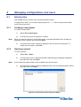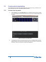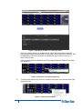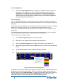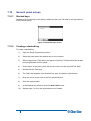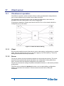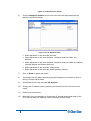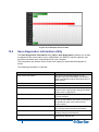
1
Eclipse HX Configuration Software (EHX) User Guide PN: Rev:399G064 A 08/29/13 Document Reference EHX User Guide Part Number: 399G064 Revision: A Legal Disclaimers Copyright © 2013 HME Clear-Com Ltd. All rights reserved. Clear-Com, the Clear-Com logo, and Clear-Com Concert are trademarks or registered trademarks of HM Electronics, Inc. The software described in this document is furnished under a license agreement and may be used only in accordance with the terms of the agreement. The product described in this document is distributed under licenses restricting its use, copying, distribution, and decompilation / reverse engineering. No part of this document may be reproduced in any form by any means without prior written authorization of Clear-Com, an HME Company. Clear-Com Offices are located in California, USA; Cambridge, UK; Montreal, Canada; and Beijing, China. Specific addresses and contact information can be found on Clear-Com’s corporate website: www.clearcom.com Clear-Com Contacts Americas and Asia-Pacific Headquarters California, United States Tel: +1.510.337.6600 Email: [email protected] Europe, Middle East, and Africa Headquarters Cambridge, United Kingdom Tel: +44 1223 815000 Email: [email protected] Canada Office Quebec , Canada Tel: +1 (450) 653-9669 China Office Beijing Representative Office Beijing, P.R.China Tel: +8610 65811360/65815577 2 Eclipse EHX Software User Guide Contents Document Reference ......................................................................................................... 2 Contents 3 1 Introduction to EHX ...................................................................................... 19 1.1 Further information .......................................................................................... 19 1.2 Terminology .................................................................................................... 19 1.3 System components ........................................................................................ 20 1.3.1 Central matrix ....................................................................................................... 20 1.3.2 Eclipse HX configuration software (EHX) ............................................................. 22 1.3.3 Setting up an Eclipse HX matrix system .............................................................. 22 1.3.4 EHX overview ....................................................................................................... 23 2 Getting started: installing, starting and exiting EHX ................................. 26 2.1 System requirements ...................................................................................... 26 2.2 Installing EHX.................................................................................................. 27 2.2.1 Backing up your existing projects and configurations .......................................... 27 2.2.2 Uninstalling and reinstalling EHX ......................................................................... 28 2.2.3 Installing EHX ....................................................................................................... 28 2.2.4 Importing your projects and configurations into EHX 7.5 ..................................... 28 2.2.5 Running EHX ........................................................................................................ 29 2.2.6 Identifying the EHX version .................................................................................. 31 3 EHX: setting up a system ............................................................................. 32 3.1 Introduction ..................................................................................................... 32 3.2 Matrix ethernet operation ................................................................................ 34 3.2.1 3.3 3 Configuration restrictions ...................................................................................... 34 Selecting ethernet or serial connection ........................................................... 34 3.3.1 Ethernet connection .............................................................................................. 35 3.3.2 Serial connection .................................................................................................. 39 3.3.3 Checking connections with the Windows ping utility ............................................ 40 3.4 Creating a project file ...................................................................................... 41 3.5 Setting up a new matrix ................................................................................... 41 3.5.1 Adding an offline matrix ........................................................................................ 41 3.5.2 Adding a discovered matrix .................................................................................. 43 3.5.3 Matrix preferences menu ...................................................................................... 44 3.5.4 Configuration options ............................................................................................ 53 Eclipse EHX Software User Guide 4 3.5.5 Firmware options .................................................................................................. 55 3.5.6 Delete matrix from project .................................................................................... 57 3.5.7 Apply changes to matrix ....................................................................................... 57 4 Managing configurations and users ........................................................... 60 4.1 Introduction ..................................................................................................... 60 4.1.1 Creating a new project.......................................................................................... 60 4.1.2 Opening a project ................................................................................................. 60 4.1.3 Closing a project ................................................................................................... 61 4.1.4 Importing and exporting a project ......................................................................... 61 4.1.5 Saving a project .................................................................................................... 62 4.1.6 Deleting a project .................................................................................................. 62 4.1.7 Importing/exporting configuration keysets ............................................................ 62 4.1.8 User management ................................................................................................ 64 4.1.9 Creating a new EHX user ..................................................................................... 66 4.1.10 Editing an existing EHX user ................................................................................ 67 4.1.11 Deleting a user...................................................................................................... 68 4.2 The EHX screen after a project has been loaded ........................................... 68 5 Configuring the Eclipse HX system ............................................................ 70 5.1 Using the left pane EHX menus ...................................................................... 70 5.2 Matrix hardware .............................................................................................. 71 5.3 Fonts ............................................................................................................... 71 5.3.1 Basic Latin ............................................................................................................ 72 5.3.2 Cyrillic ................................................................................................................... 72 5.3.3 Hangul .................................................................................................................. 72 5.3.4 Hiragana, Katakana and Kanji .............................................................................. 72 5.3.5 Arabic .................................................................................................................... 72 5.3.6 Half-width Katakana compatible panels ............................................................... 73 5.4 System configuration limits ............................................................................. 74 5.5 Online .............................................................................................................. 74 5.6 Matrix hardware setup ..................................................................................... 74 5.7 Adding an MVX-A16 card................................................................................ 75 5.8 Removing an MVX-A16 card ........................................................................... 76 5.9 Upgrading the MVX-A16 cards ....................................................................... 76 5.10 Port list options................................................................................................ 78 5.11 Show all ports.................................................................................................. 78 5.12 Detect new hardware ...................................................................................... 78 5.13 Show Alt Text .................................................................................................. 78 Eclipse EHX Software User Guide 5.14 Port number .................................................................................................... 79 5.15 Port function .................................................................................................... 79 5.15.1 5.16 5.16.1 Summary of expansion panels ........................................................................ 82 Deleting a port assignment ................................................................................... 83 5.17 Label ............................................................................................................... 83 5.18 Description ...................................................................................................... 83 5.19 Sorting ports .................................................................................................... 83 5.20 Column/row resizing........................................................................................ 83 5.21 Port properties................................................................................................. 84 5.21.1 Assignment panel (AP) panel options .................................................................. 84 5.21.2 Auxiliary relay options ........................................................................................... 84 5.21.3 Basic options ........................................................................................................ 84 5.21.4 Panel options ........................................................................................................ 85 5.21.5 IP port options....................................................................................................... 89 5.21.6 Assignment panel options .................................................................................... 90 5.21.7 Menu options ........................................................................................................ 90 5.21.8 Voice operated switch .......................................................................................... 91 5.21.9 Global options ....................................................................................................... 92 5.21.10 Gain options.......................................................................................................... 94 5.21.11 Audible alert options ............................................................................................. 95 5.21.12 Tally options.......................................................................................................... 96 5.21.13 Fast key assign options ........................................................................................ 96 5.21.14 Logic input options ................................................................................................ 98 5.21.15 Attached control options ....................................................................................... 99 5.21.16 DTMF options ....................................................................................................... 99 5.22 General Purpose Inputs (GPIs) ..................................................................... 100 5.22.1 Adding and removing GPI-6 modules ................................................................ 100 5.22.2 Configuring GPIs ................................................................................................ 101 5.23 General Purpose Outputs (GPOs) ................................................................ 101 5.23.1 Adding RLY-6 modules ....................................................................................... 102 5.23.2 Configuring GPOs .............................................................................................. 102 5.24 Configuring the E-FIB fiber card.................................................................... 102 5.24.1 Adding an E-FIB card ......................................................................................... 103 5.24.2 Removing an E-FIB card .................................................................................... 103 5.24.3 Configuring an E-FIB card .................................................................................. 103 5.25 5.25.1 5 Device details ....................................................................................................... 81 Configuring the E-Que card .......................................................................... 105 Adding an E-Que card ........................................................................................ 105 Eclipse EHX Software User Guide 5.26 5.26.1 Port function........................................................................................................ 106 5.26.2 Label ................................................................................................................... 106 5.26.3 Description .......................................................................................................... 106 5.26.4 Card properties ................................................................................................... 106 5.26.5 Codec ................................................................................................................. 107 5.27 T1 direct ........................................................................................................ 107 5.27.1 Port function........................................................................................................ 107 5.27.2 Label ................................................................................................................... 107 5.27.3 Description .......................................................................................................... 107 5.27.4 Card properties ................................................................................................... 108 5.27.5 Codec ................................................................................................................. 108 5.28 E1 trunk ......................................................................................................... 108 5.28.1 Port function........................................................................................................ 109 5.28.2 Label ................................................................................................................... 109 5.28.3 Description .......................................................................................................... 109 5.28.4 Card properties ................................................................................................... 109 5.28.5 Clock recovery .................................................................................................... 109 5.28.6 Codec ................................................................................................................. 109 5.29 T1 trunk ......................................................................................................... 110 5.29.1 Port function........................................................................................................ 110 5.29.2 Label ................................................................................................................... 110 5.29.3 Description .......................................................................................................... 110 5.29.4 Card properties ................................................................................................... 110 5.29.5 Clock recovery .................................................................................................... 110 5.29.6 Codec ................................................................................................................. 111 5.30 E1 direct/trunk ............................................................................................... 111 5.30.1 Port function........................................................................................................ 111 5.30.2 Label ................................................................................................................... 111 5.30.3 Description .......................................................................................................... 111 5.30.4 Card properties ................................................................................................... 111 5.30.5 Clock recovery .................................................................................................... 111 5.30.6 Codec ................................................................................................................. 112 5.31 6 E1 direct ........................................................................................................ 106 T1 direct/trunk ............................................................................................... 112 5.31.1 Port function........................................................................................................ 112 5.31.2 Label ................................................................................................................... 112 5.31.3 Description .......................................................................................................... 112 5.31.4 Card properties ................................................................................................... 112 5.31.5 Clock recovery .................................................................................................... 113 Eclipse EHX Software User Guide 5.31.6 5.32 E-QUE antenna ............................................................................................. 113 5.32.1 Port function........................................................................................................ 114 5.32.2 Label ................................................................................................................... 114 5.32.3 Description .......................................................................................................... 114 5.33 E-QUE splitter ............................................................................................... 114 5.33.1 Port function........................................................................................................ 114 5.33.2 Label ................................................................................................................... 115 5.33.3 Description .......................................................................................................... 115 5.34 Removing an E-Que card .............................................................................. 115 5.35 Configuring an E-Que card for antenna ........................................................ 115 5.35.1 Antenna connections .......................................................................................... 115 5.35.2 Cable length........................................................................................................ 116 5.35.3 Description .......................................................................................................... 116 5.35.4 Engineer comments ............................................................................................ 116 5.35.5 Listen label.......................................................................................................... 116 5.35.6 Talk label ............................................................................................................ 116 5.36 7 Codec ................................................................................................................. 113 Splitter connections ....................................................................................... 116 5.36.1 Cable length........................................................................................................ 117 5.36.2 Description .......................................................................................................... 117 5.36.3 Engineer comments ............................................................................................ 117 5.36.4 Label ................................................................................................................... 117 5.37 Antenna role map .......................................................................................... 117 5.38 E-Que trunk basic settings ............................................................................ 118 5.38.1 Port count ........................................................................................................... 118 5.38.2 Remote port count .............................................................................................. 118 5.38.3 Remote matrix .................................................................................................... 118 5.39 Configuring the IVC-32 card.......................................................................... 118 5.40 Adding an IVC-32 card .................................................................................. 118 5.40.1 Port number ........................................................................................................ 119 5.40.2 Port function........................................................................................................ 119 5.40.3 Label ................................................................................................................... 119 5.40.4 Description .......................................................................................................... 120 5.40.5 General ............................................................................................................... 120 5.40.6 IP port ................................................................................................................. 120 5.40.7 IP address assignment ....................................................................................... 120 5.40.8 IP address........................................................................................................... 121 5.40.9 Subnet mask ....................................................................................................... 121 5.40.10 Default gateway .................................................................................................. 121 Eclipse EHX Software User Guide 5.40.11 External IP address ............................................................................................ 121 5.40.12 External IP address IP port................................................................................. 121 5.40.13 Panel codecs ...................................................................................................... 121 5.41 5.41.1 5.42 5.42.1 5.43 Switch-back ........................................................................................................ 123 Configuring the LMC-64 card ........................................................................ 124 Adding an LMC-64 card...................................................................................... 124 Configuring the E-MADI64 card .................................................................... 126 5.43.1 Adding an e-MADI64 CARD (automatic discovery)............................................ 126 5.43.2 Adding an E-MADI64 card (manual addition) ..................................................... 127 5.43.3 Upgrading the E-MADI64 card firmware ............................................................ 128 5.44 Fixed groups ................................................................................................. 130 5.44.1 Fixed groups setup and configuration ................................................................ 131 5.44.2 Fixed group attached controls ............................................................................ 132 5.44.3 Fixed group basic options................................................................................... 132 5.44.4 Fixed group global settings................................................................................. 133 5.44.5 Fixed group call management ............................................................................ 133 5.44.6 Fixed group soft mode options ........................................................................... 134 5.45 Fixed group tallies ......................................................................................... 135 5.46 Sort groups.................................................................................................... 136 5.46.1 5.47 Basic options ...................................................................................................... 137 Key groups .................................................................................................... 137 5.47.1 Basic options ...................................................................................................... 138 5.47.2 Key group members ........................................................................................... 139 5.48 Partylines ...................................................................................................... 140 5.48.1 Partyline attached controls ................................................................................. 142 5.48.2 Partyline basic options ........................................................................................ 142 5.48.3 Partyline global options ...................................................................................... 143 5.48.4 Partyline fast key assign options ........................................................................ 143 5.48.5 Partyline tallies.................................................................................................... 144 5.48.6 Partyline global numbers .................................................................................... 144 5.49 8 Configuring an IVC-32 redundant card ......................................................... 121 Routes ........................................................................................................... 144 5.49.1 Description .......................................................................................................... 145 5.49.2 Source ................................................................................................................ 145 5.49.3 Action .................................................................................................................. 145 5.49.4 Destination .......................................................................................................... 146 5.49.5 Activate with talk ................................................................................................. 146 5.49.6 Activate with listen .............................................................................................. 146 5.49.7 Creating a route .................................................................................................. 146 Eclipse EHX Software User Guide 5.49.8 Assigning a source and destination to a route ................................................... 146 5.49.9 Delete a route ..................................................................................................... 147 5.50 5.50.1 Speed dial (DTMF sequences) ........................................................................... 148 5.50.2 Speed dial setup ................................................................................................. 148 5.50.3 Delete a speed dial ............................................................................................. 149 5.51 Controls ......................................................................................................... 149 5.51.1 Creating and deleting controls ............................................................................ 150 5.51.2 Properties ........................................................................................................... 151 5.51.3 Available ............................................................................................................. 152 5.51.4 Attached.............................................................................................................. 152 5.51.5 Relay naming ...................................................................................................... 152 5.51.6 TEL-14 configuration options.............................................................................. 152 5.51.7 Configuring DTMF access codes ....................................................................... 155 5.52 5.52.1 5.53 Logic Maestro ................................................................................................ 157 Preferences ........................................................................................................ 157 Beltpacks....................................................................................................... 157 5.53.1 Beltpack properties ............................................................................................. 158 5.53.2 Beltpack roles ..................................................................................................... 158 5.53.3 Matrix filtering ..................................................................................................... 164 6 IP devices..................................................................................................... 166 6.1 Introduction to IP devices .............................................................................. 166 6.2 IP panels ....................................................................................................... 168 6.3 Assigning a panel to an IVC-32 port ............................................................. 172 6.4 IP cards ......................................................................................................... 172 6.5 IVC-32 IP settings ......................................................................................... 173 6.5.1 9 Speed dials ................................................................................................... 148 IP port ................................................................................................................. 174 6.6 IVC-32 card panel list .................................................................................... 175 6.7 Concert users ................................................................................................ 177 6.7.1 Concert server dialog ......................................................................................... 178 6.7.2 Assigning a concert user to an IVC-32 port........................................................ 180 7 Panel programming .................................................................................... 181 7.1 The panel programming screen .................................................................... 181 7.2 V-series panel programming ......................................................................... 182 7.2.1 V-series lever key panels ................................................................................... 182 7.2.2 V-series pushbutton panels ................................................................................ 185 7.2.3 V-series rotary panels ......................................................................................... 188 7.2.4 V-series panel options ........................................................................................ 192 Eclipse EHX Software User Guide 7.3 7.3.1 Local assignment ................................................................................................ 196 7.3.2 Interlock group .................................................................................................... 196 7.3.3 Activation ............................................................................................................ 197 7.3.4 Local advanced latch disable ............................................................................. 197 7.3.5 Go to key destination .......................................................................................... 198 7.3.6 Delete key ........................................................................................................... 198 7.4 Concert panel options ................................................................................... 198 7.4.1 Page ................................................................................................................... 198 7.4.2 Save .................................................................................................................... 199 7.4.3 Load .................................................................................................................... 199 7.4.4 Copy ................................................................................................................... 200 7.4.5 Paste ................................................................................................................... 200 7.4.6 Clear ................................................................................................................... 200 7.4.7 Audio mixer ......................................................................................................... 200 7.4.8 Identify panel ...................................................................................................... 200 7.5 I-Series programming .................................................................................... 201 7.5.1 Assigning labels .................................................................................................. 201 7.5.2 Re-assignment of labels ..................................................................................... 202 7.5.3 I-Series label functions ....................................................................................... 202 7.5.4 I-series advanced functions ................................................................................ 205 7.5.5 Using EHX to set up I-Series fixed group membership options ......................... 205 7.5.6 Using EHX to Set up I-Series IFB options .......................................................... 205 7.5.7 Using EHX to set up I-Series partyline membership options ............................. 206 7.6 I-Series panel options ................................................................................... 206 7.6.1 Page ................................................................................................................... 207 7.6.2 Save .................................................................................................................... 207 7.6.3 Load .................................................................................................................... 207 7.6.4 Copy ................................................................................................................... 207 7.6.5 Paste ................................................................................................................... 207 7.6.6 Clear ................................................................................................................... 207 7.6.7 Audio mixer ......................................................................................................... 208 7.6.8 Identify panel ...................................................................................................... 208 7.7 Fast key assign restrictions (I-series) ............................................................ 208 7.8 Setting up assignment panel partyline membership options ......................... 208 7.9 Setting up assignment panel fixed group membership options ..................... 209 7.9.1 Keep hidden keys active (I-series panels) .......................................................... 209 7.10 General panel setups .................................................................................... 210 7.10.1 10 Concert panel programming .......................................................................... 194 Stacked keys ...................................................................................................... 210 Eclipse EHX Software User Guide 7.10.2 Creating a stacked key ....................................................................................... 210 7.10.3 Removing labels from a stacked key .................................................................. 211 7.10.4 Palette options .................................................................................................... 211 7.10.5 Key assignment .................................................................................................. 212 7.10.6 Default assignment mode ................................................................................... 212 7.10.7 Select unique search result ................................................................................ 213 7.10.8 Entity searching .................................................................................................. 213 7.10.9 Entity filtering ...................................................................................................... 213 7.10.10 Quick filtering ...................................................................................................... 213 7.11 11 Local advanced ............................................................................................. 214 7.11.1 Forced listen ....................................................................................................... 218 7.11.2 Blocked listen...................................................................................................... 218 7.11.3 Latch disable....................................................................................................... 219 7.11.4 Local ISO ............................................................................................................ 219 7.11.5 Local IFB............................................................................................................. 219 7.11.6 Route monitor ..................................................................................................... 219 7.11.7 Mute relay ........................................................................................................... 219 7.11.8 Preset talk ........................................................................................................... 220 7.11.9 Preset listen ........................................................................................................ 220 7.11.10 Preset call ........................................................................................................... 220 7.11.11 Call signal to a TEL-14 ....................................................................................... 220 7.11.12 Nearby panels..................................................................................................... 220 8 Audio Mixer.................................................................................................. 221 8.1 Introduction to Audio Mixer ........................................................................... 221 8.2 Audio Mixer panel ......................................................................................... 221 8.2.1 Save to EHX configuration and exit .................................................................... 222 8.2.2 Restore to default values .................................................................................... 223 8.2.3 Save to file .......................................................................................................... 223 8.2.4 Load from file ...................................................................................................... 223 8.2.5 Layout settings.................................................................................................... 223 8.2.6 Input area............................................................................................................ 224 8.2.7 Crosspoints ......................................................................................................... 229 8.2.8 Output area ......................................................................................................... 232 9 Online mode ................................................................................................ 233 9.1 Introduction to Online mode .......................................................................... 233 9.2 Entering online mode .................................................................................... 234 9.3 Using online mode ........................................................................................ 236 9.4 Online limitations ........................................................................................... 237 Eclipse EHX Software User Guide 9.5 Exiting online mode ....................................................................................... 237 10 Networking................................................................................................... 239 10.1 Network system configuration ....................................................................... 239 10.1.1 Configuration passwords .................................................................................... 239 10.1.2 Using the layout pane ......................................................................................... 240 10.1.3 Allocating a configuration to a matrix ................................................................. 241 10.1.4 Deleting a matrix from the project....................................................................... 241 10.1.5 Uploading the last downloaded configuration from the matrix ........................... 242 10.2 12 Intelligent linking (trunking) ........................................................................... 242 10.2.1 Fiber trunking ...................................................................................................... 243 10.2.2 Four-wire trunks .................................................................................................. 244 10.2.3 IP directs and trunks ........................................................................................... 244 10.3 Programming remote labels .......................................................................... 248 10.4 Remote fixed groups ..................................................................................... 248 10.5 Remote partylines ......................................................................................... 249 10.6 Remote 2-way radio ...................................................................................... 250 10.7 Remote telephone ......................................................................................... 250 10.7.1 Remote manual dial ............................................................................................ 250 10.7.2 Remote speed dial .............................................................................................. 250 10.7.3 Off hook and off hook tally .................................................................................. 251 10.7.4 Auto listen ........................................................................................................... 251 10.8 Remote controls ............................................................................................ 251 10.9 Remote secondary actions ............................................................................ 253 11 Client server ................................................................................................ 254 11.1 Client/server operation .................................................................................. 254 11.1.1 Client................................................................................................................... 254 11.1.2 Server ................................................................................................................. 254 11.1.3 Initial setup.......................................................................................................... 255 12 Eclipse HX downloads ................................................................................ 262 12.1 Apply changes to matrix ................................................................................ 262 12.1.1 Apply changes with reset (red reset) .................................................................. 263 12.1.2 Apply changes with reset and clear all memory (black reset) ............................ 263 12.2 Apply to all matrices ...................................................................................... 264 12.3 Preserving locally assigned keys .................................................................. 264 12.4 Apply changes to all matrices ....................................................................... 264 13 Using the diagnostic tools ......................................................................... 266 13.1 Crosspoint map ............................................................................................. 266 Eclipse EHX Software User Guide 13.1.1 13.2 Crosspoint settings and averaging ..................................................................... 269 Matrix event log ............................................................................................. 270 13.2.1 Request info........................................................................................................ 271 13.2.2 Audio alerts ......................................................................................................... 272 13.2.3 Changing matrix IP address ............................................................................... 273 13.2.4 System monitoring .............................................................................................. 275 13.3 Resource chart .............................................................................................. 277 13.4 Save diagnostics information utility ............................................................... 278 13.5 Clear unused memory ................................................................................... 279 14 Glossary ....................................................................................................... 280 15 Limited Warranty ......................................................................................... 284 16 Technical Support & Repair Policy ........................................................... 287 APRIL 29, 2010 ............................................................................................................... 287 TECHNICAL SUPPORT POLICY ................................................................................................... 287 RETURN MATERIAL AUTHORIZATION POLICY ......................................................................... 288 REPAIR POLICY 289 13 Eclipse EHX Software User Guide SOFTWARE LICENSE AGREEMENT IMPORTANT–THIS IS A LEGAL AGREEMENT BETWEEN YOU AND CLEAR-COM. BEFORE DOWNLOADING, ACCESSING, OR USING ANY PART OF THE SOFTWARE, YOU SHOULD READ CAREFULLY THE FOLLOWING TERMS AND CONDITIONS CONTAINED IN THIS SOFTWARE LICENSE AGREEMENT ("AGREEMENT") AS THEY GOVERN YOUR ACCESS TO AND USE OF THE SOFTWARE. CLEAR-COM IS WILLING TO LICENSE AND ALLOW THE USE OF THIS SOFTWARE ONLY ON THE CONDITION THAT YOU ACCEPT AND AGREE TO ALL OF THE TERMS AND CONDITIONS CONTAINED IN THIS AGREEMENT. IF YOU DO NOT AGREE WITH THIS AGREEMENT, YOU ARE NOT GRANTED PERMISSION TO ACCESS OR OTHERWISE USE THE SOFTWARE. This Agreement applies to any computer program and related files (the “Software”) offered to you by either Clear-Com LLC or HME Clear-Com Ltd. (each of whom is referred to herein as “Clear-Com”) and whether the software is delivered in the form of a diskette, DVD, USB storage device or CD-ROM (the “Storage Media”), over the Internet or through an on-line network. Your use of the Software constitutes your acceptance of the following terms and conditions. TERMS AND CONDITIONS 14 1) License Grant. The Software is provided by Clear-Com, and this Agreement provides to you a personal, revocable, limited, non-exclusive, royalty-free, nontransferable license to use the Software conditioned on your continued compliance with the terms and conditions of this Agreement. This Agreement permits you to use and access for personal or business purposes the Software only at a single physical location in connection with the use of Clear-Com products. You may also load information from the Software into your laptop, workstation, or computer temporary memory (RAM) and print and download materials and information from the Software solely for your personal or business use, provided that all hard copies contain all copyright and other applicable notices contained in such materials and information. If you are using the Software on behalf of a company or other form of entity, please note that such a company or entity may have a separate agreement with Clear-Com regarding access and usage privileges for the Software. Nevertheless, your use of the Software will be subject to the obligations and restrictions regarding use of the Software as set forth in this Agreement. 2) Restrictions. The license granted under this Agreement is limited. You may not use, copy, store, reproduce, transmit, distribute, display, rent, lease, sell, modify, alter, license, sublicense, or commercially exploit any data provided by Clear-Com through the Software in any manner not expressly permitted by this Agreement. In addition, you may not modify, translate, decompile, create any derivative work(s) of, copy, distribute, disassemble, broadcast, transmit, publish, remove or alter any proprietary notices or labels, license, sublicense, transfer, sell, mirror, frame, exploit, rent, lease, private label, grant a security interest in, or otherwise use the Software in any manner not expressly permitted herein. Eclipse EHX Software User Guide 15 3) User Obligations. By downloading, accessing, or using the Software in order to view our information and materials or submit information of any kind, you represent that you are at least 18 years of age and will, at all times, provide true, accurate, current, and complete information when submitting information or materials on the software including, without limitation, when you provide information via a software registration or submission form. In addition, you agree to abide by all applicable local, state, national, and international laws and regulations with respect to your use of the software. This Agreement is also expressly made subject to any applicable export laws, orders, restrictions, or regulations. 4) Proprietary Rights. This Agreement provides only a limited license to access and use the Software. Accordingly, you expressly acknowledge and agree that ClearCom transfers no ownership or intellectual property interest or title in and to the Software to you or anyone else. All text, graphics, user interfaces, visual interfaces, photographs, sounds, artwork, computer code (including html code), programs, software, products, information, and documentation as well as the design, structure, selection, coordination, expression, "look and feel," and arrangement of any content contained on or available through the Software, unless otherwise indicated, are owned, controlled, and licensed by Clear-Com and its successors and assigns and are protected by law including, but not limited to, United States copyright, trade secret, patent, and trademark law, as well as other state, national, and international laws and regulations. Except as expressly provided herein, Clear-Com does not grant any express or implied right to you or any other person under any intellectual or proprietary rights. Accordingly, your unauthorized use of the Software may violate intellectual property or other proprietary rights laws as well as other laws, regulations, and statutes. The name of the Software, the Clear-Com logo, and all other names, logos, and icons identifying Clear-Com and its programs, products, and services are proprietary trademarks of Clear-Com, and any use of such marks, including, without limitation, as domain names, without the express written permission of Clear-Com is strictly prohibited. Other service and entity names mentioned herein may be the trademarks and/or service marks of their respective owners. 5) Feedback and Submissions. Clear-Com welcomes your feedback and suggestions about Clear-Com’s products or services or the Software. By transmitting any suggestions, information, material, or other content (collectively, "feedback") to Clear-Com, you represent and warrant that such feedback does not infringe or violate the intellectual property or proprietary rights of any third party (including, without limitation, patents, copyrights, or trademark rights) and that you have all rights necessary to convey to Clear-Com and enable Clear-Com to use such feedback. In addition, any feedback received will be deemed to include a royalty-free, perpetual, irrevocable, transferable, non-exclusive right and license for Clear-Com to adopt, publish, reproduce, disseminate, transmit, distribute, copy, use, create derivative works, and display (in whole or in part) worldwide, or act on such feedback without additional approval or consideration, in any form, media, or technology now known or later developed for the full term of any rights that may exist in such content, and you hereby waive any claim to the contrary. Eclipse EHX Software User Guide 6) Limited Warranty. 6.1 Clear-Com warrants that any Storage Media on which the Software is stored will be free from defects in materials and workmanship for 90 days from the date you acquire it. If a defect in the Storage Media occurs, return the Storage Media to Clear-Com and Clear-Com will replace it at no cost to you. This remedy is your exclusive remedy for breach of this warranty. This limited warranty is void if the damage or defect has resulted from accident, abuse or misapplication. 6.2 WHILE CLEAR-COM ENDEAVORS TO PROVIDE RELIABLE INFORMATION, SERVICES, PROGRAMS, SOFTWARE, AND MATERIALS, EXCEPT AS SPECIFICALLY PROVIDED IN SECTION 6.1, THE SOFTWARE IS PROVIDED ON AN "AS-IS" AND "AS AVAILABLE" BASIS AND MAY INCLUDE ERRORS, OMISSIONS, OR OTHER INACCURACIES. YOU ASSUME THE SOLE RISK OF MAKING USE OF THE SOFTWARE. CLEAR-COM MAKES NO REPRESENTATIONS OR WARRANTIES ABOUT THE RESULTS THAT CAN BE ACHIEVED FROM OR THE SUITABILITY, COMPLETENESS, TIMELINESS, RELIABILITY, LEGALITY, OR ACCURACY OF THE SOFTWARE FOR ANY PURPOSE, AND EXPRESSLY DISCLAIMS ALL WARRANTIES, EXPRESS OR IMPLIED, INCLUDING, WITHOUT LIMITATION, ANY WARRANTY OF MERCHANTABILITY, FITNESS FOR A PARTICULAR PURPOSE, OR NONINFRINGEMENT OR ANY OTHER IMPLIED WARRANTY UNDER THE UNIFORM COMPUTER INFORMATION TRANSACTIONS ACT AS ENACTED BY ANY STATE. CLEAR-COM ALSO MAKES NO REPRESENTATION OR WARRANTY THAT THE SOFTWARE WILL OPERATE ERROR FREE OR IN AN UNINTERRUPTED FASHION OR THAT ANY DOWNLOADABLE FILES OR INFORMATION WILL BE FREE OF VIRUSES OR CONTAMINATION OR DESTRUCTIVE FEATURES. 7) 16 Limitation of Liability. You expressly absolve and release Clear-Com from any claim of harm resulting from a cause beyond Clear-Com’s control, including, but not limited to, failure of electronic or mechanical equipment or communication lines, telephone or other connection problems, computer viruses, unauthorized access, theft, operator errors, severe weather, earthquakes, or natural disasters, strikes, or other labor problems, wars, or governmental restrictions. MOREOVER, IN NO EVENT SHALL CLEAR-COM BE LIABLE FOR ANY INDIRECT, PUNITIVE, INCIDENTAL, SPECIAL, EXEMPLARY, MULTIPLE, INDIRECT OR CONSEQUENTIAL DAMAGES ARISING OUT OF OR IN ANY WAY CONNECTED WITH THE USE OF THE SOFTWARE, WITH ANY DELAY OR INABILITY TO USE THE SOFTWARE, OR FOR ANY INFORMATION, SERVICES, PROGRAMS, PRODUCTS, AND MATERIALS AVAILABLE THROUGH THE SOFTWARE, WHETHER BASED IN CONTRACT, TORT, STRICT LIABILITY, OR OTHERWISE, EVEN IF CLEAR-COM HAS BEEN ADVISED OF THE POSSIBILITY OF SUCH DAMAGES. BECAUSE SOME JURISDICTIONS DO NOT ALLOW THE EXCLUSION OR LIMITATION OF LIABILITY FOR CONSEQUENTIAL OR INCIDENTAL DAMAGES, THE ABOVE LIMITATION MAY NOT APPLY. NOTWITHSTANDING THE FOREGOING, TOTAL LIABILITY OF CLEAR-COM FOR ANY REASON WHATSOEVER RELATED TO USE OF THE SOFTWARE SHALL NOT EXCEED THE TOTAL AMOUNT PAID BY YOU TO CLEAR-COM TO PURCHASE THE SOFTWARE. Eclipse EHX Software User Guide 8) Indemnity. You agree to protect, defend, indemnify, and hold harmless ClearCom and its affiliates and all of their respective employees, agents, directors, officers, shareholders, attorneys, successors, and assigns from and against any and all claims, proceedings, damages, injuries, liabilities, losses, costs, and expenses (including reasonable attorneys’ fees and litigation expenses) relating to or arising from any breach by you of this Agreement. 9) Legal Matters. 9.1 If you are resident or domiciled anywhere other than Europe, the Middle East or Africa, this Agreement will be construed and enforced solely in accordance with the laws of the State of California, U.S.A., and courts in California shall have exclusive subject matter jurisdiction, personal jurisdiction, and venue to adjudicate any dispute arising out of this Agreement. 9.2 If you are resident or domiciled in Europe, the Middle East or Africa (the “EMEA”), this Agreement will be construed and enforced solely in accordance with English law and English Courts shall have exclusive subject matter jurisdiction, personal jurisdiction and venue to adjudicate any dispute arising out of this Agreement. 9.3 You agree to waive any right to a jury trial in connection with any action or litigation in any way arising out of or related to this Agreement and acknowledge that either party may seek attorney's fees in any proceeding. Any claim you might have against Clear-Com must be brought within two (2) years after the cause of action arises, or such claim or cause of action will be barred. You also acknowledge and agree that any applicable state law implementation of the Uniform Computer Information Transactions Act (including any available remedies or laws) shall not apply to this Agreement and is hereby disclaimed. 9.4 Clear-Com makes no representation that the Software is appropriate or available for use in locations outside the State of California or the EMEA and access to or use of the Software from states, territories, or nations where any aspect of the Software is illegal is prohibited. You access or use the Software on your own volition and are responsible for compliance with all applicable local laws with respect to your access and use of the Software. 9.5 A printed version of this Agreement and of any related notice given in electronic form shall be admissible in judicial or administrative proceedings based upon or relating to this Agreement to the same extent and subject to the same conditions as other business documents and records originally generated and maintained in printed form. 9.6 Clear-Com has no obligation to provide free updates to or upgrades of the Software or to provide support of any kind with respect to the Software. 9.7 If you are acquiring the Software for an agency of the United States Government, the provisions of Federal Acquisition Regulations Section 12.212 or Department of Defense FAR Supplement Section 227.7202-3, as applicable, apply to such acquisition. 10) 17 Term and Termination. This Agreement and your right to use the Software will take effect at the moment you click "I ACCEPT" or you install, access, or use the Software and is effective until terminated as set forth below. This Agreement will terminate automatically if you click "I REJECT." In addition, Clear-Com reserves the right at any time and on reasonable grounds, which shall include, without limitation, any reasonable belief of fraudulent or unlawful activity or actions or omissions that violate any term or condition of this Agreement, to deny your Eclipse EHX Software User Guide access to the Software or to any portion thereof in order to protect its name and goodwill, its business, or other authorized users, and this Agreement will also terminate automatically if you fail to comply with this Agreement, subject to the survival rights of certain provisions identified below. Termination will be effective without notice. You may also terminate this Agreement at any time by ceasing to use the Software, but all applicable provisions of this Agreement will survive termination, as identified below. Upon termination, you must destroy all copies of any aspect of the Software in your possession. In addition to the miscellaneous section below, the provisions concerning Clear-Com’s proprietary rights, feedback, indemnity, disclaimers of warranty, limitation of liability, and governing law will survive the termination of this Agreement for any reason. 11) 18 Miscellaneous. You acknowledge that any breach, threatened or actual, of this Agreement will cause irreparable injury to Clear-Com, such injury would not be quantifiable in monetary damages, and Clear-Com would not have an adequate remedy at law. You therefore agree that Clear-Com shall be entitled, in addition to other available remedies, to seek and be awarded an injunction or other appropriate equitable relief from a court of competent jurisdiction restraining any breach, threatened or actual, of your obligations under any provision of this Agreement. Accordingly, you hereby waive any requirement that Clear-Com post any bond or other security in the event any injunctive or equitable relief is sought by or awarded to Clear-Com to enforce any provision of this Agreement. The parties agree that this Agreement is for the benefit of the parties hereto as well as Clear-Com's licensors. Accordingly, this Agreement is personal to you, and you may not assign your rights or obligations to any other person or entity without Clear-Com's prior written consent. Failure by Clear-Com to insist on strict performance of any of the terms and conditions of this Agreement will not operate as a waiver by Clear-Com of that or any subsequent default or failure of performance. If any provision (or part thereof) contained in this Agreement is determined to be void, invalid, or otherwise unenforceable by a court of competent jurisdiction or on account of a conflict with an applicable government regulation, such determination shall not affect the remaining provisions (or parts thereof) contained herein and the illegal, invalid, or unenforceable clause shall be modified in compliance with applicable law in a manner that most closely matches the intent of the original language. No joint venture, partnership, employment, or agency relationship exists between you and Clear-Com as a result of this Agreement or your utilization of the Software. Headings herein are for convenience only. This Agreement represents the entire agreement between you and Clear-Com with respect to use of the Software, and it supersedes all prior or contemporaneous communications and proposals, whether electronic, oral, or written between you and Clear-Com with respect to the Software. Eclipse EHX Software User Guide 1 Introduction to EHX This guide describes the features of EHX, the configuration software for Eclipse HX. EHX is used to create and manage communication pathways between your Eclipse HX devices, including matrices, interface cards, interface modules and user panels. For example, use EHX to: • Create individual, point-to-point talk and listen paths between members of a matrix intercom system. • Create groups and one-to-many calls (fixed groups). • Create many-to-many partylines. • Store complete system setups (configurations) on the EHX PC. • Download and instantly implement a configuration on the matrix. • Store four complete configuration maps in the matrix on-board memory, any of which can be activated immediately from the front of the matrix with the push of a button. • Communicate with CellCom® and FreeSpeak® beltpacks allowing direct communication between panels and roaming users. • Communicate with remote panels over IP. • Interface with the Clear-Com Concert ™ multi-user conferencing system over IP. • Interface with HelixNet Partyline™, the Clear-Com digital partyline system. • Interface with telephones, two-way radios, camera intercoms, and more. • Bring an outside audio source, such as program source, into the system’s audio stream and interrupt the program audio for announcements (IFBs). • Use the GPIO facility to activate an applause light in a studio, a lock on a door, or other control functions each time an external device such as a switch is triggered. • Control, monitor, or run diagnostics on a matrix system remotely from anywhere in the world, if the matrix is set up on a LAN network. • Link matrices across cities, nations, and continents. 1.1 Further information For more information about the Eclipse HX matrix system, including matrices, interface cards, interface modules and user panels, see the complete Eclipse HX documentation set. Eclipse HX documentation is available from both the Clear-Com website (www.clearcom.com) and the Eclipse HX v7.5 software and documentation DVDs. 1.2 Terminology Remote devices (including interface cards, interface modules, interface frames and user panels) connected to the matrix may be referred to as panels in this guide. Occasional references may be made to stations (a legacy Clear-Com term). 19 Eclipse EHX Software User Guide 1.3 System components A complete Eclipse HX system comprises the Eclipse HX configuration software (EHX), a central hardware matrix, user panels and other remote devices - interfaces, four-wire equipment—connected to the matrix. The following sections give a brief overview of the matrix system. 1.3.1 Central matrix The matrix hardware assembly comprises the following components: • The metal housing (sometimes called the frame). • The central processing unit (CPU). • The internal circuitry which controls the attached devices. • Power supplies. • The rear panel interfaces which link the matrix to user panels and remote devices such as interface modules. • The rear panel interfaces which link the matrix to CellCom/FreeSpeak antennae. • The rear panel interfaces, which provide fiber-optic links between matrices. Figure 1-1 Eclipse HX-Omega Matrix Chassis The matrix chassis (frame) is a metal rectangular box which houses the matrix internal circuitry and power supplies, as follows: • The Eclipse HX-Median and Eclipse HX-Delta are designed to host removable CPU cards, interface cards, and interface modules. • The Eclipse HX-Omega is designed to host removable CPU and interface cards. • The Eclipse HX-PiCo contains fixed internal circuitry. The larger matrices (Eclipse HX-Omega, Eclipse HX-Median and Eclipse HX-Delta) have removable power supplies, which can be exchanged when necessary. 20 Eclipse EHX Software User Guide Central processing unit (CPU) The central processing unit (CPU) provides the serial data and Ethernet connection to the PC hosting the EHX software. The CPU also coordinates the data flow for other features of the system, such as generalpurpose outputs and inputs. The CPU stores four complete system configurations in its memory, which can be retrieved and activated directly from the matrix front-panel controls, even when the matrix is not connected to a computer. • Each matrix system contains at least one central processing unit, located either on its own removable CPU card, or in internal circuitry. The Eclipse HX-Omega, Eclipse HX-Median and Eclipse HX-Delta are supplied with two CPU cards (in a master and slave relationship), ensuring fail-safe operation. Internal circuitry The matrix internal circuitry controls the operation of the panels and interfaces connected to it. Panels and interfaces connect to the internal circuitry through an RJ-45 connector, or port, on the rear panel of the matrix. The internal circuitry sends balanced duplex audio and RS-422 data signals to and from connected audio equipment through 4-pair shielded category-5 (CAT5) cable (STP). Each audio device connected to the matrix can communicate with all other audio devices in the system. For intelligent linking, shielded category-5 cable is run from a port on one Eclipse matrix to a port on a second Eclipse matrix to form a trunkline connection. The Eclipse HX-Omega, Eclipse HX-Median and Eclipse HX-Delta matrix internal circuitry can also control fiber optic interfaces to provide high-speed links between matrices and E1 interfaces to allow communication with wireless system antennae. Power supplies Each Eclipse HX-Median, Eclipse HX-Omega or Eclipse HX-Delta matrix can hold two independent power supplies. These may be connected to a main and backup power source for redundancy. If one of these power supplies fails, the second supply automatically takes over. In the event of a complete power failure, a matrix can automatically restore itself to complete functioning by retrieving configuration information from its non-volatile operational memory. The Eclipse HX-PiCo matrix has a dual AC input power supply unit. Rear-panel connectors A matrix connects to remote devices such as user panels, interfaces, general purpose inputs and outputs, local area networks (LANs), the computer that hosts the EHX configuration software, and other matrices through its rear-panel connectors. The rear-panel RJ-45 sockets, or ports, connect the matrix to intercom panels, beltpack antennas, Concert servers, other matrices and interfaces with shielded category 5 (CAT5) cable. 21 Eclipse EHX Software User Guide 1.3.2 Eclipse HX configuration software (EHX) The Eclipse HX configuration software (EHX) controls the operation of the system’s connected audio devices, using a configuration (sometimes called a configuration map) that has been downloaded to the matrix. The system is designed in a star configuration, in which each member of the system connects directly to the matrix rather than to each other. Audio signals are routed through the central matrix and out to the connected audio devices in accordance with the configuration created in EHX. EHX can also be used to monitor the matrix for faults and to log errors for analysis. The EHX software comprises a graphical user interface with a main screen that is divided into two parts: • The Menu pane – This is located on the left of the EHX main screen. It contains the System, Hardware, Configuration and Diagnostics drop-down menu lists. • The System pane – This is located on the right of the EHX main screen. It contains a graphical representation of the matrices that are present in the system. 1.3.3 Setting up an Eclipse HX matrix system The following procedure shows the basic steps for setting up an Eclipse HX matrix system. For detailed installation information, see the Eclipse HX Installation Guide. To set up an Eclipse HX matrix system (basic steps): 1) Ensure that there is a working connection between the EHX PC and the matrix (see 3 EHX: setting up a system for information on selecting the connection type and setting ethernet addresses). 2) Open EHX. Go to System and right click the Systems Pane to open the Add Matrix option. Note: 22 The Systems Pane is located at the right-hand of the screen. 3) To add a new matrix, click Add Matrix. Open the matrix type menu by clicking Please choose a matrix type and select the required matrix type. 4) Click New Matrix on the new, onscreen matrix icon and enter the name of the new matrix. 5) Enter the IP address of the new matrix in the Matrix IP Address window of the new matrix icon. 6) Go to Hardware > Cards and Ports. 7) Eclipse HX-Omega, Eclipse HX-Median and Eclipse HX-Delta only: Select each of the MVX-A16 cards to correspond to the cards fitted to the matrix. This displays the list of ports for that card. Add the required panels and interfaces to the ports. 8) Eclipse HX-Omega, Eclipse HX-Median and Eclipse HX-Delta only: Select each E-QUE card fitted and configure the ports (according to the type of card configured in Card Properties). Eclipse EHX Software User Guide Note: 1.3.4 9) Eclipse HX-Omega, Eclipse HX-Median and Eclipse HX-Delta only: Select each IVC-32 card fitted and configure the card for IP communication, using Card Properties. 10) Eclipse HX-Omega, Eclipse HX-Median and Eclipse HX-Delta only: Select each LMC-64 card fitted and configure the card for IP communication, using Card Properties. 11) Eclipse HX-Omega, Eclipse HX-Median and Eclipse HX-Delta only: Select each E-MADI64 card fitted, and configure the card for MADI communication using Card Properties. 12) Go to Configuration > Panels. Configure the keys on any connected V-Series and I-Series user panels, using the list of sources and destinations. 13) When you have finished your configuration, download the configuration map to the matrix by clicking Tools > Apply Changes To Matrices or Tools > Apply Changes To Matrix if there is only one matrix. You can also apply changes by right-clicking a matrix in the Layout screen, and selecting Apply Changes to Matrix. EHX overview The following sections describe some of the main elements of the Eclipse HX Configuration Software. Setting up matrix port functions Each physical port on the matrix needs to know what type of remote device connects to it. This could be one of the many different types of Clear-Com intercom panels, control panels, or interfaces that connect the matrix to telephones, 2-way radios, and so on. Each port also needs a label to identify it on intercom panels and other connected equipment. Labels can be up to ten characters in length, or can be split into two parts, each part limited to five characters. Assigning names to individual panels At individual panels and interfaces, port labels are assigned to specific keys or buttons. If an operator communicates frequently with a source or destination in the matrix system a key or button may be assigned on a panel for either talking or listening directly to that source or destination. These individual buttons or keys are similar to speed dials on a traditional telephone. Each key can be set up so that when it is pressed, it makes an audio route. For example a key on a panel attached to port 1 may be programmed to send audio to port 28. When that key is pressed, an audio route is activated from the originating panel to the device connected to port 28. When the key is released, the route is de-activated (these audio routes are also called crosspoints). 23 Eclipse EHX Software User Guide Figure 1-2 Key Assignment Projects and configurations A configuration determines the operating parameters of the Eclipse HX system, including port functions, talk-and-listen audio routes, controls and other functions. Configurations are created and managed in EHX, for download to the matrices. Up to four configurations can be stored in the operational memory of the matrix. Pushing a button on the front panel of the matrix applies the configuration to the matrix, and any devices connected to the matrix. You can create: • A configuration for just one matrix and/or multiple, intelligently linked matrices. • Multiple, alternate configurations for that matrix, and/or system of linked matrices, to address different intercom requirements. For example, you might want to create separate configurations for a live sports broadcast and the main evening news broadcast. A project is a container that manages and organises your Eclipse HX matrices and their configurations. The project can be used to define every aspect of a complex intercom system, including the connectivity between multiple, intelligently linked matrices and/or the configurations for individual matrices. An unlimited number of projects may be stored on the EHX PC or on a server. Note: The following sections describe some of the types of communications routes that can be created with EHX. Subsequent chapters in this manual describe these topics in detail. Groups: partyline and fixed Group communication may be configured in several ways. In a fixed group configuration, an operator speaks to all members of the group at once. However, if a group member responds by calling the operator back with their answer-back key the audio path goes to operator panel only. Alternatively, all members of a group can speak with all other members of the group at the same time. This is commonly called a conference or partyline. It is similar to a telephone conference call with its two-way, full-duplex communication. Members of a partyline can join and leave in real time, making the membership dynamic in the sense that it is always changing. 24 Eclipse EHX Software User Guide Controls: DTMF sequences, relays, routes An intercom panel can be used to perform a variety of other functions besides sending audio. These are called control functions. For example, it can activate: • A Dual Tone Multi Frequency (DTMF) sequence to call out on a telephone line. • An electronic relay to turn on a light or lock a door. • Audio from an external router like a mixer desk. Call signals A call signal is an audible or visual signal or Tally sent on an intercom channel, with or without accompanying audio. These signals have a variety of purposes from alerting an operator who has taken off their headset, to activating control sequences. Interruptible Foldback (IFB) An audio source such as on-the-air or program audio can be routed through the matrix to a presenters ear pieces. In a typical broadcast application, program audio is routed to the talent– a collective term for any person in front of the camera broadcasting directly to an audience. A director or other audio person can then interrupt or dim the program audio to the talent for announcements (commands) or cuing by using the interruptible foldback or IFB feature. 25 Eclipse EHX Software User Guide 2 Getting started: installing, starting and exiting EHX 2.1 System requirements EHX runs on the following versions of Windows: • Microsoft Windows Server 2003 SP2 (32-bit and 64-bit). • Microsoft Windows Server 2003 R2 (32-bit and 64-bit). • Microsoft Windows Server 2008 SP2 (32-bit and 64-bit). • Microsoft Windows Server 2008 R2 (64-bit). Note: Windows Server 2008 R2 is only available in a 64 bit version (no 32 bit version is available). • Microsoft Windows XP SP3 (32-bit and 64-bit). • Microsoft Windows Vista SP2 (32-bit and 64-bit). • Microsoft Windows 7 (32-bit and 64-bit). • Microsoft Windows 8 (32-bit and 64-bit) Note: When running EHX on Windows OS, you can run the client and server on separate machines, connected over the network. The minimum requirements for the PC hosting EHX are as follows: Specification Value / Description Processor 1 GHz Memory 1 GB RAM Hard Disk 1 GB Input Devices CD/DVD-ROM drive Display Resolution SVGA User Entry Keyboard, Mouse Network IEEE 802.3 Ethernet card Table 2-1 Minimum PC Requirements The recommended requirements for the PC hosting EHX are: Specification Value / Description Processor 2 GHz for a client. As many cores as possible for a server Memory 2 GB for a 32-bit client 3 GB for a 32-bit server 4 GB for a 64-bit client 4 GB for a 64-bit server Free Space 1 GB Display Resolution 1600 x 1200 Ports One serial port Table 2-2 Recommended PC Requirements 26 Eclipse EHX Software User Guide 2.2 Installing EHX 2.2.1 Backing up your existing projects and configurations If you are upgrading from an earlier version of EHX/ECS, Clear-Com recommends backing up your projects and configurations before you install EHX. Backing up ECS 5.2.4 projects and configuration To back up and export your exiting ECS 5.2.4 projects and configurations: 1) Open the project you want to export. 2) Select File > Export Project. 3) Save the project to a location on your hard drive. The project is saved as a *.ccn format file, which you can import later into EHXv7.5 Note: 4) EHX can open *.ccn format files as well as its own *.hxn format files. Repeat the above procedure for all the projects you want to save. Backing up EHX 7.0/7.1 projects and configurations To back up and export your exiting EHX 7.0/7.1 projects and configurations in Client Server mode: 1) Open the project you want to export. 2) Select File > Export Project. 3) Save the project to a location on your hard drive. The project is saved as a *.ccn format file, which you can import later into EHXv7.5 Note: 4) EHX can open *.ccn format files as well as its own *.hxn format files. Repeat the above procedure for all the projects you want to save. To back up and export your exiting EHX 7.0/7.1 projects and configurations in Client Only mode: 5) Open the project you want to export. 6) Select File > Save Project. 7) Save the project to a location on your hard drive. The project is saved as a *.ccn format file, which you can import later into EHXv7.5 Note: 8) 27 EHX can open *.ccn format files as well as its own *.hxn format files. Repeat the above procedure for all the projects you want to save. Eclipse EHX Software User Guide 2.2.2 Uninstalling and reinstalling EHX Configurations If you are required to uninstall and re-install your EHX installation for any reason, ensure that you save your projects first for re-importing into EHX (see 2.2.1 Backing up your existing projects and configurations and 2.2.4 Importing your projects and configurations into EHX). You can uninstall EHX from your Windows All Programs menu. If you are running EHX in Client-Server mode, export your projects to a secure location on your hard drive in the same way as in 2.2.1 Backing up your existing projects and configurations. Note: 2.2.3 If you are running EHX in Client-Only mode, where the user works directly with *.hxn project files, your projects should already be saved prior to uninstall. Installing EHX The Eclipse HX v7.5 software DVD contains a number of executables for installing EHX: Installation *.exe Description EHXSetup.exe Installer for the 32-bit and 64-bit versions of the client. Use the EHX client version to connect directly to the matrix in Client-only mode or to an EHX server in Client-Server mode. EHXServerSetup.exe Installer for the 32-bit server and 64-bit server versions of EHX. The EHX server enables multiple EHX clients to work together when configuring an Eclipse HX v7.5 system. Table 2-3 EHX Installation Executables Note: 2.2.4 Before Installing EHX Server, please see Installing and Configuring IIS on the Server on page 255. Importing your projects and configurations into EHX 7.5 To import a saved project from an earlier version of EHX or ECS into EHX in Client-Server mode: 1) Open EHX. Select File > Import Project. 2) Navigate to the project file (*.hxn or *.ccn format) saved to your hard drive. To import the file, click Open. Note: 3) Remember to save your project, after opening it. Repeat the above procedure for all the projects you want to import. To import a saved project from an earlier version of EHX or ECS into EHX in Client-only mode: 28 1) Open EHX. Select File > Open. 2) Navigate to the project file (*.hxn or *.ccn format) saved to your hard drive. Click Open. Eclipse EHX Software User Guide Note: 2.2.5 If you import a .ccn file, remember to save your imported project as an *.hxn format file. Running EHX Logging into EHX To log into EHX in Client-only mode (EHX is run on a single machine, without connecting to a server): 1) From the Windows Start menu, select Programs / All Programs > Clear-Com > Eclipse HX Configuration Software. The EHX user login screen is displayed (see below). If you are logging in for the first time, the default username (Administrator) is already entered for you. No password is required on initial login Figure 2-1 EHX Login Screen 2) Click OK. When logged in to EHX, you can use the User Management facility to change the password for the default user and add further users (see 3 EHX: setting up a system). The default user has EHX administrator privileges. Note: If you are running EHX in Client-Server mode, you must first enter the address of the remote server to log into (see Client-Server Login below). Client-Server Login If you are running EHX in Client-Server mode, you must enter the address of the remote server before logging in. To log into EHX in Client-Server mode: 1) 29 From the Windows Start menu, select Programs / All Programs > Clear-Com > Eclipse HX Configuration Software. The EHX user login screen is displayed (see below). If you are logging in for the first time, the default username (Administrator) is already entered for you. No password is required on initial login. Eclipse EHX Software User Guide Figure 2-2 EHX Log in Server Option Note: 2) Click Options. 3) Enter the address of the remote server to log into (for example, http://RemoteHost:80/EclipseServer). 4) Click OK. The same versions of EHX must be installed to both the client and the server. First screen after log in After successfully logging in (either locally or to a server) the EHX initial screen is displayed. Figure 2-3 EHX Initial Screen 30 Eclipse EHX Software User Guide 2.2.6 Identifying the EHX version 1) To identify the version of EHX, select Help > About on the Windows toolbar. Figure 2-4 EHX About Screen Note: The operational mode of EHX (Client-Only or Client-Server mode) is displayed, as well as the version of EHX. 31 Eclipse EHX Software User Guide 3 EHX: setting up a system 3.1 Introduction Complete the following procedure to set up a new Eclipse HX-Omega, Eclipse HX-Median or Eclipse HX-Delta matrix. Note: For the latest, detailed guidance, see the relevant User Guide for each matrix. For information on setting the default IP address on Eclipse HX-Pico matrices, see the Eclipse HX-PiCo User Guide. To set up a new Eclipse HX-Omega, Eclipse HX-Median or Eclipse HX-Delta matrix: 1) Reset the matrix to the factory default IP address (169.254.0.100): Note: The default IP address is a link local IP address. This means that the PC is connected directly to the matrix using an ethernet cable, and communicates with the rack in DHCP mode. When the rack's IP configuration is defaulted back to the above link local address it also defaults to DHCP enabled. 2) The matrix is fitted with two CPU cards, in a master and slave relationship. Remove the slave CPU card. 3) Press and hold the ENG and FULL RESET front panel buttons simultaneously (bottom of card), and then press the RESET button (top of card) on the master CPU card. Figure 3-1 CPU Card 4) 32 Replace the slave CPU card. Eclipse EHX Software User Guide 33 5) Remove the master CPU card. 6) Press and hold the ENG and FULL RESET front panel buttons simultaneously (bottom of card) then press the RESET button (top of card, see Figure 3-1) on the slave CPU card. 7) Replace the master CPU card. 8) Ensure that the matrix and the EHX PC are connected using an ethernet connection, either directly or over a network. 9) Configure the ethernet connection on the EHX PC, then create a configuration with the factory default IP address. 10) Download the complete configuration map to the matrix, using the factory default IP address. Eclipse EHX Software User Guide 3.2 Matrix ethernet operation The Eclipse HX-Omega, Eclipse HX-Median and Eclipse HX-Delta CPU card ethernet ports are normally connected to a LAN and used to communicate with clients such as EHX and Production Maestro. The ethernet port functionality depends on the IP address setup. If an IP address of 0.0.0.0 is configured on the second ethernet port, it is not used for Tx or Rx. This is the default setup if the default IP address is set as described above. All matrix to matrix traffic is sent out on both ethernet ports. This applies to both directed and broadcast packets. All matrix to matrix traffic is also received on both ethernet ports. If the traffic is transaction related, the second (duplicate) message received is not consumed, but simply dropped. The matrices listen for client connections on both ethernet ports. Once the connection is made it is added to the list of connections to service. Broadcast type Tx data is duplicated out on each connection (for example, an HCI connection to the matrix from 3rd party applications). EHX makes a connection on either the main or backup ethernet port of each system in the linked set. If both are up, this defaults to the primary port. In the event that connection is lost to the currently active port on a matrix, EHX swaps over to using the other ethernet port. If this connection is lost only on one matrix in a linked set, the others are not affected. 3.2.1 Configuration restrictions The network ID on the first ethernet port must be different from that of the second port. The network ID is defined by the IP address and the network mask for the port. For example: A network address of 172.16.2.1 and a mask of 255.255.0.0 give a network ID of 172.16. Therefore in this scheme the second port could not have an IP address starting with 172.16. If the network mask is extended to 255.255.255.0 the network ID becomes 172.16.2. This means that the second port could have an address of 172.16.3.1 and a mask of 255.255.255.0, giving a network ID of 172.16.3 for the second port. Note: If both Ethernet ports are set up with the same network ID this condition results in data loss on one or both of the ethernet ports. Clear-Com does not recommend Ethernet redundancy and the use of a default gateway. An IP address and gateway combination on an ethernet port means that all Tx traffic to any address is possible on the port. Traffic that actually matches the other ethernet port can therefore be sent out on the wrong port. 3.3 Selecting ethernet or serial connection EHX can communicate with a matrix using one of the following two methods: • Ethernet connection. • Serial connection if the EHX PC is connected directly to the matrix via an RS-232 cable. Ethernet is the recommended connection type for all applications. Serial connections are limited to a single matrix, have a limited range of functionality and should only be used for backup purposes. 34 Eclipse EHX Software User Guide Note: 3.3.1 The factory ships an Eclipse HX matrix without an assigned IP address. To use an Ethernet connection, the IP address must be reset to the default. The system can then be configured for an Ethernet connection. It is not possible to change the IP address through a map download. Use EHX > System or EHX > Matrix Event Log (see 13 Using the diagnostic tools for details on the Matrix Event Log). Ethernet connection Ethernet connection allows single or multiple EHX PCs to control, configure, monitor and diagnose issues with single or multiple matrices anywhere on the WAN / LAN. The PC is usually connected to the matrix using: • The LAN1 connector (a standard RJ45 connector) on the rear of the Eclipse HXMedian, Eclipse HX-Omega or Eclipse HX-Delta matrix. Note: LAN1 is the default connector on the matrix. LAN2 (also a standard RJ45 connector) is not configured when it leaves the factory, and must be enabled in EHX. • The LAN connector (a standard RJ45 connector) on the rear of the Eclipse HXPiCo. A ferrite core must be added to the socket end of each Ethernet cable to comply with European EMC standards. A suitable ferrite core is Wurth Electronik part: 74271132. Shielded CAT5 cable is recommended for Electro Magnetic Compliance in EU countries. A crossover cable should be used (though a straight-through CAT5 cable can be used with a switch): PIN FUNCTION Pin 1 Transmit data + Pin 2 Transmit data - Pin 3 Receive data + Pin 4 N/C Pin 5 N/C Pin 6 Receive data - Pin 7 N/C Pin 8 N/C Table 3-1 Pin Assignments for LAN Connectors To establish communication between the PC and the Eclipse HX matrix, the PC and the matrix must be set to the same subnet. Windows provides many different methods of reconfiguring network settings. Reconfiguring network settings in Windows XP 1) From the Windows Start menu, select My Network Places. 2) From the Network task pane, click View Network Connections. The Network Connections dialog is displayed. 35 Eclipse EHX Software User Guide Figure 3-2 The Network Connections Dialog Box 3) Click the Local Area Connection icon once, then right-click the icon for a shortcut menu. 4) From the shortcut menu, select Properties. The Local Area Connection Properties dialog is displayed. Figure 3-3 Local Area Connection Properties Dialog 5) 36 Click the Internet Protocol (TCP/IP) icon to highlight it, then click Properties. The Internet Protocol (TCP/IP) Properties dialog is displayed. Eclipse EHX Software User Guide Figure 3-4 Internet Protocol Properties Dialog 6) Select Use the following IP Address, then enter an IP address of 169.254.0.10. The subnet mask should be 255.255.0.0. 7) Ensure that all other settings are blank. Click OK, and then OK again. The IP address of the computer is now set to the same subnet as the Eclipse HX matrix. Reconfiguring network settings in Windows 7 1) Navigate to Start > Control Panel > Network and Internet > Network and Sharing Centre. The following screen appears: Figure 3-5 Network and Sharing Centre 37 Eclipse EHX Software User Guide 2) Select Local Area Network. The following screen appears: Figure 3-6 Local Area Network Status 3) Select Properties.The following screen appears: Figure 3-7 Local Area Connection Properties 38 Eclipse EHX Software User Guide 4) Select Internet Protocol Version 4, and then select Properties. The following screen appears: Figure 3-8 Internet Protocol Version 4 5) 3.3.2 Select Use the following IP address, and then enter the correct IP address (169.254.0.10) and Subnet mask (255.255.0.0), and then click OK. Serial connection To establish a serial connection between the EHX PC and the matrix the hardware must be connected first and then the software configured. To establish the hardware connection, connect a serial (RS-232) cable between the computer's serial port and the connector labelled RS-232 on the rear of the Eclipse HX matrix. 39 Eclipse EHX Software User Guide To set up a serial connection between EHX and the Eclipse HX matrix: 1) From the EHX command line, open the Tools menu and select Matrix Connection. The Matrix Connection dialog is displayed. Figure 3-9 Matrix Connection Because Ethernet connection is the default, it is already selected. 2) Select the Serial radio button. 3) From the drop-down menu select the COM port on the PC the serial cable is connected to. Note: 4) Click Only Show Available Ports to display the available COM ports on the computer. Select OK. When using a serial connection, the left-hand menu pane is highlighted in purple. 3.3.3 Checking connections with the Windows ping utility If there is a problem connecting to the Eclipse HX matrix, you can use the Windows Ping utility on ethernet to verify that the cabling and IP settings are correct. To check the connection to the matrix with Ping: 1) From the Windows Start menu, select Run. The Run dialog is displayed. 2) To open the command window, type cmd in the Open field and click OK. Type ping xxx.xxx.xx.xxx, where the X’s represent the IP address of the Eclipse HX matrix. 3) Press Enter. If the ping was successful, a reply is received. If the ping was not successful check the cabling and IP settings. Note: When checking the connection, ensure that Network Bridging and any firewalls are disabled. 40 Eclipse EHX Software User Guide 3.4 Creating a project file A project (stored and exported as an *.hxn file) provides a container for your configurations, and may comprise one or many configurations for one or many matrices. A project can be used to define every aspect of a complex intercom system, including the connectivity between multiple, intelligently linked matrices and/or the configurations for individual matrices. An unlimited number of projects may be stored on the EHX PC or on a server. A configuration determines the operating parameters of the Eclipse HX v7.5 system. When you first create a configuration, the file does not have any content. EHX is used to populate the configuration with details of the system, including: • The user panels, interface cards, interface modules and control devices associated with the matrix / matrices. • The labels (alphanumeric names) assigned to each device. To create a project file: 1) Select File > New Project (Control-N). Note: 2) Control-N can be used when in any EHX mode to start a new configuration map. If you are running EHX in Client-Server mode, enter a name for the project in the dialog. Click Save. The project name is displayed on the title bar at the top of the screen. 3.5 Setting up a new matrix When a new project has been created, matrices can be added to the project. There are two ways to set up a new matrix: • Adding an offline matrix • Adding a discovered matrix Note: 3.5.1 Matrices that are added to a project are allocated the next available system number at the time that they are added to the project. Adding an offline matrix If the matrix you want to configure is unavailable (for example, the matrix has yet to be installed), you can still add that matrix to EHX. To add an offline matrix: Note: 1) Right click the right hand System pane. 2) Click Add Matrix. A matrix, with generic information, is added to the layout pane. An offline matrix is always displayed gray on the layout pane. 41 Eclipse EHX Software User Guide Figure 3-10 Adding an offline matrix (shell) 3) You can now configure the offline matrix with the relevant, specific configuration information (if known). Configuring an offline matrix The offline matrix, which is a shell at this stage, requires basic configuration, before you can start adding cards and panels. Figure 3-11 New Matrix Icon To configure the matrix: 1) To enter a name for the matrix (optional), click New Matrix at the top of the matrix, and then enter a name. 2) To set the matrix type, click Please choose a matrix type on the matrix. From the drop-down menu, select the appropriate matrix type (Eclipse HXOmega, Eclipse HX-Median, Eclipse HX-Delta or Eclipse HX-PiCo). Figure 3-12 Select Matrix Type 42 Eclipse EHX Software User Guide 3) The Hardware and Configuration menus for the matrix are now available from the sidebar menu for the matrix on the left of the screen. Click to open / view all menu options. Note: 4) 3.5.2 The Configuration menu flashes amber, because there is no connection with physical hardware. The default IP address (169.254.0.100) is shown on the matrix on the layout pane. Type the IP address of the offline matrix into the text field, if known. Adding a discovered matrix A matrix can only be discovered if: • The ethernet address of the matrix is accessible to the EHX PC. • The EHX PC can receive broadcast packets from the matrix. For more information, see Ethernet connection on page 35. To add a discovered matrix to the project: 1) Select System > Layout. If there are active matrices on the network, EHX lists the discovered matrices left of center on the screen. Figure 3-13 Layout Screen 2) To add a matrix to the new project, either: • Drag a discovered matrix into the right hand pane (recommended). The matrix is added to the project and the Hardware, Configuration and Diagnostic menu links are displayed in the left hand menu pane. • Click Add Matrix to System on the matrix icon. A dialog is displayed with the following options: 43 Eclipse EHX Software User Guide Option Description Empty Configuration If this option is selected the matrix is added and the Hardware, Configuration and Diagnostic menu links are displayed in the menu pane. The Hardware link flashes amber if no cards or panels have been configured. The matrix IP address and system preferences are set up as described below, after which the hardware should be configured manually. Discover Hardware Select this option to fully and automatically populate the project with available cards and panels. A progress bar is displayed while the hardware is being discovered (see below). The matrix is added to the project and the Hardware, Configuration and Diagnostic menu links are displayed in the left hand menu pane. Upload Configuration from Matrix This option is a backup facility that enables you to retrieve the last downloaded configuration from the matrix (provided one has been loaded). It is not a general way to configure the matrix. Once the configuration has been loaded the Hardware, Configuration and Diagnostics menu links are displayed and the configuration (which already contains the system and panel setups) can be edited. Table 3-2 Add Matrix to Project Dialog 3.5.3 Matrix preferences menu To configure the global system settings of a matrix: 1) From the System pane, select the matrix, and then from the Menu pane, select Configuration > Preferences. The settings are organised under a series of tabs. 44 Eclipse EHX Software User Guide Figure 3-14 Preferences tabs (open at Intelligent Linking) Intelligent linking Use this tab to: • Specify the format of Alias Labels. Aliases mean that labels can be displayed differently on a connected, remote system from the way they are displayed on the local system. • Define which ports are used for Comfort Tones (warning tones). Comfort tone ports are used to indicate a trunking failure to panel users. Alias Labels This controls how labels for panel functions are presented in linked systems. The Alias Labels options are as follows: Options Description Same as the local label Labels appear the same on local and remote systems. If this option is selected the label be the same regardless of whether it is on a local system or on a remote system. Local label prefixed with the system number Local labels are prefixed with the system number. This automatically indicates whether a label on a panel operates on the local system or on a remote system and the identity of the remote system. Freely editable The labels may be set up with any system of identification the user requires. Table 3-3 Alias Labels Options Note: Because Partylines and Fixed Groups are now viewed as a global item across all systems (they work inter-system), Partyline and Fixed Group alias names are not displayed in remote systems. All Partylines and Fixed Groups should be given a unique name. 45 Eclipse EHX Software User Guide Comfort tones Comfort tones are external tone sources which can be used to indicate the status of the trunk lines between matrices. The port that the source is connected to is specified in the Redirect Port field. You can also specify the label that is displayed on the matrix. The system states that can trigger a comfort tone are: • No Trunk (a requested trunk line is unavailable). • System Down (requested destination system is unavailable). • Trunk Clear (requested trunk line is available). Whenever one of these conditions occurs, the appropriate tone is routed from the specified port to the panel that issued the request. The label displayed on the Reply key changes to the specified comfort tone label. ISO and IFB Use the ISO and IFB tab to define how ISO and IFB operations are implemented on the Eclipse HX v7.5 system. Figure 3-15 ISO and IFB tab If none of the checkboxes are selected, then the default ISO behaviour is that when a path between the source panel and an ISO destination becomes active, then any other listen paths at the ISO destination also remain active. This enables the ISO destination to hear both the caller and the other listens during the ISO conversation. This default behaviour is shown in the example in Figure 3-13 , where the Source panel is calling CAM-3. Note: For information about the default IFB behaviour when none of the checkboxes are selected, see IFB Interrupts other talks from Source Station below. Figure 3-16 ISO Default Operation 46 Eclipse EHX Software User Guide ISO Interrupts all other incoming audio at the ISO If you select this checkbox, then the ISO destination can only talk and listen to the calling source. The previous listen paths are interrupted (turned off) for the duration of the ISO conversation. The calling panel continues to hear the other listens, but talk paths are turned off for the duration of the ISO conversation. This is shown in Figure 3-17 where the source panel is calling CAM-3. Figure 3-17 ISO Interrupts at ISO (modified operation) ISO interrupts all other incoming audio at the caller If you select this checkbox, then the ISO source can only talk and listen to the ISO destination. The previous listen paths are interrupted (turned off) for the duration of the ISO conversation. All listen paths to the ISO source are also turned off, so that the ISO source can only talk and listen to the ISO destination. This is shown in Figure 3-18 where the source panel is calling CAM-3. Figure 3-18 ISO Interrupts at Caller (modified operation) IFB Interrupts other talks from Source Station If none of the checkboxes are selected, then the default IFB behaviour is that when an IFB path is active between a panel (the IFB source) and a destination port, then none of the other talk paths are deactivated from that panel. The communication path to the IFB destination is also carried by the other active talk paths. If the IFB Interrupts other talks from Source Station checkbox is selected however, all the other talk paths from the panel are interrupted (turned off) for the duration of the IFB talk. This enables you to make a private call to a remote dialled-in IFB destination. 47 Eclipse EHX Software User Guide Assign multiple sources to IFB from AP panel If you select this checkbox, an AP panel can assign multiple sources to an IFB destination. The IFB hears all the talk from the selected sources. System access codes You can protect aspects of system functionality with access codes. Use this tab to enter codes to unlock features. Figure 3-19 System Access Codes tab DTMF Passcodes Use the DTMF Passcodes section to set the global access codes within the Eclipse HX v7.5 System. Eight DTMF codes are available for accessing the Eclipse HX System from a remote location (using DTMF Inward Access). When you assign a value to any of the eight available DTMF codes, that code becomes recognizable to any MVX-A16 port in the Eclipse HX System. Note: For Eclipse HX-PiCo, only ports 17 to 32 can be configured for DTMF access codes. You can configure a TEL-14 module that is connected to a MVX-A16 port with a setting that tells the port to recognize any, all, or none of the configured DTMF access codes. If any MVX-A16 port has been configured to recognize one or more of the DTMF access codes, then that port allows any caller to access the system who correctly enters a recognized access code. Note: Access codes are formed of numeric characters and must be four digits long. EHX does not allow a password field containing fewer than four characters, and only accepts numerals. When a user manually dials, the DTMF tones go out on the last selected talk to an interface. An interface is either a TEL-14, CCI-22, FOR-22 or a Direct. 48 Eclipse EHX Software User Guide Figure 3-20 Example DTMF Passcodes Panel Menu Access Code You can PIN-code protect the menus on V-Series main panels. Enter the PIN code here. When users attempt to access PIN-protected menus they must enter this code. The PIN protected menus on V-Series panels are: • Sys Config Access • Local Pref Menu access • Diagnostic Menu Access Features Passcode You can enter a 16 digit passcode to enable Production Maestro to operate with the matrix. This passcode is purchased / obtained from Clear-Com. For more information, see your Clear-Com representative. Note: If the passcode is changed an apply and red reset is required to implement the change. Wireless beltpacks Use this tab to configure the system identifier and DECT parameters for CellCom / FreeSpeak wireless beltpacks. A password is required to access the DECT configuration facility. For more information, contact your Clear-Com representative. Figure 3-21 Wireless Beltpacks Tab 49 Eclipse EHX Software User Guide To configure the DECT frequency: 1) Click Configure, and enter the DECT configuration password to display the DECT configuration screen (Select Frequency Region). Figure 3-22 Select Frequency Region The frequency range used by the wireless beltpacks can be set: • Directly by entering the required value into the field. • By selecting the appropriate region, using the radio buttons. • By selecting the country where the wireless system is used from the dropdown menu. If you use either of the last two options, the correct frequency range value is automatically inserted. 2) To confirm the frequency range, click OK. Panel and key operation Use this tab to control the incoming audio signalization (tally) key color of keys and rotary encoders on panels connected to Eclipse HX matrices. Figure 3-23 Key Operation Tab Tally settings Use this section to change the incoming Tally light color (the default is red). The options are: • Red. Tally light color is red • Green. Tally light color is green (I-Series only). 50 Eclipse EHX Software User Guide Panels generate In-Use Tallies on talk out AND receive Select this option to generate an In-Use tally signal on the called panel. The tally is displayed on all other panels which have a label to the called panel. The default for the option is unchecked. Panels continue to receive incoming calling tally AFTER reply If you select this option, the receiving panel continues to receive and display the incoming call tally after the incoming call has been answered using the Reply key. Note: The key signalizations are displayed by both I-Series and V-Series panels. If Tally Settings is set to Red, then panels flash dim red at 4 Hz after reply and then at the release of the talk key. If Tally Settings is set to Green, then I-Series panels flash dim green at 4 Hz after reply and then at the release of the talk key. V-Series panels show bright green solid after reply and then at the release of the talk key. The default is for the option to be unchecked. Feedback settings If you select this option, the label of any Forced Listen port appears in the Reply / Answerback stack of the listening panel. The option is unchecked by default. Reply key Use this section to determine the order in which incoming calls to a panel are stacked on the Reply Key. • If the First caller option is selected then the calls are ordered on the basis of first in first out so the reply key answers the calls in the order they are received. I • If the Last caller option is selected, then the calls are ordered on the basis of last in first out. This means that the Reply Key answers stacked calls by starting with the most recent call. The default is that the first call is answered first. IP panels Use this tab to determine the default Codec and IP port to be used by the IVC-32 card when communicating with panels over IP. Figure 3-24 IP Panels tab The Codec option specifies the algorithm used to compress the audio in digital form for transmission over IP. Currently the default is G.722 which is enabled by default. It cannot be disabled. 51 Eclipse EHX Software User Guide The remaining IVC-32 card parameters such as IP address and port are set up when the card is configured in Cards and Ports (see 5 Configuring the Eclipse HX system). Production Maestro Pro Use this tab to select the type of audio level metering to be used by the system. Figure 3-25 Production Maestro Pro Options Metering Scale and Ballistics Metering scale and ballistics The metering scale and ballistics options specify how the audio levels are scaled and displayed. Nordic N9 The Nordic N9 option displays the audio level as a peak programme meter (PPM) and gives a better level reading. The scale is of the type used in Scandinavia. VU The VU option displays the audio level as a Volume Unit (VU) meter and uses Root Mean Square voltage to display the audio level. This is a commonly used type of audio metering but does not always give the most accurate reading. The VU meter scale has zero point at +4dBu with a decibel scale ranging non-linearly from 20dB below this point to 3dB above. Configuration download Figure 3-26 Configuration Download tab Use this tab to set download options that apply to Apply Changes downloads without a reset, and to red resets (the matrix and its crosspoints are reset after download). You can select (or deselect) one or more of the following options: • Delete all locally made key assignments (Key assignments that were made locally from either panel menus or in Online mode). • Delete all locally made IFBs or Forced Listen assignments (IFBs or Forced Listen assignments that were made locally from either panel menus or in Online mode). 52 Eclipse EHX Software User Guide • Delete all locally made I/O level changes (Input and Output levels that were modified by the panel. Crosspoint I/O levels are unaffected). • Delete all locally made Fixed Group member changes (Fixed Group members that were modified from the panel). • Delete all locally made Partyline member changes (Partyline members that were added locally from the panel). 3.5.4 Configuration options You can configure each matrix using the matrix menu configuration options. These are: • Configuration Manager • Create a new configuration • Upload a configuration from the matrix • Configuration banks • Backup key status • Restore key status Configuration Manager Use the Configuration Manager to save, load, import and export configurations. You can also protect configurations through password protection. 1) In the System pane, right-click the matrix icon, and select Configuration > Configuration Manager. The following screen appears: Figure 3-27 Configuration Manager Screen 53 2) Enter the name of the new matrix. You might also want to enter an optional description and configuration password. 3) Select the Read Only checkbox if this project is to be fixed as read-only. Eclipse EHX Software User Guide 4) Select the Template checkbox if this project is to be used as a basis for creating new projects, by opening the configuration and saving it as a new project. Note: The Profile column is color-coded: • Green indicates the configuration can be downloaded without a reset. • Red indicates a black reset is required (clearing the matrix memory after download). Such a reset may break trunk tables, and is undesirable in a multiuser multi matrix system. The profile of a matrix describes how it interacts with other matrices in a linked system. This column indicates whether the selected configuration matches the existing matrix profile or whether it affects other matrices in the linked system. 5) Click Update Details to update the project without closing the Configuration Manager screen. Create new configuration You can create a new configuration which may be empty or which contains only the hardware discovered from the matrix. To create a new configuration: 1) In the System pane, right-click the matrix icon, and select Configuration > Create New Configuration, and then select either Discover Hardware or Empty. 2) Select Configuration > Create New Configuration and then either Discover Hardware or Empty. 3) If you select Discover Hardware, a warning message appears before the current hardware configuration is replaced (see below). To continue, click Yes. EHX interrogates the matrix to obtain the current hardware configuration. Figure 3-28 Discover Hardware Confirmation 4) 54 If you select Empty, the configuration is created with no hardware or configured devices. Eclipse EHX Software User Guide Upload configuration from matrix You can upload the last downloaded configuration, including labels, from the matrix. This option is a backup facility that enables you to retrieve the last downloaded configuration from the matrix (provided one has been loaded). You should not use it as a general way to configure the matrix. To upload the last downloaded configuration from the matrix: 1) In the System pane, right-click the matrix icon, and select Configuration > Upload Configuration from Matrix. The configuration uploads to EHX from the matrix. Back up key status Use this option to upload and store a record of all the talk and listen keys active at the time on the EHX server. This function also saves the states of the panel microphones, panel headsets and panel loudspeakers. For example, you could use this facility to record the state of talk and listen keys prior to a Black reset of the matrix. 1) In the System pane, right-click the matrix icon, and select Configuration > Back up Key Status. This function is used in conjunction with the Restore Key Status function (see below). Restore key status Use this option to download a previously saved record of the state of talk and listen keys to the matrix to restore the talk and listen keys to their previous states. This function also restores the states of the panel microphones, panel headsets and panel loudspeakers. This could be done for example after a Black reset of the matrix. 1) In the System pane, right-click the matrix icon, and select Configuration >Restore Key Status. This function is used in conjunction with the Back up Key Status function (see above). 3.5.5 Firmware options Use the Firmware options to: • Update firmware. • Request a firmware report that contains the details of all the firmware versions on the matrix cards and attached panels which support the function. Note: Updating the firmware is covered in 2 Getting started: installing, starting and exiting EHX (together with upgrading CPU firmware). To display a firmware report: 1) In the System pane, right-click the matrix icon, and select Firmware > Firmware Report The firmware versions are listed in a text window and can be exported to a *.csv file. This file type is usually opened by spreadsheet programs, such as Excel. An example of a firmware report is shown in Figure 3-29. 55 Eclipse EHX Software User Guide Note: You can also update the firmware from the Tools menu, by selecting Apply Firmware To System. Figure 3-29 Firmware Report Display The report provides a summary of the firmware versions, followed by a detailed list for all devices that provide this information. Device Firmware information listed CPU card CPU cards list the boot PROM version, the application version, the versions of the CPLDs and the current settings of the DIP switches. MVX-A16 card MVX-A16 cards list the application version and HDLC version. Fiber card Fiber cards list the FPGA version. E-QUE card E-Que cards list the boot code version, the FPGA version and the application version. IVC-32 card IVC-32 cards list the boot code version, the FPGA version and the application version. LMC-64 card LMC-64 cards list the boot code version, the FPGA version and the application version. V-Series panel V-Series main panels list the boot code version, the application version, panel kernel version and the filesystem version. V-Series expansion panels only list boot and application versions. I-Series panel I-Series panels report the application version. Table 3-4 Firmware Report Information 56 Eclipse EHX Software User Guide 3.5.6 Delete matrix from project 1) In the System pane, right-click the matrix icon, and select Delete Matrix from Project. The following warning appears: Figure 3-30 Matrix Delete Confirmation 2) To continue, click OK. When the operation is complete the matrix icon is deleted from the System pane. 3.5.7 Apply changes to matrix 1) Right click the matrix icon on the layout pane to display the context menu. 2) To apply the changes you have made to the configuration to the matrix, select Apply Changes to Matrix. Figure 3-31 Download Dialog Merge 3) To merge the current EHX configuration with the rack configuration before download, click Merge. Use Merge if the rack configuration has been changed as a result of making changes in EHX Online mode or from assignment panels. In both cases these changes would not be captured by the current EHX configuration and would be lost if a download was performed without first merging the configurations. Note: Merge has the same effect as performing a merge in Online mode and displays the same informatory messages. 4) 57 To continue with the download to the matrix, click OK. Eclipse EHX Software User Guide Options Options displays a further dialog, which enables you to customize the implementation of the download. Figure 3-32 New Configuration Download Options Apply Changes Settings You can select any or all of the following actions in Apply Changes Settings: • Delete all locally made key assignments • Delete all locally made IFB or Forced Listen assignments • Delete all locally made I/O level changes • Delete all locally made Fixed Group member changes • Delete all locally made Partyline member changes Reset Matrix You can select one of the following reset options in Reset Matrix: • Apply changes with reset (to initialize new hardware or add trunks). • Apply changes with reset and clear all memory (overwrite matrix with EHX configuration). 5) To continue with the download, click OK. A new configuration is built and downloaded to the matrix. Preserving locally assigned keys When a download (Apply Changes) is performed all the locally assigned keys (keys assigned from a panel rather than EHX) are lost unless a merge operation is performed before the download. If you wish to retain these keys in the new configuration map: 58 Eclipse EHX Software User Guide 6) Go into Online mode and merge the locally assigned keys with the new configuration before downloading and then save the modified project. The configuration can then be downloaded, preserving the locally assigned keys. 59 Eclipse EHX Software User Guide 4 Managing configurations and users 4.1 Introduction Use the File menu to create, open, save and delete Projects In client-server mode, you can also export projects as *.hxn files and import them back into EHX at a later time. 4.1.1 Creating a new project To create a new project: Note: 1) Select File > New Project. 2) In Client-Only mode, the project is created. When you save the project in Client-Only mode, a standard Windows Save As dialog is displayed. Enter a project name and click Save. 3) 4.1.2 In Client-Server mode, a dialog is displayed. Enter a name for the project. To create the new project, click Save. Opening a project To open a project: Note: 1) Select File > Open. 2) In Client-Only mode, a standard Windows Open dialog is displayed. Navigate to the project file and click Open. A list of Recently opened files is also available from the File menu. 3) In Client-Server mode, a dialog is displayed with a list of available projects. Select the project and click Open. Figure 4-1 Client-Server mode: Project list dialog 60 Eclipse EHX Software User Guide Note: If a project is already open, EHX asks if the current project should be saved before opening the new project. Password protection override EHX users with administrator rights can open any configuration within a project, even if a configuration password has been set in the Configuration Manager. Users with administrator rights can also reset the password if required. If an EHX user without administrator rights tries to open a password protected configuration within a project, they must enter the correct password. 4.1.3 Closing a project To close a project: 1) Select File > Close. If there are unsaved changes, EHX prompts you to save the project before closing. Figure 4-2 Save prompt when closing a project 4.1.4 Note: Importing and exporting a project Client-Server mode only. In Client-Only mode, files are opened directly from the PC. 1) To import a project / configuration (*.ccn or *.hxn file format) into EHX select File > Import Project. 2) Navigate to the project file you want to import. Select the file and click Open. The project is then displayed in the normal project selection screen and you can select and load the required project, as described previously (see above). Note: After a project file is imported from a previous version of EHX, it is advisable to ensure that the matrix type is set correctly. If the imported configuration is currently active on the matrix, and has not been renamed, Clear-Com recommends applying the imported configuration to the matrix before entering Online mode. 61 3) You can export a project (*.hxn file format only) from EHX by selecting File > Export Project. 4) Navigate to the desired folder location. Name the file and click Save. Eclipse EHX Software User Guide 4.1.5 Saving a project 1) To save the project, select File > Save Project (Ctrl-S). Save project as To change the name or details of a configuration you want to save: 1) Select File > Save Project As. 2) In Client-Only mode, a standard Windows Save As dialog is displayed. Enter a project name and click Save. In Client-Server mode, the Save Project dialog is displayed. Change the name and/ or description of the project and then click Save. Note: Client-Server mode only: Save saves changes to the EHX database but does not download the configuration to the Eclipse HX matrix. 3) To apply a configuration to the matrix, do any of the following: o Select Tools > Apply Changes to Matrix o From the left hand screen matrix menu, click Apply Changes to Matrix o Right click the matrix icon on the system frame and select Apply Changes to Matrix from the matrix icon menu. 4.1.6 Note: Deleting a project Client-Server mode only. In Client-Only mode, you can delete project files directly from the PC. To delete a project: 4.1.7 1) Select File > Delete Project. 2) The delete project screen is displayed. Select the project to be deleted and click Delete. 3) A confirmation dialog is displayed. To continue with the deletion, click Yes. Importing/exporting configuration keysets You can use the Import/Export Configuration Keysets wizard (File > Import/Export Configuration Keysets) to: • Export all the keysets in the current configuration to an external file. • Import all the keysets from an external file and apply those keysets to the current configuration. Saved configuration keysets can be imported into other configurations avoiding the need to manually recreate panel setups. Importing configuration keysets To import configuration keysets: 1) 62 Select File > Import/Export Configuration Keysets. Eclipse EHX Software User Guide 2) The welcome screen of the wizard is displayed. Select Import keysets. Figure 4-3 Import and Export Configuration Keysets Dialog 3) Click Next. 4) Click Browse... to navigate to the keyset file you want to import. To load the file into the dialog, select the file and click Open. Note: The default file extension for the keyset files is *.KEYSET. Figure 4-4 Import Keyset File Dialog 5) To import the keysets into the current configuration, click Finish. Exporting configuration keysets To export configuration keysets: 1) Select File > Import/Export Configuration Keysets. 2) The welcome screen of the wizard is displayed. Select Export keysets (see Figure 4-3). 3) Click Browse... to select a folder to save the file to. Enter the required filename. Note: 63 The default file extension for the keyset files is *.KEYSET. Eclipse EHX Software User Guide Figure 4-5 Exporting Configuration Keysets 4) 4.1.8 To export the keyset configurations, click Finish. User management 1) To access the user management facility, select File > User Management. Note: Only EHX users with network administrator rights (Network Admin) can access the user management facility. The user management facility provides the tools necessary to administer EHX users and control the level of system access. It is possible to: • Add or delete users. • Change passwords. • Assign access levels or roles. Currently EHX has four access levels: • Network Admin • Local Admin • User • Guest Note: EHX remembers the last used login. If you are not required to save the login, deselect the Save option in the dialog. EHX displays the name and role of the current user on the title bar of the EHX window. Network admin access level The network administrator role provides unrestricted access to all of the configuration settings on all the systems in a linked set. Network administrator rights include: • Configuration Management • Configuration Allocation • All configuration editing • Digital Wireless setup 64 Eclipse EHX Software User Guide • IP Addressing • Trunk Allocation • User Management • Online configuration • Monitoring • Live status under System • Firmware update Local-admin access level The local administrator level provides unrestricted access to all of the configuration settings on all the local system the user is logged in to. The local administrator has no access to user management and cannot change the configuration settings on other systems in a linked set using the layout pane, but can view a linked set configuration. The local administrator can also view the live status of system components using the layout pane. Local administrator rights include: • Configuration Management • Configuration Allocation • All configuration editing • Digital Wireless setup • IP Addressing • Online configuration • Monitoring • Live status under System • Firmware update User access level The user level provides access to all configuration editing and downloading capability, including: • Configuration Management • Configuration Allocation • All configuration editing • Digital Wireless setup • IP Addressing • Online configuration The user level has no access to user management or the layout pane and its associated functions. 65 Eclipse EHX Software User Guide Guest access level The guest level provides a minimum level login and is the default role if the user is removed from all other groups. The guest role only allows access to panel programming on the current system configuration. The guest user can open more than one system configuration in a linked set but cannot modify any system parameters. The guest role does not allow access to user management. Managing user access levels 1) To access the user management facility, select File > User Management. Note: Only EHX users with network administrator rights (Network Admin) can access the user management facility. When EHX is initially installed a single network administrator account is preconfigured with the username Administrator. This account can then be used to set up other accounts as required. When user management mode is entered a complete list is shown of all the registered users. Users can be added, deleted and edited from this screen Note: If the user is removed from all other groups the user becomes a Guest user by default. Figure 4-6 User Management screen 4.1.9 Creating a new EHX user To create a new EHX user: 1) Note: Select File > User Management. Only EHX users with network administrator rights (Network Admin) can access the user management facility. 2) The User Management screen is displayed. To add a new User ID, click New. A new user is added. The default access level is Network Admin (see above). 66 Eclipse EHX Software User Guide Figure 4-7 Creating a New User 3) Edit the Username, Description, and Password fields. Double click to highlight the entry. To delete the default entry for these fields, click Delete and type in the new entry. 4) To change the access level of the new user: o Go to the Available Groups pane. o Select either Local Admin or User and use the right arrow (>>) to transfer that role into Group user is in. The previous access level is replaced by the new access level in the Group user is in pane. 5) 4.1.10 When you have completed your changes, click Close. Editing an existing EHX user To edit a user: 1) Select File > User Management. The User Management screen is displayed. Note: 67 Only EHX users with network administrator rights (Network Admin) can access the user management facility. 2) Select the user you want to edit from the list. To modify the Username, Password, Description or access level groups the user belongs to, follow Steps 3 - 5 in Creating a New EHX User above. 3) When you have completed your changes, click Close. Eclipse EHX Software User Guide 4.1.11 Deleting a user To delete a user: 1) Select File > User Management. The User Management screen is displayed. Note: Only EHX users with network administrator rights (Network Admin) can access the user management facility. Ensure that a network administrator is logged into EHX to access user management. 2) Select the user you want to delete and click Delete. A confirmation prompt is displayed. To continue with the removal of the user, click Yes. 3) To exit the User Management screen, click Close. Note: One valid network administrator account must always be available to allow login to EHX and to access User Management. You cannot delete either the default network administrator account or the currently logged in user account. Note: If you delete a user from the User Management screen, the user will be highlighted in red in the Access Control Screen to indicate that the user previously had access permission. If you deselect the user, the user will no longer be visible in the Access Control Screen. 4.2 The EHX screen after a project has been loaded When a project has been loaded for editing: • The EHX menus are displayed on the left hand side of the screen. • The Tools > Apply changes to matrix link is enabled. The Diagnostics menu is only displayed if a valid system configuration is present. Figure 4-8 Menu Display with Projects Loaded 68 Eclipse EHX Software User Guide Note: The Go Online button enables EHX to enter Online mode. This enables some matrix configuration items (highlighted in green) to be modified interactively without needing to download a new configuration. 69 Eclipse EHX Software User Guide 5 Configuring the Eclipse HX system 5.1 Using the left pane EHX menus The EHX menus in the Menu (left hand) pane are used to configure and manage your Eclipse HX system devices, including: • Matrices (Eclipse HX-Omega, Eclipse HX-Median, Eclipse HX-Delta and Eclipse HX-PiCo) • Matrix hardware ports and interface cards (including MVX-A16 analog port cards, E-QUE E1/T1 cards, IVC-32 IP cards, LMC-64 metering cards, E-FIB fiber cards, and E-MADI64 cards). • Interface frames (such as the IMF-3) and modules (such as the TEL-14, FOR-22, CCI-22, RLY-6, and GPI-6 modules). • User panels (V-Series and I-Series). • Two-wire and four-wire intercom systems. • Wireless intercom systems (such as CellCom / FreeSpeak). You can use the EHX menus to set up and manage partylines, Sort Groups, Key Groups, routes, speed dials, wireless beltpacks and beltpack roles, and configure GPIs and GPOs, as well as many other tasks. Figure 5-1 Eclipse HX Main Menu Various menu items may be highlighted amber to indicate possible configuration issues: Menu Highlighted when … System There is an open project, but not an open configuration. There is an open configuration but the matrix type is not set. There are multiple matrices in the system but the fiber ring is judged to be incorrect. Cards and Ports There are no ports configured for a particular matrix. IP Devices There are IP cards which do not have any available ports 70 Eclipse EHX Software User Guide Menu Highlighted when … Beltpacks There are antennas but no beltpacks Panels There are key groups which do not have members There are configured panels but no configured keys Controls There are speed dials but no controls. Table 5-1 Highlighted configuration issues 5.2 Matrix hardware The Hardware menu is utilized to build up the configuration of the Eclipse HX system. The Eclipse HX system combines hardware items with port functions. Hardware items may include configuration cards, interface cards, ports (panels or Interfaces) and RLY-6/GPI-6 modules. Port functions also use this link and provides access to the advanced settings for ports and also where local preferences are configured. Note: 5.3 To build a configuration, at least one MVX-A16 or IVC-32 card must be configured in an Eclipse HX-Omega, Eclipse HX-Median or Eclipse HX-Delta matrix. If no cards are fitted, the first available slot should be configured in EHX as if an MVX-A16 card was present in order for the map to build. Fonts A number of fonts are supported by Eclipse HX systems allowing suitable panels to display labels in Latin and certain non-Latin scripts. The fonts supported by Eclipse HX systems are described below with the panel support. Eclipse HX v7.5 has additional font support for the V-Series panels: • Basic Latin. The backslash is a Yen character. This is a size-maximized font (no descenders, lower-case characters are not relative in size to upper-case characters). This covers Unicode 32 to 127 (decimal), 0x20 to 0x7F (hex). The VSeries panel display supports ten characters. • Cyrillic. This is a normal, relatively-sized font. The V-Series panel display supports ten characters. Covers Unicode 1024 to 1279 (decimal), 0x400 to 0x4FF (hex) with some missing characters. • Hiragana. The V-Series panel display supports five characters. This covers the codepoint range 12352 to 12447 (decimal), 0x3040 to 0x309F (hex). • Full-width Katakana. The V-Series panel display supports five characters as this is a normal wide font. This covers the codepoint range 12448 to 12543 (decimal), 0x30A0 to 0x30FF (hex) with some missing characters. • Kanji. There are about 17,000 out of the 21,000 characters. The V-Series panel display supports five characters. This covers the codepoint range 19968 to 40895 (decimal), 0x4E00 to 0x9FBF (hex). • Hangul. The V-Series panel display supports five characters, codepoint range is 44032 to 55215 (decimal), 0xAC00 to 0xD7AF (hex). • Half-width katakana. The V-Series panel supports ten characters. The codepoint range is 65376 to 65440 (decimal), 0xFF60 to 0xFFA0 (hex). 71 Eclipse EHX Software User Guide • Arabic. The V-Series panel supports the Basic Arabic character set 0x0600 to 0x06FF.The following are not supported: 5.3.1 Basic Latin Basic Latin labels can be displayed on all the panels with a display capability. The maximum number of characters displayed depends on the type of panel. 5.3.2 Cyrillic Cyrillic labels requires Russian language support to be installed in Windows and either an ASCII keyboard with Russian character support or a Cyrillic keyboard. Cyrillic is only supported on V-Series panels. 5.3.3 Hangul Hangul labels require Korean language support to be installed in Windows and either an ACSCII keyboard with Korean language support or a Korean language keyboard. Hangul is only supported on V-Series panels. 5.3.4 Hiragana, Katakana and Kanji Hiragana, Katakana and Kanji labels require Japanese language support to be installed in Windows and either an ASCII keyboard with Japanese character support or a Japanese language keyboard. Hiragana, Katakana, half-width Katakana and Kanji labels can be displayed on V-Series panel only while some other panel types can support half-width Katakana. If an attempt is made to place a Hiragana, Katakana or Kanji label onto a panel with a display that is not compatible the label either fails to display correctly (may display question marks) or does not display at all. 5.3.5 Arabic The V-Series panel supports the Basic Arabic character set 0x0600 to 0x06FF.The following are not supported: • Arabic Extended-A • Arabic Presentation Forms A • Arabic Presentation Forms B • Rumi Numeral Symbols • Arabic Mathematical Alphabetic Symbols The Arabic characters are drawn right to left unless it is an Arabic number 0 to 9 (0x0660 to 0x669) which is written left to right. The Unicode Characters in the General Punctuation Block characters 0x2000 to 0x206F are stripped out of the text string. 72 Eclipse EHX Software User Guide 5.3.6 Half-width Katakana compatible panels The following panels can display half-width Katakana labels: • V12LD • V24LD • V12LDD • V12PD • V24PD • V12PDD • V12RD • V24RD • V12RDD • V12LDE • V12PDE • V12RDE Katakana and Kanji labels may be entered in exactly the same way as normal labels provided the prerequisite software and hardware is present. Figure 5-2 Panel Configuration 73 Eclipse EHX Software User Guide 5.4 System configuration limits The configuration limits for the Eclipse HX v7.5 matrix system are as follows: Configuration item Limit (Max. number) Fixed Groups 999 Partylines 399 Partyline members 64 IFBs 200 GPSF 3200 Controls 999 Physical ports 496 (36 on Eclipse HX-PiCos) Beltpack roles 200 Matrices 15 Keys 249600 Table 5-2: Configuration limits 5.5 Online Online configuration allows the EHX user to directly access configuration information from the matrix and update the matrix configuration used by EHX. All the Online Configuration facilities require an ethernet connection to the matrix. Note: 5.6 Online mode is described in more detail in 9 Online mode. Matrix hardware setup To begin configuring the matrix hardware, go to Hardware > Cards and Ports. Figure 5-3 Initial Matrix Hardware Screen 74 Eclipse EHX Software User Guide If the matrix is available on the network (the correct firmware has been loaded and the IP address has been set up), the hardware can be auto-detected by clicking Detect New Hardware at the top of the screen. Note: 5.7 Detect New Hardware is only visible if the Port List Options drop down list at the top of the screen is active. Adding an MVX-A16 card The MVX-A16 is a 16 port matrix card designed to connect 16 intercom panels, interfaces or external four-wire devices to the Eclipse HX System (Eclipse HX-Omega, Eclipse HXMedian and Eclipse HX-Delta only). MVX-A16 cards can be added, removed and viewed in the matrix hardware screen. Figure 5-4 Eclipse HX Empty Slots To add an MVX-A16 card: 1) In Hardware > Cards and Ports, navigate to an available slot number (marked Empty). Do either of the following: • Double click the slot. • Right click the slot and select Set Card Type. 2) A drop-down menu is displayed, listing the available card types. Select MVX-A16. 3) Repeat this step for the number of required MVX cards. Note: MVX-A16 cards must already be fitted into the Eclipse HX matrix with no empty slots left between the cards. Note: You can also change an existing card by right-clicking the slot and selecting Set Card Type. (Changing the type of card deletes any ports, panels and keys that exist on the card). 75 Eclipse EHX Software User Guide 5.8 Removing an MVX-A16 card To remove an MVX-A16 card from the configuration: 5.9 1) In Hardware > Cards and Ports, navigate to the slot number of the MVX-A16 card you want to delete. Do either of the following: 2) Double click the slot. 3) Right click the slot and select Set Card Type. 4) A drop-down menu is displayed, listing the available card types. Select Empty. 5) A warning dialog is displayed. To confirm the deletion, click Yes. Upgrading the MVX-A16 cards You can upgrade the MVX application code (*.fwc) with EHX. The boot code file (*.mot) is upgraded using the Renesas Flash Development Toolkit 3.4 Basic (FDT), not EHX. You can also use the FDT to upgrade the MVX boot and application code simultaneously, using the combined MVX boot and application code file (*.mot). Note: For detailed upgrade procedures and information, including upgrades that you cannot perform in EHX, see the Eclipse HX Upgrade Guide. To upgrade the MVX application code (for all the MVX-A16 cards) using EHX: 1) Ensure that you have the following equipment: Equipment Description / Notes PC with an Ethernet or serial port - EHX software EHX must be installed and configured Ethernet or serial connection For the matrix to PC connection MVX application code files The appropriate application code file (*.fwc format), which is available from the Eclipse HX v7.5 software DVD: Software DVD > Eclipse HX-Omega-MedianDelta > xxxxxxZ-MVX Application (where xxxxxxZ represents the product number). Table 5-2 Upgrading the MVX Application code 76 2) Start EHX on the PC. 3) Connect the matrix to the PC using either an Ethernet or serial port. 4) In EHX, open the configuration. Select System > Layout. 5) Right click the matrix and then select Firmware> Update Firmware. 6) The Update Firmware wizard dialog is displayed. Click Next. In the Select Hardware Type screen, ensure that the Card radio button is selected: Eclipse EHX Software User Guide Figure 5-5 Select Hardware Type dialog 7) Click Next and then navigate to the MVX application code file (*.fwc): a) Go to Software DVD > Eclipse HX-Omega-Median-Delta > xxxxxZ – MVX Application (where xxxxxxZ represents the part number). The folder contains the *.fwc file and a Read Me file (*.txt) with version information. b. Select the*.fwc file and click OK / Open. 8) Click Next and confirm that the details displayed are correct. 9) Click Next and confirm that the download commences. 10) When the download has completed, click Finish to close the update firmware wizard. 11) Ensure that the MVX cards reset once the download is complete. Reset should take approximately 1 minute. 12) Note: When the download has completed, click Finish to close the update firmware wizard. You can use the Firmware report tool in EHX to confirm the firmware version of the MVX application code. To use the Firmware report tool: 77 1) Open EHX and go to System > Layout . 2) Right click the matrix icon. 3) Select Firmware > Firmware report. Eclipse EHX Software User Guide Figure 5-6 Ports on MVX-16 Card 5.10 Port list options Click Port List Options at the top of the screen to hide or show the Show All Ports, Detect New Hardware and Show Alt Text buttons, and the Search dialog. 5.11 Show all ports This option is available from the top of the screen. 1) 5.12 Click to toggle between Show All Ports, which shows all the ports on the MVXA16 card, or Show Configured Ports, which only shows currently configured ports. Detect new hardware This option is available from the top of the screen. If the matrix is available on the network (the correct firmware has been loaded and the IP address has been set up), the hardware can be auto-detected by clicking Detect New Hardware. 1) 5.13 Click Detect New Hardware to auto detect new hardware. Show Alt Text There is an alternative text key called Alt Text that you can configure on I-Series and VSeries panels to enable text to change between normal text and alternate text. The Show Alt Text key can be placed anywhere on the panel. This key can be placed on all shift pages concurrently if desired to allow easy access. When selected it will turn red, and the panel will show the alternate text. Alias, VSM and PM text labels will override whichever state the panel is in. You can enter alternate text on all the entity screens. You can toggle the Show Alt Text button to show or hide the alternate text. One possible use of alternate text is to set up a dual language configuration on the panel, for example to allow panels to display Arabic by default in a particular Middle Eastern 78 Eclipse EHX Software User Guide broadcast installation. English speakers could then select the Show Alt Text key on a panel to see the English equivalents to the Arabic labels. Another use could be that both the role name and user name could be configured for each panel or beltpack port. This would allow panel users to see either the name or the role depending on the Alt Text mode selected. 1) 5.14 Click Show Alt Text to display or hide the alternative text. Port number The Port Number field is non-editable. Port numbering is presented in the format <Card>.<Position> (<Absolute Position>), where: <Card> is the number of the interface card. <Position> is the port number on the interface card. <Absolute Position> is the port number that is achieved by counting through all the ports on the matrix (including all the ports on the cards that were installed to the matrix before this card). 5.15 Port function Each port in a system must be assigned a port function which specifies the port’s intended use, including what type of device is connected to the port. The port’s intended use is important as the system treats a port differently if it is connected to a user panel rather than a telephone interface for example. The Port Function column displays each port’s functions according to the current configuration. Each line in this column features a drop-down menu listing the available port type options. To set the port function: 79 1) Click the row for the port. 2) Click the Port Function field. A drop-down menu is displayed. Eclipse EHX Software User Guide Figure 5-7 Port Function > Port Type menu 3) From the drop-down menu, select the desired device (user panels and interfaces that may be connected to the port). The available device types are listed below: • AES Mono • CCI-22 • HelixNet • Direct (4 wire external) • Direct (E-QUE port using E1 protocol) • FOR-22 • I-Station • Panel Aux • Telephone (TEL-14) • Trunk (matrix to matrix network trunk line) • V 1RU Lever • V 1RU Push • V 1RU Rotary • V 2RU Lever • V 2RU Push • V 2RU Rotary • V Desktop Lever • V Desktop Push • V Desktop Rotary 80 Eclipse EHX Software User Guide Note: 5.15.1 If you right-click on a port and select Find Usages, a list of panel keys that are assigned to the port is given. Device details • AES Mono - The port is configured for an AES-6-RJ interface providing a monaural connection to third party equipment. • CCI-22—The CCI-22 port function is commonly used when a port is configured as a 2-Wire Party Line. Call signals are sent to and received from an external ClearCom party line in the same way that they are sent between panels within the Eclipse HX System. • HelixNet—This port connects to the HelixNet digital partyline system. • Direct— Commonly used when the port is wired directly to an external 4 wire device. • FOR-22— The FOR-22 has a number of different functions, however the Port type is set as a FOR-22 but in the Advanced Settings for that port the function allocated to the FOR-22 is set in the Application field. The commonly used applications are as follows: o Two-Way Radio—When the 2-Way Radio port function is selected, the port is configured to operate a push-to-talk two-way radio system. The call signal output activates a relay to key the radio’s transmitter. Note: If the FOR-22 is to be used as a 2-Way Radio from remote systems, the FOR-22 relay should be added as a secondary action in Advanced Settings. When the FOR-22 is in 2-Way Radio mode, the rack has control of the relay and automatically fires it. o Four-wire —When the port is wired directly to an external device. Normally four-wire functions are only audio connections and do not use call signals. By default, when a four-wire port is connected to an FOR-22 four-wire Audio Interface, a call signal sent to the port from the Eclipse HX System activates the FOR-22 channel’s relay. Alternatively, this relay can be activated by attaching the relay name to a control label configured in the Control Manager. Note: When the FOR-22 is in four-wire mode the relay will not automatically fire. To make the relay fire when a talk path to the FOR-22 is created a control must be created and added as a secondary action in the Advanced Settings for the FOR-22. When enabled in Partyline mode the FOR-22 allows panels to listen to all commands to/from the interface. • I-Station - The port is configured to drive an I-Station with 30 pushbuttons. • Panel Aux - The port is configured for an AES-6-CX interface providing a binaural connection to a panel supporting split-ear operation. This type of port must be configured as part of a pair of ports to provide a binaural connection to the panel. The first or master port of the pair is configured for the attached panel in the normal way and the Aux Port is the second port configured under Basic Settings. • Telephone (TEL-14)—When the (telephone) port function is selected, the port is configured to operate a TEL-14 Telephone Interface. The call signal output is used as a request from the Eclipse HX system for the interface to go off-hook. A call signal sent from the TEL-14 interface to the Eclipse HX indicates that the line is ringing or that the line is off-hook. 81 Eclipse EHX Software User Guide • Trunk - An MVX-A16 port is configured to function as a trunk line to a remote matrix. The connection must be configured in the System screen and cannot be configured from the Matrix Hardware setup. The Linking Options shown under the Advanced Settings menu is for information only. • V 1RU Lever - The port is configured to drive a V-Series panel with nine pages of 12 lever keys allowing up to 108 connections including reply. • V 1RU Push - the port is configured to drive a V-Series panel with nine pages of 12 pushbuttons allowing up to 108 connections including reply. • V 1RU Rotary - the port is configured to drive a V-Series panel with nine pages of 12 rotary encoders allowing up to 108 connections including reply. • V 2RU Lever - the port is configured to drive a V-Series panel with nine pages of 24 lever keys allowing up to 216 connections including reply. • V 2RU Push - The port is configured to drive a V-Series panel with nine pages of 24 pushbuttons allowing up to 216 connections including reply. • V 2RU Rotary - The port is configured to drive a V-Series panel with nine pages of 24 rotary encoders allowing up to 216 connections including reply. • V Desktop Lever - the port is configured to drive a V-Series lever key desktop panel with nine pages of 12 lever keys allowing up to 108 connections including reply. • V Desktop Push - the port is configured to drive a V-Series pushbutton desktop panel with nine pages of 12 pushbutton keys allowing up to 108 connections including reply. • V Desktop Rotary - the port is configured to drive a V-Series rotary desktop panel with nine pages of 12 rotary encoder keys allowing up to 108 connections including reply. Note: 5.16 The Eclipse HX matrix may require different code in the MVX-A16 cards. See the customer release note on the software DVD-ROM. Summary of expansion panels The following devices are expansion panels and cannot be selected from the matrix hardware drop-down menu. They are only selectable from the expansion panel menu under Advanced Options. The panels/devices listed vary depending on the type of master panel they are being configured with. The expansion panels supported by EHX are: • V12LDE Panel • V12PDE Panel • V12RDE Panel • E-Station Note: Details of which expansion panels are supported by the various panels are given in the section on 5.21.4 Panel options. 82 Eclipse EHX Software User Guide 5.16.1 Deleting a port assignment After a port has been configured in EHX, the port key assignments and advanced settings can be deleted. To delete port assignments and settings: 5.17 1) Select the box next to the Port number. The whole row is highlighted. 2) Set the port type to Empty. Label A label is used to identify a port. Labels can contain up to 10 characters, using numbers, capital letters, all punctuation marks and blank spaces. A label can be split into two parts, each part containing a maximum of five characters. Note: The £ (pound) sign is not a valid character and results in the configuration map being rejected by the Eclipse HX System. If the appropriate option is selected in Preferences > Intelligent Linking tab, the local talk labels may be prefixed with the system number. 5.18 Description The description field is usually used to provide a more detailed description of the port function than the Talk/Listen label. The description field is limited to 23 characters. The description field is cleared when a port is newly configured and a description must be entered when the port is configured. 5.19 Sorting ports Each of the columns in the Cards and Ports screen has a sort capability. To sort on a column move the mouse cursor over the name of the required column. The column is highlighted a light blue color. Click to sort the column. Each column sorts as follows: • Port Function – Groups together Ports functions, then toggles between first and last on the screen. • Label – Alphabetically sorts, using the Talk component of the label, then the Listen component of the label. Numerical labels come first, then lettered labels. If you click the column again, the sort toggles between first and last ports. • Description – Sorts on numerical fields then letter fields. 5.20 Column/row resizing Within the System Ports screen rows and columns can be re-sized by moving the mouse cursor over a row or column, the cursor should change to a double ended arrow, left click and hold the mouse button and drag to required size. 83 Eclipse EHX Software User Guide 5.21 Port properties Port Properties enables the EHX operator to tailor the behavior of a selected port. To view the port properties for a particular port: Note: 1) Select the required interface card. 2) Select the relevant port and the Port Properties for that Port are displayed. By default the Port Properties tabs is initially not displayed in expanded form. To expand a class of advanced settings click on the > beside the heading. The Port Properties that are available depend on the type of device the port is configured for. The Port Properties options for panels and Interfaces are described below. 5.21.1 Assignment panel (AP) panel options The Port Properties options for an AP panel (Assignment Panel) are as follows: • Fixed Group Assignment • Set to True or False (default False). Allows the panel operator to select ports to be assigned to a fixed group. • IFB Assignment • Set to True or False (default False). Allows the panel operator to select ports as sources to be assigned to an IFB. • Partyline Assignment • Set to True or False (default False). Allows the panel operator to select ports as fixed members of a party line. • Applies to: • V-Series and I-Series Panels only. 5.21.2 Auxiliary relay options The Port Properties options for an Auxiliary Relay are as follows: Has associated relay The port device controls a relay (similar to secondary action). For example if an external device is connected to an MVX-A16 and that external device can control a relay the relay can be controlled through this setting. Applies to: Direct connections. 5.21.3 Basic options The following Basic options are available: Port number The port number the device is configured on. Note: Not available on Concert panels. 84 Eclipse EHX Software User Guide Alias (remote matrix) Specifies the remote system the trunk device is connected to. This is configured in System and is displayed in Advanced Settings for information only. It cannot be set using Advanced Settings. Note: Only used on Trunk devices. Comments A scratchpad for engineers to record any relevant information about the port or device. Description The Description field in the port settings table. Dial code Allows the panel to dial out on a phone line using a preset key. Note: Only on I-Series Panels. Label The Listen Label specified in the port settings table (a combined Talk/Listen label is shown unless the option for 10 character labels is turned off). Reserve port Setting the port as shared reserves the port for trunked applications. Reserve port has no function when systems are not fiber linked. Note: Not available for AES Mono and Panel Aux. Split label If Split Label is set the first five characters and the last five characters of a label are displayed separately. If this option is not set all ten characters are shown (on panels that support ten characters). Applies to: The Description, Comments, Label and Port Number fields are available for all port devices unless noted otherwise. 5.21.4 Panel options The following Panel options are available: Reply tally auto clear time The time interval for automatic answerback in seconds. To adjust the time, select answerback time to display the slider and set the time as required. The time can be set from 0 to 60 seconds. The default is 10 seconds. Display brightness Sets the display brightness on panels that have a suitable display. To adjust the display brightness select the brightness box to display the adjustment slider and use the mouse to drag the slider to the required setting. The brightness is adjustable from 0 to 10. The default setting is 0. 85 Eclipse EHX Software User Guide Note: Not available on Concert panel. Display dim timer Sets the time interval in minutes before the display on an inactive panel is dimmed to prevent damage to the display. To adjust the time setting select the timer box to display the adjustment slider and use the mouse to drag the slider to the required setting. The timer is adjustable from 0 minutes to 60 minutes. If the timer is set to 0 minutes the display is set to dim permanently. If the dim timer is set to a value other than Always Dim the screen saver timer only start after the screen has dimmed. For example if the dim timer is set to 1 minute and the screen saver timer is set to 1 minute the screen saver starts after 2 minutes. If the dim timer is set to Always Dim the screen saver inactivity timer starts immediately as the dim timer is effectively zero. Note: Only available V-Series panels. Eavesdropping (privacy) This box is unchecked by default so other panels cannot eavesdrop on a panel’s microphone input, unless that panel has an active talk key pressed to another port in the Eclipse HX System. If this box is checked, other panels can monitor a panel’s microphone input, even without any activated talk keys. By default a panel’s microphone output is off until a talk key is pressed. The panel’s Mic ON/OFF control always takes priority over eavesdropping. The default setting is disabled. Note: Eavesdropping must be enabled (checked) for a panel to act as an ISO destination is set so that the panel microphone can be remotely enabled by the ISO if it is not enabled at the destination. Expansion panels Some types of panels can support expansion panels. If this option is available selecting the expansion panel number attached box opens a menu showing the type of expansion panels that can be fitted to the host panel. The types of expansion panels listed vary according to the main panel type. • V12LD - V12LDE may be fitted. • V24LD - V12LDE may be fitted. • V12PD - V12PDE may be fitted. • V24PD - V12PDE may be fitted. • V12RD - V12RDE may be fitted. • V24RD - V12RDE may be fitted. • V12LDD - no expansion panels are supported. • V12PDD - no expansion panels are supported. • V12RDD - no expansion panels are supported. • i-Station - E Station, V Station may be fitted. 86 Eclipse EHX Software User Guide Headset mic type The Headset Mic Type allows the type of headset microphone to be configured. To set the microphone type highlight the item to allow the drop-down menu to be displayed. The options for headset microphones are Dynamic Balanced, Dynamic Unbalanced (default) and Electret. This setting applies to headset 1 and 2. Headset PTT function The Push to Talk function allows the action for PTT to be selected. The options are No Function, Activate All Talk Keys and Activate Two-Way Radio. The default is No Function. This function is triggered by any of the PTT inputs on a panel. In the case of V-Series panels this function only relates to XLR-4 and XLR-5 type headsets that have been modified for PTT. V-Series XLR-7 headsets and headsets connected to the auxiliary audio connector use the logic 1 and 2 inputs (see 5.21.14 Logic input options). The effect of these functions are: • No Function - PTT has no effect. • Activate All Talk Keys - PTT activates audio paths on all latched talk keys. Nonlatching talk keys are not activated. • Activate Two-Way Radio - PTT activates audio paths on all latched talk keys connected to two-way radios (normally via a FOR-22 unit). Note: Not available on Concert panels. Headset LS cut When enabled (True) this facility automatically cuts the audio to the panel loudspeaker if a headset is detected. Highlight the option and use the drop-down menu to set the option to True or False. The checkbox indicates whether the option is enabled. Note: Only available on V-Series panels. Listen again auto delete The Listen again auto delete timeout sets the length of time in minutes before a message recorded in the listen again buffer is automatically deleted. If the delay is set to 99 minutes auto delete is disabled. 1) Note: To set the listen again auto delete timeout highlight the option and click on the drop-down menu to display the slider. Use the mouse to set the timeout to a value of 0 to 99 minutes. Only available on V-Series panels. Mute relay If this is set to True the local panel GPO mute relay is fired when a Talk only key is pressed. The default setting is false. Nearby panel partial This attribute affects the way that Nearby Panels configured in Local Advanced operate. The Nearby Panel Partial attribute is set to True to enable audio from nearby panels to be routed to the headset. If it is not set audio from nearby panels is cut completely to prevent audio feedback. 87 Eclipse EHX Software User Guide Page override allowed The panel main volume audio can be overridden by paging audio from another panel. The default setting is disabled. For Page Override to operate this must be set to True on any destination panel where the local main volume setting may need to be overridden by a calling panel. This is used in conjunction with Page Volume. Note: Only available on Concert, V-Series panels. Page gain Allows the Page Override gain to be set. 1) Use the gain adjust slider to set the required level. The level range is from 0 to 10dB. The default volume setting is 0dB. This is used in conjunction with Page Override. Note: Only available on Concert, V-Series and I-Series Panels. Gooseneck mic type The Gooseneck Mic Type allows the type of panel microphone to be configured. 1) To set the microphone type highlight the item to allow the drop-down menu to be displayed. The options for microphones are Dynamic Balanced, Dynamic Unbalanced and Electret (default). Panel text orientation Determines the orientation of label text on V-series panels. Line release Allows the panel to release the selected telephone line which may be held on by the incoming caller anywhere in the system. The default is disabled. Note: Not available on Concert. Screen saver timer The screen saver timer facility sets the length of time a panel is inactive elapse before the screen saver is displayed. The screen saver is used to prevent the display being damaged by being left for long periods with the same display. The time may be set to any value between 1 and 60 minutes. It cannot be disabled. If the dim timer is set to a value other than Always Dim the screen saver timer only starts after the screen has dimmed. For example if the dim timer is set to 1 minute and the screen saver timer is set to 1 minute the screen saver starts after 2 minutes. If the dim timer is set to Always Dim the screen saver inactivity timer starts immediately. Note: Only available on V-Series Panels. Applies to: All panel devices. 88 Eclipse EHX Software User Guide 5.21.5 Note: IP port options IP Port Options are only available for IVC-32 cards. The IP port options are as follows: UserID Panel ID required for the panel to log in to the system via the IVC-32 card. The user ID is set in EHX and also entered on the panel for the panel to log in. Note: The password must not contain upper case letters. Network connection Selects the network connection type for an IP panel. Select from LAN (high speed), WAN (intermediate) or Internet (low speed) from a drop-down menu. The default ins LAN. Audio codec Allows the codec (G.722) to be selected for IP connections. Password Panel password required for the panel to log in to the system via the IVC-32 card. The password is set in EHX and also entered on the panel for the panel to log in. VOIP caller Enables the port as the initiator of the VOIP setting. Remote IP address The IP address for the remote device UDP comm. port The UDP communication port for the remote device. Remote user ID The unique user ID for the remote device. The maximum length for a user ID is ten characters including spaces. Note: The user ID is case sensitive. Remote password The password for the remote device. The maximum length for the password is ten characters including spaces. Note: The password is case sensitive. Applies to: Only available on Concert and V-Series IP panels. 89 Eclipse EHX Software User Guide 5.21.6 Assignment panel options The Assignment Panel options are as follows. Fixed group assignment Enables the panel to add or remove members of a fixed group. IFB assignment Enables the panel to add or remove members IFB sources to or from IFB destinations. Partyline assignment Enables the panel to add or remove fixed members to or from partylines. 5.21.7 Menu options Local preferences access Allow access to the local preferences menu via the local menu option. This allows access to audio level control, brightness settings, timeouts and crosspoint reset. Access may be enabled for all users (True), denied to all users (False) or controlled by the PIN number. 1) Note: Select the option and click on the arrow to open the drop-down menu. Select the required access. Only on V-Series. Diagnostic menu access Allow access to the panel diagnostic menu via the local menu option. This allows some panel information to be displayed and access to panel reset and telephone line release functions. Access may be enabled for all users (True), denied to all users (False) or controlled by the PIN number. 1) Note: Select the option and click on the arrow to open the drop-down menu. Select the required access. Only on V-Series panels. System configuration menu access Allows access to the system configuration menu via the local menu option. This allows access to partyline, fixed group, remote panel, local panel, forced listen, input level and output level menus. Access may be enabled for all users (True), denied to all users (False) or controlled by the PIN number. 1) Note: Select the option and click on the arrow to open the drop-down menu. Select the required access. Only on V-Series Panels. Supervisor mode access Enables the panel to supervise another panel. Note: Only on V-Series Panels. 90 Eclipse EHX Software User Guide 5.21.8 Voice operated switch Four settings are available under Port Properties > Voice Operated Switch. These settings determine how the audio gate operates. • Audio Gating Delay determines how quickly the audio gate closes when the operator stops speaking. Adjust this value so that the audio gate does not close too early and cut off words at the end of sentences or during small gaps. • Audio Gating turns the audio gate function on or off. By default, this setting is off. This function gates (performs a logical AND) on the crosspoint and the Vox detection threshold. If the crosspoint is made from the port and the input Vox level exceeds the detection threshold then audio is passed to the port. • Audio Presence Tally (also known as Vox tally) causes a panel’s listen key to flash on a panel whenever audio above the set threshold level is detected. • Audio Detection Threshold sets the audio level at which the audio gate opens and closes. Typically the threshold value is set at the level of a human voice, so that when a person speaks into the microphone, the audio gate switches open to allow audio onto the intercom line. When the person stops speaking, the gate closes, regardless of the fact that background noise may be present. Recommended levels are -3dB for panels and -20dB for interfaces. If the VOX control option is configured, VOX activates when the gate opens. Audio gating delay This option determines the length of delay in seconds before the audio gate closes after the audio level falls below the preset threshold. To set the Audio Gating Delay: 1) In Port Properties > Voice Operated Switch, click Audio Gating Delay. A level adjustment slider is displayed on screen. 2) Drag the level adjust slider to the desired setting from 0 to 4 seconds. The greater the value the longer the delay before the audio is cut. This can be used to ensure that the audio is not cut during short pauses. 3) Click outside the Voice Operated Switch section to close the virtual slider box. The new delay value is displayed. Audio gating An audio gate allows EHX to restrict or gate background noise at a panel microphone or interface’s input so that the background noise does not transmit to the intercom line. When the audio gate is activated the panel or interface operates as a flexible voice operated switch, which only transmits audio when it detects an audio signal characteristic level. To enable Audio Gating 1) In the Audio Detection Threshold section of a port’s Advanced Settings, click Audio Gating. A drop-down arrow appears on the screen. 2) 91 Click the drop-down arrow to turn the audio gating feature on or off. Eclipse EHX Software User Guide A check appears on the screen to indicate the feature is on. The check disappears to indicate the feature is off. Audio presence tally To enable Audio Presence Tally 1) In the Audio Presence Tally section of a port’s Advanced Settings, click Audio Presence Tally. A drop-down arrow appears on the screen. 2) Click the drop-down arrow to turn the Audio Presence Tally feature on or off. The operator can speak into a panel’s microphone and adjust the threshold value so that the audio presence light just goes out when the operator is not speaking, or input a tone into the interface input and adjust the threshold value. Audio detection threshold To set the Audio Detection Threshold 1) In the Audio Detection Threshold section of a port’s Advanced Settings, click Audio Detection Threshold. A level adjustment slider is displayed to set the threshold to value between 0 and -45dB. 2) Drag the slider to the desired setting. Increasing the value causes the only very loud sounds to open the audio gate, while decreasing the value causes even very soft sounds to open the gate. The audio presence tally feature may be used to help set the gate at the level of the audio signal. 3) Click outside the Voice Operated Switch section to close the slider and update the display to the new setting. Applies to: V-Series Panels, I-Series Panels, Concert, Direct, AES Mono, Panel Aux, FOR-22 and Telephone devices. THIS FEATURE IS NOT AVAILABLE ON IP PANELS. 5.21.9 Global options The following Global options are available: Auto listen This function enables a port for auto-listen. When a panel activates a talk to a destination that is configured for auto-listen, a listen path from that destination back to the source panel is also activated automatically for the duration of the call. In this way, the source receives audio from the destination without the destination having to specifically activate a talk back to the source. The default setting is disabled. Generally used on interfaces and four-wires. Note: For Auto Listen to work correctly on external four-wire ports the MVX-A16 port must have the destination TX/RX looped together. 92 Eclipse EHX Software User Guide Auto signal tone This function enables a panel or interface port for automatic call signalling. If a talk path is activated to a destination that has been configured for auto-call signalling, the call signal is sent to the destination for the duration of the talk. Auto-call signals are most commonly used with external devices that require a control signal to activate them. If a port set for auto-call signalling joins a partyline, or is preset to a partyline, an auto-call is not sent to the port if the talk is to the partyline. The default setting is disabled. For panels which support Auto Signal - Call Signal must be enabled. Panel connected tally This allows the system to set a tally (flashing LED) on a panel indicating that the corresponding panel is connected to the system. The default is disabled. This is normally used on remotely connected panels where the panel to matrix comms may suffer from an occasional loss of service. Note: Not available for CCI-22, AES Mono, Panel Aux and Direct (no keys). Global IFB This function enables configuring a panel or interface as a global IFB destination. Any panel activating a talk to a global IFB destination creates a one-way talk path to that panel or interface. If more than one panel at a time activates a talk to the global IFB destination, both sources can be heard by the destination. When all IFB talks to the destination are deactivated, the destinations’ audio paths return to their previous states. For IFB talks to also interrupt talks at the source, select the IFB Interrupts All Other Talks From Source panel button in Matrix Preferences. The default setting is disabled. When Global IFB is enabled the Attenuation field is also enabled allowing the amount of attenuation or Cutting for each label’s IFB level. The adjustment range is from Full Cut to No Cut in 3db steps. The default setting is No Cut. If an interface has Global IFB set and a destination position is talking to this interface then an incoming call from a local ISO source WILL NOT cause the outgoing talk from the destination panel to be cut as this is overridden by the Global setting. Global ISO This function enables a panel or interface as a global ISO (Isolate) destination. Any panel activating a talk to a global ISO destination creates a private, two-way talk path between that panel and the destination. All other communications are interrupted by any call from any Panel or Interface in the Eclipse HX System. When the source terminates the call, its audio paths return to their previous state. When all ISO paths to the destination are deactivated, the destinations’ audio paths return to their previous states. For ISO talks to also interrupt listens at the source, select the ISO Interrupts All Other Listens check box in Matrix Preferences. The default is disabled. ISOs are always local to the matrix so the source and destination must be devices on the same matrix. An ISO destination cannot be set to a remote matrix. 93 Eclipse EHX Software User Guide Note: If the destination of an ISO is a panel then Eavesdropping must be enabled in Global Settings (Advanced Settings section) in order to activate the panel microphone if it is not already activated. If the destination is not a panel but a device such as a four-wire port Eavesdropping does not need to be enabled for the destination device. IFB attenuation When a port talks to the IFB destination, forced listens are automatically dimmed by the IFB Attenuation setting. Note: You make a port into an IFB destination by enabling Global IFB. Latch disable This function prevents talks to the port from latching. If a latch-disabled port is assigned to a talk key, the key can only talk to the port for as long as the operator physically holds down the key. A latch-disabled port can be included in a fixed group or party line without automatically latch disabling the entire fixed group or party line. Prevent reply signalization Prevents key signalization for the calling panel appearing on the answerback (reply key). Applies to: V-Series Panels, I-Series Panels, Concert, Direct connections, AES Mono, Panel Aux, FOR-22 and Telephone devices. 5.21.10 Gain options The following Gain options are available: Aux volume off limit Sets the minimum limit for the auxiliary audio output so that the volume cannot be turned completely off. Note: Only available on V-Series panels. Headset 1 sidetone permanently on Turns the headset 1 sidetone permanently on. Headset 2 sidetone permanently on Turns the headset 2 sidetone permanently on. Input gain Allows the input gain to be set. Use the input gain adjust slider to set the required gain from +15 dB to -45dB (or type in the value). The default is 0dB. Main volume off limit Sets the minimum limit for the main audio output so that the volume cannot be turned completely off. Note: Only available on V-Series panels. 94 Eclipse EHX Software User Guide Output gain Allows the output gain level to be set. Use the output gain adjust slider control to set the required gain from +15 dB to -45dB (or type in the value). The default is 0dB. Sidetone gain Sets the sidetone gain in dB for the panel. The default is 0dB. Note: Not available for V-Series, CCI-22, Concert, AES Mono, Panel Aux, Trunk, Direct and FOR-22 interfaces. Headset 2 microphone gain Sets the gain in dB for the panel headset 2 microphone. The default is 50dB. Note: Not available for Concert, AES Mono, Panel Aux, Direct and FOR-22. Headset microphone gain Sets the gain in dB for the panel headset microphone. The default is 50dB. Note: Not available for Concert, AES Mono, Panel Aux, Direct and FOR-22. Gooseneck microphone gain Sets the gain in dB for the gooseneck (panel) microphone in dB. The default is 0dB. Note: Not available for Concert, AES Mono, Panel Aux, Direct and FOR-22. Speaker dim This is to prevent howl-round. When a talk selector is activated on a panel, the speaker volume is attenuated by the value set within speaker dim. To change the setting select the box with the current setting to display the slider and use the mouse to drag the slider to the new setting. The speaker dim can be adjusted from 15dB to 0db. The default is -9 dB. Applies to: I-Series Panels. 5.21.11 Audible alert options The various configurable audible alerts on panels are as follows: Call signal tone When checked, the Call Signal Tone enables an audible tone when a call signal is received by the panel. The call signal can be used to signal an event on another panel. The default setting is disabled. Change or error tones When checked, the Change or Error Tones announce whenever the configuration for that panel has changed or when there is an error on the panel. When unchecked Change or Error Tones is disabled. The default setting is disabled. 95 Eclipse EHX Software User Guide Monitoring tones When checked, enables the panel tone when another panel activates a listen to the first panel. If the box is unchecked the Monitoring tone is disabled. The default is disabled. Applies to: V-Series panels, I-Series panels and Concert. 5.21.12 Tally options The following Tally options are available: Dimmed tallies Enables dimmed Tally lights (the default is enabled). Inhibit amber tally When enabled, prevents the tally light for Talk and Listen keys on V-Series panels from being lit amber. The tally light is only lit red. Note: V-Series panels only In use tally This allows the system to set a tally (flashing LED) on a panel key indicating that the port is currently in conversation with another panel or interface. The default is disabled. 5.21.13 Fast key assign options Some V-Series options that control access to panel menus allow a pin code option to be selected. If no pin code has been set under Preferences > System Access Codes a warning message is displayed offering the user the option to set a pin code. If a no pin code is set selecting this option allows all users to access the menu. Enable assignment as a listen Enables the port to be assigned locally as a listen key by another panel. If it is set to False it prevents a listen key being assigned to the panel. The default is True. Note: This functionality only takes effect when making assignments on a V-Series panel or Concert Panel. Enable assignment as talk Allow the port to be assigned locally via Soft Mode as talk key by another panel. If it is set to False it prevents a Talk key being assigned to the panel. The default is True. Note: This functionality only takes effect when making assignments on a V-Series panel or a Concert panel. Default assign as talk and forced listen When enabled this forces any key assigned to this panel to be a Talk and Forced Listen key. It is interlocked with the Enable Assignment as Listen and Enable Assignment as Talk settings so that whenever the Default Assign as Talk and Forced Listen setting is 96 Eclipse EHX Software User Guide True both Enable Assignment as Listen and Enable Assignment as Talk are forced to the True state. If either or both of these settings is then changed to False the Default Assign as Talk and Forced Listen setting is automatically changed to False. When this setting is False the Enable Assignment as Listen and Enable Assignment as Talk settings can be set normally. The default setting is False. Note: This functionality only takes effect when making assignments on a V-Series panel. Fast key assign Enables the panel for Fast Key Assign. This facility allows the panel operator to locally assign panel keys to local or remote ports by direct input of the port number into the dial pad. The panel operator can also assign keys directly from sort groups. The Eclipse HX scalable dialcode scheme for Fast Key Assign is as follows: <matrix number><entity type><entity instance> For example, Matrix 1 > Hardware ports > Port 1 would be dialled into the dial pad as 0101001. The entity types are: Entity Number Hardware port 01 Partyline 02 Fixed Group 03 IFB 04 Table 5-3 Fast Key Assign Entity types Local fast key assign shortcut If you are using Fast Key Assign on the local system, you do not have to enter the matrix type and entity type. To expedite Fast Key Assign on a local system: 1) On the V-Series panel dial pad, select # to enter Fast Key Assign mode. 2) Enter the number of the port you want (for example, 001). 3) To validate the entry, select * on the dial pad. Note: For more information about Fast Key Assign, see the V-Series Panel Guide. Note: Fast Key Assign can only be used on V-Series panels with dial pads (numeric keypads). Protect port from assignment Prevents this port from being locally assigned by another panel in soft mode. Sort groups Opens a drop down menu so that sort group memberships can be edited and applied. Note: Not on Concert, AES Mono and Panel Aux. 97 Eclipse EHX Software User Guide Applies to: All panels unless otherwise noted. 5.21.14 Logic input options The Logic Inputs are used in relation to the Miscellaneous GPI connections on panels that are fitted with local option cards and V-Series panels. The logic inputs are also associated with PTT function on headset 1 and headset 2 on VSeries panels where the headset is either an XLR-7 type headset connected to the front panel or a headset connected to the auxiliary audio connector. In the case of V-Series panels headset 1 PTT 1 or headset 2 PTT 1 active has the same effect as Logic 1 active. Headset 1 PTT 2 or headset 2 PTT 2 active has the same effect as Logic 2 active. The PTT actions for XLR-4 and XLR-5 headsets connected to a V-Series panel are determined by the Headset PTT Function setting. The following actions are available for both Logic Input 1 and Logic Input 2: • No Function • Mic On/Off • Mute Mic Output to Matrix • Mic Off (Momentary) • Answerback Talk Clear • Studio Announce • Speaker Off • PTT Activate all Talk Keys • Activate Talk Switch 1 • Activate Talk Switch 2 • Listen Mode/Again • PTT Activate Two Way Radio • Talk Keys • Select Route (and controls) The default setting is No Function. Applies to: V-Series and I-Series Panels. Logic Inputs 3 and 4 are only available on V-Series panels. Logic inputs 3 is preassigned to Reply Key. Logic input 4 is not currently used. 98 Eclipse EHX Software User Guide 5.21.15 Attached control options The Port Properties options for an Attached Control are as follows: Secondary action The Secondary action allows a Control to be attached to a Port. Whenever a talk route key to the Port is pressed, the Control attachments such as Relays, Routes or Speed Dials, are activated. Vox action The VOX action allows a Control to be attached to a port. Whenever the audio level at the Port reaches the Audio Detection Threshold defined in Voice Operated Switch section of Advanced Settings the Control attachments such as Relays, Routes or Speed Dials, are activated. Note: Not available on Concert panels. Applies to: On all port devices except Trunk. 5.21.16 DTMF options The DTMF options are used to configure either the TEL-14 interface module or an external telephone hybrid for incoming calls. They are also used to control access to the system by the external caller. The setups for outgoing calls are configured on the MVX-A16 card which controls the outgoing DTMF on TEL-14 interface modules. Access prompt Controls whether the port sends DTMF access prompt tones and may be enabled or disabled. This allows the incoming caller to receive access prompts. The default is enabled. Assign DTMF codes Assigns a DTMF selector code to a specific audio path. This allows the incoming caller to make various preselected links within the matrix by entering a specific code. Enable DTMF passcodes This enables the use of passcodes that are set up using the Preferences > DTMF Settings tab. Up to eight DTMF passcodes can be set up for a system and each passcode can be enabled for a port using a drop-down menu. When enabled incoming callers must enter a 4 digit passcode before being allowed access. First code only If this is enabled DTMF tone detection is disabled after the first valid DTMF code has been received. Default is disabled. Note: Only on TEL-14. 99 Eclipse EHX Software User Guide Accumulate DTMF codes This field controls whether only one DTMF selector code can be used (disabled) or whether multiple DTMF selector codes can be used. The default setting is disabled. When enabled this allows the incoming caller to make multiple routes by dialling multiple codes. One digit codes If this is set enabled DTMF selector codes are limited to a single digit or the hash (#) and asterisk (*) characters. The default setting is disabled. Applies to: Direct, CCI-22, FOR-22 and TEL-14 interfaces. 5.22 General Purpose Inputs (GPIs) The Eclipse HX matrix has eight General Purpose Inputs (GPI) on the processor card and these Inputs are automatically added to EHX in the Matrix Hardware screen as module 0. Further GPIs can be added to the system using GPI-6 modules by incrementing the number of GPI modules shown below the list. Figure 5-8 GPI-6 modules are added/removed from the Matrix Hardware 5.22.1 Adding and removing GPI-6 modules To add / remove GPI-6 modules: 1) Open Hardware > GPIs. 2) The counter next to Number of External GPI-6 modules displays the current number of GPI-6 modules. To display a drop-down list of numbers, click the counter. 100 Eclipse EHX Software User Guide 3) If you select a higher number than the current number, new GPI-6 modules are added. Six new GPIs are added per module. If you select a lower number than the current number, GPI-6 modules and their associated GPIs are removed. 5.22.2 Configuring GPIs To configure either a matrix or GPI-6 input: 1) Identify the input number to be used from the GPIs screen. 2) Click the row to highlight it. 3) From the Available Controls list, select the required Talk label. 4) To transfer the label to the Attached Controls list, do either of the following: 5) Click the => arrow. 6) Double click the label. 7) To detach the Talk label from the GPI, select the required label in the Attached Controls list. 8) To detach the label, do either of the following: • Click the <= arrow. • Double click the label. Note: 5.23 When using an IMF-3 frame the GPI-6 cable should be connected first to the matrix GPI data connector before connecting any GPI-6 cards. General Purpose Outputs (GPOs) The Eclipse HX Matrix has 8 Matrix General Purpose Outputs (GPOs), which are automatically added to EHX in Cards and Ports as module 0. RLY-6 modules are added/removed from the GPOs screen. Note: Panel Relays are also managed from this screen, but are added and removed automatically when panels are managed from the cards and ports screen. 101 Eclipse EHX Software User Guide Figure 5-9 GPOs Screen 5.23.1 Adding RLY-6 modules To add / remove RLY-6 modules: 5.23.2 1) Open Hardware > GPOs. 2) The counter next to Number of External RLY-6 modules displays the current number of RLY-6 modules. To display a drop-down list of numbers, click the counter. 3) If you select a higher number than the current number, new RLY-6 modules are added. Six new GPOs are added per module. 4) If you select a lower number than the current number, RLY-6 modules and their associated GPOs are removed. Configuring GPOs In Hardware > GPOs, use the checkboxes to set whether the relay output is activated with talk and or listen. THE CONTROL MANAGER IS USED TO CREATE AND CONFIGURE CONTROLS THAT CAN BE ATTACHED TO THE RELAYS. 5.24 Configuring the E-FIB fiber card The E-FIB fiber card is designed to provide trunking between Eclipse HX-Omega, Eclipse HX-Median and Eclipse HX-Delta matrices. The fiber cards can also be configured to provide redundancy in communications link between Eclipse HX matrices. Each card provides two fiber rings. 102 Eclipse EHX Software User Guide 5.24.1 Adding an E-FIB card To add an E-FIB card: 1) In Hardware > Cards and Ports, navigate to an available slot number (marked Empty). Do either of the following: • Double click the slot. • Right click the slot and select Set Card Type. 2) Note: A drop-down menu is displayed, listing the available card types. Select either EFIB (Fiber) or E-FIB (Redundant). Only one E-FIB (Fiber) and one E-FIB (Redundant) card can be added. Clear-Com recommends that E-FIB cards are fitted to slots 6 and/or 7 of Eclipse HX-Median matrices, slots 14 and/or 15 of Eclipse HX-Omega matrices and slot 4 of Eclipse HX-Delta matrices. Figure 5-10 E-FIB Fiber Card Selection 5.24.2 Removing an E-FIB card To remove an E-FIB card: 1) In Hardware > Cards and Ports, navigate to the slot number of the E-FIB card you want to delete. Do either of the following: • Double click the slot. • Right click the slot and select Set Card Type. 2) 5.24.3 A drop-down menu is displayed, listing the available card types. Select Empty. A warning dialog is displayed. To confirm the deletion, click Yes. Configuring an E-FIB card The E-FIB card provides a single fiber port that can be configured to have Talk and Listen labels and a description. 103 Eclipse EHX Software User Guide Note: If E-FIB Fiber (Redundant) is selected, no ports are displayed because the card parameters cannot be configured. Figure 5-11 Fiber Card Configuration The Port Properties menu allows the following parameters to be set. Basic options Fiber port count The Fiber port count specifies the number of unidirectional fiber channels that are configured for the fiber card. The port count may be set to a maximum of 192 ports in multiples of 16. As a general guide, the port count (fiber channels) can be set to the maximum of 192 ports in networks with five or fewer matrices as this does not use all the timeslots (but see note below). For networks with more than five matrices the port allocations must take account of the maximum number of simultaneous talks and listens across the network with a maximum of 1024 timeslots being available. The matrix event log can be used to help tailor the port counts for the matrices. Alternatively the user may contact Clear-Com support for assistance in configuring the network. Note: The port count should not be set to an excessive number (significantly more that the number of panels available for connection via the fiber card) as this may reduce system performance. Port number The port number is set to the next available port on the system. For example, if two MXVA16 cards are installed before the fiber card the port number is set to 33 (16+16+1). The port number cannot be changed in Port Properties. Remote matrix Remote Matrix Rx The system number of the frame that the remote matrix receives data from in the primary fiber loop. Remote Matrix Tx The system number of the frame that the remote matrix transmits data to in the primary fiber loop. 104 Eclipse EHX Software User Guide 5.25 Configuring the E-Que card The E-QUE card is designed to allow Eclipse HX matrices to be connected to CellCom/FreeSpeak wireless antennas/beltpacks or connected together using E1 or T1 protocol. 5.25.1 Adding an E-Que card To add an E-QUE card: 1) In Hardware > Cards and Ports, navigate to an available slot number (marked Empty). Do either of the following: 2) Double click the slot. 3) Right click the slot and select Set Card Type. 4) A drop-down menu is displayed, listing the available card types. Select one of the following E-QUE card options: • E-QUE (E1 Direct) • E-QUE (T1 Direct • E-QUE (E1 Trunk) • E-QUE (T1 Trunk) • E-QUE (E1 Direct/Trunk) • E-QUE (T1 Direct/Trunk) • E-QUE (Antenna) • E-QUE (Splitter) Note: The E-QUE entry selected should be correct for the intended use as the cards are configured differently by EHX. 105 Eclipse EHX Software User Guide Figure 5-12 E-Que Card Selection Note: 5.26 A total of four E-QUE, IVC-32 or LMC-64 interface cards may be fitted to an Eclipse HXOmega. E1 direct The E1 Direct is an E-QUE card that has been configured for 60 direct ports using E1 protocol. Each E1 port can be used as an E1 communication line to another E1 device. The following section provides guidance on configuring an E1 Direct in Cards and Ports. 5.26.1 Port function This is always set to E1 Direct. 5.26.2 Label Label for the port used to assign the port to a path. The label has 10 characters, or can be split into two parts, each of maximum five characters. 5.26.3 Description Optional port description, up to 255 characters long. 5.26.4 Card properties For an E-QUE card in E1 Direct mode the Clock Recovery mode and Codec should be set by clicking on the Card Properties link in the lower right of the hardware display. This displays the Clock Recovery and Codec setup. 106 Eclipse EHX Software User Guide Figure 5-13 E1 Direct Card Properties Clock Recovery The data clock may be generated by the E-QUE card (Local Generated) or taken from the E1 line. The clock source must be determined before configuration. Select the correct configuration by clicking on the appropriate radio button. 5.26.5 Codec E-QUE cards configured as E1 Direct use two cables plugged into ports 1 (top) and 5 (bottom) for the E-QUE card to provide E1 ports. The top cable (Top Half) provides the first 30 ports (1-30) and the bottom cable (Bottom Half) provides the second 30 ports (31 - 60). The top and bottom cables can be configured to use different Codecs. The Codecs available are: • G722 - standard G722 conversion and compression. • G722 A-Law - uses an A-law algorithm to optimize the G722 codec. This is often used in European systems. • G722 µ-Law - uses a µ-law algorithm to optimize the G722 codec. This is often used in North America and Japan. Click on the appropriate radio button to select the codec for top and bottom cables. 5.27 T1 direct The T1 Direct is an E-QUE card that has been configured for 48 direct ports using T1 protocol. Each T1 port can be used as an E1 communication line to another T1 device. The following section provides guidance on configuring an T1 Direct in Cards and Ports. 5.27.1 Port function This is always set to T1 Direct. 5.27.2 Label Label for the port used to assign the port to a path. The label has 10 characters, or can be split into two parts, each of maximum five characters. 5.27.3 Description Optional port description, up to 255 characters long. 107 Eclipse EHX Software User Guide 5.27.4 Card properties For an E-QUE card in T1 Direct mode the Clock Recovery mode and Codec should be set by clicking on the Card Properties link in the lower right of the hardware display. This displays the Clock Recovery and Codec setup. Figure 5-14 E1 Direct Card Properties Clock Recovery The data clock may be generated by the E-QUE card (Local Generated) or taken from the T1 line. The clock source must be determined before configuration. Select the correct configuration by clicking on the appropriate radio button. 5.27.5 Codec E-QUE cards configured as T1 Direct use two cables plugged into ports 1 (top) and 5 (bottom) for the E-QUE card to provide T1 ports. The top cable (Top Half) provides the first 30 ports (1-30) and the bottom cable (Bottom Half) provides the second 30 ports (31 - 60). The top and bottom cables can be configured to use different Codecs. The Codecs available are: • G722 - standard G722 conversion and compression. • G722 A-Law - uses an A-law algorithm to optimize the G722 codec. This is often used in European systems. • G722 µ-Law - uses a µ-law algorithm to optimize the G722 codec. This is often used in North America and Japan. Click on the appropriate radio button to select the codec for top and bottom cables. 5.28 E1 trunk An E-QUE card set to E1 Trunk is used to connect Eclipse HX matrices using E1 trunking protocol. The System Ports display shows two ports numbered 1 and 31. Figure 5-15 E1 Trunk Ports Port 1 represents 30 virtual ports 1 - 30 which are allocated automatically for communications. Port 31 represents a further 30 virtual ports 31 - 60 that are automatically allocated. 108 Eclipse EHX Software User Guide 5.28.1 Port function This is always set to E1 Trunk. 5.28.2 Label Label for the E1 direct port used to assign the port to a path. The label has 10 characters, or can be split into two parts, each of maximum five characters. 5.28.3 Description Option port description up to 255 characters long. 5.28.4 Card properties For an E-QUE card in E1 Trunk mode the Clock Recovery mode and Codec should be set by clicking on the Card Properties link in the lower right of the hardware display. This displays the Clock Recovery and Codec setup. Figure 5-16 E1 Trunk Card Properties 5.28.5 Clock recovery The data clock may be generated by the E-QUE card (Local Generated) or taken from the E1 line. Normally the card should be set to ‘Line Recovery’ for connection to a third party device or E1 network. For other devices the clock source must be determined before configuration. Select the correct configuration by clicking on the appropriate radio button. If connecting two Eclipse HX matrices back to back using E1: • An E1 or T1 crossover cable is required. • One E-QUE card should be set to Local Generated clock and the other to Line Recovery clock. 5.28.6 Codec E-QUE cards configured as E1 Trunk use two cables plugged into ports 1 (top) and 5 (bottom) for the E-QUE card to provide E1 trunk ports. The top cable (Top Half) provides the first 30 ports (1-30) and the bottom cable (Bottom Half) provides the second 30 ports (31 - 60). The top and bottom cables can be configured to use different Codecs. The available Codecs comprise: • G722 - standard G722 conversion and compression. • G722 A-Law - uses an A-law algorithm to optimize the G722 codec. This is often used in European systems. • G722 µ-Law - uses a µ-law algorithm to optimize the G722 codec. This is often used in North America and Japan. Click the appropriate radio button to select the Codec for top and bottom cables. 109 Eclipse EHX Software User Guide 5.29 T1 trunk An E-QUE card set to T1 Trunk is used to connect Eclipse HX matrices using T1 trunking protocol. The System Ports display shows two ports numbered 1 and 25. Figure 5-17 T1 Trunk Ports Port 1 represents 24 virtual ports 1 - 24 which are allocated automatically for communications. Port 25 represents a further 24 virtual ports 25 - 48 that are automatically allocated. 5.29.1 Port function This is always set to ‘T1 Trunk’. 5.29.2 Label Label for the port used to assign the port to a path. The label has 10 characters, or can be split into two parts, each of maximum five characters. 5.29.3 Description Option port description up to 255 characters long. 5.29.4 Card properties For an E-QUE card in T1 Direct mode the Clock Recovery mode and Codec should be set by clicking on the Card Properties link in the lower right of the hardware display. This displays the Clock Recovery and Codec setup. Figure 5-18 T1 Trunk Card Properties 5.29.5 Clock recovery The data clock may be generated by the E-QUE card (Local Generated) or taken from the T1 line. Normally the card should be set to ‘Line Recovery’ for connection to a third party device or a T1 network. For other devices the clock source must be determined before configuration. Select the correct configuration by clicking on the appropriate radio button. If connecting two Eclipse HX matrices back to back using T1: • An E1 or T1 crossover cable is required. • One E-QUE card should be set to Local Generated clock and the other to Line Recovery clock. 110 Eclipse EHX Software User Guide 5.29.6 Codec E-QUE cards configured as T1 Trunk use two cables plugged into ports 1 (top) and 5 (bottom) for the E-QUE card to provide T1 trunk ports. The top cable (Top Half) provides the first 24 ports (1-24) and the bottom cable (Bottom Half) provides the second 24 ports (25 - 48). The top and bottom cables can be configured to use different Codecs. The Codecs that are available comprise: • G722 - standard G722 conversion and compression. • G722 A-Law - uses an A-law algorithm to optimize the G722 codec. This is often used in European systems. • G722 µ-Law - uses a µ-law algorithm to optimize the G722 codec. This is often used in North America and Japan. Click the appropriate radio button to select the Codecs for top and bottom cables. 5.30 E1 direct/trunk The E1 Direct/Trunk is an E-QUE card that has been configured for 60 ports using E1 protocol. The first 30 are available to be set as E1 Directs, the second 30 are used as a single E1 trunk connection (and shown only as Port 31 - as on an E1 trunking card). 5.30.1 Port function This is always set to Direct except for the last port which is set to Trunk. 5.30.2 Label Label for the port used to assign the port to a path. The label has 10 characters, or can be split into two parts, each of maximum five characters. 5.30.3 Description Option port description up to 255 characters long. 5.30.4 Card properties For an E-QUE card in E1 Direct/Trunk mode, the Clock Recovery mode and Codec should be set by clicking on the Card Properties link in the lower right of the hardware display. This displays the Clock Recovery and Codec setup. Figure 5-19 T1 Trunk Card Properties 5.30.5 Clock recovery The data clock may be generated by the E-QUE card (Local Generated) or taken from the E1 line. Normally the card should be set to Line Recovery for connection to a third party 111 Eclipse EHX Software User Guide device or an E1 network. For other devices the clock source must be determined before configuration. Select the correct configuration by clicking on the appropriate radio button. If connecting two Eclipse HX matrices back to back using E1: • An E1 or T1 crossover cable is required. • One E-QUE card should be set to Local Generated clock and the other to Line Recovery clock. 5.30.6 Codec E-QUE cards configured as E1 Direct/Trunk use two cables plugged into ports 1 (top) and 5 (bottom) for the E-QUE card to provide E1 trunk ports. The top cable (Top Half) provides the first 16 ports (17-32) and the bottom cable (Bottom Half) provides the second 15 ports (33 - 48). The top and bottom cables can be configured to use different Codecs. The Codecs that are available comprise: • G722 - standard G722 conversion and compression. • G722 A-Law - uses an A-law algorithm to optimize the G722 codec. This is often used in European systems. • G722 µ-Law - uses a µ-law algorithm to optimize the G722 codec. This is often used in North America and Japan. Click the appropriate radio button to select the Codecs for top and bottom cables. 5.31 T1 direct/trunk The T1 Direct/Trunk is an E-QUE card that has been configured for 48 ports using T1 protocol. The first 24 are available to be set as T1 Directs, the second 30 are used as a single T1 trunk connection (and shown only as Port 24 - as on a T1 trunking card). 5.31.1 Port function This is always set to Direct except for the last port which is set to Trunk. 5.31.2 Label Label for the port used to assign the port to a path. The label has 10 characters, or can be split into two parts, each of maximum five characters. 5.31.3 Description Option port description up to 255 characters long. 5.31.4 Card properties For an E-QUE card in E1 Direct/Trunk mode, the Clock Recovery mode and Codec should be set by clicking on the Card Properties link in the lower right of the hardware display. This displays the Clock Recovery and Codec setup. 112 Eclipse EHX Software User Guide Figure 5-20 T1 Trunk Card Properties 5.31.5 Clock recovery The data clock may be generated by the E-QUE card (Local Generated) or taken from the T1 line. Normally the card should be set to Line Recovery for connection to a third party device or a T1 network. For other devices the clock source must be determined before configuration. Select the correct configuration by clicking on the appropriate radio button. If connecting two Eclipse HX matrices back to back using T1: • An E1 or T1 crossover cable is required. • One E-QUE card should be set to Local Generated clock and the other to Line Recovery clock. 5.31.6 Codec E-QUE cards configured as T1 Direct/Trunk use two cables plugged into ports 1 (top) and 5 (bottom) for the E-QUE card to provide T1 trunk ports. The top cable (Top Half) provides the first 16 ports (17-32) and the bottom cable (Bottom Half) provides the second 15 ports (33 - 48). The top and bottom cables can be configured to use different Codecs. The Codecs that are available comprise: • G722 - standard G722 conversion and compression. • G722 A-Law - uses an A-law algorithm to optimize the G722 codec. This is often used in European systems. • G722 µ-Law - uses a µ-law algorithm to optimize the G722 codec. This is often used in North America and Japan. Click the appropriate radio button to select the Codecs for top and bottom cables. 5.32 E-QUE antenna This action automatically adds an E-QUE card with eight antenna ports configured. Each antenna provides six user ports. The hardware table shows the first user port number for each antenna rather than the E-Que port number. Therefore the first antenna is shown as port 1 (the first beltpack port) and the second antenna is shown as port 7 (previous first port number plus six), since beltpack ports 1-6 are on the first antenna. This is repeated for successive antennae. 113 Eclipse EHX Software User Guide Figure 5-21 Antenna Ports 5.32.1 Port function This is always set to Antenna. 5.32.2 Label Label for the port used to assign the port to a path. The label has 10 characters, or can be split into two parts, each of maximum five characters. 5.32.3 Description An optional description for the port of up to 255 characters long. 5.33 E-QUE splitter This action automatically adds an E-Que card with two splitter ports configured. Each splitter can support up to five antennae and each antenna provides six beltpack ports. The hardware table shows ten antennae with the first beltpack port number for each antenna rather than the E-QUE port number. Therefore the first antenna is shown as port 1 (the first beltpack port) and the second antenna is shown as port 7 (previous first port number plus six), since beltpack ports 1-6 are on the first antenna. This is repeated for successive antennae. Figure 5-22 Splitter Ports 5.33.1 Port function This is always set to Antenna. 114 Eclipse EHX Software User Guide 5.33.2 Label Label for the port used to assign the port to a path. The label has 10 characters, or can be split into two parts, each of maximum five characters. 5.33.3 Description An optional description for the port of up to 255 characters long. 5.34 Removing an E-Que card To remove an E-QUE card: 1) In Hardware > Cards and Ports, navigate to the slot number of the E-QUE card you want to delete. Do either of the following: • Double click the slot. • Right click the slot and select Set Card Type. 5.35 2) A drop-down menu is displayed, listing the available card types. Select Empty. 3) A warning dialog is displayed. To confirm the deletion, click Yes Configuring an E-Que card for antenna 1) To configure an E-Que card for Antenna select the card on the hardware list to display the configuration screen. Each of the eight ports on the card is given a port number reflecting the total number of beltpacks that can be supported using the E-QUE card. 5.35.1 Antenna connections Figure 5-23 E-Que Antenna Configuration 1) 115 Select the card port to be configured and open Basic Options under Port Properties > Beltpack Antenna to set up the port parameters. Eclipse EHX Software User Guide 5.35.2 Cable length 1) To set the cable length between the card and the antenna select the Cable Length option and open the drop-down slider. Adjust the cable length setting from 0 - 129 meters to 2860 - 2989 meters. The length set is displayed next to the option. 5.35.3 Description Enter an optional description for the antenna such as position or function. 5.35.4 Engineer comments A scratchpad for engineers to record any relevant information about the port or antenna. 5.35.5 Listen label Listen labels for antennas are only used for diagnostics purposes, such as antenna/role correlation (a combined Talk/Listen label is shown unless the option for 10 character labels is turned off). 5.35.6 Talk label Talk labels for antennas are only used for diagnostics purposes such as antenna/role correlation (a combined Talk/Listen label is shown unless the option for 10 character labels is turned off). 5.36 Splitter connections Figure 5-24 E-QUE Splitter Configuration 1) 116 Select the card port to be configured and go to Port Properties > Beltpack Antenna > Basic Options to set up the port parameters. Eclipse EHX Software User Guide 5.36.1 Cable length 1) To set the cable length between the card and the antenna select the Cable Length option and open the drop-down slider. User the mouse to adjust the cable length setting from 0 - 129 meters to 2860 - 2989 meters. The length set is displayed next to the option. 5.36.2 Description Enter an optional description for the antenna such as position or function. 5.36.3 Engineer comments A scratchpad for engineers to record any relevant information about the port or antenna. 5.36.4 Label Label for the port used to assign the port to a path. The label has 10 characters, or can be split into two parts, each of maximum five characters. 1) To configure an E-Que card for Splitters select the card on the hardware list to display the configuration screen. In this case ten antennas are displayed corresponding to the two splitters that can be connected to an E-Que card with each splitter supporting up to five antennas. 5.37 Antenna role map Diagnostics > Antenna Role Map displays the status of the antennae and roles currently configured. Figure 5-25 Antenna and Role Display The mapping of roles onto antennae is indicated by the colored squares. When a role is registered to an antenna, a black dot is placed in the antenna row at the role position. 117 Eclipse EHX Software User Guide 5.38 E-Que trunk basic settings 5.38.1 Port count The port count specifies the number of virtual ports that are configured for the cable. The port count may be set to any number between 0 and the maximum number of virtual ports on the cable (30 for E1, 24 for T1). As a general guide the port count should be set to the maximum number of simultaneous conversations. The recommended setting is 30 for E1 and 24 for T1. Note: 5.38.2 The port count should not be set to an excessive number (significantly more that the number of panels available for connection using the E-QUE card) as this may reduce system performance. Remote port count The number of ports available for remote systems to use to communicate with the matrix. 5.38.3 Remote matrix The remote matrix that the E1 or T1 trunk is connected to. 5.39 Configuring the IVC-32 card The IVC-32 card enables you to connect Eclipse HX matrices to Concert and IP enabled V-Series panels over a normal LAN or WAN, using IP. 5.40 Adding an IVC-32 card To add an IVC-32 card: 1) In Hardware > Cards and Ports, navigate to an available slot number (marked Empty). Do either of the following: • Double click the slot. • Right click the slot and select Set Card Type. A drop-down menu is displayed, listing the available card types. Select the IVC-32 card. Note: An IVC-32 card can be in redundant mode. If you select IVC-32 (Redundant), the card will operate as a redundant card, and you will not be able to configure any ports on this card. See 5.41 Configuring an IVC-32 redundant card. 118 Eclipse EHX Software User Guide Figure 5-26 IVC-32 Card Selection Note: A total of four E-QUE, IVC-32 or LMC-64 interface cards may be fitted to an Eclipse HXOmega. This action adds an IVC-32 card to be used for communication over IP. Cards and Ports show thirty two ports that can be configured for various IP compatible panels. Figure 5-27 IP Ports 5.40.1 Port number The port number on the IVC-32 card. 5.40.2 Port function Selects the device attached to the port from a drop-down menu. Devices include IP enabled V-Series panels and Concert panels. 5.40.3 Label Label for the E1 direct port used to assign the port to a path. The label has 10 characters, or can be split into two parts, each of maximum five characters. 119 Eclipse EHX Software User Guide 5.40.4 Description An optional description for the port of up to 255 characters long. Note: The IVC-32 card must be configured before it can be used. 1) To set the IP parameters click on the Card Properties link on the lower right of the Matrix Hardware display. This displays the settable parameters. Figure 5-28 IVC-32 IP Parameters 5.40.5 General Default ports used by the Eclipse HX system are 6001 for IP Panel communications, 42001 for EHX communications and 1300 for the matrix event log. Ports 42001 and 1300 are used by the UDP protocol. Eclipse HX system administrators are advised to check with network administrators or IT that these default ports may be used without causing a conflict with any other application on the network. Each IVC-32 card requires a static IP address. It is recommended that these addresses are issued by IT or the Network Administrator to avoid conflicts with any other system on the network and are not part of the DHCP dynamically assigned range. 5.40.6 IP port Sets the port number to be used by the IVC-32 card when communicating over IP. This parameter should not normally be changed from the default value unless all the IP panels or Concert server are also updated to use the new port number. If this is not done the IP panels or Concert server cannot communicate with the IVC-32 card. Eclipse HX system administrators are advised to check with network administrators or IT that the default port may be used without causing a conflict with any other application on the network. If the IP port number is changed ports 42001 and 1300 should not be used as these ports are already used by EHX. The Eclipse HX system administrator should check with the network administrator or IT to obtain a port number to use. 5.40.7 IP address assignment Manually enter the IP address, subnet mask and default gateway for the IVC-32 card. 120 Eclipse EHX Software User Guide 5.40.8 IP address Static IP address of the IVC-32 card, assigned by IT or the Network Administrator. This is used by IP panels and Concert clients to communicate with the matrix via the IVC-32 card. Note: It is important to ensure that the IVC-32 card IP address does not clash with any other IP address on the network (another device is using the same IP address). If there is an IP address clash the IVC-32 card may repeatedly lose the connection with IP panels or Concert clients. If the IVC-32 card IP address clashes it may also cause the IVC-32 card to crash. It is recommended that the IVC-32 is given a static IP address. The V-Series panels and Concert clients IP addresses should be assigned by a DHCP server. 5.40.9 Subnet mask Subnet mask used by the IVC-32 card to define the address range the card can access. Typically this is assigned by IT or the Network Administrator. The default is 255.255.0.0. 5.40.10 Default gateway The address of the gateway (router) to be used to communicate with external devices such as IP panels and Concert clients over a wider IP network. This address is optional but if used must fall within the address range defined by the subnet mask. 5.40.11 External IP address If the Matrix is operating behind a firewall then port address forwarding can be used to expose a LAN-connected device to the outside world. Typically this is assigned by IT or the Network Administrator. This IP address must be manually entered on IP panels to communicate directly with the IVC-32 card. This address must be a unique address on the internet. It is not affected by the subnet mask. 5.40.12 External IP address IP port IP port used when communicating directly with the IVC-32 card using the External IP address. The default port number is 6001 and this should not be changed unless the default port number on all external devices is also changed to the new port number. 5.40.13 Panel codecs The Show ports links displays which ports on the IVC-32 cards are configured to use the G722 codec. The codec options are configured in the IP Panel Settings under Advanced Settings for each port. 5.41 Configuring an IVC-32 redundant card You can add an IVC-32 Redundant Card that provides fail-over redundancy for one or more IVC-32 Cards in the matrix. Note: You can only configure IVC-32 redundant cards up to the number of IVC-32 Cards in the matrix. To add an IVC-32 Redundant card: 121 Eclipse EHX Software User Guide 1) In Hardware > Cards and Ports, navigate to an available slot number (marked Empty). Do either of the following: • Double click the slot. • Right click the slot and select Set Card Type. A drop-down menu is displayed, listing the available card types. Select the IVC-32 (Redundant) card. Figure 5-29 IVC-32 Card Selection The card properties for the IVC-32 (Redundant) card allow you to specify which IVC-32 to provide redundancy for: Figure 5-30 IVC-32 (Redundant) Card Properties The following combinations of IVC-32 Cards and IVC-32 Redundant Cards are possible: • One IVC-32 Card and one IVC-32 Redundant Card - the redundant card provides backup for the only card in the system 122 Eclipse EHX Software User Guide • Two IVC-32 Cards and one IVC-32 Redundant Card - you can either set the redundant card to provide redundancy backup for both IVC-32 Cards in event of failure, or specify that it is only backing up a particular card. • Two IVC-32 Cards and two IVCF-32 Redundant Cards - you must specify which redundant card is providing redundancy for which IVC-32 card. It is not possible to have two redundant cards providing backup for the same IVC-32 Card. • Three IVC-32 Cards and one redundant card - you can either set the redundant card to provide redundancy backup for both IVC-32 Cards in event of failure, or specify that it is only backing up a particular card. An IVC-32 Card will fail-over to the IVC-32 Redundant Card under the following conditions: • All configured VoIP ports are unconnected for longer than 90 seconds. • The IVC-32 Card is detected as absent from the VME backplane. • It is requested via the EHX Event Log. When a failover is detected, the following steps occur: 1) The Config card checks to see if there is a redundant card configured to take over from the failed card. If not then the card is placed into an error state and nothing else happens. 2) If a redundant card is configured then the failed card is placed into an error state. 3) All port numbers and timeslots are turned over to the redundant card. 4) The failed card has its IP details cleared. The IP address is changed to 169.254.0.<slotNum> and resets. 5) The redundant card takes on the failed card’s pervious IP address and resets. 6) On start-up the redundant card is placed into the Initialising state and finally into the Running States. 7) The failed card stays in the Error state. 8) The redundant card now establishes all VoIP calls that were previously configured on the failed card. Once the switch over process has started the redundant card starts accepting and making VoIP connections within 40 seconds. 5.41.1 Switch-back A switch back from a redundant card back to a failed card only occurs under the following condition: 1) 123 The redundant card has failed. If the original card is still in error, then it will switch back and forward until corrective action is taken. Eclipse EHX Software User Guide 5.42 Configuring the LMC-64 card The LMC-64 card is designed to allow Eclipse HX matrices to be provide audio level metering data to Production Maestro clients over an IP network. 5.42.1 Adding an LMC-64 card To add an LMC-64 card: 1) In Hardware > Cards and Ports, navigate to an available slot number (marked Empty). Do either of the following: • Double click the slot. • Right click the slot and select Set Card Type. 2) A drop-down menu is displayed, listing the available card types. Select the LM64 card. Figure 5-31 LMC-64 Card Selection Note: A total of four E-QUE, IVC-32 or LMC-64 interface cards may be fitted to an Eclipse HXOmega. This action adds an LMC-64 card to be used for communication over IP. Cards and Ports show a single port entry that can be configured for 16-64 meters. Figure 5-32 IP Ports 124 Eclipse EHX Software User Guide Port number The port number on the LMC-64 card. This does not have a function as the card does not provide external ports. Port function This is always fixed as Meter. Label Label for the E1 direct port used to assign the port to a path. The label has 10 characters, or can be split into two parts, each of maximum five characters. Description An optional description for the port of up to 255 characters long. The LMC-64 card must be configured before it can be used. 1) To set the IP parameters click on the Card Properties link on the lower right of the Matrix Hardware display. This displays the settable parameters. Figure 5-33 LMC-64 IP Parameters General Default ports used by the Eclipse HX system are 6001 for IP Panel communications, 42001 for EHX communications and 1300 for the matrix event log. Ports 42001 and 1300 are used by the UDP/ protocol. Eclipse HX system administrators are advised to check with network administrators or IT that these default ports may be used without causing a conflict with any other application on the network. Each LMC-64 card requires a static IP address. It is recommended that these addresses are issued by IT or the Network Administrator to avoid conflicts with any other system on the network and are not part of the DHCP dynamically assigned range. IP port Sets the port number to be used by the LMC-64 card when communicating over IP. This parameter should not normally be changed from the default value. Eclipse HX system administrators are advised to check with network administrators or IT that the default port may be used without causing a conflict with any other application on the network. 125 Eclipse EHX Software User Guide If the IP port number is changed ports 42001 and 1300 should not be used as these ports are already used by EHX. The Eclipse HX system administrator should check with the network administrator or IT to obtain a port number to use. IP address assignment Manually enter the IP address, subnet mask and default gateway for the LMC-64 card. IP address Static IP address of the LMC-64 card, assigned by IT or the Network Administrator. This is used by Production Maestro clients to communicate with the LMC-64 card. Important It is important to ensure that the LMC-64 card IP address does not clash with any other IP address on the network (another device is using the same IP address). If there is an IP address clash the Production Maestro clients may lose audio meter data. If the LMC-64 card IP address clashes it may also cause the LMC-64 card to crash. Subnet mask Subnet mask used by the LMC-64 card to define the address range the card can access. Typically this is assigned by IT or the Network Administrator. The default is 255.255.0.0. Default gateway The address of the gateway (router) to be used to communicate with Production Maestro clients over a wider IP network. This address is optional but if used must fall within the address range defined by the subnet mask. External IP address If the matrix is operating behind a firewall then port address forwarding can be used to expose a LAN-connected device to the outside world. Typically this is assigned by IT or the Network Administrator. This IP address must be used by external Production Maestro clients to communicate with the LMC-64 card. This address must be a unique address on the internet. It is not affected by the subnet mask. External IP address IP port IP port used when communicating directly with the LMC-64 card using the External IP address. The default port number is 6001 and this should not be changed unless the default port number on all external devices is also changed to the new port number. 5.43 Configuring the E-MADI64 card The E-MADI64 is a MADI (Multichannel Audio Digital Interface) card, providing up to 64 duplex channels of AES3 digital audio over a coaxial cable or fiber pair between compatible devices. 5.43.1 Adding an e-MADI64 CARD (automatic discovery) The E-MADI64 card is automatically discovered when: • The Discover Hardware option is selected, after the Matrix is placed on the System Layout from the discovery pane. 126 Eclipse EHX Software User Guide • The Create New Configuration > Discover Hardware right click option is selected in the relevant Matrix on the System Layout screen. 5.43.2 Adding an E-MADI64 card (manual addition) To add an E-MADI64 card: 1) In Hardware > Cards and Ports, navigate to an available slot number (marked Empty). Do either of the following: • Double click the slot. • Right click the slot and select Set Card Type. 2) A drop-down menu is displayed, listing the available card types. Select the EMADI64 card. The configurable ports (16, 32, 56, or 64) for the E-MADI64 card are displayed. Note: A total of four E-QUE, IVC-32 or LMC-64 interface cards may be fitted to an Eclipse HXOmega. Card and port settings E-MADI64 port number The port number on the E-MADI64 card. Standard EHX settings (including VOX and Inuse tally) are applicable to all E-MADI64 channels. E-MADI64 port function Assign a function to the port from a drop-down menu. Limited to Direct mode only. E-MADI64 label The Talk label assigned to the port used to identify the port when configuring talk paths. E-MADI64 description An optional description for the port of up to 255 characters long. E-MADI64 channel labeling The 4-character channel ID for each MADI input channel is taken from the provided embedded data bits. The channel ID for each MADI output channel can be enabled in EHX. You can do any of the following: • Use the 4-character, 3rd party ID, provided from the input channel. • Use the Production Maestro Pro Alias. • Disable the ID and use the EHX port name for display on EHX Panels. This means that supported user panels can automatically show: • The MADI channel ID. • The Alias as supplied from Production Maestro Pro. 127 Eclipse EHX Software User Guide • The Talk / Listen label as defined in EHX. E-MADI64 card properties Card Properties permits sample rate selection when synching to video signals. The EMADI64 card must be configured before it can be used when not using the Word Clock Source Sync. Card Properties always defaults to the E-MADI64 standard for the number of channels. To set the sample rate parameters, click Card Properties on the lower right of the Matrix Hardware display. The following dialog is displayed: Figure 5-34 MADI Channel Sample Rate E-MADI channel mode Sample rate Configurable ports 32 96K 32 56 44.1K or 48K 56 64 44.1K or 48K 64, 32 or 16 Table 5-4 E-MADI Channel modes 5.43.3 Upgrading the E-MADI64 card firmware You can upgrade the following E-MADI64 code with EHX: • H8 application code (*.fwc format file). • DSP code (*.fwc format file). • FPGA code. The boot code file (*.mot) is upgraded using the Renesas Flash Development Toolkit 3.4 Basic (FDT), not EHX. The FPGA code can also be upgraded using Xilinx iMPACT programming software. Note: For detailed upgrade procedures and information, including upgrades that you cannot perform in EHX, see the Eclipse HX Upgrade Guide. To upgrade E-MADI64 H8, DSP or FPGA code (for all the E-MADI64 cards) using EHX: 1) Ensure that you have the following equipment: Equipment Description / Notes PC with an Ethernet or serial port - EHX software EHX must be installed and configured Ethernet or serial connection For the matrix to PC connection 128 Eclipse EHX Software User Guide Equipment Description / Notes H8 application, DSP and FPGA code files The appropriate application code, DSP code and FPGA code files (*.fwc format) are available from the Eclipse HX v7.5 DVDs: Software DVD > Eclipse HX-Omega-MedianDelta > E-MADI Application Software DVD > Eclipse HX-Omega-MedianDelta > E-MADI DSP Hardware DVD > Eclipse HX-Omega-MedianDelta > E-MADI FPGA. Table 5-5 Upgrading e-MADI64 code 2) Start EHX on the PC. 3) Connect the matrix to the PC using either an Ethernet or serial port. 4) In EHX, open the configuration. Select System > Layout. 5) Right click the matrix and then select Firmware> Update Firmware. 6) The Update Firmware wizard dialog is displayed. Click Next. In the Select Hardware Type screen, ensure that the Card radio button is selected: Figure 5-35 Select Hardware Type dialog 7) Click Next and then browse to the E-MADI64 code file (application, DSP or FPGA code files (*.fwc)). The folder contains the *.fwc file and a Read Me file (*.txt) with version information. Select the*.fwc file and click OK / Open. Note: See Step 1 for the location of the *.fwc files on the Eclipse HX v7.5 DVDs. 8) Click Next and confirm that the details displayed are correct. 9) Click Next and confirm that the download commences. 10) When the download has completed, click Finish to close the update firmware wizard. 11) Ensure that the E-MADI64 cards reset once the download is complete. 129 Eclipse EHX Software User Guide Code Approximate reset time H8 application 1 minute DSP 3 minutes FPGA 18 minutes Table 5-6 E-MADI64 card reset times When the download has completed, click Finish to close the update firmware wizard. Note: You can use the Firmware report tool in EHX to confirm the firmware version of H8 application and FPGA code. The Firmware report tool does not provide firmware version information for DSP code. To use the Firmware report tool: 5.44 1) Open EHX and go to System > Layout . 2) Right click the matrix icon. 3) Select Firmware > Firmware report. Fixed groups A fixed group is a list of port labels that are represented by a single, fixed group label. The fixed group label can be assigned to selector keys on one or more panels, which when activated, simultaneously accesses all members of that fixed group. Note: Because partylines and Fixed Groups are now viewed as a global item across all systems (they work inter-system), partyline and Fixed Group alias names are no longer displayed in remote systems. All partylines and Fixed Groups should be given a unique name. Figure 5-36 Eclipse HX Setup Menu 130 Eclipse EHX Software User Guide 5.44.1 Fixed groups setup and configuration To create a Fixed Group and assign members to that group the following steps should be followed: 1) Open Configuration > Fixed Groups. Figure 5-37 Fixed Groups List 2) Select the New button at the bottom left of the Groups window (top left window of the screen). 3) Replace the auto-filled Group Talk label with a meaningful label. 4) Replace the auto-filled Group Listen label with meaningful label. 5) Replace the auto-filled Group description with a more meaningful description. 6) To add members select the select the required members from the Available window (bottom left of the screen) and click on the > in the section between the lower windows to transfer the members to the Attached window in the bottom right of the screen. Alternatively double-clicking on the required item transfers it to the Attached window. Also right clicking on a member of the Available group displays a menu allowing it to be attached. 7) To remove members from the group select the members to be removed in the Attached window and click on the < symbol in the central section to return them to the Available window. Alternatively double-clicking on the required member moves it back to the Available group. Also right clicking on a member of the Attached group displays a menu allowing it to be detached. Fixed Groups can be made up of local and remote members (see 10 Networking). 131 Eclipse EHX Software User Guide Note: 5.44.2 If you select a fixed group and select Find Usages in the Properties Pane, a list of ports that are assigned is given. Fixed group attached controls Attachments can be attached to Fixed Groups that allow a Route, Relay or Speed Dial to be activated via a secondary action. 1) Open Configuration > Fixed Groups. 2) Create a Fixed Group or select a Fixed Group that was been previously created. 3) Expand Attached Control in the Properties window. 4) Select Secondary Action in the Attached Control list. 5) Select the drop down arrow and select the required control. Figure 5-38 Fixed Group Attach Control Screen 5.44.3 Fixed group basic options Basic Options displays the fixed information about a group and can be used to edit the group description, Talk and Listen Aliases and Talk and Listen labels. To enable/disable Basic Options 1) Open the Fixed Groups screen by selecting the Fixed Groups link on the Configuration menu 2) Create a Fixed Group or select a Fixed Group that was been previously created 3) Expand Basic Options in the Properties window. 132 Eclipse EHX Software User Guide To edit an item in the Basic Options list select the item in the left hand column and edit the text in the right hand column. 5.44.4 Fixed group global settings To enable/disable Global Settings 5.44.5 1) Open the Fixed Groups screen by selecting the Fixed Groups link on the Configuration menu 2) Create a Fixed Group or select a Fixed Group that was been previously created 3) Expand Global Options in the Properties window. 4) Select Auto Signal, Latch Disable or Page Override in the Global Settings list. 5) Select the drop down arrow and select the required status. Fixed group call management The fixed group call management feature allows you to distribute incoming calls to a specially designated management group. Calls can come from any panel port which has a key mapped to the management group, or by some mechanism allowing a four-wire port to instigate a talk route to the management group. The calls are initially routed to the group loudspeaker via a four-wire direct port, and any panel within this group can then answer the call using a direct access key, or by pressing the Reply key on their panel. This creates an active link between the caller and the responding panel. When a group member answers a call, audio is then transferred from the group loudspeaker to the responding panel. A timeout setting will return the call to the group loudspeaker if the calling and responding panel are inactive for a selectable timeout duration. Note: All panels within the group must be connected to the same matrix, and can only be part of one management group. All incoming calls are treated as group calls. Configuring a call management group To configure a call management group: 1) Create a fixed group that contains all the panels to be included in the call management group (see 5.44.1 Fixed groups setup and configuration). 2) Expand Global Options in the Properties window of the fixed group. 3) In Call Management Group Port, enter the name of the pooled group loudspeaker. 4) In Call Management Group Timeout, use the drop-down slider control to select a timeout in seconds. After timeout, incoming calls are redirected to the group loudspeaker if the calling and responding panel are inactive during the timeout. The timer starts whenever a management call is answered. Using call management The following panel display illuminations indicate the status of incoming calls: • The panel key flashes red when an incoming call is detected. 133 Eclipse EHX Software User Guide • When a panel within the group answers the call, the responding panel key flashes green to indicate that there is an active link between the responding panel and the calling panel. Note: Panels can only answer one management call at a time. If another Talk key is pressed, the link with the management call is broken. Note: When an incoming call is answered, the panel keys on all panels other than the responding panel key is solid green. • The responding panel key is solid red when the responder is speaking. An active link between a management panel and a caller is ended if the management panel: • Calls another port • Answers another incoming call The audio from the caller is then routed to the group loudspeaker. If another management call is received while there is already an active management call, the audio of the new call is routed to the management group loudspeaker until it is answered by a panel within the management group, or the timeout expires. This will not interfere with the first call. If there is an active link between a caller and a management panel and a different management panel attempts to link to the caller, the following applies: • If the active management panel Talk key is pressed, audio is sent from both management panels to the caller, but the interrupting management panel receives no audio from the caller. • If the active management panel Talk key is not pressed, the original active link in broken, and a new link is created between the interrupting management panel and the caller. This means that you can transfer conversations from one management panel to another. 5.44.6 Fixed group soft mode options The Soft Mode Options list display items which relate to the Soft Mode available on certain panel types. Currently this is restricted to Sort Groups. To enable/disable Soft Mode Options 1) Open the Fixed Groups screen by selecting the Fixed Groups link on the Configuration menu 2) Create a Fixed Group or select a Fixed Group that was been previously created. 3) Expand Soft Mode Options in the Properties window. 4) Select the required options: • Default Assign as Talk and Forced Listen. When true the default for a key assigned to this label is Talk and Forced Listen. • Enable Assignment as Listen. This must be enabled to allow a V-Series panel operator to assign a listen key to this label. If it is not enabled a V-Series panel operator cannot assign a listen key to the label. 134 Eclipse EHX Software User Guide • Enable Assignment as Talk. This must be enabled to allow a V-Series panel operator to assign a talk key to this label. If it is not enabled a V-Series panel operator cannot assign a talk key to the label. • Protect Port from Assignment. When this option is enabled the port cannot be locally assigned as a talk/listen key by another panel. 5) Select the drop down arrow and set the required status (True or False). The status box is checked or unchecked to indicate True or False. 5.45 Fixed group tallies To enable/disable Tallies 1) Open the Fixed Groups screen by selecting the Fixed Groups link on the Configuration menu 2) Create a Fixed Group or select a Fixed Group that was been previously create. 3) Expand Tally Options in the Properties window. 4) Select In Use Tally in the Tally Options list. 5) Select the drop down arrow and select the required status. This allows the system to set a tally (flashing LED) on all the panel keys that are assigned to the Fixed Group whenever a talk is active on the Fixed Group. In the case of multiple matrices in a linked set the ‘In Use’ tally is broadcast to all other systems in the linked set. In this way the feature is seamless over the matrices in a linked set. The default is disabled. Sort function on fixed groups members EHX provides a sort capability that allows the EHX user a quick and easy way of grouping common items such as FOR-22s together. The sort function has been implemented in both the ‘Attached’ window and ‘Available’ window. Figure 5-39 Group Members List 1) 135 To operate the sort function, select the Fixed Groups link from the Eclipse HX Menu and select the required Fixed Group. Eclipse EHX Software User Guide 2) Use the All tab on the Attached window to display all the members of the groups, or the Interfaces tab to display only the interfaces in the group or the Panels tab to list the panels in the group. The # tab sorts the group members by ascending or descending port number. Global group numbers Fixed groups are globally numbered, giving them a unique, global identity throughout the Eclipse HX system. If a Fixed Group is assigned the number 001, then there can be only one Fixed Group with the number 001, however many matrices are intelligently linked. Fixed Groups are numbered based on local creation order. 5.46 Sort groups Sort Groups are only available if a V-Series Panel is configured. Sort Groups are groups of other items such as controls, fixed groups, interfaces, panels and partylines that can be treated as a single item and accessed in local menu mode to assign a member of the sort group to a key. Selecting Sort Groups in the EHX Setup menu displays the sort group editor. Figure 5-40 Sort Group Editor 1) To create a new sort group click on the New button and the new sort group is added to the main window (top left window). 2) To add members to the sort group select the required item in the lower left window (the Available window) and click on the > symbol in the center partition to transfer them to the lower right window (the Attached window). 136 Eclipse EHX Software User Guide 3) To remove items from the sort group select the item in the Attached window and click on the < symbol in the center partition to move the item back to the Available window. The # button on the Available and Attached panes sorts the members by port number in ascending or descending order, preceded by non-port items such as controls. The Label button sorts the members by name alphabetically and the Description button sorts the members alphabetically by description. The tabs above the Available and Attached panes filter the members by type. 4) 5.46.1 To set the properties of the sort group open the Basic Settings menu in the Properties window (top right). Basic options Description Enter an optional description for the sort group such as function. Engineer comments A scratchpad for engineers to record any relevant information about the sort group. Listen label The listen label that is available for panel configuration. Talk label The talk label specified for use in the panel configuration table. 5.47 Key groups Key Groups provide a way of assigning a label to keys on multiple panels in a system or within a linked set. Once the key group members have been set up using EHX, the target of the key group can be changed with a single assignment in Production Maestro Pro. Up to 100 key groups can be set up on a system. Each key group can only be assigned to a single target such as a partyline (Conference in Production Maestro) or four-wire port (Four-wire Viewer in Production Maestro Pro) or a panel port. 1) 137 To set up Key Groups select Key Groups in the EHX Setup menu to open the key groups editor. Eclipse EHX Software User Guide Figure 5-41 Key Groups Editor 5.47.1 2) Click on the New button to create a new key group and select the group to configure it using the Properties pane. 3) Open the Basic Settings menu to set up the key group properties. Basic options Activation The activation setting determines how the assigned keys the key group behave when the key group is activated. 1) To set the activation select Activation on the Basic Settings and open the dropdown menu. The activation options are: Talk and Listen, Talk, Listen, Talk and Forced Listen or Dual Talk and Listen. • Talk and Listen sets all the key group keys to talk with listen when the key group is active. • Talk sets all the key group keys to talk when the key group is active. • Listen sets all the key group keys to listen when the key group is active. • Talk and Forced Listen sets all the key group keys to talk key with permanently made listen when the key group is active. • Dual Talk and Listen sets all the key group keys to Dual talk and listen when the key group is active. Description Contains the description for the selected key group. 138 Eclipse EHX Software User Guide Engineer comments A scratchpad for engineers to record any comments about the key group or the key group target. Listen label The listen label for the key group that is displayed on the keys assigned to the key group. Talk label The talk label for the key group that is displayed on the keys assigned to the key group. 5.47.2 Key group members The key group editor displays a list of all the members of the currently selected key group in the lower Attached pane. 1) The key members cannot be changed in this pane, but by right-clicking on an item a Go to option is displayed. Click Go to to open the Panel Programming tab and display the panel. Figure 5-42 Key Group Member on Panel 2) Panel keys are assigned to a key group from the Panel Programming tab. Select the required panel and key then right-click to display the properties menu. Figure 5-43 Adding a Key to a Key Group 3) Select Key Groups to display a list of all the available key groups and select the destination key group. Left click on the required key group to add the key to the key group. The assignment is indicated by the addition of a white box round the key and a checkbox against the key group. Figure 5-44 Key Added to a Key Group 4) 139 To remove a key from a key group select the key in panel programming and rightclick on it to open the options menu. Select the Key Groups option to display a Eclipse EHX Software User Guide list of key groups and click on the checkbox for the key group the key is to be removed from. Keys may already be assigned to destinations before being added to a key group. In this case the key functions remain active until the key group is assigned to a conference or four-wire port by Production Maestro Pro, at which point the key functions are overridden by the key group destination. If the key group is deassigned by Production Maestro Pro the keys revert to their previous states. A red reset does not delete the destination assignment of a key group, while a black reset will delete the destination assignment of a key group. A key group can only be introduced to the Eclipse HX working configuration using a configuration download (keygroups cannot currently be applied to a system in online mode). The EHX software only includes a configured key group in the map download for a particular system if the keygroup is in use on that system. This means that in a linked set configuration, any system that utilises a newly created keygroup must be downloaded to. 5.48 Partylines An EHX partyline is a virtual partyline. When assigned to selector keys on various panels in the system, that label enables anyone in the system who activates a talk or listen (or both) to that partyline label to talk/listen to anyone else who has joined the partyline at the same time. EHX permits the assignment of panels to a partyline. However this is normally completed in the Panel Programming screen by assigning the partyline label onto the panel. Note: Because partylines and Fixed Groups are now viewed as a global item across all systems (they work inter-system), Partyline and Fixed Group alias names are no longer displayed in remote systems. All Partylines and Fixed Groups should be given a unique name. Figure 5-45 Setup Menu To create a partyline and assign permanent members to that party: 140 Eclipse EHX Software User Guide 1) From the Configuration menu select the Partylines link. This opens the Partylines configuration screen. Figure 5-46 Partyline Setup Screen 2) Select the New button at the bottom left of the Partylines window. 3) Change the partyline label and description fields with more meaningful identifiers. 4) To add permanent fixed members, select the required member in the Available pane. 5) Click on the > button to transfer the member to the Attached pane. 6) Right-click on a member in the ‘Attached’ pane to open a configuration menu and select whether the attached member is Talk, Listen or Talk and Listen. The partyline label can be programmed onto a panel key. The # button on the Available and Attached panes sorts the members by port number in ascending or descending order, preceded by non-port items such as controls. The Label button sorts the members by name alphabetically and the Description button sorts the members alphabetically by description. The tabs above the Available and Attached panes filter the members by type. Once a partyline is created, a system must be downloaded to utilise that partyline. It is not sufficient to only download to the matrix that hosts the partyline (for example, use Production Maestro Pro to assign members from the entire linked set to the partyline. The recommended use of this feature is that all partylines are configured and then a download to all matrices is carried out. The Production Maestro Pro software can then be used to manipulate these partylines in an online fashion. 141 Eclipse EHX Software User Guide 5.48.1 Partyline attached controls Controls can be attached to partylines that allow a Route, Relay or Speed Dial to be activated via a secondary action. 1) Open the partyline screen by selecting the Partylines link on the Configuration menu 2) Create a partyline or select a partyline that was been previously created 3) Expand Attached Control in the Properties window. 4) Select Secondary Action in the Attached Control list. 5) Select the drop down arrow and select the required control. Figure 5-47 Partyline Attach Control Screen 5.48.2 Partyline basic options Basic Options displays the fixed information about a partyline and can be used to edit the partyline description, Talk and Listen Aliases, Talk and Listen labels, and Shared Partyline. To enable/disable Basic Options 1) Open the Partyline screen by selecting the Partylines link on the Configuration menu 2) Create a partyline or select a partyline that was been previously created 3) Expand Basic Options in the Properties window. The Basic Options are: • Description - description of the partyline to indicate function etc. • Engineer Comments - engineering information about the partyline. • Listen Alt Text – the alternative text for the listen label. 142 Eclipse EHX Software User Guide • Listen Label - the Listen label for the partyline. • Talk Alt Text – the alternative text for the talk label. • Talk Label - the Talk label for the partyline. 5.48.3 Partyline global options To enable/disable Global Options 1) Open the partyline screen by selecting the Partylines link on the Configuration menu 2) Create a partyline or select a partyline that was been previously created 3) Expand Global Options in the Properties window. The Global Options are: • Auto Listen • Dial Code • Global Partyline Number • Latch Disable • Prevent Reply Signalization 5.48.4 Partyline fast key assign options To enable/disable Soft Mode Options 1) Open the partyline screen by selecting the partylines link on the Configuration menu 2) Create a partyline or select a partyline that was been previously created 3) Expand Fast Key Assign Options in the Properties window. 4) Select the required options: • Default Assign as Talk and Forced Listen. When true the default for a key assigned to this label is Talk and Forced Listen. • Enable Assignment as Listen. This must be enabled to allow a V-Series panel operator to assign a listen key to this label. If it is not enabled a V-Series panel operator cannot assign a listen key to the label. • Enable Assignment as Talk. This must be enabled to allow a V-Series panel operator to assign a talk key to this label. If it is not enabled a V-Series panel operator cannot assign a talk key to the label. • Protect Port from Assignment. When this option is enabled the port cannot be locally assigned as a talk/listen key by another panel. 5) 143 Select the drop down arrow and select the required status. Eclipse EHX Software User Guide 5.48.5 Partyline tallies To enable/disable Tallies 1) Open the Partylines screen by selecting the Partylines link on the Configuration menu 2) Create a partyline or select a partyline that was been previously created 3) Expand Tally Options in the Properties window. 4) Select In Use Tally in Tally Options. 5) Select the drop down arrow and select the required status. This allows the system to set a tally (flashing LED) on all the panel keys that are assigned to the partyline whenever a talk is active on the partyline. In the case of multiple matrices in a linked set the In Use tally is broadcast to all other systems in the linked set. In this way the feature is seamless over the matrices in a linked set. The default is disabled. 5.48.6 Partyline global numbers Partylines are globally numbered, giving them a unique, global identity throughout the Eclipse HX system. If a partyline is assigned the number 001, then there can be only one partyline with the number 001 in the system, however many matrices are intelligently linked. Partylines are numbered based on local creation order. 5.49 Routes A route is an audio path between two points in the matrix that can be activated by another intercom panel’s selector key. The Routes link provides the following functions: • Define the source port and destination label for each route • Determine whether each route is activated with a talk key, a listen key, or both • Enable a reverse listen (a reversal of the route’s direction when it is activated by a Talk). A route is defined by selecting a source port, a destination label, and providing a description. The source can be any port in the local system. A source cannot be a nonport label, including a partyline or fixed group. The destination can be any audio label in the system including a partyline or a Group or remote ports, except a control label. When a route is activated, it sets a talk from the source port to the destination label. It is possible to activate the route by activating a talk and/or a listen to the route’s label. If the Action is set to Talk the route acts as a unidirectional audio path whenever a talk or listen to the route is activated. If the route action is set to Reverse Listen the route acts as a bi-directional audio path provided Activate with Listen is also set. 144 Eclipse EHX Software User Guide Figure 5-48 Routes Configuration Screen After the route has been set up using this screen, it is possible to assign it to a label from the Control Manager screen. Within the Panel Programming screen and the Stacked Keys area, with the Control Label programmed onto a panel then double clicking this Label, the attachments to the Label are displayed. The following explains each column: 5.49.1 Description Enter the description of the route into this field. This field is an information field only and is not used by the Eclipse HX System. 5.49.2 Source The route Source is the label of the calling Panel/Interface. 5.49.3 Action The Action field specifies how the route behaves when it is activated. When the mouse pointer is placed in the action field an arrow is displayed. Right click the arrow to display the drop-down menu of possible route actions. Figure 5-49 Route Action Menu Talk When this route action is selected the route acts as a talk only route from the source to the destination. Signalization appears on the destination. 145 Eclipse EHX Software User Guide Talk & reverse listen When this route action is set audio is routed from the source to the destination and signalization appears on the destination. Audio is also routed from the destination to the source. Reverse listen When this route action is set the route allows the source to listen to audio from the destination. No signalization appears on the source. Inhibit talk When the route is activated all audio from the source to the destination is blocked. 5.49.4 Destination The Route Destination is the label of the Panel Interface receiving the call. 5.49.5 Activate with talk When this box is checked, the route activates whenever anyone sets a talk key to the route’s label. 5.49.6 Activate with listen When this box is checked, the route activates whenever anyone sets a listen key to the route’s control label. Note: 5.49.7 Activating the route by a listen has exactly the same effect as activating it by a talk, unless the Reverse Listen box has been checked making a bi-directional audio path between the source and destination. Creating a route 1) Select the Routes link from the Configuration menu. The Routes screen opens. The top area of the screen is used to configure Routes and the bottom area contains all Labels that are available to select and utilize. 2) Select New, complete the description field then select either Activate with Listen or Activate with Talk. It is also possible to have both Activate with Listen and Activate with Talk selected. 3) 5.49.8 Assign a source and a destination to the Route. Assigning a source and destination to a route To assign a source and destination to a route: 1) 146 Open Routes. Eclipse EHX Software User Guide Figure 5-50 Assigning sources and destinations to a route 2) Do either of the following: • Create a new route. • Select an existing route and click Description to edit. 3) Click the Route Source field. A drop-down menu of available sources is displayed. Select a source. 4) Click the Route Destination field. A drop-down menu of available destinations is displayed. Select a destination. Note: 5) 5.49.9 Alternatively, you can assign sources and destinations from the labels palette at the base of the screen. Click the Route Action field. A drop-down menu of available actions is displayed (see above). Select an action. Delete a route To delete a route: 1) Open Routes. Locate the route you want to delete. 2) Click the gray button next to Description to highlight the row. 3) Press Delete. 147 Eclipse EHX Software User Guide 5.50 Speed dials 5.50.1 Speed dial (DTMF sequences) The MVX-A16 matrix card can generate DTMF Tones using the DTMF Daughter board fitted into the slots on the MVX-A16 card. DTMF Tones are the beeps made by a Touch Tone Telephone. The Speed Dial screen defines the name, activation type DTMF Sequence and the source of the sequence which is currently a Telephone interface. There is a 23 digit limit on a DTMF Sequence. The currently allowable dial sequences are as follows: The numbers through 0 – 9 the pound (#) and asterisk (*) characters. A DTMF Sequence is defined as a sequence of these numbers. A Speed Dial must be attached to a control label with the Speed Dials label attached to this control, and then the control label is programmed onto the panel next to the label of the telephone. To Activate the Speed Dial activate the label to the telephone interface, and then activate the Speed Dial label by latching the selector of the label. 5.50.2 Speed dial setup To setup a speed dial: 1) Select Speed Dials from the Configuration menu. The Speed Dial screen appears. Figure 5-51 Speed Dial Setup 2) To add a new speed dial, click New at the bottom left of the speed dial window. A new speed dial entry is created with the default description highlighted. 3) Complete the Description, Activate with Listen, Activate with Talk, DTMF Auto Dial number and the Speed Dial Source fields. Note: 148 A comma (,) may be placed in the DTMF sequence to add a pause of 500ms between digits or before the DTMF sequence if required. Eclipse EHX Software User Guide 5.50.3 4) Create a control using the Controls link on the Configuration menu. Then attach the speed dial to the control by selecting the control so that it is highlighted. Then select the required speed dial from the Available members pane and click on the right arrow to transfer it to the Attached members pane. The speed dial is now attached to the control. 5) To detach a speed dial from a control simply select the control and then select the speed dial to be detached in the Attached members pane. Click the left arrow to move it back to the Available pane. 6) Program the label of the Telephone Interface and the Control to activate the Speed Dial from the panel Programming screen. 7) Download to the Matrix by an Apply Label Changes download. 8) To activate the Speed Dial, select the Label of the Telephone Interface, then select the label of the Speed Dial’s control. Delete a speed dial To delete a Speed Dial: 5.51 1) Select the Speed Dials link from the Configuration menu. This opens the Speed Dials configuration screen. Locate the Speed Dial you want to delete. 2) Click the gray button next to the description field to highlight the row. 3) Press Delete. Controls Relay options, routes and speed dials can only be accessed by being first placed inside a control. A control can then be placed on a panel key for activation. The Controls link on the Configuration menu provides a screen location where the use of controls are used for association with attachments to allow a label to activate a route, relay or speed dial for the currently required control. 149 Eclipse EHX Software User Guide Figure 5-52 Setup Menu 1) To access the Control Manager select the Controls link from the Configuration menu . Figure 5-53 Control Manager Screen The Control Manager screen is split into 4 windows, which allows the following activities: 5.51.1 Creating and deleting controls The Controls window provides a list of all available controls. Also Controls are created and deleted from within this area. To create a new control, select the New button. This adds a control to the list. Controls are automatically identified with a Talk and Listen label (the default labelling is ctrl1 and onwards). 150 Eclipse EHX Software User Guide 1) 5.51.2 To delete a Control, highlight the Control from the Control Viewer window then select Delete. Properties The Properties window allows the user to edit the Control’s Basic Settings, Global Settings and Soft Mode Options. Controls basic options Basic Options displays the fixed information about a Control and can be used to edit the Control description, Talk and Listen Aliases and Talk and Listen labels. To enable/disable Basic Options: 1) Open the Control Manager screen by selecting the Controls link on the Configuration menu 2) Create a Control or select a Control that was been previously created 3) Expand Basic Options in the Properties window. 4) Update the settings as required. Global options To enable/disable Global Options 1) Open the Control Manager screen by selecting the Controls link on the Configuration menu 2) Create a Control or select a Control that was been previously created 3) Expand the Global Options in the Properties window. 4) Select Latch Disable in the Global Settings list. 5) Select the drop down arrow and select the required status. Soft mode options The Soft Mode Options list display items which relate to the Soft Mode available on certain panel types. Currently this is restricted to Sort Groups. To enable/disable Soft Mode Options 1) Open the Control Manager screen by selecting the Controls link on the Configuration menu 2) Create a Control or select a Control that was been previously created 3) Expand Soft Mode Options in the Properties window. 151 Eclipse EHX Software User Guide 5.51.3 Available The Available window provides a complete list of all the available relays, routes and speed dials that can be attached to a Control. 1) 5.51.4 To attach a relay, route or speed dial to a Control, select or create a Control from the Control Viewer and then either double click the required item in the Available window or select the item and click on the > symbol between the windows. This transfers the item into the Attached window. The Control label can then be placed onto a panel key or attached as a secondary action to a panel, Interface, Fixed Group or partyline depending on user requirements. Attached The Attached window provides a list of relays, routes and speed dials that have been attached to a Control. You can also remove items from Controls. 5.51.5 1) To remove an attached item from a control, select the Control from the Control Viewer window. 2) From the Attached Actions window double click the item that is no longer required or select the item and click on the < symbol between the Available and Attached windows. This returns the item to the Available window. 3) Select the Matrix Preferences link to display the options for a number of system wide functions. Relay naming The Available and Attached windows have tabs for the various types of functions, allowing them to be filtered for ease of selection. Two of the tabs are Panel AUX relays and Panel mute relays. These functions correspond to these relay outputs in the ICS panel documentation. In the case of V-Series panels the output relays and labelled as 1 and 2. The correspondence between the labels in EHX and the panel hardware is: • Panel mute relay - relay output 1. • Panel AUX relay - relay output 2. 5.51.6 TEL-14 configuration options 1) From the Hardware menu select the Cards and Ports to display the Eclipse HX hardware setup. 2) Locate and select the Telephone Interface. The Advanced Settings for the telephone are displayed. 3) Open the DTMF Settings menu in Advanced Settings to set up the DTMF facilities. 4) Set the Access Prompt to true, and then select the Enable Passcodes field from the Advanced Settings and open the drop down menu listing the passcodes configured under Matrix Preferences. 152 Eclipse EHX Software User Guide 5) Select the Passcode by placing a tick in the check box beside the required password. 6) Apply the changes to the matrix by completing an Apply Changes to System download. The selected Passcode is then specific to that TEL-14 interface. Inward DTMF access DTMF Access allows combinations of DTMF tones that are pre-assigned with specific meanings to have access to the Eclipse HX system. The Assign DTMF Access field within the Advanced Setting screen of a telephone screen allows setting all parameters related to the DTMF-tone decoding. Each MVX-A16 Crosspoint Card provides sixteen ports, on each MVX card there are 4 slots where DTMF Daughter boards are required to be fitted before DTMF-tone encoding and decoding is possible. DTMF decoding is the ability to interpret DTMF tones. DTMF encoding is the ability to create DTMF tones. Selector codes are the two-digit numerical codes that outside callers use to access the system. The codes initiate the specification of audio paths when system is accessed via DTMF inward access. If the [One Digit Codes] field is set to true, only the ten single-digit codes [0] through [9] function as selector codes. If the Multiple Codes (Accumulate) option has been selected in Advanced Settings the inward DTMF stream may contain multiple selector codes, for example to activate more than one panel or control. If this is the case it is advisable to separate the selector codes by placing a space in the source string to ensure that selector codes after the first are correctly identified. Note: The characters used to specify a space or pause between codes may vary with the equipment calling into the Eclipse HX system. Consult the manufacturer’s instructions for details. Control codes are codes that perform specific functions, including: 00 - Clear Last Entry—This code clears the paths that were activated by the last selector code entry. If [00] is entered twice, the paths that were activated by the last two selector code entries clear, and so on. 91 - Send Call Signal—This code sends a call from the port to the matrix as if a call signal was sent by an external device connected to the port. 92 - Disable DTMF Decoding—This code turns off DTMF decoding. This may be desirable because certain program sources may contain DTMF tones not intended to be interpreted as selector codes, and that can inadvertently reroute the audio path. For further information First code only 99 or 099 - Clear All—Either of these codes clear all currently active talk and listen paths. Prompt tones are tone sequences that the MVX-A16 sends to the user. The MVX-A16 issues the following four distinct prompt tone sequences: Access Code Request—Indicates that the system is ready for an access code to be entered. If the system does not recognize the entered access codes, it repeats the access code request prompt. The number of attempts to enter the access code is limitless. The prompt consists of a low tone followed quickly by a higher tone. The sequence is quickly repeated three times. Access Granted—Indicates that the system has acknowledged the access code and that access to the Eclipse HX matrix has been granted. The prompt consists of four tones, each increasing in pitch and immediately followed by a ready prompt. 153 Eclipse EHX Software User Guide Ready—Signals that the system is ready for a selector code entry. It also indicates that it has acknowledged the last selector code entered. The prompt consists of a single highpitched tone. Error—Indicates that an invalid code has been entered. Error prompts result from: 1) Selecting a code that is less than 10 or greater than 59 2) Selecting a code without talk or listen labels assigned to it 3) Assigning a control code before a port has been activated. Multiple codes If the Multiple Codes is set to false only one selector code can be active at a time. Entering a second selector code automatically deactivates any audio paths that were activated by the previous selector code. If this field is set to true, any number of selector codes can be active at the same time. To deactivate a selector code, either enter the selector code number preceded by a zero or enter a clear last or clear all control code. One digit codes If One Digit Codes is set to true the selector codes are limited to one digit—0 to 9—plus the quick keys—pound (#) and asterisk (*). These codes are easier to remember and dial. However, they also have the following limitations: • Only ten codes are available • Control codes are not recognized • The pound and asterisk keys can only be assigned a single digit code • The system no longer recognizes the 0<selector code> form, which deactivates any established individual path. This means if multiple codes, has been enabled a previously established path cannot be deactivated. First code only If the First Code Only is set to true the DTMF tone detection is disabled after the first valid code has been received. DTMF decoding can also be disabled by entering the disable DTMF decoding control code (92), described in the Control Codes section. Certain circumstances may encourage the disabling of DTMF-tone detection. During normal operation, DTMF tones in the port’s audio input are decoded at all times. However, certain audio program sources— such as telephone company commercials—may contain DTMF tones that are not intended to be interpreted as selector codes, and can inadvertently reroute the audio path. Certain voices or musical instruments can also fool the DTMF tone detection circuitry into detecting false DTMF tones. By disabling DTMF-tone detection after the program feed has been set up, the paths are not accidentally rerouted. To re-enable tone decoding, hang up and call back again. Quick codes These menus define the Touch-Tone keypad’s asterisk (*) and pound (#) keys as quick keys through the use of quick codes. If a two-digit pair (corresponding to one of the valid selector codes or control codes) is selected from the menus for the asterisk or the pound, the DTMF port translates the asterisks or pound’s DTMF tone into that two-digit code. For 154 Eclipse EHX Software User Guide example, if the asterisk key is supposed to clear all paths, select [00] from the [*] menu. If the [One Digit Codes] box is checked, the quick keys cannot be assigned control codes. 5.51.7 Configuring DTMF access codes Multiple code setup Multiple codes enable an operator to stack multiple routes so that having called one destination a sequential call can be made to a further destination without ending the first call. Assign DTMF codes Figure 5-54 DTMF Activations Note: 1) From the telephones Advanced Setting screen select Assign DTMF Codes to open the DTMF Assignments screen. 2) Select the desired destination label from the palette of available destinations, at the bottom of the screen. 3) Find the desired code in the DTMF Codes column. 4) The columns to the right of the DTMF Codes column allow assigning as many as three talk labels and one listen label for each key. Click in the column for the desired type of label for the desired code: Talk 1, Talk 2, Talk 3, or Listen. The selected label appears in the desired cell. If this cell has already been assigned a label, the new label displaces the old one. 5) Download the new configuration to the matrix with an Apply Label Changes download. Although above describes a single route multiple routes can be attached to a control. 155 Eclipse EHX Software User Guide One digit code setup To assign the one-digit selector codes (numbered 0 through 9), set the [One Digit Codes] field in the Advanced Settings screen for a telephone interface to true. 1) From the telephones Advanced Setting screen select Assign DTMF Codes to open the DTMF Assignment screen. Figure 5-55 Single Digit DTMF Assignments Note: 2) Select the desired destination label from the palette of available destinations, at the bottom of the screen. 3) Find the desired code in the DTMF Codes column. 4) The columns to the right of the DTMF Codes column allow assigning as many as three talk labels and one listen label for each key. Click in the column for the desired type of label for the desired code: Talk 1, Talk 2, Talk 3, or Listen. The selected label appears in the desired cell. If this cell has already been assigned a label, the new label displaces the old one. 5) Download the new configuration to the matrix with an Apply Label Changes download. When a user manual dials, the DTMF tones go out on the last selected talk to an interface (in ECS v5.2.4, the DTMF tones go out on the last TEL-14 port). An interface is either a TEL-14, CCI-22, FOR-22 or a Direct. 156 Eclipse EHX Software User Guide 5.52 Logic Maestro The Logic Maestro link on the Configuration menu opens the Logic Maestro window. Logic Maestro allows the user to create complex controls using an interactive graphic editor. Figure 5-56 Initial Logic Maestro Screen Logic Maestro operations are described in the Logic Maestro manual. 5.52.1 Preferences The Preferences link on the Configuration menu opens the Preferences dialog allowing the matrix system setups to be configured. This dialog is also accessible from the System Layout screen and is described in chapter 3 under Preferences. 5.53 Beltpacks Selecting Beltpacks from the EHX setup menu displays the beltpack configuration editor which allows beltpacks to be added and configured. Before a beltpack works, it must be registered to the system. The Beltpacks screen is only available if an antenna or splitter card has been configured in the matrix. To do this: 1) In Preferences set the correct DECT system ID and Frequency. 2) Configure the COM port to use for the beltpacks. 3) Open the Beltpacks screen, and enter a beltpack. 4) Connect the required beltpack on the COM port. 5) Press the Register connected Beltpack to this system button. 157 Eclipse EHX Software User Guide Note: 5.53.1 6) Click the Register Beltpacks button to register a beltpack. A list of instructions to register a beltpack is displayed. 7) When the beltpack has been powered up and connected click on the Register button. A confirmation screen is displayed when the beltpack has been registered. If the beltpack cannot be registered an error message is displayed. The Associated Role field can be edited by positioning the cursor in the box and editing the text in the normal way. A description of the beltpack can be added in the Description column. Beltpack properties To set the properties for the beltpack open the required options in the Properties window (top right). Basic options Associated role Select a role from the list of available beltpack roles set up using the Beltpack Roles facility. Description Enter an optional description for the beltpack such as user or department. Engineer comments A scratchpad for engineers to record any relevant information about the beltpack. Listen label The Listen label that is available for panel configuration (a combined Talk/Listen label is shown unless the option for 10 character labels is turned off). Power up state This defines whether the beltpack role is set to a preferred role or a fixed role when it is powered up. Serial number The beltpack serial number. This field is non-editable. Talk label The Talk label specified for use in the panel configuration table (a combined Talk/Listen label is shown unless the option for 10 character labels is turned off). 5.53.2 Beltpack roles Beltpack roles define the beltpack in the same way as a label defines a key on a panel so that assigning a role to a beltpack has the effect of creating a label for it that can be referenced by other devices in the system such as a panel. The Beltpack Roles screen is only available if an antenna or splitter card has been configured in the matrix. 1) 158 To create and edit beltpack roles select the Beltpack Roles entry in the Setup menu to display the beltpack roles editor. Eclipse EHX Software User Guide Figure 5-57 Beltpack Role Editor 2) To create a new beltpack role select a port and click on the Type drop-down menu and select the entry Beltpack Role. This adds a new role entry on the selected port. The Talk and Listen labels can be edited by placing the cursor in the box and clicking to select the entry and editing the text in the normal way. 3) To edit the description position the cursor in the description box and select the text to edit it. Highlighting the role allows the role properties to be entered using the Properties window. Basic options Description Enter an optional description for the beltpack role such as user or department. Engineer comments A scratchpad for engineers to record any relevant information about the beltpack role. Listen label The Listen label that is available for panel configuration. A combined Talk/Listen label is displayed unless this option is set. Talk label The Talk label specified for use in the panel configuration table. A combined Talk/Listen label is displayed unless this option is set. Global options Latch disable The setting determines if the beltpack PTT is latching or non-latching in the same way as a key on a panel may be latching or non-latching. 159 Eclipse EHX Software User Guide Menu options Beltpack menu options The setting determines the level of access the beltpack user has to the beltpack menus to alter settings. The four settings are: • Advanced - full access to all menu options and settings. • Normal - beltpack microphone type and headphone limiter setting are locked, all other options and settings are available. • Basic - all beltpack options and settings are locked except contrast, master volume, key lock, tap latch, page lock and information screens. • None - all menus and settings are locked and cannot be viewed. Fast key assign options Default assign as talk and forced listen. When true the default for a key assigned to this label is Talk and Forced Listen. Enable assignment as a listen Allow the port to be assigned locally using Fast Key Assign as a listen key by another panel. Enable assignment as talk Allow the port to be assigned locally using Fast Key Assign as talk key by another panel. Protect port from assignment Prevents this port from being locally assigned by another panel in soft mode. Beltpack programming Beltpack programming (assigning labels to keys, setting beltpack operating parameters and so on) is now carried out in Panel Programming treating the beltpack as a panel where labels can be dragged and dropped onto keys in the same way as panels. To program a beltpack select Panel programming from the Configuration menu and select the required beltpack from the drop-down list of panels at the top of the window. The beltpack mimic is displayed. 160 Eclipse EHX Software User Guide Figure 5-58 Beltpack Programming Screen Labels can be selected from the list and dragged and dropped onto beltpack keys. Six pages of keys are available on the beltpacks. The key pages are selected from the drop-down Page list. The pages are Main (the default page), Shift1, Shift2, Shift3, Shift4, Shift5. When the pointer is placed over a key the status of the key is displayed showing the beltpack role, key number and the key type. Right clicking a key opens a key configuration menu allowing the key type, local assignment, interlock group and latch disable to be set up. Activation The activation option allows the key type to be configured to determine how the key behaves when activated via the pushbutton. 1) 161 To set the key activation type right click over the required key to display the options menu and then select the Activation item to display the activation options. Eclipse EHX Software User Guide Figure 5-59 Beltpack Key Assignment Menu The activation options are: Talk, Listen, Talk and Listen, Talk and Forced Listen or Dual Talk and Listen. • Talk sets a talk from the beltpack to a destination with no automatic listen to the destination. • Listen sets a key to listen to the source without talking to the destination at the same time. Use as a monitor key (press the volume level up/down buttons under the display to increase listen level). • Talk and Listen sets a talk key with listen (press the volume level up/down buttons under the display to increase or mute the listen level). • Talk and Forced Listen sets a talk key with permanently made listen (press the volume level up/down buttons under the display to increase or mute the listen level). • Dual talk and Listen sets a Dual talk and listen key. This makes the pushbutton activate a Talk and Listen on a press and hold or latch a Listen with a short press and release (less than 200ms) on the same pushbutton. 162 Eclipse EHX Software User Guide Local assignment 1) Click on the Local Assignment entry to display the available options for local key assignment. The options are to allow local key assignment and to disallow local key assignment. If the local assignment is allowed for the key then the beltpack key can be assigned by updating the beltpack with key assignments uploaded from the matrix via the Upload control on the toolbar. Interlock group The EHX user can assign several keys on a beltpack into a selector group and restrict the group so that only one key of the group can be activated at any one time. This function only refers to talk paths. Note: For example if a beltpack had three keys programmed to talk to a cameras 1 to 3 then by setting these into an interlocked group only one camera key can be selected at a time. There are nine available interlocked groups to which the EHX user can assign any or all beltpack keys. To add a key to an interlocked group 1) From Panel Programming, select the beltpack. 2) Right click on the required key to display the key options list. 3) Select the Interlock Group entry to display the interlock group options list. 4) Select the required interlock group or None if the key is not to be in any interlock group. 5) The key may be added to other interlock groups as required. 6) The key interlock groups are displayed in the key information popup. 163 Eclipse EHX Software User Guide Figure 5-60 Beltpack Interlock Group Assignment Local advanced latch disable This allows latching of keys to be disabled locally on the beltpack. May be set to On or Off. Go to key destination Click the Go To Key Destination entry to display the Matrix Hardware editor screen with the destination the key refers to highlighted. Delete key Click the Delete Key entry in the menu to delete the assigned label (shown highlighted). Note that only the highlighted label is deleted. The green listen label for that key is not deleted. 5.53.3 Matrix filtering If there are many matrices in a project, it is possible to select which matrices are visible and configurable in the Palette. If there is more than one matrix in the project, the Configure Filters button is visible in the top left of the screen. 1) 164 Select Configure Filters, the following screen appears. Eclipse EHX Software User Guide Figure 5-61 Filter Matrices 2) Deselect any matrices that you do not wish to be visible in the Palette. 3) Select Apply. You return to the Palette. Note: Deselecting a matrix does not remove it from the project. Note: Entities from filtered out matrices do not show on screens for non-filtered frames. For example, if you filter matrix 2, then go to, say the fixed groups screen on matrix 1, you do not see any entities from matrix 2. This is only true for entities that are available to be assigned - you always see already assigned entities (existing group members) whether they are filtered or not. In addition, panel programming maintains a separate list of filters. 165 Eclipse EHX Software User Guide 6 IP devices 6.1 Introduction to IP devices IP Devices allows the EHX operator to centrally manage IP panels, IVC-32 cards and Concert users. 1) To start IP Devices, go to Hardware > IP Devices. Note: You can also select IP Devices from the top left of the Layout screen. The initial IP Devices display shows three panes for managing the configuration of IP panels, Concert users and IVC-32 IP interface cards. When IP Devices is opened it automatically searches for IVC-32 cards in configured matrices and IP enabled V-series panels on the same network as the configured matrices. Note: EHX operators should not open more than one instance of IP Devices to assign or monitor IP panels on the same matrix at the same time. Figure 6-1 IP Devices screen The IP Panels and Concert Users panes have a menu button in the top left corner for opening menus for diagnostics and the discover button in the top right corner to start EHX searching for the specified items. 166 Eclipse EHX Software User Guide Figure 6-2 IP Devices Pane Buttons 2) Click on the menu button to open the menus associated with the type of IP device associated with the pane. 3) Click on the discover button at the top left corner of the IP Panels panel to search for all the IP panels on the network. The IP Cards pane has a similar layout but does not have a discover button. Instead the left-hand button on the header bar opens or closes the list of IVC-32 cards detected in the current matrix. Figure 6-3 IP Cards Pane Use the left and right buttons on each IVC-32 card display to open displays for the individual cards. 167 Eclipse EHX Software User Guide 6.2 IP panels 1) Click on the IP Panels discover button to search all the systems on the network for IP enabled V-Series panels and display all the panels detected as a list. Figure 6-4 IP Panel List The panels listed are color coded according to status. The color codes are: • Blue - panel has been discovered but does not have a login IP address, User ID or password configured. • Green - panel has been discovered and is logged in to the current configuration. • Amber - panel has been discovered that is configured in this configuration but is not logged in. • Gray - panel has been discovered with an IP address that is not for the matrix in this configuration. The panel may be configured for another matrix and may be logged in to that matrix. • Red - panel has been discovered that is not in one of the other states. The panel may be configured for this matrix but is not in the current configuration. • Mauve - panel has been discovered but the panel status is undetermined. Panels may be displayed in this color briefly during discovery until the panel status is established and the color then changes to reflect the panel status. 2) Click the left button of a panel entry to display an Identify Panel button. Figure 6-5 Identify Panel Button 3) 168 Click on the identify button to request that the panel enters its IDENTIFYME mode with the panel LEDs flashing red across the panel. The Identify Panel text is displayed in bold and a red bar moves across the button to show that the mode is active. Eclipse EHX Software User Guide Figure 6-6 Identify Function Active 4) Click the button again to end the identify mode. 5) Click the right button to display a list of all the available information about the panel. Figure 6-7 IP Enabled Panel Info The panel information displayed shows the following: • Panel - panel type. • MAC - panel MAC address. • Connection - the protocol used in the panel connection. • Connected - the length of time the panel has been connected without a reset. • Powered - the length of time since the panel was last powered up. The IP settings displayed are the same as those set on the panel using the panel IP setup menus (see V-series manual). • Login IP - the IP address of the IVC-32 card that the panel tries to log in to. • Login Port - the port the panel uses to log in to the IVC-32 card. 169 Eclipse EHX Software User Guide • DHCP Enabled - whether the panel should obtain an address from a DHCP server or use a preset address. • Connection - the type of connection: WAN, LAN or Internet. • IP Address - the IP address of the panel. • Netmask - the subnet mask for the network the panel is on. • Gateway - the IP address of the gateway to be used when connecting to the matrix. • DNS - the IP address of the Domain Name Server to be used by the panel to obtain an IP address automatically if DHCP is enabled. 6) Click Edit to enable the IP settings to be changed from IP Devices. Figure 6-8 Editing IP Panel Settings 7) When the edits are completed click on the tick button to accept the changes or the cross button to cancel the changes. If a parameter is set to an invalid state, such as part of an IP address being set to a number greater than 255 the error is flagged by a red border around the item when attempting to save it. The invalid entry is not sent to the panel and the entry is reset to the original value if edit mode is cancelled. Figure 6-9 Panel Setting Error in Edit Mode Note: Care should be taken when making some changes as they may prevent the panel from logging in to the IVC-32 card, for example by changing the login IP or login port. 170 Eclipse EHX Software User Guide 8) Click on the left arrow button at the top of the IP Panels pane to display the panel filter facilities allowing panels to be filtered by state and/or by name. Figure 6-10 IP Panel Filter Options 9) To filter panels by status open the status menu (show as All Panels) and select the panel status filter. Figure 6-11 Status Filter Menu 10) Select the required status filter to list all the panels in that state. Figure 6-12 Panel Status Filtering 171 Eclipse EHX Software User Guide 11) 6.3 To filter panels by name enter the panel IP address, MAC address or panel ID into the Name Search box and click on the Discover button to refresh the display. Assigning a panel to an IVC-32 port 1) To assign panels to ports on an IVC-32 card, drag the panel icon from the IP Panels pane to the assignment zone on the IVC-32 card. Panels can also be moved from one IVC-32 port to another. The results of the action depend on the status of the panel. • Moving (assigning) a panel to a port on the IVC-32 card only adjusts the current user ID in the panel if no user ID in the panel currently exists. In this case a unique user ID is used as the user ID of the connection. The password on the connection is left blank. This initial state of the panel represented by the blue color and indicates that the panel is known to be out of use and ready for assignment. • If a current user ID setting already exists on a panel it is not adjusted during an assignment. If the panel is used in another currently inactive Eclipse configuration this association would now have been broken. • When a panel is not used by the current configuration but has a user ID (even though this may be a stale configuration) and the matrix IP address is in the current configuration, the panel is shown as red. Take care before using this panel, for example, check its current usage before assigning it • If a panel's matrix IP address is not in the current configuration and a user ID is set the panel is shown as grey to indicate it is configured for use on another system. In this state only a user logged in as administrator (in EHX) may assign it to an IVC-32 in the currently active configuration. • To un-assign a panel that has been assigned to a port on an IVC-32 card, simply drag the panel off the port and drop it in the blank area to the right of the IVC-32 cards. 6.4 IP cards The IP Cards pane displays a list of all the IVC-32 cards detected in the current matrix with the number of the matrix slot the card is in. Figure 6-13 IVC-32 Cards List 1) 172 To display diagnostics and the current card configuration, click the left menu button on any card. You can edit the card configuration. Eclipse EHX Software User Guide Figure 6-14 IVC-32 Cards Diagnostics and Settings 2) 6.5 Click on the Get Diagnostic Info button to retrieve the current buffer overflow statistics. If a significant number of buffer overflows are reported this may indicate network problems. IVC-32 IP settings The IP Settings section displays the IP setup of the IVC-card. 1) 173 To make changes, click on the Edit button. The fields change from grey text to input boxes. The external IP address and IP port are only enabled if the External IP Address box is checked. Eclipse EHX Software User Guide Figure 6-15 Editing IVC-32 Card Settings 6.5.1 IP port The port the panel uses to log in to the IVC-32 card. This is the internal IP port if the panel is on the same LAN, or the external IP port if not. This parameter should not normally be changed from the default value unless all the IP panels or Concert server are also updated to use the new port number. If this is not done the IP panels or Concert server cannot communicate with the IVC-32 card. Eclipse system administrators are advised to check with network administrators or IT that the default port may be used without causing a conflict with any other application on the network. If the IP port number is changed ports 42001 and 1300 should not be used as these ports are already used by EHX. The Eclipse HX system administrator should check with the network administrator or IT to obtain a port number to use. IP address The IP address of the IVC-32 card that the panel tries to log in to. This is the internal IP address if the panel is on the same LAN, or the external IP address if not. Subnet mask Subnet mask used by the IVC-32 card to define the address range the card can access. Commonly set to 255.255.0.0 or 255.255.255.0. Default gateway The address of the gateway to be used to communicate with external devices such as IP panels and Concert clients over the IP network. 174 Eclipse EHX Software User Guide External IP address Enable this checkbox to edit the external IP address and port number below the checkbox. IP address The external IP address that can be used to communicate directly with the IVC-32 card itself rather than the matrix via the IVC-32 card. This address is not used by IP panels etc. IP port The external IP port used when communicating directly with the IVC-32 card using the external IP address. 1) When the edits are complete click on the tick button to save the changes. Alternatively click on the cross button to discard the changes. As soon as the changes are confirmed EHX sends them to the IVC-32 card. Restart blocked connections The Restart Blocked Connections button at the bottom of the Diagnostics screen is used to restart a call initiated using IP directs and trunks. For more information, see 10.2. 3 IP directs and trunks. 6.6 IVC-32 card panel list 1) 175 To display a list of the panels connected to the IP ports on the IVC-32 card, click on the right button. Eclipse EHX Software User Guide Figure 6-16 List of Ports on an IVC-32 Card 2) To display diagnostics for a panel, click on the down arrow button on the right side of the entry for the required panel. This opens a diagnostics display of cumulative error data for the panel and the IVC-32 port it is connected to. Where data is presented for both panel and port this can be used to diagnose whether any network problems are at the matrix or panel end of the link. 3) Click Get Diagnostic Info to retrieve the current panel diagnostic data and display it. Figure 6-17 Panel Diagnostics Display Jitter is a measure of the quality of the network connection. It represents the variation in the time period with which audio packets are received. For example, if an audio packet is expected every 10 milliseconds, but one audio packet is received 13 milliseconds after another, this represents a jitter of 3 milliseconds. If the jitter gets too high the panel starts to experience audio dropouts. WAN mode panels can deal with larger jitter than LAN mode panels, and Internet higher than WAN mode, as they use larger jitter buffers to smooth out the uneven arrival of audio packets. However the downside of this is that the larger the jitter buffer, the longer the audio delay. • Average Jitter - the average packet interval in microseconds. • Max Jitter - the highest packet interval measured in milliseconds. 176 Eclipse EHX Software User Guide o LAN mode panels can cope with jitter up to 80 milliseconds without audio dropout. o WAN mode panels can cope with jitter up to 120 milliseconds without audio dropout. o Internet mode panels can cope with jitter up to 200 milliseconds without audio dropout. • Forward Error Correction - this allows the IVC-32 to recover from corruption in audio packets caused by a poor network link, at the cost of slightly increased network traffic and slightly higher audio delay. Forward Error Correction is set to a HIGH level in internet mode, LOW level in WAN mode and is disabled in LAN mode. • Silence Suppression - this reduces the network traffic generated by a panel by stopping the transmission of packets when there is no audio input (that is, the microphone is turned off). It can cause a slight increase in audio delay. Silence suppression is enabled in WAN and Internet mode, but disabled in LAN mode. • Rx Packets - this displays a count of the IP packets that a panel has received, and can be used to check the network connection. When Silence Suppression is enabled the numbers may only increase when the panel microphone is enabled. • Tx Packets - this display a count of the IP packets that a panel has sent, and can be used to check the network connection. When Silence Suppression is enabled the numbers may only increase when the panel microphone is enabled. • Rx Drops - The number of audio packets that have been lost. This can be due to network quality. 6.7 Concert users The Concert Users pane obtains details of the Concert users on the specified Concert server. The user list can be obtained for all partitions on the server or for only one partition. Figure 6-18 Initial Concert User Display 1) Click on the left hand button to enter or edit the IP address for the Concert server to be searched for users. Figure 6-19 Current Concert Server IP Address 177 Eclipse EHX Software User Guide 2) Click on the Edit button to enable the Concert server IP address for editing in order to input the correct address. Figure 6-20 Editing the Concert Server Address Note: 6.7.1 3) Enter the required address and optionally the port to be used. Normally the default port of 8003 should be accepted. 4) Click on the tick button to accept the edit or the cross button to cancel the edit. The port would not normally be changed unless there was a specific reason for this and the Concert server setup was also changed. If the port number is changed to an incorrect value IP Manager cannot connect to the server for the user information. Concert server dialog 1) Click on the discover button (top right) to obtain the server information. If All Partitions is selected then all the Concert users known to the server are listed. Clicking on the down arrow next to All Partition displays a list of the partitions and allows a specific partition to be selected. Figure 6-21 Concert Users on a Partition The Concert users are color coded according to the user status. The possible user codes are described below. • Blue - Concert user discovered, no configured login IP address or Eclipse ID or Password. • Amber - Concert user discovered, configured in EHX to this configuration, but not logged in. This does not indicate whether or not it is configured in the matrix. The configuration of a port using the IP manager screen involves both the drag and drop in the UI and a map download to the matrix. • Green - Concert user discovered, user is logged in to this configuration. 178 Eclipse EHX Software User Guide • Gray - Concert user is discovered, login IP address set to the IP address of another matrix. • Red - Concert user discovered, user is not in any of the previous categories, may be used by other configuration on same matrix IP address or not in use but setup on the current matrix. Clicking on the arrow button on the right side of a user entry displays the user details and diagnostics. Figure 6-22 Concert User Information The Concert user information fields provide the following details: • ID - internal Concert identifier. • Username - Concert user name. • Eclipse Username - the name that is used to log in to the Eclipse / Eclipse HX system over IP. This is used in conjunction with the Concert panel. The Eclipse HX user name must be set up on the Eclipse HX system. • Keyname - the name by which the Concert user is assigned to keys on Eclipse HX panels. • Eclipse Enabled - whether the Concert user is allowed to log in to an Eclipse / Eclipse HX system. • Matrix IP Address - the IP address of the matrix that the Concert user is logged in to when communicating with an Eclipse / Eclipse HX system. 179 Eclipse EHX Software User Guide Concert user diagnostics The diagnostic display for Concert users indicates user activity. • Software Version - the version of the Concert client in use. This field can only be displayed if the Concert user is logged in to the Concert server. • Online seconds - length of time in seconds that the user has been online to the Concert server. • Tx Pkts - number of ethernet packets transmitted to the user Concert client. • Tx Octets - number of 8-bit bytes transmitted. • Rx Pkts - number of ethernet packets received from the user Concert client. • Rx Pkts Lost - number of ethernet packets from the user client lost. • Rx Pkts Recovered - number of lost receive packets recovered. • Rx Pkts Out Of Order - number of ethernet packets received from the user client in the wrong order. The packet count diagnostics are to help diagnose network problems experienced by Concert clients such as excessive packet loss leading to lower audio quality. 6.7.2 Assigning a concert user to an IVC-32 port 1) To associate a Concert user with an IVC-32 port, drag and drop a Concert user entry onto a port on an IVC-32 card. If the port is already in use the current entry is removed and replace by the Concert user. Concert clients can also be moved between ports on an IVC-32 card by dragging and dropping. The IVC32 port's talk label, listen label and description fields are updated with the information received from the EMS (Concert) server. The connection ID is set as follows: • If the Concert User already has a connection ID this is assigned to that port, otherwise a new unique connection ID is created and used by both concert user and port. One special case is when the eclipse ID is already in use, a new unique ID is created for both concert user and port. • By default a connection password is NOT set. A password is only used if the port has a password explicitly set on it in Matrix Hardware for added security. The password can be set in IP Panel Settings under Advanced Settings. • These changes are sent to the EMS server in real time during the drag and drop operation so no separate action is required to update the Concert server. 180 Eclipse EHX Software User Guide 7 Panel programming From the Panel Programming screen (in the Configuration menu), you can assign talk and listen labels to panel keys, assign labels to expansion panel keys, configure assignment panels, stack keys and set key specific functions. Figure 7-1 Panel Programming Screen 7.1 The panel programming screen The Panel Programming Screen is split into four areas. The top area provides scroll arrows and a drop down list of all intercom panels. The top area also provides access to key Label Options and Local Assignments. The middle area provides a mimic of the intercom panels and is the area where labels are programmed onto the panel selectors. Also this area provides access to configure Expansion Panels to host Panels. Note: Expansion panels can only be added or removed in Cards and Ports. The bottom right area provides an area where stacked keys can be configured or specific key actions can be set. This area can be expanded or collapsed. The bottom left area provides Palette consisting of a list of all the matrices currently in the project. Each matrix can be expanded to list all the entities that it contains, such as panels, interfaces and partylines. 181 Eclipse EHX Software User Guide 7.2 V-series panel programming The following section overs the programming of the V-Series lever key, pushbutton, and rotary panel types and their associated expansion panels. 7.2.1 V-series lever key panels 1) Select Panels from the Configuration menu to display the panel options toolbar and select the panel from the drop-down list or the > icons to step through the list of panels. Figure 7-2 V-Series Lever Key Panel 2) 182 To assign keys, click on the required item in the list of available labels, and then drag the items to the required key and drop them over the display corresponding to the key. Click on the mouse to confirm the assignment. Eclipse EHX Software User Guide Figure 7-3 Assigning a Label on a Lever Key Panel Each blue display window is divided into an upper and lower section with the upper section being the listen label and the lower section being the talk label. This corresponds to the lever key action to activate the talk or listen routes (up to listen, down to talk). If the mouse pointer is positioned over a key display/label the details of the label are displayed. Figure 7-4 V-Series Lever Key Assignment 3) To display the action menu for a key, position the pointer over the label and rightclick the mouse. Figure 7-5 Key Properties Menu 183 Eclipse EHX Software User Guide Local assignment 1) Click the Local Assignment entry to display the available options for local key assignment. The options are to allow local key assignment to overwrite the selected key or to disallow local key assignment to overwrite the selected key. This allows you to limit the keys a panel operator can overwrite when locally assigning keys by Fast Key Assign (V-Series only) or by Local Key Assignment (on panels supporting this facility). Interlock group You can assign several keys on a panel into an interlock group and restrict the group so that only one key of the group can be activate at any one time. This function only refers to talk paths. For example if a panel had five keys programmed to talk to cameras 1 to 5 then by setting these into an interlocked group only one camera key can be selected at a time. There are nine available interlocked groups to which the EHX user can assign any or all panel keys. The interlock groups are specific to the panel they are programmed for and do not affect interlock groups that may be set up on any other panel in the system. To add a key to an interlocked group: 1) From Panel Programming, select the desired panel. 2) Right click on the desired key to display the key options list. 3) Select the Interlock Group entry to display the interlock group options list. 4) Select the required interlock group or None if the key is not to be in any interlock group. 5) The key may be added to other interlock groups as required. 6) The key interlock groups are displayed in the key information popup. Figure 7-6 Interlock Group Assignment Lever key panels (1RU and 2RU) can support up to eight lever key expansion panels (not pushbutton or rotary expansion panels). To add an expansion panel use the Advanced Settings options under Cards and Ports. To display the expansion panel mimic open the right hand drop-down list (normally displaying Main Panel) to show the list of all the expansion panels configured and select the required expansion panel. 184 Eclipse EHX Software User Guide Figure 7-7 V-Series Lever Key Expansion Panel Labels are assigned to keys in the same way as main panels and the option menu is available. Local advanced latch disable When the mouse pointer is over this entry a second menu is displayed giving the options to set Local Advanced Latch Disable to On or Off. Select and click on the required option. This performs the same function as Latch Disable in the Local Advanced facility. It allows or disallows a panel to latch a key to another device. Go to key destination 1) Click the Go To Key Destination entry to display the editor screen for the type of destination the key refers to. For example if the destination is a panel then the panel is displayed on the Panels screen. For a partyline key the Partylines editor is displayed with the partyline highlighted. Delete key 1) Click the Delete Key entry in the menu to delete the assigned label (shown highlighted). Note: 7.2.2 Only the highlighted label is deleted. The green listen label for that key is not deleted. V-series pushbutton panels 1) Select Panels from the Configuration menu to display the panel options toolbar and select the panel from the drop-down list or use the > icons to step through the list of panels. Figure 7-8 V-Series Pushbutton Panel 2) To assign keys drag items from the list of available sources and destinations to the required key and drop them over the display corresponding to the key. Entities in the label palette appear differently for push button panels - they are split into left and right sections for talk and listen respectively. 185 Eclipse EHX Software User Guide 3) Click on the talk section for a talk key. Click on the listen section for a listen key Unlike the lever key panels only one label can be assigned to a key rather than two, but key activation can be assigned unlike lever key panels. 4) Position the mouse pointer over a key display/label to display the details of the label. Figure 7-9 V-Series Pushbutton Assignment 5) To display the action menu for a key, position the pointer over the label and rightclick the mouse. Figure 7-10 Pushbutton Properties Menu Local assignment 1) Click the Local Assignment entry to display the available options for local key assignment. The options are to allow local key assignment to overwrite the selected key or to disallow local key assignment to overwrite the selected key. This permits the system administrator to limit the keys a panel operator can overwrite when locally assigning keys by Fast Key Assign (V-Series only) or by Local Key Assignment (on panels supporting this facility). Interlock group You can assign several keys on a panel into a selector group and restrict the group so that only one key of the group can be activate at any one time. This function only refers to talk paths. For example if a panel had five keys programmed to talk to cameras 1 to 5 then by setting these into an interlocked group only one camera key can be selected at a time. There are nine available interlocked groups to which the EHX user can assign any or all panel keys. The interlock groups are specific to the panel they are programmed for and do not affect interlock groups that may be set up on any other panel in the system. To add a key to an interlocked group: 1) From Panel Programming, select the desired panel. 2) Right click on the desired key to display the key options list. 3) Select the Interlock Group entry to display the interlock group options list. 186 Eclipse EHX Software User Guide 4) Select the required interlock group or None if the key is not to be in any interlock group. 5) The key may be added to other interlock groups as required. 6) The key interlock groups are displayed in the key information popup. Figure 7-11 Interlock Group Assignment Activation The activation option allows the key type to be configured to determine how the key behaves when activated via the pushbutton. To set the key activation type: 1) Right click over the required key to display the options menu and then select the Activation item to display the activation options. Figure 7-12 Pushbutton Key Activation Pushbutton panels (1RU and 2RU) can support up to eight pushbutton expansion panels (not lever key or rotary expansion panels). 2) 187 To add an expansion panel use the panel options under Advanced Settings. To display the expansion panel mimic open the right hand drop-down list (normally displaying Main Panel) to show the list of all the expansion panels configured and select the required expansion panel. Eclipse EHX Software User Guide Figure 7-13 V-Series Pushbutton Expansion Panel Labels are assigned to keys in the same way as main panels and the option menu is available. Local advanced latch disable When the mouse pointer is over this entry a second menu is displayed giving the options to set Local Advanced Latch Disable to On or Off. 1) Select and click on the required option. This performs the same function as Latch Disable in the Local Advanced facility. It allows or disallows a panel to latch a key to another device. Go to key destination 2) Click the Go To Key Destination entry to display the editor screen for the type of destination the key refers to. For example, if the destination is a panel, then the panel is displayed on the Panels screen. For a partyline key the Partylines editor is displayed with the partyline highlighted. Delete key 3) 7.2.3 Click the Delete Key entry in the menu to delete the assigned label (shown highlighted). Note that only the highlighted label is deleted. The green listen label for that key is not deleted. V-series rotary panels 1) Select Panels from the Configuration menu to display the panel options toolbar and select the panel from the drop-down list or use the > icons to step through the list of panels. Figure 7-14 V-Series Lever Key Panel 188 Eclipse EHX Software User Guide 2) To assign keys, click on the required item in the list of available talk and listen labels, and then drag the items to the required key and drop them over the display corresponding to the key. Right click on the mouse to confirm the assignment. On rotary panels Listen and Talk are actioned by separate controls (rotary knob for Listen, talk button for Talk) so different paths can be assigned for Talk and Listen on the same key. It is also possible to assign other keys to the Reply key on V-Series panels. Figure 7-15 Assigning a Label on a Rotary Control Panel Each blue display window is divided into and upper and lower section with the upper section being the listen label and the lower section being the talk label. This corresponds to the rotary push action to activate the listen route and the talk button below the display to activate the talk route. 3) Position the mouse pointer over a key display/label to display the details of the label. Figure 7-16 V-Series Rotary Key Assignment 4) 189 To display the action menu for a key, position the pointer over the label and rightclick the mouse. Eclipse EHX Software User Guide Figure 7-17 Rotary Key Properties Menu Local assignment 1) Click on the Local Assignment entry to display the available options for local key assignment. The options are to allow local key assignment to overwrite the selected key or to disallow local key assignment to overwrite the selected key. This allows you to limit the keys a panel operator can overwrite when locally assigning keys by Fast Key Assign (V-Series only) or by Local Key Assignment (on panels supporting this facility). Interlock group The EHX user can assign several keys on a panel into an interlock group and restrict the group so that only one key of the group can be activate at any one time. This function only refers to talk paths. For example if a panel had five keys programmed to talk to cameras 1 to 5 then by setting these into an interlocked group only one camera key can be selected at a time. There are nine available interlocked groups to which the EHX user can assign any or all panel keys. The interlock groups are specific to the panel they are programmed for and do not affect interlock groups that may be set up on any other panel in the system. To add a key to an interlocked group: 1) From Panel select the desired panel. 2) Right click on the desired key to display the key options list. 3) Select the Interlock Group entry to display the interlock group options list. 4) Select the required interlock group or None if the key is not to be in any interlock group. 5) The key may be added to other interlock groups as required. 6) The key interlock groups are displayed in the key information popup. 190 Eclipse EHX Software User Guide Figure 7-18 Interlock Group Assignment Rotary key panels (1RU and 2RU) can support up to eight rotary key expansion panels (not pushbutton or lever key expansion panels). 7) To add an expansion panel use the Advanced Settings options under Cards and Ports. 8) To display the expansion panel mimic open the right hand drop-down list (normally displaying Main Panel) to show the list of all the expansion panels configured and select the required expansion panel. Figure 7-19 V-Series Rotary Key Expansion Panel Labels are assigned to keys in the same way as main panels and the option menu is available. Local advanced latch disable When the mouse pointer is over this entry a second menu is displayed giving the options to set Local Advanced Latch Disable to On or Off. 1) 191 Select and click on the required option. This performs the same function as Latch Disable in the Local Advanced facility. It allows or disallows a panel to latch a key to another device. Eclipse EHX Software User Guide Go to key destination 1) Click the Go To Key Destination entry to display the editor screen for the type of destination the key refers to. For example if the destination is a panel then the panel is displayed on the Panels screen. For a partyline key the Partylines editor is displayed with the partyline highlighted. Delete key 1) 7.2.4 Click the Delete Key entry in the menu to delete the assigned label (shown highlighted). Note that only the highlighted label is deleted. The green listen label for that key is not deleted. V-series panel options This functionality is limited to the current configuration and label sets cannot be transferred between configurations. The options for panel Save, Load, Copy, Paste and Clear are provided on the panel configuration toolbar above the panel mimic. Figure 7-20 Panel Load Options Page 1) Click on Page to display a list of pages for the panel as a drop-down list. Click on the required page to update the mimic to the page. Save 1) 192 Click on the Save button on the Panel Programming toolbar to display the label file save dialogue. Eclipse EHX Software User Guide Figure 7-21 Label File Save Dialogue 2) Enter the name of the file which will default to the .ccl extension. The keys from all pages are saved (including shift pages where supported) but the keys from any expansion panels that may be fitted are not saved in the file. Expansion panel labels must be saved separately. Load 1) Click on the Load button on the Panel Programming toolbar to display the dialogue screen to select and open a panel label (.ccl) file. Figure 7-22 Label File Load Dialogue 2) 193 Select the required file and click on the Open button to load the labels from the file. When a label load is performed all the labels on a panel (including shift pages) and cleared before the new labels are applied. Eclipse EHX Software User Guide Note: If the type of panel being loaded is not the same as the type of panel the label file was saved from this may result in labels being lost when the panel is loaded. Copy 1) Click on the Copy button on the Panel Programming toolbar to copy the labels of the current panel page only into the scratch pad. It does not copy labels from expansion panels. Paste 1) Click on the Paste button on the Panel Programming toolbar to paste the labels copied to the scratch pad onto the currently selected panel. All the labels currently on the page are lost. This allows single pages of labels to be pasted on to the panel. Note: If the type of panel being pasted to is not the same as the type of panel the labels were copied from this may result in labels being lost when the labels are pasted onto the new panel. Clear 1) Click on the Clear button on the Panel Programming toolbar to clear all the labels from the current panel including shift pages but excluding any attached expansion panels. Audio mixer 1) Click on the Audio Mixer button to display the audio mixer panel that allows the levels of individual crosspoints to be adjusted interactively. This facility can only be used with V-Series panels. See 7 Panel programming for details of the Audio Mixer. Identify pane 1) Select the Identify Panel button on the panel programming toolbar to cause the panel currently being edited to flash the panel buttons or LEDs red and display IDENTIFYME in the bottom left display. To use this facility, monitoring must be enabled using the Monitor button on the EHX toolbar. Note: 7.3 This facility is only available for V-Series panels. The Identify Panel button is greyed out for other panel types. Concert panel programming A Concert panel is a virtual panel (or soft panel) that runs on a PC and provides the same functionality as a normal hardware panel such as a V-Series panel. Concert panels can connect to an Eclipse matrix via a Concert server. Concert panel keys act as pushbuttons rather than lever keys and are operated using a mouse or other pointing device. Concert panels do not support any expansion panels. The following section covers the programming of Concert panels. 194 Eclipse EHX Software User Guide 1) Select Panels from the Configuration menu to display the panel options toolbar and select the panel from the drop-down list or the > icons to step through the list of panels. Figure 7-23 Concert Panel 2) To assign keys, drag items from the list of available sources and destinations to the required key and drop them over the display corresponding to the required key. As with V-Series pushbutton panels only one label can be assigned to a key and key activation can be assigned. 3) Position the mouse pointer over a key display/label to display the details of the label. Figure 7-24 Concert Panel Assignment 4) Position the mouse pointer over the label and right-click the mouse to display the action menu for a key. Figure 7-25 Concert Panel Properties Menu 195 Eclipse EHX Software User Guide 7.3.1 Local assignment 1) Click the Local Assignment entry to display the available options for local key assignment. The options are to allow local key assignment to overwrite the selected key or to disallow local key assignment to overwrite the selected key. This permits the system administrator to limit the keys a panel operator can overwrite when locally assigning keys by Fast Key Assign (V-Series only) or by Local Key Assignment (on panels supporting this facility). 7.3.2 Interlock group The EHX user can assign several keys on a panel into a selector group and restrict the group so that only one key of the group can be activate at any one time. This function only refers to talk paths. For example if a panel had five keys programmed to talk to cameras 1 to 5 then by setting these into an interlocked group only one camera key can be selected at a time. There are nine available interlocked groups to which the EHX user can assign any or all panel keys. The interlock groups are specific to the panel they are programmed for and do not affect interlock groups that may be set up on any other panel in the system. To add a key to an interlocked group 1) From Panel Programming, select the desired panel. 2) Right click on the desired key to display the key options list. 3) Select the Interlock Group entry to display the interlock group options list. 4) Select the required interlock group or None if the key is not to be in any interlock group. 5) The key may be added to other interlock groups as required. 6) The key interlock groups are displayed in the key information popup. 196 Eclipse EHX Software User Guide Figure 7-26 Concert Interlock Group Assignment 7.3.3 Activation The activation option allows the key type to be configured to determine how the key behaves when activated via the button. To set the key activation type: 1) Right click over the required key to display the options menu and then select the Activation item to display the activation options. Figure 7-27 Concert Panel Key Activation 7.3.4 Local advanced latch disable When the mouse pointer is over this entry a second menu is displayed giving the options to set Local Advanced Latch Disable to On or Off. 1) 197 Select and click on the required option. This performs the same function as Latch Disable in the Local Advanced facility. It allows or disallows a panel to latch a key to another device. Eclipse EHX Software User Guide 7.3.5 Go to key destination 1) 7.3.6 Delete key 1) 7.4 Click the Go To Key Destination entry to display the editor screen for the type of destination the key refers to. For example if the destination is a panel then the panel is displayed on the Panels screen. For a partyline key the Partylines editor is displayed with the partyline highlighted. Click on the Delete Key entry in the menu to delete the assigned label (shown highlighted). Note that only the highlighted label is deleted. The green listen label for that key is not deleted. Concert panel options This functionality is limited to the current configuration and label sets cannot be transferred between configurations. The options for panel Save, Load, Copy, Paste and Clear are provided on the panel configuration toolbar above the panel mimic. Figure 7-28 Concert Panel Load Options 7.4.1 Page 1) 198 Select Page to displays a list of pages for the panel as a drop-down list. Click on the required page to update the mimic to the page. Eclipse EHX Software User Guide 7.4.2 Save 1) Click Save on the Panel Programming toolbar to display the label file save dialog. Figure 7-29 Label File Save Dialog 2) 7.4.3 Enter the name of the file which will default to the .ccl extension. The keys from all pages are saved (including shift pages where supported). Load 1) Click Load on the Panel Programming toolbar to display the dialog for selecting and opening a panel label (.ccl) file. Figure 7-30 Label File Load Dialog 2) Select the required file and click the Open button to load the labels from the file. When a label load is performed all the labels on a panel (including shift pages) and cleared before the new labels are applied. If the type of panel being loaded is not the same as the type of panel the label file was saved from this may result in labels being lost when the panel is loaded. 199 Eclipse EHX Software User Guide 7.4.4 Copy 1) 7.4.5 Select Copy on the Panel Programming toolbar to copy the labels of the current panel page only into the scratch pad. Paste 1) Select Paste on the Panel Programming toolbar to paste the labels copied to the scratch pad onto the currently selected panel. All the labels currently on the page are lost. This allows single pages of labels to be pasted on to the panel. If the type of panel being pasted to is not the same as the type of panel the labels were copied from this may result in labels being lost when the labels are pasted onto the new panel. 7.4.6 Clear 1) 7.4.7 Audio mixer 1) 7.4.8 Select Clear on the Panel Programming toolbar to clear all the labels from the current panel including shift pages. Audio Mixer. Select Audio Mixer to display the audio mixer panel that allows the levels of individual crosspoints to be adjusted interactively. This facility can only be used with V-Series panels. See 7 Panel programming for details of the Audio Mixer. Identify panel 1) 200 Select the Identify Panel button on the panel programming toolbar to cause the panel currently being edited to flash the panel buttons or LEDs red and display IDENTIFYME in the bottom left display. This facility is only available for V-Series panels. The Identify Panel button is greyed out for other panel types. Eclipse EHX Software User Guide 7.5 I-Series programming This section deals with programming I-Series main panels and expansions panels which are programmed in exactly the same way. The V-Series panels which may also be attached to I-Series panels as expansion panels are non-programmable. 7.5.1 Assigning labels Figure 7-31 Label Assign Screen To assign a label to a given selector 1) Locate the mimic of the panel to programme by either using the scroll arrows or the drop down list box from the middle area of the screen. 2) Keys are assigned in the normal way by clicking on the required item in the list of available labels, and then dragging the item to the required key and dropping them over the display corresponding to the key and clicking on the mouse to confirm the assignment. 3) Drag the mouse cursor up the screen into the mimic area and position it over the required key. 4) Repeat for all required Label programming. 5) To program a Talk and Listen key, press and hold the keyboard Ctrl key and then select the Talk label and place that onto the panel. 6) To program a Talk and Forced Listen key press and hold the keyboard Alt key and then select the Talk label and place the label onto the panel. 201 Eclipse EHX Software User Guide 7.5.2 Re-assignment of labels Figure 7-32 Reassign Labels Screen To re-assign a label 7.5.3 1) Select the required port and locate the label that is required to be re-assigned. 2) To select the new Label, place the mouse cursor over the label. 3) Left click and hold down the mouse button. 4) Whilst holding down the mouse button drag slightly down the mouse until the label is free from the display. 5) Position the Label over the new position and release the mouse button to drop the label into the new position. I-Series label functions Activation The activation option allows the key type to be configured to determine how the key behaves when activated via the pushbutton. To set the key activation type: 1) 202 Right click over the required key to display the options menu and then select the Activation item to display the activation options. Eclipse EHX Software User Guide Figure 7-33 Key Assignment Menu The activation options are: Talk, Listen, Talk and Listen, Talk and Forced Listen or Dual Talk and Listen. • Talk sets a talk from the I-Series panel to a destination with no automatic listen to the destination. • Listen sets a key to listen to the source without talking to the destination at the same time. Use as a monitor key. Press the volume level up/down buttons under the display to increase listen level. • Talk and Listen sets a talk key with listen. Press the volume level up/down buttons under the display to increase or mute the listen level. • Talk and Forced Listen sets a talk key with permanently made listen. Press the volume level up/down buttons under the display to increase or mute the listen level. • Dual talk and Listen sets a Dual talk and listen key. This makes the pushbutton activate a Talk and Listen on a press and hold or latch a Listen with a short press and release (less than 200ms) on the same pushbutton. Local assignment 1) Select Local Assignment to display the available options for local key assignment. The options are to allow local key assignment to overwrite the selected key or to disallow local key assignment to overwrite the selected key. This permits the system administrator to limit the keys a panel operator can overwrite when locally assigning keys by Fast Key Assign (V-Series only) or by Local Key Assignment (on panels supporting this facility). Interlock group The EHX user can assign several keys on a panel into a selector group and restrict the group so that only one key of the group can be activate at any one time. This function only refers to talk paths. For example if a panel had five keys programmed to talk to cameras 1 to 5 then by setting these into an interlocked group only one camera key can be selected at a time. There are nine available interlocked groups to which the EHX user can assign any or all panel keys. The interlock groups are specific to the panel they are programmed for and do not affect interlock groups that may be set up on any other panel in the system. 203 Eclipse EHX Software User Guide To add a key to an interlocked group 1) From Panel Programming, select the desired panel. 2) Right click on the desired key to display the key options list. 3) Select the Interlock Group entry to display the interlock group options list. 4) Select the required interlock group or None if the key is not to be in any interlock group. 5) The key may be added to other interlock groups as required. 6) The key interlock groups are displayed in the key information popup. Figure 7-34 I-Series Interlock Group Assignment Local advanced latch disable When the mouse pointer is over this entry a second menu is displayed giving the options to set Local Advanced Latch Disable to On or Off. 1) Select and click on the required option. This performs the same function as Latch Disable in the Local Advanced facility. It allows or disallows a panel to latch a key to another device. Go to key destination 1) Select Go To Key Destination to display the editor screen for the type of destination the key refers to. For example if the destination is a panel then the panel is displayed on the Panels screen. For a partyline key the Partylines editor is displayed with the partyline highlighted. Delete key 1) 204 Select Delete Key in the menu to delete the assigned label (shown highlighted). Eclipse EHX Software User Guide 7.5.4 I-series advanced functions The I-Series operates in one of four modes: • COM mode is the default mode. In this mode the I-Series panel operates as a simple panel. Talk labels are assigned to destinations, and listen labels are assigned to sources. • IFB mode allows the I-Series to assign a program audio source or sources to an IFB Global destination. For example on-the-air audio can be assigned to the talent or announcer in a television studio application. It is called IFB mode because the program audio source that is routed to the IFB destination can be interrupted by an incoming intercom call to the IFB destination. • PL mode allows the panel operator to add and delete members of a partyline directly from the panel. • FG mode allows the panel operator to add and remove members of a fixed group directly from the panel. For more details of how to use the I-Series advanced functions, see the I-Series Panels User Guide. 7.5.5 Using EHX to set up I-Series fixed group membership options A fixed group occurs when one source needs to call many destinations at one time. The panel operator can add and remove members of a fixed group in real time with the I-Series provided that the feature has been enabled in EHX. To enable the feature in EHX 1) Open the required map configuration in EHX. 2) From Cards and Ports screen, select the required panel. 3) Select Port Properties > AP Panel Options > Fixed Group Assignment. Click the drop-down box to turn the feature on or off. • When the check box reads true the feature is on. • When the check box reads false the feature is off. 4) From Panel Programming, select the panel to which the I-Series is connected, and immediately below it, select the I-Series panel. 5) Assign the fixed group source as a talk key on the I-Series panel on screen. 6) Assign potential fixed group members as listen keys on the I-Series panel on the screen. 7) From the Eclipse HX Downloads menu, click Apply and Reset. EHX uploads the information to the I-Series panel. 7.5.6 Using EHX to Set up I-Series IFB options After a program audio source has been attached to a matrix port, the EHX operator can assign the audio source to an IFB destination with the I-Series Assignment Panel in panel programming. 205 Eclipse EHX Software User Guide To assign an audio source to an IFB destination 1) In Cards and Ports select the I-Series panel. Note: 7.5.7 Highlight the entire row when selecting the panel. 2) Go to Port Properties > AP Panel Options > IFB assignment. Select True (the box is checked). 3) From Panel Programming, select the I-Series panel. 4) Assign the IFB destination as a talk label. 5) Assign the IFB source or sources as a listen label. 6) Click Apply Label Changes from the Eclipse HX Download menu to send information to the matrix. Using EHX to set up I-Series partyline membership options The panel operator can add and remove members of a partyline in real time with the ISeries provided this feature has been enabled in EHX. To enable the feature in EHX 1) Open the required map configuration in EHX. 2) From the Cards and Ports screen, select the desired panel. The Advanced Settings screen opens. 3) From Port Properties, select Partyline Assignment from I-Series AP Panel Options. Click the drop-down box to turn the feature on or off. • When the check box reads true the feature is on. • When the check box reads false the feature is off. 4) From Panel Programming select the I-Series panel. 5) Assign the partyline as a talk key on the on screen I-Series panel. 6) Assign potential partyline members as listen keys on the on screen I-Series panel. 7) From the Eclipse Downloads menu, click Apply and Reset. EHX uploads the information to the I-Series panel. 7.6 I-Series panel options This functionality is limited to the current configuration and label sets cannot be transferred between configurations. The options for panel Save, Load, Copy, Paste, Upload and Clear are provided on the panel configuration toolbar above the panel mimic. 206 Eclipse EHX Software User Guide 7.6.1 Page 1) 7.6.2 Select Page to display a list of pages for the panel as a drop-down list. Click the required page to update the mimic to the page. Save 1) Select Save on the Panel Programming toolbar to display the label file save dialog. 2) Enter the name of the file which will default to the .ccl extension. The keys from all pages are saved (including shift pages where supported) but the keys from any expansion panels that may be fitted are not saved in the file. Expansion panel labels must be saved separately. 7.6.3 Load 1) Select Load on the Panel Programming toolbar to display the dialog for selecting and opening a panel label (.ccl) file. 2) Select the required file and click Open to load the labels from the file. When a label load is performed all the labels on a panel (including shift pages) and cleared before the new labels are applied. If the type of panel being loaded is not the same as the type of panel the label file was saved from this may result in labels being lost when the panel is loaded. 7.6.4 Copy 1) 7.6.5 Select Copy on the Panel Programming toolbar to copy the labels of the current panel page only into the scratch pad. You cannot copy labels from expansion panels. Paste 1) Select Paste on the Panel Programming toolbar to paste the labels copied to the scratch pad onto the currently selected panel. All the labels currently on the page are lost. This allows single pages of labels to be pasted on to the panel. If the type of panel being pasted to is not the same as the type of panel the labels were copied from this may result in labels being lost when the labels are pasted onto the new panel. 7.6.6 Clear 1) 207 Select Clear on the Panel Programming toolbar to clear all the labels from the current panel including shift pages but excluding any attached expansion panels. Eclipse EHX Software User Guide 7.6.7 Audio mixer 1) 7.6.8 Identify panel 1) 7.7 Select Audio Mixer to display the audio mixer panel that allows the levels of individual crosspoints to be adjusted interactively. This facility can only be used with V-Series panels. Selecting Identify Panel on the panel programming toolbar to cause the panel currently being edited to flash the panel buttons or LEDs red and display IDENTIFYME in the bottom left display. This facility is only available for V-Series panels. The Identify Panel button is greyed out for other panel types. Fast key assign restrictions (I-series) The I-Series Advanced Settings area, located on the rightmost side of Cards and Ports offers three Soft Menu Restrictions: • Dial Phone Mode Access • Information Mode Access • Key Assign Mode Access By default the panel operator has access to these options from an I-Series, but if the check box for any of these options is cleared, the panel operator cannot access the menus from the I-Series front panel. 7.8 Setting up assignment panel partyline membership options The panel operator can add and remove members of a partyline in real time from an assignment panel provided this feature has been enabled for the panel in EHX. To enable this feature in EHX 1) Open the required map configuration in EHX. 2) From the Cards and Ports screen, select the desired panel. 3) From Port Properties, select Partyline Assignment from AP Panel Options. Click the drop-down box to turn the feature on or off. • When the check box reads true the feature is on. • When the check box reads false the feature is off. 4) From Panels in the Configuration menu select the required panel or the panel to which the AP22 is connected. 5) Assign the partyline as a talk key on the on panel. 6) Assign potential partyline members as listen keys on the on screen panel. 208 Eclipse EHX Software User Guide 7) From the Eclipse HX Downloads menu, click Apply and Reset. EHX uploads the information to the panel. 7.9 Setting up assignment panel fixed group membership options A fixed group occurs when one source needs to call many destinations at one time. Members of a fixed group may be added or removed by the panel operator in real time with the assignment panel provided this feature is enabled for the panel in EHX. To enable the feature in EHX 1) Open the required map configuration in EHX. 2) From the Cards and ports screen, select the required panel. 3) From Port Properties, select Fixed Group Assignment from AP Panel Options. Click the drop-down box to turn the feature on or off. • When the check box reads true the feature is on. • When the check box reads false the feature is off. 4) From Panels in the Configuration menu select the required panel or the panel to which the AP22 is connected. If the AP22 is to be configured select the AP22 panel in the list of expansion panels to the right of the main panel list. 5) Assign the fixed group source as a talk key on the assignment panel on screen. 6) Assign potential fixed group members as listen keys on the assignment panel on the screen. 7) From the Eclipse HX Downloads menu, click Apply and Reset. EHX uploads the information to the assignment panel. 7.9.1 Keep hidden keys active (I-series panels) 1) In Advanced Settings for I-Series panels, select the Keep Hidden Keys Active option. When this option is selected, audio paths from an I-Series panel’s main page are maintained even when the panel operator switches to the shift (swap) page. 2) Clear the check box to turn off this option. If this option is disabled the audio paths from the main page are cut when the panel operator switches to the swap page. This option is not selected by default. 209 Eclipse EHX Software User Guide 7.10 General panel setups 7.10.1 Stacked keys Stacked Keys functionality is the ability to add more than one Talk label to a single selector of an intercom panel. Figure 7-35 Stacked Keys Screen 7.10.2 Creating a stacked key To create a stacked key: 1) Open the Panel Programming screen. 2) Select the panel where the stacked key is to be created 3) Either programme a Talk label to the panel or identify a Talk label that has already been programmed onto the panel. 4) On the mimic of the panel, place the mouse cursor over the required Talk label. 5) Double click the Talk label. 6) The Talk Label appears in the Stacked Key area (the bottom right window). 7) Drag the mouse cursor over to the Talk Labels window 8) Click the required label 9) In the Stacked Key window, select the Add Label button. 10) Repeat steps 7 to 9 for the required amount of Labels. 210 Eclipse EHX Software User Guide Figure 7-36 Stacked Key Label Order The order of the labels on the stacked key runs from the last (bottom) key in the list to the first (topmost) key in the list. 7.10.3 Removing labels from a stacked key Figure 7-37 Remove Label from Stacked Key 7.10.4 1) Double click the Stacked Key on the mimic of the panel using the left mouse button. The Stacked Key window displays all labels on the stack. 2) Click the label to be removed. 3) Click the Remove Label context box to remove the label. Palette options You can customise the appearance of the Palette. 1) Select Configure Palette. The Palette Options appear on the upper left side of the screen. The following options are available: 2) Sort By Port Number - sorts entities by port number. 3) Sort By Label - sorts entities by label 4) Group By Matrix - groups entities by matrix first, then by entity type. 5) Group By Type - groups entities by type first, then by matrix. 6) Show Descriptions - shows the entity description. 7) Show Port Numbers - shows the entity port number. 211 Eclipse EHX Software User Guide 7.10.5 8) Select or deselect each option, as required. 9) Select Apply. You return to the Palette. Key assignment You can specify how entities are assigned to panel keys. 7.10.6 1) Select Configure Palette. The Assign Keys options appear on the lower left of the screen. The following options are available: 2) On Double Click - double click an entity to assign it to the first free key on the panel. To determine the assignment mode, see 7.10.6 Default assignment mode. 3) On Right Click Menu - right click an entity to display a menu. The menu displays the appropriate assignment types for the panel. 4) On Keyboard Enter - When searching entities, press Enter to assign the first search result to the first free key on the panel. To determine the assignment mode, see 7.10.6 Default assignment mode. Select or deselect each option, as required. 5) Select Apply. You return to the Palette. Default assignment mode This option determines the key type for entities that are assigned to panel keys using: • Select Unique Search Result • Assign Keys on Double Click • Assign Keys on Keyboard Enter 1) Select Configure Palette. 2) In the lower left of the screen, select the Default Assignment Mode list. 3) Select from the following options: • Talk - sets a talk from the panel to a destination with no automatic listen to the destination. • Listen - sets a key to listen to the source without talking to the destination at the same time. • Talk and Listen - sets a talk key with listen. • Dual Talk and Listen - sets a dual talk and listen key (only on pushbutton panel types). This make the pushbutton activate a TALK on a press and hold and LISTEN with a short press on the same pushbutton. • Forced Listen - sets a key with permanently made listen. • Talk and Forced Listen - sets a talk key with permanently made listen. 4) 212 Select Apply. You return to the Palette. Eclipse EHX Software User Guide 7.10.7 Select unique search result This option automatically selects a search item, if that item is the only search result. 7.10.8 1) Select Configure Palette. 2) Select or deselect the Select Unique Search Result option as required. To determine the assignment mode, see 7.10.6 Default assignment mode. Entity searching It is possible to search the list of entities using the Search box at the top left of the Palette. Use an asterisk (*) to denote a wild character. 7.10.9 Entity filtering It is possible to select which entities appear in Panel Programming Screen. To do so: 1) Select Configure Palette from the top of the Palette. Figure 7-38 Entity filtering 2) From the middle of the screen, deselect any entity types or matrices that you do not wish to appear in the palette. Note: 3) Select the red checkmark in the top right of the screen to clear the entity filters. Select Apply to return to the Palette. 7.10.10 Quick filtering It is also possible to access the entity filters by using the Quick Filters option. To do so: 1) Select Entity Types from the top of the palette. The filters appear as a row at the top of the Palette. 2) Click on any filter to select it. Note: 213 You can select more than one entity filter by pressing the Control key and then selecting the entities. Eclipse EHX Software User Guide 3) Select Matrices from the top of the palette. The matrices appear as a row at the top of the palette. 4) Click on any matrix to select it. Note: 7.11 You can select more than one matrix by pressing the Control key and then selecting the matrices. Local advanced The Local Advanced screen sets functions that determine how every panel and interface in the system interacts with each other at the device level. For example IFB levels can be set for every individual device or Forced Listen can be enabled or disabled between any two specific system devices. To open the Local Advanced Screen: 1) Select the Local Advanced entry in the Configuration menu. The configured devices are displayed to form a grid with each square displaying the attributes set for interactions between the devices as a colored dot or empty if the attributes are not set. Tabs on the toolbar allow the specific attributes to be selected. Positioning the mouse pointer over a square displays a tooltip indicating the current status. A key to the meaning of the colored dots that indicate status is shown in the top left hand corner of the Local Advanced screen. The Sources are listed down the left hand side and the Destinations are listed across the top. Figure 7-39 Local Advanced Functions 214 Eclipse EHX Software User Guide The type of source/destination is denoted by the color of the entry. These are: • Pink - Panel • Yellow - Partyline • Purple - Interface (Direct, FOR-22, Telephone, TEL-14, CCI-22) • Blue - Fixed Group • Green - Control The tabs allow the grid to be displayed for the various properties of the connections (such as Forced Listen, Latch Disable and so on). 2) Select one of the tabs to display a grid with sources and destinations which may have this property and the status of any connection between them. For example, selecting the Blocked Listen tab only displays panels and interfaces to which this property can apply. Where the property is enabled a colored dot is displayed in the square: red for local property assignment, black for global property assignment. You can filter the items along the top (destinations) by name using the text filter box on the right hand side of the EHX Control Bar. Text Filter Box Filter On Filter Off Figure 7-40 Source Filter 3) 215 Enter the text to filter by and click on the filter icon to the right of the filter box left filter icon). Only the destinations with names containing the filter text are displayed on the top row. The sources are not filtered. To turn off filtering click on the rightmost of the two filter icons. Eclipse EHX Software User Guide Figure 7-41 Multiple Select Display 4) By holding down the Control key whilst selecting the tabs, you can select multiple tabs. In this case any squares representing connections are colored red if any of the select properties are set. Note: Only local settings are displayed when multiple tabs are selected. Global settings are not shown. When the mouse pointer is positioned over one of the squares of the grid a tooltip gives details of the connection. Note: 216 By not touching the mouse the tooltip remains on the screen. Eclipse EHX Software User Guide Figure 7-42 Local Advanced Information Display 1) Place the pointer over the square that intersects the required source and destination. The tooltip displays the current properties. 2) Click the square. The square turns blue and the source and destination label backgrounds changes to white. 3) To set or clear the current property (for example, Latch Disable) right-click the mouse to display the On/Off options. 4) Use the pointer to select the required state and right-click or left-click on it to select it. A red dot is displayed in the square if the function has been enabled in local mode. Note: By holding down the Control key when assigning connection properties it is possible to move from square to square and make multiple selections with a single mouse click. If the Shift key is held down a block of connections can be assigned by clicking on limits of the required block selecting all the points between the limits. This allows large numbers of connections to be set very quickly. 217 Eclipse EHX Software User Guide Figure 7-43 Local Advanced with a Property Selected The following is a description of each option. Every option does not appear for every combination of source and destination. The possible options are described below. 7.11.1 Forced listen A forced listen is a permanently enabled audio path between a source and a destination that can only be interrupted by IFB/ISO calls. It does not have any association with a selector key. If panel eavesdropping is disabled for a panel, the forced listen is not effective until the panel has at least one talk path set. Panel eavesdropping is enabled from the Advanced Settings screen of Cards and Ports for the source port. Forced listen audio is routed from the label on the left to the label on the top. 7.11.2 Blocked listen If a listen is blocked between two ports then an audio path from that same source to that destination cannot be set under any circumstances. This is primarily used as a safety feature. For example, to prevent one studio’s program feed from being accidentally routed to a destination in another studio. 218 Eclipse EHX Software User Guide 7.11.3 Latch disable This function prevents talks to any label from latching. If a latch-disabled label is assigned to a selector key, the key can only access the label for as long as the operator physically holds down the key. A latch-disabled port’s label can be included in a fixed group or partyline without automatically latch disabling the entire fixed group or partyline. 7.11.4 Local ISO This function enables a panel or interface as a local ISO destination of the source panel or interface. When the source activates a talk to any of its local ISO destinations, that talk is a private, two-way path. All other talk paths from the source are interrupted. All existing talk and listen paths between the source and the destination are interrupted, except for other ISO talk paths. When the source terminates the talk, the destination’s audio paths resume; when all ISO paths to the destination are deactivated, the destination’s audio paths return to their previous states. If more than one panel activates an ISO path to the destination, both sources can talk and listen to the destination. For ISO talks to also interrupt listens at the source, check the ISO Interrupts All Other Listens box in the Matrix Preferences ISO and IFB tab. Note: 7.11.5 If the destination of an ISO is a panel then Eavesdropping must be enabled in Global Settings (Advanced Settings section) in order to activate the panel microphone if it is not already activated. If the destination is not a panel but a device such as a four-wire port Eavesdropping does not need to be enabled for the destination device. Local IFB This function enables a panel or interface as a local IFB destination of the source panel or interface. When the source activates a talk to one of its local IFB destinations, that talk is a private, one-way path. All existing talk and listen paths to the destination are interrupted, except for other IFB talk paths. When the source terminates the talk, its audio paths resume. When all IFB talks to the destination are deactivated, the destinations audio paths return to their previous states. If more than one panel activates IFB talks to the same destination, both sources are heard by the destination. For IFB talks to also interrupt talks at the source, select the IFB Interrupts All Other Talks From Source Panels button in the Matrix Preferences screen from the System screen. Note: 7.11.6 The level of the interrupt can be set using Local Advanced. Route monitor Enable monitoring of an audio route. This creates a key that is available for assignment from Panel Programming. When the key is pressed, audio from the required crosspoint is routed to the panel with the key. This allows panel C to monitor audio between ports A and B when Route Monitoring between A and B is enabled. 7.11.7 Mute relay This function enables a specific interface label to activate the source panel’s mute relay when the talk key for that interface is activated. The mute relay is a general purpose relay whose contacts are connected to the Miscellaneous DB-15M connector on the panel’s rear panel. It is commonly used to mute a control room monitor speaker, but it can also be put to other uses, such as turning on a light or unlocking a door. 219 Eclipse EHX Software User Guide 7.11.8 Preset talk This option enables setting preset talk paths from this port to any other destination in either the local or a remote system. Preset talks are similar to routes, except they can be configured to activate only when a call signal is received at this port from an external device, such as a radio or telephone or external partyline (CCI-22). 7.11.9 Preset listen This options enables setting preset listen paths from this port to any other destination in either the local or a remote system. Preset listens are similar to routes, except they can be configured to activate only when a call signal is received at this port from an external device, such as a radio or telephone. 7.11.10 Preset call Preset Call is used to send a call signal to a group or a port on either the local system or a remote system. A panel receives the call as an incoming call tally but without the audio. If Audible Alerts is set for the panel, then the panel receives three beeps at either its loud speaker or headset speaker. If the source interface is a TEL-14 telephone module, and Auto Answer is set to off, then the call signal is repeated every time a ring signal is received. If the destination is a CCI-22 or FOR-22 module, the output is driven high during the call signal. 7.11.11 Call signal to a TEL-14 To enable an audible warning when a call is made from an external telephone to the TEL14 module, set Local Advanced > Preset Call. Call signal tones must also be enabled at the destination panel in the Cards and Ports screen. While the phone is ringing, a call signal is sent to the panel. Call signal tones are sent to the panel every time a pulse is received from the TEL-14. The label for the TEL-14 port is placed in the Answerback stack of the panel, and an incoming call tally is displayed on both the Reply key and any configured key to that port. 7.11.12 Nearby panels This function is used to prevent audio feedback (howlround) between panels located physically nearby each other. When enabled, audio from the source panel is prevented from reaching the destination panel, and signalization is also suppressed. The advanced setting Nearby Panel Partial in Cards and Ports can be used to route audio from nearby panels to the headset rather than suppressing it. 220 Eclipse EHX Software User Guide 8 Audio Mixer 8.1 Introduction to Audio Mixer The Audio Mixer facility is accessed from panel programming and is only available for VSeries panels. The Audio Mixer allows the audio input, output and crosspoint levels for the panel to be set by the use of the panel controls (main and auxiliary volume controls) or via the panel software. The audio mixer also allows audio input levels to be modified by means of threshold levels and compressors and for frequency based noise reduction filters to be applied. Crosspoints which are attached to IFB controls can also have the IFB dim levels set by the audio mixer. The layout of the audio mixer is determined by the panel interface selected. For some types of interface such as the D25 connector more options are available than with the basic RJ45 interface. When the pointer is moved over the panel, tooltips are displayed whenever it is over an active item such as a button on the toolbar, a filter setting or a crosspoint. The tooltip displays the current setting of any audio processing element. 8.2 Audio Mixer panel The audio mixer panel is divided into three functional areas, Input, Crosspoint and Output. Each area has separate controls that function independently of controls in other areas. For example the controls in the input area act on the input audio stream before it passes to the crosspoints. The audio mixer areas are shown in Figure 8-1 Audio Mixer Panel below. Figure 8-1 Audio Mixer Panel The audio mixer toolbar provides facilities to apply, save or configure the audio mixer. 221 Eclipse EHX Software User Guide 8.2.1 Save to EHX configuration and exit 1) Click on this button to save the audio mixer setup to the current EHX configuration. When in Online mode clicking on this button also saves the audio mixer settings into the current EHX configuration. After the setup has been saved the audio mixer automatically exits back to panel programming. Online Mode 2) Click on this button to allow audio mixer settings to be sent to the panel immediately without the need to save to the configuration and download a new map. When the Online button is pressed it flashes amber/green and the mixer pane background changes to amber while EHX contacts the matrix and uploads the current audio settings for the selected panel. If the button and audio mixer pane background remain amber (see Figure 8-2 Online Mode Waiting for Reply below) this indicates that EHX was unable to obtain the current panel audio settings from the matrix (the panel may not be connected to the matrix). It may take a few seconds for EHX to obtain the panel details from the matrix. Figure 8-2 Online Mode Waiting for Reply When the settings have been loaded the button and audio mixer pane background turns green to indicate that the settings may be adjusted (see Figure 8-3 Online Mode Connected and Ready ). 222 Eclipse EHX Software User Guide Figure 8-3 Online Mode Connected and Ready Whenever a setting is changed in Online mode it is sent to the matrix to be applied to the panel and a confirmation is returned. While EHX is waiting for confirmation that the change has been applied the online button changes to amber and then to green when confirmation is received. 8.2.2 Restore to default values 1) 8.2.3 Save to file 1) 8.2.4 Click on this button to save the audio mixer settings to a file. The file save dialogue requests a file name. If no filename extension is given it defaults to .amc. This feature is available when in online mode. Load from file 1) 8.2.5 Click on this button to reset all the mixer settings for the current layout to their default values. The user is asked to confirm the request. Click on Yes to replace the current settings with the default settings or No to cancel the action. This option can also be used when in online mode. Click on this button to load audio mixer settings from a file previously created by the file save function. If this function is used in online mode the settings in the file is sent straight to the panel. Layout settings 1) Click on this button to display a drop-down menu of layout options. These options configure the audio mixer for V-Series panels that have their audio connected in different ways such as the Matrix port, the 25-way D-type auxiliary audio and the AES3 interface. Note: 223 The layout cannot be changed while in online mode. Eclipse EHX Software User Guide Layout basic settings This configures the audio mixer for the panel when using the RJ-45 analogue matrix connection. Layout basic settings using D25 This configures the audio mixer for use with the analogue RJ-45 and auxiliary audio connectors. Layout binaural coax/AES This configures the audio mixer for use with the AES3 digital option card. The AES3 option card has both RJ-45 and coax connectors and auto-detects which is in use. This option applies regardless of which connection on the AES3 card is used. Layout binaural coax/AES using D25 This configures the audio mixer for use with the AES3 digital option card and the auxiliary audio connector. The AES3 option card has both RJ-45 and coax connectors and autodetects which is in use. This option applies regardless of which connection on the AES3 card is used. 8.2.6 Input area This area contains a list of all the available audio sources and five columns for processes that can be applied to the audio before it is sent to the crosspoint audio mixers. Any processing applied at this point affects the audio supplied to all the downstream mixing. Audio inputs The first column in the input area lists all the inputs that may be available in the configuration. All of the possible inputs are listed below but some inputs may not be available depending on which input/output interface options have been selected. HS1 Mic GN This input takes audio from the headset1 microphone or gooseneck microphone. HS2 Mic This input takes audio from the headset2 microphone. Matrix1 This input takes mono audio from the analogue matrix connection if the Basic Layout is being used or one channel of stereo audio from the AES3 digital option card if this is fitted. Matrix2 This input takes a second channel of stereo audio from the AES3 digital option card. This input is only available if the AES3 digital option is fitted. Ext1 This input uses the External Input 1 on the auxiliary audio connector. Ext2 This input uses the External Input 2 on the auxiliary audio connector. Listen again This input uses audio from the listen again facility. 224 Eclipse EHX Software User Guide Filter The filter column shows a graphic representing the type of audio filtering that is being applied to the audio inputs. The graphic represents the frequency profile of the input filters. Output area The top row of the output area lists all the outputs that may be available in the configuration. All of the possible outputs are listed below but some outputs may not be available in specific configurations. Main LS This outputs audio to the main panel loudspeaker. Aux o/p This outputs audio to the auxiliary loudspeaker via the auxiliary audio connector. Matrix1 This output sends either mono audio to the matrix via the analogue matrix connection or one channel of stereo audio to the matrix via the AES3 digital connection. Matrix2 This output sends one channel of stereo audio to the matrix via the AES3 digital matrix connection. This output is only available if the AES3 digital option card is fitted. HS1L This output sends audio to the main panel headset left ear. HS1R This output sends audio to the main panel headset right ear. HS2L This output sends audio to the second headset left ear via the auxiliary audio connector. HS2R This output sends audio to the second headset right ear via the auxiliary audio connector. Ext1 This sends audio output to the first external output via the auxiliary audio connector. Ext2 This sends audio output to the second external output via the auxiliary audio connector. Hot Mic This sends audio output to the hot mic output via the auxiliary audio connector. Voicerec This output sends audio to the Listen Again voice recording facility. Filter settings The filters are applied to input audio streams to remove extraneous noise from the audio before it is sent to the mixer. There are two types of filter; the Low Pass filter and the High Pass filter. 225 Eclipse EHX Software User Guide The Low Pass filter passes low frequencies and is used to remove high frequency noise such as wind noise while the High Pass filter passes high frequencies and is used to remove low frequency noise such as machinery. Each filter has four possible settings: off, filter 1, filter 2 and filter 3. • Off - no noise filtering is done. • Filter 1 - uses the first noise filtering algorithm. • Filter 2 - uses the second noise filtering algorithm. • Filter 3 - uses the third noise filtering algorithm The frequency filters have the following effects: High Pass 1 - reduces audio volume below 120Hz. High Pass 2 - reduces audio volume below 250Hz High Pass 3 - reduces audio volume below 500Hz Low Pass 1 - reduces audio volume above 8KHz Low Pass 2 - reduces audio volume above12KHz Low Pass 3 - reduces audio volume above 15KHz The filter configuration is shown using a graphic of the frequency against level. Figure 8-4 Audio Mixer Filter Settings If the mouse pointer is placed over the filter graphic a tooltip is displayed giving additional information on the filter settings. Limiter/threshold/compressor These settings are all linked together and provide a facility for controlling the overall level of the input audio. The settings allow the audio level to be limited to a maximum and audio above a threshold level to be modified as it approaches the maximum permissible level. 226 Eclipse EHX Software User Guide Figure 8-5 Audio Level Compression Limiter This sets the maximum audio level on the input that is passed to further stages of the audio mixer. The limiter settings are: • Off • -6dB • -8db Threshold The threshold setting determines the level at which audio compression starts. When the audio input level passes the threshold it begins to be compressed so that the output level from the compressor approaches the audio limit more slowly as the audio input level rises. The threshold settings are: • Off • -10dB • -20dB Compressor The audio compressor reduces the audio level by compressing it whenever the audio level exceeds the threshold. This has the effect of allowing the audio level to rise but reducing it by a fixed ratio. The compressor settings are: • Off • Compression 5:1 • Compression 3:1 For example, if the compressor is set to 5:1 with a threshold of -10dB this has the effect that for every 5dB increase in the input level above the threshold of -10dB the compressor outputs only 1dB of increase. Thus if the input audio is 20dB above the threshold the output from the compressor only shows an increase of 4dB. If the limiter was set to +6dB then a 20dB increase would normally exceed the limiter (-10dB + 20dB = 10dB) so the audio level would be cut off at +6dB. With the compressor the audio level would not reach the limit so the audio would still rise to mimic the input (-10dB + 4dB = -6dB). 227 Eclipse EHX Software User Guide Figure 8-6 Audio Compression Input trim The input trim sets the amount by which the output from the filter and compressor is modified before it is fed to the audio crosspoints. It is displayed as a color coded dial indicating the trim action. To set the trim right click over the dial to display the list of preset trim levels. Figure 8-7 Input Trim If the dial is colored blue then no trim (0dB) is being applied. If the dial is green then a negative trim is being applied to reduce the audio level. If the dial is red then a positive trim is being applied to increase the audio level. 228 Eclipse EHX Software User Guide 8.2.7 Crosspoints The crosspoint area of the audio mixer displays all the crosspoints available for the current configuration and the status of the crosspoint. Each crosspoint allows individual setting of the input and output audio between the audio source in the input section and the Asia destination in the output section. Each crosspoint is displayed as a dial with color coding to show the status of the crosspoint. The color codes are: • Grey - crosspoint is muted so no audio passes through the crosspoint. • Blue - audio level gain is set to 0dB or controlled by a volume knob. • Green - audio level is reduced in the crosspoint (gain level is negative for example, -3dB). • Red - audio level is increased in the crosspoint (gain level is positive for example, +3dB). • Blank - no crosspoint. The center of the dial is also color coded when appropriate to indicate whether the audio level is being controlled by software only or by the panel volume controls. The settings are: No colored center - audio levels are set in software only. White center - audio level is set by main volume control knob. Mauve center - audio level is set by auxiliary volume control knob. Figure 8-8 Audio Mixer Crosspoint Right clicking on a crosspoint dial displays a list of options for setting the crosspoint. 229 Eclipse EHX Software User Guide Figure 8-9 Crosspoint Settings If an additional yellow ring is displayed on the crosspoint dial this indicates that the crosspoint is also used by an IFB. If the IFB is activated the audio output from the crosspoint mixer is reduced (dimmed) by the specified amount. Figure 8-10 Crosspoint with IFB The colored segment in the outer dial indicates the dim setting for the IFB (the amount by which the source audio is dimmed when the IFB control is activated). This is set by rightclicking on the dial and selecting the required IFB level. The IFB is activated using a control set up in Control Manager. 230 Eclipse EHX Software User Guide Figure 8-11 Setting IFB Dim on Crosspoint The level settings from +12dB to -30dB represent the levels set for audio through the crosspoint and Mute stops all audio through the crosspoint. Below this are the IFB dim levels from 0dB to -30dB and Mute (IFB completely interrupts audio feed). Setting Up IFBs in Imported Configurations When a EHX 4.2 map is imported the IFB control information V-Series panels is lost due to changes in the way the configuration data is organized. To restore the IFBs and restore the control information: 1) Open Panel Programming from the Configuration menu. 2) Select the V-Series panel that the IFB control was originally attached to. 3) Open the audio mixer. 4) Use the audio mixer to set the IFB dimming for EXT1 and EXT2 crosspoints as required. This action creates Panel IFB relays IFB1 and IFB2 for that panel. 5) Close the audio mixer. 6) Open the Control Manager. 7) Select the Panel IFB relays tab. The available IFBs are displayed. 231 Eclipse EHX Software User Guide 8.2.8 8) Select a control or create a new control. 9) Use the control manager to attach the IFB to the control. 10) Close the control manager. 11) In panel programming the control is now available under the Controls tab to be assigned to a key on the panel in the normal way. Output area The output area contains trim controllers for individual outputs displayed as dials. When these are set whatever audio is being sent to the output is changed by the specified amount. As before right clicking the dial displays the audio settings available for that output. The dials are color coded to indicate the trim applied as described for the crosspoint. Figure 8-12 Output Settings 232 Eclipse EHX Software User Guide 9 Online mode 9.1 Introduction to Online mode Online mode is a mode that allows changes to be made to the configuration of a live system without the need to download a new configuration. The new configuration is held in the matrix and even if the matrix is reset the modified configuration is preserved rather than defaulting back to the original configuration map. The changes are not automatically added to the system configuration controlled by EHX until the modified configuration is saved either by clicking on the Save’ button in the File menu on exiting Online mode, by downloading a map to the matrix or by exiting EHX and selecting Yes to save the configuration. Online mode allows: • The labels on a key (including beltpacks) to be added, deleted or moved in Panel Programming. • Forced Listen and Blocked Listens to be updated in Local Advanced. The functions which can be used in Online mode are indicated by green color-coding of the menu entries and button text. However there is an important limitation when using Online mode on linked systems. If a label refers to a source or destination on a remote matrix (a matrix linked to the current matrix) it cannot be assigned in Online mode unless it is already present in the current map being modified. In order for such a label to be present in a configuration it must have been assigned at least once and then downloaded as part of a map. In this way it is recognized by the matrix if it is assigned in Online mode. Local sources and destinations (on the current matrix) can be assigned for the first time in Online mode provided they have already been set up in the current map. For example a local Party Line cannot be created in Online mode but it can be assigned to a key for the first time in Online mode. If a remote source or destination is assigned to a key for the first time in Online mode the label is initially displayed in the panel mimic and then disappear because the matrix rejects the assignment request. Further information on this limitation is given later in this chapter. Online mode operates in a completely live mode so that as soon as a change is made in EHX the configuration in the matrix is updated. If a label on a key is changed for example, the panel affected is updated without any further user intervention. EHX is notified of any changes that are made online, as a consequence of this, if EHX running on any other PC which is also configuring the same matrix and in Online mode it is also updated with the changes. Therefore it is possible for more than one EHX to be editing a configuration with each change being displayed on all the copies of EHX connected and in Online mode. However this mode of operation is not recommended due to the risk of the different copies of the configuration diverging later if one of the instances of EHX ceases to be online. 233 Eclipse EHX Software User Guide Figure 9-1 Online Update Sequence 9.2 Entering online mode 1) Select the Online link in the System menu to open a drop-down menu of online mode options. Figure 9-2 Online Mode Options The online modes have the following effects: • No Merge - go online without merging the current EHX configuration with the current matrix configuration. • Merge Down - merge the current EHX configuration down to the matrix; the EHX configuration takes precedence. • Merge Up - merge the current matrix configuration up to EHX. The matrix configuration takes precedence. • Visual Merge - merge the configurations and offer the operator the option to decide which configuration takes precedence in the event of a conflict. If the name of the configuration on the matrix is different to the configuration currently open in EHX Online mode displays an error message. The user may continue with the operation by clicking on the Yes button but it is generally not advisable. If the user does continue with the operation further errors may be reported. EHX then compares the matrix configuration with the current EHX configuration. If inconsistencies are found between the current configuration in EHX and the information from the matrix informatory messages be displayed. 234 Eclipse EHX Software User Guide EHX displays any differences between the current configuration open in EHX and the information from the matrix. For example, if a key is present on a panel in the EHX configuration but not in the matrix configuration then it be reported as a difference. The same approach applies to forced and blocked listens. Beltpacks and panels attached to the matrix that are offline or disconnected are not considered when EHX is checking for differences between the matrix configuration and the EHX configuration. The user is given the following options if the configurations cannot be merged: • Upload On Matrix into EHX - overwrite the configuration in EHX with the current matrix configuration. • Download In EHX to matrix - overwrite the configuration in the matrix with the current EHX configuration. • Export - export the Online mode error report as a text file for analysis. • Cancel - Cancel the Online operation and exit Online mode. A number of conditions can cause the online merge to report errors. The most common conditions are: • Panels present in the EHX configuration but not in the matrix configuration. • Panels present on the matrix but not in the EHX configuration. • Panels with locally assigned keys that are different to the keys set up in the EHX configuration. In general merge errors arise when there are mismatches in the configuration through offline assignments in EHX or online assignments through a panel. The online error report that can be exported from EHX should be used to resolve conflicts if it is not desirable to overwrite either the EHX configuration or the matrix configuration. If the matrix configuration appears to merge without errors being reported but there are apparent changes in areas such as panel programming the user should check whether the map in EHX has been imported but not downloaded before entering Online mode. Once the configurations have been synchronized the background on the menu pane turns green and online editing of panel setups may be carried out. The Online button now displays Go Offline. 235 Eclipse EHX Software User Guide 9.3 Using online mode In the example below keys are assigned to a panel in Online mode to take immediate effect. Figure 9-3 Panel Programming Display with Online Active If the keys are changed on this panel the changes are sent to the matrix and then on to the panel. The matrix returns a confirmation to EHX that the panel has been updated. Forced and blocked listens on crosspoints in Local Advanced can also be set or cleared using Online mode. It should be noted that the Forced Listens shown in Local Advanced can be IFB sources. As with panel labels these changes take immediate effect. 236 Eclipse EHX Software User Guide Figure 9-4 Local Advanced Display with Online Active 9.4 Online limitations Online mode provides much of the functionality of Panel Programming but it cannot be used to create new entities. This must be done in EHX. Specifically Online mode cannot: • Create or edit a Party Line. • Create or edit a Fixed Group. • Create or edit a Control. • Create a Talk and Forced Listen key. • Create the first remote key to a Fixed Group. • Create the first remote key to a Party Line. • Create the first remote key to a Control. • Create a stacked key. Also, as noted previously Online cannot assign a label that refers to a remote system unless it is already present in the current map. In order for such a label to be present in a configuration it must have been assigned at least once and then downloaded as part of a map. In this way it is recognized by the matrix if it is assigned in Online mode. 9.5 Exiting online mode 1) To exit Online mode, click Go Offline. The background color of the menu pane returns to gray. The button text changes to Go Online. At this point the configuration on EHX and on the matrix should be synchronized but the configuration is not saved in the database at this point. The configuration on the matrix is preserved in non-volatile memory in the event of a power failure but it is lost if a new configuration is downloaded. Therefore it is highly recommended that after a configuration 237 Eclipse EHX Software User Guide is updated in Online mode it should be saved in EHX either to the current project or as a new project to ensure that the changes are preserved. Online mode can also be ended as a result of other actions that force EHX out of this online mode. Possible actions include: • Changing to a different configuration while online. This action causes EHX to drop the connection to the matrix. • Closing the current project without exiting online mode first. • Selecting Apply Changes to download a new map to the matrix. • A physical reset of the matrix. In this case as well as dropping online mode the background of the menu pane turns red to indicate that the connection to the matrix has been lost. • Loss of the ethernet connection to the matrix. As with a reset the menu pane background changes to red to indicate that the connection has been lost. 238 Eclipse EHX Software User Guide 10 Networking 10.1 Network system configuration Using the layout pane, the EHX operator can create, delete, or edit matrices for a particular matrix system. From this screen the EHX operator can also allocate configurations to Eclipse HX matrices, clear configurations and upload active current configurations. The layout screen also allows the management of Intelligent Linking Trunks. This is explained in 10.2 Intelligent linking (trunking). 10.1.1 Configuration passwords Individual configurations can be password protected to prevent unintended or unauthorized changes to be made or the configuration to be downloaded to a matrix. 1) To set the password on the current configuration select the matrix on the layout pane, and open the Configuration Manager. Figure 10-1 Opening the Configuration Manager When the Configuration Manager is open the properties of any of the available configurations (on that matrix) can be viewed and edited. Figure 10-2 Configuration Properties Dialog 239 Eclipse EHX Software User Guide 2) To set or change the password for a configuration type the password into the Password field and then retype in the Confirm password field. Then click on the Update Details to add the password to the configuration. The configuration must be saved and closed before the password becomes operative. EHX users with Admin rights can always open a configuration regardless of whether a password has been set and reset the password if required. If an EHX user without Admin rights opens a password protected configuration they are asked for the password. Figure 10-3 Configuration Password Entry The correct password must be entered to open the configuration. Once the configuration has been opened by an EHX user with User rights that user may then change or remove the password. The configuration password may be removed by opening the configuration properties and clearing both the Password and Confirm password fields and then saving the configuration. The next time the configuration is opened it is no longer password protected. 10.1.2 Using the layout pane The layout pane is accessed from the EHX menu pane. Below is a description of each option. The commands available to the user depend on whether the user has Admin rights. Figure 10-4 System Screen 240 Eclipse EHX Software User Guide Matrix status The matrix icons in the layout pane are colored according to the status of the matrices: • Amber - the EHX configuration is not the same as the current matrix configuration. • Red - wrong firmware on matrix for current version of EHX. • Grey - matrix unavailable or already connected to EHX. • Green - matrix is connected and available. Protocols and port numbers The Eclipse HX system components (matrix and EHX) communicate using UDP and TCP protocols. Rack to rack The volume of traffic both exchanged rack to rack and rack to/from EHX is not large, there are however of course some points when this is at a peak. The racks use both directed and broadcast UDP traffic to communicate. Broadcast: UDP Port 42001 Directed: UDP Port 42001 Rack to EHX UDP Port 1300 TCP Port 2048 to TCP Port 2055 inclusive (Lifetime of out of sequence packets 1 sec). 10.1.3 Allocating a configuration to a matrix To allocate a configuration to a matrix: 10.1.4 1) Select the matrix by clicking over the matrix icon on the layout pane. The matrix is highlighted with a green border. 2) Click Tools > Configuration Bank on the EHX toolbar to open the menu listing the configuration slots available (normally four). Select the bank for the configuration. 3) Right-click the matrix to open the menu and select Configuration > Configuration Manager. 4) In Configuration Manager, select the configuration to be applied to the matrix and then click on the Activate button to apply the configuration to the matrix. 5) Close the Configuration Manager. The name of the selected configuration is displayed on the matrix. Deleting a matrix from the project To delete a matrix from the layout pane: 1) 241 Right-click the matrix. Eclipse EHX Software User Guide 2) From the context menu, select Delete Matrix from Project. The matrix is deleted from the current project and removed from the layout pane. 10.1.5 Uploading the last downloaded configuration from the matrix To upload the last downloaded configuration from the matrix: 1) Right-click on the matrix. 2) From the context menu, select Configuration > Upload Configuration from Matrix. The last downloaded configuration is uploaded and added to the currently selected slot on the matrix. Note: 10.2 The Upload Configuration functionality is not available over a serial connection between the Eclipse HX matrix and the EHX PC. Intelligent linking (trunking) As many as 64 separate Eclipse HX-Omega, Eclipse HX-Median, Eclipse HX-Delta and Eclipse HX-PiCo system matrices can be intelligently linked, using dedicated audio trunk lines and an Ethernet network. Audio travels between the matrices on the dedicated trunk lines, while control data travels on the Ethernet network. You can intelligently link Eclipse HX matrices using: • Fiber-optic connections (using E-FIB fiber cards). • Four-wire connections (using MVX-A16 analog cards). • E1/T1 connections (using E-QUE cards). • MADI connections (using E-MADI64 cards). When using E-MADI64 cards, ensure that Trunk Port 1 on the first card is connected to Trunk Port 1 on the second card, and similarly for Trunk Port 2. • IP trunks/directs between two IVC-32 cards in separate matrices (see 5.21.5 IP port options Note: Fiber, E1/T1, MADI and IP trunks/directs linking is only available to Eclipse HX-Omega, Eclipse HX-Median and Eclipse HX-Delta matrices. You can intelligently link Eclipse HX-PiCo matrices using: • Four-wire connections. • The PiCo-link to PiCo-link. Note: PiCo-link is only available for Eclipse HX-PiCo to Eclipse HX-PiCo connections. The PiColink does not support hopping. The sections below on Fiber trunking and Four-wire trunking provide a basic overview of the intelligent linking process. • The relevant matrix user guide. • The Eclipse HX Installation Guide. 242 Eclipse EHX Software User Guide 10.2.1 Fiber trunking To enable fiber trunking, you must install and configure E-FIB fiber cards in the matrices you want to connect. Fiber trunked matrix matrices are normally connected in a ring configuration. An example connection layout (the IP addresses increment to match the system numbers) is shown below. Figure 10-5 Fiber Connections An example of matrices with trunks is shown below. Figure 10-6 Trunk Connections 243 Eclipse EHX Software User Guide 10.2.2 Four-wire trunks To configure four-wire trunks: 1) Open Hardware > Cards and Ports, then select the MVX card on the first matrix where the trunks are to be configured. 2) Configure the required ports as Trunks. 3) Switch to the MVX card on the second matrix, and configure the required ports as Trunks. 4) On the layout pane, ensure that the required systems layout is open The systems layout should be automatically updated with the trunk information on both matrices. The trunks have been added to the bottom of each matrix and the port number should be shown. Note: 10.2.3 5) To apply the configuration changes, Select Apply changes To System in the System menu. 6) Open the File menu and select Save project or Save Project As to save the updated project. User-configured trunk labels are ignored in Online mode and the default labels should be accepted. When changing the trunking information between matrices all of the matrices in the linked set should be reset. The option to reset matrices is available from the download dialog. IP directs and trunks The Eclipse IVC-32 cards allow directs and trunks over IP network infrastructure. All IP trunks and directs can be compared directly to four-wire trunks and directs. They comprise: • A single duplex audio channel • A known start point and end point Links have to be made over IP before the trunk/direct can be used. One side calls the other to set up the link and is known as the caller. The other side receiving the call checks and decides if it can set up the link – this is the recipient. If a recipient is not reachable: • The caller tries three times to establish call • After it stops trying, a low level thread checks to see if it’s reachable again • Calls will start to try again if the thread sees the recipient Calls can be refused by the receiver, if: • The caller is trying to use a non-existent user name • The caller is using the wrong password • The caller is not the expected port type (for example, Trunk calling a Panel) • The call is refused three times, the caller stops calling 244 Eclipse EHX Software User Guide If the call is refused three times, to continue making the call you must select Restart Blocked Connections at the bottom of the IVC-32 Diagnostics screen (see Restart blocked connections on page 175). Figure 10-7 IVC-32 Diagnostics screen You can also access the Restart Blocked Connections button by selecting Detailed at the top right of the Monitoring screen. Figure 10-8 Restart Blocked Connections 245 Eclipse EHX Software User Guide Configuring an IP direct 1) In the Cards and Ports screen, for each of the IVC-32 cards, right click on the card and select Card Properties. 2) From the IVC-32 Card Properties screen, enter valid IP addresses and gateways for the card. 3) In the Cards and Ports screen, select the direct port. 4) From the properties list, select IP Port Options. Figure 10-9 IP Port Options Note: 5) For the caller IVC-32 card, select the VOIP Caller checkbox. The other card will be the recipient. 6) Enter the IP address of the recipient’s IVC-32 card into the caller’s Remote IP Address so it can make setup the call. 7) Enter a unique User ID and Password set which matches for caller and recipient to identify the port it is linking to. The following settings can be ignored: • Local User ID/Password can be ignored for caller • Remote IP and User ID/Password can be ignored for recipient Once set up, the IP Direct ports will behave in the same manner as all other Direct ports As each caller can point to a unique IP address, IP directs on one IVC-32 can link to 32 different destination devices. IP directs cannot link back to a direct on the same card, but can link to other cards on the same Eclipse matrix. 246 Eclipse EHX Software User Guide Configuring an IP trunk 1) In the Cards and Ports screen, for each of the IVC-32 cards, right click on the card and select Card Properties. 2) From the IVC-32 Card Properties screen, enter valid IP addresses and gateways for the card. 3) In the Cards and Ports screen, select the trunk port. 4) From the properties list, select IP Port Options, and enter valid settings for the Network Connection, Audio Codec and VOIP Caller. Figure 10-10 IP Port Options 5) Repeat for any matrices in the linked set you wish to link over IP (1 port per trunk link, point to point). 6) In the Layout screen, drag the trunk links as required. The direction of the drag creates the link as Caller to Recipient. Note: Right clicking on the link and the ports allow you to change caller, network connection type and flip ports. Figure 10-11 IP Links 247 Eclipse EHX Software User Guide 10.3 10.4 Programming remote labels 1) To program remote labels onto panels, open Configuration > Panels. 2) From the Panel Programming area of the screen select the required panel to be programmed by either selecting the panel from the drop down list or cycling through the panels by selecting the left or right arrows. 3) To assign keys click on the required item in the list of available labels, drag the items to the required key and drop them over the display corresponding to the key and then click on the mouse to confirm the assignment. 4) When the labels have been programmed onto the required panel or panels, download the changes by selecting the Apply Changes To System link in the System menu. The newly programmed labels should appear in the required positions. 5) To program labels onto the next matrix, switch between the configurations by selecting the required matrix from the layout pane. Remote fixed groups Remote Members from one system can be added to a Fixed Group of a local system. To configure a remote member to a local Fixed group: 1) Select Fixed Groups from the Configuration menu. 2) Create a Fixed Group by clicking on the New button. 3) Enter the Talk and Listen labels for the new Fixed Group and a description if required. 4) Set up the properties of the new Fixed Group using the properties dialogue in the Properties pane. Figure 10-12 Remote Fixed Groups 248 Eclipse EHX Software User Guide Note: 10.5 5) Select the members of the group from the Available pane and click on the > button to transfer them to the Attached pane. They are now members of the group. To remove members from the group select them in the Attached pane and click on the < to transfer them back to the Available pane. 6) Click on the Apply Changes to Matrix button to download the new map to the matrix immediately or close the Fixed Groups dialogue if other changes are to be made. The available members area is filtered according to the active matrix filters, but the attached area always shows all attached members, even if their matrices are filtered out. Remote partylines To add remote partyline embers from one system to the partyline of a local system: 1) Select Partylines from the Configuration menu. 2) Create a partyline by clicking on the New button. 3) Enter the Talk and Listen labels for the new partyline and a description if required. 4) Set up the properties of the new partyline using the properties dialog in the Properties pane. Figure 10-13 Remote Partyline 5) Select the members of the partyline from the Available pane and click on the > button to transfer them to the Attached pane. They are now members of the partyline. To remove members from the partyline select them in the Attached pane and click on the < to transfer them back to the Available pane. 6) Click Apply Changes to download the new map to the matrix immediately or close the Partyline dialog if other changes are to be made. 249 Eclipse EHX Software User Guide Note: 10.6 The available members area is filtered according to the active matrix filters, but the attached area always shows all attached members, even if their matrices are filtered out. Remote 2-way radio If a 2-way radio system if connected via a FOR-22, the 2-Way Radio can operate over an intelligently linked system. To configure a remote 2-way radio: 10.7 1) Create a control. Attach the relay for the FOR-22, and set the control as a secondary action on the FOR-22. 2) Apply and reset the first matrix. 3) Switch matrices, and open Panels > Remote Interfaces. Locate the remote 2way radio 4) Program the 2-way radio onto the required panel and click Apply Label Changes. Remote telephone Remote Telephone functionality enables you to configure a TEL-14 telephone module on one system to be available for use on another system. To make a remote telephone call, DTMF tone generation is required. An Eclipse HX user panel (V-Series or I-Series) can make remote calls both manually (using the dial pad) and through speed dials. Note: 10.7.1 For more information about setting up and using the TEL-14 module, see the TEL-14 User Guide. For more information about user panels, see the V-Series User Guide and the ISeries manual. Remote manual dial User panels can manually dial a remote telephone, using the dial pad. The panel registers as a dialler to the telephone as soon as the panel starts dialling the telephone through the dial pad. When the panel comes out of dial mode (ends the call), registration to the telephone port is released. Note: 10.7.2 Only one port at a time (local or remote) can dial the telephone. Remote speed dial To set up a speed dial to a remote telephone between two linked matrices: 1) Open the Panels screen and locate the telephone interface in the label palette 2) Program the telephone interface onto any required panel(s) 3) In Controls, select the control for the speed dial and program next to the telephone interface 250 Eclipse EHX Software User Guide 4) Activate a talk for the telephone 5) Activate the speed dial (make the call). Alternatively: 1) Set-up telephone and speed dial as above. 2) Switch matrices 3) Program the telephone interface onto any required panels 4) Double click the talk label to the telephone interface 5) Select controls and click on the speed dial control 6) Add to the stacked key area. 7) Download to the matrix Activating the talk to the telephone operate the speed dial and the call is made 10.7.3 Off hook and off hook tally If a talk route is made to that telephone port from either a local or a remote system the telephone is automatically placed off-hook. Note: The telephone port must be set to Auto-Signal. The off hook tally state of a telephone port is broadcast to all the systems in a linked set. To check if the telephone port has been configured as an off hook tally, see the entity table. 10.7.4 Auto listen In Eclipse HX v7.5, you can set Auto Listen for ports on both the local matrix and remote matrices. If a remote port on a matrix has Auto Listen set, any talk path made to it from anywhere in the system has a return listen route made. 10.8 Remote controls Controls from one system are made available for use in another system. To configure remote controls 1) Create the required controls on a local system 2) Select Save Linked Configurations 251 Eclipse EHX Software User Guide Figure 10-14 Remote Controls 3) Switch matrices 4) Open Panels. Select the Controls tab in the labels section of the window Figure 10-15 Controls on a Panel 5. A complete list of controls is displayed. Locate the required control. 6. Program onto any required panel, using drag and drop 7. Download to the matrix. 252 Eclipse EHX Software User Guide 10.9 Remote secondary actions Other functionality implemented is the remote secondary action where a control can be attached to a label as a secondary action. 253 Eclipse EHX Software User Guide 11 Client server 11.1 Client/server operation Client/Server operation enables multiple clients to share and download configurations to one or more matrices using a central server which runs EHX. The application ensures that while a user is editing a configuration, other users are prohibited from also making edits to the same configuration. If client/server operation is being used then all the EHX PCs on the network should be configured to run in this mode. Figure 11-1 EHX Client Server Wiring 11.1.1 Client EHX must be installed on each client that is used to make edits to configurations or update racks. The user chooses the server to use when logging in as EHX starts up. The server distinguishes between clients by Username. 11.1.2 Server The server controls all communications between the clients and the matrices. The server stores all of the projects and ensures that when one configuration is being edited by a client, no other client can edit that configuration at the same time. The server must also be running IIS (Internet Information Services - a web server provided by Microsoft). The EHX server provides the back-end services, such as map-building, configuration sharing, and access to the matrices. Clients access the server with an Ethernet connection. 254 Eclipse EHX Software User Guide 11.1.3 Initial setup The following steps need to be completed in the specified order: Note: 1) Install and configure IIS on the server system. 2) Install EHX server. 3) Install EHX on each client PC. 4) Configure each client PC to access the server. 5) Login to the server from a client machine. The default installation path is assumed to be C:\Program Files\ClearCom\Eclipse HX Configuration Server 7.5\ Installing and Configuring IIS on the Server Stage 1 - Verify IIS is installed To verify that IIS has been installed: Note: 1) Go to the Windows Control Panel. 2) Double click Administrative Tools. 3) Verify Internet Information Services exists and is at version 5.0 or above. For more information about the options that are not selected by default, but which must be enabled for EHX to run successfully, see IIS options that must be enabled below. If IIS does not exist on the server, complete Stage 1b. Otherwise, proceed to Stage 2. Stage 1b - Install IIS To install IIS: Note: 1) Open the Windows Control Panel. 2) Double click Add or Remove Programs. 3) Click the Add/Remove Windows Components tab. The OS installation CDROM may be required. 4) Select Internet Information Services and complete the install using the wizard. For more information about the options that are not selected by default, but which must be enabled for EHX to run successfully, see IIS options that must be enabled below. IIS options that must be enabled When installing Internet Information Services, there are certain options which are not selected by default, and that must be enabled to allow EHX to run successfully. (You can select any other options in addition to these, without risk to the installation). 255 Eclipse EHX Software User Guide Windows XP In Windows XP: 1) Go to Control Panel. 2) Select Add Or Remove Programs. 3) Click Add/Remove Windows Components on the left hand side of the window. 4) Under Internet Information Services, click Details and make sure the following options are enabled: • Common Files. • Internet Information Services Snap-In. • World Wide Web Service. o Scripts virtual directory o World Wide Web Service. Windows Vista In Windows Vista: 1) Go to Control Panel. 2) Select Programs and Features. 3) Click Turn Windows Features on or off on the left hand side of the window. 4) Under Internet Information Services, make sure the following options are enabled: • Web Management Tools o IIS 6 Management Compatibility IIS 6 Management Console IIS6 Scripting Tools IIS6 WMI Compatibility IIS Metabase and IIS6 configuration compatibility o IIS Management Console • World Wide Web Services o Application Development Features Net Extensibility ASP.NET ISAPI Extensions ISAPI Filters o Common HTTP Features 256 Default Document Directory Browsing Eclipse EHX Software User Guide HTTP Errors Static Content o Performance Features Static Content Compression o Security 5) Basic Authentication Windows Authentication Under Microsoft .Net Framework 3.0, make sure the following options are enabled: • Windows Communication Foundation HTTP Activation • Windows Communication Foundation Non-HTTP Activation Windows 7 In Windows 7: 1) Go to Control Panel. 2) Select Programs > Turn Windows features on or off. 3) Under Internet Information Services, make sure the following options are enabled: • Web Management Tools o IIS 6 Management Compatibility IIS 6 Management Console IIS6 Scripting Tools IIS6 WMI Compatibility IIS Metabase and IIS6 configuration compatibility o IIS Management Console • World Wide Web Services o Application Development Features Net Extensibility ASP.NET ISAPI Extensions ISAPI Filters o Common HTTP Features Default Document Directory Browsing HTTP Errors Static Content o Performance Features 257 Eclipse EHX Software User Guide Static Content Compression o Security 4) Basic Authentication Windows Authentication Under Microsoft .Net Framework 3.0, make sure the following options are enabled: • Windows Communication Foundation HTTP Activation • Windows Communication Foundation Non-HTTP Activation Windows Server 2003 In Windows Server 2003: 1) Go to Manage Your Server. 2) Click Add or Remove a Role. 3) Select Application Server (IIS) and click Next. 4) Confirm that you wish to install the Application Server. Windows Server 2008 In Windows Server 2008: 1) Go to Server Manager. 2) Click Add Roles. 3) Select Web server (IIS) and click Next. 4) Under Role Services, ensure the following options are enabled: • Web Management Tools o IIS 6 Management Compatibility IIS 6 Management Console IIS6 Scripting Tools IIS6 WMI Compatibility IIS Metabase and IIS6 configuration compatibility o IIS Management Console • World Wide Web Services o Application Development Features 258 Net Extensibility ASP.NET ISAPI Extensions ISAPI Filters Eclipse EHX Software User Guide o Common HTTP Features Default Document Directory Browsing HTTP Errors Static Content o Performance Features Static Content Compression o Security Basic Authentication Windows Authentication 5) From Server Manager, click Add Features. 6) Ensure that the following features are enabled: • Net Framework 3.5.1 Features o Net Framework 3.5.1 o WCF Activation HTTP Activation Non-HTTP Activation Windows 8 In Windows 8: 1) Go to Control Panel 2) Select Programs > Turn Windows features on or off 3) Under Internet Information Services, make sure the following options are enabled: • Web Management Tools o IIS 6 Management Compatibility IIS 6 Management Console IIS 6 Scripting Tools IIS 6 WMI Compatibility IIS Metabase and IIS 6 configuration compatibility o IIS Management Console o IIS Management Scripts and Tools • World Wide Web Services o Application Development Features 259 NET Extensibility 3.5 NET Extensibility 4.5 ASP.NET 3.5 Eclipse EHX Software User Guide ASP.NET 4.5 ISAPI Extensions ISAPI Filters o Common HTTP Features Default Document Directory Browsing HTTP Errors Static Content o Performance Features Static Content Compression o Security 4) Basic Authentication Windows Authentication Under .NET Framework 3.5 (includes .Net 2.0 and 3.0) • Windows Communication Foundation HTTP Activation • Windows Communication Foundation Non-HTTP Activation 5) Under .NET Framework 4.5 Advanced Services • ASP.NET 4.5 • WCF Services HTTP Activation Message Queuing (MSMQ) Activation Named Pipe Activation TCP Activation TCP Port Sharing Stage 2 - Install EHX Server 1) Install EHX Server (Run the EHX server installation *.exe file). For Windows XP, Windows Vista and Windows 7 systems, .Net Framework should automatically be configured in IIS. Client configuration An EHX client installation is required on each client system. Login to the server from a client machine 1) At the EHX login dialog box click the Options button to display the Log on to field. 2) Type the following string, replacing <Machine Name> with the name of the EHX server: http://<Machine Name>/EclipseServer/. 260 Eclipse EHX Software User Guide The client must able to connect to the server to login. If it cannot connect an appropriate error is displayed. This problem may even be encountered in the case where the client is on the same machine as the server when the machine is not connected to the network. If the access to the server is required with the machine in this state, setting the EHX server as http://127.0.0.1/EclipseServer/ allows this (this is using the network loopback address). Figure 11-2 EHX Client Log in Note: To determine the EHX Server Machine Name log in to the EHX Server. Click Start and then Run. Type cmd into the box and click ok. At the command prompt type ipconfig /all. Use the listed Host Name as the EHX server name. Using Client/server Username Each user is distinguished by Username and users on different clients should always use different Usernames when logging in to the EHX Server. Usernames on the EHX server are set up by logging in to the EHX Server and using the User Management facility as described in chapter 3 to set up and manage users. If a user on a client attempts to log in to the EHX Server with a Username that is already in use a warning is shown. If the new user continues, the existing user session is terminated, and the user who has now been logged out is informed. Host name When logging in to an EHX server running in client/server mode use the Options button to display the server that the user is logging on to and enter the server name explicitly instead of using the default local host name. 261 Eclipse EHX Software User Guide 12 Eclipse HX downloads When the EHX operator creates or edits a configuration, adds hardware to the system, or performs a variety of other functions the changes must be downloaded to the Eclipse HX system. Do one of the following to download the configuration: • Select Tools > Apply Changes to Matrix. • Click Apply Changes from the context menu of the selected matrix in the layout pane. • Select Apply Changes to System in the System menu. The first two methods of applying changes to the matrix merge the new configuration with the existing configuration. They also enable the user to select the reset type. The third method only downloads a new configuration to the system. 12.1 Apply changes to matrix 1) Select File > Apply Changes To Matrix. When the download function is selected a dialog is displayed to confirm the action. Figure 12-1 Download Dialog 2) Select Merge to allow the current EHX configuration to be merged with the rack configuration before download. Use this facility if the rack configuration has been changed as a result of making changes in EHX Online mode or from assignment panels. In both cases these changes are reflected in the current EHX configuration and would be lost if a download was performed without first merging the configurations. The merge button has the same effect as performing a merge in Online mode and displays the same informatory messages. 3) To continue with the download to the matrix click the OK button. To cancel the download click on Cancel. The options button displays a further dialog allowing the user to set up actions after the download. 262 Eclipse EHX Software User Guide Figure 12-2 Apply Configuration to Matrix Options 4) Select the required option (or options) and then click OK to continue with the download. The configuration is built and downloaded to the matrix. 12.1.1 Apply changes with reset (red reset) 1) Select Apply changes with reset (to initialise new hardware or add trunks) to make the download reset the matrix and any crosspoints. Talk/Listen paths are remade. This type of reset (also known as a Red reset) is required for: • Downloading completely new configurations • Hardware changes (not mandatory) • Any locally assigned keys are cleared. 12.1.2 Apply changes with reset and clear all memory (black reset) 1) Select Apply changes with reset and clear all memory (overwrite matrix with EHX configuration) to make the download clear down any active routes and reset the matrix to the EHX default configuration. Any local changes to groups, partylines or IFBs made through I-Series panels are reset to the EHX map default. This type of reset (also known as a Black reset) is used for: • Correcting erroneous or spurious crosspoints. • Any locally assigned keys are also lost. • Crosspoints - all active keys are reset to off. • Crosspoint levels - all panel listen levels are rest to normal. 263 Eclipse EHX Software User Guide • Locally assigned keys - any locally assigned keys are deleted. • Local panel microphone settings - all panel microphone settings are set to the EHX downloaded value. • Local panel microphone gains- all panel microphone settings are set to the EHX downloaded value. • Key status - all keys are unmade. • Any local changes to groups, party lines and IFBs made through I-Series panels are reset to the EHX map default. • Locally assigned fixed groups - all groups are reset to the EHX default. • Locally assigned partylines -all partylines are reset to the EHX default. • Locally assigned IFBs -all IFBs are reset to the EHX default. • Locally assigned forced listens-all Forced listens are reset to the EHX default. • Input levels - Matrix input levels are reset to the EHX download value. • Output levels - Matrix output levels are reset to the EHX download value. 12.2 Apply to all matrices 1) Select this option if the EHX operator: • Is making the first download of a new linked set. • Has added or removed a Reserve Port. • Has added a remote member to a partyline. • Has added a remote key to a partyline. • Has changed the Port Count for a fiber card. 12.3 Preserving locally assigned keys When a download is performed all the locally assigned keys (keys assigned from a panel rather than EHX) are lost unless a merge operation is performed before the download. If you wish to retain these keys in the new configuration: 1) Go into Online mode and merge the locally assigned keys with the new configuration before downloading and then save the modified project. The configuration can then be downloaded with the locally assigned keys preserved in the new configuration. 12.4 Apply changes to all matrices 1) 264 Select System > Apply Changes to all Matrices to download a configuration to all matrices in the system. Clicking this function opens the following dialog. The dialog includes reset options. Eclipse EHX Software User Guide Figure 12-3 Apply Changes to all Matrices The reset options comprise: • Apply with no reset. The configuration is applied without resetting the matrices in the system. • Apply and reset. The configuration and a red reset is applied to the matrices after download (the matrices and any crosspoints are reset, and Talk/Listen paths are remade). • Apply and reset, clearing all talk paths and listen levels. The configuration and a black reset is applied to the matrices after download (the configuration is applied, the matrices are reset, and active routes and local assignments are cleared). 2) 265 Select an option. To continue with the download, click Apply Changes to all Matrices. Eclipse EHX Software User Guide 13 Using the diagnostic tools The Diagnostics menu displays information about the state of the system’s hardware and software operation that is useful for diagnosing and preventing problems. Note: The Save Diagnostics Information utility (Help > Save Diagnostics Information) enables you to take a snapshot of the current state of your project, the EHX PC and the matrices, and store this information as a zip file on your computer. This information can then be sent to Clear-Com support to assist with the diagnosis of issues. For more information, see 13.4 Save diagnostics information utility. Figure 13-1 Diagnostics Menu 13.1 Crosspoint map 1) Select Crosspoint Map for a visual display of all crosspoints or source-todestination assignments in the matrix system. The crosspoint map is a graphical representation of all inputs and outputs in the system. This map can be used to identify talk and listen assignments, forced listens and blocked listens. It can also be used to make or cancel crosspoints and to override input and output levels set up in the map. The grey triangles denote active crosspoints, pink half circles denote auto listen crosspoints, red crosses denote blocked listen crosspoints and green half circles denote forced listen crosspoints. The crosspoint map displays both the labels and the port numbers the labels are associated with for ease of identification. The outputs are listed down the left hand side of the table with the output gain settings, while the inputs are listed along the top of the table with the input gain settings. 266 Eclipse EHX Software User Guide Figure 13-2 Crosspoint Monitor Display 2) Use Ctrl+ (zoom in) and Ctrl- (zoom out) to zoom in or out, producing clearer views of the map, or if a wheel mouse is available use Ctrl and the wheel to zoom. 3) Click on the Refresh All Crosspoints button at the top of the crosspoint map to request the crosspoint information from the matrix and use it to update the crosspoint map. When a input or output level is changed it affects all the crosspoints that are connected to the port. If an input level for a port is reduced the input level to all the crosspoints for that port is reduced (all the crosspoints in the column below the level). If an output level is changed all the crosspoints in that row are affected. Note that these levels only change the input and output levels for the ports. They do not change the crosspoint level settings. 4) Right click on an input or output setting (the cell next to the port information) to display a list of gain values. Clicking a value in the list sets the input or output gain to the required level in the matrix. This value remains in force until it is either changed again using the Crosspoint Monitor or a new map is downloaded and the matrix is reset to the default values in the map. If the matrix is only reset without a new map download the modified values set up using the Crosspoint Monitor remain in force. The settable values are: +18, +15, 12, +9, +6, + 5, +4, +3, +2, +1, 0, -1, -2, -3, -4, -5, -6, -7, -8, -9, -10, -12, -14, -16, -20, -35, -45 and -72dB. The current value can also be reset to the default value set up in EHX from this list. The crosspoint level cells are color coded to show whether the level is higher (red) or lower (green) than 0dB. 267 Eclipse EHX Software User Guide Figure 13-3 Input and Output Gain Settings You can set the default port gain using the individual port settings on the Cards & Ports screen. The setting is downloaded to the matrix as part of the map and is displayed by the crosspoint monitor. 5) Right-click the port gain setting to display the gain levels and show this value as the default setting so the port may be reset to the EHX value at any time without a new map download and reset. If the port gain is set to a non-zero level in EHX and then set to zero using the crosspoint monitor the gain is shown highlighted in light blue to indicate that the zero value is not the default value in the map. 6) 268 Right click a cell representing a crosspoint to display a list of options. To toggle a crosspoint from the On state to the Off state click on the State option and then click on Toggle in the next menu. Select the Kill option from the State menu to clear a crosspoint completely. Eclipse EHX Software User Guide Figure 13-4 Crosspoint State Options 7) To set the crosspoint level, select the level option on the menu to display the crosspoint level slider and set the required level. Figure 13-5 Crosspoint Level Slider 8) 13.1.1 Select the Refresh All option to update the display with the crosspoint settings current on the matrix. Crosspoint settings and averaging In some cases the same port may be placed on a panel as different key more than once, for example on different shift pages (multiple instances of the port). If these instances of the port or keys have been set up with different audio levels then the level used on any of keys connected to the port is the average of the levels of all the instances on the panel. This is to prevent a situation where the audio level from the same port may vary greatly between different keys assigned to that port depending on how the different keys have been set up. To improve the performance of the level averaging on I-Series panels the crosspoint range for these panels is larger than previously. The preset levels in the matrix for I-Series panels are: • -30.2 dB • -24.1 dB • -18.1 dB • -12.1 dB • -9.2 dB • -6.0 dB • -3.9 dB • -2.1 dB • 0 dB • 1.1 dB 269 Eclipse EHX Software User Guide • 2.1 dB • 3.2 dB • 3.9 dB • 6.0 dB • 8.9 dB • 12.1 dB The range for V-Series panels is -42 dB to +12 dB. 13.2 Matrix event log In Live mode, messages are displayed in the Matrix Event Log as soon as they are generated by the matrix. In offline mode, EHX makes a connection to the database. The user sets search criteria and the resulting messages are displayed on screen. The Matrix Event Log gives the EHX user information about the state of the matrix that is helpful in diagnosing and repairing problems. 1) Select the event types to be logged in the Properties pane by clicking on the required checkboxes. The message types that can be selected for logging are Critical, Warning and Information. 2) Set the logging mode to Live to report current messages, or Historic to display previous logged messages. In Historic mode the specific hour, minute, and second beginning and end dates to search can be set. Click Display when these parameters have been set to display the required log messages. Figure 13-6 Event Log 3) Use the Export option in the Properties pane to export the log messages to a file for further processing. Note: 270 The logging export file is an XML file and can be imported into Excel using the speech quotes (“) as the delimiter. Eclipse EHX Software User Guide 13.2.1 Request info 1) Select Request Info in the Properties pane to display a Request Matrix Information screen which allows a number of matrix parameters to be set or displayed. Figure 13-7 Request Matrix Information 2) Select the required function in the left pane and the click on the Send button to send the request or update. The default functions are described below. Matrix overview 1) Select this option to cause information about the current matrix status to be output to the matrix event log. IP address dump 1) Select this option to output information on the current matrix IP address information to the event log. Network status info 1) Select this option to output the current network status of the matrix to the matrix event log. Comms test 1) Select this option to initiate a network communications test. Comms test results 1) 271 Select this option to outputs the results of the last communications test performed to the matrix event log. Eclipse EHX Software User Guide Ethernet stats 1) Select this option to output the statistics of ethernet transactions logged such as packet losses to the matrix event log. Change IP address 1) Select this option to allow the primary and redundant IP address of the target matrix to be set. These addresses correspond to the LAN1 and LAN2 connectors on the rear of the CPU card (see the Eclipse HX-Omega, Eclipse HX-Median and Eclipse HX-Delta User Guides) or the Eclipse HX-PiCo unit (LAN 1 only). Figure 13-8 IP Address Setup Display 2) Select interface 1 or 2 (LAN1 or LAN2 port) and enter the required IP address, subnet mask and default gateway and click on Send to update the matrix. Note: Changing the IP address parameters may result in the EHX PC losing contact with the matrix and may require the ethernet configuration of the PC to be changed. Custom 1) 13.2.2 Select this option to allow request parameters to be entered manually for downloading to the matrix. Audio alerts 1) Select this option in the Properties pane to allow audio alert sounds to be set up for the three message types of Critical, Warning and Informatory. The audio alerts are .wav files and the default is the standard Windows media files. You can configure other sound files if required. 2) Click to select one or all of the following categories of messages to cause an audio alert from the EHX computer. • Critical 272 Eclipse EHX Software User Guide • Warning • Info If no option is selected, no event in this category of messages causes an audio alert. 13.2.3 Changing matrix IP address It may be necessary to change the IP address of a matrix. The sequence of steps to change the IP address of a matrix via the event log is: 1) After starting EHX open the configuration. 2) Ensure that the PC is connected to the matrix via ethernet or a serial link. 3) Open Matrix Event Log from the Diagnostics menu (see 13 Using the diagnostic tools for details on the Matrix Event Log). Note: 4) To display the Diagnostics menu at least one matrix must be configured on the layout pane. To connect to the matrix, press Play. Figure 13-9 Press Play to Connect to Matrix 5) 273 When connection is established click on the Request Info button which is displayed beside the Play icon. Eclipse EHX Software User Guide Figure 13-10 Request Info Button 6) Choose Change IP Address from the list in the left hand pane and enter the desired values listed below. Figure 13-11 IP Address Entry • Select parameter 1 and enter the pin code. • Select parameter 2 and enter interface 1 and then enter the LAN1 port address. • Select parameter 2 and enter interface 2 and then enter the LAN2 port address (Omega, Median and Delta matrix only). • Select parameter 3 and enter the subnet mask. • Select parameter 4 and enter the default gateway address 7) Click on Send to update the matrix. 8) A message from the Matrix indicating that the change was successful is seen in the log, and the matrix resets. 9) Close Matrix Event Log, and open My Systems. 10) Change the IP address in My Systems to be the same as the new value in the matrix. 11) Press Save and Activate. 12) Note that it may be necessary to change the IP address and subnet mask of the PC if the new matrix IP address is from a different network range. 274 Eclipse EHX Software User Guide 13.2.4 System monitoring To start system monitoring: 1) Selecting System > Monitoring. Figure 13-12 System Menu Monitoring displays all the matrices in the current configuration and their status. Figure 13-13 System Monitoring Screen On the monitoring screen, all trunks are coloured light blue. Trunk lines that are detected as being in error as coloured red, and those that are detected as being in use in are colored blue. If EHX detects that only one end of a trunk is in error (a trunk card has been pulled on one of the matrices), the trunk is coloured red, as is the node on the matrix that is in error. 275 Eclipse EHX Software User Guide Color coding is used to indicate system status, according to the following key: Figure 13-14 System Monitoring key An error summary is listed in the right-hand side of the Monitoring screen. 2) 276 Select the Detailed button in the top-right of the Monitoring screen to switch to an alternate view of the same information. This provides a detailed tree view of the system. You can filter information for matrix, error type or error priority. Eclipse EHX Software User Guide Figure 13-15 Detailed system monitoring view If an error is selected, the right-hand side of the monitoring screen shows detailed information about that particular error, including any additional details that might be available and a short troubleshooting guide. A history of the state of that particular error is also shown, so you can see when this fault happened and whether it has happened previously. 3) 13.3 You can ignore errors by right clicking on them in the error list (in either overview or detailed view) and selecting Ignore from the context menu. There is also an Ignore button shown in the details for each error. Resource chart The Resource Chart allows you to view the system resources that would be used by your current configuration if it were to be downloaded to the matrices. When you build the current configuration for the Resource Chart, the system resources are displayed as a percentage of the maximum permitted value. Color coding indicates the different usage levels: • Green = Low usage. • Amber = Medium usage. • Red = High usage. 277 Eclipse EHX Software User Guide Figure 13-16 Example resource chart 13.4 Save diagnostics information utility The Save Diagnostics Information utility (Help > Save Diagnostics) enables you to take a snapshot of the current state of your configuration, the EHX PC and the matrices, and store this information as a compressed file on your computer. This information can then be sent to Clear-Com support to assist with the diagnosis of issues. The following information is captured: Information captured Description / comments EHX version information The version of EHX that is being run, the address of the server that EHX is connected to, and the operational mode of EHX (Client-Only or Client-Server). EHX Project (configuration) Exported as an *.hxn file. EHX Database A copy of the EHX database is provided, if available. Matrix information The name, ID, description and IP address of the matrices in the current project, along with details of their active configurations. Firmware report(s) A firmware report from each of the matrices in the current project. Configurations currently running on the matrices Copies of the configurations that are currently running on the matrices (achieved by performing an upload from each of the matrices in the current project). EHX PC system Information. Basic system information concerning the EHX PC, including OS and hardware information. EHX PC process information Information about the processes that are currently running on the EHX PC. EHX PC service information Information about the services that are configured on the EHX PC. 278 Eclipse EHX Software User Guide Information captured Description / comments EHX exception logs The exception logs from EHX EHX event logs The ADM event logs from EHX Matrix diagnostics information A dump of diagnostics information from the matrices (including system information, fiber allocation, IP and Ethernet usage, and task performance history) Table 13-1 Save Diagnostics Info Utility 13.5 Clear unused memory The .Net Framework used by EHX manages its own memory usage on the system, allocating and releasing memory when appropriate. In some circumstances, rather than release unused memory back to the operating system, it may choose to hold on to the memory allocation if it believes it will be used again in the near future. The Clear Unused Memory option under File->Help causes EHX to ask the .Net Framework to release any unused memory, even if it may be used in the future. In general, EHX and .Net manage the memory allocation without any issues - this option should only be used if you believe that EHX is leaking memory (progressively using more and more memory) and wishes to get a more accurate view of the memory usage. 279 Eclipse EHX Software User Guide 14 Glossary The glossary gives a brief explanation of some of the main terms that you might encounter in this manual. Analog Port Any of the Eclipse HX matrix’s analog input/output RJ-45 connectors that are used to connect cable from the matrix to panels and interfaces. Each port connects to a separate audio channel in the matrix intercom system. Alias label A label that is temporarily assigned and replaces a previously labeled port or conference. Bus A bus is the channel or path between the components in the matrix along which electrical signals flow to carry information from one component to the next. In the Eclipse HX matrix the bus is located in the etched surface of the midplane. Call Signal A call signal is an electronic signal sent from one panel or interface to another. A call signal can be audible and/or visual. Typically a call signal is sent to get the attention of a panel operator who may have turned down their intercom speaker’s volume or removed their headset. It can also be sent to activate an electronic relay. Canvas The assignment area of Production Maestro which can have any user labeled background. Category-5 cable EIA/TIA 568 category specification relating to network cabling. Shielded category-5 cabling is required for Eclipse HX matrix wiring. CellCom Digital wireless communications product. Sold under the CellCom name in USA and as FreeSpeak in Europe and Asia. Central Matrix The term central matrix is used to differentiate the central hardware and software of the intercom system from the connected audio devices. The central matrix consists of: • The metal housing for the circuit cards and power supplies. • The circuit cards. • The power supplies. • The rear panel connectors which connect the matrix’s hardware to panels and interfaces. Conference An internal matrix virtual party line or busbar where many panels and interfaces can talk onto or listen from the party line without talking to themselves. 280 Eclipse EHX Software User Guide Configuration. Determines the operating parameters of the Eclipse HX matrix system, including port functions, talk-and-listen audio routes, controls and other functions. Configurations are created and managed in EHX, for download to the matrices. Destination A device such as an intercom panel, beltpack, or interface to which audio signals are sent. The device from which audio signals are sent is called a source. Duplex All real-time communication between individuals talking face to face is full duplex, meaning that they can both talk and listen simultaneously. The Eclipse HX matrices provide full-duplex audio. EHX Eclipse HX Configuration Software. Software program that guides the operation of the central matrix circuit cards and connected panels. Ethernet International standard which describes how information is transmitted across a network. Provides for the efficient organization of network components. Fiber-optic Cable A fiber-optic cable consists of a glass core covered with a reflective material called cladding and several layers of buffer coating to protect the cable from the environment. A laser sends light pulses through the glass core to the other end of the cable. FreeSpeak Digital wireless communications product. Sold under the FreeSpeak name in Europe and Asia and CellCom name in USA. Full Duplex Refers to transmission of signals in two directions simultaneously. IFB Interruptible Foldback. The term foldback refers to sending program audio, or some other audio mix, back to announcers while they are on the air. Doing so allows announcers to monitor themselves, other announcers, videotapes of commercials, or some mix of sources, while they on the air. This is typically found in television news and live broadcast events. Announcers typically wear a small ear piece so they can hear the selected foldback audio mix. When a director wants to give directions to an announcer on air, or to announce changes in the program, the director must interrupt the foldback. To do this, the director uses a channel specifically set up to interrupt the foldback audio. Interface Module A piece of electronic hardware designed to convert the four-wire signals of a central matrix port to some other form of communication, such as 2-wire party line, telephone, etc. The interface module is connected to a central matrix port. The external non-fourwire device is then connected to the interface module. ISO The ISO function, short for panel ISOlation, allows a panel operator to call a destination and interrupt all of that destination’s other audio paths and establish a private conversation. When the call is completed the destination’s audio pathways are restored to their original state before the interruption. 281 Eclipse EHX Software User Guide KeyGroup KeyGroups provide a way of assigning a label to multiple panels simultaneously even within a networked matrix system. Once the KeyGroups have been defined using EHX, all the keys within a KeyGroup can be changed with a single assignment in Production Maestro (Pro mode only). Label A label is an alphanumeric name of up to five characters that identifies a source, destination, or control function accessed by an intercom panel. Labels appear in the displays of the intercom panel. Labels can identify panels, ports interfaced to other external equipment, fixed groups, party lines, and special control functions. Multiplexing The process by which two or more signals are transmitted over a single communications channel. Examples include time division and wavelength division multiplexing. Non-volatile Memory Data stored in the CPU’s firmware (ROM) that is not lost when the power is turned off. Palette The port, keyGroup and Monitor selection screen in Production Maestro. Panel Also referred to as station in some cases (usually older manuals). Any intelligent intercom device connected to the rear-panel analog ports of the central matrix. This term does not refer to devices connected through interface modules. Partyline A wired shared communication system based on a single screened pair of wires. Port Any of the input/output connections (RJ-45 connectors) on the back panel of the central matrix. These connectors and the attached cables connect the central matrix to remote intercom devices. The term port emphasizes that the connection is a portal between the central matrix and the remote intercom devices. Program Any separate audio source that is fed into the intercom channels. In television applications, for example, program audio is the audio that is broadcast on air. Project. A project (stored and exported as an *.hxn file) provides a container for your configurations, and may comprise one or many configurations for one or many matrices. A project can be used to define every aspect of a complex intercom system, including the connectivity between multiple, intelligently linked matrices and/or the configurations for individual matrices. Rack Unit or RU Standardized unit of mounting space on a rack panel. Each rack unit is 1.75 inches (44.45 mm) of vertical mounting space. Therefore 1 RU is 1.75 inches (44.45 mm) of vertical mounting space, 2 RU is 3.5 inches (88.9 mm), 3 RU is 5.25 inches (133.35 mm), and so on. Remote Panel Any intelligent intercom device connected to the back-panel ports of the central matrix. This term does not refer to devices connected through interfaces. 282 Eclipse EHX Software User Guide Sidetone The sound of the panel operator’s own voice heard in their own earphone as they speak. Source In this manual, the term source refers to a device—such as an intercom panel, interface, or beltpack —that sends audio into the matrix. The device to which audio is sent is called a destination. VOX In the Eclipse HX system, when audio at a panel exceeds a threshold, a light switches on at the panel’s port card to visually cue the operator. The threshold level is set in the Eclipse HX Configuration Software. V-Series Communications panels used with Eclipse HX systems providing advanced facilities. Available in rack mount and desktop formats. 283 Eclipse EHX Software User Guide 15 Limited Warranty This document details the Clear-Com Standard Limited Warranty for all new products for sale within all regions with the exception of Military, Aerospace, and Government (MAG). EXCEPT AS SET FORTH HEREIN ("LIMITED WARRANTY"), CLEAR-COM MAKES NO OTHER WARRANTIES, EXPRESS, IMPLIED OR STATUTORY, INCLUDING WITHOUT LIMITATION ANY WARRANTIES OF MERCHANTABILITY, NONINFRINGEMENT OF THIRD PARTY RIGHTS, OR FITNESS FOR A PARTICULAR PURPOSE, ALL OF WHICH ARE EXPRESSLY DISCLAIMED. 1) Standard Limited Warranty. Clear-Com warrants its products, including supplied accessories, against defects in material or workmanship for the time periods as set forth below provided it was purchased from an authorized Clear-Com dealer or distributor. Pursuant to this Limited Warranty, Clear-Com will, at its option: i. repair the product using new or refurbished parts, or; ii. replace the product with a new or refurbished product. Remedies: In the event of a defect, the rights detailed in 1 (a) are your exclusive remedies. For purposes of this Limited Warranty, "refurbished" means a product or part that has been returned to its original specifications. Standard Warranty Period (by Product): i. All Clear-Com brand systems and products, including belt packs, have a Limited Warranty of two years, with the exception of; 1) Cables, accessories, components & consumable items have a Limited Warranty of 90 days. 2) Any Clear-Com product that has been classified as obsolete at the time of sale has a Limited Warranty of 90 days from sales and will be replaced with the same product or a sales credit will be issued, at the sole discretion of Clear-Com. 3) Headsets, handsets, microphones, and associated spare parts, as well as UHF wireless IFB products, have a Limited Warranty of one year. 4) UHF WBS Analog wireless intercom systems have a Limited Warranty of three years. 5) All software products, including Concert (Client and Server), ECS, Production Maestro and Logic Maestro are warranted for one year and shall substantially conform to published specifications. The media on which the Software is furnished is warranted to be free of defects in material and workmanship (under normal use) for a period of one year. 6) Any Clear-Com products that are listed within the last time buy period have the same Limited Warranty for their type 1.i 1 1.i.5 as above. 284 Eclipse EHX Software User Guide Any Clear-Com product that is repaired or supplied as a replacement under the terms of this Limited Warranty shall inherit the remaining warranty period from the original product. Standard Warranty Period Start Date i. ii. Dealer / Distributor Sales: In view of Dealer or Distributor stocking practices, the Standard Warranty Period for products sold through Dealers or Distributors will commence from the Clear-Com invoice date and will include an automatic extension of three months. Any valid warranty claim within the Standard Warranty Period as determined by the Clear-Com invoice date will be covered without further supporting evidence. All warranty claims after this date must be supported by the Customer's proof of purchase that demonstrates the product is still within the Standard Warranty Period (as detailed in Section 1.c.i above, plus the automatic three month extension) from their purchase date. Direct Sales: The Standard Warranty Period will commence from the date the product was shipped from Clear-Com to the Customer. The Standard Warranty Period start date for contracts that include commissioning will be the date of the Site Acceptance Test (SAT) or one month from conclusion of the commissioning project, whichever is earlier. Invalidation of Warranty i. This Limited Warranty shall be invalidated if the product's outer case has been opened and internal modifications have been made or damage has occurred, or upon the occurrence of other damage or failure not attributable to normal wear and tear. Authorized modifications with Clear-Com's express written permission will not invalidate the warranty. Software Updates i. Software Updates are released periodically to correct discovered program bugs. During the Warranty Period, software updates are available to Customers free of charge. Software Upgrades i. ii. 2) 285 Software Upgrades include new Features and/or Functional Enhancements and are not included as part of the Standard Warranty but may be purchased at the published rates. Note: In the absence of a Software Update containing a program correction and no available workaround to mitigate the problem, at the discretion of Service, Sales, Engineering, or Product Management, the Customer may be provided a Software Upgrade under warranty. Exclusions. Services do not cover damage or failure caused by any occurrence beyond Clear-Com's reasonable control, including without limitation acts of God, fire, flooding, earthquake, lightning, failure of electric power or air conditioning, neglect, misuse, improper operation, war, government regulations, supply shortages, riots, sabotage, terrorism, unauthorized modifications or repair, strikes, labor disputes or any product failure that Clear-Com determines is not a result of Eclipse EHX Software User Guide failure in the Services provided by Clear-Com. Further Services excluded from this Agreement include: services required due to errors or omissions in Customer purchase orders; installation or maintenance of wiring, circuits, electrical conduits or devices external to the products; replacement or reconditioning of products which, in Clear-Com's opinion cannot be reliably maintained or properly serviced due to excessive wear or deterioration; Customer's failure to maintain the installation site in accordance with the environmental specifications of the products; or service on products removed from the location originally specified by Customer and/or reinstalled without the prior written approval of Clear-Com. Customer will pay Clear-Com's then current published charges to restore such Covered Products to a condition eligible for further service under this Agreement. Clear-Com shall be excused from and shall not be liable for any failure or delay in performance under this Agreement due to the foregoing or any causes beyond its reasonable control. 3) Limitation of Liability. IN NO EVENT WILL CLEAR-COM BE LIABLE UNDER THIS AGREEMENT FOR ANY INDIRECT, SPECIAL, INCIDENTAL OR CONSEQUENTIAL DAMAGES (INCLUDING WITHOUT LIMITATION LOST PROFITS), REGARDLESS OF THE FORM OF ACTION, EVEN IF ADVISED IN ADVANCE OF THE POSSIBILITY OF SUCH DAMAGES. 4) Assignment. Neither party may assign this Agreement or any portion thereof without the prior written consent of the other, except in the event of a merger, sale of all or substantially all of the assets or other corporate reorganization. 5) Ownership of replaced parts or product. All replaced parts or products become the property of Clear-Com. 6) Entire Agreement. This Agreement constitutes the entire agreement between the parties with respect to the subject matter hereof, and supersedes all prior or contemporaneous proposals, oral or written, and all other communications between them relating to the subject matter of this Agreement. 286 Eclipse EHX Software User Guide 16 Technical Support & Repair Policy APRIL 29, 2010 To ensure that your experience with Clear-Com and our World Class products is as beneficial, effective and efficient as possible, we would like to define the policies and share some "best practices" that can accelerate any problem solving processes which we may find necessary and to enhance your customer service experience. Our Technical Support, Return Material Authorization, and Repair Policies are set forth below. These Policies are subject to revision and constantly evolve in order to address our Customers' and the Market's needs. Accordingly these are provided by way of guidance and for information only and may be changed at anytime with or without Notice. TECHNICAL SUPPORT POLICY 1) Telephone, online, and e-mail technical support will be provided by the Customer Service Center free of charge during the Warranty Period. 2) Technical support will be provided free of charge for all software products under the following conditions: a) The application, operating, and embedded software is installed on a product covered by Clear-Com's Limited Warranty, and: i. ii. The software is at the current release level; or, The software is one (1) version removed from current. Older versions of software will receive "best-effort" support, but will not be updated to correct reported bugs or add requested functionality. 3) For Technical Support: a) North and South America, (incl. Canada, Mexico, and the Caribbean) & US Military: Hours: Days: Tel: Email: 0800 - 1700 Pacific Time Monday - Friday +1 510 337 6600 [email protected] Europe, the Middle East and Africa: Hours: Days: Tel: Email: 0800 - 2000 Central European Time Monday - Friday +49 40 853 999 700 [email protected] Hours: Days: Tel: Email: 0800 - 1700 Pacific Time Monday - Friday +1 510 337 6600 [email protected] Asia-Pacific: 287 Eclipse EHX Software User Guide 4) Email Technical Support is available for all Clear-Com branded products free of charge for the life of the product, or two years after a product has been classified as obsolete, whichever comes first. To log or update a request, send an email to: [email protected]. 5) Support for Distributor and Dealer Sales a) Distributors and Dealers may utilize the Customer Service Centers once a system has been installed and commissioned. Clear-Com Systems and Applications Engineers will provide support to the Distributor from the pre-sales stage through to satisfactory installation for new system purchases. Customers will be encouraged to contact their Dealer or Distributor with their installation and technical support enquires rather than using the Customer Service Centers directly. 6) Support for Direct Sales Customers may utilize the Customer Service Centers once a system has been installed and commissioned by Clear-Com Systems and Applications Engineers, or in the case of project installations, once the Project Team has completed the hand-over to the Support Centers. RETURN MATERIAL AUTHORIZATION POLICY 1) Authorizations: All products returned to Clear-Com or a Clear-Com Authorized Service Partner must be identified by a Return Material Authorization (RMA) number. 2) The Customer will be provided with an RMA number upon contacting Clear-Com Sales Support as instructed below. 3) The RMA number must be obtained from Clear-Com via phone or email prior to returning product to the Service Center. Product received by the Service Center without a proper RMA number is subject to return to the Customer at the Customer's expense. 4) Damaged equipment will be repaired at the Customer's expense. 5) Returns are subject to a 15% restocking fee. 6) Advance Warranty Replacements (AWRs); a) During the first 30 days of the Standard Warranty Period: Once the equipment fault has been verified by Clear-Com or its authorized representative, Clear-Com will ship a new replacement product. The Customer will be provided with an RMA number and be required to return the faulty equipment within 14 days of receipt of the replacement or will be invoiced for the list price of a new product. During days 31-90 of the Standard Warranty Period: Once the equipment fault has been verified by Clear-Com or its authorized representative, Clear-Com will ship a like-new, fully refurbished replacement product. The Customer will be provided with an RMA number and be required to return the faulty equipment within 14 days 288 Eclipse EHX Software User Guide of receipt of the replacement or will be invoiced for the list price of a new product. To obtain an RMA number or request an AWR: (1) North and South America, Asia-Pacific, and US Military: Hours: Days: Tel: Email: 0800 - 1700 Pacific Time Monday - Friday +1 510 337 6600 [email protected] (2) Europe, the Middle East and Africa: Hours: Days: Tel: Email: 0800 - 1700 GMT + 1 Monday - Friday + 44 1223 815000 [email protected] Note: AWRs are not available for UHF WBS Analog wireless intercom systems. UHF WBS Analog wireless intercom systems out-of-box failures must be returned to Clear-Com for repair. Note: Out-of-box failures returned after 90 days will be repaired and not replaced unless approved by Clear-Com Management. Note: AWRs are not available after 90 days of receipt of product unless an AWR Warranty Extension is purchased at the time of product purchase. Note: Shipping charges, including duties, taxes, and insurance (optional), to Clear-Com's factory are the responsibility of the Customer. Note: Shipping AWRs from Clear-Com is at Clear-Com's expense (normal ground or international economy delivery). Requests for expedited shipping (E.g. "NextDay Air"), customs duties, and insurance are the responsibility of the Customer. REPAIR POLICY 1) Repair Authorizations: All products sent to Clear-Com or a Clear-Com Authorized Service Partner for repair must be identified by a Repair Authorization (RA) number. 2) The Customer will be provided with an RA number upon contacting Clear-Com Customer Services as instructed below. 3) The RA number must be obtained from Clear-Com via phone or email prior to returning product to the Service Center. Product received by the Service Center without a proper RA number is subject to return to the Customer at the Customer's expense. 289 Eclipse EHX Software User Guide 4) Return for Repair a) Customers are required to ship equipment at their own cost (including transportation, packing, transit, insurance, taxes and duties) to ClearCom's designated location for repair. (1) Clear-Com will pay for the equipment to be returned to the Customer when it is repaired under warranty. (2) Shipping from Clear-Com is normal ground delivery or international economy. (3) Requests for expedited shipping (E.g. "Next-Day Air"), customs duties, and insurance are the responsibility of the Customer. Clear-Com does not provide temporary replacement equipment ("loaner") during the period the product is at the factory for repair. Customers should consider a potential prolonged outage during the repair cycle, and if required for continuous operations purchase minimum spare equipment required or purchase an AWR Warranty Extension. No individual parts or subassemblies will be provided under warranty, and warranty repairs will be completed only by Clear-Com or its Authorized Service Partners. 290 Eclipse EHX Software User Guide