1
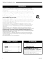
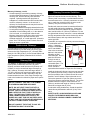
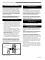
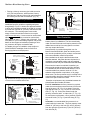
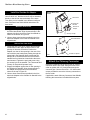
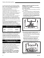
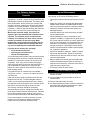
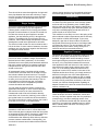
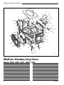
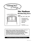
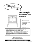
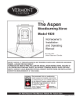
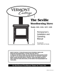
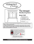
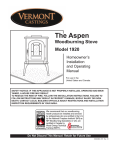
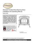
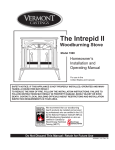
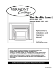
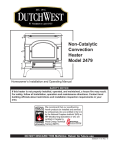
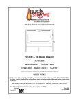
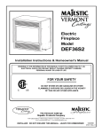
The Madison
Woodburning Stove
Models
1655, 1656, 1657, 1658, 1659
Homeowner’s
Installation and
Operating
Manual
For use in the
United States and Canada
SAFETY NOTICE: IF THIS APPLIANCE IS NOT PROPERLY INSTALLED,
OPERATED AND MAINTAINED, A HOUSE FIRE MAY RESULT.
TO REDUCE THE RISK OF FIRE, FOLLOW THE INSTALLATION
INSTRUCTIONS. FAILURE TO FOLLOW INSTRUCTIONS MAY RESULT
IN PROPERTY DAMAGE, BODILY INJURY OR EVEN DEATH. CONTACT
LOCAL BUILDING OFFICIALS ABOUT RESTRICTIONS AND
INSTALLATION INSPECTION REQUIREMENTS IN YOUR AREA.
CFM Specialty Home Products
410 Admiral Blvd. • Mississauga, Ontario, Canada L5T 2N6 • 905-670-7777
www.majesticproducts.com • www.vermontcastings.com
Do Not Discard This Manual: Retain for Future Use
30001453 4/04 Rev. 3
Madison Woodburning Stove
Introduction
Thank you for choosing a Vermont Castings Madison to meet your heating needs. We're
confident you will find the Madison to be an effective woodburning heater incorporating
modern, non-catalytic combustion technology with the classic aesthetic appeal of its Vermont
Castings lineage.
The Madison achieves high-efficiency through precisely calibrated delivery of primary and
secondary air into a refractory-insulated firebox. Properly operated and maintained according
to the guidelines in this manual, your Madison will provide safe, dependable, and economical
heating for years to come.
The Madison Model 1655 Series has been tested and is listed by Canadian Standards
Association (CSA). The test standards are ANSI/UL-1482 for the United States and ULC
S627 and CAN/CSA B366.2 for Canada.
The Madison Model 1655 Series is listed for burning wood fuel only. Do not burn other fuels.
C
US
The Madison Model 1655 Series is approved for installation in manufactured (mobile) homes
in the United States only, using the optional Mobile Home Kit #1894 in accordance with the
instructions in that kit an any local codes.
The Madison Model 1655 Series complies with the standards set forth by the Federal
Environmental Protection Agency, 40 CFR Part 60.532(b)(2), as stated on the permanent
label attached to each stove. The Madison Model 1655 Series meets Washington State
requirements.
We recommend that you hire a professional, solid-fuel stove technician to install your
Madison, or to advise you on the installation should you attempt to install it yourself. Consult
the authority having local jurisdiction (such as a municipal building department, fire
department, fire prevention bureau, etc.) before installation to determine the need for a
building permit. Also, consult your insurance agent to be sure your installation complies with
specific requirements that may vary locally.
In addition to directions on installation and operation, this manual includes directions on
maintenance and assembly. Please read this entire manual before you install or operate
your new room heater.
Save These Instructions For Future Reference.
Table of Contents
Specifications ..................................... 3
Installation Requirements .................. 4
Clearances ......................................... 12
Assembly ........................................... 15
Operation ........................................... 17
Maintenance ...................................... 20
Draft Management .............................22
Parts List ............................................25
2
Accessories
#1891 Outside Air Kit
#1892 Bottom Heat Shield Kit
#1893 Rear Heat Shield Kit
#1894 Mobile Home Kit
Proposition 65 Warning: Fuels used in gas,
woodburning or oil fired appliances, and the products
of combustion of such fuels, contain chemicals
known to the State of California to cause cancer, birth
defects and other reproductive harm.
California Health & Safety Code Sec. 25249.6
30001453
Madison Woodburning Stove
Specifications
Madison, Model 1655 Series
Range of Heat Output ............... 11,300 - 39,700 BTU’s
Maximum heat output ......................... 39,700 Btu’s/hr.1
Area heated ..................................... Up to 1600 sq. ft.2,
EPA emissions ratings, g/h, non-catalytic .............. 3.33
Fuel size/type ................................... 18” (457mm) logs
Loading ..................................................... Front & Side
Chimney connector ..................... 6” (152mm) diameter
Chimney flue size ....................... 6” (152mm) minimum
Flue exit position ........................................ Top or Rear
Primary air ... Manually set, thermostatically maintained
Ash handling system ..................... Removable ash pan
Glass panel ........................ High-temperature Infra-red
Weight ............................................................... 420lbs.
Width (Left leg - Right leg) ....................... 29” (737mm)
Depth (Front Plate - Flue Collar) .............. 25” (635mm)
Height ....................................................... 28” (711mm)
1
This value can vary depending on how the stove is
operated, the type and moisture content of the fuel
used, as well as the design, construction and climatic
location of your home. Figures shown are based on
maximum fuel consumption obtained under laboratory
conditions and on average efficiencies.
2
These values are based on operation in building codeconforming homes under typical winter climate conditions in New England. If your home is of nonstandard
construction (e.g., unusually well insulated, not insulated, built under ground, etc.) or if you live in a more
severe or more temperate climate, these figures may
not apply. Since so many variables affect performance,
consult your Vermont Castings authorized dealer to
determine realistic expectations for your home.
3
Under specific conditions used during EPA emissions
testing.
Drawings not to scale.
25"
(635mm)
28”
(710mm)
24³⁄₄”
(630mm)
18”
(470mm)
29”
(740mm)
1128
Fig. 1
Madison 1655 dimensions.
30001453
3
Madison Woodburning Stove
Installation
SAFETY NOTICE: If your stove is not properly
installed, operated and maintained, a house fire
may result. For safety, follow all installation,
operation and maintenance directions. Contact
local building officials about restrictions and
installation inspection requirements in your area.
Before you begin an installation, review your plans to
be certain that:
• Your stove and chimney connector will be far
•
•
enough from combustible material to meet all
clearance requirements.
The floor protector is large enough and is constructed properly to meet all requirements.
You have all necessary permits from local authorities.
Your local building official is the final authority for
approving your installation as safe and determining
that it meets local and state codes.
The metal label permanently attached to the back of
the stove indicates that the Madison has been tested to
current UL and ULC standards by CSA. Clearance and
installation information is also printed on the label.
Local authorities generally will accept the label as
evidence that, when the stove is installed according to
the information on the label and in this manual, the
installation meets codes and can be approved. Codes,
however, vary in different areas. Before starting the
installation, review your plans with the local building
authority. Your local dealer can provide any additional
information needed.
For any unresolved questions about installation, refer
to the National Fire Protection Association’s publication
ANSI/NFPA 211–1988 Standard for Chimneys, Fireplaces, Vents and Solid Fuel Burning Appliances. In
Canada, the equivalent publication is CSA CAN-B365,
Installation Code for Solid Fuel Burning Appliances and
Equipment. These standards are the bases for many
national codes. They are nationally recognized and are
accepted by most local authorities. Your local dealer or
your local building official may have a copy of these
regulations.
IMPORTANT: Failure to follow these installation
instructions may result in a dangerous situation,
including a chimney or house fire. Follow all
instructions exactly and do not allow makeshift
compromises to endanger property and personal
safety.
Chimneys
Your stove must be connected either to a sound
masonry chimney that meets local codes, to a relined
masonry chimney that meets local codes, or to an
approved prefabricated metal chimney. Whichever of
those types you use, the chimney and chimney connector must be in good condition and kept clean.
If you use an existing masonry chimney, it must be
inspected to ensure safe condition before the stove is
installed. Your local professional chimney sweep,
building inspector, or fire department official will be
able to make the inspection or direct you to someone
who can.
The chimney should extend at least 3' (914mm) above
the highest point where it passes through a roof, and at
least 2' (610mm) higher than any portion of a building
within 10' (3m).
To assure proper draft and good performance, any
chimney used with this stove should extend at least 16'
(5m) above the flue collar of the stove.
0 To 10’
2’ Min.
3’
Min.
0 To 10’
2’ Min.
3’
Min.
Reference Point
AC617
Fig. 2 The 2'-3'-10' Chimney Rule.
Masonry Chimneys
An existing masonry chimney must be inspected to
confirm that it has a lining. Do not use an unlined
chimney. The chimney also should be examined for
cracks, loose mortar, other signs of deterioration, and
blockage. Repair any defects before the chimney is
used with your stove.
A prefabricated doublewall insulated chimney
A tile-lined
masonry
chimney
ST241
Fig. 3 Standard Chimney Types
4
30001453
Madison Woodburning Stove
Masonry Chimneys, cont'd.
• Unused openings in an existing masonry chimney
must be sealed with masonry to the thickness of the
chimney wall, and the chimney liner should be
repaired. Openings sealed with pie plates or
wallpaper are a hazard and should be sealed with
mortar or refractory cement. In the event of a
chimney fire, flames and smoke may be forced out
of these unused thimbles.
• The chimney should be thoroughly cleaned before use.
• A newly-built masonry chimney must conform to the
standards of local building code, or, in the absence
of a local code, to a recognized national code.
Masonry chimneys must be lined, either with codeapproved masonry or precast refractory tiles,
stainless steel pipe, or a code-approved, "poured-inplace" liner. The chimney clean-out door must seal
tightly to ensure a good draft.
Prefabricated Chimneys
A prefabricated metal chimney must be one that is
tested and listed for use with solid-fuel burning appliances to the High-Temperature (H.T.) Chimney Standard UL-103-1985 (2100° F.) for the United States, and
High Temperature (650°C) Standard ULC S-629 for
Canada.
Chimney Size
This Madison is approved for venting into a masonry
chimney with a nominal flue size of 8" x 8" (203 x
203mm), and into a round flue size of 8" (203mm) or 6"
(152mm). It may be vented into larger chimneys as
well, however, chimneys with liners larger than 8" x
12" (203 x 305mm) may experience rapid cooling of
smoke and reduction in draft, especially if they are
located outside the home. Such large chimneys may
need to be insulated or relined for proper stove performance.
DO NOT CONNECT THIS UNIT TO A CHIMNEY
FLUE SERVING ANOTHER APPLIANCE.
NOTE: DO NOT VENT THIS STOVE INTO A
FACTORY-BUILT (ZERO-CLEARANCE) FIREPLACE. THIS STOVE HAS NOT BEEN TESTED
AND LISTED FOR THAT TYPE OF INSTALLATION. FACTORY-BUILT FIREPLACES AND
THEIR CHIMNEYS ARE SPECIFICALLY DESIGNED AS A UNIT FOR USE AS FIREPLACES.
IT MAY VOID THE LISTING OR BE HAZARDOUS
TO ADAPT THEM FOR ANY OTHER USE.
Chimney Connector Guidelines
A chimney connector is the double-wall or single-wall
pipe that connects the stove to the chimney. The
chimney itself is a masonry or prefabricated structure
that encloses the flue. Chimney connectors are used
only to make the connection from the stove to the
chimney. They are for interior use only.
Double-wall connectors must be tested and listed for
use with solid-fuel burning appliances. Single-wall
connectors should be made of 24 gauge or heavier
steel, and should be 6" (150mm) in diameter. Do not
use galvanized chimney connector; it cannot withstand
the high temperatures that can be reached by smoke
and exhaust gases, and may release toxic fumes
under high heat.
If possible, do not pass the chimney connector through
a combustible wall or
ceiling. If passage
through a combustible
Toward
stove
wall is unavoidable,
refer to the recommendations in the section
following on Wall
Pass-throughs. Do not
pass the connector
Flue gas
direction
through an attic, a
closet or any similar
concealed space. The
ST242
whole chimney conFig. 4 Chimney connector.
nector should be
exposed and accessible for inspection and cleaning.
Install the single wall chimney connector not less than
23" (585mm) from the ceiling. Keep it as short and
direct as possible, with no more than two 90° turns. If
possible, use 45° elbows. Slope horizontal runs of
connectors upward 1/4" per foot (20mm per meter)
going from the stove toward the chimney. The recommended maximum length of a horizontal run is 3’
(914mm), and the total length of chimney connector
should be no longer than 8’ (2.5m).
In cathedral ceiling installations, extend the prefabricated chimney downward to within 8’ (2.5m) of the
stove.
SAFETY NOTE: ALWAYS WEAR GLOVES AND
PROTECTIVE EYEWEAR WHEN DRILLING,
CUTTING OR JOINING CHIMNEY CONNECTOR
SECTIONS .
DO NOT CONNECT THE STOVE TO ANY AIR
DISTRIBUTION DUCT OR SYSTEM.
30001453
5
Madison Woodburning Stove
Double-wall Chimney Connectors
The Madison is approved for installation in the U.S.
and Canada with double-wall chimney connectors that
have been tested and listed for use with solid-fuel
burning appliances by a recognized testing laboratory.
Follow the instructions for assembling and installing
double-wall connectors provided by the manufacturer
of the double-wall chimney. To ease assembly and
help assure safety, use chimney components manufactured by a single source.
NOTE: For installations using double-wall
connectors, minimum clearances must conform to
those listed in the clearance chart on Page 12.
Single-wall Chimney Connectors
• Beginning at the flue collar of the stove, assemble
•
•
•
the chimney connector. Insert the first crimped end
into the stove’s flue collar, and keep each crimped
end pointing toward the stove. Using the holes in
the flue collar as guides, drill 1/8" (3mm) holes in
the bottom of the first section of chimney connector
and secure it to the flue collar with three #10 x 1/2"
sheet metal screws.
Secure each joint between sections of chimney
connector, including telescoping joints, with at least
three sheet metal screws. The predrilled holes in
the top of each section of chimney connector serve
as guides when you drill 1/8" (3mm) holes in the
bottom of the next section.
Secure the chimney connector to the chimney.
Instructions for various installations follow.
Be sure the installed stove and chimney connector are
correct distances from nearby combustible material.
NOTE: Special slip pipes and thimble sleeves that
form telescoping joints between sections of chimney
connector are available to simplify assembly. Slip
pipes eliminate the need to cut individual connector
sections. Consult your local dealer about these special
connector sections.
Thimble Sleeve
Flue
Chimney
Connector
Securing the Single-wall Connector to a
Prefabricated Chimney
Follow the installation instructions of the chimney
manufacturer exactly.
Special adapters are available from your local dealer
to make the connection between the prefabricated
chimney and the chimney connector. The top of such
adapters attach directly to the chimney or to the
chimney’s ceiling support package. The bottom of the
adapter is secured to the chimney connector.
The adapter forms a union between the chimney and
chimney connector that ensures any soot or creosote
falling from the inner walls of the chimney will stay
inside the chimney connector.
Securing the Single-wall Connector to a
Masonry Chimney
The Madison may be connected to either a freestanding masonry chimney or to a fireplace masonry
chimney.
Freestanding Installations
If the chimney connector must pass through a combustible wall to reach the chimney, follow the recommendations for Wall Pass-Through construction on
Pages 7-8.
The opening through the chimney wall to the flue - the
"breech" – must be lined with a ceramic or metal thimble
which is securely cemented in place. (Fig. 5)
A metal pipe section called the “thimble sleeve,”
slightly smaller in diameter than standard connector
and the thimbles, will allow the removal of the chimney
connector system for inspection and cleaning. Thimble
sleeves are available from your local dealer.
To install a thimble sleeve, slide it into the breech until
it is flush with the inner flue wall. Be sure that it does
not extend into the flue passage where it could interfere with the draft.
The thimble sleeve should protrude 1-2" (25-51mm)
into the room. Use furnace cement and thin gasketing
to seal the sleeve in place in the thimble. Secure the
chimney connector to the outer end of the sleeve with
sheet metal screws.
Keep sleeve
end flush with
flue tile
ST243
Fig. 5 The thimble, made of either ceramic or metal, must be
cemented securely in place.
6
30001453
Madison Woodburning Stove
Connection Above the Fireplace
Whenever possible, design the installation so that the
connector does not pass through a combustible wall. If
you must include a wall pass-through in your installation, check with your building inspector before you
begin. Also check with the chimney connector manufacturer for any specific requirements.
clearance
*Note
requirement on
pages 12-13
*
Mantel
ST244a
Fig. 6 If the clearance between the chimney connector and
either the ceiling or the mantel is inadequate, a protective
heat shield is required.
Fire clay liner
Min. 2" (51mm) Chimney
clearance to brick and
combustibles
Masonry
Chimney
constructed
to NFPA
211
A
Consult with your dealer regarding special connection
components available for use as wall pass-throughs.
Use only parts that have been tested and listed for use
as a wall pass-through.
Chimney
connector
A = Minimum 12" (305 mm) brick
construction between liner and
combustible framing materials
ST272
Fig. 7 Masonry Wall Pass-through with single wall
chimney connector.
Figure 7 shows one NFPA-approved method. All
combustible material in the wall is cut away to provide
12" (305mm) clearance to the connector. Brick and
mortar are used to enclose the clearance area.
Min. 9"
230mm
Solid
insulated,
listed factorybuilt chimney
length set flush
with flue
Masonry
Chimney
constructed to
NFPA 211
Alternate methods approved by the NFPA:
Min. 2"
(51mm)
Min. 9"
(230mm)
• Using a section of double-wall chimney with a 9"
(229mm) clearance to combustibles. (Fig. 8)
• Placing a chimney connector pipe inside a steel
double-wall ventilated thimble, which is then separated from combustibles by 6" (152mm) of fiberglass insulating material. (Fig. 9)
30001453
Min. 12"
(305 mm)
Fire clay
liner
A
U.S. Requirements:
The National Fire Protection Association (NFPA) has
established guidelines for use in the United States for
passing chimney connectors through combustible
walls. Many building code inspectors follow these
guidelines.
*
Chimney Flue
Wall Pass-throughs
Chimney Connector
Heat Shield
Chimney Flue
In this installation, the chimney connector enters the
fireplace flue through a thimble located above the
fireplace. (Fig. 6) The liner of the fireplace chimney
should extend at least to the point at which the chimney connector enters the chimney. Follow all the
guidelines for installing a chimney connector into a
freestanding masonry chimney, and pay special
attention to these additional points:
• The stove and chimney connector clearances to
combustible mantel and trim materials are the same
as clearances to combustible walls. If necessary,
use a combination of mantel, trim, and connector
heat shields to provide the required clearances.
Refer to Page 12.
• Double-check connector clearance to the ceiling.
• The fireplace damper must be closed and sealed to
prevent room air from being drawn up the flue which
could reduce performance. However, it must be
possible to reopen the damper to inspect or clean
the chimney.
• Floor protection requirements also apply to fireplace
installations.
ST273
Sheet Steel
Supports
Non-soluble
refractory cement
Chimney
Connector
Air Space
24 ga.Sheet
Steel
Supports
Fig. 8 Wall Pass-through using factory-built insulated
chimney section.
7
Madison Woodburning Stove
• Placing a chimney connector pipe inside a section
Min. 18"
(460mm)
Chimney clearance to sheet steel
supports and combustibles
Canadian Requirements:
In Canada, the Canadian Standards Association has
established specific guidelines regarding wall passthough design. Figure 11 shows one approved method
in which all combustible material in the wall is cut away
to provide the required 18" (457mm) clearance around
the connector. The resulting space must remain
empty. A flush-mounted sheet metal cover may be
used on one side only. If covers must be used on both
sides, each cover must be mounted on noncombustible spacers at least 1" (25mm) clear of the wall. Your
local dealer or your local building inspector can provide
details of other approved methods of passing a chimney connector through a combustible wall.
In Canada, this type of installation must conform to
CAN/CSA-B365, Installation Code for Solid Fuel
Burning Appliances and Equipment.
Chimney clearance to sheet
steel supports and combustibles
2" (51mm) Min.
Steel Thimble
with two 1"
(25mm) Ventilated
Channels
Chimney Flue
Masonry Chimney
constructed to NFPA 211
Min. 6"
(152mm)
Chimney Connector
Glass Fiber
Insulation
24 ga.Sheet
Steel Supports
ST274
Fig. 9 Wall Pass-through using single wall chimney
connector with a ventilated steel thimble.
2" (51mm) Min.
air space
Prefab
Chimney
Section
24 ga. Sheet
Steel Supports
ST275
Chimney Flue
Chimney clearance to sheet steel
supports and combustibles
Chimney
Connector
24 ga.Sheet
Steel Support
24 ga. Sheet
Steel Support
(one side only)
Masonry Chimney
constructed to CAN/CSAB365
ST276
Fig. 11 CSA approved Wall Pass-through.
Floor Protection
A tremendous amount of heat radiates from the
bottom plate of your Madison. The floor area directly
under and around the stove will require protection from
radiant heat as well as from stray sparks or embers
that may escape the firebox.
Heat protection is provided through the use of a
Bottom Heat Shield #1892. Spark and ember protection must be provided by a floor protector constructed
with noncombustible material as specified.
Most installations will require that the bottom heat
shield be attached. Only when the stove is placed on a
completely noncombustible surface such as unpainted
concrete over earth may it be used without the heat shield.
Even when the bottom heat shield is installed, you
must provide special protection to the floor beneath.
For installations with the heat shield attached, use a
noncombustible floor protector such as 1/4” nonasbestos mineral board or equivalent, or 24 gauge
sheet metal. The floor protector may be covered with a
noncombustible decorative material if desired. Do not
obstruct the space under the heater.
Protection requirements vary somewhat between the
United States and Canada as follows:
2" (51mm)
Min.
2" (51mm) Min.
Chimney
Connector
Prefab
Chimney
Section
24 ga. Sheet
Steel Supports
Masonry Chimney
constructed to NFPA 211
Fig. 10 Wall Pass-through with ventilated steel thimble.
8
2" (51mm)
Min.
Min. 18"
(460mm)
Chimney Flue
of 9" (230 mm) diameter, solid-insulated, factorybuilt chimney, with two inches of air space between
the chimney section and combustibles. (Fig. 10)
For U.S. installations the floor protector is required
under the stove and must extend at least 18” from the
front of the stove (“D”, Fig. 12), at least 4” from the
right side and rear (“C”, Fig. 12) and 16” from the left
side (“E”, Fig. 12). It must also extend under the
chimney connector and 2” to either side (“F”, Fig. 12).
To meet these requirements, a floor protector must be
at least 48” wide (“A”,Fig. 12) and 48” deep (“B”,Fig.
12)
In Canada, a noncombustible floor protector is required under the heater also. The floor protector must
extend 18” (457mm) to the front (D), and 8” (203mm)
from the right side (C) and rear (C) and 18” (457mm)
from left side (E).
30001453
Madison Woodburning Stove
To meet these requirements, a floor protector must be
at least 54” (1372mm) wide (“A”,Fig. 12) and 52”
(1320mm) deep (“B”, Fig. 12).
Fireplace Hearth Protection
Do not assume that your fireplace hearth is completely
noncombustible. Many fireplace hearths do not satisfy
the “completely noncombustible” requirement because
the brick or concrete in front of the fireplace opening is
supported by heavy wood framing. (Fig. 13) Because
heat is readily conducted by brick or concrete, it can
easily pass through to the wood. As a result, such
fireplace hearths can be a fire hazard and are considered a combustible floor.
For all fireplace installations, follow the floor protection
guidelines described above.
Keep in mind that many raised hearths will extend less
than the required clearance from the front of the heater
when it is installed. In such cases, sufficient floor
protection as described above must be added in front
of the hearth to satisfy the minimum floor protector
requirement from the front of the stove: 18" (460mm)
from the front in the United States and 18" (460mm)
from the front in Canada.
Hearth rugs do not satisfy the requirements for floor
protection as they are only fire-retardant, not fire proof.
Floor Protection Requirements
Rear Vent
F
Top Vent
Wood framing
requires protection
from radiant heat
ST247a
Fig. 13 Supporting timbers under fireplace hearths are
considered to be combustible.
Clearance to Surrounding
Combustible Materials
When the stove is operating, both the stoveplate and
the chimney connector radiate heat in all directions. A
safe installation requires that adequate clearance be
maintained between the stove and nearby combustible
materials to ensure that those materials do not
overheat.
Clearance is the distance between either your stove or
chimney connector, and nearby walls, floors, the
ceiling, and any other fixed combustible surface. Keep
furnishings and other combustible materials away
from the stove as well. In general, a distance of 48"
(1219mm) must be maintained between the stove and
moveable combustible items such as drying clothes,
furniture, newspapers, firewood, etc. Keep this area
empty of any combustible material.
Safe Ways to Reduce Clearances
C
C
B
E
C
E
C
D
D
A
A
U. S.
A:
B:
C:
D:
E:
F:
48”
48”
4”
18”
16”
10”
Canada
54”
52”
8”
18”
18”
10”
(1372mm)
(1321mm)
(203mm)
(457mm)
(457mm)
(254mm)
The Madison clearance requirements, listed and
diagramed on Pages 12-13, have been established
through testing to UL and ULC standards to meet most
installation configurations. These involve four basic
variables:
• When neither the chimney connector nor the wall
has a heat shield installed.
• When only the chimney connector has a heat
shield installed.
• When only the wall has a heat shield mounted on it.
• When a heat shield is installed on both the
chimney connector and wall.
ST500a
Fig. 12 These dimensions are minimum requirements only.
Use greater dimensions whenever possible.
In general, the greatest clearance is required when the
stove will be positioned with no heat shield near a wall
with no heat shield. The least clearance is required
when both the stove and the wall have heat shields.
Reducing a stove clearance may require installation of
a listed heat shield on the chimney connector as well.
Clearances may be reduced only by means approved
by the regulatory authority, or in accordance with the
clearances listed in this manual.
30001453
9
Madison Woodburning Stove
Wall Shields
Wall shields should be constructed of 24 gauge or
heavier sheet metal, or another noncombustible
material such as 1/2" (13mm) insulation board (Fig. 14)
or common brick "laid on flat," with the 3¹⁄₂" (89mm)
side down.
C
Air must be able to flow between the wall and the
shield. At least 50% of the bottom 1" (25mm) of the
shield should be open and the shield must be open at
the top.
B
A
A
B
Shields must be spaced out from the combustible
surface 1" (25mm) on noncombustible spacers. The
spacers should not be directly behind the stove or
chimney connector.
C
C
A = 48” (1219mm)
B = Max. - C
C = 1” (25mm)
C
ST550
Fig. 15 Parallel installation, vertical chimney connector, two
wall shields.
Air flow
A = 48” (1219mm)
B = 48” (1219mm)
C = 1” (25mm)
Stud wall
framing
Wall shield
A
A
B
Noncombustible
spacers and
fasteners
Shield
B
C
C
ST551
Metal Spacer
Drywall
Fig. 16 Parallel installation with rear wall pass-through, two
wall shields.
Air flow
ST248a
Fig. 14 Approved Wall shield construction
The following examples of wall shield construction
illustrate common designs used to safely achieve
reduced clearances to combustible wall materials.
Parallel installation, vertical chimney connector,
two wall shields. Fig. 15: Reduced clearances for
both rear and side walls. Wall shields may meet at
corner if desired. Shielding for connector is centered
behind connector.
Parallel installation with rear wall pass-through,
two wall shields. Fig. 16: Reduced clearances for
both rear and side walls. Wall shields may meet at
corner if desired. Shielding for connector is centered
behind connector. Wall pass-through must comply with
codes.
Corner installation, vertical chimney connector,
two wall shields. Fig. 17: Reduced side clearances.
Wall shields MUST meet at corner.
Parallel installation with rear exit, rear wall passthrough, rear wall shield. Fig. 18: Reduced
clearances for rear wall. Shielding for connector is
centered behind connector. Wall pass-through must
comply with codes.
10
C
C
A
B
B
A = 48” (1219mm)
B = Max. - C
C = 1” (25mm)
A
C
C
ST552
Fig. 17 Corner installation, vertical chimney connector, two
wall shields.
A = 48” (1219mm)
B = 48” (1219mm)
C = 1” (25mm)
A
B
C
ST564
Fig. 18 Parallel installation, rear wall pass through, rear wall
shield.
30001453
Madison Woodburning Stove
Alcove Installations
Because of their restricted air flow and heat retention
characteristics, specific construction requirements and
special clearances apply to installations into alcoves.
No stove or chimney connector heat shields are used in
alcove installations.
ALCOVE INSTALLATION OF THE MADISON IS NOT
PERMITTED IN CANADA.
Construction Requirements
The following illustrations show noncombustible ceiling
framing and maximum and minimum permitted dimensions for alcove construction.
ST504
Fig. 21 Cutaway perspective of alcove installation.
36"
Max.
7/16” Durock®
(or equivalent)
spaced 1” off
wood studs on
noncombustible
spacers
Use recommended
floor protection
48" Min.
ST502
Fig. 19 Alcove floor plan. Sheetrock on front face butts to
Durock® (or equivalent) alcove lining.
Existing Combustible
Framing
24"
11"
Min.
Metal studs
support 7/16”
Durock® (or
equivalent)
ceiling
36"
Min.
14¹⁄₄"
Joist Shield
(Supplied by
Chimney
Manufacturer)
48" Min.
ST505
Fig. 22 Reflected ceiling plan.
Metal
Stud
Combustible
facing may
overlap metal
studs by only
1”
1” air gap top
and bottom,
on both
sides and
back wall
7/16” Durock® (or
equivalent)
Ceiling support
package
extends 2”
below Durock®
(or equivalent)
ceiling
1” air gap,
top, bottom,
on both
sides and
back wall
65"
62" Min.
to Alcove
Ceiling
INTREPID II
ST503
Fig. 20 Alcove side section.
30001453
NOTE:
From 62” to
65” must be
covered by
a noncombustible
material.
ST506
Fig. 23 Front view: 65” minimum clearance form hearth to
combustibles on front face. Combustible facing may overlap
metal studs by only 1”. It should not extend below the height of
the noncombustible ceiling.
11
Madison Woodburning Stove
Madison 1655 Series Clearance Chart
Use the chart below together with the diagrams on the next page to determine the minimum clearance required for
your particular installation. In any case, it is always advisable to locate the stove as far away from walls as possible in order to take full advantage of the radiant properties of cast iron.
Stove clearances are measured between the cast iron Top Plate of the stove and the combustible surface. Note
that the cast iron back on the Madison protrudes 5” (127mm) out from the stovetop, and will therefore be closer to
the wall than the top of the stove.
Chimney Connector clearances are measured between the connector surface and the combustible surface. For
Douible-wall Chimney Connector, use the manufacturer’s listed clearance specification.
Use NFPA 211 default clearance or manufacturer’s installation specifications for those configurations not tested.
UNPROTECTED SURFACES
Parallel Installation
STOVE CLEARANCE
Side
Rear
PROTECTED SURFACES
Corner
Installation
Corner
Parallel Installation
Side
A 21”
(533mm)
B 24”
(610mm)
C 21”
(533mm)
Top exit, heat shields on stove,
no shields on single wall
connector
Top exit, heat shield on stove,
heat shield on single wall
connector
Top exit, heat shield on stove,
double wall chimney connector
G 21”
(533mm)
H 24”
(610mm)
I 21”
(533mm)
M 21”
(533mm)
N 22”
(559mm)
O 18”
(457mm)
P 12”
(305mm)
Q 14”
(356mm)
R 8”
(203mm)
S 16”
(406mm)
T 12”
(305mm)
U 18”
(457mm)
V 12”
(305mm)
W 11”
(279mm)
X 8”
(203mm)
Rear exit, no heat shields
Y 18”
(457mm)
Z 20”
(508mm)
N/A
AA 12”
(305mm)
BB 15”
(381mm)
N/A
Rear exit, heat shields
CC 16”
(406mm)
DD 18”
(457mm)
N/A
EE 12”
(305mm)
FF 12”
(305mm)
N/A
Without Connector Heat Shields
UNPROTECTED SURFACE / Vertical
J 12”
(305mm)
E 14”
(356mm)
Corner
Top exit, no heat shields
CHIMNEY CONNECTOR
CLEARANCE
D 12”
(305mm)
Rear
Corner
Installation
K 14”
(356mm)
F 10”
(250mm)
L 10”
(250mm)
PROTECTED SURFACE / Vertical
19” (483mm)
13” (330mm)
With Connector Heat Shields
UNPROTECTED SURFACE / Horizontal
Single-wall Connector
FRONT CLEARANCE
TO COMBUSTIBLES*
PROTECTED SURFACE / Horizontal
23” (584mm)
23” (584mm)
ALL INSTALLATIONS
48" (1220mm)
* A distance of 48" must be maintained between the stove and moveable combustible items such as drying
clothes, furniture, firewood, etc.
12
30001453
Madison Woodburning Stove
Madison 1655 Series Clearance Diagram
Top Exit, Bottom Heat Shield always used, floor
protection, minimum 18” (457mm) in front.
UNPROTECTED SURFACES
Stove Installed
Parallel to Wall
PROTECTED
SURFACES
Stove Installed
Parallel to Wall
Stove in Corner
Stove in Corner
Top Exit Installations, no heat shields
C
B
A
F
E
C
D
F
Top Exit Installations, heat shield on stove, no shields on single-wall connector
I
H
G
L
K
J
I
L
Top Exit Installations, heat shield on stove, heat shields on single-wall connector
O
N
M
R
Q
P
O
R
Top Exit Installations, heat shield on stove, double-wall chimney connector
U
T
S
X
W
U
V
X
ST553
30001453
13
Madison Woodburning Stove
Madison 1655 Series Clearance Diagram
Rear Exit Installations, Bottom Heat Shield, floor
protection, minimum 18” (457mm) in front.
UNPROTECTED SURFACES
Stove Installed
Parallel to Wall
PROTECTED
Stove Installed
Parallel to Wall
Stove in Corner
SURFACES
Stove in Corner
Rear Exit Installations, no heat shields
Z
BB
N/A
N/A
Y
AA
Rear Exit Installations, heat shields
DD
FF
CC
EE
ST563
14
30001453
Madison Woodburning Stove
Assembly
You will need the following tools to assemble the Madison:
• 9/16" open end wrench • safety glasses & gloves
• flat head screwdriver
• power drill w/ 1/8" (3mm) bit
• stub handle phillips screwdriver
2. Mount the bottom heat shield to the stove bottom
using the same phillips head screw previously removed. The corners of the shield will butt against the
cast leg locators at each corner of the stove bottom.
Unpack the Stove
1. Remove the shipping straps and plastic wrap.
2. Inspect the stove and contents for shipping damage
or missing parts. Immediately notify your dealer of
any damage. Do not install this stove if any damage
is evident or any parts are missing.
Hardware Bag contents:
• Stove Legs, 4
• 3/8-16 x 1¹⁄₄” hex head Leg Bolts with washers, 4
• Owner's Registration Card
• Touch-up Paint (Porcelain enamel stoves only)
Install Stove Legs
Remove and discard the four large slot-head screws
from the stove bottom. Install the stove legs using the
hex head bolts from the parts bag. Use 3/8” washers
with all four legs; the door handle holder installs on the
right front leg. Position the holder so the hole to accept
the handle hub faces out from the right side of the
stove. Tighten the bolts firmly. CAUTION: Overtightening can strip tapped threads.
ST465
1/4-20 x 1/2” Pan Head Screw
Fig. 25 Attach the Bottom Heat Shield to the boss in the
center of the stove bottom.
Storing the Handle
Use the removable handle to open or close the doors.
After using it, remove the handle so it will not get hot.
Store the handle in the handle holder installed behind
the right front leg. (Fig. 25a)
Bottom Heat Shield
Door Handle Holder
Leg Bolt and
Washer
Leg Bolt and Washer
ST564
Leg Leveller
ST466
Fig. 24 Attach the stove legs with leg levellers.
Install the Bottom Heat Shield
The #1892 Bottom Heat Shield must be used in the
U.S. and Canada in any installation on a floor that is
not comprised of unpainted cement on earth.
1. Remove the 1/4-20x 1/2" phillips screw from the
central mounting boss in the stove bottom. (Fig. 25)
30001453
Fig. 25a Handle holder and heat shield positions.
When Installing Rear Heat Shield
Models 1655, 1656, 1567, 1658, 1659 only.
Remove and retain the factory installed flue collar heat
shield. Loosen two phillips screws, on either side of the
flue collar, approximately one turn each.Slide heat
shield away from the flue collar, then push flue collar
forward and retighten phillips screws.
15
Madison Woodburning Stove
Install the Outside Air Adapter
The optional #1891 Outside Air Adapter provides a
collar to which a 3” diameter air duct may be attached
directly to the air inlet area at the back of the stove.
This option can be installed in two different configurations, with Rear Heat Shield #1893 and without the
heat shield.
Without Rear Heat
Shield
Stove Back
Outside Air
Standoff
With Rear Heat Shield
1. Engage the Adapter against the Air inlet opening in
the Rear Heat Shield. Align clearance holes in the
adapter with pilot holes in the Rear Heat Shield as
shown at the bottom of Figure 26.
2. Use two sheet metal screws provided in the kit to
attach the Adapter to the Rear Heat Shield at the
aligned holes.
Outside Air
Adapter
Primary Air Flap
With Rear Heat Shield
Rear Heat Shield
Without Rear Heat Shield
1. Facing the rear of the stove, loosen the pan head
screw located a the upper left hand corner of the
primary air inlet two revolutions. Position the
Adapter over the air inlet opening in the rear of the
stove with the pan head screw passing through the
slotted tab in the Standoff. Make certain that the
damper tab is located between the stove and the
standoff and is oriented as it was before the screw
was loosened. Tighten the pan head screw using
the access hole in the standoff. The Thermostat and
Primary Air Flap should operate freely.
2. Engage the Adapter against the air inlet opening in
the Outside Air Standoff. Align clearance holes in
the adapter with pilot holes in the Standoff as
shown at the top of Figure 26.
3. Use two sheet metal screws provided in the kit to
attach the Adapter to the Outside Air Standoff at the
aligned holes.
16
ST462
Oustide Air Adpator
Fig. 26 Outside Air Adapter options.
Attach the Chimney Connector
Insert the crimped end of the first section of chimney
connector into the flue collar. Using the holes in the
collar as guides, drill 1/8" (3mm) holes through the
connector pipe. Use the three #10 x 1/2" sheet metal
screws provided to secure the chimney connection to
the flue collar.
If applicable, attach Chimney Connector Heat Shields
following the instructions included with those parts.
30001453
Madison Woodburning Stove
Operation
How the Madison Works
Combustion control is achieved in the Madison through
two separate air delivery systems.
The primary air control lever, located at the left rear
corner of the stove, controls the amount of incoming
primary air for starting, maintaining, and reviving the
fire. More air entering the stove makes the fire burn
hotter and faster, while less air prolongs the burn at a
lower heat level.
For the greatest air supply and maximum heat output
(but the shortest burn time), move the lever to the left
most position. For a fire that will last longer with less
heat, move the lever to the right. You can set the lever
anywhere in between the upper and lower extremes.
DO NOT USE CHEMICALS OR FLUIDS TO
START THE FIRE. DO NOT BURN GARBAGE
OR FLAMMABLE FLUIDS SUCH AS GASOLINE, NAPTHA, OR ENGINE OIL. ALSO,
NEVER USE GASOLINE-TYPE LANTERN
FUEL, KEROSENE, CHARCOAL LIGHTER
FLUID, OR SIMILAR LIQUIDS TO START OR
"FRESHEN UP" A FIRE. KEEP ALL SUCH
LIQUIDS WELL AWAY FROM THE MADISON
WHILE IT IS IN USE.
CAUTION: THE MADISON WILL BE HOT
WHILE IN OPERATION. KEEP CHILDREN,
CLOTHING AND FURNITURE AWAY. CONTACT MAY CAUSE SKIN BURNS.
DO NOT OVERFIRE THIS HEATER.
OVERFIRING MAY CAUSE A HOUSE FIRE,
OR CAN RESULT IN PERMANENT DAMAGE
TO THE STOVE. IF ANY PART OF THE
STOVE GLOWS, YOU ARE OVERFIRING.
The Madison features an automatic thermostat to
ensure an even heat output at any manual setting you
select. As the fuel burns, the thermostat reacts to the
heat radiating from the stove surface and,
consequently, adjusts the air shutter attached to it. As
the fire intensity (and heat output) builds, the
thermostat slowly closes the air shutter, thereby
restricting incoming combustion air. As the fire intensity
then wanes (and heat output lessens), the thermostat
responds and gradually opens the air shutter which
allows more combustion air to again enliven the fire.
This ebb and flow action functions continuously to
prolong the burn cycle until the fuelbed is exhausted.
30001453
Another separate supply of oxygen is delivered to the
upper area of the firebox to support combustion of
gases released from the main fuel bed. This Secondary Air enters the stove through two, unrestricted inlets
and is heated while passing through separate channels
before being delivered through three stainless steel
multi-ported tubes located at the top of the firebox.
Burn Only High-Quality Wood
THE MADISON IS DESIGNED TO BURN NATURAL
WOOD ONLY; DO NOT BURN ANY OTHER FUELS.
You will enjoy the best results when burning wood that
has been adequately air-dried. Avoid burning “green”
wood that has not been properly seasoned. The wood
should be no longer than 18" (457mm) in length,
however, you will find that shorter wood lengths ease
refueling and promote the most efficient combustion.
The best hardwood fuels include oak, maple, beech,
ash, and hickory that has been split, stacked, and airdried outside under cover for at least one year.
For areas that do not have a supply of hardwood,
commonly burned softwoods include tamarack, yellow
pine, white pine, Eastern red cedar, fir, and redwood.
These too should be properly dried.
Keep wood a safe distance from the heater and keep it
out of the areas around the heater used for refueling
and ash removal.
Use the Air Control Setting that Works
Best for You
No single air control setting will be appropriate for
every situation. Settings will differ depending on the
quality of the fuel, the amount of heat desired, and how
long you wish the fire to burn.
The control setting also depends on your particular
installation’s “draft,” or the force that moves air from
the stove up through the chimney. Draft is affected by
such things as the length, type, and location of the
chimney, local geography, nearby obstructions, and
other factors.
Too much draft may cause excessive temperatures in
the Madison, and could even damage it. On the other
hand, too little draft can cause backpuffing into the
room and/or the “plugging” of the chimney.
How do you know if your draft is excessively high or
low? Symptoms of too much draft include an
uncontrollable burn or a glowing-red stove part. A sign
of inadequate draft is smoke leaking into the room
through the stove or chimney connector joints, low
heat, and dirty glass.
17
Madison Woodburning Stove
In newer homes that are well-insulated and weathertight, poor draft may result from insufficient air in the
house. In such cases, a slightly opened window near
the stove on the windward side of the house will
provide the fresh air needed.
A more effective option for delivering ample
combustion air to the stove is to duct air directly from
outdoors to the stove. In fact, in some areas,
provisions for outside combustion air are required in all
new construction. The optional Madison Outside Air
Adapter is available from your dealer.
When you first begin using the stove, pay attention to
the air control settings. You will quickly find that a
specific setting will give you a fixed amount of heat. It
may take some time to determine the amount of heat
and the length of burn you should expect from various
settings.
WARNING: OPERATE THIS STOVE ONLY WITH
THE DOORS FULLY CLOSED.
The Primary Air Inlet must be open when starting a
fire or when refueling.
Step 1. Open the primary air control fully. (Lever at left
most position)
Step 2. Place several sheets of crumpled newspaper
in the stove. Avoid using glossy or colored paper, as
these burn poorly. At the front of the firebox, place
on the paper six or eight pieces of dry kindling split
to a finger-width size, and on the kindling lay two or
three larger sticks of split dry wood approximately 12" (25-51mm) in diameter. (Fig. 27)
Do not for any reason attempt to increase the firing
of your heater by altering the air control
adjustment range outlined in these directions.
Use the following air control settings as a starting point
to help determine the best settings for your installation.
Madison Control Settings
Burn Rate
Primary Air Control
Shutter Position
High
Medium
Left most position
Fully Open
Half Open
Low
Right most position
Fully Closed
Before you begin using the stove, please read the
Appendix on Draft Management, starting on Page 22,
to learn how the characteristics of your particular
installation will affect your stove's performance. You
and the stove are parts of a system; other parts of the
system have a strong effect on performance. You may
need to vary your firing technique to get the results you
desire.
Starting and Maintaining a Fire
ST263
Fig. 27 Start a fire with small, dry kindling.
Step 3. Light the newspaper and close the doors.
Gradually build up the fire by adding a few 3-5" (80120 mm) diameter splits. (Fig. 28) If this is one of
the first few "break-in" fires, let the fire burn brightly,
and then let it die out.
• During the break-in fires, don't let the stove get
hotter than 500°F. (260°C) as measured on an
optional stove-top thermometer. Adjust the air
control lever as necessary to control the fire.
• Some odor from the stove’s hot metal, the paint,
and the cement is normal for the first few fires.
Conditioning Your Stove
Cast iron is extremely strong, but it can be broken with
a sharp blow from a hammer or from the thermal shock
of rapid and extreme temperature change.
The cast plates expand and contract with changes in
temperature. When you first begin using your
Madison, minimize thermal stress by allowing the
plates to adjust gradually during three or four initial
break-in fires following Steps 1- 3.
BURN SOLID WOOD FUEL ONLY, AND BURN IT
DIRECTLY ON THE GRATE. DO NOT ELEVATE
THE FUEL. DO NOT BURN COAL OR OTHER
FUELS.
18
ST264
Fig. 28 Gradually add larger pieces of wood until all the wood
is burning well.
30001453
Madison Woodburning Stove
NOTE: Some chimneys need to be “primed,” or
warmed up, before they will draw sufficiently to
sustain a fire. To correct this situation, roll up a
couple pieces of newspaper, place them on top of
the kindling and toward the back of the stove, light
them, and close the doors. This should heat the
chimney enough to initiate strong draft.
Once the draft is established, open the front doors
and light the rest of the fuel bed at the bottom. Do
not light the main bed of fuel until the chimney
begins drawing.
Step 4. After the stove has been broken-in using Steps
1-3, continue to build the fire gradually. Add larger
wood with a diameter of 3-4" (75-100 mm).
Continue adding split logs of this size to the brisklyburning fire until there is a glowing ember bed at
least 2" (50 mm) deep. A good ember bed is
necessary for proper functioning and may take up
to an hour to establish.
Step 5. Adjust the thermostatic air control for the
desired heat output.
Refuel While the Embers Are Still Hot
Reload the Madison while it is still hot and there are
plenty of glowing embers to re-kindle the fire. Include
some smaller pieces of wood in the new load of fuel to
help the stove return to its operating temperature
quickly. Wear stove gloves, and follow this procedure
when you reload your stove:
Step 1. Open the thermostat lever.
Step 2. Open the doors and check the ash level in the
ash pan. If necessary, dispose of the ashes and
replace the pan.
Step 3. Use a fireplace tool to break up the charcoal
and direct ash through the grate. Pull the charcoal
from the back to the front.
Step 4. Load wood — smaller, split pieces first. Close
the doors. Ideal performance will be achieved by
operating with the air control set in the maximum
(HIGH) positon for several minutes after refueling.
Reset the primary air control for the desired heat
output after the fire is re-established.
30001453
Ash Disposal
Remove ash before it reaches the top of the ash pan.
Check the level at least once a day, and before each
re-fueling. Using stove gloves, pull the ash pan out of
the stove by its handle. Remove the ash pan and
properly dispose of the ashes. Be sure to keep the pan
level during disposal.
Empty the ash pan regularly, typically every one to
three days. The frequency will vary depending on how
you operate your Madison; if you burn more wood at
higher heat output settings, ash will accumulate rapidly.
Dispose of ashes into a metal container with a tightfitting lid, kept outdoors. Put the closed container of
ash on a noncombustible floor or on the ground, well
away from all combustible materials, pending final
disposal. If the ash is disposed of by burial in soil or
otherwise locally dispersed, keep it in the closed
container until all cinders have thoroughly cooled. You
can use wood ash as a garden fertilizer.
CAUTION: Never use your household or shop
vacuum cleaner to remove ash from the stove;
always remove and dispose of the ash properly.
CAUTION: Avoid slamming the stove door or
striking the glass panel. Do not operate the
stove with the glass panel missing, damaged,
or broken. Do not install substitute materials.
See Maintenance section for replacement
instructions.
Smoke Detectors
The use of smoke detectors throughout the home is
strongly advised, if not required by building codes or
insurance regulations. It is a good idea to install a
smoke detector in the living areas and each bedroom.
You may not, however, wish to install a detector in the
immediate vicinity of the stove. Depending on the
sensitivity of the unit, the alarm can be set off while you
are tending the fire or emptying the ashes. If you install
a detector in the same room, locate it as far away from
the stove as possible.
19
Madison Woodburning Stove
Maintenance
Let the fire in the stove go out and allow the stove to
cool completely before beginning any maintenance
procedure.
Care of the Cast Iron Surface
An occasional dusting with a dry rag will keep the
painted cast iron of your Madison looking new.
The stove’s paint can be touched up as needed. First,
clean the areas to be painted with a wire brush. Then,
touch up the stove with high temperature stove paint.
Apply the paint sparingly, and keep in mind that two
light coats of paint are better than a single heavy one.
Care of Porcelain Enamel Finish
Use a dry or slightly damp rag or a soft brush to
remove spills or stains. For difficult jobs that require a
cleaning agent, use only a kitchen appliance cleaner or
polish recommended for use on enamel surfaces.
Cleaning the Glass
Most of the carbon deposits on the glass will burn off
during hot fires. However, the ash residue that
accumulates on the glass surface should be removed
regularly to prevent etching. Follow this procedure to
clean the glass:
• Be sure the glass is completely cool.
• Clean the glass with water or a cleaner made
especially for this purpose. Do not use abrasive
cleaners.
• Rinse the glass thoroughly.
• Dry the glass completely.
Glass Replacement
Replace glass only with CFM Specialty Home Products
glass panels. The glass panel rests on a cushion
provided by a gasket, and is held in place by two clips.
The glass is coated on one side which is slightly
colored. Remove the door from the stove and place it
on a sturdy, level work surface. Use a towel to protect
the porcelain enamel finish.
1. Remove the Retainer Clips. (Two phillips head
screws on each clip).
2. Inspect the Gasket. If the window gasket is in good
condition, you can leave it in place. If you replace it,
use only gasket 1203556. Be sure the channel
around the window opening is clean, and free of
dust.
Place the gasket into the panel inset.
3. Install the Glass. Lay the glass on the inner gasket
with the coated side down, marked “This Side Out”
(toward the outside of the door). Tighten the screws
20
snugly, but loose enough to allow for a little movement of the glass when the stove is in operation.
Overtightening can crack the glass immediately or
cause it to crack if it is unable to expand when hot.
Gasket Replacement
Your Madison uses rope-type fiberglass gaskets to
make a tight seal between some parts. With use,
particularly on those parts that move, gaskets can
become brittle and compressed and can begin to lose
their effectiveness. These will need periodic
replacement.
The sizes of replaceable gasket are listed below, along
with their applications.
Gasket Size
3/8” Fiberglass
Door Gasket - 1203589
Wait until the fire is out and the stove has cooled. Be
sure to follow the standard safety procedure for
working with dusty materials: Wear safety goggles and
a dust mask.
Step 1. Remove the existing gasket by grasping an
end and pulling firmly.
Step 2. Use a wire brush or a screwdriver to clean the
channel of any remaining cement or bits of gasket.
Remove stubborn deposits of cement with a cold chisel
if necessary.
Step 3. Determine the correct length of the appropriate-sized gasket by laying it out in the channel. Allow
an extra 1-2" (25-50 mm), and mark the spot to be cut.
Step 4. Remove the gasket from the channel, place it
on a wood cutting surface, and cut it at the marked
spot with a utility knife.
Twist the ends slightly to discourage the gasket from
unraveling.
Step 5. Lay an unbroken 1/8" (3 mm) bead of gasket
cement in the newly-cleaned channel.
Step 6. Starting at one end, press the gasket into the
channel.
Ensure a good joint where the gasket meets before
trimming any excess. Do not overlap the gasket ends
or leave ends with ragged edges.
Step 7. Press the gasketed part firmly against its
normal mating surface to seat the gasket evenly in its
channel. Close and latch the door to do this; close the
door on a piece of waxed paper to keep the cement
from migrating onto the non-gasketed part, or mask
other parts
Step 8. Clean excess cement from around the channel. Let the cement that holds the new gasket dry
thoroughly.
30001453
Madison Woodburning Stove
The Chimney System
Creosote
Your Madison is designed to reduce creosote buildup
significantly. However, regular chimney inspection and
maintenance must still be performed. For safety, good
stove performance, and to protect your chimney and
chimney connector, inspect your chimney and chimney
connector on a regular schedule. Clean the system if
necessary. Failure to keep the chimney and connector
system clean can result in a serious chimney fire.
When wood is burned slowly, it produces tar,
organic vapors and moisture that combine to form
creosote. The creosote vapors condense in the
relatively cool chimney flue. As a result, creosote
residue accumulates on the flue lining. When
ignited, this creosote makes an extremely hot fire
within the flue system that can damage the chimney and overheat adjacent combustible material.
If you do have a chimney fire, promptly:
• Close the thermostat lever.
• Get everyone out of the house.
• Call the Fire Department.
You should inspect the system every two weeks during
the heating season as part of a regular maintenance
schedule. To inspect the chimney, let the stove cool
completely. Then, using a mirror and a strong light,
sight up through the flue collar into the chimney flue. If
it is not possible to inspect the flue system in this
fashion, the stove must be disconnected to provide
better viewing access.
If a significant layer of creosote has accumulated —
1/8" (3mm) or more — remove it to reduce the risk of
a chimney fire.
Clean the chimney using a brush the same size and
shape as the flue liner. Flexible fiberglass rods are
used to run the brush up and down the liner, causing
any deposits to fall to the bottom of the chimney where
they can be removed through the clean-out door.
The chimney connector should be cleaned by
disconnecting the sections, taking them outside, and
removing any deposits with a stiff wire brush. Reinstall
the connector sections after cleaning, being sure to
secure the individual sections with sheet metal screws.
Annual Maintenance
Perform a thorough cleaning, inspection and repair
each Spring, at the end of the heating season.
• Thoroughly clean the chimney and chimney connector.
• Inspect the chimney for damage and deterioration.
Replace weak sections of prefabricated chimney.
Have a mason make repairs to a masonry chimney.
• Inspect the chimney connector and replace any
damaged sections.
• Clean ash debris from under the primary air plate.
See procedure below.
• Check gasketing for wear or compression, and
replace if necessary. A 'paper test' will guide you on
this. Close and lock the door on a slip of paper and
then try to pull the paper out. If the paper pulls out
with little or no resistance, the gasket isn't snug
enough at that spot. If adjusting the latch doesn't
result in a seal that makes it hard to pull the paper
out, replace the gasketing.
• Check door handle for tightness. Adjust if needed.
• Check heat shield screws. Tighten as necessary.
• Clean dust from the inner sides of bottom, rear and
connector heat shields.
• Remove ashes from the ash pan and replace with
moisture absorbing material (such as cat litter) to
keep the stove interior dry. Close the stove door to
keep cats from using the litter.
• Touch up the paint on black stoves.
Clean the Primary Air Outlet
1. Remove the phillips head screws that retain the
Primary Air Plate.
2. Use a screwdriver to pry the plate out of the cemented seams.
3. Remove ash debris from the cavity.
4. Use high-temperature furnace cement to reseal the
front seam and side seams and replace the plate.
Secure with the phillips head screws.
If you cannot inspect or clean the chimney yourself,
contact your local Vermont Castings’ Authorized
Dealer or hire a professional chimney sweep.
30001453
21
Madison Woodburning Stove
Draft Management
Your stove is only one part of a system that includes
the chimney, the operator, the fuel and the home. The
other parts of the system will affect how well the stove
works. When there is a good match between all the
parts, the stove works well.
Wood stove operation depends on natural (unforced)
draft. Natural draft occurs when exhaust gas is hotter
(and therefore lighter) than the outdoor air at the top of
the chimney. The greater the temperature difference,
the stronger the draft. As the hot exhaust gas rises out
of the chimney it generates suction that draws air into
the stove for combustion. A slow, lazy fire with the
stove’s air inlets fully open indicates a weak draft. A
brisk fire, supported only by air entering the stove
through the normal inlets, indicates a good draft. The
inlets are passive; they regulate how much air can
enter the stove, but they do not move air into it.
The efficiency of a modern woodburning appliance, (in
which the amount of air available for combustion is
regulated), depends on the chimney to keep exhaust
gases warm all the way outdoors. The characteristics
of your chimney - whether it is steel or masonry,
interior or exterior, matched or mismatched to the stove
collar - determine how quickly it will warm up and how
well it will sustain the optimum temperatures necessary
to maintain strong draft and efficient combustion. Here
follows a description of various flue system characteristics and related effects on stove performance.
Masonry Chimney
Although masonry is the traditional material used for
chimney construction, it can have distinct performance
disadvantages when used to vent a controlled-combustion woodstove. Masonry forms an effective ‘heat sink’
- that is, it absorbs and holds heat for long periods of
time. The large mass, however, may take a long time
to become hot enough to sustain a strong draft. The
larger the chimney (in total mass), the longer it will take
to warm up. Cold masonry will actually cool exhaust
gases enough to diminish draft strength. This problem
is compounded if the chimney is located outside the
home or if the chimney flue has a cross-sectional size
larger than the stove outlet.
Steel Chimney
Most factory-made ‘Class A’ steel chimneys have a
layer of insulation around the inner flue. This insulation
keeps the smoke warm and protects the surrounding
structure from the high flue temperatures. Because the
insulation is less dense than masonry, the inner steel
liner warms up more quickly than a masonry chimney.
Although steel chimneys are not as attractive as their
masonry counterparts, they are very durable and
generally outperform masonry.
22
Inside/Outside Location
Because the chimney’s function is to keep the smoke
warm, it is best to locate it inside the house. This
location uses the house as insulation for the flue and
allows some radiant heat release from the flue into the
home. Since an interior chimney does not continuously
lose its heat to the outdoors, it takes less heat from the
stove to get it warm and keep it warm.
Flue Sizing
The flue size for a controlled-combustion appliance
should be based on the cross-sectional volume of the
stove flue outlet. In this case, more is definitely not
better. Hot gases lose heat through expansion; if a
stove with a six-inch flue collar (28 square inch area) is
vented into a 10” x 10” flue, the gases will expand to
over three times their original volume. As gases cool
with expansion, draft strength decreases. If an oversized flue is also outside the house, the heat it absorbs
will be conducted to the outdoor air and the flue will
remain relatively cool.
It is common for a masonry flue to be oversized for the
stove. Such a chimney can take quite a while to warm
up and the stove performance will likely be disappointing. The best solution to an oversize flue problem is the
installation of an insulated steel chimney liner of the
same diameter as the appliance flue outlet. The liner
keeps the exhaust gas warm and the result is a stronger draft. An uninsulated liner is a second choice although the liner will keep the exhaust restricted to its
original volume, the air around the liner will require time
and heat energy to warm up.
Check your local codes. You may be required to install
a flue liner in any oversize or masonry flue.
Pipe & Chimney Layout
Every bend in the flue will act as a brake on the
exhaust as it flows from the firebox to the chimney cap.
The ideal pipe and chimney layout is straight up from
the stove through a completely straight chimney. Use
this layout if at all possible as it will promote optimum
stove performance and simplify maintenance.
If the stovepipe must elbow to enter a chimney, locate
the elbow about midway between the stove top and the
chimney thimble. This configuration lets the smoke
speed up before it must turn, keeps some pipe in the
room for heat transfer, and allows long-term flexibility
for installing a different appliance without relocating the
thimble.
30001453
Madison Woodburning Stove
There should be no more than eight feet of single-wall
stove pipe between the stove and a chimney. Longer
runs can cool the smoke enough to cause draft and
creosote problems. Use double-wall stove pipe for
longer runs.
Single Venting
Your stove requires a dedicated flue. Do not connect
the stove to a flue used by any other appliance.
Chimney draft is a natural form of energy and follows
the path of least resistance. If the stove is vented to a
flue that also serves an open fireplace or another
appliance, the draft will also pull air in through those
avenues. The additional air flow will lower flue temperatures, reduce draft strength and promote creosote
development; overall stove performance will suffer.
The effect is similar to that of a vacuum cleaner with a
hole in the hose. In some extreme instances, the other
appliance can even impose a negative draft and result
in a dangerous draft reversal.
Fuel
Even the best stove installation will not perform well if
poor fuel is used. If available, always use hardwood
that has been air-dried (‘seasoned’) 12-18 months.
Softwood burns more rapidly than hardwood and has a
high resin content conducive to creosote production.
Decayed wood of any type has little heat value and
should not be used.
All unseasoned (‘green’) wood has a high moisture
content. Much of its heat value will be used to evaporate moisture before the wood can burn. This significantly reduces not only the amount of energy available
to warm your home, but also the intensity of the fire
and temperature of the exhaust gas. Incomplete
combustion and cool flue temperatures promote
creosote formation and weak draft.
You can judge the moisture content of wood by its
appearance and weight or use a commercially available moisture meter for an exact measurement.
Unseasoned wood will be a third heavier than dry
wood. Also, look for cracks (‘checking’) in the ends of
the log that result from contraction as the wood dries.
The longer and wider the cracks, the dryer the wood is.
Purchase your fuel from a reputable dealer.
Creosote
Creosote is a by-product of low-temperature stove
operations, weak draft or both. It is a tar that results
when unburned gases condense inside the flue system
at temperatures below 290°F. Creosote is volatile and
can generate chimney fire. All of the installation
characteristics that adversely affect chimney draft also
promote creosote condensation. Consequently, you
can minimize creosote accumulation with an effective
30001453
chimney design and the use of operational techniques
that encourage good draft and complete combustion.
Backpuffing
Backpuffing is a condition that results when the draft is
too weak to pull flue gases out of the chimney system
as fast as the fire is generating more. Volatile gases
build up within the firebox until reaching a density and
temperature at which they ignite. With this ignition, you
may hear a muffled popping sound and see a bit of
smoke forced out of the air inlets.
This condition is most likely to occur in the spring or fall
when moderate outdoor temperatures and low intensity
fires combine to inhibit draft strength. If your stove
backpuffs, open the air inlets to induce a livelier fire
and speed airflow through the stove. Avoid large loads
of firewood at one time. You should always see lively,
dancing flames in the firebox; a lazy, smoky fire is
inefficient and will promote draft problems.
Negative Pressure
Good draft also depends on a sufficient supply of air to
the stove. The chimney cannot pull more air than is
available. Sluggish draft can be caused by a house
that is tight enough to prevent the ready flow of air to
the stove, or by competition between the stove and
other appliances that vent indoor air to the outside; i.e.,
exhaust fans for range hoods, clothes dryers, bathroom, etc. If the chimney draws well when all such
equipment is turned off (or sealed, in the case of the
fireplaces and/or other stoves), you simply need to be
attentive in timing the use of the other appliances. If
you need to crack a nearby window or door to enable
the chimney to pull well, you should install an outsideair intake to bring combustion air directly to the stove.
Consult your Vermont Castings dealer regarding an
adapter to attach to the stove to connect an air duct for
outdoor combustion air.
Conclusion
Woodburning is more an art than a science. Art includes technique and since installations, homes and
fuel vary, the stove operator must also vary technique,
(mostly timing), to achieve satisfying results. Over
time, you will become familiar with the intricacies and
nuances of your particular installation and you will be
able to identify cause and effect in a variety of seasonal circumstances.
23
Madison Woodburning Stove
15
42
30
16
31
6
2
39
23
8
44
12
36
24
25
37
43
26
27
20
35
4
19
33
45
34
11
22
46
3
13
9
10
18
5
7
14 41
40
21
47
1
38
17
29
32
28
1453
CFM Specialty Home Products reserves the right to make changes in design, materials, specifications, prices and discontinue colors and products
at any time, without notice.
Madison Woodburning Stove
Model 1655, 1656, 1657, 1658, 1659
1.
2.
3.
4.
5.
6.
7.
8.
9.
10.
11.
24
Item Description
Bottom, Outer
End, Left
Back
Secondary Manifold, Left
Front
Load Door
Ashlip
Door End Inner Shield
Firebrick (4)
Bottom, Inner
Primary Air Flap
Part Number
30000795
See Chart Pg. 26
30000798
30000802
See Chart Pg. 26
See Chart Pg. 26
See Chart Pg. 26
30000812
1601103
30000799
30000778
12.
13.
14.
15.
16.
17.
18.
19.
20.
21.
22.
Item Description
Fireback
End, Right
Primary Air Manifold
Top
Exhaust Flue
Leg
Door Assy.
Damper Tab
Pan Hd, PH 1/4-20 x 3/8”
Grate
Secondary Manifold, Right
Part Number
30000813
See Chart Pg. 26
30001491
See Chart Pg. 26
See Chart Pg. 26
See Chart Pg. 26
See Page 25
1601488
1200993
30001445
30000801
30001453
Madison Woodburning Stove
Madison Woodburning Stove
15
14
Model 1655, 1656, 1657, 1658, 1659 (continued)
Item Description
23.
24.
25.
26.
27.
28.
29.
30.
31.
32.
33.
34.
35.
36.
37.
38.
39.
40.
41.
42.
43.
44.
45.
46.
47.
Brick Support
Secondary Air Tube (Rear)
Secondary Air Tube (Middle)
Secondary Air Tube (Front)
Friction Spring
Leveller Blt, Hx Hd 1/4-20 x 1” Z
Washer, 1/4 pl 7/8 o.d.
Pan Hd, PH 10-24 x 1” blk
Nut, Square, 1/4-20 Pln
Insert Door Handle, Holder
Latch, Door
Pan Hd, 10-24 x 1/4” Z
Fl Hd, PH 1/4-20 x 1³⁄₄” Blk
Front Handle w/ Shift
Pawl Assy., Ash Door
CS, Hex Hd 1/4-20 x 5/8” Blk
Fl Hd. Allen 1/4-20 x 3/4” Blk
Ashpan Assy.
Cover Plate, Primary Air
Heat Shield, Flue Collar
Thermostat Sub Assy.
Thermostat Cover
Fl Hd, PH 1/4-20 x 2.50 - Blk
Brick, Side/Back
Brick Support Bracket
30000804
30001493
30001494
30001495
1201846
1201745
1202470
1200907
1203329
1600600
1408628
1200996
1200830
5004245
5004025
1201372
30001166
30001167
30001393
30001456
30001390
30001414
30001444
30000969
30000986
Maintenance Kits Available from your Dealer
1884
1876
3427
30001453
Gasket Kit
Thermostat Kit
Gasket Kit for Glass
16
Part Number
2
17
18
1
9
3
10
5
11
7
8
12
4
6
Madison Doors Exploded View
Item Description
Part Number
1. Door, Right
See Chart Pg. 25
2. Door. Left
See Chart Pg. 25
3. Gasket, Fiberglas 3/16 4nd, Blk
1203556
4. Glass, Door, Right
1408629
5. Glass, Door, Left
1408630
6. Glass Retainer
30000474
7. Pan hd, PH 10-24 x 3/8-Z
1200983
8. Hinge Strap, Door -Right Hand
30001222
9. Hinge Strap, Door - Left Hand
30001223
10. Pin, Long, Door
1600547
11. CS, Hex Hd 1/4-20 x 3/8 Gr. 5 Blk
1201337
12. Washer, Flat 1/4-Z
1202474
Fallaway Handle Complete
0004342
14. Handle, Ceramic
1600620
15. Oval Head Slotted Screw 1/4-20 x 3/375 1201294
16. Griddle Opener/Insert Door Handle
1600650
17. Door Handle Assy w/set screw
30001759
18. SS, Soc 7/16-20X1 Cup Pt.-Blk.
1200334
25
Madison Woodburning Stove
Shell Enamel Parts - Madison Model 1655
Part Name
Classic
Green
Top
30000817
30001213
Left Side
30000797
30001211
Right Side
30000796
30001210
Flue Collar
7000969
2310969
Front
30000808
30001212
Ashlip
30000815
30001214
Left Door
Subassembly
30001173
30001241
Left Door Only
30000810
30001216
Right Door
Subassembly
30001172
30001240
Right Door Only 30000809
30001215
Single Leg
30000816
30001218
Load Door
30000811
30001217
26
Moonlight
3001203
30001201
30001200
30001258
30001202
30001204
Sand
30001193
30001191
30001190
7020969
30001192
30001194
Red
30001183
30001181
30001180
2320969
30001182
30001184
Suede Brown
30002599
30002597
30002596
30002607
30002598
30002595
30001237
30001206
30001233
30001196
30001229
30001186
30002605
30002601
30001236
30001205
30001208
30001207
30001232
30001195
30001198
30001197
30001228
30001185
30001188
30001187
30002604
30002600
30002603
30002606
30001453
Madison Woodburning Stove
Warranty
Limited 3 Year Warranty
Any part repaired or replaced during the limited warranty
period will be warranted under the terms of the limited
warranty for a period not to exceed the remaining term of the
original limited warranty or six (6) months, whichever is longer.
recommended in the Owner’s Guide.
4. This warranty does not cover a stove repaired by
someone other than a CFM Specialty Home Products Authorized Dealer.
5. Damage to the unit while in transit is not covered by this
warranty but is subject to a claim against the common carrier.
Contact CFM Specialty Home Products Authorized Dealer
from whom you purchased your stove or CFM Specialty Home
Products if the purchase was direct. (Do not operate the stove
as this may negate the ability to process the claim with the
carrier.)
6. Claims are not valid where the installation does not
conform to local building and fire codes or, in their absence, to
the recommendations in our Owner’s Guide.
7. The salt air environment of coastal areas, or a highhumidity environment, can be corrosive to the porcelain
enamel finish. These conditions can cause rusting of the cast
iron beneath the porcelain enamel finish, which will cause the
porcelain enamel finish to flake off. This warranty does not
cover damage caused by a salt air or high-humidity environment.
8. CFM Specialty Home Products shall have no obligation
to enhance or update any unit once manufactured.
IN NO EVENT SHALL CFM SPECIALTY HOME PRODUCTS BE LIABLE FOR INCIDENTAL AND CONSEQUENTIAL
DAMAGES. ALL IMPLIED WARRANTIES, INCLUDING THE
IMPLIED WARRANTIES OF MERCHANTABILITY AND
FITNESS, ARE LIMITED TO THE DURATION OF THIS
WRITTEN WARRANTY. THIS WARRANTY SUPERCEDES
ALL OTHER ORAL OR WRITTEN WARRANTIES.
Some states do not allow the exclusion or limitations of
incidential and consequential damages or limitations on how
long an implied warranty lasts, so the above limitations may
not apply to you. This warranty gives you specific rights and
you may have other rights which vary from state to state.
Exclusions & Limitations
How to Obtain Service
1. This warranty is transferable; however, proof of original
retail purchase is required.
2. This warranty does not cover misuse of the this stove.
Misuse includes overfiring which will result if the stove is used
in such a manner as to cause one or more of the plates to
glow red. Overfiring can be identified later by warped plates
and areas where the paint pigment has burned off. Overfiring
in enamel fireplaces is identified by bubbling, cracking,
chipping and discoloration of the porcelain enamel finish.
CFM Specialty Home Products offers no warranty on chipping
of enamel surfaces. Inspect your woodburning stove prior to
accepting it for any damage to the enamel.
3. This warranty does not cover misuse of the stove as
described in the Owner’s Guide, nor does it cover any stove
which has been modified unless authorized by a CFM Specialty Home Products representative in writing. This warranty
does not cover damage to the stove caused by burning salt
saturated wood, chemically treated wood, or any fuel not
If a defect is noted within the warranty period, the customer
should contact a CFM Specialty Home Products Authorized
Dealer or CFM Specialty Home Products if the purchase was
direct with the following information:
CFM Specialty Home Products warrants that this woodburning
stove will be free of defects in material and workmanship for a
period of three years from the date you receive it, except that the
catalyst, thermostat assembly, handles, glass door panels,
cement, and gasketing shall be warranted as described below.
Products will repair or replace, at its option, any part
found to be defective upon inspection by a CFM Specialty
Home Products Authorized Dealer. The customer must return
the defective part or the stove, with shipping prepaid, to the
Authorized Dealer or pay for any Authorized Dealer in-home
travel fees or service charges for in-home repair work. It is the
dealer's option whether the repair work will be done in the
customer's home or in the dealer's shop. If, upon inspection,
the damage is found to be the fault of the manufacturer,
repairs will be authorized at no charge to the customer for
parts and/or labor.
Any woodburning stove or part thereof that is repaired or
replaced during the limited warranty period will be warranted
under the terms of the limited warranty for a period not to
exceed the remaining term of the original limited warranty or
six (6) months, whichever is longer.
Limited 1 Year Warranty
The following parts of the woodburning stove are warranted to
be free of defects in material and workmanship for a period of
one year from the date you receive it: The thermostat
assembly, handles, glass door panels, cement, and gasketing.
Any of these items found to be defective will be repaired or
replaced at no charge, upon the return of the part with postage
prepaid to a CFM Specialty Home Products Authorized
Dealer.
30001453
1. Name, address, and telephone number of the
purchaser.
2. Date of purchase.
3. Serial number from the label on the back.
4. Nature of the defect or damage.
5. Any relevant information or circumstances, e.g.,
installation, mode of operation when defect was noted.
A warranty claim will then start in process. CFM Specialty
Home Products reserves the right to withhold final approval of
a warranty claim pending a visual inspection of the defect by
authorized representatives.
27
CFM Specialty Home Products
410 Admiral Blvd. • Mississauga, Ontario, Canada L5T 2N6 • 905-670-7777
www.majesticproducts.com • www.vermontcastings.com
© CFM Specialty Home Products