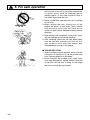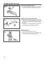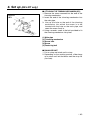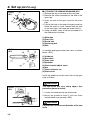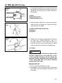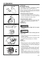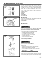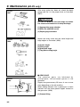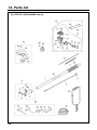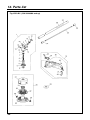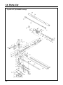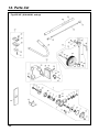
1
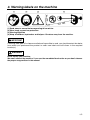
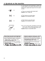
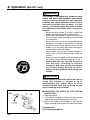
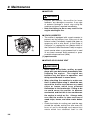
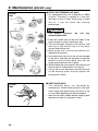
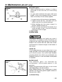
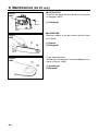
848-J8P-93A0 (603) OWNER / OPERATOR MANUAL EXtreme™ EXZ2401S-BC EX2-BC EX-LRT EX-PS EX-HE WARNING WARNING The engine exhaust from this product contains chemicals known to the State of California to cause cancer, birth defects or other reproductive harm. Before using our products, please read this manual carefully to understand the proper use of your unit. APPLICABLE SERIAL NUMBERS : EXZ-PU 60300000 and up EX2-BC 50200000 and up EX-LRT 000531 and up EX-PS 000000 and up EX-HE 000101 and up ENGINE UNIT 60100000 and up SAFETY FIRST Instructions contained in warnings within this manual marked with a symbol concern critical points which must be taken into consideration to prevent possible serious bodily injury, and for this reason you are requested to read all such instructions carefully and follow them without fail. ■ WARNINGS IN THE MANUAL WARNING This mark indicates instructions which must be followed in order to prevent accidents which could lead to serious bodily injury or death. IMPORTANT This mark indicates instructions which must be followed, or it leads to mechanical failure, breakdown, or damage. NOTE This mark indicates hints or directions useful in the use of the product. 1. 2. 3. 4. 5. 6. 7. 8. 9. 10. 11. 12. CONTENTS Parts location …………………………………3 Specifications …………………………………4 Warning labels on the machine ……………5 Symbols on the machine ……………………6 For safe operation ……………………………7 Set up …………………………………………13 Fuel and chain oil ……………………………19 Operation ……………………………………21 Maintenance …………………………………34 Storage ………………………………………44 Troubleshooting guide ………………………44 Parts list ………………………………………45 1. Parts location 14 1 2 3 13 4 7 6 9 12 5 8 11 10 EX2-BC 16 15 1. 2. 3. 4. 5. 6. 7. 8. 9. 10. 11. 12. 13. 14. 15. 16. 17. 18. 19. 20. 21. 22. 23. 24. 25. 26. 17 EX-LRT 18 19 EX-PS 23 21 20 22 25 EX-HE 26 Loop handle Shoulder strap hanger Ignition switch Throttle cable Throttle lever Throttle set button Drive shaft housing Knob bolt Spark arrester Starter knob Fuel tank Primer pump Choke lever Air cleaner cover Debris guard Gear case Cutting line head Blade Gear case Guide bar Saw chain Chain cover Gear case Wheel Blade guard Blade 24 3 2. Specifications Engine Type······················································································ Air-cooled 2-stroke gasoline Model········································································································ Zenoah GZ23N Displacement ······················································································· 1.5cu-in (23.6cm3) Max. output ····························································· 1.15Hp (0.858kW)at 8000/min-1(rpm) Idle speed··························································································3000±200/min-1(rpm) Fuel ······················································································· Mixture(Gasoline 50 : Oil 1) (when using ZENOAH genuine oil) Carburetor ··················································································· Walbro Diaphragm type Spark plug ····························································································CHAMPION RZ7C Fuel tank capacity·······························································································21.3 fl.oz (0.63 ) Durability period··················································································································300hrs. ■ EX2-BC Overall size(LxWxH)························································ 70.5(1790)x9.8(250)x12.2(310) in(mm) Dry weight w/o acc.······························································································· 11.5 lbs (5.2kg) Transmission··········································································· Centrifugal clutch, Rigid driveshaft Reduction ratio ····················································································································· 1.462 Cutting head rotating direction ················································ Counter-clockwise(Operator view) ■ EX-LRT Overall size(LxWxH)························································ 90.1(2300)x9.8(250)x12.2(310) in(mm) Dry weight w/o acc.································································································ 13.4 lbs(6.1kg) Transmission··········································································· Centrifugal clutch, Rigid driveshaft Reduction ratio ························································································································· 4.0 Cutting head Type···········································································Reciprocating Double blade Tooth··········································································································28teeth Pitch ···················································································································30 Effective cut width ··············································································16 in (40cm) Angle adjust range ··················90°(±45° from cutting head position aligned shaft) ■ EX-PS Overall size(LxWxH)························································ 83.9(2100)x9.8(250)x12.2(310) in(mm) Dry weight w/o bar and chain ············································································ 11.1 lbs (5.05 kg) Transmission··········································································· Centrifugal clutch, Rigid driveshaft Reduction ratio ······················································································································· 0.94 Cutting head Guide bar : Type······································· OREGON DOUBLE GUARD 109666 : Size ·········································································· 12(300) in(mm) Saw chain : Type ································································· OREGON 90SG44X : pitch x guage ······································ 3/8x0.042(9.53x1.07) in(mm) Sprocket············································································································ 7T Oil pump ··························································································· Plunger type ■ EX-HE Overall size(LxWxH)······················································ 72.4(1810)x18.1(450)x15.1(377) in(mm) Dry weight w/o acc.······························································································· 14.5 lbs (7.2kg) Transmission ············································ Centrifugal clutch, Rigid driveshaft, Bevel gears(Angle:90 deg.) Reduction ratio ·········································································································· 2.538(33.13) Blade length ······································································································· 7.87(200) in(mm) Specifications are subject to change without notice. 4 3. Warning labels on the machine (1) Read owner's manual before operating this machine. (2) Wear head, eye and ear protection. (3) Warning/Attention (4) Keep all children, bystanders and helpers 15 meters away from the machine. IMPORTANT If warning label peel off or become soiled and impossible to read, you should contact the dealer from which you purchased the product to order new labels and affix them in the required location(s). WARNING Never modify your machine. We won't warrant the machine, if you use the remodeled brushcutter or you don't observe the proper usage written in the manual. 5 4. Symbols on the machine For safe operation and maintenance, symbols are carved in relief on the machine. According to these indications, please be careful not to make a mistake. (a) The port to refuel the "MIX GASOLINE" Position: FUEL TANK CAP (b) The direction to close the choke Position: AIR CLEANER COVER (c) The direction to open the choke Position: AIR CLEANER COVER (d) If you turn the rod by screwdriver follow the arrow to the “MAX” position, the chain oil flow more, and if you turn to the “MIN” position, less. Position: Bottom of the GEAR CASE IMPORTANT ENGINE INFORMATION THIS ENGINE MEETS U.S. EPA PH2 AND 2006 CALIFORNIA EMISSION REGULATIONS FOR SI SORE’s. COMPLIANCE PERIOD : CATEGORY A ENGINE FAMILY : 6KZXS.0244XY ; EM ENGINE DISPLACEMENT : 24cc REFER TO OWNER’S MANUAL FOR MAINTENANCE SPECIFICATIONS AND ADJUSTMENTS. MANUFACTURED: MADE IN JAPAN 6 INFORMATION IMPORTANTE CONCERNANT LE MOTEUR CE MOTEUR EST CONFORME AUX REGLEMENTS SUR LES EMISIONS DE GAZ U.S. EPA PH2 ET 2006 DE LA CALIFORNIE POUR UNE PERIODE DE CONFORMITE SI SORE: CATEGORIE A TYPE DE MOTEUR : 6KZXS.0244XY ; EM CYLINDREE DU MOTEUR : 24 cc SE REFERER AU MANUEL DE L’UTILISATEUR POUR LES SPECIFICATIONS D’ENTRETIEN ET LES REGLAGES. FABRIQUE PAR : MADE IN JAPAN 5. For safe operation 1. Read this manual carefully until you completely understand and follow all safety and operating instructions. 2. Keep this manual handy so that you may refer to it later whenever any questions arise. Also note, if you have any questions which cannot be answered herein, contact the dealer from whom you purchased the product. 3. Always be sure to include this manual when selling, lending, or otherwise transferring the ownership of this product. 4. Never allow children or anyone unable to fully understand the directions given in the manual to use the machine. ■ WORKING CONDITION 1. When using the product, you should wear proper clothing and protective equipment. (1) Helmet (2) Ear protectors (3) Protection goggles or face protector (4) Thick work gloves (5) Non-slip-sole work boots 2. And you should carry with you. (1) Attached tools (2) Properly reserved fuel (3) Spare blade (4) Things to notify your working area (rope, warning signs) (5) Whistle (for collaboration or emergency) (6) Hatchet or saw (for removal of obstacles) 3. Do not wear loose clothing, jewelry, short trousers, sandals, or go barefoot. Do not wear anything which might be caught by a moving part of the unit. Secure hair so it is above shoulder length. ■ WORKING CIRCUMSTANCE 1. Never start the engine inside a closed room or building. Exhaust gases contain dangerous carbon monoxide. 2. Never use the product, a. when the ground is slippery or when you can’t maintain a steady posture. 7 5. For safe operation b. At night, at times of heavy fog, or at any other times when your field of vision might be limited and it would be difficult to gain a clear view of the working area. c. During rain storms, during lightning storms, at times of strong or gale-force winds, or at any other times when weather conditions might make it unsafe to use the product. ■ WORKING PLAN 1. You should never use the product when under the influence of alcohol, when suffering from exhaustion or lack of sleep, when suffering from drowsiness as a result of having taken cold medicine or at any other time when a possibility exists that your judgment might be impaired or that you might not be able to operate the product properly and in a safe manner. 2. When planning your work schedule, allow plenty of time to rest. Limit the amount of time over which the product is to be used continuously to somewhere around 30~40 minutes per session, and take 10~20 minutes of rest between work sessions. Also try to keep the total amount of work performed in a single day under 2 hours or less. WARNING 1. If you don’t observe the working time, or working manner (See ■ USING THE PRODUCT), Repetitive Stress Injury(RSI) could occur. If you feel discomfort, redness and swelling of your fingers or any other part of your body, see a doctor before getting worse. 2. To avoid noise complaints, in general, operate product between 8a.m. and 5p.m. on weekdays and 9a.m. to 5p.m. weekends. NOTE Check and follow the local regulations as to sound level and hours of operations for the product. 8 5. For safe operation ■ BEFORE STARTING THE ENGINE 1. The area within a perimeter of 50 feet (15m) of the person using the product should be considered a hazardous area into which no one should enter. If necessary yellow warning rope, warning signs should be placed around the perimeter of the area. When work is to be performed simultaneously by two or more persons, care should also be taken to constantly look around or otherwise check for the presence and locations of other people working so as to maintain a distance between each person sufficient to ensure safety. 2. Check the condition of working area to avoid any accident by hitting hidden obstacles such as stumps, stones, cans, or broken grass. IMPORTANT Remove any obstacle before beginning work. 3. Inspect the entire unit for loose fasteners and fuel leakage. Make sure that the cutting attachment is properly installed and securely fastened. 4. Be sure the debris guard is firmly attached in place. 5. Always use the shoulder strap. Adjust the strap for comfort before starting the engine. The strap should be adjusted so the left hand can comfortably hold the handlebar grip approximately waist high. ■ STARTING THE ENGINE 1. Keep bystanders and animals at least 50feet (15m) away from the operating point. If you are approached, immediately stop the engine. 2. The product is equipped with a centrifugal clutch mechanism, so the cutting attachment could rotate as soon as the engine is started. When starting the engine, place the product onto the ground in a flat clear area and hold it firmly in place so as to ensure that neither the cutting part nor the throttle come into contact with any obstacle when the engine starts. 9 5. For safe operation WARNING Make sure the throttle is at idle position. Never place the throttle into the high speed position or half throttle position (throttle lock position) when starting the engine. 3. After starting the engine, check to make sure that the cutting attachment stops rotating when the throttle is moved fully back to its original position (idle position). If it continues to rotate even after the throttle has been moved fully back, turn off the engine and take the unit to your authorized Red Max servicing dealer for repair. ■ USING THE PRODUCT IMPORTANT Cut only materials recommended by the manufacturer. And use only for tasks explained in the manual. 1. Grip the handles firmly with both hands using your whole hand. Place your feet slightly apart (slightly further apart than the width of your shoulders) so that your weight is distributed evenly across both legs, and always be sure to maintain a steady, even posture while working. 2. Keep cutting attachment below waist level. 3. Maintain the speed of the engine at the level required to perform cutting work, and never raise the speed of the engine above the level necessary. 4. If the unit start to shake or vibrate, turn off the engine and check the whole unit. Do not use it until the trouble has been properly corrected. 5. Keep all parts of your body away from rotating cutting attachment and hot surfaces. 6. Never touch the muffler, spark plug, or other metallic parts of the engine while the engine is in operation or immediately after shutting down the engine. Doing so could result in serious burns or electrical shock. 10 5. For safe operation • IF SOMEONE COMES 1. Guard against hazardous situations at all times. Warn adults to keep pets and children away from the area. Be careful if you are approached. Injury may result from flying debris. 2. If someone calls out or otherwise interrupts you while working, always be sure to turn off the engine before turning around. ■ MAINTENANCE 1. In order to maintain your product in proper working order, perform the maintenance and checking operations described in the manual at regular intervals. 2. Always be sure to turn off the engine before performing any maintenance or checking procedures. WARNING The metallic parts reach high temperatures immediately after stopping the engine. 3. When replacing the cutting attachment or any other part, or when replacing the oil or any lubricant, always be sure to use only RedMax products or products which have been certified by RedMax for use with the RedMax product. 4. In the event that any part must be replaced or any maintenance or repair work not described in this manual must be performed, please contact a representative from the store nearest RedMax authorized servicing dealer for assistance. 5. Do not use any accessory or attachment other than those bearing the RedMax mark and recommended for the unit. 6. Under no circumstances should you ever take apart the product or alter it in any way. Doing so might result in the product becoming damaged during operation or the product becoming unable to operate properly. ■ HANDLING FUEL 1. The engine of the RedMax product is designed to run on a mixed fuel which contains highly flammable gasoline. Never store cans of fuel or 11 5. For safe operation refill the tank of the unit in any place where there is a boiler, stove, wood fire, electrical sparks, welding sparks, or any other source of heat or fire which might ignite the fuel. 2. Never smoke while operating the unit or refilling its fuel tank. 3. When refilling the tank, always turn off the engine and allow it to cool down. Take a careful look around to make sure that there are no sparks or open flames anywhere nearby before refueling. 4. Wipe spilled fuel completely using a dry rag if any fuel spillage occurs during refueling. 5. After refueling, screw the fuel cap back tightly onto the fuel tank and then carry the unit to a spot 10 feet or more away from where it was refueled before turning on the engine. ■ TRANSPORTATION 1. When hand-carrying the product, cover over the cutting part if necessary, lift up the product and carry it paying attention to the blade. 2. Never transport the product over rough roads over long distances by vehicle without removing all fuel from the fuel tank. If doing so, fuel might leak from the tank during transport. 12 6. Set up ■ MOUNTING ENGINE (SE1) 1. Push the driveshaft housing toward the clutch housing and rotate it by hand to check that the driveshaft is engaged with the gears. 2. Insert the driveshaft housing into the clutch housing until it bottoms, and align the positioning holes on the clutch housing and the shaft tube and install the screw. When difficult to engage, twist the engine slightly. 3. Fasten the clamp securely with two screws. SE1 SE2 IMPORTANT Tighten the screws gradually by turns. SE3 ■ CONNECTING THROTTLE WIRE 1. Remove the air cleaner cover. 2. Connect the end of the throttle wire to the joint on the top of the carburetor. (SE2) SE4 (1) ■ CONNECTING SWITCH WIRES (SE3) • Connect the switch wires between the engine and the main unit. Pair the wires of the same color. • Bind switchwires to throttle wire with tie band like figure of SE3. (1) Tie band SE5 ■ INSTALLING HANDLE (EX2-BC, EX-LRT only) (SE4) • Install the handle to the shaft tube and clamp it at a location that is comfortable to you. (1) About 19 inches (48cm) (EX-PS only) (SE5) • Insert the grip to the shaft tube. • Fasten the clamps with screws. SE6 (EX-HE only) (SE6) • Install the J-shaped handle to the shaft tube and clamp at a position best for your job. SE7 (1) ■ JOINT ATTACHMENT (SE7) • Insert the attachment to the main shaft. • Tighten the knob bolt securely. (1) Knob bolt 13 6. Set up (EX2-BC only) EX2-BC SE1 EX2-BC SE2 EX2-BC SE3 14 ■ INSTALLING DEBRIS GUARD • Put the debris guard on the gear box, attach it with the 2 screws and hardware provided. (SE1) ■ INSTALLING CUTTING HEAD (SE2) 1. While locking the gear shaft, by inserting the supplied tool into the upper holder on the gear box, loosen and remove the hexagon nut(lefthanded) 2. Then screw in the cutting head to the gear shaft over the holders. Hand-tighten it securely. ■ BALANCE UNIT 1. Put on strap and attach unit to strap. 2. Slide clamp up or down until unit balances with head just touching on the ground. (SE3) 6. Set up (EX-LRT only) EX-LRT SE1 ■ ATTACHING THE TRIMMING MECHANISM (SE1) 1. Remove the screw screwed into the end of the trimming mechanism. 2. Insert the end of the trimming mechanism into the main pipe. 3. Line up the hole on the end of the trimming mechanism into which the screw is to be inserted with the hole on the main pipe, and screw the screw firmly in. 4. Using a wrench, screw in the bolt provided to fix the trimming mechanism into place. (1) Main pipe (2) Trimming mechanism (3) Screw hole (4) Screw (5) Fastening bolt ■ BALANCE UNIT 1. Put on strap and attach unit to strap. 2. Depending on the working posture, slide clamp up or down until unit balances and the strap fits your body. 15 6. Set up (EX-PS only) EX-PS SE1 (1) (2) (3) (4) (5) ■ ATTACHING THE PRUNING MECHANISM (SE1) 1. Remove the cap on the end of the main pipe. 2. Remove the screw screwed into the end of the gear case. 3. Insert the end of the gear case into the main pipe. 4. Line up the hole on the end of the gear case into which the screw is to be inserted with the hole on the main pipe, and screw the screw firmly in. 5. Using a wrench, screw in the bolt provided to fix the mechanism into place. (1) Main pipe (2) Gear case (3) Screw hole (4) Fastening bolt (5) Bolt EX-PS SE2 A standard package contains the items as shown below. (SE2) (1) Guide bar (2) Saw chain (3) Gase case (4) Sprocket (5) Chain tension adjust screw (6) Nut (7) Chain tensioner nut (8) Chain cover Install the guide bar and the saw chain on the gear case as follows. WARNING EX-PS SE3 The saw chain has very sharp edges. Use protective gloves for safety. 1. Loosen a nut and remove the chain cover. 2. Mount the guide bar then fit the saw chain around the bar and sprocket. (SE3) WARNING Pay attention to the correct direction of the saw chain 16 6. Set up (EX-PS only) EX-PS SE4 3. Fit the chain tensioner nut into the lower hole of the guide bar, then install the chain cover, and fasten the mounting nut to finger tightness. (SE3)(SE4) (1) Hole (2) Moving direction (3) Chain tensioner nut EX-PS SE5 4. Adjust the chain tension by turning the tensioner screw until the tie straps just touch the bottom side of the bar rail. (SE5) (1) Chain tension adjusting screw (a) Loosen (b) Tighten EX-PS SE6 5. Tighten the mounting nut securely with the bar tip held up (SE6)(TORQUE: 8.9~11.7 N.m./90~120 kg-cm). Then check the chain for smooth rotation and correct tension while moving it by hand. If necessary, readjustment. (1) Tighten WARNING It is very important to maintain the proper chain tension. Rapid wear of the guide bar or the chain coming off easily can be caused by improper tension. Especially when using a new chain, take good care of it since it should expand when first used. ■ BALANCE UNIT 1. Put on strap and attach unit to strap. 2. Depending on the working posture, slide clamp up or down until unit balances and the strap fits your body. 17 6. Set up (EX-HE only) EX-HE SE1 1. Insert the driveshaft into the clutch drum, then attach the gearbox to the shaft tube as aligning the positioning holes. Wipe out grease on the tube and the inside of the gearbox. Screw in the lock screw and fasten the clamp bolt firmly. (SE1) (1) Clamp bolt (2) Lock screw EX-HE SE2 EX-HE SE3 2.Install the blade guard to the gear case with the provided 3 screws, then clamp it to the shaft tube with 2 screws. (SE2) 3.Place the blade between the cutter holders (A) and (B) while locking the gear shaft by putting the bar, one of the tools provided, through the key holes on the holder(A) and the gearcase. Use the socket and the screwdriver as shown in the picture below to tighten the blade mounting bolt. (SE3) (1) Blade mounting bolt (Left-handed) (2) Cutter holder (B) (3) Blade (4) Bar (5) Cutter holder (A) EX-HE SE4 4.Split the bracket and install the wheel assembly to the shaft tube and clamp at a position best for your job. (SE4) (1) Bracket 18 7. Fuel and chain oil WARNING • Gasoline is very flammable. Avoid smoking or bringing any flame or sparks near fuel. Make sure to stop the engine and allow it cool before refueling the unit. Select outdoor bare ground for fueling and move at least 3m (10ft) away from the fueling point before starting the engine. • The RedMax engines are lubricated by oil specially formulated for air-cooled 2-cycle gasoline engine use. If RedMax oil is not available, use an anti-oxidant added quality oil expressly labeled for air-cooled 2-cycle engine use. (JASO FC GRADE OIL or ISO EGC GRADE) • Do not use BIA or TCW (2-stroke watercooling type) mixed oil. ■ RECOMMENDED MIXING RATIO GASOLINE 50:OIL 1 (when using ZENOAH genuine oil) 50:1 MIXING CHART GASOLINE gal. 1 2 3 4 5 2-CYCLE OIL fl.oz 2.6 5.2 7.8 10.4 13 GASOLINE liter 2-CYCLE OIL ml 1 20 2 40 3 60 4 80 5 100 • Exhaust emission are controlled by the fundamental engine parameters and components(eq., carburation, ignition timing and port timing) without addition of any major hardware or the introduction of an inert material during combustion. • These engines are certified to operate on unleaded gasoline. • Make sure to use gasoline with a minimum octane number of 89 RON (USA/Canada: 87AL) • If you use a gasoline of a lower octane value than prescribed, there is a danger that the engine temperature may rise and an engine problem such as piston seizing may consequently occur. • Unleaded gasoline is recommended to reduce the contamination of the air for the sake of your health and the environment. • Poor quality gasolines or oils may damage sealing rings, fuel lines or fuel tank of the engine. ■ HOW TO MIX FUEL IMPORTANT Pay attention to agitate carefully. 1. Measure out the quantities of gasoline and oil to be mixed. 2. Put some of the gasoline into a clean, approved fuel container. 3. Pour in all of the oil and agitate well. 4. Pour In the rest of gasoline and agitate 19 7. Fuel and chain oil again for at least one minute. As some oils may be difficult to agitate depending on oil ingredients, sufficient agitation is necessary for the engine to last long. Be careful that, if the agitation is insufficient, there is an increased danger of early piston seizing due to abnormal lean mixture. 5. Put a clear indication on the outside of the container to avoid mixing up with other containers. ■ FUELING THE UNIT 1. Untwist and remove the fuel cap. Keep the cap and inlet of the tank clean. 2. Put fuel into the fuel tank to 80% of the full capacity. 3. Fasten the fuel cap securely and wipe up any fuel spillage around the unit. WARNING after rendering it empty. Next, activate the engine and empty the carburetor of the composite fuel. 6. In the case of scrapping the used mixed oil container, scrap it only at an authorized repository site. NOTE As lot details of quality assurance, read the description in the section Limited Warranty carefully. Moreover, normal wear and change in product with no functional influence are not covered by the warranty. Also, be careful that, if the usage in the instruction manual is not observed as to the mixed gasoline, etc. described therein, it may not be covered by the warranty. ■ CHAIN OIL (EX-PS only) Use motor oil SAE 10W-30 all year round, or SAE 30-40 in summer and SAE 20 in winter. 1. Select bare ground for fueling. 2. Move at least 10feet (3meters) away from the fueling point before starting the engine. 3. Stop the engine before refueling the unit. At that time, be sure to sufficiently agitate the mixed gasoline in the container. NOTE FOR YOUR ENGINE LIFE, AVOID; 1. FUEL WITH NO OIL(RAW GASOLINE) – It will cause severe damage to the internal engine parts very quickly. 2. GASOHOL – It can cause deterioration of rubber and/or plastic parts and disruption of engine lubrication. 3. OIL FOR 4-CYCLE ENGINE USE – It can cause spark plug fouling, exhaust port blocking, or piston ring sticking. 4. Mixed fuels which have been left unused for a period of one month or more may clog the carburetor and result in the engine failing to operate properly. 5. In the case of storing the product for a long period of time, clean the fuel tank 20 Do not use waste or regenerated oil that can cause damage to the oil pump. 8. Operation (EX-HE only) ■ STARTING ENGINE The RedMax stick edger is designed for edging lawn in gardens, parks, roadsides and so on. Before starting the engine, take the operating position and adjust the handle position and the wheel height as necessary. OP1 ADJUSTING HANDLE POSITION • Loosen the handle bracket screws and reposition the handle to your best operating position. Re-tighten the screws. (OP1) OP2 ADJUSTING WHEEL HEIGHT • Loosen the clamp lever and change the wheel height to obtain desired cutting depth. (OP2) (1) Deep cut (2) Shallow cut OP3 WARNING • Never adjust wheel height with the engine running. WARNING The cutting head will start rotating upon the engine starts. 1. Feed fuel into the fuel tank and tighten the cap securely. (OP3)(1) (EX-PS only) Feed the chain oil into the oil tank and tighten the cap securely, too. (OP3)(2) (1) Fuel (2) Chain oil OP4 OP5 (1) (2) (3) 2. Rest the unit on a flat, firm place. Keep the cutting head off the ground and clear of surrounding objects as it will start rotating upon starting of the engine. 3. Push the primer pump several times until overflown fuel flows out in the clear tube. (OP4) 4. Move the choke lever to the closed position. (OP5) 5. Set the ignition switch to the “start” position. While pulling the throttle lever, push the set button, and release the throttle, then the throttle 21 8. Operation lever is in to the “start” position. (OP6) 6. While holding the unit firmly, pull out the starter rope quickly until engine fires. (OP7) (1) choke lever (2) close (3) open (4) ignition switch (5) start (6) stop (7) throttle set button OP6 (5) WARNING (6) (4) (7) OP7 The product is equipped with a centrifugal clutch mechanism, so the cutting attachment begins to rotate as soon as the engine is started by pulling the throttle. When starting the engine, place the product onto the ground in a flat clear area and hold it firmly in place so as to ensure that neither the cutting part nor the throttle come into contact with any obstacle when the engine starts. (OP8) IMPORTANT • Avoid pulling the rope to its end or returning it by releasing the knob. Such actions can cause starter failures. OP8 7. Move the choke lever downward to open the choke. And restart engine. (OP5) 8. Allow the engine to warm up for a several minutes before starting operation. NOTE 1. When restarting the engine immediately after stopping it, leave the choke open. 2. Overchoking can make the engine hard to start due to excess fuel. When the engine failed to start after several attempts, open the choke and repeat pulling the rope, or remove the spark plug and dry it. ■ STOPPING ENGINE (OP6) 1. Release the throttle lever and run the engine for a half minute. 2. Shift the ignition switch to the STOP position. 22 8. Operation IMPORTANT • Except for an emergency, avoid stopping the engine while pulling the throttle lever. ■ ADJUSTING THROTTLE CABLE • The normal play is 1 or 2mm when measured at the carburetor side end. Readjust with the cable adjuster as required. (OP9) (1) cable adjuster OP9 .04 in (1~2mm) (1) ■ ADJUSTING IDLING SPEED (OP10) 1. When the engine tends stop frequently at idling mode, turn the adjusting screw clockwise. 2. When the cutting head keeps rotating after releasing the trigger, turn the adjusting screw counter-clockwise. (1) idle adjusting screw OP10 (1) NOTE • Warm up the engine before adjusting the idling speed. 23 8. Operation (EX2-BC only) ■ CUTTING WORK (LINE HEAD USAGE) WARNING 1. Always wear eye protection such as safety goggles. Never lean over the rotating cutting head. Rocks or other debris could be thrown into eyes and face and cause serious personal injury. 2. Keep the debris guard in place at all times when the unit is operated. EX2-BC OP1 TRIMMING GRASS AND WEEDS • Always remember that the TIP of the line does cutting. You will achieve better results by not crowding the line into the cutting area. Allow the unit to trim at its own pace. 1. Hold the unit so the head is off the ground and is tilted about 20 degrees toward the sweep direction. (OP1) 2. You can avoid thrown debris by sweeping from your left to the right. 3. Use a slow, deliberate action to cut heavy growth. The rate of cutting motion will depend on the material being cut. Heavy growth will require slower action than will light growth. 4. Never swing the unit so hard as you are in danger of losing your balance or control of the unit. 5. Try to control the cutting motion with the hip rather than placing the full workload on the arm and hands. 6. Take precautions to avoid wire, grass and dead, dry, long-stem weeds from wrapping around the head shaft. Such materials can stall the head and cause the clutch to slip, resulting in damage to the clutch system if repeated frequently. ADJUSTING THE LINE LENGTH • Your brushcutters is equipped with a semi- auto type nylon line head that allows the operator to advance the line without stopping the engine. When the line becomes short, lightly tap the head on the ground while running the engine at full throttle. • Each time the head is bumped, the line advance about 1 inch(25.4 mm). For better effect, tap the head on bear ground or hard soil. Avoid bumping in thick, tall grass as the engine may stall by overload. 24 8. Operation (Optional blade usage EX2-BC only) 9” 22-tooth: SST229 9” 24-tooth: SST249 CUTTER APPLICATION CHART 8” 8-tooth: SGB088 9” 8-tooth: SGB089 8” 4-tooth: SGB048 9” 4-tooth: SGB049 Nylon line head Under growth Heavy weeds Light weeds Grass ■ CHOOSE THE BLADE Choose a suitable recommended cutting attachment according to the object to be cut. • When replacing blade always be sure to use products which have been certified by RedMax. WARNING • When sharpening, removing, or reattaching the blade, be sure to wear thick, sturdy gloves and use only proper tools and equipment to prevent injury. EX2-BC OP2 (1) (2) ■ SET UP 1. Detach the line head assembly completely. (OP2) 2. Put on the blade, making the marked side face the holder, put on the outer holders, and fasten the blade with the blade nut. (OP2) (1) Cover: 3540-13283 (2) Holder: 6019-13250 (Attachment) IMPORTANT EX2-BC OP3 Change to the debris guard which is suitable for the metal blade. (OP3) TIGHTENING TORQUE: (1) Guard-A: 5764-24000 (2) Guard: 5766-24110 (3) Bracket: 3250-24120 130~174 in-lbs (14.7~19.6 N.m.) (4) Bolt: 0225-10620 (5) Screw: 0263-30614 (6) Nut: 0280-10605 25 8. Operation (Optional blade usage EX2-BC only) EX2-BC OP4 IMPORTANT Change the loop handle to the J-handle for safe operation. (OP4) (1) Bracket: 3583-14101 (2) J-handle: 6367-14200 ■ STARTING THE ENGINE Please refer 5.For safe operation (P.9~11), 8.Operation (P.21~22). WARNING EX2-BC OP5 EX2-BC OP6 • The product is equipped with a centrifugal clutch mechanism, so the cutting attachment begins to rotate as soon as the engine is started by putting the throttle into the start position. When starting the engine, place the product onto the ground in a flat clear area and hold it firmly in place so as to ensure that neither the cutting part nor the throttle come into contact with any obstacle when the engine starts. (OP5) ■ CUTTING METHOD a) Use the front left side cutting. b) Guide the blade from your right to left with it tilted slightly to your left. (OP6) c) When mowing a wide area, start working from your left end to avoid interference of cut grass. d) The blade may be seized by weeds if the engine speed is too low, or the blade cuts too deep into weeds. Adjust the engine speed and cutting depth according to the condition of object. WARNING • If the grass or other object gets caught in the blade, or if the unit starts to shake or vibrate, turn off the engine and check the whole unit. Change the blade if it has been damaged. • Turn off the engine and make sure the blade has completely stop before checking the blade, and removing any object got caught in. 26 8. Operation (Optional blade usage EX2-BC only) EX2-BC OP7 ■ OPERATION 1. Check the bolt to fasten the blade and be sure the bolt has no fault, and no abrasion. 2. Be sure that the blade and the holder have been fastened according to instruction and the blade turns smoothly without abnormal noise. (OP7) WARNING EX2-BC OP8 • The rotating parts fastened incorrectly may cause serious accident to the operator. • Make sure that the blade is not bent, warped, cracked, broken or damaged. • If you find any error to the blade, discard it and change new one which is certified by RedMax. ■ By using the shoulder strap, hang the unit on your right side. Adjust the strap length so that the cutting head may become parallel to the ground.(OP8) WARNING Make sure to use shoulder strap and debris guard. If not, it is very dangerous when you slip or lose your balance. WARNING ■ CONTROLLING BLADE THRUST • Blade thrust can cause serious personal injury. Carefully study this section. It is important that you understand what causes blade thrust, how you can reduce the chance of blade thrust and how you can remain in control of the unit if blade thrust does occur. 1. What causes blade thrust: • Blade thrust can occur when the moving blade contacts an object that it cannot cut. This contact causes the blade to stop for an instant and then suddenly move or ”bounce” away from the object that was hit. The operator can lose control of the unit and the blade can cause serious personal injury to the operator or any person nearby if the blade contacts any part of the body. 27 8. Operation (Optional blade usage EX2-BC only) 2. How you can reduce the chance of blade thrust: a. Recognize that blade thrust can happen. By understanding and knowing about bounce, you can help eliminate the element of surprise. b. Cut fibrous weeds and grass only. Do not let the blade contact materials it cannot cut such as hard, woody vines and brush or rocks, fences, metal, etc c. Be extra prepared for blade thrust if you must cut where you cannot see the blade making contact such as in areas of dense growth. d. Keep the blade sharp. A dull blade increase the chance of blade thrust. e. Avoid feeding the blade too rapidly. The blade can bounce away from material being cut if the blade is fed faster than its cutting capability. f. Cut only from your right to your left. g. Keep your path of advance clear of material that has been cut and other debris. 3. How you can maintain the best control: a. Keep a good, firm grip on the unit with both hands. A firm grip can help neutralize bounce. Keep your right and left hands completely around the respective handles. b. Keep both feet spread apart in a comfortable stance and yet braced for the possibility that the unit could bounce. Do not overreach. Keep firm footing and balance. 28 8. Operation (Optional blade usage EX2-BC only) EX2-BC OP9 ■ MAINTENANCE BLADE • Check the blade and the fasteners for looseness, cracking, or bending. • Check the cutting edges and reform with a flat file. Point (OP9) : 1. Keep the end corner sharp. 2. Round the root of the edge, using round file. 3. Do not use water when using a grinder. IMPORTANT • It is recommended that filing should be done by professionals. • Especially regarding filing the saw blade, Leave it to the professionals. ■ TRANSPORTING THE UNIT • When you finish cutting in one location and wish to continue work in another spot, turn off the engine, and lift up the unit and carry it paying attention fo the blade. • Never forget to place the protective cover over the blades. • When transporting the unit over long distances, detach the blade fix the unit by ropes. 29 8. Operation (EX-LRT only) WARNING This product is equipped with extremely sharp blades, and when used improperly these blades can be extremely dangerous, and improper handling can cause accidents which may in turn lead to serious injury or death. For this reason, you should always be careful to follow the following instructions when using your trimmer. • Never hold the trimmer in a way in which the blades are pointed towards someone else. • Never allow the blades to come into proximity with your body while the engine of the trimmer is in operation. • Always be sure to turn off the engine before changing the angle of the blades, removing branches which have become stuck in the blades, or at any other time when coming into close proximity with the blades. • Always wear work gloves made of leather or some other sturdy material when using the trimmer. • Always place the blade cover provided with the trimmer over the blades when not in use. • Falling branches may fall onto the face or into the eyes, resulting in injuries, scratches, and cuts, and for this reason you should always be sure to wear a helmet and face protector when using your trimmer. IMPORTANT The thickness of branches which may be cut using this trimmer is limited to up to approximately 3/16" (5mm). Never try to cut branches thicker than this, as doing so may result in damage to the trimmer. EX-LRT OP1 ■ ADJUSTING THE ANGLE OF THE CUTTING BLADES (OP1) 1. Stop the engine. 2. Turn the bolt located on the top of the trimming mechanism counter-clockwise to loosen it. 3. Adjust the angle of the blades to the desired angle, and then fix the bolt firmly back into place. (1) Clamp lever (2) Trimming mechanism 30 8. Operation (EX-PS only) EX-PS OP1 ■ CHECKING OIL SUPPLY After starting the engine, run the chain at medium speed and see if chain oil is scattered off as shown in the figure. (OP1) (1) Chain oil NOTE The oil reservoir has a capacity sufficient to provide about 40 minutes of cutting time (when set to deliver the minimum flow rate, or about as long as you'll get from a tank of fuel). Be sure to refill the oil tank every time when refueling the saw. ■ ADJUSTING OIL FLOW RATE WARNING Never fill the oil reservoir nor adjust the oiler with the engine running. IMPORTANT An increase in bar oil flow rate will speed oil consumption, requiring more frequent checks on the oil reservoir. To ensure sufficient lubrication, It may be necessary to check the oil level more frequently than at fuel tank refills. EX-PS OP2 The guide bar and chain are lubricated automatically by a pump that operates whenever the chain rotates. The pump is set at the factory to deliver a minimum flow rate, but it can be adjusted in the field. A temporary increase in oil flow is often desirable when cutting things like hardwood or wood with a lot of pitch. Adjust the pump as follows: 1. Stop the engine and make sure the stop switch is in the OFF position. 2. Place the unit on its side with the oil reservoir up. (OP2) (1) Oil tank (2) Chain cover 31 8. Operation (EX-PS only) IMPORTANT The oil flow adjusting screw must be pressed in slightly in order to turn. Failure to do so could damage the pump and screw. 3. With a screwdriver, push in on the oil flow rate adjusting screw and turn in the desired direction (there are three incremental settings): (a) Clockwise-decrease lubrication. (b) Counter clockwise-increase lubrication. (c) Middle WARNING • Always wear work gloves made of leather or some other sturdy material when using the polesaw. • Falling branches may fall onto the face or into the eyes, resulting in injuries, scratches, and cuts, and for this reason you should always be sure to wear a helmet and face protector when using your polesaw. 32 8. Operation (EX-HE only) WARNING EX-HE OP1 • Always wear eye protection such as safety goggles. Never lean over the rotating cutting head. Rocks or other debris could be thrown into eyes and face and cause serious personal injury. • Keep the blade guard and the mad guard attached in place at all times when the unit is operated. • Before starting a job, check the area and remove all obstacles and objects that could be thrown by the blade. • Do not adjust the wheel height or try to remove anything entangled to the blade with the engine running. 1. Before starting the engine, adjust the wheel height for desired cutting depth (See page 21). 2. Before starting a job, plan your direction of travel so that you can always hold the edger on you right side and can walk on a hard surface as much as possible. 3. When starting to edge, run the engine at full throttle, and slowly have the blade cut into the edge groove. NOTE • Before edging, make sure the area is soft enough so the blade does not bog down. • Do not move the edger into the work so fast that the engine or blade bogs down. 33 9. Maintenance Maintenance, replacement, or repair of the emission control device and systems may be performed by any non-road engine repair establishment or individual. ENGINE ■ MAINTENANCE CHART every every every 25 50 100 before hours hours hours note use after after after system/compornent procedure fuel leaks, fuel spillage wipe out ✔ fuel tank, air filter, fuel filter inspect/clean ✔ idle adjusting screw spark plug see ■ADJUSTING IDLING SPEED (p.23) ✔ replace carburetor ✔ if necessary clean and readjust plug gap SHAFT CUTTING UNIT cutting parts replace if something's wrong replace, if necessary ✔ ✔ muffler, spark arrester, cylinder exhaust port clean check operation GAP: .025in(0.6~0.7mm) ✔ cylinder fins, intake air cooling vent clean throttle lever, ignition switch replace, if necessary ✔ EX2-BC, EX-LRT, ✔ EX-HE ✔ gear case grease screws/nuts/bolts tighten/replace ✔ debris guard make sure to attach ✔ EX2-BC, EX-HE oiling port clean ✔ EX-PS only guide bar clean ✔ EX-PS only sprocket inspect/replace saw chain inspect/sharp 34 ✔ ✔ ✔ not adjusting screws EX-PS only EX-PS only 9. Maintenance WARNING • Make sure that the engine has stopped and is cool before performing any service to the machine. Contact with moving cutting head or hot muffler may result in a personal injury. MA1 (1) MA2 ■ AIR FILTER • The air filter, if clogged, will reduce the engine performance. Check and clean the filter element in warm, soapy water as required. Dry completely before installing. If the element is broken or shrunk, replace with a new one. (MA1) (1) air filter ■ FUEL FILTER • When the engine runs short of fuel supply, check the fuel cap and the fuel filter for blockage. (MA2) (1) fuel filter (1) MA3 ■ SPARK PLUG • Starting failure and mis-firing are often caused by a fouled spark plug. Clean the spark plug and check that the plug gap is in the correct range. For a replacement plug, use the correct type specified by RedMax. (MA3) • REPLACEMENT PLUG IS A CHAMPION RZ7C. .025 in 0.655mm IMPORTANT • Note that using any spark plug other than those designated may result in the engine failing to operate properly or in the engine becoming overheated and damaged. • To install the spark plug, first turn the plug until it is finger tight, then tighten it a quarter turn more with a socket wrench. TIGHTENING TORQUE: 87~104 in-lbs (9.8~11.8 N.m.) 35 9. Maintenance ■ MUFFLER WARNING • Inspect periodically, the muffler for loose fasteners, any damage or corrosion. If any sign of exhaust leakage is found, stop using the machine and have it repaired immediately. • Note that failing to do so may result in the engine catching on fire. MA4 (1) ■ SPARK ARRESTER • The muffler is equipped with a spark arrester to prevent red hot carbon from flying out of the exhaust outlet. Periodically inspect and clean as necessary with a wire brush. In the State of California it is required by law (Section 4442 of the California Public Resources Code) to equip a spark arrester when a gas powered tool is used in any forest covered, brush covered, or grass covered unimproved land. (MA4) (1) spark arrester ■ INTAKE AIR COOLING VENT WARNING • Never touch the cylinder, muffler, or spark plugs with your bare hands immediately after stopping the engine. The engine can become very hot when in operation, and doing so could result in severe burns. • When checking the machine to make sure that it is okay before using it, check the area around the muffler and remove any wood chips or leaves which have attached themselves to the brushcutter. Failing to do so could cause the muffler to become overheated, and that this in turn could cause the engine to catch on fire. Always make sure that the muffler is clean and free of wood chips, leaves, and other waste before use. • Check the intake air cooling vent and the area around the cylinder cooling fins after every 25 hours of use for blockage, and remove any waste which has attached itself to the 36 9. Maintenance MA5 (1) brushcutter. Note that it is necessary to remove the engine cover shown in (MA5) in order to be able to view the upper part of the cylinder. IMPORTANT (2) • If waste gets stuck and causes blockage around the intake air cooling vent or between the cylinder fins, it may cause the engine to overheat, and that in turn may cause mechanical failure on the part of the brushcutter. (MA6) (1) cylinder (2) intake air cooling vent (back) MA6 ■ PROCEDURES TO BE PERFORMED AFTER EVERY 100 HOURS OF USE 1. Remove the muffler, insert a screwdriver into the vent, and wipe away any carbon buildup. Wipe away any carbon buildup on the muffler exhaust vent and cylinder exhaust port at the same time. 2. Tighten all screws, bolts, and fittings. 3. Check to see if any oil or grease has worked its way in between the clutch lining and drum, and if it has wipe it away using oil-free, lead-free gasoline. 37 9. Maintenance (EX2-BC only) EX2-BC MA1 ■ REFILLING TRIMMING LINE (MA1) 1. For replacement line, use a diameter of .095in (2.4mm). The spool is capable for a line upto 20ft (6m) on the 4” head. Avoid using a larger line as it may cut down the trimming performance. WARNING For safety reasons, metalreinforced line. do not use 2. Pinch the slotted area on the both sides of the spool housing to unhook the bottom cap. 3. Take out the spool and pull off the old line. Fold new line so that one half line is 4.7in.(12cm) shorter than another half. 4. Wind up the line in the correct direction as indicated on the spool. 5. Hook each end of the line in the slot on the edge of the spool, and then put the ends through the eyelets on the housing. Make sure that the spring and the washers are in place. 6. While holding the spool against the housing, pull the line ends to release them from the slot. 7. Line up the slot on the bottom cap with the hook on the housing, press the cap against the housing until it clicks. EX2-BC MA2 38 ■ GEAR CASE (MA2) • The reduction gears are lubricated by multipurpose, lithium-based grease in the gear case. Supply new grease every 25 hours of use or more often depending on the job condition. • Remove the cutter holders before installing new grease to arrange for old grease to exit. 9. Maintenance (EX-LRT only) EX-LRT MA1 ■ BLADES (MA1) • When refilling the tank or resting, it is often a good idea to use the time to oil the cutting blades. • If a gap exists between the upper and lower blades, follow the procedure below to adjust them so that they fit more closely together. 1. Loosen lock nut (A) as shown in the diagram. 2. Tighten screw (B) fully, and then turn onethird to one-half of a rotation backward. 3. While holding onto the screw to keep it in position, tighten the lock nut. 4. Check to make sure that the flat washer (C) is loose enough so that it may be turned by pressing on it with a finger. (1) Upper blade (2) Lower blade NOTE Screwing in the screw too tightly may make it impossible for the blades to move. Conversely, not screwing in the screw tightly enough may make the blades of the trimmer feel dull and cause leaves and branches to become caught in the blades of the trimmer. QUICK TIP If the blades become so worn down that it is no longer possible to eliminate the gap between them, you should contact the authorized RedMax servicing dealer from which you purchased your RedMax® trimmer to have the blades resharpened or replaced. EX-LRT MA2 ■ GEAR CASE The reduction gears are lubricated by multipurpose, lithium-based grease in the gearcase. Supply new grease every 25 hours of use or more often depending on the job condition. When adding lubricant, use a grease gun to insert lubricant into the three grease nipples located on the gear case. (MA2) (1) Grease fitting 39 9. Maintenance (EX-PS only) EX-PS MA1 (1) ■ OILING PORT Dismount the guide bar and check the oiling port for clogging. (MA1) (1) Oiling port EX-PS MA2 ■ GUIDE BAR Remove sawdust in the bar groove and the oiling port. (MA2) (1) Groove (2) Oiling port EX-PS MA3 (Type: Sprocket nose) Grease the nose sprocket from the feeding port on the tip of the bar. (MA3) (1) Grease port (2) Sprocket 40 9. Maintenance (EX-PS only) EX-PS MA4 EX-PS MA5 The bar rail should always be a square. Check for wear of the bar rail. Apply a ruler to the bar and the outside of a cutter. If a gap is observed between them, the rail is normal. Otherwise, the bar rail is worn. Such a bar needs to be corrected or replaced.(MA4) (1) Ruler (2) Gap (3) No gap (4) Chain tilts ■ SPROCKET Check for extensive wear, and replace it when the teeth are worn over 0.3mm. (MA5) (1) Sprocket ■ SAW CHAIN WARNING It is very important for smooth and safe operation to keep the cutters always sharp. EX-PS MA6 Your cutters need to be sharpened when: • Sawdust becomes powder-like. • You need extra force to saw in. • The cut way does not go straight. • Vibration increases. • Fuel consumption increases. Cutter setting standards: WARNING Be sure to wear safety gloves. Before filing: • Make sure the saw chain is held securely. • Make sure the engine is stopped. • Use a round file of proper size for your chain. Chain type : File size : 90SG 5/32 in (4.0mm) Place your file on the cutter and push straight forward. Keep the file position as illustrated. (MA6) 41 9. Maintenance (EX-PS only) EX-PS MA7 After every cutter has been set, check the depth gauge and file it to the proper level as illustrated. (MA7) WARNING Be sure to round off the front edge to reduce the chance of kickback or tie-strap breakage. (1) Appropriate gauge checker (2) Make the shoulder round (3) Depth gauge standard EX-PS MA8 Make sure every cutter has the same length and edge angles as illustrated. (MA8) (4) Cutter length (5) Filing angle (6) Side plate angle (7) Top plate cutting angle EX-PS MA9 ■ GEAR CASE The reduction gears are lubricated by multipurpose, lithium-based grease in the gearcase. Supply new grease every 25 hours of use or more often depending on the job condition. When adding lubricant, use a grease gun to insert lubricant into the three grease nipples located on the gear case. (MA9) (1) Grease fitting 42 9. Maintenance (EX-HE only) MA1 ■ GEAR CASE • The reduction gears are lubricated by multipurpose, lithium-based grease in the gear case. At every 20 hours of use, supply the gear case with new grease. • Remove the cutter holders before installing new grease to arrange for old grease to exit. NOTE • When removing and installing the cutter holder(a), use care not to allow any dirt and dust entering in to the gear case. 43 10. Storage • Aged fuel is one of major causes of engine starting failure. Before storing the unit, empty the fuel tank and run the engine until it uses all the fuel left in the fuel line and the carburetor. Store the unit indoor taking necessary measures for rust prevention. 11. Troubleshooting guide Case 1. Starting failure CHECK fuel tank fuel filter carburetor adjustment screw sparking (no spark) spark plug ➞ ➞ ➞ ➞ ➞ ➞ PROBABLE CAUSES incorrect fuel fuel filter is clogged out of normal range spark plug is fouled/wet plug gap is incorrect disconnected ➞ ➞ ➞ ➞ ➞ ➞ ACTION drain it and with correct fuel clean adjust to normal range clean/dry correct (GAP: 0.6~0.7mm) retighten Case 2. Engine starts but does not keep running/Hard re-starting. CHECK fuel tank carburetor adjustment screw muffler,cylinder (exhaust port) air cleaner cylinder fin, fan cover ➞ ➞ ➞ ➞ ➞ PROBABLE CAUSES incorrect fuel or staled fuel out of normal range carbon is built-up clogged with dust clogged with dust ➞ ➞ ➞ ➞ ➞ ACTION drain it and with correct fuel adjust to normal range wipe away wash clean When your unit seems to need further service, please consult with our RedMax service shop in your area. 44 12. Parts list EXtreme™ EXZ2401S-BC EXZ-PU EX2-BC ENGINE EX-LRT (ATT) EX-PS (ATT) EX-HE (ATT) NOTE : 1. Use KOMATSU ZENOAH genuine parts as specified in the parts list for repair and/or replacement. 2. KOMATSU ZENOAH does not warrant the machines, which have been damaged by the use of any parts other than those specified by the company. 3. When placing parts orders for repair and/or replacement, check if the model name and the serial number are applicable to those specified in the parts list, then use parts number described in the parts list. 4. The contents described in the parts list may change due to improvement. 5. The parts for the machine shall be supplied seven (7) years after the machine is discontinued. [It is possible that some specific parts may be subject to change of their delivery term and list price within the limit of seven (7) years after the machine is discontinued. It is also possible that some parts may be available even after the limit of seven (7) years.] Mar. 2006 APPLICABLE SERIAL NUMBERS : EXZ-PU EX2-BC EX-LRT EX-PS EX-HE 60300000 50200000 000531 000000 000101 and up and up and up and up and up ENGINE UNIT 60100000 and up 45 12. Parts list Fig.1 EXZ-PU (S/N 60300000 and up) 46 Fig.1 EXZ-PU (S/N 60300000 and up) Key# 1 2 3 4 5 6 7 8 9 10 11 12 13 14 15 16 17 18 19 20 21 22 23 24 25 26 27 28 29 30 31 32 33 34 35 36 37 38 39 40 41 42 43 Description Part Number PIPE COMP., ø24x750 848-J8P-5820 SHAFT, 786x7 T3075-12210 SPACER 6036-12250 JOINT, PIPE-ASS’Y T3087-12400 • JOINT T3087-12410 • STOPPER T3087-12600 • KNOBBOLT 6036-12420 • WASHER 01643-30823 • BOLT 01252-30510 • BOLT 3540-13260 GRIP 848-J80-32H2 LEVER COMP. 848-8R2-0344 • LEVER 848-8R2-0314 • • STAY 6110-14410-01 • • COVER 848-8RA-0340 • • LEVER T3002-12202-03 • • SCREW 6110-14410-04 • • NUT 6110-14410-05 • • SHAFT 6110-14410-06 • • SPRING 6110-14410-07 • • SPRING 6110-14410-08 • • BUTTON T3032-14410-09 • • E-RING 6110-14410-10 • CORD (A) black T3002-12220 • CORD (B) red T3002-12230 TUBE T3002-12240 CABLE T3002-83100 HANGER COMP. T3300-17202 SCREW 0263-90520 PLATE-NAME 848-J8P-90R0 HANDLE ASSY 6420-14100 • HANDLE 6420-14311 • CLAMP 6420-14320 • SCREW 0263-90535 STRAP ASSY T3300-17100 TOOL-SET 848-8U0-0110 • SOCKET, 16x17xt27 848-8U1-0040 • SOCKET, 13x16 T3039-91310 • WRENCH 09007-00425 • WRENCH 09007-00528 • BAR 3540-91110 • SPANNER 3540-91120 GOGGLE T3002-91190 Q'ty Key# Description Part Number Q'ty 1 1 1 1 1 1 1 1 1 1 1 1 1 1 1 1 2 2 1 1 1 1 1 1 1 1 1 1 1 1 1 1 1 4 1 1 1 1 1 1 1 1 47 12. Parts list Fig.2 EX2-BC (S/N 50200000 and up) 48 Fig.2 EX2-BC (S/N 50200000 and up) Key# 1 2 3 4 5 6 7 8 9 10 11 12 13 14 15 16 17 18 19 20 21 22 23 24 25 26 27 28 29 30 31 32 33 34 35 36 37 38 Description Part Number GEARCASE ASSY T3195-31001 • GEARCASE 848-B20-62A0 • BEARING 06004-06000 • BEARING 06000-00626 • RING 04065-02612 • SHAFT T3195-13210 • GEAR T3300-93250 • NUT T3002-13260 • PINION T3195-13310 • BEARING 06001-00609 • RING 3210-13330 • RING 04065-02412 • FITTING 3199-13350 • WASHER 01641-20608 • BOLT 0225-00410 • BOLT TORX 4820-13180 • HOLDER (A) T3300-91340 • BOLT TORX 4820-12350 GUARD ASSY T3195-24003 • GUARD COMP. T3195-24103 • • BLADE T3002-24121 • • SCREW TORX T4960-51431 • • NUT 3320-15310 • CLAMP 3520-24120 • BOLT TORX T4950-63000 TAP HEAD COMP. PT104 Plus • CASE T3189-15112 • EYELET T3189-15191 • COVER T3189-15132 • CORD HOLDER T3189-15142 • SPRING T3189-15160 • CORD T3189-15180 HOLDER (B) 6019-13250 PIPE COMP., ø24x750 T3102-12100 SHAFT, 755x7 T3102-12210 SHAFT-JOINT 6036-12241 SPACER 6036-12250 PLATE-NAME 848-J8R-90R0 Q'ty Key# Description Part Number Q'ty 1 1 1 1 1 1 1 1 1 1 1 1 1 1 1 1 1 1 1 1 1 1 1 1 2 1 1 2 1 1 1 1 1 1 1 1 1 1 49 12. Parts list Fig.3 ENGINE UNIT (60100000 and up) 50 Fig.3 ENGINE UNIT (60100000 and up) Key# Q'ty Key# CYLINDER COMP. • COVER, TR-S • COVER, TR-F • GASKET, TR • BOLT 848-F08-1210 848-F08-12C0 848-F08-12D0 848-F08-12E0 4820-16310 1 1 1 2 4 6 7 8 9 10 11 GASKET, base BOLT TORX INSULATOR GASKET, insu GASKET, carb BOLT TORX T1551-12211 4820-12130 848-F08-14A0 848-F08-14B0 848-F08-14C0 T4950-52001 1 4 1 1 1 4 61 62 63 64 65 66 67 68 69 70 71 12 13 14 15 16 17 18 19 20 21 22 23 24 25 26 27 28 29 30 31 32 33 34 35 36 37 38 39 40 41 42 CRANKCASE COMP. • PIN GASKET, case BEARING SEAL SEAL RING BOLT TORX PISTON RING PIN RING BEARING WASHER CRANKSHAFT COMP. NUT KEY ROTOR COIL ASSY • CAP • SPRING • TUBE SPACER BOLT TORX CARBURETOR ASSY • REBUILD KIT • • BODY ASSY • • GASKET KIT • BODY • COVER • PUMP T1551-21101 2629-21130 T1551-21141 06030-06001 4810-21210 1850-21220 04065-02812 4820-13180 848-F08-41A2 848-8C3-4101 1600-41310 1260-41320 T1551-41410 1101-41340 848-F08-4201 1650-43230 1000-43240 4810-71110 848-F08-7131 4810-72111 848-F08-71G0 848-8MX-0700 1260-71261 4820-72150 848-F08-8101 848-F60-0630 1850-81450 4810-06021 1850-81490 1850-81520 1751-81510 1 3 1 2 1 1 1 3 1 2 1 2 1 2 1 1 1 1 1 1 1 1 2 2 1 1 1 1 1 1 1 44 45 46 47 48 49 50 51 52 53 54 • RING • SWIVEL • SCREW • BRACKET • NUT • SCREW • SCREW • WASHER BOLT TORX CLIP MUFFLER ASSY 1751-81130 1881-81140 1752-81110 5500-81120 1751-81180 1918-81170 1850-81530 5500-81160 4820-15310 1950-86120 848-F08-1510 1 1 2 1 1 1 4 1 2 1 1 56 57 58 59 60 • ARRESTER BOLT TORX GASKET, muff PLATE BOLT TORX 4810-15140 4820-15310 848-F08-15C1 848-F00-15D1 4820-12350 1 2 1 1 2 1 2 3 4 5 Description Part Number Description Part Number Q'ty HOUSING ASSY • HOUSING COMP. • • HOUSING • • BRACKET(A) • • BRACKET (B) • • CUSHION • DRUM • RING • BEARING • SNAP RING • BOLT TORX 848-F00-5301 T1551-31100 T1551-31110 T1700-31212 T1700-31221 T1700-31232 848-F30-51A1 04065-02812 T1701-31150 04064-01210 4820-13180 1 1 1 1 1 1 1 1 1 1 2 73 74 75 76 77 78 79 80 81 82 83 84 85 86 87 88 89 90 91 92 93 94 95 96 97 98 99 100 101 102 103 104 105 106 107 108 109 110 111 112 113 114 BOLT TORX COVER, engine BOLT TORX SHOE SPRING SCREW WASHER WASHER CORD COMP. SPARKPLUG (Champion RZ7C) GROMET RECOIL ASSY • REEL • SCREW • SPRING • COLLAR • ARM • ROPE • KNOB • PLATE PULIEY BOLT TORX BODY ASSY • PLATE, choke • LEVER • SCREW ELEMENT COVER ASSY • KNOB TANK ASSY • CAP ASSY • • HOLDER ASSY • • PACKING • • FILTER • • STOPPER • PIPE COMP. • FILTER • CLIP BOLT TORX GUARD, tank LABEL, recoil LABEL, cover 4820-85510 848-F08-31A1 848-815-1002 T1551-51111 4820-51220 1140-51250 1140-51230 1140-51242 T1551-73200 3699-91809 4810-72120 T1551-75100 4500-75120 4500-75150 1850-75130 4500-75180 4500-75190 4810-75160 3330-75421 4810-75170 4500-75210 4820-32120 848-F00-8310 T1512-82130 T1600-82140 T1108-82190 T1551-82170 848-F62-8320 T1108-82220 848-F00-8500 T1015-85202 4500-85300 4500-85220 5601-85260 4820-85260 T1551-85300 3302-85400 1260-85460 4820-85510 T1551-31910 T1551-75410 T1551-31130 4 1 2 2 1 2 2 2 1 1 1 1 1 1 1 1 1 1 1 1 1 4 1 1 1 1 1 1 1 1 1 1 1 1 1 1 1 1 3 1 1 1 118 119 120 121 COVER BOLT PLATE BOLT 4500-81910 4820-12350 848-F08-12G0 4820-12350 1 1 1 2 51 12. Parts list Fig.4 EX-LRT (S/N 000531 and up) 52 Fig.4 EX-LRT (S/N 000531 and up) Key# Description Part Number Q'ty Key# 1 2 3 4 5 6 7 8 9 10 11 12 13 14 15 16 17 18 19 20 21 22 23 24 25 26 27 28 29 30 31 32 33 34 35 36 37 38 39 40 41 42 43 44 45 46 47 48 49 50 51 52 LEVER, clamp WASHER M6 WASHER 6x15x2.0 ANGLE ADJUSTER BOLT M6x12 CASING A SET • CASING A • PLATE GREESE FITTING LABEL SCREW M4x8 COVER SNAP RING BEBEL GEAR SNAP RING BEARING CRANK SHAFT SNAP RING BLADE BEARING 608Z COVER SET • COVER • GASKET • BOLT, M4x12 FELT SCREW WASHER SCREW L17 SCREW M5x20 GUIDE PLATE PLATE NUT M5 NUT M6 WASHER 6x15x2.0 BEARING 608 2RS SNAP RING SHAFT KIT • • SHAFT • • GEAR(B) • • GEAR(C) • • BOSS • • SPRING • • PLATE • • WASHER • • WASHER • NUT M6 • WASHER O-RING P41 SNAP RING BEARING CASING B WASHER 6x15x2.0 6598-13110 0290-20615 6782-13650 6782-13141 0225-10612 6782-13200 ––––––––– 6782-13220 3199-13350 6782-13250 0263-10408 6598-13320 6598-13330 6782-13340 04065-02612 06004-06000 6782-13370 04064-02815 6782-13411 6782-13430 6782-06010 6782-13441 6782-13470 848-A2R-B1C0 6782-13460 3884-11750-10 3880-11780 6598-13510 6598-13530 6782-13540 6782-13550 6782-14470 3880-11790 6782-13650 6598-13430 04065-02212 T4008-06010 ––––––––– ––––––––– T4008-13630 ––––––––– T4008-13650 T4008-13660 T4008-13670 T4008-13680 0280-10605 0290-20615 6598-13620 04065-02612 06004-06000 6782-13710 6782-13650 1 1 1 1 2 1 1 1 3 1 2 1 1 1 1 1 1 1 2 1 1 1 1 4 1 1 4 3 2 1 1 2 4 1 1 1 1 1 1 1 1 1 1 1 1 1 1 1 1 1 1 1 53 54 55 56 57 58 59 60 61 62 63 64 65 66 67 68 69 70 71 72 Description Part Number BOLT M6x12 0225-10612 WASHER 5x10x1.0 6782-13720 BOLT M5x10 848-A20-61D0 BOLT M5x30 3350-21320 JOINT 6782-13810 GEAR SHAFT B 6598-13820 BEARING 6900RS 6782-13830 SNAP RING 04065-02212 BEVEL GEAR 6782-13850 SNAP RING 6598-13330 PACKING 6598-13860 COVER 6598-13871 SCREW M4x8 0263-10410 BLADE COVER 6782-13910 SPACER 848-A20-61Z1 PIPE COMP., ø24x750 T3102-12100 SHAFT, 755x7 T3102-12210 SHAFT-JOINT 6036-12241 SPACER 6036-12250 PLATE-NAME 848-A2H-90R3 Q'ty 1 1 1 1 1 1 2 1 1 1 1 1 2 1 1 1 1 1 1 1 53 12. Parts list Fig.5 EX-PS (S/N 000000 and up) 54 Fig.5 EX-PS (S/N 000000 and up) Key# Description Part Number Q'ty Key# 47 48 1 2 3 4 5 6 7 8 9 10 11 12 13 14 15 16 17 18 19 20 21 22 23 24 25 26 27 28 29 30 31 32 33 34 35 36 37 38 39 40 41 42 43 44 GEAR CASE (L)COMP. 848-A52-6211 • BEARING 06004-06001 GEAR CASE (R)COMP. T3073-13200 • BEARING 06002-00627 BOLT 01252-30512 FITTING 3199-13350 SCREW, tensioner T3073-13310 NUT, tensioner T3073-13320 BOLT 01252-30630 SHIM T3073-13250 BOLT 3245-11350 CHAIN COVER T3073-13510 NUT T3073-13520 WORM GEAR T3073-13560 OIL PUMP ASSY T3073-13550 SCREW 0263-30410 GASKET T3073-13580 OIL PIPE ASSY T3073-13700 • OIL PIPE T3073-13710 • FILTER T3073-13720 OIL TANK ASSY 848-A52-5511 • COLLAR T3073-13820 • VALVE T3073-13830 SCREW T3073-13860 OIL CAP ASSY T3073-13900 • GASKET OIL CAP T3073-13920 GEAR SHAFT T3073-13370 BEVEL, pinion T3073-13380 BEARING 06000-00609 BEARING 06002-00609 SNAP RING 3210-13330 SNAP RING 04065-02412 COLLAR T3073-13530 SPROCKET T3073-13540 LABEL T3073-13590 WASHER T3073-13350 SCREW T3073-13360 BAR 12” (OREGON) 109666 CHAIN (OREGON) 90SG44X PIPE-COMP, ø24x750 T3102-12100 SHAFT, 755x7 T3102-12210 SHAFT-JOINT 6036-12241 SPACER 6036-12250 PLATE-NAME 848-A51-90R3 1 1 1 1 5 1 1 1 1 1 1 1 1 1 1 2 1 1 1 1 1 2 1 2 1 1 1 1 1 1 1 1 1 1 1 1 1 1 1 1 1 1 1 1 46 GRIP 1 6442-11332 Description CLAMP SCREW Part Number 6193-11340 0260-60312 Q'ty 2 2 55 12. Parts list Fig.6 EX-HE (S/N 000101 and up) 56 Fig.6 EX-HE (S/N 000101 and up) Key# Description 1 2 3 4 5 6 7 8 9 10 11 12 13 14 15 16 17 18 19 20 21 22 23 24 25 26 27 28 29 30 31 32 33 34 35 36 37 38 39 40 41 42 43 44 45 46 47 48 49 50 GEARCASE ASSY • GEARCASE • O-RING • BEARING • SEAL • RING • SHAFT • GEAR • PINION • BEARING • BEARING • RING • RING • BOLT • WASHER • WASHER • BOLT • BOLT • COVER • BEARING • BOLT • HOLDER (A) • HOLDER (B) • FITTING • WASHER HANDLE COMP. BRACKET ASSY • BRACKET • CAP-L • CAP-U • BOLT • BOLT GUARD ASSY • GUARD COMP. • • GUARD • • PLATE • • PLATE • • BOLT • CLAMP • BOLT • WASHER • BOLT BLADE COVER WHEEL ASSY • BRACKET • CAP-L • BOLT • LEVER • WHEEL-S ASSY Part Number 6367-13000 6367-13110 6367-13150 06000-06201 3180-13141 04065-03212 3541-13212 6367-13130 6367-13140 06000-00609 06001-00609 04065-02412 3210-13330 3579-33260 3310-43210 01643-30823 01252-30512 3540-13260 6367-13120 06000-06000 3350-31470 3541-13241 3541-13251 3199-13350 01641-20608 6367-14200 3583-14101 3583-14111 3583-14121 3257-14192 01252-30522 01252-30525 6367-24001 6367-24101 6367-24111 6367-24120 6367-24131 0225-30512 5807-24120 01252-30618 0290-20615 3350-31470 6367-15110 T3052-13610 T3052-25001 6367-15230 3583-14121 01252-30522 3956-15340 T3052-25101 Q'ty Key# 1 1 1 1 1 1 1 1 1 1 1 1 1 1 1 1 1 1 1 1 3 1 1 1 1 1 1 1 1 1 2 4 1 1 1 1 1 2 1 2 2 3 1 1 1 1 1 2 1 1 51 52 53 54 55 56 57 58 59 60 61 62 63 Description • • PIPE • • BRACKET • • BOLT • • WHEEL • • BOLT • • WASHER • • PIPE • • CAP PIPE-COMP, ø24x750 SHAFT, 755x7 SHAFT-JOINT SPACER PLATE-NAME Part Number Q'ty 6367-15210 3808-15230 01252-30625 T3052-25150 01010-81055 01642-21016 T3052-25160 T3052-15250 T3105-12100 T3102-12210 6036-12241 6036-12250 848-A44-90R3 1 1 2 1 1 2 1 1 1 1 1 1 1 57 CALIFORNIA EMISSION CONTROL WARRANTY STATEMENT YOUR WARRANTY RIGHTS AND OBLIGATIONS The California Air Resources Board and KOMATSU ZENOAH are pleased to explain the emission control system warranty on your 1995 and later small off-road engine. In California, new small off-road engines must be designed, built and equipped to meet the state’s stringent anti-smog standards. KOMATSU ZENOAH must warrant the emission control system on your small off-road engine for the periods of time listed below provided there has been no abuse, neglect or improper maintenance of your small off-road engine. Your emission control system may include parts such as the carburetor and the ignition system. Where a warrantable condition exists, KOMATSU ZENOAH will repair your small off-road engine at no cost to you including diagnosis, parts and labor. Manufacturer’s warranty coverage: The 1995 and later small off-road engines are warranted for two years. If any emissionrelated part on your engine is defective, the part will be repaired or replaced by KOMATSU ZENOAH. Owner’s warranty responsibilities: – As the small off-road engine owner, you are responsible for the performance of the required maintenance listed in your owner’s manual. KOMATSU ZENOAH recommends that you retain all receipts covering maintenance on your small off-road engine, but KOMATSU ZENOAH can not deny warranty solely for the lack of receipts or for your failure to ensure the performance of all scheduled maintenance. – As the small off-road engine owner, you should be aware, however, that KOMATSU ZENOAH may deny you warranty coverage if your small off-road engine or a part has failed due to abuse, neglect, improper maintenance or unapproved modification. – You are responsible for presenting your small off-road engine to a KOMATSU ZENOAH distribution center as soon as a problem exists. The warranty repairs should be completed in e reasonable amount of time, not to exceed 30 days. If you have any questions regarding your warranty rights and responsibilities, you should contact KOMATSU ZENOAH AMERICA INC. at (770)-381-5147 or you can write to KOMATSU ZENOAH AMERICA INC. 4344 Shackleford Road Suite 500 Norcross, Georgia 30093 RedMax LIMITED WARRANTY EMISSION-RELATED PARTS, FOR TWO (2) YEARS FROM THE DATE OF ORIGINAL DELIVERY OF THE UNIT, KOMATSU ZENOAH AMERICA INC. (THE COMPANY), THROUGH ANY RedMax DEALER, WILL REPAIR OR REPLACE, FREE OF CHARGE, FOR THE ORIGINAL AND EACH SUBSEQUENT PURCHASER, ANY PART OR PARTS FOUND TO BE DEFECTIVE IN MATERIAL AND/OR WORKMANSHIP. EMISSION-RELATED PARTS ARE: THE CARBURETOR ASSY, COIL ASSY, ROTOR, SPARKPLUG, AIR FILTER, FUEL FILTER, INTAKE MANIFOLD, AND THE GASKETS ALL OTHER PARTS EXCEPT ABOVE PARTS, FOR TWO (2) YEARS OF USE, 90 DAYS FOR RENTAL USE, FROM THE DATE OF ORIGINAL PURCHASE, THE COMPANY, THROUGH ANY RedMax DEALER, WILL REPAIR OR REPLACE, FREE OF CHARGE, FOR THE ORIGINAL PURCHASER, ANY PART OF PARTS FOUND TO BE DEFECTIVE IN MATERIAL AND/OR WORKMANSHIP. THIS IS THE EXCLUSIVE REMEDY. THE PURCHASER SHALL BEAR COSTS OF TRANSPORTING THE UNIT TO AND FROM THE RedMax DEALER. THE PURCHASER SHALL NOT BE CHARGED FOR DIAGNOSTIC LABOR WHICH LEADS TO THE DETERMINATION THAT A WARRANTED PART IS DEFECTIVE, IF THE DIAGNOSTIC WORK IS PERFORMED AT THE RedMax DEALER. THE PURCHASER OR OWNER IS RESPONSIBLE FOR THE PERFORMANCE OF THE REQUIRED MAINTENANCE AS DEFINED BY THE MANUFACTURER IN THE OWNER/OPERATOR MANUAL. ANY WARRANTED PART WHICH IS NOT SCHEDULED FOR REPLACEMENT AS REQUIRED MAINTENANCE, OR WHICH IS SCHEDULED ONLY FOR REGULAR INSPECTION TO THE EFFECT OF "REPAIR OR REPLACE AS NECESSARY" SHALL BE WARRANTED FOR THE WARRANTY PERIOD.ANY WARRANTED PART WHICH IS SCHEDULED FOR REPLACEMENT AS REQUIRED MAINTENANCE SHALL BE WARRANTED FOR THE PERIOD OF TIME UP TO THE FIRST SCHEDULED REPLACEMNET POINT FOR THE PART. ANY REPLACEMENT PART THAT IS EQUIVALENT IN PERFORMANCE AND DULABILITY MAY BE USED IN NONWARRANTY MAINTENANCE OR REPAIRS, AND SHALL NOT REDUCE THE WARRANTY OBLIGATION OF THE COMPANY. THE COMPANY IS LIABLE FOR DAMAGES TO OTHER ENGINE COMPONENTS CAUSED BY THE FAILURE OF A WARRANTED PARTS STILL UNDER WARRANTY. THE WARRANTY DOES NOT APPLY TO THOSE UNITS WHICH HAVE BEEN DAMAGED BY NEGLIGENCE OF INSTRUCTION LISTED IN THE OWNER/OPERATOR MANUAL FOR PROPER USE AND MAINTENANCE OF THE UNITS, ACCIDENTAL MISHANDLING, ALTERATION, ABUSE, IMPROPER LUBULICATION, USE OF ANY PARTS OR ACCESSARIES OTHER THAN THOSE SPECIFIED BY THE COMPANY, OR OTHER CAUSES BEYOND THE CONPANY'S CONTROL. THIS WARRANTY DOES NOT COVER THOSE PARTS REPLACED BY NORMAL WEAR OR HARMLESS CHANGES IN THEIR APPEARANCE. THERE ARE NO OTHER EXPRESS WARRANTIES. IMPLIED WARRANTIES INCLUDING THOSE OF MERCHANTABILITY AND FITNESS FOR A PARTICULAR PURPOSE ARE LIMITED TO TWO (2) YEARS OF USE FROM THE ORIGINAL DELIVERY DATE. LIABILITIES FOR INCIDENTAL OR CONSEQUENTIAL DAMAGE UNDER ANY AND ALL WARRANTIES ARE EXCLUDED. SOME STATES DO NOT ALLOW LIMITATION ON HOW LONG AN IMPLIED WARRANTY LASTS OR EXCLUSION OR LIMITATION OF INCIDENTAL OR CONSEQUENTIAL DAMAGES, SO THE ABOVE LIMINATION OR EXCLUSION MAY NOT APPLY TO YOU. THIS WARRANTY GIVES YOU SPECIFIC LEGAL RIGHTS, AND YOU MAY ALSO HAVE OTHER RIGHTS WHICH VARY FROM STATE TO STATE. IF YOU NEED TO OBTAIN INFORMATION ABOUT THE NEAREST SERVICE CENTER, PLEASE CALL KOMATSU ZENOAH AMERICA INC. AT (770)-381-5147. IMPORTANT: YOU WILL RECEIVE A WARRANTY REGISTRATION CARD AT TIME OF PURCHASE.PLEASE FILL OUT THE CARD AND SEND IT TO RedMax / KOMATSU ZENOA AMERICA WITHIN SEVEN (7) DAYS.BE SURE TO KEEP A COPY FOR YOUR RECORDS. KOMATSU ZENOAH AMERICA INC. 4344 Shackleford Road Suite 500 Norcross, Georgia 30093 RedMax Garantie limitée Pièces en rapport avec les émissions de gaz d'échappement : KOMATSU ZENOAH AMERICA INC., par l'intermédiaire de n'importe quel revendeur RedMax, réparera gratuitement ou remplacera gratuitement pour l'acheteur initial et chaque acheteur successif toute(s) pièce(s) se révélant de constitution et/ou de montage défectueux pendant deux (2) ans à compter de la date initiale de livraison d’une unité. Les pièces en rapport avec les émissions de gaz d'échappement sont: l'assemblage carburateur, l'assemblage bobine, le rotor, la bougie, le filtre à air, le filtre à carburant, la tubulure d'admission et les joints Toutes les pièces autres que celles mentionnées ci-dessus, deux (2) ans d’utilisation, 90 jours pour la location, à compter de la date d’achat initial. La société, par l’intermédiaire d’un distributeur RedMax, réparera ou remplacera toute(s) pièce(s), sans frais et au bénéfice de l’acheteur original, en prenant en charge les frais de pièces et/ou de main d’œuvre. Telles sont les limites de la garantie. Le coût du transport de l'unité jusqu'au revendeur RedMax et depuis celui-ci sera à la charge de l'acheteur. L'acheteur ne supportera pas le coût de main d'oeuvre du diagnostic qui amène à la conclusion qu'une pièce garantie est défectueuse, si ce diagnostic est effectué chez le revendeur RedMax. L’acheteur ou propriétaire a pour responsabilité d’effectuer l’entretien obligatoire tel que défini par le fabricant dans le manuel du propriétaire/de l'utilisateur. Toute pièce garantie dont le remplacement n'est pas prévu dans le cadre de l’entretien obligatoire, ou pour laquelle est seulement prévue une inspection périodique pour "remplacement ou réparation si nécessaire" sera garantie pour la période de garantie. Toute pièce garantie arrivée à l’échéance de son premier remplacement prévu sera garantie jusqu’à celui-ci. Toute pièce de rechange équivalente en performance ou en durabilité peut être utilisée pour l’entretien hors-garantie ou les réparations hors-garantie, et ce sans réduire l’obligation de garantie incombant à la société. La société sera tenue responsable des dommages aux autres composants du moteur causés par la défaillance de pièce(s) garantie(s) en période de garantie. La garantie ne s'applique pas aux unités endommagées par suite de: négligence dans la mise en oeuvre des instructions spécifiées dans le manuel du propriétaire/de l'utilisateur en vue d’une utilisation et d’un entretien correct, fausse manœuvre accidentelle, modification, utilisation abusive, lubrification incorrecte, utilisation de pièces ou d’accessoires autres que ceux spécifiés par la société, ou autres causes hors du contrôle de la société. Cette garantie ne couvre pas les pièces remplacées en raison de leur usure normale ou de changements d’apparence sans effets. Il n'existe aucune autre garantie explicite. Les garanties implicites, y compris la valeur marchande et la valeur d’usage pour une utilisation particulière, sont limitées à deux (2) ans d’utilisation à compter de la date originale de livraison. Les responsabilités pour les dommage conséquents ou incidents sont exclues de toutes les garanties. Certaines provinces n'autorisant pas les limitations à la durée des garanties implicites, ou les exclusions ou limitations relatives aux dommages incidents ou conséquents, la limitation indiquée ci-dessus peut ne pas vous être applicable. Cette garantie vous donne des droits juridiques spécifiques, et vous pouvez également jouir d’autres droits variant d'une province à l'autre. Si vous désirez obtenir des informations sur le centre de service le plus proche, veuillez appeler KOMATSU ZENOAH AMERICA INC. au (770)-381-5147 Note importante: vous recevrez une carte d'enregistrement de garantie au moment de l'achat. Veuillez la remplir et l'adresser à RedMax / KOMATSU ZENOAH AMERICA sous sept (7) jours en prenant soin de conserver une copie pour vous. KOMATSU ZENOAH AMERICA INC. 4344 Shackleford Road Suite 500 Norcross, Georgia 30093