1
VIPER RedBoot and AEL Quickstart
Embedded Linux
Development Kit for VIPER
Single Board Computer
Quickstart Manual
Contents
VIPER Embedded Linux Development Kit Quickstart
Definitions
Arcom is the trading name for Arcom Control Systems Inc and Arcom Control Systems Ltd.
Disclaimer
The information in this manual has been carefully checked and is believed to be accurate. Arcom assumes no responsibility
for any infringements of patents or other rights of third parties, which may result from its use.
Arcom assumes no responsibility for any inaccuracies that may be contained in this document. Arcom makes no commitment
to update or keep current the information contained in this manual.
Arcom reserves the right to make improvements to this document and/or product at any time and without notice.
Warranty
This product is supplied with a 3 year limited warranty. The product warranty covers failure of any Arcom manufactured product
caused by manufacturing defects. The warranty on all third party manufactured products utilized by Arcom is limited to 1 year.
Arcom will make all reasonable effort to repair the product or replace it with an identical variant. Arcom reserves the right to
replace the returned product with an alternative variant or an equivalent fit, form and functional product. Delivery charges will
apply to all returned products. Please check www.arcom.com/support for information about Product Return Forms.
Trademarks
Linux is a registered trademark of Linus Torvalds.
RedBoot, Fedora and Red Hat are registered trademarks of Red Hat Inc. This product contains a copy of the installation
media for the Fedora Core Linux distribution. This media is not a product of Red Hat, Inc. or the Fedora project and is not
endorsed by Red Hat, Inc. or the Fedora project. It is a product of Arcom and we have no relationship with Red Hat, Inc. or
the Fedora project. The media is identical in every respect to the standard Fedora Core install media.
ARM and StrongARM are registered trademarks of ARM Ltd.
Intel and XScale are trademarks or registered trademarks of Intel Corporation or its subsidiaries in the United States and
other countries.
CompactFlash is the registered trademark of SanDisk Corp.
All other trademarks and copyrights referred to are the property of their respective owners.
This product includes software developed by the University of California, Berkeley and its contributors.
RTCore and RTLinuxPro are registered trademarks of FSMLabs, Ltd.
Revision History
Manual
PCB
Issue A
Date
Comments
rd
23 June 2003
First release of manual.
rd
Issue B
3 February 2004
Update for V315 Development Kit.
Issue C
th
19 August 2004
New layout, major modifications.
th
Issue D
4 May 2005
Issue E
22
nd
November 2005
© 2006 Arcom.
Arcom is a subsidiary of Eurotech Group.
www.eurotech.com
For contact details, see page 34.
Arcom operates a company-wide
quality management system,
which has been certified by the
British Standards Institution (BSI)
as compliant with ISO9001:2000
Update for V4I1 Development Kit.
Minor amendments.
VIPER Embedded Linux Development Kit Quickstart
Contents
Contents
Introduction ........................................................................................................................................4
Handling your board safely ....................................................................................................4
About this manual ..............................................................................................................................5
Related documents ................................................................................................................5
Conventions ...........................................................................................................................6
Getting started ...................................................................................................................................7
What’s in the kit?....................................................................................................................7
What else do I need? .............................................................................................................8
What peripherals are supported?...........................................................................................9
Unpacking and connecting up..........................................................................................................10
Power supply ...................................................................................................................................12
RedBoot ...........................................................................................................................................13
What is RedBoot? ................................................................................................................13
Arcom Embedded Linux (AEL) ........................................................................................................15
What’s in AEL?.....................................................................................................................15
Booting the system ..............................................................................................................16
Logging in ............................................................................................................................17
Setting up networking ..........................................................................................................18
The file system.....................................................................................................................19
Linux kernel..........................................................................................................................20
Hardware configuration........................................................................................................21
Software configuration .....................................................................................................................29
CYCLOPS software configuration........................................................................................29
VIPER-LITE software configuration .....................................................................................29
Support software..............................................................................................................................30
Target support software .......................................................................................................30
Intel Integrated Performance Primitives (IPPs)....................................................................30
Real-time Linux on the VIPER .........................................................................................................31
Obtaining RTLinuxPro..........................................................................................................31
Performance ........................................................................................................................32
Evaluating RTLinuxPro ........................................................................................................32
Appendix - Contacting Arcom ..........................................................................................................34
Index ................................................................................................................................................35
VIPER Embedded Linux Development Kit Quickstart
Introduction
Introduction
The VIPER is an ultra low power PC/104-compatible single board computer based on
the Intel 400MHz PXA255 XScale processor. The PXA255 is an implementation of the
Intel XScale micro-architecture combined with a comprehensive set of integrated
peripherals including:
•
Flat panel graphics controller.
•
Interrupt controller.
•
Real Time Clock (RTC).
•
Multiple serial ports.
The VIPER board offers many features that make it ideal for power-sensitive embedded
communications and multimedia applications.
Handling your board safely
Anti-static handling
The SBC and other circuit boards fitted inside the VIPER ICE contain CMOS devices.
These could be damaged in the event of static electricity being discharged through
them. Please observe anti-static precautions at all times when handling circuit boards.
This includes storing boards in appropriate anti-static packaging and wearing a wrist
strap when handling them.
Packaging
Should a board need to be returned to Arcom, please ensure that it is adequately
packed, preferably in the original packing material.
Environmental
The VIPER ICE enclosure is fitted with the VIPER-UPS. The battery fitted to the VIPERUPS is a 7-cell battery pack containing Varta V500 HRT NiMH (Nickel Metal Hydride)
cells. These cells contain 0% lead, 0% mercury and 0% cadmium.
© 2005 Arcom
Issue E
4
VIPER Embedded Linux Development Kit Quickstart
About this manual
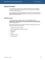
About this manual
This manual gets you started using the VIPER with RedBoot and Arcom Embedded
Linux (AEL). It lists the items you should find in your kit, and tells you how to unpack,
connect and configure the board.
This manual also covers the CYCLOPS product. The CYCLOPS is pre-installed with the
same Linux software as the AEL Development kit. All AEL-specific documentation also
applies to the CYCLOPS system.
Related documents
This Quickstart Manual is supplied as part of the VIPER RedBoot and AEL
Development Kit. Other manuals that you may need are provided on the CD-ROM that
accompanies your Development Kit. These include the VIPER Technical Manual and
the AEL Technical Manual.
Detailed information about AEL is provided in the AEL Technical Manual. This manual
includes information about the following:
© 2005 Arcom
•
Configuration files and boot scripts.
•
Making an application run automatically at boot.
•
AEL contents.
•
Installation.
•
Utilities.
•
Secure Shell (SSH).
•
Compiling a kernel.
Issue E
5
VIPER Embedded Linux Development Kit Quickstart
About this manual
Conventions
Symbols
The following symbols are used in this guide:
Symbol
Explanation
Note - information that requires your attention.
Tip - a handy hint that may provide a useful
alternative or save time.
Caution - proceeding with a course of action may
damage your equipment or result in loss of data.
Typographical conventions
This manual contains examples of commands that you can enter. These are shown as
follows:
$ make install DESTDIR=/tmp/target-install
The initial symbol ($ in this case) indicates the prompt that the command is for, and
should not be typed.
The prompts used are explained in the following table:
Prompt
Explanation
$
Linux (bash shell) as a regular user.
#
Linux (bash shell) as root.
RedBoot>
RedBoot command line.
Different fonts are used throughout the manual to identify different types of information,
as follows:
© 2005 Arcom
Font
Explanation
Italics
Parts of a command that should be substituted with
appropriate values.
Bold
Information that you enter yourself.
Screen text
Information that is displayed on screen.
Issue E
6
VIPER Embedded Linux Development Kit Quickstart
Getting started
Getting started
What’s in the kit?
The VIPER RedBoot and AEL Development Kits contain the VIPER Industrial Compact
Enclosure (ICE), which includes:
•
VIPER-400-M64-F32.
•
UPS power supply.
•
CompactFlash IEEE802.11b WiFi Card.
•
Flat panel display 5.5" NEC (optional).
•
Touchscreen and touchscreen controller (optional).
The CYCLOPS Development Kit contains the CYCLOPS Enclosure, which includes:
•
VIPER-400-M64-F32.
•
Flat panel display 8.4" NEC.
•
Touchscreen and touchscreen controller.
All Development Kits contain:
•
+24V @ 2.5A max (85-264 VAC input) power supply.
•
US, UK or EURO power supply cable.
•
Crossover RJ45 Ethernet cable.
•
Null modem cable.
•
This Quickstart Manual.
In addition, the AEL and CYCLOPS Development Kits include the following:
1
•
AEL support and installation CD.
•
Fedora Core installation media1.
•
AEL Technical Manual (on CD).
fedora.redhat.com
© 2005 Arcom
Issue E
7
VIPER Embedded Linux Development Kit Quickstart
Getting started
What else do I need?
An x86 Linux system compliant with version 1.3 of the Linux Standard Base2 is required
for the Arcom Embedded Linux host environment. Suitable systems include PCs with
Debian GNU/Linux, RedHat Linux, Fedora Core or SUSE Linux.
In addition, the following information may be useful:
•
Networking details for the VIPER. If your network does not have a DHCP server,
ask your network or system administrator for the following:
- IP address and subnet mask (netmask).
- Default gateway IP address (if required).
- Name server (DNS) IP address (optional).
•
2
Networking details for the host machine.
http://www.linuxbase.org/
© 2005 Arcom
Issue E
8
VIPER Embedded Linux Development Kit Quickstart
Getting started
What peripherals are supported?
Linux supports the following peripherals in this release:
• 5 UARTs, COM1 through COM5, including the processor’s internal FFUART,
BTUART and STUART.
• On-board Flash array.
• CompactFlash+.
• Ethernet interface.
• Audio.
• A variety of flat panels, including the supplied flat panel running at 320 x 240
(optional).
• Touchscreen.
• Power management.
• GPIO.
• Real time clock.
• SRAM.
• USB host controller.
• PC/104 bus. Drivers are available for a range of Arcom and third party PC/104
boards.
© 2005 Arcom
Issue E
9
VIPER Embedded Linux Development Kit Quickstart
Unpacking and connecting up
Unpacking and connecting up
This section guides you, step-by-step, through the process of connecting up the VIPER
for the first time and powering up the system. The VIPER is delivered ready to run.
There are no link settings or configuration switches that need to be adjusted for the
board to operate.
A number of the components are static-sensitive, so standard anti-static
precautions must be taken during use. For more information, see Anti-static
handling, page 4.
If you follow the procedure described below, the board powers up automatically and
loads the RedBoot boot loader from the on-board Flash array. If you have the AEL
Development Kit, it continues to load automatically and boots AEL.
To power up the VIPER and boot AEL, follow these steps:
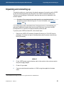
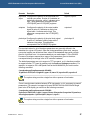
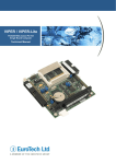
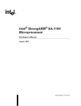
1
Remove the VIPER ICE (Industrial Compact Enclosure) or CYCLOPS from its
packaging. If it shows any signs of damage during transit, please contact Arcom
before proceeding.
VIPER ICE
3
2
Fit the VIPER power supply interface cable to the socket on the enclosure and to
the power supply adapter.
3
Fit the AC input cable.
4
Connect a serial terminal emulator3 to COM1 using the supplied null modem
cable.
Such as Minicom running on a Linux PC or Hyper Terminal on a Windows PC.
© 2005 Arcom
Issue E
10
VIPER Embedded Linux Development Kit Quickstart
5
Unpacking and connecting up
Configure the serial terminal as follows:
• 115200 baud.
• No parity.
• 8 data bits.
• No handshaking.
6
Switch on the VIPER board once the terminal emulator is set up on the host PC.
What happens next depends on whether you have a basic RedBoot Development
Kit, an AEL Development Kit or a CYCLOPS:
• If you have a RedBoot Development Kit, you are dropped to the RedBoot
command prompt, where you can upload and execute your application. For
more information see page 13 and the AEL Technical Manual, which is in the
/manuals/ folder on the Development Kit CD.
-or• If you have an AEL Development Kit or CYCLOPS, the Linux operating system
is loaded from the on-board Flash array, and the board displays a Linux
prompt.
For a description of AEL see page 15 and the AEL Technical Manual, which is
in the /manuals/ folder on the Development Kit CD.
© 2005 Arcom
Issue E
11
VIPER Embedded Linux Development Kit Quickstart
Power supply
Power supply
The AC Power Supply Unit (PSU) supplied in the kit is rated at 2.5A @ +24V DC. This is
designed to support the requirements of the VIPER ICE or CYCLOPS. If additional
devices are powered from this supply, ensure that the overall current rating is not
exceeded.
In a VIPER ICE system, the UPS signal /POWER_DOWN is connected to /OUT0 on pin
13 of PL9 of the VIPER. This means the UPS can be shut down using GPIO20.
© 2005 Arcom
Issue E
12
VIPER Embedded Linux Development Kit Quickstart
RedBoot
RedBoot
What is RedBoot?
RedBoot is a complete bootstrap environment for embedded systems. Based on the
eCos Hardware Abstraction Layer, RedBoot inherits the eCos qualities of reliability,
compactness, configurability, and portability.
RedBoot enables download and execution of embedded applications via serial or
Ethernet, including embedded Linux and eCos applications. It can be used for both
product development (debug support) and in deployed products in the field (Flash
update and network booting).
Ethernet download and debug support is included. This means RedBoot can retrieve its
IP parameters via BOOTP or DHCP, and program images can be downloaded using
TFTP or HTTP. Images can also be downloaded over serial (using X- or Y-modem) or
loaded from a JFFS2 file system on the on-board Flash.
An interactive command-line interface is accessible via serial or Ethernet and allows
management of Flash images, image download, RedBoot configuration, etc. For
unattended or automated startup, boot scripts can be stored in Flash. This allows, for
example, loading of images from Flash or a TFTP server.
You cannot use the command-line interface via Ethernet if you have an
automatic boot script enabled which launches an application or another
operating system, since RedBoot does not stop to listen for TCP/IP activity.
The Arcom Embedded Linux (AEL) Technical Manual contains details of many of the
RedBoot commands that are useful when using RedBoot as a boot loader for another
operating system (such as Linux) or to launch an application. Full RedBoot
documentation is available in the eCos Reference Manual, which is in the /manuals/
folder on the Development Kit CD.
Default boot script:
If you have purchased an AEL Development Kit, the default boot script on the VIPER is
configured to load a Linux kernel from the JFFS2 filesystem and execute it:
clock –l 27 –m 4 –n 10
mount −t jffs2 −f filesystem
load −r −b %{FREEMEMLO} %{kernel}
exec −c %{cmdline}
%{FREEMEMLO} is a predefined alias for the lowest address of available memory.
%{kernel} is an alias for the full path name of the Linux kernel to boot.
%{cmdline} is an alias for the kernel command line to use.
Refer to the AEL Technical Manual for further details.
© 2005 Arcom
Issue E
13
VIPER Embedded Linux Development Kit Quickstart
RedBoot
CPU Core Clock Frequency and the clock command
Versions of RedBoot on the VIPER up to and including V3I3 initialized the CPU clock to
200MHz at boot time. For version V3I4 this was changed to boot at 400MHz. The
current version (V3I5) no longer changes the clock rate, so it remains at the default
100MHz setting. However, this version introduces an additional command (clock),
which can be used to set the clock to any of the frequencies described in the CPU clock
frequency scaling section on page 22. The clock command takes parameters for the L,
M and N settings which control the clock speed as described in that section. The value
of N should be 10 times the actual value. Therefore, to set N to 1.5, pass the option
–n 15. For example:
•
To set the clock frequency to 300MHz power saving mode:
RedBoot> clock –l 27 –m 1 –n 30
•
To set the clock frequency to 200MHz performance mode:
RedBoot> clock –l 27 –m 2 –n 10
If you have an AEL Development Kit, the default AEL boot script initializes the clock to
400MHz.
© 2005 Arcom
Issue E
14
VIPER Embedded Linux Development Kit Quickstart
Arcom Embedded Linux (AEL)
Arcom Embedded Linux (AEL)
What’s in AEL?
AEL is a space-optimized Linux distribution based on Linux kernel version 2.6.
AEL includes many of the standard file, shell and text utilities. As well as the basic
Linux system, the default installation includes:
•
OpenSSH Secure Shell.
•
Minimal X Window System.
•
Web server.
For a complete list of software and an explanation of how to add and remove packages
please consult the AEL Technical Manual, which is on the accompanying CD.
© 2005 Arcom
Issue E
15
VIPER Embedded Linux Development Kit Quickstart
Arcom Embedded Linux (AEL)
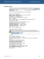
Booting the system
Once the system has been connected and powered up (as described in Unpacking and
connecting up, page 10) the board automatically boots to a Linux prompt, as follows:
Uncompressing Linux................. done, booting the kernel.
...
CPU: XScale−PXA255 [69052d06] revision 6 (ARMv5TE)
...
Machine: Arcom VIPER SBC
Memory policy: ECC disabled, Data cache writeback
Memory clock: 99.53MHz (*27)
Run Mode clock: 398.13MHz (*4)
Turbo Mode clock: 398.13MHz (*1.0, active)
Built 1 zonelists
Kernel command line: root=/dev/mtdblock2 rootfstype=jffs2 ro
console=ttyS0,115200
...
3 RedBoot partitions found on MTD device flash
Creating 3 MTD partitions on "flash":
0x00000000−0x0001f000 : "FIS directory"
0x0001f000−0x00020000 : "RedBoot config"
0x00020000−0x02000000 : "filesystem"
...
INIT: version 2.85 booting
...
Configuring network interfaces...
If you do not have a DHCP server and you have not configured a static IP
address, the board pauses at this point while it searches for a DHCP server. See
Setting up networking, page 18.
... done.
...
INIT: Entering runlevel: 3
Starting system log daemon: syslogd.
Starting hotplug subsystem:.... already started. process pending
events.
Starting kernel log daemon: klogd.
Starting NFS common utilities: statd.
Loading /etc/console/keymap.gz
Starting PCMCIA services: done.
Starting internet superserver: inetd.
Starting http server: thttpd.
Starting OpenBSD Secure Shell Server: sshd.
Starting periodic command scheduler: cron.
Arcom Embedded Linux (ttyS0)
viper login:
© 2005 Arcom
Issue E
16
VIPER Embedded Linux Development Kit Quickstart
Arcom Embedded Linux (AEL)
Logging in
You may login to the VIPER as root (the superuser or administrator) using the following
details:
Login name:
root
Default password: arcom
© 2005 Arcom
Issue E
17
VIPER Embedded Linux Development Kit Quickstart
Arcom Embedded Linux (AEL)
Setting up networking
As supplied, the board uses the DHCP protocol to configure the network. This requires
a DHCP server to be available on your network. For more information, please consult
your network administrator.
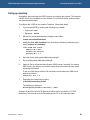
To configure the VIPER to use a static IP address, follow these steps:
1
Log in to the VIPER by entering the following log in details:
• Login name: root
• Password: arcom
2
Edit the file /etc/network/interfaces using the nano editor:
# nano /etc/network/interfaces
3
Modify the iface eth0 inet dhcp line to look like the following (substituting your
own IP address and netmask):
iface eth0 inet static
address 10.7.28.2
netmask 255.255.0.0
gateway 10.7.1.1
4
Save the file by holding down Ctrl and pressing O.
5
Exit by holding down Ctrl and pressing X.
6
Optional. Set up a Domain Name System (DNS) server if required. You need a
DNS server if you want to use domain names (such as www.arcom.com) when
accessing the Internet.
To set up a DNS server, edit the file /etc/resolv.conf and add your DNS server
address as follows:
nameserver 10.7.1.9
7
Reinitialize the networking by typing:
# /etc/init.d/networking restart
The following is displayed:
Reconfiguring network interfaces...done
Chapters 25 and 26 of the RUTE Manual provide a useful introduction to TCP/IP
networking. This manual is on the Development Kit CD, in the /manuals/ folder.
© 2005 Arcom
Issue E
18
VIPER Embedded Linux Development Kit Quickstart
Arcom Embedded Linux (AEL)
The file system
The file system used on the VIPER Flash memory is a compressed Journaling Flash
File System (JFFS2). JFFS2 has the following advantages:
•
Robustness.
•
Power fail safe.
•
No integrity scan (fsck) is required at boot time.
•
Flash wear levelling.
•
Transparent compression, with a typical compression ratio of 2:1.
The on-board Flash is partitioned using RedBoot FIS, as shown in the following table:
Partition #
Block device
Size (KB)
Offset (KB)
Description
0
/dev/mtdblock0
124
0
Partition table
1
/dev/mtdblock1
4
124
RedBoot configuration
2
/dev/mtdblock2
remainder
128
Root file system
Previous versions of Arcom Embedded Linux on the VIPER made use of a
separate kernel partition. From version 4 issue 1 onwards, the kernel is stored
as a regular file in the /boot/ folder on the root filesystem.
In addition, a 4MB RAM-based file system is mounted on /var/tmp for temporary files.
These are lost on reboot.
The basic AEL install uses about 7.9MB of physical Flash. On a board with 32MB of
Flash memory fitted, this leaves about 24.1MB free. This is about 50MB of free space,
assuming a typical 2:1 compression ratio. You can make additional space available by
removing unused packages. For more information, refer to the AEL Technical Manual,
which is in the /manuals/ folder on the Development Kit CD.
The default Flash image is on the Development Kit CD, in the /images/ folder. For an
explanation of how to reload a complete Flash image, see the AEL Technical Manual.
© 2005 Arcom
Issue E
19
VIPER Embedded Linux Development Kit Quickstart
Arcom Embedded Linux (AEL)
Linux kernel
The version of the Linux kernel used on the VIPER is a standard Linux 2.6 kernel tree
with patches to provide support for Arcom’s boards.
Source and configuration
The kernel sources are installed in the host environment as /opt/arcom/src/linux-sourceVERSION.tar.gz.
Once you have unpacked the kernel source you can configure the default VIPER kernel
with:
$ make ARCH=arm viper_defconfig
The kernel may now be built and installed as described in the AEL Technical Manual.
Default command line
The default kernel command line is:
root=/dev/mtdblock2 rootfstype=jffs2 ro console=ttyS0,115200
© 2005 Arcom
Issue E
20
VIPER Embedded Linux Development Kit Quickstart
Arcom Embedded Linux (AEL)
Hardware configuration
Touchscreen Controller (TSC1)
If your VIPER ICE was supplied with a touchscreen, the touchscreen controller is
attached to /dev/ttyS2 (COM3). In a CYCLOPS system, the touchscreen controller is
attached to /dev/ttyS4 (COM5).
PC/104 bus
The PC/104 bus on the VIPER is attached via the second PCMCIA controller built in to
the PXA255 processor.
The PC/104 I/O address space is mapped at virtual address 0xF1000000. This means
that a PC/104 card that has been configured at I/O address 0xXXX is available at virtual
address 0xF1000XXX. This virtual address is the correct value to use when configuring
a device driver for that card, rather than the associated physical address.
Previous versions of Arcom Embedded Linux on the VIPER using version 2.4 of
the Linux kernel used 0xF7000000 as the offset for the PC/104 I/O address
space.
The PC/104 memory address space is available at physical address 0x3C000000. This
means that a PC/104 card that has been configured for memory address 0xXXXX is
available at physical address 0x3C00XXXX. It is the responsibility of the driver to map
this address into the kernel’s virtual address space before use.
The PC/104 interrupts are mapped as shown in the following table:
PC/104 interrupt
VIPER interrupt
3
104
4
105
5
106
6
107
7
108
10
109
11
110
12
111
9*
112
14*
113
15*
114
* These interrupts are only available on version 2 of the VIPER hardware.
For more information, see the VIPER Technical Manual and PXA255 Developer’s
Manual.
© 2005 Arcom
Issue E
21
VIPER Embedded Linux Development Kit Quickstart
Arcom Embedded Linux (AEL)
CPU clock frequency scaling
The PXA255 processor used on the VIPER can scale the core clock frequency from
100 to 400MHz, allowing an application to dynamically trade off performance against
power consumption. The functionality is exposed in Linux via special files in the /sys
system. These can be manipulated directly (e.g. using cat and echo), but are better
controlled using the cpufreq-info and cpufreq-set utilities. Both utilities are described
below.
The processor’s clock and power manager, including the available Core Clock Control
Register (CCCR) multiplier configurations, are described in detail in the PXA255
Processor Developer’s Manual, which is in the /references/ folder on the Development
Kit CD. The CCCR consists of 3 multipliers - L, M and N:
•
The L multiplier converts the basic 3.6864MHz crystal frequency into the memory
clock frequency. Typical values of L are 27, 36, and 45.
•
The M multiplier converts the memory clock frequency into the run-mode frequency.
Typical values of M are 1, 2 and 4.
•
The N multiplier converts the run-mode frequency into the turbo-mode frequency.
Typical values of N are 1.0, 1.5, 2.0 and 3.0.
Not all combinations of L, M and N are valid. Some valid combinations are
described below, and more information is available in the PXA255 Processor
Developer’s Manual.
The Linux kernel divides the available clock configurations into two complementary sets
of available frequencies, corresponding to the run-mode and turbo-mode multipliers.
The first set is the ‘performance’ set. These use the run-mode multiplier (CCCR[M]) to
scale the clock frequency. Increasing the run-mode multiplier in this way gives the best
performance but at the cost of increased power consumption.
The second set of frequencies are the ‘powersave’ frequencies. These use the turbomode multiplier (CCCR[N]) to scale the clock frequency. This uses less power than the
run-mode multiplier but with a performance cost (especially if frequent memory
accesses are required), since the core must wait for these while running in turbo mode.
The Linux kernel manages the current clock configuration using a software governor
combined with user-specified minimum and maximum desired clock frequencies.
In the default VIPER kernel three governors are provided:
© 2005 Arcom
•
The ‘performance’ governor selects the maximum allowed frequency from the
processor’s available performance frequencies.
•
The ‘powersave’ governor selects the lowest available frequency from the available
powersave frequencies.
•
The ‘userspace’ governor allows direct userspace selection of a frequency from the
available performance frequencies.
Issue E
22
VIPER Embedded Linux Development Kit Quickstart
Arcom Embedded Linux (AEL)
The default is to use the performance governor with a maximum frequency of 400MHz.
The powersave and userspace governors are supplied as loadable kernel modules,
called cpufreq_powersave and cpufreq_userspace respectively. They may be loaded
using the modprobe command.
The available performance clock rates are listed in the following table. They correspond
to the modes available when the turbo mode multiplier, CCCR[N] is 1.0.
Clock speed
(KHz)
Core Clock
Configuration
Register
(L, M and N
multipliers)
Memory clock
(MHz)
Run clock
(MHz)
Turbo clock
(MHz)
PX bus (MHz)
99532
27, 1, 1.0
99
99
99
50
132710
36, 1, 1.0
133
133
133
66
199065
27, 2, 1.0
99
199
199
99
265421*
36, 2, 1.0
133
265
265
133
331776*
45, 2, 1.0
166
332
332
166
398131*
27, 4, 1.0
99
398
398
196
* Not available on 200MHz VIPER-LITE.
The available powersave clock rates are listed in the following table:
Clock speed
(KHz)
Core Clock
Configuration
Register
(L, M and N
multipliers)
Memory clock
(MHz)
Run clock
(MHz)
Turbo clock
(MHz)
PX bus (MHz)
99532
27, 1, 1.00
99
99
99
50
199065
27, 1, 2.00
99
99
199
50
298598*
27, 1, 3.00
99
99
299
50
398131*
27, 2, 2.00
99
199
398
99
* Not available on 200MHz VIPER-LITE.
© 2005 Arcom
Issue E
23
VIPER Embedded Linux Development Kit Quickstart
Arcom Embedded Linux (AEL)
The cpufreq-set utility can be used to select a governor and to set the minimum and
maximum allowable frequency. This is illustrated by the following examples:
• To select the performance governor and limit the maximum allowed speed to
200MHz:
# cpufreq-set --governor performance --max 199065
•
To select the powersave governor and set the minimum allowed frequency to
300MHz:
# modprobe cpufreq_powersave
# cpufreq-set –governor powersave --min 298598
•
To use the userspace governor and set a frequency of 400MHz:
# modprobe cpufreq_userspace
# cpufreq-set --governor userspace --freq 398131
Changing the clock frequency automatically regulates the core voltage in order
to maximize power savings.
The current settings can be examined using the cpufreq-info utility:
# cpufreq-info
...
analyzing CPU 0:
...
hardware limits: 99.5 MHz − 398 MHz
available cpufreq governors: performance
current policy: frequency should be within 398 MHz and 398 MHz.
The governor "performance" may decide which speed to
use within this range.
current CPU frequency is 398 MHz (asserted by call to hardware).
Sleep and wake up support
The PXA255 processor supports a low power sleep mode in which the processor shuts
down entirely until some external or internal stimulus causes it to wake up. This
stimulus can be either an alarm generated by the processor’s internal Real Time Clock
(RTC) or a change in the state of one of the processor’s GPIO lines. For an explanation
of how to configure the wake up source and ensure that power consumption is reduced
to the minimum, see the VIPER Technical Manual.
Once a wake up source has been configured, the processor can be put into sleep mode
by writing to the special file /sys/power/state.
The following command, for example, would not appear to return until after the
processor has been woken up:
# echo –n “mem” > /sys/power/state
© 2005 Arcom
Issue E
24
VIPER Embedded Linux Development Kit Quickstart
Arcom Embedded Linux (AEL)
If you intend to use the PXA255’s internal RTC as a wake up source, you must unload
the driver for the external RTC (which cannot perform the wake up function) and load
the driver for the internal RTC, as follows:
1
Remove the external DS1307 RTC driver:
# rmmod ds1307
2
Install the SA1100/PXA255 RTC driver:
# modprobe sa1100-rtc
3
Resynchronize the SA1100/PXA255 RTC to the correct time from the system
clock:
# hwclock –systohc
The source for the arcom-utils package (which is on the Development Kit CD, in the
/packages/arcom-utils folder) contains the script viper-sleep.sh, which is an example of
how to put a VIPER board to sleep and wake it up again.
LCD controller
The LCD controller driver module (pxafb) is configured by default for the 320x240 TFT
display (part number NL3224BC35), which is an optional part of the VIPER ICE box.
The CYCLOPS image is configured to support the CYCLOPS flat panel (see page 29).
The driver module can be loaded using the normal modprobe command:
# modprobe pxafb
In order to use other LCD modules, extra parameters must be passed to the modprobe
command, either on the command line or using one of the methods described in the
AEL Technical Manual. The options are given as a comma separated list of parameters.
Where a parameter requires a value, it is separated from the parameter name using a
colon. The available parameters are listed in the following table. The registers referred
to are described in section 7.6.4 of the PXA255 Processor Developer’s Manual, which
is in the /references/ folder on the Development Kit CD.
Parameter
Description
Default
mode
The required video mode written as:
mode:320x240-16
XRESxYRES-BPP
Where XRES is the X axis resolution, YRES is
the Y axis resolution and BPP is the desired bit
depth.
The hardware supports bit depths of 1, 2, 4, 8 and
16-bits. The LCD driver is known to work well in 8or 16-bit mode.
This parameter corresponds to the LCCR1[PPL],
LCCR2[LPP] and LCCR3[BPP] registers.
Continued…
© 2005 Arcom
Issue E
25
VIPER Embedded Linux Development Kit Quickstart
Arcom Embedded Linux (AEL)
Parameter
Description
Default
pixclock
The pixel clock, expressed in picoseconds
(10-12s). This value is used in conjunction with
the current memory clock rate to calculate
LCCR3[PCD].
pixclock:157500
left, right,
hsynclen,
upper,
lower and
vsynclen
The timing parameters. All parameters are
given as a number of pixel clock ticks. The
upper and lower margins should be 0 for
passive (STN) displays.
left:7,
The values correspond to LCCR as follows:
upper:1,
•
left corresponds to LCCR1[BLW] + 1.
lower:1,
•
right corresponds to LCCR1[ELW] + 1.
vsynclen:20.
•
hsynclen corresponds to LCCR1[HSW] + 1.
•
upper corresponds to LCCR2[BFW].
•
lower corresponds to LCCR2[EFR].
•
vsynclen corresponds to LCCR2[VSW] + 1.
right:13,
hsynclen:63,
Several of these values are modified by + 1
because the hardware expects the desired value
– 1 to be programmed. The values given to this
parameter therefore correspond to the desired value
rather than the value programmed into the
hardware.
color or
mono
Configures the LCD controller for color or
monochrome panels. These parameters
correspond to the LCCR0[CMS] register.
color
active or
passive
Configures the LCD controller for active (TFT)
or passive (STN) displays. These parameters
correspond to the LCCR0[PAS] register.
active
single or
dual
In passive mode configures the LCD controller
for either single or dual panel displays. These
parameters correspond to the LCCR0[SDS]
register.
N/A
4pix or
8pix
In monochrome passive mode configures the
LCD controller for either 4 or 8 pixel mode.
These parameters correspond to the
LCCR0[DPD] register.
N/A
Continued…
© 2005 Arcom
Issue E
26
VIPER Embedded Linux Development Kit Quickstart
Parameter
Arcom Embedded Linux (AEL)
Description
Default
hsync and Configures the polarity of the horizontal and
vsync
vertical sync pulses. A value of 0 indicates an
active low sync pulse, while 1 indicates active
high. These parameters correspond to the
LCCR3[HSP] and LCCR3[VSP] registers.
hsync:0,vsync:0
outputen
outputen:1
Configures the polarity of the output enable
signal. A value of 0 indicates an active low
signal while 1 indicates active high. This
parameter corresponds to the LCCR3[OEP]
register.
pixclockpol Configures the polarity of the pixel clock signal.
A value of 0 indicates a falling edge while 1
indicates rising edge. This parameter
corresponds to the LCCR3[PCP] register.
pixclockpol:0
The required values for all of the above parameters are generally defined in the
datasheet for a given LCD panel. Often the timing parameters (pixel clock, margins,
sync pulse lengths) can be derived from values in the datasheet along with a certain
amount of trial and error. It is recommended that you read chapter 7 of the PXA255
Processor Developers manual since many of the parameters given to the driver
correspond directly to settings in the LCD controller hardware.
The default parameters are set to support a TFT type panel, so it is therefore possible
to support another TFT panel by passing only the mode and timings parameters. For
example, to support a 640 x 480 panel such as the NL6448AC20 you would use the
following command:
# modprobe pxafb options=mode:640x48016,pixclock:39722,left:16,right:81,upper:12,lower:31,hsynclen:63,vsynclen:2
The options string must be a single line with no spaces or line-breaks.
There is much greater variation between STN type panels, so it is necessary to pass all
parameters. For example, to support a Kyocera KCS057QV1AA-G00 320x240 single
panel color STN display you would use the following command:
# modprobe pxafb options=mode:320x2408,pixclock:154000,left:1,right:1,upper:0,lower:0,hsynclen:8,vsynclen:32,passive,c
olor,single,outputen:1,pixclockpol:0,hsync:1,vsync:1
The options string must be a single line with no spaces or line-breaks.
© 2005 Arcom
Issue E
27
VIPER Embedded Linux Development Kit Quickstart
Arcom Embedded Linux (AEL)
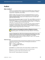
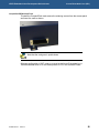
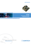
CompactFlash IEEE802.11b WiFi Card
To install the CompactFlash card remove the retaining screws from the access panel
and insert the card as shown:
Note that the card goes in upside down.
Software configuration of WiFi cards is covered in the Arcom Embedded Linux
Technical Manual which is on the development kit CD in the /manuals/ folder.
© 2005 Arcom
Issue E
28
VIPER Embedded Linux Development Kit Quickstart
Software configuration
Software configuration
The CYCLOPS and VIPER-LITE systems require some additional configuration. For
example you must specify flat panel driver parameters to support the panel supplied
with the CYCLOPS. If using the VIPER-LITE, you must inform the Linux kernel of the
reduced CPU speed.
The configuration required for each of these systems is described in the following
sections.
CYCLOPS software configuration
The CYCLOPS system is shipped with an AEL image that has been configured for the
CYCLOPS hardware. The image is available in the /images/ folder on the Development
Kit CD.
If you reinstall this image, you will need to recalibrate the touchscreen using the
following command:
# killall tsc1d
# tsc1cal --device /dev/ttyS4 --generate /etc/tsc1d.conf --ten-bit
The touchscreen controller software is described more fully in the AEL technical
manual.
The CYCLOPS image also contains a configuration file /etc/modprobe.d/cyclops, which
sets up the correct parameters for the flat panel driver and a script /etc/init.d/cyclops
which configures COM5 correctly for use with the touchscreen controller. These files
are provided by the package variant-cyclops.
VIPER-LITE software configuration
The VIPER-LITE is a reduced power VIPER derivative based around the 200MHz
PXA255 processor.
As it is based on the 200MHz part, it is necessary to inform the Linux kernel of the
reduced maximum CPU speed. This can be done by adding the following to the default
kernel command line:
"cpu_pxa.max_frequency=199065"
For more information, see Default command line on page 20.
This will limit the available CPU frequencies to 200MHz. For a discussion of CPU clock
frequency scaling, see page 22.
The VIPER-LITE Flash image available in the /images/ folder on the
Development Kit CD already contains the modified kernel command line.
© 2005 Arcom
Issue E
29
VIPER Embedded Linux Development Kit Quickstart
Support software
Support software
Target support software
When building applications for the VIPER board, you must use the AEL host
environment. This consists of a set of utilities that provide a cross-compile environment
targeting the VIPER board. A cross-compile environment is required in order to produce
binaries for the XScale processor.
For an explanation of how to install the host environment, refer to the AEL Technical
Manual, on the accompanying CD. This CD also includes example source code for
utilizing the Arcom-specific device drivers and utility programs.
Intel Integrated Performance Primitives (IPPs)
Intel supplies a set of code modules optimized for the XScale processor. These provide
basic functionality, including:
• Signal, image, speech and audio processing.
• Vector manipulation.
• Matrix math.
Further modules providing primitives useful in specific application areas are available.
These application areas include:
• Audio, video and speech codecs, for example MP3 (MPEG-1 Audio Layer 3), MPEG4, H263, JPEG, GSM-AMR and G723.1.
• Cryptography, for example DES, Triple DES, SHA1 and RSA.
For more information about Intel IPPs, see
developer.intel.com/design/pca/application4sprocessors/swsup/IPPv30.htm.
© 2005 Arcom
Issue E
30
VIPER Embedded Linux Development Kit Quickstart
Real-time Linux on the VIPER
Real-time Linux on the VIPER
Linux was not designed with hard real-time capabilities in mind. It usually meets the
needs of soft real-time applications. However, under certain circumstances the
scheduling and other latencies do not meet the needs of hard real-time control and
communication applications.
For this reason, Finite State Machine Laboratories (FSMLabs, Inc) developed
RTLinuxPro. This is a tested and validated, hard real-time, POSIX operating system
that runs Embedded Linux as an application platform. Within RTLinuxPro, the standard
Linux kernel runs as a low priority task on top of a hard real-time RTOS, RTCore. This
means that RTLinuxPro can meet hard real-time deadlines, while offering the power of
Linux for less performance-critical aspects of applications.
The VIPER Development Kit CD contains an RTLinuxPro demonstration binary for
evaluation purposes. The demonstration consists of an RTLinuxPro-enabled kernel
from FSMLabs, and a RAM disk image containing a simple application to measure the
interrupt and scheduling latency (jitter).
The jitter test measures the total time delta from the point when the interrupt is
generated to the point when the interruption actually happens (i.e. the interrupt latency).
It also measures scheduler entry to decide who needs to run, and includes a context
switch to get the required task in and running so it can sample the clock.
Obtaining RTLinuxPro
The VIPER Development Kit includes an evaluation version of RTLinuxPro for the
PXA255-based VIPER. This is for demonstration purposes only, and cannot be used or
shipped in an end product. The Development Kit CD does not contain RTLinuxPro
development tools or licensed products.
If you want to develop real-time applications using RTLinuxPro, contact FSMLabs
directly at [email protected].
Source for the parts of the RTLinux demonstration that are licensed under the GPL is
available on request under section 3(b) of the GPL.
© 2005 Arcom
Issue E
31
VIPER Embedded Linux Development Kit Quickstart
Real-time Linux on the VIPER
Performance
To indicate the level of performance achieved using RTLinuxPro, Arcom prepared a test
application to exercise the Ethernet port with a ping flood and repeatedly write two large
files to the JFFS2 flash drive. Essentially, this represents a ‘busy’ foreground task
running under Linux. The jitter test was run with Arcom’s standard Linux and then
repeated using RTLinuxPro. The test was performed on a standard VIPER board
running with a 400MHz CPU clock speed.
The worst-case jitter measurements running on a 400MHz PXA255 VIPER are shown
in the following table:
Linux variant
Maximum jitter
AEL
231ms
FSMLabs RTLinuxPro
50.8µs
Evaluating RTLinuxPro
The VIPER is not installed with RTLinuxPro as standard. The RTLinuxPro kernel and
RAM-based file system images are provided on the Development Kit CD in the folder
/images/rtlinux-demo. They can be booted using the following procedure. Doing so
does not affect the standard AEL image, which is stored in the Flash drive. To run the
test you must boot RTLinuxPro and then load the test application. To do this, follow
these steps:
1
Drop to the RedBoot command prompt. You do this by holding down Ctrl and
pressing C during the early stages of boot.
2
Enter the following commands:
RedBoot> load -r -b 0x800000 initrd.gz
RedBoot> load -r -b 0x400000 zImage.viper
RedBoot> exec -r 0x800000 -s 0x1000000 -c "console=ttyS0,115200
root=/dev/ram0"
The RTLinuxPro system boots and drops to a shell log in.
3
© 2005 Arcom
Issue E
Mount the flash and copy multiple files repeatedly in and out of the file system:
# mount /dev/mtdblock3 /mnt
# while :; do cp /lib/libc-2.2.5.so /mnt/tmp/x; rm /mnt/tmp/x; done &
[1] 1722
# while :; do cp /lib/libc-2.2.5.so /mnt/tmp/y; rm /mnt/tmp/y; done &
[2] 1723
32
VIPER Embedded Linux Development Kit Quickstart
4
Real-time Linux on the VIPER
Set the CPU speed to either 200MHz or 400MHz as follows:
• To set it to 200MHz enter:
# echo 200000 > /proc/sys/cpu/0/speed
• To set it to 400MHz enter:
# echo 400000 > /proc/sys/cpu/0/speed
5
Do one of the following:
• For the Linux test, run:
# /bin/jitter.user
• For RTLinuxPro, you must start the underlying RTOS first. Run the following
commands by entering:
# /bin/rtcore &
Allow a short delay for the RTOS to load and configure itself, then enter:
# /bin/jitter.rtl
6
Run a ping flood of the board from another machine:
# ping -f viper.ip
Worst-case figures are displayed for each test. These are all that matter in hard
real-time systems.
Arcom provides support for RTLinuxPro through FSMLabs directly. Contact
FSMLabs (at [email protected]) if you have questions, or if you require
more information about the capabilities of and development tools for
RTLinuxPro.
© 2005 Arcom
Issue E
33
VIPER Embedded Linux Development Kit Quickstart
Appendix - Contacting Arcom
Appendix - Contacting Arcom
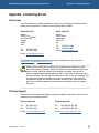
Arcom sales
Arcom’s sales team is always available to assist you in choosing the board that best
meets your requirements. Contact your local sales office or hotline.
Sales office US
Sales office UK
Arcom
7500W 161st Street
Overland Park
Kansas
66085
USA
Arcom
Clifton Road
Cambridge
CB1 7EA
UK
Tel:
913 549 1000
Fax: 913 549 1002
E-mail: [email protected]
Tel:
01223 411 200
Fax: 01223 410 457
E-mail: [email protected]
Comprehensive information about our products is available from our web sites:
www.arcom.com and www.arcom.co.uk.
While Arcom’s sales team can assist you in making your decision, the final
choice of boards or systems is solely and wholly the responsibility of the buyer.
Arcom’s entire liability in respect of the boards or systems is as set out in
Arcom’s standard terms and conditions of sale. If you intend to write your own
low level software, you can start with the source code on the disk supplied. This
is example code only to illustrate use on Arcom’s products. It has not been
commercially tested. No warranty is made in respect of this code and Arcom
shall incur no liability whatsoever or howsoever arising from any use made of
the code.
Technical support
Arcom has a team of technical support engineers available to provide a quick and free
response to your technical queries.
Technical support US
Technical support UK
Tel:
913 549 1010
Tel:
+44 (0)1223 412 428
Fax:
913 549 1001
Fax:
+44 (0)1223 403 409
E-mail: [email protected]
© 2005 Arcom
Issue E
E-mail: [email protected]
34
VIPER Embedded Linux Development Kit Quickstart
Index
Index
A
G
applications, embedded · 13
gateway · 8
getting started · 7
GPIO · 9, 12
B
battery · 4
board features · 4
boot
strap · 13
booting · 16
C
cable, AC input · 10
installation · 7
command line · 20
contact details · 34
conventions · 6
copyright · 2
CYCLOPS · 7, 29
D
H
handling · 4
host
environment · 30
system · 8
I
industrial compact enclosure · 10
integrated performance primitives · 30
Intel · 30
interface · 13
IP address · 8
static · 18
IPP · See integrated performance primitives
J
DHCP · 18
server · 16
DNS · 8, 18
download · 13
JFFS2 · 19
jitter · 31, 32
journaling · 19
E
K
embedded applications · 13
ethernet · 9, 13
kernel · 20
command line · 20
configuration · 20
sources · 20
F
file
system · 19
temporary · 19
Flash array · 9
flat panel · 9
L
Linux · 11, 15, 20
real-time · 31
N
networking · 18
details · 8
© 2005 Arcom
Issue E
35
VIPER Embedded Linux Development Kit Quickstart
P
packaging · 4
PC/104 · 9, 21
performance · 32
peripherals · 9
power supply · 10
primitives · 30
prompts · 6
R
real-time Linux · 31
RedBoot · 11, 13
requirements · 8
RTLinuxPro · 31
evaluating · 32
STUART · 9
support
software · 30
technical · 34
symbols · 6
T
technical
manual · 13
support · 34
temporary files · 19
touchscreen · 21
trademarks · 2
U
UART · 9
unpacking · 10
S
secure shell · 15
serial terminal
configuring · 11
emulator · 10
server
DHCP · 16
FTP · 15
web · 15
sleep · 24
source code · 34
SRAM · 9
static · 4
IP address · 18
© 2005 Arcom
Index
Issue E
V
VIPER-LITE · 29
W
wake up · 24
warranty · 2
X
X window · 15
XScale · 30
36