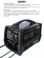
1
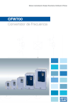
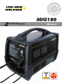
(Power Source) IM I S S 85 ER WELDE R SUPPORT L MIG180 D Welding G 2 YEARS Warranty td 1985 UNI-FLAME N U G AUSTR IN E SINC IAN AL 19 us Of A tralia P t yL UNI-FLAME AUTOLIFT s un G WE Manual Lift Arc DC/TIG 240 Volt Standard MIG / MAG SAFETY 1. SAFETY Welding and cutting equipment can be dangerous to both the operator andispeople in or nearand the may c Welding dangerous, surrounding working area, if the equipment is not correctly operated. only be please r whenEquipment welding. must For details, used under the strict and comprehensive observance of all relevant safety regulations. Please accident prevention requirements o read and understand this instruction manual carefully before the installation and use/operation of this equipment. • Do not switch the function modes while the machine is operating. Switching of the function modes during welding can damage the machine. Damage caused in this manner will not be covered under warranty. A safety switch is necessary to prevent the equipment from electric leakage. Welding tools and accessories should be of high quality and in good working order. Operators should be trained and or qualified. Electric shock: It can kill. Connect the primary input cable according to Australian standard regulation. Avoid all contact with live electrical parts of the welding circuit, electrodes and wires with bare hands. The operator must wear dry welding gloves while he/she performs the UNI-PLAS welding task. The operator should keep the work piece insulated from himself/herself. Smoke and gas generated whilst welding or cutting can be harmful to people’s health. Avoid breathing the smoke and gas generated whilst welding or cutting. Keep the working area well ventilated. Arc rays are harmful to people’s eyes and skin. Always wear a welding helmet and suitable protective clothing including welding gloves whilst the welding operation is performed. Measures should be taken to protect people in or near the surrounding working area, from all hazards associated with welding. • • • • • • • • • Fire hazard • • The welding sparks may cause fire, therefore remove flammable material away from the working area. Have a fire extinguisher nearby, and have a trained person ready to use it. Noise: possibly harmful to people’s hearing. Noise is generated while welding/cutting, wear approved hearing protection when noise levels are high. Machine fault: Consult this instruction manual. Contact your local dealer or supplier for further advice. • • • *** CAUTION *** Do not heat, cut or weld tanks, drums or containers until the proper steps have been taken to insure that such procedures will not cause flammable or toxic vapors from substance inside. These can cause an explosion even though the vessel has been “cleaned”.Vent hollow castings or containers before heating, cutting or welding. They may explode. 2. GENERAL DE Advanced IGBT in Inverter freque welder. Great reduction energy saving e Switching freq pollution. Leading control m Advanced SCM INTRODUCTION Thank you for purchasing this UNI-MIG Welder. Before operating the machine, it is essential that you read this manual thoroughly and carefully follow all instructions given. GUARANTEE This UNIMIG product is guaranteed against faulty manufacture for a period of 2 Years from the date of purchase. Please keep your receipt as proof of purchase. This guarantee is invalid if the product is found to have been abused or tampered with in any way, or not used for the purpose for which it was intended. Faulty goods should be returned to their place of purchase, no product can be returned to us without prior permission. This guarantee does not effect your statutory rights. ENVIRONMENTAL PROTECTION UNI-PLAS Do not dispose of this product with general household waste. All tools, accessories and packaging should be sorted, taken to a re-cycling centre and disposed of according to the laws governing Waste Electrical and Electronic Equipment. MOUNTING THE WELDING WIRE SPOOL WARNING: Ensure that the welder is not connected to the mains supply. 1. Open the side panel, by pushing the latch down and allowing the side panel to drop down. 2. Remove the locking knob and retaining disc. 3. Place the spool of welding wire over the spindle so that it sits against the spring. · Do not release the tension on the wire as it will unravel causing feeding problems later. · The wire will feed off the spool anticlockwise from the bottom of the reel. · The spool must be fitted with the correct orientation otherwise it will not feed correctly. UNI-PLAS SETTING THE DRIVE ROLLER SIZE 1. Loosen the tensioning knob and pivot it towards you 2. Lift up the arm. 3. Take hold of the triangular knob on the drive roller cover and rotate it 90° anticlockwise to release it. 4. Pull the roller retainer off the drive spindle to reveal the roller. 5. Pull the roller off the drive spindle. · The groove size is stamped on the corresponding side of the roller. Select the groove size according to the size of the wire you are using and put the roller back on the spindle with your chosen side facing you. 6. Replace the drive roller cover back onto the drive spindle with the opening facing right. 7. Ensure that the flanges at the base of the drive roller cover, seat fully into the circular recess in the main moulding and then rotate the drive roller cover through 90° to lock it in place. 8. There are different drive rollers for aluminium and flux cored wires THREADING THE WIRE IMPORTANT: Do not release the tension on the wire as it will unravel causing feeding problems later. 1. Pull out the end of the wire from the spool, taking care not to release the tension. · We recommend you cut off and discard the first 10 cm of wire from the spool to avoid burrs and then straighten the next 15 cm of wire to help with feeding. 2. Loosen the tensioning knob and pivot it towards you. 3. Lift up the arm. 4. Pass the wire through the guide, over the drive roller and into the torch liner. · Push about 10-15 cm into the torch liner. 5. Lower the arm and replace the tensioning knob. · Tighten the tensioning knob sufficiently to hold firmly, but do not fully tighten. NOTE: Correct tension will allow the wire to feed into the torch liner smoothly, but will allow the drive roller to slip in the event of a blockage. 6. Close the side panel of the welder. 7. Pull off the torch shroud with a twisting movement, then unscrew the contact tip. 8. Connect the welder to the power supply and switch ON. 9. Set the ‘WIRE FEED’ rotary control on the front panel to position 7 or 8 and squeeze UNI-PLAS the trigger on the torch body. · The wire will feed through the MIG Torch until it appears at the torch tip. · Ensuring the hose is free from kinks during this process will assist the wire in its passage through the hose liner. 10. Release the trigger and switch off the welder and disconnect the machine from the mains supply. 11. Refit the appropriate size contact tip (0.8 mm is supplied fitted) to suit your wire. then replace the shroud. 12. Trim the welding wire so that it protrudes no more than 5 mm -10mm from the end of the gas nozzle. MIG WELDING PRINCIPLES MIG (Metal Inert Gas) welding allows you to weld together two similar metals. A consumable wire electrode is continuously fed through the welding torch that is fitted with a concentric gas nozzle. The wire is connected to a voltage supply which creates an electric arc between the electrode (the wire) and the workpiece. The arc is used to create the required heat to turn the metal into a molten state. The wire is used as both the electrode and as a filler. The argon mix / CO2 inert gas is used to prevent oxidation and to shield the arc and the weld from atmospheric contamination. The choice of gas is dependent upon the material being welded, When using the welder in a gasless configuration the shielding gas is created from the flux within the welding wire. When using the welder outside, you may need to erect a wind break to make sure the shielding gas is not blown away, thereby leaving a poor quality weld. GAS/NO-GAS SELECTION The welder can be configured to weld, with or without a gas supply according to the type of welding wire being used. · Solid core (With Gas), · Flux Core (No Gas) WELDING WITH GAS 1. If using solid wire, connect the terminal as shown. · The earth cable (Thicker Lead) should be connected to the negative (Black) terminal. · The cable from torch (Thinner Lead) should be connected to the positive (Red) terminal. CONNECTING THE GAS SUPPLY UNI-PLAS 2. Refer to instruction manual supplied with regulator Connect a bottled gas supply to the small tube at the back of the welder. Adjust the argon regulator to deliver 12 -18 Litres per min. WELDING WITHOUT GAS 1. If using flux cored wire, connect the terminal as shown. · The earth cable (Thicker Lead) should be connected to the positive (Red) terminal. · The cable from torch (Thinner Lead) should be connected to the Negative (Black) terminal 220V 230V 175 195 220V 230V OPERATING THE WELDER PREPARING THE WORKPIECE The area being welded should be perfectly clean. Any coating, plating or corrosion must be removed, otherwise a good weld will be impossible to achieve. Attach the earth clamp to the workpiece as close to the point of weld as possible, without it being intrusive. OPERATION 1. Select appropriate welding voltage for material to be welded, settings adjustable from 1 to 6 positions. Never move voltage selection switch whilst welding as this will damage the switch. Adjust wire speed setting to match selected voltage. UNI-PLAS 2. Plug the 15 Amp primary input lead into the mains supply (240V Single Phase) and switch ON the machine. 3. Cover your face with an Australian Standards approved welding mask or welding helmet. This is essential. Arc rays are harmful to people’s eyes and skin. Always wear a welding helmet and suitable protective clothing including welding gloves whilst the welding operation is performed. 4. Lower the torch to the workpiece with one hand and approach the work with the torch tip at an angle of about 35 Degrees and pull the torch trigger fully. · As the wire touches the workpiece, an arc will be struck. 5. In order to produce a satisfactory weld, the controls may be fine tuned as required. NOTE: MIG welding is an acquired skill, it is strongly advised that, if you are not fully familiar with this type of welding, you practice on a piece of material with the same characteristics as your workpiece, until you are satisfied with the result, and you have fine tuned your welder to produce a satisfactory weld. NOTE: One of the problems experienced with novice welders, is the welding wire sticking to the contact tip. This is as a result of the wire feed speed being too slow. It is always better therefore to start with too high a speed, and back off slightly, to avoid the possibility of the wire welding itself to the tip. This is the reason position 6 is recommended for start up. NOTE: Listen to the sound made. An irregular crackling sound denotes too high a wire speed. Decrease the speed until a regular, strong buzzing sound is heard. THERMAL OVERLOAD The ‘Thermal Overload’ shuts off the welder when it becomes too hot, due to the duty cycle being exceeded. This is to prevent damage to the machine. When this occurs, the warning lamp shown will glow (amber). Allow the welder to cool, until the amber light extinguishes before resuming work. DUTY CYCLE These welders are covered by Australia Standards AS 60974-1 and EN 50199 Approval No: ESV110294, where the duty cycle is expressed as a percentage of time the machine may be used in a given period for a specified welding current. For example 10% @ 180amps this means the machine can be welded for 1 min in any given 10 min period at 180amps - 40°C ambient temperature UNI-PLAS CAUTION 1. Working Environment. 1.1 1.2 1.3 1.4 The environment in which this welding equipment is installed must be free of grinding dust, corrosive chemicals, flammable gas or materials etc, and at no more than maximum of 80% humidity. When using the machine outdoors protect the machine from direct sun light, rain water and snow etc; the temperature of working environment should be maintained within -10°C to +40°C. Keep this equipment 30cm distant from the wall for ventilation. Ensure the working environment is well ventilated. 2. Safety Tips. 2.1 UNI-PLAS Ventilation This equipment is small-sized, compact in structure, and of excellent performance in amperage output. The fan is used to dissipate heat generated by this equipment during the welding operation. Important: Maintain good ventilation of the louvers of this equipment. The minimum distance between this equipment and any other objects in or near the working area should be 30 cm. Good ventilation is of critical importance for the normal performance and service life of this equipment. 2.2 Thermal Overload protection. Should the machine be used to an excessive level, or in high temperature environment, poorly ventilated area or if the fan malfunctions the Thermal Over load Switch will be activated and the machine will cease to operate. Under this circumstance, leave the machine switched on to keep the built-in fan working to bring down the temperature inside the equipment. The machine will be ready for use again when the internal temperature reaches safe level. 2.3 Over-Voltage Supply Regarding the power supply voltage range of the machine, please refer to “Main parameter” table. if the voltage of input power supply exceeds the stipulated value, it is possible to cause damage to the components of this equipment. Please ensure your primary power supply is correct, 240Volt / 1Phase / 15 amp. Please note that using an extension lead will drop the primary power supply to your machine. 2.4 Do not come into contact with the output terminals while the machine is in operation. An electric shock may possibly occur. MAINTENANCE WARNING: Exposure to extremely dusty, damp, or corrosive air is damaging to the welding machine. In order to prevent any possible failure or fault of this welding equipment, clean the dust at regular intervals with clean and dry compressed air of required pressure. Please note that: lack of maintenance can result in the cancellation of the guarantee; the guarantee of this welding equipment will be void if the machine has been modified, attempt to take apart the machine or open the factory-made sealing of the machine without the consent of an authorized representative of the manufacturer. TROUBLESHOOTING Caution: Only qualified technicians are authorized to undertake the repair of this welding equipment. For your safety and to avoid Electrical Shock, please observe all safety notes and precautions detailed in this manual. WARRANTY • 2 Years from date of purchase. • Welding Guns of Australia Pty Ltd warranties all goods as specified by the manufacturer of those goods. This Warranty does not cover freight or goods that have been interfered with. All goods in question must be repaired by an authorised repair agent as appointed by this company. Warranty does not cover abuse, mis-use, accident, theft, general wear and tear. New product will not be supplied until Welding Guns of Australia Pty Ltd has inspected product returned for warranty and agree’s to replace product. Product will only be replaced if repair is impossible. If in doubt please ring. Of Austral ia G AUSTR S 85 ER S ELDER td IAN AL IN CE yL Pt AUTOLIFT 985 G WELD WELDING GUNS OF AUSTRALIA Pty Ltd UNI-FLAMEWWW.UNIMIG.COM.AU Disclaimer: While the information is provided in good faith, Welding Guns Of Australia does not warrant the accuracy of information provided nor assume any legal responsibility for it or for any damage which may result from reliance on or use of it or from any negligence of Welding Guns Of Australia or other person/s with respect to it. For further information please call Welding Guns of Australia Pty Ltd. 112 Christina Rd, Villawood NSW 2163 - PO Box 3033 Lansvale NSW 2166 UNIMIG pursue a policy of continuous research and development, and therefore reserve the right to change the specifications, or design, without prior notice. 2 year warranty power source.