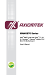
1
COMFORT CALL SYSTEM
ACC0433
Comfort
Call
Allows simple remote control of your
thermostat through the telephone
Cell phon compatible
Voice recognition or touch-tone entry
Announces indoor & outdoor
temperatures*
Announces thermostat status i.e. “heat is running”
Wireless technology - (easy to install)
Can control up to 4 thermostats
May control 1 auxiliary output
Base Station &
Wireless Module
Compatible with thermostat models:
T1700, T1800, T1900, T2700, T2800 T2900
Consult VENSTAR for a complete list.
* Optional compatible outdoor sensor required
OWNER’S
MANUAL
Venstar Inc. 08/07
Table of Contents
Overview
Location of Controls, Indicators
& Connections
Installation & Setup
Resetting the Access Code
Operation
Link up to 4 Thermostats to
1 Base Station
Control of the Thermostat’s
Auxiliary Output
Menu of Touch Tone Keys
User Cautions
Warranty
This device complies with Part 15 of the FCC Rules. Operation is
subject to the following two conditions: (1) this device may not cause
harmful interference, and (2) this device must accept any interference
received, including interference that may cause undesired operation.
Venstar Inc. 08/07
P/N ACC0433
Page 1
c
FC
Comfort Call
ACC0433
FCC ID MUHBASE1
FCC ID MUHMODULE1
Overview
Comfort Call allows you to call and ‘talk’ to your compatible thermostat. Monitoring
and controlling your thermostat is now simple and easy from any phone, from
anywhere.
Comfort Call employs the latest in voice recognition and synthesis technology. It can
tell you the indoor temperature of your home and the outdoor temperature, provided
there is a working outdoor sensor connected to the thermostat. Once on the phone
with your system, you may tell your thermostat to change to your preset Comfort
Settings or go into your preset ‘unoccupied’, Energy Savings Settings (page 15).
Comfort Call consists of two parts: A base station (page 6) that connects to the phone
line and a RF Wireless Module that plugs into your compatible thermostat (page 5).
Once Comfort Call answers, you will be prompted to enter a Security Access Code.
This code is preset to 1111. You may change this code to any four digit number, if
desired (page 13).
Some homes may have more than one thermostat. If there is more than one
thermostat, Comfort Call will have a menu option to access up to four different
thermostats (page 16).
As an added feature, some of our compatible thermostat models allow for the remote
control of an auxiliary output on the thermostat. This auxiliary output may be
accessed and controlled from Comfort Call as well (pages 17 and 18). An example of the
use of this auxiliary output: The output is connected to a Powerflash Interface PF284
to turn on or off the indoor lighting wirelessly.
Page 2
Overview cont.
Comfort Call requires an analog telephone line. If this system is installed at a primary
residence, then the ring selector on the base station should be set to pick up the line
after seven rings (page 10). With this setting, Comfort Call will not answer before an
occupant is likely to pick up the phone.
If an answering machine or fax machine is connected to Comfort Call, then the
answering/fax machine should be set to pick up before Comfort Call (the ring selector
is set to seven rings). In the case of a connected answering machine, after the tone to
leave a message is heard, the user enters the Comfort Call security code. Comfort
Call will release the answering machine from the line and control of the thermostat is
now possible.
In the case of a fax machine, after the ‘handshake’ tones are heard, there are
moments of silence; during this silent period the Comfort Call security code should be
entered. Comfort Call will release the fax machine from the line and control of the
thermostat will be possible.
Please note that some phone services provide a ‘voicemail’ answering service. These
services release the home phone line after a preset number of rings and transfer the
call to an internal voicemail system. Comfort Call is not compatible with this type of
voicemail system.
Comfort Call is a solution for people who do not have the same occupied patterns
every day for their homes. It is also a convenient way to call ahead to make
sure the primary or vacation home is comfortable upon arrival.
Page 3
Location of Controls, Indicators & Connections
Power and Link LED Indicator
Energy Savings Link Button
Comfort Settings Link Button
COMFORT CALL
Ring Selector Switch
Link Button
Link LED Indicator
1 At the thermostat, select the mode (Auto,
Heat, Cool, or Off).
corresponding button for 5
seconds. The LED will flash for
5 minutes.
4 Within 5 minutes of pressing
the button on the base station,
press the link button on the receiver for 3 seconds. The
LED on the receiver will flash twice.
energy
comfort
MADE IN CHINA
7
YYWWXXXX
4
US:J3CTE02ABASE1
1
MODEL: ACC0433
RINGS
2 Adjust the setpoints to the desired setting.
3 Here, at the base station, press the
The base station will now remember your settings. You
may change these settings at anytime by repeating the
above steps.
Refer to Owner’s Manual for more details
LINE
Page 4
ANSWER MACH., 9vac Power
FAX, OR PHONE
Installation & Setup
Connect the RF Wireless Module to the thermostat as shown below.
PLATINUM
eries
COMMERCIAL PROGRAMMABLE THERMOSTAT
I2:00
74
Pm
Su
COOL
AUTO
72
HEAT
MODE
HUMIDITY
SET CLOCK
FAN
PROGRAM HOLIDAY OVERRIDE
OUTDOOR
Accessory release button
Accessory jack located
on bottom of thermostat
RF Wireless Module
To connect the RF Wireless Module to the thermostat, insert the RF Wireless
Module plug into the accessory jack of the thermostat. The RF Wireless Module
has two tabs that fit into the ventilation slots of the thermostat for added stability.
To remove the RF Wireless Module from the thermostat, press and hold the
accessory release button while removing the RF Wireless Module from the
thermostat’s accessory jack.
Page 5
Installation & Setup cont.
Connect the telephone line to the Base Station and power Comfort Call
with the provided power supply, as shown below. The power indicator
LED will glow green when power is connected.
Base Station
To 110vac
9vac
Output
House
Telephone
Line
Answering Machine,
Fax or Phone*
*A phone, answering or fax machine is not required
‘Link’ the thermostat to the Base Station for COMFORT SETTINGS.
1 At the thermostat, select the mode you would like your
Comfort Settings to operate in: Auto, Heat, or Cool.
2 Adjust the set points to the desired Comfort Settings.
PLATINUM
eries
COMMERCIAL PROGRAMMABLE THERMOSTAT
I2:00
74
Pm
Su
COOL
AUTO
72
HEAT
FAN
SET
OUTSIDE HUMIDITY PROGRAM CLOCK
VACATION
MODE
MODE
HUMIDITY
SET CLOCK
FAN
PROGRAM HOLIDAY OVERRIDE
OUTDOOR
Page 6
Set the
2 temperature(s)
1
Select
the Mode
Installation & Setup cont.
3 At the Base Station, press the Comfort Settings link button for five seconds.
The green power LED next to the button will turn red and flash for
up to five minutes.
1 At the thermostat, select the mode (Auto,
Heat, Cool, or Off).
corresponding button for 5
seconds. The LED will flash for
5 minutes.
4 Within 5 minutes of pressing
the button on the base station,
press the link button on the receiver for 3 seconds. The
LED on the receiver will flash twice.
energy
comfort
MADE IN CHINA
7
YYWWXXXX
4
US:J3CTE02ABASE1
1
MODEL: ACC0433
RINGS
2 Adjust the setpoints to the desired setting.
3 Here, at the base station, press the
3
The base station will now remember your settings. You
may change these settings at anytime by repeating the
above steps.
Refer to Owner’s Manual for more details
4 Go to the thermostat, making sure that it is still set to your Comfort Settings.
Within five minutes of pressing the link button on the Base Station, press the
link button on the side of the RF Wireless Module for three seconds. The
LED on the RF Wireless Module will flash indicating the following:
2 flashes indicates that the link was successful
5 flashes indicates the communication was good, but the
thermostat was not in the appropriate mode; only
Auto, Heat and Cool are supported
10 flashes indicates a communication problem
After two flashes on the RF Wireless Module, the Base Station will remember
your Comfort Settings. You may change these settings at anytime by
repeating the above steps.
PLATINUM
4
eries
COMMERCIAL PROGRAMMABLE THERMOSTAT
I2:00
Link Button
74
Pm
Su
COOL
AUTO
72
HEAT
MODE
HUMIDITY
SET CLOCK
FAN
PROGRAM HOLIDAY OVERRIDE
OUTDOOR
LED
Side View
Page 7
Installation & Setup cont.
‘Link’ the thermostat to the Base Station for ENERGY SAVINGS
SETTINGS.
Energy Savings Settings are normally used for unoccupied
periods.
1 At the thermostat, select the mode you would like your Energy Savings
Settings to operate in: Auto, Heat, Cool or Off.
2 Adjust the set points to the desired Energy Savings Settings.
PLATINUM
Set the
2 temperature(s)
eries
COMMERCIAL PROGRAMMABLE THERMOSTAT
I2:00
74
Pm
Su
72
HEAT
MODE
HUMIDITY
FAN
Select
the Mode
1
COOL
AUTO
PROGRAM HOLIDAY OVERRIDE
SET CLOCK
OUTDOOR
3 At the Base Station, press the Energy Savings Settings link button for five
seconds. The green power LED next to the button will turn red and flash for
up to five minutes.
1 At the thermostat, select the mode (Auto,
Heat, Cool, or Off).
corresponding button for 5
seconds. The LED will flash for
5 minutes.
4 Within 5 minutes of pressing
the button on the base station,
press the link button on the receiver for 3 seconds. The
LED on the receiver will flash twice.
energy
comfort
The base station will now remember your settings. You
may change these settings at anytime by repeating the
above steps.
Refer to Owner’s Manual for more details
Page 8
MADE IN CHINA
7
YYWWXXXX
4
US:J3CTE02ABASE1
1
2 Adjust the setpoints to the desired setting.
3 Here, at the base station, press the
MODEL: ACC0433
RINGS
3
Installation & Setup cont.
4 Go to the thermostat, making sure that it is still set to your Energy Savings
Settings. Within five minutes of pressing the link button on the Base Station,
press the link button on the side of the RF Wireless Module for three
seconds. The LED on the RF Wireless Module will flash indicating the
following:
2 flashes indicates that the link was successful
5 flashes indicates the communication was good, but the
thermostat was not in the appropriate mode; only
Auto, Heat, Cool and Off are supported
10 flashes indicates a communication problem
After two flashes on the RF Wireless Module, the Base Station will remember
your Energy Savings Settings. You may change these settings at anytime by
repeating the above steps.
PLATINUM
4
eries
COMMERCIAL PROGRAMMABLE THERMOSTAT
I2:00
Link Button
74
Pm
Su
COOL
AUTO
72
HEAT
MODE
HUMIDITY
SET CLOCK
FAN
PROGRAM HOLIDAY OVERRIDE
OUTDOOR
LED
Side View
Notes on the linking procedure
The linking procedure may be cancelled by pressing the Base Station’s link
button (Comfort or Energy) while its LED is flashing red
If Comfort Call is accessed by phone, when no thermostats are linked, it
will immediately prompt you to exit the system
To change the Comfort or Energy Savings settings, simply repeat the link
procedure; the new settings will replace the previous settings
Page 9
Installation & Setup cont.
Set the # of rings before the Base Station will pick up.
1 Slide the RINGS switch to 7 rings if you have an answering machine or fax
machine connected. In this setting, the answering/fax machine may answer
the call first. If there is no answering machine connected, choose 1, 4, or 7
rings before the Base Station answers the call.
If there is an answering or fax machine in the house, it is highly recommended
that these items are connected to the Base Station. While the answering
machine plays your greeting, or after the fax tones stop, you may enter your
access code. After Comfort Call accepts your security access code, it will
bypass the answering or fax machine to control your thermostat.
1
1 At the thermostat, select the mode (Auto,
Heat, Cool, or Off).
corresponding button for 5
seconds. The LED will flash for
5 minutes.
4 Within 5 minutes of pressing
the button on the base station,
press the link button on the receiver for 3 seconds. The
LED on the receiver will flash twice.
energy
comfort
The base station will now remember your settings. You
may change these settings at anytime by repeating the
above steps.
Refer to Owner’s Manual for more details
Page 10
MADE IN CHINA
7
YYWWXXXX
4
US:J3CTE02ABASE1
1
2 Adjust the setpoints to the desired setting.
3 Here, at the base station, press the
MODEL: ACC0433
RINGS
Installation & Setup cont.
If it becomes necessary to unlink the thermostat(s) from the Base Station,
follow these steps:
Press the desired link button (Comfort or Energy) for five seconds. When the LED
begins flashing red, release the link button.
1 At the thermostat, select the mode (Auto,
Heat, Cool, or Off).
2 Adjust the setpoints to the desired setting.
3 Here, at the base station, press the
corresponding button for 5
seconds. The LED will flash for
5 minutes.
energy
comfort
MADE IN CHINA
7
4 Within 5 minutes of pressing
the button on the base station,
press the link button on the receiver for 3 seconds. The
LED on the receiver will flash twice.
YYWWXXXX
4
US:J3CTE02ABASE1
1
MODEL: ACC0433
RINGS
The base station will now remember your settings. You
may change these settings at anytime by repeating the
above steps.
Refer to Owner’s Manual for more details
Press and hold the same desired link button for another five seconds. When the LED
begins flashing rapidly, release the link button.
Press and hold the link button on the RF Wireless Module for three seconds. The RF
Wireless Module’s flashing LED will indicate the status:
2 flashes indicate the unlink was successful.
10 flashes indicate a communication problem or the RF Wireless Module was not
linked to the Base Station.
PLATINUM
eries
COMMERCIAL PROGRAMMABLE THERMOSTAT
I2:00
74
Pm
Su
COOL
AUTO
72
HEAT
MODE
HUMIDITY
SET CLOCK
FAN
PROGRAM HOLIDAY OVERRIDE
OUTDOOR
Side View
Notes on the unlinking procedure
After the unlinking process is complete, the Base Station’s LED stops flashing
The unlink mode remains active for five minutes
The unlinking procedure may be cancelled by pressing the Base Station’s link button
(Comfort or Energy) while its LED is flashing red
Page 11
Installation & Setup cont.
If it becomes necessary to reset the link database for any reason (such as
relocating the Comfort Call Base Station to a new location with different
thermostats) follow these steps to clear its memory of linked thermostats:
Remove power from the Base Station.
Press and hold both the Comfort & Energy settings buttons.
Apply power while continuing to hold the buttons.
After the reset is complete (about three seconds) the power LED will flash once.
Release the buttons.
Note: All linked information is stored in the Base Station, so only the
Base Station needs to be reset.
,
1 At the thermostat, select the mode (Auto,
Heat, Cool, or Off).
corresponding button for 5
seconds. The LED will flash for
5 minutes.
4 Within 5 minutes of pressing
the button on the base station,
press the link button on the receiver for 3 seconds. The
LED on the receiver will flash twice.
energy
comfort
The base station will now remember your settings. You
may change these settings at anytime by repeating the
above steps.
Refer to Owner’s Manual for more details
Page 12
MADE IN CHINA
7
YYWWXXXX
4
US:J3CTE02ABASE1
1
MODEL: ACC0433
RINGS
2 Adjust the setpoints to the desired setting.
3 Here, at the base station, press the
,
Resetting the Access Code
Comfort Call is shipped from the factory with the Security Access Code set to
1111. A custom four digit code may be programmed to replace the default
code. To set a custom access code follow these steps:
Remove power from the Base Station.
Press the Energy button.
Apply power while continuing to hold the Energy button.
Release the Energy button.
Place a call to the Comfort Call Base Station.
When the Comfort Call prompts for an access code, enter the desired four digit
access code.
After the access code has been entered, Comfort Call will read the new access
code back, and disconnect.
Note: The new access code will be in effect for all future calls.
The default Security Access Code may be restored by repeating
the above procedure, or by preforming the database reset procedure.
, ,
,
VENSTAR INC
.
Comfort
Call
1 At the thermostat, select the mode (Auto,
Heat, Cool, or Off).
2 Adjust the setpoints to the desired setting.
3 Here, at the base station, press the
TALK
OFF
corresponding button for 5
seconds. The LED will flash for
5 minutes.
4 Within 5 minutes of pressing
the button on the base station,
press the link button on the receiver for 3 seconds. The
LED on the receiver will flash twice.
energy
comfort
MADE IN CHINA
7
YYWWXXXX
4
US:J3CTE02ABASE1
1
MODEL: ACC0433
RINGS
MENU
The base station will now remember your settings. You
may change these settings at anytime by repeating the
above steps.
Refer to Owner’s Manual for more details
,
SAD;L
KJS
1
4
GHI
7
PAUSE/RED
IAL
2
ABC
JKL
5
3
DEF
8
Comf
ort
Call
Vensta
r Inc.
6
MNO
PQRS
*
TUV
0
9
WXYZ
#
FLASH
CALL WAIT
HOLD
IN USE
COMFORT
CA
L
L
CHARGE
Page 13
Operation
Dial the phone number connected to your Comfort Call system.
The Base Station will answer your call after a predetermined number of rings
(page 10).
The greeting will prompt you to enter your Security Access Code. Voice
recognition does not work to enter this code, you must use the telephone keypad.
Status Report: After your access code is accepted, the status of the
thermostat/equipment will be announced as follows:
You are controlling thermostat number 1 (2, 3 or 4)*
The inside temperature is xx degrees
The outside temperature is yy degrees**
The thermostat is in (Heat, Cool, Auto, Program or Off) and (is Idle, the Heat
is running or the Cool is running)
The auxiliary output is now on/off***
Main Menu: The Base Station will give you the following options:
For Comfort Settings press 1 or say: Comfort Settings
For Energy Savings Settings press 2 or say: Energy Savings
To control the Auxiliary Output, press 3 or say: Auxiliary Output***
To control the next thermostat, press 4 or say: Next Thermostat*
To leave your thermostat and hang up, press 9 or say: Hang Up
To return to the Main Menu, press 0 or say: Main Menu
*This announcement will only occur if more than one thermostat is linked to the
Base Station (page 16).
**The outdoor temperature will only be announced if an outdoor sensor is connected.
***The status of the Auxiliary Output will only be announced if Comfort Call has been
configured to control the thermostat’s auxiliary output (page 17 and 18).
Page 14
Operation cont.
Comfort Call will ask you to confirm your selection:
Comfort Settings:
Comfort Call will say, “You have selected ‘Comfort Settings’, is this correct?”
To confirm your selection press 1 or say: “Yes” and Comfort Call will say,
“Okay, Comfort Settings are active.”
To cancel your selection and return to the Main Menu press 2 or say: “No”*
Energy Savings:
Comfort Call will say, “You have selected ‘Energy Savings’, is this correct?”
To confirm your selection press 1 or say: “Yes” and Comfort Call will say,
“Okay, Energy Savings are active.”
To cancel your selection and return to the Main Menu press 2 or say: “No”*
Auxiliary Output**:
Comfort Call will say, “The auxiliary output is now (on/off), would you like to
turn it (off/on)?”
To turn the Auxiliary Output (on/off) press 1 or say: “Yes” and Comfort
Call will say, “The Auxiliary Output will now be turned (on/off), is this correct?”
To cancel your selection and return to the Main Menu press 2 or say: “No”*
To confirm your selection press 1 or say: “Yes” and Comfort Call will say,
“Okay, the Auxiliary Output is now (on/off).”
*If “No” is selected, Comfort Call will ‘beep’ prompting you to make another selection.
**The status of the Auxiliary Output will only be announced if Comfort Call has been
configured to control the thermostat’s auxiliary output (page 17 and 18).
Notes on the phone system
Comfort Call will not accept voice commands until the user is prompted with a ‘beep’
Comfort will accept button presses from your touchtone phone at any time, even while
the system is speaking
Page 15
Link up to 4 Thermostats to 1 Base Station
Comfort Call will allow up to four thermostats to be linked with one Base Station.
This can be accomplished with additional RF Wireless Modules (ACC0434) installed at
each additional thermostat. The linking procedure for thermostats numbered two
through four is the same as described for a single thermostat (pages 6-9).
The Base Station will recognize the new thermostats and store them by number, in
the order that they are linked to the Base Station.
When more than one thermostat is linked, the main menu will add the prompt, “For
the next thermostat, press four, or say next thermostat.” Additionally, before the
status is given, the thermostat will say, “You are controlling thermostat number 1 (2,
3, or 4)” (page 14).
Page 16
Control of the Thermostat’s Auxiliary Output
Comfort Call has the ability to control the Auxiliary Output of a connected thermostat
if that thermostat has an Auxiliary Output configured for PROG (program) operation.
When the thermostat is configured and enabled to let Comfort Call control its
Auxiliary Output, the Base Station will automatically detect this. The main menu will
then add the prompt, “To control the Auxiliary Output, press 3 or say: Auxiliary
Output” (page 14).
After pressing 3 or saying, “Auxiliary Output,” the user will be given the Auxiliary
Output Status and asked if he/she wants to change it. This will be followed by a
confirmation (page 15). Additionally, the Auxiliary Output Status will be added to the
status report.
Please consult the thermostat’s Owner’s Manual for further details on configuring the
thermostat for this operation.
The auxiliary output of the thermostat may be connected to a 24v control module,
such as a X-10 Powerflash Interface, model PF284 (recommended wiring diagrams on, pages
18-20). This will give you the ability to control items such as lamps, wall switches,
jacuzzis, appliances, hot water heaters, security systems, etc. in your home with
minimal installation.
To see available X-10 products that can be controlled with a Powerflash Interface
PF284 contact or visit a retailer that carries X-10 products, such as SmartHome
(800.762.7846 or www.SmartHome.com).
Page 17
Control of the Thermostat’s Auxiliary Output cont.
Connect the thermostat to the Powerflash Interface as follows:
POWERFLASH
INTERFACE
PF284
TEST
ALL UNITS OFF
1
A
5
13
M
E
I
9
UNIT CODE
HOUSE CODE
X-10 POWERHOUSE
POWERFLASH
INTERFACE
INPUT
A B
MODE
1 2 3
Input terminals
Select Input A on the Powerflash Interface.
Select the proper mode for your desired operation:
1 Turns on all lights connected to Lamp Modules and
Wall Switch Modules, and turns on a selected
Appliance Module.
2 Flashes all lights connected to Lamp Modules and
Wall Switch Modules.
3 Turns on a selected Module with the same house
and unit code as the Powerflash Interface.
Locate the input terminals on the Powerflash Interface.
POWERFLASH
INTERFACE
PF284
TEST
ALL UNITS OFF
1
A
5
13
9
UNIT CODE
M
E
I
HOUSE CODE
X-10 POWERHOUSE
POWERFLASH
INTERFACE
INPUT
A B
MODE
1 2 3
Connect one end of the supplied resistor to the screw
input terminal of the Powerflash Interface. The
supplied resistor will then be wired ‘in-line’ with either
the MISC1, MISC2 or MISC3 output (depending on
which is set to PROG) or the C wire (see next page). It
does not matter which of the two wires you choose.
The resistor is 4.7k ohm, 1/4 watt.
Page 18
Control of the Thermostat’s Auxiliary Output cont.
Connect the wires as shown. Since the MISC1, MISC2 or MISC3 terminal is a
24 vac output, it does not matter which of the two input screw terminals, on
the Powerflash Interface, it is connected to.
POWERFLASH
INTERFACE
PF284
TEST
ALL UNITS OFF
1
A
5
13
9
UNIT CODE
M
E
I
HOUSE CODE
X-10 POWERHOUSE
POWERFLASH
INTERFACE
W2
MISC1
RS2
MISC3
RS+5
RS1
RSGND
MODE
1 2 3
SUPPLIED
RESISTOR
W1/O/B
Y1
G
MISC2
CK1
CKGND
R
C
24 vac return
R
fan relay
G
24 vac common
C
THERMOSTAT BASEPLATE
compressor relay
W1 Y1
INPUT
A B
FURNACE BOARD
Page 19
Control of the Thermostat’s Auxiliary Output cont.
120V
WALL OUTLET
Plug the Powerflash Interface into a 120 vac receptacle.
TEST
ALL UNITS OFF
1
A
5
13
9
UNIT CODE
M
E
I
HOUSE CODE
X-10 POWERHOUSE
POWERFLASH
INTERFACE
PF284
POWERFLASH
INTERFACE
INPUT
A B
W2
MISC1
RS2
MISC3
RS+5
RS1
RSGND
MODE
1 2 3
SUPPLIED
RESISTOR
W1/O/B
Y1
G
MISC2
CK1
CKGND
R
C
24 vac return
R
fan relay
G
compressor relay
W1 Y1
24 vac common
C
THERMOSTAT BASEPLATE
FURNACE BOARD
Connect and plug in the X-10 device(s) to be controlled with Comfort Call and your
thermostat. Make sure the house and unit codes are adjusted per the X-10
instruction manual(s) that are supplied with each X-10 device.
Page 20
Menu of Touch Tone Keys
Comfort
Settings
or
YES
Energy Savings
Settings
or
NO
Status Report
or
Next Thermostat*
Auxiliary
Output
Settings*
Exit System
(Hang Up)
RF Link
Signal Strength
(1-10)
*When applicable
Main Menu
*When applicable
Page 21
User
Cautions and Information
Use 26 AWG or larger telephone wire to reduce the risk of fire.
Never install telephone wiring during a lightning storm.
Never install telephone jacks in wet locations unless the jack is specifically designed for wet locations.
Never touch uninsulated telephone wires or terminals unless the telephone line has been disconnected at the network
interface.
Use caution when installing or modifying telephone lines.
Avoid using the telephone (other than cordless type) during an electrical storm. There may be a remote risk of
electric shock from lightning.
Do no use the telephone to report a gas leak in the vicinity of the leak.
This equipment has been tested and found to comply with the limits for a Class B digital device, pursuant to part 15 of
the FCC Rules. These limits are designed to provide reasonable protection against harmful interference in a
residential installation. This equipment generates, uses and can radiate radio frequency energy and, if not installed and
used in accordance with the instructions, may cause harmful interference to radio communications. However, there is
no guarantee that interference will not occur in a particular installation. If this equipment does cause harmful
interference to radio or television reception, which can be determined by turning the equipment off and on, the user is
encouraged to try to correct the interference by one or more of the following measures: Reorient or relocate the
receiving antenna; increase the separation between the equipment and receiver; connect the equipment into an outlet
on a circuit different from that to which the receiver is connected; consult the dealer or an experienced radio/TV
technician for help. The user that makes changes or modifications not expressly approved by Totaline could void the
user’s authority to operate the equipment.
This equipment complies with Part 68 of the FCC rules and the requirements adopted by the ACTA. On the bottom
face of this equipment is a label that contains, among other information, the product identifier US:J3CTE02ABASE1. If
requested, this number must be provided to the Telephone company.
The Universal Service Order Code (USOC) for Comfort Call’s jack is RJ11C, the Facility Interface Code (FIC) is
02LS2, and the Service Order Code (SOC) is 9.0Y.
A plug and jack used to connect this equipment to the premises wiring and telephone network must comply with the
applicable FCC Part 68 rules and requirements adopted by the ACTA. A compliant telephone cord and modular plug
is provided with this product. It is designed to be connected to a compatible modular jack that is also compliant. See
page 6 of this manual for details. The REN is used to determine the number of devices that may be connected to a
telephone line. Excessive RENs on a telephone line may result in the devices not ringing in response to an incoming
call. In most but not all areas, the sum of RENs should not exceed five (5.0). To be certain of the number of devices
that may be connected to a line, as determined by the total RENs, contact the local telephone company. The REN for
this product is 0.2 as shown in the product identifier US:J3CTE02ABASE1. The digits 02 are the REN without a
decimal point (e.g., 02 is a REN of 0.2).
The telephone company may make changes in its facilities, equipment, operations or procedures that could affect the
operation of the equipment. If this happens the telephone company will provide advance notice in order for you to
make necessary modifications to maintain uninterrupted service.
If trouble is experienced with Comfort Call, for repair or warranty information, please contact the qualified HVAC
technician that installed Comfort Call in your home. If the equipment is causing harm to the telephone network, the
telephone company may request that you disconnect the equipment until the problem is resolved.
In the unlikely event that Comfort Call ceases to operate correctly, please do not attempt to repair Comfort Call. For
repair or warranty information, contact the qualified HVAC technician that installed Comfort Call in your home.
Connection to party line service is subject to state tariffs. Contact the state public utility commission, public service
commission or corporation commission for information.
If your home has specially wired alarm equipment connected to the telephone line, ensure the installation of Comfort
Call does not disable your alarm equipment. If you have questions about what will disable alarm equipment, consult
your telephone company or a qualified installer.
Page 22
Warranty
One-Year Warranty - This Product is warranted to be free from defects in material and workmanship. If it appears within
one year from the date of original installation, whether or not actual use begins on that date, that the product does not
meet this warranty, a new or remanufactured part, at the manufacturer’s sole option to replace any defective part, will
be provided without charge for the part itself provided the defective part is returned to the distributor through a qualified
servicing dealer.
THIS WARRANTY DOES NOT INCLUDE LABOR OR OTHER COSTS incurred for diagnosing, repairing, removing, installing,
shipping, servicing or handling of either defective parts or replacement parts. Such costs may be covered by a
separate warranty provided by the installer.
THIS WARRANTY APPLIES ONLY TO PRODUCTS IN THEIR ORIGINAL INSTALLATION LOCATION AND BECOMES VOID UPON
REINSTALLATION.
LIMITATIONS OF WARRANTIES – ALL IMPLIED WARRANTIES (INCLUDING IMPLIED WARRANTIES OF FITNESS FOR A PARTICULAR
PURPOSE AND MERCHANTABILITY) ARE HEREBY LIMITED IN DURATION TO THE PERIOD FOR WHICH THE LIMITED WARRANTY IS
GIVEN. SOME STATES DO NOT ALLOW LIMITATIONS ON HOW LONG AN IMPLIED WARRANTY LASTS, SO THE ABOVE MAY NOT
APPLY TO YOU. THE EXPRESSED WARRANTIES MADE IN THIS WARRANTY ARE EXCLUSIVE AND MAY NOT BE ALTERED, ENLARGED,
OR CHANGED BY ANY DISTRIBUTOR, DEALER, OR OTHER PERSON WHATSOEVER.
ALL WORK UNDER THE TERMS OF THIS WARRANTY SHALL BE PERFORMED DURING NORMAL WORKING HOURS. ALL
REPLACEMENT PARTS, WHETHER NEW OR REMANUFACTURED, ASSUME AS THEIR WARRANTY PERIOD ONLY THE REMAINING TIME
PERIOD OF THIS WARRANTY.
THE MANUFACTURER WILL NOT BE RESPONSIBLE FOR:
1. Normal maintenance as outlined in the installation and servicing instructions or owner’s manual, including filter
cleaning and/or replacement and lubrication.
2. Damage or repairs required as a consequence of faulty installation, misapplication, abuse, improper servicing,
unauthorized alteration or improper operation.
3. Failure to start due to voltage conditions, blown fuses, open circuit breakers or other damages due to the
inadequacy or interruption of electrical service.
4. Damage as a result of floods, winds, fires, lightning, accidents, corrosive environments or other conditions beyond
the control of the Manufacturer.
5. Parts not supplied or designated by the Manufacturer, or damages resulting from their use.
6. Manufacturer products installed outside the continental U.S.A., Alaska, Hawaii, and Canada.
7. Electricity or fuel costs or increases in electricity or fuel costs for any reason whatsoever including additional or
unusual use of supplemental electric heat.
8. ANY SPECIAL INDIRECT OR CONSEQUENTIAL PROPERTY OR COMMERCIAL DAMAGE OF ANY NATURE WHATSOEVER.
Some states do not allow the exclusion of incidental or consequential damages, so the above may not apply to you.
This warranty gives you specific legal rights and you may also have other rights which may vary from state to state.
P/N 88-624 Rev. 1
Page 23