1
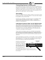
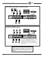
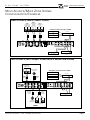
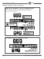
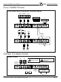
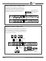
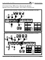
660
MULTI-CHANNEL
POWER AMPLIFIER
Installation Manual
ELAN
HOME
SYSTEMS
WARNING
RISK OF ELECTRIC SHOCK
DO NOT OPEN
CAUTION: TO REDUCE THE RISK OF ELECTRIC SHOCK, DO NOT
REMOVE COVER (OR BACK). NO USER SERVICEABLE PARTS INSIDE.
REFER SERVICING TO QUALIFIED SERVICE PERSONNEL.
The lightning flash with arrowhead symbol within an equilateral triangle
is intended to alert the user to the presence of uninsulated “dangerous
voltage” within the product’s enclosure that may be of sufficient
magnitude to constitute a risk of electric shock to persons.
The exclamation point within an equilateral triangle is intended to alert
the user to the presence of important operating and maintenance
(servicing) instructions in the literature accompanying the device or component.
WARNING: TO REDUCE THE RISK OF FIRE OR SHOCK,
DO NOT EXPOSE THIS APPLIANCE TO RAIN OR MOISTURE.
660
HOMEOWNERS MANUAL
IMPORTANT SAFETY
INFORMATION
Read Information—All the safety and operating information should be
read before the unit is operated.
Follow Information—All operating and use information should be followed.
Retain Information—The safety and operating information should be
retained for future reference.
Heed Warnings—All warnings on the unit and in the operating instructions
should be heeded.
Carts and Stands—This unit should be used with a stationary shelf. Do
not use any mobile carts.
Wall Mounting—Mounting of this unit should be done only by an authorized
installer.
Ventilation—This unit should be situated so that its location or position does not interfere with proper ventilation. This unit should never be placed near or over a
radiator or heat register. This unit should not be placed in a built-in installation such as a bookcase or cabinet that may impede the flow of air through the ventilation openings.
Do not “rack mount” two or more amplifiers on top of each other without either forced-air ventilation or one rack space (1.75”) between each unit.
Non-Use Periods—Units that are left unattended and unused for long periods of time should be unplugged from the wall outlet.
Power Sources—This unit should be connected to a power supply only of the type described in the operating instructions or as marked on each unit. If you are
not sure of the type of power supply to your home, consult your authorized ELAN dealer or local power company.
Grounding or Polarization—These audio products are equipped with a grounding-type alternating-current line plug. This plug will fit only into a grounding-type power receptacle. This is a safety feature. If the plug receptacle does not fit, contact an electrician to replace your
obsolete receptacle. Do not defeat the safety purpose of the grounding-type plugs.
Water and Moisture—To reduce the risk of electric shock or fire, these appliances should not be used near water - for example, near a bathtub, washbowl,
kitchen sink, laundry tub, in a wet basement, or near a swimming pool.
Power Cord Protection—Power supply cords should be routed so that they are not likely to be walked on or pinched by items placed upon or against
them, paying particular attention to cords at plugs, convenience receptacles, and the point where they exit from the appliances.
Do not damage or deform the power supply cord. If it is damaged or deformed, it may cause electric shock or fire when used. When removing from the wall outlet, be sure to
remove by holding the plug attachment and not by pulling the cord.
Telephones—Avoid using a telephone (other than a cordless type) during an electrical storm. There may be a remote risk of electrical shock from lightning. Do not
use a telephone to report a gas leak if the leak is in the vicinity of the ELAN electronic equipment because of risk of fire or explosion.
Cleaning—Unplug this audio product from the wall outlet before cleaning. Do not use liquid or aerosol cleaners. Use a damp cloth for cleaning.
Overloading—Do not overload wall outlets and extension cords, as this could result in fire or electric shock.
Object and Liquid Entry—Never insert objects of any kind through the openings of these appliances, as they may touch dangerous voltage points or
short-out parts that could result in a fire or electric shock. Care should be taken so that objects do not fall and liquids are not spilled into the appliance through openings in the
enclosure.
Servicing—Do not attempt to service these appliances yourself, as opening or removing covers may expose you to dangerous voltage or other hazards. Refer all servicing to qualified service personnel.
Damage Requiring Service—These appliances should be serviced by qualified service personnel when:
• A power supply cord or a plug has been damaged or
• If liquid has been spilled into the appliance or objects have fallen into the appliance or
• The appliance has been exposed to water or moisture or
• The appliance does not appear to operate normally or exhibits a marked change in performance or
• The appliance has been dropped or the enclosure damaged.
Replacement Parts—When replacement parts are required, be sure the service technician has used replacement parts
specified by the manufacturer or that have the same characteristics as the original part. Unauthorized substitutions may result in fire,
electric shock, or other hazards. The Master Control Unit battery should be replaced only after turning the power off and only by an authorized installer.
Safety Check—Upon completion of any service or repairs to this audio product, ask the service technician to perform safety checks to determine that the audio product is in proper operating condition.
Lightning—For added protection for these audio products during an electrical storm, or when they are left unattended and
unused for long periods of time, unplug them from the wall outlet and disconnect the antenna or cable system. This will prevent damage
to the audio products due to lightning and power-line surges.
9700721
HOME SYSTEMS WITH AUDIO AND/OR
VIDEO CONTROL CAPABILITIES
ETL LISTED PRODUCT
CONFORMS TO UL STD 6500.
AUDIO/VIDEO AND MUSICAL INSTRUMENT
APPARATUS FOR HOUSEHOLD, COMMERCIAL,
AND SIMILAR USE.
ETL LISTED PRODUCT.
CONFORMS TO CAN/CSA E65-94.
ELAN
HOME
SYSTEMS
660
CONGRATULATIONS
AND
INSTALLATION MANUAL
THANK YOU
You have purchased the highest quality multi-channel audio amplifier on the
market today––the Z•660 power amplifier. We at ELAN Home Systems are proud
of this precision audio component and are pleased you have chosen this ELAN
product as the cornerstone to your audio system. Crafted to be the de facto
standard for power amplifiers in its class, the Z•660’s circuit design, small
footprint and robust power output are the latest in audio technology and should
provide you with years of superior audio performance.
As a manufacturer, ELAN strives to provide you with excellent service after the
sale. If you have any questions or comments concerning the performance,
installation or features of the Z•660 power amplifier, please call the ELAN Service
and Technical Support Department at 1 606 269-7760. We are at your service.
Please take a few minutes to read this manual thoroughly. It will help you fully
understand and successfully integrate the capabilities and features of your new
power amplifier with your existing source equipment and speakers.
ELAN Home Systems designs and manufactures the industry’s most complete line
of multi-room audio/video systems and components. For free product information
write us at:
ELAN Home Systems
Product Information
2428 Palumbo Drive
Lexington, Kentucky 40509
or check out our website at: www.elanhomesystems.com
Look for these other New Z•Series Products:
Z•630 Pre-Amp Controller
Z•600 Comm Controller
Z•300 Two-Channel Power Amplifier
Z•100 and Z•150 Intelligent Keypads
Z•FAN System Cooling Component
Z•880 Video Controller
TABLE
OF
CONTENTS
Introduction . . . . . . . . . . . . . . . . . . . . . . . . . . . . . . . . . . . . . . . . . . . . .2
Z•660 Front and Back Illustrations . . . . . . . . . . . . . . . . . . . . . . . . . . . .2
Features . . . . . . . . . . . . . . . . . . . . . . . . . . . . . . . . . . . . . . . . . . . . . .3-4
Installing Your Z•660 Power Amplifier . . . . . . . . . . . . . . . . . . . . . . . . .4
Connecting Speakers . . . . . . . . . . . . . . . . . . . . . . . . . . . . . . . . . . . . .4-5
Connecting Volume Controls . . . . . . . . . . . . . . . . . . . . . . . . . . . . . . .5-6
Single-Source/Wholehouse System Configuration Examples . . . . . . . .7-8
Single-Source/Wholehouse System Configuration Examples . . . . . . . .7-8
Multi-Source/Multi-Zone System Configuration Examples . . . . . . . . . . .9
Home Theater Applications . . . . . . . . . . . . . . . . . . . . . . . . . . . . . . . . .10
Other Connections . . . . . . . . . . . . . . . . . . . . . . . . . . . . . . . . . . . .10-11
Connecting Multiple Speakers Using Impedance Selectable
Volume Controls . . . . . . . . . . . . . . . . . . . . . . . . . . . . . . . . . . . . . . .13
Troubleshooting . . . . . . . . . . . . . . . . . . . . . . . . . . . . . . . . . . . . . . .14-15
Specifications and Warranty Information . . . . . . . . . . . . . . . . . . . . . . .16
©1999 ELAN Home Systems, LLC. ELAN, ELAN Home Systems and Z•Series/Z•660, Z•630, Z•600, Z•300, Z•100/150. Z•FAN, Z•880 are
registered trademarks of ELAN Home Systems, Lexington, KY 40509. Elan reserves the right to change product specifications without notice.
©ELAN Home Systems • 1999 • All rights reserved. 5/99
Page 1
ELAN
HOME
SYSTEMS
660
INSTALLATION MANUAL
INTRODUCTION
The Z•660 power amplifier is a 6 channel by 60 Watts per channel power amplifier
designed sprecifically for multi-room or multi-channel applications. The Z•660 can also be
“brdiged”, giving you 3 channels at 120 Watts per channel for home theater and highpower applications.
Multi-Room/Multi-Channel
Power and Flexibility
The 6x60/3x120 WPC stereo/bridging capabilities of the Z•660 gives you numerous multiroom or high-power options from which to choose. Since each of the six independent
channels are designed for high isolation/low crosstalk performance, the Z•660 can easily
be configured to power multiple stereo and/or mono listening areas, or “zones”, with the
push of a single button or the use of RCA patch cables.
Six Channels of Surround Sound Power
Each one of the Z•660’s channels can be used to power the outputs of a Surround Sound
processor, giving you 60 Watts of thundering cinema audio for each of your front, center,
and real channel speakers, as well as a passive subwoofer.
High-Powered Home Theater
Sixty Watts per channel not enough to power the mega-speakers in your dedicated Home
Theater? No problem. With the push of a button, the easy bridging capabilities of the
Z•660 will give you a glorious 120 Watts per channel for your front left, right, and
center channel speakers. Want the same power for your rear channel speakers?
Add another Z•660!
Bi-Amp Audio
For high end audio applications where a stereo speaker pair requires separate
tweeter and woofer power amplifiers, the Z•660 is a perfect fit for the job. When
used in conjunction with an active crossover, the Z•660 can be configured for
2 X 120W woofer amplifiers and 2 X 60W tweeter amplifiers.
ATTRACTIVE
EXTRUDED
ALUMINUM FRONT
PANEL
PULL BACK LEXAN
STRIP FOR GAIN
ADJUSTMENTS
6 CHANNEL LED DISPLAY SIGNALS
INDIVIDUAL CHANNEL ACTIVITY WITH
GREEN LEDs AND RED LEDs FOR CLIPPING
GAIN
ADJUSTMENTS
ON/OFF MASTER POWER
SWITCH. MUST BE ON WHEN USING
REMOTE ON/OFF FEATURE
3 PRONG
HEAVY DUTY
AC POWER
CORD
Page 2
“IR PASS-THROUGH “
OUTPUT JACK
GOLD-PLATED 5-WAY
BINDING POSTS
FOR CONNECTION
OF SPEAKERS
IR PASSTHROUGH
INPUT JACK
WITH
REMOVABLE
IR WIRING
INTERFACE
PLUG
BLACK LEXAN STRIP
SUBDUES LEDs FOR A
REGAL APPEARANCE
RED “POWER” LED
CONFIRMS AMPLIFIER
IS TURNED ON
“REMOTE AUDIO MUTE”
INPUT/OUTPUT JACKS
RECESSED
CHANNEL
BRIDGING
MODE
BUTTONS
GREEN “IR ACTIVITY” LED
SIGNALS IR IS PASSED
THROUGH AMPLIFIER
TO EMITTER
BUS BUTTON
GOLD-PLATED RCA
JACKS FOR
BUFFERED OUTPUT
OF LINE LEVEL
SIGNAL TO
ADDITIONAL POWER
AMPLIFIERS OR
“LOOPING” TO
AMPLIFIER INPUTS
GOLD-PLATED RCA
JACKS FOR INPUT
OF LINE LEVEL
SIGNAL TO
INDIVIDUAL
CHANNELS
©ELAN Home Systems • 1999 • All rights reserved. 5/99
ELAN
HOME
SYSTEMS
660
INSTALLATION MANUAL
FEATURES
Line Inputs and Outputs
Channel configuration of the Z•660 is a breeze. In addition to the six gold-plated
RCA line level inputs, the Z•660 is equipped with six buffered RCA output jacks,
making it easy to loop a source input to any of the other channels. The line
outputs also have built-in series resistors, which allow you to “Y” the outputs
together to create monaural listening areas or “sub-zones”.
The Z•660’s BUS button can make things even easier. When using one source
which you wish to send to three separate stereo listening areas or “zones”, simply
pressing the BUS button will automatically route the source input signal to all of
the Z•660’s speaker outputs. This “quick-connect” option completely eliminates
the need for patch cords or jumpers.
Independent Channel Level Adjustments
An installer’s delight! No longer will you have to remove the amp from a rack or
cabinetry, or crawl behind the unit to “tweak” the sound. Six independent gain
adjustments for each channel are located on the front of the Z•660. Simply pull
back the front trim strip for easy access and tweak away!
Infrared System Control
The Z•660 makes wholehouse infrared control of your system a snap and also
eliminates the need for “add-on” IR distribution boxes! Its built-in “Infrared
Pass-Through” feature allows you to power up to four IR receivers and connect up
to four IR emitters for complete control of your source equipment via hand-held
remote controls.
LED Status Indicators
Once again, ELAN has kept ease of installation and the installer in mind, providing visual feedback for virtually every operational aspect of the Z•660. Six banks
for LEDs on the front panel indicate activity for each of the six amp channels. A
red “POWER” LED confirms that the amplifier is on, and a green “IR ACTIVITY”
LED indicates pass-through of IR signals from the IR in-wall receivers to your
source equipment.
Channel Bridging
How easy is it to turn two, four, or six 60 Watt channels into one, two or three 120
Watt channels. Simply press a button! The recessed Channel Bridging buttons located on the back panel of the Z•660 make your custom channel configurations easy.
Remote Audio Mute
Many audio receivers and pre-amps have a remote “power up” output jack that
sends a low voltage signal to other equipment to turn them on or off. The Z•660
can utilize this signal to mute the audio outputs of the amplifier, essentially putting
the Z•660 in “stand-by” mode. This feature eliminates any noise that may come
through the speakers when the source components are not in use.
Single Rack-Space Design and Performance
At 1 3/4” in height, the Z•660 is the first of its kind in the consumer audio market
to incorporate so much power in such a small footprint. Imagine––six channels of
©ELAN Home Systems • 1999 • All rights reserved. 5/99
Page 3
ELAN
HOME
SYSTEMS
660
INSTALLATION MANUAL
audiophile-quality sound with 360 Watts total power taking up only 1 3/4” in your
cabinet or rack.
How was ELAN able to pack so much kick into such a small package? Efficiency
has been achieved by placing the heat sinks, normally found within the amplifier
chassis, to the exterior sides of the Z•660. This allows increase in air flow over
the heat sinks and avoids exposing internal circuits to heat build-up, which can
shorten the life expectancy and performance of the components within.
Combine this unique engineering design with the low noise, cross-talk, and THD
specifications, a high-performance toroidal transformer and large bulk storage
capacitors, gold-plated input/output jacks and five-way speaker binding posts,
push-button bridging and channel busing, independent gain level adjustments and
IR pass-through –––and what you get is an amplifier of superior design, quality,
and sonic performance.
The Z•660 is designed, engineered, and manufactured in the USA. There is a full
two-year warranty on parts and labor against manufacturer’s defects.
INSTALLING YOUR Z•660 POWER AMPLIFIER
IMPORTANT: Where to Place Your Z•660
Do not place your Z•660 in non-ventilated, closed-door equipment cabinets.
The Z•660’s externally mounted heat sinks dissipate heat from the unit more
effectively than competitive products with internally mounted heat sinks.
Because of its low profile, it can become very hot to the touch in certain applications. When placing the Z•660 close to other source equipment, be sure to provide adequate space for air flow around the heat sinks.
When using the Z•660 or Z•661 in the 3x120W high current bridge mode, the
unit must be placed in an equipment rack with a minimum of 250 CFM forcedair ventilation (ELAN Z•FAN System Cooling Component).
When using multiple Z•660s in an installation, maintain a minimum of one rack
space between each amplfier in an open cabinet. Z•660 amplifiers can be
mounted adjacent to each other in a rack only if forced-air ventilation such as
the ELAN Z•FAN is used.
CONNECTING SPEAKERS
Before making any connections, make sure the Z•660 is turned off and unplugged
from the 110 Volt wall outlet. When connecting speakers and source equipment,
make sure you have ample cable length so that no strain will be put on the
amplifier’s terminals.
Speaker Connections
Each channel of the Z•660 is rated to handle a minimum 8 ohm load. Amplifier
loads below 8 ohms can switch the output devices into “limit” at high dynamic
music peaks, causing distortion and/or damage to the amplifier.
The five-way speaker binding posts on the Z•660 will accept single and double
Page 4
©ELAN Home Systems • 1999 • All rights reserved. 5/99
ELAN
HOME
SYSTEMS
660
INSTALLATION MANUAL
banana plugs, spade lugs, pins, and bare wires. It is recommended that you have
no less than 2 inches space at the rear of the amplifier when using banana plugs.
If you are installing amplifiers on top of each other in a rack configuration,
banana plugs are required to avoid shorting one amplifier’s speaker connections
to the other. If you are prepping the termination of speaker wire, make sure that
no stray strands of wire short circuit across the positive and negative terminals.
Maintain uniform polarity for all connections.
We recommend using 14 to 18 gauge twisted-pair speaker wire for multi-room
speaker applications. Of course, the length of wire run will ultimately determine
what gauge will be required. General rule-of-thumb: the longer the run, the
heavier the gauge. Speaker wire over 16 gauge will need to be terminated with
either banana plugs, spade lugs, or pins.
Connecting Multiple Speakers
If you are using multiple in-wall or in-ceiling speakers (of course, we recommend
ELAN speakers!), we recommend ELAN impedance matching in-wall volume controls. These volume controls are available in stereo and monaural models and
have an impedance matching feature that optimizes the number of speakers you
can connect without overloading the amplifier channel.
When connecting multiple speakers through volume controls to an amplifier
channel, make sure each is connected in parallel. The “cleanest” way to do this is
using banana plugs on each volume control wire and plugging them in end-toend. It is not wise to twist multiple bare wires together and attempt to connect
them to a channel post. You run the risk of shorting across the positive and negative terminals. If this is the only method available, make the multiple speaker wire
connections away from the channel posts and connect the “junctions” to the posts
using single wires. See Connecting Multiple 4 Ohm and 8 Ohm Speakers,
Page 13.
Connecting Volume Controls
Please refer to the table below before connecting Volume Controls to the Z•660.
WHEN THE Z•660 IS OPERATING IN
STEREO
(NON-BRIDGED) MODE:
Volume Controls with
an Impedance Match
Setting of:
Require a
Minimum
RMS Watt Rating of:
And a Minimum
Music Power Rating
of:
1X
25 WRMS
75 WMP
ELAN VS
––––––––––––––
2X
25 WRMS
75 WMP
ELAN VS
ELAN VM
4X
25 WRMS
75 WMP
ELAN VS
ELAN VM
8X
25 WRMS
75 WMP
ELAN VS
ELAN VM
Recommended
STEREO
Volume Control
Recommended
MONO
Volume Control
NOTE: A minimum 8 ohm load must be maintained at all times.
WHEN THE Z•660 IS OPERATING IN
BRIDGED
MODE:
VOLUME CONTROLS SHOULD NOT BE USED
The BRIDGED MODE was designed for Home Theater or high-power, stand-alone
speaker applications. Using volume controls when in the bridged mode can
result in damage to the amplifier, the volume control(s), or both, and will VOID
the manufacturer’s warranty.
NOTE: When in BRIDGED MODE, a minimum 8 ohm load must be maintained at all times.
©ELAN Home Systems • 1999 • All rights reserved. 5/99
Page 5
ELAN
HOME
SYSTEMS
660
INSTALLATION MANUAL
Connecting Source Components
Using a high-quality RCA-type stereo patch cord, connect the left/right line level
ouput of the source component to the desired inputs of the Z•660. If combining
left/right line level ouputs from a source component to make a monaural signal
input to the Z•660, it will be necessary to use an RCA-type “Y” patch cable with
a built-in resistive load or to add a 1K ohm resistor in series to both the Left and
Right source line outputs before “Y-ing” them together.
Grounding
Only use AC receptacles that that are properly grounded. Do not clip the ground
pin off the power cord. The grounding circuitry is a safety feature that is required
for your product warrany to remain intact.
Regardless of your application––consider the power, the small footprint and the
ease of installation and configuration of the Z•660. It is a high-quality,
audiophile-grade component that provides incredible audio performance and
flexibility at an outstanding price.
Individual Channel Gain Level Adjustments
The Z•660 power amplifier design includes six input level adjustments. All six
channels can easily be set for overall listening levels and room balancing from the
front panel! These variable adjustments can be used to set individual monaural or
stereo listening levels in each room. Additionally, for applications where one
stereo speaker is closer to the designated seating area, the sound field can be
“re-balanced” to the optimum listening location.
To access the line level adjustment “pots”, take a thin-blade utensil (preferably a
small screwdriver) and peel back the left side of the trim strip found on the front
panel of the amplifier (see illustration on following page). The adhesive on the trim is
designed to reattach the strip to the face plate after you have perfomed your level
adjustments.
Upon peeling back the strip you will see six recessed slots. As you view the front
of the amplifier from left to right, the input level adjustment screws coincide with
speaker channels 1, 2, 3, 4, 5, and 6. Use a small flat tip screw driver to adjust
levels up (turn clockwise) or down (turn counter clockwise).
PULL BACK LEXAN
STRIP FOR GAIN
Check the red “CLIP” LED’s on
ADJUSTMENTS
GAIN
the front panel while adjustADJUSTMENTS
ing the “pots”. Of course, you
will need a “hot” audio signal
from your favorite piece of
source equipment. Do not set
any levels so that the “CLIP”
LED’s are on continuously. It
is acceptable if they “wink” occasionally. Once you are satisified with individual adjustments, simply press the front trim strip
back into place.
Page 6
©ELAN Home Systems • 1999 • All rights reserved. 5/99
ELAN
HOME
SYSTEMS
660
INSTALLATION MANUAL
SINGLE SOURCE/WHOLEHOUSE SYSTEM CONFIGURATION EXAMPLES
RECEIVER CONNECTIONS
CD
RECEIVER
TAPE
L
DVD
120 VAC
+
+
+
+
+
(LINE OUTPUTS)
+
SPEAKERS
8Ω MIN.
60 HZ
I
2
1
4
3
MANUFACTURED IN THE U.S.A BY ELAN HOME SYSTEMS • LEXINGTON, KY 40509
IR
IN
STEREO
1
BRIDGED
6
5
R
OUT
IR
IN
0
440W
2
+V GND IN
REMOTE
OUT
ALL
3
5
4
6
1
3
5
4
6
1+2 3+4 5+6
AMP MODE
2
BUS
MODE
LINE OUTPUTS
LINE INPUTS
THREE STEREO LISTENING AREAS
MASTER
BEDROOM
FAMILY ROOM
DECK
CD
RECEIVER
TAPE
L
DVD
120 VAC
+
+
+
+
+
+
SPEAKERS
8Ω MIN.
60 HZ
I
2
1
4
3
MANUFACTURED IN THE U.S.A BY ELAN HOME SYSTEMS • LEXINGTON, KY 40509
IR
IN
STEREO
1
BRIDGED
6
5
OUT
440W
3
2
+V GND IN
REMOTE
OUT
ALL
5
1
3
5
6
2
4
6
1+2 3+4 5+6
IR
IN
0
R
(LINE OUTPUTS)
4
AMP MODE
BUS
MODE
LINE OUTPUTS
LINE INPUTS
PRESS “BUS MODE” BUTTON
TWO STEREO/TWO MONO LISTENING AREAS
FAMILY ROOM
CD
KITCHEN
RECEIVER
TAPE
L
DVD
STEREO
VOLUME
CONTROL
120 VAC
+
MONAURAL
VOLUME
CONTROL
+
+
+
+
+
SPEAKERS
8Ω MIN.
60 HZ
I
1
R
(LINE OUTPUTS)
2
3
4
5
IR
MANUFACTURED IN THE U.S.A BY ELAN HOME SYSTEMS • LEXINGTON, KY 40509
IN
STEREO
1
BRIDGED
6
OUT
IR
IN
0
440W
+V GND IN
2
OUT
ALL
REMOTE
3
5
1
3
5
6
2
4
6
1+2 3+4 5+6
AMP MODE
4
LINE OUTPUTS
BUS
MODE
LINE INPUTS
STEREO
VOLUME
CONTROL
MONAURAL
VOLUME
CONTROL
MASTER
BATH
MASTER BEDROOM
©ELAN Home Systems • 1999 • All rights reserved. 5/99
Page 7
ELAN
HOME
SYSTEMS
660
INSTALLATION MANUAL
ONE STEREO/FOUR M0NO LISTENING AREAS
FAMILY ROOM
MASTER
BATH
MASTER
BATH
CD
RECEIVER
TAPE
DVD
STEREO
VOLUME
CONTROL
120 VAC
R
L
R
MONAURAL
VOLUME
CONTROL
+
+
+
+
+
+
SPEAKERS
8Ω MIN.
60 HZ
I
L
(LINE OUTPUTS)
2
1
4
3
IR
STEREO
1
BRIDGED
6
5
MANUFACTURED IN THE U.S.A BY ELAN HOME SYSTEMS • LEXINGTON, KY 40509
IN
OUT
0
440W
+V GND IN
2
OUT
ALL
3
5
4
6
1
3
5
4
6
1+2 3+4 5+6
IR
IN
REMOTE
AMP MODE
2
BUS
MODE
LINE OUTPUTS
LINE INPUTS
MONAURAL
VOLUME
CONTROL
KITCHEN
OFFICE
SIX MONO LISTENING AREAS
MASTER
BATH
LAUNDRY
ROOM
MAIN
BATH
CD
RECEIVER
TAPE
DVD
MONAURAL
VOLUME
CONTROL
120 VAC
+
+
1K ohm
MONAURAL
VOLUME
CONTROL
+
+
RESISTIVE LOAD “Y” CABLE
+
+
SPEAKERS
8Ω MIN.
60 HZ
I
2
1
(LINE OUTPUTS)
4
3
IR
STEREO
1
BRIDGED
6
5
MANUFACTURED IN THE U.S.A BY ELAN HOME SYSTEMS • LEXINGTON, KY 40509
IN
OUT
0
440W
+V GND IN
2
OUT
ALL
3
5
1
3
5
4
6
2
4
6
1+2 3+4 5+6
IR
IN
REMOTE
AMP MODE
LINE OUTPUTS
BUS
MODE
LINE INPUTS
PRESS “BUS MODE” BUTTON
MONAURAL
VOLUME
CONTROL
KITCHEN
MONAURAL
VOLUME
CONTROL
GARAGE
OFFICE
Great for commerical applications such as restaurants or bars. Multiple single speakers can be
placed on each channel when using ELAN
Impedance Selectable Volume Controls such as
the VM/VMO (See Connecting Multiple Speakers,
Pages 5 and 13).
NOTE: Use of an RCA “Y” patch cable with a built-in resistive load is
necessary for this application. Add a 1K ohm resistor in series to both
the Left and Right source line outputs before “Y-ing” them together.
DO NOT “Y” TOGETHER the Left and Right source line outputs without
using a resistive load cable as this can cause damage to the source
equipment.
Page 8
©ELAN Home Systems • 1999 • All rights reserved. 5/99
ELAN
HOME
SYSTEMS
660
INSTALLATION MANUAL
MULTI-SOURCE/MULTI-ZONE SYSTEM
CONFIGURATION EXAMPLES
THREE SOURCE/THREE STEREO ZONES
ZONE 2
SPEAKERS IN
MASTER
BEDROOM
ZONE 1
SPEAKERS IN
FAMILY ROOM
ZONE 3
SPEAKERS IN
OFFICE
STEREO SYSTEM IN FAMILY ROOM
CD
RECEIVER
TAPE
L
DVD
+
+
120 VAC
+
+
+
+
I
2
1
4
3
MANUFACTURED IN THE U.S.A BY ELAN HOME SYSTEMS • LEXINGTON, KY 40509
IR
SPEAKERS
8Ω MIN.
60 HZ
IN
STEREO
1
BRIDGED
6
5
OUT
440W
+V GND IN
2
OUT
ALL
3
5
1
3
5
4
6
2
4
6
1+2 3+4 5+6
IR
IN
0
R
(LINE OUTPUTS)
REMOTE
AMP MODE
LINE OUTPUTS
BUS
MODE
LINE INPUTS
CD PLAYER IN
OFFICE
CD PLAYER IN
MASTER BEDROOM
TWO SOURCE/TWO STEREO ZONES WITH 2 MON0 SUB-ZONES
ZONE 1
SPEAKERS IN
FAMILY ROOM
MONO SPEAKER
IN KITCHEN
STEREO SYSTEM IN FAMILY ROOM
CD
RECEIVER
TAPE
L
STEREO
VOLUME
CONTROL
120 VAC
+
MONAURAL
VOLUME
CONTROL
+
+
+
+
DVD
+
SPEAKERS
8Ω MIN.
60 HZ
I
1
2
4
3
5
IR
MANUFACTURED IN THE U.S.A BY ELAN HOME SYSTEMS • LEXINGTON, KY 40509
IN
STEREO
1
BRIDGED
6
OUT
IR
IN
0
440W
+V GND IN
REMOTE
3
5
4
6
1
3
5
4
6
1+2 3+4 5+6
2
OUT
ALL
R
(LINE OUTPUTS)
AMP MODE
LINE OUTPUTS
2
BUS
MODE
LINE INPUTS
STEREO
VOLUME
CONTROL
MONAURAL
VOLUME
CONTROL
CD PLAYER IN
MASTER BEDROOM
MONO
SPEAKER IN
MASTER BATH
SPEAKERS IN
MASTER BEDROOM
ZONE 2
©ELAN Home Systems • 1999 • All rights reserved. 5/99
Page 9
ELAN
HOME
SYSTEMS
660
INSTALLATION MANUAL
HOME THEATER APPLICATIONS
THREE OR SIX CHANNELS @ 120 WPC IN BRIDGED MODE
The channel bridging buttons have been recessed to avoid accidental activation of the bridged
mode. To access the recessed buttons, simply punch through the metallic tape covering the
hole of the channels you wish to bridge.
DO NOT USE VOLUME
CONTROLS WHEN IN
BRIDGED MODE!
SIX CHANNEL @ 60 WPC SURROUND SOUND
Page 10
©ELAN Home Systems • 1999 • All rights reserved. 5/99
ELAN
HOME
SYSTEMS
660
INSTALLATION MANUAL
DUAL Z•660 SYSTEM
FOUR STEREO AND FOUR MONO LISTENING AREAS
SPEAKERS IN
MASTER
BEDROOM
SPEAKERS IN
FAMILY ROOM
SPEAKERS IN
OFFICE
CD
RECEIVER
TAPE
L
DVD
120 VAC
+
+
+
+
+
+
SPEAKERS
8Ω MIN.
60 HZ
I
2
1
4
3
MANUFACTURED IN THE U.S.A BY ELAN HOME SYSTEMS • LEXINGTON, KY 40509
IR
IN
STEREO
1
BRIDGED
6
5
OUT
IR
IN
0
440W
OUT
ALL
3
5
1
3
5
4
6
2
4
6
1+2 3+4 5+6
2
+V GND IN
R
(LINE OUTPUTS)
REMOTE
AMP MODE
BUS
MODE
LINE OUTPUTS
LINE INPUTS
PRESS “BUS MODE” BUTTON
SPEAKERS
ON DECK
SPEAKER
IN MASTER
BATH
STEREO
VOLUME
CONTROL
120 VAC
MONAURAL
VOLUME
CONTROL
+
+
SPEAKER
IN KITCHEN
+
+
+
+
SPEAKERS
8Ω MIN.
60 HZ
I
2
1
4
3
IR
STEREO
1
BRIDGED
6
5
MANUFACTURED IN THE U.S.A BY ELAN HOME SYSTEMS • LEXINGTON, KY 40509
IN
OUT
IR
IN
0
440W
2
+V GND IN
OUT
ALL
REMOTE
3
5
1
3
5
4
6
2
4
6
1+2 3+4 5+6
AMP MODE
BUS
MODE
LINE OUTPUTS
LINE INPUTS
MONAURAL
VOLUME
CONTROL
SPEAKER IN
BEDROOM 3
SPEAKER IN
BEDROOM 2
OTHER CONNECTIONS
STEREO BI-AMP
120W
LEFT
WOOFER
120W
RIGHT
WOOFER
Make sure the Z•660 is turned
OFF before pressing any of the
bridging buttons.
Make sure to maintain a
minimum 8 ohm load.
WOOFERS
ARE CONNECTED IN
“BRIDGED” MODE
120 VAC
+
+
+
+
+
+
SPEAKERS
8 Ω MIN.
60 HZ
I
1
2
3
4
5
IR
MANUFACTURED IN THE U.S.A BY ELAN HOME SYSTEMS • LEXINGTON, KY 40509
IN
STEREO
1
BRIDGED
6
OUT
IR
IN
0
440W
+V GND IN
2
OUT
ALL
REMOTE
3
5
1
3
5
4
6
2
4
6
1+2 3+4 5+6
AMP MODE
LINE OUTPUTS
©ELAN Home Systems • 1999 • All rights reserved. 5/99
60W
LEFT
TWEETER
LINE INPUTS
RIGHT
LEFT
RIGHT
LEFT
WOOFER WOOFER TWEETER TWEETER
BRIDGE MODE
SWITCHES 1 + 2 AND
3 + 4 IN “BRIDGED”
POSITION
60W
RIGHT
TWEETER
BUS
MODE
ACTIVE CROSSOVER
STEREO 2-WAY
LEFT
RIGHT
PRE-AMP OUTPUT
Page 11
ELAN
HOME
SYSTEMS
660
INSTALLATION MANUAL
REMOTE AUDIO MUTE CONNECTIONS
Many audio receivers and pre-amps have a remote “Power Up”
output jack that sends a low voltage signal to other equipment to
turn them on or off. The Z•660 can utilize this signal to mute the
audio outputs of the amplifier, essentially switching the Z•660 to
“standby” mode. This feature eliminates any noise that may be
generated by source components when they are not in use.
120 VAC
+
+
+
+
+
+
I
2
1
4
3
REMOTE
JACK OUT
IR
SPEAKERS
8Ω MIN.
60 HZ
MANUFACTURED IN THE U.S.A BY ELAN HOME SYSTEMS • LEXINGTON, KY 40509
IN
STEREO
1
BRIDGED
6
5
OUT
440W
120 VAC
+
+
+
+
+
+
IR
SPEAKERS
8Ω MIN.
60 HZ
I
2
OUT
ALL
+V GND IN
2
1
4
3
REMOTE
6
2
BUS
MODE
LINE OUTPUTS
3
5
4
6
LINE INPUTS
3
5
1
3
5
4
6
2
4
6
1+2 3+4 5+6
2
OUT
ALL
4
1
MANUFACTURED IN THE U.S.A BY ELAN HOME SYSTEMS • LEXINGTON, KY 40509
OUT
+V GND IN
5
IN
IR
IN
440W
AMP MODE
STEREO
1
BRIDGED
6
5
0
3
1+2 3+4 5+6
IR
IN
0
Any 5-24 Volt AC or DC
signal can be used to
trigger the Remote Audio
Mute circuit in the
Z•660.
RECEIVER
REMOTE
AMP MODE
BUS
MODE
LINE OUTPUTS
LINE INPUTS
INFRARED SYSTEM CONNECTIONS
THE Z•660’s built-in IR passthrough capabilities can give you multi-room
control of your entire system. Up to four IR receivers, such ELAN’s
Decora® style IRC2000, can be run to the IR “IN” connector on the back
of the Z•660 and up to four miniature IR emitters (ELAN IR2040) can be
connected to the IR OUT ports, giving you control of four sources from
four different locations in the home
4 TWISTED-PAIR
TELEPHONE WIRE
ELAN IN-WALL
INFRARED
COMPANION
(IRC2000)
120 VAC
+
+
+
+
+
+
SPEAKERS
8Ω MIN.
60 HZ
I
1
2
3
4
5
IR
MANUFACTURED IN THE U.S.A BY ELAN HOME SYSTEMS • LEXINGTON, KY 40509
IN
STEREO
1
BRIDGED
6
OUT
IR
IN
0
440W
+V GND IN
2
OUT
ALL
REMOTE
3
5
1
3
5
4
6
2
4
6
1+2 3+4 5+6
AMP MODE
LINE OUTPUTS
BUS
MODE
LINE INPUTS
CD
RECEIVER
4 TWISTED-PAIR
TELEPHONE WIRE
TAPE
L
R
DVD
ELAN MINIATURE
INFRARED EMITTERS
(IR2040)
ELAN MINIATURE
INFRARED EMITTER
(IR2040)
Decora® is a registered trademark of Leviton.
Page 12
©ELAN Home Systems • 1999 • All rights reserved. 5/99
ELAN
HOME
SYSTEMS
660
INSTALLATION MANUAL
CONNECTING MULTIPLE SPEAKERS USING
IMPEDANCE SELECTABLE VOLUME CONTROLS
USING 4 OHM SPEAKERS
4Ω
ELAN VS
STEREO VOLUME
CONTROL SET
AT 2X
ELAN VM
MONO VOLUME
CONTROL SET
AT 4X
120 VAC
+
+
+
+
+
+
SPEAKERS
8Ω MIN.
60 HZ
I
4Ω
4Ω
4Ω
4Ω
4Ω
ELAN VM
MONO VOLUME
CONTROL SET
AT 2X
(A MINIMUM 8Ω LOAD MUST BE MAINTAINED AT ALL TIMES)
1
2
3
4
5
ELAN VS
STEREO VOLUME
CONTROL SET
AT 4X
MANUFACTURED IN THE U.S.A BY ELAN HOME SYSTEMS • LEXINGTON, KY 40509
IR
IN
STEREO
1
BRIDGED
6
OUT
IR
IN
0
440W
+V GND IN
ELAN VM
MONO VOLUME
CONTROL SET
AT 4X
2
OUT
ALL
REMOTE
AMP MODE
ELAN VS
STEREO VOLUME
CONTROL SET
AT 4X
4Ω
4Ω
USING 8 OHM SPEAKERS
4Ω
3
5
4
6
1
3
5
4
6
1+2 3+4 5+6
2
BUS
MODE
LINE OUTPUTS
LINE INPUTS
Number of
Mono Speakers
Per Channel
Mono Volume
Control
Impedance Match
Setting
Number of
4 Ohm
Stereo Pairs
Per Stereo Channel
Stereo Volume
Control
Impedance Match
Setting
1
2
3
4
5
6
7
8
2x
4x
8x
8x
16x
16x
16x
16x
1
2
3
4
5
6
7
8
2x
4x
8x
8x
16x
16x
16x
16x
For Optimal Sound
Pressure Level,
havng no more
than 4 mono
speakers or 4
stereo pairs per
channel(s) is NOT
recommended
(A MINIMUM 8Ω LOAD MUST BE MAINTAINED AT ALL TIMES)
©ELAN Home Systems • 1999 • All rights reserved. 5/99
Number of
Mono Speakers
Per Channel
Mono Volume
Control
Impedance Match
Setting
1
2
3
4
5
6
7
8
1x
2x
4x
4x
8x
8x
8x
8x
Number of
Stereo Volume
8 Ohm
Control
Stereo Pairs
Impedance Match
Per Stereo Channel
Setting
For Optimal
Sound Pressure
Level, havng no
more than 4
mono speakers
or 4 stereo pairs
per channel(s) is
NOT
recommended
1
2
3
4
5
6
7
8
1x
2x
4x
4x
8x
8x
8x
8x
Page 13
ELAN
HOME
SYSTEMS
660
INSTALLATION MANUAL
TROUBLESHOOTING TIPS
If you experience a problem with the operation of your Z•660 Power Amplifier, please refer to this Troubleshooting Guide to identify your problem and
carefully follow the step-by-step recommended actions. If the problem persists and cannot be remedied, please call your local ELAN dealer or ELAN factory-direct technical support at 1.800.622.ELAN (3526).
SYMPTOM:
SYMPTOM:
No Sound From Speaker Channel (Multiple or Single)
CAUSE
REMEDY
• Short Circuit or Loose Connection
Check speaker wire connections on binding posts and
speaker terminals. Binding terminals may not be tightened
down. Check for loose strands of wire that may be shorting
across a terminal.
• Break Or Short In Speaker Wire
Check continuity of speaker wires individually using an ohm
meter. Measure from 4 to 10 ohms (this should be the impedance of the speaker or speaker/volume control). If you
measure a short (<4 ohms) or an open circuit, check your
wiring and (if present) volume controls for proper connections.
• Speaker is Malfunctioning
Connect a different speaker (one that is known to be functional) to that channel.
• Cable From Source Equipment Is Bad
Check green “SIGNAL” LED on front of amplifier for that nonfunctioning channel. If LED is not visible while source equipment is operating, switch cable connecting source equipment
to Line Input jack on amplifier with a cable that is known to
be good.
• Source Equipment Is Nonfunctioning
Check source equipment to see if it is the “play” mode, transmitting a signal level or operating properly. If using a receiver
with tape monitor outputs, make sure an operating source is
selected on the “monitor out”.
• Amplifier Channel is Nonoperational Due to
Overheating Under Sustained Fault Conditions
The Z•660 outputs will automatically switch into thermal
shutdown when the channel is overdriven, an incorrect
impedance load exists or a short is present. Channel operation will resume after the “fault” is removed. Care should be
taken to provide proper ventilation at all times.
Audio “Hum”
CAUSE
Plug all source equipment into same 120V electrical circuit.
Make sure each individual source is grounded properly.
• Faulty Cables
Check source equipment cables for faulty connections and
open shields. Replace with cable known to be good.
• Defective Source Equipment
Source equipment output circuitry may be defective.
Disconnect single piece(s) of source equipment and replace
with known piece of functional equipment.
• Short Circuits/Faulty Wiring
SYMPTOM:
Page 14
REMEDY
• Ground Loop Exists On Source Equipment
Check for short circuits in wiring (refer to 2nd bullet (above), “No
Sound From Speaker Channel”). Also check wiring on volume
controls (if present). Controls may be wired backwards.
Distorted Audio From Speakers At Normal Volume
CAUSE
REMEDY
• Input Level Adjustment Too High
Lower Input Level adjustment for that particular channel. If red
“CLIP” LED pulses continuously, the input level is too high.
• Faulty Speaker
Check speaker woofer/tweeter for defects and tears in
material. Check wire connections at speaker terminals. Check
power rating for speaker(s). They may not be able to handle
power from the amplifier. Speakers with a power rating of
less than 60 Watts are not recommended for use with less
than 2x volume controls.
©ELAN Home Systems • 1999 • All rights reserved. 5/99
ELAN
HOME
SYMPTOM:
SYSTEMS
SYMPTOM:
SYMPTOM:
SYMPTOM:
INSTALLATION MANUAL
Distorted Audio From Speakers At Normal Volume continued . . .
CAUSE
REMEDY
• Volume Control Wiring Is Incorrect
SYMPTOM:
660
Check all input and output connections on the volume controls.
“Input” comes from the amplifier, “output” goes to the speaker.
Audio Is Weak or Not Clear, Bass Response Is Low
CAUSE
REMEDY
• Channel Bridging feature is “ON”.
In configurations where two speakers are connected in
“stereo”, inadvertantly activating the channel bridging feature
will cause weak or “out-of-phase” audio.
• Channel Bridging feature is “OFF”
In a “Bridged” speaker configuration with the channel bridging feature off, power to a speaker is cut in half resulting in a
weak signal and low bass response.
• Speaker Connections are “Out of Phase”
Check speaker wiring at amplifier and speaker terminals (red
to positive, black to negative). If any speaker is wired differently, the resulting audio will have low bass response and a
distorted sound field.
Wrong Source Signal Is Coming Out Of Speaker Channels
CAUSE
REMEDY
• BUS Feature Is Activated
Disengage the BUS button. In configurations where you have
separate sources for each separate speaker channel (stereo or
monaural), make sure the BUS feature is not activated. As an
example, the source playing in channels 1 and 2 will be distributed to channels 3 and 4 and also 5 and 6.
• Wrong Source Equipment
Is Connected to Line Level Input
Make sure that your designated source equipment for a
specific channel(s) is connected to the coinciding numbered
line level input(s).
Amplifier Will Not Power Up
CAUSE
REMEDY
• Master Power Switch Is Off
Turn it on. You’ll find it on the right rear of the amplifier.
• 120V Wall Socket Is Nonfunctional
Check your circuit breaker panel. Reset that circuit breaker. If
the panel does not show the breaker as “thrown”, consult an
electrician.
• Remote On/Off Feature In “Mute” mode
Check the cable connection between the control output of
your source equipment and the control input jack of the
amplifier. A cord plugged into the control input of the Z•660
amplifier requires a connection from the output of another
device. Plugging one end into the amplifier and leaving the
other end unplugged will keep the amplifier in “mute”.
No IR Pass-Through Control of Source Equipment
CAUSE
REMEDY
• Faulty IR Wiring Connections
to Interface Plug
Verify all IR receivers are connected properly (+V, GND ,
IN) to the IR interface plug and the plug is properly connected
to the back of the amplifier.
• Random “Noise” Interference
Look for IR activity on the front panel IR Indicator LED when
a handheld remote is not being used. Random “noise” from
florescence and direct sunlight could be flooding a receiver,
corrupting the IR data channel.
• Improper Placement of IR Emitters
IR emitter placement on source equipment is important to the
control of the source equipment. Improper placement may
not provide enough illumination to the IR receiver. Some
source equipment IR receivers are super-sensitive and require
moving the emitter away from the window as not to
over-power the receiver.
©ELAN Home Systems • 1999 • All rights reserved. 5/99
Page 15
ELAN
HOME
SYSTEMS
660
INSTALLATION MANUAL
SPECIFICATIONS
POWER RATING - RMS
Output Power (6 Channel Stereo) . . . . . . . . . . . . . . . . . . 60W x 6 @ 8 ohms per channel
Output Power (3 Channel Bridged) . . . . . . . . . . . . . . . . 120W x 3 @ 8 ohms per channel
FREQUENCY RESPONSE . . . . . . . . . . . . . . . . . . . . . . . . . . . . . 20 Hz to 20 kHz, -.25dB
POWER BANDWIDTH . . . . . . . . . . . . . . . . . . . . . . . . . . . . . . . . 5 Hz to 30 kHz, -3.0db
SIGNAL-TO-NOISE . . . . . . . . . . . . . . . . . . . . . . > -110db (A-weighted, 60W @ 8 ohms)
CHANNEL SEPARATION . . . . . . . . . . . . . . . . . . . > -70dB (channel to channel @ 1 kHz)
TOTAL HARMONIC DISTORTION . . . . . . . . . . . . . . . . . . . . . < .03%, 20 Hz to 20 kHz
INTERMODULATION DISTORTION . . . . . . . . . . . . . . . . . . . . > -90dB, 5 Hz to 22 kHz
VOLTAGE GAIN (AV) . . . . . . . . . . . . . . . . . . . . . . . . . Continuously Variable from 0 - 28
SLEW RATE . . . . . . . . . . . . . . . . . . . . . . . . . . . . . . . . . . . . . . . . . . > 20V/microsecond
INPUT IMPEDANCE . . . . . . . . . . . . . . . . . . . . . . . . . . . . . . . . . . . . . . . . . . . 20 k ohms
INPUT SENSITIVITY . . . . . . . . . . . . . . . . . . . . . . . . . . . . .
.707VRMS (60W @ 8 ohms)
CONNECTORS
Input . . . . . . . . . . . . . . . . . . . . . . . . . . . . . . . . . . . . . . . . . . . . . . Gold RCA Phono
Output . . . . . . . . . . . . . . . . . . . . . . . . . . . . . . . . . . . . . . Gold 5-Way Binding Posts
POWER REQUIREMENTS . . . . . . . . . . . . . . . . . . . . . . . . . . . . 120 VAC • 440 W (max.)
POWER SUPPLY . . . . . . . . . . . . . . . . . . . . . . Ultra-high efficiency toroidal linear supply.
40,000 uF storage capacitance effortlessly
sustains high current demand.
REMOTE AUDIO MUTE INPUT VOLTAGE . . . . . . . . . . . . . . . . . . . . 5 to 24 Volts AC/DC
DIMENSIONS/WEIGHT
Freestanding Model Dimensions . . . . . . . . . . . . . . . . . . . . . . . . 1.75x17.0x10.0 (inches)
. . . . . . . . . . . . . . . . . . . . . . . . . . . . . . . . . . . . . . . . . . . . . . . . .4.5x41.3x25.4 (cm)
Rackmount Model Dimensions . . . . . . . . . . . . . . . . . . . . . . . . . .1.75x19.0x10.0 (inches)
. . . . . . . . . . . . . . . . . . . . . . . . . . . . . . . . . . . . . . . . . . . . . . . . .4.5x46.3x25.4 (cm)
Weight . . . . . . . . . . . . . . . . . . . . . . . . . . . . . . . . . . . . . . . . . . . . . . . . . . 13.6 lbs/6.2 kg
660 POWER AMPLIFIER
Limited Warranty
ELAN HOME SYSTEMS, L.L.C. (“ELAN”) warrants the Z•660 Power Amplifier manufactured by it to be free from defects in materials and workmanship for two (2) years from the date of purchase. If within
the applicable warranty period above purchaser discovers such item was not as warranted above and promptly notifies ELAN in writing, ELAN shall repair or replace the items at the company’s option. This
warranty shall not apply (a) to equipment not manufactured by ELAN, (b) to equipment found to have been installed by other than an authorized ELAN installer, (c) to installed equipment which is not
installed to ELAN’s specifications, (d) to equipment found to have been repaired or altered by others than ELAN, (e) to equipment found to have been subjected to negligence, accident, or damage by circumstances beyond ELAN’s control, including, but not limited to, lightning, flood, electrical surge, tornado, earthquake, or any other catastrophic events beyond ELAN’s control, or to improper operation,
maintenance or storage, or to other than normal use of service. With respect to equipment sold by, but not manufactured by ELAN, the warranty obligations of ELAN shall in all respects conform and be limited to the warranty actually extended to ELAN by its supplier. The foregoing warranties do not cover reimbursement for labor, transportation, removal, installation, or other expenses which may be incurred
in connection with repair or replacement.
Except as may be expressly provided and authorized in writing by ELAN, ELAN shall not be subject to any other obligations or liabilities whatsoever with respect to equipment manufactured by ELAN or services rendered by ELAN.
THE FOREGOING WARRANTIES ARE EXCLUSIVE AND IN LIEU OF ALL OTHER EXPRESSED AND IMPLIED WARRANTIES EXCEPT WARRANTIES OF TITLE, INCLUDING BUT NOT LIMITED TO IMPLIED
WARRANTIES OF MERCHANTABILITY AND FITNESS FOR A PARTICULAR PURPOSE.
Page 16
©ELAN Home Systems • 1999 • All rights reserved. 5/99
ASK YOUR AUTHORIZED ELAN DEALER ABOUT
OTHER Z•SERIES AUDIO/CONTROL PRODUCTS
Z•300
MONSTER POWER
The Z•300 Two-Channel Power Amplifier,
boasting 150 Watts per channel at 2 ohms,
is designed and engineered to be the
definitive cornerstone component for any
high-fidelity audio system.
Z•12C
MORE CHANNELS
Designed for more channels, ELAN’s new
Z•12C Power Amplifier delivers 4 ohm/12
channel performance in a single rack space
design. At 20W per channel, this little amp is
definitely a must for distributed audio to
casual listening areas.
Z•FAN
KEEP YOUR SYSTEM COOL
The Z•FAN System Cooling Module moves
air through your component rack or
bookcase quickly and quietly––keeping your
system cool and running efficiently.
ELAN Speakers and
Volume Controls
From the value line of SELECT Series™ In-Wall and Ceiling
Speakers to the high-fidelity SIGNATURE Series™, ELAN has
the right speaker for all your performance and interior design
requirements. For superior audio and equipment protection,
choose ELAN’s V•Series Impedance Match Volume Controls.
Engineered to improve system audio, V•Series Volume Controls
are system matched for outstanding sonic performance.
ELAN...simply the best.