1
DCN Next Generation
Open Interface Release 4.1
en Interface Manual
DCN Next Generation Open Interface Release 4.1
en | 2
Table of Contents
1. Introduction ........................................................................................................................................... 10
1.1 Purpose ....................................................................................................................................... 10
1.2 Scope .......................................................................................................................................... 10
1.3 Definitions, Acronyms and Abbreviations.................................................................................... 10
1.4 References .................................................................................................................................. 12
2. General description............................................................................................................................... 13
2.1 System setup .............................................................................................................................. 13
2.1.1 Use of TCP/IP port......................................................................................................... 13
2.1.2 Requirements ................................................................................................................ 13
2.1.3 Hardware connection ..................................................................................................... 14
2.1.3.1 CCU .................................................................................................................. 14
2.2 Message format .......................................................................................................................... 14
2.2.1 Conventions ................................................................................................................... 14
2.2.2 DCN-NG message layout .............................................................................................. 14
2.2.2.1 Format of type MDSC_REMOTEPROCEDURE_REQ .................................... 14
2.2.2.2 Format of type MDSC_REMOTEPROCEDURE_RSP ..................................... 15
2.2.2.3 Format of type MDSC_NOTIFY ....................................................................... 15
2.2.3 Ethernet message layout ............................................................................................... 16
2.2.3.1 Format of type MESSAGETYPE_OIP_KeepAlive ............................................ 17
2.2.3.2 Format of type MESSAGETYPE_OIP_ResponseProtocolError ...................... 17
2.2.3.3 Format of type MESSAGETYPE_OIP_Dcn...................................................... 18
2.3 Protocol description..................................................................................................................... 19
2.3.1 Ethernet Protocol Description ........................................................................................ 19
2.3.1.1 Open interface protocol .................................................................................... 19
2.3.1.1.1 Set-up a connection ............................................................................ 19
2.3.1.1.2 Heartbeat............................................................................................. 19
2.3.1.1.3 Timing values ...................................................................................... 19
2.3.2 Remote function execution ............................................................................................ 19
2.3.3 Control flow with multiple remote controller’s ................................................................ 20
2.4 Remote Functions ....................................................................................................................... 20
2.4.1 Remote function handling .............................................................................................. 20
2.4.2 Simultaneous operation from Control PC and Remote Controller ................................. 21
3. SYSTEM CONFIGURATION AND SYSTEM INSTALLTION ................................................................ 22
3.1 Introduction ................................................................................................................................. 22
3.1.1 Remote functions ........................................................................................................... 22
3.1.1.1 Remote function item explanation .................................................................... 22
3.1.2 System Modes ............................................................................................................... 23
3.2 System Configuration (SC) Functions ......................................................................................... 23
3.3 Introduction ................................................................................................................................. 23
3.3.1 SC_C_CHECK_LINK ..................................................................................................... 24
3.3.2 SC_C_START_APP ...................................................................................................... 24
3.3.3 SC_C_STOP_APP ........................................................................................................ 24
3.3.4 SC_C_GET_CCU_VERSIONINFO ............................................................................... 25
3.3.5 SC_C_GET_CCU_CONFIG <deprecated> ................................................................... 26
3.3.6 SC_C_GET_CCU_CONFIG_PROPERTY .................................................................... 27
3.3.7 SC_C_REQ_SERIAL_NR ............................................................................................. 29
3.3.8 SC_C_GET_SLAVE_NODES ....................................................................................... 29
3.3.9 SC_C_GET_ UNIT_IDS ................................................................................................ 30
3.3.10 SC_C _BATTERY_STATUS_REQ ............................................................................. 31
3.3.11 SC_C_BATTERY_INFO_REQ .................................................................................... 31
3.3.12 SC_C_SIGNAL_STATUS_REQ .................................................................................. 32
3.3.13 SC_C_SIGNAL_QUALITY_REQ ................................................................................. 32
3.3.14 SC_C_UNIT_SIGNAL_QUALITY_REQ ...................................................................... 33
3.3.15 SC_C_LOW_BATTERY_REQ .................................................................................... 33
3.3.16 SC_C_GET_ENCRYPTION_ENABLED ..................................................................... 33
3.3.17 SC_C_SET_ENCRYPTION_ENABLED ...................................................................... 34
Bosch Security Systems | 2013 March
DCN Next Generation Open Interface Release 4.1
en | 3
3.4 System Configuration (SC) notifications ..................................................................................... 34
3.4.1 Introduction .................................................................................................................... 34
3.4.1.1 Update Notification item explanation ................................................................ 34
3.4.1.2 Unit/user event relations ................................................................................... 34
3.4.2 SC_C_CCU_REBOOT .................................................................................................. 37
3.4.3 SC_C_CONNECT_UNIT ............................................................................................... 37
3.4.4 SC_C_DISCONNECT_UNIT ......................................................................................... 37
3.4.5 SC_C_CONNECT_SLAVE_CCU .................................................................................. 37
3.4.6 SC_C_DISCONNECT_SLAVE_CCU ............................................................................ 38
3.4.7 SC_C_CCU_MODE_CHANGE ..................................................................................... 38
3.4.8 SC_C _SERIAL_NR ...................................................................................................... 39
3.4.9 SC_C_BATTERY_STATUS .......................................................................................... 39
3.4.10 SC_C_BATTERY_INFO_SERIAL ............................................................................... 39
3.4.11 SC_C_BATTERY_INFO_COND ................................................................................. 40
3.4.12 SC_C_SIGNAL_STATUS ............................................................................................ 40
3.4.13 SC_C_SIGNAL_QUALITY........................................................................................... 41
3.4.14 SC_C_UNIT_SIGNAL_QUALITY ................................................................................ 41
3.4.15 SC_C_LOW_BATTERY .............................................................................................. 41
3.4.16 SC_C_ENCRYPTION_ENABLED ............................................................................... 41
3.5 System Installation (SI) functions ................................................................................................ 42
3.5.1 Introduction .................................................................................................................... 42
3.5.2 SI_C_START_INSTALL ................................................................................................ 42
3.5.3 SI_C_STOP_INSTALL .................................................................................................. 43
3.5.4 SI_C_SELECT_UNIT .................................................................................................... 43
3.5.5 SI_C_SET_MASTER_VOL............................................................................................ 44
3.5.6 SI_C_SET_EXT_CONTACT ......................................................................................... 45
3.5.7 SI_C_GET_EXT_CONTACT ......................................................................................... 45
3.5.8 SI_C_SET_MICROPHONE_GAIN ................................................................................ 45
3.5.9 SI_C_GET_MICROPHONE_GAIN ................................................................................ 46
3.5.10 SI_C_RESET_MICROPHONE_GAIN ......................................................................... 47
3.5.11 SI_C_DEINITIALIZE_ALL............................................................................................ 47
3.5.12 SI_C_GET_OPERATION_MODE ............................................................................... 47
3.5.13 SI_C_SET_OPERATION_MODE ................................................................................ 48
3.5.14 SI_C_UNSUBSCRIBE_REQ ....................................................................................... 49
3.5.15 SI_C_GET_WAP_SETTINGS ..................................................................................... 49
3.5.16 SI_C_SET_WAP_SETTINGS ..................................................................................... 50
3.5.17 SI_C_GET_WIRELESS_SETTINGS .......................................................................... 51
3.5.18 SI_C_SET_WIRELESS_SETTINGS ........................................................................... 51
3.5.19 SI_C_GET_NETWORK_MODE .................................................................................. 52
3.5.20 SI_C_SET_NETWORK_MODE .................................................................................. 52
3.5.21 SI_C_START_MON_SI ............................................................................................... 53
3.5.22 SI_C_STOP_MON_SI ................................................................................................. 53
3.6 System Installation (SI) notifications ........................................................................................... 53
3.6.1 Introduction .................................................................................................................... 53
3.6.1.1 Unit/user event relations ................................................................................... 54
3.6.2 SI_C_REGISTER_UNIT ................................................................................................ 54
3.6.3 SI_C_MICROPHONE_GAIN ......................................................................................... 54
3.6.4 SI_C_MICROPHONE_GAIN _ RESET ......................................................................... 55
3.6.5 SI_C_WAP_SETTINGS ................................................................................................ 55
3.6.6 SI_C_WIRELESS_SETTINGS ...................................................................................... 56
3.6.7 SI_C_NETWORK_MODE ............................................................................................. 56
4. Delegate Database ................................................................................................................................ 57
4.1 Introduction ................................................................................................................................. 57
4.2 Remote Functions ....................................................................................................................... 57
4.2.1 DB_C_START_APP ...................................................................................................... 57
4.2.2 DB_C_STOP_APP ........................................................................................................ 57
4.2.3 DB_C_MAINT_CCU ...................................................................................................... 58
4.2.4 DB_C_DOWNLOAD_CCU ............................................................................................ 60
4.2.5 DB_C_CLEAR_CCU ..................................................................................................... 60
4.2.6 DB_C_CCU_APPLY_ONE ............................................................................................ 61
Bosch Security Systems | 2013 March
DCN Next Generation Open Interface Release 4.1
en | 4
5. Microphone management..................................................................................................................... 62
5.1 Introduction ................................................................................................................................. 62
5.1.1 Remote Microphone Management Control .................................................................... 62
5.1.2 Microphone List and Mode Management ...................................................................... 62
5.2 Remote Functions ....................................................................................................................... 65
5.2.1 Introduction .................................................................................................................... 65
5.2.1.1 Preconditions .................................................................................................... 65
5.2.1.2 Remote function item explanation .................................................................... 65
5.2.2 MM General functions.................................................................................................... 66
5.2.2.1 MM_C_START_MM ......................................................................................... 66
5.2.2.2 MM_C_STOP_MM ........................................................................................... 66
5.2.2.3 MM_C_START_MON_MM ............................................................................... 67
5.2.2.4 MM_C_STOP_MON_MM ................................................................................. 67
5.2.2.5 MM_C_SET_MIC_OPER_MODE .................................................................... 68
5.2.2.6 MM_C_SET_ACTIVE_MICS ............................................................................ 68
5.2.2.7 MM_C_GET_SETTINGS ................................................................................. 69
5.2.2.8 MM_C_SET_SETTINGS .................................................................................. 70
5.2.3 MM Speaker list functions.............................................................................................. 71
5.2.3.1 MM_C_SET_MICRO_ON_OFF ....................................................................... 71
5.2.3.2 MM_C_SPK_APPEND ..................................................................................... 72
5.2.3.3 MM_C_SPK_REMOVE .................................................................................... 72
5.2.3.4 MM_C_SPK_CLEAR ........................................................................................ 73
5.2.3.5 MM_C_SPK_GET ............................................................................................ 73
5.2.4 MM Comment Speaker list functions ............................................................................. 74
5.2.4.1 MM_C_CS_REMOVE ...................................................................................... 74
5.2.4.2 MM_C_CS_GET............................................................................................... 74
5.2.5 MM Notebook list functions............................................................................................ 75
5.2.5.1 MM_C_NBK_REMOVE .................................................................................... 75
5.2.5.2 MM_C_NBK_CLEAR........................................................................................ 75
5.2.5.3 MM_C_NBK_GET ............................................................................................ 75
5.2.5.4 MM_C_NBK_SET............................................................................................. 76
5.2.6 MM Request to Speak list functions .............................................................................. 77
5.2.6.1 MM_C_RTS_APPEND ..................................................................................... 78
5.2.6.2 MM_C_RTS_REMOVE .................................................................................... 78
5.2.6.3 MM_C_RTS_CLEAR ........................................................................................ 79
5.2.6.4 MM_C_RTS_GET ............................................................................................ 79
5.2.6.5 MM_C_RTS_SET ............................................................................................. 80
5.2.6.6 MM_C_SHIFT................................................................................................... 80
5.2.7 MM Comment Request list functions ............................................................................. 81
5.2.7.1 MM_C_CR_REMOVE ...................................................................................... 81
5.2.7.2 MM_C_CR_GET .............................................................................................. 82
5.2.7.3 MM_C_SHIFT_CR ........................................................................................... 82
5.2.8 MM Speechtime functions ............................................................................................. 83
5.2.8.1 MM_C_SET_SPEECHTIME_SETTINGS ........................................................ 83
5.2.8.2 MM_C_LAST_MINUTE_WARNING ................................................................ 84
5.2.8.3 MM_C_TIME_FINISHED_WARNING .............................................................. 84
5.3 Update Notifications .................................................................................................................... 84
5.3.1 Introduction .................................................................................................................... 84
5.3.1.1 Update notification item explanation................................................................. 84
5.3.1.2 Unit/user event relations ................................................................................... 85
5.3.2 MM General notifications ............................................................................................... 87
5.3.2.1 MM_C_SET_MIC_OPER_MODE_ON_PC ...................................................... 87
5.3.2.2 MM_C_SET_ACTIVE_MICS_ON_PC ............................................................. 87
5.3.2.3 MM_C_SET_SETTINGS_ON_PC ................................................................... 87
5.3.3 MM Speaker list notifications ......................................................................................... 87
5.3.3.1 MM_C_MICRO_ON_OFF ................................................................................ 87
5.3.3.2 MM_C_NR_CHAIR_MICS_ON ........................................................................ 88
5.3.3.3 MM_C_SPK_SET_ON_PC .............................................................................. 88
5.3.3.4 MM_C_SPK_CLEAR_ON_PC ......................................................................... 88
5.3.3.5 MM_C_SPK_APPEND_ON_PC....................................................................... 89
5.3.3.6 MM_C_SPK_REMOVE_ON_PC ...................................................................... 89
Bosch Security Systems | 2013 March
DCN Next Generation Open Interface Release 4.1
en | 5
5.3.3.7 MM_C_SPK_INSERT_ON_PC ........................................................................ 89
5.3.3.8 MM_C_SPK_REPLACE_ON_PC..................................................................... 89
5.3.4 MM Comment Speaker list notifications ........................................................................ 90
5.3.4.1 MM_C_CS_CLEAR_ON_PC............................................................................ 90
5.3.4.2 MM_C_CS_ADD_ON_PC ................................................................................ 90
5.3.4.3 MM_C_CS_REMOVE_ON_PC ........................................................................ 90
5.3.5 MM Notebook list notifications ....................................................................................... 90
5.3.5.1 MM_C_NBK_REMOVE_ON_PC...................................................................... 90
5.3.5.2 MM_C_NBK_SET_ON_PC .............................................................................. 91
5.3.6 MM Request to Speak list notifications .......................................................................... 91
5.3.6.1 MM_C_RTS_SET_ON_PC .............................................................................. 91
5.3.6.2 MM_C_RTS_CLEAR_ON_PC ......................................................................... 91
5.3.6.3 MM_C_RTS_REMOVE_ON_PC ...................................................................... 91
5.3.6.4 MM_C_RTS_FIRST_ON_PC ........................................................................... 91
5.3.6.5 MM_C_RTS_INSERT_ON_PC ........................................................................ 92
5.3.6.6 MM_C_RTS_REPLACE_ON_PC..................................................................... 92
5.3.7 MM Comment Request list notifications ........................................................................ 92
5.3.7.1 MM_C_CR_CLEAR_ON_PC ........................................................................... 92
5.3.7.2 MM_C_CR_ADD_ON_PC ................................................................................ 92
5.3.7.3 MM_C_CR_REMOVE_ON_PC ........................................................................ 93
5.3.7.4 MM_C_CR_REPLACE_ON_PC....................................................................... 93
5.3.8 MM Speechtime notifications ......................................................................................... 93
5.3.8.1 MM_C_TIMER_ON_OFF ................................................................................. 93
6. Camera Control ..................................................................................................................................... 94
6.1 Introduction ................................................................................................................................. 94
6.1.1 Remote Camera Control Control ................................................................................... 94
6.2 Remote Functions ....................................................................................................................... 94
6.2.1 Introduction .................................................................................................................... 94
6.2.1.1 Remote function item explanation .................................................................... 95
6.2.2 CC General functions .................................................................................................... 95
6.2.2.1 CC_C_START_CAMERA_APP ....................................................................... 95
6.2.2.2 CC_C_STOP_CAMERA_APP ......................................................................... 95
6.2.2.3 CC_C_SET_CAMERA_ACTIVITY ................................................................... 96
6.2.2.4 CC_C_SET_GLOBAL_SETTINGS .................................................................. 96
6.2.2.5 CC_C_GET_GLOBAL_SETTINGS .................................................................. 98
6.2.2.6 CC_C_SET_CAMERA_ASSIGNMENT ........................................................... 98
6.2.2.7 CC_C_CLEAR_CAMERA_ASSIGNMENTS .................................................. 100
6.2.2.8 CC_C_SET_CAMERA_ID .............................................................................. 100
6.2.2.9 CC_C_CLEAR_CAMERA_IDS ...................................................................... 101
6.2.2.10 CC_C_SEND_DATA .................................................................................... 101
6.3 Update Notifications .................................................................................................................. 102
6.3.1 Introduction .................................................................................................................. 102
6.3.1.1 Update notification item explanation............................................................... 102
6.3.1.2 Unit/user event relations ................................................................................. 103
6.3.2 CC General notifications .............................................................................................. 103
6.3.2.1 CC_C_RECEIVE_DATA ................................................................................ 103
7. Simultaneous Interpretation .............................................................................................................. 104
7.1 Introduction ............................................................................................................................... 104
7.1.1 Remote Simultaneous Interpretation Control .............................................................. 104
7.2 Remote Functions ..................................................................................................................... 104
7.2.1 Introduction .................................................................................................................. 104
7.2.2 Remote function item explanation ............................................................................... 104
7.2.3 IN General functions .................................................................................................... 105
7.2.3.1 IN_C_SIGNAL_CCU ...................................................................................... 105
7.2.3.2 IN_C_START_IN_APP ................................................................................... 106
7.2.3.3 IN_C_STOP_IN_APP ..................................................................................... 107
7.2.3.4 IN_C_START_MON_IN ................................................................................. 107
7.2.3.5 IN_C_STOP_MON_IN ................................................................................... 108
7.2.3.6 IN_C_DESK_UPDATE ................................................................................... 108
Bosch Security Systems | 2013 March
DCN Next Generation Open Interface Release 4.1
en | 6
7.2.3.7 IN_C_BOOTH_UPDATE ................................................................................ 109
7.2.3.8 IN_C_UPDATE_LOCK ................................................................................... 110
7.2.3.9 IN_C_LOAD_INT_DB ..................................................................................... 110
7.2.3.10 IN_C_CHANNEL_UPDATE.......................................................................... 112
7.2.3.11 IN_C_DOWNLOAD_LANGLIST .................................................................. 113
7.2.3.12 IN_C_SET_FLASH_MIC_ON ....................................................................... 114
7.2.3.13 IN_C_SET_FLOOR_DIST ............................................................................ 115
7.2.3.14 IN_C_GET_FLOOR_DIST ........................................................................... 115
7.2.3.15 IN_C_SET_SPEAKSLOWLY_SIGN ............................................................ 115
7.2.3.16 IN_C_GET_SPEAKSLOWLY_SIGN ............................................................ 116
7.2.3.17 IN_C_SET_HELP_SIGN .............................................................................. 116
7.2.3.18 IN_C_GET_HELP_SIGN .............................................................................. 117
7.2.3.19 IN_C_ASSIGN_UNIT ................................................................................... 117
7.2.3.20 IN_C_UNASSIGN_UNIT .............................................................................. 118
7.3 Update Notifications .................................................................................................................. 118
7.3.1 Introduction .................................................................................................................. 118
7.3.1.1 Update notification item explanation............................................................... 118
7.3.1.2 Unit/user event relations ................................................................................. 120
7.3.2 IN General notifications ............................................................................................... 122
7.3.2.1 IN_C_CHAN_STATUS ................................................................................... 122
7.3.2.2 IN_C_CCU_CONFIG ..................................................................................... 123
7.3.2.3 IN_C_FLASHING_MIC_ON ........................................................................... 123
7.3.2.4 IN_C_FLOOR_DISTRIBUTION ..................................................................... 124
7.3.2.5 IN_C_LANGUAGE_LIST ................................................................................ 124
7.3.2.6 IN_C_SPEAKSLOWLY_SIGN ....................................................................... 125
7.3.2.7 IN_C_HELP_SIGN ......................................................................................... 125
8. Parliamentary and Mutli Voting ......................................................................................................... 126
8.1 Internal Functioning Voting application ..................................................................................... 126
8.1.1 Voting subject .............................................................................................................. 126
8.1.2 Voting kind ................................................................................................................... 126
8.1.3 General Voting setting ................................................................................................. 126
8.1.4 Communication settings .............................................................................................. 126
8.1.4.1 Result structure format definition.................................................................... 127
8.1.5 Default settings voting application ............................................................................... 128
8.1.5.1 Standalone settings ........................................................................................ 129
8.1.6 Allowed settings without delegate-database present ................................................... 129
8.2 Remote Functions ..................................................................................................................... 130
8.2.1 Introduction .................................................................................................................. 130
8.2.1.1 Remote function item explanation .................................................................. 130
8.2.2 Voting functions ........................................................................................................... 130
8.2.2.1 VT_C_START_APP ....................................................................................... 130
8.2.2.2 VT_C_STOP_APP ......................................................................................... 131
8.2.2.3 VT_C_START_VOTING................................................................................. 132
8.2.2.4 VT_C_STOP_VOTING................................................................................... 132
8.2.2.5 VT_C_HOLD_VOTING .................................................................................. 133
8.2.2.6 VT_C_RESTART_VOTING............................................................................ 133
8.2.2.7 VT_C_DOWNLOAD_SUBJECT .................................................................... 133
8.2.2.8 VT_C_SET_VOTINGPARAMS ...................................................................... 134
8.2.2.9 VT_C_SET_GLOBAL_SETTINGS ................................................................. 136
8.2.2.10 VT_C_GET_RESULTS ................................................................................ 138
8.2.2.11 VT_C_GET_ATTENTION_TONE ................................................................ 138
8.2.2.12 VT_C_SET_ATTENTION_TONE................................................................. 139
8.2.2.13 VT_C_START_ATTENTION_TONE ............................................................ 139
8.3 Update Notifications .................................................................................................................. 140
8.3.1 Introduction .................................................................................................................. 140
8.3.2 Notification item explanation ........................................................................................ 140
8.3.2.1 Unit/User Event relations ................................................................................ 140
8.3.3 Voting notifications ....................................................................................................... 140
8.3.3.1 VT_C_RESULTSNOTIFY .............................................................................. 140
Bosch Security Systems | 2013 March
DCN Next Generation Open Interface Release 4.1
en | 7
9. Attendance Registration and Access Control .................................................................................. 142
9.1 Internal functioning of Attendance registration .......................................................................... 142
9.1.1 Introduction .................................................................................................................. 142
9.1.1.1 Attendance registration................................................................................... 142
9.1.1.2 Access Control ............................................................................................... 142
9.1.1.3 Delegate Identification .................................................................................... 143
9.1.1.4 Combination Attendance and Access ............................................................ 143
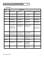
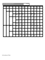
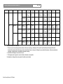
9.1.2 Functioning with parameters........................................................................................ 143
9.1.2.1 State definitions .............................................................................................. 143
9.1.2.2 Events definitions ........................................................................................... 144
9.1.2.3 Parameter definitions ..................................................................................... 144
9.1.2.4 Event / state matrix ......................................................................................... 144
9.2 Remote Functions ..................................................................................................................... 148
9.2.1 Introduction .................................................................................................................. 148
9.2.1.1 Remote function item explanation .................................................................. 148
9.2.2 Attendance/Access functions ...................................................................................... 148
9.2.2.1 AT_C_START_AT_APP................................................................................. 148
9.2.2.2 AT_C_STOP_AT_APP ................................................................................... 149
9.2.2.3 AT_C_STORE_SETTING .............................................................................. 149
9.2.2.4 AT_C_ACTIVATE ........................................................................................... 150
9.2.2.5 AT_C_HANDLE_IDENTIFICATION ............................................................... 151
9.2.2.6 AT_C_GET_INDIV_REGISTRATION ............................................................ 152
9.3 Update Notifications .................................................................................................................. 154
9.3.1 Introduction .................................................................................................................. 154
9.3.1.1 Preconditions .................................................................................................. 154
9.3.1.2 Notification item explanation........................................................................... 154
9.3.2 Attendance Registration and Access Control notifications .......................................... 155
9.3.2.1 AT_C_SEND_INDIV_REGISTRATION.......................................................... 155
9.3.2.2 AT_C_SEND_TOTAL_REGISTRATION ....................................................... 155
10. Text & Status Display for a Remote interface ................................................................................ 156
10.1 Introduction ............................................................................................................................. 156
10.1.1 Remote Text & Status Display Control ...................................................................... 156
10.2 Remote Functions ................................................................................................................... 156
10.2.1 Introduction ................................................................................................................ 156
10.2.1.1 Remote function item explanation ................................................................ 156
10.2.2 LD General functions ................................................................................................. 157
10.2.2.1 LD_C_START_LD_APP ............................................................................... 157
10.2.2.2 LD_C_STOP_LD_APP ................................................................................. 157
10.2.2.3 LD_C_STORE_DISPLAY_SETTING ........................................................... 158
10.2.2.4 LD_C_CLEAR_DISPLAY_NR ...................................................................... 159
10.3 Update Notifications ................................................................................................................ 160
10.3.1 Introduction ................................................................................................................ 160
10.3.1.1 Update notification item explanation............................................................. 160
10.3.1.2 Unit/user event relations ............................................................................... 161
10.3.2 LD General notifications ............................................................................................ 162
10.3.2.1 LD_C_SEND_ANUM_DATA ........................................................................ 162
11. Message Distribution for a Remote interface ................................................................................. 163
11.1 Introduction ............................................................................................................................. 163
11.1.1 Remote Message Distribution Control ....................................................................... 163
11.2 Remote Functions ................................................................................................................... 163
11.2.1 Introduction ................................................................................................................ 163
11.2.1.1 Remote function item explanation ................................................................ 163
11.2.2 Message Distribution functions .................................................................................. 164
11.2.2.1 MD_C_START_MON_MD ........................................................................... 164
11.2.2.2 MD_C_STOP_MON_MD ............................................................................. 164
11.2.2.3 MD_C_SEND_MESSAGE_TO_UNITS ........................................................ 165
11.2.2.4 MD_C_CLEAR_MESSAGE_ON_UNITS ..................................................... 166
11.2.2.5 MD_C_AUX_LED_CONTROL ..................................................................... 166
11.3 Update Notifications ................................................................................................................ 167
Bosch Security Systems | 2013 March
DCN Next Generation Open Interface Release 4.1
en | 8
11.3.1 Introduction ................................................................................................................ 167
11.3.1.1 Update notification item explanation............................................................. 167
11.3.1.2 Unit/user event relations ............................................................................... 167
11.3.2 MD General Notifications ........................................................................................... 168
11.3.2.1 MD_C_REQ_BUTTON_ON_OFF ................................................................ 168
12. Intercom for a Remote interface ...................................................................................................... 169
12.1 Introduction ............................................................................................................................. 169
12.1.1 Remote Intercom Control .......................................................................................... 169
12.2 Remote Functions ................................................................................................................... 169
12.2.1 Introduction ................................................................................................................ 169
12.2.1.1 Remote function item explanation ................................................................ 169
12.2.2 Intercom functions ..................................................................................................... 170
12.2.2.1 IC_C_START_IC_APP ................................................................................. 170
12.2.2.2 IC_C_CLOSE_IC_APP ................................................................................ 170
12.2.2.3 IC_C_SET_LINKS ........................................................................................ 171
12.2.2.4 IC_C_CLEAR_ LINKS .................................................................................. 171
12.3 Update Notifications ................................................................................................................ 171
12.3.1 Introduction ................................................................................................................ 171
12.3.1.1 Update notification item explanation............................................................. 171
12.3.1.2 Unit/user event relations ............................................................................... 172
12.3.2 Intercom notifications ................................................................................................. 172
12.3.2.1 IC_UPD_AVAILABLE_LINES ....................................................................... 172
12.3.2.2 IC_UPD_OPERATOR_STATE .................................................................... 172
12.3.2.3 IC_UPD_CONNECTION_INFO ................................................................... 173
12.3.2.4 IC_UPD_INCOMING_CALL ......................................................................... 173
Appendix A. Protocol, TCP/IP setting ................................................................................................... 174
A.1. TCP/IP port setting DCN-CCU ................................................................................................ 174
Appendix B. Values of the defines ........................................................................................................ 175
B.1. Defines sorted on application .................................................................................................. 175
B.2. Defines sorted on alphabet ...................................................................................................... 198
Appendix C. Error Codes ........................................................................................................................ 219
Appendix D. Examples ............................................................................................................................ 228
D.1. System Configuration .............................................................................................................. 228
D.1.1. Assigning seats using global installation .................................................................... 228
D.1.2. Replacing defective units during operation ................................................................ 229
D.2. Microphone Management ........................................................................................................ 230
D.2.1. Microphone Management Control .............................................................................. 230
D.3. Camera Control ....................................................................................................................... 232
D.3.1. Controlling CC application .......................................................................................... 232
D.4. Simultaneous Interpretation .................................................................................................... 234
D.4.1. Simultaneous Interpretation Control........................................................................... 234
D.5. Voting ...................................................................................................................................... 236
D.5.1. Running a vote round without update notifications .................................................... 237
D.6. Attendance Registration and Access Control .......................................................................... 240
D.6.1. Using Attendance Registration and Access Control .................................................. 240
D.7. Text & Status Display (LD) ...................................................................................................... 243
D.7.1. Controlling LD application .......................................................................................... 243
D.8. Message Distribution ............................................................................................................... 244
D.8.1. Sending a Message ................................................................................................... 245
D.9. Intercom .................................................................................................................................. 247
D.9.1. Intercom without update notifications ......................................................................... 247
Appendix E. Open interface changes in DcnNg 4.0 ............................................................................. 250
E.1. Changes with respect to DcnNg 3.1 ........................................................................................ 250
E.2. Changes with respect to DcnNg 2.68 ...................................................................................... 251
Bosch Security Systems | 2013 March
DCN Next Generation Open Interface Release 4.1
Bosch Security Systems | 2013 March
en | 9
DCN Next Generation Open Interface Release 4.1
en | 10
1. INTRODUCTION
1.1 Purpose
The purpose of this document is to describe the general remote interface (Open Interface)
aspects for any application to be remotely controlled on the CCU by third party software.
1.2 Scope
This document describes the remote interface. It is meant for developers who want to use this
remote interface to control applications present in the CCU.
The Open Interface must be licensed (LBB4187/00). Use the ‘Download and Licensing Tool’,
to enable the Open Interface. This tool is present on the DVD delivered the DCN conference
system.
1.3 Definitions, Acronyms and Abbreviations
ACK
ACN
ACS
ASCII
AT
AVS
CC
CCU
CR list
CS list
DB
DCC
DCN
DCN NG
DDI
FIFO
IC
IN
IP
DCN-CCU
LCD
LD
LED
LSB
MCCU
MD
Message-data
Message-type
MM
Bosch Security Systems | 2013 March
Acknowledge (of a packet)
Audio Communication Network
Access Control Services
American Standard for Character Information Interchange
Attendance Registration
Allegiant Video Switcher
Camera Control
Central Control Unit. This can be either a single-CCU system or a
Multi-CCU system.
Comment Request list. An extra type of request to speak list to offer
delegates the possibility to request for a comment on the current
speaker. On the units and on the Control PC a comment is indicated
as ‘Response’
Comment Speakers list. An extra type of speakers list in which
delegates can be placed to make a comment on the current speaker.
Delegate Database
Direct Camera Control
Digital Congress Network
Digital Congress Network Next Generation
Dual Delegate Interface
First In First Out
Intercom
Simultaneous Interpretation
Internet Protocol
Product number of the CCU. Which can be one of the following:
• DCN-CCU2
• DCN-CCUB2
Liquid Crystal Display
Text/Status Display
Light Emitting Diode
Least Significant Byte
Multi CCU system. A DCN NG system consisting of multiple slave
CCU’s and one master CCU
Message Distribution
Data transmitted along with a specific message-type. The data is
needed to fulfill the purpose of the message.
Specifies the purpose of the message (e.g. remote function call, etc.)
Microphone Management
en | 11
DCN Next Generation Open Interface Release 4.1
MSB
MTB
MV
NAK
Names file
NBK list
NG
NPPV
OMF File
PC
PCB
Present Key
PV
Remote Controller
RFS
RTS list
SC
SCCU
SI
SI
SI
SM
SPK list
ST
STP
TCB
TCP
UnitId
UnitId
UTP
VD
VT
Most Significant Byte
Multi Trunc Board
Multi Voting
Negative acknowledge (of a packet)
Permanent store for delegate data that are related, identifiable within
DCN NG
Notebook list (list of chairmen and special assigned delegates)
Next Generation
Ne Prennent pas Poart an Vote, delegate is present and does not
want to take part with the current voting round.
An executable file in a special format that can be programmed or
downloaded into the Read Only Memory on the CCU
Personal Computer
Printed Circuit Board
The leftmost softkey of the delegate or chairman unit (softkey 1) with
5 softkeys present, in case the settings and activation for attendance
registration request for that functionality
Parliamentary Voting
Device (e.g. PC) connected to the CCU that remotely controls one or
more of the applications present in the CCU.
Remote Function Services
Request To Speak list
System Configuration
Single-CCU system.
System Installation
System Installation
System Installation
Synoptic Microphone Control
Speakers list
Startup DCN Next Generation
Shielded Twisted Pair
Trunc Communication Board
Transmission Control Protocol
Unit identification, also called unit-number. A unique identification of
a unit within the CCU system.
Unit identification, also called unit-number. A unique identification of
a unit within the DCNNG system.
Unshielded Twisted Pair
Video Display
Voting application
CD
Rx
Tx
DTR
GND
DSR
RTS
CTS
RI
Definition RS-232 signals
Carrier Detect
Received Data
Transmitted Data
Data Terminal Ready
signal Ground
Data Set Ready
Request To Send
Clear To Send
Ring Indicator
CR
ESC
‘$’
‘?’
‘#’
‘@’
Definition ASCII characters used
Carriage Return ASCII character
Escape ASCII character
Dollar sign
Question mark
Number symbol
At character
Bosch Security Systems | 2013 March
(value 0x0D)
(value 0x1B)
(value 0x24)
(value 0x3F)
(value 0x23)
(value 0x40)
DCN Next Generation Open Interface Release 4.1
1.4 References
[USERDOC_CC]
[USERDOC_IC]
[USERDOC_IN]
[USERDOC_LD]
[USERDOC_MD]
Bosch Security Systems | 2013 March
User Manual Camera Control Application LBB 4188
User Manual Intercom Application LBB 4173
User Manual Simultaneous Interpretation Application LBB 4172
User Manual Text/Status Display LBB 4183
User Manual Message Distribution Application LBB 4182
en | 12
en | 13
DCN Next Generation Open Interface Release 4.1
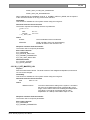
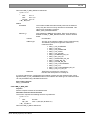
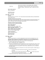
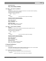
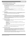
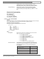
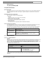
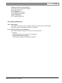
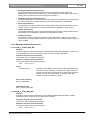
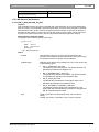
2. GENERAL DESCRIPTION
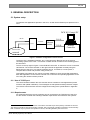
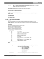
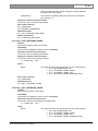
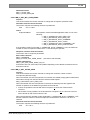
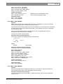
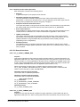
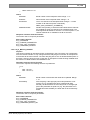
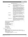
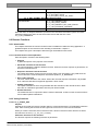
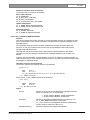
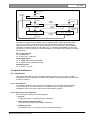
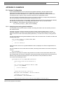
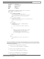
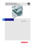
2.1 System setup
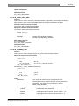
To interface with applications present in the CCU, we will use the Ethernet port present on the
CCU.
DCN NG Control PC
ACN
TCP/IP
TCP/IP
CCU
Ethernet
Switch
TCP/IP
Remote
Controller
DCN NG
network
Figure 1 Hardware configurations remote controls
The device (PC, embedded controller, etc.) connected to the Ethernet port is the second
1
controlling system to the CCU . This device is called remote controller in the remaining part of
the document.
The PC on the top-right in Figure 1 is the DCN NG control PC. A control PC can be connected
via Ethernet. The remote controller on the right controls an application remotely using the
Ethernet port of the CCU. This remote controller can be, for instance, a mimic panel, a
computer that controls and presents voting results, etc.
Third parties can build their own remote controller software to serve several SW-applications.
Each SW-application on the remote controller can control the corresponding application on the
CCU using the remote interface protocol.
2.1.1 Use of TCP/IP port
The communication between the CCU and the remote controller is message based (remote
functions and update notification). The messages are transported as binary streams of bytes.
The remote control interface must be configured according to the specifications in Appendix
A.
2.1.2 Requirements
As mentioned above the remote controller can be connected to the TCP/IP port of the CCU.
For the remote controller the following hardware requirements are needed for the systems:
1
We assume that the DCN NG Control PC connected to an Ethernet port is the primary controller for the CCU.
The remote controller is then the secondary controller. Only one remote controller is needed to control remotely.
Both controllers may be present and operate concurrent, controlling different parts of the CCU.
Bosch Security Systems | 2013 March
en | 14
DCN Next Generation Open Interface Release 4.1
⇒
Single/Multi CCU system (DCN-CCU):
This type of CCU has 1 TCP/IP port. An UTP or STP cable is used to connect the
master CCU-CCU to the remote controller.
The TCP/IP port number used for the communications is described in Appendix A.1.
2.1.3 Hardware connection
2.1.3.1 CCU
The hardware connection between the CCU and remote controller is made by using an UTP
or STP cable. The maximum cable length between the CCU and the remote controller may be
approximately 100 meter. When longer distances are needed we advise the use of a repeater
which ensures the transmission between two systems.
2.2 Message format
The communication used between the remote controller and the CCU is based on messages.
This chapter describes the format of the message and the different message types used to
transport data between the remote controller and the CCU.
2.2.1 Conventions
In the sections and chapters below several structures are defined. To prevent problems these
structures are defined using standard data types, which have defined sizes and usage. The
following data types will be used:
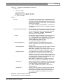
BOOLEAN : a 1 byte unsigned value with the range 0...1 (FALSE and TRUE).
CHAR
: a 1 byte type representing ASCII characters. Strings are represented as an
array of CHAR and are terminated with a zero (‘\0’) character.
BYTE
: a 1 byte unsigned value with the range 0...255.
SBYTE
: a 1 byte signed value with the range -128...127.
WORD
: a 2 byte unsigned value with the range 0...65535.
SWORD
: a 2 byte signed value with the range -32768...32767.
32
DWORD
: a 4 byte unsigned value with the range 0...(2 -1).
31
31
SDWORD : a 4 bytes signed value with the range -(2 )...(2 -1).
2
Note that all number representation in the data are presented in little-endian format.
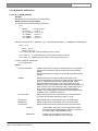
2.2.2 DCN-NG message layout
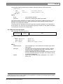
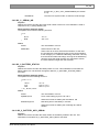
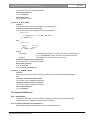
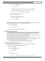
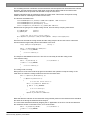
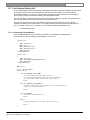
2.2.2.1 Format of type MDSC_REMOTEPROCEDURE_REQ
Remote functions are messages, which are always transmitted to the CCU. The message
type must be equal to the value ‘MDSC_REMOTEPROCEDURE_REQ’.
The “message data” transmitted for a remote function follows the following format:
typedef struct
{
WORD
wFnId;
// function identifier
REQSTRUC
tStructure; // function parameters if any!
} RSMT_REMOTEPROCEDURE_REQ;
where:
wFnId
The function identifier.
tStructure
A structure containing the parameters needed to process the
2
Little endian is a storage mechanism where the least significant byte is stored on the lowest address, followed
by the more significant bytes. E.g. a WORD is represented in memory as two consecutive bytes where the LSB
is stored on the lowest address and the MSB on the next address.
Bosch Security Systems | 2013 March
DCN Next Generation Open Interface Release 4.1
en | 15
function defined by the function identifier (if any).
The ‘wFnId’ and the ‘tStructure’ are tightly coupled. Therefore the parameter structure is not
defined strictly with the basic types, but a special type is used to identify that the structure
depends on the function identifier.
The actual structure definition to be sent along with the remote function is not described in this
document. The structures are presented along with the definition of the remote function in the
interface documents for the application.
After the remote function request is sent to the CCU, the CCU will always send back a
response upon the reception of a remote function (see §2.2.2.2). The remote controller should
wait for the response to be sure that the function ended successfully before sending another
remote function to the CCU.
Note that the CCU does not generate this kind of messages.
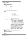
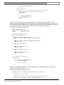
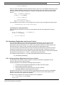
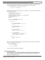
2.2.2.2 Format of type MDSC_REMOTEPROCEDURE_RSP
Upon a receipt of a remote function the CCU shall process the requested function and create
a response as result of that function. The message type will be equal to the value
‘MDSC_REMOTEPROCEDURE_RSP’.
The message data received for the response of a remote function follows the following format:
typedef struct
{
WORD
wFnId;
WORD
wError;
RSPSTRUC tStructure;
} RSMT_REMOTEPROCEDURE_RSP;
// function identifier
// return error-code from the function
// response information if any!
where:
wFnId
The function identifier. The same value as passed with the
remote function request.
wError
The return error-code of the function called. Note that if this
value is non-zero, the content of the ‘tStructure’ parameter is
3
not valid .
tStructure
A structure containing the response information after the
processing of the remote function (if any).
The ‘wFnId’ and the ‘tStructure’ are tightly coupled. Therefore the response information
structure is not defined strictly with the basic types, but a special type is used to identify that
the structure depends on the function identifier.
The actual structure definition to be received after handling a remote function request is not
described in this document. The structures are presented along with the definition of the
remote function in the interface documents for the application.
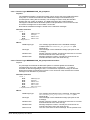
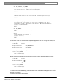
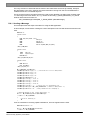
2.2.2.3 Format of type MDSC_NOTIFY
Upon a status change the CCU reports this change by sending an update notification to the
remote controller. It is up to the remote controller to use the information received from the
CCU. The CCU sends the information to the remote controller and does not expect any reply
from the remote controller on these notifications.
The update notifications are always coming from the CCU and are only sent to the remote
4
controller if he has registered for an application . The message type will be equal to the value
‘MDSC_NOTIFY’.
3
Upon error the ‘wError’ field is filled with an error code (see Appendix C), which references the source of the
error. Depending on the location of the error the ‘tStructure’ data may not be present. Therefore do not use the
‘tStructure’ data when ‘wError’ is not equal to zero.
When the error code has not been described, the error must be reported.
Bosch Security Systems | 2013 March
en | 16
DCN Next Generation Open Interface Release 4.1
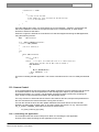
The message data received along the update notification follows the following format:
typedef struct
{
WORD
NTFSTRUC
} RSMT_NOTIFY;
wFnId;
tStructure;
// notification identifier
// update information if any!
where:
wFnId
The notification identifier.
tStructure
A structure containing the update information.
The ‘wFnId’ and the ‘tStructure’ are tightly coupled. Therefore the parameter structure is not
defined strictly with the basic types, but a special type is used to identify that the structure
depends on the notification identifier.
The actual structure definition to be sent along with the update notification is not described in
this document. The structures are presented along with the definition of the update notification
in the interface documents for the application.
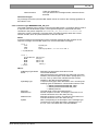
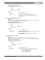
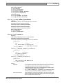
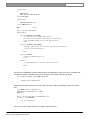
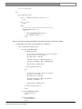
2.2.3 Ethernet message layout
Each message must have this layout:
MessageType
Length
Data
Defined in (c-style) structure format:
struct {
DWORD
DWORD
BYTE
};
dwMessageType;
dwLength;
byData[];
// Message Type
// Message Length
// Message Data (Length – 8 bytes)
Where:
dwMessageType
dwLength
byData
4
The “message-type”, which describes the content of the actual
data passed.
The total length of the message in number of bytes, including
the sizes of the message-type and length. The length must
match the actual transmitted size of bytes.
Since the MessageType and the Length are always present, the
minimum size of the message is 8 bytes. The maximum size of
a message is 8000 bytes.
Data here is the data described in paragraph 2.2.3.1, 2.2.3.2
and 2.2.3.3.
Registration for an application is done by calling a ‘start application’ remote function call. This function call
enables the transmission of update notification for that application. The update can be stopped again by calling
the ‘stop application’ remote function call.
Bosch Security Systems | 2013 March
DCN Next Generation Open Interface Release 4.1
en | 17
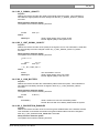
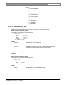
2.2.3.1 Format of type MESSAGETYPE_OIP_KeepAlive
Purpose:
The heartbeat message is a special message, which can be sent to the DCN NG System
at any time. In normal circumstances the heartbeat message is transmitted every 5
seconds (when nothing else to transmit). The message is used to notify the DCN NG
System that your system is still alive. The DCN NG System also sends heartbeat
messages to indicate that the DCN NG System is still operational. You must check if two
successive messages are received within 15 seconds.
Note that the heartbeat message is similar to the notification messages.
Parameter structure:
struct {
DWORD
DWORD
DWORD
DWORD
} OIP_KeepAlive;
dwMessageType;
dwLength;
dwReserved1;
dwReserved2;
Where:
dwMessageType
dwLength
dwReserved1
dwReserved2
The message type indicator for the heartbeat message.
Constant value MESSAGETYPE_OIP_KeepAlive (See
Appendix A).
The total length of the Heartbeat message (16 bytes for this
message).
Session sequence number. Currently the reserved1 is not used
and should be set to the value zero (0).
Message sequence number. Currently the reserved2 is not
used and should be set to the value zero (0).
2.2.3.2 Format of type MESSAGETYPE_OIP_ResponseProtocolError
Purpose:
Any message sent towards the DCN NG System is checked against its boundaries
(message size, string size, validity of the message-type, not logged in …). In case a
mismatch is detected regarding the size, a universal error response message is returned.
Response message as described in section 2.2.3.3 cannot be used, because the received
message is not decoded nor processed.
Parameter structure:
struct {
DWORD
dwMessageType;
DWORD
dwLength;
DWORD
dwReserved1;
DWORD
dwReserved2;
DWORD
dwErrorCode;
DWORD
dwErrorPosition;
} OIP_ResponseProtocolError;
Where:
dwMessageType
dwLength
dwReserved1
dwReserved2
dwErrorCode
Bosch Security Systems | 2013 March
The message type indicator for the message. Constant value
MESSAGETYPE_OIP_ResponseProtocolError (See
Appendix B).
The total length of the Heartbeat message (24 bytes for this
message).
Session sequence number. Currently the reserved1 is not used
and should be set to the value zero (0).
Message sequence number. Currently the reserved2 is not
used and should be set to the value zero (0).
The error code of the received message. For the possible error
DCN Next Generation Open Interface Release 4.1
en | 18
codes see Appendix C.
The byte offset in the message stream, where the fault is
detected.
dwErrorPosition
Related messages:
Any message received by the DCN NG System and is not conform the message guideline as
described in 2.2.3.
2.2.3.3 Format of type MESSAGETYPE_OIP_Dcn
Command messages can be sent to control the DCN NG System. Commands always result in
a response from the DCN NG System. The expected response is referenced with each
command or the generic response MESSAGETYPE_OIP_ResponseProtocolError is
returned in case the message is corrupted. Each command message starts with a fixed
number of fields, which are presented below in structure format.
NOTE:
In the time between the transmission of the command message and the reception of the
response message, the DCN NG System can receive notification messages.
struct {
BYTE
WORD
BYTE
} OIP_DCN_MSGTYPE
struct {
OIP_DCN_MSGTYPE
DWORD
DWORD
DWORD
BYTE
} OIP_Dcn;
byDcnMsgType;
wFnId;
byMessageTypeHeader; /* Fixed value 0x43 */
tMessageType;
dwLength;
dwReserved1;
dwReserved2;
byData[];
Where:
byMessageTypeHeader
wFnId
byDcnMsgType
dwLength
dwReserved1
dwReserved2
byData
Bosch Security Systems | 2013 March
Message type byte with a fixed value of 0x43.
The function identifier.
Note that the data in this message also starts with a function
identifier (see the description of the data in paragraph 2.2.2.1,
2.2.2.2, 2.2.2.3), this function identifier and the function
identifier in the data should be identical.
Is equal to the byType value described in 2.2.2. Currently the
following types are defined for communication with the CCU:
• MDSM_REMOTEPROCEDURE_REQ
• MDSM_REMOTEPROCEDURE_RSP
• MDSM_NOTIFY
The total length of the command structure.
Session sequence number. Currently the reserved1 is not
used and should be set to the value zero (0)
Message sequence number. Currently the reserved2 is not
used and should be set to the value zero (0).
Data corresponding to the description of the message-type.
The data here is the data described in paragraph 2.2.2.1,
2.2.2.2, 2.2.2.3 and starts with a function identifier.
en | 19
DCN Next Generation Open Interface Release 4.1
2.3 Protocol description
2.3.1 Ethernet Protocol Description
2.3.1.1 Open interface protocol
2.3.1.1.1 Set-up a connection
After DCN NG has been started, the CCU listens to port 9451. The set-up of the TCP/IP
connection must originate from your system using the IP address of the CCU and port 9451.
The connection between the DCN NG System and your System is based on a stream
connection. This implies that messages may be transferred using multiple packets.
2.3.1.1.2 Heartbeat
After the connection between your system and DCN NG has been established, the CCU of
DCN NG starts the heartbeat checks of your system. The CCU checks if a message is
received within 15 seconds after the last message. When the time between two messages is
more than 15 seconds, the CCU considers the connection to be broken and closes the
TCP/IP connection to your system.
It is advised to also run heartbeat checks of DCN NG on your system. To signal that the
connection is still present, you must transmit a "MESSAGETYPE_OIP_KeepAlive" message
(refer to section 2.2.3.1) to the CCU every 5 seconds when no other messages are ready for
transmission.
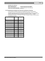
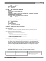
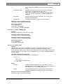
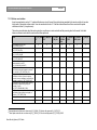
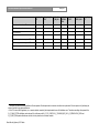
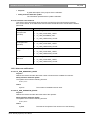
2.3.1.1.3 Timing values
This section presents the different value and time-limits needed for handling the protocol.
Description
Value
Transmit timeout for transmission heartbeat message
Check timeout to verify whether a message is received (reset after each
message reception)
Maximum command response time
Minimum message size (message-type + length)
Maximum message size
5 seconds
15 seconds
10 seconds
8 bytes
8000 bytes
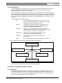
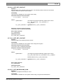
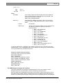
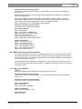
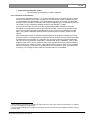
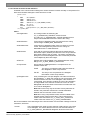
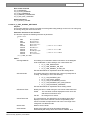
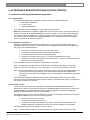
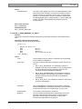
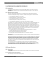
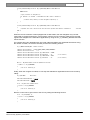
2.3.2 Remote function execution
Beside the protocol used for transmitting the data between the remote controller and the CCU,
the CCU executes the remote function requests. In this section the execution of the remote
functions is explained to give an overview about the generation of updates during the
execution.
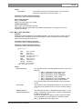
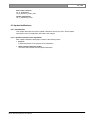
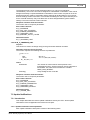
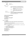
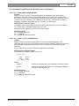
The remote controller can sent a remote function request to the CCU. After the transmission
the remote controller must wait for the response coming from the CCU.
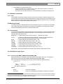
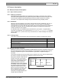
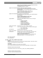
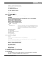
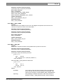
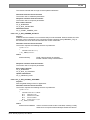
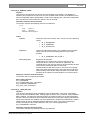
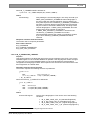
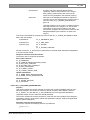
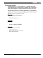
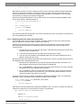
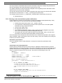
During the execution of that remote
function in the CCU, the internal
state of e.g. microphones changes.
This results in the generation of
update notifications, which are
transmitted to the remote controller
immediately. After the completion of
the remote function execution the
response of that function is sent
back to the remote controller. This
flow of messages to and from the
CCU is shown in Figure 2 (two
notification messages between the
request and the response).
Bosch Security Systems | 2013 March
Remote Controller
Request
Notify
Notify
Response
CCU
time
Figure 2 Message flow during a Remote function
DCN Next Generation Open Interface Release 4.1
en | 20
The typical time between the request made and the response received is less than 0,5
seconds.
In the sequence described there is only one remote function request in execution on the CCU.
The remote controller waits for the completion of that remote function. The remote controller
can expect the following ending states of the remote request:
• The actual response of the remote function. The remote function is ended and there were
no transmission errors.
• The NAK packet. This implies that the CCU had a checksum error found after the
reception of the remote function request. The remote controller should respond on this
NAK message by sending again the same request.
• A time-out of the request pending. This means that the CCU does not respond any more.
The remote controller must wait upon the completion of his remote function request. But in
rare circumstance it is possible that there are two remote function requests pending. In that
case the CCU handles both remote function requests after each other (order is maintained).
2.3.3 Control flow with multiple remote controller’s
In a DCN NG-system as shown in Figure 1 (CCU with both a remote controller and the DCN
NG Control PC connected), there are up to three locations where events can be generated.
The locations are:
• The actual units. E.g. microphone keys, soft-keys (voting).
• The DCN NG Control PC connected using Ethernet. This DCN NG Control PC uses
Remote Function calls to trigger functionality.
• The remote controller connected using Ethernet. This Remote Controller also uses
Remote Function calls to trigger functionality.
To get a fully operational system both the DCN NG Control PC and the remote controller must
register themselves to the CCU, so they will receive update messages from the CCU.
Events coming from a unit are processed. During the processing, notifications are generated
and sent to all registered controllers. In the system mentioned above, both the DCN NG
Control PC and the Remote Controller will receive the same update notifications if they are
registered to the same application.
Remote functions coming from either the DCN NG Control PC or the Remote Controller
initiate a function in the CCU. During the function processing, notifications are generated and
sent to both the DCN NG Control PC and the Remote Controller. In this way both remote
controllers get the update information about the actions performed on request of the DCN NG
Control PC or the Remote Controller. (see also Figure 2).
Note that all remote functions are stored in a FIFO queue before execution. This means that
when both controllers call a remote function, both remote functions will be executed one after
another (the time difference depends which function will be executed first).
2.4 Remote Functions
2.4.1 Remote function handling
On the CCU all incoming remote functions are handled by the Remote Function Services
(RFS). During start-up of the system applications register their remote controllable functions at
the Remote Function Services.
When a remote function request is received by the CCU, that request is passed to the RFS
sublink. If the function is available, the data structure will be prepared for the response data.
During this process general failures may occur. The RFS sublink handles these failures by
returning an empty response (only containing the function identifier and the error-code, no
extra data). The error-code informs the remote controller which general failure has occurred.
Bosch Security Systems | 2013 March
DCN Next Generation Open Interface Release 4.1
Possible error codes are:
RFSE_BADFUNCTIONID
The remote function is not available
RFSE_ALLOCFAILED
Response space allocation failure
RFSE_NOACCESSPERMISSION The remote function is not authorized
These error-codes are described in Appendix C.
2.4.2 Simultaneous operation from Control PC and Remote Controller
In some cases it is possible to have the same application running on the DCN Next
Generation Control PC and (simultaneously) having that application running on a remote
controller. Some applications can only be active on one place at a time. In the table below all
possible combinations are depicted. All legal combinations are marked +. All illegal
combinations are marked -. If an illegal combination is created, the proper working of DCN is
not guaranteed anymore.
Remote Interface apps
DCN-SW
DCN-SWSMV
SI
-
-
DB
-
-
SC
+
+
MM
+
+
CC
-
+
IN Control
-
+
IN Monitoring
+
+
VT
-
-
LD
-
-
MD
+
+
AT
-
+
IC Control
-
-
IC Monitoring
+
+
Bosch Security Systems | 2013 March
en | 21
DCN Next Generation Open Interface Release 4.1
en | 22
3. SYSTEM CONFIGURATION AND SYSTEM INSTALLTION
3.1 Introduction
The System Configuration and System Installation Remote Interface is part of the DCN NG
software which allows another controlling entity, not being the DCN NG Control PC, to use the
System Configuration and System Installation.
3.1.1 Remote functions
System Configuration (SC) is the application that monitors the hardware configuration of the
congress system and the link between hardware items and user information. Typical SC
issues are, e.g. checking the communication status, determining the system mode and
replacing units.
System Installation (SI) is the application that allows for assigning seat numbers to units to
create a one to one link between a unique user chosen identifier and a congress unit in the
conference hall.
Maintaining the system configuration or performing a system installation with a remote
interface is done by means of calling a defined set of Remote Functions and acting upon a
defined set of Update Notifications. The general concept of remote functions and update
notifications is described in chapter 2. This chapter also defines the protocol and hardware
conditions concerning the remote interface. This document gives the set of remote functions
and the set of update notifications concerning SC and SI. The relation between remote
function and update notifications is given in the description of each separate remote function.
The system configuration and system installation process however, are also influenced by the
actions of the users performed upon the actual units. Actions such as pressing the
microphone button or disconnecting a unit from the system also results in update notifications
being sent to the remote controller. The relation between unit/user events and update
notifications can be found in the user event matrices in sections 3.4.1.2 en 3.6.1.1.
3.1.1.1 Remote function item explanation
Each description consists of the following items:
• Purpose
A global description of the purpose of the function.
• Availability
CCU System modes in which the function is available. See section 3.1.2.
• Parameter structure for the function
The input parameters needed to fulfill the function. When the function requires no
parameters, no structure is described here.
• Response structure from the function
The output information returned by the function called. This information is only valid when
the ‘wError’ field of the received response information equals SC_E_NOERROR,
SI_E_NOERROR or DB_E_NOERROR.
• Error codes returned
The error values returned in the ‘wError’ field of the response information. All different error
codes are described in Appendix C Error Codes.
• Update notifications
The update notifications, which are generated during the execution of the remote function.
When there are no notifications generated, then this part will be omitted.
Related functions
The related function in conjunction with the function described. It refers to other remote
functions and to related update notifications.
Bosch Security Systems | 2013 March
en | 23
DCN Next Generation Open Interface Release 4.1
3.1.2 System Modes
To understand the SC and SI functions, one should have some knowledge on the behavior of
the CCU depending on the various so-called system modes. This section gives a brief,
although complete, description of these modes.
The CCU system as a whole is always running in one of the system modes. Each application
on the CCU has its own behavior in each system mode. The purpose of the system mode is to
have a clear division of functions and an easy way of separating them. It should be impossible
for instance to start the installation mode while the CCU is still booting, i.e. the CCU is in the
Init-mode.
The following system modes are used:
Init
One time mode after start-up of the CCU. The CCU can
start with default data (defined as ‘cold start’), or with data
the last time used (so called ‘warm start’).
Config
In this system mode the DCN NG configuration can be
changed, for instance installing units, assigning seat
numbers, assigning audio channels etc.
Congress
This is the 'normal' system mode. In this mode most
applications will do their work, for instance starting a voting
round, turning on a microphone, interpreting etc.
Maintenance
In this system mode the DCN NG system can be
maintained, for instance factory testing.
Download
In this system mode new CCU software can be
downloaded.
Down
One time system mode just before shutdown of the CCU.
Figure 3 below gives an overview of possible system mode changes.
Init
Config
Congress
Download
Maintenance
Down
Figure 3: CCU System modes
Per function is specificated what system modes are supported.
3.2 System Configuration (SC) Functions
3.3 Introduction
The system configuration functions described in this section are needed to query the set-up of
the DCN NG-system from the CCU. The system configuration functions allow the remote
controller to monitor any changes in the DCN NG system configuration. This chapter defines
the set of remote functions for system configuration.
Bosch Security Systems | 2013 March
DCN Next Generation Open Interface Release 4.1
en | 24
3.3.1 SC_C_CHECK_LINK
Purpose
Function, which does no execution on the CCU. This function is to check the communication
link between the CCU and the remote controller. When executed, the function returns
immediately. Therefore quickly returning SC_E_NOERROR to the remote controller when
there is a connection.
Availability
This function is available in CCU system mode's init, maintenance, config and congress.
Parameter structure for the function
The function has no additional parameters.
Response structure from the function
The function has no response parameters.
Error codes
SC_E_NOERROR
3.3.2 SC_C_START_APP
Purpose
Indicates the CCU that the remote controller wants update notifications from the SC
application inside the CCU. After receiving this function the CCU increments the update ‘use’
count. As long as the update use count is greater than zero, the CCU will send update
notifications to the remote controller.
The returned update use count can be used to detect if the remote controller is connected too
often.
When you omit the execution of this remote function, you can still execute remote functions,
but no update messages will be sent to the remote controller.
Availability
This function is available in CCU system modes config and congress.
Parameter structure for the function
The function has no additional parameters.
Response structure from the function
The function returns the following structure:
WORD
wNrOfInstances
where:
wNrOfInstances
The value of the update use count for the SC application at the
end of the function handling. It contains the number of times a
remote PC has been connected over the same communication
medium. E.g. the first time the function SC_C_START_APP is
called, it contains the value 1.
Error codes returned
SC_E_NOERROR
Related functions
SC_C_STOP_APP
3.3.3 SC_C_STOP_APP
Purpose
Indicates the CCU that the remote controller no longer requires updates from the SC
application inside the CCU. After receiving this function the CCU decrements the update ‘use’
count. As long as the update use count is greater than zero, the CCU remains sending the
update notifications to the remote controller.
Bosch Security Systems | 2013 March
DCN Next Generation Open Interface Release 4.1
Note that:
en | 25
Upon communication loss this function will be activated, if
SC_C_START_APP was activated. The activation of this function is repeated
till the update use count becomes zero.
Availability
This function is available in CCU system modes config and congress.
Parameter structure for the function
The function has no additional parameters.
Response structure from the function
The function has the same response structure as the remote function SC_C_START_APP
(section 3.3.2).
Error codes returned
SC_E_NOERROR
Related functions
SC_C_START_APP
3.3.4 SC_C_GET_CCU_VERSIONINFO
Purpose
This function is used to query the CCU version information. Usually this will be the first
function called after start-up of the remote controller to check the correct version of the CCU
software.
Availability
This function is available in all CCU system modes.
Parameter structure for the function
The function has no additional parameters.
Response structure from the function
The function returns the following structure:
typedef struct
{
WORD
CHAR
BYTE
BYTE
BYTE
BYTE
BYTE
BYTE
WORD
BYTE
BYTE
CHAR
} SC_T_CCU_VERSION_INFO;
tOperatingMode;
szSwVersion [SC_C_MAX_VERSION_LENGTH];
byMajorVersionOfDownloadedSw;
byMinorVersionOfDownloadedSw;
byMajorVersionOfResidentSw;
byMinorVersionOfResidentSw;
bySystemMode;
byReservedForSwInfo [SC_C_MAX_SOFTWARE_INFO];
tCCUType;
byTCBVersion;
byReservedForHwInfo [SC_C_MAX_HARDWARE_INFO];
szSWRelNum[VERSION_C_LENGTH];
where:
tOperatingMode
The current operating mode of the CCU. It gives information
about the environment the CCU is functioning. The value is an
‘OR’ mask of the following settings:
• SC_C_STANDALONE
• SC_C_EXTENDED
• SC_C_SINGLETRUNC
• SC_C_MULTITRUNC
• SC_C_MASTER
• SC_C_SLAVE
szSwVersion
The current operating mode of the CCU in readable text. The
Bosch Security Systems | 2013 March
DCN Next Generation Open Interface Release 4.1
en | 26
string is zero (‘\0’) terminated. If e.g. it is a Single CCU running
extended software, this string would read:
“EXTENDED SingleTrunc Version”.
byMajorVersionOfDownloadedSw, byMinorVersionOfDownloadedSw
The major and minor version numbers of the downloaded
software (OMF-file). If no downloaded software is present, then
both will be zero.
If e.g. the downloaded software is DCN NG 4.0,
byMajorVersionOfDownloadedSw will be ‘4’ and
byMinorVersionOfDownloadedSw will be ‘0’
byMajorVersionOfResidentSw, byMinorVersionOfResidentSw
The major and minor version numbers of the resident software
(Boot-software).
If e.g. the resident software is of version 1.0,
byMajorVersionOfResidentSw will be ‘1’ and
byMinorVersionOfResidentSw will be ‘0’.
bySystemMode
The Current System Mode of the CCU. Value according to
following type:
• DCNC_SM_DOWN
• DCNC_SM_INIT
• DCNC_SM_CONFIG
• DCNC_SM_CONGRESS
• DCNC_SM_MAINTENANCE
• DCNC_SM_DOWNLOAD
byReservedForSwInfo
Reserved space for extra software information.
tCCUType
byTCBVersion
Type of CCU connected to. Value according to following type:
• SC_C_DCN_CCU2
• SC_C_DCN_CCUB2
Hardware version of the CCU.
byReservedForHwInfo
Reserved space for extra hardware information.
szSWRelNum
Software version number as ASCII string. The string is zero
(‘\0’) terminated. This is the string representation of
byMajorVersionOfDownloadedSw plus
byMinorVersionOfDownloadedSw, e.g. if the version of the
downloaded software is 4.0, this string will read “4.0”
Error codes returned
SC_E_NOERROR
3.3.5 SC_C_GET_CCU_CONFIG <deprecated>
Purpose
Retrieve information about all units connected to the congress network. This function returns
for each unit connected its unit-number and type.
Availability
This function is available in CCU system mode congress.
Do not use this function because this function becomes deprecated in next major release.
Parameter structure for the function
The parameter structure is the same as SC_C_GET_CCU_CONFIG_PROPERTY.
Response structure from the function
The function returns the following structure:
Bosch Security Systems | 2013 March
DCN Next Generation Open Interface Release 4.1
en | 27
typedef struct
{
WORD
wNumberOfSlaveCCUs;
WORD
wNumberOfUnitsConnected;
WORD
wNumberOfUnits;
SC_T_UNIT_DATA tUnitData [SC_C_CLUSTER_MAX];
} SC_T_CCU_CONFIGURATION;
where the SC_T_UNIT_DATA is defined as:
typedef struct
{
WORD
wUnitId;
BYTE
byUnitType;
} SC_T_UNIT_DATA;
The respons structure is almost the same as SC_C_GET_CCU_CONFIG_PROPERTY with
the exception of the SC_T_UNIT_DATA structure which does not contain the wUnitProperties
which is available in SC_T_UNIT_DATA_PROPERTY.
For explanation of the parameters see SC_C_GET_CCU_CONFIG_PROPERTY.
Error codes returned
SC_E_NOERROR
3.3.6 SC_C_GET_CCU_CONFIG_PROPERTY
Purpose
Retrieve information about all units connected to the congress network. This function returns
for each unit connected its unit-number, type and capabilities of the unit.
Availability
This function is available in CCU system mode congress.
Parameter structure for the function
The function requires the following structure as parameter:
WORD
wClusterIndex;
where:
wClusterIndex
Determines which cluster is to be returned as response. Zero
(0) to retrieve the first cluster of SC_C_CLUSTER_MAX units.
One (1) for the second cluster of SC_C_CLUSTER_MAX units,
etc.
When the cluster is not completely filled, then that cluster is the
last cluster available.
All cluster indexes greater than this one will have an empty
tUnitData array. However, the other three elements of the
response structure will still contain correct data.
Response structure from the function
The function returns the following structure:
typedef struct
{
WORD
wNumberOfSlaveCCUs;
WORD
wNumberOfUnitsConnected;
WORD
wNumberOfUnits;
SC_T_UNIT_DATA_PROPERTY tUnitData [SC_C_CLUSTER_MAX];
} SC_T_CCU_CONFIGURATION;
where the SC_T_UNIT_DATA_PROPERTY is defined as:
Bosch Security Systems | 2013 March
en | 28
DCN Next Generation Open Interface Release 4.1
typedef struct
{
WORD
wUnitId;
BYTE
byUnitType;
WORD
wUnitProperties
} SC_T_UNIT_DATA_PROPERTY;
where:
wNumberOfSlaveCCUs
The number of Slave-CCU’s connected within a Multi-CCU
system, which ranges from 0 to 16. In case of a Single-CCU
system this number will be zero.
wNumberOfUnitsConnected
The actual number of units present in the system, even if the
total number is larger than the maximum size of the ‘tUnitData’
array. wNumberOfUnitsConnected ranges from 0 to
DBSC_MAX_ACT_UNIT.
When there are more units than the size of the ‘tUnitData’
structure, the structure is completely filled and the unit data for
the other units must be queried by using another clusterindex.
This number will be the same for all clusters requested.
wNumberOfUnits
The number of units present in the tUnitData array. Only this
amount of array elements is transmitted. This number will be
limited to the upper bound of the tUnitData array-size.
tUnitData []
Array holding the unit-information of each unit. Each array
element is defined as a SC_T_UNIT_DATA structure. The
elements of this structure are described below.
wUnitId
The unit identifier of a unit. Also called unit-number.
byUnitType
The type of the unit, which is on of the following:
• DCNC_UNIT_VOTING
• DCNC_UNIT_INTEGRUS4
• DCNC_UNIT_INTEGRUS8
• DCNC_UNIT_INTEGRUS16
• DCNC_UNIT_INTEGRUS32
• DCNC_UNIT_DATA_COMM
• DCNC_UNIT_NG_INTERPRETER
• DCNC_UNIT_CCU_CONTROL
• DCNC_UNIT_DATA_COMM_RS232
• DCNC_UNIT_2000_DELEGATE
• DCNC_UNIT_2000_CHAIRMAN
•
•
•
•
•
•
•
•
•
•
•
•
DCNC_UNIT_AUDIO_IO
DCNC_UNIT_AUDIO_IO_DIGITAL
DCNC_UNIT_COBRANET
DCNC_UNIT_DISC_DELEGATE
DCNC_UNIT_DISC_DELEGATE_DUAL
DCNC_UNIT_DISC_CHAIRMAN
DCNC_UNIT_DUAL_MIC
DCNC_UNIT_FLUSH_CHR_NODISPLAY
DCNC_UNIT_FLUSH_DEL_NODISPLAY
DCNC_UNIT_ENTRANCE
DCNC_UNIT_EXIT
DCNC_UNIT_AMBIENT_MIC
Note that future unit extensions of the DCN NG system
can lead to new unit-type, not presented in this list.
Bosch Security Systems | 2013 March
en | 29
DCN Next Generation Open Interface Release 4.1
.
wUnitProperties
Holds the properties of a unit. This can be a
combination of the following.
DCNC_HAS_MIC
DCNC_HAS_AUX
DCNC_HAS_KEYS
DCNC_HAS_CARD
DCNC_HAS_DISPLAY
DCNC_HAS_GRAPHICAL_DISPLAY
DCNC_HAS_INTERCOM
DCNC_HAS_EXTERNAL
DCNC_HAS_BOOTH_DESK
DCNC_HAS_HELP
DCNC_HAS_SPEAKSLOWLY
DCNC_HAS_BATTERY
DCNC_HAS_QUALITY_LEVEL
DCNC_HAS_DATACHANNEL_SUPPORT
DCNC_HAS_MOST_INTERFACE
DCNC_HAS_NEED_FOR_CARD_SETTINGS
Error codes returned
SC_E_NOERROR
3.3.7 SC_C_REQ_SERIAL_NR
Purpose
Request the serial numbers of the specified units of the system. The master controller will
return the serial numbers with the SC_C_SERIAL_NR notification.
Availability
This function is available in system mode: MAINTENANCE, CONFIG and CONGRESS.
Parameter structure for the function
The function requires the following structure as parameter:
typedef struct
{
WORD
UNITID
} SC_T_UNIT_LIST;
wNrOfUnits;
tUnitId[DBSC_MAX_ACT_UNIT];
where:
wNrOfUnits
The number of unit list entries actual present in the tUnitId
array. Only this amount of array elements is transmitted. This
value never exceeds the constant DBSC_MAX_ACT_UNIT.
tUnitId []
Array holding the list of unit ids.
UnitId 0x0000 will return the serial number of the master
controller.
Response structure from the function
The function has no response parameters.
Error codes returned
SC_E_NOERROR
SC_E_WRONG_PARAMETER
Update notifications
SC_C_ SERIAL_NR
3.3.8 SC_C_GET_SLAVE_NODES
Purpose
Retrieve the slave nodes of a unit with the specified serial number. The serial number can only
be from the current master controller (CCU) or any slave CCU or WAP. The current master
controller returns a list of all serial numbers of all the directly attached units.
Bosch Security Systems | 2013 March
DCN Next Generation Open Interface Release 4.1
en | 30
Availability
This function is available in system mode: MAINTENANCE, CONFIG and CONGRESS.
Parameter structure for the function
DWORD
dwSerialNr;
where:
dwSerialNr
The serial number of a unit of CCU type.
Response structure from the function
The function returns the following structure:
typedef struct
{
WORD
DWORD
} SC_T_SERIAL_NR_LIST;
wNrOfSerialNrs;
dwSerialNr[DBSC_MAX_ACT_UNIT];
where:
wNrOfSerialNrs
The number of slave nodes present in the dwSerialNr array. Only
this amount of array elements is transmitted. This number will be
limited to the upper bound of the dwSerialNr array-size.
dwSerialNr []
Array holding the serial number of each slave node.
Error codes returned
SC_E_NOERROR
SC_E_WRONG_PARAMETER
SC_E_UNIT_NOT_FOUND
Related functions
SC_C_REQ_SERIAL_NR
3.3.9 SC_C_GET_ UNIT_IDS
Purpose
Retrieve the unit identification(s) of the unit with the specified serial number. A unit can have
one or more unit identifications.
Availability
This function is available in system mode: MAINTENANCE, CONFIG and CONGRESS.
Parameter structure for the function
DWORD
dwSerialNr;
where:
dwSerialNr
The serial number of a unit
Response structure from the function
typedef struct
{
WORD
UNITID
} SC_T_UNIT_LIST;
wNrOfUnits;
tUnitId[DBSC_MAX_ACT_UNIT];
where:
wNrOfUnits
The number of unit list entries actual present in the tUnitId
array. Only this amount of array elements is transmitted. This
value never exceeds the constant DBSC_MAX_ACT_UNIT.
tUnitId []
Array holding the list of unit ids.
Error codes returned
SC_E_NOERROR
SC_E_WRONG_PARAMETER
SC_E_UNIT_NOT_FOUND
Bosch Security Systems | 2013 March
DCN Next Generation Open Interface Release 4.1
Related functions
SC_C_REQ_SERIAL_NR
3.3.10 SC_C _BATTERY_STATUS_REQ
Purpose
This function will request the battery status of all units in the parameter list. After executing
this function a notification will be send for each known unit.
Availability
This function is available in system mode: MAINTENANCE, CONFIG and CONGRESS.
Parameter structure for the function
The function requires the following structure as parameter:
typedef struct
{
WORD
wNrOfUnits;
UNITID
tUnitList[DBSC_MAX_UNIT];
} SC_T_UNIT_LIST;
where:
wNrOfUnits
The number of unit list entries actual present in the tUnitList
array. Only this amount of array elements is transmitted. This
value never exceeds the constant DBSC_MAX_UNIT.
tUnitList[]
Array holding the list of unit ids.
Response structure from the function
The function has no response parameters.
Error codes returned
SC_E_NOERROR
SC_E_UNIT_NOT_CONNECTED
SC_E_UNIT_NOT_FOUND
Update notifications
SC_C_BATTERY_STATUS
3.3.11 SC_C_BATTERY_INFO_REQ
Purpose
This function will request the battery information of all units in the parameter list. After
executing this function two notifications will be send for each known unit.
Availability
This function is available in system mode: MAINTENANCE, CONFIG and CONGRESS.
Parameter structure for the function
The function requires the following structure as parameter:
typedef struct
{
WORD
wNrOfUnits;
UNITID
tUnitList[DBSC_MAX_UNIT];
} SC_T_UNIT_LIST;
where:
wNrOfUnits
The number of unit list entries actual present in the tUnitList
array. Only this amount of array elements is transmitted. This
value never exceeds the constant DBSC_MAX_UNIT.
tUnitList[]
Array holding the list of unit ids.
Bosch Security Systems | 2013 March
en | 31
DCN Next Generation Open Interface Release 4.1
en | 32
Response structure from the function
The function has no response parameters.
Error codes returned
SC_E_NOERROR
SC_E_UNIT_NOT_CONNECTED
SC_E_UNIT_NOT_FOUND
Update notifications
SC_C_BATTERY_SERIAL
SC_C_BATTERY_ COND
3.3.12 SC_C_SIGNAL_STATUS_REQ
Purpose
This function will request the signal status of all units in the parameter list. After executing this
function a notification will be send for each known unit.
Availability
This function is available in system mode: MAINTENANCE, CONFIG and CONGRESS.
Parameter structure for the function
The function requires the following structure as parameter:
typedef struct
{
WORD
wNrOfUnits;
UNITID
tUnitList[DBSC_MAX_UNIT];
} SC_T_UNIT_LIST;
where:
wNrOfUnits
The number of unit list entries actual present in the tUnitList
array. Only this amount of array elements is transmitted. This
value never exceeds the constant DBSC_MAX_UNIT.
tUnitList[]
Array holding the list of unit ids.
Response structure from the function
The function has no response parameters.
Error codes returned
SC_E_NOERROR
SC_E_UNIT_NOT_CONNECTED
SC_E_UNIT_NOT_FOUND
Update notifications
SC_C_SIGNAL_STATUS
3.3.13 SC_C_SIGNAL_QUALITY_REQ
Purpose
This function will request the signal quality of the system.
Availability
This function is available in system mode: MAINTENANCE, CONFIG and CONGRESS.
Parameter structure for the function
The function has no additional parameters.
Response structure from the function
The function has no response parameters.
Error codes returned
SC_E_NOERROR
Update notifications
SC_C_ SIGNAL_QUALITY
Bosch Security Systems | 2013 March
DCN Next Generation Open Interface Release 4.1
en | 33
3.3.14 SC_C_UNIT_SIGNAL_QUALITY_REQ
Purpose
This function will request the signal quality of all units in the parameter list. After executing this
function a notification will be send for each known unit.
Availability
This function is available in system mode: MAINTENANCE, CONFIG and CONGRESS.
Parameter structure for the function
The function requires the following structure as parameter:
typedef struct
{
WORD
wNrOfUnits;
UNITID
tUnitList[DBSC_MAX_UNIT];
} SC_T_UNIT_LIST;
where:
wNrOfUnits
The number of unit list entries actual present in the tUnitList
array. Only this amount of array elements is transmitted. This
value never exceeds the constant DBSC_MAX_UNIT.
tUnitList[]
Array holding the list of unit ids.
Response structure from the function
The function has no response parameters.
Error codes returned
SC_E_NOERROR
Update notifications
SC_C_UNIT_SIGNAL_QUALITY
3.3.15 SC_C_LOW_BATTERY_REQ
Purpose
This function will request the global low battery status of the system.
Availability
This function is available in system mode: MAINTENANCE, CONFIG and CONGRESS.
Parameter structure for the function
The function has no additional parameters.
Response structure from the function
The function has no response parameters.
Error codes returned
SC_E_NOERROR
Update notifications
SC_C_ LOW_BATTERY
3.3.16 SC_C_GET_ENCRYPTION_ENABLED
Purpose
Retrieve the current encryption enabled status.
Availability
This function is available in system mode: MAINTENANCE, CONFIG and CONGRESS.
Parameter structure for the function
The function has no additional parameters.
Response structure from the function
The function returns the following structure:
Bosch Security Systems | 2013 March
en | 34
DCN Next Generation Open Interface Release 4.1
BOOLEAN
bEnabled;
Error codes returned
SC_E_NOERROR
3.3.17 SC_C_SET_ENCRYPTION_ENABLED
Purpose
Set the current encryption enabled status.
Availability
This function is available in system mode: MAINTENANCE, CONFIG and CONGRESS.
Parameter structure for the function
The function requires the following structure as parameter:
BOOLEAN
bEnabled;
Response structure from the function
The function has no response parameters.
Error codes returned
SC_E_NOERROR
SC_E_INVALID_CHANNEL
SE_E_FAILED
Update notifications
SC_C_ ENCRYPTION_ENABLED
3.4 System Configuration (SC) notifications
3.4.1 Introduction
This chapter defines the set of update notifications concerning SC send by the CCU.
3.4.1.1 Update Notification item explanation
Each description consists of the following items:
• Purpose
A global description of the purpose of the notification.
• Notify structure with this update
The information passed with the update notification.
3.4.1.2 Unit/user event relations
In the previous chapter a description is given of each remote function with a summary of
update notifications being the result of executing that function. However, update notifications
are also the results of user actions done on the actual units or CCU’s. This section gives
unit/user event matrices for the SC application in which the possible user events are linked
with the corresponding update notification(s) depending on the system set-up. For some
events also the required remote functions to continue SC monitoring and maintaining are
given.
The update notifications themselves are described in the remaining sections of this chapter.
The recommended functions from the SI group are described in chapter 3.4.8.
UNIT-EVENT MATRIX
Single-CCU System (Remote Controller connected as specified in chapter 2
Event
Update Notification
Continue with remote function
Switch On CCU
SC_C_CCU_REBOOT
SC_C_START_APP
Recommended before continuing:
SC_C_GET_CCU_VERSIONINFO
Bosch Security Systems | 2013 March
en | 35
DCN Next Generation Open Interface Release 4.1
Event
Update Notification
Continue with remote function
SC_C_GET_CCU_CONFIG
SI_C_START_INSTALL and run
installation as described in example-1
in Appendix D
Connect a unit
SC_C_CONNECT_UNIT
Disconnect a unit
SC_C_DISCONNECT_UNIT
Recommended before continuing:
SI_C_START_INSTALL and run
installation as described in example-2
in Appendix D
Multi-CCU System (Remote Controller connected to the Master as specified in chapter 2
Event
Update Notification
Switch On a Slave CCU,
while Master CCU is still
off
<None>
Switch On Master CCU
SC_C_CCU_REBOOT
Continue with remote function
SC_C_START_APP
Recommended before continuing:
SC_C_GET_CCU_VERSIONINFO
SC_C_GET_CCU_CONFIG
SI_C_START_INSTALL and run
installation as described in example-1
in Appendix D
Switch On a Slave CCU
SC_C_CONNECT_SLAVE_CCU
and a few seconds later for every
unit connected to that Slave CCU
separately
SC_C_CONNECT_UNIT
Switch Off a Slave CCU
SC_C_DISCONNECT_SLAVE_CCU
Connect a Unit
SC_C_CONNECT_UNIT
Disconnect a Unit
SC_C_DISCONNECT_UNIT
Recommended before continuing on the
unit connect updates:
SI_C_START_INSTALL and run
installation as described in example-2
in Appendix D
Recommended before continuing:
SI_C_START_INSTALL and run
installation as described in example-2
in Appendix D
Single-Multi System, i.e. a Multi CCU system but one or more of the Slave CCU’s configured
to run in Single Mode
Event
Update Notification
Continue with remote function
Remote Controller connected to CCU-A, a CCU configured to run in Single CCU mode
Switch On CCU-A
SC_C_CCU_REBOOT
SC_C_START_APP
Recommended before continuing:
SC_C_GET_CCU_VERSIONINFO
SC_C_GET_CCU_CONFIG
SI_C_START_INSTALL and run
installation as described in example-1
in Appendix D
Switch On the Master CCU
<None>
Switch On another CCU
<None>
Bosch Security Systems | 2013 March
en | 36
DCN Next Generation Open Interface Release 4.1
Event
Update Notification
Continue with remote function
(Slave or Single-Mode)
Disconnect another CCU
(Slave or Single-Mode)
<None>
Connect a unit to CCU-A.
SC_C_CONNECT_UNIT
Disconnect a unit from
CCU-A.
SC_C_DISCONNECT_UNIT
Connect a unit to another
CCU (Slave or SingleMode).
<None>
Disconnect a unit from
another CCU (Slave or
Single-Mode).
<None>
Recommended before continuing:
SI_C_START_INSTALL and run
installation as described in example-2
in Appendix D
Remote Controller connected to the Master CCU
Switch On CCU-A
<None>
Switch On the Master CCU.
SC_C_CCU_REBOOT
SC_C_START_APP
Recommended before continuing:
SC_C_GET_CCU_VERSIONINFO
SC_C_GET_CCU_CONFIG
SI_C_START_INSTALL and run
installation as described in example-1
in Appendix D
Switch On a Slave CCU
SC_C_CONNECT_SLAVE_CCU
and a few seconds later for every
unit connected to that Slave CCU
separately
SC_C_CONNECT_UNIT
Switch On another SingleMode CCU
<None>
Switch Off a Slave CCU
SC_C_DISCONNECT_SLAVE_CCU
Switch Off another
Single-Mode CCU
<None>
Connect a unit to CCU-A.
<None>
Disconnect a unit from
CCU-A.
<None>
Connect a unit to a Slave
CCU.
SC_C_CONNECT_UNIT
Disconnect a unit from a
Slave CCU.
SC_C_DISCONNECT_UNIT
Connect a unit to another
Single-Mode CCU.
<None>
Disconnect a unit from
another Single-Mode CCU.
<None>
Bosch Security Systems | 2013 March
Recommended before continuing on the
unit connect updates:
SI_C_START_INSTALL and run
installation as described in example-2
in Appendix D
Recommended before continuing:
SI_C_START_INSTALL and run
installation as described in example-2
in Appendix D
DCN Next Generation Open Interface Release 4.1
en | 37
3.4.2 SC_C_CCU_REBOOT
Purpose
Notifies the remote controller that the CCU has restarted. This notification is always send at
start-up of the CCU and is the only notification message send by the CCU till the update
request function SC_C_START_APP is executed.
This notification should be monitored to detect a restart of the CCU. The remote controller
should take appropriate actions to restore the settings.
Notify structure with this update
The update comes with the same structure as used for the response of the remote function
SC_C_GET_CCU_VERSIONINFO (section 3.3.4).
3.4.3 SC_C_CONNECT_UNIT
Purpose
Notifies the remote controller that a new unit has connected to the CCU. The remote controller
can use this notification to add this unit to its functionality.
Notify structure with this update
The update uses the following structure:
SC_T_UNIT_DATA
tUnitData;
where:
tUnitData
Information about the unit that is connected. The elements
present in the structure are defined in section 3.3.5.
3.4.4 SC_C_DISCONNECT_UNIT
Purpose
Notifies the remote controller that a unit has lost his connection with the CCU (i.e. the unit is
disconnected from the ACN-trunk or MOST-trunk). This notification informs the remote
controller that the unit is no longer available.
Notify structure with this update
The update comes along with the same structure as defined in section 3.4.3.
3.4.5 SC_C_CONNECT_SLAVE_CCU
Purpose
Notifies the remote controller that a slave-CCU has connected to the master-CCU.
Notify structure with this update
The update comes with the following structure:
typedef struct
{
BYTE
bySlaveId;
WORD
wFillLevel;
SC_T_UNIT_DATA tConnectedUnits[SC_C_CLUSTER_MAX];
} SC_T_CCU_CONNECT;
where:
bySlaveId
The identification number of the slave-CCU involved.
wFillLevel
The number of units present in the tConnectedUnits array. Only
this amount of array elements is transmitted.
tConnectedUnits
A list of units that are connected to the slave in question. This
means that all units reported in the list are also connected. Each
list element is defined as a SC_T_UNIT_DATA structure which
is defined in section 3.3.5.
Note: Although the list is defined with SC_C_CLUSTER_MAX
elements, only the maximum number of units possible for
Bosch Security Systems | 2013 March
DCN Next Generation Open Interface Release 4.1
en | 38
one slave will be transmitted.
Currently the wFillLevel parameter will always be zero. Due to the nature of the units and the
control flow used with the CCU (slave and master), each unit will connect itself using the
notification SC_C_CONNECT_UNIT. Therefore no units are reported in this list. Future
extension in the software could build a list of units connected to a slave. That list should then
be reported in the tConnectedUnits list.
3.4.6 SC_C_DISCONNECT_SLAVE_CCU
Purpose
Notifies the remote controller that the master-CCU has lost connection to one of his slaveCCU’s. Along with this notification a list of all units connected to that slave is send. This
notification tells the remote controller that the listed units are no longer available.
Notify structure with this update
The update comes with the following structure:
typedef struct
{
BYTE
bySlaveId;
WORD
wFillLevel;
SC_T_UNIT_DATA tDisconnectedUnits[SC_C_CLUSTER_MAX];
} SC_T_CCU_DISCONNECT;
where:
bySlaveId
The identification number of the slave-CCU involved.
wFillLevel
The number of units present in the tDisconnectedUnits array.
Only this amount of array elements is transmitted.
tDisconnectedUnits
A list of units that are connected to the slave in question at the
moment of disconnecting the slave. This means that all units
reported in the list are also disconnected. Each list element is
defined as a SC_T_UNIT_DATA structure which is defined in
section 3.3.5.
Note: Although the list is defined with SC_C_CLUSTER_MAX
elements, only the maximum number of units possible for
one slave will be transmitted.
This notification differs from SC_C_CONNECT_SLAVE_CCU such that wFillLevel and the
tDisconnectedUnits array do inform the remote controller about units being disconnected
together with this Slave-CCU. This implies that the units listed in the ‘tDisconnectedUnits’ do
not notify themselves as disconnected with SC_C_DISCONNECT_UNIT.
3.4.7 SC_C_CCU_MODE_CHANGE
Purpose
Notifies the remote controller that the CCU changed its operation mode. For more information
about the different modes see 3.3.4.
Notify structure with this update
typedef struct
{
WORD
wCurrentMode;
WORD
wNewMode;
} SC_T_CCU_MODE_CHANGE;
where:
wCurrentMode
Bosch Security Systems | 2013 March
The current CCU system mode, so before the mode
change. Possible system mode values are defined in the
bySystemMode field of the structure used within the
DCN Next Generation Open Interface Release 4.1
en | 39
function SC_C_GET_CCU_VERSIONINFO (see section
3.3.4).
wNewMode
The new CCU system mode, so after the mode change.
3.4.8 SC_C _SERIAL_NR
Purpose
Notifies the remote controller about the serial number of the unit. This notification is send in
response to SC_C_REQ_SERIAL_NR.
Notify structure with this update
The update comes with the following structure:
struct
{
UNITID
DWORD
}
tUnitId;
dwSerialNr;
where:
tUnitId
The unit identifier of a unit.
dwSerialNr
Serial number of the unit
Some units do not have actual serial numbers. In that case
the numbers are generated according to the current situation.
If this changes (i.e. a different addressing order after a de-init)
then the serial number will change. As long as the addressing
stays the same the serial numbers are supposed to remain
the same between single and multi systems.
3.4.9 SC_C_BATTERY_STATUS
Purpose
Notifies the remote controller the battery status of a unit. This notification is send after the
battery status of a unit has been changed or after SC_C_BATTERY_STATUS_REQ is
executed.
Notify structure with this update
The update uses the following structure:
typedef struct
{
UNITID
BYTE
WORD
} SC_T_BATTERY_STATUS;
tUnitId;
byBatteryLevel;
wRemainingTime;
where:
tUnitId
The unit identifier of a unit.
byBatteryLevel
Level of the battery [%] from 0 to 100 %
When the unit has no battery the level will be 100
wRemainingTime
Remaining time of the battery in minutes
When the unit has no battery the remaining time will be
0xFFFF
3.4.10 SC_C_BATTERY_INFO_SERIAL
Purpose
Notifies the remote controller the serial number of the battery located in the unit. This
notification is send after SC_C_BATTERY_INFO_REQ is executed.
Bosch Security Systems | 2013 March
DCN Next Generation Open Interface Release 4.1
en | 40
Notify structure with this update
The update comes with the following structure:
typedef struct
{
UNITID
tUnitId;
DWORD
dwSerialNr;
} SC_T_BATTERY_INFO_SERIAL;
where:
tUnitId
The unit identifier of a unit.
dwSerialNr
Serial number of the battery located in the unit
When the unit has no battery the serial number will be
0xFFFFFFFF
3.4.11 SC_C_BATTERY_INFO_COND
Purpose
Notifies the remote controller the condition of the battery located in the unit. This notification is
send after SC_C_BATTERY_INFO_REQ is executed.
Notify structure with this update
The update comes with the following structure:
typedef struct
{
UNITID
tUnitId;
WORD
wChargeCount;
} SC_T_BATTERY_INFO_COND;
where:
tUnitId
The unit identifier of a unit.
wChargeCount
Number of charges / discharges for the battery, which has been
passed, located in the unit
When the unit has no battery the number of charges /
discharges will be 0
3.4.12 SC_C_SIGNAL_STATUS
Purpose
Notifies the remote controller the signal status of a unit. This notification is send after the
signal status of a unit has been changed or after SC_C_SIGNAL_STATUS_REQ is executed.
Notify structure with this update
The update uses the following structure:
typedef struct
{
UNITID
SC_T_SIGNAL_LEVEL
} SC_T_SIGNAL_STATUS;
tUnitId;
tSignalLevel;
where:
tUnitId
The unit identifier of a unit.
tSignalLevel
The signal level of the unit which is one of the following:
• SC_C_SIGNAL_EXCELLENT
• SC_C_SIGNAL_GOOD
• SC_C_SIGNAL_POOR
Bosch Security Systems | 2013 March
DCN Next Generation Open Interface Release 4.1
en | 41
3.4.13 SC_C_SIGNAL_QUALITY
Purpose
Notifies the remote controller the quality of the signal within the system. This notification is
send after the signal quality has been changed or after SC_C_SIGNAL_QUALITY_REQ is
executed.
Notify structure with this update
The update comes with the following structure:
BOOLEAN
bBadSignal;
where:
bBadSignal
TRUE: Signal quality of the system is bad.
FALSE: Signal quality of the system is ok.
3.4.14 SC_C_UNIT_SIGNAL_QUALITY
Purpose
Notifies the remote controller of the quality of the signal of a unit. This notification is send after
the signal quality has been changed or after SC_C_UNIT_SIGNAL_QUALITY_REQ is
executed.
Notify structure with this update
The update comes with the following structure:
typedef struct
{
UNITID
BOOLEAN
tUnitId;
bBadSignal;
} SC_T_UNIT_SIGNAL_QUALITY;
where:
tUnitId
bBadSignal
The unit identifier of a unit.
TRUE: Signal quality of the unit is bad.
FALSE: Signal quality of the unit is ok.
3.4.15 SC_C_LOW_BATTERY
Purpose
Notifies the remote controller the overall battery status within the system. This notification is
send after the low battery has been changed or after SC_C_LOW_BATTERY_REQ is
executed.
Notify structure with this update
The update comes with the following structure:
BOOLEAN
bLowBattery;
where:
bLowBattery
TRUE: At least one unit has a low battery status.
FALSE: No units with a low battery status within the system.
3.4.16 SC_C_ENCRYPTION_ENABLED
Purpose
Notifies the remote controller of the current encryption enabled status of the wireless network.
This notification is send after the wireless encryption enabled status has been changed or
after SC_C_SET_ENCRYPTION_ENABLED is executed.
Notify structure with this update
The update comes with the following structure:
Bosch Security Systems | 2013 March
DCN Next Generation Open Interface Release 4.1
BOOLEAN
en | 42
bEnabled;
where:
bEnabled
TRUE: Wireless network is encrypted
FALSE: Wireless network is not encrypted.
3.5 System Installation (SI) functions
3.5.1 Introduction
The system installation functions provide functionality to connect unit identification with the
seat numbers used within the congress-hall. This process is also called seat-assignment. This
chapter defines the set of remote functions needed for system installation. Each description is
according to the definition given in section 3.1.1.1.
3.5.2 SI_C_START_INSTALL
Purpose
Start the installation mode. The remote controller can choose between 2 modes of installation,
which are:
Mode
Description
SI_C_GLOBAL_INSTALL_MODE
Global installation mode. When activating this mode, the CCU stops all
applications running and only runs the installation application. When the
function is successfully executed, the CCU has changed the system mode
from congress to config.
Entering the system mode config enables the update notification
SI_C_REGISTER_UNIT, which informs the remote controller about
someone pressing a soft-key on a unit. The remote controller must use this
notification message to link the unit with a seat.
By pressing a soft-key on all units in order of the seat-numbers the remote
controller can build a list of units with the seat-numbers as index. An
example using this mode is presented in Appendix D.
SI_C_OPERATIONAL_INSTALL_MODE
Operational installation mode. During this mode all applications keep on
running. The CCU remains in the congress mode.
No special update notification for registration will be enabled. The remote
controller must select a proposed unit and the seat-number must be
searched to link them together.
To finish the installation, the remote controller must execute the function
SI_C_STOP_INSTALL.
Availability
This function is available in CCU system mode congress.
Parameter structure for the function
The function requires the following information as parameter:
WORD
wInstallMode;
where:
wInstallMode
The installation mode to be used. This parameter can have one
of the following values:
• SI_C_GLOBAL_INSTALL_MODE
• SI_C_OPERATIONAL_INSTALL_MODE
Response structure from the function
The function has no response parameters.
Bosch Security Systems | 2013 March
DCN Next Generation Open Interface Release 4.1
en | 43
Error codes returned
SI_E_NOERROR
SI_E_ALREADY_STARTED
SI_E_MODE_CHANGE_FAILED
Update Notifications
SC_C_CCU_MODE_CHANGE (if the remote controller is registered to receive SC update
notifications, i.e. it has called SC_C_START_APP)
Related functions
SI_C_STOP_INSTALL
SI_C_SELECT_UNIT
3.5.3 SI_C_STOP_INSTALL
Purpose
This function stops the installation started with the function SI_C_START_INSTALL. The CCU
will return to congress mode if that is not the current system mode. The selected units will be
deselected.
Note that:
Upon communication loss this function will be activated, if
SI_C_START_INSTALL was activated.
Availability
This function is available in CCU system mode config.
Parameter structure for the function
The function has no additional parameters.
Response structure from the function
The function has no response parameters.
Error codes returned
SI_E_NOERROR
SI_E_NOT_IN_CONTROL
Update Notifications
SC_C_CCU_MODE_CHANGE (if the remote controller is registered to receive SC update
notifications, i.e. it has called SC_C_START_APP)
Related functions
SI_C_START_INSTALL
SI_C_SELECT_UNIT
3.5.4 SI_C_SELECT_UNIT
Purpose
Select a unit for linking to a seat by means of flashing all LED’s on the unit. Only one unit can
be selected at the same time. When the second unit is selected, the first unit is deselected
automatically before the selection of the second.
This function will only select a unit if the unit selected represents an installable unit. An
installable unit is a unit, which can be assigned with a seat number.
Installable unit types are
DCNC_UNIT_VOTING
DCNC_UNIT_2000_DELEGATE
DCNC_UNIT_2000_CHAIRMAN
DCNC_UNIT_DISC_DELEGATE
DCNC_UNIT_DISC_DELEGATE_DUAL
DCNC_UNIT_DISC_CHAIRMAN
DCNC_UNIT_DUAL_MIC
DCNC_UNIT_FLUSH_CHR_NODISPLAY
Bosch Security Systems | 2013 March
DCN Next Generation Open Interface Release 4.1
DCNC_UNIT_FLUSH_DEL_NODISPLAY
DCNC_UNIT_NG_INTERPRETER
When called during the installation mode SI_C_GLOBAL_INSTALL_MODE, the microphone
of the unit will be turned on as long as the unit is selected.
Availability
This function is available in CCU system modes config and congress.
Parameter structure for the function
The function requires the following structure as parameter:
typedef struct
{
WORD
wUnitId;
BOOLEAN
bSelectOn;
} SI_T_SELECT_UNIT;
where:
wUnitId
The unit identifier of the unit selected.
bSelectOn
TRUE: All LED’s of the unit will be flashing.
FALSE: All LED’s of the unit will be off
Response structure from the function
The function has no response parameters.
Error codes returned
SI_E_NOERROR
SI_E_INVALID_UNITTYPE
SI_E_WRONG_PARAMETER
SI_E_NO_UNIT_SELECTED
Related functions
SI_C_START_INSTALL
SI_C_STOP_INSTALL
3.5.5 SI_C_SET_MASTER_VOL
Purpose
Sets the master audio volume. The audio volume of the delegate loudspeakers, lineout and
rec-out can be changed.
Availability
This function is available in CCU system modes config and congress.
Parameter structure for the function
WORD
wMasterVolume;
where:
wMasterVolume
The new overall volume setting for the system. A number in
the range 0..25 (default DCNC_DEFAULT_MASTERVOLUME). In this
range, a zero value means mute all delegate loudspeakers.
The values 1 up until 25 correspond with an audio
amplification of -12dB up until 12dB in steps of 1 dB.
Response structure from the function
The function has no response parameters.
Error codes returned
SI_E_NOERROR
SI_E_WRONG_PARAMETER
Bosch Security Systems | 2013 March
en | 44
DCN Next Generation Open Interface Release 4.1
en | 45
3.5.6 SI_C_SET_EXT_CONTACT
Purpose
Sets the usage of the external present contact. The external present contact can be used to
register present or used as a fraud contact.
Availability
This function is available in CCU system mode config.
Parameter structure for the function
SI_T_EXT_CONTACT
byExtContact;
where:
byExtContact
The usage of the external present contact which can be
SI_C_NO_FUNCTION, SI_C_PRESENT or
SI_C_FRAUD.
SI_T_EXT_CONTACT
typedef BYTE SI_T_EXT_CONTACT;
Response structure from the function
The function has no response parameters.
Error codes returned
SI_E_NOERROR
Related functions
SI_C_GET_EXT_CONTACT
3.5.7 SI_C_GET_EXT_CONTACT
Purpose
Gets the usage of the external present contact.
Availability
This function is available in CCU system mode config and congress.
Parameter structure for the function
The function has no additional parameters.
Response structure from the function
SI_T_EXT_CONTACT
byExtContact;
where:
byExtContact
The usage of the external present contact which can be
SI_C_NO_FUNCTION, SI_C_PRESENT or SI_C_FRAUD.
Default behavior is SI_C_NO_FUNCTION
SI_T_EXT_CONTACT
typedef BYTE SI_T_EXT_CONTACT;
Error codes returned
SI_E_NOERROR
Related functions
SI_C_SET_EXT_CONTACT
3.5.8 SI_C_SET_MICROPHONE_GAIN
Purpose
Adapts the microphone sensitivity of a unit.
Availability
This function is available in CCU system modes config, congress and maintenance.
Bosch Security Systems | 2013 March
DCN Next Generation Open Interface Release 4.1
en | 46
Parameter structure for the function
WORD
WORD
wUnitId;
wGain;
where:
wUnitId
The unit identifier of a unit. Also called unit-number.
wGain
The microphone sensitivity/gain setting for the unit in the
range 0..15. The values 0 up until 15 correspond with a
microphone sensitivity setting change of -6dB up until 9dB in
steps of 1 dB.
The default value of the microphone sensitivity is
DCNC_MICROPHONE_GAIN_DEFAULT.
Response structure from the function
The function has no response parameters.
Error codes returned
SI_E_NOERROR
SI_E_WRONG_PARAMETER
SI_E_UNIT_NOT_FOUND
SI_E_INVALID_UNITTYPE
Related functions
SI_C_GET_MICROPHONE_GAIN
Update notifications
SI_C_MICROPHONE_GAIN
3.5.9 SI_C_GET_MICROPHONE_GAIN
Purpose
Gets the microphone sensitivity of a unit.
Availability
This function is available in CCU system modes config, congress and maintenance.
Parameter structure for the function
WORD
wUnitId;
where:
wUnitId
The unit identifier of a unit. Also called unit-number.
Response structure from the function
WORD
wGain;
where:
wGain
The current microphone sensitivity/gain setting for the unit in
the range 0..15.
Error codes returned
SI_E_NOERROR
SI_E_UNIT_NOT_FOUND
SI_E_INVALID_UNITTYPE
Related functions
SI_C_SET_MICROPHONE_GAIN
Bosch Security Systems | 2013 March
DCN Next Generation Open Interface Release 4.1
3.5.10 SI_C_RESET_MICROPHONE_GAIN
Purpose
Resets the microphone sensitivity of all units to the default gain setting.
Availability
This function is available in CCU system modes config, congress and maintenance.
Parameter structure for the function
The function has no input parameters.
Response structure from the function
The function has no response parameters.
Error codes returned
SI_E_NOERROR
SI_E_NO_UNITS_FOUND
Update notifications
SI_C_MICROPHONE_GAIN_RESET
3.5.11 SI_C_DEINITIALIZE_ALL
Purpose
Deinitializes a CCU and all the attached units.
Availability
This function is available in CCU system modes CONFIG.
Parameter structure for the function
The function has no input parameters.
Response structure from the function
The function has no response parameters.
Error codes returned
SI_E_NOERROR
SI_E_SYSTEM_NOT_READY
3.5.12 SI_C_GET_OPERATION_MODE
Purpose
Get the operation mode of the CCU.
Availability
This function is available in all system modes.
Parameter structure for the function
The function has no input parameters.
Response structure from the function
The function has the following response parameters.
BYTE byStartupMode;
BYTE bySlaveId;
where:
byStartupMode
The startup mode of the CCU (0 = single mode, 1 = multi
mode, 2 = standalone mode).
bySlaveId
The slave id of the CCU (between 0 and 31).
Error codes returned
SI_E_NOERROR
SI_E_WRONG_PARAMETER
Related functions
SI_C_SET_OPERATION_MODE
Bosch Security Systems | 2013 March
en | 47
DCN Next Generation Open Interface Release 4.1
en | 48
3.5.13 SI_C_SET_OPERATION_MODE
Purpose
Set the operation mode of the CCU.
Availability
This function is available in all system modes.
Parameter structure for the function
The function requires the following input parameters:
BYTE byStartupMode;
BYTE bySlaveId;
where:
byStartupMode
The startup mode of the CCU (0 = single mode, 1 = multi
mode, 2 = standalone mode).
bySlaveId
The slave id of the CCU (between 0 and 31). When setting
the startup mode to multi, the slave id cannot be 0.
Change the slave id from 0 to another value and visa versa
will trigger a soft reset.
byStartupMode = 0
bySlaveId = 1 -31
The DCN-CCU operates in single mode and is not master of
the optical network.
Interpretation channels from the DCN-CCU are not
sent/received to/from optical devices.
In this case another master needs to be present in the optical
network. When a master is not present or cannot be found
the DCN-CCU will show the “NO MASTER” error.
byStartupMode = 1
bySlaveId = 1
The DCN-CCU operates in multi master mode and is master
of the optical network.
Interpretation channels from the DCN-CCU are sent/received
to/from optical devices.
byStartupMode = 1
bySlaveId = 2 -31
The DCN-CCU operates in slave mode and is fully controlled
by the DCN-CCU Master. The DCN-CCU is not master of the
optical network.
Interpretation channels from the DCN-CCU are
send/received to/from optical devices.
In this case a DCN-CCU Master needs to be present in the
optical network. When a DCN-CCU Master is not present or
cannot be found the DCN-CCU will show the “NO
NETWORK” error.
The unitId of units connected to this DCN-CCU is defined as:
<bySlaveId * 0x200h> + <unitId in single mode>
byStartupMode = 2
bySlaveId = 1 - 31
The DCN-CCU operates in standalone mode and is master
of the optical network.
Interpretation channels from the DCN-CCU are sent/received
to/from optical devices.
Response structure from the function
The function has no response parameters.
Error codes returned
SI_E_NOERROR
SI_E_WRONG_PARAMETER
Related functions
SI_C_GET_OPERATION_MODE
Bosch Security Systems | 2013 March
en | 49
DCN Next Generation Open Interface Release 4.1
3.5.14 SI_C_UNSUBSCRIBE_REQ
Purpose
Unsubscribe one of more units.
Availability
This function is available in all system modes.
Parameter structure for the function
The function requires the following input parameters:
WORD
UNITID
wNrOfUnits;
tUnitList[DBSC_MAX_UNIT];
where:
wNrOfUnits
Number of units to unsubscribe.
tUnitList
List of unit-id’s to unsubscribe
Response structure from the function
The function has no response parameters.
Error codes returned
SI_E_NOERROR
SI_E_SYSTEM_NOT_READY
Related functions
SI_C_DEINITIALIZE_ALL
3.5.15 SI_C_GET_WAP_SETTINGS
Purpose
Retrieve all settings of the WAP.
Availability
This function is available in system mode: MAINTENANCE, CONFIG and CONGRESS.
Parameter structure for the function
The function has one parameter:
UNITID
tUnitId;
where:
tUnitId
Reserved. (The unit identifier of a WAP.) Must be
DCNC_UNASSIGNED_UNIT.
Response structure from the function
The function returns the following structure:
typedef struct
{
UNITID
tUnitId;
SI_T_CARRIER
byCarrier;
SI_T_WIRELESS_POWERLEVEL byPowerLevel;
BYTE
byOptions;
} SI_T_WAP_SETTINGS;
where:
tUniId
The unit identifier of a WAP. This will be
DCNC_UNASSIGNED_UNIT if there is no WAP connected to
the CCU.
byCarrier
The carrier of the WAP which is one of the following:
• SI_C_CARRIER_BAND_1
• SI_C_CARRIER_BAND_2
Bosch Security Systems | 2013 March
en | 50
DCN Next Generation Open Interface Release 4.1
• SI_C_CARRIER_BAND_3
byPowerLevel
The coverage of the WAP which is one of the following:
• SI_C_POWERLEVEL_OFF
• SI_C_POWERLEVEL_LOW
• SI_C_POWERLEVEL_MEDIUM
• SI_C_POWERLEVEL_HIGH
byOptions
The options field is, at least, equal to:
• WAP_ENABLE_LANGUAGE_DISTRUBUTION
Additionally the following value can be set when Wireless
encryption is enabled:
• WAP_ENABLE_ENCRYPTION
Error codes returned
SI_E_NOERROR
Related functions
SI_C_SET_WAP_SETTINGS
SI_E_WRONG_PARAMETER
3.5.16 SI_C_SET_WAP_SETTINGS
Purpose
Set all settings of the WAP.
Availability
This function is available in system mode: MAINTENANCE, CONFIG and CONGRESS.
Parameter structure for the function
The function requires the following input parameters:
typedef struct
{
UNITID
tUnitId;
SI_T_CARRIER
byCarrier;
SI_T_WIRELESS_POWERLEVEL byPowerLevel;
BYTE
byOptions;
} SI_T_WAP_SETTINGS;
where:
tUniId
Reserved. (The unit identifier of a WAP.). Will be
DCNC_UNASSIGNED_UNIT.
byCarrier
The carrier of the WAP which is one of the following:
• SI_C_CARRIER_BAND_1
• SI_C_CARRIER_BAND_2
• SI_C_CARRIER_BAND_3
byPowerLevel
The coverage of the WAP which is one of the following:
• SI_C_POWERLEVEL_OFF
• SI_C_POWERLEVEL_LOW
• SI_C_POWERLEVEL_MEDIUM
• SI_C_POWERLEVEL_HIGH
byOptions
The options field must, at least, be equal to:
• WAP_ENABLE_LANGUAGE_DISTRUBUTION
Additionally the following value can be added to the options field
to enable Wireless encryption:
• WAP_ENABLE_ENCRYPTION
Response structure from the function
The function has no response parameters.
Bosch Security Systems | 2013 March
DCN Next Generation Open Interface Release 4.1
en | 51
Error codes returned
SI_E_NOERROR
SI_E_WRONG_PARAMETER
Related functions
SI_C_GET_WAP_SETTINGS
Update notifications
SI_C_WAP_SETTINGS
3.5.17 SI_C_GET_WIRELESS_SETTINGS
Purpose
Retrieve all wireless system settings of the system.
Availability
This function is available in system mode: MAINTENANCE, CONFIG and CONGRESS.
Parameter structure for the function
The function has no additional parameters.
Response structure from the function
The function returns the following structure:
typedef struct
{
BYTE
bySystemId;
BYTE
byRepetitions;
} SI_T_WIRELESS_SETTINGS;
where:
bySystemId
The system identifier. Range 0…15
NOTE: The system identifier is not only the wireless system
identifier, but the system identifier used throughout the entire
system.
byRepetitions
The number of repetitions within the wireless communication
path. Range 0…2
Error codes returned
SI_E_NOERROR
Related functions
SI_C_SET_WIRELESS_SETTINGS
3.5.18 SI_C_SET_WIRELESS_SETTINGS
Purpose
Set all wireless system settings of the system.
Availability
This function is available in system mode: MAINTENANCE, CONFIG and CONGRESS.
Parameter structure for the function
The function requires the following input parameters:
typedef struct
{
BYTE
bySystemId;
BYTE
byRepetitions;
} SI_T_WIRELESS_SETTINGS;
where:
bySystemId
The system identifier. Range 0…15
NOTE: Changing the system identifier will change not only the
Bosch Security Systems | 2013 March
DCN Next Generation Open Interface Release 4.1
en | 52
wireless system identifier, but will change the system identifier
throughout the entire system.
byRepetitions
The number of repetitions within the wireless communication
path. Range 0…2
Response structure from the function
The function has no response parameters.
Error codes returned
SI_E_NOERROR
SI_E_WRONG_PARAMETER
Related functions
SI_C_GET_WIRELESS_SETTINGS
Update notifications
SI_C_WIRELESS_SETTINGS
3.5.19 SI_C_GET_NETWORK_MODE
Purpose
Retrieve the network mode of the system.
Availability
This function is available in system mode: CONGRESS.
Parameter structure for the function
The function has no additional parameters.
Response structure from the function
The function returns the following structure:
SI_T_NETWORK_MODE
tMode;
where:
tMode
The network mode of the system which is one of the following:
• SI_C_NETWORK_MODE_ON
• SI_C_ NETWORK _MODE_SLEEP
• SI_C_ NETWORK _MODE_OFF
• SI_C_ NETWORK _MODE_SUBSCRIPTION
Error codes returned
SI_E_NOERROR
Related functions
SI_C_SET_ NETWORK _MODE
3.5.20 SI_C_SET_NETWORK_MODE
Purpose
Set the network mode of the system.
Availability
This function is available in system mode: CONGRESS.
Parameter structure for the function
The function requires the following input parameters:
SI_T_NETWORK_MODE
tMode;
where:
tMode
Bosch Security Systems | 2013 March
The network mode of the system which is one of the following:
• SI_C_NETWORK_MODE_ON
• SI_C_ NETWORK _MODE_SLEEP
• SI_C_ NETWORK _MODE_OFF
• SI_C_ NETWORK _MODE_SUBSCRIPTION
DCN Next Generation Open Interface Release 4.1
Response structure from the function
The function has no response parameters.
Error codes returned
SI_E_NOERROR
SI_E_WRONG_PARAMETER
Related functions
SI_C_GET_NETWORK_MODE
Update notifications
SI_C_NETWORK_MODE
3.5.21 SI_C_START_MON_SI
Purpose
Function to start the monitoring behavior of the SI application.
Availability
This function is available in system mode: MAINTENANCE, CONFIG and CONGRESS.
Parameter structure for the function
The function has no additional parameters.
Response structure from the function
The function returns the following structure:
WORD
wNrOfInstances
where:
wNrOfInstances
The value of the update use count for the SI application at the
end of the function handling. It contains the number of times a
remote PC has connected over the same communication
medium.
Error codes returned
SI_E_NOERROR
SI_E_REGISTER_RFS_FAILED
Related functions
SI_C_STOP_MON_SI
3.5.22 SI_C_STOP_MON_SI
Purpose
Function to stop monitoring the behavior of the SI application.
Availability
This function is available in system mode: MAINTENANCE, CONFIG and CONGRESS.
Parameter structure for the function
The function has no additional parameters.
Response structure from the function
The function returns the number of instances.
Error codes returned
SI_E_NOERROR
SI_E_NOT_INCONTROL
Related functions
MM_C_START_MON_SI
3.6 System Installation (SI) notifications
3.6.1 Introduction
This chapter defines the set of update notifications concerning SI send by the CCU. Each
description is according to the definition given in section 3.4.1.1.
Bosch Security Systems | 2013 March
en | 53
en | 54
DCN Next Generation Open Interface Release 4.1
3.6.1.1 Unit/user event relations
As for the SC application, update notifications for SI are also the results of user actions done
on the actual units. This section gives a unit/user event matrix for the SI application in which
the possible user events are linked with the corresponding update notification(s). For some
events also the required remote functions to continue the System Installation process are
given.
The update notifications themselves are described in the remaining sections of this chapter.
UNIT-EVENT MATRIX
Event
Update Notification
Continue with remote function
Installation not yet started
Press a Soft-key on a
unit
<None>
Started Installation with SI_C_START_INSTALL (SI_C_GLOBAL_INSTALL_MODE)
Press a Soft-key on a
unit
SI_C_REGISTER_UNIT
SI_C_SELECT_UNIT
See example-1 in Appendix D
Started Installation with SI_C_START_INSTALL (SI_C_OPERATIONAL_INSTALL_MODE)
Press a Soft-key on a
unit
<None>
3.6.2 SI_C_REGISTER_UNIT
Purpose
Notifies the remote controller that during global installation (which implies that the CCU is in
config mode, see SI_C_START_INSTALL section 3.5.2) a soft key is pressed on an
installable unit. An installable unit is a unit, which can be assigned with a seat number.
An overview of installable unit types is given in section 3.5.4.
The remote controller should use this update to assign a seat number to the unit identifier
given with this update notification.
Notify structure with this update
The update comes with the following structure:
typedef struct
{
WORD
wUnitId;
BYTE
byUnitType;
} SI_T_UNIT_STRUCT;
where:
wUnitId
The unit identifier of a unit. Also called unit-number.
byUnitType
The type of the unit. The different unit types possible are the
installable unit types given in section 3.5.4.
3.6.3 SI_C_MICROPHONE_GAIN
Purpose
Notifies the remote controller the microphone gain of a unit has been changed
where:
wUnitId
The unit identifier of a unit. Also called unit-number.
wGain
The microphone sensitivity/gain setting for the unit in the
Bosch Security Systems | 2013 March
en | 55
DCN Next Generation Open Interface Release 4.1
range 0..15. The values 0 up until 15 correspond with a
microphone sensitivity setting change of -6dB up until 9dB in
steps of 1 dB.
The default value of the microphone sensitivity is
DCNC_MICROPHONE_GAIN_DEFAULT.
3.6.4 SI_C_MICROPHONE_GAIN _ RESET
Purpose
Notifies the remote controller that the microphone gain for all units has been reset.
where:
wGain
The microphone sensitivity/gain setting for the unit in the
range 0..15. The values 0 up until 15 correspond with a
microphone sensitivity setting change of -6dB up until 9dB in
steps of 1 dB.
The default value of the microphone sensitivity is
DCNC_MICROPHONE_GAIN_DEFAULT.
3.6.5 SI_C_WAP_SETTINGS
Purpose
Notifies the remote controller the settings of WAP. This notification is send after the settings of
a WAP has been changed.
Notify structure with this update
The update comes with the following structure:
typedef struct
{
UNITID
tUnitId;
SI_T_CARRIER
byCarrier;
SI_T_WIRELESS_POWERLEVEL byPowerLevel;
BYTE
byOptions;
} SI_T_WAP_SETTINGS;
where:
tUniId
Reserved. (The unit identifier of a WAP.). Will be
DCNC_UNASSIGNED_UNIT.
byCarrier
The carrier of the WAP which is one of the following:
• SI_C_CARRIER_BAND_1
• SI_C_CARRIER_BAND_2
• SI_C_CARRIER_BAND_3
byPowerLevel
The coverage of the WAP which is one of the following:
• SI_C_POWERLEVEL_OFF
• SI_C_POWERLEVEL_LOW
• SI_C_POWERLEVEL_MEDIUM
• SI_C_POWERLEVEL_HIGH
byOptions
The options field is, at least, equal to:
• WAP_ENABLE_LANGUAGE_DISTRUBUTION
Additionally the following value can be set when Wireless
encryption is enabled:
• WAP_ENABLE_ENCRYPTION
Bosch Security Systems | 2013 March
DCN Next Generation Open Interface Release 4.1
en | 56
3.6.6 SI_C_WIRELESS_SETTINGS
Purpose
Notifies the remote controller the wireless settings of the system. This notification is send after
the wireless settings of the system has been changed.
Notify structure with this update
The update comes with the following structure:
typedef struct
{
BYTE
bySystemId;
BYTE
byRepetitions;
} SI_T_WIRELESS_SETTINGS;
where:
bySystemId
The system identifier. Range 0…15
NOTE: The system identifier is not only the wireless system
identifier, but the system identifier used throughout the entire
system.
byRepetitions
The number of repetitions within the wireless communication
path. Range 0…2
3.6.7 SI_C_NETWORK_MODE
Purpose
Notifies the remote controller the network mode of the system. This notification is send after
the network mode of the system has been changed.
Notify structure with this update
The update comes with the following structure:
SI_T_NETWORK_MODE
tMode;
where:
tMode
Bosch Security Systems | 2013 March
The network mode of the system which is one of the following:
• SI_C_NETWORK_MODE_ON
• SI_C_ NETWORK _MODE_SLEEP
• SI_C_ NETWORK _MODE_OFF
• SI_C_ NETWORK _MODE_SUBSCRIPTION
en | 57
DCN Next Generation Open Interface Release 4.1
4. DELEGATE DATABASE
4.1 Introduction
The Delegate Database Remote Interface is part of the DCN Next Generation software that
allows for another controlling entity outside the CCU, not being the DCN Next Generation
Control PC, to use the Delegate Database application.
The Database (DB) application allows users to compile a comprehensive database of
information relating to participants at a conference or meeting.
4.2 Remote Functions
4.2.1 DB_C_START_APP
Purpose
Indicate the CCU that the remote controller wants to communicate with the delegate database
in the CCU.
When the execution of this remote function is omitted, all other remote database functions
have no effect and will return the error DB_E_APP_NOT_STARTED.
Availability
This function is available in CCU system mode congress.
Parameter structure for the function
The function requires the following structure as parameters.
typedef struct
{
BYTE byControlType;
} DB_T_APP_CONTROL;
where:
byControlType
Identify that the remote controller likes to perform actions on the
database of the CCU. Valid values are:
• DB_C_CONTROL
The remote controller likes to have
control over the database of the CCU.
Note that the second start of the application (without a stop) always results in an error.
Response structure from the function
The function has no response parameters.
Error codes returned
DB_E_NOERROR
DB_E_INCONTROL_OTHER_CHANNEL
DB_E_INCONTROL_THIS_CHANNEL
DB_E_ILLEGAL_CONTROL_TYPE
Related functions
DB_C_STOP_APP
4.2.2 DB_C_STOP_APP
Purpose
Indicate the CCU that the remote controller no longer requires to access the database inside
the CCU. A call to this function does not clear the database. The database present remains
active till the CCU is restarted or accessed by the database functions (after first calling
DB_C_START_APP).
Note that:
Upon communication loss this function will be activated, if
DB_C_START_APP was activated.
Bosch Security Systems | 2013 March
en | 58
DCN Next Generation Open Interface Release 4.1
Availability
This function is available in CCU system mode congress.
Parameter structure for the function
The function has no additional parameters.
Response structure from the function
The function has no response parameters.
Error codes returned
DB_E_NOERROR
DB_E_APP_NOT_STARTED
DB_E_NOT_INCONTROL
Related functions
DB_C_START_APP
4.2.3 DB_C_MAINT_CCU
Purpose
The delegate database in the CCU can be changed using this remote function.
Availability
This function is available in CCU system mode congress. However, if another application is
making use of the delegate database inside the CCU, e.g. Voting or Access Control, this
function will return the error code DB_E_DELEGATE_DATA_BLOCKED
Parameter structure for the function
typedef struct
{
BOOLEAN
BOOLEAN
BYTE
WORD
DB_T_PERDELEGATE
} DB_T_CCUMAINREC ;
bFirstCluster;
bLastCluster;
byPinSize;
wFillLevel;
DelCluster[DB_C_MAX_N_DL_DEL_REC];
with DB_T_PERDELEGATE defined as:
typedef struct
{
WORD
lDelId;
DWORD
lCard;
DWORD
lPin;
WORD
wUnitNr;
BYTE
byDeskLang;
DWORD
lVWeight;
BOOLEAN bMicAut;
BOOLEAN bVotingAut;
BOOLEAN bInterAut;
CHAR
szSLine [DBSC_NCHAR_SCREENLINE];
} DB_T_PERDELEGATE;
where:
bFirstCluster
Indicates if this block is the first cluster.
bLastCluster
Indicates if this block is the last cluster.
byPinSize
Indicated current pin code size. Possible values are 3,
4 and 5
wFillLevel
The DelCluster array is filled with wFillLevel entries.
DelCluster;
If an item in this array has an invalid value, the error
DB_E_WRONG_PARAMETER is returned. The
following items per array entry are available:
Bosch Security Systems | 2013 March
en | 59
DCN Next Generation Open Interface Release 4.1
lDelId
Delegate identification number. A unique number in
the range 1..DBSC_MAX_DELEGATE. It is
recommended to use Delegate Id’s in an increasing
order, starting from 1.
lCard
Delegate card code. A unique number in the range
1..MAX_CARD_CODE or DB_C_NO_CARD. This is
the numeric code present on the identification card
handed over to the delegate and which is to be used
in combination with attendance registration and
access control.
lPin
Delegate pin code. A numeric value in the range
5
111...55555 . PIN codes or DB_C_NO_PIN are used
for attendance registration and access control, but do
not have to be unique.
wUnitNr
The unit number that the delegate is assigned to by
default. This unit number must equal UnitId retrieved
with SC_C_GET_CCU_CONFIG or equal to
DCNC_UNASSIGNED_UNIT.
byiDeskLang
Delegate display language. One of:
• 0: DCNC_VER_ENGLISH
• 1..5: Configurable
Delegate vote weight. A value in the range
1..MAX_VOTE_WEIGHT to be used by the voting
application.
lVWeight
bMicAut
TRUE: this delegate has microphone authorization.
FALSE: this delegate has no micro. Authorization.
bVotingAut
TRUE: this delegate has voting authorization.
FALSE: this delegate has no voting authorization.
bInterAut
TRUE: this delegate has intercom authorization.
FALSE: this delegate has no intercom authorization.
szSLine
Delegate screen line. A string to represent a delegate
e.g. on a Hall Display.
If more than DB_C_MAX_N_DL_DEL_REC records should be send to the CCU, more calls of
this remote function will be needed. In this case the ‘bFirstCluster’ and ‘bLastCluster’ indicate
the start and termination of the complete delegate database download.
Response structure from the function
The function has no response parameters.
Error codes returned
DB_E_NOERROR
DB_E_SET_PINSIZE_FAILED
DB_E_DELEGATE_LIST_TOO_BIG
DB_E_INSERT_DELEGATE_FAILED
DB_E_UPDATE_DELEGATE_FAILED
DB_E_DELEGATE_DATA_BLOCKED
DB_E_PENDING_REQUEST
DB_E_APP_NOT_STARTED
DB_E_WRONG_PARAMETER
DB_E_NOT_INCONTROL
5
Although the PIN code is identified as a variable of the type ‘long’, the real PIN code is a 6-based number. This
means that only digits 1 - 5 are allowed to be part of the PIN code. Besides, the PIN code also depends on the
iPinSize variable. If e.g. iPinSize is 3, the possible values for lPin range from 111 to 555. If iPinSize is 5 then lPin
ranges from 11111 to 55555. So, lPin must always contain iPinSize digits in the range 1..5.
Bosch Security Systems | 2013 March
DCN Next Generation Open Interface Release 4.1
Related functions
DB_C_START_APP
DB_C_DOWNLOAD_CCU
DB_C_CLEAR_CCU
DB_C_CCU_APPLY_ONE
4.2.4 DB_C_DOWNLOAD_CCU
Purpose
The delegate database in the CCU can be filled using this remote function.
Availability
This function is available in CCU system mode congress.
Parameter structure for the function
The same structures are used as in the function DB_C_MAINT_CCU.
Response structure from the function
The function has no response parameters.
Error codes returned
DB_E_NOERROR
DB_E_SET_PINSIZE_FAILED
DB_E_DELEGATE_LIST_TOO_BIG
DB_E_INSERT_DELEGATE_FAILED
DB_E_UPDATE_DELEGATE_FAILED
DB_E_DELEGATE_DATA_BLOCKED
DB_E_PENDING_REQUEST
DB_E_APP_NOT_STARTED
DB_E_WRONG_PARAMETER
DB_E_NOT_INCONTROL
Related functions
DB_C_START_APP
DB_C_MAINT_CCU
DB_C_CLEAR_CCU
DB_C_CCU_APPLY_ONE
4.2.5 DB_C_CLEAR_CCU
Purpose
This function clears the delegate database in the CCU.
Availability
This function is available in CCU system mode congress. As with DB_C_MAINT_CCU this
function returns the error DB_E_DELEGATE_DATA_BLOCKED if another application is
currently using the delegate database in the CCU.
Parameter structure for the function
The function has no additional parameters.
Response structure from the function
The function has no response parameters.
Error codes returned
DB_E_NOERROR
DB_E_DELEGATE_DATA_BLOCKED
DB_E_PENDING_REQUEST
DB_E_APP_NOT_STARTED
DB_E_NOT_INCONTROL
Bosch Security Systems | 2013 March
en | 60
DCN Next Generation Open Interface Release 4.1
Related functions
DB_C_START_APP
DB_C_MAINT_CCU
DB_C_DOWNLOAD_CCU
DB_C_CCU_APPLY_ONE
4.2.6 DB_C_CCU_APPLY_ONE
Purpose
With this function it is possible to add or update just one record in the delegate database in
the CCU.
Note that using this function you can only add or update a record of an existing database on
the CCU. You cannot create a database using this function.
The delegateId as present in the structure is used to determine if the record will be added or
updated:
• When the delegateId is not present in the database, the record will be added to the
database.
• When the delegateId already exist in the database, the record of that delegate will be
updated. Only the following fields may be changed:
wUnitNr
Unit number where the delegate resides
byDesklang
Desk language of the delegate
lVWeight
Voting weight of the delegate
bMicAut
Microphone authorization
bVotingAut
Voting authorization
bInterAut
Intercom authorization
szSline
The screen line of the delegate
All other fields of the structure must have the same value as the information stored in the
database.
Availability
This function is available in CCU system mode congress.
Parameter structure for the function
DB_T_PERDELEGATE tDelegate (for description see section 4.2.3)
Response structure from the function
The function has no response parameters.
Error codes returned
DB_E_NOERROR
DB_E_UPD_DEL_UNIT_IN_USE
DB_E_UPD_DEL_CARD_CHANGED
DB_E_UPD_DEL_PIN_CHANGED
DB_E_UPDATE_DELEGATE_FAILED
DB_E_INSERT_DELEGATE_FAILED
DB_E_NO_DATABASE
DB_E_APP_NOT_STARTED
DB_E_WRONG_PARAMETER
DB_E_NOT_INCONTROL
Related functions
DB_C_START_APP
DB_C_MAINT_CCU
DB_C_DOWNLOAD_CCU
DB_C_CLEAR_CCU
Bosch Security Systems | 2013 March
en | 61
DCN Next Generation Open Interface Release 4.1
en | 62
5. MICROPHONE MANAGEMENT
5.1 Introduction
The Microphone Management Remote Interface is part of the DCNNG software, which allows
for another controlling entity outside the CCU, not being the DCNNG Control PC, to use the
Microphone Management application.
5.1.1 Remote Microphone Management Control
Microphone Management is the application that allows for controlling the microphones in the
conference hall. Typical control issues are e.g.: turning a Microphone On, adding a delegate to
the RTS list, changing the Operation Mode etc.
Controlling microphones with a remote interface is by means of calling a defined set of
Remote Functions and acting upon a defined set of Update Notifications. The general concept
of Remote Functions and Update Notifications is described in chapter 2. This chapter also
describes the protocol and hardware conditions concerning the remote interface.
Together with this remote interface, there are up to three locations in a full-connected CCU
where MM can be influenced. These locations are:
• The remote interface or the remote controller (customer build client or DCNNG Control PC)
uses the TCP/IP interface. The remote controller makes Remote Function calls for
microphone management.
• The actual units that handle their microphone keys.
To get a full operational system both the DCNNG control PC and the remote controller must
register themselves to the CCU, so they will receive update messages from the CCU.
Remote functions coming from either the DCNNG control PC or the remote controller initiates
in the CCU an update of the internal lists. During the update, notifications are generated and
sent to both the DCNNG control PC and the remote controller. In this way both remote controllers get the update information about the actions performed on either the DCNNG control PC
or the remote controller.
During the processing of remote functions on the CCU, the update messages are created and
transmitted. This implies that the response information of a remote function can be received
after the reception of an update notification. The remote controller must wait for the response
of the remote function. After reception of the response appropriate action should be taken
upon the error code returned. The notifications received during the wait for the response may
be processed directly.
Requests coming from a unit are processed and the lists updated. During the update,
notifications are generated and sent to all registered PC’s. In the system mentioned above,
both the DCNNG control PC and the remote controller will receive the same update
notifications.
This document gives the set of Remote Functions and the set of Update Notifications
concerning Microphone Management. The relation between Remote Function, sent by the
remote controller, and Update Notifications is given in the description of each separate
Remote Function. The relation between unit events and Update Notifications is given in
section 5.3.1.2. At last, there is a relation between remote functions sent by the DCNNG
control PC and update notifications. Since both remote controller and DCNNG control PC
receive all update notifications, the set of update notifications therefore also contains those
that are the result of a remote function from the DCNNG control PC.
5.1.2 Microphone List and Mode Management
Handling the microphones in the system is basically a way of managing the various
microphone lists identified inside the CCU and choosing the appropriate operation mode. The
Microphone Management application has five microphone lists, which will be explained in the
table below:
Bosch Security Systems | 2013 March
en | 63
DCN Next Generation Open Interface Release 4.1
List
Notebook
Explanation
The notebook contains units having special privileges for turning on
their microphone. This list always contains the Chairman units in the
system. Other units can only be added to the notebook from within the
MM application on a DCNNG Control PC.
The notebook exists in all operation modes.
Speakers list
(SPK)
The speakers list contains the normal delegate units that are currently
allowed to speak. Note that this does not mean that those units have
their microphone switched on. Depending on the operation mode it is
possible that a unit is in the speakers list with its microphone switched
off.
The speakers list exists in all operation modes except for the mode
Delegate with Voice activation.
Request to Speak
list
(RTS)
The request to speak list contains the unit/delegate combinations that
requested to have their microphone switched on so they can speak.
Depending on the operation mode an unit/delegate is automatically
promoted to the speakers list or by means of an operator action.
The request to speak list exists in the modes Operator with Request list,
Operator with Request and Response list and Delegate with Request
list.
Comment
Request list
(CR)
The comment request list, or response request list, contains the
unit/delegate combinations. A delegate, who responses immediate on
the current speaker, will come in the comment list. This comment
request list is to prevent them from being added at the end of the
normal request to speak list and thus loosing the urgency of the
response.
The comment request list is only available in the mode Operator with
Request and Response list.
Comment
Speakers list
(CS)
The comment speakers list, or response speakers list, contains the
units that are promoted from the comment request list to make their
response (i.e. they are allowed to speak now). Promoting a unit from the
comment request list to the comment speakers list can only be done by
means of an operator action.
The comment speakers list is only available in the mode Operator with
Request and Response list.
In the table below the operation modes are identified by the value used in the remaining part
of this document. This table also describes the enabling/disabling of sets of remote functions
and update notifications as result of choosing a specific operation mode.
Bosch Security Systems | 2013 March
DCN Next Generation Open Interface Release 4.1
Mode
OPERATOR WITH REQUEST LIST
equals
MM_C_OPERATOR_WITH_REQ_LIST
DELEGATE WITH REQUEST LIST
equals
MM_C_DELEGATE_WITH_REQ_LIST
DELEGATE WITH OVERRIDE
equals
MM_C_DELEGATE_WITH_OVERRIDE
DELEGATE WITH VOICE ACTIVATION
equals
MM_C_DELEGATE_WITH_VOICE
OPERATOR WITH REQUEST AND
RESPONSE LIST
equals
MM_C_OPERATOR_WITH_COMMENT_LI
ST
DELEGATE WITH PUSH TO TALK
Bosch Security Systems | 2013 March
en | 64
Mode description & Group enable/disable
Manual mode. The operator (using the remote
controller) controls the RTS list. Delegates are
always added to the RTS list and the operator
determines which delegate may speak.
Special features are to disable the cancel of an
request and to turn off the microphone by the
delegates (see section 5.2.2.7)
• enables all RTS functions/notifications
• enables all SPK functions/notifications
• disables all CR functions/notifications
• disables all CS functions/notifications
Open delegate mode. Either the operator or the
delegates can do all functions. When a delegate
turns his microphone off and there are still delegates
present in the RTS list, then an automatic shift will
take place.
Special features are to disable the cancel of an
request.
• enables all RTS functions/notifications
• enables all SPK functions/notifications
• disables all CR functions/notifications
• disables all CS functions/notifications
Override mode. In this mode there is no RTS-list.
Whenever a delegate presses his micro-button, he is
directly able to speak. When the SPK list was full,
then the oldest speaker will be removed to make
place for the new delegate.
• disables all RTS functions/notifications
• enables all SPK functions/notifications
• disables all CR functions/notifications
• disables all CS functions/notifications
Voice mode. The CCU automatic focus on the
delegate currently speaking. In this mode there is no
RTS list and SPK list. Also none of the chairmen
microphones will be notified.
• disables all RTS functions/notifications
• disables all SPK functions/notifications
• disables all CR functions/notifications
• disables all CS functions/notifications
• disables all microphone on/off functions
• disables all notebook functions/notifications
Comment mode. The operator (using the remote
controller) controls the RTS and CR lists. Delegates
are always added to the RTS list for normal requests
and to the CR list for responses. The operator
determines which delegate may speak and/or make
a response. In this mode the maximum number of
active microphones must be set to 1.
Special features are to disable the cancel of an
request and to turn off the microphone by the
delegates (see section 5.2.2.7)
• enables all RTS functions/notifications
• enables all CR functions/notifications
• enables all SPK functions/notifications
• enables all CS functions/notifications
Push to talk mode. In this mode there is no RTS-list.
en | 65
DCN Next Generation Open Interface Release 4.1
Equals
MM_C_DELEGATE_WITH_PUSHTOTALK
Whenever a delegate presses his micro-button, he is
directly able to speak in case the SPK list is not full.
• disables all RTS functions/notifications
• enables all SPK functions/notifications
• disables all CR functions/notifications
• disables all CS functions/notifications
The SPK functions and notifications mentioned in the table are described in respectively,
sections 5.2.3 and 5.3.3.
The CS functions and notifications mentioned in the table are described in respectively,
sections 5.2.4 and 5.3.4.
The RTS functions and notifications mentioned in the table are described in respectively,
sections 5.2.5.4 and 5.3.6.
The CR functions and notifications mentioned in the table are described in respectively,
sections 5.2.7 and 5.3.7.
5.2 Remote Functions
5.2.1 Introduction
This chapter describes the various remote functions needed to perform microphone
management on the system.
5.2.1.1 Preconditions
The remote functions for the MM application acting on any of the microphone lists always use
the UnitId to perform the requested functionality. For the Request to speak list or Comment
Request list functions also a DelegateId is required. This UnitId and DelegateId must be
retrieved respectively set, using the appropriate functions of the SC/SI Remote Interface as
described in chapter 3.
5.2.1.2 Remote function item explanation
Each description consists of the following items:
• Purpose
A global description of the purpose of the function.
• Parameter structure for the function
The input parameters needed to fulfill the function. When the function
requires no parameters, no structure is described here. The type definitions of the basic
types used to build up the input parameter structure are given in chapter 2 .
• Response structure from the function
The output information coming from the function called. This information is
only valid when the ‘wError’ field of the received response information equals
MM_E_NOERROR.
• Error codes returned
The possible error values returned in the ‘wError’ field of the response
information for this remote function. All different error codes are described in appendix
Appendix C Error Codes.
• Update notifications
The update notifications, which are generated during the execution of the
remote function. When there are no notifications generated, then this part will be omitted.
• Related functions
The related function in conjunction with the function described. It refers to
other remote functions and to related update notifications.
Bosch Security Systems | 2013 March
DCN Next Generation Open Interface Release 4.1
en | 66
5.2.2 MM General functions
5.2.2.1 MM_C_START_MM
Purpose
Indicates the CCU that the remote controller wants updates notifications from the MM application inside the CCU. After receiving this function the CCU increments the update use count.
As long as the update use count is greater than zero, the CCU will sent update notifications to
the remote controller. Update notifications are sent upon state changes due to actions from
the control PC(s) and all microphone actions on the units.
When you omit the execution of this remote function, you can still execute remote functions,
but no update notifications will be sent to the remote controller.
Parameter structure for the function
The function has no additional parameters.
Response structure from the function
The function returns the following structure:
WORD
wNrOfInstances
where:
wNrOfInstances
The value of the update use count for the MM application at the
end of the function handling. It contains the number of times a
remote PC has connected over the same communication
medium. E.g. the first time the MM_C_START_MM function is
called, it contains the value 1.
Error codes returned
MM_E_NOERROR
MM_E_OPEN_CLOSE_FAILED
Related functions
MM_C_STOP_MM
5.2.2.2 MM_C_STOP_MM
Purpose
Indicates the CCU that the remote controller no longer requires updates from the MM application inside the CCU. After receiving this function the CCU decrements the update use count.
As long as the update use count is still greater than zero, the CCU remains sending the
update notifications to the remote controller.
A call to this function when the update use count is already zero will keep the use count to
zero and nothing shall happen.
When the use count reaches zero then the microphone management application inside the
CCU returns to its stand-alone operation. This return involves a change in the following
settings of the MM-application:
Setting Parameter
Section
Destination of change
wOperationMode
5.2.2.5
When the operation mode is
MM_C_OPERATOR_WITH_REQ_LIST or
MM_C_OPERATOR_WITH_COMMENT_LIST the
mode will be changed to
MM_C_DELEGATE_WITH_REQ_LIST. All other modes
will remain active.
wActiveMics
5.2.2.6
When the number of active microphones is 3, this will
be extended to 4. This implies also changes of the SPK
and RTS lists.
bAllowMicroOff
5.2.2.7
This value is set to TRUE. Note that this value is only
used in the modes
Bosch Security Systems | 2013 March
DCN Next Generation Open Interface Release 4.1
en | 67
MM_C_OPERATOR_WITH_REQ_LIST and
MM_C_OPERATOR_WITH_COMMENT_LIST.
All other MM-settings remain active while functioning in stand-alone mode.
Note that:
Upon communication lost this function will be activated, if
MM_C_START_MM was activated. The activation of this function is repeated
till the update use count becomes zero.
Parameter structure for the function
The function has no additional parameters.
Response structure from the function
The function has the same response structure as the remote function MM_C_START_MM
(section 5.2.2.1).
Error codes returned
MM_E_NOERROR
MM_E_OPEN_CLOSE_FAILED
Related functions
MM_C_START_MM
5.2.2.3 MM_C_START_MON_MM
Purpose
Function to start the monitoring behavior of the Microphone Management application. It is not
allowed/possible to control settings of Microphone Management.
Parameter structure for the function
The function has no additional parameters.
Response structure from the function
The function returns the following structure:
WORD
wNrOfInstances
where:
wNrOfInstances
The value of the update use count for the MM application at the
end of the function handling. It contains the number of times a
remote PC has connected over the same communication
medium. E.g. the first time the MM_C_START_MON_MM
function is called, it contains the value 1.
Error codes returned
MM_E_NOERROR
Related functions
MM_C_STOP_MM
MM_C_STOP_MON_MM
5.2.2.4 MM_C_STOP_MON_MM
Purpose
Function to stop monitoring the behavior of the Microphone Management application.
Parameter structure for the function
The function has no additional parameters.
Response structure from the function
The function returns the same response structure as the remote function
MM_C_START_MON_MM (section 5.2.2.3)
Error codes returned
MM_E_NOERROR
Bosch Security Systems | 2013 March
en | 68
DCN Next Generation Open Interface Release 4.1
Related functions
MM_C_START_MM
MM_C_START_MON_MM
5.2.2.5 MM_C_SET_MIC_OPER_MODE
Purpose
This function allows the remote controller to change the microphone operation-mode.
Parameter structure for the function
The function requires the following structure as parameter:
WORD
wOperationMode;
where:
wOperationMode
The operation mode of the MM application which is one of the
following:
• MM_C_OPERATOR_WITH_REQ_LIST
• MM_C_DELEGATE_WITH_REQ_LIST
• MM_C_DELEGATE_WITH_OVERRIDE
• MM_C_DELEGATE_WITH_VOICE
• MM_C_OPERATOR_WITH_COMMENT_LIST
• MM_C_DELEGATE_WITH_PUSHTOTALK
If the operation mode is set to MM_C_OPERATOR_WITH_COMMENT_LIST, the maximum
number of active microphones will be set to 1 if not done by the operator.
Response structure from the function
The function has no response parameters.
Error codes returned
MM_E_NOERROR
MM_E_ILLEGAL_MIC_OPER_MODE
(unknown mode selected)
Update notifications
MM_C_SET_MIC_OPER_MODE_ON_PC
and various SPK, CS, RTS and/or CR updates depending on the difference between the old
and new mode set.
5.2.2.6 MM_C_SET_ACTIVE_MICS
Purpose
This function allows the remote controller to change the maximum number of active
microphones (SPK list length).
When the number of active microphones is increased, the created (empty) places will be filled
with entries coming from the RTS list if the selected mode equals
MM_C_DELEGATE_WITH_REQ_LIST.
When the number of active microphones is reduced, the following rules are applied if the
number of speakers in the SPK list is greater than the final size.
• If there are speakers in the list with their microphone off, then first of these will be
removed.
• When there are only speakers in the list with their microphone on, the first unit in the list
will be turned off and removed from the list
When the microphone operation-mode equals MM_C_OPERATOR_WITH_COMMENT_LIST
and the maximum number of active microphones is increased to more than 1 an error is
returned.
Parameter structure for the function
The function requires the following structure as parameter:
WORD
wActiveMics;
Bosch Security Systems | 2013 March
DCN Next Generation Open Interface Release 4.1
en | 69
where:
wActiveMics
The number of active microphones, which can be on at the
same time. Valid values are in the range 1…4.
Response structure from the function
The function has no response parameters.
Error codes returned
MM_E_NOERROR
MM_E_ILLEGAL_MAX_ACT_MICS
Update notifications
MM_C_SET_ACTIVE_MICS_ON_PC
and various SPK, CS, RTS and/or CR updates depending on the change in size of the
speakers list length.
5.2.2.7 MM_C_GET_SETTINGS
Purpose
Retrieve the general settings from the MM-application. This function can be used to get the
initial state of the operation mode and the number of active microphones as set using the
button on the front panel of the CCU.
Parameter structure for the function
The function has no additional parameters.
Response structure from the function
The function returns the following structure:
typedef struct
{
WORD
wOperationMode;
WORD
wActiveMics;
WORD
wMaxRTSListLen;
BOOLEAN bAllowCancelRequests;
BOOLEAN bAllowMicroOff;
WORD
wAttentionTone;
BOOLEAN bAmbientMicCtrl;
BOOLEAN bAutoMicOff;
BOOLEAN bPrioCancelAll;
} MM_T_CCU_GLOBAL_SETTINGS;
where:
wOperationMode
The operation mode of the MM application which is one of the
following:
• MM_C_OPERATOR_WITH_REQ_LIST
• MM_C_DELEGATE_WITH_REQ_LIST
• MM_C_DELEGATE_WITH_OVERRIDE
• MM_C_DELEGATE_WITH_VOICE
• MM_C_OPERATOR_WITH_COMMENT_LIST
• MM_C_DELEGATE_WTH_PUSHTOTALK
For more information about the different modes see section
5.2.2.5.
wActiveMics
The number of active delegate microphones, which can be on
at the same time (chairman micro’s are not counted). Range
1…4
wMaxRTSListLen
The maximum Request To Speak list length. Range: 0…100.
bAllowCancelRequest
TRUE: A Delegate is able to cancel a request to speak using
the Micro-key on the unit.
FALSE: A Delegate is not able to cancel a request to speak.
(This parameter is only valid within the operation modes
MM_C_OPERATOR_WITH_REQ_LIST,
Bosch Security Systems | 2013 March
DCN Next Generation Open Interface Release 4.1
en | 70
MM_C_DELEGATE_WITH_REQ_LIST and
MM_C_OPERATOR_WITH_COMMENT_LIST).
Note: A Delegate is always able to cancel a comment request
bAllowMicroOff
TRUE: A Delegate is able to turn off the microphone on the
unit.
FALSE: A Delegate is not able to turn off the microphone. This
implies that the remote controller can only turn off the micro
(only valid for the operation modes
MM_C_OPERATOR_WITH_REQ_LIST and
MM_C_OPERATOR_WITH_COMMENT_LIST).
wAttentionTone
The following attention tones settings are available:
MM_C_ATTENTION_OFF:
No attention is generated when the priority key is pressed.
MM_C_ATTENTION_TONE1 or
MM_C_ATTENTION_TONE2 or
MM_C_ATTENTION_TONE3:
An attention tone (tone 1, 2 or 3) is generated when the
priority key is pressed on a chairman-unit.
bAmbientMicCtrl
TRUE: The ambient microphone control is enabled. Ambient
mic. control means that the ambient mic. is turned on when
the last microphone of all units in the conference hall is
switched off and it is turned off when the first microphone is
switched on.
FALSE: The ambient microphone control is disabled, i.e. the
ambient mic. will always be switched off.
bAutoMicOff
TRUE: Switches active microphones automatically off after 30
seconds no speech. Chairman units and interpreter desks are
excluded.
FALSE: The auto mic off function is disabled.
TRUE: The microphone of delegates will stay off after the prio
of the chairman is released.
bPrioCancelAll
FALSE: The microphones of delegates will be turned on after
the prio of the chairman is released.
Error codes returned
MM_E_NOERROR
Related functions
MM_C_SET_SETTINGS
5.2.2.8 MM_C_SET_SETTINGS
Purpose
Set the general operating settings of the MM-application.
If the operation mode is set to MM_C_OPERATOR_WITH_COMMENT_LIST, the value for
maximum number of active microphones will be omitted and the maximum number of active
microphones will be set to 1.
Parameter structure for the function
The structure to be passed along with this function is the same structure as the structure
received during the remote function MM_C_GET_SETTINGS (see 5.2.2.7).
Response structure from the function
The function has no response parameters.
Bosch Security Systems | 2013 March
DCN Next Generation Open Interface Release 4.1
en | 71
Error codes returned
MM_E_NOERROR
MM_E_ILLEGAL_MIC_OPER_MODE
MM_E_ILLEGAL_MAX_ACT_MICS
MM_E_ILLEGAL_MAX_RTS_LIST_LEN
MM_E_RTS_LIST_CHANGED
MM_E_DELETE_RTS_LIST_FAILED
MM_E_NOT_IN_CONTROL
MM_E_ILLEGAL_ATTENTION_TONE
Update notifications
MM_C_SET_SETTINGS_ON_PC
and various SPK, CS, RTS and/or CR updates depending on the settings made.
Related functions
MM_C_GET_SETTINGS
5.2.3 MM Speaker list functions
This section describes the functions to manipulate the speakers list.
5.2.3.1 MM_C_SET_MICRO_ON_OFF
Purpose
Control the microphone of a unit. This function gives the ability to turn the microphone of a unit
on or off. To describe the functionality included with this function several cases of this function
are described in the table below:
Case
Action performed
Delegate unit micro on
The unit is appended to the SPK list if possible.
Delegate unit micro off
The units’ microphone is turned off, but the unit still
remains in the SPK list. To remove the speaker also from
the SPK list, use the remote call MM_C_SPK_REMOVE
(see section 5.2.3.3).
Delegate unit micro on
(already in the SPK list)
The units’ microphone is turned on. The unit remains in
the SPK list.
Chairman unit micro on
The units’ microphone is turned on.
Chairman unit micro off
The units’ microphone is turned off.
Parameter structure for the function
The function requires the following structure as parameter:
typedef struct
{
WORD
wUnitId;
BOOLEAN bMicroOn;
} MM_T_MICRO_ONOFF;
where:
wUnitId
Unit Identifier. Unit identifiers can be retrieved from the system
using the remote functions for System Config chapter 3.
bMicroOn
TRUE to turn the microphone on,
FALSE to turn the microphone off
Response structure from the function
The function has no response parameters.
Error codes returned
MM_E_NOERROR
MM_E_SPEAKERS_LIST_FULL
MM_E_INSERT_SPEAKERS_LIST_FAILED
Bosch Security Systems | 2013 March
en | 72
DCN Next Generation Open Interface Release 4.1
MM_E_NOT_IN_SPL_OR_NOB
MM_E_UNIT_NOT_CONNECTED
MM_E_ILLEGAL_MIC_OPER_MODE
MM_E_ILLEGAL_MICRO_TYPE
Update notifications
MM_C_SPK_APPEND_ON_PC
MM_C_MICRO_ON_OFF
(delegate micro on and added to SPK)
(micro on/off and already in SPK)
Related functions
MM_C_SPK_APPEND
MM_C_SPK_REMOVE
5.2.3.2 MM_C_SPK_APPEND
Purpose
Add a unit to the end of the speakers list on the CCU. The addition of a unit to the SPK list
automatically implies that the microphone will be turned on.
Note that this function always adds the unit to the speakers list. Even if this unit is a chairman.
A good practice is to use the remote function MM_C_SET_MICRO_ON_OFF for managing
the microphones state.
When the unit is already present in the SPK list, an error is reported and the current
microphone status of the unit is unchanged.
The CS list, if present, will be cleared.
Parameter structure for the function
The function requires the following structure as parameter:
typedef struct
{
WORD
wUnitId;
} MM_T_SPK;
where:
wUnitId
Unit Identifier
Response structure from the function
The function has no response parameters.
Error codes returned
MM_E_NOERROR
MM_E_ILLEGAL_MIC_OPER_MODE
MM_E_ILLEGAL_MICRO_TYPE
MM_E_UNIT_ALREADY_PRESENT
MM_E_SPEAKERS_LIST_FULL
MM_E_INSERT_SPEAKERS_LIST_FAILED
MM_E_UNIT_NOT_CONNECTED
Update notifications
MM_C_SPK_APPEND_ON_PC
Related functions
MM_C_SPK_REMOVE
5.2.3.3 MM_C_SPK_REMOVE
Purpose
Removes a speaker from the SPK list on the CCU. A removal of a unit from the SPK list
automatically implies that the units microphone will be turned off.
Parameter structure for the function
This function requires the structure MM_T_SPK as parameter. This structure is defined in
section 5.2.3.2.
Bosch Security Systems | 2013 March
DCN Next Generation Open Interface Release 4.1
en | 73
Response structure from the function
The function has no response parameters.
Error codes returned
MM_E_NOERROR
MM_E_ILLEGAL_MIC_OPER_MODE
MM_E_UNIT_NOT_PRESENT
MM_E_DELETE_SPEAKERS_LIST_FAILED
Update notifications
MM_C_SPK_REMOVE_ON_PC
Related functions
MM_C_SPK_APPEND
5.2.3.4 MM_C_SPK_CLEAR
Purpose
Clear all entries in the SPK list on the CCU. All delegate microphones are turned off. The
chairmen microphones remain in the same state.
Parameter structure for the function
The function has no additional parameters.
Response structure from the function
The function has no response parameters.
Error codes returned
MM_E_NOERROR
Update notifications
MM_C_SPK_CLEAR_ON_PC
Related functions
MM_C_SPK_APPEND
5.2.3.5 MM_C_SPK_GET
Purpose
Retrieve the complete contents of the Speakers list as present in the CCU.
Parameter structure for the function
The function has no additional parameters.
Response structure from the function
The function returns the following structure:
typedef struct
{
WORD
wNrOfSpk;
MM_T_SPK_MICRO tSpkList[DBSC_MAX_SPEAKERLIST];
} MM_T_CCU_SPKLIST;
Where the MM_T_SPK_MICRO is defined as:
typedef struct
{
WORD
wUnitId;
BOOLEAN bMicroOn;
} MM_T_SPK_MICRO;
where:
wNrOfSpk
The number of SPK list entries actual present in the tSpkList
array. Only this amount of array elements is transmitted. This
value never exceeds the constant DBSC_MAX_SPEAKERLIST.
tSpkList []
Array holding the SPK list information. Each array element is
defined as a MM_T_SPK_MICRO structure, which is defined
Bosch Security Systems | 2013 March
DCN Next Generation Open Interface Release 4.1
en | 74
below.
wUnitId
Unit identifier
bMicroOn
TRUE if the microphone is currently on
FALSE if the microphone is currently off
Error codes returned
MM_E_NOERROR
Related functions
MM_C_SPK_APPEND
5.2.4 MM Comment Speaker list functions
This section describes the functions to manipulate the comment speakers list. Note that a
Comment Speaker can only be generated by shifting a Comment Request using the
MM_C_SHIFT_CR function (see also section 5.2.7.3).
5.2.4.1 MM_C_CS_REMOVE
Purpose
Removes a speaker from the CS list on the CCU. A removal of a unit from the CS list
automatically implies that the units’ microphone will be turned off.
Parameter structure for the function
This function requires the structure MM_T_SPK as parameter. This structure is defined in
section 5.2.3.2.
Response structure from the function
The function has no response parameters.
Error codes returned
MM_E_NOERROR
MM_E_ILLEGAL_MIC_OPER_MODE
MM_E_UNIT_NOT_PRESENT
MM_E_UNKNOWN_UNIT
Update notifications
MM_C_CS_REMOVE_ON_PC
5.2.4.2 MM_C_CS_GET
Purpose
Retrieve the complete contents of the Comment Speakers list as present in the CCU.
Parameter structure for the function
The function has no additional parameters.
Response structure from the function
The function returns the following structure:
typedef struct
{
WORD
wNrOfCS;
MM_T_SPK_MICRO tCSList[DBSC_MAX_DELCS];
} MM_T_CCU_CSLIST;
where:
wNrOfCS
The number of CS list entries actual present in the tCSList
array. This value never exceeds the constant
DBSC_MAX_DELCS.
tCSpkList []
Array holding the CS list information. Each array element is
defined as a MM_T_SPK_MICRO structure, which is defined in
5.2.3.5.
Bosch Security Systems | 2013 March
DCN Next Generation Open Interface Release 4.1
Error codes returned
MM_E_NOERROR
5.2.5 MM Notebook list functions
This section describes the functions to manipulate the Notebook list.
Note: if the operation mode is set to MM_C_DELEGATE_WITH_VOICE the notebook is not
available (See 5.2.2.5 for operation mode).
5.2.5.1 MM_C_NBK_REMOVE
Purpose
Remove one entry from the Notebook as present in the CCU.
Parameter Structure for the function
The function requires the MM_T_NBK structure for input. This structure is defined in section
5.3.5.1.
Response structure from the function
The function has no response parameters.
Error codes returned
MM_E_NOERROR
MM_E_DELETE_NOTEBOOK_FAILED
Update notifications
MM_C_NBK_REMOVE_ON_PC
Related Functions
MM_C_NBK_SET
MM_C_NBK_GET
5.2.5.2 MM_C_NBK_CLEAR
Purpose
Clear the complete contents of the Notebook list
Parameter structure for the function
The function has no additional parameters.
Response structure from the function
The function has no response parameters.
Error codes returned
MM_E_NOERROR
Update notifications
MM_C_NBK_SET_ON_PC
Related Functions
MM_C_NBK_SET
5.2.5.3 MM_C_NBK_GET
Purpose
Retrieve the complete contents of the Notebook list as present in the CCU.
Parameter structure for the function
The function has no additional parameters.
Response structure from the function
The function returns the following structure:
typedef struct
{
WORD
wNrOfNbk;
MM_T_NBK_MICRO tNbkList[DBSC_MAX_NOTEBOOKLIST];
} MM_T_CCU_NBKMICROLIST;
Bosch Security Systems | 2013 March
en | 75
DCN Next Generation Open Interface Release 4.1
en | 76
Where the MM_T_NBK_MICRO is defined as:
typedef struct
{
WORD
wUnitId;
WORD
wMicroType;
BOOLEAN bMicroOn;
} MM_T_NBK_MICRO;
where:
wNrOfNbk
The number of NBK list entries actual present in the tNbkList
array. Only this amount of array elements is transmitted. This
value never exceeds the constant
DBSC_MAX_NOTEBOOKLIST.
tNbkList [ ]
Array holding the NBK list information. Each array element is
defined as a MM_T_NBK_MICRO structure, which is defined
below.
wUnitId
Unit Identifier
wMicroType
The type of microphone handling for the notebook entry.
The following microphone types are valid for the
notebook entries:
• MM_C_VIP_CHAIRMAN
• MM_C_VIP_KEY
• MM_C_VIP_OPERATOR
• MM_C_VIP_VOICE
• MM_C_VIP_VCHAIR
• MM_C_CHAIRMAN_NO_AC
• MM_C_KEY_NO_AC
• MM_C_OPERATOR_NO_AC
• MM_C_VOICE_NO_AC
• MM_C_VCHAIR_NO_AC
• MM_C_VIP_PTTCHAIRMAN
• MM_C_VIP_PTT
• MM_C_VIP_PTTCHAIRMAN_NO_AC
• MM_C_VIP_PTT_NO_AC
bMicroOn
TRUE if the microphone is currently on
FALSE if the microphone is currently off
In a typical, stand alone, configuration the notebook contains only the chairman units, which
appear as MM_C_VIP_CHAIRMAN entries in the notebook list. Other type of notebook entries
can only be added using a DCNNG Control PC.
Error codes returned
MM_E_NOERROR
5.2.5.4 MM_C_NBK_SET
Purpose
Set the complete contents of the Notebook list
Parameter structure for the function
The function requires the following structure as parameter:
typedef struct
{
WORD
wNrOfNbk;
MM_T_NBK
tNbkList[DBSC_MAX_NOTEBOOKLIST];
} MM_T_CCU_NBKLIST;
Where the MM_T_NBK is defined as:
Bosch Security Systems | 2013 March
DCN Next Generation Open Interface Release 4.1
en | 77
typedef struct
{
WORD
wUnitId;
WORD
wMicroType;
} MM_T_NBK;
where:
wNrOfNbk
The number of NBK list entries actual present in the tNbkList
array. Only this amount of array elements is transmitted. This
value never exceeds the constant
DBSC_MAX_NOTEBOOKLIST.
tNbkList [ ]
Array holding the NBK list information. Each array element is
defined as a MM_T_NBK_MICRO structure, which is defined
below.
wUnitId
Unit Identifier
wMicroType
The type of microphone handling for the notebook entry.
The following microphone types are valid for the
notebook entries:
• MM_C_VIP_CHAIRMAN
• MM_C_VIP_KEY
• MM_C_VIP_OPERATOR
• MM_C_VIP_VOICE
• MM_C_VIP_VCHAIR
• MM_C_CHAIRMAN_NO_AC
• MM_C_KEY_NO_AC
• MM_C_OPERATOR_NO_AC
• MM_C_VOICE_NO_AC
• MM_C_VCHAIR_NO_AC
• MM_C_VIP_PTTCHAIRMAN
• MM_C_VIP_PTT
• MM_C_VIP_PTTCHAIRMAN_NO_AC
• MM_C_VIP_PTT_NO_AC
In a typical, stand-alone, configuration the notebook contains only the chairman units, which
appear as MM_C_VIP_CHAIRMAN entries in the notebook list. Other type of notebook entries
can only be added using a DCNNG Control PC.
Response structure from the function
The function has no response parameters.
Error codes returned
MM_E_NOERROR
MM_E_DELETE_NOTEBOOK_FAILED
MM_E_INSERT_NOTEBOOK_FAILED
MM_E_UPDATE_NOTEBOOK_FAILED
Update notifications
MM_C_NBK_SET_ON_PC
Related Functions
MM_C_NBK_GET
5.2.6 MM Request to Speak list functions
This section describes the functions to manipulate the RTS list. The RTS list is a list of
delegates with their unit identifications, which are waiting to get speech-time.
Both the UnitId and the DelegateId are present in the RTS list, because using access-control
with cards and free seating, allows a delegate to leave its unit (taking out his card) and go to
another unit (inserting his card again). During these actions a pending request of that delegate
Bosch Security Systems | 2013 March
en | 78
DCN Next Generation Open Interface Release 4.1
must remain in the RTS list and while the card is not in the system the unit of the delegate is
unknown.
For manipulation of the RTS list a special structure is used to identify a RTS list entry. The
structure is defined as follows:
typedef struct
{
WORD
wUnitId;
WORD
wDelegateId;
} MM_T_RTS;
where:
wUnitId
Unit Identifier. Must be unique in the RTS list
wDelegateId
Delegate Identifier. May also have the value
DBSC_EMPTY_DELEGATE, when the delegate is unknown.
Delegate identifiers can be set in the system using the remote
functions for System Config chapter 3.
When a RTS list entry is passed with one of the RTS functions the CCU tries to complete the
RTS information passed. This means that when only the ‘wUnitId’ is provided, the CCU will
search the correct delegate and when only the ‘wDelegateId’ is provided; the CCU will search
for the correct unit. Assumed is that not provided elements are filled with the according
DBSC_EMPTY_UNIT or DBSC_EMPTY_DELEGATE value.
When both elements of the structure have empty values or the unit and the delegate
contradict each other, all functions (except MM_C_SHIFT, see section 5.2.6.6) generate an
error (MM_E_UNKNOWN_UNITID_AND_DELID or MM_E_UNITID_DELID_MISMATCH).
5.2.6.1 MM_C_RTS_APPEND
Purpose
Add a delegate/unit combination to the RTS list on the CCU.
Parameter structure for the function
This function requires the structure MM_T_RTS as parameter. This structure is defined in
section 5.2.6.
Response structure from the function
The function has no response parameters.
Error codes returned
MM_E_NOERROR
MM_E_ILLEGAL_MIC_OPER_MODE
MM_E_UNKNOWN_UNITID_AND_DELID
MM_E_UNIT_ALREADY_PRESENT
MM_E_UNIT_NOT_CONNECTED
MM_E_UNITID_DELID_MISMATCH
MM_E_RTS_LIST_FULL
MM_E_INSERT_RTS_LIST_FAILED
MM_E_ILLEGAL_MICRO_TYPE
Update notifications
MM_C_RTS_INSERT_ON_PC
MM_C_RTS_FIRST_ON_PC
(if appended delegate becomes the first in the list)
Related functions
MM_C_RTS_REMOVE
MM_C_RTS_CLEAR
5.2.6.2 MM_C_RTS_REMOVE
Purpose
Remove one delegate/unit combination from the RTS list on the CCU.
Bosch Security Systems | 2013 March
en | 79
DCN Next Generation Open Interface Release 4.1
Parameter structure for the function
This functions requires the structure MM_T_RTS as parameter. This structure is defined in
section 5.2.6.
Response structure from the function
The function has no response parameters.
Error codes returned
MM_E_NOERROR
MM_E_ILLEGAL_MIC_OPER_MODE
MM_E_RTS_LIST_EMPTY
MM_E_UNKNOWN_UNITID_AND_DELID
MM_E_UNIT_NOT_PRESENT
MM_E_UNITID_DELID_MISMATCH
MM_E_DELETE_RTS_LIST_FAILED
Update notifications
MM_C_RTS_REMOVE_ON_PC
MM_C_RTS_FIRST_ON_PC
(if removed delegate was the first in the list)
Related functions
MM_C_RTS_APPEND
MM_C_RTS_CLEAR
5.2.6.3 MM_C_RTS_CLEAR
Purpose
Clear all pending requests in the system. This includes clearing all entries in the RTS list, and
clearing all entries in the CR list, if present.
Parameter structure for the function
The function has no additional parameters.
Response structure from the function
The function has no response parameters.
Error codes returned
MM_E_NOERROR
Update notifications
MM_C_RTS_CLEAR_ON_PC
MM_C_RTS_CLEAR_COMMENT_ON_PC
Related functions
MM_C_RTS_APPEND
MM_C_RTS_REMOVE
5.2.6.4 MM_C_RTS_GET
Purpose
Retrieve the complete contents of the Request To Speak list as present in the CCU.
Parameter structure for the function
The function has no additional parameters.
Response structure from the function
The function returns the following structure:
typedef struct
{
WORD
wNrOfRts;
MM_T_RTS tRtsList[DBSC_MAX_DELRTS];
} MM_T_CCU_RTSLIST;
where:
wNrOfRts
Bosch Security Systems | 2013 March
The number of RTS list entries actual present in the tRtsList
array. Only this amount of array elements are transmitted. This
DCN Next Generation Open Interface Release 4.1
en | 80
value never exceeds the constant DBSC_MAX_DELRTS.
tRtsList [ ]
Array holding the RTS list information. Each array element is
defined as a MM_T_RTS structure which is defined in section
5.2.6.
Error codes returned
MM_E_NOERROR
Related functions
MM_C_RTS_SET
5.2.6.5 MM_C_RTS_SET
Purpose
Set a new RTS list on the CCU. The current RTS list will be cleared and the provided RTS list
will be made current.
Parameter structure for the function
The function needs as parameter a list of RTS entries as defined as response structure by the
function MM_C_RTS_GET (section 5.2.6.4). The same structure received by the function
MM_C_RTS_GET must be transmitted by this function.
Response structure from the function
The function has no response parameters.
Error codes returned
MM_E_NOERROR
MM_E_ILLEGAL_MIC_OPER_MODE
MM_E_RTS_LIST_TOO_BIG
MM_E_UNKNOWN_UNITID_AND_DELID
MM_E_INSERT_RTS_LIST_FAILED
MM_E_UNITID_DELID_MISMATCH
MM_E_ILLEGAL_MICRO_TYPE
Update notifications
MM_C_RTS_SET_ON_PC
Related functions
MM_C_RTS_GET
5.2.6.6 MM_C_SHIFT
Purpose
Perform a shift function, i.e. promote a delegate from the RTS list to the Speakers list. The
shift differs from other RTS list or Speakers list functions in such a way that the promoted
delegate is always added to the speakers list, whether this list is full or not. Besides, the CS
list and CR list if present are also cleared. This includes the following steps:
1. Clear the CR list and the CS list if the mode is
MM_C_OPERATOR_WITH_COMMENT_LIST
2. Remove the indicated RTS entry from the RTS list. When the indicated entry does not exist
in the RTS list, then the removal is skipped and the entry provided will be used. Note that
the latter also holds when the operation mode is MM_C_DELEGATE_WITH_OVERRIDE
(see also 5.2.2.5).
3. Look if there is an entry free in the SPK list. If not, then a free entry will be created using on
of the following rules:
• If there are SPK entries with their microphone off, then first of these will be
removed.
• When there are only SPK entries with their microphone on, the first unit in the list
will be turned off and removed from the list
4. Create from the RTS entry a SPK entry and add this to the SPK list.
Bosch Security Systems | 2013 March
DCN Next Generation Open Interface Release 4.1
en | 81
Parameter structure for the function
The function requires the structure MM_T_RTS as parameter. This structure is defined in
section 5.2.6.
Normally the provided RTS list entry defines which delegate/unit combination is candidate to
shift to the speakers list.
When the provided RTS is filled with empty values (wUnitId = DBSC_EMPTY_UNIT and
wDelegateId = DBSC_EMPTY_DELEGATE), the first RTS entry present in the RTS list is
used. If there are no RTS entries present or when the operation mode is
MM_C_DELEGATE_WITH_OVERRIDE, nothing happens.
Response structure from the function
The function has no response parameters.
Error codes returned
MM_E_NOERROR
MM_E_UNIT_NOT_CONNECTED
MM_E_ILLEGAL_MIC_OPER_MODE
MM_E_RTS_LIST_EMPTY
MM_E_UNITID_DELID_MISMATCH
MM_E_UNKNOWN_UNITID_AND_DELID
Update notifications
MM_C_CR_CLEAR_ON_PC
MM_C_CS_CLEAR_ON_PC
MM_C_SPK_REMOVE_ON_PC
MM_C_RTS_REMOVE_ON_PC
MM_C_SPK_APPEND_ON_PC
MM_C_RTS_FIRST_ON_PC
5.2.7 MM Comment Request list functions
This section describes the functions to manipulate the CR list. The Comment Request list is a
list of delegates with their unit identifications, which are waiting to get speech-time to respond
to the current speaker. This comment request list is to prevent the delegate from being added
at the end of the normal RTS list.
Comment Requests are identified by the same MM_T_RTS structure as normal RTS entries.
Comment Requests show the same behavior in combination with access-control and cards as
normal RTS entries.
5.2.7.1 MM_C_CR_REMOVE
Purpose
Remove one delegate/unit combination from the CR list on the CCU.
Parameter structure for the function
This functions requires the structure MM_T_RTS as parameter. This structure is defined in
section 5.2.6.
Response structure from the function
The function has no response parameters.
Error codes returned
MM_E_NOERROR
MM_E_UNIT_NOT_PRESENT
Update notifications
MM_C_CR_REMOVE_ON_PC
Related functions
MM_C_CR_GET
Bosch Security Systems | 2013 March
DCN Next Generation Open Interface Release 4.1
en | 82
5.2.7.2 MM_C_CR_GET
Purpose
Retrieve the complete contents of the CR list as present in the CCU.
Parameter structure for the function
The function has no additional parameters.
Response structure from the function
The function returns the following structure:
typedef struct
{
WORD
wNrOfCR;
MM_T_RTS
tCRList[DBSC_MAX_DELCR];
} MM_T_CCU_CRLIST;
where:
wNrOfCR
The number of CR list entries actual present in the tCRList
array. This value never exceeds the constant
DBSC_MAX_DELCR.
tCRList [ ]
Array holding the CR list information. Each array element is
defined as a MM_T_RTS structure which is defined in section
5.2.6.
Error codes returned
MM_E_NOERROR
Related functions
MM_C_RTS_CLEAR_COMMENT
5.2.7.3 MM_C_SHIFT_CR
Purpose
Perform a shift function on the CR list, i.e. promote a delegate from the CR list to the CS list.
The shift differs from other Comment Request list or Speakers list functions in such a way that
the promoted delegate is always added to the comment speakers list, whether this list is full or
not. Besides, of all units present in the SPK list the microphones will be turned off. This
includes the following steps:
1. Remove the indicated Comment Request entry from the CR list. When the indicated entry
does not exist in the CR list an error is returned.
2. Turn off the microphones off all entries in the SPK list.
3. Look if there is an entry free in the CS list. If not, then removing the first unit in the CS list
will create a free entry.
4. Create from the Comment Request entry a SPK entry and add this to the CS list.
If however, the delegate was already present in the normal speakers list, then the Comment
Request entry is removed from the CR list and the microphone of the entry in the SPK list is
switched on again.
Note: Currently the operation mode MM_C_OPERATOR_WITH_COMMENT_LIST is only
allowed with a maximum number of active speakers of 1. Also the CS list has currently a
maximum length of 1. This means that when a comment request is shifted, the microphone of
the current speaker in the SPK list is switched off and the current speaker in the CS list, if
present, is removed to make place for the shifted CR entry.
Parameter structure for the function
The function requires the structure MM_T_RTS as parameter. This structure is defined in
section 5.2.6.
Response structure from the function
The function has no response parameters.
Bosch Security Systems | 2013 March
DCN Next Generation Open Interface Release 4.1
en | 83
Error codes returned
MM_E_NOERROR
MM_E_NOT_PRESENT
MM_E_UNIT_NOT_CONNECTED
MM_E_ILLEGAL_MIC_OPER_MODE
MM_E_UNKNOWN_UNITID_AND_DELID
Update notifications
MM_C_CR_REMOVE_ON_PC
MM_C_CS_REMOVE_ON_PC
MM_C_CS_APPEND_ON_PC
5.2.8 MM Speechtime functions
This section describes the functions to manipulate the speech-time.
There is no synchronization between different controllers, e.g. Remote Control and ControlPC. The last controller, which is used, is the active one.
It is the responsibility of the controller to invoke the different functions when necessary. The
CCU won’t do this for you. The controller should check the speech-time for each individual
speaker and invoke the relevant speech-time function.
5.2.8.1 MM_C_SET_SPEECHTIME_SETTINGS
Purpose
This function stores the speech-time settings in the CCU.
Parameter structure for the function
This function requires the following structure as parameter:
typedef struct
{
WORD
wSpeechTimeLimit;
BOOLEAN bTimerOn;
BOOLEAN bHoldOnChairPriority;
BOOLEAN bShowRemainingTime;
BOOLEAN bLedFollowMicLed;
} MM_T_SET_SPEECHTIME_SETTINGS;
where:
wSpeechTimeLinit
Speech time limit in minutes
bTimerOn
TRUE: use the speech timer
FALSE: don’t use the speech timer
bHoldOnChairPriority
TRUE: hold timer if one or more Chairman press their Prio
button.
FALSE: don’t hold timer.
bShowRemainingTime
TRUE: down counting timer.
FALSE: up counting timer.
bLedFollowMicLed
TRUE: the LED ring of the microphone follows the flashing
microphone LED in the last minute of speech.
FALSE: The LED ring does NOT follow the flashing mode of the
microphone LED.
Response structure from the function
This function has no response parameters.
Error codes returned
MM_E_NOERROR
Update notifications
MM_C_TIMER_ON_OFF
Bosch Security Systems | 2013 March
DCN Next Generation Open Interface Release 4.1
Related functions
MM_C_LAST_MINUTE_WARNING
MM_C_TIME_FINISHED_WARNING
5.2.8.2 MM_C_LAST_MINUTE_WARNING
Purpose
This function is used to inform a particular unit that it is in his last minute of speaking.
Parameter structure for the function
This function has one parameter:
WORD
wUnitId;
where:
wUnitId
The unit on which to place the message.
Response structure from the function
This function has no response parameters.
Error codes returned
MM_E_NOERROR
MM_E_UNKNOWN_UNIT
Related functions
MM_C_SET_SPEECHTIME_SETTINGS
MM_C_TIME_FINISHED_WARNING
5.2.8.3 MM_C_TIME_FINISHED_WARNING
Purpose
This function is used to inform a particular unit that its time to speak is run out.
Parameter structure for the function
This function has one parameter:
WORD
wUnitId;
where:
wUnitId
The unit on which to place the message.
Response structure from the function
This function has no response parameters.
Error codes returned
MM_E_NOERROR
MM_E_UNKNOWN_UNIT
Related functions
MM_C_SET_SPEECHTIME_SETTINGS
MM_C_LAST_MINUTE_WARNING
5.3 Update Notifications
5.3.1 Introduction
This chapter describes the various update notifications sent by the CCU. All the update
notifications of the MM application are listed in this chapter.
5.3.1.1 Update notification item explanation
Each update notification description consists of the following items:
• Purpose
A global description of the purpose of the notification.
Bosch Security Systems | 2013 March
en | 84
DCN Next Generation Open Interface Release 4.1
en | 85
• Notify structure with this update
The information passed with the update notification.
5.3.1.2 Unit/user event relations
As we have mentioned in section 5.1.1, update notifications are not only the results of remote
functions generated by the remote controller, but can also be the results of unit/user events.
To understand these relationships, a unit-event matrix is given in this section. It is assumed
that the remote controller is used with a stand-alone configuration (i.e. no DCNNG Control PC
6
connected), so only a distinction between chairman and delegate is made.
In the unit-event matrix for each event the corresponding update notifications are given,
depending on the operational mode and the type of unit/user. For the Voice Activated mode
there are no update notifications generated at all, so this mode isn’t mentioned in the table
either. The update notifications themselves are described in the remaining sections of this
chapter.
Note that the input events for Microphone and/or Request to Speak are initiated by pressing
the Micro button on a Delegate and/or Chairman unit and the input event for Priority is initiated
by pressing the Priority button on a chairman unit. The input events for Comment Requests
can only occur in the operation mode MM_C_OPERATOR_WITH_COMMENT_LIST. In that
7
mode the main menu and the speakers menu of the delegate units have assigned softkey 3
to the response (i.e. comment) option. This implies that this response option is only available
when the unit has the main menu or the MM menus as current menu. Thus, if a voting round
is running, or a message is being read, the comment option is not available.
6
When speaking of chairman or delegate we really mention the user in the conference hall acting on a chairman
unit and on a delegate unit respectively
7
On units having softkeys but no display the working is equal as if it were units with display and always showing
the main menu.
Bosch Security Systems | 2013 March
en | 86
DCN Next Generation Open Interface Release 4.1
UNIT-EVENT MATRIX
Input event
Operational Mode
C: Chairman
D: Delegate
Delegate with Req.List
Operator with Req.List
Operator with Request an Response
List
Delegate with Override and
Delegate with Push to Talk
C: Microphone On
MM_C_MICRO_ON_OFF
MM_C_NR_CHAIR_MICS_ON
MM_C_MICRO_ON_OFF
MM_C_NR_CHAIR_MICS_ON
MM_C_MICRO_ON_OFF
MM_C_NR_CHAIR_MICS_ON
MM_C_MICRO_ON_OFF
MM_C_NR_CHAIR_MICS_ON
C: Microphone Off
MM_C_MICRO_ON_OFF
MM_C_NR_CHAIR_MICS_ON
MM_C_MICRO_ON_OFF
MM_C_NR_CHAIR_MICS_ON
MM_C_MICRO_ON_OFF
MM_C_NR_CHAIR_MICS_ON
MM_C_MICRO_ON_OFF
MM_C_NR_CHAIR_MICS_ON
C: Priority On
MM_C_MICRO_ON_OFF
MM_C_NR_CHAIR_MICS_ON
MM_C_MICRO_ON_OFF
MM_C_NR_CHAIR_MICS_ON
MM_C_MICRO_ON_OFF
MM_C_NR_CHAIR_MICS_ON
MM_C_MICRO_ON_OFF
MM_C_NR_CHAIR_MICS_ON
C: Priority Off
MM_C_MICRO_ON_OFF
MM_C_NR_CHAIR_MICS_ON
MM_C_MICRO_ON_OFF
MM_C_NR_CHAIR_MICS_ON
MM_C_MICRO_ON_OFF
MM_C_NR_CHAIR_MICS_ON
MM_C_MICRO_ON_OFF
MM_C_NR_CHAIR_MICS_ON
D: Request to Speak
If the speakers list is not full:
MM_C_SPK_APPEND_ON_PC
if the RTS list is not full:
MM_C_RTS_INSERT_ON_PC
and if it is also the first in the RTS list:
MM_C_RTS_FIRST_ON_PC
if the RTS list is not full:
MM_C_RTS_INSERT_ON_PC
and if it is also the first in the RTS list:
MM_C_RTS_FIRST_ON_PC
If the speakers list is not full:
MM_C_SPK_APPEND_ON_PC
else, if the RTS list is not full:
MM_C_RTS_INSERT_ON_PC
and if it is also the first in the RTS
list:
MM_C_RTS_FIRST_ON_PC
else:
MM_C_SPK_REMOVE_ON_PC
MM_C_SPK_APPEND_ON_PC
D: Cancel Req. to Speak
MM_C_RTS_REMOVE_ON_PC
and if it was the first in the RTS list:
MM_C_RTS_FIRST_ON_PC
MM_C_RTS_REMOVE_ON_PC
and if it was the first in the RTS list:
MM_C_RTS_FIRST_ON_PC
MM_C_RTS_REMOVE_ON_PC
and if it was the first in the RTS list:
MM_C_RTS_FIRST_ON_PC
N/A.
D: Microphone Off
MM_C_SPK_REMOVE_ON_PC
MM_C_MICRO_ON_OFF
MM_C_MICRO_ON_OFF
MM_C_SPK_REMOVE_ON_PC
D: Comment Request
N/A.
N/A.
if the CR list is not full:
MM_C_CR_ADD_ON_PC
N/A.
D: Cancel Comment
Request
N/A.
N/A.
MM_C_CR_REMOVE_ON_PC
N/A.
C: Cancel all speakers
MM_C_RTS_CLEAR_ON_PC
MM_C_SPK_CLEAR_ON_PC
MM_C_RTS_CLEAR_ON_PC
MM_C_SPK_CLEAR_ON_PC
MM_C_RTS_CLEAR_ON_PC
MM_C_CR_CLEAR_ON_PC
MM_C_SPK_CLEAR_ON_PC
MM_C_CS_CLEAR_ON_PC
MM_C_SPK_CLEAR_ON_PC
C: Cancel all requests
MM_C_RTS_CLEAR_ON_PC
MM_C_RTS_CLEAR_ON_PC
MM_C_RTS_CLEAR_ON_PC
MM_C_CR_CLEAR_ON_PC
<None>
Bosch Security Systems | 2013 March
DCN Next Generation Open Interface Release 4.1
Note that a delegate does not really turns on its microphone, but he makes a Request to
speak. Depending on the operation mode and the current lists, he is added to the SPK list or
the RTS list. On this Request-to-Speak-event also a remark has to be made if the
unit/delegate is in the Speakerslist but with the microphone off (which is possible with the
function MM_C_SET_MICRO_ON_OFF, see section 5.2.3.1). In that case for all operation
modes a MM_C_SPK_REMOVE_ON_PC update notification is first given for the current unit
after which the update notifications according to the event matrix are generated.
5.3.2 MM General notifications
5.3.2.1 MM_C_SET_MIC_OPER_MODE_ON_PC
Purpose
Notifies the remote controller that the microphone operation-mode has changed on the CCU.
Notify structure with this update
The update comes with a structure as defined in section 5.2.2.5.
5.3.2.2 MM_C_SET_ACTIVE_MICS_ON_PC
Purpose
Notifies the remote controller that the number of active microphones has changed on the
CCU.
Notify structure with this update
The update comes with a structure as defined in section 5.2.2.6.
5.3.2.3 MM_C_SET_SETTINGS_ON_PC
Purpose
Notifies the remote controller that there is a change in the global settings on the CCU.
Notify structure with this update
The update comes with a structure as defined in section 5.2.2.7
5.3.3 MM Speaker list notifications
The Microphone Management speaker list notifications reports the changes in the speakers
list.
5.3.3.1 MM_C_MICRO_ON_OFF
Purpose
Notifies the remote controller that a microphone of a unit is turned on or off. This notification
will be sent when a delegate turns its microphone on or off.
Notify structure with this update
The update comes with the following structure:
typedef struct
{
WORD
wUnitId;
WORD
wMicroId;
WORD
wPrioId;
} MM_T_MICRO_ONOFF_ON_PC;
where:
wUnitId
Unit Identifier
wMicroId
Passes the status of the microphone. This parameter can be
one of the following values:
• MM_C_PC_MIC_ON
• MM_C_PC_MIC_OFF
• MM_C_PC_MIC_NONE
wPrioId
Passes the prio-status of the chairman unit. This priority
Bosch Security Systems | 2013 March
en | 87
en | 88
DCN Next Generation Open Interface Release 4.1
information indicates to the remote controller that the delegate
units can be muted due to a priority key pressed on this
chairman-unit. Although the microphone is turned on, the
delegate can not yet speak.
This parameter can be one of the following values:
• MM_C_PC_PRIO_ON
• MM_C_PC_PRIO_OFF
• MM_C_PC_PRIO_NONE
The ‘NONE’ values of the parameters ‘wMicroId’ and ‘wPrioId’ indicate that the specific
parameter is not used.
Examples
To illustrate the values of the parameters ‘wMicroId’ and ‘wPrioId’ the following value for these
parameters are returned with the events:
wMicroId
wPrioId
Delegate micro ON
MM_C_PC_MIC_ON
MM_C_PC_PRIO_NONE
Delegate micro OFF
MM_C_PC_MIC_OFF
MM_C_PC_PRIO_NONE
Chairman micro ON (no Prio)
MM_C_PC_MIC_ON
MM_C_PC_PRIO_NONE
Chairman micro OFF (no Prio)
MM_C_PC_MIC_OFF
MM_C_PC_PRIO_NONE
Chairman prio ON (no micro)
MM_C_PC_MIC_ON
MM_C_PC_PRIO_ON
Chairman prio OFF (no micro)
MM_C_PC_MIC_OFF
MM_C_PC_PRIO_OFF
Chairman prio ON (with micro on)
MM_C_PC_MIC_NONE
MM_C_PC_PRIO_ON
Chairman prio OFF (with micro on)
MM_C_PC_MIC_NONE
MM_C_PC_PRIO_OFF
Chairman prio ON (with other prio on)
MM_C_PC_MIC_ON
MM_C_PC_PRIO_ON
Chairman prio OFF (with other prio on)
MM_C_PC_MIC_OFF
MM_C_PC_PRIO_OFF
5.3.3.2 MM_C_NR_CHAIR_MICS_ON
Purpose
Notifies the remote controller that there are still chairmen, which have pressed their micro or
priority key on the unit.
Note: This notification is used to handle speech-time correctly (controlled by the DCNNGcontrol PC). E.g. the delegates’ speech-time must be held when at least one chairman is
speaking.
Notify structure with this update
The update comes with the following structure:
WORD
wNrOfChairMicsOn;
where:
wNrOfChairMicsOn
The number of chairmen, which are speaking.
5.3.3.3 MM_C_SPK_SET_ON_PC
Purpose
Notifies the remote controller that the CCU has a complete new list of SPK entries.
Notify structure with this update
The update comes with the structure defined in 5.2.3.5.
5.3.3.4 MM_C_SPK_CLEAR_ON_PC
Purpose
Notifies the remote controller that the SPK list is cleared.
Notify structure with this update
The update does not have any additional parameters.
Bosch Security Systems | 2013 March
DCN Next Generation Open Interface Release 4.1
en | 89
5.3.3.5 MM_C_SPK_APPEND_ON_PC
Purpose
Notifies the remote controller that a unit is added to the SPK list.
Notify structure with this update
The update comes with the following structure:
MM_T_SPK
tSpkAdd;
where:
tSpkAdd
The speaker who is added to the speakers list. The structure
MM_T_SPK is defined in section 5.2.3.2.
5.3.3.6 MM_C_SPK_REMOVE_ON_PC
Purpose
Notifies the remote controller that a unit is removed from the SPK list (including turning off the
microphone).
Notify structure with this update
The update comes with the following structure:
MM_T_SPK
tSpkRemove;
where:
tSpkRemove
The speaker who is removed from the speakers list. The
structure MM_T_SPK is defined in section 5.2.3.2.
5.3.3.7 MM_C_SPK_INSERT_ON_PC
Purpose
Notifies the remote controller that a speaker is inserted before another speaker.
Notify structure with this update
The update comes with the following structure:
typedef struct
{
MM_T_SPK
tSearchSpk;
MM_T_SPK
tNewSpk;
} MM_T_SPK_INSERT;
where:
tSearchSpk
The speaker entry to search for. The new Speaker entry
(‘tNewSpk’) shall be inserted before this Speaker.
tNewSpk
The Speaker entry to be added to the list.
5.3.3.8 MM_C_SPK_REPLACE_ON_PC
Purpose
Notifies the remote controller that a speaker is replaced by another speaker.
Notify structure with this update
The update comes along with the following structure:
typedef struct
{
MM_T_SPK
tCurrSpk;
MM_T_SPK
tNewSpk;
} MM_T_SPK_REPLACE;
where:
tCurrSpk
Bosch Security Systems | 2013 March
The SPK entry to search for. This SPK entry is replaced by the
new value given in the parameter ‘tNewSpk’.
DCN Next Generation Open Interface Release 4.1
tNewSpk
en | 90
The SPK entry holding the new contents.
5.3.4 MM Comment Speaker list notifications
The Microphone Management comment speaker list notifications report the changes in the
comment speakers list.
5.3.4.1 MM_C_CS_CLEAR_ON_PC
Purpose
Notifies the remote controller that the CS list is cleared.
Notify structure with this update
The update does not have any additional parameters.
5.3.4.2 MM_C_CS_ADD_ON_PC
Purpose
Notifies the remote controller that a unit is added to the CS list.
Notify structure with this update
The update comes with the following structure:
MM_T_SPK
tCSpkAdd;
where:
tCSpkAdd
The speaker who is added to the comment speakers list. The
structure MM_T_SPK is defined in section 5.2.3.2.
5.3.4.3 MM_C_CS_REMOVE_ON_PC
Purpose
Notifies the remote controller that a unit is removed from the SPK list (including turning off the
microphone).
Notify structure with this update
The update comes with the following structure:
MM_T_SPK
tCSpkRemove;
where:
tCSpkRemove
The speaker who is removed from the comment speakers list.
The structure MM_T_SPK is defined in section 5.2.3.2.
5.3.5 MM Notebook list notifications
The Microphone Management notebook notifications report the remote controller the changes
in the NBK-list.
Note: if the operation mode is set to MM_C_DELEGATE_WITH_VOICE the notebook is not
available (See 5.2.2.5 for operation mode).
5.3.5.1 MM_C_NBK_REMOVE_ON_PC
purpose
Notifies the remote controller that a notebook unit is removed from the NBK list.
Notify structure with this update
The update comes with the following structure:
typedef struct
{
WORD
wUnitId;
WORD
wMicroType;
} MM_T_NBK;
where:
Bosch Security Systems | 2013 March
DCN Next Generation Open Interface Release 4.1
wUnitId
Unit identifier
wMicroType
The type of microphone handling for the notebook entry as
defined in 5.2.5.3
en | 91
5.3.5.2 MM_C_NBK_SET_ON_PC
purpose
Notifies the remote controller that the CCU has a complete new notebook list. Note that all
chairmen units will be included inside the notebook list.
Notify structure with this update
The update comes with the structure defined as response structure in section 5.2.5.3.
5.3.6 MM Request to Speak list notifications
The Microphone Management request to speak notifications report the remote controller the
changes in the RTS-list.
5.3.6.1 MM_C_RTS_SET_ON_PC
Purpose
Notifies the remote controller that the CCU has a complete new list of request to speak
delegates/units.
Note that this notification implies a change of the first RTS entry in the list.
Notify structure with this update
The update comes with the structure defined in 5.2.6.4.
5.3.6.2 MM_C_RTS_CLEAR_ON_PC
Purpose
Notifies the remote controller that the RTS list is cleared.
Notify structure with this update
The update does not have any additional parameters.
5.3.6.3 MM_C_RTS_REMOVE_ON_PC
Purpose
Notifies the remote controller that a delegate/unit combination is removed from the RTS list.
Notify structure with this update
The update comes along with a MM_T_RTS structure, which indicates the delegate/unit
combination to be removed. The structure MM_T_RTS is defined in section 5.2.6.
5.3.6.4 MM_C_RTS_FIRST_ON_PC
Purpose
Notifies the remote controller which delegate/unit combination is the first in the list. When the
UnitId and DelegateId fields of the structure are filled with DBSC_EMPTY_UNIT and
DBSC_EMPTY_DELEGATE respectively, the first RTS entry becomes invalid. The last results
into a empty RTS list.
Note that this notification invalidates the previous notification about the first RTS list entry.
Notify structure with this update
The update comes with the following structure:
MM_T_RTS
tRtsFirst;
where:
tRtsFirst
Bosch Security Systems | 2013 March
The RTS list entry, which is now at the top of the RTS list.
DCN Next Generation Open Interface Release 4.1
en | 92
5.3.6.5 MM_C_RTS_INSERT_ON_PC
Purpose
Notifies the remote controller that a delegate/unit combination is inserted in the RTS list before
another RTS entry. This notification is sent for both an insertion between two RTS entries as a
append of a RTS entry to the end of the RTS.
Notify structure with this update
The update comes along with the following structure:
typedef struct
{
MM_T_RTS
tSearchRts;
MM_T_RTS
tNewRts;
} MM_T_RTS_INSERT;
where:
tSearchRts
The RTS entry to search for. The new RTS entry (‘tNewRts’)
shall be inserted before this RTS entry. When the elements of
the entry are filled with empty values, then the entry ‘tNewRts’
will be added to the end of the list.
tNewRts
The RTS entry to be added to the list.
Note that an append of the new RTS entry will be done when the elements of this parameter
are filled with empty values like:
tSearchRts.wUnitId = DBSC_EMPTY_UNIT;
tSearchRts.wDelegateId = DBSC_EMPTY_DELEGATE;
5.3.6.6 MM_C_RTS_REPLACE_ON_PC
Purpose
Notifies the remote controller that a delegate/unit combination is replaced by a new RTS entry.
Notify structure with this update
The update comes along with the following structure:
typedef struct
{
MM_T_RTS
tCurrRts;
MM_T_RTS
tNewRts;
} MM_T_RTS_REPLACE;
where:
tCurrRts
The RTS entry to search for. This RTS entry is replaced by the
new value given in the parameter ‘tNewRts’.
tNewRts
The RTS entry holding the new contents.
5.3.7 MM Comment Request list notifications
The Microphone Management Comment Request notifications report the remote controller the
changes in the CR list.
5.3.7.1 MM_C_CR_CLEAR_ON_PC
Purpose
Notifies the remote controller that the CR list is cleared.
Notify structure with this update
The update does not have any additional parameters.
5.3.7.2 MM_C_CR_ADD_ON_PC
Purpose
Notifies the remote controller that a delegate/unit combination is added to the CR list.
Bosch Security Systems | 2013 March
DCN Next Generation Open Interface Release 4.1
en | 93
Notify structure with this update
The update comes along with a MM_T_RTS structure, which indicates the delegate/unit
combination to be removed. The structure MM_T_RTS is defined in section 5.2.6.
5.3.7.3 MM_C_CR_REMOVE_ON_PC
Purpose
Notifies the remote controller that a delegate/unit combination is removed from the CR list.
Notify structure with this update
The update comes along with a MM_T_RTS structure, which indicates the delegate/unit
combination to be removed. The structure MM_T_RTS is defined in section 5.2.6.
5.3.7.4 MM_C_CR_REPLACE_ON_PC
Purpose
Notifies the remote controller that a delegate/unit combination is replaced by a new CR entry.
Notify structure with this update
The update comes along with a MM_T_RTS_REPLACE structure, which indicates the
delegate/unit combination to be removed, and the delegate/unit combination to be added. The
structure MM_T_RTS_REPLACE is defined in section 5.3.6.6.
5.3.8 MM Speechtime notifications
The Microphone Management speechtime notifications report the remote controller the
changes in the Speechtime setting.
5.3.8.1 MM_C_TIMER_ON_OFF
Purpose
Notifies the controller that there is a change in using/not using of the speech timer.
Notify structure with this update
The update does not have any additional parameters.
Bosch Security Systems | 2013 March
DCN Next Generation Open Interface Release 4.1
en | 94
6. CAMERA CONTROL
6.1 Introduction
The Camera Control Remote Interface is part of the DCN Next Generation software that
allows for another controlling entity outside the CCU, not being the DCN Next Generation
Control PC, to use the Camera Control application.
6.1.1 Remote Camera Control Control
Camera Control is the application that allows configuration of Automatic Camera Control.
Typical configuration issues are e.g.: setting camera assignments, setting camera acticity,
setting global settings etc. More details on the complete CC application can be found in the
user manual [USERDOC_CC].
Configuring Camera Control with a remote interface is achieved by means of calling a defined
set of Remote Functions and acting upon a defined set of Update Notifications. The general
concept of Remote Functions and Update Notifications is described in chapter 2chapter 2.
This chapter also describes the protocol and hardware conditions concerning the remote
interface.
Together with this remote interface, there are at the moment two locations in a fully connected
CCU where CC can be influenced. These locations are:
• A remote controller (which can be the control PC) connected using an Ethernet (in case of
MCCU) or RS-232 (in case of SCCU) connection. This remote controller uses Remote
Function calls to configure Camera Control.
• Chairman or delegate units influence Camera Control indirectly: if their microphone is
activated and a camera was assigned to their position, the camera is activated.
To get a fully operational system the remote controller must register itself to the CCU, in order
for it to receive update messages from the CCU.
Remote functions coming from the remote controller can indirectly initiate update notifications
in the CCU. Note that these update notifications are actually generated in connected camera
equipment. Depending on the fact whether or not camera equipment is connected to the CCU,
and on which type of equipment is connected, update notifications may be sent to the CCU.
The CCU then forwards these to the remote controller.
Since the update notifications are only generated indirectly, they will always be received after
the reception of response information of a remote function. The remote controller must wait
for the response of the remote function. After reception of the response appropriate action
should be taken upon the error code returned.
Events coming from a unit (chairman or delegate) are processed and the CCU is updated.
Although there are no events that directly lead to generating and sending notifications, there
are unit events that can indirectly lead to notifications. Again note that it depends on the type
of equipment used and its connection state whether or not the notifications are sent. The
notifications are sent on by the CCU to the registered remote controller.
This document gives the set of Remote Functions and the set of Update Notifications
concerning Camera Control. The relation between Remote Function, sent by the remote
controller, and Update Notifications is given in the description of each separate Remote
Function. The (indirect) relation between unit events and Update Notifications is given in
section 6.3.1.2.
6.2 Remote Functions
6.2.1 Introduction
This chapter describes the remote functions used to configure the Camera Control application
on the CCU.
Bosch Security Systems | 2013 March
DCN Next Generation Open Interface Release 4.1
en | 95
6.2.1.1 Remote function item explanation
Each description consists of the following items:
• Purpose
A global description of the purpose of the function.
• Parameter structure for the function
The input parameters needed to fulfill the function. When the function requires no
parameters, no structure is described here. The type definitions of the basic types used to
build up the input parameter structure are given in chapter 2.
• Response structure from the function
The output information coming from the function called. This information is only valid when
the ‘wError’ field of the received response information equals CC_E_NOERROR.
• Error codes returned
The possible error values returned in the ‘wError’ field of the response information for this
remote function. All different error codes are described in Appendix C Error Codes.
• Update notifications
The update notifications that are generated during the execution of the remote function.
When there are no notifications generated, this part will be omitted. Note that for CC, all
update notifications are generated indirectly and therefore will not always be sent
(depending on the configuration).
• Related functions
The related function in conjunction with the function described. It refers to other remote
functions and to related update notifications. When there are no related functions, this part
will be omitted.
6.2.2 CC General functions
6.2.2.1 CC_C_START_CAMERA_APP
Purpose
This function indicates the CCU that the remote controller wants to communicate with the CC
application inside the CCU. After receiving this function the CCU gives the control of CC to the
remote controller. It is now impossible for another remote controller (e.g. DCNNG Control PC)
to gain control of the application. After this function has been called, the remote controller will
receive update notifications from the CC application (see section 6.3.1.2).
When the execution of this function is omitted, all other remote functions (except
CC_C_GET_GLOBAL_SETTINGS and CC_C_SEND_DATA) will have no effect and will
return an error code (CC_E_NOT_INCONTROL).
Parameter structure for the function
The function has no additional parameters.
Response structure from the function
The function has no response parameters.
Error codes returned
CC_E_NOERROR
CC_E_INCONTROL_OTHER_CHANNEL
CC_E_INCONTROL_THIS_CHANNEL
Related functions
CC_C_STOP_CAMERA_APP
6.2.2.2 CC_C_STOP_CAMERA_APP
Purpose
Indicate the CCU that the remote controller no longer requires to communicate with the CC
application inside the CCU. After receiving this function the CCU takes over the control of CC.
Bosch Security Systems | 2013 March
DCN Next Generation Open Interface Release 4.1
en | 96
The remote controller will no longer receive update notifications.
Parameter structure for the function
The function has no additional parameters.
Response structure from the function
The function has no response parameters.
Error codes returned
CC_E_NOERROR
CC_E_NOT_INCONTROL
Related functions
CC_C_START_CAMERA_APP
6.2.2.3 CC_C_SET_CAMERA_ACTIVITY
Purpose
Indicates the CCU whether or not camera activity must be activated. When activated, the CCU
transmits control commands to the connected camera equipment (see [USERDOC_CC]). If
de-activated, the CCU does not transmit these control commands.
Parameter structure for the function
The function requires the following structure as parameter:
typedef struct
{
BOOLEAN bCameraActivity;
} CC_T_CAMERA_ACTIVITY;
where:
bCameraActivity
TRUE: Camera activity is activated
FALSE: Camera activity is de-activated
Response structure from the function
The function has no response parameters
Error codes returned
CC_E_NOERROR
CC_E_NOT_IN_CONTROL
Update notifications
CC_C_RECEIVE_DATA
6.2.2.4 CC_C_SET_GLOBAL_SETTINGS
Purpose
Sets the global settings of the CC application.
Parameter structure for the function
The function requires the following structure as parameter:
typedef struct
{
BOOLEAN bCameraOverrideMode;
BYTE
byMovementTime;
BYTE
byNumOfAudienceMon;
BYTE
bySeatTextMode;
BYTE
byCameraControlType;
} CC_T_GLOBAL_SETTINGS;
where:
bCameraOverrideMode
Bosch Security Systems | 2013 March
TRUE: Camera override mode is activated, meaning a newly
switched on microphone automatically activates the camera
DCN Next Generation Open Interface Release 4.1
en | 97
covering its position
FALSE: Camera override mode is de-activated, meaning the
camera of a newly switched on microphone is only activated
when the current microphone is switched off
byMovementTime
Specifies the camera movement time in unit ‘half-a-second’. To
hide camera movement (as a preposition camera moves from
one position to the next), the overview camera can be activated
and displayed during the movement. This parameter specifies
the period for which the camera movement is hidden. This
parameter can have value 0-254 (i.e. 0-127 seconds). If this
parameter has value 255, the error
CC_E_INVALID_PARAMETER is returned, but only when
wCameraControlType is equal to
CC_C_ALLEGIANT_VIDEO_SWITCHER (in all other cases the
value of byMovementTime is not used).
byNumOfAudienceMon
Specifies the number of audience monitors that must show the
images coming from the (active) camera, if applicable. This
number is excluding the operator monitor. This parameter can
have value 1-4. If it has another value, the error
CC_E_INVALID_PARAMETER is returned, but only when
wCameraControlType is equal to
CC_C_ALLEGIANT_VIDEO_SWITCHER (in all other cases the
value of byMovementTime is not used).
bySeatTextMode
Defines the seat text mode (if applicable), which defines what
text is shown on the audience monitors and the operator
monitors. Refer to [USERDOC_CC] for details. The mode can
be one of the following:
•
CC_C_SCREEN_LINE
The screenline as defined in the Delegate Database
software is shown on one line of 16 characters
•
CC_C_SCREEN_LINE_DOUBLE
The screenline as defined in the Delegate Database
software is shown on two lines of 16 characters
•
CC_C_SEAT_TEXT
The first line of the seat text configured for the camera (see
CC_C_SET_CAMERA_ASSIGNMENT) is shown on one
line of 16 characters
•
CC_C_SEAT_TEXT_DOUBLE
Both lines of the seat text configured for the camera (see
CC_C_SET_CAMERA_ASSIGNMENT) is shown on two
lines of 16 characters
If this parameter has another value, the error
CC_E_INVALID_PARAMETER is returned, but only when
wCameraControlType is equal to
CC_C_ALLEGIANT_VIDEO_SWITCHER (in all other cases the
value of byMovementTime is not used).
byCameraControlType
Bosch Security Systems | 2013 March
Defines the type of camera control used (i.e. the type of
equipment connected to the CCU that interfaces to the
cameras). This can be one of the following:
•
CC_C_NO_CAMERA_CONTROL_TYPE
No equipment is used to control the cameras, i.e. camera
control is not possible
•
CC_C_ALLEGIANT_VIDEO_SWITCHER
An Allegiant Video Switcher is used to control the cameras
DCN Next Generation Open Interface Release 4.1
(see [USERDOC_CC] for details)
•
CC_C_DIRECT_CAMERA_CONTROL
One AutoDome camera is used to control the camera
positions (the CCU directly interfaces to the camera, see
[USERDOC_CC] for details)
If this parameter has another value, the error
CC_E_INVALID_CONTROL_TYPE is returned
Response structure from the function
The function has no response parameters.
Error codes returned
CC_E_NOERROR
CC_E_NOT_INCONTROL
CC_E_INVALID_CONTROL_TYPE
CC_E_INVALID_PARAMETER
Related functions
CC_C_GET_GLOBAL_SETTINGS
CC_C_SET_CAMERA_ASSIGNMENT
6.2.2.5 CC_C_GET_GLOBAL_SETTINGS
Purpose
This function gets the global settings of the CC application. Note that this function can be
called even when the remote controller is not in control of the CC application
(CC_C_START_CAMERA_APP has not been called).
Parameter structure for the function
The function has no additional parameters.
Response structure from the function
The structure returned by this function is the same structure as sent with the remote function
CC_C_GET_GLOBAL_SETTINGS (see 6.2.2.4).
Error codes returned
CC_E_NOERROR
Related functions
CC_C_SET_GLOBAL_SETTINGS
CC_C_SET_CAMERA_ASSIGNMENT
6.2.2.6 CC_C_SET_CAMERA_ASSIGNMENT
Purpose
This function sets the camera assignment of one or more connected cameras.
Parameter structure for the function
The function requires the following structure as parameter:
typedef struct
{
WORD
wLength;
CC_T_INDEXED_CAMERA_ASSIGNMENT tIndexedCameraAssignment[
CC_C_MAX_CAMERA_ASSIGNMENT_CLUSTER];
} CC_T_SET_CAMERA_ASSIGNMENT;
where CC_T_INDEXED_CAMERA_ASSIGNMENT is defined as:
typedef struct
{
UNITID
wUnitId;
CC_T_CAMERA_ASSIGNMENT tCameraAssignment;
} CC_T_INDEXED_CAMERA_ASSIGNMENT;
Bosch Security Systems | 2013 March
en | 98
DCN Next Generation Open Interface Release 4.1
en | 99
where CC_T_CAMERA_ASSIGNMENT is defined as:
typedef struct
{
WORD wCameraNumber;
BYTE byPreposNumber;
CHAR szSeatText_1[CC_C_MAX_SEAT_TEXT_LEN];
CHAR szSeatText_2[CC_C_MAX_SEAT_TEXT_LEN];
} CC_T_CAMERA_ASSIGNMENT;
where:
wLength
The number of cameras for which an assignment is set
in this structure. The assignment of these cameras can
be found in tIndexedCameraAssignment[0] up and until
tIndexedCameraAssignment[wLength-1]. This parameter
must be in the range 0 CC_C_MAX_CAMERA_ASSIGNMENT_CLUSTER. If it
is outside this range, the error CC_E_INVALID_UNITID
is returned.
tIndexedCameraAssignment
Array holding the camera assignment information. Only
the first wLength items actually hold relevant information,
the rest can be ignored. Each array element is defined
as a CC_T_INDEXED_CAMERA_ASSIGNMENT
structure, which is defined below.
wUnitId
Unit identifier of the unit (delegate or chairman) to which
the camera is assigned. If this identifier is equal to
CC_C_OVERVIEW_ID, the assignment of the overview
camera will be set. If this parameter is larger than or
equal to DBSC_MAX_UNIT, the error
CC_E_INVALID_UNITID is returned.
tCameraAssignment
Camera information and settings belonging to the
camera assignment. The content of this structure is
defined below.
wCameraNumber
Identifier of the camera (as it is known on the connected
equipment). This parameter can have value 1DBSC_MAX_CAMERA. If it is outside of this range, the
error CC_E_INVALID_CAMERA_NUMBER is returned.
byPreposNumber
The preposition of the camera. This preposition is
assigned to the unit with unit identifier wUnitId. If this
parameter is equal to 0 or DBSC_EMPTY_PREPOS, the
camera is a fixed camera (i.e. has no prepositions, only
one fixed position). Therefore this parameter can have
value 0-DBSC_MAX_PREPOSITION or
DBSC_EMPTY_PREPOS. If it is outside of this range,
the error CC_E_INVALID_PARAMETER is returned.
szSeatText_1
First line of the seat text configured for the camera. Note
that this parameter may or may not be used depending
on the global setting bySeatTextMode (see
CC_C_SET_GLOBAL_SETTINGS). This is a NULL
terminated string.
szSeatText_2
Second line of the seat text configured for the camera.
Note that this parameter may or may not be used
depending on the global setting bySeatTextMode (see
CC_C_SET_GLOBAL_SETTINGS). This is a NULL
terminated string.
Response structure from the function
The function has no response parameters.
Bosch Security Systems | 2013 March
DCN Next Generation Open Interface Release 4.1
en | 100
Error codes returned
CC_E_NOERROR
CC_E_NOT_INCONTROL
CC_E_INVALID_UNITID
CC_E_INVALID_CAMERA_NUMBER
CC_E_INVALID_PARAMETER
Related functions
CC_C_SET_GLOBAL_SETTINGS
CC_C_GET_GLOBAL_SETTINGS
6.2.2.7 CC_C_CLEAR_CAMERA_ASSIGNMENTS
Purpose
This function clears all camera assignments in the CCU.
Parameter structure for the function
The function has no additional parameters.
Response structure from the function
The function has no response parameters..
Error codes returned
CC_E_NOERROR
CC_E_NOT_INCONTROL
6.2.2.8 CC_C_SET_CAMERA_ID
Purpose
This function sets the ID of one or more cameras.
Parameter structure for the function
The function requires the following structure as parameter:
typedef struct
{
WORD
wLength;
CC_T_INDEXED_CAMERA_ID tIndexedCameraID[
CC_C_MAX_CAMERA_ID_CLUSTER];
} CC_T_SET_CAMERA_ID;
where CC_T_INDEXED_CAMERA_ID is defined as:
typedef struct
{
UNITID
wCameraNumber;
CC_T_CAMERA_ID tCameraID;
} CC_T_INDEXED_CAMERA_ID;
where CC_T_CAMERA_ID is defined as:
typedef struct
{
CHAR szCameraID[CC_C_MAX_CAMERA_ID_LEN];
} CC_T_CAMERA_ASSIGNMENT;
where:
wLength
The number of cameras for which the ID is set in this structure.
The details and IDs of these cameras can be found in
tIndexedCameraID[0] up and until tIndexedCameraID[wLength1]. This parameter must be in the range 0 CC_C_MAX_CAMERA_ID_CLUSTER. If it is outside this range,
the error CC_E_INVALID_CAMERA_NUMBER is returned.
tIndexedCameraID
Array holding the camera ID information. Only the first wLength
items actually hold relevant information, the rest can be ignored.
Each array element is defined as a
Bosch Security Systems | 2013 March
DCN Next Generation Open Interface Release 4.1
en | 101
CC_T_INDEXED_CAMERA_ID structure, which is defined
below.
wCameraNumber
Identifier of the camera (as it is known on the connected
equipment). This parameter can have value 1DBSC_MAX_CAMERA. If this parameter is outside of this
range, the error CC_E_INVALID_CAMERA_NUMBER is
returned.
tCameraID
Structure holding the actual camera ID. The content of this
structure is defined below.
szCameraID
The camera ID, which is a NULL terminated string.
Response structure from the function
The function has no response parameters.
Error codes returned
CC_E_NOERROR
CC_E_NOT_INCONTROL
CC_E_INVALID_CAMERA_NUMBER
6.2.2.9 CC_C_CLEAR_CAMERA_IDS
Purpose
This function clears all camera IDs in the CCU.
Parameter structure for the function
The function has no additional parameters.
Response structure from the function
The function has no response parameters..
Error codes returned
CC_E_NOERROR
CC_E_NOT_INCONTROL
6.2.2.10 CC_C_SEND_DATA
Purpose
This function can be used to send data to the camera equipment connected to the CCU
(Allegiant Video Switcher or an AutoDome Camera). If sending the data fails, error
CC_E_INVALID_PORT_OUT is returned. Note that this function can be called even when the
remote controller is not in control of the CC application (CC_C_START_CAMERA_APP has
not been called).
Parameter structure for the function
The function requires the following structure as parameter:
typedef struct
{
WORD wLength;
BYTE byData[CC_C_MAX_DATA_LEN];
} CC_T_DATA_FRAME;
where:
wLength
Defines the size of the data sent, i.e. the data is found in
byData[0] up and until byData[wLength-1]. This parameter must
be in the range 0 - CC_C_MAX_DATA_LEN.
byData
Array holding the actual data. Only the first wLength items
actually hold relevant information, the rest can be ignored.
Response structure from the function
The function has no response parameters.
Bosch Security Systems | 2013 March
DCN Next Generation Open Interface Release 4.1
Error codes returned
CC_E_NOERROR
CC_E_INVALID_PORT_OUT
Update notifications
CC_C_RECEIVE_DATA
6.3 Update Notifications
6.3.1 Introduction
This chapter describes the various update notifications sent by the CCU. All the update
notifications of the CC application are listed in this chapter.
6.3.1.1 Update notification item explanation
Each update notification description consists of the following items:
• Purpose
A global description of the purpose of the notification.
• Notify structure with this update
The information passed with the update notification.
Bosch Security Systems | 2013 March
en | 102
en | 103
DCN Next Generation Open Interface Release 4.1
6.3.1.2 Unit/user event relations
As mentioned in section 5.1.1, update notifications are not only the result of remote functions
generated by the remote controller, but can also be the result of (interpreter) unit/user events.
It was also mentioned in section 5.1.1 that the relation between the unit/user events and the
update notifications is indirect (i.e. asynchronous).
This section gives information about the events coming from a unit/user and the possible
processing done for the events. In the table below an overview is made about the events and
the possible actions performed. Note that it depends on the type of equipment used and its
connection state whether or not the notifications are sent.
Event
CC_C_RECEIVE_DATA
Microphone on (delegate/chairman)
X
Microphone off (delegate/chairman)
X
6.3.2 CC General notifications
6.3.2.1 CC_C_RECEIVE_DATA
Purpose
This notification sends data received from the connected equipment to the remote controller.
Notify structure with this update
The update comes with the same structure as described in 6.2.2.10 (CC_T_DATA_FRAME).
Bosch Security Systems | 2013 March
DCN Next Generation Open Interface Release 4.1
en | 104
7. SIMULTANEOUS INTERPRETATION
7.1 Introduction
The Simultaneous Interpretation Remote Interface is part of the DCN Next Generation
software that allows for another controlling entity outside the CCU, not being the DCN Next
Generation Control PC, to use the Simultaneous Interpretation application.
7.1.1 Remote Simultaneous Interpretation Control
Simultaneous Interpretation is the application that allows preparation and monitoring over the
functionality of the interpreter desks. Typical control issues are e.g.: setting a desk
configuration, changing the interlock mode, changing the channel languages etc. More details
on the complete IN application can be found in the user manual [USERDOC_IN].
Controlling Simultaneous Interpretation with a remote interface is achieved by means of
calling a defined set of Remote Functions and acting upon a defined set of Update
Notifications. The general concept of Remote Functions and Update Notifications is described
in chapter 2. This chapter also describes the protocol and hardware conditions concerning the
remote interface.
Together with this remote interface, there are at the moment two locations in a fully connected
CCU where IN can be influenced. These locations are:
• A remote controller (which can be the control PC) connected using an Ethernet (in case of
MCCU) or RS-232 (in case of SCCU) connection. This remote controller uses Remote
Function calls to control Simultaneous Interpretation.
• The actual interpreter units that handle their interpreter desk control keys.
To get a fully operational system the remote controller must register itself to the CCU, in order
for it to receive update messages from the CCU.
Remote functions coming from the remote controller can initiate an update in the CCU. During
the update, notifications are generated and sent to the remote controller.
During the processing of remote functions on the CCU, the update messages are created and
transmitted. This implies that the response information of a remote function can be received
after the reception of an update notification. The remote controller must wait for the response
of the remote function. After reception of the response appropriate action should be taken
upon the error code returned. The notifications received during the wait for the response may
be processed directly. See chapter 2 for details on this mechanism.
Events coming from a unit (interpreter desk) are processed and the CCU is updated. Although
there are no events that directly lead to generating and sending notifications, there are unit
events that indirectly lead to notifications. These notifications are sent to the registered remote
controller.
This document gives the set of Remote Functions and the set of Update Notifications
concerning Simultaneous Interpretation. The relation between Remote Function, sent by the
remote controller, and Update Notifications is given in the description of each separate
Remote Function. The (indirect) relation between unit events and Update Notifications is given
in section 6.3.1.2.
7.2 Remote Functions
7.2.1 Introduction
This chapter describes the remote functions used to control the Simultaneous Interpretation
application on the CCU.
7.2.2 Remote function item explanation
Each description consists of the following items:
Bosch Security Systems | 2013 March
DCN Next Generation Open Interface Release 4.1
en | 105
• Purpose
A global description of the purpose of the function.
• Parameter structure for the function
The input parameters needed to fulfill the function. When the function requires no
parameters, no structure is described here. The type definitions of the basic types used to
build up the input parameter structure are given in chapter 2.
• Response structure from the function
The output information coming from the function called. This information is only valid when
the ‘wError’ field of the received response information equals IN_E_NOERROR.
• Error codes returned
The possible error values returned in the ‘wError’ field of the response information for this
remote function. All different error codes are described in Appendix C Error Codes.
• Update notifications
The update notifications that are generated during the execution of the remote function.
When there are no notifications generated, this part will be omitted.
• Related functions
The related function in conjunction with the function described. It refers to other remote
functions and to related update notifications. When there are no related functions, this part
will be omitted.
7.2.3 IN General functions
7.2.3.1 IN_C_SIGNAL_CCU
Remarks
This function is exported in the IN remote interface for compatible reasons only!
Use IN_C_START_IN_APP / IN_C_STOP_IN_APP instead. This function will not be
supported from version 3.0.
Purpose
Function to update the controller state on the CCU. Depending on the state the database
system setting StandAloneIN is updated, a timer for controller update messages is inserted or
deleted, a configuration notification and/or a states notification is forced. When a timer is
inserted, a states notification is sent every time this timer times out.
Parameter structure for the function
The function requires the following structure as parameter:
struct
{
WORD
WORD
}
wDummy;
wPCActive;
where:
wDummy
Dummy value, not used in the function.
wPCActive
The controller state. This controller state is a bit-shifted version
(8-bit left shift) of one of the states IN_C_STANDALONE or
IN_C_WITHPC. In case of IN_C_STANDALONE, the database
system setting StandAloneIN is set to FALSE and the timer for
controller update messages is deleted. In case of
IN_C_WITHPC StandAloneIN is set to TRUE, an update timer
is inserted and both a configuration and states notification is
sent.
Bosch Security Systems | 2013 March
DCN Next Generation Open Interface Release 4.1
en | 106
Response structure from the function
The function returns the following structure:
WORD
wNrOfInstances
where:
wNrOfInstances
The value of the update use count for the IN application at the
end of the function handling. It contains the number of times a
remote controller (other than the remote PC) has connected
over the same communication medium. Therefore the first time
the IN_C_START_MON_IN function is called, it contains the
value 1.
Error codes returned
IN_E_NOERROR
Update notifications
IN_C_CHAN_STATUS
IN_C_CCU_CONFIG
7.2.3.2 IN_C_START_IN_APP
Purpose
Indicates the CCU that the remote controller wants to communicate with the IN application
inside the CCU. After receiving this function the CCU gives the control of IN to the remote
controller. It is now impossible for another remote controller (e.g. DCNNG Control PC) to gain
control of the application. After this function has been called, the remote controller will receive
update notifications from the IN application (see section 6.3.1.2).
When the execution of this function is omitted, all other remote functions (except the other
start and stop functions) will have no effect and will return an error code
(IN_E_APP_NOT_STARTED).
Parameter structure for the function
The function has no additional parameters.
Response structure from the function
The function returns the following structure
WORD
wNrOfInstances;
where:
wNrOfInstances
The value of the update use count for the IN application at the
end of the function handling. It contains the number of times a
remote controller has connected over the same communication
medium. E.g. the first time the IN_C_START_IN_APP function
is called, it contains the value 1. Note that calling
IN_C_START_MON_IN will also increase this update use
count.
Error codes returned
IN_E_NOERROR
IN_E_INCONTROL_OTHER_CHANNEL
IN_E_INCONTROL_THIS_CHANNEL
Bosch Security Systems | 2013 March
DCN Next Generation Open Interface Release 4.1
en | 107
Update notifications
IN_C_CCU_CONFIG
IN_C_CHAN_STATUS
IN_C_LANGUAGE_LIST
IN_C_FLASHING_MIC_ON
IN_C_SPEAKSLOWLY_SIGN
IN_C_HELP_SIGN
Related functions
IN_C_STOP_IN_APP
7.2.3.3 IN_C_STOP_IN_APP
Purpose
Indicate the CCU that the remote controller no longer requires to communicate with the IN
application inside the CCU. After receiving this function the CCU takes over the control of IN.
The remote controller will no longer receive update notifications.
Parameter structure for the function
The function has no additional parameters.
Response structure from the function
The function returns the following structure:
WORD
wNrOfInstances;
where:
wNrOfInstances
The value of the update use count for the IN application at the
end of the function handling. It contains the number of times a
remote controller is connected over the same communication
medium. E.g. when there is only one connection registered for
the IN application prior to calling the IN_C_STOP IN_APP
function, the value of wNrOfInstances will be 0 when the
function returns. Note that calling IN_C_STOP_MON_IN will
also decrease this update use count.
Error codes returned
IN_E_NOERROR
IN_E_NOT_IN_CONTROL
Related functions
IN_C_START_IN_APP
7.2.3.4 IN_C_START_MON_IN
Purpose
Function to start the monitoring behavior of the Simultaneous Interpretation application. It is
not allowed/possible to control settings of Simultaneous Interpretation.
Parameter structure for the function
The function has no additional parameters.
Response structure from the function
The function returns the following structure:
WORD
wNrOfInstances;
where:
wNrOfInstances
Bosch Security Systems | 2013 March
The value of the update use count for the IN application at the
end of the function handling. It contains the number of times a
remote controller has connected over the same communication
medium. E.g. the first time the IN_C_START_MON_IN function
is called, it contains the value 1. Note that calling
DCN Next Generation Open Interface Release 4.1
en | 108
IN_C_START_IN_APP also increases this update use count.
Error codes returned
IN_E_NOERROR
Update notifications
IN_C_CCU_CONFIG
IN_C_CHAN_STATUS
IN_C_LANGUAGE_LIST
IN_C_FLASHING_MIC_ON
IN_C_SPEAKSLOWLY_SIGN
IN_C_HELP_SIGN
Related functions
IN_C_STOP_MON_IN
7.2.3.5 IN_C_STOP_MON_IN
Purpose
Function to stop monitoring the behavior of the Simultaneous Interpretation application.
Parameter structure for the function
The function has no additional parameters.
Response structure from the function
The function returns the following structure:
WORD
wNrOfInstances;
where:
wNrOfInstances
The value of the update use count for the IN application at the
end of the function handling. It contains the number of times a
remote controller is connected over the same communication
medium. E.g. when there is only one connection registered for
the IN application prior to calling the IN_C_STOP_MON_IN
function, the value of wNrOfInstances will be 0 when the
function returns. Note that calling IN_C_STOP_IN_APP will also
decrease this update use count.
Error codes returned
IN_E_NOERROR
Related functions
IN_C_START_MON_IN
7.2.3.6 IN_C_DESK_UPDATE
Purpose
This function updates an interpreter desk configuration in the CCU with a new configuration
from the remote controller. It only changes data for one desk. If a microphone is on, it will be
turned off first. The desk gets a download and will be brought up in its default state. The
default B out channel is the lowest channel enabled. If no interpreter with the specified
booth/desk combination can be found an error is returned. An interpreter unit that is being
installed when this function is called will leave its installation menu.
Parameter structure for the function
The function requires the following structure as parameter:
struct
{
WORD
WORD
WORD
wBoothNr;
wDeskNr;
wAChannel;
Bosch Security Systems | 2013 March
DCN Next Generation Open Interface Release 4.1
en | 109
DWORD dwfBChannelSet;
};
where:
wBoothNr
Booth number of the interpreter desk. Range: 1..31
wDeskNr
Desk number of the interpreter desk. Range: 1..6
wAChannel
The A out channel of the interpreter desk. Range: 1..current
number of IN channels (which is maximally
DBSC_MAX_INTERPRT_CHANNELS)
dwfBChannelSet
Double word (32 bits), of which the bits indicate which channels
are enabled for the B out channel of the interpreter desk. The
least significant bit stands for channel 1. If a bit is equal to 1, the
channel it stands for is enabled for the B out channel.
Response structure from the function
The function has no response parameters.
Error codes returned
IN_E_NOERROR
IN_E_WRONG_PARAMETER
IN_E_APP_NOT_STARTED
IN_E_UNKNOWN_INTSEAT
7.2.3.7 IN_C_BOOTH_UPDATE
Purpose
This function updates an interpreter booth configuration in the CCU with a new configuration
from the remote controller. It only changes the auto relay flag for one booth. All microphones
in the booth will be turned off first. The auto relay flag is then set. No download takes place. If
the booth cannot be found an error is returned. An interpreter unit that is being installed when
this function is called will leave its installation menu.
Parameter structure for the function
The function requires the following structure as parameter:
struct
{
WORD
WORD
};
wBoothNr;
wAutoRelay;
where:
wBoothNr
Booth number of the booth that needs to be updated. Range:
1..31
wAutoRelay
Auto relay flag. If the high byte part of this parameter is not
equal to 0 (e.g. the parameter has a hexadecimal value
0x0100), the booth will be an auto relay booth. If the high byte
part of this parameter is equal to 0 (e.g. the parameter has a
hexadecimal value 0x0000), the booth will not be an autorelay
booth.
Response structure from the function
The function has no response parameters.
Error codes returned
IN_E_NOERROR
IN_E_WRONG_PARAMETER
IN_E_APP_NOT_STARTED
IN_E_UNKNOWN_BOOTH_NR
Bosch Security Systems | 2013 March
DCN Next Generation Open Interface Release 4.1
en | 110
7.2.3.8 IN_C_UPDATE_LOCK
Purpose
This function changes both lock modes and the engaged Led indication. The database is
updated, all microphones are turned off, the unit in install mode will leave its installation menu
and all configuration data is downloaded, except for the language list. If the slave configuration
does not allow one of the interlock modes an error is returned.
Parameter structure for the function
The function requires the following structure as parameter:
struct
{
BYTE
BYTE
BOOLEAN
};
byWithin;
byBetween;
bNormalEngaged;
where:
byWithin
Interlock mode within a booth, which can be one of the following
values:
•
•
•
byBetween
Interlock mode between booths, see byWithin for the possible
values. Next to these the following interlock mode is also
possible:
•
bNormalEngaged
IN_C_NONEMODE
IN_C_OVERRIDE
IN_C_INTERLOCK
IN_C_OVERRIDE_ON_B_ONLY
Engaged Led indication:
TRUE stands for normal mode. If the microphone of an
interpreter desk in a booth is switched on (first desk), the
engaged LED (of the output channel of the active desk) will light
up on all other interpreter desks of that booth.
FALSE stands for alternative mode. In this case, the engaged
LED of the other interpreter desk in the booth will not light up. It
will be flashing when another interpreter desk in the booth also
activates its microphone, but this happens in normal mode too.
Response structure from the function
The function has no response parameters.
Error codes returned
IN_E_NOERROR
IN_E_INTERLOCK_NOT_ALLOWED
IN_E_WRONG_PARAMETER
IN_E_APP_NOT_STARTED
7.2.3.9 IN_C_LOAD_INT_DB
Purpose
This function changes the whole installation of the IN application. If the slave configuration
does not allow the installation data, nothing happens and an error is returned. If the installation
data is allowed, it changes the autorelay booths, the interlock modes, the channel languages
and the number of channels and per interpreter desk the incoming and outgoing channels and
which B out channels are enabled. The whole application is stopped and restarted in a default
situation after all data is updated and downloaded to the desk. If the passed parameters
exactly correspond to the current situation in the CCU, nothing happens and
IN_E_NOERROR is returned.
Parameter structure for the function
The function requires the following structure as parameter:
Bosch Security Systems | 2013 March
DCN Next Generation Open Interface Release 4.1
typedef struct
{
DWORD
BYTE
BYTE
BYTE
BYTE
IN_T_DESKCONFIG
BOOLEAN
} IN_T_DB_DATA;
en | 111
dwfAutoSet;
byBetweenLock;
byWithinLock;
byMaxChans;
byChannels[DBSC_MAX_INTERPRT_CHANNEL];
tDeskConf[DBSC_MAX_INTBOOTH][DBSC_MAX_DESK_PER_BOOTH];
bNormalEngaged;
where the IN_T_DESKCONFIG is defined as:
typedef struct
{
BOOLEAN bInstalled;
UNITID
wUnitId;
BYTE
byIncoming;
BYTE
byOutgoing;
CHAR
cOutSelect;
DWORD
dwfBChannelSet;
} IN_T_DESKCONFIG;
in which a UNITID is defined as:
typedef WORD UNITID;
where:
dwfAutoSet
Autorelay flag. The bits of this DWORD indicate which booths
are autorelay booths. The least significant bit stands for booth 1.
If a bit is equal to 1, the corresponding booth is an autorelay
booth.
byBetweenLock
Interlock mode between booths, which can be one of the
following values:
•
•
•
•
IN_C_NONEMODE
IN_C_OVERRIDE
IN_C_INTERLOCK
IN_C_OVERRIDE_ON_B_ONLY
byWithinLock
Interlock mode within a booth, see byBetweenLock for the
possible values, except for the IN_C_OVERRIDE_ON_B_ONLY
interlock mode.
byMaxChans
The number of assigned channels. Range:
1..DBSC_MAX_INTERPRT_CHANNEL.
byChannels[]
Array with language per channel. Only the first byMaxChans
values of this array are used.
bNormalEngaged
Engaged Led indication:
TRUE stands for normal mode. If the microphone of an
interpreter desk in a booth is switched on (first desk), the
engaged LED (of the output channel of the active desk) will light
up on all other interpreter desks of that booth.
FALSE stands for alternative mode. In this case, the engaged
LED of the other interpreter desk in the booth will not light up. It
will be flashing when another interpreter desk in the booth also
activates its microphone, but this happens in normal mode too.
tDeskConf[][]
Matrix holding the desk configuration. Each matrix element is
defined as an IN_T_DESKCONFIG structure that is defined
below. The position in the matrix defines the desk and booth
number of the unit (interpreter desk). Adding the value 1 to the
indexes of the matrix retrieves the booth and desk number, e.g.
Bosch Security Systems | 2013 March
DCN Next Generation Open Interface Release 4.1
en | 112
tDeskConf[2][3] hold the data of the interpreter desk located in
booth 3 with desk number 4.
bInstalled
TRUE if the interpreter desk is installed
FALSE if the interpreter desk is not installed. In this
case all other parameters of this IN_T_DESKCONFIG
structure are discarded.
wUnitId
Unit Identifier. Valid values are 1..231 and 233..242
(note that the unit identifier must be unique for every
active unit, i.e. not only for interpreter desks). If there is
no unit assigned to the desk and booth number this
identifier belongs to (see tDeskConf explanation), it
must have the value DCNC_UNASSIGNED_UNIT. The
mapping of unit identifiers to booth and desk numbers
must be the same as the mapping received in the last
IN_C_CHAN_STATUS notification (see 6.3.2.1 tIntMics). If this is not the case, the error
IN_E_INCORRECT_DESK_CONFIG will be returned.
byIncoming
The incoming channel of the interpreter desk. This
value is ignored, floor is set as incoming channel of the
interpreter desk (to start in a default situation).
byOutgoing
The A out channel of the interpreter desk. Range:
1..byMaxChans
cOutSelect
‘A’ if the A out channel of the interpreter desk is active
’B’ if the B out channel of the interpreter desk is active.
Note that this parameter is case sensitive, i.e. if it is ‘a’
or ‘b’ the error code IN_E_WRONG_PARAMETER will
be returned.
dwfBChannelSet
Double word (32 bits), of which the bits indicate which
channels are enabled for the B out channel of the
interpreter desk. The least significant bit stands for
channel 1. If a bit is equal to 1, the channel it stands for
is enabled for the B out channel.
Response structure from the function
The function has no response parameters.
Error codes returned
IN_E_NOERROR
IN_E_INTERLOCK_NOT_ALLOWED
IN_E_WRONG_PARAMETER
IN_E_APP_NOT_STARTED
IN_E_INCORRECT_DESK_CONFIG
Related functions
IN_C_DESK_UPDATE
IN_C_BOOTH_UPDATE
IN_C_UPDATE_LCK
7.2.3.10 IN_C_CHANNEL_UPDATE
Purpose
This function changes the channel languages and the number of channels. The whole
application is stopped and restarted in a default situation after the channel data is updated and
downloaded to the desk.
Parameter structure for the function
The function requires the following structure as parameter:
IN_T_CHANNELLANG
tChannelLang;
Bosch Security Systems | 2013 March
DCN Next Generation Open Interface Release 4.1
en | 113
where IN_T_CHANNELLANG is defined as:
typedef BYTE
IN_T_CHANNELLANG[DBSC_MAX_INTERPRT_CHANNELS];
where:
tChannelLang
Array holding the channel languages. This array can hold up to
DBSC_MAX_INTERPRT_CHANNELS channel languages. If
the array holds less channel languages, this is marked by an
array value equal to the constant IN_C_NOMORE_CHANNELS.
All values in the array after this special value are ignored (this
way the number of channels is determined). The range of the
channel languages is 1..DBSC_MAX_LANGNAME. Also note
that the range of the number of channels is
1..DBSC_MAX_INTERPRT_CHANNELS. Therefore if the
constant IN_C_NOMORE_CHANNELS is found in
tChannelLang[0] (implying the number of channels is equal to
0), the error code IN_E_WRONG_PARAMETER will be
returned.
Response structure from the function
The function has no response parameters.
Error codes returned
IN_E_NOERROR
IN_E_WRONG_PARAMETER
IN_E_APP_NOT_STARTED
7.2.3.11 IN_C_DOWNLOAD_LANGLIST
Purpose
This function sends a new language list from the remote controller to the CCU. If it is not the
standard English or French list the database is updated. If the language list number changes
or if the new one is not the standard English or French list all desks are downloaded for
configuration and language list data. All microphones are turned off in that case and the units
are brought back in a default state.
Parameter structure for the function
The function requires the following structure as parameter:
typedef struct
{
WORD
struct IN_T_LANGLIST
} IN_T_RF_LANGLIST;
wVersionOfLangList;
tLangList[DBSC_MAX_LANGNAME];
where the struct IN_T_LANGLIST is defined as:
struct IN_T_LANGLIST
{
WORD
wAudioLangId;
CHAR
szLangName[DBSC_NCHAR_LANGNAME];
CHAR
szLangAbbr[DBSC_NCHAR_LANGABBR];
};
where:
wVersionOfLangList
Version of the language list. This can be one of the following
constants:
•
•
•
•
8
IN_C_ENG_LANG_LIST_ID (standard English list)
IN_C_FR_LANG_LIST_ID (standard French list)
8
IN_C_ORG_LANG_LIST_ID (original language list)
IN_C_CUS_LANG_LIST_1_ID (custom language list 1)
Is the default value when wVersionOfLangList argument is incorrect.
Bosch Security Systems | 2013 March
DCN Next Generation Open Interface Release 4.1
•
•
tLangList
en | 114
IN_C_CUS_LANG_LIST_2_ID (custom language list 2)
IN_C_CUS_LANG_LIST_3_ID (custom language list 3)
Array holding the actual language list information. Each array
element is defined as an IN_T_LANGLIST structure that is
defined below. This array is only read and stored when
wVersionOfLangList is not equal to IN_C_ENG_LANG_LIST or
IN_C_FR_LANG_LIST_ID, else it is discarded.
wAudioLangId
The Identifier of the audio language. This parameter is
ignored, the actual identifier is derived from the array
index of tLangList by adding 1 to this index. E.g. the
identifier of the audio language in tLangList[2] is 3.
szLangName
Name of the audio language. This must be a null
terminated string (i.e. maximum length of the name is
(DBSC_NCHAR_LANGNAME – 1) characters followed
by the ‘\0’ character).
szLangAbbr
Abbreviation of the audio language. This must be a null
terminated string (i.e. maximum length is
(DBSC_NCHAR_LANGABBR – 1) characters followed
by the ‘\0’ character).
Response structure from the function
The function has no response parameters.
Error codes returned
IN_E_NOERROR
IN_E_APP_NOT_STARTED
Update notifications
IN_C_LANGUAGE_LIST
7.2.3.12 IN_C_SET_FLASH_MIC_ON
Purpose
This function is used to configure the interpreter desks concerning the microphone button ring
when engaged. The microphone button ring can be set to be flashing or non-flashing (stays
on) when engaged.
Parameter structure for the function
The function requires the following structure as parameter:
BOOLEAN
bFlashingWhenEngaged;
where:
bFlashingWhenEngaged
TRUE if the microphone button ring must be flashing when
engaged
FALSE if the microphone button ring must not be flashing
when engaged.
Response structure from the function
The function has no response parameters.
Error codes returned
IN_E_NOERROR
IN_E_APP_NOT_STARTED
Update notifications
IN_C_FLASHING_MIC_ON
Bosch Security Systems | 2013 March
DCN Next Generation Open Interface Release 4.1
en | 115
7.2.3.13 IN_C_SET_FLOOR_DIST
Purpose
This function is used to configure the interpreter desks concerning distribution of the floor
signal on the outgoing channel in case no interpretation is performed. There are two
possibilities: either the floor signal is distributed, or no signal is distributed.
Parameter structure for the function
The function requires the following structure as parameter:
BOOLEAN
bFloorDistribution;
where:
bFloorDistribution
TRUE if the floor signal must be distributed on the outgoing
channel when no interpretation is performed
FALSE if no signal must be distributed on the outgoing
channel when no interpretation is performed.
Response structure from the function
The function has no response parameters.
Error codes returned
IN_E_NOERROR
IN_E_APP_NOT_STARTED
Update notifications
IN_C_FLOOR_DISTRIBUTION
Related functions
IN_C_GET_FLOOR_DIST
7.2.3.14 IN_C_GET_FLOOR_DIST
Purpose
This function is used to retrieve the current setting concerning distribution of the floor signal on
the outgoing channel in case no interpretation is performed. There are two possibilities: either
the floor signal is distributed, or no signal is distributed.
Parameter structure for the function
The function has no additional parameters.
Response structure from the function
The function returns the following structure:
BOOLEAN
bFloorDistribution;
where:
bFloorDistribution
TRUE if the floor signal is distributed on the outgoing channel
when no interpretation is performed
FALSE if no signal is distributed on the outgoing channel when
no interpretation is performed.
Error codes returned
IN_E_NOERROR
IN_E_APP_NOT_STARTED
Related functions
IN_C_SET_FLOOR_DIST
7.2.3.15 IN_C_SET_SPEAKSLOWLY_SIGN
Purpose
This function is used to configure the interpreter desks concerning the enabling of speak
slowly signaling. There are two possibilities: either the function is disabled or enabled.
Bosch Security Systems | 2013 March
DCN Next Generation Open Interface Release 4.1
en | 116
Parameter structure for the function
The function requires the following structure as parameter:
BOOLEAN
bSpeakSlowlySign;
where:
bSpeakSlowlySign
TRUE if speak slowly signaling must be enabled
FALSE if speak slowly signaling must be disabled
Response structure from the function
The function has no response parameters.
Error codes returned
IN_E_NOERROR
IN_E_APP_NOT_STARTED
Update notifications
IN_C_SPEAKSLOWLY_SIGN
Related functions
IN_C_GET_SPEAKSLOWLY_SIGN
7.2.3.16 IN_C_GET_SPEAKSLOWLY_SIGN
Purpose
This function is used to retrieve the interpreter desks configuration concerning the enabling of
speak slowly signaling. There are two possibilities: either the function is disabled or enabled.
Parameter structure for the function
The function has no additional parameters.
Response structure from the function
The function returns the following structure:
BOOLEAN
bSpeakSlowlySign;
where:
bSpeakSlowlySign
TRUE if speak slowly signaling is enabled.
FALSE if speak slowly signaling is disabled.
Error codes returned
IN_E_NOERROR
IN_E_APP_NOT_STARTED
Related functions
IN_C_SET_SPEAKSLOWLY_SIGN
7.2.3.17 IN_C_SET_HELP_SIGN
Purpose
This function is used to configure the interpreter desks concerning the enabling of help
signaling. There are two possibilities: either the function is disabled or enabled.
Parameter structure for the function
The function requires the following structure as parameter:
BOOLEAN
bHelpSign;
where:
bHelpSign
TRUE if help signaling must be enabled
FALSE if help signaling must be disabled
Response structure from the function
The function has no response parameters.
Error codes returned
IN_E_NOERROR
IN_E_APP_NOT_STARTED
Bosch Security Systems | 2013 March
DCN Next Generation Open Interface Release 4.1
en | 117
Update notifications
IN_C_HELP_SIGN
Related functions
IN_C_GET_HELP_SIGN
7.2.3.18 IN_C_GET_HELP_SIGN
Purpose
This function is used to retrieve the interpreter desks configuration concerning the enabling of
help signaling. There are two possibilities: either the function is disabled or enabled.
Parameter structure for the function
The function has no additional parameters.
Response structure from the function
The function returns the following structure:
BOOLEAN
bHelpSign;
where:
bHelpSign
TRUE if help signaling is enabled.
FALSE if help signaling is disabled.
Error codes returned
IN_E_NOERROR
IN_E_APP_NOT_STARTED
Related functions
IN_C_SET_HELP_SIGN
7.2.3.19 IN_C_ASSIGN_UNIT
Purpose
This function is used to assign unit(s) to the given booth and desk numbers.
Parameter structure for the function
The function requires the following structure as parameter:
typedef struct
{
WORD
IN_T_UNIT_ASSIGN
} IN_T_UNIT_ASSIGN_LIST;
wNrOfUnits;
tUnitAssignList[DBSC_MAX_INTSEAT];
where the IN_T_UNIT_ASSIGN is defined as:
typedef struct
{
UNITID
BYTE
BYTE
} IN_T_UNIT_ASSIGN;
tUnitId;
byBooth;
byDesk;
where:
wNrOfUnits
The number of unit list entries actual present in the
tUnitAssignList array. Only this amount of array elements is
transmitted. This value never exceeds the constant
DBSC_MAX_INTSEAT.
tUnitAssignList []
Array holding the list of unit assignments (see notes below).
wUnitId
Unit Identifier of the interpreter
byBooth
The assigned booth number, with the values 1…31
byDesk
The assigned desk number, with the values 1…6
Bosch Security Systems | 2013 March
DCN Next Generation Open Interface Release 4.1
en | 118
The assignment list cannot contain duplicate entries (e.g. unit id's or booth/desk
combinations). At most one unit can be assigned to a booth/desk combination. Units can be
assigned to already occupied booth/desk combinations. If the current occupant is not in the
assignment list then it will be overwritten and the settings will be discarded. If it is in the list
then the settings remain untouched. This includes the settings for the output channels (such
as the A and B channels). Only units that have not been assigned before get the default
settings. The order of the list is also irrelevant.
Response structure from the function
The function has no response parameters.
Error codes returned
IN_E_NOERROR
IN_E_APP_NOT_STARTED
IN_E_WRONG_PARAMETER
IN_E_UNKNOWN_UNIT
IN_E_MEMORY_ALLOC_FAILED
Related functions
IN_C_UNASSIGN_UNIT
7.2.3.20 IN_C_UNASSIGN_UNIT
Purpose
This function is used to unassign unit(s) to the given booth and desk numbers.
Parameter structure for the function
The function requires the following structure as parameter:
typedef struct
{
WORD
UNITID
} IN_T_RFS_UNIT_LIST;
wNrOfUnits;
tUnitList[DBSC_MAX_INTSEAT];
where:
wNrOfUnits
The number of unit list entries actual present in the
tUnitAssignList array. Only this amount of array elements is
transmitted. This value never exceeds the constant
DBSC_MAX_INTSEAT.
tUnitList[]
Array holding the list of unit ids.
Response structure from the function
The function has no response parameters.
Error codes returned
IN_E_NOERROR
IN_E_APP_NOT_STARTED
IN_E_WRONG_PARAMETER
IN_E_UNKNOWN_UNIT
IN_E_UNKNOWN_INTSEAT
Related functions
IN_C_ASSIGN_UNIT
7.3 Update Notifications
7.3.1 Introduction
This chapter describes the various update notifications sent by the CCU. All the update
notifications of the IN application are listed in this chapter.
7.3.1.1 Update notification item explanation
Each update notification description consists of the following items:
Bosch Security Systems | 2013 March
DCN Next Generation Open Interface Release 4.1
• Purpose
A global description of the purpose of the notification.
• Notify structure with this update
The information passed with the update notification.
Bosch Security Systems | 2013 March
en | 119
en | 120
DCN Next Generation Open Interface Release 4.1
7.3.1.2 Unit/user event relations
As we have mentioned in section 5.1.1, update notifications are not only the result of remote functions generated by the remote controller, but can also
be the result of (interpreter) unit/user events. It was also mentioned in section 5.1.1 that the relation between the unit/user events and the update
notifications is indirect (i.e. asynchronous).
This section gives information about the events coming from a unit/user or a remote controller and the processing done for the events. In the table
below an overview is made about the events and the actions performed.
Event
9
IN_C_CCU_CON
FIG
IN_C_CHAN_STA
TUS
IN_C_FLASHI
NG_MIC_ON
IN_C_FLOO
R_DISTRIB
UTION
IN_C_LANGUA
GE_LIST
IN_C_SPEAKS
LOWLY_SIGN
IN_C_HELP_SI
GN
Start remote control (i.e. call to
IN_C_START_IN_APP 9)
Stop remote control (i.e. call to
IN_C_STOP_IN_APP 10)
Start remote monitoring (i.e. call to
IN_C_START_MON_IN)
Stop remote monitoring (i.e. call to
IN_C_STOP_MON_IN)
CCU receives a new language list from the
remote controller (i.e. call to
IN_C_DOWNLOAD_LANGLIST)
Configuration of the interpreter desks concerning
the microphone bar when engaged has changed
(i.e. call to IN_C_SET_FLASH_MIC_ON)
Configuration of the interpreter desks concerning
distribution of the floor signal on the outgoing
channel in case no interpretation is performed has
changed (i.e. call to IN_C_SET_FLOOR_DIST)
Configuration of the interpreter desks concerning
the enabling of speak slowly signaling has
changed (i.e. call to
IN_C_SET_SPEAKSLOWLY_SIGN)
Configuration of the interpreter desks concerning
the enabling of help signaling has changed (i.e.
call to IN_C_SET_HELP_SIGN)
Microphone on
X
X
X
X
X
X
X
-
-
-
-
-
-
-
X
X
X
X
X
X
X
-
-
-
-
-
-
-
-
-
-
-
X
-
-
-
-
X
-
-
-
-
-
-
-
X
-
-
-
-
-
-
-
-
X
-
-
-
-
-
-
-
X
-
X
-
-
-
-
-
Microphone off
-
X
-
-
-
These update events will also occur when using IN_C_SIGNAL_CCU function with arguments IN_C_WITH_PC.
These update events will also occur when using IN_C_SIGNAL_CCU function with arguments IN_C_STAND_ALONE.
10
Bosch Security Systems | 2013 March
en | 121
DCN Next Generation Open Interface Release 4.1
Event
IN_C_CCU_CON
FIG
IN_C_CHAN_STA
TUS
IN_C_FLASHI
NG_MIC_ON
IN_C_FLOO
R_DISTRIB
UTION
IN_C_LANGUA
GE_LIST
Select A as active out channel 11
-
X/-
-
-
-
11
-
X/-
-
-
-
11
-
X/-
-
-
-
12
X/-
X
X/-
-
-
11
-
X/-
-
-
-
11
-
X/-
-
-
-
-
X/-
-
-
-
Select B as active out channel
Start install mode
Stop install mode
Select floor signal as incoming channel
Select relay signal as incoming channel
Select autorelay signal as incoming channel
11
11
IN_C_SPEAKS
LOWLY_SIGN
IN_C_HELP_SI
GN
X/-
X/-
This action only leads to the shown notification if the microphone of the interpreter desk is turned on when the action is performed. If the microphone is off, performing the
action will not lead to any update notifications.
12
If the CCU controls the IN application (i.e. no remote controller connected), the interpreter desks have a full installation menu. Therefore more settings than present in the
IN_C_CHAN_STATUS notification can be changed. Due to this reason the IN_C_CCU_CONFIG, IN_C_FLASHING_MIC_ON. IN_C_SPEAKSLOWLY_SIGN and
IN_C_HELP_SIGN update notification are also sent, but only when there is no remote controller.
Bosch Security Systems | 2013 March
DCN Next Generation Open Interface Release 4.1
en | 122
7.3.2 IN General notifications
7.3.2.1 IN_C_CHAN_STATUS
Purpose
Notifies the remote controller of a status update.
Notify structure with this update
The update comes with the following structure:
struct
{
BOOLEAN
IN_T_MICSTAT
IN_T_ACTIVECHAN
IN_T_CHANNELS
IN_T_CHANNELS
IN_T_CHANNELS
};
bConnectChanges;
tIntMics;
tInActiveChan;
tAChannels;
tBChannels;
tInChannels;
where the structures IN_T_MICSTAT, IN_T_ACTIVECHAN and IN_T_CHANNELS are defined as:
typedef struct
{
UNITID
wUnitId;
BOOLEAN bMicStatus;
} IN_T_MICSTAT[DBSC_MAX_INTBOOTH][DBSC_MAX_DESK_PER_BOOTH];
typedef CHAR IN_T_ACTIVECHAN[DBSC_MAX_INTBOOTH][DBSC_MAX_DESK_PER_BOOTH];
typedef BYTE IN_T_CHANNELS[DBSC_MAX_INTBOOTH][DBSC_MAX_DESK_PER_BOOTH];
in which a UNITID is defined as:
typedef WORD UNITID;
where:
bConnectChanges
TRUE if there was a change in connected units (i.e. interpreter
desks were connected or disconnected) since the last status
update
FALSE if there was no change in connected units since the last
update.
tIntMics
Matrix holding the microphone status information of the
connected interpreter desks. Each matrix element is defined as
an IN_T_MICSTAT structure that is defined below. Every
element holds the information of one particular desk in one
particular booth. The position in the matrix defines the desk and
booth number of the unit (interpreter desk). Adding the value 1
to the indexes of the matrix retrieves the booth and desk
number, e.g. tIntMics[0][1] hold the data of the interpreter desk
located in booth 1 with desk number 2.
tInActiveChan
Matrix holding the active out channels of the connected units.
The value of the matrix elements is either ‘A’ or ‘B’.
tAChannels
Matrix holding the A out channels of the connected units.
tBChannels
Matrix holding the B out channels of the connected units.
tInChannels
Matrix holding the incoming channels of the connected units.
wUnitId
Unit Identifier. If there is no unit assigned to the desk
and booth number this identifier belongs to, it will have
the value DCNC_UNASSIGNED_UNIT.
bMicStatus
TRUE if the microphone of the unit is on
FALSE if the microphone of the unit is off.
Bosch Security Systems | 2013 March
DCN Next Generation Open Interface Release 4.1
en | 123
7.3.2.2 IN_C_CCU_CONFIG
Purpose
Notifies the remote controller of a configuration update.
Notify structure with this update
The update comes with the following structure:
struct
{
BYTE
BYTE
BYTE
WORD
IN_T_CHANNELLANG
};
byBetweenLock;
byWithinLock;
byMaxChans;
wVerLangList;
tChanLang;
where the structure IN_T_CHANNELLANG is defined as:
typedef BYTE IN_T_CHANNELLANG[DBSC_MAX_INTERPRT_CHANNEL];
where:
byBetweenLock
Interlock mode between booths, which can be one of the
following values:
•
•
•
•
IN_C_NONEMODE
IN_C_OVERRIDE
IN_C_INTERLOCK
IN_C_OVERRIDE_ON_B_ONLY
byWithinLock
Interlock mode within a booth, see byBetweenLock for the
possible values, except for the IN_C_OVERRIDE_ON_B_ONLY
interlock mode
byMaxChans
The number of assigned channels. Range:
1..DBSC_MAX_INTERPRT_CHANNEL.
wVerLangList
Version of the language list. This can be one of the following
constants:
•
•
•
•
•
•
tChanLang
IN_C_ENG_LANG_LIST_ID (standard English list)
IN_C_FR_LANG_LIST_ID (standard French list)
IN_C_ORG_LANG_LIST_ID (original language list)
IN_C_CUS_LANG_LIST_1_ID (custom language list 1)
IN_C_CUS_LANG_LIST_2_ID (custom language list 2)
IN_C_CUS_LANG_LIST_3_ID (custom language list 3)
Array with language per channel. Only the first byMaxChans
values of this array are useful, the rest of the elements hold the
default value IN_C_DEF_LANG. If the channel languages have
been set using IN_C_CHANNEL_UPDATE (see 7.2.3.10), the
channel languages shown in this array are equal to the values
passed in IN_C_CHANNEL_UPDATE. E.g. if the channel
language 1 was passed for channel 1 in
IN_C_CHANNEL_UPDATE (tChannelLang[0] = 1), channel
language 1 will also be shown for channel 1 in this structure
(tChanLang[0] = 1). Range: 1..DBSC_MAX_LANGNAME.
7.3.2.3 IN_C_FLASHING_MIC_ON
Purpose
Notifies the remote controller of the flashing microphone button ring setting.
Notify structure with this update
The update comes with the following structure:
BOOLEAN bFlashingWhenEngaged
where:
Bosch Security Systems | 2013 March
DCN Next Generation Open Interface Release 4.1
bFlashingWhenEngaged
en | 124
TRUE if the microphone button ring flashes when engaged
FALSE if the microphone button ring does not flash when
engaged.
7.3.2.4 IN_C_FLOOR_DISTRIBUTION
Purpose
Notifies the remote controller of the floor distribution setting.
Notify structure with this update
The update comes with the following structure:
BOOLEAN bFloordistribution
where:
bFloorDistribution
TRUE if the floor signal is distributed on the outgoing channel
when no interpretation is performed
FALSE if no signal is distributed on the outgoing channel when
no interpretation is performed.
7.3.2.5 IN_C_LANGUAGE_LIST
Purpose
Notifies the remote controller of a language list update.
Notify structure with this update
The update comes with the following structure:
struct
{
WORD
struct IN_T_LANGLIST
};
wVersionOfLangList;
tLangList[DBSC_MAX_LANGNAME];
where the struct IN_T_LANGLIST is defined as:
struct IN_T_LANGLIST
{
WORD
wAudioLangId;
CHAR
szLangName[DBSC_NCHAR_LANGNAME];
CHAR
szLangAbbr[DBSC_NCHAR_LANGABBR];
};
where:
wVersionOfLangList
Version of the language list. This can be one of the following
constants:
•
•
•
•
•
•
tLangList
Bosch Security Systems | 2013 March
IN_C_ENG_LANG_LIST_ID (standard English list)
IN_C_FR_LANG_LIST_ID (standard French list)
IN_C_ORG_LANG_LIST_ID (original language list)
IN_C_CUS_LANG_LIST_1_ID (custom language list 1)
IN_C_CUS_LANG_LIST_2_ID (custom language list 2)
IN_C_CUS_LANG_LIST_3_ID (custom language list 3)
Array holding the actual language list information. Each array
element is defined as an IN_T_LANGLIST structure that is
defined below. If the version of the language list is
IN_C_ENG_LANG_LIST_ID or IN_C_FR_LANG_LIST_ID, this
array will be filled with dummy values (i.e. all language
identifiers are 0 and all strings are empty). If the version of the
language list is IN_C_ORG_LANG_LIST_ID, the array can also
be filled with dummy values. This is the case, if the version of
the language list was set by an interpreter desk in its install
menu (in which case the predefined original language list is
used). In case the original language list was downloaded by a
remote controller (see IN_C_DOWNLOAD_LANGLIST in
7.2.3.11), the array will contain the downloaded language list
DCN Next Generation Open Interface Release 4.1
information.
wAudioLangId
The Identifier of the audio language.
szLangName
Name of the audio language.
szLangAbbr
Abbreviation of the audio language.
7.3.2.6 IN_C_SPEAKSLOWLY_SIGN
Purpose
Notifies the remote controller of the status of speak slowly signaling.
Notify structure with this update
The update comes with the following structure:
BOOLEAN bSpeakSlowlySign
where:
bSpeakSlowlySign
TRUE if speak slowly signaling is enabled.
FALSE if speak slowly signaling is disabled.
7.3.2.7 IN_C_HELP_SIGN
Purpose
Notifies the remote controller of the status of help signaling.
Notify structure with this update
The update comes with the following structure:
BOOLEAN bHelpSign
where:
bHelpSign
Bosch Security Systems | 2013 March
TRUE if help signaling is enabled.
FALSE if help signaling is disabled.
en | 125
DCN Next Generation Open Interface Release 4.1
en | 126
8. PARLIAMENTARY AND MUTLI VOTING
8.1 Internal Functioning Voting application
The voting application present in the CCU is set up as an engine capable of handling parliamentary
kind of voting’s. For all voting rounds to be carried out, you can identify common aspects for each
different kind of voting.
The voting application uses the common aspects to control the voting requested. Some of these
common aspects are:
• Subject of the voting
• The kind of the voting (e.g. parliamentary voting with “Yes”, “No“ & Abstain” answers)
• General setting (e.g. voting time limit, etc.)
More details on the complete parliamentary voting application can be found in the appropriate user
manuals.
8.1.1 Voting subject
The Voting subject is controlled by the remote function VT_C_DOWNLOAD_SUBJECT. This remote
function passes the subject text along with a motion number as subject identifier to the CCU. The
CCU in his turn uses the motion number to identify the subject handled.
8.1.2 Voting kind
The voting kind determines the kind of voting to run by the voting application. The voting kind is
controlled by the remote function VT_C_SET_VOTINGPARAMS. This remote function passes the
kind of the voting (e.g. "parliamentary"), the number of answer options (e.g. "3"), the answer menu
settings (e.g. "Yes, Abstain, No"), etc. to the CCU. More parameters to complete the identification of
the voting kind must be passed to the CCU. A complete list of parameters can be found at the
remote function description in section 8.2.2.8.
8.1.3 General Voting setting
The general voting settings are mostly common for multiple voting rounds (done over different kind of
voting’s). These settings include settings like:
• Voting time limit
Shows how many minutes and seconds the delegates have to complete their vote.
• Voting LED’s
Shows the vote done using the LED’s on the delegate's unit or use one of the secret voting
sequences available.
• First vote counts
Informs that the first vote entered (TRUE) or the last vote entered (FALSE) by the delegate
counts.
Detailed information about all the general voting settings can be found at the description for the
remote function VT_C_SET_GLOBAL_SETTINGS (section 8.2.2.9).
8.1.4 Communication settings
Not mentioned by the common aspects are the communication settings. These settings are used to
control how the communication of the results should take place. The results can be sent to the
remote controller using update notification (VT_C_RESULTSNOTIFY), or the results are not
automatically sent to the remote controller. In the latter case the remote controller must collect the
results using remote function (VT_C_GET_RESULTS).
Besides the selection of collecting the results (automatic of manual), these settings also includes the
way results could be received. A selection can be made to receive the results compressed or normal.
The next section explains the compressed result structure in more depth.
Bosch Security Systems | 2013 March
en | 127
DCN Next Generation Open Interface Release 4.1
8.1.4.1 Result structure format definition
As stated in the communication settings the results could be received normally or compressed. For
both communication settings the same structure is used.
typedef struct
{
WORD
wVotingNumber;
DWORD
dwNrOfPresent;
DWORD
dwNrOfNotVoted;
DWORD
dwNrOfVotes [VT_C_MAX_ANSWER_OPTIONS];
WORD
wFillLevel;
BOOLEAN bCompressed;
BYTE
byDelegateVotes [VT_C_MAX_RESULT_DELEGATE];
} VT_T_RESULT_REC;
where:
wVotingNumber
The voting number as set during the
VT_C_DOWNLOAD_SUBJECT remote function.
The value VT_C_STANDALONE_VOTING indicates that no
subject was downloaded before the start of the voting.
dwNrOfPresent
Total number of delegates which are present for the voting
round. Range 0-DBSC_MAX_DELEGATE.
dwNrOfNotVoted
Total number of delegates which have not voted yet. For the
record: these delegates are present for the voting. So
dwNrOfNotVoted <= dwNrOfPresent.
dwNrOfVotes
Array with in each array-element the total of casted votes for
that answer-option, whereby the last item in the array holds the
total voting weight of the not voters. The total is calculated by
taking the sum of the delegates who have casted this particular
vote multiplied by their vote-weight.
wFillLevel
Highest array index available in the ‘byDelegateVotes’ array.
Range 0-VT_C_MAX_RESULT_DELEGATE.
bCompressed
Inform that the ‘byDelegateVotes’ is compressed or not.
Possible values are:
byDelegateVotes
TRUE
The array is compressed and holds the results of
two delegates in each array-element.
FALSE
The array is not compressed. One delegateinformation in each array-element.
Array containing the vote per delegate. The index is based on
the DelegateId - 1. When the results are not compressed, each
element contains the vote of one delegate. If the results are
compressed, each element contains the vote of two delegates.
The high nibble of the element contains the vote of an even
DelegateId and the low nibble of the element contains the vote
of an uneven DelegateId.
Note that for this array only the number of array-elements as
stored in the parameter ‘wFillLevel’ is actual transmitted
between the CCU and the remote controller.
Note when using compressed results, the lower nibble of the
possible answer values is also taken. This means that the
‘nibble’-value 0xE means VT_C_VOTE_NOT_VOTED and
‘nibble’-value 0xF means VT_C_VOTE_UNASSIGNED.
Due to the limitation of the data-length of the structure both communication settings have their
restrictions, which are:
Normal
The ‘byDelegateVotes’ holds for each element (read byte) the vote-result
of one delegate. This means that the structure can hold information for
VT_C_MAX_RESULT_DELEGATE delegates. When there are more
Bosch Security Systems | 2013 March
DCN Next Generation Open Interface Release 4.1
en | 128
delegates in the system you cannot use this way of receiving.
Compressed
The ‘byDelegateVotes’ holds for each element (read byte) the vote-result
of two (2) delegates. Using the compressed way of receiving results the
structure can hold 2 * VT_C_MAX_RESULT_DELEGATE delegates,
which is large enough to hold all delegates.
However the vote-result is now stored in the upper or lower nibble of a
byte. This implies that the total number of possible answers is limited to
14 answers (2 answer values are always reserved for ‘not-present’ and
‘present-and-not-voted’). This limitation of the number of answers inhibits
certain voting-kinds, which are not discussed further in this document.
Note that the parliamentary type of voting only uses 3 answer-options.
As a result of both restrictions we can take the conclusion that we cannot receive the voting result of
voting-kinds, which use more that 14 answer options and if the system holds more than
VT_C_MAX_RESULT_DELEGATE delegates.
Delegate voting result organization
The delegate voting results are organized in a list of delegate’s, whereby the DelegateId is used as
index in the list. The complete list is stored in the ‘byDelegateVotes’ array using either normal or
compressed storage.
Because the DelegateId is used as index within the list, the minimum length of the list is equal to the
highest DelegateId present in the downloaded delegate-database. This implies that the list may
contain holes in the DelegateId-numbering. For each not used DelegateId in of the delegatedatabase, the voting result is set to VT_C_VOTE_UNASSIGNED.
Example: The downloaded delegate-database consists of the DelegateId’s 1, 2, 3 and 8. This
implies that the highest DelegateId’s is equal to 8 and therefore the list gets the length of 8 delegates.
For each DelegateId not in the delegate-database (DelegateId’s 4-7) the voting result is set to
VT_C_VOTE_UNASSIGNED. The other used DelegateId’s can get the following values (for
Parliamentary Voting type with 3 answers):
VT_C_VOTE_NOT_VOTED
VT_C_VOTE_YES
VT_C_VOTE_NO
VT_C_VOTE_ABSTAIN
VT_C_VOTE_NPPV
The delegate is present, but has not casted a vote (yet).
The delegate is present and has casted the ‘Yes’ vote.
The delegate is present and has casted the ‘No’ vote.
The delegate is present and has casted the ‘Abstain’ vote.
The delegate is present and has chosen the ‘NPPV’ vote.
Note that for the result values only the lower nibble is used when the voting result is stored in the
‘byDelegateVotes’ array using the compressed storage form.
8.1.5 Default settings voting application
As mentioned in the sections above, setting of the voting application can be changed using remote
functions. But after successfully executing the VT_C_START_APP remote function, the remote
controller could directly start a voting round without first setting the subject and/or voting parameters
(global and voting kind).
In this particular case the voting is started with the settings as present during the standalone
operation of the voting application. During power-on of the DCN Next Generation-system all settings
will get their default values. When a remote controller already had called remote voting functions,
some setting still have their last values as set by that remote controller (see also §8.1.5.1). The
default (power-on) values for the remote functions are:
Voting subject
The voting number is set to zero and the subject text and legend texts
are set to empty strings. In C-source lines:
wVotingNumber = VT_C_STANDALONE_VOTING;
szVotingSubject = “”;
szLegendSubject = “”;
This means that there is no subject text available on the unit LCD’s.
More information about the parameters can be found in section
8.2.2.7.
Voting parameters
Bosch Security Systems | 2013 March
The voting parameters consist of various parameters which have the
en | 129
DCN Next Generation Open Interface Release 4.1
following default values:
wVotingMenu = VT_C_MENU_YES_NO_ABSTAIN;
wNrOfAnswerOptions = 3;
bOpenVoting = FALSE;
wInterimResultType = VT_C_INT_RES_NONE;
More information about the parameters can be found in section
8.2.2.8.
General voting
settings
The general voting settings consists of many parameters which have
the following default values:
wVotingLedMode = VT_C_LED_SHOWVOTE;
wPresentVotes = VT_C_100_PRESENT_KEY;
bShowVoteTimer = FALSE;
wVoteTimerLimit = 0;
bReserved1 = FALSE;
bAutoAbstain = FALSE;
bReserved2 = TRUE;
bVoteWeightingOn = FALSE;
bReserved3 = FALSE;
bFirstVoteCount = FALSE;
More information about the parameters can be found in section
8.2.2.9.
8.1.5.1 Standalone settings
During startup of the DCN Next Generation-system (power-on) the voting settings are set to their
initial values as described in §8.1.5.
However, when the DCN Next Generation-system was controller by a Remote Controller, and new
settings were enabled. After stopping the voting application (Call to function VT_C_STOP_APP)
some voting settings remain active during the standalone period. These settings are:
Parameters
Value
VT_C_SET_GLOBAL_SETTING remote function
wVotingLedMode
This setting remains unchanged.
wPresentVotes
In case VT_C_100_AUTHORISED_VOTES was
selected, the value of ‘wPresentVotes’ will change
to VT_C_100_VALID_VOTES.
For the others of ‘wPresentVotes’, the settings
remains unchanged.
bFirstVoteCounts
This setting remains unchanged.
All other settings will return to their default values as described in §8.1.5.
The settings remain valid until either the power is turn off, or a remote controller is started, which
changes the settings.
8.1.6 Allowed settings without delegate-database present
The standard use of the voting application will be in combination with a downloaded delegatedatabase.
However, it is possible to start a voting round without a downloaded delegate-database. In this case
the parameter value ranges are limited, because some settings require the presence of a delegatedatabase.
In the table below an overview is given of the parameters with reduced setting due to the absence of
the delegate-database. The table shows the parameters of the remote functions
VT_C_SET_VOTINGPARAMS and VT_C_SET_GLOBAL_SETTINGS. When a parameter is not
present in the table, the value range, as described with the remote function, remains valid.
Parameters
Value
VT_C_SET_VOTINGPARAMS remote function
Bosch Security Systems | 2013 March
en | 130
DCN Next Generation Open Interface Release 4.1
bOpenVoting
Only a closed voting is valid, therefore FALSE
wInterimResultType
VT_C_INT_RES_NONE
VT_C_INT_RES_TOTAL
VT_C_INT_RES_TOTAL_PC_ONLY
VT_C_SET_GLOBAL_SETTING remote function
wPresentVotes
VT_C_100_PRESENT_KEY
VT_C_100_VALID_VOTES
VT_C_100_PRESENT_KEY_AND_FRAUD
VT_C_100_EXTERNAL_PRESENT
bVoteWeightingOn
FALSE
Note that when no delegate-database is present in the DCN Next Generation-system and other
parameter settings are used, the remote function returns with the error-code
VT_E_NO_NAMESFILE.
8.2 Remote Functions
8.2.1 Introduction
This chapter describes the various remote functions available to handle the voting application. A
global description of the remote function handling is described in chapter 2.
This chapter also gives a description about the type used within this document.
8.2.1.1 Remote function item explanation
Each description consists of the following items:
• Purpose
A global description of the purpose of the function.
• Parameter structure for the function
The input parameters needed to fulfill the function. When the function requires no parameters, no
structure is described here.
• Response structure from the function
The output information coming from the function called. This information is only valid when the
‘wError’ field of the received response information equals VT_E_NOERROR.
• Error codes returned
The error values returned in the ‘wError’ field of the received response information. All possible
error codes are described in appendix Appendix C Error Codes.
• Update notifications
The update notifications which are generated after the execution of the remote function. When
there are no notifications generated, then this part will be omitted.
• Related functions
The related function in conjunction with the function described. It refers to other remote functions
and to related update notifications.
8.2.2 Voting functions
8.2.2.1 VT_C_START_APP
Purpose
Indicate the CCU that the remote controller wants to communicate with the VT application inside the
CCU. After receiving this function the CCU gives the control for VT to the remote controller.
When you omit the execution of this remote function, all other remote functions will have no effect
and will return an error (VT_E_APP_NOT_STARTED).
Parameter structure for the function
The function requires the following structure as parameter:
Bosch Security Systems | 2013 March
en | 131
DCN Next Generation Open Interface Release 4.1
typedef struct
{
BOOLEAN
bResultNotify;
BOOLEAN
bReserved;
WORD
wViewTimeAfterStop;
} VT_T_COMCONTROL;
where:
bResultNotify
Informs the voting application to send update notifications for
the interim results processed. The following settings are valid:
TRUE
When Update notifications are created, they will be
sent to the remote controller using update
notifications.
FALSE
No update notifications are sent to the remote
controller. The remote controller can however
collect the result using remote functions.
bReserved
Must be FALSE
wViewTimeAfterStop
The time in seconds that the “End of voting” text remains on
the display of the delegate units. After this time the current
main menu (e.g. Microphone menu) becomes active again.
The value-range is 0-200 seconds.
Response structure from the function
The function has no response parameters.
Error codes returned
VT_E_NOERROR
VT_E_INCONTROL_OTHER_CHANNEL
VT_E_INCONTROL_THIS_CHANNEL
Related functions
VT_C_STOP_APP
8.2.2.2 VT_C_STOP_APP
Purpose
Indicate the CCU that the remote controller no longer requires to communicate with the VT
application inside the CCU. After receiving this function the CCU takes over the control for VT.
If a voting is running, the CCU will stop the voting.
All Settings for the voting-kind, the global settings and subject settings are reset to their default
values as described in section 8.1.5.
Note that:
Upon communication lost this function will be activated, if VT_C_START_APP was
activated.
Parameter structure for the function
The function has no additional parameters.
Response structure from the function
The function has no response parameters.
Error codes returned
VT_E_NOERROR
VT_E_NOT_IN_CONTROL
Related functions
VT_C_START_APP
Bosch Security Systems | 2013 March
en | 132
DCN Next Generation Open Interface Release 4.1
8.2.2.3 VT_C_START_VOTING
Purpose
This function starts the voting. The parameters for the voting must be set using the setting functions
(VT_C_DOWNLOAD_SUBJECT, VT_C_SET_VOTINGPARAMS and VT_C_SET_GLOBAL_SETTINGS). When one
or more of these remote functions are not called, the previous or default values will be used.
As a result of starting the voting the update notification will be sent to the remote controller. As long
as the VT_C_STOP_VOTING remote function is not called, the CCU will send update notifications to
the remote controller if the “bResultNotify” parameter of VT_T_COMCONTROL structure of the
VT_C_START_APP was set to TRUE.
Parameter structure for the function
The function has no additional parameters.
Response structure from the function
The function has no response parameters.
Error codes returned
VT_E_NOERROR
VT_E_VOTE_RUNNING
VT_E_APP_NOT_STARTED
Update notifications
VT_C_RESULTSNOTIFY
Related functions
VT_C_STOP_VOTING
VT_C_HOLD_VOTING
VT_C_RESTART_VOTING
8.2.2.4 VT_C_STOP_VOTING
Purpose
This function stops the running voting round.
Parameter structure for the function
The function requires the following structure as parameter:
typedef struct
{
BOOLEAN
bShowResults;
} VT_T_SHOW_RESULTS;
where:
bShowResults
Indicate if the voting results will be displayed on the unit LCD’s.
This is only functioning, if the results are sent to the remote
controller only (see remote function
VT_C_SET_VOTINGPARAMS for details). Possible values are:
TRUE
The total-result will be sent to all units LCD’s.
FALSE
The unit LCD’s only reports the sentence “End of
voting”.
Response structure from the function
The function has no response parameters.
Error codes returned
VT_E_NOERROR
VT_E_VOTE_NOT_RUNNING
VT_E_APP_NOT_STARTED
Related functions
VT_C_START_VOTING
VT_C_HOLD_VOTING
VT_C_RESTART_VOTING
Bosch Security Systems | 2013 March
DCN Next Generation Open Interface Release 4.1
en | 133
8.2.2.5 VT_C_HOLD_VOTING
Purpose
This function allows the remote controller to hold a running vote round.
Parameter structure for the function
The function has no additional parameters.
Response structure from the function
The function has no response parameters.
Error codes returned
VT_E_NOERROR
VT_E_VOTE_NOT_RUNNING
VT_E_APP_NOT_STARTED
Related functions
VT_C_START_VOTING
VT_C_STOP_VOTING
VT_C_RESTART_VOTING
8.2.2.6 VT_C_RESTART_VOTING
Purpose
This function allows the remote controller to restart a voting round.
Parameter structure for the function
The function has no additional parameters.
Response structure from the function
The function has no response parameters.
Error codes returned
VT_E_NOERROR
VT_E_VOTE_NOT_ON_HOLD
VT_E_APP_NOT_STARTED
Update notifications
VT_C_RESULTSNOTIFY
Related functions
VT_C_START_VOTING
VT_C_STOP_VOTING
VT_C_HOLD_VOTING
8.2.2.7 VT_C_DOWNLOAD_SUBJECT
Purpose
This function allows the remote controller to transmit a subject to the CCU while no voting round is
running.
Parameter structure for the function
The function requires the following structure as parameter:
typedef struct
{
WORD
wVotingNumber;
CHAR
szVotingSubject[VT_C_MAX_LEN_SUBJECT];
CHAR
szLegendSubject[VT_C_MAX_LEN_LEGEND];
} VT_T_SUBJECT_REC;
where:
wVotingNumber
The number of the voting which will be started. This number will
be used as reference during the update notifications. The valuerange is 1-9999. The value VT_C_STANDALONE_VOTING is
reserved by the initial state on the CCU (no subject download
received).
szVotingSubject []
Subject of the voting, which will be displayed on the unit LCD’s.
The subject will internally be divided into 4 lines. Each line
Bosch Security Systems | 2013 March
en | 134
DCN Next Generation Open Interface Release 4.1
consists of DBSC_NCHAR_SCREENLINE characters. It is the
responsibility of the remote controller that each line is extended
with spaces till DBSC_NCHAR_SCREENLINE characters per line.
szLegendSubject []
‘Voting number’ Legend. This text is put before the votingnumber on the units LCD’s. The purpose of this legend is to
clarify the meaning of the voting number (e.g. “Motion:” or “Vote
Nr:”).
Response structure from the function
The function has no response parameters.
Error codes returned
VT_E_NOERROR
VT_E_VOTE_RUNNING
VT_E_APP_NOT_STARTED
VT_E_WRONG_PARAMETER
8.2.2.8 VT_C_SET_VOTINGPARAMS
Purpose
This function allows the remote controller to set the kind of voting on the CCU for the next voting to
be run. These settings can only be sent to the CCU when no voting is running.
parameter structure for the function
The function requires the following structure as parameter:
typedef struct
{
WORD
wVotingMenu;
WORD
wNrOfAnswerOptions;
BOOLEAN bOpenVoting;
WORD
wInterimResultType;
BOOLEAN bCompressedResults;
} VT_T_VOTINGPARAMS;
where:
wVotingMenu
Identify which voting menu is displayed on the unit LCD’s and
LED’s. The setting is one of the following:
•
•
•
•
•
•
•
VT_C_MENU_YES_NO
VT_C_MENU_YES_NO_ABSTAIN
VT_C_MENU_FOR_AGAINST
VT_C_MENU_AUDIENCE_RESPONSE
VT_C_MENU_123
VT_C_MENU_ABC
VT_C_MENU_CBA
• VT_C_MENU_YES_NO_ABSTAIN_NPPV
wNrOfAnswerOptions
This parameter is coupled to wVotingMenu and identifies how
many answer options are available for the chosen voting menu.
The following table gives an overview of the valid range of
answer options:
Bosch Security Systems | 2013 March
Menu
# answers / range
VT_C_MENU_YES_NO
2
VT_C_MENU_YES_NO_ABSTAIN
3
VT_C_FOR_AGAINST
2
VT_C_AUDIENCE_RESPONSE
5
VT_C_MENU_123
1-24
en | 135
DCN Next Generation Open Interface Release 4.1
bOpenVoting
wInterimResultType
VT_C_MENU_ABC
1-24
VT_C_MENU_CBA
1-24
VT_C_MENU_YES_NO_ABSTAIN_NPPV
4
Identify if individual results are available during the vote round.
Possible settings are:
TRUE
Open voting
Individual result can be collected by the remote
controller. All values of the parameter
‘wInterimResultType’ are valid.
FALSE
Closed voting
No individual results are available. This implies that
the individual values of the parameter
‘wInterimResultType’ are invalid.
Identify if results will be sent during the vote round and how. If
interim results are available then they will be sent regularly if the
‘bResultNotify’ parameter of the VT_C_START_APP remote
function is set to TRUE. The setting is one of the following:
•
•
•
•
•
VT_C_INT_RES_NONE
VT_C_INT_RES_TOTAL
VT_C_INT_RES_INDIV
VT_C_INT_RES_TOTAL_PC_ONLY
VT_C_INT_RES_INDIV_PC_ONLY
See table below for explanation about setting values.
bCompressedResults
Identify if results will be sent in compressed form as described
in section 8.1.4.1. Possible settings are:
TRUE
The voting results will be sent in compressed
format.
FALSE
The voting result will be sent in normal format.
How results are displayed on the unit LCD’s and when they are automatically sent to the remote
controller are described in the following table:
wInterimResultType
VT_C_INT_RES_NONE
Description
Results are only available when the vote round is
stopped or on hold. So when the vote round is running
no interim results are shown on the unit LCD’s. Also the
remote controller can only collect the results when the
voting is stopped or on hold.
VT_C_INT_RES_TOTAL
Only total results are available. These results will be
shown on the unit LCD’s during the complete vote
round. The total results can be collected by the remote
controller.
VT_C_INT_RES_INDIV
Individual and total results are available and the totals
will be shown on the unit LCD’s. The results can be
collected by the remote controller This setting is only
valid during an open voting.
VT_C_INT_RES_TOTAL_PC_ONLY Total results are available, but can only be collected by
the remote controller. The unit LCD’s will not show any
results.
VT_C_INT_RES_INDIV_PC_ONLY
Individual and total results are available, but can only be
collected by the remote controller. The unit LCD’s will
not show any results. This setting is only valid during an
open voting.
Response structure from the function
The function has no response parameters.
Bosch Security Systems | 2013 March
en | 136
DCN Next Generation Open Interface Release 4.1
Error codes returned
VT_E_NOERROR
VT_E_VOTE_RUNNING
VT_E_NO_NAMESFILE
VT_E_WRONG_PARAMETER
VT_E_APP_NOT_STARTED
Related functions
VT_C_START_VOTING
8.2.2.9 VT_C_SET_GLOBAL_SETTINGS
Purpose
This function allows the remote controller to set the global voting settings on the CCU. No voting may
be running during the call to this function.
Parameter structure for the function
The function requires the following structure as parameter:
typedef struct
{
WORD
wVotingLedMode;
WORD
wPresentVotes;
BOOLEAN
bShowVoteTimer;
WORD
wVoteTimerLimit;
BOOLEAN
bReserved1;
BOOLEAN
bAutoAbstain;
BOOLEAN
bReserved2;
BOOLEAN
bVoteWeightingOn;
BOOLEAN
bReserved3;
BOOLEAN
bFirstVoteCount;
} VT_T_GLOBAL_SETTINGS;
// must be set to FALSE
// must be set to TRUE
// must be set to FALSE
where:
wVotingLedMode
This setting is an indication whether soft LED’s on the delegate
units will Remain on after casting a vote. Valid values are:
• VT_C_LED_SHOWVOTE
• VT_C_LED_SECRET_ON_OFF
• VT_C_LED_SECRET_FLASH_ON
See the table below for explanation about the setting values
wPresentVotes
This setting tells how to determine the number of participants in
a voting. The setting is one of the following:
•
•
•
•
•
VT_C_100_PRESENT_KEY
VT_C_100_VALID_VOTES
VT_C_100_AUTHORISED_VOTES
VT_C_100_PRESENT_KEY_AND_FRAUD
VT_C_100_EXTERNAL_PRESENT
See the table below for explanation about setting values.
bShowVoteTimer
Identify if a timer is used during the vote round. Valid values are:
TRUE
The vote timer must be displayed on each unit LCD
and shall count down to zero.
FALSE
No voting timer is shown.
wVoteTimerLimit
The vote time limit. On all displays, the remaining time will be
displayed. If the timer reaches 0, it's the responsibility of the
remote controller to stop/hold the vote round. The range of the
voting time is 0-3600 seconds
bReversed1
Must be set to FALSE.
bAutoAbstain
Identify if the initial vote of all participating delegates
automatically will change from ‘Not Voted’ to ‘Abstain’ for a
Bosch Security Systems | 2013 March
en | 137
DCN Next Generation Open Interface Release 4.1
Parliamentary voting with 3 answer options (No, Abstain, Yes).
For all other voting kinds this flag will be ignored. Valid values
are:
TRUE
The initial vote is automatically set to abstain.
FALSE
The initial vote is set to not-voted.
bReserved2
Must be TRUE
bVoteWeightingOn
If this setting is on the votes will be weighted. Only the answer
option will be weighted. The numbers of ‘Present’ and ‘Not
Voted’ delegates are absolute. Valid values are:
TRUE
The voting is weighted. Each delegate uses its voteweight as set in the downloaded names-file (see
chapter 4).
FALSE
The voting is not weighted. Each delegate has the
weight of 1 (one).
bReserved3
Must be set to FALSE.
bFirstVoteCount
If this setting is set to TRUE, delegates do not have the
opportunity to change their vote when they have already cast a
vote for the current vote round.
Note that a TRUE value of the parameter disables the value of
the parameter bAutoAbstain. bAutoAbstain is then always
considered to be FALSE.
In the following table is described how the led-option operates:
wVotingLedMode
Description
VT_C_LED_SHOWVOTE
The LED’s next to the softkeys represents the last
casted vote done.
VT_C_LED_SECRET_ON_OFF
When a delegate casts his vote, all soft LED’s will be on
for about 1 second and then they will be turned off.
VT_C_LED_SECRET_FLASH_ON
When a delegate casts his vote, all soft LED’s will be
flashing for about 2 seconds and then they will be
turned on.
In the following table is described how the number of ‘Present’ and ‘Not Voted’ delegates is
determined:
wPresentVotes
Description
VT_C_100_PRESENT_KEY
No database present:
Every unit is prompted for present
Database is present:
All delegates who have voting authorization
and a unit are asked to press the present
key (softkey 1) before they can vote.
The number of present delegates is equal
to the delegates who have pressed the
present key. When a delegate has pressed
his present key, the number of ‘Not Voted’
delegates will be increased with 1. When a
delegate cast a vote, the number of ‘Not
Voted’ will be decreased with 1.
The number of ‘Present’ delegates is equal
to the number of delegates who have
casted a vote.
The number of ‘Not Voted’ delegates is
always equal to 0.
The number of ‘Present’ delegates is equal
to the number of delegates who have
voting authorization. The number of ‘Not
VT_C_100_VALID_VOTES
VT_C_100_AUTHORISED_VOTES
Bosch Security Systems | 2013 March
en | 138
DCN Next Generation Open Interface Release 4.1
Voted’ delegates is equal to the number of
‘Present ’ delegates as long as nobody
casts a vote. When a delegate’s
functionality for voting is not authorized he
will not be counted for the vote round.
VT_C_100_PRESENT_KEY_AND_FRAUD
VT_C_100_EXTERNAL_PRESENT
All delegates have to press both the
present key and the fraud switch at the
same time before actually casting a vote.
Only delegates that pressed both keys will
count.
All delegates have to activate the external
present contact before actually casting a
vote. Only delegates that activated the
external present contact will count.
Note that this functionality of ‘wPresentVotes’ depends on the use of the delegate database, the
external contact and/or the attendance application, see chapter 3, 4 and 9 for more information.
Note: If the Attendance application is started, but nothing is activated, all delegates have voting
authorization.
Response structure from the function
The function has no response parameters.
Error codes returned
VT_E_NOERROR
VT_E_VOTE_RUNNING
VT_E_NO_NAMESFILE
VT_E_WRONG_PARAMETER
VT_E_APP_NOT_STARTED
8.2.2.10 VT_C_GET_RESULTS
Purpose
This function allows the remote controller to retrieve the voting results during a vote round.
Parameter structure for the function
The function has no additional parameters.
Response structure from the function
The function returns the structure VT_T_RESULT_REC. This structure is defined in section 8.1.4.1.
Error codes returned
VT_E_NOERROR
VT_E_NO_RESULTS
VT_E_APP_NOT_STARTED
Related functions
VT_C_START_VOTING
VT_C_STOP_VOTING
8.2.2.11 VT_C_GET_ATTENTION_TONE
Purpose
This function allows the remote controller to retrieve the current configuration of the voting attention
tone.
Parameter structure for the function
The function has no additional parameters.
Response structure from the function
The function returns the following structure:
BYTE
byAttentionTone;
where:
byAttentionTone
Bosch Security Systems | 2013 March
Configured voting attention tone, which can be one of the
en | 139
DCN Next Generation Open Interface Release 4.1
following values:
•
VT_C_ATTENTION_TONE_OFF
•
VT_C_ATTENTION_TONE_1
•
VT_C_ATTENTION_TONE_2
•
VT_C_ATTENTION_TONE_3
Error codes returned
VT_E_NOERROR
VT_E_APP_NOT_STARTED
Related functions
VT_C_SET_ATTENTION_TONE
VT_C_START_ATTENTION_TONE
8.2.2.12 VT_C_SET_ATTENTION_TONE
Purpose
This function allows the remote controller to set the configuration of the voting attention tone.
Parameter structure for the function
The function requires the following structure as parameter:
BYTE
byAttentionTone;
where:
byAttentionTone
New value of the voting attention tone configuration, which can
be one of the following values:
•
VT_C_ATTENTION_TONE_OFF
•
VT_C_ATTENTION_TONE_1
•
VT_C_ATTENTION_TONE_2
•
VT_C_ATTENTION_TONE_3
Response structure from the function
The function has no response parameters.
Error codes returned
VT_E_NOERROR
VT_E_WRONG_PARAMETER
VT_E_APP_NOT_STARTED
Related functions
VT_C_GET_ATTENTION_TONE
VT_C_START_ATTENTION_TONE
8.2.2.13 VT_C_START_ATTENTION_TONE
Purpose
This function allows the remote controller to start the voting attention tone. The chime configured with
VT_C_SET_ATTENTION_TONE will be played.
Parameter structure for the function
The function has no additional parameters:
Response structure from the function
The function has no response parameters.
Error codes returned
VT_E_NOERROR
VT_E_APP_NOT_STARTED
Bosch Security Systems | 2013 March
en | 140
DCN Next Generation Open Interface Release 4.1
Related functions
VT_C_GET_ATTENTION_TONE
VT_C_SET_ATTENTION_TONE
8.3 Update Notifications
8.3.1 Introduction
This chapter describes the various update notifications send by the CCU. All the update notifications
of the VT application are listed in this chapter. A global description of notifications is described in
chapter 2 .
8.3.2 Notification item explanation
Each description consists of the following items:
• Purpose
A global description of the purpose of the notification.
• Notify structure with this update
The information passed with the update notification.
• Related functions
The related function in conjunction with the notification described.
8.3.2.1 Unit/User Event relations
The voting application controls on the CCU a voting round and passes the results back to the units,
the hall-display and to the remote controller (depending on the different settings made).
This section gives information about the events coming from the units and the processing done for
the events. In the table below an overview is made about the events and the actions performed.
Event
Action performed
Cast a vote
Delegate/Chairman
The cast is stored in the voting application and the marker
“votes_changed” is set.
1 second timer tick
passed
The marker “votes_changed” is checked. When set the update
notification VT_C_RESULTSNOTIFY is sent to the remote
controller. Finally the marker is reset.
8.3.3 Voting notifications
8.3.3.1 VT_C_RESULTSNOTIFY
Purpose
Notify the remote controller with the total and individual results of the delegates who participate in the
current running voting. These results will be sent every 2 seconds by the DCN Next Generation
system if changes have been detected. Further it depends on parameters in the VT_C_START_APP
and VT_C_SET_VOTINGPARAMS functions. In the following table is described under which
circumstances this notification is sent:
Parameters
Value
VT_C_START_APP remote function
bResultNotify
TRUE
VT_C_SET_VOTINGPARAMS remote function
wInterimResultType
VT_C_INT_RES_TOTAL,
VT_C_INT_RES_INDIV,
VT_C_INT_RES_TOTAL_PC_ONLY or
VT_C_INT_RES_INDIV_PC_ONLY
Note that of the ‘wInterimResultType’ setting the individual settings are only possible if also openvoting is selected. When open-voting equals false, then only the totals will be sent to the Remote
Controller.
Bosch Security Systems | 2013 March
DCN Next Generation Open Interface Release 4.1
en | 141
Note also that if ‘bResultNotify’ is set to TRUE this notification is sent to the Remote Controller after a
hold or stop of the voting round.
Notify structure with this update
The update comes with the structure VT_T_RESULT_REC. The structure is defined in section
8.1.4.1
Note that only the totals are sent to the remote controller. This ‘wFillLevel’ parameter of the structure
(which holds the number of individual delegate information present in the ‘byDelegateVotes’ array)
holds the value zero, indicating that no individual results are present.
Related functions
VT_C_START_VOTING
VT_C_RESTART_VOTING
Bosch Security Systems | 2013 March
DCN Next Generation Open Interface Release 4.1
en | 142
9. ATTENDANCE REGISTRATION AND ACCESS CONTROL
9.1 Internal functioning of Attendance registration
9.1.1 Introduction
The Attendance Registration application is divided into three closely related parts:
a. Attendance registration
b. Access control
c. Delegate identification
In the following section an explanation is given about the three parts.
Note that if the attendance registration application is not active in the CCU, however the authority
settings as present in the delegate database are used to accept or reject actions of the delegates.
For example, when a delegate has no Voting authority, he will not be requested to cast his vote.
The authority settings are part of the delegate database, which should be downloaded using the
remote functions as described in chapter 4.
9.1.1.1 Attendance registration
Attendance registration is an application that allows the remote controller to keep track of the
delegates present in the system. To accomplish this the delegate must register himself present by
using one of the selectable options:
• Pressing his ‘Present key’ on his unit. (No leave option)
• Activating the external ‘present’ contact. (No leave option)
• Entering his PIN Code on his unit. (No leave option)
• Inserting his ID-card in his or any unit. To leave he withdraws the ID-card.
• Inserting his ID-card in the entrance-unit of the system. To leave he has to insert his IDcard in the exit-unit of the system.
One of the above options is selectable for registration of a delegate.
Note 1: Activating the external ‘present’ contact will act the same as pressing the ‘Present key’.
Note 2: The use of the ID-card can, as an extra option, be combined with entering a pin-code.
Note 3: The ID-card insertion in a unit can be selected to be in his own unit only (fixed seating) or in
any unit of the system (free seating). In the latter situation the attendance application
connects the current seat to the delegate. The new seat-delegate combination is used within
the system.
The attendance registration application keeps track of the delegate, which enters the system
(become present) and leaves the system (become absent). The differences (if any) are reported to
the remote controller every second.
9.1.1.2 Access Control
Access Control keeps track of the delegate's accessibility for the applications Microphone
Management, Intercom and Voting as stored in the delegate database. Note that the content of the
delegate database is controlled by the remote functions available in the System Configuration
application. More information can be found in chapter 3.
A delegate can get control for an application (if he has access according to the authority settings in
the delegate database) using one of the following options:
• Entering his PIN Code on his unit.
• Inserting his ID-card in his or any unit.
• Inserting his ID-card in the entrance-unit to get access for his seat as stored in the
delegate database. Inserting the ID-card in the exit-unit disables the accessibility.
One of the above options is selectable for access control.
Note:
The use of the ID-card can, as an extra option, be combined with entering a pin-code.
Bosch Security Systems | 2013 March
en | 143
DCN Next Generation Open Interface Release 4.1
The Access Control options are set in combination with the attendance registration options.
9.1.1.3 Delegate Identification
This functionality provides information about what delegate is seating on which unit. Delegate
Identification, i.e. location information, is available as a result of inserting ID Cards in and/or
withdrawing them from units. For this functionality neither the attendance registration nor the access
control process need to be active. The only restriction is that a names file should be downloaded.
When the location of a delegate is determined, the new location is sent to the remote controller. The
Delegate Identification functionality keeps track of the location where a delegate is located. The
differences (if any) are reported to the remote controller every second.
For Delegate Identification two definitions can be made:
• Located delegate
a delegate, which resides on a unit.
• Dislocated delegate
a delegate, which doesn’t reside on a unit yet.
A delegate who is assigned a seat in the current names file is using that seat, unless that delegate
inserts his card in another unit. In those cases the delegate is a located delegate. If another delegate
inserts his card in that particular unit, the delegate who resides default on that unit will become a
dislocated delegate.
When a delegate withdraws his card, the delegate will be assigned to his default unit if nobody else is
using that unit and the delegate who has withdrawn his card has no pending request to speak, else
he will become a dislocated delegate.
The delegate who is by default assigned to the unit from which the card was withdrawn will be
assigned to that unit again if the delegate itself is a dislocated delegate. If the delegate is a located
delegate, nobody will be assigned to that unit.
9.1.1.4 Combination Attendance and Access
From the previous sections it will be clear that the settings for attendance registration and access
control are combined, because the ways to register and to get access are the same for both parts of
the application.
Due to the combination of the settings of the two parts there are some restrictions:
• When the ‘Present key’ (or the external ‘present’ contact) is selected to gain attendance,
Access Control cannot be activated.
• When delegates may sit on any chair (Free seating), attendance registration using the
‘Present key’ (or the external ‘present’ contact) is not possible. Also registration and/or
Access Control using the PIN Code is not possible with this setting.
9.1.2 Functioning with parameters
When starting with the attendance application we must use parameters to set the different options.
According to the settings made, several events can occur with the DCN NG system, which influences
the presence and access of a delegate.
In this section we define the parameters and create a matrix that defines the changes when a certain
event within the system occurs.
9.1.2.1 State definitions
The state definitions define the current state of a delegate in the DCN NG system. There will be a
state definition per combination of the different settings. The following states are defined:
State item
Value set
Presence
Present or Absent
Location
Located or Anywhere
Authorization
Functioning or Blocked
Note 1: Presence is a delegate status identifying if a delegate is present or not.
Location is a delegate status, which reflects on which unit the delegate resides.
Authorization is a status identifying if a unit may be used or not by the delegate that currently
resides on this unit.
Bosch Security Systems | 2013 March
DCN Next Generation Open Interface Release 4.1
en | 144
Note 2: When a delegate is marked 'Functioning', the application authorization stored in the delegate
database controls whether access is allowed.
9.1.2.2 Events definitions
The event definitions shown in the table below are all the events that can influence the presence,
authorization or location of a delegate.
Event
Initial / Unit connected
Unit disconnected
Present key
PIN Code
Insert card in seat
Remove card from seat
Insert card in Entrance
Insert card in Exit
Explanation
Initial state after activation of settings or state after unit
connection
Unit disconnects
Present key pressed on presence menu (or activating the
external present-contact)
PIN Code is successfully entered using the soft-keys
This can either be:
• PIN Code entered after ID Card insertion (ID Card plus PIN
code control)
• PIN Code entered directly (PIN Code control)
Insert Card in delegate/chairman unit, check if card is inserted
in the correct unit and if no other card with the same card code
is already present in another unit, check pin code if necessary
Remove card from seat after successful "Insert card in seat"
Insert Card in Entrance unit, check if card in no other unit,
check PIN Code if necessary
Insert Card in Exit unit, check if card in no other unit, check PIN
Code if necessary
9.1.2.3 Parameter definitions
Besides the ability to turn on and off the two parts of the attendance application the following
parameters are available for setting the options.
Parameter
SeatAttend
SeatAccess
ControlType
Explanation
Determine where the registration must take place. On the seatunit or on the entrance/exit units.
Determine if access is allowed on just one seat (as stored in the
names file) or on any seat. Seat access ‘None’ means that no
names file is currently opened.
Determine how the delegate must register himself to the system.
Possible options are: Present Key, Present Contact, PIN Code, ID
Card and ID Card plus PIN Code.
9.1.2.4 Event / state matrix
The table on the next page presents the event / state matrix for the different settings of the
parameters. ‘Present Contact’ will react the same as ‘Present Key’.
Bosch Security Systems | 2013 March
en | 145
DCN Next Generation Open Interface Release 4.1
Attendance
Access
Seat Attend
Seat Access
Control-Type
OFF
OFF
-
-
-
ON
ENTRANCE
EXIT1
ONE_SEAT
IDCARD
(_PINCODE)
ANY_SEAT
IDCARD
(_PINCODE)
ONE_SEAT
PIN CODE
SEAT
IDCARD
(_PINCODE)
ON
OFF
ENTRANCE
EXIT
SEAT
Bosch Security Systems | 2013 March
ANY_SEAT
IDCARD
(_PINCODE)
ONE_SEAT
IDCARD
(_PINCODE)
ANY_SEAT
IDCARD
(_PINCODE)
NONE
PRESENTKEY
ONE_SEAT
PRESENTKEY
Initial / Unit
connected
Absent
Anywhere
Functioning
Absent
Located
Blocked
Absent
Anywhere
Blocked
Absent
Located
Blocked
Absent
Located
Blocked
Absent
Anywhere
Blocked
Absent
Located
Functioning
Absent2
Anywhere
Functioning
Absent
Anywhere
Functioning
Absent
Located
Functioning
Unit
Disconnected
Absent
Anywhere
Blocked
Absent
Located
Blocked
Absent
Anywhere
Blocked
Absent
Located
Blocked
Absent
Located
Blocked
Absent
Anywhere
Blocked
(No change)
Located
Blocked
(No change)
Anywhere
Blocked
Absent
Anywhere
Blocked
Absent
Located
Blocked
Present Key
PIN Code
Absent
Located
Functioning
Present
Anywhere
Functioning
Present
Located
Functioning
Insert Card in
Seat
Absent
Located
Functioning
Absent
Located
Functioning
Absent
Located
Functioning
Absent
Located
(No change)
Absent
Located
Functioning
Absent
Located
Functioning
(No change)
Located
Functioning
(No change)
Located
Functioning
Remove Card
from Seat
Absent
Anywhere
Functioning
Absent
Anywhere
Blocked
Absent
Anywhere
Blocked
Absent
Anywhere
(No change)
Absent
Anywhere
Blocked
Absent
Anywhere
Blocked
(No change)
Anywhere
Functioning
(No change)
Anywhere
Functioning
(No change)
Located
Functioning
(No change)
Anywhere
Functioning
Insert Card in
Entrance
Insert Card in
Exit
Present
Located
Functioning
Present
Anywhere
Functioning
Absent
Located
Functioning
Absent
Anywhere
Functioning
en | 146
DCN Next Generation Open Interface Release 4.1
Attendance
Access
Seat Attend
Seat Access
Control-Type
ON
OFF
SEAT
ONE_SEAT
PIN CODE
IDCARD
(_PINCODE)
ON
ENTRANCE
EXIT
SEAT
ANY_SEAT
IDCARD
(_PINCODE)
ONE_SEAT
IDCARD
(_PINCODE)
ANY_SEAT
IDCARD
(_PINCODE)
ONE_SEAT
PIN CODE
IDCARD
(_PINCODE)
ANY_SEAT
IDCARD
(_PINCODE)
Initial / Unit
connected
Absent
Located
Functioning
Absent
Located
Functioning
Absent
Anywhere
Functioning
Absent2
Located
Blocked
Absent2
Anywhere
Blocked
Absent
Located
Blocked
Absent
Located
Blocked
Absent
Anywhere
Blocked
Unit
Present Key
Disconnected
Absent
Located
Blocked
Absent
Located
Blocked
Absent
Anywhere
Blocked
(No change)
Located
Blocked
(No change)
Anywhere
Blocked
Absent
Located
Blocked
Absent
Located
Blocked
Absent
Anywhere
Blocked
PIN Code
Present
Located
Functioning
Present
Located
Functioning
Insert Card in
Seat
(No change)
Located
Functioning
Present
Located
Functioning
Present
Located
Functioning
(No change)
Located
Functioning
(No change)3
Located3
Functioning3
(No change)
Located
Functioning
Present
Located
Functioning
Present
Located
Functioning
Remove Card
from Seat
(No change)
Anywhere
Functioning
Absent
Anywhere
Functioning
Absent
Anywhere
Functioning
(No change)
Anywhere
Functioning
(No change)
Anywhere
Blocked
(No change)
Anywhere
Functioning
Absent
Located
Blocked
Absent
Anywhere
Blocked
Insert Card in
Entrance
Insert Card in
Exit
Present
Located
Functioning
Present
Anywhere
Blocked
Absent
Located
Blocked
Absent
Anywhere
Blocked
The notes mentioned in the table are:
1. There are several rows showing the same states on the same events (e.g., Attendance Off, Access On and Seat Attend on Entrance-Exit units is
functional the same for both Seat Access on One-seat and Seat Access on Any-seat). Although it seems doubled information, all allowed combinations
are shown, amongst others to understand the changes in settings.
2. Initial State, No change at connection of the unit.
3. The delegate must be present to come to this state, otherwise no acceptation.
Combinations of settings that are not present in the table are not allowed.
Bosch Security Systems | 2013 March
en | 147
DCN Next Generation Open Interface Release 4.1
In case that no delegate database is downloaded into the CCU settings for ID-card or PIN Code are not possible. There is simply no information about which
delegate has which ID-card or PIN Code.
Therefore, when no delegate database is downloaded into the CCU, only one event / state combination is legal:
Attendance
Access
Seat Attend
Seat Access
Control-Type
ON
OFF
SEAT
NONE
PRESENT
KEY
Initial / Unit
connected
Absent
Anywhere
Functioning
Unit
Disconnected
Absent
Anywhere
Blocked
Present Key
PIN Code
Insert Card in
Seat
Remove Card Insert Card in
from Seat
Entrance
Insert Card in
Exit
Present
Anywhere
Functioning
Note that in this situation the activation of the present-key only registers the seat, because the system does not know which delegate should be seated on
that seat. Thus, in this specific situation no delegate/unit information will be sent to the remote controller. Only the total number of present reports is sent.
Bosch Security Systems | 2013 March
en | 148
DCN Next Generation Open Interface Release 4.1
9.2 Remote Functions
9.2.1 Introduction
This chapter describes the various remote functions needed to control the attendance
registration application inside the CCU. A global description of the remote function handling is
described in chapter 2.
The CCU can operate in multiple modes. The use of the AT remote function is restricted to the
“Congress Mode”. An overview of modes can be found in chapter 3.
9.2.1.1 Remote function item explanation
Each description consists of the following items:
• Purpose
A global description of the purpose of the function.
• Parameter structure for the function
The input parameters needed to fulfil the function. When the function requires no
parameters, no structure is described here.
• Response structure from the function
The output information coming from the function called. This information is only valid when
the ‘wError’ field of the received response information equals AT_E_NOERROR.
• Error codes returned
The error values returned in the ‘wError’ field of the response information. All possible error
codes are described in Appendix C Error Codes.
• Update notifications
The update notifications that are generated during the execution of the remote function.
When there are no notifications generated, then this part will be omitted.
• Related functions
The related function in conjunction with the function described. It refers to other remote
functions and to related update notifications.
9.2.2 Attendance/Access functions
9.2.2.1 AT_C_START_AT_APP
Purpose
Indicate the CCU that the remote controller wants to communicate with the AT application
inside the CCU. Depending on the control-type passed the remote controller gets the
opportunity to start attendance registration and/or access control. When no control is needed,
but the remote controller likes to know which delegates are present (i.e. for microphone
display information), the remote controller can monitor the presence changes from the CCU.
When you omit the execution of this remote function, all other remote functions have no effect
and will return an error.
Parameter structure for the function
The function requires the following structure as parameters.
typedef struct
{
BYTE byRemoteControlType;
} AT_T_APPCONTROL;
where:
byRemoteControlType
Identify what function the remote controller likes to perform in
combination with the attendance application. Valid values are:
• AT_C_APP_CONTROL
Bosch Security Systems | 2013 March
The remote controller likes to have full
control over the attendance registration
en | 149
DCN Next Generation Open Interface Release 4.1
application. This full control implies the
right to change the attendance
registration settings.
• AT_C_APP_MONITOR
The remote controller only wants to
monitor the presence changes. No
control of the settings is allowed.
Note that the second start of the application (without a stop) always results in an error. This
implies that you cannot change from ‘control’ to ‘monitor’ mode by calling the
AT_C_START_AT_APP again. You have to call the function AT_C_STOP_AT_APP first to
stop the previous mode.
Response structure from the function
The function has no response parameters.
Error codes returned
AT_E_NOERROR
AT_E_INCONTROL_OTHER_CHANNEL
AT_E_INCONTROL_THIS_CHANNEL
AT_E_INMONITOR_THIS_CHANNEL
AT_E_ILLEGAL_CONTROL_TYPE
Related functions
AT_C_STOP_AT_APP
9.2.2.2 AT_C_STOP_AT_APP
Purpose
Indicate the CCU that the remote controller no longer requires to communicate with the AT
application inside the CCU. When the remote controller which has the control ability stops the
communication, the CCU takes over the control for AT and turns attendance registration and
access control off if they were still on.
Note:
Upon a communication lost this function will be activated, if AT_C_START_AT_APP
was activated.
Parameter structure for the function
The function has no additional parameters.
Response structure from the function
The function has no response parameters.
Error codes returned
AT_E_NOERROR
AT_E_APP_NOT_STARTED
Related functions
AT_C_START_AT_APP
9.2.2.3 AT_C_STORE_SETTING
Purpose
This function allows the remote controller to pass the new setting for attendance registration
and access control to the attendance registration application on the CCU. The attendance
registration application checks the validity of the parameters passed and stores the new
settings.
Note:
This function may only be called if both attendance registration and access control are
off. See the AT_C_ACTIVATE function (§9.2.2.4).
Parameter structure for the function
The function requires the following structure as parameter:
typedef struct
{
BYTE
bySeatAttend;
BYTE
bySeatAccess;
Bosch Security Systems | 2013 March
en | 150
DCN Next Generation Open Interface Release 4.1
BYTE
byControlType;
} AT_T_SETTINGS;
where:
bySeatAttend
Identify on which type of unit attendance registration will take
place. The setting is one of the following:
• AT_C_SEAT
• AT_C_ENTRANCE_EXIT
bySeatAccess
Identify if a delegate can only use his own assigned unit or also
another unit. The setting is one of the following:
• AT_C_ANY_SEAT
• AT_C_ONE_SEAT
byControlType
Identify how attendance registration and/or access control will
take place. The setting is one of the following:
•
•
•
•
•
AT_C_PRESENTKEY
13
AT_C_PRESENTCONTACT
AT_C_PINCODE
AT_C_IDCARD
AT_C_IDCARD_PINCODE
The meaning of the different parameter setting is described in §9.1.2.3.
Response structure from the function
The function has no response parameters.
Error codes returned
AT_E_NOERROR
AT_E_APP_NOT_STARTED
AT_E_STORE_SETTING_FAILED
AT_E_CHANGE_NOT_ALLOWED
AT_E_NOT_INCONTROL
Related functions
AT_C_ACTIVATE
AT_C_HANDLE_IDENTIFICATION
9.2.2.4 AT_C_ACTIVATE
purpose
This function allows the remote controller to start/stop attendance registration and/or access
control. As long as attendance registration and/or access control is on, the CCU will send
update notifications of type AT_C_SEND_TOTAL_REGISTRATION to the remote controller.
Update notifications are sent upon state changes due to actions from the delegates on the
units.
Parameter structure for the function
The function requires the following structure as parameter:
typedef struct
{
BOOLEAN
BOOLEAN
} AT_T_ACTIVATE;
bAttendanceOn;
bAccessOn;
where:
bAttendanceOn
Indication if attendance registration must be on or off
bAccessOn
Indication if access control must be on or off
13
Present contact can only be used when in SI the external contact is configured as present, see
SRS_SCSIINF.
Bosch Security Systems | 2013 March
DCN Next Generation Open Interface Release 4.1
en | 151
Response structure from the function
The function has no response parameters.
Error codes returned
AT_E_NOERROR
AT_E_APP_NOT_STARTED
AT_E_NOT_INCONTROL
AT_E_ACTIVATION_NOT_ALLOWED
Update notifications
AT_C_SEND_INDIV_REGISTRATION
AT_C_SEND_TOTAL_REGISTRATION
Related Functions
AT_C_STORE_SETTING
AT_C_HANDLE_IDENTIFICATION
9.2.2.5 AT_C_HANDLE_IDENTIFICATION
Purpose
This function allows the remote controller to do the registration with his own equipment. After
the local registration on the remote controller, he should pass the registered delegate to the
DCN NG system.
The registration from the remote controller emulates the insertion of the ID-card in the
entrance- or exit- unit. Therefore the ID-card code and (optional) the PIN-code must be
passed along with this function.
Note that both the ID-card-codes and the PIN-codes are downloaded from the remote
controller into the CCU during the download of the delegate database (see chapter 4 for
details).
Together with the registration of the delegates, at the unit, on which the delegate resides, all
LED’s will be turned on if the delegate becomes present. The LED’s are turned off again when
the delegate is registered absent.
Parameter structure for the function
The function requires the following structure as parameter:
typedef struct
{
WORD
wEvent;
WORD
wFillLevel;
AT_T_DEL_IDENTIFICATION tDelIdenfication [AT_C_MAX_REGISTRATION];
} AT_T_IDENTIFICATION_REC;
where the AT_T_DEL_IDENTIFICATION is defined as:
typdef struct
{
DWORD
dwCardCode;
WORD
wPinCode;
} AT_T_DEL_IDENTIFICATION;
where:
wEvent
Identify on which type of unit attendance registration will take
place. The setting is one of the following:
• ACSC_EVENT_INSERT_CARD_ENTRANCE
• ACSC_EVENT_INSERT_CARD_EXIT
wFillLevel
Number of delegates in tDelIdentification (ranges from 1 to
AT_C_MAX_REGISTRATION). If more than
AT_C_MAX_REGISTRATION delegates should be registered this
function must be called more than once.
tDelIdentification []
Structure containing the delegate identification.
Bosch Security Systems | 2013 March
en | 152
DCN Next Generation Open Interface Release 4.1
dwCardCode
ID-Card code of the delegate that should be
registered. Valid ID-card codes are in the range 1MAX_CARD_CODE (the ID-card code must be
unique for every delegate in the DCN NG system).
wPinCode
PIN-code of the delegate hat should be registered.
The PIN-code is only used when the ‘Control-Type’ is
set to the value AT_C_IDCARD_PINCODE (see
§9.2.2.3)
Valid PIN-codes are in the range 111-55555, whereby
each digit must be in the range of 1-5. Set the field
wPinCode to 0 (zero) if PIN-codes are not used.
The number of digits to be used is also stored into the
delegate database. (PIN-codes do not have to be
unique.)
This function will handle the request only if the function AT_C_STORE_SETTINGS is called
before with the settings:
bySeatAttend
AT_C_ENTRANCE_EXIT
bySeatAccess
AT_C_ONE_SEAT
byControlType
AT_C_IDCARD
or
AT_C_IDCARD_PINCODE
and the function AT_C_ACTIVATE is called before to activate either Attendance Registration
or Access Control or both.
Response structure from the function
The function has no response parameters.
Error codes returned
AT_E_NOERROR
AT_E_HANDLE_IDENTIFICATION_FAILED
AT_E_APP_NOT_STARTED
AT_E_SETTING_NOT_CORRECT
AT_E_NOT_INCONTROL
AT_E_ILLEGAL_EVENT
AT_E_ILLEGAL_ARRAY_SIZE
Update notifications
AT_C_SEND_INDIV_REGISTRATION
AT_C_SEND_TOTAL_REGISTRATION
Related functions
AT_C_STORE_SETTING
AT_C_ACTIVATE
9.2.2.6 AT_C_GET_INDIV_REGISTRATION
Purpose
This function allows the remote controller to retrieve the current registration status of each
individual delegate. The function is meant for remote controllers who called the function
AT_C_START_AT_APP with AT_C_APP_MONITOR as control type while attendance
registration and/or access control was already activated.
The function enables the remote controller to create his own start-up status of the delegate
registrations, which is to be used to handle the registration changes, send by the application
specific update notifications.
Parameter structure for the function
The function requires the following structure as parameter:
typedef struct
{
Bosch Security Systems | 2013 March
en | 153
DCN Next Generation Open Interface Release 4.1
WORD
wClusterIndex;
} AT_T_GET_REGISTRATION;
where:
wClusterIndex
An index that indicates which cluster of delegate registration
information is to be retrieved. When wClusterIndex is 0 (zero),
the response structure contains the first cluster, with a
maximum of AT_C_MAX_DELEGATE, of delegate registration
information. When wClusterIndex is 1 (one), the second cluster
is returned etc.
Response structure from the function
The function returns the following structure:
typedef struct
{
WORD
wFillLevel;
AT_T_DEL_ATTEND
tDelegate[AT_C_MAX_DELEGATE];
} AT_T_REGISTER_INDIV;
where the AT_T_DEL_ATTEND is defined as:
typedef struct
{
WORD
wUnitId;
WORD
wDelegateId;
BYTE
byAttend;
} AT_T_DEL_ATTEND;
where:
wFillLevel
Number of delegates in tDelegate (maximum of
AT_C_MAX_DELEGATE)
If wFillLevel is less than AT_C_MAX_DELEGATE, then the last
cluster with delegate registration information is returned.
tDelegate
Structure containing the delegate information.
wUnitId
Unit on which the delegate is located. The wUnitId
can be the value DBSC_EMPTY_UNIT when the
delegate is not located anywhere.
wDelegateId
Delegate for which the presence status is given.
byAttend
Presence status of the delegate. The setting is one
of the following:
•
•
•
•
•
AT_C_NOSTATUS
AT_C_ATTEND
AT_C_LEAVE
AT_C_ATTEND_NOCHANGE
AT_C_LEAVE_NOCHANGE
How the presence status is determined can be seen in the following status diagram:
Bosch Security Systems | 2013 March
en | 154
DCN Next Generation Open Interface Release 4.1
Start attendance
registration
Deregister
Delegate
AT_C_NOSTATUS
Register
Delegate
Register
Delegate
Register
Delegate
AT_C_ATTEND
Deregister
Delegate
AT_C_ATTEND_NOCHANGE
Deregister
Delegate
AT_C_LEAVE
Register
Delegate
Deregister
Delegate
AT_C_LEAVE_NOCHANGE
Deregister
Delegate
Register
Delegate
Figure 4 Presence status changes diagram
Internally it is possible that a delegate, which is already present, will be registered present
again. In this case he inserts his ID-card in another unit, which implies that the delegate
changed seat. This seat change is also reported to the remote controller using this update
notification. His status will then be changed to AT_C_ATTEND_NOCHANGE to inform that
the ‘presence’ has not changed. The same situation can occur when the delegate has already
left the system.
Error codes returned
AT_E_NOERROR
AT_E_APP_NOT_STARTED
Update notifications
AT_C_SEND_INDIV_REGISTRATION
AT_C_SEND_TOTAL_REGISTRATION
Related functions
AT_C_START_AT_APP
9.3 Update Notifications
9.3.1 Introduction
This chapter describes the various update notifications send by the CCU. All the update
notifications of the AT application are listed in this chapter. A global description of notifications
is made in chapter 2.
9.3.1.1 Preconditions
The update notifications coming from the AT application use the UnitId and DelegateId to
connect each other. The valid UnitId’s in the DCN NG system can be queried and the
DelegateId’s can be set using remote functions described in chapter 4.
9.3.1.2 Notification item explanation
Each description consists of the following items:
• Purpose
A global description of the purpose of the notification.
• Notify structure with this update
The information passed with the update notification.
• Related functions
The related function in conjunction with the notification described.
Bosch Security Systems | 2013 March
DCN Next Generation Open Interface Release 4.1
en | 155
9.3.2 Attendance Registration and Access Control notifications
9.3.2.1 AT_C_SEND_INDIV_REGISTRATION
Purpose
Notify the remote controller the individual status of the delegates, which (de)registers
themselves. The presence and location results will be sent every second if changes have
been detected on the CCU. Also the initial state (directly after activation) is sent to the remote
controller using this notification. The notification is sent to every controller who started the
attendance registration application with AT_C_START_AT_APP before.
Notify structure with this update
The update comes with the same structure as used for the response of the remote function
AT_C_GET_INDIV_REGISTRATION (section 9.2.2.6).
Note that only the changes are sent to the remote controller.
Related functions
AT_C_STORE_SETTING
AT_C_ACTIVATE
AT_C_HANDLE_IDENTIFICATION
9.3.2.2 AT_C_SEND_TOTAL_REGISTRATION
Purpose
Notify the remote controller the total number of present and absent delegates. This
information will be sent every second by the CCU if changes have been detected on the CCU.
Also the initial totals (directly after activation) are sent to the remote controller using this
notification.
These results will only be sent if attendance registration is activated.
Notify structure with this update
The update comes with the following structure:
typedef struct
{
WORD
wAttend;
WORD
wLeave;
} AT_T_REGISTER_TOTAL;
where:
wAttend
Number of delegates who have registered themselves present.
wLeave
Number of delegates who are known in the delegate database
and who are not registered yet.
Related functions
AT_C_STORE_SETTING
AT_C_ACTIVATE
AT_C_HANDLE_IDENTIFICATION
Bosch Security Systems | 2013 March
DCN Next Generation Open Interface Release 4.1
en | 156
10. TEXT & STATUS DISPLAY FOR A REMOTE INTERFACE
10.1 Introduction
The Text & Status Display Remote Interface is part of the DCN Next Generation software that
allows for another controlling entity outside the CCU, not being the DCN Next Generation
Control PC, to use the Text & Status Display application.
10.1.1 Remote Text & Status Display Control
Text & Status Display is the application that provides a means of displaying conference-related
information on character displays located in the conference venue. Typical configuration issues
are e.g.: storing display settings, clearing displays etc. More details on the complete LD
application can be found in the user manual [USERDOC_LD].
Configuring Text & Status Display with a remote interface is achieved by means of calling a
defined set of Remote Functions and acting upon a defined set of Update Notifications. The
general concept of Remote Functions and Update Notifications is described in chapter 2. This
chapter also describes the protocol and hardware conditions concerning the remote interface.
Together with this remote interface, there are at the moment two locations in a fully connected
CCU where LD can be influenced. These locations are:
• A remote controller (which can be the control PC) connected using an Ethernet (in case of
MCCU) or RS-232 (in case of SCCU) connection. This remote controller uses Remote
Function calls to configure Text & Status Display.
• Updates in applications for which LD displays text and/or status (MM, VT and MD) may
lead to updates in text/status displays and/or update notifications (depending on the
configuration)
To get a fully operational system the remote controller must register itself to the CCU, in order
for it to receive update messages from the CCU.
Remote functions coming from the remote controller can indirectly initiate an update in the
CCU. During the update, notifications are generated and sent to the remote controller.
Unit and user events causing changes in applications MM, VT and MD can lead to LD update
notifications in the CCU. Depending on the configuration of LD, update notifications may be
sent to the remote controller.
During the processing of remote functions on the CCU, update messages may be created and
transmitted. This implies that the response information of a remote function can be received
after the reception of an update notification. The remote controller must wait for the response
of the remote function. After reception of the response appropriate action should be taken
upon the error code returned. The notifications received during the wait for the response may
be processed directly. See chapter 2 for details on this mechanism.
This document gives the set of Remote Functions and the set of Update Notifications
concerning Text & Status Display. The (indirect) relation between Remote Function, sent by
the remote controller, and Update Notifications is given in the description of each separate
Remote Function. The (indirect) relation between unit events and Update Notifications (and
the configuration needed to enable these updates) is given in section 6.3.1.2.
10.2 Remote Functions
10.2.1 Introduction
This chapter describes the remote functions used to configure the Text & Status Display
application on the CCU.
10.2.1.1 Remote function item explanation
Each description consists of the following items:
Bosch Security Systems | 2013 March
DCN Next Generation Open Interface Release 4.1
en | 157
• Purpose
A global description of the purpose of the function.
• Parameter structure for the function
The input parameters needed to fulfill the function. When the function requires no
parameters, no structure is described here. The type definitions of the basic types used to
build up the input parameter structure are given in chapter 2.
• Response structure from the function
The output information coming from the function called. This information is only valid when
the ‘wError’ field of the received response information equals LD_E_NOERROR.
• Error codes returned
The possible error values returned in the ‘wError’ field of the response information for this
remote function. All different error codes are described in Appendix C Error Codes.
• Update notifications
The update notifications that are generated during the execution of the remote function.
When there are no notifications generated, this part will be omitted.
• Related functions
The related function in conjunction with the function described. It refers to other remote
functions and to related update notifications. When there are no related functions, this part
will be omitted.
10.2.2 LD General functions
10.2.2.1 LD_C_START_LD_APP
Purpose
This function indicates the CCU that the remote controller wants to communicate with the LD
application inside the CCU. It is now impossible for another remote controller (e.g. DCNNG
Control PC) to gain control of the application. After this function has been called, the remote
controller will receive update notifications from the LD application (see section 6.3.1.2).
When the execution of this function is omitted, all other remote functions will have no effect
and will return an error code (LD_E_APP_NOT_STARTED).
Parameter structure for the function
The function has no additional parameters.
Response structure from the function
The function has no response parameters
Error codes returned
LD_E_NOERROR
LD_E_INCONTROL_OTHER_CHANNEL
LD_E_INCONTROL_THIS_CHANNEL
Related functions
LD_C_STOP_LD_APP
10.2.2.2 LD_C_STOP_LD_APP
Purpose
Indicate the CCU that the remote controller no longer requires to communicate with the LD
application inside the CCU. After receiving this function the CCU takes over the control of LD.
The remote controller will no longer receive update notifications.
Parameter structure for the function
The function has no additional parameters.
Response structure from the function
The function has no response parameters.
Bosch Security Systems | 2013 March
DCN Next Generation Open Interface Release 4.1
en | 158
Error codes returned
LD_E_NOERROR
LD_E_APP_NOT_STARTED
Related functions
LD_C_START_LD_APP
10.2.2.3 LD_C_STORE_DISPLAY_SETTING
Purpose
This function stores the settings of a display. If the settings concern an alphanumerical
display, the update notification LD_C_SEND_ANUM_DATA may be sent (depending on the
settings).
Parameter structure for the function
The function requires the following structure as parameter:
typedef struct
{
WORD wDisplayId;
WORD wFlags;
WORD wNrOfSpeakerLines;
WORD wNrOfRequestLines;
DWORD dwReserved;
} LD_T_DISPLAY_REC;
where:
wDisplayId
Identifies the display for which the settings are sent. This can be
one of the following (see [USERDOC_LD] for details):
•
LD_C_DISPLAY_ONE
The first display, which is a numerical display
•
LD_C_DISPLAY_TWO
The second display, which is an alphanumerical display
•
LD_C_DISPLAY_THREE
The third display, which is an alphanumerical display
•
LD_C_DISPLAY_FOUR
The fourth display, which is a graphical display
The error LD_E_UNKNOWN_DISPLAY is returned if wDisplayId
is not within the specified range.
wFlags
wNrOfSpeakerLines
Bosch Security Systems | 2013 March
Bit mask indicating which application(s) must be enabled for the
display. If an application is enabled, changes in the application
can lead to updates on the display (see [USERDOC_LD]). A
change in enabled applications for an alphanumerical display
may lead to an update notification. The bit mask can consist of
(a combination of) the following flags:
•
LD_C_VT_FLAG_DISPLAY
The VT application is enabled for the display
•
LD_C_MM_FLAG_DISPLAY
The MM application is enabled for the display
•
LD_C_MD_FLAG_DISPLAY
The MD application is enabled for the display
Indicates how many lines of the display are used to show the
speaker list. If this value is changed for an alphanumerical
display, an update notification may be generated. This
parameter may range from 0LD_C_MAX_NR_OF_DISPLAY_LINES. If it is out of this range,
the error LD_E_WRONG_PARAMETER is returned. Note that
DCN Next Generation Open Interface Release 4.1
en | 159
the added value of wNrOfSpeakerLines and
wNrOfRequestLines may not exceed
LD_C_MAX_NUMBER_OF_DISPLAY_LINES. The error
LD_E_LINES_OVERFLOW is returned if this is detected.
wNrOfRequestLines
Indicates how many lines of the display are used to show the
request-to-speak list. If this value is changed for an
alphanumerical display, an update notification will be generated.
This parameter may range from 0LD_C_MAX_NUMBER_OF_DISPLAY_LINES. If it is out of this
range, the error LD_E_WRONG_PARAMETER is returned.
Note that the added value of wNrOfSpeakerLines and
wNrOfRequestLines may not exceed
LD_C_MAX_NUMBER_OF_DISPLAY_LINES. The error
LD_E_LINES_OVERFLOW is returned if this is detected.
dwReserved
Reserved for (possible) future extensions. Ignored at the
moment, may have any value.
Response structure from the function
The function has no response parameters
Error codes returned
LD_E_NOERROR
LD_E_APP_NOT_STARTED
LD_E_UNKNOWN_DISPLAY
LD_E_WRONG_PARAMETER
LD_E_LINES_OVERFLOW
Update notifications
LD_C_SEND_ANUM_DATA
10.2.2.4 LD_C_CLEAR_DISPLAY_NR
Purpose
This function clears the current request from the specified display. If another request is
available (in the CCU) it will automatically be shown. If the specified display is an
alphanumerical display, the update notification LD_C_SEND_ANUM_DATA may be sent.
Parameter structure for the function
The function requires the following structure as parameter:
WORD wDisplayId;
where:
wDisplayId
Identifies the display for which the current request is cleared.
This can be one of the following (see [USERDOC_LD] for
details):
•
LD_C_DISPLAY_ONE
The first display, which is a numerical display
•
LD_C_DISPLAY_TWO
The second display, which is an alphanumerical display
•
LD_C_DISPLAY_THREE
The third display, which is an alphanumerical display
•
LD_C_DISPLAY_FOUR
The fourth display, which is a graphical display
The error LD_E_UNKNOWN_DISPLAY is returned if
wDisplayId is not within the specified range.
Bosch Security Systems | 2013 March
DCN Next Generation Open Interface Release 4.1
Response structure from the function
The function has no response parameters.
Error codes returned
LD_E_NOERROR
LD_E_APP_NOT_STARTED
LD_E_UNKNOWN_DISPLAY
Update notifications
LD_C_SEND_ANUM_DATA
10.3 Update Notifications
10.3.1 Introduction
This chapter describes the various update notifications sent by the CCU. All the update
notifications of the LD application are listed in this chapter.
10.3.1.1 Update notification item explanation
Each update notification description consists of the following items:
• Purpose
A global description of the purpose of the notification.
• Notify structure with this update
The information passed with the update notification.
Bosch Security Systems | 2013 March
en | 160
DCN Next Generation Open Interface Release 4.1
en | 161
10.3.1.2 Unit/user event relations
As mentioned in section 5.1.1, update notifications may not only be the result of remote
functions generated by the remote controller, but can also be the result of unit/user events. It
was also mentioned in section 5.1.1 that the relation between the unit/user events and the
update notifications is indirect (i.e. asynchronous).
This section gives information about the situations which will lead to the update notification
LD_C_SEND_ANUM_DATA. The situations for all applications that can be enabled are
explained. Note that the notifications are only generated for the alphanumerical displays (i.e.
LD_C_DISPLAY_TWO and LD_C_DISPLAY_THREE), and they are only generated if the
application is enabled for the display (see 10.2.2.3).
MM application
The LD update notification may be sent when:
•
The speaker list changes
•
The request-to-speak list changes
MD application
The LD notification may be sent when:
•
A message is sent to hall displays
•
A message is cleared from hall displays
VT application
The LD notification may be sent when:
•
A voting session is started
•
During a voting, a vote is cast (or changed)
•
A voting session is stopped
Bosch Security Systems | 2013 March
DCN Next Generation Open Interface Release 4.1
en | 162
10.3.2 LD General notifications
10.3.2.1 LD_C_SEND_ANUM_DATA
Purpose
This notification sends the current (updated) contents of a display to the remote controller.
Notify structure with this update
The update comes with the following structure:
typedef struct
{
WORD wDisplayId;
CHAR szData[DCNC_MAX_DISPLAYDATA_SIZE];
WORD wNumOfChars;
} LD_T_DISPLAY_DATA;
where:
wDisplayId
Identifies the display for which the settings are sent. This can be
one of the following:
•
LD_C_DISPLAY_TWO
The second display, which is an alphanumerical display
•
LD_C_DISPLAY_THREE
The third display, which is an alphanumerical display
szData
The current (updated) text on the display.
wNumOfChars
The size of the current text on the display (in characters). The
text in szData therefore is found in szData[0]szData[wNumOfChars-1]. This parameter can have value 0DCNC_MAX_DISPLAYDATA_SIZE.
Bosch Security Systems | 2013 March
DCN Next Generation Open Interface Release 4.1
en | 163
11. MESSAGE DISTRIBUTION FOR A REMOTE INTERFACE
11.1 Introduction
The Message Distribution Remote Interface is part of the DCN software which allows for
another controlling entity outside the CCU, not being the DCN Control PC, to use the Message
Distribution application.
11.1.1 Remote Message Distribution Control
The Message Distribution application provides a means of generating and distributing text
messages in a DCN environment.
The message can be distributed to the following destinations:
•
Delegates
•
Interpreters
•
Conference hall displays
The user can specify exactly which delegates or interpreters the message has to be
distributed to. If the message has to be distributed to more than one destination, for example
delegates and interpreters, it is sent to each destination in turn. More details on the complete
MD application can be found in the user manual [USERDOC_MD].
Using MD with a remote interface is achieved by means of calling a defined set of Remote
Functions. The general concept of Remote Functions is described in chapter 2. This chapter
also describes the protocol and hardware conditions concerning the remote interface.
Together with this remote interface, there are up to two locations in a full-connected CCU
where MD can be influenced. These locations are:
• A remote controller (which can be the control PC) connected using an Ethernet (in case of
MCCU) or RS-232 (in case of SCCU) connection. This remote controller uses Remote
Function calls to configure Message Distribution.
• Delegate units on which the auxiliary button is pressed, or interpreter desks on which the
help or speak slowly key is pressed.
To get a fully operational system the remote controller must register itself to the CCU, in order
for it to receive update messages from the CCU.
The remote controller must wait for the response of the remote function. After reception of the
response appropriate action should be taken upon the error code returned.
Events coming from a unit (delegate or interpreter) are processed and the CCU is updated.
Some of the events lead to update notifications. The notifications are sent on by the CCU to
the remote controller.
This document gives the set of MD Remote Functions and the set of Update Notifications
concerning Message Distribution. The relation between unit events and Update Notifications is
given in section 11.3.1.2.
11.2 Remote Functions
11.2.1 Introduction
This chapter describes the various remote functions needed to use the Message Distribution
functionality of the system.
11.2.1.1 Remote function item explanation
Each description consists of the following items:
• Purpose
A global description of the purpose of the function.
Bosch Security Systems | 2013 March
DCN Next Generation Open Interface Release 4.1
en | 164
• Parameter structure for the function
The input parameters needed to fulfil the function. When the function requires no
parameters, no structure is described here. The type definitions of the basic types used to
build up the input parameter structure are given in chapter 2.
• Response structure from the function
The output information coming from the function called. This information is only valid when
the ‘wError’ field of the received response information equals MD_E_NOERROR.
• Error codes returned
The possible error values returned in the ‘wError’ field of the response information for this
remote function. All different error codes are described in Appendix C Error Codes.
• Update notifications
The update notifications, which are generated during the execution of the remote function.
When there are no notifications generated, this part will be omitted.
• Related functions
The related function in conjunction with the function described. It refers to other remote
functions and to related update notifications. When there are no related functions, this part
will be omitted.
11.2.2 Message Distribution functions
11.2.2.1 MD_C_START_MON_MD
Purpose
Function to start the monitoring behavior of the Message Distribution application. This function
must be called by the remote controller in order to receive update notifications.
Parameter structure for the function
The function has no additional parameters.
Response structure from the function
The function returns the following structure:
WORD
wNrOfInstances;
where:
wNrOfInstances
The value of the update use count for the MD application at the
end of the function handling. It contains the number of times a
remote controller has connected over the same communication
medium. E.g. the first time the MD_C_START_MON_MD
function is called, it contains the value 1.
Error codes returned
MD_E_NOERROR
Related functions
MD_C_STOP_MON_MD
11.2.2.2 MD_C_STOP_MON_MD
Purpose
Function to stop monitoring the behavior of the Message Distribution application. Update
notifications will no longer be sent to the remote controller.
Parameter structure for the function
The function has no additional parameters.
Response structure from the function
The function returns the following structure:
WORD
wNrOfInstances;
Bosch Security Systems | 2013 March
DCN Next Generation Open Interface Release 4.1
en | 165
where:
wNrOfInstances
The value of the update use count for the MD application at the
end of the function handling. It contains the number of times a
remote controller is connected over the same communication
medium. E.g. when there is only one connection registered for
the MD application prior to calling the MD_C_STOP_MON_MD
function, the value of wNrOfInstances will be 0 when the
function returns.
Error codes returned
MD_E_NOERROR
Related functions
MD_C_START_MON_MD
11.2.2.3 MD_C_SEND_MESSAGE_TO_UNITS
Purpose
This function sends the message prepared on the Remote Controller to the specified list of
units.
Parameter structure for the function
The function has the following parameters:
typedef struct
{
DCNC_LCD_TEXT_BLOCK tText;
WORD
wRcvType;
WORD
wDuration;
WORD
wNumOfUnits;
WORD
wUnitList[DBSC_MAX_ACT_UNIT];
} MD_T_SEND_MESS;
where:
tText
The message to be sent. NOTE: The fifth line is a terminating
line and will not be displayed.
wRcvType
The type of units for which the message is meant. This can be
one of:
•
MD_C_RCV_DELEGATE: The message is meant for
delegate units with LCD and softkeys. The message is sent
to units of this type that are present in wUnitList. The
message will not be displayed immediately.
•
MD_C_RCV_INTERPRETER: The message is meant for
interpreter desks. The message will be sent to interpreter
desks present in wUnitList and it will not be displayed
immediately.
•
MD_C_RCV_HALL: The message is meant for and will only
be sent to hall displays.
wDuration
Only for Hall displays: The number of seconds the message
should be displayed, 0 to display permanently. This parameter
is ignored if wRcvType is not equal to MD_C_RCV_HALL..
wNumOfUnits
The number of units present in wUnitList.
wUnitList
A list of unitIds that identifies which units should receive the
message. Note that the units must be of type specified in
wRcvType. If wRcvType has value MD_C_RCV_HALL,
wUnitList and wNumOfUnits are ignored.
Bosch Security Systems | 2013 March
DCN Next Generation Open Interface Release 4.1
en | 166
Response structure from the function
The function has no response parameters.
Error codes returned
MD_E_NOERROR
MD_E_NO_MORE_MESSAGES_ALLOWED
11.2.2.4 MD_C_CLEAR_MESSAGE_ON_UNITS
Purpose
This function clears all the messages on the units of the specified type.
Parameter structure for the function
The function has the following parameter:
WORD wRcvType;
where:
wRcvType
The type of units for which the messages should be cleared.
This can be one of:
•
MD_C_RCV_DELEGATE
•
MD_C_RCV_INTERPRETER
•
MD_C_RCV_HALL
Response structure from the function
The function has no response parameters.
Error codes returned
MD_E_NOERROR
11.2.2.5 MD_C_AUX_LED_CONTROL
Purpose
This function is used to switch one or more LEDs of a delegate unit on or off. This can be
used to acknowledge the press/release of the auxiliary button to the user of the delegate unit.
Note that this function only influences the LEDs around the auxiliary button of a unit. The
LEDs around the microphone button are not affected by this function. If this function is called
for a unit that does not have an auxiliary button, the error MD_E_NO_AUX_BUTTON is
returned.
Parameter structure for the function
The function has the following parameters:
typedef struct
{
WORD wUnitId;
BYTE byLedMask;
} MD_T_AUX_LED_CTL;
where:
wUnitId
Unit Identifier of the unit for which the LED states must be
updated. Unit identifiers can be retrieved from the system using
the remote functions for System Config chapter 3. If the unit
corresponding to the unit identifier does not have an auxiliary
button, the error MD_E_NO_AUX_BUTTON is returned.
byLedMask
Bit mask identifying the state of the three delegate unit LEDs.
The LEDs are defined as following:
•
Bosch Security Systems | 2013 March
MD_C_IN_NOTEBOOK_LED
The notebook LED, a lighted amber LED-ring.
en | 167
DCN Next Generation Open Interface Release 4.1
•
MD_C_MICRO_LED
The microphone LED, a lighted red LED-ring
•
MD_C_RTS_LED
The request to speak LED, a lighted green LED-ring.
If the bit corresponding to a LED is present in the bit mask, the
LED state must be ‘on’. If it is not present, the LED state must
be ‘off’. E.g. if the notebook and rts LED need to be on, the bit
mask (MD_C_RTSLED | MD_C_IN_NOTEBOOK_LED) must
be sent. If all LEDs must be turned off, the following define can
be used:
•
MD_C_ALL_LEDS_OFF
Response structure from the function
The function has no response parameters.
Error codes returned
MD_E_NOERROR
MD_E_NO_AUX_BUTTON
Related functions
MD_C_REQ_BUTTON_ON_OFF
11.3 Update Notifications
11.3.1 Introduction
This chapter describes the various update notifications sent by the CCU. All the update
notifications of the MD application are listed in this chapter.
11.3.1.1 Update notification item explanation
Each update notification description consists of the following items:
• Purpose
A global description of the purpose of the notification.
• Notify structure with this update
The information passed with the update notification.
11.3.1.2 Unit/user event relations
As mentioned in section 5.1.1, update notifications can be the result of unit/user events.
This section gives information about the events coming from a unit and the processing done
for the events. In the table below an overview is made about the events and the actions
performed.
Event
MD_C_REQ_BUTTON_ON_OFF
Press (and hold) auxiliary button (Delegate
unit)
Release auxiliary button (Delegate unit)
X
Press (and hold) speak slowly button
(interpreter desk)
Release speak slowly button (interpreter desk)
X
Press (and hold) help button (interpreter desk)
X
Release help button (interpreter desk)
X
Close external present contact (Delegate unit
with external present contact)
X
Bosch Security Systems | 2013 March
X
X
en | 168
DCN Next Generation Open Interface Release 4.1
Event
MD_C_REQ_BUTTON_ON_OFF
Open external present contact (Delegate unit
with external present contact)
X
11.3.2 MD General Notifications
11.3.2.1 MD_C_REQ_BUTTON_ON_OFF
Purpose
This notification informs the remote controller that a request button on a unit is pressed (and
held) or released. The notification specifies which button on which unit is pressed or released.
Note that the function is also used for the external present contact. In this case no buttons is
pressed, but the contact is closed. The closing and opening of the contact can be performed
by means of a button though (if a button is connected to the external present contact).
Notify structure with this update
The update comes with the following structure:
typedef struct
{
WORD
wUnitId;
BYTE
byButtonType;
BOOLEAN bOn;
} MD_T_REQ_BUTTON_ON_OFF;
where:
wUnitId
Unit Identifier of the unit on which the request button was
pressed. Unit identifiers can be retrieved from the system using
the remote functions for System Config chapter 3.
byButtonType
Identifies which button was pressed on the unit. This can be one
of the following types:
bOn
Bosch Security Systems | 2013 March
•
MD_C_AUXILIARY_BUTTON
The auxiliary button was pressed. This implies that the unit
(identified by wUnitId) is a delegate unit.
•
MD_C_SPEAKSLOWLY_BUTTON
The speak slowly button was pressed. This implies that the
unit (identified by wUnitId) is an interpreter desk.
•
MD_C_HELP_BUTTON
The help button was pressed. This implies that the unit
(identified by wUnitId) is an interpreter desk.
•
MD_C_EXTERNAL_PRESENT_CONTACT
The external present contact was closed/opened. This
implies that the unit (identified by wUnitId) is a delegate unit
with an external present contact.
TRUE: The button is pressed (and held), or the contact is
closed
FALSE: The button is released, or the contact is opened
DCN Next Generation Open Interface Release 4.1
en | 169
12. INTERCOM FOR A REMOTE INTERFACE
12.1 Introduction
The Intercom Remote Interface is part of the DCN NG software, which allows for another
controlling entity outside the CCU, not being the DCN NG Control PC, to use the Intercom
application.
12.1.1 Remote Intercom Control
Intercom is the application that allows for controlling intercom calls between delegates,
chairmen and interpreters during a conference. It allows several types of calls to be made:
•
From participant to operator, or vice versa
•
Between participants, via the operator or directly
•
From interpreter to operator, or vice versa
•
Between interpreters, via the operator or directly
•
From participant to interpreter, or vice versa, via the operator or directly.
More details on the complete IC application can be found in the user manual [USERDOC_IC].
Setting up and controlling intercom calls with a remote interface is by means of calling a
defined set of Remote Functions and acting upon a defined set of Update Notifications. The
general concept of Remote Functions and Update Notifications is described in chapter 2. This
chapter also describes the protocol and hardware conditions concerning the remote interface.
Together with this remote interface, there are up to three locations in a full-connected CCU
where IC can be influenced. These locations are:
• The remote interface or remote controller using the RS-232 interface. The remote
controller makes Remote Function calls for Intercom.
• The actual units that handle their intercom handset.
• The interpreter units that handle their intercom- or chairman-call button.
It is not possible to receive update notifications on both the remote controller and the DCN NG
Control PC.
During the processing of remote functions on the CCU, the update messages are created and
transmitted. This implies that the response information of a remote function can be received
after the reception of an update notification. The remote controller must wait for the response
of the remote function. After reception of the response appropriate action should be taken
upon the error code returned. The notifications received during the wait for the response may
be processed directly.
This document gives the set of Remote Functions and the set of Update Notifications
concerning Intercom. The relation between Remote Function, sent by the remote controller,
and Update Notifications is given in the description of each separate Remote Function. The
relation between unit events and Update Notifications is given in section 5.3.1.2.
12.2 Remote Functions
12.2.1 Introduction
This chapter describes the various remote functions needed to use the intercom functionality
of the system.
12.2.1.1 Remote function item explanation
Each description consists of the following items:
Bosch Security Systems | 2013 March
DCN Next Generation Open Interface Release 4.1
en | 170
• Purpose
A global description of the purpose of the function.
• Parameter structure for the function
The input parameters needed to fulfil the function. When the function requires no
parameters, no structure is described here. The type definitions of the basic types used to
build up the input parameter structure are given in chapter 2.
• Response structure from the function
The output information coming from the function called. This information is only valid when
the ‘wError’ field of the received response information equals IC_E_NOERROR.
• Error codes returned
The possible error values returned in the ‘wError’ field of the response information for this
remote function. All different error codes are described in Appendix C Error Codes.
• Update notifications
The update notifications, which are generated during the execution of the remote function.
When there are no notifications generated, then this part will be omitted.
• Related functions
The related function in conjunction with the function described. It refers to other remote
functions and to related update notifications.
12.2.2 Intercom functions
12.2.2.1 IC_C_START_IC_APP
Purpose
Indicates the CCU that the remote controller wants update notifications from the IC application
inside the CCU. Update notifications are sent upon state changes due to actions from all
intercom actions on the units.
When you omit the execution of this remote function, you can still execute remote functions,
but no update notifications will be sent to the remote controller.
Parameter structure for the function
The function has no additional parameters.
Response structure from the function
The function has no response parameters.
Error codes returned
IC_E_NOERROR
IC_E_NO_OPERATOR
IC_E_INCONTROL_THIS_CHANNEL
IC_E_INCONTROL_OTHER_CHANNEL
IC_E_NO_AUDIO_CHANNELS
Update notifications
IC_UPD_AVAILABLE_LINES
IC_UPD_OPERATOR_STATE
Related functions
IC_C_CLOSE_IC_APP
12.2.2.2 IC_C_CLOSE_IC_APP
Purpose
Indicates the CCU that the remote controller no longer requires updates from the IC application inside the CCU.
Parameter structure for the function
The function has no additional parameters.
Response structure from the function
Bosch Security Systems | 2013 March
DCN Next Generation Open Interface Release 4.1
en | 171
The function has no response parameters.
Error codes returned
IC_E_NOERROR
Related functions
IC_C_START_IC_APP
12.2.2.3 IC_C_SET_LINKS
Purpose
This function allows the remote controller to set special links.
Parameter structure for the function
The function requires the following structure as parameter:
typedef struct
{
IC_T_LINKINFO_LIST tList[IC_MAX_LINKS_IN_RFC];
} IC_T_LINKINFO_LIST;
with:
typedef struct
{
UNITID
wSourceId;
UNITID
wDestId;
} IC_T_LINKINFO_STRUCT;
where:
wSourceId
wDestId
The unitId of the initiator of the intercom call. If the wSourceId is
IC_C_UNASSIGNED_UNIT, then this is the last link in the list.
The unitId of the receiver of the intercom call
Response structure from the function
The function has no response parameters.
Error codes returned
IC_E_NOERROR
IC_E_WRONG_PARAMETER
12.2.2.4 IC_C_CLEAR_ LINKS
Purpose
This function allows the remote controller to remove all the existing special links between
units.
Parameter structure for the function
The function has no additional parameters.
Response structure from the function
The function has no response parameters.
Error codes returned
IC_E_NOERROR
12.3 Update Notifications
12.3.1 Introduction
This chapter describes the various update notifications sent by the CCU. All the update
notifications of the IC application are listed in this chapter.
12.3.1.1 Update notification item explanation
Each update notification description consists of the following items:
Bosch Security Systems | 2013 March
DCN Next Generation Open Interface Release 4.1
en | 172
• Purpose
A global description of the purpose of the notification.
• Notify structure with this update
The information passed with the update notification.
12.3.1.2 Unit/user event relations
This section gives information about the events coming from the units and the processing
done for the events. In the table below and overview is made about the events and the actions
performed.
Event
Action performed
Pick up the hook on a
unit (NOT the
operator)
The following notifications are sent:
Put down the hook on
a unit (NOT the
operator)
Operator picks up the
hook
Operator puts down
the hook
•
IC_UPD_AVAILABLE_LINES
•
IC_UPD_INCOMING_CALL
•
IC_UPD_OPERATOR_STATE
The following notifications are sent:
•
IC_UPD_AVAILABLE_LINES
•
IC_UPD_OPERATOR_STATE
The following notifications are sent:
•
IC_UPD_AVAILABLE_LINES
•
IC_UPD_OPERATOR_STATE
The following notifications are sent:
•
IC_UPD_AVAILABLE_LINES
•
IC_UPD_OPERATOR_STATE
12.3.2 Intercom notifications
12.3.2.1 IC_UPD_AVAILABLE_LINES
Purpose
Notifies the remote controller about the number of lines that are available for intercom.
Notify structure with this update
The update comes with the following structure:
BYTE byLines;
where:
byLines
The number of available intercom lines.
12.3.2.2 IC_UPD_OPERATOR_STATE
Purpose
Notifies the remote controller about the state of the operator.
Notify structure with this update
The update comes with the following structure:
BYTE byState;
where:
byState
Bosch Security Systems | 2013 March
The state of the operator This can be one of the following
DCN Next Generation Open Interface Release 4.1
en | 173
values:
•
IC_C_NOT_PRESENT
•
IC_C_IDLE
•
IC_C_NO_OPER
•
IC_C_CONNECTED
•
IC_C_CONN_BREAK
•
IC_C_NO_REQ
•
IC_C_RECEIVING
•
IC_C_DIALING
•
IC_C_RETURN
12.3.2.3 IC_UPD_CONNECTION_INFO
Purpose
Notifies the remote controller that there is a change in the intercom connections.
Notify structure with this update
The update comes with the following structure:
typedef struct
{
UNITID
wCallerId;
UNITID
wReceiverId;
BOOLEAN
bLinked;
} IC_T_CONNECTION_INFO;
where:
wCallerId
Unit Identifier of the calling unit.
wReceiverId
Unit Identifier of the receiving unit.
bLinked
Indication of the status of the link. TRUE if the connection has
been made. FALSE if the connection is disconnected.
12.3.2.4 IC_UPD_INCOMING_CALL
Purpose
Notifies the remote controller that a handset of a unit has been picked up.
Notify structure with this update
The update comes with the following structure:
typedef struct
{
UNITID
wUnitId;
WORD
wUnitType;
} IC_T_INCOMMING_CALL;
where:
wUnitId
Unit Identifier of the unit initiating the call.
wUnitType
The type of the unit which initiates the call
Bosch Security Systems | 2013 March
DCN Next Generation Open Interface Release 4.1
APPENDIX A. PROTOCOL, TCP/IP SETTING
A.1. TCP/IP port setting DCN-CCU
The TCP/IP port number used for the communication between the CCU and the remote
controller is fixed set to the following value:
TCP/IP Port
number
Bosch Security Systems | 2013 March
9451
DCN NGOpen Interface protocol port
en | 174
en | 175
DCN Next Generation Open Interface Release 4.1
APPENDIX B. VALUES OF THE DEFINES
In this document some definitions are given, which have values connected to them. In this appendix all defines will be connected to their values;
The values are presented in ‘C’-syntax
B.1. Defines sorted on application
#define
MDSC_NAK 2
#define
MDSC_REMOTEPROCEDURE_REQ
3
#define
MDSC_REMOTEPROCEDURE_RSP
4
#define
MDSC_NOTIFY
#define
MDSC_COMMUNICATION_PARAMS
#define
RSMC_SET_COMMUNICATION_PARAMS
0x0001
#define
RSMC_RSP_COMMUNICATION_PARAMS
0x0002
#define
MKWORD(LSB,MSB)
#define
MESSAGETYPE_OIP_KeepAlive
#define
MESSAGETYPE_OIP_ResponseProtocolError
#define
DCNC_APP_DB
3
#define
DCNC_APP_SI
17
#define
DCNC_APP_SC
16
#define
DB_C_START_APP MKWORD(1,DCNC_APP_DB)
#define
DB_C_STOP_APP MKWORD(2,DCNC_APP_DB)
#define
DB_C_MAINT_CCU MKWORD(3,DCNC_APP_DB)
#define
DB_C_CLEAR_CCU MKWORD(4,DCNC_APP_DB)
#define
DB_C_CCU_APPLY_ONE MKWORD(5,DCNC_APP_DB)
#define
DB_C_DOWNLOAD_CCU
Bosch Security Systems | 2013 March
5
15
((WORD)(((WORD)(MSB)<<8) | (WORD)(LSB)))
0x00447027
MKWORD(6,DCNC_APP_DB)
0x00447020
en | 176
DCN Next Generation Open Interface Release 4.1
#define
SC_C_GET_CCU_VERSIONINFO
MKWORD(6,DCNC_APP_SC)
#define
SC_C_START_APP MKWORD(7,DCNC_APP_SC)
#define
SC_C_STOP_APP MKWORD(8,DCNC_APP_SC)
#define
SC_C_CONNECT_UNIT
#define
SC_C_DISCONNECT_UNIT
#define
SC_C_GET_CCU_CONFIG MKWORD(12,DCNC_APP_SC)
#define
SC_C_CONNECT_SLAVE_CCU
MKWORD(13,DCNC_APP_SC)
#define
SC_C_DISCONNECT_SLAVE_CCU
MKWORD(14,DCNC_APP_SC)
#define
SC_C_CCU_REBOOT
#define
SC_C_CCU_MODE_CHANGE
MKWORD(9,DCNC_APP_SC)
MKWORD(10,DCNC_APP_SC)
MKWORD(15,DCNC_APP_SC)
MKWORD(16,DCNC_APP_SC)
#define
#define
#define
#define
SC_C_CHECK_LINK
SC_C_BATTERY_STATUS_REQ
SC_C_BATTERY_INFO_REQ
SC_C_SIGNAL_STATUS_REQ
#define
#define
#define
#define
#define
#define
#define
#define
#define
#define
#define
#define
#define
#define
#define
#define
#define
#define
SC_C_SIGNAL_QUALITY_REQ
MKWORD(42,DCNC_APP_SC)
SC_C_BATTERY_STATUS
MKWORD(43,DCNC_APP_SC)
SC_C_BATTERY_INFO_SERIAL
MKWORD(44,DCNC_APP_SC)
SC_C_BATTERY_INFO_COND
MKWORD(45,DCNC_APP_SC)
SC_C_SIGNAL_STATUS
MKWORD(46,DCNC_APP_SC)
SC_C_SIGNAL_QUALITY
MKWORD(47,DCNC_APP_SC)
SC_C_GET_CCU_CONFIG_PROPERTY
MKWORD(51,DCNC_APP_SC)
SC_C_REQ_SERIAL_NR MKWORD(53,DCNC_APP_SC)
SC_C_GET_SLAVE_NODES
MKWORD(54,DCNC_APP_SC)
SC_C_GET_UNIT_IDS MKWORD(55,DCNC_APP_SC)
SC_C_SERIAL_NR
MKWORD(56,DCNC_APP_SC)
SC_C_UNIT_SIGNAL_QUALITY_REQ
MKWORD(57,DCNC_APP_SC)
SC_C_UNIT_SIGNAL_QUALITY
MKWORD(58,DCNC_APP_SC)
SC_C_SET_ENCRYPTION_ENABLED
MKWORD(63,DCNC_APP_SC)
SC_C_GET_ENCRYPTION_ENABLED
MKWORD(64,DCNC_APP_SC)
SC_C_ENCRYPTION_ENABLED
MKWORD(65,DCNC_APP_SC)
SC_C_LOW_BATTERY
MKWORD(68,DCNC_APP_SC)
SC_C_LOW_BATTERY_REQ
MKWORD(69,DCNC_APP_SC)
Bosch Security Systems | 2013 March
MKWORD(18,DCNC_APP_SC)
MKWORD(39,DCNC_APP_SC)
MKWORD(40,DCNC_APP_SC)
MKWORD(41,DCNC_APP_SC)
en | 177
DCN Next Generation Open Interface Release 4.1
#define
SI_C_SELECT_UNIT
#define
SI_C_START_INSTALL MKWORD(4,DCNC_APP_SI)
#define
SI_C_STOP_INSTALL
#define
SI_C_REGISTER_UNIT MKWORD(9,DCNC_APP_SI)
#define
SI_C_SET_MASTER_VOL MKWORD(10,DCNC_APP_SI)
#define
SI_C_SET_EXT_CONTACT
MKWORD(13,DCNC_APP_SI)
#define
SI_C_GET_EXT_CONTACT
MKWORD(14,DCNC_APP_SI)
#define
SI_C_SET_MICROPHONE_GAIN
MKWORD(15,DCNC_APP_SI)
#define
SI_C_GET_MICROPHONE_GAIN
MKWORD(16,DCNC_APP_SI)
#define
#define
#define
#define
#define
#define
#define
#define
#define
#define
#define
#define
#define
#define
#define
#define
#define
#define
MKWORD(1,DCNC_APP_SI)
MKWORD(5,DCNC_APP_SI)
SI_C_RESET_MICROPHONE_GAIN
MKWORD(17,DCNC_APP_SI)
SI_C_GET_WAP_SETTINGS
MKWORD(18,DCNC_APP_SI)
SI_C_SET_WAP_SETTINGS
MKWORD(19,DCNC_APP_SI)
SI_C_GET_WIRELESS_SETTINGS
MKWORD(20,DCNC_APP_SI)
SI_C_SET_WIRELESS_SETTINGS
MKWORD(21,DCNC_APP_SI)
SI_C_GET_NETWORK_MODE
MKWORD(22,DCNC_APP_SI)
SI_C_SET_NETWORK_MODE
MKWORD(23,DCNC_APP_SI)
SI_C_WAP_SETTINGS
MKWORD(24,DCNC_APP_SI)
SI_C_WIRELESS_SETTINGS
MKWORD(25,DCNC_APP_SI)
SI_C_NETWORK_MODE
MKWORD(26,DCNC_APP_SI)
SI_C_START_MON_SI
MKWORD(27,DCNC_APP_SI)
SI_C_STOP_MON_SI
MKWORD(28,DCNC_APP_SI)
SI_C_UNSUBSCRIBE_REQ
MKWORD(29,DCNC_APP_SI)
SI_C_DEINITIALIZE_ALL
MKWORD(30,DCNC_APP_SI)
SI_C_GET_OPERATION_MODE
MKWORD(31,DCNC_APP_SI)
SI_C_SET_OPERATION_MODE
MKWORD(32,DCNC_APP_SI)
SI_C_MICROPHONE_GAIN
MKWORD(33,DCNC_APP_SI)
SI_C_MICROPHONE_GAIN_RESET
MKWORD(34,DCNC_APP_SI)
/* Defines for external contact */
#define
SI_C_NO_FUNCTION
#define
SI_C_PRESENT
Bosch Security Systems | 2013 March
1
0
en | 178
DCN Next Generation Open Interface Release 4.1
#define
SI_C_FRAUD
2
/* Defines for Options field in Wap settings */
#define WAP_ENABLE_LANGUAGE_DISTRIBUTION
0x01
#define WAP_ENABLE_ENCRYPTION
0x02
/* Defines for wireless carrier band */
#define SI_C_CARRIER_BAND_1 0
#define SI_C_CARRIER_BAND_2 1
#define SI_C_CARRIER_BAND_3 2
/* Defines for wireless power level */
#define SI_C_POWERLEVEL_OFF 0
#define SI_C_POWERLEVEL_LOW 1
#define SI_C_POWERLEVEL_MEDIUM
2
#define SI_C_POWERLEVEL_HIGH 3
/* Defines for network mode */
#define SI_C_NETWORK_MODE_ON 0
#define SI_C_NETWORK_MODE_SLEEP
1
#define SI_C_NETWORK_MODE_OFF 2
#define SI_C_NETWORK_MODE_SUBSCRIPTION
3
#define
DBSC_MAX_ACT_UNIT
512
#define
DBSC_MAX_DELEGATE
DBSC_MAX_ACT_UNIT
#define
DBSC_NCHAR_SCREENLINE
#define
DCNC_TYPE_DELEGATE 0x00
#define
DCNC_TYPE_CHAIRMAN 0x10
#define
DCNC_SUBTYPE_CONCENTUS
#define
DCNC_SUBTYPE_FLUSH 0x01
#define
DCNC_SUBTYPE_FLUSH_DUAL
#define
DCNC_SUBTYPE_DISC
#define
DCNC_SUBTYPE_DISC_DUAL
Bosch Security Systems | 2013 March
/* SCCU system */
33
0x00
0x02
0x03
0x04
en | 179
DCN Next Generation Open Interface Release 4.1
#define
DCNC_SUBTYPE_VOTING 0x09
#define
DCNC_TYPE_ENTRANCE 0x30
#define
DCNC_TYPE_EXIT 0x40
#define
DCNC_TYPE_AMBIENT_MIC
0x50
#define
DCNC_TYPE_INTERPRETER
0x60
#define
DCNC_SUBTYPE_DESK
0x00
#define
DCNC_SUBTYPE_AAEX
0x01
#define
DCNC_SUBTYPE_DAEX
0x02
#define
DCNC_SUBTYPE_CIN
0x03
#define
DCNC_TYPE_DDB 0x70
#define
DCNC_SUBTYPE_PASSIVE_DDB
0x00
#define
DCNC_SUBTYPE_ACTIVE_DDB
0x01
#define
DCNC_SUBTYPE_RS232 0x02
#define
DCNC_TYPE_CHANNELSELECTOR
0x80
#define
DCNC_SUBTYPE_PASSIVE
0x00
#define
DCNC_SUBTYPE_4CHANNEL
0x01
#define
DCNC_SUBTYPE_8CHANNEL
0x02
#define
DCNC_SUBTYPE_16CHANNEL
0x03
#define
DCNC_SUBTYPE_32CHANNEL
0x04
#define
DCNC_UNIT_VOTING
#define
DCNC_UNIT_INTEGRUS4 (DCNC_TYPE_CHANNELSELECTOR | DCNC_SUBTYPE_4CHANNEL)
Bosch Security Systems | 2013 March
(DCNC_TYPE_DELEGATE | DCNC_SUBTYPE_VOTING)
en | 180
DCN Next Generation Open Interface Release 4.1
#define
DCNC_UNIT_INTEGRUS8 (DCNC_TYPE_CHANNELSELECTOR | DCNC_SUBTYPE_8CHANNEL)
#define
DCNC_UNIT_INTEGRUS16
(DCNC_TYPE_CHANNELSELECTOR | DCNC_SUBTYPE_16CHANNEL)
#define
DCNC_UNIT_INTEGRUS32
(DCNC_TYPE_CHANNELSELECTOR | DCNC_SUBTYPE_32CHANNEL)
#define
DCNC_UNIT_DATA_COMM (DCNC_TYPE_DDB | DCNC_SUBTYPE_ACTIVE_DDB)
#define
DCNC_UNIT_NG_INTERPRETER
(DCNC_TYPE_INTERPRETER | DCNC_SUBTYPE_DESK)
#define
DCNC_UNIT_DATA_COMM_RS232
(DCNC_TYPE_DDB | DCNC_SUBTYPE_RS232)
#define
DCNC_UNIT_2000_DELEGATE
(DCNC_TYPE_DELEGATE | DCNC_SUBTYPE_CONCENTUS)
#define
DCNC_UNIT_2000_CHAIRMAN
(DCNC_TYPE_CHAIRMAN | DCNC_SUBTYPE_CONCENTUS)
#define
DCNC_UNIT_AUDIO_IO (DCNC_TYPE_INTERPRETER | DCNC_SUBTYPE_AAEX)
#define
DCNC_UNIT_AUDIO_IO_DIGITAL (DCNC_TYPE_INTERPRETER | DCNC_SUBTYPE_DAEX)
#define
DCNC_UNIT_COBRANET (DCNC_TYPE_INTERPRETER | DCNC_SUBTYPE_CIN)
#define
DCNC_UNIT_DISC_DELEGATE
#define
DCNC_UNIT_DISC_DELEGATE_DUAL
#define
DCNC_UNIT_DISC_CHAIRMAN
#define
DCNC_UNIT_DUAL_MIC (DCNC_TYPE_DELEGATE | DCNC_SUBTYPE_FLUSH_DUAL)
#define
DCNC_UNIT_FLUSH_CHR_NODISPLAY
(DCNC_TYPE_CHAIRMAN| DCNC_SUBTYPE_FLUSH)
#define
DCNC_UNIT_FLUSH_DEL_NODISPLAY
(DCNC_TYPE_DELEGATE| DCNC_SUBTYPE_FLUSH)
#define
DCNC_UNIT_ENTRANCE (DCNC_TYPE_ENTRANCE)
#define
DCNC_UNIT_EXIT (DCNC_TYPE_EXIT)
#define
DCNC_UNIT_AMBIENT_MIC
#define
DCNC_VER_ENGLISH
0
#define
DCNC_VER_FRENCH
1
#define
DCNC_VER_GERMAN
2
#define
DCNC_VER_ITALIAN
3
#define
DCNC_VER_SPANISH
4
#define
DCNC_VER_SIXTH 5
/* Depending on downloaded OMF-file */
Bosch Security Systems | 2013 March
(DCNC_TYPE_DELEGATE | DCNC_SUBTYPE_DISC)
(DCNC_TYPE_DELEGATE | DCNC_SUBTYPE_DISC_DUAL)
(DCNC_TYPE_CHAIRMAN | DCNC_SUBTYPE_DISC)
(DCNC_TYPE_AMBIENT_MIC)
en | 181
DCN Next Generation Open Interface Release 4.1
#define
DCNC_VER_DEFAULT
#define
DCNC_MICROPHONE_GAIN_DEFAULT
#define
DCNC_DEFAULT_MASTERVOLUME
#define
DB_C_NO_PIN
0
#define
DB_C_NO_CARD
0
#define
DCNC_UNASSIGNED_UNIT
0xFFFF
#define
DCNC_MAX_IND_CHANNEL
26
#define
SC_C_DCN_CCU
#define
#define
#define
SC_C_DCN_CCUB 2
SC_C_DCN_CCU2 3
SC_C_DCN_CCUB2 4
#define
SC_C_STANDALONE
#define
SC_C_EXTENDED 0x02
#define
SC_C_SINGLETRUNC
0x04
#define
SC_C_MULTITRUNC
0x08
#define
SC_C_MASTER
0x10
#define
SC_C_SLAVE
0x20
#define
SI_C_GLOBAL_INSTALL_MODE
#define
SI_C_OPERATIONAL_INSTALL_MODE
#define
DB_C_CONTROL
#define
SC_C_MAX_HARDWARE_INFO
#define
SC_C_CLUSTER_MAX
#define
SC_C_MAX_SOFTWARE_INFO
29
#define
SC_C_MAX_VERSION_LENGTH
50
#define
DB_C_MAX_N_DL_DEL_REC
50
Bosch Security Systems | 2013 March
0xFF
/* Unit uses Default language */
6
12
1
0x01
1
1
50
1500
2
en | 182
DCN Next Generation Open Interface Release 4.1
#define
VERSION_C_LENGTH
#define
MAX_CARD_CODE 999999999
#define
MAX_VOTE_WEIGTH
#define
DCNC_SM_DOWN
0
#define
DCNC_SM_INIT
1
#define
DCNC_SM_CONFIG 2
#define
DCNC_SM_CONGRESS
#define
DCNC_SM_MAINTENANCE 4
#define
DCNC_SM_DOWNLOAD
#define
TRUE 1
#define
FALSE
#define
DCNC_HAS_MIC
0x0001
#define
DCNC_HAS_AUX
0x0002
#define
DCNC_HAS_KEYS 0x0004
#define
DCNC_HAS_CARD 0x0008
#define
DCNC_HAS_DISPLAY
#define
DCNC_HAS_GRAPHICAL_DISPLAY 0x0020
#define
DCNC_HAS_INTERCOM
0x0040
#define
DCNC_HAS_EXTERNAL
0x0080
#define
DCNC_HAS_BOOTH_DESK 0x0100
#define
DCNC_HAS_HELP 0x0200
#define
DCNC_HAS_SPEAKSLOWLY
#define
DCNC_HAS_BATTERY
#define
DCNC_HAS_QUALITY_LEVEL
#define
DCNC_HAS_DATACHANNEL_SUPPORT
#define
DCNC_HAS_MOST_INTERFACE
Bosch Security Systems | 2013 March
11
99999999
3
5
0
0x0010
0x0400
0x0800 /* For wireless units */
0x1000
0x4000
/* For wireless units */
0x2000
en | 183
DCN Next Generation Open Interface Release 4.1
#define
DCNC_HAS_NEED_FOR_CARD_SETTINGS
#define
KWORD(lb,hb)
((WORD)(((WORD)(hb))<<8) | (WORD)(lb)))
#define
CNC_APP_MM
0
#define
MM_C_MICRO_ON_OFF
#define
MM_C_CHAIR_MICS_ON (MKWORD(2,DCNC_APP_MM))
#define
MM_C_TIMER_ON_OFF
#define
MM_C_RTS_SET_ON_PC (MKWORD(4,DCNC_APP_MM))
#define
MM_C_RTS_CLEAR_ON_PC
(MKWORD(5,DCNC_APP_MM))
#define
MM_C_RTS_REMOVE_ON_PC
(MKWORD(6,DCNC_APP_MM))
#define
MM_C_RTS_INSERT_ON_PC
(MKWORD(7,DCNC_APP_MM))
#define
MM_C_RTS_REPLACE_ON_PC
(MKWORD(8,DCNC_APP_MM))
#define
MM_C_NBK_SET_ON_PC (MKWORD(9,DCNC_APP_MM))
#define
MM_C_NBK_CLEAR_ON_PC
(MKWORD(10,DCNC_APP_MM))
#define
MM_C_NBK_REMOVE_ON_PC
(MKWORD(11,DCNC_APP_MM))
#define
MM_C_SPK_SET_ON_PC (MKWORD(12,DCNC_APP_MM))
#define
MM_C_SPK_CLEAR_ON_PC
(MKWORD(13,DCNC_APP_MM))
#define
MM_C_SPK_APPEND_ON_PC
(MKWORD(14,DCNC_APP_MM))
#define
MM_C_SPK_REMOVE_ON_PC
(MKWORD(15,DCNC_APP_MM))
#define
MM_C_SPK_INSERT_ON_PC
(MKWORD(16,DCNC_APP_MM))
#define
MM_C_SPK_REPLACE_ON_PC
(MKWORD(17,DCNC_APP_MM))
#define
MM_C_SET_MIC_OPER_MODE_ON_PC
#define
MM_C_SET_ACTIVE_MICS_ON_PC (MKWORD(19,DCNC_APP_MM))
#define
MM_C_RTS_FIRST_ON_PC
(MKWORD(20,DCNC_APP_MM))
#define
MM_C_SET_SETTINGS_ON_PC
(MKWORD(21,DCNC_APP_MM))
Bosch Security Systems | 2013 March
0x8000
(MKWORD(1,DCNC_APP_MM))
(MKWORD(3,DCNC_APP_MM))
(MKWORD(18,DCNC_APP_MM))
en | 184
DCN Next Generation Open Interface Release 4.1
#define
MM_C_CR_CLEAR_ON_PC (MKWORD(22,DCNC_APP_MM))
#define
MM_C_CR_ADD_ON_PC
#define
MM_C_CR_REMOVE_ON_PC
(MKWORD(24,DCNC_APP_MM))
#define
MM_C_CR_REPLACE_ON_PC
(MKWORD(25,DCNC_APP_MM))
#define
MM_C_CS_CLEAR_ON_PC (MKWORD(26,DCNC_APP_MM))
#define
MM_C_CS_ADD_ON_PC
#define
MM_C_CS_REMOVE_ON_PC
#define
MM_C_START_MM (MKWORD(30,DCNC_APP_MM))
#define
MM_C_STOP_MM
#define
MM_C_GET_SETTINGS
(MKWORD(32,DCNC_APP_MM))
#define
MM_C_SET_SETTINGS
(MKWORD(33,DCNC_APP_MM))
#define
MM_C_SET_MICRO_ON_OFF
#define
MM_C_SHIFT
(MKWORD(35,DCNC_APP_MM))
#define
MM_C_RTS_SET
(MKWORD(36,DCNC_APP_MM))
#define
MM_C_RTS_GET
(MKWORD(37,DCNC_APP_MM))
#define
MM_C_RTS_CLEAR (MKWORD(38,DCNC_APP_MM))
#define
MM_C_RTS_REMOVE
(MKWORD(39,DCNC_APP_MM))
#define
MM_C_RTS_INSERT
(MKWORD(40,DCNC_APP_MM))
#define
MM_C_NBK_SET
(MKWORD(42,DCNC_APP_MM))
#define
MM_C_NBK_GET
(MKWORD(43,DCNC_APP_MM))
#define
MM_C_NBK_CLEAR (MKWORD(44,DCNC_APP_MM))
#define
MM_C_NBK_REMOVE
#define
MM_C_SPK_GET
#define
MM_C_SPK_CLEAR (MKWORD(47,DCNC_APP_MM))
#define
MM_C_SPK_APPEND
Bosch Security Systems | 2013 March
(MKWORD(23,DCNC_APP_MM))
(MKWORD(27,DCNC_APP_MM))
(MKWORD(28,DCNC_APP_MM))
(MKWORD(31,DCNC_APP_MM))
(MKWORD(34,DCNC_APP_MM))
(MKWORD(45,DCNC_APP_MM))
(MKWORD(46,DCNC_APP_MM))
(MKWORD(48,DCNC_APP_MM))
en | 185
DCN Next Generation Open Interface Release 4.1
#define
MM_C_SPK_REMOVE
(MKWORD(49,DCNC_APP_MM))
#define
MM_C_SET_MIC_OPER_MODE
(MKWORD(52,DCNC_APP_MM))
#define
MM_C_SET_ACTIVE_MICS
(MKWORD(53,DCNC_APP_MM))
#define
MM_C_SET_SPEECHTIME_SETTINGS
#define
MM_C_LAST_MINUTE_WARNING
#define
MM_C_TIME_FINISHED_WARNING (MKWORD(61,DCNC_APP_MM))
#define
MM_C_RTS_APPEND
#define
MM_C_CR_REMOVE (MKWORD(64,DCNC_APP_MM))
#define
MM_C_SHIFT_CR (MKWORD(65,DCNC_APP_MM))
#define
MM_C_CR_GET
#define
MM_C_CS_REMOVE (MKWORD(67,DCNC_APP_MM))
#define
MM_C_CS_GET
#define
MM_C_START_MON_MM
(MKWORD(69,DCNC_APP_MM))
#define
MM_C_STOP_MON_MM
(MKWORD(70,DCNC_APP_MM))
#define
MM_C_GET_SETTINGS
(MKWORD(32,DCNC_APP_MM))
#define
MM_C_SET_SETTINGS
(MKWORD(33,DCNC_APP_MM))
#define
MM_C_PC_MIC_ON 1
#define
MM_C_PC_MIC_OFF
2
#define
MM_C_PC_MIC_NONE
3
#define
MM_C_PC_PRIO_ON
1
#define
MM_C_PC_PRIO_OFF
2
#define
MM_C_PC_PRIO_NONE
3
(MKWORD(59,DCNC_APP_MM))
(MKWORD(60,DCNC_APP_MM))
(MKWORD(62,DCNC_APP_MM))
(MKWORD(66,DCNC_APP_MM))
(MKWORD(68,DCNC_APP_MM))
/* Defines for MM notebook */
#define
MM_C_VIP_CHAIRMAN
Bosch Security Systems | 2013 March
1
/* Chairman */
en | 186
DCN Next Generation Open Interface Release 4.1
#define
MM_C_VIP_KEY
#define
MM_C_VIP_OPERATOR
3
#define
MM_C_VIP_VOICE 4
/* Delegate set as Voice activated */
#define
MM_C_VIP_VCHAIR
5
#define
MM_C_CHAIRMAN_NO_AC 6
#define
MM_C_KEY_NO_AC 7
#define
MM_C_OPERATOR_NO_AC 8
/* Operator Activated Delegate excluded from Access Control */
#define
MM_C_VOICE_NO_AC
9
/* Voice Activated Delegate excluded from Access Control */
#define
MM_C_VCHAIR_NO_AC
10
/* Voice Activated Chairman excluded from Access Control */
#define
MM_C_VIP_PTTCHAIRMAN
#define
MM_C_VIP_PTT
#define
MM_C_VIP_PTTCHAIRMAN_NO_AC 13
#define
MM_C_VIP_PTT_NO_AC 14
#define
MM_C_OPERATOR_WITH_REQ_LIST
0
#define
MM_C_DELEGATE_WITH_REQ_LIST
1
#define
MM_C_DELEGATE_WITH_OVERRIDE
2
#define
MM_C_DELEGATE_WITH_VOICE
#define
MM_C_OPERATOR_WITH_COMMENT_LIST
4
#define
MM_C_DELEGATE_WITH_PUSHTOTALK
5
#define
DBSC_MAX_SPEAKERLIST
4
#define
DBSC_MAX_NOTEBOOKLIST
15
#define
DBSC_MAX_DELRTS
#define
DBSC_MAX_DELCR 5
#define
DBSC_MAX_DELCS 1
Bosch Security Systems | 2013 March
2
12
/* Delegate set as Button Activated */
/* Delegate set as Operator activated */
/* Chairman set as Voice activated */
/* Chairman exclude from Access Control */
/* Button Activated Delegate excluded from Access Control */
11
/* Chairman as push to talk notebooker */
/* Delegate as push to talk notebooker */
100
/* Chairman as push to talk notebooker excluded from access control */
/* Delegate as push to talk notebooker excluded from access control */
3
en | 187
DCN Next Generation Open Interface Release 4.1
#define
DBSC_EMPTY_UNIT
#define
DBSC_EMPTY_DELEGATE (0xFFFF)
#define
MM_C_ATTENTION_OFF 0
#define
MM_C_ATTENTION_TONE1
1
#define
MM_C_ATTENTION_TONE2
2
#define
MM_C_ATTENTION_TONE3
3
#define
MKWORD(lb,hb) ((WORD)(((WORD)(hb))<<8) | (WORD)(lb)))
#define
DCNC_APP_CC
#define
CC_C_START_CAMERA_APP
(MKWORD(1,DCNC_APP_CC))
#define
CC_C_STOP_CAMERA_APP
(MKWORD(2,DCNC_APP_CC))
#define
CC_C_SET_CAMERA_ACTIVITY
(MKWORD(3,DCNC_APP_CC))
#define
CC_C_SET_GLOBAL_SETTINGS
(MKWORD(4,DCNC_APP_CC))
#define
CC_C_CLEAR_CAMERA_ASSIGNMENTS
#define
CC_C_SET_CAMERA_ASSIGNMENT (MKWORD(6,DCNC_APP_CC))
#define
CC_C_SEND_DATA (MKWORD(7,DCNC_APP_CC))
#define
CC_C_CLEAR_CAMERA_IDS
#define
CC_C_SET_CAMERA_ID (MKWORD(9,DCNC_APP_CC))
#define
CC_C_GET_GLOBAL_SETTINGS
#define
CC_C_RECEIVE_DATA
(MKWORD(16,DCNC_APP_CC))
#define
CC_C_SCREEN_LINE
0
Bosch Security Systems | 2013 March
(0xFFFF)
21
(MKWORD(5,DCNC_APP_CC))
(MKWORD(8,DCNC_APP_CC))
(MKWORD(10,DCNC_APP_CC))
en | 188
DCN Next Generation Open Interface Release 4.1
#define
CC_C_SEAT_TEXT 1
#define
CC_C_SCREEN_LINE_DOUBLE
2
#define
CC_C_SEAT_TEXT_DOUBLE
3
#define
CC_C_NO_CAMERA_CONTROL_TYPE
0
#define
CC_C_ALLEGIANT_VIDEO_SWITCHER
1
#define
CC_C_DIRECT_CAMERA_CONTROL 2
#define
CC_C_MAX_CAMERA_ASSIGNMENT_CLUSTER 100
#define
CC_C_MAX_CAMERA_ID_CLUSTER 10
#define
CC_C_MAX_SEAT_TEXT_LEN
17
#define
CC_C_MAX_CAMERA_ID_LEN
17
#define
CC_C_MAX_DATA_LEN
60
#define
CC_C_OVERVIEW_ID
((UNITID)0x0000)
#define
DBSC_MAX_UNIT 576
#define
DBSC_EMPTY_PREPOS
255
#define
DBSC_MAX_CAMERA
256
#define
DBSC_MAX_PREPOSITION
#define
MKWORD(lb,hb) ((WORD)(((WORD)(hb))<<8) | (WORD)(lb)))
#define
DCNC_APP_IN
#define
IN_C_CHAN_STATUS
(MKWORD(1,DCNC_APP_IN))
#define
IN_C_CCU_CONFIG
(MKWORD(2,DCNC_APP_IN))
Bosch Security Systems | 2013 March
99
2
en | 189
DCN Next Generation Open Interface Release 4.1
#define
IN_C_FLASHING_MIC_ON
(MKWORD(3,DCNC_APP_IN))
#define
IN_C_FLOOR_DISTRIBUTION
(MKWORD(4,DCNC_APP_IN))
#define
IN_C_LANGUAGE_LIST (MKWORD(5,DCNC_APP_IN))
#define
IN_C_SPEAKSLOWLY_SIGN
#define
IN_C_HELP_SIGN (MKWORD(7,DCNC_APP_IN))
#define
IN_C_DESK_UPDATE
(MKWORD(36,DCNC_APP_IN))
#define
IN_C_BOOTH_UPDATE
(MKWORD(37,DCNC_APP_IN))
#define
IN_C_SIGNAL_CCU
(MKWORD(38,DCNC_APP_IN))
#define
IN_C_UPDATE_LCK
(MKWORD(39,DCNC_APP_IN))
#define
IN_C_LOAD_INT_DB
(MKWORD(40,DCNC_APP_IN))
#define
IN_C_CHANNEL_UPDATE (MKWORD(41,DCNC_APP_IN))
#define
IN_C_DOWNLOAD_LANGLIST
(MKWORD(50,DCNC_APP_IN))
#define
IN_C_SET_FLASH_MIC_ON
(MKWORD(51,DCNC_APP_IN))
#define
IN_C_SET_FLOOR_DIST (MKWORD(52,DCNC_APP_IN))
#define
IN_C_GET_FLOOR_DIST (MKWORD(53,DCNC_APP_IN))
#define
IN_C_START_MON_IN
(MKWORD(54,DCNC_APP_IN))
#define
IN_C_STOP_MON_IN
(MKWORD(55,DCNC_APP_IN))
#define
IN_C_START_IN_APP
(MKWORD(56,DCNC_APP_IN))
#define
IN_C_STOP_IN_APP
(MKWORD(57,DCNC_APP_IN))
#define
IN_C_SET_SPEAKSLOWLY_SIGN
(MKWORD(68,DCNC_APP_IN))
#define
IN_C_GET_SPEAKSLOWLY_SIGN
(MKWORD(69,DCNC_APP_IN))
#define
IN_C_SET_HELP_SIGN (MKWORD(70,DCNC_APP_IN))
#define
IN_C_GET_HELP_SIGN (MKWORD(71,DCNC_APP_IN))
#define
IN_C_UPDATE_LOCK
#define
#define
IN_C_ASSIGN_UNIT
(MKWORD(74,DCNC_APP_IN))
IN_C_UNASSIGN_UNIT
(MKWORD(77,DCNC_APP_IN))
Bosch Security Systems | 2013 March
(MKWORD(6,DCNC_APP_IN))
(MKWORD(73,DCNC_APP_IN))
en | 190
DCN Next Generation Open Interface Release 4.1
#define
IN_C_NONEMODE 0
#define
IN_C_OVERRIDE 1
#define
IN_C_INTERLOCK 2
#define
IN_C_OVERRIDE_ON_B_ONLY
3
#define
IN_C_ENG_LANG_LIST_ID
1
#define
IN_C_FR_LANG_LIST_ID
2
#define
IN_C_ORG_LANG_LIST_ID
3
#define
IN_C_CUS_LANG_LIST_1_ID
4
#define
IN_C_CUS_LANG_LIST_2_ID
5
#define
IN_C_CUS_LANG_LIST_3_ID
6
#define
IN_C_NOMORE_CHANNELS
255
#define
IN_C_DEF_LANG 1
#define
DBSC_MAX_INTERPRT_CHANNEL
#define
DBSC_MAX_INTBOOTH
#define
DBSC_MAX_DESK_PER_BOOTH
#define
DBSC_MAX_INTSEAT
(DBSC_MAX_INTBOOTH * DBSC_MAX_DESK_PER_BOOTH)
#define
DBSC_MAX_LANGNAME
53
#define
DBSC_NCHAR_LANGNAME 13
#define
DBSC_NCHAR_LANGABBR 4
#define
IN_C_STANDALONE
#define
IN_C_WITHPC
Bosch Security Systems | 2013 March
1
31
31
0
6
en | 191
DCN Next Generation Open Interface Release 4.1
#define
DCNC_UNASSIGNED_UNIT
#define
MKWORD(lb,hb) ((WORD)(((WORD)(hb))<<8) | (WORD)(lb)))
#define
DCNC_APP_VT
#define
VT_C_START_APP (MKWORD(1,DCNC_APP_VT))
#define
VT_C_STOP_APP (MKWORD(2,DCNC_APP_VT))
#define
VT_C_START_VOTING
(MKWORD(3,DCNC_APP_VT))
#define
VT_C_STOP_VOTING
(MKWORD(4,DCNC_APP_VT))
#define
VT_C_HOLD_VOTING
(MKWORD(5,DCNC_APP_VT))
#define
VT_C_RESTART_VOTING (MKWORD(6,DCNC_APP_VT))
#define
VT_C_DOWNLOAD_SUBJECT
(MKWORD(7,DCNC_APP_VT))
#define
VT_C_SET_GLOBAL_SETTINGS
(MKWORD(9,DCNC_APP_VT))
#define
VT_C_SET_VOTINGPARAMS
(MKWORD(10,DCNC_APP_VT))
#define
VT_C_GET_RESULTS
#define
VT_C_GET_ATTENTION_TONE
(MKWORD(24,DCNC_APP_VT))
#define
VT_C_SET_ATTENTION_TONE
(MKWORD(25,DCNC_APP_VT))
#define
VT_C_START_ATTENTION_TONE
(MKWORD(26,DCNC_APP_VT))
#define
VT_C_RESULTSNOTIFY (MKWORD(23,DCNC_APP_VT))
#define
VT_C_MAX_LEN_SUBJECT
#define
VT_C_MAX_LEN_LEGEND 11
#define
VT_C_MAX_ANSWER_OPTIONS
25
#define
VT_C_MAX_RESULT_DELEGATE
2000
Bosch Security Systems | 2013 March
((UNITID)0xFFFF)
1
(MKWORD(12,DCNC_APP_VT))
142
en | 192
DCN Next Generation Open Interface Release 4.1
#define
VT_C_VOTE_YES 0x00
#define
VT_C_VOTE_NO
#define
VT_C_VOTE_ABSTAIN
@define
VT_C_VOTE_NPPV 0x03
#define
VT_C_VOTE_FOR 0x00
#define
VT_C_VOTE_AGAINST
#define
VT_C_VOTE_DOUBLE_MINUS
#define
VT_C_VOTE_MINUS
#define
VT_C_VOTE_NULL 0x02
#define
VT_C_VOTE_PLUS 0x03
#define
VT_C_VOTE_DOUBLE_PLUS
#define
VT_C_VOTE_A
0x00
#define
VT_C_VOTE_1
0x00
#define
VT_C_VOTE_NOT_VOTED 0xFE
#define
VT_C_VOTE_UNASSIGNED
#define
VT_C_LED_SHOWVOTE
#define
VT_C_LED_SECRET_ON_OFF
1
#define
VT_C_LED_SECRET_FLASH_ON
2
#define
VT_C_100_PRESENT_KEY
1
#define
VT_C_100_VALID_VOTES
2
#define
VT_C_100_AUTHORISED_VOTES
3
#define
VT_C_100_PRESENT_KEY_AND_FRAUD
#define
VT_C_100_EXTERNAL_PRESENT
Bosch Security Systems | 2013 March
0x01
0x02
0x01
0x00
0x01
0x04
0xFF
0
5
4
en | 193
DCN Next Generation Open Interface Release 4.1
#define
VT_C_INT_RES_NONE
#define
VT_C_INT_RES_TOTAL 1
#define
VT_C_INT_RES_INDIV 2
#define
VT_C_INT_RES_TOTAL_PC_ONLY 3
#define
VT_C_INT_RES_INDIV_PC_ONLY 4
#define
VT_C_MENU_YES_NO
#define
VT_C_MENU_YES_NO_ABSTAIN
2
#define
VT_C_MENU_FOR_AGAINST
3
#define
VT_C_MENU_AUDIENCE_RESPONSE
#define
VT_C_MENU_123 5
#define
VT_C_MENU_ABC 6
#define
VT_C_MENU_CBA 7
#define
VT_C_MENU_YES_NO_ABSTAIN_NPPV
#define
VT_C_STANDALONE_VOTING
0
#define
VT_C_ATTENTION_TONE_OFF
0
#define
VT_C_ATTENTION_TONE_1
1
#define
VT_C_ATTENTION_TONE_2
2
#define
VT_C_ATTENTION_TONE_3
3
#define
DBSC_NCHAR_SCREENLINE
33
#define
DBSC_MAX_DELEGATE
Bosch Security Systems | 2013 March
0
1
4000
4
8
en | 194
DCN Next Generation Open Interface Release 4.1
#define
AT_C_START_AT_APP
(0x0901)
#define
AT_C_STOP_AT_APP
(0x0902)
#define
AT_C_STORE_SETTING (0x0903)
#define
AT_C_ACTIVATE (0x0904)
#define
AT_C_HANDLE_IDENTIFICATION (0x0905)
#define
AT_C_GET_INDIV_REGISTRATION
(0x0906)
#define
AT_C_SEND_INDIV_REGISTRATION
(0x090A)
#define
AT_C_SEND_TOTAL_REGISTRATION
(0x090B)
#define
AT_C_APP_CONTROL
1
#define
AT_C_APP_MONITOR
2
#define
AT_C_SEAT 1
#define
AT_C_ENTRANCE_EXIT 2
#define
AT_C_ANY_SEAT 1
#define
AT_C_ONE_SEAT 2
#define
AT_C_PRESENTKEY
#define
AT_C_IDCARD
#define
AT_C_IDCARD_PINCODE 3
#define
AT_C_PINCODE
#define
AT_C_PRESENTCONTACT 5
#define
AT_C_NOSTATUS 0
#define
AT_C_ATTEND
1
#define
AT_C_LEAVE
2
#define
AT_C_ATTEND_NOCHANGE
#define
AT_C_LEAVE_NOCHANGE 4
#define
AT_C_MAX_DELEGATE
#define
AT_C_MAX_REGISTRATION
Bosch Security Systems | 2013 March
1
2
4
3
250
50
en | 195
DCN Next Generation Open Interface Release 4.1
#define
ACSC_EVENT_INSERT_CARD_ENTRANCE
5
#define
ACSC_EVENT_INSERT_CARD_EXIT
6
#define
DBSC_EMPTY_UNIT
#define
DBSC_EMPTY_DELEGATE 0xFFFF
#define
TRUE 1
#define
FALSE
#define
MAX_CARD_CODE 999999999
#define
MKWORD(lb,hb) ((WORD)(((WORD)(hb))<<8) | (WORD)(lb)))
#define
DCNC_APP_LD
#define
LD_C_START_LD_APP
(MKWORD(12,DCNC_APP_LD))
#define
LD_C_STOP_LD_APP
(MKWORD(13,DCNC_APP_LD))
#define
LD_C_STORE_DISPLAY_SETTING (MKWORD(14,DCNC_APP_LD))
#define
LD_C_CLEAR_DISPLAY_NR
#define
LD_C_SEND_ANUM_DATA (MKWORD(7,DCNC_APP_LD))
#define
LD_C_DISPLAY_ONE
0
#define
LD_C_DISPLAY_TWO
1
#define
LD_C_DISPLAY_THREE 2
#define
LD_C_DISPLAY_FOUR
#define
LD_C_VT_FLAG_DISPLAY
Bosch Security Systems | 2013 March
0xFFFF
0
12
(MKWORD(11,DCNC_APP_LD))
3
0x1
en | 196
DCN Next Generation Open Interface Release 4.1
#define
LD_C_MD_FLAG_DISPLAY
0x2
#define
LD_C_MM_FLAG_DISPLAY
0x4
#define
LD_C_MAX_NR_OF_DISPLAY_LINES
#define
DCNC_MAX_DISPLAYDATA_SIZE
#define
MKWORD(lb,hb) ((WORD)(((WORD)(hb))<<8) | (WORD)(lb)))
#define
DCNC_APP_MD
#define
MD_C_SEND_MESSAGE_TO_UNITS (MKWORD(0,DCNC_APP_MD))
#define
MD_C_CLEAR_MESSAGE_ON_UNITS
#define
MD_C_START_MON_MD
(MKWORD(2,DCNC_APP_MD))
#define
MD_C_STOP_MON_MD
(MKWORD(3,DCNC_APP_MD))
#define
MD_C_AUX_LED_CONTROL
(MKWORD(4,DCNC_APP_MD))
#define
MD_C_REQ_BUTTON_ON_OFF
(MKWORD(10,DCNC_APP_MD))
#define
MD_C_RCV_DELEGATE
#define
MD_C_RCV_INTERPRETER
#define
MD_C_RCV_HALL 3
#define
MD_C_AUXILIARY_BUTTON
0
#define
MD_C_SPEAKSLOWLY_BUTTON
1
#define
MD_C_HELP_BUTTON
#define
MD_C_EXTERNAL_PRESENT_CONTACT
Bosch Security Systems | 2013 March
10
512
10
(MKWORD(1,DCNC_APP_MD))
0
2
2
3
en | 197
DCN Next Generation Open Interface Release 4.1
#define
MD_C_IN_NOTEBOOK_LED
#define
MD_C_MICRO_LED 0x2
#define
MD_C_RTS_LED
#define
MD_C_ALL_LEDS_OFF
#define
DCNC_MAX_DISP_CHARS 41
#define
DCNC_MAX_LCD_LINES 5
#define
DBSC_MAX_ACT_UNIT
Typedef char
0x1
0x4
0x0
576
DCNC_LCD_TEXT_BLOCK[DCNC_MAX_LCD_LINES][DCNC_MAX_DISP_CHARS]
#define
MKWORD(lb,hb) ((WORD)(((WORD)(hb))<<8) | (WORD)(lb)))
#define
UNITID
#define
DCNC_APP_IC
#define
IC_C_START_IC_APP
(MKWORD(1,DCNC_APP_IC))
#define
IC_C_CLOSE_IC_APP
(MKWORD(2,DCNC_APP_IC))
#define
IC_C_SET_LINKS (MKWORD(3,DCNC_APP_IC))
#define
IC_C_CLEAR_LINKS
#define
IC_UPD_AVAILABLE_LINES
(MKWORD(6,DCNC_APP_IC))
#define
IC_UPD_OPERATOR_STATE
(MKWORD(7,DCNC_APP_IC))
#define
IC_UPD_CONNECTION_INFO
(MKWORD(8,DCNC_APP_IC))
#define
IC_UPD_INCOMING_CALL
(MKWORD(9,DCNC_APP_IC))
Bosch Security Systems | 2013 March
WORD
7
(MKWORD(5,DCNC_APP_IC))
en | 198
DCN Next Generation Open Interface Release 4.1
#define
IC_MAX_LINKS_IN_RFC 512
#define
IC_C_UNASSIGNED_UNIT
#define
IC_C_NOT_PRESENT
#define
IC_C_IDLE 1
#define
IC_C_NO_OPER
2
#define
IC_C_RETURN
5
#define
IC_C_CONNECTED 6
#define
IC_C_CONN_BREAK
#define
IC_C_NO_REQ
#define
IC_C_RECEIVING 9
#define
IC_C_DAILING
0xFFFF
0
7
8
10
B.2. Defines sorted on alphabet
#define
ACSC_EVENT_INSERT_CARD_ENTRANCE
5
#define
ACSC_EVENT_INSERT_CARD_EXIT
6
#define
AT_C_ACTIVATE (0x0904)
#define
AT_C_ANY_SEAT 1
#define
AT_C_APP_CONTROL
1
#define
AT_C_APP_MONITOR
2
#define
AT_C_ATTEND
#define
AT_C_ATTEND_NOCHANGE
#define
AT_C_ENTRANCE_EXIT 2
#define
AT_C_GET_INDIV_REGISTRATION
#define
AT_C_HANDLE_IDENTIFICATION (0x0905)
#define
AT_C_IDCARD
#define
AT_C_IDCARD_PINCODE 3
Bosch Security Systems | 2013 March
1
2
3
(0x0906)
en | 199
DCN Next Generation Open Interface Release 4.1
#define
AT_C_LEAVE
#define
AT_C_LEAVE_NOCHANGE 4
#define
AT_C_MAX_DELEGATE
#define
AT_C_MAX_REGISTRATION
#define
AT_C_NOSTATUS 0
#define
AT_C_ONE_SEAT 2
#define
AT_C_PINCODE
#define
AT_C_PRESENTCONTACT 5
#define
AT_C_PRESENTKEY
#define
AT_C_SEAT 1
#define
AT_C_SEND_INDIV_REGISTRATION
(0x090A)
#define
AT_C_SEND_TOTAL_REGISTRATION
(0x090B)
#define
AT_C_START_AT_APP
(0x0901)
#define
AT_C_STOP_AT_APP
(0x0902)
#define
AT_C_STORE_SETTING (0x0903)
#define
CC_C_ALLEGIANT_VIDEO_SWITCHER
1
#define
CC_C_CLEAR_CAMERA_ASSIGNMENTS
(MKWORD(5,DCNC_APP_CC))
#define
CC_C_CLEAR_CAMERA_IDS
#define
CC_C_DIRECT_CAMERA_CONTROL 2
#define
CC_C_GET_GLOBAL_SETTINGS
#define
CC_C_MAX_CAMERA_ASSIGNMENT_CLUSTER 100
#define
CC_C_MAX_CAMERA_ID_CLUSTER 10
#define
CC_C_MAX_CAMERA_ID_LEN
#define
CC_C_MAX_DATA_LEN
#define
CC_C_MAX_SEAT_TEXT_LEN
#define
CC_C_NO_CAMERA_CONTROL_TYPE
Bosch Security Systems | 2013 March
2
250
50
4
1
(MKWORD(8,DCNC_APP_CC))
(MKWORD(10,DCNC_APP_CC))
17
60
17
0
en | 200
DCN Next Generation Open Interface Release 4.1
#define
CC_C_OVERVIEW_ID
((UNITID)0x0000)
#define
CC_C_RECEIVE_DATA
(MKWORD(16,DCNC_APP_CC))
#define
CC_C_SCREEN_LINE
0
#define
CC_C_SCREEN_LINE_DOUBLE
#define
CC_C_SEAT_TEXT 1
#define
CC_C_SEAT_TEXT_DOUBLE
#define
CC_C_SEND_DATA (MKWORD(7,DCNC_APP_CC))
#define
CC_C_SET_CAMERA_ACTIVITY
#define
CC_C_SET_CAMERA_ASSIGNMENT (MKWORD(6,DCNC_APP_CC))
#define
CC_C_SET_CAMERA_ID (MKWORD(9,DCNC_APP_CC))
#define
CC_C_SET_GLOBAL_SETTINGS
(MKWORD(4,DCNC_APP_CC))
#define
CC_C_START_CAMERA_APP
(MKWORD(1,DCNC_APP_CC))
#define
CC_C_STOP_CAMERA_APP
(MKWORD(2,DCNC_APP_CC))
#define
CNC_APP_MM
#define
DB_C_CCU_APPLY_ONE MKWORD(5,DCNC_APP_DB)
#define
DB_C_CLEAR_CCU MKWORD(4,DCNC_APP_DB)
#define
DB_C_CONTROL
#define
DB_C_DOWNLOAD_CCU
#define
DB_C_MAINT_CCU MKWORD(3,DCNC_APP_DB)
#define
DB_C_MAX_N_DL_DEL_REC
#define
DB_C_NO_CARD
0
#define
DB_C_NO_PIN
0
#define
DB_C_START_APP MKWORD(1,DCNC_APP_DB)
#define
DB_C_STOP_APP MKWORD(2,DCNC_APP_DB)
#define
DBSC_EMPTY_DELEGATE (0xFFFF)
#define
DBSC_EMPTY_DELEGATE 0xFFFF
Bosch Security Systems | 2013 March
2
3
(MKWORD(3,DCNC_APP_CC))
0
1
MKWORD(6,DCNC_APP_DB)
50
en | 201
DCN Next Generation Open Interface Release 4.1
#define
DBSC_EMPTY_PREPOS
255
#define
DBSC_EMPTY_UNIT
(0xFFFF)
#define
DBSC_EMPTY_UNIT
0xFFFF
#define
DBSC_MAX_ACT_UNIT
512 /* SCCU system */
#define
DBSC_MAX_ACT_UNIT
576
#define
DBSC_MAX_CAMERA
256
#define
DBSC_MAX_DELCR 5
#define
DBSC_MAX_DELCS 1
#define
DBSC_MAX_DELEGATE
DBSC_MAX_ACT_UNIT
#define
DBSC_MAX_DELEGATE
4000 /* Multi CCU System */
#define
DBSC_MAX_DELRTS
100
#define
DBSC_MAX_DESK_PER_BOOTH
#define
DBSC_MAX_INTBOOTH
#define
DBSC_MAX_INTERPRT_CHANNEL
#define
DBSC_MAX_INTSEAT
(DBSC_MAX_INTBOOTH * DBSC_MAX_DESK_PER_BOOTH)
#define
DBSC_MAX_LANGNAME
53
#define
DBSC_MAX_NOTEBOOKLIST
15
#define
DBSC_MAX_PREPOSITION
99
#define
DBSC_MAX_SPEAKERLIST
4
#define
DBSC_MAX_UNIT 576
#define
DBSC_NCHAR_LANGABBR 4
#define
DBSC_NCHAR_LANGNAME 13
#define
DBSC_NCHAR_SCREENLINE
33
#define
DBSC_NCHAR_SCREENLINE
33
#define
DCNC_APP_CC
21
#define
DCNC_APP_DB
3
Bosch Security Systems | 2013 March
6
31
31
en | 202
DCN Next Generation Open Interface Release 4.1
#define
DCNC_APP_IC
7
#define
DCNC_APP_IN
2
#define
DCNC_APP_LD
12
#define
DCNC_APP_MD
10
#define
DCNC_APP_SC
16
#define
DCNC_APP_SI
17
#define
DCNC_APP_VT
1
#define
DCNC_DEFAULT_MASTERVOLUME
#define
DCNC_HAS_AUX
#define
DCNC_HAS_BATTERY
#define
DCNC_HAS_BOOTH_DESK 0x0100
#define
DCNC_HAS_CARD 0x0008
#define
DCNC_HAS_DATACHANNEL_SUPPORT
#define
DCNC_HAS_DISPLAY
0x0010
#define
DCNC_HAS_EXTERNAL
0x0080
#define
DCNC_HAS_GRAPHICAL_DISPLAY 0x0020
#define
DCNC_HAS_HELP 0x0200
#define
DCNC_HAS_INTERCOM
#define
DCNC_HAS_KEYS 0x0004
#define
DCNC_HAS_MIC
#define
DCNC_HAS_MOST_INTERFACE
#define
DCNC_HAS_NEED_FOR_CARD_SETTINGS
0x8000
#define
DCNC_HAS_QUALITY_LEVEL
0x1000
/* For wireless units */
#define
DCNC_HAS_SPEAKSLOWLY
0x0400
Typedef char
#define
12
0x0002
0x0800 /* For wireless units */
0x2000
0x0040
0x0001
0x4000
DCNC_LCD_TEXT_BLOCK[DCNC_MAX_LCD_LINES][DCNC_MAX_DISP_CHARS]
DCNC_MAX_DISP_CHARS 41
Bosch Security Systems | 2013 March
en | 203
DCN Next Generation Open Interface Release 4.1
#define
DCNC_MAX_DISPLAYDATA_SIZE
512
#define
DCNC_MAX_IND_CHANNEL
26
#define
DCNC_MAX_LCD_LINES 5
#define
DCNC_MICROPHONE_GAIN_DEFAULT
#define
DCNC_SM_CONFIG 2
#define
DCNC_SM_CONGRESS
#define
DCNC_SM_DOWN
#define
DCNC_SM_DOWNLOAD
#define
DCNC_SM_INIT
#define
DCNC_SM_MAINTENANCE 4
#define
DCNC_SUBTYPE_16CHANNEL
0x03
#define
DCNC_SUBTYPE_32CHANNEL
0x04
#define
DCNC_SUBTYPE_4CHANNEL
0x01
#define
DCNC_SUBTYPE_8CHANNEL
0x02
#define
DCNC_SUBTYPE_AAEX
#define
DCNC_SUBTYPE_ACTIVE_DDB
#define
DCNC_SUBTYPE_CIN
#define
DCNC_SUBTYPE_CONCENTUS
#define
DCNC_SUBTYPE_DAEX
0x02
#define
DCNC_SUBTYPE_DESK
0x00
#define
DCNC_SUBTYPE_DISC
0x03
#define
DCNC_SUBTYPE_DISC_DUAL
#define
DCNC_SUBTYPE_FLUSH 0x01
#define
DCNC_SUBTYPE_FLUSH_DUAL
0x02
#define
DCNC_SUBTYPE_PASSIVE
0x00
#define
DCNC_SUBTYPE_PASSIVE_DDB
0x00
Bosch Security Systems | 2013 March
3
0
5
1
0x01
0x01
0x03
0x00
0x04
6
en | 204
DCN Next Generation Open Interface Release 4.1
#define
DCNC_SUBTYPE_RS232 0x02
#define
DCNC_SUBTYPE_VOTING 0x09
#define
DCNC_TYPE_AMBIENT_MIC
#define
DCNC_TYPE_CHAIRMAN 0x10
#define
DCNC_TYPE_CHANNELSELECTOR
#define
DCNC_TYPE_DDB 0x70
#define
DCNC_TYPE_DELEGATE 0x00
#define
DCNC_TYPE_ENTRANCE 0x30
#define
DCNC_TYPE_EXIT 0x40
#define
DCNC_TYPE_INTERPRETER
0x60
#define
DCNC_UNASSIGNED_UNIT
0xFFFF
#define
DCNC_UNASSIGNED_UNIT
((UNITID)0xFFFF)
#define
DCNC_UNIT_2000_CHAIRMAN
(DCNC_TYPE_CHAIRMAN | DCNC_SUBTYPE_CONCENTUS)
#define
DCNC_UNIT_2000_DELEGATE
(DCNC_TYPE_DELEGATE | DCNC_SUBTYPE_CONCENTUS)
#define
DCNC_UNIT_AMBIENT_MIC
(DCNC_TYPE_AMBIENT_MIC)
#define
DCNC_UNIT_AUDIO_IO (DCNC_TYPE_INTERPRETER | DCNC_SUBTYPE_AAEX)
#define
DCNC_UNIT_AUDIO_IO_DIGITAL (DCNC_TYPE_INTERPRETER | DCNC_SUBTYPE_DAEX)
#define
DCNC_UNIT_COBRANET (DCNC_TYPE_INTERPRETER | DCNC_SUBTYPE_CIN)
#define
DCNC_UNIT_DATA_COMM (DCNC_TYPE_DDB | DCNC_SUBTYPE_ACTIVE_DDB)
#define
DCNC_UNIT_DATA_COMM_RS232
(DCNC_TYPE_DDB | DCNC_SUBTYPE_RS232)
#define
DCNC_UNIT_DISC_CHAIRMAN
(DCNC_TYPE_CHAIRMAN | DCNC_SUBTYPE_DISC)
#define
DCNC_UNIT_DISC_DELEGATE
(DCNC_TYPE_DELEGATE | DCNC_SUBTYPE_DISC)
#define
DCNC_UNIT_DISC_DELEGATE_DUAL
#define
DCNC_UNIT_DUAL_MIC (DCNC_TYPE_DELEGATE | DCNC_SUBTYPE_FLUSH_DUAL)
#define
DCNC_UNIT_ENTRANCE (DCNC_TYPE_ENTRANCE)
#define
DCNC_UNIT_EXIT (DCNC_TYPE_EXIT)
Bosch Security Systems | 2013 March
0x50
0x80
(DCNC_TYPE_DELEGATE | DCNC_SUBTYPE_DISC_DUAL)
en | 205
DCN Next Generation Open Interface Release 4.1
#define
DCNC_UNIT_FLUSH_CHR_NODISPLAY
(DCNC_TYPE_CHAIRMAN| DCNC_SUBTYPE_FLUSH)
#define
DCNC_UNIT_FLUSH_DEL_NODISPLAY
(DCNC_TYPE_DELEGATE| DCNC_SUBTYPE_FLUSH)
#define
DCNC_UNIT_INTEGRUS16
(DCNC_TYPE_CHANNELSELECTOR | DCNC_SUBTYPE_16CHANNEL)
#define
DCNC_UNIT_INTEGRUS32
(DCNC_TYPE_CHANNELSELECTOR | DCNC_SUBTYPE_32CHANNEL)
#define
DCNC_UNIT_INTEGRUS4 (DCNC_TYPE_CHANNELSELECTOR | DCNC_SUBTYPE_4CHANNEL)
#define
DCNC_UNIT_INTEGRUS8 (DCNC_TYPE_CHANNELSELECTOR | DCNC_SUBTYPE_8CHANNEL)
#define
DCNC_UNIT_NG_INTERPRETER
#define
DCNC_UNIT_VOTING
(DCNC_TYPE_DELEGATE | DCNC_SUBTYPE_VOTING)
#define
DCNC_VER_DEFAULT
0xFF
#define
DCNC_VER_ENGLISH
0
#define
DCNC_VER_FRENCH
1
#define
DCNC_VER_GERMAN
2
#define
DCNC_VER_ITALIAN
3
#define
DCNC_VER_SIXTH 5
/* Depending on downloaded OMF-file */
#define
DCNC_VER_SPANISH
4
#define
IC_C_CLEAR_LINKS
(MKWORD(5,DCNC_APP_IC))
#define
IC_C_CLOSE_IC_APP
(MKWORD(2,DCNC_APP_IC))
#define
IC_C_CONN_BREAK
7
#define
IC_C_CONNECTED 6
#define
IC_C_DAILING
#define
IC_C_IDLE 1
#define
IC_C_NO_OPER
2
#define
IC_C_NO_REQ
8
#define
IC_C_NOT_PRESENT
#define
IC_C_RECEIVING 9
#define
IC_C_RETURN
Bosch Security Systems | 2013 March
10
5
0
(DCNC_TYPE_INTERPRETER | DCNC_SUBTYPE_DESK)
/* Unit uses Default language */
en | 206
DCN Next Generation Open Interface Release 4.1
#define
IC_C_SET_LINKS (MKWORD(3,DCNC_APP_IC))
#define
IC_C_START_IC_APP
#define
IC_C_UNASSIGNED_UNIT
#define
IC_MAX_LINKS_IN_RFC 512
#define
IC_UPD_AVAILABLE_LINES
(MKWORD(6,DCNC_APP_IC))
#define
IC_UPD_CONNECTION_INFO
(MKWORD(8,DCNC_APP_IC))
#define
IC_UPD_INCOMING_CALL
(MKWORD(9,DCNC_APP_IC))
#define
IC_UPD_OPERATOR_STATE
(MKWORD(7,DCNC_APP_IC))
#define
IN_C_ASSIGN_UNIT
(MKWORD(74,DCNC_APP_IN))
#define
IN_C_BOOTH_UPDATE
(MKWORD(37,DCNC_APP_IN))
#define
IN_C_CCU_CONFIG
(MKWORD(2,DCNC_APP_IN))
#define
IN_C_CHAN_STATUS
(MKWORD(1,DCNC_APP_IN))
#define
IN_C_CHANNEL_UPDATE (MKWORD(41,DCNC_APP_IN))
#define
IN_C_CUS_LANG_LIST_1_ID
4
#define
IN_C_CUS_LANG_LIST_2_ID
5
#define
IN_C_CUS_LANG_LIST_3_ID
6
#define
IN_C_DEF_LANG 1
#define
IN_C_DESK_UPDATE
#define
IN_C_DOWNLOAD_LANGLIST
(MKWORD(50,DCNC_APP_IN))
#define
IN_C_ENG_LANG_LIST_ID
1
#define
IN_C_FLASHING_MIC_ON
(MKWORD(3,DCNC_APP_IN))
#define
IN_C_FLOOR_DISTRIBUTION
(MKWORD(4,DCNC_APP_IN))
#define
IN_C_FR_LANG_LIST_ID
2
#define
IN_C_GET_FLOOR_DIST (MKWORD(53,DCNC_APP_IN))
#define
IN_C_GET_HELP_SIGN (MKWORD(71,DCNC_APP_IN))
#define
IN_C_GET_SPEAKSLOWLY_SIGN
Bosch Security Systems | 2013 March
(MKWORD(1,DCNC_APP_IC))
0xFFFF
(MKWORD(36,DCNC_APP_IN))
(MKWORD(69,DCNC_APP_IN))
en | 207
DCN Next Generation Open Interface Release 4.1
#define
IN_C_HELP_SIGN (MKWORD(7,DCNC_APP_IN))
#define
IN_C_INTERLOCK 2
#define
IN_C_LANGUAGE_LIST (MKWORD(5,DCNC_APP_IN))
#define
IN_C_LOAD_INT_DB
#define
IN_C_NOMORE_CHANNELS
#define
IN_C_NONEMODE 0
#define
IN_C_ORG_LANG_LIST_ID
#define
IN_C_OVERRIDE 1
#define
IN_C_OVERRIDE_ON_B_ONLY
3
#define
IN_C_SET_FLASH_MIC_ON
(MKWORD(51,DCNC_APP_IN))
#define
IN_C_SET_FLOOR_DIST (MKWORD(52,DCNC_APP_IN))
#define
IN_C_SET_HELP_SIGN (MKWORD(70,DCNC_APP_IN))
#define
IN_C_SET_SPEAKSLOWLY_SIGN
#define
IN_C_SIGNAL_CCU
#define
IN_C_SPEAKSLOWLY_SIGN
#define
IN_C_STANDALONE
0
#define
IN_C_START_IN_APP
(MKWORD(56,DCNC_APP_IN))
#define
IN_C_START_MON_IN
(MKWORD(54,DCNC_APP_IN))
#define
IN_C_STOP_IN_APP
(MKWORD(57,DCNC_APP_IN))
#define
#define
IN_C_STOP_MON_IN
(MKWORD(55,DCNC_APP_IN))
IN_C_UNASSIGN_UNIT
(MKWORD(77,DCNC_APP_IN))
#define
IN_C_UPDATE_LCK
(MKWORD(39,DCNC_APP_IN))
#define
IN_C_UPDATE_LOCK
(MKWORD(73,DCNC_APP_IN))
#define
IN_C_WITHPC
#define
MKWORD(lb,hb) ((WORD)(((WORD)(hb))<<8) | (WORD)(lb)))
#define
LD_C_CLEAR_DISPLAY_NR
#define
LD_C_DISPLAY_FOUR
Bosch Security Systems | 2013 March
(MKWORD(40,DCNC_APP_IN))
255
3
(MKWORD(68,DCNC_APP_IN))
(MKWORD(38,DCNC_APP_IN))
(MKWORD(6,DCNC_APP_IN))
1
3
(MKWORD(11,DCNC_APP_LD))
en | 208
DCN Next Generation Open Interface Release 4.1
#define
LD_C_DISPLAY_ONE
#define
LD_C_DISPLAY_THREE 2
#define
LD_C_DISPLAY_TWO
#define
LD_C_MAX_NR_OF_DISPLAY_LINES
#define
LD_C_MD_FLAG_DISPLAY
0x2
#define
LD_C_MM_FLAG_DISPLAY
0x4
#define
LD_C_SEND_ANUM_DATA (MKWORD(7,DCNC_APP_LD))
#define
LD_C_START_LD_APP
(MKWORD(12,DCNC_APP_LD))
#define
LD_C_STOP_LD_APP
(MKWORD(13,DCNC_APP_LD))
#define
LD_C_STORE_DISPLAY_SETTING (MKWORD(14,DCNC_APP_LD))
#define
LD_C_VT_FLAG_DISPLAY
#define
MAX_CARD_CODE 999999999
#define
MAX_CARD_CODE 999999999
#define
MAX_VOTE_WEIGTH
99999999
#define
MD_C_ALL_LEDS_OFF
0x0
#define
MD_C_AUX_LED_CONTROL
(MKWORD(4,DCNC_APP_MD))
#define
MD_C_AUXILIARY_BUTTON
0
#define
MD_C_CLEAR_MESSAGE_ON_UNITS
(MKWORD(1,DCNC_APP_MD))
#define
MD_C_EXTERNAL_PRESENT_CONTACT
3
#define
MD_C_HELP_BUTTON
#define
MD_C_IN_NOTEBOOK_LED
#define
MD_C_MICRO_LED 0x2
#define
MD_C_RCV_DELEGATE
#define
MD_C_RCV_HALL 3
#define
MD_C_RCV_INTERPRETER
2
#define
MD_C_REQ_BUTTON_ON_OFF
(MKWORD(10,DCNC_APP_MD))
Bosch Security Systems | 2013 March
0
1
10
0x1
2
0x1
0
en | 209
DCN Next Generation Open Interface Release 4.1
#define
MD_C_RTS_LED
#define
MD_C_SEND_MESSAGE_TO_UNITS (MKWORD(0,DCNC_APP_MD))
#define
MD_C_SPEAKSLOWLY_BUTTON
#define
MD_C_START_MON_MD
(MKWORD(2,DCNC_APP_MD))
#define
MD_C_STOP_MON_MD
(MKWORD(3,DCNC_APP_MD))
#define
MDSC_COMMUNICATION_PARAMS
#define
MDSC_NAK 2
#define
MDSC_NOTIFY
#define
MDSC_REMOTEPROCEDURE_REQ
3
#define
MDSC_REMOTEPROCEDURE_RSP
4
#define
MESSAGETYPE_OIP_KeepAlive
0x00447027
#define
MESSAGETYPE_OIP_ResponseProtocolError
#define
MKWORD(LSB,MSB)
#define
MM_C_ATTENTION_OFF 0
#define
MM_C_ATTENTION_TONE1
1
#define
MM_C_ATTENTION_TONE2
2
#define
MM_C_ATTENTION_TONE3
3
#define
MM_C_CHAIR_MICS_ON (MKWORD(2,DCNC_APP_MM))
#define
MM_C_CHAIRMAN_NO_AC 6
#define
MM_C_CR_ADD_ON_PC
#define
MM_C_CR_CLEAR_ON_PC (MKWORD(22,DCNC_APP_MM))
#define
MM_C_CR_GET
#define
MM_C_CR_REMOVE (MKWORD(64,DCNC_APP_MM))
#define
MM_C_CR_REMOVE_ON_PC
(MKWORD(24,DCNC_APP_MM))
#define
MM_C_CR_REPLACE_ON_PC
(MKWORD(25,DCNC_APP_MM))
#define
MM_C_CS_ADD_ON_PC
Bosch Security Systems | 2013 March
0x4
1
15
5
0x00447020
((WORD)(((WORD)(MSB)<<8) | (WORD)(LSB)))
/* Chairman exclude from Access Control */
(MKWORD(23,DCNC_APP_MM))
(MKWORD(66,DCNC_APP_MM))
(MKWORD(27,DCNC_APP_MM))
en | 210
DCN Next Generation Open Interface Release 4.1
#define
MM_C_CS_CLEAR_ON_PC (MKWORD(26,DCNC_APP_MM))
#define
MM_C_CS_GET
#define
MM_C_CS_REMOVE (MKWORD(67,DCNC_APP_MM))
#define
MM_C_CS_REMOVE_ON_PC
#define
MM_C_DELEGATE_WITH_OVERRIDE
2
#define
MM_C_DELEGATE_WITH_PUSHTOTALK
5
#define
MM_C_DELEGATE_WITH_REQ_LIST
1
#define
MM_C_DELEGATE_WITH_VOICE
#define
MM_C_GET_SETTINGS
(MKWORD(32,DCNC_APP_MM))
#define
MM_C_GET_SETTINGS
(MKWORD(32,DCNC_APP_MM))
#define
MM_C_KEY_NO_AC 7
/* Button Activated Delegate excluded from Access Control */
#define
MM_C_LAST_MINUTE_WARNING
#define
MM_C_MICRO_ON_OFF
#define
MM_C_NBK_CLEAR (MKWORD(44,DCNC_APP_MM))
#define
MM_C_NBK_CLEAR_ON_PC
#define
MM_C_NBK_GET
#define
MM_C_NBK_REMOVE
#define
MM_C_NBK_REMOVE_ON_PC
#define
MM_C_NBK_SET
#define
MM_C_NBK_SET_ON_PC (MKWORD(9,DCNC_APP_MM))
#define
MM_C_OPERATOR_NO_AC 8/* Operator Activated Delegate excluded from Access Control */
#define
MM_C_OPERATOR_WITH_COMMENT_LIST
4
#define
MM_C_OPERATOR_WITH_REQ_LIST
0
#define
MM_C_PC_MIC_NONE
3
#define
MM_C_PC_MIC_OFF
2
#define
MM_C_PC_MIC_ON 1
Bosch Security Systems | 2013 March
(MKWORD(68,DCNC_APP_MM))
(MKWORD(28,DCNC_APP_MM))
3
(MKWORD(60,DCNC_APP_MM))
(MKWORD(1,DCNC_APP_MM))
(MKWORD(10,DCNC_APP_MM))
(MKWORD(43,DCNC_APP_MM))
(MKWORD(45,DCNC_APP_MM))
(MKWORD(11,DCNC_APP_MM))
(MKWORD(42,DCNC_APP_MM))
en | 211
DCN Next Generation Open Interface Release 4.1
#define
MM_C_PC_PRIO_NONE
3
#define
MM_C_PC_PRIO_OFF
2
#define
MM_C_PC_PRIO_ON
1
#define
MM_C_RTS_APPEND
(MKWORD(62,DCNC_APP_MM))
#define
MM_C_RTS_CLEAR (MKWORD(38,DCNC_APP_MM))
#define
MM_C_RTS_CLEAR_ON_PC
(MKWORD(5,DCNC_APP_MM))
#define
MM_C_RTS_FIRST_ON_PC
(MKWORD(20,DCNC_APP_MM))
#define
MM_C_RTS_GET
#define
MM_C_RTS_INSERT
#define
MM_C_RTS_INSERT_ON_PC
#define
MM_C_RTS_REMOVE
#define
MM_C_RTS_REMOVE_ON_PC
(MKWORD(6,DCNC_APP_MM))
#define
MM_C_RTS_REPLACE_ON_PC
(MKWORD(8,DCNC_APP_MM))
#define
MM_C_RTS_SET
#define
MM_C_RTS_SET_ON_PC (MKWORD(4,DCNC_APP_MM))
#define
MM_C_SET_ACTIVE_MICS
#define
MM_C_SET_ACTIVE_MICS_ON_PC (MKWORD(19,DCNC_APP_MM))
#define
MM_C_SET_MIC_OPER_MODE
#define
MM_C_SET_MIC_OPER_MODE_ON_PC
#define
MM_C_SET_MICRO_ON_OFF
#define
MM_C_SET_SETTINGS
(MKWORD(33,DCNC_APP_MM))
#define
MM_C_SET_SETTINGS
(MKWORD(33,DCNC_APP_MM))
#define
MM_C_SET_SETTINGS_ON_PC
#define
MM_C_SET_SPEECHTIME_SETTINGS
#define
MM_C_SHIFT
#define
MM_C_SHIFT_CR (MKWORD(65,DCNC_APP_MM))
Bosch Security Systems | 2013 March
(MKWORD(37,DCNC_APP_MM))
(MKWORD(40,DCNC_APP_MM))
(MKWORD(7,DCNC_APP_MM))
(MKWORD(39,DCNC_APP_MM))
(MKWORD(36,DCNC_APP_MM))
(MKWORD(53,DCNC_APP_MM))
(MKWORD(52,DCNC_APP_MM))
(MKWORD(18,DCNC_APP_MM))
(MKWORD(34,DCNC_APP_MM))
(MKWORD(21,DCNC_APP_MM))
(MKWORD(59,DCNC_APP_MM))
(MKWORD(35,DCNC_APP_MM))
en | 212
DCN Next Generation Open Interface Release 4.1
#define
MM_C_SPK_APPEND
#define
MM_C_SPK_APPEND_ON_PC
#define
MM_C_SPK_CLEAR (MKWORD(47,DCNC_APP_MM))
#define
MM_C_SPK_CLEAR_ON_PC
#define
MM_C_SPK_GET
#define
MM_C_SPK_INSERT_ON_PC
#define
MM_C_SPK_REMOVE
#define
MM_C_SPK_REMOVE_ON_PC
(MKWORD(15,DCNC_APP_MM))
#define
MM_C_SPK_REPLACE_ON_PC
(MKWORD(17,DCNC_APP_MM))
#define
MM_C_SPK_SET_ON_PC (MKWORD(12,DCNC_APP_MM))
#define
MM_C_START_MM (MKWORD(30,DCNC_APP_MM))
#define
MM_C_START_MON_MM
#define
MM_C_STOP_MM
#define
MM_C_STOP_MON_MM
#define
MM_C_TIME_FINISHED_WARNING (MKWORD(61,DCNC_APP_MM))
#define
MM_C_TIMER_ON_OFF
(MKWORD(3,DCNC_APP_MM))
#define
MM_C_VCHAIR_NO_AC
10
/* Voice Activated Chairman excluded from Access Control */
#define
MM_C_VIP_CHAIRMAN
1
/* Chairman */
#define
MM_C_VIP_KEY
/* Delegate set as Button Activated */
#define
MM_C_VIP_OPERATOR
3
#define
MM_C_VIP_PTT
/* Delegate as push to talk notebooker */
#define
MM_C_VIP_PTT_NO_AC 14
/* Delegate as push to talk notebooker excluded from access control */
#define
MM_C_VIP_PTTCHAIRMAN
11
#define
MM_C_VIP_PTTCHAIRMAN_NO_AC 13
#define
MM_C_VIP_VCHAIR
5
#define
MM_C_VIP_VOICE 4
/* Delegate set as Voice activated */
Bosch Security Systems | 2013 March
(MKWORD(48,DCNC_APP_MM))
(MKWORD(14,DCNC_APP_MM))
(MKWORD(13,DCNC_APP_MM))
(MKWORD(46,DCNC_APP_MM))
(MKWORD(16,DCNC_APP_MM))
(MKWORD(49,DCNC_APP_MM))
(MKWORD(69,DCNC_APP_MM))
(MKWORD(31,DCNC_APP_MM))
2
12
(MKWORD(70,DCNC_APP_MM))
/* Delegate set as Operator activated */
/* Chairman as push to talk notebooker */
/* Chairman as push to talk notebooker excluded from access control */
/* Chairman set as Voice activated */
en | 213
DCN Next Generation Open Interface Release 4.1
#define
MM_C_VOICE_NO_AC
#define
RSMC_RSP_COMMUNICATION_PARAMS
#define
#define
#define
#define
#define
#define
#define
#define
#define
#define
#define
#define
#define
#define
#define
#define
#define
#define
#define
#define
#define
#define
9
/* Voice Activated Delegate excluded from Access Control */
0x0002
RSMC_SET_COMMUNICATION_PARAMS 0x0001
SC_C_BATTERY_INFO_COND
MKWORD(45,DCNC_APP_SC)
SC_C_BATTERY_INFO_REQ
MKWORD(40,DCNC_APP_SC)
SC_C_BATTERY_INFO_SERIAL
MKWORD(44,DCNC_APP_SC)
SC_C_BATTERY_STATUS
MKWORD(43,DCNC_APP_SC)
SC_C_BATTERY_STATUS_REQ
MKWORD(39,DCNC_APP_SC)
SI_C_CARRIER_BAND_1
0
SI_C_CARRIER_BAND_2
1
SI_C_CARRIER_BAND_3
2
SC_C_CCU_MODE_CHANGE MKWORD(16,DCNC_APP_SC)
SC_C_CCU_REBOOT
MKWORD(15,DCNC_APP_SC)
SC_C_CHECK_LINK
MKWORD(18,DCNC_APP_SC)
SC_C_CLUSTER_MAX
1500
SC_C_CONNECT_SLAVE_CCU MKWORD(13,DCNC_APP_SC)
SC_C_CONNECT_UNIT
MKWORD(9,DCNC_APP_SC)
SC_C_DCN_CCU
1
SC_C_DCN_CCUB
2
SC_C_DCN_CCUB2
4
SC_C_DCN_CCU2
3
SC_C_DISCONNECT_SLAVE_CCU
SC_C_DISCONNECT_UNIT
SC_C_ENCRYPTION_ENABLED
MKWORD(14,DCNC_APP_SC)
MKWORD(10,DCNC_APP_SC)
MKWORD(65,DCNC_APP_SC)
#define
SC_C_EXTENDED 0x02
#define
SC_C_GET_CCU_CONFIG MKWORD(12,DCNC_APP_SC)
#define
SC_C_GET_CCU_CONFIG_PROPERTY
#define
#define
#define
#define
#define
#define
MKWORD(51,DCNC_APP_SC)
SC_C_GET_CCU_VERSIONINFO
MKWORD(6,DCNC_APP_SC)
SC_C_GET_ENCRYPTION_ENABLED
MKWORD(64,DCNC_APP_SC)
SC_C_GET_SLAVE_NODES
MKWORD(54,DCNC_APP_SC)
SC_C_GET_UNIT_IDS MKWORD(55,DCNC_APP_SC)
SC_C_LOW_BATTERY
MKWORD(68,DCNC_APP_SC)
SC_C_LOW_BATTERY_REQ
MKWORD(69,DCNC_APP_SC)
Bosch Security Systems | 2013 March
en | 214
DCN Next Generation Open Interface Release 4.1
#define
SC_C_MASTER
#define
SC_C_MAX_HARDWARE_INFO
50
#define
SC_C_MAX_SOFTWARE_INFO
29
#define
SC_C_MAX_VERSION_LENGTH
50
#define
#define
#define
#define
#define
#define
#define
#define
#define
#define
#define
#define
#define
#define
#define
#define
0x10
SC_C_MULTITRUNC
0x08
SI_C_NETWORK_MODE_OFF 2
SI_C_NETWORK_MODE_ON 0
SI_C_NETWORK_MODE_SLEEP
1
SI_C_NETWORK_MODE_SUBSCRIPTION 3
SI_C_POWERLEVEL_HIGH 3
SI_C_POWERLEVEL_LOW
1
SI_C_POWERLEVEL_MEDIUM 2
SI_C_POWERLEVEL_OFF
0
SC_C_REQ_SERIAL_NR
MKWORD(53,DCNC_APP_SC)
SC_C_SERIAL_NR
MKWORD(56,DCNC_APP_SC)
SC_C_SET_ENCRYPTION_ENABLED
MKWORD(63,DCNC_APP_SC)
SC_C_SIGNAL_QUALITY
MKWORD(47,DCNC_APP_SC)
SC_C_SIGNAL_QUALITY_REQ
MKWORD(42,DCNC_APP_SC)
SC_C_SIGNAL_STATUS
MKWORD(46,DCNC_APP_SC)
SC_C_SIGNAL_STATUS_REQ
MKWORD(41,DCNC_APP_SC)
#define
SC_C_SINGLETRUNC
#define
SC_C_SLAVE
#define
SC_C_STANDALONE
#define
SC_C_START_APP MKWORD(7,DCNC_APP_SC)
#define
#define
#define
0x04
0x20
0x01
SC_C_STOP_APP MKWORD(8,DCNC_APP_SC)
SC_C_UNIT_SIGNAL_QUALITY
MKWORD(58,DCNC_APP_SC)
SC_C_UNIT_SIGNAL_QUALITY_REQ
MKWORD(57,DCNC_APP_SC)
#define
SI_C_DEINITIALIZE_ALL
#define
SI_C_FRAUD
#define
SI_C_GET_EXT_CONTACT
#define
#define
2
SI_C_GET_MICROPHONE_GAIN
SI_C_GET_NETWORK_MODE
Bosch Security Systems | 2013 March
MKWORD(30,DCNC_APP_SI)
MKWORD(14,DCNC_APP_SI)
MKWORD(16,DCNC_APP_SI)
MKWORD(22,DCNC_APP_SI)
en | 215
DCN Next Generation Open Interface Release 4.1
#define
#define
#define
SI_C_GET_OPERATION_MODE
MKWORD(31,DCNC_APP_SI)
SI_C_GET_WAP_SETTINGS
MKWORD(18,DCNC_APP_SI)
SI_C_GET_WIRELESS_SETTINGS
MKWORD(20,DCNC_APP_SI)
#define
SI_C_GLOBAL_INSTALL_MODE
1
#define
SI_C_MICROPHONE_GAIN
MKWORD(33,DCNC_APP_SI)
#define
#define
SI_C_MICROPHONE_GAIN_RESET MKWORD(34,DCNC_APP_SI)
SI_C_NETWORK_MODE
MKWORD(26,DCNC_APP_SI)
#define
SI_C_NO_FUNCTION
0
#define
SI_C_OPERATIONAL_INSTALL_MODE
#define
SI_C_PRESENT
#define
SI_C_REGISTER_UNIT MKWORD(9,DCNC_APP_SI)
#define
SI_C_RESET_MICROPHONE_GAIN MKWORD(17,DCNC_APP_SI)
#define
SI_C_SELECT_UNIT
#define
SI_C_SET_EXT_CONTACT
#define
SI_C_SET_MASTER_VOL MKWORD(10,DCNC_APP_SI)
2
1
MKWORD(1,DCNC_APP_SI)
MKWORD(13,DCNC_APP_SI)
#define
#define
SI_C_SET_MICROPHONE_GAIN
SI_C_SET_NETWORK_MODE
#define
#define
#define
SI_C_SET_OPERATION_MODE
MKWORD(32,DCNC_APP_SI)
SI_C_SET_WAP_SETTINGS
MKWORD(19,DCNC_APP_SI)
SI_C_SET_WIRELESS_SETTINGS
MKWORD(21,DCNC_APP_SI)
#define
#define
SI_C_START_INSTALL MKWORD(4,DCNC_APP_SI)
SI_C_START_MON_SI
MKWORD(27,DCNC_APP_SI)
#define
#define
#define
#define
#define
SI_C_STOP_INSTALL MKWORD(5,DCNC_APP_SI)
SI_C_STOP_MON_SI
MKWORD(28,DCNC_APP_SI)
SI_C_UNSUBSCRIBE_REQ
MKWORD(29,DCNC_APP_SI)
SI_C_WAP_SETTINGS
MKWORD(24,DCNC_APP_SI)
SI_C_WIRELESS_SETTINGS
MKWORD(25,DCNC_APP_SI)
#define
UNITID
#define
VERSION_C_LENGTH
#define
VT_C_100_AUTHORISED_VOTES
Bosch Security Systems | 2013 March
MKWORD(15,DCNC_APP_SI)
MKWORD(23,DCNC_APP_SI)
WORD
11
3
en | 216
DCN Next Generation Open Interface Release 4.1
#define
VT_C_100_EXTERNAL_PRESENT
5
#define
VT_C_100_PRESENT_KEY
1
#define
VT_C_100_PRESENT_KEY_AND_FRAUD
#define
VT_C_100_VALID_VOTES
2
#define
VT_C_ATTENTION_TONE_1
1
#define
VT_C_ATTENTION_TONE_2
2
#define
VT_C_ATTENTION_TONE_3
3
#define
VT_C_ATTENTION_TONE_OFF
0
#define
VT_C_DOWNLOAD_SUBJECT
(MKWORD(7,DCNC_APP_VT))
#define
VT_C_GET_ATTENTION_TONE
(MKWORD(24,DCNC_APP_VT))
#define
VT_C_GET_RESULTS
(MKWORD(12,DCNC_APP_VT))
#define
VT_C_HOLD_VOTING
(MKWORD(5,DCNC_APP_VT))
#define
VT_C_INT_RES_INDIV 2
#define
VT_C_INT_RES_INDIV_PC_ONLY 4
#define
VT_C_INT_RES_NONE
#define
VT_C_INT_RES_TOTAL 1
#define
VT_C_INT_RES_TOTAL_PC_ONLY 3
#define
VT_C_LED_SECRET_FLASH_ON
2
#define
VT_C_LED_SECRET_ON_OFF
1
#define
VT_C_LED_SHOWVOTE
#define
VT_C_MAX_ANSWER_OPTIONS
#define
VT_C_MAX_LEN_LEGEND 11
#define
VT_C_MAX_LEN_SUBJECT
142
#define
VT_C_MAX_RESULT_DELEGATE
2000
#define
VT_C_MENU_123 5
#define
VT_C_MENU_ABC 6
Bosch Security Systems | 2013 March
0
0
25
4
en | 217
DCN Next Generation Open Interface Release 4.1
#define
VT_C_MENU_AUDIENCE_RESPONSE
#define
VT_C_MENU_CBA 7
#define
VT_C_MENU_FOR_AGAINST
#define
VT_C_MENU_YES_NO
#define
VT_C_MENU_YES_NO_ABSTAIN
#define
VT_C_MENU_YES_NO_ABSTAIN_NPPV
#define
VT_C_RESTART_VOTING (MKWORD(6,DCNC_APP_VT))
#define
VT_C_RESULTSNOTIFY (MKWORD(23,DCNC_APP_VT))
#define
VT_C_SET_ATTENTION_TONE
(MKWORD(25,DCNC_APP_VT))
#define
VT_C_SET_GLOBAL_SETTINGS
(MKWORD(9,DCNC_APP_VT))
#define
VT_C_SET_VOTINGPARAMS
(MKWORD(10,DCNC_APP_VT))
#define
VT_C_STANDALONE_VOTING
0
#define
VT_C_START_APP (MKWORD(1,DCNC_APP_VT))
#define
VT_C_START_ATTENTION_TONE
#define
VT_C_START_VOTING
#define
VT_C_STOP_APP (MKWORD(2,DCNC_APP_VT))
#define
VT_C_STOP_VOTING
#define
VT_C_VOTE_1
0x00
#define
VT_C_VOTE_A
0x00
#define
VT_C_VOTE_ABSTAIN
0x02
#define
VT_C_VOTE_AGAINST
0x01
#define
VT_C_VOTE_DOUBLE_MINUS
0x00
#define
VT_C_VOTE_DOUBLE_PLUS
0x04
#define
VT_C_VOTE_FOR 0x00
#define
VT_C_VOTE_MINUS
#define
VT_C_VOTE_NO
Bosch Security Systems | 2013 March
0x01
4
3
1
2
8
(MKWORD(26,DCNC_APP_VT))
(MKWORD(3,DCNC_APP_VT))
(MKWORD(4,DCNC_APP_VT))
0x01
en | 218
DCN Next Generation Open Interface Release 4.1
#define
VT_C_VOTE_NOT_VOTED 0xFE
#define
VT_C_VOTE_NPPV 0x03
#define
VT_C_VOTE_NULL 0x02
#define
VT_C_VOTE_PLUS 0x03
#define
VT_C_VOTE_UNASSIGNED
#define
#define
#define
VT_C_VOTE_YES 0x00
WAP_ENABLE_ENCRYPTION
WAP_ENABLE_LANGUAGE_DISTRIBUTION
#define
FALSE
#define
TRUE 1
Bosch Security Systems | 2013 March
0
0xFF
0x02
0x01
en | 219
DCN Next Generation Open Interface Release 4.1
APPENDIX C. ERROR CODES
Responses returned upon a remote function request contain a error field (‘wError’). In this appendix
an overview is given of the possible errors and their values.
Remote Function Services Error code
Explanation
RFSE_BADFUNCTIONID
The remote function called is not registered by the Remote
Function Services. Either the function does not exist or the
CCU is operating in a wrong mode.
RFSE_ALLOCFAILED
The requested data-area for the function response could not be
allocated. The CCU went out of memory during the remote
function call.
RFSE_NOACCESSPERMISSION
The remote function called is not authorized for use, meaning
no license key enabling use of the remote interface function is
present on the CCU.
IPME_INVALID_MESSAGELENGTH
Value
(hex.)
10901
(0x2A95)
10904
(0x2A98)
10907
(0x2A9B)
4485152
(0x00447
020)
The overall message length of the data is too small (below 8
bytes) or too large (above 8000 bytes). Please not that this
error code is used only in conjunction with the
MESSAGETYPE_OIP_ResponseProtocolError message.
System Configuration Error code
Explanation
SC_E_NOERROR
The execution of the remote function was successful.
SC_E_WRONG_PARAMETER
The value of a parameter passed in a function call is invalid (out
of range).
SC_E_UNIT_NOT_FOUND
The unit does not exist.
SC_E_UNIT_NOT_CONNECTED
Value
(hex.)
0 (0x00)
4106
(0x100A)
4107
(0x100B)
4109
(0x100D)
The unit is not connected.
System Installation Error code
Explanation
SI_E_NOERROR
The execution of the remote function was successful.
SI_E_INVALID_UNITTYPE
Value
(hex.)
0 (0x00)
4353
(0x1101)
The selected unit represents no seat. For example the entry exit unit
and interpreter desks.
4354
SI_E_ALREADY_STARTED
(0x1102)
Bosch Security Systems | 2013 March
en | 220
DCN Next Generation Open Interface Release 4.1
System installation has already been started.
SI_E_NOT_IN_CONTROL
The remote function is not allowed, because this remote controller
has no control over the system installation.
SI_E_WRONG_PARAMETER
The value of a parameter passed in a function call is invalid (out of
range).
SI_E_NO_UNIT_SELECTED
No unit has been selected.
SI_E_NO_UNITS_FOUND
There could not be found any unit.
SI_E_UNIT_NOT_FOUND
4355
(0x1103)
4356
(0x1104)
4357
(0x1105)
4368
(0x1110)
4371
(0x1113)
The unit does not exist.
Database Query Services Error code
Explanation
DB_E_NOERROR
The execution of the remote function was successful.
DB_E_SET_PINSIZE_FAILED
Setting a new size for the PIN Code into the Delegate Database
failed.
DB_E_DELEGATE_LIST_TOO_BIG
Value
(hex.)
0 (0x00)
10401
(0x28A1)
10402
(0x28A2)
The wFillLevel parameter in DB_C_MAINT_CCU has a value larger
then DB_C_MAX_N_DL_DEL_REC.
10403
DB_E_INSERT_DELEGATE_FAILED
(0x28A3)
Inserting the current DB_T_PERDELEGATE structure into the
Delegate Database failed.
10404
DB_E_UPDATE_DELEGATE_FAILED
(0x28A4)
Updating the delegate database with the current
DB_T_PERDELEGATE structure failed.
10405
DB_E_UPD_DEL_PIN_CHANGED
(0x28A5)
Update failed because the PIN code changed.
10406
DB_E_UPD_DEL_CARD_CHANGED
(0x28A6)
Update failed because the card code is changed.
10407
DB_E_UPD_DEL_UNIT_IN_USE
(0x28A7)
Update of database failed because someone else is already using
the proposed default seat.
10408
DB_E_PENDING_REQUEST
(0x28A8)
Setting/updating the Delegate Database failed because a delegate
with a pending Request to Speak was tried to delete from the
database.
Bosch Security Systems | 2013 March
en | 221
DCN Next Generation Open Interface Release 4.1
Database Query Services Error code
Explanation
DB_E_DELEGATE_DATA_BLOCKED
Updating the delegate database with the current
DB_T_PERDELEGATE structure failed.
DB_E_NO_DATABASE
The use of function DB_C_CCU_APPLY_ONE is not possible,
because currently there is no database present in the CCU.
DB_E_APP_NOT_STARTED
Value
(hex.)
10409
(0x28A9)
10410
(0x28AA)
10411
(0x28AB)
The remote controller has not called the DB_C_START_APP yet.
Therefore any remote function call to access the database fails with
this error.
10412
DB_E_INCONTROL_THIS_CHANNEL
(0x28AC)
The database is already under control by this remote controller (on
the same channel). Probably you have called the
DB_C_START_APP function twice.
10413
DB_E_INCONTROL_OTHER_CHANNEL
(0x28AD)
The DB_C_START_APP function could not finish successfully
because the database is already controlled by another remote
controller using another channel.
10414
DB_E_ILLEGAL_CONTROL_TYPE
(0x28AE)
The control-type passed to the function DB_C_START_APP is not
within range of valid values (see appendix 0 for the correct controltype values).
10415
DB_E_NOT_INCONTROL
(0x28AF)
The remote function is not allowed, because this remote controller
has no control over the delegate database.
10417
DB_E_WRONG_PARAMETER
(0x28B1)
Settings or a combination of settings is not correct.
Microphone Management Error code
Value
Explanation
0
MM_E_NOERROR
The execution of the remote function was successful.
2
MM_E_UNKNOWN_UNIT
The UnitId is unknown in the CCU.
5
MM_E_OPEN_CLOSE_FAILED
The internal database on the CCU was not able to update the total
use count for the MM application.
6
MM_E_UNIT_ALREADY_PRESENT
The unit to be added to the list (RTS or SPK) is already present in
that list.
8
MM_E_NOT_PRESENT
The record to search for in the list (Comment Request) is not
present in the list.
9
MM_E_UNIT_NOT_PRESENT
The unit to search for in the list (RTS or SPK) is not present in the
list.
Bosch Security Systems | 2013 March
DCN Next Generation Open Interface Release 4.1
Microphone Management Error code
Value
Explanation
15
MM_E_NOT_IN_SPL_OR_NOB
You tried to turn off a microphone of a unit, which was not present in
either the speakers list or the notebook list.
17
MM_E_ILLEGAL_MAX_ACT_MICS
The number provided for the maximum number of active
microphones is illegal with respect to the current Operation Mode.
Valid value for the mode
MM_C_OPERATOR_WITH_COMMENT_LIST is 1. Valid values for
the mode MM_C_DELEGATE_WITH_VOICE are within the range
2..4 and for all other modes in the range 1...4.
18
MM_E_ILLEGAL_MIC_OPER_MODE
The function requested is illegal for the current operation mode. The
function is not executed.
19
MM_E_UNKNOWN_UNITID_AND_DELID
You have provided a RTS list entry with both elements (UnitId and
DelegateId) set to empty values (DBSC_EMPTY_UNIT,
DBSC_EMPTY_DELEGATE). At least one of the elements must be
defined to fulfill the function.
21
MM_E_DELETE_RTS_LIST_FAILED
A delete of a RTS list entry in the internal database failed. Probably
illegal values for either the elements UnitId or DelegateId are
passed.
22
MM_E_INSERT_RTS_LIST_FAILED
The CCU was not able to insert the RTS list entry into the internal
database. Probably illegal values for either the elements UnitId or
DelegateId are passed.
24
MM_E_RTS_LIST_FULL
The RTS list is full. No more RTS entries can be added using the
function MM_C_RTS_APPEND.
25
MM_E_RTS_LIST_CHANGED
During a reduction of the maximum length of the RTS list, the
database was unable to retrieve the last RTS list entry. The actual
length is not changed. To recover this error; clear the RTS list, set
the new RTS list length and set the new contents in the RTS list.
26
MM_E_RTS_LIST_EMPTY
The RTS list is empty; therefore the function cannot be fulfilled. E.g.
remove on a RTS list entry on an empty RTS list.
27
MM_E_ILLEGAL_MAX_RTS_LIST_LEN
The maximum length provided for the RTS list is out of range. Valid
values for the RTS list length are within the range 0..100.
28
MM_E_RTS_LIST_TOO_BIG
The RTS list provided is too big to store it. None of the RTS entries
provided is put into the RTS list and the old RTS list remains active.
31
MM_E_DELETE_SPEAKERS_LIST_FAILED
A delete of a SPK list entry in the internal database failed. Probably
an illegal value for the element UnitId is passed.
32
MM_E_INSERT_SPEAKERS_LIST_FAILED
The CCU was not able to insert the SPK list entry into the internal
database. Probably an illegal value for the element UnitId is passed.
34
MM_E_SPEAKERS_LIST_FULL
The SPK list is full. No more SPK entries can be added using the
function MM_C_SPK_APPEND.
47
MM_E_ILLEGAL_MICRO_TYPE
This unit is also present in the Notebook and has a microtype that is
not allowed in the speakers list.
48
MM_E_UNIT_NOT_CONNECTED
Bosch Security Systems | 2013 March
en | 222
en | 223
DCN Next Generation Open Interface Release 4.1
Microphone Management Error code
Value
Explanation
The unit is not connected to the system (any more).
49
MM_E_UNITID_DELID_MISMATCH
The unit and delegate do not match with each other according to the
database on the CCU.
50
MM_E_NOT_IN_CONTROL
The remote function is not allowed, because this remote controller
has no control over the microphone management application.
54
MM_E_ILLEGAL_ATTENTION_TONE
The attention tone parameter has an illegal value.
Camera Control Error code
Value (hex.)
Explanation
0 (0x00)
CC_E_NOERROR
The execution of the remote function was successful.
5377 (0x1501)
CC_E_INCONTROL_THIS_CHANNEL
The CC application is already controlled by this remote controller
(on the same channel). Probably the
CC_C_START_CAMERA_APP is called for the second time.
5378 (0x1502)
CC_E_INCONTROL_OTHER_CHANNEL
The CC application is already controlled by another remote
controller (on another channel).
5379 (0x1503)
CC_E_NOT_INCONTROL
The remote controller does not control the application (did not call
CC_C_START_CAMERA_APP).
5380 (0x1504)
CC_E_INVALID_UNITID
A unit identifier passed as parameter in the function is invalid.
5381 (0x1505)
CC_E_INVALID_CAMERA_NUMBER
A camera number passed as parameter in the function is invalid.
5382 (0x1506)
CC_E_INVALID_PORT_OUT
Sending data to the connected camera equipment failed.
5383 (0x1507)
CC_E_INVALID_CONTROL_TYPE
The control type passed as a parameter in the function is invalid.
5384 (0x1508)
CC_E_INVALID_PARAMETER
A parameter passed in the function is invalid.
Simultaneous Interpretation Error code
Explanation
IN_E_NOERROR
The execution of the remote function was successful.
Value (hex.)
0 (0x00)
514 (0x202)
IN_E_UNKNOWN_INTSEAT
The combination Booth and Desk was not recognized as an
interpreter seat in the system.
528 (0x210)
IN_E_INTERLOCK_NOT_ALLOWED
The requested interlock mode is not allowed in the current
configuration.
529 (0x211)
IN_E_INCONTROL_THIS_CHANNEL
The IN application is already controlled by this remote controller (on
the same channel). Probably the IN_C_START_IN_APP is called for
the second time.
530 (0x212)
IN_E_INCONTROL_OTHER_CHANNEL
The IN_C_START_IN_APP function could not finish because the IN
application is already controlled by another remote controller using
Bosch Security Systems | 2013 March
DCN Next Generation Open Interface Release 4.1
Simultaneous Interpretation Error code
Value (hex.)
Explanation
another channel.
531 (0x213)
IN_E_NOT_IN_CONTROL
The IN_C_STOP_IN_APP function cannot function, because this
remote controller does not control the IN application.
532 (0x214)
IN_E_WRONG_PARAMETER
The value of a parameter passed in a function call is invalid (out of
range).
533 (0x215)
IN_E_APP_NOT_STARTED
Indicates that no remote controller has taken over the IN application
control from the CCU (and therefore the remote controller is not
allowed to call the remote function).
534 (0x216)
IN_E_INCORRECT_DESK_CONFIG
Indicates that the desk configuration is incorrect, i.e. the mapping of
unit identifiers to booth and desk numbers passed in the remote
function does not correspond to the actual mapping inside the CCU.
535 (0x217)
IN_E_UNKNOWN_BOOTH_NR
Booth is not known in the system.
Voting Error code
Value
Explanation
0
VT_E_NOERROR
The execution of the remote function was successful.
276
VT_E_VOTE_RUNNING
Indication that a vote round is running on this moment.
277
VT_E_VOTE_NOT_RUNNING
No vote round running on this moment.
278
VT_E_VOTE_NOT_ON_HOLD
No vote round on hold on this moment.
286
VT_E_APP_NOT_STARTED
Indicate that no remote controller has taken over the voting control
from the CCU.
287
VT_E_WRONG_PARAMETER
Settings or a combination of settings is not correct.
288
VT_E_INCONTROL_OTHER_CHANNEL
The VT_C_START_APP function could not finish because the
voting application is already controlled by another remote controller
using another channel.
289
VT_E_INCONTROL_THIS_CHANNEL
The voting application is already controlled by this remote controller
(on the same channel). Probably you have called the
VT_C_START_APP function twice.
290
VT_E_NOT_IN_CONTROL
The VT_C_STOP_APP function cannot function, because this
remote controller has no control for the voting application.
291
VT_E_NO_RESULTS
The collection of results using the remote function
VT_C_GET_RESULTS failed. This can happen if never a voteround was started or the interim-result-setting was set to
VT_C_INT_RES_NONE.
292
VT_E_NO_NAMESFILE
The combination of settings passed to the remote function requires
that a delegate-database is downloaded into the CCU. Refer to
§8.1.6 for the possible settings when no delegate-database is
present.
Bosch Security Systems | 2013 March
en | 224
en | 225
DCN Next Generation Open Interface Release 4.1
Attendance Registration Error code
Value:
Explanation
AT_E_NOERROR
The execution of the remote function was successful.
AT_E_APP_NOT_STARTED
The remote controller has not called the AT_C_START_AT_APP
yet. Therefore any remote function call to the attendance
registration application fails with this error.
AT_E_STORE_SETTING_FAILED
Settings or a combination of settings is not correct.
AT_E_HANDLE_IDENTIFICATION_FAILED
The eventId, the ID-card code and/or length of PIN-code are not
correct to handle the requested action.
AT_E_SETTING_NOT_CORRECT
Settings are not correct to handle the requested action.
AT_E_INCONTROL_OTHER_CHANNEL
The AT_C_START_AT_APP function could not finish successfully
because the attendance application is already controlled by another
remote controller using another channel.
AT_E_INCONTROL_THIS_CHANNEL
The attendance application is already under control by this remote
controller (on the same channel). Probably you have called the
AT_C_START_AT_APP function twice.
AT_E_INMONITOR_THIS_CHANNEL
The attendance application is already monitored by this remote
controller (on the same channel). Probably you have called the
AT_C_START_AT_APP function twice.
AT_E_NOT_INCONTROL
The remote function is not allowed, because this remote controller
has no control over the attendance registration application.
AT_E_CHANGE_NOT_ALLOWED
A change of setting (even if they are the same as the previous call)
is not allowed, because attendance registration and/or access
control is currently active. Or the setting is present contact
(AT_C_PRESENTCONTACT), but no external contact is configured
as present contact in SI (see SRS_SCSIINF)
AT_E_ACTIVATION_NOT_ALLOWED
The settings made by the remote function AT_C_STORE_SETTING
are conflict with the activation or deactivation of attendance
registration and/or access control. See chapter 9 for more
information.
AT_E_ILLEGAL_CONTROL_TYPE
The control-type passed to the function AT_C_START_AT_APP is
not within range of valid values (see Appendix B Values of the
defines for the correct control-type values).
AT_E_ILLEGAL_EVENT
The event-type passed to the function
AT_C_HANDLE_IDENTIFICATION is not within range of valid
values (see Appendix B Values of the defines for the correct event
values).
AT_E_ILLEGAL_ARRAY_SIZE
The fill-level passed along with the function
AT_C_HANDLE_IDENTIFICATION exceeds the maximum array
size.
Text & Status Display Error code
Explanation
LD_E_NOERROR
Bosch Security Systems | 2013 March
Dec
Hex
0
0x000
2305
0x901
2306
0x902
2314
0x90A
2315
0x90B
2316
0x90C
2317
0x90D
2318
0x90E
2319
0x90F
2321
0x911
2322
0x912
2333
0x91D
2334
0x91E
2335
0x91F
Value (hex.)
0 (0x00)
en | 226
DCN Next Generation Open Interface Release 4.1
Text & Status Display Error code
Value (hex.)
Explanation
The execution of the remote function was successful.
3074 (0xC02)
LD_E_INCONTROL_THIS_CHANNEL
The LD application is already controlled by this remote controller (on
the same channel). Probably the LD_C_START_LD_APP is called
for the second time.
3075 (0xC03)
LD_E_INCONTROL_OTHER_CHANNEL
The LD application is already controlled by another remote controller
(on another channel).
3076 (0xC04)
LD_E_UNKNOWN_DISPLAY
The display id passed in the remote function is unknown (i.e. not in
the range LD_C_DISPLAY_ONE – LD_C_DISPLAY_FOUR).
3077 (0xC05)
LD_E_WRONG_PARAMETER
A parameter passed in the remote function has an invalid value.
3078 (0xC06)
LD_E_LINES_OVERFLOW
The total number of lines configured for MM display information
exceeds the maximum of
LD_C_MAX_NUMBER_OF_DISPLAY_LINES (i.e. the number of
speaker lines added tot the number of request-to-speak lines
exceeds LD_C_MAX_NUMBER_OF_DISPLAY_LINES).
3079 (0xC07)
LD_E_APP_NOT_STARTED
Indicates that no remote controller has taken over the LD application
control from the CCU (and therefore the remote controller is not
allowed to call the remote function).
Message Distribution Error code
Value (hex.)
Explanation
0 (0x00)
MD_E_NOERROR
The execution of the remote function was successful.
2576 (0xA10
MD_E_NO_MORE_MESSAGES_ALLOWED
The maximum number of messages is reached (maximum is 10).
Note that this holds for messages of type MD_C_RCV_DELEGATE
and of type MD_C_RCV_INTERPRETER; for the type
MD_C_RCV_HALL, only one message at a time is possible and a
new message overwrites the previous message. Messages can be
cleared by calling MD_C_CLEAR_MESSAGE_ON_UNITS with type
MD_C_RCV_DELEGATE or MD_C_RCV_INTERPRETER. Note
that there is only one queue of size 10, that holds whatever kind of
messages are sent (any mix of messages of type
MD_C_RCV_DELEGATE and MD_C_RCV_INTERPRETER is
possible). In order to completely empty the queue,
MD_C_CLEAR_MESSAGE_ON_UNITS must be called twice (once
messages of type MD_C_RCV_DELEGATE, and once for
messages of type MD_C_RCV_INTERPRETER).
2578 (0xA12
MD_E_NO_AUX_BUTTON
A function relating to the auxiliary button is called for a unit that does
not have an auxiliary button.
Intercom Error code
Explanation
IC_E_NOERROR
The execution of the remote function was successful.
IC_E_NO_AUDIO_CHANNELS
There are no audio channels available for intercom.
Bosch Security Systems | 2013 March
Value
(hex)
0
(0x00)
1796
(0x704)
en | 227
DCN Next Generation Open Interface Release 4.1
Intercom Error code
Explanation
IC_E_NO_OPERATOR
There is no operator assigned.
IC_E_INCONTROL_THIS_CHANNEL
The CCU is already in control with this channel.
IC_E_INCONTROL_OTHER_CHANNEL
The CCU is already in control by another channel.
IC_E_WRONG_PARAMETER
The value of a parameter passed in a function call is invalid (out of
range).
Bosch Security Systems | 2013 March
Value
(hex)
1797
(0x705)
1810
(0x712)
1811
(0x713)
1812
(0x714)
DCN Next Generation Open Interface Release 4.1
en | 228
APPENDIX D. EXAMPLES
D.1. System Configuration
In the examples below the remote functions and update notifications, that are defined in this
document as constant values for the wFnId parameter of the message (see chapter 2), are
presented as functions described in a ‘C’ syntax. The parameter structures of these functions are
according the input, output or notify structures described in the appropriate section.
For every function is assumed that the function will create his structure, transport the parameters to
the CCU and waits for the result information coming from the CCU.
For both the remote functions as the update notifications the same names are used as their identifier,
but without the constant mark “C” and using mixed case names. So, e.g. remote function
SC_C_CONNECT_UNIT shall be referenced as function as:
SC_Connect_Unit (SC_T_UNIT_DATA tUnitData);
D.1.1. Assigning seats using global installation
This example shows how the remote controller can assign his seats to the unit-numbers present in
the conference hall.
Assumed is that the conference hall has a number of seats numbered starting with 1. For this
proposed installation one person must walk through the conference hall and press one of the softkeys on the units in order of the seats (starting with seat 1). On each unit a soft-key is only pressed
once.
For this seat assignment the global installation mode of the CCU will be used. Therefore we start with
activating that mode.
error = SI_Start_Install (SI_C_GLOBAL_INSTALL_MODE);
if (error != SI_E_NOERROR)
{
/* do error handling */
}
After this function the CCU is in global installation mode, all displays are off and no applications are
running.
We now initialize the current seat and unit-number, assuming seat numbers are chosen to be purely
numeric:
wCurrentSeatNumber = 1;
The system is now ready to accept the key-presses on the units in order of the seats. When a softkey is pressed the CCU sends a notification. During the processing of that function we select the unit
where the key is pressed, and assign the current seat number to the provided unit number.
This result in the following function:
void SI_Register_Unit (SI_T_UNIT_STRUCT *tUnitStruct)
{
/* First turn off the previous selected unit */
/* ........ */
error = SI_Select_Unit (tUnitStruct->wUnitId, TRUE);
if (error != SI_E_NOERROR)
{
/* do error handling */
}
/* assign the current seat to the unit */
MyAssignSeat (wCurrentSeatNumber, tUnitStruct->wUnitId);
/* Increment to the next seat */
wCurrentSeatNumber = wCurrentSeatNumber + 1;
/* and save the unitId to turn off during the assignment of the next seat */
Bosch Security Systems | 2013 March
DCN Next Generation Open Interface Release 4.1
en | 229
/* ........ */
}
Note that this function is only an example to shown how the interaction between update notifications
and remote functions can appear. For instance, when you press a soft-key the second time, this
function will fail. Better is to look if the selected unit has already a seat assigned. If not, the assign
and increment, if assigned, just keep the assignment.
When done with all seats present in the conference hall, we can leave the global installation mode.
This is done using the following sequence:
/* first turn off the last selected unit */
/* ........ */
error = SI_Stop_Install ();
if (error != SI_E_NOERROR)
{
/* do error handling */
}
This ends the global seat assignment. The remote controller has now a complete list of all seats and
their corresponding unit-numbers.
D.1.2. Replacing defective units during operation
This example shows how the remote controller can assign a seat to a unit in the conference hall,
which is replaced by a new unit (due to failure of the old unit).
Assumed is that previously all units have been assigned a seat-number on the remote controller.
After detecting that a unit fails, the following actions are performed by the technical staff of the
conference hall:
1. The defective unit is removed from the system. Note that disconnecting the unit also may
disconnect other (chained) units.
2. A new unit is inserted into the unit-chain and connected to the system.
3. The new unit is de-initialized, and initialized again to be sure that the added unit has no
address conflict with other units.
During these actions the following notifications are reported to the remote controller (assumed is that
the application SC is registered by the CCU:
• Microphone off notifications if any of the disconnected units has their microphone on or
had a pending request (present in the Request To Speak list).
• SC_C_DISCONNECT_UNIT for all units in the chain disconnected. The remote controller
remembers these units to disable the functionality.
• SC_C_CONNECT_UNIT for all units connected. Most of the unit-numbers are known in
the disconnect-list and can be restored (e.g. the functionality will be enabled). The new
unit(s) connected to the system is not known.
For these units the remote controller must start the operational installation mode. The operational
installation mode is activated using the following remote function request:
error = SI_Start_Install (SI_C_OPERATIONAL_INSTALL_MODE);
if (error != SI_E_NOERROR)
{
/* do error handling */
}
After this the CCU has enabled the operational installation mode. The remote controller can start the
sequence to assign the new unit-numbers to seats not yet assigned.
while (there are new units and unassigned seats)
{
WORD wUnitId;
wUnitId = First_new_unit_available;
/* select the unit */
Bosch Security Systems | 2013 March
DCN Next Generation Open Interface Release 4.1
en | 230
error = SI_Select_Unit (wUnitId, TRUE);
if (error != SI_E_NOERROR)
{
/* do error handling */
}
/* Let the operater determine which seat should be assigned to the selected
unit. Normally the operator will view which unit is flashing, checks the
seat-number and pass the seat-number found to the remote controller.
The seat-number is stored in the variable ‘wSeatNumber’
*/
/* assign the current seat to the unit */
MyAssignSeat (wSeatNumber, wUnitId);
/* assignment finished, deselect the unit */
error = SI_Select_Unit (wUnitId, FALSE);
if (error != SI_E_NOERROR)
{
/* do error handling */
}
}
After this sequence handling the newly added units are again assigned to seats. This also finished
the operational installation mode, so we can leave the installation mode.
error = SI_Stop_Install ();
if (error != SI_E_NOERROR)
{
/* do error handling */
}
The remote controller can now continue with operation.
D.2. Microphone Management
In the example below the remote functions and update notifications, that are defined in this document
as constant values for the wFnId parameter of the message (see chapter 2), are presented as
functions described in a ‘C’ syntax. The parameter structures of these functions are according the
input, output or notify structures described in the appropriate section.
For every function is assumed that the function will create his structure, transport the parameters to
the CCU and waits for the result information coming from the CCU.
For both the remote functions as the update notifications the same names are used as their identifier,
but without the constant mark “C” and using mixed case names. So, e.g. remote function
MM_C_SET_SETTINGS shall be referenced as function as:
MM_Set_Settings (MM_T_CCU_GLOBAL_SETTINGS tMMSettings);
D.2.1. Microphone Management Control
This example shows the minimum steps to be taken for controlling the MM application.
First we have to start the MM application inside the CCU.
WORD
wNrOfInstances;
error = MM_Start_MM(&wNrOfInstances);
if (error != MM_E_NOERROR)
{
/* do error handling */
}
else
{
switch (wNrOfInstances)
{
case 0 : /* something went wrong with registering for remote interface
Bosch Security Systems | 2013 March
DCN Next Generation Open Interface Release 4.1
en | 231
so, do error handling */
break;
case 1 : /* OK */
break;
default : /* 2 or more. This means there are more remote controllers
identified by the CCU. Stop as many times as needed */
WORD wNewNumber;
do
{
MM_Stop_MM(&wNewNumber);
} while (wNewNumber > 1);
break;
}
}
If there are no errors on starting the MM application the next thing we are interested in are the
settings. Assume that we want the system to operate in a Operator with RTS list mode, 4 active mics
and a maximum RTS list length of 50. The first thing to do is retrieve the current settings, then check
them against the wanted settings and, if they are not the same, set the new settings.
The results in the following control flow:
/* declare variables */
MM_T_CCU_GLOBAL_SETTINGS tMMSettings;
BOOLEAN
bMustSend = FALSE;
/* retrieve the current settings */
MM_Get_Settings(&tMMSettings);
/* and check if they are what we want */
if (tMMSettings.wOperationMode != MM_C_OPERATOR_WITH_REQ_LIST)
{
tMMSettings.wOperationMode = MM_C_OPERATOR_WITH_REQ_LIST;
bMustSend = TRUE;
}
if (tMMSettings.wActiveMics != 4)
{
tMMSettings.wActiveMics = 4);
bMustSend = TRUE;
}
if (tMMSettings.wMaxRTSListLen != 50)
{
tMMSettings.wMaxRTSListLen = 50;
bMustSend = TRUE;
}
/* Set new settings if we have to */
if (bMustSend)
{
error = MM_Set_Settings(&tMMSettings);
if (error != MM_E_NOERROR)
{
/* do error handling */
}
}
Setting new settings also results in an update notification, so the last thing to do is to check if our
settings are accepted by the CCU.
Therefore, we need the following function:
void MM_Set_Settings_On_Pc(MM_T_CCU_GLOBAL_SETTINGS tNotifiedSettings)
{
BOOLEAN bIdentical = FALSE;
/* assume we have a user defined function to compare both settings structures */
bIdentical = MyCompareSettings(tNotifiedSettings, tMMSettings);
Bosch Security Systems | 2013 March
DCN Next Generation Open Interface Release 4.1
en | 232
if (bIdentical == FALSE)
{
/*
If they are not the same:
Either update your local settings with the CCU settings
or try to set them again
*/
}
}
Once the settings are known, we could retrieve the current notebook-, speakers- and RTS list and
wait for the updates to monitor the microphone status in the conference hall, or send remote
functions to influence that status.
When the congress is finished we must tell the CCU that we stopped monitoring the MM application,
using the following function:
WORD
wNrOfInstances;
error = MM_Stop_MM(&wNrOfInstances);
if (error != MM_E_NOERROR)
{
/* do error handling */
}
else
{
switch (wNrOfInstances)
{
case 0 : /* OK */
break;
default : /* 1 or more. This means there are still remote controllers
identified by the CCU. Stop as many times as needed */
WORD wNewNumber;
do
{
MM_Stop_MM(&wNewNumber);
} while (wNewNumber != 0);
break;
This ends controlling the MM application. The remote controller and CCU can now safely be switched
off.
D.3. Camera Control
In the example below the remote functions and update notifications, that are defined in this document
as constant values for the wFnId parameter of the message (see chapter 2), are presented as
functions described in a ‘C’ syntax. The parameter structures of these functions are according the
input, output or notify structures described in the appropriate section.
For every function it is assumed that the function will create its structure, transport the parameters to
the CCU and wait for the result information coming from the CCU.
For both the remote functions and the update notifications the same names are used as their
identifier, but without the constant mark “C” and using mixed case names. So, e.g. remote function
CC_C_START_CAMERA_APP shall as function be referenced as:
CC_Start_Camera_App (void);
D.3.1. Controlling CC application
This example shows the minimum steps to be taken for controlling the CC application
First we have to start controlling the CC application on the CCU.
Bosch Security Systems | 2013 March
DCN Next Generation Open Interface Release 4.1
en | 233
typedef struct
{
WORD wLength;
BYTE byData[CC_C_MAX_DATA_LEN];
} CC_T_DATA_FRAME;
typedef struct
{
BOOLEAN byCameraActivity;
} CC_T_CAMERA_ACTIVITY;
WORD
wError;
wError = CC_Start_Camera_App();
switch (wError)
{
case CC_E_INCONTROL_THIS_CHANNEL:
/* I have the CC app already under control */
/* Is that correct? Has the remote controller restarted? */
/* For the moment assume to be correct and continue */
break;
case CC_E_INCONTROL_OTHER_CHANNEL:
/* Another remote controller has control over the CC application */
/* report error and terminate */
........
break;
case CC_E_NOERROR:
/* function ended succesfully */
break;
default:
/* some unexpected error occurred, report the error */
........
break;
}
We have now established communication with the CC application on the CCU. Since controlling has
now started, update notifications may arrive. Therefore, we need the following functions:
void CC_Receive_Data(CC_T_DATA_FRAME tDataFrame)
{
/* Handle data of tDataFrame */
}
Assume that we want to activate camera activity. We then need the following functions and control
flow:
CC_T_CAMERA_ACTIVITY tCameraActivity;
tCameraActivity.bCameraActivity = TRUE;
WORD wError;
wError = CC_Set_Camera_Activity(&tCameraActivity);
if (wError != CC_E_NOERROR)
{
/* do error handling */
}
We can now send remote functions to configure camera control.
Bosch Security Systems | 2013 March
DCN Next Generation Open Interface Release 4.1
en | 234
When we no longer need to be able to send remote functions and receive update notifications we
can stop the communication with the CC application using the function:
wError = CC_Stop_Camera_App();
if (wError != CC_E_NOERROR)
{
/* do error handling */
}
This ends remotely controlling the CC application.
D.4. Simultaneous Interpretation
In the example below the remote functions and update notifications, that are defined in this document
as constant values for the wFnId parameter of the message (see chapter 2), are presented as
functions described in a ‘C’ syntax. The parameter structures of these functions are according the
input, output or notify structures described in the appropriate section.
For every function it is assumed that the function will create its structure, transport the parameters to
the CCU and wait for the result information coming from the CCU.
For both the remote functions and the update notifications the same names are used as their
identifier, but without the constant mark “C” and using mixed case names. So, e.g. remote function
IN_C_START_IN_APP shall as function be referenced as:
IN_Start_IN_App (void);
D.4.1. Simultaneous Interpretation Control
This example shows the minimum steps to be taken for controlling the IN application
First we have to start controlling the IN application on the CCU.
typedef struct
{
BOOLEAN
IN_T_MICSTAT
IN_T_ACTIVECHAN
IN_T_CHANNELS
IN_T_CHANNELS
IN_T_CHANNELS
} IN_T_CHAN_STATUS;
typedef struct
{
BYTE
BYTE
BYTE
WORD
IN_T_CHANNELLANG
} IN_T_CCU_CONFIG;
bConnectChanges;
tIntMics;
tInActiveChan;
tAChannels;
tBChannels;
tInChannels;
byBetweenLock;
byWithinLock;
byMaxChans;
wVerLangList;
tChanLang;
typedef struct
{
WORD
wAudioLangId;
CHAR
szLangName[DBSC_NCHAR_LANGNAME];
CHAR
szLangAbbr[DBSC_NCHAR_LANGABBR];
} IN_T_LANGLIST;
typedef struct
{
WORD
struct IN_T_LANGLIST
} IN_T_LANGUAGE_LIST;
IN_T_CHAN_STATUS
IN_T_CCU_CONFIG
Bosch Security Systems | 2013 March
wVersionOfLangList;
tLangList[DBSC_MAX_LANGNAME];
tChanStatus;
tCcuConfig;
DCN Next Generation Open Interface Release 4.1
IN_T_LANGUAGE_LIST
BOOLEAN
BOOLEAN
BOOLEAN
BOOLEAN
WORD
WORD
en | 235
tLanguageList;
bFlashingWhenEngaged;
bFloordistribution;
bSpeakSlowlySign;
bHelpSign;
wNrOfInstances;
wError;
/* wNrOfInstances will hold the nr of remote controllers connected */
wError = IN_Start_IN_App(&wNrOfInstances);
switch (wError)
{
case IN_E_INCONTROL_THIS_CHANNEL:
/* I have the IN app already under control */
/* Is that correct? Has the remote controller restarted? */
/* For the moment assume to be correct and continue */
break;
case IN_E_INCONTROL_OTHER_CHANNEL:
/* Another remote controller has control over the IN application */
/* report error and terminate */
........
break;
case IN_E_NOERROR:
/* function ended succesfully, check wNrOfInstances /
if (wNrOfInstances == 0)
{
/* do error handling, this should be impossible /
}
else
{
/*
* IN app is started by this remote controller. Note
* that wNrOfInstances can be larger than 1 since
* remote monitors may also have registered
* via IN_C_START_MON_IN. Continue normal operation.
*/
}
break;
default:
/* some unexpected error occurred, report the error */
........
break;
}
We have now established communication with the IN application on the CCU. Since controlling has
now started, we could wait for the updates to monitor the interpreter desks status updates. Therefore,
we need the following functions:
void IN_Chan_Status(IN_T_CHAN_STATUS tNotifiedChanStatus)
{
/* copy the values of tNotifiedChanStatus to tChanStatus */
}
void IN_Ccu_Config(IN_T_CCU_CONFIG tNotifiedCcuConfig)
{
/* copy the values of tNotifiedCcuConfig to tCcuConfig /
}
void IN_Flashing_Mic_On(BOOLEAN bNotifiedFlashingWhenEngaged)
{
bFlashingWhenEngaged = bNotifiedFlashingWhenEngaged;
Bosch Security Systems | 2013 March
DCN Next Generation Open Interface Release 4.1
en | 236
}
void IN_Floor_Distribution(BOOLEAN bNotifiedFloordistribution)
{
bFloordistrubution = bNotifiedFloordistribution;
}
void IN_Language_List(IN_T_LANGUAGE_LIST tNotifiedLanguageList)
{
/* copy values of tNotifiedLanguageList to tLanguageList */
}
void IN_SpeakSlowly_Sign(BOOLEAN bNotifiedSpeakSlowlySign)
{
bSpeakSlowlySign = bNotifiedSpeakSlowlySign;
}
void IN_Help_Sign(BOOLEAN bNotifiedHelpSign)
{
bHelpSign = bNotifiedHelpSign;
}
Assume that we want a system with an interlock mode between booths IN_C_OVERRIDE and a
normal engaged Led indication. We can check these settings after having received the update
notifications and change them if needed. Therefore we need the following functions and control flow:
if (tCcuConfig.byBetweenLock != IN_C_OVERRIDE)
{
IN_T_UPDATE_LCK tUpdateLck;
tUpdateLck.wWithin = (WORD)tCcuConfig.byWithinLock;
tUpdateLck.byBetween = IN_C_OVERRIDE;
tUpdateLck.bEngaged = TRUE;
WORD wError;
wError = IN_Update_Lck(&tUpdateLck);
if (wError != IN_E_NOERROR)
{
/* do error handling */
}
else
{
/* update local administration */
tCcuConfig.byBetweenLock = IN_C_OVERRIDE;
}
}
Once the settings are known, we could wait for the updates to monitor the interpreter desks status
updates, or send remote functions to influence that status.
When we no longer need to be able to send remote functions and receive update notifications we
can stop the communication with the IN application using the function:
wError = IN_Stop_IN_App(&wNrOfInstances);
if (wError != IN_E_NOERROR)
{
/* do error handling */
}
This ends remotely controlling the IN application. Note that the value of wNrOfInstances can still be
larger than 0, if there still are registered remote monitors.
D.5. Voting
In the examples below the remote functions are seen as functions, which can be called. The
parameters passed to the function form the input parameter structure. When a function returns
information, the parameter list is finished with a structure parameter to store the information into.
Bosch Security Systems | 2013 March
en | 237
DCN Next Generation Open Interface Release 4.1
For every function is assumed that the function will create his structure, transport the parameters to
the CCU and waits for the result information coming from the CCU.
For update notifications is assumed that the examples create a (update) function that will be called
whenever the CCU has sent the notification.
For both the remote functions as the update notifications the same names are used as their identifier,
but without the constant mark “C”, some “_” and using mixed case names.
For example remote function VT_C_RESTART_VOTING shall be referenced as function as:
VT_RestartVoting ();
D.5.1. Running a vote round without update notifications
In this example we consider to have prepared a voting script holding multiple parliamentary voting
motions. Each motion is of the same kind with the following settings:
• Parliamentary with answer options “Yes”, “Abstain” and “No”
• The results will be collected using remote functions (initial we do not use the update
notifications) using compressed results.
• The first vote casted counts
• No voting timer will be used
• The Attendance application inside the CCU must decide which delegate may cast his
14
vote . This means that only authorized delegates may vote.
• The casted vote may not be visible by means of the soft-LED’s. After a vote the LED’s
must flash for several seconds and all LED’s must be turned on.
For the simplicity of this example we assume that there is no chairman unit present in the congress
hall (or if present, it will not be used to start or stop the voting). That is all controlling of the voting will
be done by the remote controller.
Declaration of parameters
For the C-example code we need parameters. In this part we declare the parameters used.
WORD wError;
Connecting to the voting application
First the remote controller must get the control of the VT application. Because we do not use the
update notifications, we directly can reduce the number of updates by turning off the automatic result
updates coming from the voting application. The time for showing the text “End of voting” after the
stop of a voting round will be set to 20 seconds. This results in the following function call:
WORD wError;
VT_T_COMCONTROL
tComControl;
tComControl.bResultNotify
= FALSE;
tComControl.bReserved
= FALSE;
tComControl.wViewTimeAfterStop = 20;
/* must be FALSE */
wError = VT_StartApp (&tComControl);
switch (wError)
/* Check the possible errors */
{
case VT_E_INCONTROL_THIS_CHANNEL:
/* I have the voting app already under control */
/* Is that correct? Is the remote controller restarted? */
/* For the moment assume to be correct and continue */
break;
case VT_E_INCONTROL_OTHER_CHANNEL:
/* Another remote controller has control over the voting application */
/* report error and terminate */
.........
14
Note that the interface to enable the attendance application is not described in this document. For information about
the attendance application and the use of the attendance interface see chapter 9.
Bosch Security Systems | 2013 March
DCN Next Generation Open Interface Release 4.1
en | 238
break;
case VT_E_NOERROR:
/* function ended succesful, continue */
break;
default:
/* some unexpected error occurred. */
/* report the error */
.........
break;
}
We have now established communication with the voting application on the CCU and can start with
the preparation of the voting session.
Preparing the voting
For the preparation of the voting we must set the global settings, the voting parameters and the
subject of the first voting round to be started.
The setting of the global parameters is done in the code below:
VT_T_GLOBAL_SETTINGS
tGlobalSettings;
tGlobalSettings.wVotingLedMode
= VT_C_LED_SECRET_FLASH_ON;
tGlobalSettings.wPresentVotes = VT_C_100_AUTHORISED_VOTES;
/* AT decides who */
tGlobalSettings.bShowVoteTimer
= FALSE; /* we do not use the vote timer */
tGlobalSettings.wVoteTimerLimit
= 0;
tGlobalSettings.bReserved1
= FALSE;
/* Must be FALSE */
tGlobalSettings.bAutoAbstain = FALSE;
/* We are using firstVoteCounts, so false */
tGlobalSettings.bReserved2
= TRUE; /* Must be TRUE */
tGlobalSettings.bVoteWeightingOn
= FALSE; /* Everyone has the weight 1 */
tGlobalSettings.bReserved3
= FALSE;
/* Must be FALSE */
tGlobalSettings.bFirstVoteCount
= TRUE; /* the first cast of a delegate counts */
wError = VT_SetGlobalSettings (&tGlobalSettings);
if (wError != VT_E_NOERROR)
{
/* do error handling */
}
The second part of the preparation is setting the voting kind as used during all the vote rounds.
VT_T_VOTINGPARAMS
WORD
tVotingControl;
wIndex;
tVotingControl.wVotingMenu
= VT_C_MENU_YES_NO_ABSTAIN;
tVotingControl.wNrOfAnswerOptions
= 3;
/* Yes, No and Abstain */
tVotingControl.bOpenVoting
= TRUE; /* Individual results */
/* Only send the results to the remote controller */
tVotingControl.wInterimResultType
= VT_C_INT_RES_INDIV_PC_ONLY;
tVotingControl.bCompressedResults
= TRUE; /* results must be compressed */
wError = VT_SetVotingParams (&tVotingParams);
if (wError != VT_E_NOERROR)
{
/* do error handling */
}
These two calls finish the preparation for the voting session. We can now start each vote round till
the session is completed.
Running each vote round
For running the vote round we expect an external function present which collects the subject text for
the next voting. This external function returns TRUE if a new subject has been found and returns
FALSE when no more subjects are present. As subject legend we will use the fixed text “Voting”.
Bosch Security Systems | 2013 March
en | 239
DCN Next Generation Open Interface Release 4.1
For controlling the time mechanism and the interaction with the operator we use another two external
functions. The first function returns TRUE when a second has passed and the second function
returns TRUE when the operator has decided to stop the vote-round.
Another external function is assumed to store the voting result. This function accepts the voting
results as used for collecting the results from the CCU.
The function declarations are:
extern
extern
extern
extern
BOOLEAN MyFunction_GetSubject (WORD *wVotingNumber, CHAR *szSubject);
BOOLEAN MyFunction_SecondTick (void);
BOOLEAN MyFunction_OkToStopVoting (void);
void MyFunction_StoreResults (VT_T_RESULT_REC *tResults);
Because we are going to run multiple voting rounds, we must set up a looping mechanism:
VT_T_SUBJECT_REC
VT_T_RESULT_REC
tSubject;
tResults;
/* start the loop to run all voting rounds */
while (MyFunction_GetSubject (tSubject.wVotingNumber, tSubject.szVotingSubject))
{
We have now received the voting number and the voting subject. All we have to do is extend the
structure with the legend and pass the information to the CCU.
strcpy (tSubject.szLegendSubject,
“Voting”);
wError = VT_DownloadSubject (&tSubject);
If (wError != VT_E_NOERROR)
{
/* do error handling */
}
The subject is downloaded to the CCU. The CCU is now ready to start this voting round.
Let’s start the voting.
wError = VT_StartVoting ();
If (wError != VT_E_NOERROR)
{
/* do error handling */
}
/* no parameters */
The voting round is running.
During the run of the vote round the program must wait for the operator to stop the voting. In the
mean time we collect the voting results from the CCU and store them.
while ( ! MyFunction_OkToStopVoting ())
{
if (MyFunction_SecondTick ())
{
/* collect the interim results */
wError = VT_GetResults (&tResults);
If (wError != VT_E_NOERROR)
{
/* do error handling */
}
/* store the results */
MyFunction_StoreResults (&tResults);
}
}
Note that after the collection of the results the voting-number present in the result-structure should be
the same as set during the download of the subject.
The vote round should be finished by stopping the VT application on the CCU. We do not allow that
the results are shown on the units LCD’s, so no show-results.
wError = VT_StopVoting (FALSE);
If (wError != VT_E_NOERROR)
{
Bosch Security Systems | 2013 March
/* no parameters */
DCN Next Generation Open Interface Release 4.1
en | 240
/* do error handling */
}
After successful completion the final results are ready on the CCU to be collected. Note that the CCU
sends an update notification with the final results (if activated). But in this example we have stated
that we do not use the update notifications. Therefore we collect the final result using the remote
function.
wError = VT_GetResults (&tResults);
If (wError != VT_E_NOERROR)
{
/* do error handling */
}
/* store the results */
MyFunction_StoreResults (&tResults);
This completes the vote rounds, so we can start the next vote round to complete the voting session.
/* terminating the loop for each voting round */
}
Terminating the voting applications
After done all vote rounds we can stop the communication with the voting application using the
function:
wError = VT_StopApp ();
/* no parameters */
If (wError != VT_E_NOERROR)
{
/* do error handling */
}
D.6. Attendance Registration and Access Control
In the examples below the remote functions and update notifications, that are defined in this
document as constant values for the wFnId parameter of the message (see chapter 2), are
presented as functions described in a ‘C’ syntax. The parameter structures of these functions are
according the input, output or notify structures described in the appropriate section.
For every function is assumed that the function will create the required input parameter structure,
transport the parameters to the CCU and waits for the result information coming from the CCU.
For both the remote functions as the update notifications the same names are used as their identifier,
but without the constant mark “C”, some “_” and using mixed case names.
For example remote function AT_C_STORE_SETTING shall be referenced as function:
AT_StoreSetting (&tSettings);
D.6.1. Using Attendance Registration and Access Control
This example shows how the remote controller can perform attendance registration with the
entrance- and exit units by using ID Cards.
For this example we have defined the following DCN NG system:
•
•
•
•
A conference hall equipped with delegate units without ID-card readers
Entrance and Exit units are present.
The seat-assignment has been done by the remote controller.
A delegate database is downloaded into the CCU.
Using this system we like to use the ID-cards for registration and access control for all delegates.
Because the system does not have an ID-card reader in the units, we use card-readers in the
entrance- and exit units to register the delegates.
First the remote controller must register himself to the AT application.
error = AT_StartATApp (AT_C_APP_CONTROL);
switch (error)
Bosch Security Systems | 2013 March
DCN Next Generation Open Interface Release 4.1
en | 241
{
case AT_E_INCONTROL_THIS_CHANNEL:
/* I have the attendance registration app already under control */
/* Is that correct? Is the remote controller restarted? */
/* For the moment assume to be correct and continue */
.........
break;
case AT_E_INCONTROL_OTHER_CHANNEL:
/* Another remote controller has control over the attendance registration app */
/* report error and terminate */
.........
return;
case AT_E_INMONITOR_THIS_CHANNEL:
/* I tried to open the application for control, but it seems that I have the */
/* attendance registration application already opened for Monitoring attendance. */
/* report error and terminate */
.........
return;
case AT_E_NOERROR:
/* function ended succesful, continue */
break;
default:
/* some unexpected error occurred. */
/* report the error */
.........
break;
}
We now have control over the attendance registration application and may change the settings, but
first the input parameter structure must be filled in:
AT_T_SETTINGS
tSettings;
tSettings.bySeatAttend
tSettings.bySeatAccess
tSettings.byControlType
= AT_C_ENTRANCE_EXIT;
= AT_C_ONE_SEAT;
= AT_C_IDCARD;
error = AT_StoreSetting (&tSettings);
if (error != AT_E_NOERROR)
{
/* do error handling */
}
Starting attendance registration and access control will be done by calling the following function:
AT_T_ACTIVATE
tActivate;
tActivate.bAttendanceOn = TRUE;
tActivate.bAccessOn = TRUE;
error = AT_Activate (&tActivate);
if (error != AT_E_NOERROR)
{
/* do error handling */
}
The CCU is now running attendance registration and access control. When a delegate inserts his IDcard into an entrance unit, the AT application on the CCU sends an “individual registration” and “total
registration” notification.
This result in the following two functions:
Bosch Security Systems | 2013 March
en | 242
DCN Next Generation Open Interface Release 4.1
void AT_SendIndivRegistration (AT_T_REGISTER_INDIV *tIndivResults)
{
WORD wIndex;
/* get presence of delegates */
for (wIndex = 0; wIndex < tIndivResults->wFillLevel; wIndex++)
{
/* handle the presency of each delegate separately */
}
}
void AT_SendTotalRegistration (AT_T_REGISTER_TOTAL *tTotalResults)
{
/* update the local results with the new total present and absent information
CCU */
}
from the
When the remote controller is also equipped with a card-reader, then the delegates may use that
card-reader to register themselves. In that specific case the remote controller reads the ID-card and
registers the delegate to the Attendance application by using the AT_C_HANDLE_IDENTIFICATION
remote function.
For example when two delegates with card-code 16824 and 6823 have registered themselves using
the remote controller, the remote controller performs the following actions:
AT_T_IDENTIFICATION_REC tIdentification;
tIdentification.wEvent = ACSC_EVENT_INSERT_CARD_ENTRANCE;
tIdentification.wFillLevel
= 2;
tIdentification.tDelIdentification [0].dwCardCode = 16824;
tIdentification.tDelIdentification [0].wPinCode
= 0;
tIdentification.tDelIdentification [1].dwCardCode = 6823;
tIdentification.tDelIdentification [1].wPinCode
= 0;
/* not used */
/* not used */
wError = AT_HandleIdentification (&tIdentification);
if (wError != AT_E_NOERROR)
{
/* do error handling */
}
Finally, when the congress is ended, we can stop the Attendance registration and Access control by
calling:
AT_T_ACTIVATE
tActivate;
tActivate.bAttendanceOn = FALSE;
tActivate.bAccessOn = FALSE;
error = AT_Activate (&tActivate);
if (error != AT_E_NOERROR)
{
/* do error handling */
}
Now the control can be given back to the CCU by calling the following function:
error = AT_StopATApp ();
if (error != AT_E_NOERROR)
{
/* do error handling */
}
Bosch Security Systems | 2013 March
DCN Next Generation Open Interface Release 4.1
en | 243
D.7. Text & Status Display (LD)
In the example below the remote functions and update notifications, that are defined in this document
as constant values for the wFnId parameter of the message (see chapter 2), are presented as
functions described in a ‘C’ syntax. The parameter structures of these functions are according the
input, output or notify structures described in the appropriate section.
For every function it is assumed that the function will create its structure, transport the parameters to
the CCU and wait for the result information coming from the CCU.
For both the remote functions and the update notifications the same names are used as their
identifier, but without the constant mark “C” and using mixed case names (with less underscores).
So, e.g. remote function LD_C_START_LD_APP shall as function be referenced as:
LD_StartLDApp (void);
D.7.1. Controlling LD application
This example shows the minimum steps to be taken for controlling the LD application
First we have to start controlling the LD application on the CCU.
typedef struct
{
WORD wDisplayId;
WORD wFlags;
WORD wNrOfSpeakerLines;
WORD wNrOfRequestLines;
DWORD dwReserved;
} LD_T_DISPLAY_REC;
typedef struct
{
WORD wDisplayId;
CHAR ssData[DCNC_MAX_DISPLAYDATA_SIZE];
WORD wNumOfChars;
} LD_T_DISPLAY_DATA;
WORD wError;
wError = LD_StartLDApp();
switch (wError)
{
case LD_E_INCONTROL_THIS_CHANNEL:
/* I have the LD app already under control */
/* Is that correct? Has the remote controller restarted? */
/* For the moment assume to be correct and continue */
break;
case LD_E_INCONTROL_OTHER_CHANNEL:
/* Another remote controller has control over the LD application */
/* report error and terminate */
........
break;
case LD_E_NOERROR:
/* function ended succesfully */
break;
default:
/* some unexpected error occurred, report the error */
........
break;
}
Bosch Security Systems | 2013 March
DCN Next Generation Open Interface Release 4.1
en | 244
We have now established communication with the LD application on the CCU. Since controlling has
now started, update notifications may arrive. Therefore, we need the following functions:
void LD_SendAnumData(LD_T_DISPLAY_DATA* ptDisplayData)
{
/* Handle data of ptDisplayData */
}
Assume that we want to store display settings of LD_C_DISPLAY_TWO. We then need the following
functions and control flow:
LD_T_DISPLAY_REC tSettings;
tSettings.wDisplayId = LD_C_DISPLAY_TWO;
/* Enable VT and MM application */
tSettings.wFlags = LD_C_VT_FLAG_DISPLAY | LD_C_MM_FLAG_DISPLAY;
tSettings.wNrOfSpeakerLines = 4;
tSettings.wNrOfRequestLines = 6;
WORD wError;
wError = LD_StoreDisplaySettings(&tSettings);
if (wError != LD_E_NOERROR)
{
switch (wError)
{
case LD_E_APP_NOT_STARTED:
/* Application not started, handle error */
break;
case LD_E_UNKNOWN_DISPLAY:
/* Incorrect display, handle error */
break;
case LD_E_WRONG_PARAMETER:
/* Incorrect parameter, handle error */
break;
case LD_E_LINES_OVERFLOW:
/* wNrOfSpeakerLines + wNrOfRequestLines >
LD_C_MAX_NUMBER_OF_DISPLAY_LINES */
break;
default:
/* Handle unknown error */
break;
}
}
When we no longer need to be able to receive update notifications we can stop the communication
with the LD application using the function:
wError = LD_StopLDApp();
if (wError != LD_E_NOERROR)
{
/* do error handling */
}
This ends remotely controlling the LD application.
D.8. Message Distribution
In the example below the remote functions, that are defined in this document as constant values for
the wFnId parameter of the message (see chapter 2), are presented as functions described in a ‘C’
syntax. The parameter structures of these functions are according the input or output structures
described in the appropriate section.
Bosch Security Systems | 2013 March
DCN Next Generation Open Interface Release 4.1
en | 245
For every function it is assumed that the function will create these structures (if needed), transport
the parameters to the CCU, waits for the result information coming from the CCU and deletes the
created structures if not needed anymore.
For the remote functions the same names are used as their identifier, but without the constant mark
“C” and using mixed case names. So, e.g. remote function MD_C_SEND_MESSAGE_TO_UNITS
shall be referenced as function as:
MD_SendMessageToUnits(MD_T_SEND_MESS* ptSendMessage);
D.8.1. Sending a Message
This example shows the steps to be taken for using the MD application.
In this example, we will send a message to a list of interpreter units. We will assume that these units
exist.
WORD wError;
typedef struct
{
DCNC_LCD_TEXT_BLOCK tText;
WORD
wRcvType;
WORD
wDuration;
WORD
wNumOfUnits;
WORD
wUnitList[DBSC_MAX_ACT_UNIT];
} MD_T_SEND_MESS;
typedef struct
{
WORD
wUnitId;
BYTE
byButtonType;
BOOLEAN bOn;
} MD_T_REQ_BUTTON_ON_OFF;
typedef struct
{
WORD wUnitId;
BYTE byLedMask;
} MD_T_AUX_LED_CTL;
MD_T_SEND_MESS tSendMessage;
tSendMessage.wUnitList[0] = 1; // List with unit id's of interpreters.
tSendMessage.wUnitList[1] = 2;
tSendMessage.wUnitList[2] = 3;
tSendMessage.wUnitList[3] = 4;
tSendMessage.wNumOfUnits = 4;
tSendMessage.tText[0] = "Line 1";
tSendMessage.tText[1] = "Line 2";
tSendMessage.tText[2] = "Line 3";
tSendMessage.tText[3] = "Line 4";
tSendMessage.tText[4] = ""; // Fifth line is a terminating line
tSendMessage.wRcvType = MD_C_RCV_INTERPRETER; /* Send to interpreters. */
tSendMessage.wDuration = 0; /* Only needed for hall displays */
/* Send the message to the listed interpreters. */
wError = MD_SendMessageToUnits(&tSendMessage);
if (wError != MD_E_NOERROR)
{
/* do error handling */
}
If we are interested in receiving update notifications, we must register with the CCU.
WORD wNrOfInstances = 0;
wError = MD_StartMonMD(&wNrOfInstances);
if (wError != MD_E_NOERROR)
Bosch Security Systems | 2013 March
DCN Next Generation Open Interface Release 4.1
{
/* do error handling */
}
else
{
switch (wNrOfInstances)
{
case 0: /* Something went wrong, handle error */
break;
case 1: /* OK */
break;
default:
/* two or more, stop rest until we have one left */
WORD wNewNrOfInstances = 0;
do
{
MD_StopMonMD(&wNewNrOfInstances);
} while (wNewNrOfInstances > 1);
break;
}
}
Now we can receive update notifications. We need a function to receive the update.
void MD_ReqButtonOnOff(MD_T_REQ_BUTTON_ON_OFF* ptReqButton)
{
switch (ptReqButton->byButtonType)
{
case MD_C_AUXILIARY_BUTTON:
if (ptReqButton->bOn)
{
/* Aux button pressed and held, switch on notebook
LED (and switch off other LEDs) */
MD_T_AUX_LED_CTL tAuxLedCtl;
tAuxLedCtl.wUnitId = ptReqButton->wUnitId;
tAuxLedCtl.byLedMask = MD_C_IN_NOTEBOOK_LED;
MD_AuxLedControl(&tAuxLedCtl);
/* handle message further */
}
else
{
/* Aux button released, switch off notebook
LED (and all other LEDs) */
MD_T_AUX_LED_CTL tAuxLedCtl;
tAuxLedCtl.wUnitId = ptReqButton->wUnitId;
tAuxLedCtl.byLedMask = 0;
MD_AuxLedControl(&tAuxLedCtl);
/* handle message further */
}
break;
case MD_C_SPEAKSLOWLY_BUTTON:
/* Handle message */
break;
case MD_C_HELP_BUTTON:
/* Handle message */
break;
Bosch Security Systems | 2013 March
en | 246
DCN Next Generation Open Interface Release 4.1
en | 247
}
}
Finally if we are no longer interested in update notifications, we can deregister with the CCU.
wError = MD_StopMonMD(&wNrOfInstances);
if (wError != MD_E_NOERROR)
{
/* do error handling */
}
D.9. Intercom
In the example below the remote functions and update notifications, that are defined in this document
as constant values for the wFnId parameter of the message (see chapter 2), are presented as
functions described in a ‘C’ syntax. The parameter structures of these functions are according the
input, output or notify structures described in the appropriate section.
For every function is assumed that the function will create his structure, transport the parameters to
the CCU and waits for the result information coming from the CCU.
For both the remote functions as the update notifications the same names are used as their identifier,
but without the constant mark “C” and using mixed case names. So, e.g. remote function
IC_C_SET_LINKS shall be referenced as function as:
IC_Set_Links (&tLinks);
D.9.1. Intercom without update notifications
This example shows the steps to be taken for controlling the IC application.
In this example, we will setup a link between some units. We will assume an operator has been
assigned.
WORD wError;
IC_T_LINKINFO_LIST tLinks;
/*
* Set up a bi-directional link between units 3 and 7 and a
* one-way link from unit 2 to unit 5.
*/
tLinks[0].wSourceId = 3;
/* from unit 3 */
tLinks[0].wDestId = 7;
/* to unit 7 */
tLinks[1].wSourceId = 7;
/* from unit 7 */
tLinks[1].wDestId = 3;
/* to unit 3 */
tLinks[2].wSourceId = 2;
tLinks[2].wDestId = 5;
/* End of list. */
tLinks[3].wSourceId = IC_C_UNASSIGNED_UNIT;
tLinks[3].wDestId = IC_C_UNASSIGNED_UNIT;
wError = IC_Set_links(&tLinks);
switch(wError)
{
case IC_E_NOERROR:
/* links are set */
break;
case IC_C_WRONG_PARAMETER:
/* do error handeling */
break;
default:
/* report error */
break;
}
Bosch Security Systems | 2013 March
DCN Next Generation Open Interface Release 4.1
en | 248
When the handset of unit 3 is picked up, a call is made to unit 7. If unit 7 picks up the handset the call
will be established (and vice versa). When unit 5 picks up its handset, the operator will be called, and
not unit 2. On the other hand, when unit 2 starts a call, the call will be made to unit 5.
Bosch Security Systems | 2013 March
DCN Next Generation Open Interface Release 4.1
Bosch Security Systems | 2013 March
en | 249
DCN Next Generation Open Interface Release 4.1
en | 250
APPENDIX E. OPEN INTERFACE CHANGES IN DCNNG 4.0
E.1. Changes with respect to DcnNg 3.1
1. Added in DcnNg 4.0:
•
o
Support for DCN-CCU2 and DCN-CCUB2
o
SC_C_BATTERY_STATUS_REQ
o
SC_C_BATTERY_INFO_REQ
o
SC_C_SIGNAL_STATUS_REQ
o
SC_C_SIGNAL_QUALITY_REQ
o
SC_C_UNIT_SIGNAL_QUALITY_REQ
o
SC_C_LOW_BATTERY_REQ
o
SC_C_GET_ENCRYPTION_ENABLED
o
SC_C_SET_ENCRYPTION_ENABLED
o
SC_C_BATTERY_STATUS
o
SC_C_BATTERY_INFO_SERIAL
o
SC_C_BATTERY_INFO_CONDITION
o
SC_C_SIGNAL_STATUS
o
SC_C_SIGNAL_QUALITY
o
SC_C_UNIT_SIGNAL_QUALITY
o
SC_C_LOW_BATTERY
o
SC_C_ENCRYPTION_ENABLED
o
SI_C_GET_WAP_SETTINGS
o
SI_C_SET_WAP_SETTINGS
o
SI_C_GET_WIRELESS_SETTINGS
o
SI_C_SET_WIRELESS_SETTINGS
o
SI_C_GET_NETWORK_MODE
o
SI_C_SET_NETWORK_MODE
o
SI_C_UNSUBSCRIBE_REQ
o
SI_C_START_MON_SI
o
SI_C_STOP_MON_SI
o
IN_C_UNASSIGN_UNIT
Removed in DcnNg 4.0:
o
•
Support for DCN-CCU, DCN-CCUB and DCN-NCO.
Changed in DcnNg 4.0:
o
Definition of OIP_DCN_MSGTYPE
o
SI_C_GET_OPERATION_MODE:
o
Value set of byStartupMode
Translation of Startup Mode and Slave-Id to multi mode (standalone, multi
master, multi slave and single Ccu)
SI_C_SET_OPERATION_MODE:
Bosch Security Systems | 2013 March
Value set of byStartupMode
DCN Next Generation Open Interface Release 4.1
en | 251
Translation of Startup Mode and Slave-Id to multi mode (standalone, multi
master, multi slave and single Ccu)
o
E.2. Changes with respect to DcnNg 2.68
•
•
Added in DcnNg 4.0:
o
Support for DCN-CCU2 and DCN-CCUB2
o
SC_C_LOW_BATTERY_REQ
o
SC_C_LOW_BATTERY
o
IN_C_ASSIGN_UNIT
o
IN_C_UNASSIGN_UNIT
Removed in DcnNg 4.0:
o
•
Support for DCN-CCU, DCN-CCUB, DCN-WCCU and DCN-NCO.
Changed in DcnNg 4.0:
o
Definition of OIP_DCN_MSGTYPE
o
SI_C_GET_OPERATION_MODE, value set of byStartupMode
o
SI_C_GET_SYSTEM_MODE renamed to SI_C_GET_NETWORK_MODE
o
SI_C_SET_SYSTEM_MODE renamed to SI_C_SET_NETWORK_MODE
o
SI_C_GET_OPERATION_MODE:
o
o
Value set of byStartupMode
Translation of Startup Mode and Slave-Id to multi mode (standalone, multi
master, multi slave and single Ccu)
SI_C_SET_OPERATION_MODE:
Value set of byStartupMode
Translation of Startup Mode and Slave-Id to multi mode (standalone, multi
master, multi slave and single Ccu)
SI_C_GET_WAP_SETTING:
o
SI_C_SET_WAP_SETTING:
o
Value set of byOptions
Value set of byOptions
SI_C_WAP_SETTING:
Bosch Security Systems | 2013 March
Value set of byOptions