1
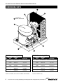
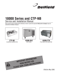
F13 Series
Service and Installation Manual
Please read this manual completely before attempting to install or operate this equipment!
Notify carrier of damage! Inspect all components immediately. See page 2.
Ice Cream Cabinets
N
CAUTIO
ION
T
A
M
R
INFO
T
N
A
T
R
USE
IMPO
E
R
O
F
E
NS!
O
I
T
C
READ B
U
NSTR
I
E
S
E
H
VE T
A
S
Effective December 2006
E
S
A
PLE
F13 Series Ice Cream Cabinets Service and Installation Manual
CONTENTS
SERIAL NUMBER LOCATION
SPECIFICATIONS......................................................2
RECEIVING & INSPECTING .....................................3
INSTALLATION ..........................................................3
OPERATION ..............................................................4
MAINTENANCE .........................................................4
PRESSURE SETTINGS .............................................4
WIRING DIAGRAMS ..................................................5
REFRIGERANT CHARGES & REPLACEMENT
PARTS................................................................. 6 & 7
STANDARD LABOR GUIDELINES............................8
WARRANTIES.................................................. 9 & 10
The serial number on self-contained units is located
behind the louver near the compressor. The serial
number on remote units is located in the mechanical
area on the right side.
Always have the serial number of your unit available
when calling for parts or service.
©2006 The Delfield Company. All rights reserved. Reproduction
without written permission is prohibited. “Delfield” is a registered
trademark of The Delfield Company.
SPECIFICATIONS
MODEL
NUMBER
GALLON
CAPACITY
NUMBER OF
COVERS
H.P.
VOLTS/HERTZ
PHASE
AMPS
BTU DESIGN
LOAD
BTU
SYS. CAP.
REF CHARGE
OZ.
SHIP
WEIGHT
Self-Contained Low Temp, Ice Cream Cabinet
F13WC32
12
2
1/3
115/60/1
8.0
322
818
24
311 lbs/141 kg
F13WC44
24
4
1/3
115/60/1
8.0
506
983
24
380 lbs/173 kg
F13WC56
36
6
1/3
115/60/1
8.0
638
1073
24
408 lbs/185 kg
F13WC68
48
8
1/3
115/60/1
8.0
796
1160
24
475 lbs/216 kg
NUMBER OF
COVERS
H.P.
VOLTS/HERTZ
PHASE
AMPS
BTU DESIGN
LOAD
EVAP. CAP.
BTU/°TD
5-15P NEMA plug used on all lengths
MODEL
NUMBER
GALLON
CAPACITY
SHIP
WEIGHT
Remote Low Temp, Ice Cream Cabinet
F13WR24
12
2
N/A
115/60/1
1.5
322
27/29
195 lbs/89 kg
F13WR36
24
4
N/A
115/60/1
1.5
506
38/26
255 lbs/116 kg
F13WR48
36
6
N/A
115/60/1
1.5
638
46/23
295 lbs/134 kg
F13WR60
48
8
N/A
115/60/1
1.5
796
56/21
345 lbs/157 kg
NUMBER OF
COVERS
H.P.
VOLTS/HERTZ
PHASE
AMPS
*Recommended horsepower
MODEL
NUMBER
GALLON
CAPACITY
BTU DESIGN LOAD BTU SYS. CAP. REF CHARGE
FRZR./RAIL
FRZR./RAIL
OZ.
SHIP
WEIGHT
Self-Contained Low Temp, Ice Cream Cabinet With Syrup Rail
F13BC44
24
4
1/3
115/60/1
F13BC56
36
6
1/3
F13BC72
48
8
1/2
NUMBER OF
COVERS
H.P.
8.0
506/192
983/828
24
435 lbs/197 kg
115/60/1
8.0
115/60/1
10.0
638/250
1073/979
24
480 lbs/218 kg
796/307
1309/1174
40
540 lbs/245 kg
VOLTS/HERTZ
PHASE
AMPS
5-15P NEMA plug used on all lengths
MODEL
NUMBER
GALLON
CAPACITY
BTU DESIGN LOAD BTU SYS. CAP.
FRZR./RAIL
FRZR./RAIL
SHIP
WEIGHT
Remote Low Temp, Ice Cream Cabinet With Syrup Rail
F13BR36
24
4
N/A
115/60/1
1.5
506/192
38/11
285 lbs/129 kg
F13BR48
36
6
N/A
115/60/1
1.5
638/250
46/14
340 lbs/154 kg
F13BR60
48
8
N/A
115/60/1
1.5
796/307
56/17
400 lbs/182 kg
2
For customer service, call (800) 733-8829, (800) 773-8821, (989) 773-7981, Fax (989) 773-3210, www.delfield.com
F13 Series Ice Cream Cabinets Service and Installation Manual
RECEIVING AND INSPECTING THE EQUIPMENT
Even though most equipment is shipped crated, care
should be taken during unloading so the equipment is
not damaged while being moved into the building.
1. Visually inspect the exterior of the package and
skid or container. Any damage should be noted
and reported to the delivering carrier immediately.
2. If damaged, open and inspect the contents with
the carrier.
3. In the event that the exterior is not damaged, yet
upon opening, there is concealed damage to the
equipment notify the carrier. Notification should
be made verbally as well as in written form.
4. Request an inspection by the shipping company
of the damaged equipment. This should be done
within 10 days from receipt of the equipment.
5. Check the lower portion of the unit to be sure legs
or casters are not bent.
6. Also open the machine compartment housing and
visually inspect the refrigeration package. Be sure
lines are secure and base is still intact.
7. Freight carriers can supply the necessary damage
forms upon request.
8. Retain all crating material until an inspection has
been made or waived.
Uncrating the Equipment
First cut and remove the banding from around the
crate. Remove the front of the crate material, use
of some tools will be required. If the unit is on legs
remove the top of the crate as well and lift the unit off
the skid. If the unit is on casters it can be "rolled" off
the skid.
INSTALLATION
Location
These units are for indoor use only. Be sure the
location chosen has a floor strong enough to support
the total weight of the cabinet and contents. Reinforce
the floor if necessary to provide for maximum loading.
For the most efficient refrigeration, be sure to provide
good air circulation inside and out.
Outside cabinet: Be sure that the unit has access to
ample air. It is suggested that the rear of the unit be
no less than two inches from any wall, partition or any
other object which will restrict exhaust air flow. Avoid
hot corners and locations near stoves and ovens.
Leveling
A level cabinet looks better and will perform better
because the cabinet will not be subject to undue strain.
Electrical connection
Refer to the amperage data on the serial
tag and your local code or the National
Electrical Code to be sure the unit is
connected to the proper power source.
A protected circuit of the correct voltage
and amperage must be run for connection
of the line cord or permanent connection
to the unit.
Self-contained models are provided with an a ON/OFF
power switch located directly behind the louvered panel
of the compressor section. Also located behind the
louver panel in the compressor section is the On/Off
switch for the heater wires. On the remote units the
thermostat may be provided with an OFF position which
shuts off only the solenoid valve.
The power switch must be turned to the
OFF position and power disconnected
whenever doing the following:
1) Performing maintenance functions.
2) Cleaning the refrigerated cabinet area.
3) Performing service or repair functions.
Under no circumstances should the unit
be operated without the louvered panel in
place!
If receptacles are to be mounted in the unit backsplash,
the power must be supplied from a separate electrical
source and installed in accordance with the national
Electrical Code and local electrical codes.
For customer service, call (800) 733-8829, (800) 773-8821, (989) 773-7981, Fax (989) 773-3210, www.delfield.com
3
F13 Series Ice Cream Cabinets Service and Installation Manual
OPERATION
These units use a “cold wall” design — heat is
removed from the storage compartments through the
liner walls. Products next to or touching the walls of
the compartment will often be colder than items at
the center of the compartment. For best results, store
items loosely and keep them away from the side walls
as much as possible.
take several hours to return to normal temperature,
Also, frequent or continuous opening of the lids can
affect the temperature in the storage compartment.
Freezer compartments
Freezer compartments are designed to hold ice cream
at 0°F to 5°F (-18°C to -15°C).
The units are not designed to reduce temperature
quickly. When overloaded with warm items, it may
MAINTENANCE
Cleaning
The interior and exterior can be cleaned using soap and warm water.
If this is not sufficient, try ammonia and water or non-abrasive liquid
cleaner. When cleaning the exterior, always rub with the “grain” of
the stainless steel to avoid marring the finish. Do not use an abrasive
cleaner because it will scratch the stainless steel and plastic.
In order to maintain proper refrigeration performance, the condenser
fins must be cleaned of dust, dirt, and grease regularly. It is
recommended that this be done at least every three months. If
conditions are such that the condenser is totally blocked in three
months, the frequency of cleaning should be increased. Clean the
condenser with a vacuum cleaner or stiff brush. If extremely dirty, a
commercially available condenser cleaner may be required.
The compartment lids should be cleaned as required to maintain their
ability to seal properly. A bristle brush and solution of soap and water
should be all that is required to keep the lids clean. Do not use full
strength degreasing agents on the rubber parts as they can cause the
rubber to crack and become brittle.
Cleaning solutions need to be alkaline based or non-chloride
cleaners. Any cleaner containing chlorides will damage the
protective film of the stainless steel. Chlorides are also commonly
found in hard water, salts, and household and industrial cleaners. If
cleaners containing chlorides are used be sure to rinse repeatedly
and dry thoroughly upon completion. Routine cleaning of stainless
steel can be done with soap and water. Extreme stains or grease
should be cleaned with a non-abrasive cleaner and plastic scrub
pad. It is always good to rub with the grain of the steel. There
are also stainless steel cleaners available which can restore and
preserve the finish of the steels protective layer. Early signs of
stainless steel breakdown can consist of small pits and cracks. If
this has begun, clean thoroughly and start to apply stainless steel
cleaners in attempt to restore the passivity of the steel.
Expansion Valve Location
The expansion valve location for remote and self-contained models is
located in the machine compartment of the unit.
Pressure Control
The temperature on self contained units is controlled by an
adjustable pressure control located in the machine compartment.
An adjustable control has the word COLDER near the knob, with
an arrow to indicate the adjustment direction. These controls
are field adjustable and do not require a service agent. If you
have any questions, feel free to contact the Delfield Service
Department.
In attempting to adjust the pressure control,
you can do damage to your unit by accidentally
adjusting the differential. Please make small
incremental adjustments if a temperature
adjustment is necessary, please contact the
service department at Delfield (800) 733-8829
or your local service agent. Delfield is not
responsible for charges incurred while having the
pressure control adjusted.
Factory recommended low-pressure control settings for
self-contained models are as follows:
Cut in 27# — cut out 11#
EPR valve for syrup rail is set at 65#
Defrosting
These units do not have an automatic defrost system. Defrosting
must be done manually after 3/8” frost accumulation. To defrost, turn
the power switch to OFF. Allow the frost to melt and mop up with a
sponge or soft cloth. When the defrost is complete, turn the power
switch back to ON.
Do not use sharp utensils to scrape frost because they
can damage important refrigeration components and
scratch or dent the liner.
4
For customer service, call (800) 733-8829, (800) 773-8821, (989) 773-7981, Fax (989) 773-3210, www.delfield.com
F13 Series Ice Cream Cabinets Service and Installation Manual
WIRING DIAGRAM: 13BC & WC SERIES
��
�
������
������
�
���������������
��������
�������
������
������
����������������
�������������������
������������
For customer service, call (800) 733-8829, (800) 773-8821, (989) 773-7981, Fax (989) 773-3210, www.delfield.com
5
F13 Series Ice Cream Cabinets Service and Installation Manual
CONDENSING UNITS
7
6
5
8
See below for
part# on receiver tank
1
3
4
2
1/3 H.P. Condensing Units
KEY
1/2 H.P. Condensing Units
DELFIELD
PART#
COPELAND
PART#
DESCRIPTION
KEY
DELFIELD
PART#
COPELAND
PART#
DESCRIPTION
3526711
FJAF-A050-IAA-201
1/2 H.P. low condensing unit 404A
3526710
M4YL-0035-IAA-201
1/3 H.P. low condensing unit 404A
1
3526749
AS13C1E-1AA-908
compressor
1
3526760
RS43C1E-IAA-958
compressor
2
2194469
040-C411-83
relay, current
2
2194473
040-0102-00
relay, current
3
2194452
014-0038-04
capacitor, starting
3
2194458
014-0008-57
capacitor, starting
4
2194462
071-C100-38
overload protector
4
2194466
071-0329-15
overload protector
5
—
050-0259-10
motor fan
5
—
050-0259-10
motor fan
6
—
066-C223-00
coil, condenser
6
—
066-0303-00
coil, condenser
7
—
083-0122-00
blade, fan
7
—
083-0130-00
blade, fan
8
—
077-C221-03
receiver tank
8
—
577-0346-02
receiver tank
Used on all F13WC units and on F13BC44 and F13BC56.
6
Used on F13BC72 only.
For customer service, call (800) 733-8829, (800) 773-8821, (989) 773-7981, Fax (989) 773-3210, www.delfield.com
F13 Series Ice Cream Cabinets Service and Installation Manual
REPLACEMENT PARTS LISTS
F13WR MODELS
REMOTE
Lid, large
Leg, 6” S/S, w/mount plate (4)
Valve, expansion, 1/4 Low, 404A
ON/OFF switch
3234188
3234645
3516225
2194099
F13WC MODELS
SELF-CONTAINED
Lid, large
Louver, 14”
Leg, 6” S/S, w/mount plate (4)
Condensing unit, 1/3 H.P., Low 404A
Valve, expansion, 1/4 Low, 404A
Cord & plug
ON/OFF switch
3234188
356-303-0030
3234645
3526710
3516225
2183348
2194099
F13BR MODELS
REMOTE
Lid, small
Pump, chocolate
Jar, syrup, white “poly”
Pump, regular syrup
Cover, lift, lid & spoon
Jar, crushed fruit
Leg, 6” S/S, w/mount plate (4)
Valve, expansion, 1/4 Low, 404A
ON/OFF switch
3234187
3234113
3234100
3234114
3234051
3234099
3234645
3516225
2194099
F13BC MODELS
SELF-CONTAINED
Lid, small
Pump, chocolate
Jar, syrup, white “poly”
Pump, regular syrup
Cover, lift, lid & spoon
Jar, crushed fruit
Louver, 14”
Louver, 18”
Leg, 6” S/S, w/mount plate (4)
Condensing unit, 1/3 H.P., Low 404A
Condensing unit, 1/2 H.P., Low 404A (72” only)
Valve, expansion, 1/4 Low, 404A
Valve, EPR 3/8 ODF, inlet/outlet
Control, low pressure
Cord & plug
ON/OFF switch
3234187
3234113
3234100
3234114
3234051
3234099
356-303-0030
356-303-0031
3234645
3526710
3526711
3516225
3516265
2193927
2183348
2194099
STANDARD REFRIGERANT CHARGES
1/3 low — 1/3 H.P. 24 oz. 404A
1/2 low — 1/2 H.P. 40 oz. 404A
There may be exceptions on specific
models. Charge amount should match
serial tag data.
For customer service, call (800) 733-8829, (800) 773-8821, (989) 773-7981, Fax (989) 773-3210, www.delfield.com
7
F13 Series Ice Cream Cabinets Service and Installation Manual
STANDARD LABOR GUIDELINES TO REPAIR OR REPLACE PARTS ON DELFIELD EQUIPMENT
Advice and recommendations given by Delfield Service Technicians do not constitute or guarantee any special coverage.
• A maximum of 1-hour is allowed to diagnose a defective component.
• A maximum of 1-hour is allowed for retrieval of parts not in stock.
• A maximum travel distance of 100 miles round trip and 2-hours will be reimbursed.
• Overtime, installation/start-up, normal control adjustments, general maintenance, glass breakage, freight damage, and/or
correcting and end-user installation error will not be reimbursed under warranty unless pre-approved with a Service Work
Authorization from Delfield. You must submit the number with the service claim.
LABOR OF 1-HOUR IS ALLOWED TO REPLACE:
• Thermostat
• Transformer
• Solenoid Coil
• Hi-limit/Thermal Protector Switch
• Compressor Start Components and Overload Protector
• Defrost Timer
• Thermometer
•
•
•
•
•
•
Contactor/Relay
Evaporator/Condenser Fan Motor and Blade
Circulating Fan Motor and Blade
Fan Delay/Defrost Termination Switch
Door Hinges, Locks, and Gaskets
Condensate Element
LABOR OF 2 HOURS TO REPLACE:
• Defrost Element
• Pressure Control
• Solenoid Valve
• Locate/Repair Leak
LABOR OF 3 HOURS TO REPLACE:
• EPR or CPR Valve
• Condenser or Evaporator Coil
• Expansion Valve
LABOR OF 4 HOURS TO REPLACE
• Compressor
This includes recovery of refrigerant and leak check.
$55.00 maximum reimbursement for refrigerant recovery (includes recovery machine, pump, torch, oil, flux, minor fittings,
solder, brazing rod, nitrogen, or similar fees.)
REFRIGERANTS
• R404A A maximum of $12.00/lb. or 75¢/oz. will be reimbursed.
8
For customer service, call (800) 733-8829, (800) 773-8821, (989) 773-7981, Fax (989) 773-3210, www.delfield.com
F13 Series Ice Cream Cabinets Service and Installation Manual
STANDARD ONE YEAR WARRANTY (One year parts, 90 days labor.)
The Delfield Company (“Delfield”) warrants to the Original Purchaser
of the Delfield product (herein called the “Unit”) that such Unit, and all
parts thereof, will be free from defects in material and workmanship
under normal use and service for a period of one (1) year from
the date of shipment of the Unit to the Original Purchaser or, if the
Original Purchaser returns the warranty card completely filled out
including the date of installation within thirty (30) days of receipt
of the Unit, one (1) year from the date of installation. During this
one year warranty period, Delfield will repair or replace any defective
part or portion there of returned to Delfield by the Original Purchaser
which Delfield determines was defective due to faulty material or
workmanship. The Original purchaser will pay all labor, crating, freight
and related costs incurred in the removal of the Unit of defective
component and shipment to Delfield, except that during a period of
either ninety (90) days from the date of shipment of the Unit to the
Original Purchaser or, if the Original Purchaser returns the warranty
card completely filled out including the date of installation within thirty
(30) days of receipt of the Unit, ninety (90) days from the date of
installation Delfield will pay all related labor costs. Delfield will pay the
return costs if the Unit or part thereof was defective.
The term “Original Purchaser” as used herein means that person, firm,
association, or corporation for whom the Unit was originally installed.
This warranty does not apply to any Unit or part thereof that has
been subjected to misuse, neglect, alteration, or accident, such as
accidental damage to the exterior finish, operated contrary to the
recommendations specified by Delfield; or repaired or altered by anyone
other than Delfield in any way so as to, in Delfield’s sole judgement,
affect its quality or efficiency. This warranty does not apply to any Unit
that has been moved from the location where it was originally installed.
This warranty also does not cover the refrigerator drier or the light
bulbs used in the Unit. The warranty is subject to the user’s normal
maintenance and care responsibility as set forth in the Service and
Installation Manual, such as cleaning the condenser coil, and is in
lieu of all other obligations of Delfield. Delfield neither assumes, nor
authorizes any other person to assume for Delfield, any other liability
in connection with Delfield’s products.
Removal or defacement of the original Serial Number or Model Number
from any Unit shall be deemed to release Delfield from all obligations
hereunder or any other obligations, express or implied.
Parts furnished by suppliers to Delfield are guaranteed by Delfield only
to the extent of the original manufacturer’s express warranty to Delfield.
Failure of the Original Purchaser to receive such manufacturer’s express
warranty to Delfield. Failure of the Original Purchaser to receive such
manufacturers warranty shall in no way create any warranty, expressed
or implied, or any other obligation or liability on Delfield’s part in respect
thereof.
IF THE CUSTOMER IS USING A PART THAT RESULTS IN A VOIDED
WARRANTY AND A DELFIELD AUTHORIZED REPRESENTATIVE
TRAVELS TO THE INSTALLATION ADDRESS TO PERFORM WARRANTY
SERVICE, THE SERVICE REPRESENTATIVE WILL ADVISE CUSTOMER
THE WARRANTY IS VOID. SUCH SERVICE CALLS WILL BE BILLED
TO CUSTOMER AT THE AUTHORIZED SERVICE CENTER’S THEN
APPLICABLE TIME AND MATERIALS RATES. CONSIDER: CUSTOMER
MAY INITIATE A SERVICE AGREEMENT WITHOUT PARTS COVERAGE.
If shipment of a replacement part is requested prior to the arrival in
the Delfield factory of the part claimed to be defective, the Original
Purchaser must accept delivery of the replacement part of a C.O.D.
basis, with credit being issued after the part has been received and
inspected at Delfield’s plant and determined by Delfield to be within this
warranty.
Under no condition does this warranty give the Original Purchaser the
right to replace the defective Unit with a complete Unit of the same
manufacturer or of another make. Unless authorized by Delfield in
writing, this warranty does not permit the replacement of any part,
including the motor-compressor, to be made with the part of another
make or manufacturer.
No claims can be made under this warranty for spoilage of any
products for any reason, including system failure.
The installation contractor shall be responsible for building access,
entrance and field conditions to insure sufficient clearance to allow
any hood(s), vent(s), or Unit(s) if necessary, to be brought into the
building. Delfield will not be responsible for structural changes
or damages incurred during installation of the Unit or any exhaust
system.
Delfield shall not be liable in any manner for any default or delay in
performance hereunder caused by or resulting from any contingency
beyond Delfield’s control, including, but not limited to, war,
governmental restrictions or restraints, strike, lockouts, injunctions,
fire, flood, acts of nature, short or reduced supply of raw materials, or
discontinuance of the parts by the original part manufacturer.
Except as provided in any Additional Four Year Protection Plan,
if applicable, and the Service Labor Contract, if applicable, the
foregoing is exclusive and in lieu of all other warranties, whether
written or oral, express or implied. This warranty supersedes
and excludes any prior oral or written representations or
warranties. Delfield expressly disclaims any implied warranties
of merchantability, fitness for a particular purpose of compliance
with any law, treaty, rule or regulation relating to the discharge of
substances into the environment. The sole and exclusive remedies
of any person relating to the Unit, and the full liability of Delfield
for any breach of this warranty, will be as provided in this warranty.
Other than this Delfield Standard One Year Limited Warranty, any
applicable Delfield Additional Four Year Protection Plan or applicable
Delfield Service Labor Contract, the Original Purchaser agrees and
acknowledges that no other warranties are offered or provided in
connection with or for the unit or any other part thereof.
In no event will Delfield be liable for special, incidental or
consequential damages, or for damages in the nature of penalties.
IF DURING THE WARRANTY PERIOD, CUSTOMER USES A PART
FOR THIS DELFIELD EQUIPMENT OTHER THAN AN UNMODIFIED
NEW OR RECYCLED PART PURCHASED DIRECTLY FROM DELFIELD
OR ANY OF ITS AUTHORIZED SERVICE CENTERS AND/OR THE PART
BEING USED IS MODIFIED FROM ITS ORIGINAL CONFIGURATION,
THIS WARRANTY WILL BE VOID. FURTHER, DELFIELD AND ITS
AFFILIATES WILL NOT BE LIABLE FOR ANY CLAIMS DAMAGES
OR EXPENSES INCURRED BY THE CUSTOMER WHICH ARISE
DIRECTLY OR INDIRECTLY, IN WHOLE OR IN PART, DUE TO THE
INSTALLATION OF ANY MODIFIED PART AND/OR PART RECEIVED
FROM AN UNAUTHORIZED SERVICE CENTER. If the warranty
becomes void, Customer may purchase from Delfield, if available,
a Service Agreement or service at the then current time and
materials rate.
For more information on Delfield warranty’s log on and check out the
service section of our web site at www.delfield.com.
For customer service, call (800) 733-8829, (800) 773-8821, (989) 773-7981, Fax (989) 773-3210, www.delfield.com
9
F13 Series Ice Cream Cabinets Service and Installation Manual
ADDITIONAL FOUR YEAR PROTECTION PLAN
Delfield Model#
Serial #
Installation
Date
In addition to the Standard One Year Warranty on the MotorCompressor contained in the above listed Delfield product (the
“Unit”), The Delfield Company (“Delfield”) also agrees to repair, or
exchange with similar or interchangeable parts in design and capacity
at Delfield’s option, the defective Motor-Compressor contained in the
Unit (the “Motor-Compressor), or any part thereof, for the Original
Purchaser only, at any time during the four (4) years following the
initial one (1) year period commencing on the date of installation for
the Original Purchaser. Failure of the Original Purchaser to register
the registration card containing the Original Purchasers name,
address, date of installation, model number and serial number of
the Unit containing the Motor-Compressor within 30 days from the
date of installation shall void this warranty. This additional warranty
is only available if the Motor-Compressor is inoperative due to defects
in material or factory workmanship, as determined by Delfield in
its sole judgement and discretion. The Original Purchaser shall be
responsible for returning the defective Motor-Compressor to Delfield
prepaid, F.O.B. at the address shown on the back cover of this manual.
The term “Original Purchaser” as used herein means that person, firm,
association, or corporation for whom the Unit was originally installed.
The term “Motor-Compressor” as used herein does not include unit
base, air or water cooled condenser, receiver, electrical accessories
such as relay, capacitors, refrigerant controls, or condenser fan/motor
assembly. This warranty does not cover labor charges incidental to
the replacement of parts. This warranty further does not include
any equipment to which said condensing unit is connected, such as
cooling coils, temperature controls or refrigerant metering devices.
This warranty shall be void if the Motor-Compressor, in Delfield’s
sole judgement, has been subjected to misuse, neglect, alteration
or accident, operated contrary to the recommendations specified
by the Unit manufacturer, repaired or altered by anyone other than
Delfield in any way so as, in Delfield’s sole judgment, to affect its
quality or efficiency or if the serial number has been altered, defaced
or removed. This Warranty does not apply to a Motor-Compressor in
any Unit that has been moved from the location where it was originally
installed. The addition of methyl chloride to the condensing unit or
refrigeration system shall void this warranty.
10
(for Motor-Compressor only)
General Conditions
Delfield shall not be liable in any manner for any default or delay
in performance hereunder caused by or resulting from any
contingency beyond Delfield’s control, including, but not limited
to, war, governmental restrictions or restraints, strike, lockouts,
injunctions, fire, flood, acts of nature, short or reduced supply
of raw materials, or discontinuance of any part or the MotorCompressor by the unit manufacturer.
Replacement of a defective Motor-Compressor is limited to one (1)
Motor-Compressor by us during the four (4) year period. Delfield
shall replace the Motor-Compressor at no charge.
This warranty does not give the Original Purchaser of the MotorCompressor the right to purchase a complete replacement MotorCompressor of the same make or of another make. It further does
not permit the replacement to be made with a Motor-Compressor
of another kind unless authorized by Delfield. In the event Delfield
authorizes the Original Purchaser to purchase a replacement
Motor-Compressor locally, only the wholesale cost of the MotorCompressor is refundable.
Expressly excluded from this warranty are damages resulting from
spoilage of goods.
Except as provided in any applicable Standard One Year Limited
Warranty or applicable Service Labor Contract, the foregoing
is exclusive and in lieu of all other warranties, whether written
or oral, express or implied. This Warranty supersedes and
excludes any prior oral or written representations or warranties.
Delfield expressly disclaims any implied warranties of
merchantability, fitness for a particular purpose or compliance
with any law, treaty, rule or regulation relating to the MotorCompressor, and the full liability of Delfield for any breach of this
warranty, will be as provided in this warranty.
Other than any applicable Delfield Standard One year Limited
Warranty, this Delfield Additional Four Year Protection Plan and any
applicable Delfield Service Labor Contract, the Original Purchaser
agrees and acknowledges that no other warranties are offered or
provided in connection with or for the Motor-Compressor or any
part thereof.
In no event will Delfield be liable for special, incidental or
consequential damages, or for damages in the nature of penalties.
For customer service, call (800) 733-8829, (800) 773-8821, (989) 773-7981, Fax (989) 773-3210, www.delfield.com
F13 Series Ice Cream Cabinets Service and Installation Manual
NOTES:
11
For customer service, call (800) 733-8829, (800) 773-8821, (989) 773-7981, Fax (989) 773-3210, www.delfield.com
Mt. Pleasant, MI
Covington, TN
Thank you for choosing Delfield!
Help is a phone call away. Help our team of professional, courteous
customer service reps by having your model number and serial number
available at the time of your call (800) 733-8829.
Model: ____________________ S/N: ___________________
Installation Date: ____________
For a list of Delfield’s authorized parts depots,
visit our website at www.delfield.com.
�������������������������������������������������������������������������������������������������������������������������������
����������������������������������������������������������������������������������������������������������������������������������������������������������������������
DM13
12/06