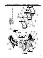
1
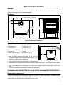
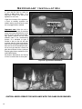
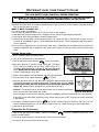
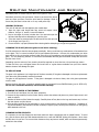
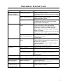
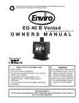
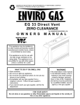
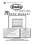
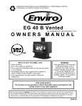
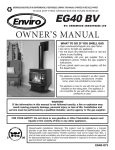
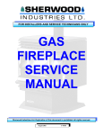
SHERWOOD INDUSTRIES IS AN ENVIRONMENTALLY RESPONSIBLE COMPANY. THIS MANUAL IS PRINTED ON RECYCLED PAPER.
PLEASE KEEP THESE INSTRUCTIONS FOR FUTURE REFERENCE
EG28 BV
BY: SHERWOOD INDUSTRIES LTD
OWNER’S MANUAL
WHAT TO DO IF YOU SMELL GAS
• Open windows/Extinguish any open flame.
• Do not try to light any appliance.
• Do not touch any electrical switch or use any phone in your
building.
• Immediately call your gas supplier from a neighbour’s phone.
Follow the gas supplier’s instructions.
• If you cannot reach your gas supplier, call the fire
department.
This appliance may be installed in an after market permanently
located, manufactured (mobile) home, where not prohibited by
local codes.
This appliance is only for use with the type of gas indicated on the
rating plate. This appliance is not convertible for use with other
gases, unless a certified kit is used.
WARNING
If the information in this manual is not followed exactly, a fire or explosion may
result causing property damage, personal injury or loss of life. Installation and
service must be performed by a qualified installer, service agency or the gas supplier.
FOR YOUR SAFETY
Do not store or use gasoline or other Flammable vapours and liquids in the vicinity of
this or any other appliance.
Massachusetts installations (Warning): This product must be installed by a licensed
plumber or gas fitter when installed within the Commonwealth of Massachusetts. Other
Massachusetts code requirements:-Flexible connector must not be longer than 36
inches, shut off valve must be a “T” handle gas cock, only direct vent sealed combustion
products are approved for bedroom/bathrooms, fireplace dampers must be removed or
welded in the open position prior to the installation of a fireplace insert or gas log.
EG28-121
Safety Precautions
FOR SAFE INSTALLATION AND OPERATION OF YOUR “ENVIRO” HEATER,
PLEASE CAREFULLY READ THE FOLLOWING INFORMATION:
• All ENVIRO gas-fired appliances must be installed
in accordance with their instructions. Carefully read all
the instructions in this manual first. Consult the building
authority having jurisdiction to determine the need for
a permit prior to commencing the installation.
• NOTE: Failure to follow these instructions could
cause a malfunction of the fireplace, which could
result in death, serious bodily injury, and/or property
damage.
• Failure to follow these instructions may also void
your fire insurance and/or warranty.
GENERAL
• Installation and repair should be done by a
qualified service person. The appliance should
be inspected before the first use and, annually
thereafter by a qualified service person. More frequent
cleaning may be required due to excessive lint from
carpeting, bedding material, etc. It is imperative the
control compartments, burners and circulating air
passageways of the appliance be kept clean.
• Due to high temperatures, the appliance should
be located out of high traffic areas and away from
furniture and draperies.
Children and adults should be alerted to the
hazards of high surface temperatures and
should stay away to avoid burns or clothing
ignition.
Young children should be carefully supervised
when they are in the same room as the
appliance.
FOR YOUR SAFETY
• Installation and service must be performed by a
qualified installer, service agency or gas supplier.
• This installation must conform to local codes or, in
the absence of local codes, to the current CAN/CGAB149 installation code (Canada) or National Fuel Gas
Code ANSI Z223.1.2 (USA).
• To prevent injury, do not allow anyone who is
unfamiliar with the stove to operate it.
2
• To prevent injury, if the pilot or pilot and
burners have gone out on their own, open the
glass door and wait 5 minutes to air out before
attempting to re-light the stove.
• Always keep the area around this appliance clear
of combustible material, gasoline and other flammable
liquids and vapours.
• This appliance should not be used as a drying
rack for clothing or for hanging Christmas stockings/
decorations.
• Due to the paint curing on the stove, a faint odor
and slight smoking will likely be noticed when the
stove is first used. Open a window until the smoking
stops.
Always connect this gas stove to a vent system and
vent to the outside of the building envelope. Never
vent to another room or inside the building. Make sure
the specified vent pipe is used; properly sized and of
adequate height to provide sufficient draft. Inspect
the venting system annually for blockage and signs of
deterioration.
WARNING: Failure to position the parts in accordance
with the diagrams in this booklet, or failure to use only
parts specifically approved with this appliance may
result in property damage or personal injury.
WARNING: Do not operate with the glass front
removed, cracked or broken. Replacement of the
glass must be done by a licensed or qualified service
person.
• Never use solid fuels such as wood, paper,
cardboard, coal, or any flammable liquids, etc., in this
appliance.
• Do not use this heater if any part has been under
water. Immediately call a qualified service technician
to inspect the heater and to replace any part of the
control or gas control systems that have been under
water.
• Do not abuse the glass by striking it or slamming
the door shut.
Table of Contents
Safety Precautions..........................................................................................2
Table of Contents...........................................................................................3
Codes And Approvals......................................................................................4
Specifications.................................................................................................5
Dimensions........................................................................................5
Clearances to Combustibles.................................................................5
Preparation For Installation.................................................................5
Initial Installation...........................................................................................6
Venting..............................................................................................6
Flue Gas Spill Switch...........................................................................6
Manufacturer’s General Venting Guidelines...........................................6
General Venting For The EG40.............................................................6
Termination........................................................................................7
Installation Into An Existing Chimney...................................................7
Straight Vertical Installation................................................................8
Electrical Requirements.......................................................................9
Replacing The Blower........................................................................10
Adjusting The Venturies....................................................................10
Fuel Conversion................................................................................11
Gas Line Connection and Testing.......................................................12
Secondary Installation...................................................................................13
Installation of Log Set and Embers.....................................................13
Operating Instructions..................................................................................15
Lighting Instructions.........................................................................15
Turning Gas Off To Appliance.............................................................15
Routine Maintenance and Service..................................................................16
Trouble Shooting..........................................................................................17
Parts List.....................................................................................................18
Parts Diagram - Chassis................................................................................20
Parts Diagram - Gas Tray & Door....................................................................21
Warranty......................................................................................................22
Installation Data Sheet.................................................................................23
3
Codes And Approvals
BV: This Vented appliance draws all of its combustion air from the dwelling and must be vented using listed B or L
vent. May also be vented through a conventional chimney using a chimney liner kit.
This appliance has been tested and approved for installations from 0 feet to 2000 (610 m) above sea
level.
In the USA: The appliance may be installed at higher altitudes. Please refer to your American Gas
Association guidelines which state: the sea level rated input of Gas Designed Appliances installed at
elevations above 2000 (610 m) feet is to be reduced 4% for each 1000 feet (305 m) above sea level.
Refer also to local authorities or codes which have jurisdiction in your area regarding the de-rate
guidelines.
In Canada: When the appliance is installed at elevations above 4500 feet (1372 m), the certified high
altitude rating shall be reduced at the rate of 4% for each additional 1000 feet (305 m).
•
This appliance has been tested by INTERTEK (Warnock Hersey) and found to comply with the
established VENTED GAS FIREPLACE HEATER standards in CANADA and the USA as follows:
VENTED GAS FIREPLACE HEATER (EG28 BV NG/LPG)
TESTED TO: ANSI Z21.88a-2003/CSA 2.33a-2003 VENTED GAS FIREPLACE HEATERS
CAN/CGA 2.17-M91 GAS FIRED APPLIANCES FOR HIGH ALTITUDES
CSA P.4.1-02 TESTING METHOD FOR MEASURING ANNUAL FIREPLACE EFFICIENCY
This ENVIRO EG28 BV Fireplace:
• Has been certified for use with either natural or propane gases. (See rating label.)
• Is not for use with solid fuels.
• Is approved for bedroom or bed sitting room. (IN CANADA: must be installed with a listed wall thermostat.
IN USA: see current ANSI Z223.1 for installation instructions.)
• Must be installed in accordance with local codes. If none exist, use current
installation code CAN/CGA B149 in Canada or ANSI Z223.1/NFPA 54 in the
USA.
• Must be properly connected to an approved venting system and not connected
to a chimney flue serving a separate solid-fuel burning appliance.
• Are approved for installation on combustible materials (i.e. Wood, carpet or
linoleum).
• Is not approved for closet or recessed installations.
IMPORTANT NOTICE (Regarding first fire up): When the unit is turned
on for the first time, it should be turned onto high without the fan on for the
first 4 hours. This will cure the paint, logs, gasket material and other products
used in the manufacturing process. It is advisable to open a window or door,
as the unit will start to smoke and can irritate some people. After the unit has
gone through the first burn turn the unit off including the pilot, let the unit get
cold then remove the glass door and clean it with a good gas fireplace glass
cleaner, available at your local ENVIRO dealer.
4
Specifications
WARNING:
Operation of this heater when not connected to a properly installed and maintained venting system can result in
carbon monoxide (CO) poisoning and possible death.
DIMENSIONS:
���
���� ���
�������� ������ ��� ��� ��� ���
��
���� ���
���
���� ���
�� ����
���� ���
���
���� ���
Figure 1: EG28 Exterior Dimensions.
CLEARANCES TO COMBUSTIBLES:
A. Sidewall to unit
B. Backwall to unit
C. Corner to unit
D. Combustibles to unit top
E. Floor to unit
F. Alcove maximum depth:
10 inches (25.4 cm)
4 inches (10.2 cm)
2 inches (5.1 cm)
22 inches (55.9 cm)
0 inches
48 inches (121.9 cm)
��
���� ���
��
��� ���
���
���� ���
• Locate a position where the flue system of the stove can
be properly installed without damaging the integrity of the
building; e.g. cutting a wall or ceiling joist.
Figure 2: Clearances to combustibles.
• Check stove and flue system clearance requirements.
• Locate the stove where it can be accessed by a gas supply line.
• Locate the stove in a large and open room that is centrally located in the house. This will optimize heat circulation
and comfort.
• As the stove is equipped with a convection fan, ensure that an electrical outlet is within 6 feet. (1.8 m) of the
stove.
• The flow of combustion and ventilation air must not be obstructed.
CLEARANCES MUST BE SUFFICIENT TO ALLOW ACCESS FOR MAINTENANCE AND SERVICE.
PREPARATION FOR INSTALLATION:
• Remove the packaging from the appliance, and check to make sure there is no damage. If damage is found,
please report it to both the carrier and your dealer as soon as possible.
• Before beginning, carefully check the glass door and the log set
5
Initial Installation
QUALIFIED INSTALLERS ONLY
VENTING:
This model must have a vent opening in the rear of the unit. Confirm this and also check that the label on the right
side panel door states “Vented Room Heater”.
WARNING: This appliance has been designed to operate by drawing combustion air and dilution air from the
room. The draft hood located in the same atmospheric pressure zone as the combustion air inlet to the appliance.
It is also designed to draw room air for proper heat circulation from the rear of the unit. Blocking or modifying the
louvers in any way can create hazardous situations, either through poor venting or by overheating. It is important
that this unit has sufficient air circulation for proper venting and combustion thus provisions must be made for the
supply of adequate combustion and ventilation air.
WARNING: Operation of this heater when not connected to a properly installed and maintained venting system or
tampering with the vent safety shutoff system can result in carbon monoxide (CO) poisoning and possible death.
THE APPLIANCE CANNOT BE CONNECTED TO A CHIMNEY FLUE SERVICING
A SEPARATE SOLID FUEL BURNING APPLIANCE.
FLUE GAS SPILL SWITCH:
NOTE: This heater must be properly connected to a venting system. This heater is equipped with a vent safety
shutoff system designed to protect against improper venting of combustion products. This safety switch is located
on the rear of the appliance close to the drafthood relief opening.
If the switch trips more than once, the chimney should be inspected by a qualified service
technician for possible blockage or severe down draught conditions.
MANUFACTURER’S GENERAL VENTING GUIDELINES:
This information is compiled by the manufacturer as a very general rule for single appliance venting of the EG40 gas
stove with 4 inch Type B gas vent. Refer to the Venting manufacturer’s directions for installation.
Venting code and regulations may vary from area to area, please check with the local, state/provincial codes
regarding the suitability of your application.
For other special venting requirements, please refer to the local, state/provincial or national codes.
The venting system should be assembled and installed according to the vent manufacturer’s instructions and the
local, state/provincial or national codes.
GENERAL VENTING FOR THE EG28:
This stove should be vented by certified 4” (10 cm) Type B Gas Vent or a flexible gas vent liner that may be encased
in 6” (15 cm) decorative stove pipe. The flue collar of the appliance will fit inside of standard vent and may be
fastened directly to the vent.
The ENVIRO incorporates its own internal draft hood, so no additional external draft hood is required.
Check periodically that the vent is unrestricted and an adequate draught is present when the unit is in operation.
6
Initial Installation
QUALIFIED INSTALLERS ONLY
TERMINATION:
�� �� ����� ���
The bottom of the vent cap shall extend at
least 2 feet (0.61 m) above the highest point
of the roof where it passes through and at
least 2 feet (0.61 m) higher than any portion
of the roof within a horizontal distance of 10
feet (3.1 m).
������ ����� ����
������� ������ ����
������������
� �� ���� ���
�������
� �� ���� ���
�������
See vent manufacturer’s instructions for vent
system clearances to combustibles and vent
terminal clearance from roof.
Figure 3: Height of Vertical Termination.
INSTALLATION INTO AN EXISTING CHIMNEY:
This basic venting configuration shown are rough guidelines only.
Follow national and local codes for other installation options.
Measure the height of the chimney beforehand and purchase
the appropriate kit. Never attempt to over stretch a flexible liner
to accommodate the height of the chimney.
• Any flue damper must be removed or locked permanently in
the open position.
• The chimney must be clean, in good working order and
constructed out of non-combustible materials.
• Make sure that all chimney clean-outs are tightly fitting and will
not permit air to leak into the chimney.
• Make all gas connections and check for leaks.
See vent manufacturer’s instructions for vent system clearances
to combustibles and vent terminal clearance from roof.
Figure 4: Installation into an existing chimney.
7
Initial Installation
QUALIFIED INSTALLERS ONLY
STRAIGHT VERTICAL INSTALLATION:
This basic venting configuration shown are rough
guidelines only. Follow national and local codes for
other installation options.
For the best venting performance, we recommend a
total vent height in the range of 10 feet (3.0 m) to 30
feet (9.1 m). The total horizontal length depends on
the number of elbows used; a 90° elbow accounts for
5 feet (1.5 m) of the horizontal run.
The venting should never slope down, a minimum 1⁄4
inch (0.6 cm) rise is needed for every 2 feet (61 cm)
of horizontal is recommended.
If practical, it is best to locate the appliance to permit
the use of shorter horizontals and fewer elbows.
Table 1. 90° elbows allowed verses the
horizontal length.
Number of 90° elbows
Maximum total horizontal
length allowed
2
20 feet (6.1 m)
3
13 feet (4.0 m)
4
6 feet (1.8 m)
5
0 feet (0 m)
Note: Using two (2) 45° elbows is equivalent to using
one (1) 90° elbow.
The venting rise should be a minimum of 1 foot (0.31
m) from the top of the unit before any horizontal run
are used.
Figure 5: Straight vertical installation.
8
Initial Installation
QUALIFIED INSTALLERS ONLY
ELECTRICAL REQUIREMENTS:
�
�
�
�
�
�
������
�����
����� ������
�����
�����
�����
• Operation of the fan increases the efficiency and the heat
output of the appliance.
����� ������
�����������
������
���
�
�
�
�
�
• The thermostat connects to the two purple wires in the
harness
�
�
�
�
�����
������
• Control panel light uses a 7 Watt max. bulb
�����
�����
• If the unit is installed in a Mobile Home it must be
connected to a grounding rod.
• If the unit is installed in a Mobile Home it must be
bolted securely to the floor.
�����
�����
�
�
�
�
����
����������
NOTE:
�����
�
�
�
�
�����
����
���
��
�
�
�
�
�
�
��� ����������
��
CAUTION: Label all wires prior to disconnection when
servicing controls. Wiring errors can cause improper
and dangerous operation. Verify proper operation after
servicing.
�����
DO NOT cut or remove the grounding prong from this
plug.
��
WARNING: Electrical grounding instructions. This
appliance is equipped with a three-prong (grounding)
plug for your protection against shock hazard, and must
be plugged directly into a properly grounded three-prong
outlet.
���
The ENVIRO EG40 will operate without electrical power. This model has a millivolt gas control, which uses the pilot
flame to generate enough electricity to operate the main burners. The appliance is equipped with a blower and must
be electrically connected and grounded in accordance with local codes or in the absence of local codes, with the
current CSA C22.1 CANADIAN ELECTRICAL CODE Part 1, SAFETY STANDARDS FOR ELECTRICAL INSTALLATIONS,
OR THE NATIONAL ELECTRICAL CODE ANSI / NFPA 70 in the U.S.
������ ��� �
�������� ����������
����
�
�
�
�
�
������
��� ����
���������
������
��� ������
���������
�����
������� ������ �� �����
Figure 6: EG40 BV Wiring Diagram.
O
O
N
FF
70 ° F
Table 2. Recommended Thermostat
Wire Size.
Wire Size
70 ° F
UP
Max. Length
14 gauge
100 ft (30.48 m)
16 gauge
60 ft (18.29 m)
18 gauge
40 ft (12.00 m)
20 gauge
25 ft (7.62 m)
22 gauge
18 ft (5.49 m)
DOWN
COOL / HEAT
PROGRAM
Figure 7: Wiring of a Thermostat
9
Initial Installation
REPLACING THE BLOWER:
1. Turn the unit off and remove the log set.
2. Remove the burner tray assembly by removing the
screw on either side of the tray, between the front and
rear burners. Lift the tray out.
3. Remove the four (4) 5/16” bolts that hold the blower
mounting plate to the back firewall. Use a light
lubricating oil on screws before removal.
5. Carefully pull the blower assembly into the firebox
(see Figure 8). Install the blower onto the mounting
bracket (blower outlets pointing through the two holes
in the bracket) using the 4 screws provided.
5. Connect wires according to the wiring diagram. If
removing the blower, disconnect the blower leads from
the harness. Remove the blower.
6. To re-install, check mounting plate gasket if damaged
replace with new one and reverse steps 1 through 4.
Refer to “Secondary Installation - Installation of Panel
Set” and “Secondary Installation - Installation of Log
Set and Embers”.
Figure 8: Blower (Fan) Removal.
ADJUSTING THE VENTURIES:
•
Remove the ash shelf by undoing the screw at each end, pull
shelf towards you.
•
Remove one screw from the cover plate located below the
ash shelf. Loosen the other screw (do not remove) swing the
cover plate out of the way and tighten screw down to hold it in
place.
•
With along screwdriver rotate spring clips to open or close the
shutter to the desired setting.
The venturies allows the amount of air coming into the fireplace to
be adjusted in order to accommodate different climates and venting
arrangements. Start the pilot and then the burner. Make sure the
pilot flame is burning normally and none of the burner ports are
plugged. Let the fireplace burn for roughly fifteen minutes and
then examine the flames, compare the flames to Figure 17.
Figure 9: Blower (Fan) Removal.
The ideal flame will be blue at the base and light orange above. The flames should be of medium height. If the
flames look like this, no venturi adjustment is needed. If the flames are fairly short and mostly blue, the fireplace
is getting too much air. Therefore, the venturies should be closed slightly until the correct flames are achieved.
Flames that are very orange, with tall, dark, stringy tips, are not getting enough air. Open the venturi until the
flames clean up. If the venturi is opened, or closed all the way, and the correct flames cannot be attained, turn off
the gas and contact the dealer.
Warning: Incorrect venturi adjustment may lead to improper combustion, which is a safety hazard. Contact the
dealer if there is any concern about the venturi adjustment.
10
Initial Installation
FUEL CONVERSION:
WARNING: This conversion kit shall be installed by a qualified service technician
in accordance with the manufacturer’s instructions and all applicable codes and
requirements of the authority having jurisdiction. If the information in these instructions
is not followed exactly, a fire, explosion or CO poisoning may result. The qualified service
agency is responsible for the proper installation of this kit. The installation is not proper
or complete until the operation of the converted appliance is checked as specified in the
owner’s conversion kit.
Please read and follow these instructions. Also please read the instruction guidelines provided by S.I.T on how to
remove and install the HI-LOW regulator.
STEP 1. Carefully inspect all parts supplied with this conversion kit.
STEP 2. Shut the gas off and disconnect the main gas line from the unit.
STEP 3. Open the door by unscrewing the 1⁄2” bolt on the right hand side of the stove. Lift door off the hinges
mounted on the left-hand side.
STEP 4. Carefully remove the log set and ember material if they are installed.
STEP 5. Remove the two (2) T-20 screws on the burner tray located between the front and rear burners.
STEP 6. Change the regulator on the top of the gas valve. (Follow the instructions provided by S.I.T)
STEP 7.
To change the pilot, pull the pilot hood straight up to access the pilot injector, using a 5/32” Allen key,
remove the pilot injector.
STEP 8. Install new pilot injector supplied with the conversion kit. Screw the new injector inside the pilot assembly
and re-install the hood by placing the hood on the assembly, line up the keyway and snap into place
STEP 9. Remove the two (2) main burner orifices using a 1⁄2” deep socket.
STEP 10. Install the two (2) new orifices supplied making sure that the orifices are in the correct location. Be sure
to put a bead of pipe thread sealant or approved Teflon tape on the orifices before installing them into
the burner assembly.
STEP 11. Re-install burner tray, log set and door. Also refer to “Installing Log Set and Embers.”
STEP 12. Reconnect the gas line to the unit. Do a leak check using soap and water solution or an approved method
on the gas supply and the pilot tubing.
STEP 13. Re-light the appliance to ensure proper operation and proper flame appearance. Be sure to adjust the
venturi setting to achieve an efficient flame in the fireplace.
STEP 14. MAKE SURE that the sticker provided by S.I.T is installed to signify that this valve has been converted to
a different type of fuel. Also make sure that the rating plate has a conversion label to show that this unit
has been converted to a different fuel type.
A VISUAL CHECK OF THE REGULATOR KNOB IS NECESSARY TO DETERMINE WHETHER OR NOT THE REGULATOR
IS THE CORRECT PART. A 50% TURN DOWN REGULATOR WILL HAVE ONLY ONE CORNER ON THE KNOB.
1 - 50% turn down HI-LOW Regulator
3 - T-20 Torx screws
1 - T-20 tamper proof Torx screwdriver bit
1 - pilot injector
2 - Main orifice
Labels to show conversion.
Natural Gas
Propane
.62 mm
.35 mm
Burner Orifice
#43 DMS
#53 DMS
Venturi Setting
1/16”
Pilot Orifice
min.
1⁄4” Min
Table 3: Orifice Information.
11
Initial Installation
GAS LINE CONNECTION AND TESTING:
WARNING: Only persons licensed to work with gas piping may make the necessary gas connections to this
appliance.
GAS LINE CONNECTION
•
This stove is equipped with a certified flexible pipe located on the right side of the unit terminating in a 3⁄8” male
NPT fitting. Consult your local authorities codes or the CAN/CGA B 149 (1 or 2) installation code in Canada, or
in the USA gas installations follow either local codes or the current edition of the National Fuel Gas Code ANSI
Z223.1.
•
The efficiency rating of this appliance is a product thermal efficiency rating determined under continuous
operating conditions and was determined independently of any installed system.
The appliance and its shutoff valves must be disconnected
from the gas supply piping system during any pressure
testing where the pressure exceeds 1⁄2 PSIG (3.45 KPa)
or damage will occur to the valve.
IN
OUT
L
O
I
O FF
PI L OT
TH
ON
LO
PI T
TO TEST VALVE PRESSURES
H
TP
Always check for gas leaks with a soap
and water solution after completing the
required pressure test.
TP TH
The appliance must be isolated from the gas supply
piping system by closing its individual manual shutoff
valve during any pressure testing of the gas supply
piping system at test pressures equal to or less than 1⁄2
psig (3.45 KPa).
�����
�������� ���
��������
�������� ���
����� ����������
�����
������
����
��� �������
����
Figure 10: Fully Labeled Gas Valve.
The pressure taps are located on the left side of the valve
• Turn set screw 1 turn counter clockwise to loosen,
• Place 5/16” (8 mm) I.D. hose over pressure tap system.
• Check pressures using a manometer.
• When finished, release pressure, remove hose & tighten setscrew.
Table 4: Pressure and BTU Information.
Main Orifice
Manifold Pressure
Min. Manifold Pressure
Max Supply Pressure
Min. Supply Pressure
Max BTU/hr Input
Min. BTU/hr Input
Natural Gas
#43 DMS
3.8” W.C. (0.95 KPa)
1.1” W.C. (0.27 KPa)
7.0” W.C. (1.74 KPa)
5.0” W.C. (1.25 KPa)
26,500 BTU/hr (7.87 KW)
13,500 BTU/hr (3.9 KW)
Propane
#53 DMS
11.0” W.C. (2.74 KPa)
2.7” W.C. (0.67 KPa)
12.0” W.C. (2.98 KPa)
11.5” W.C. (2.86 KPa)
26,500 BTU/hr (7.87 KW)
13,500 BTU/hr (3.9 KW)
NEVER USE AN OPEN FLAME FOR LEAK TESTING.
12
Secondary Installation
INSTALLATION OF LOG SET AND EMBERS:
The placement of the logs is not arbitrary.
If they are positioned incorrectly, the
flames can be “pinched” and will not burn
correctly. The burner come with five (5)
locator pins and two (2) resing areas,
which make alignment easier. Using the
pictures provided, carefully set the logs in
place.
NOTE: The logs are fragile and should
be handled gently.
CAUTION: Use only the type of ember
material supplied with this appliance. Due
to the irregular size of the ember material
there may be more than required. The use
of other foreign materials on the burners
may create dangerous conditions.
Figure 11: Step 1 of Log Placement.
If over time, through cleaning and servicing,
these embers require replacement, contact
the nearest ENVIRO dealer for replacement
embers.
1. The embers can be place before or after
the logs are placed. A bag of ceramic fiber
embers and rock wool embers is provided
gently remove the ember material from
the plastic bag. Spread a layer loosely in a
random manner across the burner tray. Do
not allow any embers to rest against pilot
assembly. (See Figure 13 or 16 for proper
ember placement.)
Figure 12: Step 2 of Log Placement.
DO NOT pack this ember material as this
could create an unsafe condition, leave
embers loose
2. Carefully remove logs from box. Check
to ensure there is no damage. It is very
important to install all logs in their proper
position to insure safe, optimum operating
conditions.
3. Place the log set into the firebox.
Locate each log by seating it down onto the
burner tray support pins. Follow Figures 11
to 16 proper log placement.
Figure 13: Step 3 of Log Placement.
Resting Area and
Placement Pin for Right Log
Figure 14: Step 4 of Log Placement.
13
Secondary Installation
4. Upon the first light up, watch for
ignition to ALL burner ports. If a
long delay is noted: First, wait for the
appliance to cool down.
• Open the front door of the appliance.
• Check to carefully reposition the
embers making sure that burner ports
are not plugged solid or blocked.
Important note: When the unit is
turned on for the first time, It should be
turned onto high without the fan on for
the first 4 hours. This will cure the paint,
logs, gasket material and the other
products used in the manufacturing
process. It is advisable to open a
window or door, as the unit will start
to smoke and can irritate some people.
After the unit has gone through the first
burn turn the unit off including the pilot,
let the unit get cold then remove the
glass door and clean it with a good gas
fireplace glass cleaner, available at your
local ENVIRO dealer.
Resting Areas for
Center Log
Figure 15: Step 5 of Log Placement.
See Routine Maintenance And Service
on how to remove door to clean glass.
Figure 16: Log Placement with Embers.
Figure 17: Appliance Burning.
CAUTION: NEVER OPERATE THIS APPLIANCE WITH THE GLASS DOOR REMOVED.
14
Operating Instructions
FOR YOUR SAFETY READ COMPLETELY BEFORE OPERATING.
WARNING: IF YOU DO NOT FOLLOW THESE INSTRUCTIONS EXACTLY, A FIRE OR EXPLOSION
MAY RESULT CAUSING PROPERTY DAMAGE, PERSONAL INJURY OR LOSS OR LIFE.
A) This appliance is equipped with a pilot that must be lit by hand by following these instructions exactly.
B) BEFORE LIGHTING smell all around the appliance area for gas, and next to the floor because some gas is heavier
than air and will settle on the floor.
WHAT TO DO IF YOU SMELL GAS:
• Do not try to light any appliance.
• Do not touch any electrical switch; do not use any phone in your building.
• Immediately call your gas supplier from a neighbor’s phone. Follow the gas supplier instructions.
• If you cannot reach your gas supplier, call the fire department.
C) Use only your hand to push in or turn the gas control knob. Never use tools. If the knob will not push in or turn
by hand, do not attempt to repair it. Call a qualified service technician. Force or attempted repair may result in
a fire or explosion.
D) Do not use this appliance if any part has been under water. Immediately call a qualified service technician to
inspect the appliance and to replace any part of the control system and any gas control which has been under
water.
LIGHTING INSTRUCTIONS:
1. STOP! Read the safety information above.
2. Turn off all electrical power to the appliance.
3. Turn the gas control knob clockwise
to the “off’ position.
4. Open door. Wait five (5) minutes to clear out any gas. Close door.
If you smell gas including near the floor, STOP! Follow “B” in
the above safety information. Leak test all gas joints with soapy
water NEVER USE AN OPEN FLAME FOR LEAK TESTING. If
you don’t smell gas go to next step.
Figure 18: Gas Valve.
5. Find the pilot located to the right between the front and rear burner.
6. Turn gas control knob counter-clockwise
to “PILOT”.
7. Push the gas control knob in fully and hold. A BATTERY operated electronic igniter
will light the pilot. Keep knob depressed for about 30 seconds after pilot is lit. Check
that the pilot flame has fully engulfed the thermocouple assembly (see
Figure 19). Release knob. If pilot goes out, repeat steps 4 through 6.
Thermopile
Thermocouple
WARNING: The gas valve has an lockout device which will not allow the pilot burner
Figure 19: Pilot Burning.
to be re-lit until the thermocouple has cooled.
If the knob does not pop up when released, stop and immediately call your service technician or gas supplier.
If the pilot will not stay lit after several tries, turn the gas control knob to “OFF” and call your service technician
or gas supplier.
8. Turn gas control knob counter-clockwise
to the “ON” position. Flip burner switch to “ON”. Turn “HI / LO”
knob to the desired setting. Turn on all electrical power to the unit. Check that all burner ports have flame.
9. Leak test all gas joints again.
TURNING GAS OFF TO APPLIANCE:
1. Depress the gas control knob slightly and turn it clockwise
position. DO NOT FORCE
to “PILOT”. Repeat to turn to the “OFF”
2. Turn off all electrical power to the appliance if service is to be performed.
3. Flip burner switch to off, to turn off burners only.
15
Routine Maintenance and Service
Periodically check to ensure that your direct vent system is clean.
Periodically check the pilot and burner. Check to see that all the burner
ports are clean and clear. Check the pilot head for blockage. Check to
ensure the pilot flame is blue with no or very small yellow tips.
OPENING THE DOOR
Turn unit off and wait until the appliance has cooled down.
1. Open the right hand hinged side flap, which will expose a door
���� ��
��� ������ �����
fastener. Using a 1⁄2” wrench, loosen the fastener.
2. Due to the shape of the bay window door. You must also open the
left-hand side flap before attempting to open the door.
3. If the door must be removed open the door and lift the door pins out
Figure 20: Removing the Door.
of the hinges (see figure 20).
4. Ensure the door is properly fastened after cleaning before attempting to re-light the appliance.
CLEANING THE GLASS (Allow the glass to cool before cleaning.)
It will be necessary to clean the ceramic glass periodically. During a cold start up, condensation will sometimes form
on the glass. This is a normal condition with all gas fireplaces and stoves. However, this condensation can allow
dust and lint to cling to the glass surface. Initial paint curing of the appliance can leave behind a slight film on the
glass. This is a temporary problem. It is therefore recommended that the glass be cleaned initially after about the
first four hour of use.
Depending upon the amount of use, cleaning should be required no more than two or three times per season.
To clean the door, use a mild glass cleaner and a soft cloth or a glass cleaner available from your Enviro dealer.
Abrasive cleaners will damage the glass.
TO REPLACE DOOR
The glass in this appliance is an integral part of the door assembly. If the glass is damaged or broken a replacement
inner door with glass assembly must be purchased.
The glass in this appliance is ceramic. If the glass is damaged or broken a factory door with glass replacement
must be used.
Remove the door with glass, a new door assembly must be purchased from an ENVIRO dealer (part #: EG28-103).
Do not use a substitute materials; it will void the warranty.
CLEANING THE INSIDE OF THE FIREBOX
1. Turn off the unit and allow it to cool down completely.
2. Remove the logs carefully from the firebox. Gently remove the embers and place on a piece of paper towel, until
ready to replace.
3. Vacuum the bottom of the firebox thoroughly. Carefully clean off any dust on the logs and remove any lint from
the main burner and pilot burner.
4. After carefully replacing the log and embers in their correct positions (see Secondary Installation - Installation of
Log Set and Embers), and the door has been resealed, re-light the pilot, following the instructions on the lighting
label attached to the unit.
CLEANING PLATED SURFACES:
It is important to note that fingerprints and other marks can leave a permanent stain on plated finishes. To avoid
this, give the face a quick wipe with denatured alcohol on a soft cloth BEFORE lighting the fireplace. Never clean
the face when it is not cool. Do not use other cleaners as they may leave a residue, which can become permanently
etched into the surface.
16
Trouble Shooting
Problem
Possible Cause
Spark will not light the
Defective piezo ignitor.
pilot after repeatedly
pressing the spark ignitor
Solution
• Check connections to ignitor.
• If ignitor connections are good but there is no spark;
replace ignitor.
Broken spark electrode.
• Check for broken ceramic insulation.
• Replace electrode if broken.
Misaligned spark electrode.
• If spark is not arcing from electrode to pilot - adjust
by loosening the screws on the pilot base. Adjust
away from burner and retighten.
Problem with thermocouple
circuit.
• Check for proper connection of the thermocouple to
the rear of the valve. If loose, tighten lightly.
• Check pilot for full flame impingement around
thermocouple. If flame is too small, check gas
pressure, adjust pilot rate screw, check pilot head for
damage or blockage.
• Check thermocouple voltage at rear of valve. It must
be greater than 5 mV. If low, replace thermocouple.
Air in gas line (pilot dies
while knob is depressed).
• Bleed line.
• Check gas line pressure.
• Contact dealer.
Burners will not remain
lit
Problem with thermopile
circuit.
• Check gas line pressure .
• Check for flame impingement on thermopile. If low,
see “Pilot will not remain lit”.
• Check thermopile for minimum of 200 mV when
burner is switched on.
• Check wiring to thermostat for breaks.
Flame lifting
Leak in vent pipe.
• Check for leaks in vent connections.
Improper vent
configuration.
• Check vent configuration with manual.
Terminal may be
recirculating flue gases.
• Check to see if the terminal is on correctly.
• May need to install high wind termination cap.
• Contact dealer.
Pilot will not remain lit
Glass fogs up
Normal Condition: after the appliance warms up the glass will clear.
**Due to additives in gas, glass may get hazy during operation** Clean as needed.
Blue Flames
Normal during start up: flames will yellow as the fireplace heats up.
Flames are burning
“dirty” or sooting
Flame impingement
• Check log positioning.
• See also “Burners will not remain lit.”
Flame goes out / comes
on frequently during a
short period of time.
Defective rocker switch.
• Check rocker switch connections.
• Replace switch if necessary.
17
Parts List
Reference Number
Part Number
120°F (49°C) Ceramic Temperature Sensor
EC-001
2
Spill Switch 220°F (121°C)
EC-002
3
SIT Nova Valve NG 50%
EC-006
3
SIT Nova Valve LP 50%
EC-007
4
Thermocouple
EC-009
4
Spark Electrode with Cable
EC-011
4
Thermopile
EC-012
4
Pilot NG with Electrode
EC-013
4
Pilot LP with Electrode
EC-014
4
Fully Assembled Pilot NG
EC-015
4
Fully Assembled Pilot LP
EC-016
4
Pilot Orifice NG
EC-019
4
Pilot Orifice LP
EC-020
Pilot Gasket
EC-021
S.I.T. Piezo Ignitor
EC-023
Stainless Steel Flex Connector with 3/8” Elbow 18” Long
EC-024
Burner Switch
EC-025
Fan Access Cover Gasket
EC-029
7
Miniature Light Bulb - 115V
EC-031
7
Light Bulb Holder
EC-032
5
6
Wiring Harness Complete (2 pieces)
EC-037
Burner Wiring Harness
EC-037A
Body Wiring Harness
EC-037B
Fan Controller Knob
EC-040
IEC Power Cord - 115 V
EC-043
4oz Bag Coal Embers Only
EC-045
Log Set with Embers
EC-048
Aluminum Manifold
EC-049
8
1” x 1” Side Cabinet Hinge
EC-054
9
Pedestal Door Magnet
EC-056
3/8” Tadpole Door Gasket (7 feet)
EC-057
Door Latch Bolt
EC-059
Fan Impeller
EC-064
10
18
Part Description
1
Door Nut Mounting Bracket
EC-065
11
Light Switch
EC-066
12
Fan Controller with Knob - 115V
13
Side Panel Magnet Bracket
EG28-027
Envirogas EG28 Name Plate
EG28-076
Latch Bracket and Nut
EG28-095
14
Complete Inner Door with Glass
EG28-103
15
Pedestal
EG28-108
EF-045
Parts List
Reference Number
Part Description
Part Number
16
Pedestal Door
EG28-109
17
Burner Tray Top - LP / NG
EG28-116
17
Pan Burner Tray Top
EG28-116A
BV Owner’s Manual
EG28-121
18
Cabinet Side Panel
EG28-123
19
BV Stove Top
EG28-124
Firebox Baffle
EG28-125
Fan Kit
EG28-127
20
BV Top Baffle
EG28-132
21
Wire Channel
EG28-139
Pedestal Wiring Plate
EG28-140
22
Pedestal Back
EG28-141
23
Burner with NOVA SIT Valve NG
EG28-143
23
Burner with NOVA SIT Valve LP
EG28-145
24
Ash Shelf
EG28-150
Door Hinge Bracket
EG28-161
25
Door Latch Bracket
EG28-162
26
BV 4” Crimped Flue Pipe
EG28-169
LP To NG Conversion Kit
EG28-201
NG To LP Conversion Kit
EG28-203
Glass Set with Gasket
EG28-205
Thermocouple Pilot Nut
EG28-210
28
Fan Mounting Bracket
EG28-304
29
Venturi
EG31-099
27
Control Panel Decal
30-044
Rear Exterior Back Panel
30-045
Control Panel Front and Decal
30-069
Blower Mount Screws (4)
50-086
31
Blank Orifice #74
50-343
32
Glass Extrusions (set of 2)
50-483
33
Convection Blower - 115V (no mount)
50-512
16” Ignitor Wire
50-652
32
Bar Set (4 Pieces) - Nickel
50-475
32
Bar Set (4 Pieces) - Painted
EG28-152
32
Bar Set (4 Pieces) - Gold
EG28-153
33
Door Cover - Gold
50-476
33
Door Cover - Painted
50-757
33
Door Cover - Brushed Nickel
50-1064
34
Door Assembly with Glass (A+B) - Brushed Nickel
50-1065
34
Door Assembly with Glass (A+B) - Painted
EG28-099
34
Door Assembly with Glass (A+B) - Gold
EG28-101
30
19
Parts Diagram - Chassis
��
��
�
��
��
��
��
��
��
�
�
��
��
��
��
�
��
EG 28 Body (Chassis)
July 2004
20
��
��
��
��
��
��
��
�
�
�
�
�
��
��
July 2004
��
��
��
��
EG 28 Gas Tray and Door Assemblies
��
Parts Diagram - Gas Tray & Door
21
Warranty
Sherwood Industries Ltd. offers a Limited Lifetime Warranty on this gas product. This limited lifetime warranty
covers the appliance for a period of seven years from the date of installation. This warranty applies only to the
original owner in the original location
Covered under the lifetime warranty are Cabinet Sides, Tops, Pedestals, Surround Panels and Chassis and Heat
Exchanger. These steel components are covered against manufacturer’s defects for 5 years and labor for the first
year and for parts only thereafter.* The following exclusions apply:- over-firing due to incorrect setup or tampering,
damage caused by incorrect installation, usage or abuse. The unit must be properly installed by a qualified
technician or installer, and must meet all local and national gas and building code requirements.
We also cover against manufacture defects under our lifetime warranty. The following components,
Gold Plating, Log Set, Burners and Glass (*) The following exclusions apply:
Gold plating- Damage caused by scratching, marring, chemicals, fingerprints, abrasive cleaners or discoloration with
age or over-firing
Glass- use of harsh or abrasive cleaners, striking the glass or surface contaminates.
Log-set- Damage caused by incorrect handling or misuse.
Burners- damage caused by improper or continuous operation under incorrect conditions.
The paint on the Metal Brick Liner may peel. This is due to the extreme conditions applied to the paint and is no
way covered under warranty.
* TO A MAXIMUM OF SEVEN YEARS
Sherwood Industries Ltd. offers a 2-year warranty on all the Electrical Components and Gas Components against
manufacturing defects. Paint is covered against flaking. This offer includes parts and labor for 1 year and for parts
only thereafter.
Your dealer shall make all claims under this warranty in writing.
WHEN FILING A WARRANTY CLAIM PLEASE COMPLETE THE FOLLOWING INFORMATION ON AN
OFFICIAL WARRANTY CLAIM FORM:
TO THE DEALER
Name, address and telephone number of purchaser and date of purchase.
Date of installation. Name of installer and dealer. Serial number of the appliance. Nature of complaint, defects or
malfunction, description and part numbers of any parts replaced.
TO THE DISTRIBUTOR
Sign and verify that work and information are correct.
This warranty covers defects in materials and workmanship only if the product has been installed according to the
manual’s instructions. If the product is damaged or broken as a result of misuse or mishandling the warranty does
not apply. The warranty does not cover removal and re-installation costs.
Sherwood Industries Ltd. reserves the right to repair or to replace the defective product. The shipping costs are to
be paid by the consumer. All warranties by the manufacture are set forth herein and no claim shall be made against
the manufacturer on any oral warranty or representation.
Sherwood Industries Ltd. and its employees or representatives will not assume any damages, either directly or
indirectly caused by improper usage, operation, installation, servicing or maintenance of this appliance.
Sherwood Industries Ltd. reserves the right to make changes without notice. Please complete and mail the warranty
registration card and have the installer fill in the installation data sheet in the back of the manual for warranty and
future reference.
22
Installation Data Sheet
The following information must be recorded by the installer for warranty purposes and future reference.
NAME OF OWNER:
NAME OF DEALER:
_________________________________________
_________________________________________
ADDRESS:
ADDRESS:
_________________________________________
_________________________________________
_________________________________________
_________________________________________
_________________________________________
_________________________________________
PHONE:___________________________________
PHONE:___________________________________
MODEL:___________________________________
NAME OF INSTALLER:
SERIAL NUMBER:___________________________
DATE OF PURCHASE: _____________
DATE OF INSTALLATION:___________(dd/mm/yyyy)
� NATURAL GAS (NAT)
_________________________________________
(dd/mm/yyyy)
� PROPANE(LPG)
ADDRESS:
_________________________________________
_________________________________________
_________________________________________
INLET GAS PRESSURE:_________in wc
PHONE:___________________________________
MAIN BURNER ORIFICE:__________# DMS
PILOT ORIFICE #_________OR________in diam.
INSTALLER’S SIGNATURE:
_________________________________________
MANUFACTURED BY:
SHERWOOD INDUSTRIES LTD.
6782 OLDFIELD RD. SAANICHTON, BC, CANADA V8M 2A3
www.envirofire.biz
February 21, 2005
C-10451
23