1
1 Preface
With the business servers in the SX series (abbreviated to: SX servers), Fujitsu Siemens
Computers is pursuing its strategy of opening up the BS2000/OSD operating system by
making available a modern hardware solution which is based on SPARC64™ technology
and represents a future-safe investment for the customer.
The OSD Extended Configuration (OSD/XC) software package includes a ported variant of
the BS2000/OSD basic configuration which offers high performance when run on the
SX servers' SPARC64 architecture. Further software packages included in the OSD/XC
package extend the functionality available in the basic configuration. Existing BS2000/OSD
applications in the /390 world offer full object compatibility, i.e. they require no modifications,
when run on the SPARC64 architecture of the SX servers.
The SX server hardware is based on the PRIMEPOWER server hardware. The business
servers in the SX series can be divided into two classes: on the one hand the partitionable
models, with facilities for using several separate runtime environments for BS2000/OSD
and Solaris™ applications, and on the other hand the entry-level models without partitioning
which offer a cost-effective way of entering the SX server series.
The hardware of the partitionable models is designed so that existing hardware components (CPU, main memory, controllers, disks, etc.) can be distributed across multiple partitions. This means that different, independent operating systems together with their available
applications can be run on separate partitions. These operating systems and applications
do not affect each other when they are running.
With their high availability and scalability, and the capacity for the parallel operation of
several independent application environments, the partitionable SX server models provide
an optimum basis for enterprise and business applications and for server and storage
consolidation. At the same time they also open up the SX series to the varied application
environment of the Solaris™ operating system.
The SX100 series models are the entry-level models of the SX series. These non-partitionable models are designed exclusively for use with BS2000/OSD. The SX series entry-level
models with their high availability and favourable total-cost-of-ownership (TCO) form an
optimum basis for the BS2000/OSD entry-level both for proven enterprise applications and
for new enterprise and E-business solutions.
U41272-J-Z385-3-76
1
Preface
All SX series models have the latest processor technology and optional fibre channel
interface technology for fibreCAT disk systems with possible SAN integration. These
features ensure that SX series models are a future-safe investment.
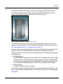
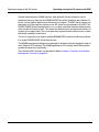
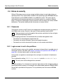
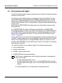
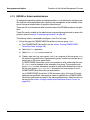
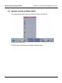
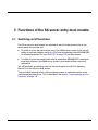
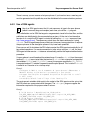
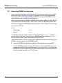
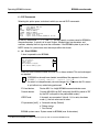
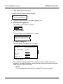
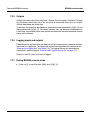
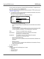
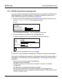
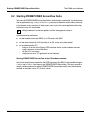
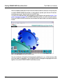
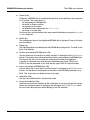
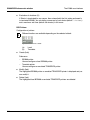
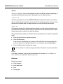
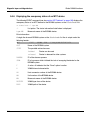
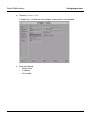
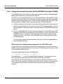
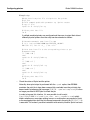
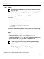
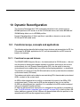
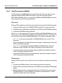
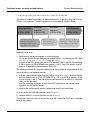
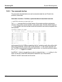
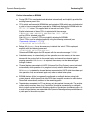
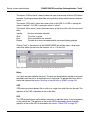
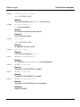
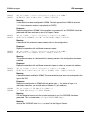
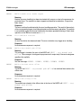
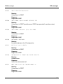
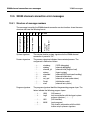
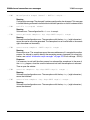
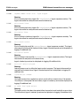
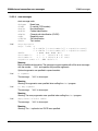
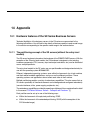
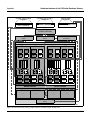
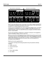
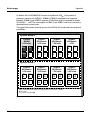
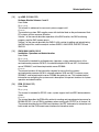
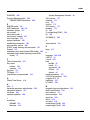
Figure 1: Example of an SX server: SX150 Business Server
On the business servers in the SX series suitable redundancy facilities result from the
operation of several partitions. These facilities are explained in more detail in the manual
“SX Series Business Servers – Concepts and Functions” [1].
Moreover, almost all functional elements can optionally be designed and configured redundantly on an SX server (console interfaces, disks, power supply, peripherals, etc.).
Business servers in the SX series have the following partitions according to the operating
system being run:
●
BS2000 partitions
The BS2000/OSD operating system is installed with the X2000 carrier system. X2000
is based on Solaris and essentially provides the runtime environment for BS2000/OSD.
As an alternative to the native operation of BS2000/OSD, depending on the model up
to 15 independent BS2000/OSD guest systems can be operated under VM2000.
●
Solaris partitions
The Solaris operating system is installed.
Each partition can be set up either on the basis of the physical partitioning PPAR or on the
basis of the extended partitioning XPAR. You will find more details on this in the appendix
(page 385ff).
2
U41272-J-Z385-3-76
Preface
X2000 is based on the Solaris operating system and provides the following functions:
●
HAL (Hardware Abstraction Layer)
HAL maps the hardware-software interfaces of the /390 mode to equivalent interfaces
of the SPARC64 mode.
●
/390 firmware
The /390 firmware component extends the SPARC64 mode and enables existing
customer applications to run object-compatibly on the SX servers under OSD/XC. This
applies both for applications generated with ASSEMBH and also for programs which
were generated with the BS2000 compilers for high-level programming languages. As
of OSD/XC V2.0 and X2000 V3.0A05 the SX servers also support ESA data spaces in
customer applications. Objects which are available in the special RISC object format for
SR2000 must be recompiled. The commands supported by ASSEMBH are described
in the manual “Assembler Instructions (BS2000/OSD)” [16].
●
Execution of the inputs/outputs and data communication
●
Administration and operation of the SX server
Entry-level models in the SX series
The entry-level models in the SX series are non-partitionable and designed for use exclusively with the BS2000/OSD operating system. BS2000/OSD running on entry-level models
uses the functionality of the X2000 carrier system.
With these models, too, state-of-the-art processor technology, the efficient LTO tape device,
and optional fibre channel connection technology for FibreCAT and Symmetrix disk systems
and for CentricStor and ITC/SBU with SAN integration capability make these servers a
future-safe investment.
You will find more detailed information on the hardware of the different model series in the
appendix (page 385ff).
U41272-J-Z385-3-76
3
Documentation for the SX Series Business Servers
Preface
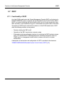
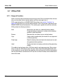
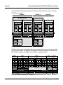
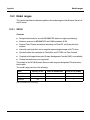
1.1 Documentation for the SX Series Business Servers
Extensive documentation is available to help you in your work with SX servers. It can be
ordered in printed form as a documentation package.
Its exact composition can be found in the Release Notice for OSD/XC.
The following manuals have been published specifically for the SX server series:
●
SX Series Business Servers
Concepts and Functions
User Guide
This manual provides an overview of the features and special characteristics of the
SX server. It also provides information concerning the OSD/XC-based extensions to
BS2000/OSD.
●
Operating Manuals for the SX Servers
These manuals describe the particular SX server and its hardware components.
They also provide information on hardware operation.
●
SX Series Business Servers
Operation and Administration
User Guide
This manual contains all the information necessary to operate an SX server. It includes
information on configuring the system together with a description of important functions
for its operation and administration.
4
U41272-J-Z385-3-76
Preface
Documentation for the SX Series Business Servers
●
OSD/XC
Performance Guidelines
User Guide
This manual focuses on the principles and measurements involved in evaluating the
performance of BS2000/OSD applications which run on SX servers. The performancerelated characteristics of the SX server architecture are described together with the
underlying operating sequences. Extensive information on tuning the configuration and
the software make it possible to optimize the economic efficiency of OSD/XC operation.
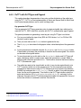
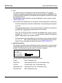
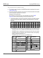
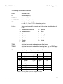
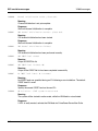
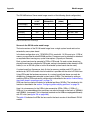
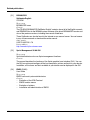
SX Series
Concepts and
Functions
SX100
Betriebsanleitung
SX130
Betriebsanleitung
SX140
Betriebsanleitung
SX150
User Guide
SX Series
Operating and
Administration
OSD/XC
Performance
Guidelines
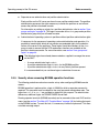
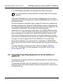
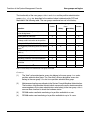
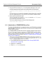
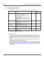
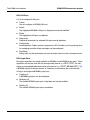
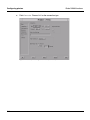
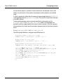
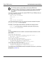
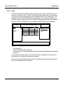
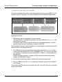
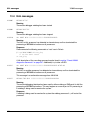
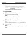
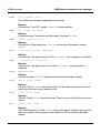
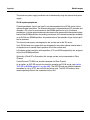
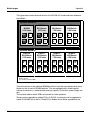
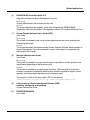
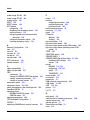
Figure 2: Structure of the documentation for the SX Series Business Servers
The core literature for the SX Series Business Servers in the BS2000 environment
consists of:
●
the manuals for the BS2000/OSD-BC V6.0 basic configuration
●
the manuals for the shipped versions of OSD/XC software products
●
the manuals for the current versions of system-related software products which can be
purchased separately
U41272-J-Z385-3-76
5
Documentation for the SX Series Business Servers
Preface
The following manuals in the core literature have been extended or replaced for OSD/XC:
Manual
Comment
BS2000/OSD-BC
Performance Handbook
Replaced by:
OSD/XC Performance Guidelines
BS2000/OSD-BC
System Exits
Only valid in connection with Special Release
i
The “OSD/XC Migration Guide” will be discontinued. As of the edition of June 2005
migration to SX servers is described in the “BS2000/OSD-BC Migration Guide” [3].
Readme files
For information on any functional changes or extensions, please refer to the Readme file for
the BS2000/OSD-BC V6.0 basic configuration or the product-specific Readme files for the
various software products:
SYSRME.<product>.<version>.E
Examples
SYSRME.BS2CP.060.D (BS2000/OSD-BC V6.0)
SYSRME.PERCON.028.D (PERCON V2.8)
Please refer to the appropriate system administrator for the user ID under which the
required Readme file can be found. You can also obtain the path name of the Readme file
directly by entering the following IMON command:
/SHOW-INSTALLATION-PATH INSTALLATION-UNIT=<product>, LOGICAL-ID=SYSRME.E
You can view the Readme file with/SHOW-FILE or by opening it in an editor or print it at a
standard printer using the following command:
/PRINT-DOCUMENT $<userid>.SYSRME.<product>.<version>.E,
LINE-SPACING=*BY-EBCDIC-CONTROL
Additional literature, in particular for the PRIMEPOWER servers and the products in the
Solaris environment, is available to complement the SX server documentation.
6
U41272-J-Z385-3-76
Preface
Target groups
1.2 Target groups
This manual is intended for privileged users (operators, system administrators) of the
SX series business servers. It is assumed that readers possess a thorough understanding
of the operating system and the hardware and have a basic knowledge of the graphical user
interface PRIMEPOWER ServerView.
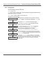
1.3 Summary of contents
You will find general information on the operation of an SX server in the chapter “Operating
concept of the SX servers”. This information includes:
–
–
–
–
–
–
–
Operating concept for SX servers with the System Management Console (SMC)
Operating concept for SX server entry-level models
Remote operation of each LAN PC
Notes on security for SX servers with SMC
Remote Service (Teleservice)
Procedures for switching the server (with SMC) on/off
Procedures for switching the server (entry-level models) on/off
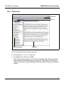
The chapter “Functions of the Solaris-CDE interface” describes the X-window interface
CDE (Common Desktop Environment) for controlling the SMC (System Management
Console).
The chapter “Functions of the System Management Console” explains the hardware
operation of the server and administration of the partitions.
The chapter “Functions of the SX server entry-level models” describes the switching on/off
functions, the integrated console, an optional LAN console and the time cluster with
external time servers for the entry-level models in the SX series.
The chapter “Remote operation via PC” discusses the recommended hardware and
software configuration and gives instructions on the configuration and operation of the
recommended software.
The chapter “Operating BS2000 instances” describes the operation of the BS2000 console
and dialog, as well as the event mode.
The chapter “The X2000 user interface” provides an overview of the functions of the X2000
interface provided in PRIMEPOWER ServerView. For details on individual menus and
dialog boxes refer to the online help.
The chapter “Global X2000 functions” describes the configuration of the SX server in
PRIMEPOWER ServerView.
U41272-J-Z385-3-76
7
Summary of contents
Preface
The chapter “Dynamic Reconfiguration” describes how Dynamic Reconfiguration can be
performed for BS2000 partitions and the requirements for this. This function is available on
SX servers as of the SX150 model series.
The chapter “Solaris: system administration” gives an overview of the system administration
in Solaris with reference to one or two examples.
The chapters “What if ...” and “X2000 messages” contain information on the detection and
removal of faults.
The appendix provides information on the hardware properties of the business servers in
the SX series and on the optional SKP-SR for BS2000 operation.
This is followed by a list of abbreviations and figures, the related publications and an index.
8
U41272-J-Z385-3-76
Preface
Notational conventions
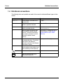
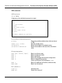
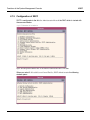
1.4 Notational conventions
The following fonts and symbols are used in this manual to indicate different types of information:
Font/Symbol
Indicates
Example
AaBbCc123
System outputs are written in this
typewriter font.
RC2000%
AaBbCc123
Commands entered by the user are
written in typewriter font bold
# ls -l <Return>
Italic text
Program interface functions and
menus are written like this.
Select the menu
Edit local parameters
“”
Manual, chapter and section titles
are enclosed by double inverted
commas. The names of positions,
keys, buttons and menus are also
enclosed in double inverted
commas.
See chapter 3, “Configuration of the
System Console“, in the “System
Console Software User’s Guide
(SCS)“ [7].
[ ... ]
Square brackets indicate a reference see “Migration Guide“ [3].
to related publications. The full title
and details of the reference
document are given in the “Related
Publications” section.
Ê
The enter symbol indicates an action Ê
that the operator must perform (e.g.
enter something on the keyboard).
!
i
U41272-J-Z385-3-76
Click the button VConfig.
Indicates warnings.
Indicates important information
about product operation.
9
Notational conventions
10
Preface
U41272-J-Z385-3-76
2 Operating concept of the SX servers
SX servers (with the exception of entry-level models) are operated via the system
management console (SMC) as the central console for the hardware and for the BS2000
and – optionally – Solaris operating systems. The business servers of the SX series, with
the exception of the entry-level models, are therefore also referred to in the following as
“SX servers with SMC”.
A concept has been developed for uniform operation of the different operating systems. This
operation is described in the section “Operating concept for SX servers with SMC” on
page 12.
The entry-level models in the SX series are also operated centrally with the integrated
console or an optional LAN console. For operating the entry-level models see the section
“Remote operation via LAN-PC” on page 16.
Remote administration can be performed from PCs separate from the computer center.
These can be used to administer the server and to configure and operate the instances of
BS2000 (e.g. remote BS2000 console) and, optionally Solaris, on the basis of a uniform
concept.
U41272-J-Z385-3-76
11
Operating concept for SX servers with SMC
Operating concept of the SX servers
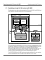
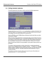
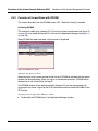
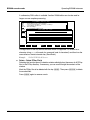
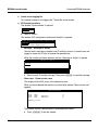
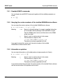
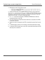
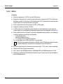
2.1 Operating concept for SX servers with SMC
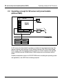
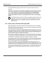
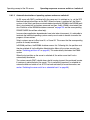
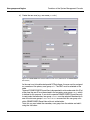
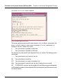
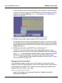
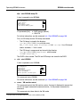
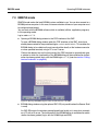
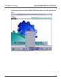
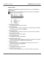
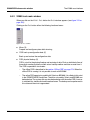
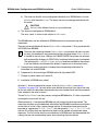
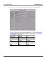
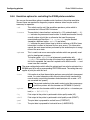
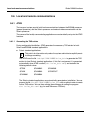
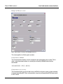
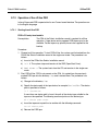
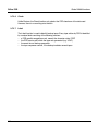
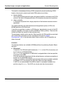
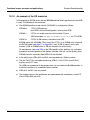
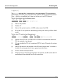
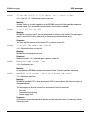
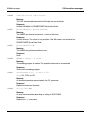
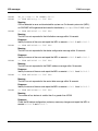
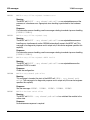
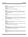
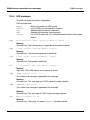
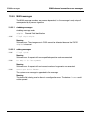
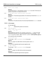
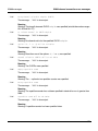
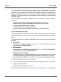
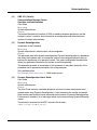
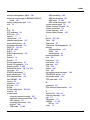
The figure below shows the operating concept of an SX server with SMC and a BS2000 and
Solaris partition, taking the example of an SX130 configuration:
System cabinet
SX1xx
Server
BS2000 partition
BS2000/OSD
(OSD/XC)
Solaris partition
Solaris
X2000
User LAN
CCU
Modem
SCF
Switch
Switch
Router
Admin LAN
System Control LAN
TeleserviceGate V.24
PC
System Management Console
(SMC)
Browser
Exceed
SINIX-TE
(optional)
9750 Emulation
(optional)
Figure 3: Example of an operating concept for an SX server
Up to and including SX140 the SMC for an SX server is based on a PRIMESTATION system
with Solaris 8. The SMC for an SX150 server is based on a PRIMEPOWER250 system with
Solaris 9. The user interface for all functions is the X-Window Common Desktop
Environment (CDE) interface. This is where the System Console Software (SCS) runs. This
is used to administer the hardware functions of the SX system, and in particular the
functions for starting up/shutting down the server and partitioning the system.
The DVD/CD-ROM drive of the SMC can be used across partitions. In this way, operating
systems and applications can be installed in every partition of the SX server.
12
U41272-J-Z385-3-76
Operating concept of the SX servers
Operating concept for SX servers with SMC
System administration of X2000 functions (and optionally, Solaris functions) can be
performed from any client via the PRIMEPOWER ServerView graphical user interface. To
do this, you will need a Web browser which has Java support. The SMC server names and
the names of all the partitions present on the SX server must be entered in the DNS. The
PRIMEPOWER ServerView application Domain makes it possible to perform administration
tasks outside of the local system. This means that administrators can administer clusters of
systems as a single system. So it is not necessary to perform each action for every system
individually and helps avoid errors.
The Domain application can support multiple BS2000/OSD instances and Solaris partitions
in a single PRIMEPOWER ServerView session.
The BS2000 console and dialog can be operated in the dtterm terminal emulation mode of
the X-Window CDE interface. The X2000 applications KVP software and 9750 emulation
provide the necessary functionality.
The individual SMC functions are described in detail in chapter “Functions of the System
Management Console” on page 43ff.
U41272-J-Z385-3-76
13
SX server entry-level models (without SMC)
Operating concept of the SX servers
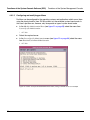
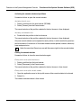
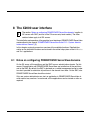
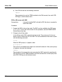
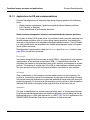
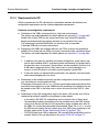
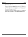
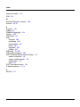
2.2 Operating concept for SX server entry-level models
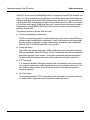
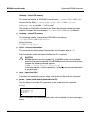
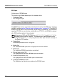
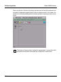
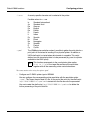
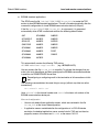
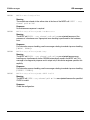
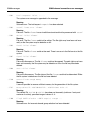
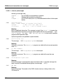
(without SMC)
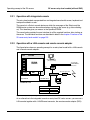
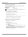
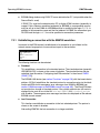
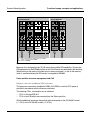
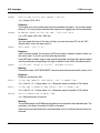
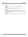
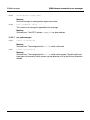
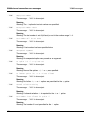
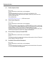
SX100
PCI
Integrated console
BS2000
OSD/XC
LAN
BS2000 ZASLAN
DAT
hme0
Teleservicegate V24
DVD
Modem
SOLARIS / X2000
Customer LAN
PC
X-Server
Browser
SINIX-TE
opt. 9750-Emu.
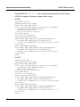
Figure 4: Operating concept of an SX server without SMC
An SX server entry-level model is operated as standard via the integrated console. The
operator interface for all functions is the X-Window interface CDE of the Solaris/X2000
carrier system. Here the interface provides functions for all the instances to be operated,
such as BS2000 console, BS2000 dialog, X2000 configuration and hardware administration.
Hardware components consist of a DVD/CD ROM drive for installing the operating system
and applications, and a DAT drive for backup purposes.
14
U41272-J-Z385-3-76
Operating concept of the SX servers
SX server entry-level models (without SMC)
2.2.1 Operation with integrated console
The entry-level models are operated from an integrated console with screen, keyboard and
touchpad installed in a rack.
The console is a Solaris console device on which the messages of the Solaris and the
X2000 carrier system can be monitored when starting up the server (e.g. after switching
on). This therefore gives you access to the OpenBoot PROM.
The console also provides the user interface for all the required functions after starting up
the server. The individual functions are described in detail in the chapter “Functions of the
SX server entry-level models” on page 125.
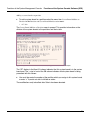
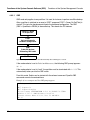
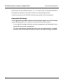
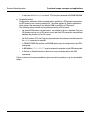
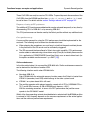
2.2.2 Operation with a LAN console and remote console adapter
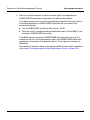
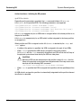
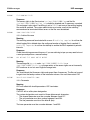
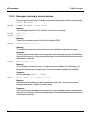
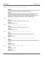
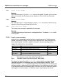
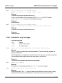
The figure below shows an operating concept for an entry-level model with a LAN console
and a remote console adapter:
PCI
SX100
Integrated Console
(except operation)
BS2000
OSD/XC
other SX100-/
PRIMEPOWER-/
RM servers
V24
tty a
RCA
LAN
BS2000 ZASLAN
DAT
Teleservicegate V24
hme0
DVD
LAN Console
Modem
SOLARIS / X2000
Customer LAN
PC
X-Server
Browser
SINIX-TE
opt. 9750-Emu.
Figure 5: Example of an operating concept for an entry-level model
As an alternative to the integrated console on entry-level SX series servers, you can use a
LAN console together with a V24/Ethernet converter, the remote console adapter (RCA).
U41272-J-Z385-3-76
15
Remote operation via LAN-PC
Operating concept of the SX servers
The LAN console is available for administering UNIX/Solaris midrange servers and
SX server entry-level models from Fujitsu Siemens Computers Gmbh. The LAN console
has the following features:
●
It supports the installation, configuration, administration and diagnostics management
of one or more connected SX server entry-level models, RM servers and
PRIMEPOWER servers.
●
The LAN console can be used to perform all the functions of a character-orientated
screen, including the OBP monitor and a reboot of the system.
●
The selection and display of one or more consoles of SX, RM and PRIMEPOWER
servers are performed by the tool xscon.
●
Support of PRIMEPOWER ServerView (Web-based system administration).
●
The SX server entry-level models and RM and PRIMEPOWER servers can also be
booted remotely (via LAN).
●
The Teleservice connection for all systems is available centrally on the LAN console.
2.3 Remote operation via LAN-PC
If remote operation of the SX server is required, it is possible to use PCs with a network
connection to the server's SMC.
If an X server is employed, then it is possible to make use of the SMC user interface. This
means that it is possible to access the System Console Software (SCS) using the same
interface as is available directly at the SMC.
Administration of the SX business server partitions using PRIMEPOWER ServerView is
possible either by calling PRIMEPOWER ServerView in the CDE user interface, via the
Start button, via an icon on the desktop, or directly in the PC's browser. The BS2000
console and dialog can be operated in the SMC dtterm windows.
Alternatively, SINIX-TE can be used as a 97801 emulation in order to provide support for
Fujitsu-Siemens emulation keyboards for BS2000 (this is not possible when establishing a
communication using the Secure Shell).
If an SKP-SR is present, then this can also be used to provide support for 97801 emulations
for BS2000 console and dialog access (this is only released on SX130 servers but cannot
be used for communication when the Secure Shell is employed).
For further information on hardware and software requirements as well as on configuration,
refer to chapter “Remote operation via PC” on page 133ff.
16
U41272-J-Z385-3-76
Operating concept of the SX servers
Notes on security
2.4 Notes on security
With an SX business server you can connect multiple systems to each other to form an
operating cluster. Entry-level models in addition to the operating system BS2000/OSD now
have the carrier system X2000 available as an additional system. This means that for
administration and operating purposes you will require access to a number of different
logins. The access to these logins (and in particular to the root login) has security-related
implications. The sections below provide some notes on access control.
2.4.1 Passwords
The business servers in the SX series are shipped with standard passwords for access to
the X2000 carrier system, Solaris (in the case of Solaris partitions) and the SMC.
These passwords must be changed by the customer, particularly for the root logins
on the corresponding systems!
i
When assigning passwords, we recommend that you follow these general rules:
–
–
–
Passwords must be changed at regular intervals.
Passwords can contain characters, figures and special characters.
Passwords must not be stored on the system or on the remote workstations.
2.4.2 Login access to root in the partitions
In the SX business server as it is supplied, root access to the partitions is possible only via
the console, either on the SMC (see section “Consoles of the partitions with RC2000” on
page 86) or, for entry-level models, on the local console.
In the system as supplied, a remote login to the root login via a network is therefore not
possible.
This is achieved by setting CONSOLE=/dev/console/ in the file /etc/default/login.
i
This entry must not be changed into a comment!
Generally speaking, it is not necessary to possess login access to the root login in order to
administer partition systems (of, for example, entry-level models) because PRIMEPOWER
ServerView is provided for this purpose. This is particularly true in the case of BS2000
systems.
U41272-J-Z385-3-76
17
Notes on security
Operating concept of the SX servers
However, should it become necessary to work under the root login then it is advisable to set
up user-specific logins under which login can be performed. Only then should the user
acquire root permissions by means of the su command.
User-specific IDs can be set up in the Users application of PRIMEPOWER ServerView in
the Users tab by clicking on the Users button and selecting the Create function (for details
please see the section “Administration of PRIMEPOWER ServerView” on page 53).
The advantage of this procedure is that root requests are logged in the sulog file. This
ensures that there is a record of when which users have acquired root permissions.
2.4.3 FTP access to root
This is similar to login access. File transfer with root permissions also calls for certain
security-related considerations. For this reason, FTP access to root is not possible by
default. This is achieved by setting root in the file /etc/ftpusers.
i
This entry must not be changed into a comment!
It is better to start by performing the transfer under a user-specific login. As described
above, the files can then be copied to the target location by using the su command with the
appropriate authorizations to request the root permissions.
2.4.4 User roles for SX servers with SMC
Depending on the extent to which it is necessary to separate Solaris and BS2000 administration and operation, there are a number of different ways of performing these tasks.
A number of related scenarios are presented below:
●
Joint administration of the server, the configuration and operation by system administration
In the simplest case all the server administration tasks are performed by a restricted
user group. In this case, all the members of this user group are able to access the SMC
from where they perform all the necessary tasks.
The SMC is not accessed via the root login but under one or more server administrator
logins belonging to the cladmin group (see section “User groups and logins” on
page 44).
18
U41272-J-Z385-3-76
Operating concept of the SX servers
Notes on security
Separate server administration and partition administration
●
Each partition on the SX server can have its own partition administrator. The partition
administrator possesses the rights necessary to switch the partition on and off and
access the partition's hardware console.
For information on setting up a login for a partition administrator, refer to section “User
groups and logins” on page 44. This login is a member of the clmon group and a partition
administrator group that you will need to create.
Administration of operating systems in partitions without partition administration rights
●
If necessary for the purposes of operating system administration and operation, it is
possible to create logins which do not possess any extended rights for the administration of the server or the partitions. These logins should be members of the clmon
group in order to ensure that the SCS read access functions are available at the
partition's hardware console. For more information, see section “User groups and
logins” on page 44.
i
The following logins have already been created as supplied to manage the server
on the SMC:
–
–
–
A server administrator login sxadmin
A partition administrator login bs2admin for the BS2000 partition
A partition administrator login soladmin for any Solaris partitions present
It is recommended that you use these logins to administer the server.
2.4.5 Security when accessing BS2000 operation functions
The following protective mechanisms can be set up when configuring BS2000 console
access:
BS2000 operation is performed via a login in X2000 for which a separate password is
required. This password must be subject to the usual password maintenance rules. The
logins from cons0 to cons7 are provided as default for this purpose. The administrator
defines any additional logins via PRIMEPOWER ServerView.
Running operator terminals (BS2000 consoles) can be secured via the main KVP function
menu (see the section “The Main KVP Function Menu” on page 164) by locking the inputs
on the BS2000 system. To reset this lock, it is necessary to enter the password. This does
not affect message output.
U41272-J-Z385-3-76
19
Notes on security
Operating concept of the SX servers
To connect additional operator terminals via LAN, it is always necessary to enter a
password.
All the inputs and outputs can be recorded in a logging file and then archived. In the case
of high security requirements, the option for both logging and archiving should be set to
FORCED. These settings are made in the Bs2Devices application of PRIMEPOWER
ServerView by clicking on the BS2-KVP tab, selecting the first entry for a KVP name,
clicking with the right mouse button, and selecting the function “Show or modify logging
options”.
i
Activating these options also has the effect of recording all inputs and outputs in the
logging file. This results in an increase in the size of the logging file. You should
therefore check the size of the logging files and free space in the file system at
regular intervals.
2.4.6 Secure access with Secure Shell (open SSH)
Where tight security for the remote operation of SX series business servers is specified,
Secure Shell (SSH) is an ideal solution for secure remote logins, executing commands, and
file transfers for administration purposes.
The most commonly used and most widespread application of Secure Shell is the secure
remote administration of servers in business networks. The Secure Shell protocol is used
worldwide on innumerable systems and Secure Shell technology has been developed as a
de facto standard in the area of application connection.
Secure Shell is an application which protects TCP/IP connections between two computers.
The connection is coded on the application layer, which means that the security provided
by Secure Shell is independent of the type or speed of the network connection.
In the business servers in the SX series Secure Shell is used for the connection between
the administration PC and the system management console (or the server directly in the
case of the entry-level models) and also the partitions.
The product OpenSSH is used on the BS2000 partitions, the Solaris partitions with a
Solaris version up to and including V8, and the SMC of the partionable servers up to and
including SX140. The Secure Shell Software from Sun which is integrated into Solaris from
V9 on is used on Solaris partitions with a Solaris version as of V9, and the SMC as of the
SX150 model series. Both products support both Version 1 and Version 2 of the SSH
protocol.
20
U41272-J-Z385-3-76
Operating concept of the SX servers
Notes on security
If the SSH is to be used on the BS2000 partition (i.e. the product OpenSSH is installed), the
rlogin, rsh, rcp, ftp and telnet services offered on the LAN are deactivated automatically and
they are replaced by the equivalent SSH interfaces ssh, scp and sftp. In this case the hostand ID-specific SSH configuration files (both in the partitions and on the SMC) are included
in the system data backup; X2000 itself then uses a secure transfer mechanism based on
DomainAdmin of the PRIMEPOWER ServerView Suite for communication between the
partitions and the SMC.
The following features of Secure Shell are used:
●
Powerful authentication mechanisms
With the asymmetrical process for private/public keys at host and user level SSH incorporates powerful authentication mechanisms. Here the private keys can be protected
by pass phrases. Integration into other authentication procedures such as Kerberos,
SecurID, PGP, TIS Gauntlet and PAM is also possible.
●
Strong encryption
Open SSH uses, among other things, 3DES and Blowfish as the encryption algorithms.
Both are unpatented. Here SSH Version 2 offers considerably more and more powerful
encryption algorithms than Version 1. Encryption commences before authentication.
No passwords, private keys, commands or user data are transmitted in plain text.
●
X11 Forwarding
X11 forwarding enables X-Windows network traffic to be coded in such a way that no
one is able to read the data traffic simultaneously or slip in malicious commands. The
data traffic for administration of the SX servers as part of the operating concept is
therefore protected.
●
Port Forwarding
Port forwarding enables TCP/IP connections to be forwarded to a remote machine via
a coded protocol. Applications can therefore be made more secure.
U41272-J-Z385-3-76
21
Remote service (Teleservice)
Operating concept of the SX servers
Components of the SSH
The SSH suite comprises the client program ssh which replaces rlogin, rsh and telnet,
Secure Copy scp which replaces rcp, and the Secure File Transfer Programm sftp which
replaces ftp. The client program ssh is used to set up a connection to a remote system
and to execute commands on a remote system.
The SSH suite also includes some administrative components such as the SSH daemon
sshd on the server side, the ssh-keygen function for generating, administering, and
converting authentication keys for SSH, and the ssh-agent and ssh-add functions for
controlling the SSH authentication agent.
Specifications for these functions are available on the Internet (e.g. at the URL
http://www.openbsd.org/cgi-bin/man.cgi). The use of keys and of the authentication agent is described in detail in the section “Key management for Secure Shell” on
page 153.
For details on installation and configuration and the application and use of Secure Shell see
the section “Access with Secure Shell” on page 144.
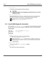
2.5 Remote service (Teleservice)
Teleservice gives you rapid access to the service staff and the service staff rapid, targeted
access to your system if this should be required.
Depending on the SX server specification, the Teleservice connection for all partitions is
centrally located on the SMC or, in the case of entry-level models, directly on the SX server
itself. This means that only one connecting line to the service center is required.
i
The Teleservice settings should only be made by a service engineer. The following
sections are therefore for information only.
The following are provided for Teleservice purposes:
22
●
An ISDN modem including the necessary cable connections
●
A power connection (230V)
●
The Teleservice software
●
The file transfer software
●
Teleservice Call Management and Remote Service 2000 for the BS2000 Teleservice
connection which is supplied together with X2000
U41272-J-Z385-3-76
Operating concept of the SX servers
Operating sequences on server switch-on / switch-off
An ISDN telephone connection is also required in the vicinity of the system.
●
i
If no ISDN connection can be provided then an analog modem must be ordered
separately.
Teleservice Call Management is a central instance in X2000 which makes it possible to
automatically report error messages from the Solaris/X2000/BS2000 area of a partition to
the Teleservice center.
The error messages are assembled in logs by Logging V3.0 and are then categorized by
message type and passed to Teleservice Call Management in the form of Teleservice calls.
This processes the messages before routing them on to Remote Service 2000 (rs2k). The
Remote Service 2000 transfers the messages to the Teleservice center.
Logging V3.0 has a user interface that can be called via the PRIMEPOWER ServerView
(System - Diagnostics button). By default, all the settings are configured in such a way that
the corresponding error messages can be selected and forwarded as Teleservice calls.
Teleservice Call Management does not possess its own user interface since no configuration measures are required from the user here. Any Teleservice Call Management error
messages are stored in Logging V3.0 with the ID SMAWLtsca in the module name.
Remote Service 2000 has a user interface which is not dependent on PRIMEPOWER
ServerView and which can be used to configure the settings for the transfer of Teleservice
calls.
For further information on Teleservice in Solaris, refer to the manuals “Teleservice
(Unix)” [31], “LAN Console or System Management Console (SMC)” [9] and “Solaris
System Diagnostics” [28].
2.6 Overview of operating sequences on server switch-on /
switch-off
This section gives an overview of the actions and operating sequences involved in switching
the SX server on and off.
The commands and actions refer to the operation of a variety of functions. These are
explained in detail in the individual chapters and here are simply listed in summary form as
a comprehension aid.
U41272-J-Z385-3-76
23
Operating sequences on server switch-on / switch-off
Operating concept of the SX servers
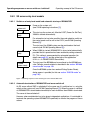
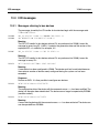
2.6.1 SX server with SMC
2.6.1.1
Switch-on of the SX server and automatic start-up of the operating systems
SMC
ready
●
Power on the server
(described in the SX1xx Operating Manual [2])
●
Start up the System Management Console (SMC)
(described in the SX1xx Operating Manual [2])
This automatically starts Solaris at the SMC as well as the System
Console Software.
●
Log in as server administrator sxadmin at the SMC (described in
section “User roles for SX servers with SMC” on page 18 and in
section “User groups and logins” on page 44).
Open the Machine Administration Menu and start up the server
(described in section “Machine Administration Menu” on page 58.
System unit
ready
This powers up the system unit. After the POST (Power On Self
Test), the Solaris operating system and, in BS2000 partitions, X2000
are started automatically.
Solaris
ready
For automatic start-up to be possible, the mode selection switch at
the control panel must be set to LOCK (see SX1xx Operating
Manual [2])
X2000
ready
The start-up of the X2000 and Solaris systems can be monitored at
the RC2000 consoles (for more information, see section “Consoles
of the partitions with RC2000” on page 86).
BS2000
System ready
●
When X2000 is started, BS2000 OSD/XC is also started
automatically provided that this operation has been enabled by
setting automatic IPL. This setting is recommended for automated
operation (for more information, see page 215 and the online help
system for BS2Devices in PRIMEPOWER ServerView).
BS2000 start-up can be monitored at the BS2000 console. For
information on calling a console window, see section “BS2000
console mode” on page 159.
Once the BS2000 system has reached Dialog-System-Ready,
dialog access is possible (for more information, see section
“EM9750 mode” on page 182).
Figure 6: Operating sequences when switching the SX server on/off
24
U41272-J-Z385-3-76
Operating concept of the SX servers
2.6.1.2
Operating sequences on server switch-on / switch-off
Automatic termination of operating systems and server switch-off
An SX server with SMC is switched off in the same way it is switched on, i.e. via the SCS
Machine Administration Menu on the SMC. When the server is switched off, the Solaris
systems in the Solaris partitions are terminated automatically, BS2000 in the BS2000 partitions is terminated with a shutdown command and then, finally, X2000 is terminated (see
also “Definition of the BS2000 shutdown command” on page 216 and the corresponding
PRIMEPOWER ServerView online help).
In cases where application dependencies have to be taken into account, it is advisable to
terminate the individual operating systems one-by-one in order to be able to monitor the
progress of these actions.
Solaris systems are set to Run-Level 5, i.e. Power Off. This means that the corresponding
partition is already terminated.
In BS2000 partitions, the BS2000 shutdown occurs first. Following this, the partition must
then be switched off via the Machine Administration Menu at the system console (see
section “Switching partitions off” on page 65). This automatically terminates the X2000
system.
When the last partition on the server is switched off, the entire server itself is also
automatically terminated.
The system console (SMC) should always be left running to permit the continued (remote
if necessary) administration of the server. This is particularly important if a schedule for
automatic switch-on/switch-off via APCS has been activated (for more information, see
section “Switching the server on/off on a scheduled basis” on page 66).
U41272-J-Z385-3-76
25
Operating sequences on server switch-on / switch-off
Operating concept of the SX servers
2.6.2 SX server entry-level models
2.6.2.1
Switch-on of entry-level model and automatic start-up of BS2000/OSD
Power on of
system unit
●
Power on the system unit
(see SX100 operating instructions [2])
System unit
ready
●
This starts up the system unit. After the POST (Power On Self Test),
X2000 is started automatically.
For automatic start-up to be possible, the mode selection switch on
the control panel must be set to the LOCK (see SX100 Operating
Manual [2]).
The start-up of the X2000 system can be monitored on the local
console (see SX100 Operating Manual [2]).
X2000
ready
BS2000
System ready
●
When X2000 is started, BS2000/OSD is also started automatically
provided that this operation has been enabled by setting automatic
IPL. This setting is recommended for automated operation (for
details see page 215 and the online help of the application
BS2Devices in PRIMEPOWER ServerView).
●
The start-up of the BS2000 can be monitored on the BS2000 console. Calling a console window is described in the section “BS2000
console mode” on page 159.
Once the BS2000 system has reached Dialog-System-Ready,
dialog access is possible (for this see section “EM9750 mode” on
page 182).
Figure 7: Operating sequences when switching SX server without SMC on/off
2.6.2.2
Automatic termination of BS2000/OSD and server switch-off
An SX server without SMC is switched off in the same way it is switched on, i.e. using the
switch on the system unit (see SX100 Operating Manual [2]). When the server is switched
off, BS2000/OSD is terminated automatically for each shutdown, then X2000 is terminated.
The server is then switched off.
However, when consideration has to be given to dependent applications, it is advisable to
terminate the operating system BS2000/OSD specifically to monitor the progress of these
actions.
26
U41272-J-Z385-3-76
3 Functions of the Solaris-CDE interface
The business servers in the SX series are operated from the console of the server with the
Solaris user interface. This user interface is called Common Desktop Environment – abbreviated to CDE. Here, the interface provides not only functions for operating Solaris (or the
X2000 carrier system) but is also used for operating BS2000 instances. Details on
operation are given in the following section.
Here the console of the corresponding SX server can be either the system management
console (SMC) or, in the case of the SX series entry-level models, the local console of the
server or a LAN console. Since the commands for calling the functions are different for the
SMC/LAN console and local console, they are listed separately in the following sections.
In addition to the consoles, the CDE interface can also be operated remotely from
administration PCs (see chapter “Remote operation via PC” on page 133).
U41272-J-Z385-3-76
27
CDE interface
Functions of the Solaris-CDE interface
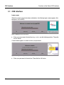
3.1 CDE interface
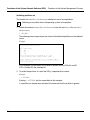
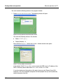
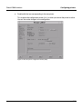
Login screen
When the system console has been switched on, the following login screen appears (this
example is for the SMC):
Figure 8: CDE login screen (user name)
Ê
Enter your user name in the text box (e.g. sxadmin; see the following section). Then click
the OK button.
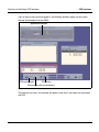
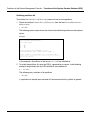
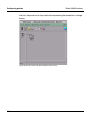
A new window appears in which to enter your password:
Figure 9: CDE login screen (password)
Ê
28
Enter your password in the text box. Then click the OK button.
U41272-J-Z385-3-76
Functions of the Solaris-CDE interface
CDE interface
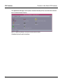
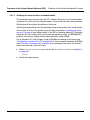
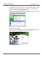
If this is the first time you have logged in, the following windows appear on the system
console (this example is for the SMC):
Application Manager
CDE control panel
SCS button
File manager with home directory
Figure 10: CDE window after the first login on a SMC
The next time you log in, the interface will appear in the form it was when you terminated
the CDE.
U41272-J-Z385-3-76
29
CDE interface
Functions of the Solaris-CDE interface
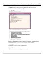
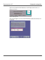
The Application Manager of the System Console Software (SCS) from which the functions
can be activated looks like this:
Figure 11: Application Manager of the System Console Software (SCS)
A double-click calls up the functions.
30
U41272-J-Z385-3-76
Functions of the Solaris-CDE interface
System administration of BS2000 and Solaris (optional)
3.2 System administration of BS2000 and Solaris (optional)
In the case of SX servers (not entry-level models) you must access the partitions in order
to be able to administer the operating systems in the individual partitions. This is provided
on the one hand by the consoles of the partitions supplied on the system management
console (SMC) of RC2000, and on the other by the network access of the SMC via the
administration LAN of the server.
In the case of the entry-level models, you access the partitions from the local console on
which you logged on directly to the system.
The administration of BS2000 systems requires access to the BS2000 console and a
BS2000 dialog access. Here access is provided via preconfigured X2000 user IDs in the
system.
For the sake of simplicity and increased operating security, the CDE user interface is
configured so that it is possible to call the individual instances at a mouse click.
This has already been done in the factory for the predefined user IDs sxadmin (server
administration of all the SX servers), bs2admin (BS2000 administration; not for the entrylevel models) and soladmin (Solaris administration; only if a Solaris partition is available).
In the case of the SX servers, except for the entry-level model, icons are set up on the SMC,
under these user IDs, for access to the Solaris partitions (only in the case of the identification sxadmin), for the BS2000 console, for the BS2000 dialog and for PRIMEPOWER
ServerView of the BS2000 partition. The functions for hardware administration are provided
by the system console software on the SMC (see chapter “Functions of the System
Management Console” on page 43).
In the case of the entry-level models, icons are set, under the user ID sxadmin, for access
to the BS2000 console, to the BS2000 dialog, to PRIMEPOWER ServerView and to the
hardware administration with the machine administration menu.
In the next section a description is given of how these CDE actions (e.g. for further userspecific IDs) can be set up or modified.
U41272-J-Z385-3-76
31
Preconfiguring terminals
Functions of the Solaris-CDE interface
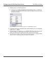
3.3 Preconfiguring terminals
The preconfiguration for accessing the individual functions is based on the creation of an
“action” in the CDE interface of the Solaris system on the SMC or on the X2000 carrier
system. An icon is assigned to a command sequence. The configured commands can be
called up via this icon simply and without a risk of operator error.
The icons can be stored in various places, for example, directly on the CDE desktop or on
the control panel of the CDE interface.
The basic procedures for creating this “action” and storing the relevant icon are described
first in an example for accessing a BS2000 console. Then a description of the commands
used to access the individual instances (Solaris shell, BS2000 console, etc.) is provided.
The CDE desktop provides the function Create Action for creating actions. This tool can be
called up either via the Application Manager in the subfolder Desktop_Apps or directly via the
context menu of the desktop (right-click on the desktop background: Workspace Menu ->
Tools -> Create Action).
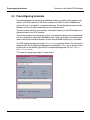
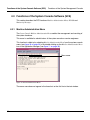
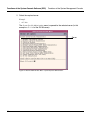
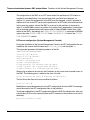
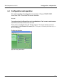
This opens the processing window “Create Action”:
Figure 12: “Create Action” window
32
U41272-J-Z385-3-76
Functions of the Solaris-CDE interface
Preconfiguring terminals
Three entries are important when creating an action:
–
–
–
The name of the action (subtitle of the icon)
The icon
The command which is triggered when the icon is activated (with a double-click)
These three entries must be entered in that order in the fields of the window Create Action.
Enter the name of the icon in the first input line Action Name (Icon Label). Use a name which
will enable you to clearly identify the action, for example, “BS2000 Console”, “BS2000
Dialog” or “Solaris Shell – Server sx150part2”.
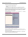
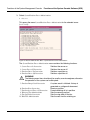
Select the appropriate icon from the section Action Icons. Click on Find Set… . This opens a
new window for selection:
Figure 13: Window for selecting an icon
All the icons available on the SMC are in the directory /usr/dt/appconfig/icons/C.
Select this line with a double-click. A selection list of all available icons then appears in the
right-hand side of the window.
For this example of accessing a BS2000 console, select the icon Dtterm, since terminal
emulation is to be started on the SMC with this action.
U41272-J-Z385-3-76
33
Preconfiguring terminals
Functions of the Solaris-CDE interface
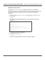
Confirm your selection with OK.
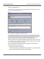
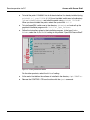
After returning to the main window, enter the actual command. Do this in the line Command
when Action is Opened (Double-clicked).
Example
Figure 14: Example for a command in the “Create Action” window
In the example for a BS2000 console, the command consists of calling up the terminal
emulation dtterm with parameters for the character set, the window title, the color settings
for the console and a command which is executed in the generated window. These
commands and parameters are explained in detail in the following sections.
When the command has been entered, the generated action must be saved. To do this, call
Save from the File> menu. The action is then saved in the home directory of the current login.
This is confirmed with an appropriate message.
Finally, the action which has just been created is integrated into the CDE interface.
The following options are available for this:
●
Store the action directly on the desktop
After the file manager has been opened with the home directory, you can drag and drop
the action which is there to copy it directly onto the desktop.
34
U41272-J-Z385-3-76
Functions of the Solaris-CDE interface
●
Preconfiguring terminals
Integrate the action into the CDE control panel
First create a new button in the CDE control panel to do this. Right-click on the position
at which the button is to be added. Select Add Icon from the context menu which is
displayed. An empty button is then created.
The button is assigned the action dragged onto it from the opened file manager with the
home directory.
If the button which has just been created is to be extended to include a menu (like most
other buttons on the CDE control panel), right-click on it to call the context menu again
and select Add Subpanel. A submenu is then displayed at the top of the checkbox with
the available action and an empty menu item (labeled "Install Icon"). Fill this empty
menu item by dragging and dropping the relevant action.
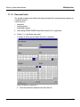
3.3.1 Parameters for configuring an action for a dtterm terminal emulation
The following actions for Solaris shell (not on entry-level models), BS2000 console and
BS2000 dialog are based on a dtterm terminal emulation call. This makes a window
available for actual access via further commands. Configuring a dtterm window is a very
flexible process and we will therefore first explain some of the possible parameters
concerned.
The terminal emulation is always called up by the command dtterm. If the path variable
has not been set correctly, it may be necessary to specify the absolute path
/usr/dt/bin/dtterm.
Parameters can be specified additively:
●
Assign a window title with -title "<title text>", e.g. -title "Solaris Shell
- Server SX150ABC" or -title "BS2000 Console".
●
Select a character set with -fn <font name>, e.g. -fn 9x15.
All fonts which are installed can be determined with the command xlsfonts.
●
Specify the terminal type with –tn <terminal type>, e.g. –tn bs2console.
Not only the previous color scheme, with output of the messages in a yellow color, but
also a color scheme adapted to the CDE, can be used when calling the console distribution program KVP for the BS2000 console. Here normal messages and inputs are
output in the foreground color (black), emergency messages and questions are output
as before in red, and KVP messages are underlined.
The terminal type bs2console must be set for using these color schemes.
U41272-J-Z385-3-76
35
Preconfiguring terminals
Functions of the Solaris-CDE interface
●
Select a background color with -bg <Name_of_background_color>,
e.g. -bg grey65.
●
This is particularly important with the BS2000 console if the terminal type bs2console
is not set, since the called BS2000 KVP program outputs the messages in yellow.
All colors that can be selected are listed in the file /usr/openwin/lib/X11/rgb.txt.
When selecting a color, ensure that all outputs remain legible.
The following colors are recommended for the BS2000 console, in addition to various
grays (grey65...70, DarkGrey): tan2, burlywood3, DarkKhaki, CadetBlue, PeachPuff3,
NavajoWhite3, SteelBlue2.
i
The general standard recommendation is the terminal type bs2console without
any special background color being specified.
3.3.2 Solaris shell (not on entry-level models)
To create a Solaris shell access to a partition, the following command must be entered when
creating the action if the Secure Shell is not used:
dtterm -e telnet <server name of the Solaris partition>
If the Secure Shell is used, the following command must be entered when creating the
action:
dtterm -e ssh <server name of the Solaris partition>
The call of the terminal emulation dtterm can be extended as described above to include
parameters for assigning a title text and selecting a character set or a background color.
Example without using the Secure Shell
dtterm -fn 9x15 -bg white -title "Solaris Shell - Server SX-ABC"
-e telnet sx-abc.
Example using the Secure Shell
dtterm -fn 9x15 -bg white -title "Solaris Shell - Server SX-ABC"
-e ssh sx-abc.
36
U41272-J-Z385-3-76
Functions of the Solaris-CDE interface
Preconfiguring terminals
3.3.3 BS2000 console
The ID cons0 mentioned in this section represents a predefined KVP ID. Here the
relevant KVP ID must be entered, according to the desired IPL console mnemonics
(for this see page 164).
i
SX servers without entry-level models
To create BS2000 console access to a partition, the following command must be entered
when creating the action if the Secure Shell is not used:
dtterm -tn bs2console -e rlogin <server name of BS2000 partition> -l cons0
If the Secure Shell is used, the following command must be entered when creating the
action:
dtterm -tn bs2console -e ssh <server name of BS2000 partition> -l cons0
The call to the terminal emulation dtterm can be extended as described above to include
parameters for assigning a title text and selecting a character set or a background color.
Example without using the Secure Shell
dtterm -fn 9x15 -tn bs2console -title "BS2000 console SX-BS2"
-e rlogin sx-bs2 -l cons0
Example using the Secure Shell
dtterm -fn 9x15 -tn bs2console -title "BS2000 console SX-BS2"
-e ssh sx-bs2 -l cons0
SX server entry-level models with the local console
To create a BS2000 dialog access to a partition, the following command must be entered
when creating the action:
dtterm –fn <font> –title "BS2000 console - <servername>" –tn bs2console -e sh
–c "exec login cons0"
Example
dtterm -fn 9x15 -title "BS2000 console – SX100" -tn bs2console -e sh –c
"exec login cons0"
U41272-J-Z385-3-76
37
Preconfiguring terminals
Functions of the Solaris-CDE interface
3.3.4 BS2000 dialog
SX servers without entry-level models
To create BS2000 dialog access to a partition, the following command must be entered
when creating the action if the Secure Shell is not used:
dtterm -e rlogin <server name of the BS2000 partition> -l em9750
If the Secure Shell is used, the following command must be entered when creating the
action:
dtterm -e ssh <server name of the BS2000 partition> -l em9750
The call to the terminal emulation dtterm can be extended as described above to include
parameters for assigning a title text and selecting a character set.
Example without using the Secure Shell
dtterm -fn 9x15 -title "BS2000 dialog" -e rlogin sx-bs2 -l em9750
Example using the Secure Shell
dtterm -fn 9x15 -title "BS2000 dialog" -e ssh sx-bs2 -l em9750
Details of setting up console accesses to the guest systems of a VM2000 system are
provided in the section "Operating the guest systems using operator terminals" in the
"VM2000 (BS2000/OSD)" [14] manual.
SX server entry-level models with local console
To create BS2000 dialog access to a partition, the following command must be entered
when creating the action:
dtterm -e sh –c "exec login em9750"
Example
dtterm -fn 9x15 -title "BS2000 dialog – SX100" -e sh –c "exec login
em9750"
38
U41272-J-Z385-3-76
Functions of the Solaris-CDE interface
Preconfiguring terminals
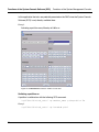
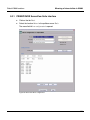
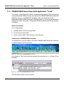
3.3.5 PRIMEPOWER ServerView (BS2000 system)
SX server (not entry-level models)
A CDE action can also be created to call PRIMEPOWER ServerView as an application. The
call should be made in the System Management Console.
When creating the action, select the icon “WSA” instead of the icon “Dtterm”.
The command to be entered should then be:
/opt/SMAW/bin/wsa `uname -n`
The command locally calls the PRIMEPOWER ServerView-application of the SMC.
SX server entry-level models with local console
To call PRIMEPOWER ServerView as an application in an entry server, you must call the
PRIMEPOWER ServerView program directly. Here the call is performed in the X2000
carrier system.
The following command must be entered in the CDE action:
/opt/SMAW/bin/wsa ’uname –n’
3.3.6 Machine Administration Menu (for entry-level models only)
In this case the functions for hardware administration, unlike those for SX servers with SMC,
are not integrated directly in the CDE interface. To call the machine administration menu
(see section “Displaying the configuration” on page 81) a further CDE action must therefore
be created for the entry-level models in the SX series. The machine administration menu
requires root rights, which is why the ID madmin is created with corresponding assignment
of rights. The ID madmin allows direct access to the relevant function.
The following command must be entered in the CDE action:
dtterm -e sh –c "exec login madmin"
In this case the calling of the terminal emulation can be supplemented as mentioned above
by parameters for assigning a title text and for selecting a character set.
Example
dtterm -fn 9x15 -title "MAdmin – SX100" -e sh –c "exec login madmin"
U41272-J-Z385-3-76
39
Calling terminal instances
Functions of the Solaris-CDE interface
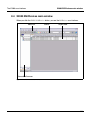
3.4 Calling terminal instances
The desktop generated in the previous section can have the following appearance:
Figure 15: Example of a desktop
The generated actions (e.g. BS2000 console) are called either by clicking on the button in the
CDE control panel or by activating the submenu of this button (click on the small arrow at
the top edge of the icon) and the clicking on the relevant entry.
When the BS2000 console, BS2000 dialog and Machine Administration Menu are called,
authorization is needed.
When using the password mechanism, the passwords which must be entered are those of
the relevant KVP ID (BS2000 console), the em9750 ID (BS2000 dialog) and the madmin ID
(for the Machine Administration Menu), respectively. When using the Secure Shell with a
key not protected by a pass phrase, no further specification is necessary at this place.
When using the Secure Shell with a key protected by a pass phrase the pass phrase must
be entered.
The windows which are opened are closed automatically by stopping the application
running in them. BS2000 consoles are stopped by entering ::c or [CTRL] [D] . A BS2000
dialog is stopped by logging the dialog off and then pressing the [F10] key and leaving the
em9750 emulation (with Exit). Terminate the Machine Administration Menu using the
q function (for Quit).
The windows can also be closed by clicking on the top-left corner of the window and
selecting the action Close from the context menu.
40
U41272-J-Z385-3-76
Functions of the Solaris-CDE interface
Calling terminal instances
If windows are opened during the current CDE session and the session is terminated with
EXIT, these windows will automatically be restarted when you next log in to the CDE
interface.
U41272-J-Z385-3-76
41
Calling terminal instances
42
Functions of the Solaris-CDE interface
U41272-J-Z385-3-76
4 Functions of the System Management Console
A PRIMEPOWER250 (up to and including SX140 a PRIMESTATION) is used on SX servers
(with the exception of entry-level models) as the System Management Console (SMC):
●
The SMC checks the hardware configuration and the operating status of the SX server.
●
The SMC partitions the resources and thus enables the processor and memory
capacities of the SX server to be shared.
●
The SMC supports partition-specific console displays.
●
The SMC supports a power supply scheduling system for switching the SX server or
individual partitions on it on and off at specific times.
●
The DVD/CD-ROM drive of the SMC can be used across partitions.
●
In this way, operating systems and applications can be installed in every partition of the
SX server.
●
The DAT drive of the SMC can be used across partitions (but usually only by service
technicians).
●
On every partition of the SX server, the time is synchronized with the time of the SMC
via the network time protocol (NTP).
●
The SMC monitors the entire hardware of the SX server.
●
If an error is detected, the relevant information is displayed on the SMC. The system
administrator can optionally be notified by e-mail.
●
The CDE interface (CDE = Common Desktop Environment) of the SMC allows access
to PRIMEPOWER ServerView (see section “Starting PRIMEPOWER ServerView
Suite” on page 196) and to BS2000 operation facilities (console, dialog; see section
“Calling terminal instances” on page 40).
This manual only describes functions which are absolutely necessary for operating the
SX server. Additional information is described in the latest version of “System Console
Software User’s Guide (SCS)” [7].
U41272-J-Z385-3-76
43
User groups and logins
Functions of the System Management Console
4.1 User groups and logins
The System Console Software supports a graded system of rights to manage the hardware
functions of the SX server.
The following sections describe how to set up logins for the various administrator roles
(server administrator, partition administrator, BS2000 or Solaris administrator, and also
administrator of PRIMEPOWER ServerView) with PRIMEPOWER ServerView and the
System Console Software (SCS). It is also possible to combine multiple administrator roles
in one user ID.
Both SCS and PRIMEPOWER ServerView require root authorization to perform these
setup processes.
As of PRIMEPOWER ServerView V2.2B access to applications in PRIMEPOWER
ServerView and access to nodes of the administration domain can be defined selectively
for a PRIMEPOWER ServerView administrator via a differentiated assignment of rights.
Details on this are provided in the section “Privilege concept with Role-Based Access
Control” on page 201ff.
System administrators work with the System Management Console to manage the server.
In addition, separate administrators can be defined for individual partitions that only have
access to the assigned partition. To manage BS2000 or Solaris in a partition, it is also
possible to define BS2000 or Solaris administrators who do not have rights for managing
the hardware of the server.
This section describes how to handle user logins for the following operating staff:
●
Server administrators
●
Partition administrators
●
BS2000 or Solaris administrators
●
PRIMEPOWER ServerView administrators
i
The SX server is shipped ready with the following user logins for managing the
server from the SMC:
–
–
–
A server administrator login sxadmin
A partition administrator login bs2admin for all the BS2000 partitions present
A partition administrator login soladmin for all the Solaris partitions that may be
present
It is recommended that you use these logins to manage the server.
44
U41272-J-Z385-3-76
Functions of the System Management Console
User groups and logins
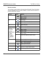
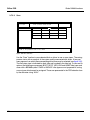
The functionality of the user groups cladmin and clmon and the partition administration
groups p0grp, p1grp, etc. described in the sections below is determined by SCS and
described in the following table. The user groups mentioned are set in the factory.
User group
cladmin
clmon
Adm(1)
Operation
cemainte
Non-Adm
(1)
Reference to monitoring messages and configuration dialog boxes
X
X
X
X
System power-on indication
X
-
-
X
Power-on instruction, shutdown instruction,
and dump switch instruction to the partition
X
X
-
X
Settings for Multiple-Partition Configuration
X
-
-
-
R/W (read/write) monitoring of the OS console
screen (3)
X
X
-
X
R/O (read-only) monitoring of the OS console
screen (4)
X
X
X
X
Saving crash dump data
X
X
-
-
Scheduling automatic mainframe operation
X
-
-
-
Viewing the automatic operation schedule of a
mainframe
X
X
X
X
Maintenance operation (2)
X
-
-
X
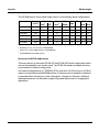
Table 1: Functionality of the administrator user group in the SCS
Comments
(1)
The “Adm” column designates users who belong to the user group clmon and a
partition administration group. The “Non-Adm” column designates users who
belong to the user group clmon but to no partition administration group.
(2)
Maintenance functions are offered via the System Console Machine Administration.
The functions of the Machine Administration are normally used by hardware maintenance engineers. But system administrators who belong to the user group cladmin
can use these functions to check the hardware status.
(3)
RC2000 makes read/write monitoring of a partition available for a user.
(4)
RC2000 makes read monitoring of a partition available for up to 14 users.
U41272-J-Z385-3-76
45
User groups and logins
Functions of the System Management Console
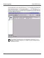
4.1.1 Server administrator
The administrator of the server manages the entire server and the system console.
The administrator has root access to the system console. This root authorization allows the
administrator to use all available functions of the SCS. For basic security reasons, however,
only the following actions should be performed:
–
–
–
–
Configuring the system console (generally this is not necessary since the console has
been configured ex works)
Adding, modifying and deleting partition administrators (where required)
Configuring the SMC as an installation server
Configuring and modifying server names for partitions
A login with the name sxadmin is configured by default for the server administrator. This login
is a member of the following user groups:
–
cladmin (a group defined by the System Console Software with administration authorization for the server).
Users in this group have administrative rights for all partitions of the server.
–
wsauser as secondary user group (a group for administering PRIMEPOWER
ServerView defined by PRIMEPOWER ServerView)
In the as-supplied status the sxadmin ID has read/write access for all applications of
PRIMEPOWER ServerView and for all nodes of the administration domain.
To configure further server administrator logins, the following actions are necessary:
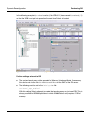
1. Set up the login with PRIMEPOWER ServerView in the user group cladmin:
a) Start PRIMEPOWER ServerView (see the section “Starting PRIMEPOWER
ServerView Suite” on page 196)
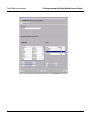
b) Select Applications -> Users from the menu bar
c) Select Users -> Create from the menu bar
46
U41272-J-Z385-3-76
Functions of the System Management Console
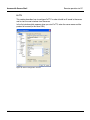
User groups and logins
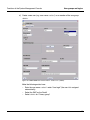
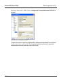
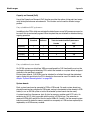
d) Create a new user (e.g. user name sxadmin1) as a member of the user group
cladmin:
Figure 16: PRIMEPOWER ServerView window: “Create user” (cladmin)
Make the following entries here:
–
–
–
U41272-J-Z385-3-76
Enter the user name sxadmin1 under “User login” (the user id is assigned
automatically)
Select the SMC as the “Node”
Select cladmin for “Primary group”
47
User groups and logins
–
–
–
Functions of the System Management Console
No entries are required in the “Supplementary groups” section for someone who
is exclusively an SX server administrator.
If PRIMEPOWER ServerView is also to be operated in write mode under this
user ID, wsauser must be selected as the secondary user group. The secondary
user group wsaruser must be selected for operation in read mode. Membership
in one of the two user groups wsauser or wsaruser also causes this user process
to run in PRIMEPOWER ServerView with root authorization.
Select a login shell.
A comment can be specified if necessary.
The home directory in Solaris (in this example /export/home/sxadmin1) is
created automatically.
e) As of PRIMEPOWER ServerView V2.2B the access rights of this user ID can be
defined more specifically with regard to access to applications in PRIMEPOWER
ServerView and access to nodes in the administration domain. Further details are
provided in the section “Privilege concept with Role-Based Access Control” on
page 201ff.
2. Set up the SCS user interface (Terminal in the Application Manager) for the server
administrator using the following command (which must be performed with root
authorization):
/opt/FJSVscsl/bin/scslowneradd -a <username>
The option -a here stands for “administrator”.
48
U41272-J-Z385-3-76
Functions of the System Management Console
User groups and logins
4.1.2 Partition administrators
Partition administrators also use the interface of the System Console Software to manage
the hardware of the partition. They have access to the hardware console of the partition
assigned to them and are authorized to switch the partition on/off. They do not have rights
to any other partitions.
Two partition administrator logins are configured by default for the two platform types:
●
bs2admin for all BS2000 partitions present
●
soladmin for all Solaris partitions that may be present
A login is configured for the partition administrator. This login is a member of the following
SMC user groups:
●
clmon (this is a group with monitoring rights for all partitions of the server)
●
In all partition administration groups which belong to the platform type concerned (each
group has administration rights for the partition assigned to it)
In addition the login is a member of the secondary user group wsauser which provides
authorization to administer PRIMEPOWER ServerView.
Partition administration groups correspond one-to-one to server partitions. A user registered in this group has the rights needed for managing the partition and can carry out input
and output operations on the RC2000 console of the partition.
In the as-supplied status a partition administrator login has read/write access to all applications of PRIMEPOWER ServerView of the nodes on the platform type concerned.
To configure further partition administrator logins, the following actions are necessary:
1. Configure the login with PRIMEPOWER ServerView in the user group clmon:
a) Start PRIMEPOWER ServerView (see the section “Starting PRIMEPOWER
ServerView Suite” on page 196)
b) Select Applications -> Users from the menu bar
c) Select Users -> Create from the menu bar
U41272-J-Z385-3-76
49
User groups and logins
Functions of the System Management Console
d) Create a new user (e.g. user name soladmin2) as a member of the user group clmon:
Figure 17: PRIMEPOWER ServerView window: “Create user” (clmon)
No entries are required in the “Supplementary groups” section for someone who is
exclusively an SX server administrator.
If PRIMEPOWER ServerView is also to be operated in write mode under this user
ID, wsauser must be selected as the secondary user group. The secondary user
group wsaruser must be selected for operation in read mode. Membership in one of
the two user groups wsauser or wsaruser also causes this user process to run in
PRIMEPOWER ServerView with root authorization.
As of PRIMEPOWER ServerView V2.2B the access rights of this user ID can be
defined more specifically with regard to access to applications in PRIMEPOWER
ServerView and access to nodes of the administration domain. Details on this can
be found in the section “Privilege concept with Role-Based Access Control” on
page 201ff.
50
U41272-J-Z385-3-76
Functions of the System Management Console
User groups and logins
2. If necessary, configure a further partition-specific user group with PRIMEPOWER
ServerView, e.g. part1grp.
i
User groups suitable for this have already been configured by default with the
name p0grp, p1grp, etc. and are used for the partition administrators bs2admin
and soladmin.
These groups can be used when configuring further partition administrators.
Alternatively, further user groups can also be created for this.
Click on the Groups tab and select Groups -> Create from the menu bar:
Figure 18: PRIMEPOWER ServerView window: “Create group”
3. Set up the SCS user interface (Terminal in the Application Manager) for the partition
administrator using the following command (which must be executed with root
authorization):
/opt/FJSVscsl/bin/scslowneradd -h <server name of partition>:<partition
administration group> <username>
The -h option here stands for partition administrator.
U41272-J-Z385-3-76
51
User groups and logins
Functions of the System Management Console
4.1.3 BS2000 or Solaris administrators
To manage the operating systems of individual partitions, it may be useful to configure user
IDs which do not have extended rights relating to the management of the hardware of the
server (like server administrators or partition administrators).
These user IDs must however be able to read the data of the RC2000 consoles of the partitions.
These IDs are also suitable for the administrator for preconfiguring terminals to access the
partitions (see also section “Preconfiguring terminals” on page 32).
The following actions are needed to configure a user ID of this type:
1. Set up the login with PRIMEPOWER ServerView in the user group clmon:
a) Start PRIMEPOWER ServerView (see the section “Starting PRIMEPOWER
ServerView Suite” on page 196)
b) Select the Users application
c) Select Users -> Create from the menu bar
d) Create a new user (e.g. user name bs2adm1) as a member of the user group clmon
No entries are required in the “Supplementary groups” section for someone who is
exclusively an SX server administrator.
If PRIMEPOWER ServerView is also to be operated in write mode under this user
ID, wsauser must be selected as the secondary user group. The secondary user
group wsaruser must be selected for operation in read mode. Membership in one of
the two user groups wsauser or wsaruser also causes this user process to run in
PRIMEPOWER ServerView with root authorization.
As of PRIMEPOWER ServerView V2.2B the access rights of this user ID can be
defined more specifically with regard to access to applications in PRIMEPOWER
ServerView and access to nodes of the administration domain. Details on this can
be found in the section “Privilege concept with Role-Based Access Control” on
page 201ff.
52
U41272-J-Z385-3-76
Functions of the System Management Console
User groups and logins
2. Set up the SCS user interface (Terminal in the Application Manager) for the user ID
using the following command (which must be executed with root authorization):
/opt/FJSVscsl/bin/scslowneradd -h <server name_of_partition>:clmon <user
name>
In the next step you must remove the assignment of administration rights to a partition
which was needed temporarily to set up the SCS user interface. Proceed as follows:
3. Remove partition administration rights
The entry generated by the command scslowneradd in the file /etc/FJSVclowners
must be removed using an editor (e.g. vi).
The line to be deleted comprises an entry with the following format:
clmon:<server name of partition>.
4.1.4 Administration of PRIMEPOWER ServerView
The actions described under item 1 are required to set up a user ID which has no extended
rights with regard to the hardware administration of the server and can be operated under
PRIMEPOWER ServerView.
As of PRIMEPOWER ServerView Suite V2.2B it is possible to define the access rights of
this user ID with regard to access to applications in PRIMEPOWER ServerView and the
access to nodes of the administration domain more precisely (see item 2 on page 55). The
information required for this is provided in the section “Privilege concept with Role-Based
Access Control” on page 201ff.
1. Setting up the user ID with PRIMEPOWER ServerView in the primary user group other
or in a user group defined by the user (a user group can be generated in the Groups tab
in the Users group by clicking on the Groups button):
a) Start PRIMEPOWER ServerView (see the section “Starting PRIMEPOWER
ServerView Suite” on page 196)
b) Select the Users application.
c) Select Users -> Create in the menu bar.
U41272-J-Z385-3-76
53
User groups and logins
Functions of the System Management Console
d) Create the new user (e.g. user name pwsvadm)
Figure 19: PRIMEPOWER ServerView window:”Create user” (administrator of PRIMEPOWER
ServerView)
As the user is not to be allocated special SCS privileges, the user must be assigned
as a member of the primary user group other. The SMC must be selected as the
node.
To permit PRIMEPOWER ServerView to be operated in write mode under this ID at
a later time the user ID must be entered in the secondary user group wsauser which
is defined for this purpose. If you wish to operate PRIMEPOWER ServerView only
in read mode, the secondary user group wsaruser must be selected. Membership in
one of the two user groups wsauser or wsaruser ensures that this user group runs
within PRIMEPOWER ServerView with root authorization
To do this you must select the secondary user group from the window and add it
using the Add button.
54
U41272-J-Z385-3-76
Functions of the System Management Console
User groups and logins
2. After this it may be necessary to adjust the access rights to the applications of
PRIMEPOWER ServerView and the nodes of the administration domain.
In the following cases such a user ID is automatically assigned the full access rights to
all available applications of PRIMEPOWER ServerView and to all nodes of the
administration domain:
●
Use of PRIMEPOWER ServerView Suite Version < V2.2B
●
When the user ID is created the feature Role Based Access Control (RBAC) is not
activated in PRIMEPOWER ServerView.
If the RBAC feature is activated in PRIMEPOWER ServerView when the user ID is
created, the user ID is not assigned access rights to the PRIMEPOWER ServerView
applications or the nodes of the application domain. These rights must then be set
accordingly.
The interface for checking, setting, and modifying the RBAC access rights is described
in the section “Privilege concept with Role-Based Access Control” on page 201ff.
U41272-J-Z385-3-76
55
System console software (SCS)
Functions of the System Management Console
4.2 System console software (SCS)
The system console menu used to activate the functions looks like this:
Figure 20: System console menu
Click the system console icon in the toolbar to open the menu.
56
U41272-J-Z385-3-76
Functions of the System Management Console
System console software (SCS)
The table below describes the functions of the tools provided on the system console:
Function
Description
System Console
Menu with the functions provided by the system console. Is automatically started after logging in.
RC2000
Shows a host browser via which the console windows of the server can
be opened. Is automatically started after logging in.
Monitoring Messages
Shows server errors, for instance, which are acknowledged by the
system console. Is automatically started after logging in.
Configuration
Shows the partition structure of the server. Is automatically started after
logging in.
Machine Administration
Menu
Opens the system administration window of the system console.
Terminal
Allows commands to be executed on the system console.
Web-Based Admin View
This function is currently not used.
User's Guide
Shows the user's guide to the System Console Software.
If the functions provided by the system console were closed before logging out, they are not
automatically displayed when you log into the system again. If this happens, click on the
relevant icon in the toolbar or in the Application Manager to start a function.
If the Application Manager window was minimized before the last logout, it does not appear
maximized when you log into the system again.
U41272-J-Z385-3-76
57
Functions of the System Console Software (SCS)
Functions of the System Management Console
4.3 Functions of the System Console Software (SCS)
This section describes the SCS functions Machine Administration Menu, RC2000 and
Monitoring Messages.
4.3.1 Machine Administration Menu
The System Console Machine Administration Menu enables the management and servicing of
the system hardware.
This menu is available for administrators of the system console or service engineers.
This function is called up by selecting Machine Administration Menu from the system console
menu (see figure 20 on page 56) or by double-clicking on the Machine Administration Menu
icon in the Application Manager (see figure 11 on page 30):
Menu name
Figure 21: Machine Administration Menu
The menu name does not appear in the frame but as the first line in the text window.
58
U41272-J-Z385-3-76
Functions of the System Management Console
4.3.1.1
Functions of the System Console Software (SCS)
Functions for switching the server on/off
This section describes how the power supply of the server is handled via the system
console.
The following procedure describes how to access the System/Partition Power Administration
Menu:
1. Select System Specific Administration:
1 <RETURN>
All available servers are offered for selection.
Example
System-Specific Administration
Segment ID#1
This is a list of the servers.
A menu for each server can be activated for units containing a
description of server names.
No Server name
--- ---------------001 machine0
q:Quit b:Back to previous menu t:Go to top menu h:Help
------------------------------------------------------------Select.(n,q,b,t,h):
U41272-J-Z385-3-76
59
Functions of the System Console Software (SCS)
Functions of the System Management Console
2. Select the required server.
Example
1 <RETURN>
The System-Specific Administration menu is opened for the selected server (in this
example machine0 of the SX150 server):
Server
Figure 22: Machine Administration Menu: “System-Specific Administration”
60
U41272-J-Z385-3-76
Functions of the System Management Console
Functions of the System Console Software (SCS)
3. Select System/Partition Power Administration:
8 <Return>
This opens the menu System/Partition Power Administration for the selected server
(machine0):
Figure 23: Machine Administration Menu: “System/Partition Power Administration”
The System/Partition Power Administration menu contains the following functions:
1. System Power-On Instruction
2. System Power-Off Instruction
3. Partition Power-On Instruction
4. Partition Power-Off Instruction
!
WARNING!
The following menu items should only be used by a service engineer, otherwise
the operation of the system can be disrupted:
5. Partition Dump Switch Instruction
6. Partition Reset Instruction
7. Partition forced Power-Off Instruction
8. Warm-up Time Administration
9. Fan Stop Delay Instruction
10. Wait Time Administration
U41272-J-Z385-3-76
Switches the server on
Switches the server off
Switches a partition on
Switches a partition off
A system crash is initiated. A dump is
generated as a diagnostic document.
Resets a partition
Forced switching off of a partition
Sets the warming-up time
Sets the stop delay of the fan
Sets the wait time for switching on
61
Functions of the System Console Software (SCS)
Functions of the System Management Console
Switching the entire server on
The function System Power-On Instruction switches the server on if it is switched off.
Switching on the server via this menu item has the same effect as powering on the server
via the control panel on the front side of the SX server (see the SX1xx Operating
Manual [2]).
1. Select the function System Power-On Instruction from the menu System/Partition Power
Administration:
1 <RETURN>
The following screen output enables the status of the server power supply to be
checked first:
machine0 System-Specific Administration
System Power-On Instruction
System Power status
OFF
Do you want to issue the power-on instruction
to this system? (y: yes)
q:Quit b:Back to previous menu t:Go to top menu h:Help
------------------------------------------------------------Select.(y,q,b,t,h):
In this example, the server is switched off.
2. To switch the server on, enter:
y <RETURN>
If the server is already switched on (on status), the action is ignored.
62
U41272-J-Z385-3-76
Functions of the System Management Console
Functions of the System Console Software (SCS)
Switching the entire server off
The function System Power-Off Instruction switches the server off if it is switched on.
1. Select the function System Power-Off Instruction from the menu System/Partition Power
Administration:
2 <RETURN>
The following screen output enables the status of the server power supply to be
checked first:
machine0 System-Specific Administration
System Power-Off Instruction
System Power status
ON
Do you want to issue the power-off instruction
to this system? (y: yes)
q:Quit b:Back to previous menu t:Go to top menu h:Help
------------------------------------------------------------Select.(y,q,b,t,h):
In this example, the server is switched on.
2. To switch the server off, enter:
y <RETURN>
If the server is already switched off (off status), the action is ignored.
U41272-J-Z385-3-76
63
Functions of the System Console Software (SCS)
Functions of the System Management Console
Switching partitions on
The function Partition Power-On Instruction switches on one or more partitions.
Switching on a partition starts the operating system in the partition.
i
1. Select the function Partition Power-On Instruction from the menu System/Partition Power
Administration:
3 <RETURN>
The following screen output shows the status of the individual partitions on the selected
server.
Example
machine0 System-Specific Administration
Partition Power-On Instruction
PID
-00
01
02
Power status
--ON
OFF
OFF
Select the partitions to be powered on. (a: All)
To specify multiple PIDs, separate with a comma (,).
q:Quit b:Back to previous menu t:Go to top menu h:Help
------------------------------------------------------------Select.(n,a,q,b,t,h):
In this example, the partitions of the server machine0 with the PIDs 01 and 02
(PID = Partition ID) are switched off.
2. To switch the partitions on, enter the PID(s), separated by a comma.
Example
1,2 <RETURN>
Entering a <RETURN> has the same effect in this example.
If a partition has already been activated, the command for this partition is ignored.
64
U41272-J-Z385-3-76
Functions of the System Management Console
Functions of the System Console Software (SCS)
Switching partitions off
The function Partition Power-Off Instruction powers off one or more partitions.
1. Select the function Partition Power-Off Instruction from the menu System/Partition Power
Administration:
4 <RETURN>
The following screen output shows the status of the individual partitions on the required
server.
Example
machine0 System-Specific Administration
Partition Power-Off Instruction
PID
-00
01
02
Power status
--ON
ON
ON
Select the partition to shutdown. (a: All)
To specify multiple PIDs, separate with a comma (,).
q:Quit b:Back to previous menu t:Go to top menu h:Help
------------------------------------------------------------Select.(n,a,q,b,t,h):
In this example, all partitions of the server machine0 are switched on.
2. To switch the partitions off, enter the PID(s), separated by a comma. In the following
example, the partitions with the PIDs 00 and 01 are switched off:
0,1 <RETURN>
The following entry switches off all partitions:
a <RETURN>
If a partition has already been switched off, the command for this partition is ignored.
U41272-J-Z385-3-76
65
Functions of the System Console Software (SCS)
4.3.1.2
Functions of the System Management Console
Switching the server on/off on a scheduled basis
The automatic power control system (APCS: ) switches the server on or off automatically,
on the basis of a series of on/off schedule entries. These entries form the system schedule.
Switching on/off thus affects all partitions of the server.
Switching on automatically starts the operating system of the partition if the mode selector
of the system is in the LOCK position (normal mode) (see sections “Switching the entire
server on” on page 62 and “Mode selector” in the SX1xx Operating Manual [2]). Switching
the server off in this switch position shuts down the operating system. For BS2000/OSD
partitions, this involves starting/shutting down the carrier system X2000.
For an automatic IPL (Initial Program Load) of BS2000 on switching on the server (see
“Configuration of automatic IPL (G)” on page 215) or for an automatic shutdown of BS2000
(see “Evaluation of shutdown (X)” on page 216) on switching off the server, the relevant
entries must be made in the KVP menu.
Ê
Select System-Specific Administration from the Machine Administration Menu (see figure 21
on page 58):
1 <RETURN>
Ê
66
Select the required server.
U41272-J-Z385-3-76
Functions of the System Management Console
Ê
Functions of the System Console Software (SCS)
Select Auto Power Control System (APCS) Administration from System-Specific
Administration (see figure 22 on page 60):
11 <RETURN>
This opens the APCS Setup Menu:
Figure 24: Machine Administration Menu: “APCS Setup Menu”
The following actions can be performed using this menu:
–
–
–
–
–
–
–
–
Starting the system schedule
Stopping the system schedule
Adding an entry to the schedule and deleting an entry
Adding a holiday
Deleting a holiday
Deleting the entire schedule
Listing all schedule entries
Showing the schedule status
To create or delete schedule entries and enable APCS operation, proceed as follows:
1. Select the function Stop System Schedule to stop the system schedule:
2 <RETURN>
2. Select Add System Schedule Entry to add an entry:
3 <RETURN>
Follow the instructions for adding a schedule entry.
U41272-J-Z385-3-76
67
Functions of the System Console Software (SCS)
Functions of the System Management Console
Examples
a) Setting the power on time:
Set Power On Time (Add)
Please set the automatic power on time.
Press the "RETURN" key if you do not wish to power on the system
automatically.
Example)
Power on at AM 8:00 :
Power on at PM 2:00 :
0800
1400
q:quit b:back t:top
---------------------------------------------------------------------Select.(HHMM,q,b,t):
Enter the four-digit time and press the Return key. Or just press the Return key if no
power on time is to be set.
b) Setting the power off time:
Set Power Off Time (Add)
Please set the automatic power off time.
Press the "RETURN" key, if you do not wish to power off the system
automatically.
Example)
Power off at 0:00 AM :
Power off at 11:00 PM :
0000
2330
q:quit b:back t:top
---------------------------------------------------------------------Select.(HHMM,q,b,t):
Enter the four-digit time and press the Return key. Or just press the Return key if no
power off time is to be set.
68
U41272-J-Z385-3-76
Functions of the System Management Console
Functions of the System Console Software (SCS)
c) Setting the schedule:
Schedule Setup (Add)
Please set the day or days to put into operation.
.Specific Day
Example) Feb. 1st, 2000 : 20000201
.Specific days in this month
Example) From 1st through 10th : 01-10
.To repeat this for several months
Example) From 1st through 10th in Feb.
through May : 01-10 -r 02-05
.From a specific day through another specific day
Example) From Feb. 1st through Jun. 10th : 0201-0610
.Specific day of the week
Sunday
: SUN
Monday
: MON
Tuesday
: TUE
Wednesday
: WED
Thursday
: THU
Friday
: FRI
Saturday
: SAT
Example) Every Monday or Tuesday from Feb. through May :
MON,TUE -r 02-05
q:quit b:back t:top
---------------------------------------------------------------------Select.(schedule,q,b,t):
Enter the schedule as for the above examples. Then press the Return key.
U41272-J-Z385-3-76
69
Functions of the System Console Software (SCS)
Functions of the System Management Console
3. You can enter holidays with the function Add Holiday:
4 <RETURN>
Example
Add Holiday
Please set the day when schedule entry or entries are to be ignored.
Example)
Feb. 1st, 2000 : 20000201
q:quit b:back t:top
---------------------------------------------------------------------Please input.(YYMMDD,q,b,t):
Enter the six-digit holiday date (YYMMDD). Then press the Return key.
4. To check the schedule entries, select the function Show Status of System Schedule:
8 <RETURN>
Example
STATUS : APCS has been stopped by operator
PRESENT
: 9/27(Fri) 2 14:51:43
POWER-OFF : POWER-ON : OVER
: SCHEDULE OF 7 days NEXT:
DATE
TIME
FUNC
{END OF DATA}
PROCEDURE
press return key:
i
Show Status of System Schedule only shows the data for a period of 7 days
(beginning at the current time). To display a longer period, use the following
apcsset command (-L Option):
#/opt/FJSVapcs/sbin/apcsset -s machine0 -L 30 -f
For details on the apcsset command, see “System Console Software User’s
Guide (SCS)” [7].
5. To delete schedule entries (including holidays), use the menu item Select and Delete
Entire System Schedule:
5 <RETURN>
70
U41272-J-Z385-3-76
Functions of the System Management Console
Functions of the System Console Software (SCS)
6. Select the function Start System Schedule to start the system schedule:
1 <RETURN>
7. Transfer the schedule to every partition:
If the server is switched on while changes are being made to the schedule, these
changes need to be passed to the console of every partition via the schedule update
command:
# /opt/FJSVapcs/sbin/apcsflush
For further details on the apcsflush command, see “System Console Software User’s
Guide (SCS)” [7]. This command only transfers the schedule to the partition. The
system is only affected if one of the setpoints specified in the schedule is reached.
i
4.3.1.3
Individual partitions cannot be switched on or off under time control. However, this
functionality can be used via the processes described in the section below.
Switching partitions on/off on a time-driven basis
Time-driven commands
Time-driven execution of a command can be defined in the Tasks application of the
PRIMEPOWER ServerView Suite. The Tasks -> Create task function opens a calendar
window which provides a straightforward way of declaring a time scheme. The Node window
enables you to select a node (in this application the SMC must be specified). In the
Command window you can specify a single command or a script which is then executed with
root authorization at the specified times.
The definitions are activated when they have been defined, i.e. the task has the enabled
status. Clicking on the definition with the right mouse button and selecting the De-/Activate
function deactivates or reactivates it.
The Tasks application is a generally usable, convenient encapsulation of the cron job which
avoids errors. When a time scheme is defined corresponding entries are generated in the
crontab.
A separate calendar screen must be created for each command or script. Further conditions for starting or suppressing reactions must be implemented in the script. These include,
for example, the inclusion of public holidays.
U41272-J-Z385-3-76
71
Functions of the System Console Software (SCS)
Functions of the System Management Console
In this application the tasks are preferably executed on the SMC since the System Console
Software (SCS) is only directly available there.
Example
Activating a partition every Monday at 8.00 a.m..
Figure 25: PRIMEPOWER ServerView- window: “Create task”
Switching a partition on
A partition is switched on with the following SCS command:
/opt/FJSVcsl/bin/node_control -up <machine_name> -pid=<partition ID>
Example
/opt/FJSVcsl/bin/node_control -up fernando0 -pid=1
72
U41272-J-Z385-3-76
Functions of the System Management Console
Functions of the System Console Software (SCS)
After the power supply has been switched on the system unit is started up. After the POST
(Power On Self Test) the Solaris operating system and, in the BS2000 partitions, the X2000
carrier system is started automatically if the mode selector in the SX server’s control panel
is set to LOCK (see figure “Control panel of an SX140 or SX150 server”). Furthermore, no
time interval may be set via the Auto Power Control System (APCS) of SCS in which the
system is to be deactivated. Settings in the APCS are made via Machine Administration Menu
(System-Specific Administration -> select machine_name -> APCS Administration).
Cursor pushbutton
POWER-LED (green)
CHECK-LED (yellow/orange)
POWER CHECK
Decision pushbutton
On/Off switch
UNLOCK
MAINTELOCK
NANCE
Status display LCD
Mode selector
Figure 26: Control panel of an SX140 or SX150 server
When X2000 is started, BS2000/OSD is also started automatically if this was specified by
setting the automatic IPL. This setting must be made in the BS2-KVP register of the
Bs2Devices application of PRIMEPOWER ServerView:
1. Select the first entry with the KVP name HV0 and click on it with the right mouse button.
2. Then set the function “Configuration of automatic IPL”.
The machine_name and partition ID parameters needed for this command can be ascertained in the CDE interface on the SMC. After you have pulled down the icon Configuration
on the System Console (SCS) the machine_name is displayed in the Server column and the
partition ID in the PID column.
Example
Figure 27: Configuration window
U41272-J-Z385-3-76
73
Functions of the System Console Software (SCS)
Functions of the System Management Console
Switching a partition off
A partition is switched off using the following SCS command:
/opt/FJSVcsl/bin/node_control -down <machine_name> -pid=<partition ID>
Example
/opt/FJSVcsl/bin/node_control -down fernando0 -pid=1
In this case any Solaris system which is still running is closed down in an orderly manner
and the power supply to this partition is interrupted. This procedure can take about
1 minute.
In BS2000 partitions any BS2000 system which is still running will be shut down and X2000
then closed down. A prerequisite here is that shutdown is really specified in the BS2-KVP
register of the Bs2Devices application of PRIMEPOWER ServerView under “Definition of the
BS2000 shutdown command”.
Comments
●
The Auto Power Control System of SCS (APCS, see the section “Switching the server
on/off on a scheduled basis” on page 66) can only be used to switch the entire server
on/off on a time-driven basis .
●
Machine Administration Menu (System-Specific Administration -> select machine_name ->
System/Partition Power Administration) enables a partition to be switched on or off, but not
on a time-driven basis.
Information functions
The power on/off status of one or more server partitions, together with system-boardspecific information, can be ascertained using the following function:
/opt/FJSVcsl/bin/get_node_conf <machine_name> -s [-pid=<partition ID>]
Example
/opt/FJSVcsl/bin/get_node_conf fernando0 -s
root@fernandoADM # /opt/FJSVcsl/bin/get_node_conf fernando0 -s
SB#00-0:type=1,pid=00,serial=PB350A0403,status=ON
SB#00-1:type=1,pid=00,serial=PB350A0403,status=ON
SB#00-2:type=1,pid=01,serial=PB350A0403,status=OFF
SB#00-3:type=1,pid=01,serial=PB350A0403,status=OFF
SB#01-0:type=1,pid=02,serial=PB350A0603,status=ON
SB#01-1:type=1,pid=02,serial=PB350A0603,status=ON
SB#01-2:type=1,pid=00,serial=PB350A0603,status=ON
SB#01-3:type=1,pid=00,serial=PB350A0603,status=ON
root@fernandoADM #
74
U41272-J-Z385-3-76
Functions of the System Management Console
4.3.1.4
Functions of the System Console Software (SCS)
Administering the system board’s operating mode
In SX140 systems or higher it is possible to define, ascertain or modify the operating mode
of any system board located in a cabinet slot. A system board can be operated in the
following modes:
X
for the extended system board (XSB) mode
P
for the physical system board (PSB) mode
On SX130 systems there are only physical system boards.
Ê
In the Machine Administration Menu (see figure 21 on page 58) select the menu item
System-Specific Administration:
1 <RETURN>
Ê
Select the required server.
Ê
In the System-Specific Administration menu (see figure 22 on page 60) select the menu
item SB Mode Administration.
13 <RETURN>
Comment
On SX140 systems you must select the menu item System Board Maintenance
Administration and then SB Mode Administration in the System-Specific Administration
menu.
U41272-J-Z385-3-76
75
Functions of the System Console Software (SCS)
Functions of the System Management Console
The SB Mode Administration menu is opened:
Figure 28: SB Mode Administration Menu
The current operating mode of each system board in a slot s in cabinet c (presented in the
format cs in the Slot column, in other words, for example, 01 for slot 1 and cabinet 0) is
displayed in the Mode column of this menu:
X
The system board is operated in XSB mode.
P
The system board is operated in PSB mode.
The status id the system board is also displayed in the Status column. The following values
are possible:
–––
The system board is not inserted in the slot.
ON
The system board is turned on.
OFF
The system board is not used or the power is off.
ALM
The system board is inserted in the slot and is working, but not correctly.
ON*
PCI/DISK BOX or memory are not installed or the installation cannot be recognized.
In XSB mode the numbers of the configured XSBs are displayed in the XSB column for each
slot in each cabinet.
76
U41272-J-Z385-3-76
Functions of the System Management Console
Functions of the System Console Software (SCS)
This menu also enables a system board to be configured or modified. To modify a board
you must first select the function m. You can then use the function x in XSB mode and the
function p in PSB mode to modify it (see also the Select line in figure 28 on page 76).
Ê
After a modification you must restart SCS:
#/etc/init.d/FJSVscsl restart
U41272-J-Z385-3-76
77
Functions of the System Console Software (SCS)
4.3.1.5
Functions of the System Management Console
Configuring and modifying partitions
Partitions can be configured for the operating systems and applications which run on them
using the physical and/or (from SX140 systems on) the extended system board mode. In
this case a partition can, however, only incorporate on type of system board mode.
Ê
In the Machine Administration Menu (see figure 21 on page 58) select the menu item
System-Specific Administration:
1 <RETURN>
Ê
Select the required server.
Ê
In the System-Specific Administration menu (see figure 22 on page 60) select the menu
item Partition/System Board Administration.
6 <RETURN>
Figure 29: Partition and System Board Administration Menu, taking an SX150 server as an example
78
U41272-J-Z385-3-76
Functions of the System Management Console
Functions of the System Console Software (SCS)
Adding a system board to a partition
Ê
To add a system board to a partition select the menu item System Board Addition to
Partition in the Partition and System Board Administration menu:
2 <RETURN>
The System Board Addition to Partition menu is opened. This provides information on the
division of the system boards to the partitions and their status.
Figure 30: System Board Addition to Partition Menu, taking an SX150 server as an example
The “SP” display in the Now PID column indicates that this system board is in the system
board pool. The > sign in front of the SB column indicates which system board is being
processed with this screen.
Ê
You must then enter the number of the partition which you assign to this system board,
or enter “s” if you do not wish to initiate an action.
The modifications only take effect after Solaris has been rebooted.
U41272-J-Z385-3-76
79
Functions of the System Console Software (SCS)
Functions of the System Management Console
Removing a system board from a partition
Ê
To remove a system board from a partition select the menu item System Board Removal
from Partition in the menu Partition and System Board Administration:
3 <RETURN>
The System Board Removal from Partition menu is opened. This provides information on the
division of the system boards to the partitions and their status.
Figure 31: System Board Removal from Partition Menu, taking an SX150 server as an example
The “SP” display in the Now PID column indicates that this system board is in the system
board pool.
Ê
Enter the number(s) of the system board(s) (separated by a comma) which you want to
remove from a partition.
The modifications only take effect after Solaris has been rebooted.
80
U41272-J-Z385-3-76
Functions of the System Management Console
4.3.1.6
Functions of the System Console Software (SCS)
Configuring/changing the partitioning
At least one partition of the SX server is reserved for running BS2000/OSD. These partitions are designated below as BS2000/OSD partitions.
In addition to the BS2000/OSD partitions, an SX server can include Solaris partitions.
Configuring a Solaris partition and adding or removing system boards of a partition is
carried out in the same way as for the PRIMEPOWER servers.
The necessary actions for Solaris partitions are described in the manuals “System Console
Software User’s Guide (SCS)” [7], “Partition Operation Guide” [27] and “Dynamic
Reconfiguration – Introduction to the Procedure” [25].
4.3.1.7
Displaying the configuration
You can display the hardware configuration and the operating status of the server using the
Machine Administration Menu. This is particularly important for the Solaris part of the server.
In addition, PRIMEPOWER ServerView offers options for displaying the operating status of
the individual partitions under DomainAdmin. For further information, see the manual
“PRIMEPOWER ServerView Suite V2.2 – System Administration within a Domain” [5].
Select System Specific Administration (see figure 22 on page 60) from the menu Machine
Administration Menu (see figure 21 on page 58), to list the servers managed by the SMC.
Then select the relevant server.
U41272-J-Z385-3-76
81
Functions of the System Console Software (SCS)
Functions of the System Management Console
Now you can call up information on the hardware and partition configuration:
●
Server hardware configuration
After selecting Hardware Configuration Displays, the following menu is opened. This
example is for an SX130 server:
Figure 32: Machine Administration Menu: “Hardware Configuration Displays”
The following options are available:
–
–
Display of server-specific information (Display System Information)
Display of system-cabinet-specific information (Display Cabinet Specific Information;
valid for SX130 servers only)
Display of system-board-specific information (Display System Board Specific
Information; valid for SX130 servers only)
–
For the SX servers as of the SX140 model series both system-cabinet-specific and systemboard-specific information is included in the server-specific information.
i
●
In this example for the SX130, the server-specific information should be
displayed.
Partition configuration
The assignment of system boards to partition numbers can be viewed with Partition
Display or System Board Status Display under Partition/System Board Administration. The
key information which is displayed is the number of the system board, the current
partition ID and the partition ID on the next system start.
82
U41272-J-Z385-3-76
Functions of the System Management Console
Functions of the System Console Software (SCS)
Example for SX130: displaying system information (Display System Information)
Enter “1”; the server-specific information will be displayed:
PRIMEPOWER800 Serial No:23092; System Clock:225 MHz;
Operation Panel Switch:Lock; Altitude:0 m;
Partition#00 1 System Board;
Hostname:bari1; Host ID:80f30766;
Partition MAC:00.00.0e.25.07.66;
Partition Node address:10100;
CPU Clock:675 MHz; Enable Clock:675 MHz;
Partition#01 1 System Board;
Hostname:bari2; Host ID:80f3071d;
Partition MAC:00.00.0e.25.07.1d;
Partition Node address:10101;
CPU Clock:675 MHz; Enable Clock:675 MHz;
Partition#02 1 System Board;
Hostname:bari3; Host ID:80f309a4;
Partition MAC:00.00.0e.25.09.a4;
Partition Node address:10102;
CPU Clock:675 MHz; Enable Clock:675 MHz;
Partition#03 1 System Board;
Hostname:bari4; Host ID:80f309a5;
Partition MAC:00.00.0e.25.09.a5;
Partition Node address:10103;
CPU Clock:675 MHz; Enable Clock:675 MHz;
Cabinet#0 Serial No:23092; RCI(000101ff);
Partition[ 00 01 02 03 ] Master Clock;
This menu item displays the following information about the server:
Model
Specifies the model name, serial number and clock frequency of the server.
Operation panel
Specifies the position of the mode selector and the height above sea-level at which the
server is installed.
Partition
Displays information on previously defined partitions. This includes partition IDs of the
relevant partitions, the number of system boards, server IDs, MAC addresses, node
addresses and CPU clock frequency.
Cabinet
Shows information about the system cabinet. This includes the cabinet ID, cabinet serial
number, RCI addresses and the ID numbers of the partitions.
U41272-J-Z385-3-76
83
Functions of the System Console Software (SCS)
4.3.1.8
Functions of the System Management Console
Error notifications
The system console SMC detects hardware errors on the server and generates messages
when an error occurs. This involves the following functions:
–
–
–
Displaying detected errors in the message window of the console (monitoring
messages)
Notifying the administrator or service engineer by e-mail
Notifying the service provider via Teleservice
The settings for outputting error notifications via message windows or e-mail are defined in
the System-Specific Administration menu (see figure 22 on page 60) under System Notification
Administration:
1. Select System-Specific Administration from the Machine Administration Menu (see figure 21
on page 58).
2. Select the server whose data you wish to view (see figure 21 on page 58).
3. Select System Notification Administration:
This outputs the following screen:
Figure 33: Machine Administration Menu: “System Notification Administration”
84
U41272-J-Z385-3-76
Functions of the System Management Console
Functions of the System Console Software (SCS)
You can make the following settings under System Notification Administration:
●
Output error messages in a message window on the system console
●
Notify the system administrator by e-mail
Determine whether the system administrator is to be informed by e-mail about errors
which occur.
If a notification is to be made, specify further information about the system administrator, e.g. his/her name and e-mail address.
●
Notify the relevant service engineer by e-mail
If a notification is to be made, specify further information about the service engineer,
e.g.his/her name and e-mail address.
●
Sender of the e-mail
Specify the e-mail address of the sender.
When notifying by e-mail, it is necessary to enter an SMTP server to which the mails can
be sent; enter this in the file /etc/hosts.
This entry must be created in the following format:
<IP address> <server name> mailhost
The name mailhost is predefined. It instructs Solaris to send mails to this address.
U41272-J-Z385-3-76
85
Functions of the System Console Software (SCS)
Functions of the System Management Console
4.3.2 Consoles of the partitions with RC2000
This section describes how the RC2000 system (RC = Remote Console) is handled.
Activating RC2000
This function is called up by selecting RC2000 from the system console menu (see figure 20
on page 56) or by double-clicking the RC2000 icon in the Application Manager (see figure 11
on page 30):
When RC2000 has been activated, a host browser is displayed.
Figure 34: RC2000 main window
Automatic activation with login
When you log in at the system console for the first time, RC2000 is activated with the default
window size and positioning. When you log in on subsequent occasions, RC2000 will be
displayed as it was stored at the last log off.
The RC2000 window will not be automatically displayed if it was not opened when the
system was last closed. Log on for the SCS main window and then activate RC2000 via the
SCS button.
Activating from the Application Manager window
Ê
86
Double-click the RC2000 icon in the Application Manager window.
U41272-J-Z385-3-76
Functions of the System Management Console
Functions of the System Console Software (SCS)
Activating the console window of partitions
Proceed as follows to open the console window:
Activating from the menu
1. Select a partition from the host browser (RC2000).
2. Select [Connect] from the Execute menu.
The console window of the partition selected in the host browser is then displayed.
Activating with a double-click
Double-click the partition in the host browser.
Ê
The console window of the partition selected in the host browser is then displayed.
Only one console window can be opened for each partition, in which read/write operations
can be carried out. A maximum of 14 console windows can be opened, however, which only
have read permission.
i
Under the menu item Execute you can edit the access rights for the console window.
Closing the console window
Proceed as follows to close the console window again:
Closing via the menu of the host browser
1. Select a partition from the host browser.
2. Select [Disconnect] in the Execute menu.
The console window of the partition selected in the host browser is then closed.
Closing via the menu of the console window
1. Open the application menu in the top left corner of the console window to be closed.
2. Select Exit.
The relevant console window is then closed.
U41272-J-Z385-3-76
87
Functions of the System Console Software (SCS)
4.3.2.1
Functions of the System Management Console
OBP
OBP mode only applies to one partition. It is used, for instance, to perform an offline backup.
After a partition is switched on or reset, a POST sequence (POST = Power On Self Test) is
started. This tests the hardware and checks the hardware configuration. The OBP
(OBP = OpenBootTM PROM) is then called up. This checks the PCI devices.
Power-On / Reset
of the partition
POST
Self test diagnostic
Hardware configuration
OBP
Probe PCI devices
OS booting OBP cmd’s
OS Solaris
Figure 35: Sequence of POST, OBP and Solaris startup after switching on or a reset
If the mode selector is set to Unlock or Maintenance, the following OBP prompt appears:
{0} ok
If the mode selector is set to “Lock”, the partition must be terminated with init 0. This
automatically takes you into the OBP mode.
From this mode, Solaris can be started with the relevant command. Specific OBP
commands can also be entered here.
Example of screen outputs until the OBP prompt appears
POST Sequence 03
...
POST Sequence 1a
POST Sequence Complete
Fujitsu Siemens PRIMEPOWER800 2-slot 4x SPARC64 IV 675MHz
OpenBoot 3.14.7-1, 4096 MB memory installed
Ethernet address 0:0:e:25:5:22, Host ID: 80f30522.
{0} ok
88
U41272-J-Z385-3-76
Functions of the System Management Console
Functions of the System Console Software (SCS)
OBP commands
OBP help function
{0} ok help
A help text on the individual commands is output:
{0} ok help
go
boot
boot <device-name>
printenv
setenv <name> <value>
devalias
devalias <name> <value>
show-devs
Many Other commands are available.
{0} ok
System and boot configuration parameters
printenv
setenv [var] [value]
set-defaults
set-default boot-device
Shows the possible variable values which can be set
in OBP
Sets the variable values
Resets the variables to the default values
Resets the variable for the boot disk to the default
value
File download and boot
boot
boot
boot
boot
boot
[dev] [kernel] [opts]
-s
-a
-r
-b
boot -v
boot net0
Boots in multiuser mode
Boots in single user mode
Boots interactively
Boots after changing the hardware configuration
Boots for diagnostics purposes
Loads a mini kernel. Only available to /root.
Boots with additional information (verbose mode)
Boots from the network
Power off and reset
reset-all
power-off
U41272-J-Z385-3-76
Hardware reset
Powers the system off
89
Functions of the System Console Software (SCS)
Functions of the System Management Console
Diagnostics routines
probe-scsi
probe-scsi-all
Probes SCSI devices on the first SCSI controller
Probes SCSI devices on all SCSI controllers
Show commands
show-post-results
show-devs
show-disks
show-tapes
show-nets
Show POST result
Show all installed devices (including hardware path)
Show path of disks
Show path of tape devices
Show path of networks
Showing/setting aliases
devalias
devalias <name> <path>
nvalias <name> <path>
nvunalias <name>
Shows aliases
Sets aliases (volatile)
Sets aliases (permanent)
Deletes an alias
Troubleshooting for RED State Exception
.registers
.locals
ctrace
Troubleshooting after the system has hung
sync
Miscellaneous
.version
.speed
.enet-addr
banner
setenv diag-level <value>
setenv diag-switch? <value>
90
Version of OBP, POST, SCF & RCI
Clock frequency of CPU, UPA and PCI
MAC address on basis of Ethernet adapter
Shows boot system information
Sets diagnostics level (values: off, min, max)
Outputs POST information at the console
(values: true, false; default: false)
U41272-J-Z385-3-76
Functions of the System Management Console
4.3.2.2
Functions of the System Console Software (SCS)
Starting Solaris
Enter the following command in OBP mode:
{0} ok boot disk
disk here is the alias of the boot disk. The full command with the physical device name of
the boot disk would be, for instance:
{0} ok boot /pci@8c,2000/scsi@1/disk@1,0:a
Sequence of the boot operation:
{0} ok boot ...
Boot programs
Kernel initialization
OBP reads the first 16 blocks from the root disk to load the
bootblk program. This can access the directory /root (ufs).
{0} ok boot ...
The program bootblk runs the second boot program
/platform/FJSV,GPUSK/ufsboot and loads it into the
Boot
programs
memory. The kernel is then
loaded.
The hardware-dependent part of ufsboot is loaded first:
/platform/FJSV,GPUSK/kernel/sparcv9/unix.
kernel initialization
Then the hardware-independent
part is loaded:
/platform/FJSV,GPUSK/kernel/sparcv9/genunix.
Init process
The kernel generates a user process and starts the process
/sbin/init, which in turn starts other processes when the file
/etc/inittab has been read.
rc scripts
Multi user mode
Init process
The process /sbin/init starts
rc scripts (rc = run control)
which execute a series of other scripts. These scripts check and
mount file systems, start various processes and execute
system tasks.
rc scripts
Figure 36: Boot process sequence
U41272-J-Z385-3-76
91
Functions of the System Console Software (SCS)
Functions of the System Management Console
4.3.3 Monitoring messages
If the system console detects a server error, an error message is displayed in the window
Monitoring Messages.
Double-click the icon in the Application Manager to call up the window Monitoring Messages
(see figure 11 on page 30) or select it from the system console menu (see figure 20 on
page 56):
Figure 37: Monitoring messages: Example for SX system error messages
i
92
The error messages are not necessarily displayed in the monitoring window in the
order in which they occurred.
U41272-J-Z385-3-76
Functions of the System Management Console Time synchronization between SMC and partitions
4.4 Time synchronization between SMC and the partitions
All instances running on an SX server have their own separate time management system,
but all use the same time. This affects:
●
The System Management Console
●
All partitions (BS2000 and, optionally, Solaris)
●
The optional SKP-SR
This also applies to the SX series entry-level models (see section “Time cluster with
external time servers” on page 131).
By default, an NTP cluster is configured under these instances via the administration LAN
of the server. Generally, the SMC is the main NTP server. The quality of this NTP server
(stratum) also determines the quality of the BS2000 time emulated by X2000. Without
additional external timers, the SMC is configured as an NTP server with stratum 5 and the
partitions are configured as NTP clients.
The scale for the quality of the NTP server (stratum) ranges from 0 to 15. The best NTP
server quality (level 1) is found on a server with an official time reference, i.e. with a
connected radio clock which receives an official time signal, or a GPS receiver connected
to receive time. For each server which acts, on the one hand, as an NTP client of a better
server and, on the other hand, as a server for additional clients, the stratum value is raised
(therefore devalued) by 1.
The use of an external timer for BS2000 is basically not required as BS2000 automatically
synchronizes with the Solaris time of the X2000 carrier system. When demands on the
precision of the time reference are more stringent, however, the use of an external timer is
recommended for the SMC. When using VM2000, the exact time is implicitly made available
to all VMs.
For external timers the following options come into question:
●
An NTP time server with the quality of an external timer
●
A 3920 time server which is connected to the admin LAN
●
An SKP-SR with a serially-connected radio clock or a 3920 time server
In addition, BS2000 partitions can be integrated into a computer network where the time of
the members is synchronized (DCE cluster or XCS cluster). If S-servers are also available
in this cluster, the SKP-X of these systems should participate in the NTP cluster of the
SX server. If the cluster comprises several SX servers, they should all participate in the
same NTP cluster.
U41272-J-Z385-3-76
93
Time synchronization between SMC and partitions Functions of the System Management Console
The configuration of the SMC as an NTP server and of the partitions as NTP clients as
supplied is described below. If an external timer (with an official time reference, i.e.
stratum 1) is used, the configuration of the SMC must be changed, so that it operates in
addition to its task as an NTP server for the partitions as an NTP client of this external timer.
In this case, the stratum value of the SMC as a server for the partitions is improved to
value 2. In the BS2000 system of a partition, the system time is displayed as synchronized
with an external reference when the stratum value in Solaris/X2000 is better than 5 (the
default of the SMC). Accordingly, the /SHOW-SYSTEM-INFORMATION command in BS2000
outputs the value SERVER-CONN-EXT-REF in the SYNCHRONISATION field of the SYSTEMTIME-PARAMETERS section.
NTP server configuration (System Management Console)
During the installation of the System Management Console, the NTP configuration file was
created for the console with the command partition_setup and the option -n.
The command generates the following contents of the file
/opt/FJSVscsl/etc/ntp.conf:
server 127.127.1.0 prefer
fudge 127.127.1.0 stratum 5
enable auth monitor
driftfile /var/ntp/ntp.drift
statsdir /var/ntp/ntpstats/
filegen peerstats file peerstats type day enable
filegen loopstats file loopstats type day enable
filegen clockstats file clockstats type day enable
When using an external time server, the IP address of this server must be made known to
the SMC. The following entry is added to the start of the file:
server xxx.xxx.xxx.xxx prefer # IP-Adresse des NTP-Servers
The first line of the file must also be modified as follows:
server 127.127.1.0
Modifications should be entered only in the NTP configuration file on the SMC. No changes
should be made in the NTP configuration files on the partitions.
To activate modification in the NTP configuration file on the SMC the administrator (with root
authorization) SCS must be restarted (here the NTP daemons in the partitions must not be
restarted):
#/etc/init.d/FJSVscsl restart
94
U41272-J-Z385-3-76
Functions of the System Management Console Time synchronization between SMC and partitions
If the time of the System Management Console is more than 1000 seonds ahead of or
behind the time of a partition the time cannot be automatically synchronized via NTP (start
of the NTP daemon of the partitions or of the NTP client is suppressed). In this case the
times must be synchronized manually.
Information on manual time synchronization is provided in the manual “System Console
Software User’s Guide (SCS)” [7].
NTP client (partitions)
The partitions operate as NTP clients. When installing Solaris using the partition_setup
command (parameter -n), the file /etc/inet/ntp.conf was generated with the following
contents:
server XXX.XXX.XXX.XXX # IP address of the system management console
server 127.127.1.0
fudge 127.127.1.0 stratum 9
enable auth monitor
driftfile /var/ntp/ntp.drift
statsdir /var/ntp/ntpstats/
filegen peerstats file peerstats type day enable
filegen loopstats file loopstats type day enable
filegen clockstats file clockstats type day enable
NTP diagnostic commands (for the SMC and the partitions)
ntpq and xntpdc
The ntpq and xntpdc commands supply information on the current status of the NTP
daemon on the home server or on another server in the network. Multiple status changes
and commands can also be triggered.
Sample call
ntpq -p [NTP-server]
Here NTP-server designates the server for which the information is to be output. A list of
the reference sources (peers) used by the specified server is output in tabular form together
with the status information for the individual peers in tabular form (see the following
example):
root@fernandoADM # ntpq -p
remote
refid
st t when poll reach
delay
offset
disp
==============================================================================
LOCAL(0)
LOCAL(0)
5 l
2
64 377
0.00
0.000
10.03
*sunrise
bali.mch.fsc.ne 3 u
33
64 377
0.53
0.594
0.23
root@fernandoADM #
Figure 38: NTP diagnostic command ntpq (example)
U41272-J-Z385-3-76
95
Time synchronization between SMC and partitions Functions of the System Management Console
Meaning of the values in the entry:
–
–
–
–
–
–
–
–
Name or address of the peer
Reference ID (0.0.0.0 if the reference ID is unknown)
Stratum value of the peer
Type of peer (local, unicast, multicast or broadcast)
Number of seconds which have passed since the last polling cycle
Polling interval in seconds
Reachability Register (octal)
Currently ascertained delay (runtime of the query), offset (time difference between the
reference time and the home system time) and the dispersion (order of magnitude of
the fluctuations) of the peer in milliseconds
The sign in the first column of an entry shows the status of this peer in the time selection
procedure:
*
Peer is selected for synchronzation
+
Peer is in the candidate list
Blank Peer was rejected as time source
ntptrace
The ntptrace command provides information on where an NTP server gets its time and
traces the entire chain of NTP servers back to its origin
Sample call
ntptrace [NTP-server]
Here NTP-server designates the server from which the chain is to be traced. If no server
name is specified the chain starts with the local NTP server. Per element of the chain the
information output contains a line with the following entries (see also the example below):
–
–
–
–
–
Name of the NTP server
Stratum value of the NTP server
Time offset (in seconds) between the NTP server and the local host
Synchronization difference (in seconds) of the NTP server
Reference clock ID (only for servers with stratum value 1)
root@fernandoADM # ntptrace
localhost: stratum 4, offset 0.000034, synch distance 0.03627
sunrise: stratum 3, offset 0.000599, synch distance 0.01469
bali.mch.fsc.net: stratum 2, offset 0.000601, synch distance 0.01335
139.23.202.31: stratum 1, offset 0.000957, synch distance 0.00143, refid 'PPS'
root@fernandoADM #
Figure 39: NTP diagnostic command ntptrace (example)
Further information is provided in the Solaris man pages on these commands.
96
U41272-J-Z385-3-76
Functions of the System Management Console
Backing up/restoring the SMC
4.5 Backing up/restoring the SMC
If you create data backups at regular intervals, you can restore your data easily in the event
of a system crash. The following sections describe the procedures for creating backups and
explain which data types must be backed up. A DAT drive is available to the SMC for storing
the backed up data.
SMC data (SCS software, SMC disk, Teleservice data) is saved when the system is
commissioned or after changes have been made by service staff.
i
The SMC supports two backup procedures. The backup cycle depends on the selected
procedure:
●
Backing up the system drive after regular maintenance work or after the location of the
SMC has been changed
●
Backing up the configuration data of the System Console Software (SCS) after the user
has been registered and/or the configuration data has been changed
!
U41272-J-Z385-3-76
WARNING!
Recovery measures after drive failures or similar events which require the system
to be recovered should only be carried out by a qualified service engineer.
97
Backing up/restoring the SMC
Functions of the System Management Console
4.5.1 SCS configuration data
This section describes how to back up and restore the SCS configuration data.
4.5.1.1
Backing up the configuration data of the System Console Software (SCS)
A backup of the configuration data of the System Console Software is of benefit if you wish
to replace an incorrect configuration setting with the old configuration. The System Console
Software includes the commands needed to create the backup. Backing up the configuration data is particularly recommended when the configuration of the System Console
Software is to be changed. Approximately 1 to 2 MB of data are backed up during a backup
of this type.
In order to back up the configuration data of the System Console Software, you need a DAT
data cartridge.
Proceed as follows to back up the configuration data of the System Console Software:
1. Log on at the SMC as root.
2. Insert a data cartridge in the DAT drive. Check beforehand that the cartridge is not writeprotected, i.e. that the write-protect tab is set at “writeable”.
3. Enter the following command to start the backup process:
SMC# /opt/FJSVscsl/bin/scslbackup -t /dev/rmt/0
A prompt appears when backup is complete.
4. Press the eject button of the DAT tape drive to remove the data cartridge from the drive.
Then activate write protection by putting the write protection tab of the data cartridge
into the “write-protected” position.
4.5.1.2
Restoring configuration data of the System Console Software
To restore SCS configuration data which has been backed up (see previous section) you
will need the DAT data cartridge on which the data has been backed up.
Proceed as follows to restore the backed up configuration data:
1. Log on at the SMC as root.
2. Switch to the ok prompt by entering the following command.
SMC# /usr/sbin/shutdown -g0 -y -i0
3. Enter the following command to start the system in single-user mode.
ok boot -s
4. Enter the root password to switch to single-user mode.
98
U41272-J-Z385-3-76
Functions of the System Management Console
Backing up/restoring the SMC
5. Insert the data cartridge containing the backed up configuration data in the DAT drive.
Check beforehand that the data cartridge is write-protected, i.e. that the write protection
tab is set at “writeable”.
6. Enter the following command to start restoring the configuration data:
SMC# /opt/FJSVscsl/bin/scslrestore -t /dev/rmt/0
7. Initiate a reconfiguration of the system components and then restart the system:
SMC# touch /reconfigure
SMC# /usr/sbin/shutdown -g0 -y -i6
The control panel LAN must be deactivated and then reactivated. To do this, use the
Machine Administration Menu (see figure 21 on page 58):
System Network Administration -> System Network Administration Configuration Tools ->
System Network Activation/Inactivation.
8. Use the device management menu of the System Console Software to restore the
monitoring log created by the device management program (this log involves data which
is automatically saved in the partition at regular intervals).
9. If necessary, check and activate the APC system (see section “Switching the server
on/off on a scheduled basis” on page 66).
10. Press the eject button of the DAT tape drive to remove the data cartridge from the drive.
U41272-J-Z385-3-76
99
Backing up/restoring the SMC
Functions of the System Management Console
4.5.2 System drive
4.5.2.1
Backing up the system drive of the SMC
This section describes how to back up offline.
When the system drive is backed up, all data saved on the hard disks which are installed in
the SMC is transferred onto DAT data cartridges.
With this procedure, you can back up the data stored on all hard disks. This procedure is
particularly useful for exchanging a faulty hard disk, since you can transfer all data backed
up on the data cartridges onto the new hard disk. The system then regains the configuration
which was valid at the time the backup was created.
This process, during which the data on all hard disks is written onto data cartridges, takes
approximately one hour. All console functions are deactivated whilst the data is being
saved.
i
The volume of data to be saved is so large that only DDS4 data cartridges (150 m)
should be used.
Before you start the backup, check the amount of data stored on the hard disk.
To back up the data on the system drive, you will need:
–
One DAT data cartridge, DDS4, 150 m
–
The CD-ROM (1 of 2) with the Solaris software for the SMC
Proceed as follows to create a backup of the system drive:
1. Log on at the SMC as root.
2. Switch to OBP mode by entering the following command:
SMC# /usr/sbin/shutdown -g0 -y -i0
3. Insert the Solaris CD-ROM in the CD-ROM drive.
4. Insert a data cartridge in the DAT drive. Check beforehand that the cartridge is not writeprotected, i.e. that the write protection slider is set at “writeable”.
5. Start Solaris in single-user mode from the CD-ROM:
ok boot cdrom -s
100
U41272-J-Z385-3-76
Functions of the System Management Console
Backing up/restoring the SMC
6. When a prompt appears, enter the command format. The system disks available for
selection are offered.
Example
#format
Searching for disks...done
AVAILABLE DISK SELECTIONS:
0. c0t0d0 <sfdsk type1.0; ST320420A cyl 39533 alt 2 hd
16 sec 63>
/pci@1f,0/pci@1,1/ide@3/dad@0,0
Specify disk (enter its number):
Enter the number of the required system disk (in the example 0 for c0t0d0).
Close the menu with q (quit).
7. When a prompt appears, start the backup by entering the following command (use the
controller number which you have confirmed in Step 6):
SMC# dd if=/dev/rdsk/c0t0d0s2 of=/dev/rmt/0 bs=1024k
i
The backup of the 8 GB hard disk drive takes approximately one hour.
The larger the hard disk capacity, the longer the backup will take.
A prompt appears again when the backup is complete.
8. Press the eject button of the DAT tape drive to remove the data cartridge from the drive.
Then activate write protection by putting the write protection slider of the data cartridge
into the “write-protected” position.
9. Switch to OBP mode by entering the following command:
SMC# /usr/sbin/shutdown -g0 -y -i0
10. Enter the following command to restart the System Console Software:
ok boot
When the login window of the System Console Software appears, you can start normal
system operation. Remove the Solaris CD-ROM from the CD-ROM drive.
U41272-J-Z385-3-76
101
Backing up/restoring the SMC
4.5.2.2
Functions of the System Management Console
Restoring the system drive of the SMC
To restore the system drive, you will need:
–
The DDS4 data cartridges (150 m) with the backed up data of the system drive
–
The CD-ROM (1 of 2) with the Solaris software for the SMC
!
WARNING!
The restore procedure explained below should only be carried out by a qualified
service engineer.
Proceed as follows to restore the system drive:
1. Log on at the SMC as root.
2. Switch to OBP mode by entering the following command:
SMC# /usr/sbin/shutdown -g0 -y -i0
3. Insert the Solaris CD-ROM in the CD-ROM drive.
4. Insert the data cartridge containing the backed up system drive in the DAT drive. Check
beforehand that the data cartridge is write-protected, i.e. that the write protection slider
is set at “writeable”.
5. Start Solaris 8 in single user mode from the CD-ROM:
ok boot cdrom -s
6. When a prompt appears, enter the command format. The system disks available for
selection are offered.
Example
#format
Searching for disks...done
AVAILABLE DISK SELECTIONS:
0. c0t0d0 <sfdsk type1.0; ST320420A cyl 39533 alt 2 hd
16 sec 63>
/pci@1f,0/pci@1,1/ide@3/dad@0,0
Specify disk (enter its number):
Enter the number of the required system disk (in the example 0 for c0t0d0).
Close the menu with q (quit).
102
U41272-J-Z385-3-76
Functions of the System Management Console
Backing up/restoring the SMC
7. When a prompt appears, start the restore process by entering the following command:
SMC# dd if=/dev/rmt/0 of=/dev/rdsk/c0t0d0s2 bs=1024k
When you enter this command, ensure that the value of the bs option (buffer size) is
identical to the value used when the backup was created.
The restore process for the 8 GB hard disk drive takes approximately one hour.
The larger the hard disk capacity, the longer the restore process will take.
8. Press the eject button of the DAT tape drive to remove the data cartridge from the drive.
9. Switch to OBP mode by entering the following command:
SMC# /usr/sbin/shutdown -g0 -y -i0
10. Enter the following command to restart:
ok boot
When the login window of the System Console Software appears, you can start normal
system operation. Remove the Solaris CD-ROM from the CD-ROM drive.
11. Where necessary, you must restore the configuration data of the System Console
Software. For more detailed explanations, see section “Restoring configuration data of
the System Console Software” on page 98.
U41272-J-Z385-3-76
103
Backing up/restoring the SMC
Functions of the System Management Console
4.5.3 Configuration data of the CDE interface
All settings of the CDE interface for a login are located in the home directory of the user in
the subdirectory .dt. This also includes the preconfigured terminals described in the
section “Preconfiguring terminals” on page 32, if they have been incorporated into a subdirectory of the SCS folder; if this is not the case, the relevant files can be found directly in
the home directory of the user.
To save these settings, it is advisable to include them in the backup of the configuration data
of the System Console Software (see section “SCS configuration data” on page 98).
Alternatively, data can also be written separately onto a DAT cartridge with the command
tar.
Backing up and restoring with scslbackup/scslrestore
For backups in the context of System Console Software, the administrator of the System
Management Console must ensure that this data is included with the command
scslbackup. The underlying procedure for backing up data with scslbackup is as follows:
1. The command searches all available directories under /etc/opt/FJSVscsl/backup
2. In these directories, scripts with the name
prebackup (before the backup) and postbackup (after the backup) are executed, if
they are available, in the context of the backup run.
3. For the actual data backup, a search is made in these directories for a file with the name
printlist. These files contain the names of the files which are to be backed up on
tape.
4. All files which are listed in the printlist files are backed up on tape.
5. When restoring data, the scripts prerestore (before the restore process) and
postrestore (after the restore process) in the directories under
/etc/opt/FJSVscsl/backup are executed.
104
U41272-J-Z385-3-76
Functions of the System Management Console
Backing up/restoring the SMC
To include further configuration data with the command scslbackup, proceed as follows:
–
A new directory must be created in the directory /etc/opt/FJSVscsl/backup (any
name, e.g. CDEbackup).
–
A file with the name printlist must be created in this directory, containing all file
names to be saved. As it is too time-consuming to create this manually, the file is
created via the script prebackup. This may look like this:
#!/bin/sh
#
# prebackup
# Backup of the CDE configuration data of the user logins root and
# sxadmin
# (Home directories /, /export/home/sxadmin, /export/home/bs2admin and #
/export/home/soladmin)
#
BACKUPLIST=/etc/opt/FJSVscsl/backup/CDEbackup/printlist
CDEROOT=/.dt
CDESXADMIN=/export/home/sxadmin/.dt
CDEBS2ADMIN=/export/home/bs2admin/.dt
CDESOLADMIN=/export/home/soladmin/.dt
>$BACKUPLIST
# CDE data of the user root
find $CDEROOT -type f >> $BACKUPLIST 2> /dev/null
find $CDEROOT -type l >> $BACKUPLIST 2> /dev/null
# CDE data of the user sxadmin
find $CDESXADMIN -type f >> $BACKUPLIST 2> /dev/null
find $CDESXADMIN -type l >> $BACKUPLIST 2> /dev/null
# CDE data of the user bs2admin
find $CDEBS2ADMIN -type f >> $BACKUPLIST 2> /dev/null
find $CDEBS2ADMIN -type l >> $BACKUPLIST 2> /dev/null
# CDE data of the user soladmin
find $CDESOLADMIN -type f >> $BACKUPLIST 2> /dev/null
find $CDESOLADMIN -type l >> $BACKUPLIST 2> /dev/null
exit 0
This procedure is already sufficient for all configuration data of the CDE interface of the user
logins root, sxadmin, bs2admin and soladmin to be dynamically determined by
scslbackup and included in the backup. Where necessary, other user logins should be
included (e.g. for the administrator of PRIMEPOWER ServerView).
The data is then restored automatically without requiring any further measures with the
command scslrestore.
U41272-J-Z385-3-76
105
Backing up/restoring the SMC
Functions of the System Management Console
Backing up and restoring manually
If the data is written to a separate DAT tape from the SCS management data, this can be
done using the procedure above and the following additional commands:
# tar cf /tmp/cde.tar -I /etc/opt/FJSVscsl/backup/CDEbackup/printlist
# tar cf /dev/rmt/0 /tmp/cde.tar
# rm /tmp/cde.tar
The data is restored with the following commands:
# tar xf /dev/rmt/0 /tmp/cde.tar
# tar xf /tmp/cde.tar
# rm /tmp/cde.tar
106
U41272-J-Z385-3-76
Functions of the System Management Console
Backing up/restoring systems in the partitions
4.6 Backing up/restoring systems in the partitions
This section describes the procedures for backing up and restoring data for the disk on
which the operating system of a partition is located (referred to hereafter as
the “system disk”).
i
In BS2000 partitions, use the PSR tool under Tools in PRIMEPOWER ServerView
for a convenient backup/restoration of system disks in live operation (see
page 218).
Note on PSR:
A PSR backup is carried out by the user for systems without a service contract or
can be carried out by a service engineer on behalf of the user against a charge.
For systems with a service contract, the PSR backup is carried out by a service
engineer during commissioning or after changes.
4.6.1 Methods
The various options for backing up/restoring data are described below.
Remotely connected tape device
Here system disk data of a partition is backed up/restored using a tape device which is
connected to the system console (SMC). In order to be able to use the remote shell
functions for this procedure, the remote access (with root access permissions) of the server
backing up the data (on the server side) must be allowed to be executed on the SMC of the
remote server with the connected tape device. This manual describes only this method.
Locally connected tape device
If it is not possible to execute the root access permissions of the server remotely or if the
data on the system disk is not to be transferred via the LAN, the tape device must be
connected locally to the server which is carrying out the backup/restore and processing
operations.
U41272-J-Z385-3-76
107
Backing up/restoring systems in the partitions
Functions of the System Management Console
4.6.2 Data backup
This description assumes a system disk of a partition which is backed up using a tape
device (DAT drive) which is connected to the system console (SMC).
Backing up a file system
A file system is backed up with the command ufsdump.
The following description shows how the file system is backed up on the tape device of the
SMC with ufsdump.
Preparations
1. You can determine in the partition the disk device name of the relevant file system as
follows:
a) Display the contents of the file /etc/vfstab.
# more /etc/vfstab
b) Determine and note the name of the file system in the column mount point. Check
the disk device name of the system disk (in the column device to mount).
Additional products which may be used, such as Solstice Disk Suite™, Veritas
LVM™ or EMC Powerpath™, must be taken into account.
2. Determine the number of tapes needed for data backup:
a) Log on as the system administrator.
b) Execute the command ufsdump S to obtain the size of the backup file in bytes:
# ufsdump S filesystem
c) Divide the predicted number of bytes by the storage capacity of a tape to determine
the number of tapes required.
Cartridges of the type “SONY Cartridge DGD-150P DAT-Tape DDS4“ with a length
of 150 m and a capacity of 20 GB are used by default in the SX server.
3. Create the data backup plan.
4. To allow the SMC the remote shell function or a remote login, enlist the server and the
user ID root in the file /.rhosts of the server to which the tape device is connected.
As an alternative, also keys can be used in the framework of the Secure Shell.
Example: <partition-name> root
108
U41272-J-Z385-3-76
Functions of the System Management Console
Backing up/restoring systems in the partitions
Procedure
1. In the partition which is to carry out the data backup the Solaris operating system is now
started via the network from the system console:
{0} ok boot <LAN controller> -s
Here <LAN controller> is the alias name of the system console LAN controller. The
alias names can be checked in OBP using devalias.
As of the SX140 model series the alias names net and obp-net can be used by
default. As default on SX130 servers these alias names are net<x>, where <x> is the
number of the system board whose onboard LAN interface is connected to the administration LAN. For SX130 servers this is 0, 2, 4 and 6 consecutively from the left.
2. Activate the network:
# /etc/init.d/inetinit start
3. Start the RPC service:
# /etc/init.d/rpc start
4. Activate the network interface:
# /etc/init.d/inetsvc start
5. Use the command fsck to check the integrity of the file system for which the data
backup is carried out.
Example: for segment c0t0d0s1:
#fsck -m /dev/rdsk/c0t0d0s1
6. Confirm the name of the remote tape device. The default name is /dev/rmt/0.
7. Insert the write-enabled tape into the tape device.
8. Mount the file system to be backed up temporarily:
Example: # mount -F ufs /dev/dsk/c0t0d0s1 /mnt
9. Create a backup copy of the file system with the command ufsdump.
Insert a new tape in the drive when the relevant prompt appears.
Example
Back up local file system /mnt on the tape device of the SMC:
# ufsdump 0cf <name of the SMC>:/dev/rmt/0 /mnt
When using the Secure Shell, the data backup must be carried out with an appropriate
combination of the commands ufsdump, ssh and dd.
U41272-J-Z385-3-76
109
Backing up/restoring systems in the partitions
Functions of the System Management Console
Example using the Secure Shell
Back up local file system /mnt on the tape device of the SMC:
# ufsdump 0cf - /mnt | ssh root@<name of the SMC>
"dd of=/dev/rmt/0 bs=64k"
10. Note the tape number, status, date, system name and file system name on tape labels
for every tape and attach these to the relevant tapes.
11. Restart the partition: # /usr/sbin/shutdown -y -i6 -g0
Check
Check the contents of the tape with the command ufsrestore t to ensure that the data
backup was successful.
Backing up a disk
A disk is backed up with the command dd.
The following description shows how a disk is backed up on the remote tape device with dd
and rsh (or ssh if the Secure Shell is used).
When using the command dd, it is only possible to restore data on a disk with the
same formatting as the disk which was backed up.
i
Preparations
1. Confirm the device name of the disk to be backed up.
(You can determine the disk device name of the relevant file system as follows.)
–
Display the contents of the file /etc/vfstab.
# more /etc/vfstab
Determine and note the name of the file system in the column mount point. Check
the disk device name of the system disk (in the column device to mount).
Additional products which may be used, such as Solstice Disk Suite™, Veritas
LVM™ or EMC Powerpath™, must be taken into account.
110
–
Determine the number of tapes needed for data backup.
–
Log on as the system administrator.
–
Check the size of the target disk in the partition table with the command format.
–
Divide the predicted number of bytes by the storage capacity of the tape to
determine the number of tapes required.
–
Create the data backup plan.
U41272-J-Z385-3-76
Functions of the System Management Console
–
Backing up/restoring systems in the partitions
Add the partition name and root to the file /.rhosts of the SMC. As an alternative,
keys can be used in the framework of the Secure Shell.
Example: <partition-name> root
Procedure
1. In the partition which is to carry out the data backup, the Solaris operating system is
now started via the network from the system console:
{0} ok boot <LAN controller> -s
Here <LAN controller> is the alias name of the system console LAN controller. The
alias names can be checked in OBP using devalias.
As of the SX140 model series the alias names net and obp-net can be used by
default. As default on SX130 servers these alias names are net<x>, where <x> is the
number of the system board whose onboard LAN interface is connected to the administration LAN. For SX130 servers this is 0, 2, 4 and 6 consecutively from the left.
2. Activate the network:
# /etc/init.d/inetinit start
3. Start the RPC service:
# /etc/init.d/rpc start
4. Activate the network interface:
# /etc/init.d/inetsvc start
5. Use the command fsck to check the integrity of the file system from which the data
backup is carried out with dd.
Example: For segment c0t0d0s1:
#fsck -m /dev/rdsk/c0t0d0s1
6. Confirm the name of the remote tape device. The default name is /dev/rmt/0.
7. Insert the write-enabled tape into the tape device.
8. Create a backup copy of the file system with the commands dd and rsh (or ssh if the
Secure Shell is used).
Insert a new tape in the drive when the relevant prompt appears.
U41272-J-Z385-3-76
111
Backing up/restoring systems in the partitions
Functions of the System Management Console
Example
Back up local files /dev/dsk/c0t0d0s1 on the tape device of the SMC.
# dd if=/dev/rdsk/c0t0d0s1 bs=64k | rsh <name of the SMC> dd of=/dev/rmt/0
bs=64k
139072+1 records in
17801280+0 records out
16228173+3144616 records in
139072+1 records out
When using the Secure Shell the following command can be given:
# dd if=/dev/rdsk/c0t0d0s1 bs=64k |
"dd of=/dev/rmt/0 bs=64k"
ssh root@<name of the SMC>
Note the tape number, status, date, system name and file system name on tape labels
for every tape and attach these to the relevant tapes.
9. Restart the partition:
/usr/sbin/shutdown -y -i6 -g0
112
U41272-J-Z385-3-76
Functions of the System Management Console
Backing up/restoring systems in the partitions
4.6.3 Recovery
This description assumes a system disk which is restored from a tape device (DAT drive)
which is connected to the system console (SMC).
Restoring a file system
A file system is restored with the command ufsrestore.
The following description shows how the file system is restored from the remote tape device
of the SMC with ufsrestore.
Preparations
1. Enlist the server name and root which execute the restore process in the file /.rhosts
of the system console and permit remote access.
Example: <partition-name> root
As an alternative, keys can be used in the framework of the Secure Shell.
Procedure
1. In the partition which is to carry out the data recovery, the Solaris operating system is
now started via the network from the system console:
{0} ok boot <LAN controller> -s
Here <LAN controller> is the alias name of the system console LAN controller. The
alias names can be checked in OBP using devalias.
As of the SX140 model series the alias names net and obp-net can be used by
default. As default on SX130 servers these alias names are net<x>, where <x> is the
number of the system board whose onboard LAN interface is connected to the administration LAN. For SX130 servers this is 0, 2, 4 and 6 consecutively from the left.
2. Activate the network:
# /etc/init.d/inetinit start
3. Start the RPC service:
# /etc/init.d/rpc start
4. Activate the network interface:
# /etc/init.d/inetsvc start
5. Mount a new file system at a temporary mount point:
Example: # mount /dev/<device-name> /mnt
U41272-J-Z385-3-76
113
Backing up/restoring systems in the partitions
Functions of the System Management Console
6. Switch to the temporary mount point:
Example: # cd /mnt
7. Secure the tape against write access and insert it in the tape device.
8. Restore the file system from the remote tape device with the command ufsrestore.
Example
Restore the file system from the tape device of the SMC:
# ufsrestore rvf <name of the SMC>:/dev/rmt/0
When using the Secure Shell, restore of the file system must be carried out with an
appropriate combination of the commands ufsrestore, ssh and ddExample using the Secure Shell
Restore the file system from the tape device of the SMC:
# ssh root@<name of the SMC> "dd if=/dev/rmt/0 bs=64k" | ufsrestore
rvf -
9. Delete the file restoresymtable generated by the command ufsrestore and used
in the checkpoint of the restore process.
Example: # rm restoresymtable
Check
1. Switch to the root directory and unmount the newly created file system again.
Example
# cd /
# umount /mnt
Check the new file system:
Example: # fsck /dev/rdsk/<device-name>
2. Create a boot block in the root partition with the command installboot:
Example
# installboot /usr/platform/`uname -i` /lib/fs/ufs/bootblk
/dev/rdsk/<device-name>
3. Insert a new tape in the tape device of the system console and create a backup copy of
the new file system.
i
114
The backup copy of the new file system must be created immediately, as the
command ufsrestore changes the position of the file and the index entry
(i node).
U41272-J-Z385-3-76
Functions of the System Management Console
Backing up/restoring systems in the partitions
4. Restart the system:
# /usr/sbin/shutdown -y -g0 -i6
Restoring a disk
A disk is restored with the command dd. The following describes how data can be restored
with the commands dd and rsh (or ssh if the Secure Shell is used).
Preparations
1. Enlist the server name and root which execute the restore process in the file /.rhosts
of the system console and permit remote access.
Example: <partition name> root
As an alternative, keys can be used in the framework of the Secure Shell.
Procedure
1. In the partition which is to carry out the data recovery, the Solaris operating system is
now started via the network from the system console
{0} ok boot <LAN controller> -s
Here <LAN controller> is the alias name of the system console LAN controller. The
alias names can be checked in OBP using devalias.
As of the SX140 model series the alias names net and obp-net can be used by
default. As default on SX130 servers these alias names are net<x>, where <x> is the
number of the system board whose onboard LAN interface is connected to the administration LAN. For SX130 servers this is 0, 2, 4 and 6 consecutively from the left.
2. Activate the network:
# /etc/init.d/inetinit start
3. Start the RPC service:
# /etc/init.d/rpc start
4. Activate the network interface:
# /etc/init.d/inetsvc start
5. Secure the tape against write access and insert it the remote tape device.
U41272-J-Z385-3-76
115
Backing up/restoring systems in the partitions
Functions of the System Management Console
6. Restore the files from the remote tape device with the commands dd and rsh (or ssh
if the Secure Shell is used).
Example
Restore data from the tape device of the SMC on the local disk
(/dev/dsk/c0t0d0s1):
# rsh <name of the SMC> dd if=/dev/rmt/0 bs=64k | dd
of=/dev/rdsk/c0t0d0s1 bs=64k
139072+1 records in
17801280+0 records out
17801280+0 records in
139072+1 records out
When using the Secure Shell the following command can be given:
# ssh root@<name of the SMC> "dd if=/dev/rmt/0 bs=64k" | dd
of=/dev/rdsk/c0t0d0s2 bs=64k
Check
1. Check the new file system:
Example: # fsck /dev/rdsk/<device-name>
2. Restart the system:
# /usr/sbin/shutdown -y -g0 -i6
116
U41272-J-Z385-3-76
Functions of the System Management Console
XSCF
4.7 XSCF
4.7.1 Functionality of XSCF
As of the SX150 model series the System Management Console (SMC) on the basis of a
PRIMEPOWER250 system is equipped with the Extended System Control Facility (XSCF).
XSCF is a system monitoring and control facility which runs on its own processors in the
SMC and offers a user interface as long as it is connected to the power cables of the SMC.
The options of XSCF can be used on SX systems as of the SX150 model series. XSCF
offers the following functions, among others:
–
Remote switching the SMC on/off
–
Operation of the SMC console from a remote system
–
Enhanced monitoring and logging functions for monitoring the SMC hardware components. This enables XSCF to be integrated into a monitoring concept by means of
SNMP traps to a management station and/or by means of e-mails to a system
administrator.
A description of the functions and configuration of XSCF is provided in the document
“PRIMEPOWER450/250 Extended System Control Facility (XSCF)” [32].
U41272-J-Z385-3-76
117
XSCF
Functions of the System Management Console
4.7.2 Access options to XSCF
The table below provides an overview of the various access options to XSCF.
Function
Description
XSCF Shell
–
–
–
Monitors the server. The status of the
server can be checked.
Server power can be controlled from a
remote server
Displays the server configuration. The
internal configuration of the server can be
checked.
Serial port
SCF-LAN
Ethernet
S
S
XSCF Web-Funktion
Provides the same functions as the XSCF
shells, but provides graphical displays for
easier operation.
-
S
Mail Report
Reports errors and failures by e-mail so that
immediate measures can be taken.
-
S
SNMP Trap Report
Enables consolidated control for server administration in conjunction with SNMP manager.
-
S
Standard Console
Enables access to the system console and/or
OBP prompt.
S
S
Table 2: Overview of the access options to XSCF
Explanation of the table
–
–
–
–
118
The value S (=supported) specifies whether the function supports a serial port and/or
SCF-LAN Ethernet. If the support is not provided the column concerned contains “-”.
The XSCF shell designates a Command Line Interface (CLI) on a PC connected with
XSCF.
Standard Console designates the system console which can be reached from a PC
connected with XSCF with write authorization.
The XSCF Web functions can be accessed via the Internet. This option is described
briefly in the section “Accesses to XSCF” on page 121. For further information please
refer to the documentation “PRIMEPOWER450/250 Extended System Control Facility
(XSCF)” [32].
U41272-J-Z385-3-76
Functions of the System Management Console
XSCF
4.7.3 Configuration of XSCF
XSCF is configured via the Machine Administration Menu of the SMC which is started with
the command below:
/opt/FJSVmadm/sbin/madmin
Figure 40: Calling XSCF administration via the Machine Administration Menu of the SMC
When you select 5 eXtended System Control Facility (XSCF) Administration the following
window opens:
Figure 41: XSCF Administration Menu
U41272-J-Z385-3-76
119
XSCF
Functions of the System Management Console
Configuration of XSCF comprises the following steps:
120
●
Network Configuration (mandatory):
Definition of the access from XSCF to the network (IP address, XSCF host name,
subnet mask, name server, etc.)
●
User Account Administration (mandatory):
For access to the XSCF shell separate access IDs must be created in XSCF to which
a different scope of commands can be made available depending on the group affiliation. Two groups, root and others, with permanently defined rights are provided for
this purpose.
●
Console Administration (mandatory)
Definition of the access options to the SMC (standard console, read-only console,
XSCF shell). Definition of the access type from XSCF to the console (via LAN/serial).
Connection via LAN is recommended.
●
XSCF Web Administration (optional):
Configuration of the access to the XSCF Web functions (Remote Panel, history of the
LCD messages, power/error logging etc.). Access via a Web browser can be permitted
in read/write or in read-only mode. Furthermore the servers which are granted access
rights to the Web functions can be defined.
●
SNMP Administration (optional):
Configuration of an SNMP agent in XSCF including its MIB information.
●
Mail Administration (optional):
Configuration of a Mail Report function.
●
SSH Administration (optional):
Configuration of SSH is performed by means of special administration commands via
the CLI.
U41272-J-Z385-3-76
Functions of the System Management Console
XSCF
4.7.4 Accesses to XSCF
Access to the XSCF shell
The connection to the XSCF shell is, for example, set up using Exceed (see the section
“Configuration and operation” on page 135) via Telnet port 8010 or SSH port 8810. In this
case the last error message is output. At any one time only one connection with write authorization is possible via the LAN or serial port.
Figure 42: XSCF shell
U41272-J-Z385-3-76
121
XSCF
Functions of the System Management Console
The help entry requests an overview of the commands of the XSCF shell:
Figure 43: Overview of the commands of the XSCF shell
Access to the console
The remote connection to the XSCF console with write authorization is carried out using,
for example, Exceed via Telnet port 23 or SSH port 22. At any one time only one connection
with write authorization is possible via the LAN or serial port. Some further connections with
write authorization are possible via the ports 8011 and 8013.
To permit input/output to be redirected to the remote screen, a few configuration measures
must be taken beforehand (see section 3.5 of the documention on “PRIMEPOWER450/250
Extended System Control Facility (XSCF)” [32]).
122
U41272-J-Z385-3-76
Functions of the System Management Console
XSCF
Access via Web browser
Access to XSCF is implemented in the Web browser at URL https://<xscf-hostname>. The
XSCF host name was defined when XSCF was configured. XSCF is assigned a separate
network connection with a separate network address and a separate host name. Network
access to the SMC is not affected by this.
After login an initial screen appears on which the XSCF function can be selected. The
following XSCF functions are available via a Web browser:
Page
Description
Top
It’s the top page of XSCF. Allows user to call the authentication page or
to specify XSCF of an other server.
Authentication
Allows users to log in to XSCF using an XSCF account.
Index
Allows users to select a desired page when login has been successful:
–
Remote-control panel
Displays an image of the server’s operation panel.
If settings of the XSCF Web functions permit the remote operation, the
switches on the panel, with the exception of the mode switch, can be
handled.
Note
To perform switching operations, log in XSCF with root-level authority
is necessary.
–
Server status
Displays the server status. Specifying a unit displays the status information for this unit..
–
Access status
Enables the logins to the XSCF Web function to be viewed.
–
Change of password
Enables the password of the XSCF account to be changed.
–
Error log
Displays the XSCF error log.
–
Power log
Displays the XSCF Power log.
–
Message history
Displays the panel message history.
Table 3: XSCF functions available via a Web browser
U41272-J-Z385-3-76
123
XSCF
124
Functions of the System Management Console
U41272-J-Z385-3-76
5 Functions of the SX server entry-level models
5.1 Switching on/off functions
The SX server entry-level models are switched on and off via the power button on the
control panel of the system unit:
Ê
To switch on, press the power button once. The X2000 carrier system (in the normal
setting of the mode selection switch to LOCK) and the operating system BS2000/OSD
for activated automatic IPL (see “BS2 KVP” on page 215) are then loaded.
Ê
To switch off, press the power button twice in succession. BS2000/OSD is then terminated with shutdown, the X2000 carrier system is terminated and the system unit
switched off.
You will find details on switching on/off via the control panel in the SX1xx Operating
Manual [2] for the SX entry-level servers.
Time-controlled switching on/off is also possible by means of software functions on the
machine administration menu. This is described in the section “Timed switching on/off of
the server” on page 128.
U41272-J-Z385-3-76
125
Machine Administration menu
Functions of the SX server entry-level models
5.2 Machine Administration menu
The machine administration menu is an application in the X2000 carrier system
environment. This menu is used for server system operation and maintenance.
To call the function in an SX server entry-level model, see also the section “Machine Administration Menu (for entry-level models only)” on page 39 and section “Calling terminal
instances” on page 40.
The functions on the machine administration menu are:
–
–
–
Hardware status check
Logging data analysis
Hardware error detection
The information collected can be displayed in the hardware configuration. The system
administrator can be notified automatically when maintenance work is required based on
the “product life management” function.
This enables preventive maintenance to be carried out and thereby improves system availability.
The machine is administered from the machine administration menu (alphanumeric
interface).
i
You will find detailed information on the functions of the machine administration
menu in the manual “Machine Administration Guide“ [8], which is available in PDF
format on the data carrier of the enhanced support facility (ESF).
The following two machine administration functions are explained in more detail in the
sections below: Notification of the system administrator and timed switching on/off.
5.2.1 Notification of the system administrator
The settings for outputting notifications by e-mail are defined in the machine administration
menu under Setting Monitoring Notification Information:
1. In the Machine Administration Menu, select the menu entry Hardware Monitoring
Information.
2. Select the menu entry Setting Monitoring Notification Information.
126
U41272-J-Z385-3-76
Functions of the SX server entry-level models
Machine Administration menu
The following screen is displayed:
Figure 44: Machine Administration Menu Setting Monitoring Notification Information
You can now set the menu as follows:
–
–
Ê
Display error messages on the system console (activated as default)
Notify the system administrator by e-Mail
Establish whether the system administrator is to be notified by e-mail.
If notification is specified, enter further information about the system administrator, e.g.
his/her name and e-mail address.
Ê
Establish whether the service engineer responsible is to be notified by e-mail.
If notification is specified, enter further information about the service engineer, e.g.
his/her name and e-mail address.
If notification is sent by e-mail it is necessary to enter an SMTP server in the file
/etc/hosts, to which the mails will be sent. This entry must be created in the following
form:
<IP address> <server name> mailhost
The name mailhost is preset and instructs Solaris/X2000 to send mails to this address.
U41272-J-Z385-3-76
127
Machine Administration menu
Functions of the SX server entry-level models
5.2.2 Timed switching on/off of the server
The automatic power control system (APCS) automatically switches the server on or off –
based on a number of switching on/off schedule entries.These entries form the system
schedule.
When the server is switched on, the X2000 carrier system is automatically started if the
mode selection switch of the system is in the LOCK position (normal mode) (see SX100
Operating Manual [2]. When the server is switched off the operating systems are shut down
in this switch position. This is also understood to mean the start-shutdown of the X2000
carrier system.
For automatic IPL (Initial Program Load) of the BS2000 when the server is switched on (see
“Configuration of automatic IPL (G)” on page 215) or for automatic shutdown of the BS2000
(see “Evaluation of shutdown (X)” on page 216) when switching off the server, the relevant
entries must be made in the KPV menu.
The administration of the APCS in the machine administration menu of an SX server entrylevel model is for the most part similar to the corresponding function on the system
management console in SX servers with SMC.
i
128
You will find details on the administration of the APCS in the section “Switching the
server on/off on a scheduled basis” on page 66 or in the manual “Machine Administration Guide“ [8].
U41272-J-Z385-3-76
Functions of the SX server entry-level models
Integrated console
5.3 Integrated console
To use the integrated console, open the rack door and pull out the drawer with the TFT
monitor and keyboard. Fold the monitor into the upright position and switch on.
When the monitor is in the upright position it is not possible to push in the drawer.
i
The rack console has two main functions:
–
When the system is switched on/off the messages from the Solaris carrier system with
X2000 can be monitored.
When the carrier system is loaded the Solaris user interface Common Desktop
Environment (CDE) is made available.
–
The functions of the Common Desktop Environment are explained in general terms in the
chapter “Functions of the Solaris-CDE interface” on page 27, and the calling of the preinstalled applications BS2000 console, BS2000 dialog, PRIMEPOWER ServerView and
machine administration are explained in the section “Calling terminal instances” on
page 40.
Details on the individual functions are given in the following chapters and sections:
–
–
–
–
BS2000 console (KVP): see section “BS2000 console mode” on page 159
BS2000dialog (emds): see section “EM9750 mode” on page 182
PRIMEPOWER ServerView: see chapter “The X2000 user interface” on page 195
Machine Administration: see section “Switching on/off functions” on page 125
To shutdown the rack console, shutdown the CDE interface (select the EXIT button in the
CDE front panel) or the lock the display (select the LOCK button [lock symbol] on the CDE
front panel.
The monitor must then be switched off, folded back into the drawer and the drawer pushed
in.
i
U41272-J-Z385-3-76
The drawer has a safety clip on the runners which must be pushed in to release the
drawer.
129
LAN console and RCA
Functions of the SX server entry-level models
5.4 LAN console and RCA
The operation of the SX server entry-level models via the LAN console and remote communication adapter (RCA) is similar to that of SX servers with SMC. The main difference is in
the software used to operate the physical consoles of the system units.
The LAN console software xscon for making a connection to the physical console of the
SX server entry-level model is installed on the LAN console. You will find details on
installing, configuring and operating in the manual “LAN Console and System Management
Console (SMC)“ [9].
The user interface Common Desktop Environment is available on the LAN console for
operating an SX server entry-level model (see chapter “Functions of the Solaris-CDE
interface” on page 27).
The CDE actions for operating an entry-level model are created when the service is
installed by your service provider.
In addition to the icons for BS2000 console, BS2000 dialog, PRIMEPOWER ServerView
and machine administration, an action for calling xscon is available for opening a console
window for the physical console.
130
U41272-J-Z385-3-76
Functions of the SX server entry-level models
Time cluster with external time servers
5.5 Time cluster with external time servers
In principle, the use of an external time server in BS2000 is not necessary because BS2000
is automatically synchronized with the Solaris time of the X2000 carrier system. When
requirements relating to accuracy of the time reference used are tightened, however, the
use of an external timer for X2000 is recommended.
On entry-level models the X2000 carrier system is a direct NTP client of an NTP server in
the network.
If an external time server is used, the NTP configuration file /etc/inet/ntp.conf must be
created and the IP address of this server must be made known to the system. For this
purpose the file must contain at least the following entries:
server xxx.xxx.xxx.xxx prefer
server 127.127.1.0
fudge 127.127.1.0 stratum 5
driftfile /var/ntp/ntp.drift
# IP address of the NTP server
# Select a medium stratum value
Other entries are optional (see the example in the section “NTP client (partitions)” on
page 95).
The changes in the NTP configuration file become effective automatically the next time
Solaris starts up. In order to activate changes in the NTP configuration file during ongoing
operation, the administrator must start the NTP daemon again:
#/etc/rc2init.d/S74xntpd stop <RETURN>
#/etc/rc2init.d/S74xntpd start <RETURN>
!
WARNING!
This action must not be performed when the BS2000 system is running because a
time jump may then occur.
For the diagnostic commands ntpq, xntpdcand ntptrace see the section “NTP diagnostic
commands (for the SMC and the partitions)” on page 95.
U41272-J-Z385-3-76
131
Time cluster with external time servers
132
Functions of the SX server entry-level models
U41272-J-Z385-3-76
6 Remote operation via PC
An SX server is operated centrally via the System Management Console (SMC) or via the
integrated console or LAN console. In order to enable separate operation outside the
computer center, the user interface of the current console must be made available to the
center. This is done via PCs with a LAN connection to the current console (and, where
necessary, the server partitions); the PCs have access to the system user interface via an
X server.
In this case, the same administration functions are used as those available directly on the
console.
It is also possible to use an emulation keyboard to facilitate the operation of the BS2000
dialog functions on the PC. The BS2000 dialog is operated either via a 97801 emulation
using SINIX-TE directly on the PC (not possible if the Secure Shell is used), or via a 9750
emulation on the PC.
6.1 Recommended hardware and software configuration
PC system
A PC system equipped with at least a 500 MHz Pentium III processor, 256 MB of RAM
and a LAN interface should be used as the administration workstation.
PC console
The PC console must possess a minimum screen resolution of 1024x768 in order to be
able to present all the displayed information in legible form.
Personal computers from the Scenic Professional series or workstations from the
Celsius or Primergy series are recommended. If you have any queries concerning your
hardware configuration, please contact a Fujitsu Siemens Computers sales representative.
U41272-J-Z385-3-76
133
Recommended hardware and software configuration
Remote operation via PC
Operating system
A PC based on Microsoft Windows® is recommended for operating the SX server.
Windows 95, 98, ME, 2000, NT 4.0 and XP are supported as operating systems.
No particular version is recommended at this point because the strategy of the customer
cannot generally be considered here.
Software products
The software products mentioned below support the current Windows versions quoted.
●
X-Servers
Hummingbird Exceed is recommended as the X11 Windows server to be used. The
current V8.0 version supports the Microsoft Windows versions 95/98/ME/XP Home
Edition or Windows NT 3.5/4.0, Windows 2000 and XP Professional Edition.
i
●
If stability problems are encountered in the X server when operating the
SX server, an online update of the version can be performed (Start ->
Programs -> Hummingbird Connectivity -> Product Administration -> Update
Hummingbird Exceed).
Java machine
A virtual Java machine (Java Runtime Environment JRE; PRIMEPOWER ServerView
requires JRE as of Version 1.4.0) is required for operating PRIMEPOWER ServerView.
If this is not available, an installation version can be loaded into a selected directory
when starting PRIMEPOWER ServerView from the server by following the instructions.
After installation, the virtual Java machine will be active when you start the browser.
The browser used must support this virtual Java machine.
When you install the Java Runtime Environment the Java Web Start is also installed on
the PC. As an alternative to starting from the browser or via an icon for a PC application,
PRIMEPOWER ServerView can also be started by the Java-Web-Start application.
●
134
Other add-on software:
–
SINIX-TE is recommended for support of an emulation keyboard in BS2000 dialog
mode. The current version (5.0) supports operation in both the workstation and
terminal server variants of this mode. For this to be possible, you must be running
Windows NT 4.0 or Windows 98 or higher. SINIX-TE cannot be deployed in combination with the Secure Shell.
–
9750 emulation for use of the BS2000 dialog.
U41272-J-Z385-3-76
Remote operation via PC
Configuration and operation
6.2 Configuration and operation
This section describes the configuration and operation of Exceed, PRIMEPOWER
ServerView, SINIX-TE and the 9750 terminal emulation.
Exceed
The configuration of the Exceed X server is described below. The X server is used to access
the CDE user interface of the current console.
The X server is configured using the Xconfig program. This can be started via a corresponding entry in the Windows start menu (Start -> Programs -> Hummingbird Connectivity ->
Exceed -> Xconfig).
Xconfig start window:
Figure 45: Xconfig: Start window
U41272-J-Z385-3-76
135
Configuration and operation
Remote operation via PC
You must make the following entries in the program window:
1. Select Network and Communication. The following window will open:
Figure 46: Xconfig: Network and Communication window
You make the following entries in this window:
Ê
Mode = XDMCP-query
Ê
Display Number = 0
Next, click the Configure... button next to Mode. Another window now opens:
Figure 47: Xconfig: XDMCP Startup Modes
In the window XDMCP Startup Modes you must enter the DNS name or IP address of the
SMC or the entry-level model under Connect Host in the General box.
If you do not enter any information at this point, when you start Exceed (from V8.0
onwards) a list of the reachable computers will be displayed and you can dynamically
select a computer from this.
136
U41272-J-Z385-3-76
Remote operation via PC
Configuration and operation
Click the OK button or the Validate and Apply Changes button to confirm your entries. Click
the OK button to return to the main menu.
You have now completed the basic configuration for console access.
2. Optional: Select Display and Video
Display and Video can be started in the main menu optional.
Figure 48: Xconfig: Display and Video
Here you can set the window mode to Multiple (each X11 application occupies a
separate Microsoft Windows window) or Single (all X11 applications are displayed in the
same Microsoft Windows window. A Unix Windows Manager runs).
We recommend that you use the Single window mode because it is easier to use.
3. Optional: Select Security, Access Control and System Administration.
Figure 49: Xconfig: Security, Access Control and System Administration
You can make the X server security settings in this window. As default, the Host Access
Control List is deactivated, i.e. all servers can send windows to the X server.
U41272-J-Z385-3-76
137
Configuration and operation
Remote operation via PC
This possibility can be restricted to certain servers (only the SMC, the partitions of the
SX server, the SKP-SR and the entry-level model). To do this, you must select File
under Host Access Control List and edit the file xhosts.txt.
In this file, you should enter the server names or IP addresses of servers which are to
be authorized to display windows on the X server:
Figure 50: Xconfig: Editor
Exceed is now fully configured.
You call the X server via the Xconfig main menu or by entering Exceed in the Start bar
(Start -> Programs -> Hummingbird Connectivity -> Exceed -> Exceed).
Figure 51: Exceed: Start window
138
U41272-J-Z385-3-76
Remote operation via PC
Configuration and operation
After the start screen has been displayed, you see the login screen for the System
Management Console:
Figure 52: CDE login screen
After you have logged in, you can use the CDE desktop in exactly the same way as at
the console:
Figure 53: CDE desktop after login
U41272-J-Z385-3-76
139
Configuration and operation
Remote operation via PC
PRIMEPOWER ServerView Suite
When the PRIMEPOWER ServerView Suite is started, after the user interface is loaded first
of all the name of the Management Server is queried on which the PRIMEPOWER
ServerView Suite is to be started, and also the user ID with the associated password. You
are informed if further applications for PRIMEPOWER ServerView Suite are available for
downloading on the server. You are recommended to install these now. After they has been
installed PRIMEPOWER ServerView Suite must be restarted. The welcome screen of
PRIMEPOWER ServerView Suite is then displayed.
PRIMEPOWER ServerView can be started in 3 various ways:
1. Starting PRIMEPOWER ServerView via a call in the browser
Call PRIMEPOWER ServerView on the SMC or server by entering the PRIMEPOWER
ServerView URL in the following format:
http://<Servername>:8883, also e.g. http://bari1:8883
This URL can be stored in the bookmarks of the browser.
Here port number 8883 effects the call via Java Web Start.
The calling of PRIMEPOWER ServerView can then be selected on this page in the write
or read mode.
The PRIMEPOWER ServerView Suite/DomainAdmin manual and some products such
as Java Plugin/JRE 1.4 can also be downloaded there in the version which matches
PRIMEPOWER ServerView Suite.
When PRIMEPOWER ServerView Suite is started for the first time via the browser a
window appears in which a link can be created on the desktop or in the start menu for
PRIMEPOWER ServerView.
If you have established a link on the desktop or start menu you can in future start the
PRIMEPOWER ServerView Suite via this link.
2. Starting PRIMEPOWER ServerView with Java Web Start
Java Web Start itself offers the method for starting PRIMEPOWER ServerView via the
application manager of Java Web Start:
If PRIMEPOWER ServerView has already been started at least once you will find it in
the application manager of Java Web Start. To display the downloaded applications,
click in the menu bar on Applications - Downloaded applications.
Next, mark an application and click Start to start PRIMEPOWER ServerView from the
application manager.
140
U41272-J-Z385-3-76
Remote operation via PC
Configuration and operation
Wherever possible Java Web Start always loads the application from the cache and at
the same time performs a background check on the server for updates. If there are
updates, the user is informed in a window and the update is automatically loaded at the
time of the next start.
i
You will find more information on operating PRIMEPOWER ServerView in
the manual “PRIMEPOWER ServerView Suite V2.2 – System Administration within a Domain” [5].
3. Start of PRIMEPOWER ServerView as installed PC application via the start menu or
via a desktop icon
After you have input the URL of PRIMEPOWER ServerView on the SMC or the server
and the port number 8883 in the format
http://<server-name>:8883, i.e. for example http://bari1:8883
the installation program can also be installed onto the PC for a Win32 application of
PRIMEPOWER ServerView. The self-extracting files install themselves without further
user input. After the installation program has run you can start the application via Start
-> Programs -> PRIMEPOWER ServerView Suite -> PRIMEPOWER ServerView Suite, or
create an icon for the start of PRIMEPOWER ServerView on your desktop.
As of Version 2.2A10 a version-dependent dynamic loading function of the applications
of the graphical user interface is offered (e.g. Bs2Devices). This loading function works
correctly only if PRIMEPOWER ServerView Suite Version Ï 2.2A10 is installed on the
server addressed.
When the PRIMEPOWER ServerView Suite is started the versions of the applications
loaded on the PC are compared with those on the server addressed (SMC or partition)
and, if required, applications which are not yet present are loaded (installed). In this
case a box with the following text appears:
“There are further applications available on the server. It is recommended to install them on your
client now. Please restart the user interface afterwards!”
To load click on Install. PRIMEPOWER ServerView loads the new applications and
terminates. The new applications are available after you have restarted PRIMEPOWER
ServerView.
i
Details on operating the PRIMEPOWER ServerView Suite are provided in the
manual “PRIMEPOWER ServerView Suite V2.2 – System Administration within
a Domain” [5].
If it is not possible to start an application which you have loaded on your PC, deinstall
the PRIMEPOWER ServerView Suite on the PC using the menu Start -> Programs ->
PRIMEPOWER ServerView Suite -> Uninstall PRIMEPOWER ServerView Suite and delete
the installation directory (with the standard installation this is the directory
C:\Program Files/Fujitsu Siemens Computers/WebSysAdmin).
U41272-J-Z385-3-76
141
Configuration and operation
Remote operation via PC
SINIX-TE
Optional it is possible to use an emulation keyboard to facilitate the operation of the BS2000
dialog functions. It is necessary to run an appropriate terminal emulation to support this
keyboard.
We recommend that you use SINIX-TE to emulate a 97801 terminal. However, SINIX-TE
cannot be deployed in combination with the Secure Shell.
To configure the BS2000 dialog, you must use the predefined X2000 login em9750 in the
BS2000 partitions.
To configure access, you must first call SINIX-TE (Start -> Programs -> SINIX-TE -> Start
Terminal) and then select the menu Settings and -> Host….
Figure 54: SINIX-TE window
You must make the following entries in the host window that now opens:
–
–
–
–
142
Connection name, preferably the same as the server name
Set the connection type to RLOGIN
Server name (DNS name or IP address of the BS2000 partition)
The user name em9750
U41272-J-Z385-3-76
Remote operation via PC
Configuration and operation
After you have clicked OK to confirm, the selected connection is opened.
Once the connection has been tested to ensure that the server name/IP address has been
entered correctly you can save the connection. To do this, open the File menu and select
Save as…. You must now enter a file name, which should preferably mirror the connection's
server name.
In future, you can reactivate the connection without entering this data by choosing File ->
Open.
9750 emulations
9750 emulations from a variety of manufacturers are often used for BS2000 dialog
operation. The configuration for the operation of the SX business server is no different from
that of other BS2000 business servers and is the customer's responsibility.
U41272-J-Z385-3-76
143
Access with Secure Shell
Remote operation via PC
6.3 Access with Secure Shell
If you wish to use Secure Shell (SSH) to access SX servers you will first have to make some
preparations on the server and client sides. These preparations include installing and
configuring the openSSH software on the server side (on the SMC and the partitions). The
openSSH software is provided on the CONTROL² CD (on the SMC as of the SX150 model
series the Secure Shell software is integrated in Solaris and does not need to be installed,
but it must be configured).
It will also be necessary to install an ssh client software on the client side. This can then be
used to set up a tunnel for the X11 forwarding for use together with an X server such as
Exceed™. These options are described below in this chapter.
6.3.1 Installing OpenSSH
The Secure Shell software must be installed on the partitions and on the system running
the user interface which administers the server. On SX servers with SMC, this is the SMC;
on entry level models, this is the server itself; where a LAN console is used, this is the LAN
console.
OpenSSH must be installed on:
–
–
–
the BS2000 partitions
the Solaris partitions up to and including V8
the SMC up to and including the SX140 model series
No special installation is required for the Secure Shell software on Solaris partitions as of
V9 and on the SMC as of the SX150 model series. It is installed when the Solaris software
is installed.
To install OpenSSH, insert the CONTROL² CD in the DVD/CD-ROM drive. The CD will then
be mounted by the Solaris Volume Manager (directory /cdrom/cdrom0).
The installation consists of two steps:
1. Installation of the solaris patch 112438-01 (/kernel/dev/random-Patch).
2. Installation of OpenSSH.
Ê
144
At the graphical user interface for your system, log on for the installation procedure
with the user ID root (CDE, see chapter “Functions of the Solaris-CDE interface”
on page 27). Open a terminal window (Front Panel – This Host) to continue with the
installation activities.
U41272-J-Z385-3-76
Remote operation via PC
Access with Secure Shell
Ê
To install the patch 112438-01 first of all check whether it is already installed (using
patchadd -p | grep 112438-01). If it is not installed, switch over to the directory
/cdrom/cdrom0/products and install the patch using patchadd 112438-01.
When you have installed the patch, reboot the system with init 6.
Ê
To install openSSH, switch over to the directory /cdrom/cdrom0 and call up the
graphical installation program with /installer_Open_Software.
Ê
Follow the instructions given by the installation program. In the form Product
Selection, select the Default Install: setting for the product “OpenSSH Secure Shell”.
Figure 55: Installing OPEN SOFTWARE
For the other products, select the No Install setting.
Ê
At the end of installation the software is installed in the directory /opt/SMAWPlus.
Ê
Remove the CONTROL² CD from the drive with the eject command.
U41272-J-Z385-3-76
145
Access with Secure Shell
Remote operation via PC
6.3.2 Configuring the OpenSSH daemon
Before you can use the software just installed you must configure the ssh daemon for X11
forwarding. To do this, on the BS2000 partitions and on the SMC of the model series up to
and including SX140 edit the file /opt/SMAWPlus/etc/sshd_config or, on the SMC as
of the SX150 model series, the file /etc/ssh/sshd_config as follows:
Ê
If they exist, change the lines
#X11Forwarding no
#X11DisplayOffset 10
#X11UseLocalhost yes
to these or insert the relevant lines:
X11Forwarding yes
X11DisplayOffset 10
X11UseLocalhost yes
Ê
Next, add a new line with this content:
XAuthLocation /usr/openwin/bin/xauth
Ê
Restart the active ssh daemon, using the following call:
On the BS2000 partitions and on the SMC up to and including SX140:
/etc/init.d/openssh-SMAWPossh restart
As of SX150 on the SMC:
/etc/init.d/sshd restart
This will activate the changes.
This operation completes installation and configuration on the target system.
146
U41272-J-Z385-3-76
Remote operation via PC
Access with Secure Shell
6.3.3 Configuring the PC client side
Once all the server side preparations for the use of Secure Shell have been completed, the
next step is to prepare the administration PC so that the X server can be controlled by
Exceed via the Secure Shell protocol.We recommend that you use the PuTTY1 terminal
emulator software to build an X11 tunnel or a port forwarding.
PuTTY is a terminal emulator (xterm) for Microsoft operating systems which enables setting
up of a connection via ssh. The software does not require a license2 for business use and
is available from the PuTTY homepage3.
PuTTY makes it possible to control the system via the ready-to-run xterm emulation and
also has functions enabling the use of ssh functions such as X11 forwarding and “Executing
commands on a remote host”.
PuTTY can be used with an X server to create a password-protected connection to an
SX server from a workstation running a Microsoft operating system.
6.3.3.1
Configuring the administration PC for Exceed use via Secure Shell
X-Server
Start the X server in the passive mode.
Use Xconfig and select the setting Communication – Passive. Set the display number to 1.
In the Screen Settings under Display and Screen, set the window mode to Single. Under General
Settings, reset the entries Activate server reset and Exit at server reset.
Access to the DISPLAY should be restricted to applications which run on the local work
station (set the entry in xhost.txt: only localhost). This will ensure that DISPLAY can
only be accessed via Secure Shell. Next, under Security go to the Host Access Control List
and activate the file xhost.txt.
The remaining settings (keyboard, fonts) will be taken from Exceed via Xconfig (for more
details, see the section “Configuration and operation” on page 135 and the online Exceed
User's Guide).
1.
Homepage: http://www.chiark.greenend.org.uk/~sgtatham/putty/
2.
The PuTTY executables and the source code are available under the MIT license. The MIT license is similar to the BSD license.
This license is Open Source certified and conforms to the Debian Free Software Guidelines. Anyone, including businesses, can
use PuTTY without restrictions; it can be used free also for commercial purposes.
3.
http://the.earth.li/~sgtatham/putty/latest/x86/putty.exe
U41272-J-Z385-3-76
147
Access with Secure Shell
Remote operation via PC
PuTTY
This section describes how to configure PuTTY in order to build an X tunnel to the server
and to start the user interface from the server.
In the first window which appears when you start PuTTY, enter the server name and the
protocol to be used (in this case SSH).
Figure 56: PuTTY Configuration: Session
148
U41272-J-Z385-3-76
Remote operation via PC
Access with Secure Shell
Under Category Connection, set the user ID and the terminal type to be used for the PuTTY
terminal emulation.
Figure 57: PuTTY Configuration: Connection
In Category Connection -> SSH, enter the command to start the CDE user interface. The
command is: /usr/dt/bin/Xsession
Figure 58: PuTTY Configuration: SSH
U41272-J-Z385-3-76
149
Access with Secure Shell
Remote operation via PC
In Category Connection -> SSH -> Tunnels, configure the X tunnel and the local DISPLAY to
be used.
Figure 59: PuTTY Configuration: Tunnels
If logon to the server is to be key-protected rather than password-protected, you should set
Category Connection -> SSH -> Auth. This will ensure that the key required is generated
beforehand and that the public key is set on the server.
150
U41272-J-Z385-3-76
Remote operation via PC
Access with Secure Shell
Once you have completed the connection settings, you can save them in Category Session
with -> Save.
Figure 60: PuTTY Configuration: Save
6.3.3.2
Using Exceed via Secure Shell
1. Call Exceed to start the X server.
2. Call PuTTY and start the pre-configured connection to the server (double-click on the
entry for the connection required).
3. Depending on the PuTTY and SSH configurations the procedure will continue in one of
the following ways:
a) PuTTY opens a terminal emulation and requests the entry of a user ID
(this will not occur if a user ID was previously configured in the Category Connection).
b) PuTTY opens a terminal emulation and requests the entry of a password
(this will not occur if an authentication key is being used and the key has been
accepted by sshd).
c) PuTTY opens the terminal emulation and requests the entry of a pass phrase
(this will not occur if no key is being used or if the key used is not protected by a
pass phrase).
4. PuTTY starts the user interface on the server displaying the local X server.
U41272-J-Z385-3-76
151
Access with Secure Shell
Remote operation via PC
The user interface is similar to the one displayed during operation without Secure Shell (see
chapter “Functions of the Solaris-CDE interface” on page 27).
Figure 61: Example of user interface started from PuTTY
152
U41272-J-Z385-3-76
Remote operation via PC
Key management for Secure Shell
6.4 Key management for Secure Shell
6.4.1 Generating the keys
In SSH authentication and encryption are based on the asymmetrical system of public and
private keys. Encryption and decryption are performed with different keys, and it is not
possible to derive the key for decryption from that for encryption. For this purpose the user
generates a pair consisting of a public and a private key. The public key is intended for
forwarding to other users, while the private key is not forwarded by the user.
The two keys are used as follows:
Authentication
●
When a user is logged onto a remote system this system generates a random number,
encrypts it with the user’s public key, and returns it to the local system. The corresponding private key is required to decrypt this coded random number; the decrypted
date is returned to the remote system and is checked there. This is the way in which the
owner of this private key identifies himself/herself.
●
The private key enables signatures (e.g. for a digital signature) to be generated. A
signature generated with a private key cannot be forged by anyone who does not own
this key.
Anyone who has the associated public key can verify that a signature is genuine.
Encryption
●
The public key can also be used to encrypt a message to someone who owns the
associated private key.
●
Only someone who owns the associated private key can decrypt such a message.
As the public key is only used for encrypting a message, it is not so important to ensure that
it gets into the wrong hands, in contrast to the private key.
U41272-J-Z385-3-76
153
Key management for Secure Shell
Remote operation via PC
Generating the keys
Variaous algorithms are available for generating such key pairs. The most familiar are RSA
and DSA. In Solaris they can be generated by calling the ssh-keygen command (see
http://www.openssh.com). The generation of RSA keys in SSH protocol version 2 is recommended. The minimum key length is 512 bits. 1024 bits are generally regarded as sufficient.
The keys generated are saved in the local Solaris file system:
In SSH protocol version 1 the private key is stored by default in the directory
$HOME/.ssh/identity and the public key in the directory
$HOME/.ssh/identity.pub of the user.
In SSH protocol version 2 the RSA authentication identity is stored in the file
$HOME/.ssh/id_rsa and the public RSA key in the file $HOME/.ssh/id_rsa.pub.
In SSH protocol version 2 the DSA authentication identity is stored in the file
$HOME/.ssh/id_dsa and the public DSA key in the file $HOME/.ssh/id_dsa.pub.
The key pairs can also be generated using a tool supported by the GUI. The PuTTY key
generator is described in the section “PuTTY with PuTTYgen and Pageant” on page 157.
Distribution of the public keys to the communications partners
In the next configuration step the user must distribute the public key in the
$HOME/.ssh/authorized_keys file to all remote systems with which he/she wishes to
communicate. You can do this, for example, by copying the local identity file for the public
key to the remote systems and appending its content to the
$HOME/.ssh/authorized_keys file.
Pass phrases
The private key must not get into the wrong hands. Several protection mechanisms are
provided in the SSH for this purpose. The ssh program issues a warning if the local identity
file is readable for anyone except the owner. A pass phrase can be agreed on when a key
pair is generated. This pass phrase is used for encrypting and decrypting the private key
when writing to or reading from the identity file.
You are recommended to protect the private key with a pass phrase.
A pass phrase is an extension of the password. It can be a sequence of words, numbers,
blanks, symbols or other characters. Good pass phrases are 10 to 30 characters long and
contain a sequence of upper- and lower-case characters, digits and non-alphanumeric
characters which are not easy to guess.
Unlike a password, a pass phrase is not transferred to the remote computer in the context
of an authentication procedure.
154
U41272-J-Z385-3-76
Remote operation via PC
Key management for Secure Shell
There is no way you can recover a lost pass phrase. If you have lost one, a new key pair
must be generated and its public key must be distributed to the communications partners.
6.4.2 Use of SSH agents
Use of an SSH agent means that it is not necessary to type in the pass phrase
(which is normally long and complex) each time you call the ssh program.
i
In an initialization run for SSH the key pairs are generated, stored in the local files, and the
public keys are distributed to the communication partners. At the start of an interactive
session or of a script the SSH agent is started by calling the ssh-agent command (see
http://www.openssh.com). The necessary private keys are then transferred to it using
ssh-add. The SSH agent keeps these private keys in memory in encrypted form. It requires
the pass phrases for the decryption process if any have been specified.
From now on until its shutdown the SSH clients contact the SSH agent automatically for all
key-related operations. If a remote connection is to be set up using an ssh call, the local
SSH agent and the remote sshd daemon automatically perform the required authentication
procedure.
If a pass phrase is used it need only be entered once. It is read by ssh-add from the current
terminal if ssh-add was started from the terminal. If ssh-add has no terminal assigned but
the variables DISPLAY and SSH_ASKPASS are set, the program specified by SSH_ASKPASS
is executed and an X11 window is opened to read the pass phrase. This is useful if ssh-add
is called in an .Xsession or in a startup script.
Example
ssh-keygen -b 1024 -t rsa -C <comment> -N "<pass-phrase>" # Generates a
1024-bit RSA key in SSH Version 2 protected by a pass phrase
ssh-agent /bin/csh # As an argument the path can be specified to a shell
or shell script
ssh-add # By default loads all keys of the Identity file
The environment variables which point to the socket of the SSH agent must be set so that
the SSH client can communicate with the agent. The ssh-agent program supplies the
information required for this purpose when it returns:
Example
# In SSH Version 1, OpenSSH and Sun_SSH Notation:
SSH_AUTH_SOCK=/tmp/ssh-JGK12327/agent.12327; export SSH_AUTH_SOCK;
SSH_AGENT_PID=12328; export SSH_AGENT_PID;
# In SSH Version 2 Notation:
SSH2_AUTH_SOCK=/tmp/ssh-JGK12327/agent.12327; export SSH2_AUTH_SOCK;
SSH2_AGENT_PID=12328; export SSH2_AGENT_PID;
U41272-J-Z385-3-76
155
Key management for Secure Shell
Remote operation via PC
These output commands of the ssh-agent program can be executed using the eval
command. When doing so please take into account the reverse quotes (`):
eval `ssh-agent ...`
The eval command instructs the shell to let the ssh-agent command run and to execute
the commands generated by it. Afterward the shell variables SSH_AUTH_SOCK and
SSH_AGENT_PID are available. After the eval `ssh-agent` command has been executed
the PID of the SSH agent is output.
The eval `ssh-agent` command should be included in the ~/.bash_profile file.
Shell scripts
If SSH Shell Scripts are to be used, the installation of the SSH agent, the setting of the
correct environment, and the supplying of the agent with the required keys and pass
phrases can be carried out in an initialization phase or in a startup script before the script
with the ssh calls is started.
In addition the SSH script must be instrumentalized to set these variables in the
environment variables. To do this the output of the ssh-agent program must have been
saved in an auxiliary file which is then executed in the script using the “dot” command.
Example
ssh-agent|head -2 > <auxfile> #Store environment in initialization phase
:
:
:
. <auxfile> # Set environment in script
156
U41272-J-Z385-3-76
Remote operation via PC
Key management for Secure Shell
6.4.3 PuTTY with PuTTYgen and Pageant
This section describes the generation of key pairs and the distribution of the public keys
using PuTTY1. PuTTY is a free implementation of Telnet and Secure Shell for Win32 and
Unix System-based platforms and is useful in dialog mode.
Key generator PuTTYgen
The key generator PuTTYgen2 generates pairs of private and public keys which can be
used with PuTTY, PSCP, and Plink, and also with PuTTY’s authentication agent Pageant.
The general procedure for generating a new key pair using PuTTYgen is as follows:
●
First you must define the type of key (RSA for SSH Version 1 or 2, or DSA for SSH
Version 2) and its length.
●
Then you must click on the Generate button to generate the key.
●
The Key fingerprint box shows the fingerprint value, a brief description of the generated
key.
●
A pass phrase can be selected using the Key passphrase and Confirm passphrase boxes.
If these fields ar left empty the private key is stored in the file unencrypted. This should
not be done without good reason.
●
To save the private key to disk click on the Save private key button and PuTTYgen will
open a dialog box which is used to query where the information is stored. Select a
directory and a file name and click on Save. The file will be stored in the format used by
PuTTY (file extension .ppk).
●
The public key need not be stored locally on disk; it can also be copied directly onto
PuTTY sessions which run on the remote server. For this purpose the you create a
connection to these servers using PuTTY. Afterward you must switch to the directory
$HOME/.ssh and open the authorized_keys file with an editor (if no public key exists
there, the file must be generated). Then switch to the PuTTYgen window, select the
entire text in the box Public key for pasting into authorized_keys file, and copy it to the
clipboard. Go back to the PuTTY window and enter the data in the opened file. You must
ensure that all data is contained in one line. Save the file.
1.
See http://www.chiark.greenend.org.uk/~sgtatham/putty
2.
See http://the.earth.li/~sgtatham/putty/latest/htmldoc/Chapter8.html
U41272-J-Z385-3-76
157
Key management for Secure Shell
Remote operation via PC
Authentication agent Pageant
PuTTY's authentication agent Pageant1 contains the encrypted private keys in the memory
and, as required, generates signatures or deals with the authentication procedure. At the
beginning of a Windows session you start Pageant. If you then click on the Pageant icon
with the right mouse button a menu opens. By selecting View Keys you open the main
window of Pageant which contains a list box with all the private keys currently offered by
Pageant.
To add a key to Pageant click on the Add Key button. Pageant then opens the Select Private
Key File dialog box. In this dialog box select the file that belongs to your private key and click
on Open.
Pageant then loads the private key into the memory. If the key is protected by a pass phrase
Pageant requests this. As soon as the key is loaded it appears in the list box of the Pageant
main window.
You can now start PuTTY and open an SSH connection to a system which accepts your key.
PuTTY recognizes that Pageant is running, fetches the key automatically from Pageant, and
uses it for authentication. You can now open further PuTTY connections without having to
type in the pass phrase each time.
1.
see http://the.earth.li/~sgtatham/putty/latest/htmldoc/Chapter9.html
158
U41272-J-Z385-3-76
7 Operating BS2000 instances
7.1 Starting BS2000
To start BS2000, you will first need a BS2000 console screen (see the following section
“Accessing BS2000 console mode”). When the status bar appears in the first line, use the
[F2] key to branch into the Main KVP Function Menu (see page 164). Select SVP commands
(see page 169). Now you can select IPL - start BS2000 . Here, on the first call after installation, you must specify the IPL parameters (IPL device, IPL console and, if channel
devices are available, the IORSF level) and send the menu. The system automatically
switches back to the BS2 console screen. You can monitor the runtime messages of the IPL
on this.
The system remembers the last IPL data and displays it at the next IPL. Normally, therefore,
you do not have to make any entries in the IPL screen on subsequent starts.
You can automatically boot BS2000 after starting Solaris if you configure the “Automatic
IPL” (see page 215). If the BS2000 startup procedure issues a query even though a start
up type “A” has been set, the procedure will stop at this query prompt and await a response.
7.2 BS2000 console mode
The BS2000/OSD operating system is operated in BS2000 console mode. The necessary
commands are described in the “Commands, Volumes 1 - 5” manuals [11].
If these are BCAM commands they are contained in the manual “openNet Server
(BS2000/OSD) – BCAM” [17]. In addition to commands, responses to BS2000 system
messages are required. All BS2000/OSD-BC system messages are described in the
“System Messages” [13] manuals.
U41272-J-Z385-3-76
159
BS2000 console mode
Operating BS2000 instances
7.2.1 Accessing BS2000 console mode
For the console inputs/outputs you require a KVP. You will find an overview of its configuration in the section “Functions” on page 210. However, the KVP is only responsible for
controlling the I/O traffic between X2000 and BS2000. You require the BS2000 console
mode described here to display the inputs/outputs.
dtterm terminal windows of the SMC or 97801 terminal windows (SINIX-TE or SKP-SR, but
not possible when the Secure Shell is used) can be used for the BS2000 console mode.
KVP IDs are assigned to the BS2000 console mnemonics. A Solaris login of the same name
exists for every KVP ID:
Example
Solaris login:
cons0
KVP ID:
CONS0
It is therefore necessary to log in under one of the Solaris logins cons0..7 to access
console mode. If further KVP IDs are set up for BS2000 operation in addition to CONS0..7,
you can also use Solaris logins with the same names as these.
A KVP process which is always running in the background ensures that one console (with
CONS0) is always logged on at the BS2000 system.
●
Opening a BS2000 console window under the CDE interface of the console/SMC
To open a BS2000 console under the CDE interface of the console/SMC, icons have
already been created for the pre-defined logins sxadmin and bs2admin. This enables the
BS2000 console to be called easily and securely either locally at the hardware console
or when operated remotely via a PC or X server.
160
U41272-J-Z385-3-76
Operating BS2000 instances
BS2000 console mode
Click on the relevant icon on the front panel of the CDE interface to automatically open
a window in which the functionality of the BS2000 console will be available after authorization (log in with the X2000 login cons0..7) (see also section “Calling terminal
instances” on page 40).
Figure 62: Opening a BS2000 console window under the CDE interface of the SMC
●
BS2000 console window using the optional SKP-SR (only SX130)
An SKP-SR outputs the windows preconfigured there locally on its console or remotely
on a PC with an X server (not possible when the Secure Shell is used). The functionality
of the BS2000 console is available after authorization has been granted (log in with the
X2000 login cons0..7).
●
BS2000 console window using SINIX-TE on an administration PC
If SINIX-TE is used on the administration PC to display 97801 windows, a corresponding session must be set up to the X2000 of a BS2000 partition by specifying the
login cons0..7 (not possible when the Secure Shell is used). In addition to the X2000
connection name and host address, the connection type RLOGIN and the login
cons0..7 must be specified as the connection parameters (see also section “Configuration and operation” on page 135).
Working with terminal type dtterm
As the BS2000 messages are output from the KVP program in yellow and the dtterm
window by default has a light background, ensure that the dtterm window is opened with a
dark background (e.g. grey65). This is taken into account with the pre-installed console
windows in the sxadmin and bs2admin logins.
Examples of possible background colors
grey65...70, DarkGrey, tan2, burlywood3, DarkKhaki, CadetBlue, PeachPuff3,
NavajoWhite3, SteelBlue2
U41272-J-Z385-3-76
161
BS2000 console mode
Operating BS2000 instances
Working with terminal type bs2console
If you intend working with a light background you must use a different color scheme.
Emergency messages/queries:
Messages/inputs:
KVP messages:
red
normal
normal underlined
You are recommended to activate this color scheme via terminal type bs2console.
i
This type is a special dtterm and can be activated by:
–
Call for preconfigured button on console/SMC:
/usr/dt/bin/dtterm –fn 9x15 –title "BS2000 console" -tn bs2console –e
rlogin <Name of system> -l cons0
When the Secure Shell is used the call is:
/usr/dt/bin/dtterm -fn 9x15 -title "BS2000 console"
<name of the system> -l cons0
–
-tn bs2console -e ssh
Call directly on a dtterm screen of an SX server entry-level model:
TERM=bs2console /opt/SMAW/X2000/bin/kvpbs2 HV0 CONS0
Additional data for the terminal types dtterm and bs2console
–
Other character sets are also possible:
e.g. -fn 9x15
–
A larger screen is possible:
e.g. -geometry 100x30 (100 columns, 30 lines)
!
–
162
WARNING!
There must be at least 80 columns, otherwise the BS2000 console screen
will immediately be closed.
The geometry can be changed during current operation by dragging with the mouse.
The following rule also applies here: as soon as you drop below 80 columns, the
BS2000 console screen will be terminated.
U41272-J-Z385-3-76
Operating BS2000 instances
BS2000 console mode
Protecting access to BS2000 console mode
Access to BS2000 console mode is protected as follows:
If you log on dynamically, the Solaris welcome screen automatically asks you to enter a valid
password.
–
If the Solaris login has been locked, access to the console is canceled. The login must
then first be released using the Solaris user administration (see section “User and group
administration” on page 330 and “BS2 Users” on page 211).
–
If the Solaris login was locked during operation, processing is stopped in the event of
Permit Input or Inhibit Input (see page 164). The login must then be released using the
Solaris user administration (see section “User and group administration” on page 330
and “BS2 Users” on page 211).
When you have successfully logged on in BS2000 console mode, you can change your
password at any time via the Main KVP Function Menu (see page 164), or the system
administrator can change it via the Solaris user administration (see section “User and group
administration” on page 330 and “BS2 Users” on page 211).
If you leave the workstation for a short time, you can lock entry via the Main KVP Function
Menu (see page 164). You can unlock entry in the same way later. Outputs are not affected
by this locking.
Assigning a KVP ID console mnemonic
Every BS2000 console is known to BS2000/OSD by its mnemonic console name. Every
KVP user ID which is configured for BS2000 operation is assigned a BS2000 mnemonic
console name. A mnemonic console name can also be assigned several times.
If several KVP IDs with the same mnemonic console name are active, a BS2000 console is
displayed on several operator terminals at the same time. Outputs which are directed to a
BS2000 console with a specific mnemonic console name are forwarded to all active KVP
user IDs with this mnemonic console name. Inputs, however, are handled on the relevant
station and not displayed on any other operator terminals.
U41272-J-Z385-3-76
163
BS2000 console mode
Operating BS2000 instances
Assigning a KVP ID IPL mnemonic console name
X2000 ensures that a BS2000 console always exists, even when no-one has opened a
BS2000 console screen. The relevant background process always runs under the KVP ID
CONS0. The mnemonic console name belonging to CONS0 is then always registered with
the BS2000 system as an IPL console. The background process does not respond to any
queries.
If anyone logs on later under CONS0, the most recent messages are displayed for them on
the screen so that they can determine whether they may have to respond to a query.
All other KVP processes also have a BS2000 console background process of this type (e.g.
CONS0VM2). This enables the guest systems also to be booted without a console screen.
Number of operator terminals
Depending on the hardware and software configuration, a KVP can support up to sixty
BS2000/SVP operator terminals.
7.2.2 The Main KVP Function Menu
The key [F2] opens a menu displaying operating functions. The current console window is
displayed in the background. New BS2000 outputs can only be seen when the BS2000
console screen is active. BS2000 console outputs and logging continue to be handled
without restrictions.
1
1
2
3
4
5
6
7
-
Main KVP Function Menu
Permit Input
Inhibit Input
Change Password
View Last Messages
Programmable Function Keys
SVP Commands
KVP Administrative Functions
To execute the actions at the bottom of the screen, press the keys [F1] - [F8].
The key [F8] closes the menu.
164
U41272-J-Z385-3-76
Operating BS2000 instances
BS2000 console mode
Use the functions Ë and Ê to select one of the following functions. When you have
selected the function, start the function with [ENTER]:
1 – Permit Input
You can permit input again. The valid password will be requested. If you supply an incorrect
password, the system will wait for approximately 6 seconds. This prevents an automated
trial and error attack.
2 – Inhibit Input
You can lock your screen against unauthorized inputs. If someone attempts to make an
input when it is locked, the message INP. LOCKED appears in the KVP status bar (i.e. in
screen line 1). In addition, an error message (KVP0071 ...) appears.
3 – Change Password
You can change the password of the Solaris login which is assigned to the used KVP ID.
You are asked to enter first the old password and then the new password (twice for security
reasons).
4 – View Last Messages
You can use this function to view the last 400 (approx.) messages. The last page is always
shown first. The start of the data is indicated by “S T A R T” in the first line. You can page
through the messages with the tool pg (see page 174).
To be able to see new incoming messages you must return to the BS2000 console screen.
U41272-J-Z385-3-76
165
BS2000 console mode
Operating BS2000 instances
5 – Programmable Function Keys
You can use this function to call up a menu to edit P keys or F keys:
1
Show
Auto
Load
Unload
Edit
Delete
-
Programmable Function Keys
View PFKey Files and Contents
Start/Stop Automatic Loading of PFKeys
Load PFKeys from File
Unload PFKeys
Create/Update PFKey File
Delete PFKeys File(s)
A maximum of 14 programmable function keys (P keys or F keys) can be assigned
(P7 - P20). Each P key or F key which is assigned can contain up to 1024 characters.
!
WARNING!
Only F7 - F10 are possible on the console/SMC.
A BS2000 console input must not exceed 256 characters.
The keys P7 - P20 are all assigned in one reservation record and stored in exactly one
PFKey file. The names of the PFKey files are determined by the user or system administrator. They are freely selectable, comprising up to 32 characters, including the suffix .pfk,
but must observe the Solaris constraint concerning file names. All PFKey files are located
in the directory /etc/opt/SMAW/X2000/pfkeys.
The assignment of PFKeys can be changed as often as desired by users during a session
and in all their virtual screens. PFKey files are not subject to any separate management and
can be used by all users. In particular, there are no restrictions relating to the user ID or
console.
If no file is yet available, the actions which cannot yet be executed are grayed out (see the
edit screenshot). If the access permissions only allow files to be read, a file of this kind can
be displayed but not edited or deleted.
●
Show – View PKey Files and Contents
This function opens a selection window which displays the names of all P key files in
the P key directory.
When you select a P key file and press the key [ENTER], the contents of the selected
file are displayed in a new window.
●
AUTO – Start/Stop Automatic Loading of P keys
Selecting this function opens a selection window which displays the names of all P key
files in the P key directory:
2
Programmable Function Keys: Auto
cons0 - PKeys for CONS0
cons1 - ->auto_load.CONS1 PKeys for CONS1
svpst0 - PKeys for SVPST0
When you select a PFKey file and press the key [ENTER], an option window appears.
166
U41272-J-Z385-3-76
Operating BS2000 instances
BS2000 console mode
There are two options:
–
the “start” option:
3
Programmable Function Keys: Options
Automatically Load PFKeys
start
The “start” option immediately loads and activates the selected PFKeys for this
session. A restart automatically loads and activates them for all other consoles with
the same user ID.
This function is only executed for consoles with the same user ID as the console
which calls it. A note (-> auto_load.<id>) is output in the description line of the
PFKey file.
The user can unload the automatic PFKey assignment during a session at any time
or load another PFKey file.
–
the “stop” option:
3
Programmable Function Keys: Options
Automatically Load PFKeys
stop
The “stop” option stops the PFKeys from being automatically loaded. All PFKeys
which have already been loaded remain valid. The note (-> auto_load) is
removed. This function may be executed by any user console.
Select an option with the key [CHOICES] and then press the key [SAVE], to execute the
operation.
●
Load – Load PFKeys from File
This function opens a selection window which displays the names of all PFKey files in
the PFKey directory.
When you have selected a PFKey file and pressed the key [SAVE], the assignment of
the PFKeys is valid for the active session.
●
Unload – Unload PFKeys
This function deactivates the valid PFKey assignment, if available.
●
Edit – Create/Update PFKey File
This function opens a selection window which displays the names of all PFKey files in
the PFKey directory. If necessary, you can scroll through the contents of the window.
Select a PFKey file or the file “NEW” and press the key [ENTER]. This displays the
contents of the file for modification/creation. Then press the SAVE key, to write the
displayed contents back into the original file or to create a new file.
The PFKey assignment remains unchanged (see “Load”).
U41272-J-Z385-3-76
167
BS2000 console mode
Operating BS2000 instances
A rudimentary FMLI editor is available. Another X2000 editor can also be used for
longer or more complex processing.
1
Show
Auto
Load
Unload
Edit
Delete
Programmable Function Keys
View PFKey Files and Contents
Start/Stop Automatic Loading of PFKeys
Load PFKeys from File
Unload PFKeys
Create/Update PFKey File
Edit PFKey file ’spo1’
Description:
-
2 Prog
spoere P7 :
P8 :
<new> P9 :
P10:
P11:
P12:
P13:
SAVE
PREV HELP
CANCEL
CMD-MENU
Carriage return is the only control character which is supported. It is entered as a
character string <cr> at the end of a command (note: 4 characters!) and then has the
same effect as the data transfer key (Send Enter).
Example:
●
/SHOW-PENDING-MSG<cr>
Delete – Delete PFKey File(s)
Selecting this function opens a selection window which displays the names of all PFKey
files in the PFKey directory. If necessary, you can scroll through the contents of the
window.
Mark the PFKey files to be deleted with the key [MARK]. Then press [ENTER] to delete
the marked files.
Press [MARK] again to remove a mark.
168
U41272-J-Z385-3-76
Operating BS2000 instances
BS2000 console mode
6 – SVP Commands
Selecting this option opens a window in which you can call SVP commands:
1
ipl
dipl
vipl
vmmr
iohdump
iosdump
chinit
iorsf
param
-
SVP Commands
start BS2000
start BS2000 dump IPL
start VM2000
VM monitor restart
dump IOH memory
dump IOS memory
channel initialization
report iorsf files
report actual default parameters for IPL
At the SVP commands ipl, dipl and vipl you can specify a system name for BS2000 in
the questionnaires. It consists of at most 8 signs. Allowed signs are characters and
numbers, whereby the first sign must be a character. If the BS2000 system is part of an
MSCF cluster, its system name must be unique within this cluster.
●
ipl – Start BS2000
A form is opened to start BS2000:
2
start BS2000
IPL load device:
consol device:
IORSF level:
IPL parameter [a|d|f]:
clear BS2000 memory [y|n]:
D1
Z0
5
a
n
When this form is called, the data of the last IPL is always entered. This can be changed
as required.
i
If BS2000 has already been loaded, an additional line appears in the form:
BS2000 is already running! - restart [y|n] n
If a restart is to be performed, you must change n to y. Otherwise the IPL screen
is quit without any action being performed.
IPL load device:
Device MN: 2 or 4-digit BS2000 mnemonic device name
Console device:
Console MN: MN from SKP write path (the MN is preset to “Z0”
by the SKP write path in the preinstalled system)
IORSF level:
If channels are connected: Value 0 - 9; if no entry has been
made (-), the last value used is taken.
IPL parameter [a|d|f]: a Automatic startup (Default)
d Dialog startup
f Fast startup 1
BS2000 system name: System name for BS2000 (max. 8 characters)
1
The OSF function START IPL always starts the system up with an automatic BS2000 startup.
U41272-J-Z385-3-76
169
BS2000 console mode
Operating BS2000 instances
Clear BS2000 memory [y|n]:
y Clear BS2000 memory
n Do not clear BS2000 memory
The form is sent by pressing [SAVE].
When the IPL has been started, the console screen is automatically activated.
Messages may be output which provide information on the state of the computer or on
errors which may have occurred.
If the IPL was executed correctly, a message is output with the message code SVR0001
(see page 344): IPL OK.
If the IPL was executed incorrectly, a message is output with message code SVR0002
(see page 344). Possible message texts:
Messages
Meaning
No IPL possible for this device
Load device is neither DISK nor TAPE.
IPL device not installed
Load device is not configured.
Error with device status
IPL CCW execution by load device terminated with error.
Error with channel status
IPL CCW execution by load device terminated with error.
IO with CC=1
Load device is active.
IO with CC=3
Load device or path not available.
Invalid IPL data
BS2000 boot block contains errored
channel program.
System Error
BS2000 boot block contains incorrect data.
Equipment check
Load device error.
intervention required
Load device requires operator intervention.
Wrong console device
SKP write path is not configured.
Table 4: Message texts with message code SVR0002
170
U41272-J-Z385-3-76
Operating BS2000 instances
BS2000 console mode
dipl – start BS2000 dump IPL
A form is opened to start BS2000:
2
start BS2000 dump IPL
IPL load device:
consol device:
IORSF level:
IPL parameter [d|u]:
clear BS2000 memory [y|n]:
IPL parameter [d|u]:
D1
Z0
d
n
d SLED startup (default)
u UNLOCK 1
For further information, see the command “ipl – Start BS2000” on page 169.
First, an IOH dump and an IOS dump are created:
–
The IOH dump is stored in the directory
/var/opt/SMAW/X2000/dump with the name
RMA_S.<IOH abend code>.<DateTime>.<X2000 version>. If no IOH abend
code is available, SLD000 is used.
–
The IOS dump is compressed and stored in the directory
/var/opt/SMAW/X2000/dump/channel with the name
IOSDUMP.<DateTime>.Z.
The SLED is then started. The IOH and IOS dumps are stored in the SLED.
●
vipl – start VM2000
A form is opened to start VM2000:
2
VM2000 starten
IPL-Ladegeraet:
Konsolgeraet:
IORSF-Level:
IPL-Parameter [a|d|f]:
BS2000 Systemname:
BS2000 Speicher loeschen [y|n]:
4822
Z0
a
DEMVM1
n
This command starts VM2000.
For further information, see the command “ipl – Start BS2000” on page 169.
●
vmmr – VM monitor restart
This command restarts the VM monitor system. A prompt is displayed to ensure that
you do not forget to execute the command; enter y in the prompt to execute the
command.
This command only takes effect in the VM mode.
1
The old context is overwritten with the current context (SLED by SLED).
U41272-J-Z385-3-76
171
BS2000 console mode
Operating BS2000 instances
iohdump – dump IOH memory
This command creates an IOHDUMP in the directory /var/opt/SMAW/X2000/dump.
Name of the file: RMA_R.<abend code>.<DateTime>.<X2000 version>
If no abend code is available, SLD000 is used.
The number of IOHDUMPs is limited to ten. When the maximum number has been
reached, the oldest file in the directory /var/opt/SMAW/X2000/dump is deleted.
●
iosdump – dump IOS memory
This command creates a compressed IOSDUMP in the directory
/var/opt/SMAW/X2000/dump/channel.
Name of the files:
IOSDUMP.<DateTime>.Z
●
chinit – channel initialization
This command should be called if the channels do not function after an IPL.
After the channel system has been initialized, an IPL is required.
!
CAUTION!
BS2000 operation must be stopped first. A BS2000 system run is canceled
when this command is executed. If the BS2000 processor has not already been
stopped, the following message appears:
BS2000 is already running – restart [y/n]
n
In the message the n must be replaced by y, otherwise the channel initialization
is not performed.
●
iorsf – report iorsf files
If channels are connected, you can output a list of the iorsf files with this command.
●
param – report actual default parameters for IPL
You can display the current IPL parameters on the screen with this command.
Example
2 actual default parameters for IPL
IPL load-device: D6
consol-device:
Z0
IORSF-level:
-
No IPL parameters are stored immediately after a first installation. An error message is
output.
172
U41272-J-Z385-3-76
Operating BS2000 instances
BS2000 console mode
7 – KVP Administrative Functions
A window with the following functions appears:
2
1
2
3
KVP Administrative functions
- show / print logging files
- create a new logging file
- KVP control functions
Ê
Select the required function. Then press [ENTER] (F3).
●
Show/print the logging files
The window “System choice” is opened:
5 System choice
system HV0
system VM2
Select a system.
Ê
The menu “Show or print logging files” is opened:
6 Show or print logging files
KVPLOG.971113.064706 302 Bytes
KVPLOG.971112.070448 2987 Bytes
KVPLOG.971110.134539 511 Bytes
Select a logging file.
Ê
The form “Show / print logging files” is opened:
7
Ê
Show / print logging files
File name:
KVPLOG.971113.064706
Time of first entry:
Time of last entry:
00:00:00
11:33:17
User ID:
CONS0
Start time:
End time:
00:00:00
11:33:17
Print or show ?:
Printer:
Show
Fill out the form:
The name of the logging file and the time of the first and last entries in the file are
displayed (= time period of logging). You can filter the file by user ID and time in the other
fields to print it or show it on screen.
–
U41272-J-Z385-3-76
User ID
Only the logging files which match the specified ID are shown or printed.
173
BS2000 console mode
Operating BS2000 instances
–
Start time/end time
By default, the times of the first and last entries of the logging file are shown. You
can specify a shorter time period by entering other times within the specified time
frame. The logging file is then filtered by this time period.
–
Print or show
You can specify whether the logging file is to be shown or printed with [CHOICES].
If “Show” is set, press [SAVE] to display the logging file using the tool pg (see
below).
It is possible that the logging file may be deleted while you are in the dialog box. If
this occurs, you can return to the previous menu by pressing [SAVE].
The following message will appear:
The logging file <name> no longer exists.
If this occurs repeatedly, this indicates that either too few logging files have been
defined or that the size that has been selected is too small. In this case, select
appropriate settings under “wsakvpbs2”. For instance, select 15 logging files for a
size of 70 lines. The size must be increased accordingly for three logging files,
otherwise the old file will constantly be overwritten when a new logging file is
generated (see the point “Show or modify logging options (G)” on page 215).
It is also possible that not all logging entries which were added to the file in the
meantime will be shown when the current logging file is selected. If this occurs, you
must exit the window “Show/Print” and reselect the current status.
The tool pg makes various commands available with which you can control the
output on the screen. The commands are described in the Solaris man pages (call
with: man pg). The following is a list of only the most important commands:
Ú
Show next page
[1] Ú
Show first page
[$]
Show last page
[+] n Ú
Page forward by n pages
{-} n Ú
Page backward by n pages
{/} text Ú
Forward search for “text”
{?} text Ú
Backward search for “text”
[h]
Help information on all available commands
When “Print” is set, you are asked to select a printer from the field “Printer”.
174
U41272-J-Z385-3-76
Operating BS2000 instances
–
BS2000 console mode
Printer
[CHOICES] opens a window in which you can select a printer.
If only a small number of printers are available, no new window is opened. In this
case, the name of a printer is entered directly in the form. By repeatedly pressing
[CHOICES], you can select the required printer.
The logging file is then printed on this printer or placed in the queue for this printer.
For more detailed information on printers and print jobs, see the manual “Xprint
Management V6.0A GUI” [22].
The spool administrator should ensure that there is a printer available for
root and all KVP users, to print out ASCII files.
i
The logging file is printed out with a width of 100 characters (unlike when it is shown
or archived, when it has a width of 80 characters).
Format of the logging file
The entries in the logging file have the following format:
Source
Target hhmmss Text
1
2
3
No.
Meaning
1
Source and target of message or command
(Partner SYS or HAL / user CONS0, CONS1, ...)
2
Time
3
Message Text: If the message extends beyond one line, it is continued under the
beginning of the message on the next line.
The first line has the following format:
LOG
KVPLOG.020620.165153 <- KVPLOG.020620.160000
LOG is specified as the source of the message for KVPLOG. The name of the
current logging file comes after this. If an arrow with the name of an older logging
file exists, this was the predecessor of the current file. No messages have then been
lost.
If logging was not possible at a particular point, causing messages to be lost, no
predecessor file will be specified here. When the Solaris system and consequently
the KVP is restarted, no predecessor file will yet exist.
U41272-J-Z385-3-76
175
BS2000 console mode
Operating BS2000 instances
●
Create a new logging file
This function creates a new logging file. The old file is then closed.
●
KVP control functions
The window “System choice” is opened:
3 System choice
system HV0
system VM2
Ê
Select a system.
The window “KVP configuration and control function” is opened:
5 KVP configuration and control function HV0
Message
- Message to station
Show-user - Show current users
Show-log - Show logging options
–
Message – Message to station
You can send a message to another user ID with this function. If several users are
logged on under this ID, they all receive the specified text.
When the function has been selected, the form “Message to station” is opened.
6
Message to station
User ID:
Message:
Ê
–
Enter the user ID and the message. Then press [ENTER] to send the message.
Show-user – Show current users
This displays all the KVP users of the selected system.
When you have selected the function, the information window “Show current user”
appears:
6
PID
15699
21418
17142
Show current user
Device Name Console Mnemonic
User ID
CONS0
CONS0
CONS0
/DEV/PTS/3
/DEV/PTS/7
SVP Device
C0
C0
C0
Command processed
The process without a device name is the background process.
Ê
176
Press [CANCEL] to exit the window.
U41272-J-Z385-3-76
Operating BS2000 instances
–
BS2000 console mode
Show-log – Show logging options
You can display the currently valid logging options and the archiving command with
this function.
When you have selected the function, the information window “Show logging
options” appears:
6
LOGGING OPTIONS:
Show logging options
Virtual machine:
Logging requirement: REQUESTED
Size of file: 1000000 Bytes
Max. number of logging files: 3
Archiving: NONE
Archive command:
Command executed
The following settings are possible:
–
REQUESTED
Logging is carried out for as long as is possible. If an error occurs during
logging, a message is output. Logging is suspended until the error has been
eliminated. BS2000 can still be operated. Archiving can be set to “NONE” or
“REQUESTED”.
–
FORCED
CAUTION!
Logging is always carried out. If an error occurs during logging, a
message is output. Logging is suspended until the error has been eliminated. BS2000 can no longer be operated. Outputs from and inputs to
BS2000 are not forwarded. Archiving must also be set to
“REQUESTED”.
!
U41272-J-Z385-3-76
–
NONE
Logging is not carried out. Archiving must also be set to “NONE”.
Ê
Press [CANCEL] to exit the window.
177
BS2000 console mode
Operating BS2000 instances
7.2.3 Structure of the KVP screen
The screen is divided as follows in the BS2000 console mode:
Line
1
KVP status line
Lines
2-24
Dialog area (for dtterm: 2 - n)
Line
25
Status line of the operator terminal (for dtterm, this bar is
omitted)
SYS HV0 CONS0
C0
daphneADM
2005-03-15 11:53
+XAAD-000.114740
SYSTEM:
HOST-NAME
= *NONE
+XAAD-000.114740 SYSTEM-TIMEZONE
= +01:00
+XAAD-000.114740
PARAMETER:
SEASON
= W
+XAAD-000.114740
SEASON-DIFFERENCE = 01:00
+XAAD-000.114740
PREV-CHANGE-DATE = 2004-10-31,03:00:00
+XAAD-000.114740
NEXT-CHANGE-DATE = 2005-03-27,02:00:00
+XAAD-000.114740
SYNCHRONISATION
= SERVER-CONN-EXT-REF
! UCO-000.114740 % NBR0740 COMMAND COMPLETED 'SHOW-SYSTEM-INFORMATION'; (RESUL
T: SC2=000, SC1=000, MC=CMD0001); DATE: 2005-03-15
/sh-disk-sta
+XAAD MNEM VSN
USE
DEV-A
VOL-A
PHASE
ACTION
+XAAD D0
DEL0.0
FREE
FREE
ONLINE NO ACTION
+XAAD 1000 DAP0.0 DMS
PUBLIC PAGING
IN-USE NO ACTION
+XAAD 1001 DAPI.0
FREE
FREE
ONLINE NO ACTION
+XAAD 1002 DAPD.0 DMS
PAGING PAGING
IN-USE NO ACTION
+XAAD 1003 DAPP.0
FREE
FREE
ONLINE NO ACTION
! UCO-000.114925 % NBR0740 COMMAND COMPLETED 'SH-DISK-STA'; (RESULT: SC2=000,
SC1=000, MC=CMD0001); DATE: 2005-03-15
%0BUZ-000.115010 % JMS0154 'TSOS' LOGGED ON FOR '##000016/STATI026'. JOB NAME
'XAFU'. CALLER '(NONE)'. TID 00010075
Figure 63: Screen areas for the CONS0 partner
If you call the KVP on a dtterm screen, the screen can be maximized or minimized.
i
178
If the number of columns falls below 80, the BS2000 console screen immediately
closes.
U41272-J-Z385-3-76
Operating BS2000 instances
BS2000 console mode
KVP status line
In line 1, the KVP outputs status information. The status line has the following structure:
SYS Name User
mn Host
yyyy-mm-dd hh:mm
KVP message
INS
1
2
4
6
8
9
No.
Meaning
1
Partner SYS (BS2000/OSD)
All inputs are sent to the system which is currently running.
2
KVP name
3
User ID
4
Mnemonic console name of the operator terminal as seen by BS2000/OSD
5
Name of the computer
6
Date in year-month-day format
7
Time in hour:minute format
The time-of-day display is only updated on input or output.
8
KVP message
9
Indicates whether insert mode is activated (by [INSCHAR])
3
5
7
Dialog area
Lines 2 through 24 form the dialog area for the inputs and outputs. By default; line 24 is
reserved for the inputs. If necessary, a maximum of three further lines is made available.
The roll-up outputs start above the input area.
Status line of the operator terminal
Line 25 is not used by the KVP. It is used by the terminal firmware to display the operating
status of the terminal.
U41272-J-Z385-3-76
179
BS2000 console mode
Operating BS2000 instances
7.2.4 Inputs
KVP supports 97801 and dtterm terminals.
A BS2000 operator terminal normally operates in output mode. Press a character key to
switch to input mode. The cursor is positioned in the input line (line 24 on the screen). If the
input line is not large enough, additional input lines are made available. The maximum input
length is 256 characters.
If an input was commenced but after 16 seconds nothing further was input, the warning
INPUT??? is output in the KVP status bar and a warning signal sounds. After a further 10
seconds, input mode is canceled with the message INP.IGN! and the input area is deleted.
All inputs sent to BS2000/OSD and all inputs canceled due to a timeout are placed in a
buffer. A maximum of ten inputs are stored in this way. They can be displayed, edited and
sent to BS2000/OSD again as needed. The following keys can be used to edit inputs:
[F1]
[F2]
[F3]
[F4]
[F5]
[F6]
[F7] - [F20]
¯
Ê
Ë
À
Â
Ú
[INSCHAR]
•
[DEL]
HELP (for dtterm)
Go to KVP menu screen
Scroll back in last inputs
Scroll forward in last inputs
Reserved
Reserved
Programmable function keys
Jump to character after next blank
Move cursor up
Move cursor down
Move cursor to right
Move cursor to left
Send entire input
Activate input mode
Delete character just before the cursor, close up text
Exit input mode
The key [F2] is also effective in the EVENT screen.
If the input is locked, the message KVP0071 and, in the KVP status line (line 1 on screen)
the message INP. LOCKED are output. You must then first permit input (Key F2 -> Permit
input).
When a command is input, the / prompt character of the BS2000 operating system must
also be specified in front of the BS2000 command.
Messages must be responded to in different ways depending on the type of message.
180
U41272-J-Z385-3-76
Operating BS2000 instances
BS2000 console mode
7.2.5 Outputs
Outputs are made in the roll-up area (lines 2 through 23 on the screen, for dtterm 2 through
n) in the order in which they arrive. You can switch to input mode at any time. Any outputs
will then be blocked and output later.
If necessary, the output can be stopped on screen with the key combination [CTRL] [S] and
then continued with [CTRL] [Q]. You should, however, only use these key combinations for
a short time, as in extreme cases other operator terminals with the same mnemonic console
names will be blocked.
7.2.6 Logging inputs and outputs
Depending on the log level which has been set, all inputs and outputs at operator terminals
are written to a logging file. The logging file can be read and printed out (see the section
“Show/print the logging files” as of page 173). The logging file can also be backed up
automatically (see the function “Show or modify logging options (G)” on page 215).
Outputs in the KVP status lines are not logged.
7.2.7 Exiting BS2000 console mode
Ê
Enter ::c Ú or press the keys [END] and [CTRL] [d].
U41272-J-Z385-3-76
181
EM9750 mode
Operating BS2000 instances
7.3 EM9750 mode
EM9750 mode makes the local BS2000 system available to you. You can also connect to a
BS2000 partner computer. In this case, the communication software of your computer must
be configured and loaded.
You can work with the BS2000 software which is available (utilities, application programs)
in this operating mode.
Log in under em9750.
●
Opening a BS2000 dialog window in the CDE interface of the SMC
To open a BS2000 dialog window under the CDE interface of the SMC, icons have
already been created for the pre-defined logins sxadmin and bs2admin. This enables the
BS2000 dialog to be called easily and securely either locally at the hardware console
or when operated remotely using a PC or an X server.
Click on the relevant icon on the front panel of the CDE interface to automatically open
a window in which the functionality of the BS2000 dialog will be available after authorization has been granted (log in with the X2000 login em9750) (see also section “Calling
terminal instances” on page 40).
Figure 64: Opening a BS2000 dialog box under the CDE interface of the SMC
●
BS2000 dialog window using the optional SKP-SR (not possible when the Secure Shell
is used)
An SKP-SR outputs the windows preconfigured there locally on its console or remotely
on a PC with an X server. The functionality of the BS2000 dialog is available after authorization has been granted (log in with the X2000 login em9750).
182
U41272-J-Z385-3-76
Operating BS2000 instances
●
EM9750 mode
BS2000 dialog window using SINIX-TE on an administration PC (not possible when the
Secure Shell is used)
If SINIX-TE is used on the administration PC to display 97801 windows (especially to
support Fujitsu Siemens emulation keyboards for BS2000), a corresponding session
must be set up to the X2000 of a BS2000 partition by specifying the login em9750. In
addition to the connection name and the host address of X2000, the connection type
RLOGIN and the login em9750 must be specified as connection parameters.
7.3.1 Establishing a connection with the EM9750 emulation
In contrast to the 9750 terminal, establishment of a connection is not initiated via the
network access language but via menu-driven inputs to the emulation:
1
em9750
Standard (LBS20$DIALOG)
Last Connection
List...
Manual Connection...
Options...
Exit
The following functions can be selected:
●
Standard
This establishes a connection to the standard partner. The standard partner (generally
LBS20$DIALOG) is shown on the screen in brackets. The standard partner can be
redefined (see the section “Configuring the 9750 emulation” in the manual “EMDS
(SINIX)” [23]).
The BS2000 LAN device (see section “Functions” on page 210) with the lowest device
address (HC/Unit) establishes the standard partner for connection setup via the identification em9750 and for emergency error messages from X2000 to BS2000 (see
section “X2000 messages to the BS2000 console” on page 381). The ID em9750 does
not provide for a change of standard partner. If the system administrator still wants to
change this he must do so via the file /etc/opt/SMAW/X2000/standard_partner
with an editor. The emergency error messages are then also displayed on the relevant
BS2000 console screen.
●
Last Connection
This function re-establishes a connection to the last selected partner. The partner is
shown on the screen in brackets.
After exiting EM9750, the last connection is no longer available.
U41272-J-Z385-3-76
183
EM9750 mode
●
Operating BS2000 instances
List
This function outputs a numbered list of pre-defined connections. The required
connection is selected by positioning the cursor and pressing the key [CONNECT] (F3).
If more pre-defined connections are available than are displayed, a further list is output
by pressing the key [n].
The description of how connections can be pre-defined for a user is given in manual
“EMDS (SINIX)” [23].
After initializing the establishment of a connection, the following process is performed:
●
–
If another connection password has to be entered, a corresponding prompt appears
on screen.
–
After entering the password, or if no password needs to be entered, the connection
is established. The following message appears on the screen:
Waiting for connection... .
–
When the connection has been established, the BS2000 screen appears with the
message CN04 CONNECTED TO partner or the welcome screen of an application
appears, depending on the connection partner.
–
If the connection cannot be established, you will receive an error message. The line
Reason num... then contains information on why the connection was not established. The error messages are listed in the manual “EMDS (SINIX)” [23].
Manual Connection...
This enables connections to be established manually to any partner, i.e. data for establishing the connection (partner name, connection password, user message) must be
entered. The following form appears when this function is selected:
2
em9750: Manual Connection
Global Name:
(N1) Country
(N2) Admin. Domain
(N3) Priv. Domain
(N4) Organization Unit
(N5) Personal Name
You can make the following entries in the individual fields:
184
Country
Max. 2 characters long
Admin.Dom.
Administrative Domain, max. 16 characters long
Priv.Dom.
Private Domain, max. 16 characters long
Organization Unit
Organization Unit, max. 10 characters long
Personal Name
Max. 30 characters long
U41272-J-Z385-3-76
Operating BS2000 instances
EM9750 mode
You only need to enter the partner in the field “(N5) Personal Name”. Complete the entry
with <CR> and press the key [CONNECT](F3).
The name of the partner must previously have been defined in TNSX (see the manual
“CMX V5.1 (Solaris)” [24]).
Ê
If the application requires further attributes to establish the connection, they can be
passed by pressing [ATTRIBUTE] (F4):
This opens a window in which you can define the attributes:
3
em9750: Define Connection Attributes
Partner:
Alias:
Message:
Password:
OPCH:
Netpassword:
None
None
–
Message (max. 80 characters long)
A short message relating to the establishment of the connection can be entered
here.
–
Connection password
The key [CHOICES] (F2) defines whether a network password must be provided
in order to establish a connection. The following options are possible:
None
The user is not asked to enter a password.
alphanumeric
An alphanumeric string must be provided as the network
password (max. 4 characters long).
hexadecimal
A hexadecimal string must be provided as the network
password (max. 8 characters long).
Ê
●
LBS20$DIALOG
LBS20$DIALOG
–
OPCH max. 8 characters long
When an OPCH name is specified, the current terminal data is defined for the
connection.
–
Network password
No network password is needed for the establishment of a connection. No entry
needs to be made in this field.
Press [SAVE] (F3).
Options...
A selection menu with the following items is output;
– PFKey file
– Hardcopy/Softcopy
– Emulation status
U41272-J-Z385-3-76
185
EM9750 mode
Operating BS2000 instances
Notes on operation when the emulation is running
●
The complete range of functions of the EM9750 emulation is described in the manual
“EMDS (SINIX)” [23].
●
The terminal emulation used here is the same as the “Terminal emulation for the alphanumeric workstation” described in that manual.
Assignment of the function keys
The assignment of the function keys is also described in the manual “EMDS
(SINIX)” [23] and may differ according to the terminal emulation used.
1. The following applies to the terminal type dtterm (operation on the SMC, the local
console of an entry-level model or remotely on the administration PC with MFII
keyboard):
F1
F2
F3
F4
F5
F6
F7
F8
F9
F10
F11
F12
NIL
LZF
LVD
K1
K2
K3
MAR
ED
MENU
EM
DÜ1
EFZ
AFZ
LZE
LSP
F1
F2
F3
RS
WAZ
SY
AM
DÜ2
Esc
P1
P2
P3
P4
P5
P6
P7
P8
P9
P10
LA1
HC
Esc Shift
P11
P12
P13
P14
P15
P16
P17
P18
P19
P20
P
SC
Shift
Table 5: Function keys for the terminal type dtterm
–
The EMDS function MENU changes the BS2000 screen to the FMLI interface.
–
The EMDS function SC generates a screen copy from the write mark onwards.
–
The EMDS function HC generates a copy of the entire screen via the printing
program assigned to the function LA1.
–
The EMDS function WAZ restructures the BS2000 screen.
9750
function
Key (sequence)
9750
function
AFG
Del
SMO
EFG
Ins
SMR
F4 ... F24
ESC
f
4
...
ESC
f
2
4
SMU
K4 ... K14
ESC
k
4
...
ESC
k
1
4
SNZ
LA1... LA7
ESC
l
1
...
ESC
l
RU
Key (sequence)
PgDn
SZA
oder
ESC
End
TAL
oder
ESC
SBA
Home
TAR
SDZ
PgUp
VA
7
ESC
v
s. u.
a
SML
Table 6: MF-II special key assignments (9750)
186
U41272-J-Z385-3-76
Operating BS2000 instances
EM9750 mode
EMDS
function
Key (sequence)
...
EM1...EM9
ESC
e
1
HC
ESC
h
c
SC
ESC
s
c
ESC
e
9
Table 7: MF-II-special key assignments (EMDS)
–
The EMDS functions EM1 to EM9 perform a change to the relevant terminal
emulation.
–
The EMDS function HC generates a copy of the entire screen via the printing
program assigned to the function LA1.
–
The EMDS function SC generates a screen copy from the write mark onwards.
2. The following applies to terminal type 98701 (Operation with SINIX-TE and FujitsuSiemens Emulation keyboard):
Shift
Shift
F1
F2
F3
F4
F5
F6
F7
F8
F9
F10
P1
P2
P3
P4
P5
P6
P7
P8
P9
P10
P11
P12
P13
P14
P15
P16
P17
P18
P19
P20
F11
F12
F13
F14
F15
F16
F17
F18
F19
F20
F21
F22
K1
K2
K3
LZE
AM
LVD
MAR
RU
LSP
NIL
ED
DÜ1
F1
F2
F3
Table 8: Function keys for terminal type 97801
You can obtain a keyboard template under the order no. U20076-J-Z148-1 (see also
Siemens List of Publications). The current assignment of keys deviates from this
template in one instance: The key [F21] is not assigned the end marker, but
[EM] [DUE1]. The end marker can be entered directly via the relevant key.
The function [EM] [DUE1] is assigned to the Return key (in addition to the relevant
function key).
●
An existing connection to a partner can be closed down at any time. The emulation will
then continue to be active:
Ê
U41272-J-Z385-3-76
Press [ESC] [V] [A]
or
enter ::c Ú
187
EM9750 mode
Operating BS2000 instances
Configuring the 9750 emulation
Should additional administration of the terminal stations be necessary, the program
emadmin can be used (call under root, see the manual “EMDS (SINIX)” [23]). You should
note that the user name of the terminal is re-generated at each call.
188
U41272-J-Z385-3-76
Operating BS2000 instances
EM9750 mode
7.3.2 BS2000 $DIALOG mode
If you wish to work in $DIALOG mode, you must establish a connection to the $DIALOG
partner in the target computer. Select the relevant function from the menu to control the
connection.
The $DIALOG partner of the local BS2000 system is normally preset as the standard
partner. You can connect to the local BS2000 system via the name LBS20$DIALOG
(LOCLAN).
The following screen format is output on the terminal (the precise screen format
depends on the version of BS2000 used on the partner computer):
................................................................................
................................................................................
................................................................................
................................................................................
................................................................................
................................................................................
................................................................................
................................................................................
................................................................................
................................................................................
................................................................................
................................................................................
................................................................................
................................................................................
................................................................................
................................................................................
................................................................................
CN04 VERBUNDEN MIT LBS20$DIALOG.................................................
................................................................................
................................................................................
<...............................................................................
% JMS0150 INSTALLATION ' ccc-x', BS2000 VERSION 'Vnnn', HOST 'PP80022': PLEASE
ENTER '/SET-LOGON-PARAMETERS' OR '?'............................................
/...............................................................................
LTG
TAST
Now you can enter the command SET-LOGON-PARAMETERS and then work in BS2000.
If the SET-LOGON-PARAMETERS command is rejected, the maximum number of dialog
processes in BS2000 may have been exceeded. If this occurs, you can increase the limit as
system administrator or try again later.
If the opening screen does not appear in $DIALOG mode, the system is not yet available
(i.e. not loaded or not yet loaded completely).
Ê
Check that the BCAM of BS2000 is ready (e.g. with the command /BCSHOW).
U41272-J-Z385-3-76
189
EM9750 mode
Operating BS2000 instances
7.3.3 BS2000 transaction processing mode
If you wish to work in transaction processing mode, you must establish a connection to the
required application in the target computer. To establish a connection (see page 183),
select “Manual Connection” from the menu (see page 184):
Ê
Enter the name of the application in the field “(N5) Personal Name” (partner name in
the form LBS20application). <CR> completes the entry.
Example
2
em9750: Manual Connection
Global Name:
(N1) Country
(N2) Admin. Domain
(N3) Priv. Domain
(N4) Organization Unit
(N5) Personal Name
LBS20ANW1
Use the replacement character ^ to fill in any blanks in the name.
Ê
Only when attributes are needed: Press [ATTRIBUTES] (F4).
A window is opened in which you can define the connection attributes:
3
em9750: Define Connection Attributes
Partner:
Alias:
Message:
Password:
OPCH:
Netpassword:
i
Ê
LBS20ANW1
LBS20ANW1
None
None
For a description of this form, see page 185.
When you have completed the form, press [SAVE].
The terminal is now connected to the application. Generally, an opening screen appears.
If the menu for controlling the connection is output again instead of the opening screen of
the application, the connection could not be established. The following errors may have
caused this:
–
–
–
–
190
Input errors (e.g. incorrect name of the application).
Try again with the correct details.
The partner system or line to the partner computer is currently not available.
Try again later.
The application is not loaded on the partner computer.
Ask the system administrator of the partner computer to load the application.
The name of the partner must previously have been defined in TNSX (see the manual
“CMX V5.1 (Solaris)” [24]).
U41272-J-Z385-3-76
Operating BS2000 instances
EVENT mode
7.4 EVENT mode
General
Operating tasks can be carried out simply in EVENT mode. Special EVENT commands
offer the option of calling up information and storing diagnostics information.
Messages output in EVENT mode are listed in the section “EVENT error messages” on
page 382.
The Solaris system administrator can log on an EVENT screen dynamically from a Solaris
shell with the command /opt/SMAW/X2000/bin/event. Otherwise, you can log on under
the login event. Log out with [END] or [CTRL][d].
Entering commands
The commands in EVENT mode are entered in lowercase letters. You can correct input
errors with the key •. The following commands are possible:
Command
Page
ev.?
192
ev.info
192
ev.infoeks
192
sx.bs2mtcfetch
193
sx.chk_conf
193
sx.diag
336
sx.save_diag
337
[F2]
194
U41272-J-Z385-3-76
191
EVENT mode
Operating BS2000 instances
7.4.1 Possible EVENT commands
You can display the valid EVENT commands together with the available parameters on
screen:
Ê
ev.? Ú
7.4.2 Querying the version numbers of the installed X2000/Solaris software
You can output the version numbers of the installed X2000/Solaris software:
Ê
ev.infoË[<name>Ë...][Ë-p] [Ë-f]Ú
Meaning:
name
Name of a software package. If no name is specified, information
on the installed software packages CMX and EMDS is output.
Then the X2000 system version and information on the X2000
system are output.
p
Output is sent to a printer and not to the screen.
f
The information is output to a file:
/var/opt/SMAW/X2000/diag/event_info
The outputs are always appended to the file
If you need to contact the service staff, the version number of the installed
X2000/Solaris software can be useful.
7.4.3 Information on patches
You can output information on all installed patches (single correction for Solaris):
Ê
ev.infoeks [-p][Ë-f] Ú
Meaning:
p
Output is sent to a printer and not to the screen.
f
The information is output to a file:
/var/opt/SMAW/X2000/diag/event_info
The outputs are always appended to the file
If you need to contact the service staff, the version number of the installed Solaris software
and the version number of the patches can be useful.
192
U41272-J-Z385-3-76
Operating BS2000 instances
EVENT mode
7.4.4 MTC devices
Setting an occupancy option for MTC devices
You can specify that an MTC device is also to be occupied whenever the X2000 communication on BS2000 systems which can also use the device is disrupted:
Ê
sx.bs2mtcfetch
Meaning:
-f tape-MNÚ
Force option
-f
tape-MN Mnemonic name of the MTC device
For further information, see section “Occupying an MTC device when X2000 communication is disrupted” on page 239.
Showing the occupancy status of an MTC device
You can show the occupancy status of an MTC device for the BS2000 systems that share it:
Ê
sx.bs2mtcfetch
Meaning:
-l tape-MNÚ
-l
List option
tape-MN Mnemonic name of the MTC device
For further information, see section “Displaying the occupancy status of an MTC device” on
page 240.
7.4.5 Querying the configuration
You can output the configuration of the X2000 system:
Ê
sx.chk_conf -h Ú
You can select the quantity of information to be output. The option -h outputs a short
description of the selection options on screen.
U41272-J-Z385-3-76
193
EVENT mode
Operating BS2000 instances
7.4.6 Permitting/inhibiting input and changing a password
[F2] opens a menu with operating functions:
1
1
2
3
4
-
Event Function Menu
Permit Input
Inhibit Input
Change Password
Exit
The current screen window of the EVENT mode is moved into the background. Any outputs
are written to a buffer and output on screen after the menu window has been exited.
Key functions:
Ê/Ë or
[1]/[2]/[3]/[4]
Select menu line
[ENTER]
Execute menu function
You can start the following activities:
●
1 – Permit Input
You can permit input again. The valid password will be requested. If you supply an
incorrect password, the system will respond and wait for approximately 6 seconds.
●
2 – Inhibit Input
You can lock the EVENT screen against unauthorized inputs. If an input is attempted in
locked status, the following message will be output:
input locked - type MENU KEY
●
3 – Change Password
You can change the password of the Solaris login event: You are asked to enter first
the old password and then the new password (twice for security reasons).
●
4 – Exit
The menu is closed.
194
U41272-J-Z385-3-76
8 The X2000 user interface
i
The section “Notes on configuring PRIMEPOWER ServerView domains“ applies to
SX servers with SMC (and not to the SX server entry-level models). The other
sections below apply to all SX servers.
The installation and operation of the graphical user interface of PRIMEPOWER ServerView
are described in the manual “PRIMEPOWER ServerView Suite V2.2 – System Administration within a Domain” [5].
In this chapter we simply present an overview of the available functions. Detailed information on the individual functions can be found in the online help system of the Bs2Devices
and Tools applications.
8.1 Notes on configuring PRIMEPOWER ServerView domains
On the SX server, all the partitions and the SMC form an administration domain. For this
reason, DomainAdmin and PRIMEPOWER ServerView are installed on all the partitions
and on the SMC. By default, the SMC is declared as so-called management server in order
to make it possible to administer all partitions in the domain from there. On the SMC, also
PRIMEPOWER ServerView should be started.
Only one system administrator can start an application in PRIMEPOWER ServerView in
write mode at any one time. In read mode, all the applications can be started as often as
required.
U41272-J-Z385-3-76
195
Starting PRIMEPOWER ServerView Suite
The X2000 user interface
8.2 Starting PRIMEPOWER ServerView Suite
You can call PRIMEPOWER ServerView Suite in write mode or read mode. You should note
that an application (e.g. VConfig or Bs2Devices) can only be called in write mode by one user
in the domain at any one time. If other users want to start the same application then they
will have to start it in read mode.
i
Write protection in a domain applies to all the management servers!
Operation can be performed:
●
via the hardware console (SMC) of an SX server with SMC
●
via the local console (or LAN console) of an SX server entry-level model
●
via an administration PC
– using an X server in the Solaris-CDE interface similar to the hardware console
– using a browser or Java Web Start.
– via the PC’s start menu
– using the icon for a PC application on the desktop
Starting PRIMEPOWER ServerView at the SX hardware console
Icons have already been created on the CDE interface of the SMC for the predefined logins
sxadmin and bs2admin. Use these to call PRIMEPOWER ServerView. The icons provide a
simple, reliable method for calling PRIMEPOWER ServerView locally from the hardware
console or remotely from a PC or the X server.
196
U41272-J-Z385-3-76
The X2000 user interface
Starting PRIMEPOWER ServerView Suite
The following screen shows calling PRIMEPOWER ServerView on the CDE interface of the
SMC:
Figure 65: Example: Calling PRIMEPOWER ServerView
U41272-J-Z385-3-76
197
Starting PRIMEPOWER ServerView Suite
The X2000 user interface
Starting on the administration PC
Operation via a browser, Java Web Start or PC application is explained in detail in
the manual “PRIMEPOWER ServerView Suite V2.2 – System Administration within
a Domain” [5]. Only brief instructions on calling are given at this point.
i
●
Start using the browser
Ê
Start your browser.
Ê
Enter on the URL line:
http://<hostname>:8883/
Ê
●
Select the relevant link for read or write mode on the page.
Start using Java Web Start
Ê
Start Java Web Start:
Figure 66: Icon for Java Web Start
Figure 67: Start screen of Java Web Start
Note
Java Web Start is a component of Java and thus dependent on the Java version.
This description is based on Java Version 1.4. The figures may differ in a newer
version.
198
U41272-J-Z385-3-76
The X2000 user interface
Starting PRIMEPOWER ServerView Suite
Figure 68: Java Web Start Application Manager
Ê
●
Start as a PC application via the PC’s start menu
Ê
●
Select the application and click on the “Start” button.
Start the PRIMEPOWER ServerView Suite via Start -> Programs -> PRIMEPOWER
ServerView Suite -> PRIMEPOWER ServerView Suite
Start as a PC application via a desktop icon
Ê
Start the PRIMEPOWER ServerView Suite by double-clicking the desktop icon:
Figure 69: Icon for PRIMEPOWER ServerView
U41272-J-Z385-3-76
199
Starting PRIMEPOWER ServerView Suite
The X2000 user interface
After the PRIMEPOWER ServerView Suite has been loaded first the name of the computer
on which PRIMEPOWER ServerView is to be loaded is queried, plus the user ID and the
associated password. Enter the data for the SMC here.
If a user ID is employed which was created for an administrator role (see the section “User
groups and logins” on page 44ff), PRIMEPOWER ServerView runs with root authorization.
Once the PRIMEPOWER ServerView user interface has been loaded, you see the welcome
screen:
Figure 70: PRIMEPOWER ServerView welcome screen
You can set German or English as the language by selecting Language in the menu bar. After
you have called an application, it is no longer possible to change the language which then
applies to the entire PRIMEPOWER ServerView session.
200
U41272-J-Z385-3-76
The X2000 user interface
Privilege concept with Role-Based Access Control
8.3 Privilege concept with Role-Based Access Control
The PRIMEPOWER ServerView Suite can be used with a standard user ID of the
SX servers such as root, sxadmin, bs2admin or soladmin. However, a special ID without
particular SCS rights can also be set up for this purpose. The procedure for setting up such
a user ID is described in the section “Administration of PRIMEPOWER ServerView” on
page 53. In all these cases the PRIMEPOWER ServerView Suite runs internally with root
rights.
As of V2.2B the PRIMEPOWER ServerView Suite supports differentiated assignment of
rights for such user IDs. Differentiated assignment of rights is controlled in the Role Based
Access Control (RBAC) feature which is integrated in Solaris.
This means that the user is only granted a restricted view (or the complete view)
●
of a defined set of PRIMEPOWER ServerView applications and/or
●
of a defined set of nodes within the administration domain.
Applications which are not accessible for users are grayed out in PRIMEPOWER
ServerView. Nodes which are not accessible to the user are indicated by the “no entry” icon
in the hierarchy browser (see the figure below).
Figure 71: Presentation of non-accessible nodes in the hierarchy browser of PRIMEPOWER ServerView
In the following cases a user ID automatically obtains the full access rights to all available
applications of the PRIMEPOWER ServerView Suite and to all nodes of the administration
domain when it is created:
●
Use of PRIMEPOWER ServerView Suite < V2.2B
●
When the user ID is created the RBAC feature is not activated in PRIMEPOWER
ServerView.
U41272-J-Z385-3-76
201
Privilege concept with Role-Based Access Control
The X2000 user interface
If the RBAC feature is activated in the PRIMEPOWER ServerView Suite when the user ID
is created the user ID is assigned neither access rights to the applications of the
PRIMEPOWER ServerView Suite nor to the nodes of the administration domain. User IDs
(with the execption of root) which have already been created at this time lose their access
rights. These rights must then be assigned (or reassigned) as described below:
To set or modify RBAC authorizations start the PRIMEPOWER ServerView Suite with the
root ID on the SMC. Read access to the RBAC authorizations assigned is also possible
under another user ID.
Checking and setting the RBAC flag
Ê
In any application of the PRIMEPOWER ServerView Suite click on Edit -> Preferences in
the menu bar and check the RBAC flag which then appears in the window.
To permit the configuration measures described below the RBAC flag must be set. If this
flag is not set, you must set it:
Ê
Click on the relevant check box and then on the ok button.
You must restart the PRIMEPOWER ServerView Suite to set the RBAC flag.
Configuring the user ID
202
Ê
In the menu bar click on the application Domain and Administration hierarchy -> Modify
access permissions.
Ê
In the User register select the user ID to be configured.
In the Applications table you then see all applications of the PRIMEPOWER ServerView
Suite and in the Nodes table all nodes of the administration domain with the current
access settings for this user ID.
U41272-J-Z385-3-76
The X2000 user interface
Privilege concept with Role-Based Access Control
Figure 72: Displaying and modifying authorizations in PRIMEPOWER ServerView
U41272-J-Z385-3-76
203
Privilege concept with Role-Based Access Control
●
The X2000 user interface
Modifying access to individual applications
Ê
In the Applications table mark the relevant line by clicking in the Access column. A
drop-down menu with the possible access rights then appears and you can select
the option you require.
Figure 73: Modifying access to the individual applications in PRIMEPOWER ServerView
204
●
To change the accesses to individual nodes select the check box Nodes for the relevant
node in the Access column.
●
General changes for all applications of the PRIMEPOWER ServerView Suite or for all
nodes in the administration domain can be made using the relevant buttons.
●
Then click on the ok button. Here you must ensure that no process is running in Solaris
under the user ID concerned or else the change will be rejected.
U41272-J-Z385-3-76
The X2000 user interface
X2000 BS2Devices main window
8.4 X2000 BS2Devices main window
When you click the X2000 - Bs2Devices button, you see the Bs2Devices user interface:
Menu bar
Toolbar
Object table
Hierarchical browser
Figure 74: The Bs2Devices user interface
U41272-J-Z385-3-76
205
X2000 BS2Devices main window
The X2000 user interface
Menu bar and toolbar
You can choose a variety of actions via the menu bar and the toolbar. Some of the functions
are context-dependent and are not always available: if an action cannot be executed in a
particular context then it is grayed.
Menu bar
Toolbar
File
Function
Print the object list
–
Export an object
–
End the session
Edit
Cut an object
Copy an object to the clipboard
Paste an object
View
Application
X2000/
BS2 Users/
BS2 Devices/
BS2 Disks/
Volumes+Pubsets/
BS2 Tapes/
BS2 KVP/
BS2 Printers/
BS2 LAN Ports/
BS2-CRYPTOPorts
Help
Refresh the display
–
Switch to another application
Create an object
–
Modify an object
Delete an object
–
Copy an object to another computer within an administration domain
–
Possibly other application-specific actions
–
Overview (application-specific)
–
Contents (application-specific)
–
About... (version information)
–
Display system information
–
Selection list: select objects
–
Selection list: deselect selected objects
–
Cancel load operation
Table 9: Functions on the menu bar and toolbar
206
U41272-J-Z385-3-76
The X2000 user interface
X2000 BS2Devices main window
The toolbar also contains the selection configurator:
Figure 75: Example selection configurator
Here you can enter regular expressions to restrict the set of objects for output.
Hierarchical browser
The hierarchical browser helps you to navigate within an administration domain and allows
you to select either the entire domain or individual computers within it.
Depending on the selection you make in the hierarchical browser, the object list (see section
“Object table” below) displays either the objects of the entire administration domain, the
selected level in the hierarchy or the selected computer.
Functions are available only for the selected computers.
i
Object table
Tab bar
Subtab bar
Object list
Figure 76: Example object table
The object table contains the following areas:
–
–
–
Subtab bar
Object list
Subtab bar
U41272-J-Z385-3-76
207
X2000 BS2Devices main window
The X2000 user interface
The object list is located below the tab bar. The type and number of the attributes it contains
depend on the selected tab or subtab as well as on the selections you have made in the
hierarchical browser and the selection configurator in the toolbar.
A subtab bar may be present in the lower display area. Whether or not this is present
depends on the selected tab, as do the type and number of subtabs it contains.
8.4.1 Menu functions
8.4.1.1
Function call
There are four ways of calling a function:
1. By selecting the function in the menu bar
Figure 77: Example pull-down menu
2. By highlighting one or more devices in the object list and right-clicking with the mouse
Figure 78: Example context menu
3. By double-clicking an object to open the Modify dialog box.
4. By selecting the Create and Delete tools in the toolbar.
208
U41272-J-Z385-3-76
The X2000 user interface
8.4.1.2
X2000 BS2Devices main window
Available functions
Whether or not a function is available depends on a number of factors:
●
Pull-down or context menu
The two menus can show different functions from each other. The functions are
dependent on which devices are currently highlighted (see below) and, in some cases,
on which subtab has been selected (see below).
●
Device(s) highlighted or not highlighted
If one or more devices are highlighted (selected) then device-specific functions are
presented in the menus. These functions apply only to the highlighted devices.
●
Selected subtab
Subtabs are available whenever you select one of the following tabs:
–
–
–
–
BS2 Disks
Volumes+Pubsets
BS2 Tapes
BS2 Printers
Different functions are available depending on the selected subtab.
8.4.1.3
Function types
Various types of function are available for X2000 operation:
●
General functions
These functions are available throughout PRIMEPOWER ServerView Suite. They are:
–
–
–
–
Create
Modify
Delete
Clone
i
The Create function is not available in the drop-down menu.
The Modify and Delete functions are only available if one or more devices are
highlighted and if the device properties permit the use of these functions.
The Clone function is never available in the X2000 user interface.
U41272-J-Z385-3-76
209
X2000 BS2Devices main window
The X2000 user interface
X2000-specific functions
●
These functions are only available in the pull-down menu in the X2000 user interface.
Figure 79: Example pull-down menu: “Volumes+Pubsets”
Device-specific functions
●
These functions apply to specific devices. They can only be called if one or more
devices have been highlighted in the object list. These functions are available both in
the pull-down menu and in the drop-down menu.
Figure 80: Examples for “Volumes+Pubsets”: pull-down menu and drop-down menu
8.4.1.4
Functions
The following explanations illustrate all the functions that are available in the various tabs of
BS2Devices. The functions that actually appear in the menu depend on which menu is
selected, the highlighted devices and the selected subtab.
i
(A)
(X)
(G)
210
For a detailed description of the functions, refer to the online help system and the
chapter “Global X2000 functions” on page 221.
General functions
X2000-specific functions
Device-specific functions
U41272-J-Z385-3-76
The X2000 user interface
X2000 BS2Devices main window
X2000
Display and modify of general system information
From X2000 V2.5 onwards, the menu items Mirror, CSR and PSR are integrated in
the PRIMEPOWER ServerView application Tools and can be activated from this.
i
Modify (A)
Assign processors and main memory to the BS2000 and X2000 systems. Set the
VM mode and the number of VM2000 guest systems.
●
BS2 Users
List of all user IDs known to the system
Change passwords (G)
The password can be modified for one or more highlighted user IDs.
●
BS2 Devices
List of all configured BS2000 devices
Delete (G)
Deletes one or more highlighted devices
●
BS2 Disks
Configuration of BS2000 disks
i
Different functions are available depending on the selected subtab:
Figure 81: “BS2 Disks” subtab
(a)
(b)
U41272-J-Z385-3-76
All
Mconf
211
X2000 BS2Devices main window
212
The X2000 user interface
●
Create (Aab)
Configures a BS2000 disk on a selected disk partition. A disk partition is only proposed
if it is unused. This means that it is:
– not configured as a BS2000 disk,
– not active as Solaris partition,
– not mountet as file system
– not entered in the configuration file /etc/vfstab,
– not active as a swap area.
Only those disks can be created which were specified beforehand using the Assign disk
selection statement.
●
Modify (Aa)
The configuration data for the highlighted BS2000 disk is displayed. Some of this data
can be modified.
●
Delete (Aa)
The highlighted disks are deleted from the BS2000 disk configuration. The data on the
disks is not deleted.
●
Partition and configure BS2000 disks (Gb)
You can select one or more disks for which “partition” is displayed in the Possible Actions
column. These disks are partitioned and the partitions are configured as BS2000 disks.
The data on the disks can no longer be accessed and will be partly defective.
If the disk is connected via a fibre channel, two different disk types (D3435 and
D3475-D) can be generated; in this case the disk type D3435 is not partitionable).
●
Import and configure BS2000 disks (Gb)
You can select one or more disks for which “import” is displayed in the Possible Actions
column. The partitions are configured on the basis of their BS2000 parameters (e.g.
NK2). This action does not delete the data on the disk.
●
Label disks (Gb)
The disks are initialized with a valid partition table.
●
Assign disk selection (Aab)
Here you can restrict the selection of disks displayed. In the case of large disk configurations this reduces the time for setting up the subregister Mconf. The “Create” action
also only offers disk partitions which belkong to this disk selection.
U41272-J-Z385-3-76
The X2000 user interface
X2000 BS2Devices main window
Volumes+Pubsets
Configuration and initialization of pubsets and private disks for use under BS2000 and
BS2000 installation
Different functions are available depending on the properties of the highlighted
objects and the selected subtab:
i
Figure 82: “Volumes+Pubsets” subtab
(a)
(b)
(c)
(d)
All Disks
Unassigned Disks
Pubsets
Private Disks
●
Overwrite svl lock (Gabcd)
The highlighted objects are released for editing.
●
Work on pubset (Gc)
The highlighted object is a pubset or the Sysres disk of a pubset that can be modified.
This function can also be used to install BS2000.
●
Destroy pubset (Gac)
The highlighted objects are pubsets or Sysres disks of pubsets that can be deleted.
●
Work on private disk (Gad)
The highlighted private disk can be modified.
●
Destroy private disk (Gad)
The highlighted private disks can be deleted.
●
Reread volume labels (Xabcd)
The VSNs are reread in order to refresh the overviews. This is necessary if the configuration has been modified or if BS2000 has processed the disk.
●
Define pubset (Gab)
A new pubset is created and the highlighted disk becomes the Sysres disk. This
function can also be used to install BS2000.
●
Define private disk (Gab)
The highlighted disk becomes a private disk.
●
Reset visibility options (Xabcd)
The menu is reset to the default values, i.e. the comment boxes are output again.
U41272-J-Z385-3-76
213
X2000 BS2Devices main window
The X2000 user interface
BS2 Tapes
Configuration of BS2000 tapes
The functions are offered depending on the selected subtab:
–
–
Configured Tapes
Not configured Tapes
Figure 83: “BS2 Tapes” subtab
The BS2000 tape devices supported are described in the online help “BS2 tapes - Creating“
(for MBKs, see also section “Magnetic tape cartridge devices” on page 232). The DVD/CDROM drive (of the SMC or entry-level model) may be used as a tape device. If the conditions
regarding CD ROMs are not met (see online help), an ATTACH in the BS2000 is rejected
with IVRQ and the medium is then unloaded.
i
214
In the case of DVD and CD-ROM drives a DETACH-DEVICE and UNLOAD-TAPE in
BS2000 do not unload the medium. The unloading must be activated manually
using the command eject or by using the menu item “Eject” in the file manager of
the Solaris-CDE interface.
●
Create (Aab)
A BS2000 tape device can be configured.
●
Modify (Aa)
The selected BS2000 tape device is displayed and can be modified.
●
Delete (Aa)
The highlighted BS2000 tape devices are deleted.
●
Activate tape devices (Ga)
The highlighted and not active BS2000 tapes are activated.
●
Deactivate tape devices (Ga)
The highlighted and active BS2000 tapes are deactivated.
●
Configure BS2000 tapes (Gb)
The highlighted tape devices are configured as BS2000 tapes.
U41272-J-Z385-3-76
The X2000 user interface
X2000 BS2Devices main window
BS2 KVP
When the tab BS2-KVP is activated, all configured KVPs (console distribution program) are
listed. The KVP is responsible for the BS2 console inputs and outputs. A KVP always
consists of 2 devices (write and read path), and in the event of modifications the write path
must always be clicked. A new KVP is required if an additional guest system is set up. The
KVP is identified by the KVP name which consists of 3 characters. The KVP for the native
system or monitor system is already active after the installation, is called Hypervisor-KVP
and has the name HV0. All further KVPs must be set up via tab BS2-KVP.
●
Create (A)
A KVP can be configured.
●
Modify (A)
The selected KVP is displayed and can be modified.
●
Delete (A)
The highlighted KVPs are deleted.
●
Show or modify user ids (G)
The KVP user IDs are displayed and can be modified.
●
Show or modify logging files (G)
The existing KVP logging files are listed. You can now display, delete or create
additional logging files.
●
Show or modify logging options (G)
The properties of the logging process are displayed and can be modified.
●
Start KVP (G)
The selected KVP system is started.
●
Stop KVP (G)
The selected KVP system is stopped.
●
Activate new configuration (G)
The changes to the KVP system (logging, user IDs etc.) are activated.
●
Configuration of automatic IPL (G)
The automatic startup of the BS2000 (applies only to the native system or monitor
system) can be configured. This means that BS2000 will be started automatically after
loading of X2000 is complete.
●
System add (X)
A new KVP system can be added. The KVP must already have been configured.
●
System delete (X)
The selected KVP system is deleted.
U41272-J-Z385-3-76
215
X2000 BS2Devices main window
The X2000 user interface
Evaluation of shutdown (X)
If Solaris is terminated for any reason, then automatically the first action performed is
to terminate BS2000. You can define a command of your choice (default: /shutdown)
and a maximum wait time (default: 30 minutes) in this menu.
●
BS2 Printers
Configuration of printers
Different functions are available depending on the selected subtab:
i
Figure 84: “BS2 Printers” subtab
(a)
(b)
●
Local
Transdata
Create (Aab)
Submenus:
216
–
BS2000 printer
You can configure a local BS2000 printer.
–
Transdata printer
You can configure an emulated TRANSDATA printer.
●
Modify (Aab)
The highlighted BS2000 printer or emulated TRANSDATA printer is displayed and you
can modify it.
●
Delete (Aab)
The highlighted local BS2000 or emulated TRANSDATA printers are deleted.
U41272-J-Z385-3-76
The X2000 user interface
X2000 BS2Devices main window
BS2 LAN Ports
List of all configured LAN ports
●
Create
You can configure a BS2000 LAN port.
●
Modify
The highlighted BS2000 LAN port is displayed and can be modified.
●
Delete
The highlighted LAN ports are deleted.
●
Diagnostics
Diagnostic information for selected LAN ports can be displayed.
●
Configuration
Autonegotiation, Duplex mode & Linespeed for LAN Controller and a monitoring timer
for managing controller failure messages can be configured.
●
SlanDebug
Setting may only be made when you are instructed to do so by the service personnel.
BS2 Crypto Ports
Encryption algorithms are made available for BS2000 via the BS2000 crypto ports. These
algorithms can only be used with the corresponding license openCRYPT-SOFT (for information on cryptography please also refer to the manual “openCRYPT (BS2000/OSD)” [15]).
A BS2000 crypto port always consists of 2 devices (a write device and a read device).
Listing of all configured BS2000 crypto ports
●
Creating (A)
A BS2000 crypto port can be configured.
●
Modifying (A)
The marked BS2000 crypto port is displayed and can be modified.
●
Deleting (A)
The marked BS2000 crypto ports are deleted.
U41272-J-Z385-3-76
217
X2000 BS2Devices main window
The X2000 user interface
8.4.2 X2000 tools main window
When you click on the X2000 - Tools button the Tools interface appears (see figure 122 on
page 332):
Clicking on the Tools button offers the following functional areas:
Figure 85: Tools button
●
Mirror (X)
Prepare and configure system disk mirroring
●
CSR: back up configuration data (X)
Back up and restore the configuration data
●
PSR: physical backup (X)
PSR is a tool for the physical backup and restoring of data. Disks or individual slices of
these disks can be physically written onto a backup medium and later re-read from it.
The PSR is operated in two modes:
218
–
The offline PSR is described in the section “Offline PSR” on page 274. When the
offline PSR is running it is not possible to work with BS2000.
–
The online PSR operates in parallel with Solaris or BS2000. It is called via this point
in the PRIMEPOWER ServerView. The disks not used by Solaris and BS2000 can
be backed up. The system disk can also be backed up with the online PSR if a mirror
is switched to a standby disk and therefore frozen. The backup can be performed in
this state and the mirror regenerated.
U41272-J-Z385-3-76
The X2000 user interface
X2000 BS2Devices main window
8.4.3 Online help
Button bar
Tab bar
Hierarchy window
Help text
Figure 86: Online help
You can call the online help system in two ways:
●
by choosing Help -> Contents in the menu
●
by clicking the Help button in a window
Every function window contains a Help button at the bottom right. When you click this
button, the online help window opens (see figure 86). Unlike when you call the help
system via the menu, a help text relating to the function window is output in the help text
window.
U41272-J-Z385-3-76
219
X2000 BS2Devices main window
The X2000 user interface
Tab bar
The Content and Index tabs are located above the left-hand display window. Depending on
the selected tab, different information is displayed in the two output windows:
“Contents” tab
The left-hand window lists all the PRIMEPOWER ServerView Suite sections and subsections for which relevant information can be found in the online help system. Once you have
clicked on the required topic, the help information is output in the help text window.
“Index” tab
The hierarchy window lists all the keywords and topics for which relevant information can
be found in the online help system. Once you have clicked on the required keyword or topic,
the help information is output in the help text window.
Above the hierarchy window you will find a text box which allows you to search for specified
terms.
Ê
Enter the search term or search string here.
Ê
Press the Return key.
If the term you are searching for is present in the index then the corresponding information is output in the right-hand window. If it is not present then nothing happens.
Press the Return key to continue the search.
Ê
i
The “search term” can be a string of your choice. The search is not case-sensitive.
Example
If you enter “snmp entr” then you will see information on the topics Create SNMP Agents,
Delete SNMP Agents and Modify SNMP Configuration.
Button bar
Button bar functions
220
●
Scroll forwards
●
Scroll backwards
●
Print
●
Set up page
U41272-J-Z385-3-76
9 Global X2000 functions
9.1 BS2000 disks: Configuration and BS2000 installation
9.1.1 Internal SCSI disk
This chapter explains all the steps required to operate a brand new or partitioned internal
SCSI disk as a BS2000 disk. An internal SCSI disk is in principle created as a D3475-8F
disk. The points below indicate the possible state of the disk and how to manage it:
1. The disk has not yet been labelled (brand new):
In the tab BS2 disks -> Mconf the entry for this disk in the column Possible actions:
indicates “Label”. Select the disk and execute the action “label”.
2. The disks has been labelled but has not been configured for Solaris or BS2000 use:
In the subtab Mconf the entry for this disk in the column Possible actions indicates
“Partitions”. Select the disk and execute the action Partition and configure BS2000 disks.
With this action up to 7 slices are generated and configured as BS2000 disks. These
slices are all the same size and all have the same format (KEY, NK2, NK4). Existing
data on the disk are lost. See also point 4.
3. A new disk has already been partitioned:
The subtab Mconf shows the entry “Import” for this disk in the column Possible actions. In
other words, all the slices of this disk have already been configured once with the action
Partition and configure BS2000 disks.
a) These partitions can be made known to the system as BS2000 disks with the action
Import and configure BS2000 disks without loss of data.
i
U41272-J-Z385-3-76
Importing and configuring is only possible when all the partitions are of the
same size and have the same format!
221
BS2000 disks: Configuration and BS2000 installation
Global X2000 functions
b) The slices on the disk can be configured individually as a BS2000 disk in the tab
BS2 disks with the action Create. The format can also be changed individually with
this action.
!
CAUTION!
An import with different formats is not possible later.
4. The slices are configured as BS2000 disks:
The entry “none” is shown in the column Possible actions.
The BS2000 disks are now available to BS2000 and can be accessed using their
mnemonics.
They can now be initialized with the tab Volumes+Pubsets (see points 5 - 8) or processed with
VOLIN/SIR from BS2000.
i
To ensure that switching between Volumes+Pubsets and another tab does not take
too long, the database is only generate and the maintained when Volumes+Pubsets
is started for the first time. Changes via PRIMEPOWER ServerView are automatically accepted but changes via SIR/VOLIN or hardware switching are not accepted.
The action point Re-read VSNs + Update display is therefore provided for these cases
to set the database and therefore the display, if necessary, to the current status.
5. Create pubsets and private disks, including the corresponding initialization for
immediate use under BS2000.
6. Preparation for disk mirroring at BS2000 level with the product DRV.
7. Change of pubset name and system ID.
8. Installation of BS2000 on a pubset.
Activities 5 - 8 can be executed by means of the tab Volumes+Pubsets (see section
“Functions” on page 210). You can obtain more detailed information from the on-line help
for this tab, which also describes the procedure for some standard tasks and the procedure
to be adopted in the event of errors.
The tab Volumes+Pubsets can only process configured BS2000 disks. It is also not possible
to change the format with this tab.
When activities 5 - 8 are executed BS2000 may not process the disks concerned. This
means that the disks must be detached. Initialization and BS2000 installation cause all data
on the disks to be lost. After a name change (activity 5) the pubset concerned must be
imported as “regenerated” (IMPORT-PUBSET with the operand ACTUAL-JOIN=*FIRST). All
the user IDs of the pubset are therefore lost and must be backed up beforehand where
necessary. The first startup after the re-installation of a BS2000 must also be executed with
a dialog startup and corresponding inputs when importing the home pubset.
222
U41272-J-Z385-3-76
Global X2000 functions
BS2000 disks: Configuration and BS2000 installation
9.1.2 Fibre Channel disks (RAID systems)
Two different disk types can be created on the Fibre Channel disks (for the usage scenarios
see section “Rules of usage for disks D3435 and D3475-8F” on page 230). The alternatives
are:
–
–
a D3435 disk or
a D3475-8F disk
If type D3475-8F is chosen the disk could be partitioned, but it should not partitioned if
MirrorView/SnapView in FibreCat or SRDF and TimeFinder in Symmetrix (contained in
Symmetrix host component = SHC-OSD) is to be used later because in this case the
smallest administrative unit is an LUN (logical unit = 1 logical disk). The required disk sizes
should always be set with RAID resources. One LUN should always correspond to one
BS2000 disk.
Configuration:
If the tab BS2 disks (Mconf) is selected, all possible BS2000 disks are listed on it. The
following actions are proposed: partition and/or import. You can now import and configure or
partition and configure the disk:
1. import and configure
In the case of import and configure the data on the disk remain unchanged and the
volume(s) is/are made available to BS2000. To obtain an overview of what will be
configured, press the button “Preview”; nothing else will be done. An interrupt is still
possible if this configuration is not required.
2. partition and configure
In the case of partition and configure the disk type is freely selectable and you can select
either disk type (D3435 or D3475-8F). The number of BS2000 disks on an LUN can also
be specified from 1 to 7 in the case of D3475-8F. Only slices of the same size can be
generated. In the case of partitioning, the disk is always overwritten. There is always
only 1 slice for disk type 3435.
After the configuration “none” appears in the column possible actions.
D3475-8F
The LUN has now been divided into 1 - 7 BS2000 disks of the same size.
All disks have the same format: KEY, NK2 or NK4. These BS2000 disks can
be initialized with Volumes+Pubsets. Points 5 - 8, with the explanations from
section “Internal SCSI disk” on page 221, also apply to these Fibre Channel
disks.
D3435
One D3435 disk per LUN has been configured. The format and the initialization of the disk can only be written from BS2000 via SIR and/or VOLIN.
Volumes+Pubsets are not therefore available for the D3435 disks.
U41272-J-Z385-3-76
223
Mirroring of internal disks in X2000
Global X2000 functions
9.2 Mirroring of internal disks in X2000
As of X2000 V2.5 this function is offered in the Tools application of the PRIMEPOWER
ServerView Suite.
To increase high availability of system disks, the system disk of the SX server is mirrored.
The internal disks are here mirrored with the functions provided by “Solstice Disk Suite”.
In this case a mirror of the system disk can be conveniently set up by means of the
PRIMEPOWER ServerView interface and individual disks can be deactivated.
The basis of this concept is a mirror disk consisting of two or three individual disks. Here a
disk can be configured as a standby disk which can be backed up on-line or from which a
backed up software status can be started up after “SW damage”.
e.g. standby
Disk 1
Disk 2
Disk 3
Figure 87: Mirror disks in a system
224
U41272-J-Z385-3-76
Global X2000 functions
Mirroring of internal disks in X2000
9.2.1 PRIMEPOWER ServerView Suite interface
Ê
Click on the tab Tools.
Ê
Select the function Mirror in the pulldown menu Tools.
The menu field Mirror configuration is opened:
Figure 88: Menu field “Mirror configuration”“
U41272-J-Z385-3-76
225
Mirroring of internal disks in X2000
Global X2000 functions
This menu field has the actions required to administer a mirror boot disk:
– Set up a mirror disk
– Add a disk to the mirror system (page 227)
– Remove a disk from the mirror system (page 227)
– Switch a disk from the mirror system to “standby” (page 227)
– Synchronize a standby disk (page 227).
The following options are available:
– Allow larger disk
– Serialize resync.
9.2.1.1
Window of the boot mirror disk
The outputs of the last action plus the status of the boot mirror disk are displayed in the
status window.
9.2.1.2
Actions
Set up a mirror disk
The button Prepare mirror is activated when no mirror disk is yet available in the system. If
this is the case the root disk is proposed in the field First disk and can be prepared for the
mirror:
Ê
Click the button Prepare mirror (see figure 88 on page 225)
Ê
Click the button OK (see figure 88 on page 225)
At this point you must confirm that you do indeed want to prepare the disk for mirroring.
Ê
Click the button OK
A prompt asks if you want to carry out a reboot.
Ê
Click the button Yes.
i
If you click the button No, the boot disk is not set up for mirroring until the next
reboot.
The message that the PRIMEPOWER ServerView interface has lost the connection to
the host then appears.
Ê
Click the button OK
After the reboot further disks can be included in the mirroring.
226
U41272-J-Z385-3-76
Global X2000 functions
Mirroring of internal disks in X2000
Add a disk to the mirror system
To add one or two disks, select one or two free disk and then activate them by clicking
Execute change.
With the Allow larger disk option disks with a larger capacity than the system disk are also
offered.
The action must be confirmed in a window for each disk selected. Here the disk is added
and the synchronizing process started up.
If the Serialize resync. option is active, the disks are synchronized one after the other.
A disk can be removed from the mirror during a synchronization.
Remove a disk from the mirror system
To remove one/two disk(s) from the mirror, select one/two disk(s) then activate them.
Confirm the action for each disk selected.
Switch a disk from the mirror system to “standby”
A disk can be removed from the mirror and switched to “standby” by selecting a disk as the
standby disk and then activating switch to standby.
Confirm the action.
Synchronize a standby disk
To synchronize a standby disk, click the button Synchronizing.
If the Serialize resync. option is active, the disks are synchronized one after the other.
Confirm the action.
U41272-J-Z385-3-76
227
Mirroring of internal disks in X2000
Global X2000 functions
9.2.2 Error situations
9.2.2.1
Replacing a defective disk
After a defective disk is replaced by the service engineer the disk must be logically removed
from the mirror configuration then added to it again (see page 227).
9.2.2.2
Disk failure
2-disk configuration
A 2-disk configuration will survive the failure of one disk. The error in current operation can
be eliminated by replacing the defective disk (see previous section).
If a boot/reboot is carried out after a disk failure, the boot is rejected because the “SolisticeDiskSuite” rule (more than half of all metadatabase devices) has been broken.
In such a case the system administrator must log on in the single-user mode and delete the
metadatabase devices of the defective disk.
The defective device is determined with the command metadb.
The metadatabase of the defective disk c0t0d0 in the example here, can then be deleted
with the command, e.g. metadb -f -d /dev/dsk/c0t0d0s7.
The system can then be started with the remaining disk with the command reboot.
i
The system administrator can prevent these actions by deactivating the defective
disk using the PRIMEPOWER ServerView in the mirror configuration before a
reboot.
3-disk configuration
A 3-disk configuration will survive the failure of one disk. A reboot is also possible if this error
occurs.
If a second disk fails (double error), the system operation is interrupted by a panic and the
system starts in single-user mode. Here too the defective metadata devices can be deleted
with the commands described above and the system can then started up with a disk by
means of reboot.
228
U41272-J-Z385-3-76
Global X2000 functions
Additional information for disks
9.3 Additional information for disks
9.3.1 Default partitioning of the root disk
There are default partitionings of the system disk already defined for Solaris installations for
X2000. The table below shows the division of 36 GB and 72 GB disks:
No.
Type
Slice size in MB
36 GB
disk
Comment
72 GB
disk
0
ROOT
8192
8193 / (with /opt, /export/home, /usr, /var, without
/var/crash)
1
SWAP
8192
8193 Swap area
2
BACKUP
34852
70087 Whole disk
3
VAR
4
ALTERNATES
0
17633 not used
5
ALTERNATES
0
17633 not used
6
ALTERNATES
6170
7
BOOT
8192
10
12290 contains /var/crash
6132 BS2000 disk
12 Meta DB (e.g. in mirroring)
Slices 6 and 7 (36 GB disk) and 4 to 7 (72 GB disk) must be reserved for the installation.
These slices are automatically set up when starting X2000 for the first time.
The unused slices 4 and 5 can be configured as BS2000 disks of the type D3475-8F using
PRIMEPOWER ServerView.
ROOT
contains all data file directories
SWAP
Solaris itself requires hardly any swap area. The size of the swap area
depends only on the current applications and should therefore be
1-2 times the main memory size.
BACKUP
covers the entire disk and is the only slice which overlaps the other.
VAR
contains /var/crash and therefore receives all the dumps.
ALTERNATES
emulated BS2000 disks.
U41272-J-Z385-3-76
229
Additional information for disks
Global X2000 functions
9.3.2 Rules of usage for disks D3435 and D3475-8F
D3475-8F
●
An LUN is divided into 1-7 slices of the same size. Here the BS2000 format (KEY, NK2,
NK4) may be selected and configured. The disk can be initialized via PRIMEPOWER
ServerView for BS2000 operation. Where necessary an IPL-compatible BS2000 can be
placed on the disk
●
Only this type can be used for internal SCSI disks.
●
In the case of Fibre Channel disks this disk type must be used if an LUN is to be divided
into several BS2000 disks.
CAUTION!
If MirrorView/SnapView is used for FibreCat, or if SRDF and TimeFinder are used
for Symmetrix, D3435 is the strictly recommended disk type.
!
D3435
●
One BS2000 disk is made available for each LUN.
●
If MirrorView/SnapView is used for FibreCat, or if SRDF and TimeFinder are used for
Symmetrix, D3435 is the recommended disk type.
●
If there is sharing with Fibre Channel channel disks of an S server, this type of disk must
be used.
●
If a Symmetrix disk in FBA format is now operated by the customer on the ESCON
channel, this disk can be reconfigured to a Fibre Channel connection of Symmetrix and
processed further as DS3435 without changing the data. It is also said that the disk can
be switched. This makes it suitable for data migration. In shared operation, however,
this disk can only be operated by the SX and S servers to which it is connected by Fibre
Channel.
Table for sharing (sh) and switching (sw) between system types:
SX1xx - D3475-8F
SX1xx - D3435
sh + sw
-
SX1xx – D3435
-
sh + sw
SR2000/DS2000 – D3475-8F
-
-
S1xx – fibre channel connection
-
sh + sw
Symmetrix – ESCON – FBA-Format
-
sw
Symmetrix – ESCON – CKD-Format
-
-
SX1xx – D3475-8F
Table 10: Sharing (sh) and switching (sw) between system types
230
U41272-J-Z385-3-76
Global X2000 functions
Additional information for disks
9.3.3 Change of format from disk D3435 to disk D3475-8F
Change of format from D3475-8F to D3435 or from D3435 to D3475-8F:
1. The BS2000 disks in the BS2000 must first be detached. These disks must then be
deconfigured (deleted) on all the X2000s by means of BS2 devices or BS2 disks (All).
2. Select the disk concerned under BS2 disks (Mconf). The disk should now be available
and the action partition/import should be proposed. If this is not the case you must
repeat point 1. After this there is still at least 1 slice which is still occupied.
3. You can now call partition and configure. You can select any disk type and additional
parameters.
4. To display the future BS2000 disk, select the “Preview” button.
5. The configuration is not executed until the OK button is pressed.
U41272-J-Z385-3-76
231
Magnetic tape cartridge devices
Global X2000 functions
9.4 Magnetic tape cartridge devices
Multiple systems can be granted access to the same magnetic tape cartridge device in a
“Storage Area Network” (SAN). Such an environment requires the connected systems to be
synchronized. If they are not coordinated it is not possible to operate the MTC device
properly even if you ensure that only one application ever uses the device at a time because
tests are performed periodically by the systems which can result in the position of the tape
being changed and thus to read or write errors in the application.
X2000 coordinates operation of the MTC device in a homogeneous network of X2000based BS2000 systems in which the MTC device is configured as described below.
While this configuration has not been completed for all connected systems no MTC device
may be used on an X2000-based BS2000 system.
Nor may an MTC device be used on an X2000-based BS2000 system if a system of a
different type (BS2000 S server, Solaris, Linux, etc.) can access the device.
In X2000 MTC devices have the configuration type NTTAPEO, NTTAPEA, MKTAPEO or
MKTAPEA. X2000 supports alternate exclusive use of a correctly configured MTC device by
multiple X2000-based BS2000 systems.
The exclusive use of an MTC device by a BS2000 system is started by issuing the
command ATTACH-DEVICE for the device or by assigning the device in SLED.
An MTC device becomes free for exclusive use at another BS2000 system when it is
released with the command DETACH-DEVICE or by SLED.
Any attempt to occupy an MTC device that is being used by another BS2000 system will be
rejected (with the message text ASSIGNED ELSEWHERE).
232
U41272-J-Z385-3-76
Global X2000 functions
Magnetic tape cartridge devices
9.4.1 Basic conditions for configuration
1. The X2000-based BS2000 systems which are able to access the MTC device in the
SAN must be administered via a joint PRIMEPOWER ServerView management server
(this means among other things: the DomainAdmin product of the PRIMEPOWER
ServerView Suite must be installed on these systems).
2. The MTC device must possess the same device mnemonic in each BS2000 system.
3. In the PRIMEPOWER ServerView a list of all the BS2000 systems which can access
the tape device must be created.
4. During the time in which a system has access to the MTC device but is not yet or no
longer entered in the list of systems, the MTC device may not be used on any system.
U41272-J-Z385-3-76
233
Magnetic tape cartridge devices
Global X2000 functions
9.4.2 Configuring an MTC device
There are two steps involved in configuring an MTC device in the PRIMEPOWER
ServerView application Bs2Devices :
1. The MTC device must be configured as a BS2000 device at each system (= Node in
PRIMEPOWER ServerView node) from which it is accessible (BS2 Tapes -> Create):
Figure 89: X2000 window for configuring a BS2000 tape device
The same mnemonic name must be entered at each BS2000 system.
After you have performed this step, the configuration contains multiple MTC devices
with the same mnemonic name, one device for each BS2000 system in question. In the
next step, these devices become a single device which can be seen by multiple BS2000
systems.
234
U41272-J-Z385-3-76
Global X2000 functions
Magnetic tape cartridge devices
2. In the second step, the MTC device must be configured with one of the systems from
the first step (BS2 Tapes -> Modify):
Figure 90: X2000 window for reconfiguring a BS2000 tape device
The Switch area of the window contains the following boxes:
●
The Switched nodes box lists those BS2000 systems which see the MTC device as a
shared device
●
The Available nodes box lists those BS2000 systems which see the MTC device as
a single device (Caution: The display in this field is limited by the marking in the left
section of the PRIMEPOWER ServerView main display; see the note on page 236).
You can use the [ --> ] and [ <-- ] buttons to assemble the contents of the node list.
These buttons allow you to move selected nodes from one box to the other.
Click the button Ok to complete and close the configuration of the MTC device. From
this point onwards, the PRIMEPOWER ServerView of all the BS2000 systems which
share the device will display the same list in the Switched nodes box.
U41272-J-Z385-3-76
235
Magnetic tape cartridge devices
i
236
Global X2000 functions
Notes
–
You are recommended to configure devices before the BS2000 involved are
started. If a device is configured while a BS2000 system is in operation, an
ATTACH-DEVICE takes place automatically in this syxstem after the first step.
This must be undone with a manual DETACH-DEVICE as the second step cannot
be performed while the device is in the ATTACHED state.
–
When performing the second step, you are recommended to highlight the root
of the tree hierarchy in the left-hand part of the PRIMEPOWER ServerView
main display since the Available nodes box only lists PRIMEPOWER ServerView
nodes that are located in this highlighted area.
–
For a BS2000 system not listed in the Switched nodes box, the MTC device
retains its isolated state. In X2000 there is no coordination between the
accesses of this system and the accesses of the systems listed in the Switched
nodes box. The MTC device may thus only be used when the second step has
been completed for all systems which can access the MTC device.
U41272-J-Z385-3-76
Global X2000 functions
Magnetic tape cartridge devices
9.4.3 Adding a BS2000 system after initial configuration
The MTC device may not be used between the physical connection of the new
system and completion of configuration.
i
If you subsequently want to connect an additional BS2000 system in the SAN to the MTC
device then you must repeat the two steps described on page 234 in PRIMEPOWER
ServerView for the new system.
1. Configure the MTC device as a BS2000 device for the new system using the existing
mnemonic name.
2. Next, continue the configuration with one of the old systems so that you can add the
new system to the list shown in the Switched nodes box.
9.4.4 Removing a BS2000 system after initial configuration
The MTC device may not be used during configuration and until the system involved
has been detached.
If the host bus adapter to which the MTC is connected is removed from the partition
of the BS2000 system using Dynamic Reconfiguration, PCI HotPlug or a reboot, the
BS2000 system can remain in the Switched nodes list (see the HBA removed state
on page 241).
i
If you want to detach a BS2000 system in the SAN from the MTC device, go to the
PRIMEPOWER ServerView for the system concerned, delete the device and remove the
system from the list in the Switched nodes box. The procedure at this point depends on
whether the X2000 of the BS2000 system is still running and communicating with the other
BS2000 systems or not.
●
Case A: X2000 running and communicating
In PRIMEPOWER ServerView, the MTC device for the BS2000 device concerned is
deleted. This removes the BS2000 system from the list in the Switched nodes box. The
removed system must be detached from the MTC device. The MTC device may not be
accessed by this system.
U41272-J-Z385-3-76
237
Magnetic tape cartridge devices
Global X2000 functions
Case B: X2000 not running
●
In PRIMEPOWER ServerView, remove the BS2000 system from the Switched nodes box
by using one of the remaining BS2000 systems. Under normal circumstances modifying
the configuration in this way is only possible when the system is communicating with all
the other BS2000 systems on the list in the Switched nodes box on the X2000 level.
The procedure is therefore as follows:
1. Execute the EVENT command sx.bs2mtcfetch -f tape-MN at one of the
remaining BS2000 systems (see section “Occupying an MTC device when X2000
communication is disrupted” below).
2. In PRIMEPOWER ServerView, use this BS2000 system to change the configuration
for the MTC device.
3. Update the list in the Switched nodes box and click Ok. A prompt is displayed asking
if you want to restrict the update of the node list to the accessible local copies. You
must respond Ok to this prompt.
In PRIMEPOWER ServerView, the new Switched nodes list is displayed for each of the
remaining BS2000 systems.
i
238
If you want to reactivate a BS2000 system which - as described in case B - has been
removed from the Switched nodes list, you must delete the MTC device concerned for
this BS2000 system in the PRIMEPOWER ServerView. You can then reconfigure
the system as required and then add the BS2000 system to the other BS2000
systems using the procedure described above. The MTC device may not be used if
it can be accessed again by the system concerned and configuration has not been
completed.
U41272-J-Z385-3-76
Global X2000 functions
Magnetic tape cartridge devices
9.4.5 Occupying an MTC device when X2000 communication is disrupted
In normal circumstances an MTC device can only be occupied by a BS2000 system for use
when the BS2000 systems in the Switched nodes list can communicate with each other on
the X2000 level.
The EVENT command described below (see also section “MTC devices” on page 193) can
be used to occupy an MTC device even when communication with one or more of the
BS2000 systems is disrupted. It should be used only if you are certain that none of the
inaccessible BS2000 systems can access the MTC device.
The EVENT command is as follows:
sx.bs2mtcfetch -f tape-MN
Force option. When the command has been executed, the MTC device for
the current BS2000 system can be occupied even though some of the
systems in the Switched nodes list might not be accessible.
-f
The option becomes unavailable after a period of 3 to 6 minutes.
tape-MN
Mnemonic name of the BS2000 device.
This command is especially useful when you need to remove a failed BS2000 system from
the Switched nodes list (see section “Removing a BS2000 system after initial configuration”
on page 237).
i
To include a system which was not accessible when the bs2mtcfetch -f
command was issued in use of the MTC device again, proceed as follows:
1.
2.
3.
4.
i
U41272-J-Z385-3-76
Terminate use of the MTC device.
Reconnect the system to the MTC device.
Perform a DETACH and ATTACH for the device on the system.
Resume using the MTC device.
The command bs2mtcfetch -f can also be used as a replacement for the BS2000
command UNLOCK-DEVICE which is not otherwise available for X2000 MTC devices
(which in BS2000 is terminated with the message text COMMAND REJECT).
239
Magnetic tape cartridge devices
Global X2000 functions
9.4.6 Displaying the occupancy status of an MTC device
The following EVENT command (see also section “MTC devices” on page 193) displays the
occupancy status of an MTC device for the BS2000 systems on the Switched nodes list:
sx.bs2mtcfetch -l tape-MN
-l
List option. The status information listed below is displayed.
tape-MN
Mnemonic name of the BS2000 device.
Extra information:
A single line for each BS2000 system on the Switched nodes list line is output under the
following header:
HOST
STATE
SEMA
HOST
Name of the BS2000 system
STATE
The possible entries here are:
fetched
released
240
DAEMON
F XHH_UU MN DEVTYPE PATH
Device can be used
Device is released for other systems
DAEMON
ID of the daemon process
SEMA
ID of a process which initiated the task of occupying the device for the
BS2000 system
F
A value > 0 indicates that the “Force” option is active.
X
X2000-internal characteristic
HH
Host connector number of the BS2000 device
UU
Unit number of the BS2000 device
MN
Mnemonic name of the BS2000 device.
DEVTYPE
X2000 type class of the device
PATH
X2000 path of the device
U41272-J-Z385-3-76
Global X2000 functions
Magnetic tape cartridge devices
The following abnormal statuses are also reported:
–
disconnected or permission denied
It is not possible to communicate with the BS200 system on the X2000 level.
Possible causes:
– X2000 is not able to respond within a set time period.
– The network connection to the host is defective.
– Authorization to administer the system via the PRIMEPOWER ServerView Domain
Service cannot be verified.
Action:
Rectify the problem. If required, beforehand remove the BS2000 system from the
Switched nodes list, trace and remove the fault and then add the system to the list again.
–
device not configured
There is no MTC device tape-mn for the BS2000 system.
Result:
The BS2000 system is ignored in the Switched nodes list.
–
daemon stopped
There is no daemon process running in X2000 of the BS2000 system.
Result:
During subsequent operation, a new daemon process is automatically started where
required.
–
device not accessible
The X2000 path does not point to a valid device node.
Possible cause:
The physical device connection was changed after creation of the BS2000 device.
Action:
Rectify the problem. If required, beforehand remove the BS2000 system from the
Switched nodes list, trace and remove the fault and then add the system to the list again.
–
HBA removed
The X2000 path does not represent a valid device node.
Possible cause:
The host bus adapter to which the MTC device is connected was removed from the
system’s partition.
Result:
The BS2000 system is ignored in the Switched nodes list.
U41272-J-Z385-3-76
241
Configuring printers
Global X2000 functions
9.5 Configuring printers
9.5.1 Configuring Xprint printers
You configure Xprint printers in the Mercator graphical user interface.
You can operate Mercator:
– via the hardware console (SMC) of the SX server
– via a PC with an X user interface
i
For information on installing and operating the Mercator graphical user interface,
see the manual “Xprint Management V6.0A GUI” [22].
Xprint is a licensed product. The commands for entering valid licenses are
described in the manual “Xprint Management V6.0A GUI” [22].
9.5.1.1
Starting Mercator
Ê
Permit SX access to the computer from which you are performing the operation.
Example
Configuration of the X server at the PC:
with Exceed: Settings under Security, see page 137
for SKP-SR: xhost + <hostname>
In order to perform printer configuration under Mercator, you must be able to access the
partition with root permissions. This is possible via root access at the SMC consoles (with
RC2000) or by means of user-specific logins which acquire root permissions via the su
command after login (see section “Login access to root in the partitions” on page 17).
Ê
Establish access to the partition with root permissions.
Ê
Enter the name of the computer from which you are performing the operation via the
DISPLAY variable and call Mercator.
DISPLAY=<hostname of computer>:0 mercator &
242
U41272-J-Z385-3-76
Global X2000 functions
Configuring printers
You now see the welcome screen:
Figure 91: Mercator welcome screen
After a few seconds the first selection screen for configuration and administration is
displayed.
i
U41272-J-Z385-3-76
You can only perform administrative activities with Mercator if Xprint is running. If it
is not, a message at the bottom of the first selection screen informs you that Xprint
is not available.
Remedy:
Start Xprint with the command xpstart. You should then refresh the Mercator
screen (View -> Refresh).
243
Configuring printers
9.5.1.2
Global X2000 functions
Configuring a new printer
Figure 92: Mercator configuration and administration window
Ê
244
Left-click on the printer icon.
U41272-J-Z385-3-76
Global X2000 functions
Ê
Configuring printers
Choose Operations -> New.
A screen (Basic) in which you can configure a new printer is now displayed:
Figure 93: Mercator printer configuration window (Basic)
Ê
Enter the following:
– Printer name
– IP address
– Port number
U41272-J-Z385-3-76
245
Configuring printers
Ê
Global X2000 functions
Click Connection. Choose LAN as the connection type
Figure 94: Mercator printer configuration window (Connection)
246
U41272-J-Z385-3-76
Global X2000 functions
Ê
Configuring printers
Click Configuration. You can define the required printer type via the PCL definition:
Figure 95: Mercator printer configuration window (Configuration)
The table below indicates the printer type, emulation and PCL which can also be used
as BS2000 spool printers or emulated TRANSDATA printers (see section “Configuring
a BS2000 printer” on page 252).
U41272-J-Z385-3-76
Printer model
Emulation
PCL
9014
ECMA
E-9014
9015
ECMA
E-9015
9017
EPSON-LQ
EPSON-LQ
4830
PCL5e
PJL-PCL5e-48xx
4850
PCL5e
PJL-PCL5e-4850
9045
ANSI
A-ZD14
247
Configuring printers
Global X2000 functions
When you click the OK button, the settings are taken over into the Xprint database and
the printer is displayed in graphical form in the first selection screen. In this screen, the
printer icon is blurred and displayed with a broken connection since the printer is not yet
active:
Figure 96: Mercator window with Xprint database (printer inactive)
i
248
The display of the new printer is delayed for approximately ½ minute if the LAN
connection to the printer is disrupted (e.g. if the printer is switched off).
U41272-J-Z385-3-76
Global X2000 functions
Ê
Configuring printers
Double-click the icon corresponding to the new printer.
This re-opens the configuration screen (State) in which you can set the printer to active.
You can also make changes to the configuration.
Figure 97: Mercator printer configuration window (State)
U41272-J-Z385-3-76
249
Configuring printers
Global X2000 functions
After this, the printer icon is sharp and the line representing the connection is no longer
broken:
Figure 98: Mercator window with Xprint database (printer active)
250
U41272-J-Z385-3-76
Global X2000 functions
Configuring printers
9.5.2 Configuring the SEH Printserver
In SX systems, printers are connected via an adapter produced by the company SEH, the
so-called SEH Printserver. This print server may take the form of a separate adapter box
(e.g. a pocket adapter with type name IC105) or an integrated LAN card (e.g. in the case of
the 9017 printer).
To configure the print server, you must assign the IP address or host name to the hardware
address (MAC address):
Ê
Log in under root to a UNIX computer which is located in the same subnetwork as the
SEH Printserver.
Ê
Enter the following command:
arp -s <IP-address> <hardware-address>
or
arp -s <hostname>1
<hardware-address>
Example
arp -s 139.22.8.150
0:c0:eb:0:3:15
You can check the connection with ping <IP-address> or ping <hostname>. If the
connection is intact, the following response message is output:
<IP-address> is alive
1.
There must be an entry for the <IP-address> and <hostname> assignment in the file /etc/hosts!
U41272-J-Z385-3-76
251
Configuring printers
Global X2000 functions
9.5.3 Configuring a BS2000 printer
You can create, modify or delete emulated BS2000 printers via the X2000 graphical user
interface under PRIMEPOWER ServerView. You choose BS2 Printers -> Create to generate
a new BS2000 printer (local spool printer) or an emulated TRANSDATA printer which can
be used via RSO:
Figure 99: X2000 user interface for creating a BS2000 printer
252
U41272-J-Z385-3-76
Global X2000 functions
Configuring printers
When you select BS2000 printer, the Create a new BS2000 printer window opens:
Figure 100: X2000 window for creating a BS2000 printer
Node
Computer node on which the BS2000 printer is to be set up.
Name
Here, you specify the name of a printer which is configured in the
UNIX system and which is to be used for print output by the
emulation.
Type
The system displays the printer type corresponding to the printer
entered under “Name”.
HC 0-F
The host connector and unit represent the unique device name at
the computer.
Unit 00 - FF
The unit numbers that are as yet unassigned are presented in the
selection box.
MN
The mnemonic name represents the unique two-character device
name at the computer. Both digits and letters are permitted.
Device#
The system generates the device number from the mnemonic name
chosen by the user.
Device PRINTER
This entry is preset for printers.
Sense ID
The device-dependent identification code is generated internally
and displayed here.
U41272-J-Z385-3-76
253
Configuring printers
active
Global X2000 functions
If you check this box then the emulation is activated immediately. If
not, the device is simply declared to the BS2000 system.
i
An entry is made in the SERSFILE (every minute) if the
device is attached in the BS2000 system but not activated.
Communication
settings
Only for serial device connections (not relevant for SX servers).
Device node
The system displays the IP address and the port number via which
the printer is accessed.
Emulation options
Here you can specify options, for example for diagnostic purposes.
If you specify multiple options then you must separate them using
spaces.
In the above example, the UNIX printer p9017 is assigned as a physical device to the local
BS2000 spool printer with the mnemonic name L0 at host connector/unit address 0/40 at
the computer bari1. -seh is specified in the Emulation options. This tells the printer
emulation to communicate with the printer via the so-called RSO spool protocol and to use
port number 2900 (print security!).
i
Further emulation options are described in section “Emulation options for
controlling the X2000 printer emulation” on page 260 of this manual and in the
online help system.
If you select Transdata printer, the Create a new Transdata printer window opens:
Figure 101: X2000 window for creating a Transdata printer
254
U41272-J-Z385-3-76
Global X2000 functions
Configuring printers
Node
Computer node on which the Transdata printer is to be set up.
Name
Here, you specify the name of a printer which is configured in the
UNIX system and which is to be used for print output by the
emulation.
Type
The system displays the printer type corresponding to the printer
entered under “Name”.
Workmode
buffered:
The print job is to be performed via the UNIX spool.
unbuffered:
The print job is to explicitly occupy the UNIX printer.
Mode
CHAR:
Station type
You can choose between the actual printer type (e.g. 9014) or the
universal station type 8122.
Station# 0-127
The station name is formed internally from the station type and the
entered “Station#” (e.g. E9014#00 / E8122#7F). The station name
must be specified in order to define a remote printer in the
ADD_SPOOL_DEV function of the SPSERVE utility.
Communication
settings
Only for serial device connections (not relevant for the SX servers).
Device node
The system displays the IP address and the port number via which
the printer is accessed.
Emulation options
Here you can specify options, for example for diagnostic purposes.
If you specify multiple options then you must separate them using
spaces.
The emulation converts the character codes and
control sequences.
GRAPH: The emulation runs without performing a conversion.
The following options are available for print stations in unbuffered
mode:
-seh
This switch must be set if the emulation operates a printer
which is connected via LAN and SEH Printserver.
-trace The emulation's trace function is activated.
In the case of print stations in buffered mode, it is possible to control
the trace options of the participating EMDS emulation (switches
-P 1/2/3, -D, -E and -L).
U41272-J-Z385-3-76
255
Configuring printers
Global X2000 functions
In the example below, a print station with the name E9017#00, operated in unbuffered mode
without character conversion, is set up on the computer bari1. The UNIX printer p9017 is
used as the physical device. -seh is specified in the Emulation options. This tells the printer
emulation to communicate with the printer via the so-called RSO spool protocol and to use
port number 2900 (print security!).
Figure 102: X2000 user interface (BS2000 printer) following printer configuration
i
256
The configured Transdata printers can be displayed by selecting the Transdata
subtab at the bottom left. Select the Local subtab if you want to display the local
BS2000 spool printers.
U41272-J-Z385-3-76
Global X2000 functions
Configuring printers
9.5.4 Starting up an emulated BS2000 printer
1. Define the BS2000 printer using the SPSERVE administration program and specify the
parameter values (ADD-SPOOL-DEVICE function)
Example for printer type LP-EMUL
DEVICE-NAME=P1
DEVICE-TYPE=lp-emulated-printer
DEVICE-ACCESS=local-access(
ACCESS-TYPE=bus-type-1
MNEMONIC-NAME=P1)
Example for printer type xxx-REMOTE-PRINTER
DEVICE-NAME=DRV001
(user-definable name)
DEVICE-TYPE=*9014-REMOTE-PRINTER
DEVICE-ACCESS=*NEA-ACCESS(
ACCESS-TYPE=*PC
PROCESSOR-NAME=LOCSIN
STATION-NAME=E9014#08
:
:
MODULO2=NO
(necessary for emulated TRANSDATA printers)
2. Determine a LAN address.
On SX systems, printers are operated only via LAN and LAN adapters (SEH Printserver). You must therefore use the network administration functions to query the IP
address via which the LAN adapter can be addressed. This address, together with a
port number, is required when you configure the UNIX printer. In the case of SEH Printservers, you should use the port numbers 9100 (in the case of pocket adapters) or 910x
(in the case of an adapter box with a multiple connection, x=0,1, ...) depending on the
type in question.
3. Configure a UNIX printer
i
Configuration of a UNIX printer using the Mercator graphical tool is described in
section “Configuring Xprint printers” on page 242.
4. Configure the BS2000 device in the X2000 system
Configuration of a UNIX printer as a BS2000 printer (type: LP-EMUL) is described in
section “Configuring a new printer” on page 244. This assigns the BS2000 printer with,
for example, the mnemonic name L0 to a UNIX printer, for example p9017.
U41272-J-Z385-3-76
257
Configuring printers
Global X2000 functions
9.5.5 Using printer-specific functions with the BS2000 printer type LP-EMUL
The BS2000 printer type LP-EMUL can be used to operate a number of different physical
printer types (needle, ink jet, band and laser printers).
In order to use the special characteristics of the connected printer, it is necessary to send
not only the print data itself but also the control characters (or control character sequences)
designed for precisely this printer type. These are the so-called Escape sequences. The
printer emulation in X2000 systems makes this possible in the following ways:
●
Unlike the so-called normal mode in which all non-printing characters are converted into
spaces, transparent mode can be used to transfer control characters present in the print
data to the printer. Transparent mode is activated by means of a PREFORM record (see
below).
●
You can use the PRM utility (Print Resource Management, see the PRM manual [20])
to define a PREFORM record which can then be assigned to a form. The content of the
PREFORM record is evaluated at the start of the print job and any resulting control
characters are sent to the printer. The PREFORM record contains physical or logical
Escape sequences.
The advantage of logical Escape sequences is that they can be used independently of
the connected printer type.
Defining physical and logical Escape sequences in the PREFORM record
There are no formal rules governing physical Escape sequences since these are printerspecific character sequences which must be correct for the employed printer type in order
to achieve the desired print result.
A logical Escape sequence has the following format:
\E\E<command>[,<command>]...[,<comment>]...;
The specification \E\E is the ID for logical Escape sequences. The specification is not
case-sensitive. Any spaces between the individual commands are skipped.
Comments start with the hash character (#) and continue until the next comma or semicolon. The Escape sequence is evaluated until a semi-colon is reached. If a given function
is not available at the printer in question then the corresponding Escape sequence is
ignored.
258
U41272-J-Z385-3-76
Global X2000 functions
Configuring printers
The following commands are defined:
DRAFT
Sets draft mode
LQ
Sets letter quality
PORTRAIT
Sets portrait format
LANDSCAPE
Sets landscape format
CPI=nn
Sets the character width:
nn = 10, 12, 15 or 17 CPI = characters per inch
LAN=cs
Sets a country-specific character set in the printer. Possible values for
cs are:
In
Standard international
Es
Spanish
As
Standard ASCII
Ni
Dutch
De German
No
Norwegian
En
Sv
Swedish
Da Danish
Fi
Finnish
Fr
French
Cy
Cyrillic
It
Italian
English
TRANS
Activates transparent mode and counts lines/page.
TRANS1
Activates transparent mode without counting lines, e.g. for RENO applications.
OP=n
Operating mode for printers equipped with cutters:
OP
Tractor (4850)
Paper shelf
Cut
9015
4850
1
Buttom
Stack
Stack
No
2
Buttom
Stack
Stack
Yes
3
Buttom
Form
Stack
No
4
Buttom
Form
Form
Yes
5
Top
Stack
No
6
Top
Stack
Yes
7
Top
Stack
No
8
Top
Form
Yes
Table 11: Operating mode for printers equipped with cutters
U41272-J-Z385-3-76
259
Configuring printers
Global X2000 functions
9.5.6 Emulation options for controlling the X2000 printer emulation
You can use the emulation options to enable certain functions in the printer emulation.
Some of these are required for diagnostic purposes whereas others may be useful or
necessary for operation.
-seh
This switch must be set if the emulation operates a printer which is
connected via LAN and SEH Printserver.
-trace=n
The emulation's trace function is activated (n = 1/2) or deactivated (n = 0).
n=2 activates the permanent trace function. It should remain active for only
a small number of print jobs as otherwise the trace file can grow
unrestrictedly and the status file system full may be reached
(exception: additional option -opt=x10, see below).
n=1 activates the event-driven trace in which a maximum of 8 KB of trace
information is written to the trace file if an error occurs. This information
records the most recent actions performed by the emulation prior to recognition of the error state.
-opt=ooo
This is used to set one or more option switches which are generally used
only for development purposes.
The option switch -opt=x10 is of relevance in combination with
-trace=2: This restricts the size of the trace file to approximately 1 MB. If
this limit is exceeded, the trace file is copied to a file with the suffix .sv and
a new trace file is created.
i
The seven settings below which affect the printed result can also be activated via a
BS2000 spool form with a corresponding PREFORM record. The setting then only
applies to print jobs with this form.
-trans
If this option is set then the emulation performs every print job in transparent
mode, i.e. control characters within the print data are also transferred (in
normal mode, non-printing characters and characters with a code > x'7F'
are converted into spaces).
i
260
Transparent mode has to be used in order to print the eurocurrency
symbol on printers with the character set ISO 8859-15 (Latin-9)!
-cpi=nn
This option sets the character width for each print job to nn characters per
inch (nn = 10/12/15/17).
-lq
Print output at the printer is performed in letter quality mode (LQ).
-draft
Print output at the printer is performed in draft quality mode (DRAFT).
-port
The print data is prepared for vertical forms (PORTRAIT).
-ldsc
The print data is prepared for horizontal forms (LANDSCAPE).
U41272-J-Z385-3-76
Global X2000 functions
-lan=cs
Configuring printers
A country-specific character set is selected in the printer.
Possible values for cs are:
In
As
De
En
Da
Fr
It
Es
Ni
No
Sv
Fi
Cy
-spool
Standard international
Standard Ascii
German
English
Danish
French
Italian
Spanish
Dutch
Norwegian
Swedish
Finnish
Cyrillic
The X2000 printer emulation makes it possible to gather the print data for a
print job in a file instead of sending it to a physical printer. In addition, a
UNIX shell script is started when data transfer is complete. This script
defines how the stored print data is to be processed (e.g. sent to a printer
available in the UNIX spool).
i
This function corresponds to the usual printer driver option
Print to file, i.e. the target file contains all the print data
together with all the necessary printer control characters.
Necessary actions when using the option -spool
–
Configure an LP-EMUL printer type in BS2000
You can configure the corresponding printer emulation with the emulation option
-spool. This stores the print data in a file. At the end of the print job, the shell script
/opt/SMAW/X2000/bin/spoolcmd is started with the file name as the parameter.
You must create the shell script /opt/SMAW/X2000/bin/spoolcmd to define the
further processing of the print data file.
U41272-J-Z385-3-76
261
Configuring printers
Global X2000 functions
Example script
#Print data from print file via Xprint to the printer
# hpljlan
# Print command xpadd with parameter -cp (Xprint creates
# copy of file)
xpadd -dr $1 -de hpljlan -cp
# Delete print data file
rm $1
If multiple emulated printers are configured and these are to output their data at
different physical printers then the script can be extended as follows:
# Determine mnemonic name from file name
# (e.g. /var/opt/SMAW/X2000/tmp/EPRINTER_L0.9021)
MN=`echo $1 | cut -f2 -d'_' | cut -c1-2`
# Print data from file to
# mnemonic name
if [ $MN = L0 ]
then
xpadd -dr $1 -de hpljlan0
fi
if [ $MN = L1 ]
then
xpadd -dr $1 -de hpljlan1
fi
if [ $MN = L2 ]
then
xpadd -dr $1 -de hpljlan2
fi
# Delete print data file
rm $1
–
the corresponding printer as per
-cp
-cp
-cp
Check the status of Xprint and the printer
Naturally, when print output is performed with the -spool option, then BS2000
considers the print job to have been successfully concluded once the print data has
been stored in a temporary file (message SPS0120 - spoolout completed). It is then
no longer possible for BS2 Spool to check the job.
In order to improve this situation, it is now possible to call a script
(/opt/SMAW/X2000/bin/spoolstate.<mn>, <mn> = mnemonic-name) which
checks whether any messages relating to errors or malfunctions are present in Xprint
or the employed printer when the first channel command in the print job (RESERVE-CCW)
is executed. This makes it possible to establish with certainty whether Xprint has been
262
U41272-J-Z385-3-76
Global X2000 functions
Configuring printers
started and the printer is activated. Printer malfunctions are detected if Xprint itself
detects a printer fault or if the number of queued print jobs exceeds a user-defined
value.
If a fault is present or is likely due to the excessive queue length then the RESERVE-CCW
is acknowledged with an equipment check error. This results in a spool error message
at the BS2 console.
Communication between script and printer emulation is performed via a file
(/var/opt/SMAW/X2000/tmp/spool_busy.<mn>) which is first deleted by the
emulation and then regenerated by the script if a fault is present. If this file is present
after execution of the script then the emulation recognizes that an Xprint error situation
exists.
Example script /opt/SMAW/X2000/bin/spoolstate.L0
The UNIX printer 4826seh is assigned to the BS2 printer L0:
# Determine number of print jobs in queue
SPOOLQL='xpstat | grep 4826seh | grep WAIT | wc -l' ;
# Check printer for error state
SPOOLQE='xpstat | grep 4826seh | grep 'D (' | wc -l' ;
# Check whether Xprint and printer are active
SPOOLNA='xpstat -dev 4826seh | grep ON | grep ACTIVE | grep -v NOT' ;
if [ \( $SPOOLQL -gt 5 \) -o \( $SPOOLQE -ge 1 \) ]
then echo SPOOL IS NOT READY > /var/opt/SMAW/X2000/tmp/spool_busy.L0
echo $SPOOLQE job device busy/printer fault >>
/var/opt/SMAW/X2000/tmp/spool_busy.L0
echo $SPOOLQL jobs waiting >> /var/opt/SMAW/X2000/tmp/spool_busy.L0
elif [ "$SPOOLNA" = "" ]
then echo SPOOL not running or printer not active >
/var/opt/SMAW/X2000/tmp/spool_busy.L0
else exit 0
fi
U41272-J-Z385-3-76
263
Local and remote communications
Global X2000 functions
9.6 Local and remote communications
9.6.1 ATNS
The transport system permits both local communications between the BS2000 processor
(general processor) and the Solaris processor and network-wide communication via the
Solaris processor.
The names of the locally communicating applications are automatically set up via the ATNS
functions.
9.6.1.1
Generating the TNS entries
During configuration/installation, ATNS generates the necessary TNS entries for both
Solaris and BS2000 standard applications.
●
Solaris standard applications
i
This point is for information only unless the system administrator explicitly wants
to change something.
The ATNS uses the file /etc/opt/SMAW/X2000/tnsloc_data to generate the TNS
entries for local Solaris standard applications. If this file is not present, it is generated
automatically when ATNS is called (atns tnsloc_data conf) and contains the
following default values:
$FTAM
$FJAM002
$FJAM005
$FJAM
$FJAM003
$CONSOUT
$FJAM001
$FJAM004
The Solaris standard applications are automatically generated on installation. You can
process the file /etc/opt/SMAW/X2000/tnsloc_data with an editor in order to create
further TNS entries. You can then activate these changes by calling the program
atns tnsloc_data conf (e.g. for em9750 names: DSSnnn).
264
U41272-J-Z385-3-76
Global X2000 functions
●
Local and remote communications
BS2000 standard applications
The ATNS uses the file /etc/opt/SMAW/X2000/tnsrem_data to create the TNS
entries for local BS2000 standard applications. The call is issued automatically after the
successful configuration of a local BS2000 communication device (LAN port).
If the file /etc/opt/SMAW/X2000/tnsrem_data is not present, it is generated
automatically when ATNS is called and contains the following default values:
$AC
$FJAM005
A08BS2
$CONSOLE
A01BS2
A96BS2
$DIALOG
A02BS2
A97BS2
$VMCONS
A03BS2
A98BS2
$FJAM001
A04BS2
A99BS2
$FJAM002
A05BS2
PRSC
$FJAM003
A06BS2
OMNIS
$FJAM004
A07BS2
This automatically creates the following TNS entries:
<BS2000-node-name> <application>
(e.g. LBS20$DIALOG)
You can process the file tnsrem_data in an editor. To activate the changes that you
make, you must deconfigure and then reconfigure the BS2000 communication device
in question via PRIMEPOWER ServerView.
i
Deconfiguring or configuring result in the termination of all connections via this
port.
The following command does the same thing in one go (without any effect on active
connections):
atns <channel> <unit> conf
Here <channel> is the channel number and <unit> is the lower unit number of the
BS2000 communication device pair.
Notes on deconfiguration
–
You can only delete those application names, which are contained in the file
tnsrem_data at the time of deconfiguration.
–
If application names are deleted after the configuration of a LOCLAN device
emulation, the deleted application names remain listed in TNS and can then be
purged by means of the command tnsxdel or the menu CMXCUI.
U41272-J-Z385-3-76
265
Local and remote communications
9.6.1.2
Global X2000 functions
Example of setting up a connection
●
After system installation:
Connections from the local X2000 system to all the BS2000 standard applications can
be established via the preconfigured BS2000 communication devices.
–
LAN port (LOCLAN)
LBS20$DIALOG must be entered as the connection partner in the EMDS.
Example: Name [(5) Personal Name] LBS20$DIALOG
●
During live operation:
The required BS2000 communication devices must be configured and the corresponding /BCIN commands issued. It is then possible to establish connections.
–
LAN port (LOCLAN):
A connection partner must be entered in the EMDS.
Example: Name [(5) Personal Name] LBS23$DIALOG
LBS23 is the BS2000 node name of the LOCLAN port. The standard BS2000 node
name can be changed as required (e.g. from LBS23 to VM4).
9.6.2 Using the LAN connections
There are two ways of configuring LAN connections via X2000 in BS2000:
–
–
9.6.2.1
LOCLAN
ZASLAN
LOCLAN
LOCLAN makes it possible to use connections between the local X2000 and local BS2000
systems via TCP/IP.
If you are working on the local BS2000 system with VM2000, you should operate all the
connections between the guest and daemon systems via LOCLAN since the packet size of
a LOCLAN device can have a value of up to 64 KB. In theory, the connection between the
guest and daemon systems can also be established via a ZASLAN device. However, in this
case the packet size is limited by the CSMA-CD process (Ethernet: 1500 bytes; Jumbo
Frames: 9000 bytes).
All the connection paths must be configured in the BS2000 system, for example using
/BCIN commands.
CSMA-CD protocols are used. A LOCLAN device can transfer frame sizes of up to 64 KB.
266
U41272-J-Z385-3-76
Global X2000 functions
Local and remote communications
All LOCLAN connections at the X2000 use the interface SMAWLnet0.
The default IP address 192.168.138.12 is assigned to this interface. Any change to
the IP address for the interface SMAWLnet0 consequently affects all LOCLAN
connections.
i
If you want to use frame sizes above the standard CSMA-CD size of 1500 bytes then you
must configure BCAM accordingly:
/BCOPT DEV-LPDU-SIZE-USAGE=*ON
/CREATE-LINE ........
/BCACT ...
/BCOPT DEV-LPDU-SIZE-USAGE=*OFF
It must be remembered that all lines with maximum frame sizes activated in the phase
DEV-LPDU-SIZE-USAGE=*ON must be operated.
For BCAM V17.0 and higher, direct indication is possible when setting up the line:
/CREATE-LINE LINE-NAME=LOCLAN,L2-PROTOCOL=*CSMACD(NODE-NAME=LOCLAN, /
WRITE-DEVICE=Y0,READ-DEVICE=Y1,MAX-LPDU-SIZE=*BY-DEVICE)
/ACTIVATE-LINE LINE-NAME=LOCLAN
Example
The following BS2000 commands establish a connection between the daemon and the
guest systems.
/CREATE-NODE NODE-NAME=LOCLAN
/CREATE-LINE LINE-NAME=LOCLAN,L2-PROTOCOL=*CSMACD(WRITE-DEVICE=..., /
READ-DEVICE=...,MAX-LPDU-SIZE=*BY-DEVICE,...)
/ACTIVATE-LINE LINE-NAME=...
/CREATE-PROCESSOR PROCESSOR-NAME=LOCSIN
/CREATE-ROUTE ROUTE-NAME=LOCSIN,PROCESSOR-NAME=LOCSIN,/
PATH=*NODE(NODE-NAME=LOCLAN,LINE-NAME=LOCLAN,/
L3-PROT=*IP(L4-PROTOCOL=*TCP,IP-ADDRESS=192.168.138.012))
/CREATE-PROCESSOR PROCESSOR-NAME=GAST1
/CREATE-ROUTE ROUTE-NAME=GAST1,PROCESSOR-NAME=GAST1,/
PATH=*NODE(NODE-NAME=LOCLAN,LINE-NAME=LOCLAN,/
L3-PROT=*IP(L4-PROTOCOL=*TCP,IP-ADDRESS=192.168.138.xxx))
The complete format of the BS2000 commands is described in the manual “openNet Server
(BS2000/OSD) - BCAM” [17].
U41272-J-Z385-3-76
267
Local and remote communications
9.6.2.2
Global X2000 functions
LOCLAN between guest systems
Connections between the local X2000 and the local BS2000 via TCP/IP can be used by
means of LOCLAN. This connection is emulated by X2000. If LOCLAN is used, the packet
size may be up to 64 kbytes.
Under VM2000 this connection also allows a rapid LAN connection between the guest
systems and the monitor system via TCP/IP. In principle the connection between the guest
system and monitor system can also be made via a ZASLAN device, but here the packet
size is limited to the CSMA-CD process (Ethernet: 1500 bytes; Jumbo Frames: 9000 bytes).
Application scenarios for LOCLAN between guest systems
●
File transfer between guest systems
●
RFA connection between guest systems
●
XCS cluster or CCS cluster of guest systems
Configuration for LOCLAN usage
The following an example of the entire configuration for an SX server with VM2000:
LOCLAN-IP address Solaris page: 192.168.138.12 (default)
The following IP addresses are used for generating the LOCLAN devices
Y0, Y1 for VM1:
Y4, Y5 for VM2:
IP address 192.168.138.2
IP address 192.168.138.6
(pre-generated)
The names LOCVM1 and LOCVM2 are assigned for the names of the guest systems via the
LOCLAN connection, unlike the names TESTVM1 and TESTVM2 used for ZASLAN configuration. No further details are given here of the ZASLAN configuration.
Conditions:
No additional hardware conditions are required.
Configuration in PRIMEPOWER ServerView
–
–
–
–
268
For BS2000, LOCLAN devices must be configured in X2000 (via BS2000 LAN Ports ->
Create).
A pair of devices (Xn and X(n+1)) must be generated as the LOCLAN device for each
guest system (the LOCLAN devices Y0 and Y1 are pre-generated for the monitor
system).
When configuring in X200 the HSI LOCLAN and the mnemotechical device names MN
Xn and X(n+1) of the devices must be entered in the input mask.
The IP addresses selected must belong to the same local network.
U41272-J-Z385-3-76
Global X2000 functions
Local and remote communications
Example of VM2 guest system
Figure 103: Example of creating a new BS2000 LAN device
The same applies to all other guest systems.
Configuration in VM2000
The communication devices must be assigned to the appropriate guest system.This is
done, using the example above, by entering the following VM2000 administration
commands:
/ADD-VM-DEVICES (Y0,Y1),VM-ID=1
/ADD-VM-DEVICES (Y4,Y5),VM-ID=2
Configuration in guest systems
The connection paths must be made known to BCAM in all guest systems, either statically
in the corresponding RDF files or dynamically using the corresponding BCAM commands
in SDF format.
U41272-J-Z385-3-76
269
Local and remote communications
Global X2000 functions
The basic SOF file $TSOS.SOF.SX2000, which contains the entries for LOCLAN and
LOCSIN, is shipped with the pre-installed standby system.
For VM1:
/DCOPT HOST=TESTVM1,...
/BCOPTION BROADCAST=ON,ARP=ON
/CREATE-NODE NODE-NAME=LOCLAN
/CREATE-LINE LINE-NAME=LOCLAN,IP-ADDRESS=192.168.138.002,/ L2-PROTOCOL=*CSMACD(NODE-NAME=LOCLAN,/ MAX-LPDU-SIZE=*BY-DEVICE,/ WRITE-DEVICE=Y0,READ-DEVICE=Y1)
/BCACT NODE=LOCLAN
/ACTIVATE-LINE LINE=LOCLAN
/CREATE-PROC PROC-NAME=LOCSIN
/CREATE-ROUTE ROUTE-NAME=LOCSIN,PROCESSOR-NAME=LOCSIN,/ PATH=*NODE(NODE-NAME=LOCLAN,LINE-NAME=LOCLAN,/ L3-PROT=*IP(L4-PROTOCOL=*TCP,IP-ADDRESS=192.168.138.012))
/BCACT LOCSIN
/CREATE-PROC PROC-NAME=LOCVM2
/CREATE-ROUTE ROUTE-NAME=LOCVM2,PROCESSOR-NAME=LOCVM2,/ PATH=*NODE(NODE-NAME=LOCLAN,LINE-NAME=LOCLAN,/ L3-PROT=*IP(L4-PROTOCOL=*TCP,IP-ADDRESS=192.168.138.6))
/BCACT LOCVM2
/CREATE-...
For VM2:
/DCOPT HOST=TESTVM2,...
/BCOPTION BROADCAST=ON,ARP=ON
/CREATE-NODE NODE-NAME=LOCLAN
/CREATE-LINE LINE-NAME=LOCLAN,IP-ADDRESS=192.168.138.006,/ L2-PROTOCOL=*CSMACD(NODE-NAME=LOCLAN,/ MAX-LPDU-SIZE=*BY-DEVICE,/ WRITE-DEVICE=Y4,READ-DEVICE=Y5)
/BCACT NODE=LOCLAN
/ACTIVATE-LINE LINE=LOCLAN
/CREATE-PROC PROC-NAME=LOCSIN
/CREATE-ROUTE ROUTE-NAME=LOCSIN,PROCESSOR-NAME=LOCSIN,/ PATH=*NODE(NODE-NAME=LOCLAN,LINE-NAME=LOCLAN,/ L3-PROT=*IP(L4-PROTOCOL=*TCP,IP-ADDRESS=192.168.138.012))
/BCACT LOCSIN
/CREATE-PROC PROC-NAME=LOCVM1
/CREATE-ROUTE ROUTE-NAME=LOCVM1,PROCESSOR-NAME=LOCVM1,/ PATH=*NODE(NODE-NAME=LOCLAN,LINE-NAME=LOCLAN,/ L3-PROT=*IP(L4-PROTOCOL=*TCP,IP-ADDRESS=192.168.138.2))
/BCACT LOCVM1
/CREATE-...
270
U41272-J-Z385-3-76
Global X2000 functions
9.6.2.3
Local and remote communications
ZASLAN
You cannot configure any BS2000 ZASLAN device on the onboard LAN controllers
hme 0, hme 1, etc.
i
If you use TCP/IP or ISO-LAN connections via an Ethernet cable between the local BS2000
and other systems then you should set ZASLAN. This is the only way that BS2000 can
obtain a direct view of the physical network.
You must also configure the ZASLAN device in the local BS2000 system.
Example for IP
/CREATE-NODE NODE-NAME=...
/CREATE-LINE LINE-NAME=...,IP-ADDRESS=nnn.nnn.nnn.nnn,
/
L2-PROTOCOL=*CSMACD(NODE-NAME=...,WRITE-DEV=mn,READ-DEV=mn ,...
/BCIN ...,INI=ALL,ACT=ALL
/CREATE-PROCESSOR PROCESSOR-NAME=...
/CREATE-ROUTE ROUTE-NAME=... ,PROC-NAME=...,
/
PATH=*NODE(NODE-NAME=...,LINE-NAME=...,
/
L3-PROTOCOL=*IP(IP-ADDRESS=nnn.nnn.nnn.nnn))
/BCACT ROUTE=...
In order to use frame sizes above the Ethernet standard size, you must possess a Gigabit
Ethernet board (Solaris name = fjgi1). In this case, you must perform the following configuration steps:
X2000
Example for the configuration of the fjgi driver:
–
You must add the entry set fjgi:fjgi_jumbo=1 in the file /etc/system.
–
You must also create a file /etc/fjmtu.fjgiX in which you should enter an MTU size of
between 1500 and 9000. X is the board number of the required fjgi port.
–
You must then perform a reboot (init 6).
i
In Jumbo mode it is not possible to send or receive any IEEE802.3 packages.
In the case of FTP connections, you should choose an MTU size smaller than
8232 bytes.
All the configuration possibilities for the fjgi driver are contained in the
“FUJITSU PCI GigabitEthernet User's Guide”. This Guide is present as an online
manual in the FJSVged driver package on the Control CD.
1.
The predecessor was fjge with the corresponding fjge driver and analog configuration
U41272-J-Z385-3-76
271
Local and remote communications
Global X2000 functions
BS2000
/CREATE-NODE .....
/CREATE-LINE ..... ,L2-PROTOCOL=*CSMACD(...,MAX-LPDU-SIZE=*BY-DEVICE)
/CREATE-PROCESSOR ...
/CREATE-ROUTE ..... ,L3-PROTOCOL=*IP(...)
/BCACT ...
i
The following restrictions must be borne in mind when operating this configuration.
All the network components (switches, routers etc.) and all terminals must be
configured with this setting.
This configuration is only permitted with the TCP/IP protocol.
Redundant and DR-secure BCAM connections
In a partition in which DR processes are planned, redundant BCAM connections using two
system boards are required as in the following example:
/DCOPT ...
/BCOPTION ...
/
/CREATE-NODE NODE-NAME=RZLAN, /
IP-SUBNET-MASK=255.255.0.0
/
/CREATE-LINE LINE-NAME=RZLAN#1, /
L2-PROTOCOL=*CSMACD(NODE-NAME=RZLAN, /
WRITE-DEVICE=G4,READ-DEVICE=G5, /
SLOW-POLL=*ON,ROUTE-RESWITCHING=*ON),/
IP-ADDRESS=140.1.0.2
/
/CREATE-LINE LINE-NAME=RZLAN#2, /
L2-PROTOCOL=*CSMACD(NODE-NAME=RZLAN, /
WRITE-DEVICE=J4,READ-DEVICE=J5,/
SLOW-POLL=*ON,ROUTE-RESWITCHING=*ON),/
IP-ADDRESS=140.1.0.12
/
/CREATE-PROCESSOR PROCESSOR-NAME=RZLANFW1
/CREATE-ROUTE ROUTE-NAME=RZLANFW1, /
PATH=*NODE(NODE-NAME=RZLAN, /
LINE-NAME=RZLAN#1, /
L3-PROTOCOL=*IP(IP-ADDRESS=140.1.60.4, /
OWN-IP-ADDRESS=140.1.0.2))
/...
/BCACT NODE=RZLAN, ACT=ALL
/ACTIVATE-LINE LINE=RZLAN#1
/ACTIVATE-LINE LINE=RZLAN#2
272
U41272-J-Z385-3-76
Global X2000 functions
Local and remote communications
●
You must ensure that the device pairs (G4, G5) and (J4, J5) are located on different
system boards.
●
Meadia monitoring must be activated in X2000 (in PRIMEPOWER ServerView Suite):
BS2Devices application --> BS2 LAN Ports tab --> Configuration menu item --> Monitoring
tab). This ensures that the removal (or addition) of a LAN route BCAM is signaled and
the connection thus retained.
9.6.3 Diagnostics for LAN ports
The Diagnostics function in the BS2 LAN Ports menu of the PRIMEPOWER ServerView Suite
graphical user interface outputs internal statistical values and the current configuration
settings. A detailed description of all callable diagnostic information is contained in the
online help.
U41272-J-Z385-3-76
273
Offline PSR
Global X2000 functions
9.7 Offline PSR
9.7.1 Scope of function
PSR is a tool for the physical backup and restoring of data. Disks or individual slices of these
disks can be written onto a backup medium and later read again from it.
PSR is operated on-line via PRIMEPOWER ServerView (see section “Functions” on
page 210) and off-line via a Curses-based interface. The on-line mode is described in the
PRIMEPOWER ServerView help texts. This section gives a guide to the off-line mode only.
PSR provides the following functions:
Save
Saves disks and slices on a selected backup medium.
During the backup a checksum is written onto the backup
medium for each data block.
Restore
Restores disks and slices from an existing backup
Copy
Copies a disk to another disk (this function is only supported
in off-line operation).
Check tape
Reads the backup data and checks the checksums for each
slice generated during backup.
Label
Displays the label of a backup, particularly of the generating
system.
To be able to back up larger disks, PSR also controls next tape processing. When a tape
comes to the end, PSR requests the next tape. Tapes which have been generated in the
on-line mode can also be read off-line, and vice versa. In this case it must be remembered
that only tape devices connected via SCSI (but not via Fibre Channel) can be addressed in
the on-line mode.
274
U41272-J-Z385-3-76
Global X2000 functions
Offline PSR
9.7.2 Operation of the off-line PSR
In the off-line mode PSR is operated via its own Curses-based interface. The operation runs
in the English language.
9.7.2.1
Starting the off-line PSR
PSR in SX entry-level models
Prerequisites:
The CD0 of the Solaris installation record is required for off-line
operation. A tape device and a prepared PSR tape must also be
available. Further tapes may possibly have to be supplied for the
backup.
Procedure:
1. Change to off-line operation. To start PSR off-line, the system must be booted from the
CD0 of the Solaris installation record in the single-user mode. The procedure is as
follows:
a) Insert of the CD0 of the Solaris installation record.
b) init 0: The system stops and remains in the OBP (Open Boot Prom).
c) boot cdrom -s: The system boots from the CD and remains in the single-user
mode.
2. Start PSR off-line. PSR is not present on the CD0, it is copied from the previously
created PSR tape into the directory /tmp and is started there. The procedure is as
follows:
a) Change to the directory /tmp
b) Specify the device path of the tape device, for example /dev/rmt/0cn. The device
path is specified as follows:
ls -l /dev/rmt/*cn
If more than one device path is found, the path of the device type suitable for the
tape must be specified. The following command prints out the device type:
mt -f <Device path> status
c) Insert the tape and unpack the tar-archive with the following command:
tar xvf <device path>
d) Remove the PSR tape
U41272-J-Z385-3-76
275
Offline PSR
Global X2000 functions
e) Start PSR off-line with the following command:
/tmp/psr
The procedure first sets the TERM variable for the SUN console, then calls PSR.
PSR logs on with the basic menu.
PSR on SX servers with SMC
Prerequisites:
A correctly installed SMC, with built-in DAT disk drive, is required for
the off-line mode.
Procedure:
1. Prepare the SMC in the on-line mode. The SMC must be modified in the PSR menu
Prepare off-line PSR for the off-line mode. For the procedure, see the PRIMEPOWER
ServerView on-line help.
2. Change to the off-line mode:
In the off-line mode, PSR is operated via the console. The system must first be run
down to such an extent that it is in the OBP. This can be achieved in the current system
with the following command:
init 0
When the OBP prompt (ok) appears, enter:
boot obp-net -s
The system is now booted to the single-user mode via the network. If the system prompt
(#) appears, the enter the following:
/mnt/psr
The procedure first requests the root password of the SMC required for operating the
DAT disk drive, sets the TERM variable for the SUN console after a further query, then
calls PSR. PSR logs on with the basic menu.
276
U41272-J-Z385-3-76
Global X2000 functions
9.7.2.2
Offline PSR
The basic menu
PSR-X V3.0A
Oct 21 2004
Physical Save & Restore
Function Selection
>Save
Restore
Copy
Check
Label
(1)
(2)
Quit
Use CURSOR to move, ENTER to select, CTRL c to abort
(3)
Figure 104: Basic menu of the off-line PSR
In the left field the header (1) contains the version and date of generation of the PSR. The
title of the relevant menu appears in the centre. A PSR function may be selected in the
selection field (2). To leave PSR, select “Quit”. As is usual in dialog-guided programs, PSR
is operated by means of selected keys. The key functions are explained in the bottom field
of the menu (3).
The following table lists all the keys used in PSR, with their function:
Entry
Function
Cursor keys
Move between menu items
RETURN
Select the current values and continue with PSR
ENTER SPACE
Move between menu items
TAB
Switch between menus
CTRL-C
Interrupt the current function
CTRL-L
Control-L screen refresh
U41272-J-Z385-3-76
277
Offline PSR
9.7.2.3
Global X2000 functions
Save
PSR-X V3.0A
Oct 21 2004
Disks
c0t0d0s0
>c0t1d0s0
Save
Disk c0t1d0s0 70086.972 MB
>ROOT
BS2000
SWAP
BS2000
Slices
BACKUP
BS2000
VAR
BOOT
Use CURSOR to move, SPACE to select, ENTER to confirm, CTRL c to abort
Use TAB to skip between disk & slice menu
Figure 105: Slice selection
Use the “Save” function to save selected disks or slices to one or more tapes. The saving
process starts with an analysis of the system and the connected disk drives. A two-part
menu appears from which the corresponding disks/slices may be selected (see figure 105).
The file system type is indicated for each slice and is coded in the slice tag. To save and to
restore, the following are proposed: BOOT, ROOT, USR, VAR and HOME slice types and
slices with a BS2000 system. SWAP or BACKUP slice types are not proposed for saving,
nor are types which cannot be assigned. These are represented in the PSR selection form
by the character string “NULL”.
278
U41272-J-Z385-3-76
Global X2000 functions
Offline PSR
After completion of the disk/slice selection, select the tape device (see figure 106). The
backup can then be started.
PSR-X V3.0A
Oct 21 2004
Save
Tape Selection: /dev/rmt/0cn
Tapes
IBM 3590 15GB
>SEAGATE DAT
9SP
Use CURSOR to move, ENTER to select, CTRL c to abort
Figure 106: Selection of the tape device
The backup is carried out by slices.The data is read, the CRC checksum is calculated and
written onto tape. The progress of the backup is logged on the screen:
PSR-X V3.0A
Oct 21 2004
Save
16:03:40> insert PSRvolume number 1
press c to continue, q to quit (default = c): c
16:04:56> c
16:04:56> loading PSR volume
16:05:02> writing volume header
16:05:02> writing archive header
16:05:03> saving slice /dev/dsk/c0t1d0s0 ’ROOT’ ...
16:05:53> data saved:
1006848 KB ( 12%)
Use CTRL c to abort
Figure 107: Backup run of PSR
When the end of the tape and end of the backup are reached, the backup tape is rewound,
ejected and, where necessary, a new tape is requested.
U41272-J-Z385-3-76
279
Offline PSR
9.7.2.4
Global X2000 functions
Restore
Restoring a disk from the tape takes place in the same way as saving, only in the reverse
order. The menu for selecting the tape device (see figure 106) is first called. After a device
has been selected the tape archive is read and the menu for disk or slice selection displayed
(see figure 105). The disks or slices displayed are disks for which there is a backup on the
tape. If a disk is selected which is not on the system, an error message to this effect is
displayed.
The disk partition table for the backup is then compared with that for the physical disk. The
result of the comparison can be one of the following:
1. The disk partition table for the backup is the same as that for the disk to be restored.
Restoring is possible without repartitioning the disk.
2. The disk partition table for the backup differs from that for the disk to be restored. The
conditions are then checked to determine whether the backup can be recorded onto the
disk. There are two possibilities here:
a) The disk to be restored has the same geometry as the disk from which the backup
was generated. In this case the disk which is to be restored must be at least as large
as the backed up disk. If this is the case the following query appears:
Restoring to otherwise partitioned disk, do you want to continue?
If acknowledged by Y (for Yes), PSR regenerates the disk partition table.
b) The disk to be restored does not have the same geometry as the backed up disk.
The following message appears:
Copying to disk with different geometry, do you want to continue?
After the message is acknowledged with Y (for Yes), the disk partition table for the
disk to be restored is adapted to the backup. The condition for this is that the target
disk is large enough for the changed disk partitioning. This condition is checked
after adaptation of the disk partition table. The disk is then partitioned and the
backup recorded.
280
U41272-J-Z385-3-76
Global X2000 functions
9.7.2.5
Offline PSR
Copy
In the off-line mode PSR enables the disk copying; the full content of a hard disk can be
copied to another hard disk. To do this, select the hard disk to be copied in the same way
as you would if you were saving. This disk is referred to below as the “source disk”. The
selection is made with the RETURN key because there is no sub-selection (selection of
individual slices) for copying. After the source disk has been selected an area is opened on
the right in which the target disk must be selected. The following cannot be selected:
PSR-X V3.0A
Oct 21 2004
Source Disk
c0t0d0s0
>c0t1d0s0
c1t2d0s0
c1t4d0s0
c1t5d0s0
Copy
Disk c1t2d0s0 17423.437 MB
>ROOT
SWAP
Slices
BACKUP
NULL
NULL
BS2000
Target Disk
VAR
c0t0d0s0
c0t1d0s0
BOOT
>c1t2d0s0
c1t4d0s0
c1t5d0s0
Use CURSOR to move, ENTER to select, CTRL c to abort
Figure 108: Setting a disk copy under PSR
–
–
–
the source disk
disks which have another geometry
disks whose size is not large enough for the disk partition table adapted to the changed
geometry
The sub-screen with the slices of the source disk, which is displayed in the centre, is for
information only. Individual slices cannot be selected.
After the source disk and target disk have been selected, another prompt appears which
must be acknowledged with c (continue).
U41272-J-Z385-3-76
281
Offline PSR
9.7.2.6
Global X2000 functions
Check
Unlike Restore, the Check function only checks the CRC checksum of the data read.
However, there is no rewriting onto the disk.
9.7.2.7
Label
The Label function is used to identify backup tapes. Every tape written by PSR is identified
by a unique label consisting of the following sections:
–
–
–
–
282
a PSR-specific recognition mark, namely the character string “PSR”
the PSR version with which the tape was generated (e.g. “3.0A”).
the exact time of backup generation
the tape sequence number, if the backup includes several tapes.
U41272-J-Z385-3-76
Global X2000 functions
Offline PSR
9.7.3 Supported hardware
PSR V3.0 can be used on all SX servers.
9.7.3.1
System type SX entry-level model
Supported tape drives:
Type
Supported off-line
Remark
HP C5683A DAT
yes
SCSI connection
MBK 9084-110
yes
SCSI connection
3591 (Magstar) EF
no
Fibre Channel connection
Supported disk drives:
All disks which are released for the entry-level models of the SX series are supported in
online and offline mode.
9.7.3.2
System type SX server with SMC
Supported tape drives:
Type
Supported off-line
Remark
Sony DAT SDT10000
yes
directly or via LAN to SMC
Sony DAT SDT11000
yes
directly or via LAN to SMC
Seagate DAT 9SP40
directly or via LAN to SMC
MBK 9084-110
yes
SCSI connection
3591 (Magstar) EF
no
Fibre Channel connection
i
In the case of tape devices with a stacker only the manual mode is supported.
Supported disk drives:
All disks which are released for the SMC and for the X2000/Solaris partitions of the
SX server are supported in online and offline mode.
U41272-J-Z385-3-76
283
Offline PSR
284
Global X2000 functions
U41272-J-Z385-3-76
10 Dynamic Reconfiguration
The “Dynamic Reconfiguration” (DR) functionality described in this section exists on
BS2000 partitions of SX servers as of the SX150 model series, both native BS2000 and
VM2000 being able to run in a BS2000 partition.
Dynamic Reconfiguration of Solaris partitions is possible as already on servers of the
SX130 and SX140 model series.
10.1 Functional scope, concepts and applications
The following sections describe the functional scope, features and prerequisites for DR, the
DR concept for BS2000, applications for DR, and recommendations and DR scenarios
based on an example.
10.1.1 Functional scope and features
The PRIMEPOWER Enterprise Servers – the hardware basis for SX150 servers – offer not
only the option of dividing the hardware statically in partitions consisting of one or more
system boards, but, with Dynamic Reconfiguration (DR), also the option of removing
system boards from or adding them to a partition during ongoing operation, i.e. dynamically.
The partitions of a server as of the SX150 model series use the system boards in extended
system board mode (XSB mode):
The hardware unit which can be added or removed during DR is the extended system board
(XSB), a subunit of the system board.
An XSB is either integrated into a partition or contained in the pool of free XSBs (XSB
system board pool). Further more an XSB can be assigned to one or to no partition.
An XSB can be configured into a partition if it is contained in the XSB system board pool
and is not assigned to another partition.
An XSB can be removed from a partition if it is integrated in this partition or assigned to it
(see “The XSB attributes “integrated” and “assigned”” on page 303). In the first case a DR
action (addition or removal) for this XSB can only be performed within the partition; in the
second case the XSB can be assigned to any partition.
U41272-J-Z385-3-76
285
Functional scope, concepts and applications
Dynamic Reconfiguration
The benefits of extended partitioning (XPAR) compared to physical partitioning (PPAR,
based on the physical system board mode (PSB mode)) are as follows:
●
Greater flexibility
The smaller hardware granularity means that greater flexibility is achieved on the SX150
servers in the event of changing utilization of the hardware resources by the partitions.
●
Higher availability
If a hardware component fails a larger porportion of the hardware resources remains
operational.
This chapter describes the implementation and the application options of DR for the
BS2000 partitions of SX150 servers.
If more than one partition is used on an SX150 server, dependencies can arise in the DR
scenarios regardless of the type of partition (BS2000 or Solaris partition). These must be
clarified and taken into account in each particular case.
The requirements which must be met for a Solaris partition with DR capability are not dealt
with in detail here. Information on this is contained in the manual “Dynamic
Reconfiguration” [25]. In the description below Solaris partitions with DR capability are
always assumed.
Functions
The following functions are available in BS2000 partitions for performing Dynamic Reconfiguration:
●
286
DR-connect
Connection of an XSB with implicit attachment (ATTACH) of the CPUs, the memory and
the I/O devices in BS2000/VM2000.
DR-connect is only accepted for an XSB which is assigned either to the home partition
or the pool of free XSBs.
CPUs are attached in accordance with the existing licenses, and memory according to
the limit set for the BS2000 memory.
Caution: It is, however, not possible to guarantee that all the memory added is available
for BS2000. This is only certainly the case after Solaris has been rebooted.
A UHPS is not made available if the XSB to which it is connected is added to the
partition using DR-connect. The UHPS can only be used after the next reboot.
U41272-J-Z385-3-76
Dynamic Reconfiguration
Functional scope, concepts and applications
●
DR-disconnect
Disconnection of an XSB with implicit detachment (DETACH) of the CPUs and the
I/O ports (exception: UHPS) in BS2000/VM2000.
An XSB on which a UHPS is put into operation or on which usable memory is available
cannot be removed using DR-disconnect.
DR-disconnect is only accepted for an XSB which is either integrated in or assigned to
the home partition.
The assignment of an XSB can be defined when it is disconnected from a partition.
●
Automatic recovery function
In a BS2000 partition with DR capability this function ensures that after a system reboot
which was caused by a component failure (consequence: XSB failure), the system
board with the failed XSB can be serviced for this partition during ongoing operation.
Specifically this means:
As the boot XSB the automatic recovery function selects an XSB located on a different
system board from the one affected by the failure. On the XSBs which are located on
the system board to be repaired and integrated in the partition concerned, only the
CPUs are put into operation.
Both the memory and the I/O ports (including UHPS) are thus made unusable.
Consulting recommendation
Configuring an SX server with DR capability to suit actual requirements and implementing
a cross-partition DR concept are complex tasks.
The recommended procedure is to design the DR scenarios before you obtain an SX server
and to define the SX server configuration in such a way that the required DR scenarios are
possible. Depending on the planned application scenario for DR, the configuration of the
standard SX150 models may need to be expanded.
To do this, please contact your sales representative at Fujitsu Siemens Computers GmbH.
U41272-J-Z385-3-76
287
Functional scope, concepts and applications
Dynamic Reconfiguration
10.1.2 Applications for DR and recommendations
Dynamic Reconfiguration can always be used during ongoing operation in the following
cases:
–
–
–
Global resource management / dynamic workload distribution between partitions
CoD (Capacity on Demand)
Online maintenance of the hardware after faults
Global resource management / dynamic workload distribution between partitions
On systems as of the SX150 model series it is possible to switch resources backward and
forward between partitions within a system during ongoing operation, thus enabling the
resources of the partitions to be adjusted to changing workload situations. The CoD models
in a local partition which are described in the section below represent some of the global
server options mentioned.
Reconfiguration is performed by calling the DR-connect and DR-disconnect functions (see
page 286) in the partition concerned.
The principle
In a process designed for all servers one (or more) XSB(s) – the granularity of the resource
reconfiguration is the extended system board (XSB) – is removed from a partition, i.e.
withdrawn from access by the operating system of this partition, and integrated in another
partition. This measure is undone later or the XSB is made available to another partition.
You must ensure at all times that the license conditions are satisfied in every partition.
An example
Such a redistribution of the hardware resources makes sense or is even necessary if a
partition is, for example, planned for the execution of batch jobs for accounting at the end
of the month and more resources are to be made available for these batch jobs during this
period than normally. For the period of the accounting run this partition is then assigned an
additional XSB which is reassigned to the original partition at the end of the run.
Automation
This type of redistribution can also be automated within event- or time-driven procedures.
Event-driven redistribution based on the conditions defined by the user being met can be
implemented using openSM2 (see the manual “openSM2” [18]). The Tasks application of the
PRIMEPOWER ServerView Suite offers a mechanism for time-driven jobs.
288
U41272-J-Z385-3-76
Dynamic Reconfiguration
Functional scope, concepts and applications
CoD (Capacity on Demand)
Capacity on Demand (CoD) makes additional CPU power available when required in the
context of purchased licenses.
This is possible on the one hand when there are extra CoD-CPUs installed on the XSBs
used by the partition in addition to the CPUs purchased. On the other hand, from the SX150
model series on additional XSBs can be added dynamically to the partition and their CPUs
used for CoD.
The CoD-CPUs are then attached during live operations (explicitly) when there is an
increased performance requirement and are detached (explicitly) once the workload peak
has passed.
Comments
–
The CoD-CPUs in the BS2000 environment are also referred to as “extra” CPUs.
–
A CoD-CPU also functions as a “cold spare” CPU, i.e. after a CPU has failed and a
reboot has taken place, this CPU replaces a “normal” CPU.
!
Important note
The “extra” CPUs must be released explicitly before DR-disconnect takes place for a
CoD-XSB:
– In the case of native BS2000 with
/DETACH-DEVICE UNIT=*EXTRA-CPU(*ALL)
– In the case of VM2000 with
/DETACH-VM-RESOURCE UNIT=*EXTRA-CPU(*ALL)
Otherwise BS2000 rejects the DR request with the console message ETMDR05 or
VM2000 does this with the message VMS4555.
Online maintenance of the hardware after a fault occurs
After a component or the entire XSB has failed, a Solaris reboot takes place in the partition
involved and the faulty XSB is not put into operation again.
As of the SX150 model series, the automatic recovery function selects as the boot XSB an
XSB located on a different system board from the one affected by the failure. On the XSBs
which are located on the system board to be repaired, only the CPUs are put into operation.
In the context of online maintenance these XSBs are removed using DR methods
(DR-disconnect). It may also be necessary to remove other XSBs from other partitions which
are located on the same system board from these partitions (using DR or a reboot).
The system board can then be removed. It can be replaced or reinstalled after it has been
repaired.
U41272-J-Z385-3-76
289
Functional scope, concepts and applications
Dynamic Reconfiguration
In both cases the same DR method (DR-connect) is used in order to reconnect the XSBs of
the repaired or replaced system boards and thus restore the original status.
It may be necessary to put the XSBs from the other partitions back into operation.
Cross-partition DR concept
The DR applications described the general recommendation applies that the DR concepts
for the individual partitions of a system must be harmonized with each other:
290
–
A cross-partition strategy for dynamic resource management must be devised in accordance with the customer’s requirements.
–
For online maintenance, dependencies arising from the parallel operation of multiple
partitions must also be taken into account when a cross-partition strategy is defined.
U41272-J-Z385-3-76
Dynamic Reconfiguration
Functional scope, concepts and applications
10.1.3 The DR concept for BS2000
The DR processes in BS2000 partitions are performed at Solaris level, either from the
graphical interface PRIMEPOWER ServerView or using the command interface.
DR of XSBs in BS2000 partitions is supported in X2000 and BS2000/VM2000 by functions
which relieve the user of many important tasks.
DR-connect
When an XSB is added to a partition the user’s activities are restricted to the following tasks:
1. Initiating the DR process (from PRIMEPOWER ServerView or using a command)
2. Validating devices which become available with the XSB for use by BS2000 applications
3. Increasing the BS2000 workload (optional)
With DR-connect the functions for DR support in X2000 and BS2000/VM2000 ensure that
the resources of the added XSB are integrated into the existing structures so that they can
be used by the system and the BS2000 applications. This means, among other things:
–
An ATTACH is performed automatically in BS2000/VM2000 for the “normal” CPUs
concerned.
–
The path configuration of PowerPath devices which gain an additional path through the
XSB is automatically extended.
–
An ATTACH is automatically performed in BS2000 for BS2000 devices which are
additionally made available by the XSB if these devices are not already known.
–
A redundant Solaris network port which becomes additionally available through the
XSB is automatically activated in IPMP.
–
A redundant ZASLAN network port which becomes additionally available through the
XSB is automatically activated in BCAM.
DR-disconnect
When an XSB is removed from a partition the user’s activities are restricted to the following
tasks:
1. Adjusting the BS2000 workload to the forthcoming performance reduction.
2. Devices which are connected exclusively to the XSB must be released by BS2000 applications.
3. Releasing devices which are connected exclusively to the XSB and are reserved by
BS2000 applications. Under VM2000 the assignment of these devices as “shared”
devices for multiple VMs must be canceled.
U41272-J-Z385-3-76
291
Functional scope, concepts and applications
Dynamic Reconfiguration
4. Releasing any “extra” CPUs which are used:
– In the case of native BS2000 with /DETACH-DEVICE UNIT=*EXTRA-CPU(*ALL)
– In the case of VM2000 with /DETACH-VM-RESOURCE UNIT=*EXTRA-CPU(*ALL)
5. Initiating the DR process (from PRIMEPOWER ServerView or using a command).
With DR-disconnect the functions for DR support in X2000 and BS2000/VM2000 provide the
configuration modifications which are necessary to withdraw the resources of the XSB
affected from the system. This means, among other things:
292
●
An DETACH is performed automatically in BS2000 for BS2000 devices which are
connected exclusively to the XSB.
●
The path configuration of PowerPath devices which have a connection to the XSB is
automatically shortened.
●
A disk mirror which is connected to the XSB is automatically removed from the mirror
disk.
●
A redundant Solaris network port on the XSB is automatically deactivated in IPMP.
●
A redundant ZASLAN network port on the XSB is automatically deactivated in BCAM.
Alternate path are switched to.
U41272-J-Z385-3-76
Dynamic Reconfiguration
Functional scope, concepts and applications
10.1.4 Requirements for DR
With the requirements for DR a distinction is made below between the hardware and
configuration requirements and the situation-dependent requirements.
Hardware and configuration requirements
●
Distribution of the XSBs of each partition to 2 physical system boards.
The options are model-dependent (for details please also see table 17 on page 403).
Models with all their XSBs on one system board only have limited DR capability
because maintenance during ongoing operation is not possible in this case.
CoD and dynamic workload distribution, on the other hand, are possible.
A bootable XSB exists on each system board.
●
Equipping of the XSBs with sufficient memory and CPUs to ensure the operational
integrity of the system with the XSBs of just one system board after a hardware failure.
The options are model-dependent (for details please also see table 17 on page 403).
Notes
1. In addition to the memory specified in the basic configuration, spare memory can
also be kept available which is used during online maintenance to compensate for
the temporary loss of resources. Spare memory can be provided in the form of an
8-GB memory extension which is only used in part in normal operation or as
memory on an XSB which is not used in normal operation (spare XSB).
2. If the main memory is reduced and the workload is not adjusted, saturation levels
and increased paging rates can occur.
●
Redundancy of the hardware resources and their configuration on both system boards
(e.g. console ports and mirrored boot disk):
For example, in the case of DR-disconnect the last console path remaining in the partition
and the last active disk mirror of the X2000 boot disk remaining in the partition may not
be located on the XSB. In the latter case no mirror disk may be in the RESYNC state,
either.
●
Redundancy of the LAN configuration (both for the admin LAN and the user LAN) by
implementing multipath capability using different system boards:
– In the admin LAN IPMP (IP multipathing) must be used for this at Solaris level.
Corresponding hardware connections must be provided and in the IPMP configuration it must be ensured that all LAN connections remain available even after all
the XSBs of a system board have been disconnected. When DR-disconnect is used
the XSB may not contain the last network port of an IPMP group remaining in the
partition (see also the System Administrator Guide: IP-Services” [33]).
– At ZASLAN level (user LAN) a redundant, DR-secure BCAM configuration must be
created. Details of this are described in the section “ZASLAN” on page 271.
U41272-J-Z385-3-76
293
Functional scope, concepts and applications
●
Dynamic Reconfiguration
Redundant connection of the BS2000 devices on both system boards:
The XSB may not contain the only or last path to a device – in particular the home
pubset must be taken into account here – which cannot be placed in the DETACHED
state.
This condition is satisfied in the case of a redundant hardware connection and by the
use of PowerPath (see also the “PowerPath” manual [34]).
Situation-dependent requirements
When it is started, BS2000/VM2000 has control over whether a DR process is initiated and,
if the process is a DR-disconnect which affects the resources of BS2000/VM2000, control
over whether the resources are released, or whether they are not released and the DR
process is therefore aborted.
294
●
Taking the workload conditions into consideration
Performing a DR process in a peak-workload period is not practical. You must therefore
think ahead when planning the DR scenarios CoD and workload distribution to ensure
that DR is performed in a phase with little workload.
In planning workload distribution you must take into account that the peak-workload
phases are staggered sufficiently in the partitions of the SX server which alternate in
their use of an XSB alternately .
Sufficient spare resources should be kept available to be able to replace failed
resources if a hardware failure occurs during the peak-workload phase.
●
State of BS2000/VM2000
BS2000/VM2000 must be in a state which is compatible with the initiation of the DR
process.
This is the case when one of the following points applies:
–
BS2000/VM2000 is started and agrees that the DR process should be initiated.
This is, for example, the case when BS2000/VM2000 has entered the System Ready
state after an IPL.
–
No IPL was performed after X2000 was started.
–
BS2000/VM2000 is shut down and set no DR lock when it shut down.
For example, the DR lock is set if a SLED is performed after system shutdown
(abnormal shutdown procedure, SETS).
–
The DR lock was canceled with the bs2dr -reset command.
–
HIPLEX MSCF must permit the DR process.
–
The BS2000/VM2000 resources which are lost with DR-disconnect should not be
reserved by the system or by applications. In each case BS2000/VM2000 decides
whether it will withdraw a resource from the system or from an application or abort
the DR process.
U41272-J-Z385-3-76
Dynamic Reconfiguration
–
●
Functional scope, concepts and applications
In the case of DR-disconnect no “extra” CPU may be connected in BS2000/VM2000.
No parallel actions
Configuration measures which are performed in parallel to a DR process can prevent
the DR process from running successfully. The same applies for Solaris applications
which access the resources of an affected XSB in parallel to a DR process.
The following actions should not be performed during a DR process:
–
No second DR process may be started – any attempt to do so is rejected. Only one
DR process can run on an SX server at any one time. DR processes are serialized
between the partitions of an SX server.
–
No PHP process (PCI Hot Plug) may be performed. Any attempt to initiate one with
the x2php command is rejected.
–
In PRIMEPOWER ServerView no BS2000 device may be configured on the XSB
concerned.
–
In BS2000 no ATTACH-DEVICE may be entered for a device on the XSB concerned.
–
In Solaris no PowerPath and no disk mirror may be configured on the XSB
concerned.
Failure to observe the recommendations given can lead to problems, e.g. to considerable
delays.
U41272-J-Z385-3-76
295
Functional scope, concepts and applications
Dynamic Reconfiguration
10.1.5 An example of the DR scenarios
In this example an SX150 server with one BS2000 and one Solaris partition and a free XSB
is used. The following is assumed here:
●
The BS2000 partition (model variant SX150-40C) is configured as follows:
XSB 00-0:
1 CPU, 8 GB memory;
boot-XSB in the basic configuration / primary boot-XSB
XSB 00-1:
2 CPUs, no usable memory and no usable I/O ports
(OBP parameters no-obp-sb, no-mem-sb, no-io-sb set; CPU-XSB)
XSB 01-0:
2 CPUs, 8 GB memory; secondary boot-XSB
BS2000 works with 4 BS2000 CPUs (one of the 5 CPUs is for X2000) and, in line with
the SX150 model (see table 17 on page 403), uses 10 GB of memory as its main
memory (2 GB for X2000/Solaris, 4 GB are unused in the initial status).
All requirements (see page 293) for the DR capability of this partition, e.g. redundant
connection and configuration of the devices (console, LAN, etc.) on the primary bootXSB 00-0 and the secondary boot-XSB 01-0 are satisfied.
●
In the initial status XSBs 00-2 and 00-3 are integrated into a Solaris partition.
●
The two CoD-CPUs are implemented using XSB 01-1 with 2 CPUs (and 8 GB of
memory and 3 PCI slots).
This XSB can be operated in the periods when it is not used by the Bs2000 partition, in
the Solaris partition or in a separate Solaris partition.
296
●
XSBs 01-2 and 01-3 are not present.
●
The hardware ports of the peripherals are implemented with redundancy via the PCI
slots of XSBs 00-0 and 01-0.
U41272-J-Z385-3-76
Dynamic Reconfiguration
Functional scope, concepts and applications
System Board 00
CPU
2
X2
4GB 4GB
PCI Slots
01234
System Board 01
BS2 BS2
M2
M2
PCI Slots
567
CPU CPU
1
2
M1
M2
PCI Slots
0123456
CPU CPU
1
2
M1
M2
PCI Slots
789
BS2 BS2
4GB 4GB
PCI Slots
01234
CPU CPU
1
2
M1
M2
PCI Slots
567
SCSI
Port
Boot
PROM
SCSI
Port
Boot
PROM
SCSI
Port
Boot
PROM
SCSI
Port
Boot
PROM
SCSI
Port
LAN
Port
Console
Port
LAN
Port
Console
Port
LAN
Port
Console
Port
LAN
Port
Console
Port
LAN
Port
Console
Port
LAN
Port
Console
Port
Boot
XSB00-0
XSB00-1
XSB00-2
PCI Disk Box
XSB00-3
XSB01-0
XSB01-1
SPARE
Boot
PROM
Boot 2
SCSI
Port
CoD-XSB
Boot
PROM
Mn = Slot n for memory module (in the case of 4GB)
X2 = CPU for carrier system X2000
BS2 = CPU for BS2000
Figure 109: Example of an SX server with DR capability
Because of its configuration this SX150 server has multiple DR capabilities. Some major
DR applications for the BS2000 partition of this SX150 server are described in the following.
When looking at the memory the ideal case is always assumed, i.e. that all the memory
which is connected during the DR actions is assigned for BS2000.
Cross-partition resource management and CoD
Temporary connection of additional CPU performance
The temporary connection of additional XSBs (CoD-XSB) to use their CPU power is
possible in accordance with the licenses purchased.
The following CPUs, for example, can be attached:
–
–
CPUs of the free XSB 01-1
CPUs of an XSB which was removed from the Solaris partition
With the additional resources the partition then corresponds to the SX150-50C model
(+ 1 CPU) or the SX150-60C model (+ 2 CPUs).
U41272-J-Z385-3-76
297
Functional scope, concepts and applications
Dynamic Reconfiguration
These CoD-XSBs can only be used as CPU-XSBs. To permit dynamic disconnection of the
CoD-XSBs from the BS2000 partition later, no-obp-sb, no-mem-sb and no-io-sb must
be set for them. For details see the section “Settings relevant to DR” on page 321.
Temporary releasing of CPU performance
The additional CPU performance added earlier can be released temporarily at any time by
disconnecting CPUs of XSB 00-1 or by removing XSB 00-1.
This CPU performance can then be used by the Solaris partition without any additional cost.
Cross-partition concept
A cross-partition concept for using the CPU performance should be implemented for the
customer. The following must be taken into consideration here:
●
When planning the procedures you must bear in mind that the peak-workload phases
in the partitions of the SX server must be sufficiently staggered.
●
The DR command interface offered in Solaris has script capability. CPU performance
can be added or released using a time-driven script (Cron job; for details please see the
Tasks application in PRIMEPOWER ServerView Suite) or on an event-driven basis (for
the options available see the manual “openSM2” [18]).
Online maintenance
In the information below it is assumed that XSB 00-0 fails. Similar maintenance scenarios
can be devised for the failure of another XSB.
The following situation results when XSB 00-0 fails:
●
New boot-XSB 01-0:
After XSB 00-0 fails the automatic recovery function means that Solaris is booted from
XSB 01-0 (secondary boot-XSB) which belongs to the other system board.
●
XSB 00-1 on system board 00 is still used.
●
The partition operates with reduced capacity, namely with 4 CPUs (3 BS2000 CPUs =
75%) and 8 GB of memory (6 GB of BS2000 main memory = 60%).
With the remaining resources, in terms of its RPF performance the partition corresponds to the SX150-30C model.
Which of the three operating variants described below is selected until the BS2000 partition
is restored to 100% capacity depends on the resource requirements of the active applications and the minimum performance requirement.
298
U41272-J-Z385-3-76
Dynamic Reconfiguration
Functional scope, concepts and applications
1. Temporary operation (until online maintenance) with reduced resources
The entire procedure is illustrated with the figure below (CPU and memory values relate to
BS2000):
Normal operation
4 CPUs, 10 GB
Restricted
operation 1
3 CPUs, 6 GB
Failure, reboot,
autom. recovery
Restricted
operation 2
1 CPU, 6 GB
DR-disconnect
and removal of
defective SB
Normal operation
4 CPUs, 10 GB
Installation of SB
and startup of XSBs
Figure 110: Online maintenance: Temporary operation (until online maintenance) with reduced resources
After the failure the BS2000 partition continues to operate with the above-mentioned
reduced resources (see Restricted operation 1 in figure 110, where the CPU and memory
values relate to BS2000) until the next online maintenance is performed.
The measures described below are performed by the service engineer at a time selected
by the customer, e.g. within a maintenance window:
1. XSB 00-1 can be disconnected from the partition using DR-disconnect, in which case the
partition operates with 2 CPUs (1 BS2000-CPU = 25%) and 8 GB of memory (6 GB of
BS2000 main memory = 60%) (see Restricted operation 2 in figure 110).
With the remaining resources, in terms of its RPF performance the partition corresponds to the SX150-10C model.
2. Remove the system board, repair or replace and install the system board.
3. Start up the two XSBs 00-0 und 00-1 with DR-connect.
This restores the initial status for this partition with 100% use of the CPUs and, in the ideal
case, of the memory.
U41272-J-Z385-3-76
299
Functional scope, concepts and applications
Dynamic Reconfiguration
2. Temporary operation (until online maintenance) of theCPUs of CoD-XSB
The failure of hardware resources can be compensated for in part by puting the CPUs of
XSB 01-1 into operation. The entire procedure is illustrated with the figure below:
Normal operation
4 CPUs, 10 GB
Restricted
operation 1
4 CPUs, 6 GB
Failure, reboot,
autom. recovery
and DR-connect of
CoD-XSB (for CPUs)
Restricted
operation 2
3 CPUs, 6 GB
DR-disconnect
and removal of
defective SB
Normal operation
4 CPUs, 10 GB
Installation of SB and
startup of XSBs and DRdisconnect of CoD-XSB
Figure 111: Online maintenance: Temporary operation (until online maintenance) of the CPUs of CoD-XSB
Measures to be taken:
1. Performed by the service engineer or by the customer:
For the period until the next maintenance window XSB 01-1 is connected as CPU-XSB
(no-obp-sb, no-mem-sb, no-io-sb) using DR-connect.
In terms of the CPU the partition works at full capacity (100%) and with the remaining
8 GB of memory (6 GB of BS2000 main memory = 60%). One CPU remains unused
and can, if required, be connected as a CoD-CPU.
The subsequent measures are performed by the service engineer at a time selected by the
customer within a maintenance window:
2. XSB 00-1 can be disconnected from the partition using DR-disconnect, in which case the
partition operates with 4 CPUs (3 BS2000-CPUs = 75%) and 8 GB of memory (6 GB
of main memory = 60%). The previously unused second CPU of XSB 01-1 is automatically put into operation.
With the remaining resources, in terms of its RPF performance the partition corresponds to the SX150-10C model.
3. Remove the system board, repair or replace and install the system board.
4. Start up the two XSBs 00-0 und 00-1 with DR-connect.
5. Remove XSB 01-1 from the partition with DR-disconnect
This restores the initial status for this partition with 100% use of the CPUs and, in the ideal
case, of the memory.
300
U41272-J-Z385-3-76
Dynamic Reconfiguration
Functional scope, concepts and applications
3. Permanent use of all resources of the CoD-XSB
The failure of hardware resources can be compensated for fully by puting XSBs 01-3 into
operation with all its resources. The entire procedure is illustrated with the figure below:
Normal operation
4 CPUs, 10 GB
Normal operation
with CoD-XSB
4 CPUs, 10 GB
Failure, reboot,
autom. recovery
and DR-connect of
CoD-XSB
Normal operation
with CoD-XSB
3 CPUs, 10 GB
DR-disconnect
and removal of
defective SB
Normal operation
4 CPUs, 10 GB
Installation of SB and
startup of XSBs
Figure 112: Online maintenance: Permanent use of all resources of the CoD-XSB
Measures to be taken:
1. Performed by the service engineer or by the customer:
The spare-XSB 01-1 is added to the partition as a normal XSB with DR-connect, i.e. with
use of the main memory.
The partition works at 100% capacity until the next maintenance window. One CPU
remains unused and can, if required, be used as a CoD-CPU.
The subsequent measures are performed by the service engineer at a time selected by the
customer within a maintenance window:
2. The XSB 00-1 can be disconnected from the partition using DR-disconnect, in which
case the partition operates with 4 CPUs (3 BS2000-CPUs = 75%) and still with 100%
of the memory. The previously unused second CPU of XSB 01-1 is automatically put
into operation.
With the remaining resources, in terms of its RPF performance the partition corresponds to the SX150-10C model.
3. Remove the system board, repair or replace and install the system board.
4. Start up XSB 00-1 with DR-connect, automatically taking the second CPU of XSB 01-1
out of service.
This restores the initial status for this partition with 100% use of the CPUs and, in the ideal
case, of the memory.
U41272-J-Z385-3-76
301
Functional scope, concepts and applications
i
Dynamic Reconfiguration
Important notes
– In this scenario the roles of XSBs 00-0 and 01-1 are swapped.
– XSB 01-3, which was originally kept in reserve, initially remains in the partition.
– The original boot-XSB 00-0 is initially not put into operation; it can take on the
role of the CoD-XSB.
– At the earliest when Solaris is rebooted can the initial status be restored.
– A return to the initial status as soon as possible is recommended as no
redundancy of the peripheral ports (ports in this status are only available via
XSB 01-0) is provided. Furthermore, only in the context of Solaris being
rebooted is it ensured that the planned memory is once more fully assigned to
BS2000.
Final assessment
Keeping a reserve of free resources in the form of an additional XSB enables the hardware
failure to be compensated for both in terms of the CPUs and the memory.
The most complex solution – provision of 100% capacity after a hardware failure – is thus
the best possible solution.
302
U41272-J-Z385-3-76
Dynamic Reconfiguration
Performing DR
10.2 Performing DR
The sections below describe the DR interfaces of the administrative interface
PRIMEPOWER ServerView and the DR command interface. These are then followed by a
description of further details and constraints relating to DR.
The XSB attributes “integrated” and “assigned”
The status of an XSB with regard to the partitions of the SX server can be described by the
independent attributes integrated and assigned. The relevant status displays of the information interfaces and the action interfaces are described in the next two sections.
●
Integrated means that the XSB was put into operation in the partition involved and is
active. The status display in this status is Configured and PID = PID of the partition.
●
Assigned means that the XSB is reserved for this partition. In the status display
Next PID = PID of the partition is output. In this status of the reservation the XSB cannot
be integrated or reserved by any other partition.
If the reserved XSB is in the pool of free XSBs, it is automatically integrated after the
reserving partition has been rebooted.
An XSB can (after Disconnect with the Disconnect at next reboot option and the specification Next partition) simultanously be integrated in one partition and already assigned
to another one.
An XSB can also be assigned to the pool of free XSBs, in which case Next PID is
assigned no value.
U41272-J-Z385-3-76
303
Performing DR
Dynamic Reconfiguration
10.2.1 Administrative interface PRIMEPOWER ServerView
In the administrative interface PRIMEPOWER ServerView the functions required for DR are
offered within the VConfig application.
Creating an overview of partitions and system boards
The assignment of the system boards (XSBs) to the partitions is output by activating the
subtab Systemboards DR in the Boards tab of the VConfig application.
Example (extract)
Figure 113: Outputting an overview of partitions and system boards (example)
The hardware resources belonging to the partitions and their distribution to the system
boards can be ascertained using the hierarchical browser of the VConfig application and
indicated as icons under the Hardware Presentation tab.
Example (extract))
Figure 114: Ascertaining the hardware resources of the partition and their distribution to XSBs (example)
304
U41272-J-Z385-3-76
Dynamic Reconfiguration
Performing DR
Initiating the DR process
The basic actions DR-connect and DR-disconnect are always performed in the partition for
which they apply, and this independently of whether they are initiated in PRIMEPOWER
ServerView within the partition or on the SMC.
DR-connect and DR-disconnect are initiated by selecting the relevant XSB (designates the
system board) and one of the actions Connect, Disconnect or Hot Swap in the Systemboards DR
subtab of the Boards tab in the VConfig application.
●
The Disconnect action enables DR-disconnect to be initiated for an XSB which is currently
integrated in or assigned to the selected partition .
●
The Connect action enables DR-connect to be initiated directly for an XSB which is at this
time either assigned to the pool of free XSBs or the selected partition.
●
The Hot Swap action enables DR-disconnect to be initiated for preparing the Hot Swap of
an XSB (Hot Swap is the name of the process in which a hardware component is added
or removed while the system is active). The XSB remains assigned to the partition in
this case. If required the intended Hot Swap can be canceled by going to the
Systemboards DR subtab of the Boards tag and selecting first the XSB and then the Cancel
hot swap action which becomes available.
!
U41272-J-Z385-3-76
Important note
In PRIMEPOWER ServerView the DR process is logged in a separate window.
Avoid closing this window as this results in the DR process being aborted.
If it is necessary to abort it, a DR process started using PRIMEPOWER ServerView
should be aborted with the drc -abort command (see the section “Execution of
DR, diagnosis and problem handling” on page 313).
305
Performing DR
Dynamic Reconfiguration
In the example below XSB 01-1 (here named Systemboard_1-1) is removed immediately
(Disconnect immediatly option) and not assigned to another partition but to the pool of free
XSBs.
Figure 115: Removing an XSB (example)
Notes
●
The Disconnect at next reboot option (alternative to the Disconnect immediatly option) is the
equivalent of the -reset parameter in the drc command.
●
In the Next partition list a partition (default: none) can be selected which the XSB is
assigned to after it has been removed.
This is the equivalent of the -next <Partition ID> parameter in the
drc -disconnect command.
●
The drc command is described in the section “The command interface” on page 308.
In PRIMEPOWER ServerView the Move action is the basis for the DR workload distribution
application.
The Move action enables the sequence of DR-disconnect and DR-connect to be initiated which
is required to shift an XSB to another partition.
●
306
DR-disconnect removes the XSB from the partition which releases it and assigns it to the
receiving partition.
U41272-J-Z385-3-76
Dynamic Reconfiguration
Performing DR
●
DR-connect integrates the XSB in this receiving partition.
●
The Move action is a cross-partition action comprising one of the simple actions
DR-connect and DR-disconnect and is only possible on the SMC in PRIMEPOWER
ServerView.
The action is started for the partition which releases the XSB.
Example
Figure 116: Shifting an XSB (example)
In the above example XSB 00-1 (here named Systemboard_0-2) is removed from the node
demeterADM (PID 1) and assigned to the node daphneADM (PID 2).
The DR action is to take place immediately. The shift could also take place after a reboot,
in which case both nodes concerned would have to be rebooted – first demeterADM and
then venusADM.
U41272-J-Z385-3-76
307
Performing DR
Dynamic Reconfiguration
10.2.2 The command interface
The commands described below can only be executed under the root ID and in the
partition(s) concerned.
Information functions – Partitions, system boards and associated resources
1. /opt/FJSVhwr/sbin/drcstat -board [all] -xpar
The drcstat command lists the system boards of the machine and their configuration
statuses in the partitions (current partition, next partition after a Partition Solaris reboot). If
all is not specified, only those system boards are listed which are currently assigned to the
home partition.
# drcstat -board all -xpar
SB
BN Status (Detail)
PID Next_PID Board_Type CPU(MHz)
---- -- ----------------- --- -------- ---------- -------00-0 0 Configured
00
00
0x34
1890
00-1 4 Configured
00
00
0x34
1890
00-2 8 Configured
01
01
0x34
1890
00-3 12 Configured
02
02
0x34
1890
01-0 1 Configured
03
03
0x34
1890
01-1 5 Disconnected
--0x34
1890
01-2 9 --------01-3 13 ---------
In this example the first 5 XSBs are operating, the first 2 are being used by the partition (with
PID) 0 (here named 00), and the next 3 by the partitions 1, 2 and 3 (here named 01, 02,
03). The XSBs are permanently assigned to the partitions, i.e. also after any Solaris reboot
as Next_PID = PID applies in a ll cases.
For XSB 01-1, which is not operating, no value is assigned to the Next_PID setting, i.e. the
XSB is in the pool of free XSBs and could be attached to any of the partitions.
XSBs 01-2 and 01-3 do not exist on this server.
308
U41272-J-Z385-3-76
Dynamic Reconfiguration
Performing DR
2. x2prtpci [-v]
The x2prtpci command lists, in compact form, the system boards, PCI bus processors
(UPA bridges), PCI cards, ports on the PCI cards, and SCSI devices of the home partition.
If the -v option is not specified, the list does not include ports and SCSI devices.
The first line in the list has the following format:
(1)
(2)
(3)
(4)
system1(01): 00-0 (80 81) 00-1 (a2) 01-3 (ee)
(1)
Name of the partition
(2)
Partition ID
(3)
Name of the system board (or, in XPAR mode, name of the XSB)
(4)
IDs of the PCI bus processors which belong to the system board (or XSB in XPAR
mode)
The line for a PCI card has the following format:
(1)
(2)
(PCI#04 at Cabinet#0,SCFA#0)
(3)
lpfc
(4)
(5)
1 /pci@81,4000/fibre-channel@3
(1)
Number of the PCI slot; if PCIOB, SCFA or I/O-BOX is contained here instead of
PCI, the controller is an onboard
(2)
I/O cage in which the PCI slot is contained (SCFA = basic I/O board in the system
cabinet)
(3)
Name of the driver for the controller on the PCI card; it begins with * if no driver is
installed; the subsequent text is then a generic controller name
(4)
Instance number used by the driver
(5)
PCI bus processor ID in the physical path for the controller; the SB to which the PCI
card belongs is then obtained from the first output line
U41272-J-Z385-3-76
309
Performing DR
Dynamic Reconfiguration
Example
# x2prtpci -v
Please wait . . . . . . . . .
danteADM(00): 00-0 (80 81) 01-1 (aa) 01-2 (cc cd) 01-3 (ee)
(PCIOB#0 at Cabinet#0,SCFA#0) hme
0 /pci@80,4000/network@1,1
(SCFA#0 at Cabinet#0)
glm
0 /pci@80,4000/scsi@4
FUJITSU MAP3735NC
sd
t0 d0
FUJITSU MAP3735NC
sd
t1 d0
glm
1 /pci@80,4000/scsi@4,1
(PCI#01 at Cabinet#0,SCFA#0)
lpfc
0 /pci@80,4000/fibre-channel@2
(PCI#00 at Cabinet#0,SCFA#0)
lpfc
1 /pci@80,2000/fibre-channel@1
EMC
SYMMETRIX
sd
t0 d0
... d223 (224)
EMC
SYMMETRIX
sd
t3 d0
... d255 (214)
EMC
SYMMETRIX
sd
t8 d0
... d255 (256)
EMC
SYMMETRIX
sd
t9 d0
... d255 (256)
(PCI#03 at Cabinet#0,SCFA#0)
pci_pci
0 /pci@81,4000/pci@2
fjqe
0 /pci@81,4000/pci@2/FJSV,pl4b@4
fjqe
1 /pci@81,4000/pci@2/FJSV,pl4b@5
fjqe
2 /pci@81,4000/pci@2/FJSV,pl4b@6
fjqe
3 /pci@81,4000/pci@2/FJSV,pl4b@7
(PCI#02 at Cabinet#0,SCFA#0)
lpfc
2 /pci@81,2000/fibre-channel@1
EMC
SYMMETRIX
sd
t0 d0
... d223 (224)
EMC
SYMMETRIX
sd
t3 d0
... d255 (214)
EMC
SYMMETRIX
sd
t8 d0
... d255 (256)
EMC
SYMMETRIX
sd
t9 d0
... d255 (256)
(PCIOB#1 at Cabinet#0,SCFA#1) hme
1 /pci@aa,4000/network@1,1
(SCFA#1 at Cabinet#0)
glm
2 /pci@aa,4000/scsi@4
FUJITSU MAP3735NC
sd
t0 d0
FUJITSU MAP3735NC
sd
t1 d0
glm
3 /pci@aa,4000/scsi@4,1
(PCI#06 at Cabinet#0,SCFA#1)
SMAWscinex
0 /pci@aa,4000/pci11c8,800@2
(PCI#07 at Cabinet#0,SCFA#1)
SMAWscinex
2 /pci@aa,4000/pci11c8,800@3
(PCI#05 at Cabinet#0,SCFA#1)
lpfc
3 /pci@aa,2000/fibre-channel@1
EMC
SYMMETRIX
sd
t12 d48 ... d157 (110)
(PCIOB#0 at Rack#0,IO_BOX#1)
hme
2 /pci@cc,4000/network@1,1
(IO_BOX#1 at Rack#0)
glm
4 /pci@cc,4000/scsi@4
FUJITSU MAP3735NC
sd
t0 d0
FUJITSU MAP3735NC
sd
t1 d0
glm
5 /pci@cc,4000/scsi@4,1
(PCI#01 at Rack#0,IO_BOX#1)
lpfc
6 /pci@cc,4000/fibre-channel@2
EMC
SYMMETRIX
sd
t13 d48 ... d157 (110)
(PCI#00 at Rack#0,IO_BOX#1)
fjulsa
0 /pci@cc,2000/FJSV,ulsa@1
fjulsa
1 /pci@cc,2000/FJSV,ulsa@1,1
(PCI#04 at Rack#0,IO_BOX#1)
lpfc
4 /pci@cd,4000/fibre-channel@2
IBM
ULTRIUM-TD2
SMAWLsti
t56 d4
... d7
( 4)
(PCI#03 at Rack#0,IO_BOX#1)
ithps
1 /pci@cd,2000/IntraServer-Ultra160,scsi@1
IBM
ULTRIUM-TD2
SMAWLsti
t1 d0
EXABYTE Exabyte 110L
sgen
t0 d0
ithps
0 /pci@cd,2000/IntraServerUltra160,scsi@1,1
(PCIOB#1 at Rack#0,IO_BOX#1)
hme
3 /pci@ee,4000/network@1,1
(IO_BOX#1 at Rack#0)
glm
8 /pci@ee,4000/scsi@4
FUJITSU MAP3735NC
sd
t0 d0
FUJITSU MAP3735NC
sd
t1 d0
glm
9 /pci@ee,4000/scsi@4,1
(PCI#07 at Rack#0,IO_BOX#1)
lpfc
5 /pci@ee,2000/fibre-channel@1
IBM
ULTRIUM-TD2
SMAWLsti
t22 d3
IBM
03590E1A
SMAWLsti
t55 d4
... d7
( 4)
310
U41272-J-Z385-3-76
Dynamic Reconfiguration
Performing DR
3. bs2drstat [sb<SB-Name>]
The bs2drstat command lists the BS2000 resources which are lost in the partition due to
DR-disconnect of the system board and specifies whether the DR-disconnect is possible
from the X2000 viewpoint. If the command is called without an argument a menu for
selecting the system board is offered.
Example 1
CPU-XSB 01-3 can be released with DR-disconnect.
# bs2drstat sb01-3
Please wait . . . . . . . . . . . . . . . .
-------------------------------------------------------------------------------System board
: name: 01-3 number: 13 mode: XSB (1/4 PSB)
Processors
: CPU: 0 IOP: 0 CRYPT: 0 spare: 2
Memory
: BS2000: 0M I/O: 0M
BS2000 channels
: UHPS connector: 0 non-UHPS channel: 0
Network interfaces I/O sys. (name) : none
Disk mirrors (c<ctl>t<tgt>d<lun>) : none
PowerPath targets (c<ctl>t<tgt>)
: none
BS2000 disks (mnemonic)
: 1500 1501 1502 1503 1504 1505 1506 1510
1511 1512 1513 1514 1515 1516
BS2000 tapes (mnemonic)
: A093 A094 A095 A096 A097 A098 A099 A09A
TH
TI
ZAS-LAN (mnemonic)
: none
BS2000 printers (mnemonic)
: none
=========
DR status
=========
Nothing found that will prevent the disconnection of the system board.
Example 2
XSB 01-1 cannot be released with DR-disconnect because of the resources it contains
– memory, I/O devices of the type UHPS and boot disk.
# bs2drstat sb01-1
Please wait . . . . . . . . . . . . . . . . . . .
-------------------------------------------------------------------------------System board
: name: 01-1 number: 5 mode: XSB (1/4 PSB)
Processors
: CPU: 0 IOP: 0 CRYPT: 0 spare: 2
Memory
: BS2000: 0M I/O: 4096M
BS2000 channels
: UHPS connector: 2 non-UHPS channel: 26
Network interfaces I/O sys. (name) : none
Disk mirrors (c<ctl>t<tgt>d<lun>) : c1t0d0
PowerPath targets (c<ctl>t<tgt>)
: c13t12
BS2000 disks (mnemonic)
: 1110 1111 1112 1113 1114 1115 1116
BS2000 tapes (mnemonic)
: none
ZAS-LAN (mnemonic)
: none
BS2000 printers (mnemonic)
: none
=========
DR status
=========
1) removing of memory not supported
2) A system board with UHPS connectors and/or channels cannot be removed.
3) Current bootdisk is affected but there is no other mirrordisk.
The disconnection of the system board will fail.
U41272-J-Z385-3-76
311
Performing DR
Dynamic Reconfiguration
Action functions – Initiating the DR process
/opt/FJSVhwr/sbin/drc
Depending on the parameters specified, the drc command initiates DR-connect or
DR-disconnect for the specified XSB. The following parameters are supported:
/opt/FJSVhwr/sbin/drc
/opt/FJSVhwr/sbin/drc
/opt/FJSVhwr/sbin/drc
/opt/FJSVhwr/sbin/drc
-connect sb<SB-Name> [-reset]
-disconnect sb<SB-Name> [-reset]
-disconnect sb<SB-Name> -next <Partition ID> [-reset]
-disconnect sb<SB-Name> -keep
DR-connect is accepted only for an XSB which is assigned either to the home partition or to
the pool of free XSBs.
DR-disconnect is accepted only for an XSB which is either integrated in the home partition
or assigned to it.
Which partition an XSB is assigned to after DR-disconnect is decided by the -keep and
-next options:
–
If neither of the options is specified, the XSB is assigned to the pool of free XSBs.
–
When -keep is specified the XSB remains assigned to the home partition.
DR-disconnect with the -keep temporarily disconnects an XSB so that the Hot Swap of
the physical system board reserved by the XSB can take place.
!
CAUTION!
Before the XSB can be reconnected to the partition using DR-connect the Hot
Swap of the physical system board must be performed or the keep status must
be reset with the following SMC command:
/opt/FJSVcsl/bin/drkeepcancel <Server-Name> <XSB-Name>
–
When -next is specified the XSB is assigned to the partition with the specified partition
ID.
An XSB which is assigned to a partition is automatically integrated into this partition the next
time Solaris is rebooted.
312
U41272-J-Z385-3-76
Dynamic Reconfiguration
Performing DR
The -reset parameter controls immediate reconfiguration of reconfiguration via a reboot:
–
If the -reset parameter is not specified, the reconfiguration process is initiated immediately.
–
If the -reset parameter is specified, the reconfiguration process is planned for the next
time Solaris is rebooted.
A drc command with the -disconnect and -reset options is canceled again and
reversed by a later command for the same XSB with the -connect and -reset options.
Note
Reconfiguration via a reboot can also be performed using the Machine Administration Menu on the SMC.
10.2.3 Execution of DR, diagnosis and problem handling
Execution and errors with DR-connect
A normal DR-connect run consists of the following phases:
–
–
–
–
–
SB self-test phase (only if the system board is in the SB pool)
checkadd
preadd
Kernel phase (Solaris)
postadd
The DR-connect actions for BS2000 or VM2000 are part of the postadd phase.
Execution and errors with DR-disconnect
A normal DR-disconnect run consists of the following phases:
–
–
–
–
–
checkremove
preremove
Kernel phase (Solaris)
postremove
SB self-test phase
(exception: the system board is returned to the SB pool)
The DR-disconnect actions for BS2000 or VM2000 are part of the preremove phase.
U41272-J-Z385-3-76
313
Performing DR
Dynamic Reconfiguration
Dialog with the user
In a BS2000 partition a dialog with the user takes place when the -keep option is specified.
The following question must be answered here:
option is only used for system board hotswap operation. Continue ? [YES]/[NO]
Trailer run and delays
After the phases described above have been completed a trailer run takes place in the
background in which the information about the DR process is distributed over the entire
server.
As of the postadd phase in the trailer run probing actions take place for all the partition’s
ports.
A subsequent DR action is accepted, but is performed with a delay, i.e. after the trailer run
has finished. Information functions such as drcstat are also affected by this delay.
Logging DR run
The following logging files are available for the (tele)service(:
–
/var/opt/FJSVdr/log/dr_op/[0-9]
Solaris DR logging files which are created once each time drc -connect or
-drc disconnect is called. The 10 files are overwritten cyclically.
–
$SMAWL_LOG/drs/[0-9] (wtih SMAWL_LOG=/var/opt/SMAW/X2000/log)
X2000 DR logging files which are created once each time drc -connect or
-drc disconnect is called. The 10 files are overwritten cyclically.
–
$SMAWL_LOG/drstat/[0-9] (with SMAWL_LOG=/var/opt/SMAW/X2000/log)
bs2drstat logging files which are created once each time bs2drstat is called. The
10 files are overwritten cyclically.
314
U41272-J-Z385-3-76
Dynamic Reconfiguration
Performing DR
Canceling the DR lock
In special situations (e.g. in the event of an abnormal shutdown procedure or SETS)
BS2000/VM2000 sets a DR lock so that a SLED can be executed after shutdown.
If the lock is set, DR aborts in the preadd/preremove phase with the following message:
Current BS2000 state does not allow DR
If for example a SLED is to be executed, the lock can be canceled with the following
command:
$SMAWL_BIN/bs2dr -reset
(SMAWL_BIN=/opt/SMAW/X2000/bin)
Aborting DR
A DR process can be aborted by the user with the following command:
/opt/FJSVhwr/sbin/drc -abort
!
U41272-J-Z385-3-76
Important notes
You should avoid aborting the drc command by a signal (kill, termination of the
terminal connection, etc.) since it can leave the system in a status which can only
be canceled using POWER-OFF/ON.
Entering [Ctrl]+[C] aborts the drc command, but can have the same negative
effects as other signals.
315
Performing DR
Dynamic Reconfiguration
10.2.4 DR runs in BS2000
DR processes are always initiated and executed at Solaris level.
In BS2000/VM2000 no measures or actions are needed; the CPUs are automatically
disconnected or connected in accordance with the licenses.
The start and end and all BS2000 reconfiguration actions of a DR run are reported on the
console in BS2000 or VM2000.
The runs at BS2000/VM2000 level are described below on the basis of a CONSLOG listing
(of a VM2000 monitor system) which contains a DR-Connect:
<R % DRT-000.183247 % MCS1048 SYSTEM COMPONENT 'ETMDR' REQUESTS CLUSTER RECOVERY LOCK ———————
<R % DRT-000.183247 % MCS1002 GLOBAL MSCF CONFIGURATION PARAMETER 'RECOVERY-START' CHANGED FROM
'*AUTOMATIC' TO 'LOCKED' ——————————————————————————————————————————————————————————————————————
<* % DRT-000.183247 % ETMDR01 DYNAMIC RECONFIGURATION WITH FUNCTION 'ADD' STARTED ———————————
<9 %VM2G-000.183247 % VMS4551 DYNAMIC RECONFIGURATION WITH FUNCTION 'ADD' STARTED ———————————
<9 %VM2G-000.183352 % VMS4553 CPU 04 SET ONLINE BY DR ———————————————————————————————————————
<9 %VM2M-000.183352 % VMS4044 CPU 04 ATTACHED ———————————————————————————————————————————————
<9 %VM2G-000.183352 % VMS4620 IMPLICIT ATTACH-DEVICE FOR VIRTUAL CPUS ON VIRTUAL MACHINE
(1,MONITOR1) STARTED ——————————————————————————————————————————————————————————————————————————
<9 %VM2G-000.183356 % VMS2023 CPU 04 OF VIRTUAL MACHINE (1,MONITOR1) STARTED
<* % MSG-000.183356 % ETMRK18 CPU 04 ATTACHED ———————————————————————————————————————————————
<9 %VM2G-000.183359 % VMS4552 DYNAMIC RECONFIGURATION WITH FUNCTION 'ADD' FINISHED ——————————
<* % DRT-000.183359 % ETMDR02 DYNAMIC RECONFIGURATION WITH FUNCTION 'ADD' FINISHED ——————————
<R % DRT-000.183359 % MCS1049 SYSTEM COMPONENT 'ETMDR' RELEASES CLUSTER RECOVERY LOCK ———————
<R % DRT-000.183359 % MCS1002 GLOBAL MSCF CONFIGURATION PARAMETER 'RECOVERY-START' CHANGED FROM
'LOCKED' TO '*AUTOMATIC' ——————————————————————————————————————————————————————————————————————
(1)
(2)
(3)
(4)
(5)
(6)
(7)
(8)
(9)
(10)
(11)
(12)
(13)
In an MSCF network the DR process is covered by the following measures by MSCF to
ensure consistency
Lines 1, 2:
Lines 12,13:
MSCF monitoring is placed in the locked status by the request for a lock by
the BS2000 DR component (here from VM1).
MSCF monitoring (in VM1) is placed in its original status by releasing the
lock.
The following DR process takes place within this framework:
Line 3:
BS2000 (from VM1) reports the start of the DR process.
Line 4:
VM2000 reports the start of the DR process.
Lines 5 and 6: VM2000 reports the implicit automatic attachment (online and ATTACH) of
the real CPU 4.
Lines 7 and 8: VM2000 reports the implicit start of the virtual CPU 4 in VM1.
Line 9:
BS2000 (from VM1) reports the implicit automatic attachment (ATTACH) of
the virtual CPU 4.
Line 10:
VM2000 reports the end of the DR process.
Line 11:
BS2000 (from VM1) reports the end of the DR process.
316
U41272-J-Z385-3-76
Dynamic Reconfiguration
Performing DR
Further information on BS2000
●
During DR CPUs are attached and detached automatically and implicitly provided the
existing licenses permit this.
●
CPUs which are licensed in BS2000 but are located on XSBs which are not attached at
a point in time are nevertheless reported by X2000 and displayed in BS2000 with the
DET(EX)/OFF status. This applies both for normal and “extra” CPUs.
Explicit attachment of these CPUs is rejected with the message
ETMRK30 CPU (&00) UNEXPECTED CONFIGURATION STATE: FOREIGN
until an XSB is attached using DR.
After DR-connect “normal” CPUs are implicitly attached in BS2000.
“Extra” CPUs must be attached explicitly using the following command (see
“Commands, Volumes 1 - 5” [11]):
/ATTACH-DEVICE UNIT=*EXTRA-CPU(...)
●
Before DR-disconnect it may be necessary to detach the “extra” CPUs employed
explicitly with the following command:
/DETACH-DEVICE UNIT=*EXTRA-CPU(*ALL)
Otherwise BS2000 rejects the DR request with the console message ETMDR05.
●
Attached memory is automatically put into operation as main memory in the accordance with the system limit for the model series and cannot be released again in
ongoing operation. DR-disconnect is rejected, the memory can be released again
through a reboot.
●
Channel devices connected via UHPS (Universal Hot-Plug System) are not activated
automatically while operation is in progress but only when a reboot takes place.
DR-disconnect is rejected for channel devices connected via UHPS which have been put
into operation; they are released again only when a reboot takes place.
●
BS2000 devices (disks) are generally configured as multipath devices using both
system boards, which means that after DR at least one path remains for each device.
PowerPath automatically switches to the remaining paths.
●
Tape devices connected via FC can always only be reached via one path. The archive
system which monitors them (e.g. CentricStor) should be connected on a multipath
basis via both system boards by attaching subsets of the devices via different paths. As
a result all tape devices are accessible after Dynamic Reconfiguration provided there is
a path open to the archive system.
U41272-J-Z385-3-76
317
Performing DR
Dynamic Reconfiguration
●
If a DR action is rejected by BS2000/VM2000, all configuration changes made up to
then are automatically undone.
Exception:
Owing to the length of time it takes separate mirror disks are not resynchronized.
●
If during a DR-disconnect action im BS2000 a ZASLAN device is deactivated for which
automatic reactivation has been enabled (SLOW-POLL=*ON), this results in constant
attempts to reactivate the device. In this case entries in the hardware error logging file
are also generated. Consequently reactivation should be disabled before DR-disconnect
is executed (e.g. with /MODIFY-LINE ...,SLOW-POLL=*OFF or with /BCDAC
LINE=... )
Further information on VM2000
●
The start of a DR process is accepted by VM2000 only if it is accepted within a certain
time by all active guest systems which support DR.
●
Pure CPU-XSBs are started up and shut down automatically by VM2000. CPUs which
are licensed in VM2000 but are located on XSBs which are not attached at a point in
time are displayed as having the OFF status in VM2000. This applies both for normal
and “extra” CPUs.
Explicit attachment of these CPUs is rejected with the following message until an XSB
is attached using DR:
VMS4152 CPU (&00) IS OFFLINE. COMMAND REJECTED
In the event of DR-connect “normal” CPUs are implicitly attached by VM2000. “Extra”
CPUs must, if required, be attached explicitly by the VM2000 administrator using the
following command (see “Virtual Machine System” manual [14]):
/ATTACH-VM-RESOURCES UNIT=*EXTRA-CPU(...)
In the event of DR-disconnect no “extra” CPU may be attached at this time, i.e. “extra”
CPUs must be explicitly detached beforehand by the VM2000 administrator using the
following command:
/DETACH-VM-RESOURCES UNIT=*EXTRA-CPU(...)
Otherwise VM2000 rejects the DR request with the console message VMS4555.
●
318
Use of the CPUs added is configuration-dependent and flexible:
The new CPU performance is initially assigned to the existing VMs in accordance with
the CPU-QUOTA set. However, it is also possible to specify, for example, that only one
(new) VM should (primarily) profit from the new CPU performance. Details on planning
the distribution of the CPU performance to the VMs are provided in the manual “Virtual
Machine System” [14].
U41272-J-Z385-3-76
Dynamic Reconfiguration
Performing DR
●
Virtual CPUs are implicitly reconfigured by VM2000 when Dynamic Reconfiguration
(attachment or detachment of real CPUs) takes place. If for a VM the number of active
virtual CPUs has become greater than the number of attached real CPUs in the
associated CPU pools, excess virtual CPUs are implicitly detached. By the same token
detached virtual CPUs are implicitly attached if the number of attached real CPUs in the
CPU pool has been increased by DR. Details on the number of attached real and virtual
CPUs in the CPU pool are provided in the manual “Virtual Machine System” [14].
●
If an XSB is also equipped with memory or I/O devices and if these are to be used, the
VM2000 administrator must perform the following actions after these have been put into
operation with DR:
–
Memory is not automatically distributed to the VMs.
The VM2000 administrator must therefore distribute the memory to the VMs after
DR using the commands /EXTEND-VM-MEMORY, /MOVE-VM, /CREATE-VM.
–
I/O devices
New devices added with DR-connect are not assigned to the VMs in the context of
DR. They must be assigned explicitly to the guest systems by the VM2000 administrator (/ADD-VM-DEVICE command) or be supplied with the privilege required for
implicit assignment (ASSIGN-BY-GUEST). The devices must then be attached quite
normally in the relevant guest systems (ATTACH).
●
An XSB with usable memory and/or UHPS devices which have been put into operation
is released only when Solaris is rebooted.
●
An XSB with exclusive I/O devices (but without any memory or UHPS devices) can also
be released during ongoing operation if the BS2000 devices satisfy one of the following
conditions:
– The device is not assigned.
– The device is assigned to at most one VM (i.e. is not “shared”), and it is already
DETACHED in the guest system concerned, or it can be detached implicitly in the
context of the DR request.
Note
After a DR action the RUN files for configuring the VMs may need to be adjusted.
U41272-J-Z385-3-76
319
Performing DR
Dynamic Reconfiguration
Further information on MSCF
As of Version 15.0 (component part of OSD/XC V2.0) HIPLEX MSCF automatically
supports Dynamic Reconfiguration. This excludes the possibility of inadvertent failure
detection (caused by the absence of the sign-of-life signals during DR). In terms of MSCF
DR runs as follows:
●
Start of Dynamic Reconfiguration
The system requests the “Cluster Recovery Lock” from MSCF (console message
MCS1048). When the lock is received the local system is placed in the RECOVERYSTART=*LOCKED status (console message MCS1002).
●
End of Dynamic Reconfiguration
The system releases the “Cluster Recovery Lock” (console message MCS1049).
When the lock is released the local system is returned to its original status (e.g.
RECOVERY-START=*AUTOMATIC) (console message MCS1002).
●
The following must be taken into consideration on partner systems in the MSCF
network:
–
At the start of DR console message MCS1040 reports the monitoring status LOCKED
for the system involved. This status is also displayed by the /SHOW-MSCFCONFIGURATION command with an “L” in the RECOVERY-START column.
–
At the end of Dynamic Reconfiguration console message MCS1040 reports the
original monitoring status for the system involved.
Notes
320
●
While the “Cluster Recovery Lock” is retained on one or more systems in the MSCF
network, automatic failure handling is locked for these systems.
●
In special situation (e.g. during a CPU reconfiguration of reconfiguration of the global
storage) MSCF rejects the DR request with console message ETMDR04.
U41272-J-Z385-3-76
Dynamic Reconfiguration
Performing DR
10.2.5 Settings relevant to DR
The settings relevant to DR and hardware requirements which are described in the following
are set ex works or automatically by the X2000 carrier system and need not be configured
by the customer.
This description is therefore only intended for information purposes and is restricted to the
main aspects.
OBP settings of the system board relevant to DR
The following OBP settings apply per partition. If a system board is also used in another
partition, the required setting for this XSB must also be made there.
1. configuration-policy
eeprom configuration-policy[="component / board"]
This command lists the value of the specified OBP parameter or assigns one of the two
values to the parameter. The value applies for all system boards/XSBs of the partition.
–
configuration-policy=component means that if a hardware fault occurs only the faulty
component is taken out of service.
–
configuration-policy=board means that if a hardware fault occurs the entire XSB is
taken out of service and is thus available to be removed so that is can be serviced or
replaced.
2. no-obp-sb, no-mem-sb, no-io-sb
eeprom
no-obp-sb
no-mem-sb
no-io-sb
[="<SB-Name> [<SB-Name> …]"]
For an OBP setting this command lists the XSB names for which this setting applies or
assigns a list of XSB names to it. The value of the upper OBP parameters is the list of XSBs
with the OBP setting of the same name. If the name of an XSB is not contained, the setting
does not apply for this XSB.
Each partition has its own OBP settings.
Any modification to the upper OBP settings fir an XSB will take effect with the next DRconnect for the XSB in the partition or after the next Solaris reboot in the partition.
To make the memory of a system board unusable, the system board must also be assigned
the setting no-mem-sb. The setting no-mem-sb is effective only in conjunction with the setting
no-obp-sb.
To make the I/O ports of an XSB unusable, the XSB must be assigned the setting no-io-sb.
U41272-J-Z385-3-76
321
Performing DR
Dynamic Reconfiguration
Examples
1. Specifying a setting for 2 XSBs:
eeprom no-mem-sb="01-1 01-2"
2. Resetting the setting for XSB 01-1:
eeprom no-mem-sb="01-2"
(The OBP parameter is supplied with a value from the Rest list.)
3. XSB 01-2 becomes the CPU-XSB by specifying all 3 settings:
eeprom no-mem-sb="01-2"
eeprom no-obp-sb="01-2"
eeprom no-io-sb="01-2"
The OBP settings no-obp-sb, no-mem-sb and no-io-sb can also be specified in the
VConfig application of PRIMEPOWER ServerView:
Ê
first mark the relevant system board in the Systemboards DR subtab of the Boards tab
Ê
and right-click on the Modify action
The settings in PRIMEPOWER ServerView correspond to the OBP settings and command
parameters as follows:
Settings in the Systemboards DR tab
OBP settings / Command parameters
For Lock for Kernel Code: Yes
no-obp-sb: The list contains the XSB name
I/O deactivation: Yes
no-io-sb: The list contains the XSB name
Memory deactivation: Yes
no-mem-sb: The list contains the XSB name
Table 12: Settings in PRIMEPOWER ServerView and corresponding OBP settings
322
U41272-J-Z385-3-76
Dynamic Reconfiguration
Performing DR
In the following example After reboot is set to Off for XSB 01-1 (here named Systemboard_1-1)
so that the XSB is not put into operation the next time Solaris is booted.
Figure 117: PRIMEPOWER ServerView: Modifying OBP settings
Further settings relevant to DR
●
The system boards may not be operated in (Memory) Interleave Mode. If necessary,
this can be set via the Machine Administration Menu on the SMC of the SX server.
●
The following must be set in the /etc/system file:
set kernel_cage_enable=1
With this setting Solaris attempts to create the kernel memory on just one XSB. This is
always possible for BS2000 partitions in which X2000/Solaris only requires 2 GB of
memory.
U41272-J-Z385-3-76
323
Performing DR
324
Dynamic Reconfiguration
U41272-J-Z385-3-76
11 Solaris: system administration
11.1 X2000 partition
11.1.1 System settings
Ê
After calling PRIMEPOWER-ServerView select the VConfig application.
Ê
Select the required computer in the object table.
Ê
Select Modify.
U41272-J-Z385-3-76
325
X2000 partition
Solaris: system administration
A window in which you can define the system settings is displayed.
Example
Figure 118: Window for defining the system settings
You can make the following system settings:
326
●
Date/time
●
Time zone
●
Directory for system memory dumps
●
Minimum number of free blocks present in the DUMPDIR directory
U41272-J-Z385-3-76
Solaris: system administration
X2000 partition
11.1.2 Locale parameters
Ê
After calling PRIMEPOWER-ServerView select the VConfig application.
Ê
Select the required computer in the object table.
Ê
Select Modify Locale Parameters.
A window in which you can define the locale parameters is displayed.
Example
Figure 119: Window for defining the locale parameters
The parameters indicate:
–
–
–
–
–
–
U41272-J-Z385-3-76
Environment variable for all boxes
Format and content of error messages
Character classes including conversion from lowercase to uppercase and vice
versa
Sort order for characters
Date and time format
Number notation
327
X2000 partition
Solaris: system administration
–
–
Currency notation
System language
In X2000, only German (de_DE.ISO8859-15) and English (en_US.ISO8859-15) are
permitted as languages. The only permitted values in LC_MESSAGES are de (for
German) and C (for English) and the only permitted values in LANG are de (for
German) and en_US (for English).
328
U41272-J-Z385-3-76
Solaris: system administration
X2000 partition
11.1.3 Recurrent tasks
You are able to define tasks which have to be performed with root authorization regularly at
a specified interval.
A task can be a:
–
–
–
command
shell procedure
executable program
Ê
After calling PRIMEPOWER-ServerView select the Tasks application.
Ê
Select Create (pull-down menu only).
A window in which you can define the tasks is displayed.
Figure 120: Window for defining tasks
Ê
U41272-J-Z385-3-76
Enter the command, date and time. Now click OK.
329
X2000 partition
Solaris: system administration
11.1.4 User and group administration
You can use this function to administer all the users and groups within the administrative
domain.
Call
Ê
After calling PRIMEPOWER-ServerView select the Users application.
Tabs
The users and groups are subdivided into three categories which are selected and
displayed when you click on the corresponding tab or subtab:
●
Users
Subtab:
– All
– Local
– NIS+
●
Group
Subtab:
– All
– Local
– NIS+
●
NIS+ Groups
This function is available only in administrative domains on computers equipped with
NIS.
Menu functions
The functions can be called from the menu bar or from the drop-down menu.
General functions:
– Create
– Modify
– Delete
Specific functions:
– Show login
– Change password
i
330
The passwords for the BS2000 user IDs can also be modified via the X2000
user interface (see section “Functions” on page 211).
U41272-J-Z385-3-76
Solaris: system administration
Solaris partition
11.2 Solaris partition
On partionable systems you can create Solaris-only partitions alongside BS2000 partitions.
The Solaris operating system developed by SUN Microsystems Inc.
(http://www.sun.com/Solaris) is available in full in the Solaris partition. The Solaris
functions and their operation are described in the original documentation from Sun
(http://www.sun.com/documentation).
The PRIMEPOWER ServerView graphical user interface from Fujitsu Siemens Computers
is available for the administration of the Solaris partition. This is described in the manual
“PRIMEPOWER ServerView Suite V2.2 - System Administration within a Domain” [5].
In addition, Fujitsu Siemens Computers provides other functions together with the corresponding documentation for Solaris, for example:
●
Dynamic Reconfiguration – Introduction to the Procedure [25]
●
Dynamic Reconfiguration User’s Guide [26]
●
Partition Operation Guide [27]
●
Solaris System Diagnostics [28]
●
Enhanced Server Capacity on Demand ESCoD [29]
●
EventAdmin Enhanced Event Management [30]
U41272-J-Z385-3-76
331
PRIMEPOWER ServerView Suite application “Tools”
Solaris: system administration
11.3 PRIMEPOWER ServerView Suite application “Tools”
The functions “system disk mirror” (Mirror), “configuration data backup” (CSR) and “physical
system disk backup” (PSR) have been removed from the PRIMEPOWER ServerView Suite
application Bs2Devices for X2000 V2.5 and higher. They can now be found in the
independent PRIMEPOWER ServerView Suite application Tools which can be accessed by
selecting the “Tools” start button. The operation of these functions under the two locations
is identical.
System environment
Tools is supported on:
●
BS2000 partitions (SX servers with SMC).
●
SX server entry-level models.
●
Solaris systems (SMC, Solaris-Partition, Solaris-Server).
Incorporation in PRIMEPOWER ServerView
The application Tools can be called as a module in PRIMEPOWER ServerView Suite and
is started using the “Tools” start button:
Figure 121: Start buttons in PRIMEPOWER ServerView
Tools displays a “Tools” tab in which the statuses of the functions Mirror, CSR and PSR are
indicated:
Figure 122: “Tools” tab in PRIMEPOWER ServerView
The node name is given in the first column.
332
U41272-J-Z385-3-76
Solaris: system administration
PRIMEPOWER ServerView Suite application “Tools”
The column “CSR last action” shows the date and type (save/restore) of the last CSR action
executed. If nothing has been done there are no previous actions and the column therefore
shows “-----”.
The column “PSR status” shows the current status of the PSR. If no PSR is running the
status is “inactive”. If a PSR is running the status is “active”.
The column “Mirror status” shows the current status of the mirror with a list of the mirrored
disks:
Inactive
Okay
Error
Resync
No mirror has been activated.
The mirror is active.
An error condition has occurred.
The data on a newly incorporated disk are currently being updated.
Clicking “Tools” in the menu list of the PRIMEPOWER ServerView opens a drop-down
menu from where you can start the functions Mirror, CSR and PSR:
Figure 123: Starting the functions Mirror, CSR and PSR from the drop-down menu
Mirror
1 to 3 disks can be included in the mirror. The disks can be switched to standby or removed
completely from the mirror. An existing mirror is supported. To operate the mirror, refer to
the on-line help and the section “Mirroring of internal disks in X2000” on page 224.
CSR
CSR backs up system-relevant files to a file or to a tape from which they can be read. The
operation of the CSR is described in the on-line help.
PSR
The PSR physically backs up the entire system disk or individual slices. It can be operated
on-line and off-line. The operation of the on-line PSR is described in the on-line help;
operation of the off-line PSR is described in the section “Offline PSR” on page 274.
U41272-J-Z385-3-76
333
PRIMEPOWER ServerView Suite application “Tools”
334
Solaris: system administration
U41272-J-Z385-3-76
12 What if ...
This chapter describes what to do if a fault occurs at the system unit. It helps you to detect
faults, identify their causes and, in some cases, to eliminate such malfunctions immediately.
In the case of faults that can only be rectified by service staff, you can perform a preliminary
diagnosis and then contact the service staff for further information.
Depending on the response of the service staff, you may be able to resume system
operation.
The following aids for solving problems are described below:
●
Self-Loading Emergency Dump - SLED
●
sx.diag command (see page 336)
●
Create an IOH/IOS dump (see page 337)
●
Create X2000 diagnostic documents (see page 338)
12.1 Self-Loading Emergency Dump - SLED
If an error occurs then a self-loading emergency dump of the system unit saves the
processor information present in RAM for subsequent diagnostic operations. The BS2000
program SLED saves the error information to the hard disk or to tape for subsequent evaluation by the service staff. During this process, an IOH dump and an IOS dump are also
created (for further information, see page 171).
The self-loading emergency dump can be performed automatically if the BS2000 operating
system has been suitably prepared (see the “BS2000/OSD-BC Introductory Guide to
Systems Support” [12]).
The self-loading emergency dump is performed once the dipl command has been issued.
The message NSD3000 asks you to specify the SLED output device. The diagnostic file
(SLEDFILE) that is created contains all the data which is required for subsequent evaluation
by the service staff.
Following a self-loading emergency dump, the system unit should generally be re-initialized
by means of an ipl.
U41272-J-Z385-3-76
335
sx.diag command
What if ...
12.2 sx.diag command
You can use this command to generate a Solaris system dump or to activate or deactivate
devices.
Command call
This command is issued in the EVENT screen (see section “EVENT mode” on page 191):
sx.diag <parameter>
Call formats
sx.diag
No action is performed The possible input values are output.
sx.diag sinixdump
A Solaris system crash is immediately initiated and a dump is generated.
!
CAUTION!
Only issue this command in exceptional cases. It is possible that file systems
will be destroyed the next time Solaris is started.
sx.diag kdump
A prkdump is written to the directory /var/opt/SMAW/X2000/diag.
sx.diag sinixdet
All bus devices are disabled.
!
CAUTION!
If you issue this command while BS2000 is running, there is a risk that BS2000
will crash. It is usually better to disable a single device using the next command
(e.g. a specific tape device).
sx.diag sinixdet <chn> <unit>
The bus device with this chn-no./unit-no. is deactivated. In the case of a dual device
(with KVP/LAN), both devices are deactivated. A corresponding message is output.
i
336
The chn/unit-no. must be entered in hexadecimal form.
Example: sx.diag sinixdet 0 03
U41272-J-Z385-3-76
What if ...
Create X2000 diagnostic documents
sx.diag sinixatt
An attempt is made to deactivate all the bus devices.
!
CAUTION!
Since all the devices have already been deactivated, there is a risk that
BS2000 will crash.
sx.diag sinixatt <chn> <unit>
The device with this chn-no./unit-no. is activated. In the case of a dual device (with
KVP/LAN), both devices are activated. A corresponding message is output.
i
The chn/unit-no. must be entered in hexadecimal form.
Example: sx.diag sinixatt 0 3d
12.3 Create X2000 diagnostic documents
You can use the save_diag or sx.save_diag command to create diagnostic documents
and save these to a file. The most important X2000 data is written to a compressed file.
Command call
under root:
under EVENT:
/opt/SMAW/X2000/bin/save_diag
sx.save_diag
Call formats
save_diag
The diagnostic files are saved to one of the directories
/var/opt/SMAW/X2000/SAVE_DIAG[0-9].
i
Every time you call save_diag, a new directory is created. A maximum of
10 directories can be created. After this, you must delete a directory before
creating another.
save_diag remove <number>
The directory named SAVE_DIAG<number> is deleted.
save_diag show
The save files are output sorted by date.
U41272-J-Z385-3-76
337
Create an IOH/IOS dump
What if ...
12.4 Create an IOH/IOS dump
If an error occurs at a BS2000 device then an IOH or IOS dump can be generated. This is
described on page 172 (“iohdump – dump IOH memory” and “iosdump – dump IOS
memory”).
338
U41272-J-Z385-3-76
13 X2000 messages
13.1 KVP messages
The messages issued by the console distribution program (KVP) in UNIX mode begin with
the message code KVP.
KVP0000
7.500 KVP VERSION (&00) INITIALISED ON (&01) AT (&02)
&00 = KVP version number, &01 = Date, &02 = Time
KVP0001
KVP PARAMETER FILE ERROR
Meaning
The KVP parameter file kvpparam contains a syntax error, the file no longer exists or the
system has no further available storage space.
1. On starting up KVP:
If the file is present and sufficient storage space is available, the file is renamed to
/etc/opt/SMAW/X2000/kvpparam.defect. A new parameter file with the default
parameter content is then written and used by KVP.
2. When a new KVP parameter file is activated:
KVP continues to use the old parameter records.
Response
1. Rename the file kvpparam.defect to kvpparam.<system-designation> and
correct the defective entry in the file or modify the new file
kvpparam.<system-designation> using the KVP configuration.
To do this it is necessary to rewrite the logging options and all the records.
You must then activate the new configuration.
2. Correct the defective entry in the file. Then activate the corrected configuration.
U41272-J-Z385-3-76
339
KVP messages
X2000 messages
KVP0002
NEW KVP PARAMETER FILE ACTIVATED
KVP0005
CURRENT TRANSLATION TABLES: (&00)
&00 = Designation of the line code or the conversion tables
Meaning
The BS2000 console messages are converted from EBCDIC and ASCII and vice versa on
the basis of the specified standards. The default setting is Euro/International ISO 8859-1
(ASCII) to BS2000 EBCDIC.DF.04-1 and vice versa.
KVP0006
LANGUAGE TRANSLATION FILE ERROR (&00)
&00 = Designation of the line code or the conversion table
Meaning
The international character translation file inter.atoe or inter.etoa is not present and
the system has no further available storage space in which to create such a file. KVP terminates.
Response
Make storage space available under /opt.
KVP0008
OPEN ERROR NODE=(&00)
(&01)
&00 = Node, &01 = Reason
KVP0010
CONNECTION REQUEST REJECTED: USERID (&00) IS LOCKED
&00 = User ID (login name)
Meaning
1. The specified user ID has been locked.
2. The user ID has been declared invalid because it has not been used for the specified
number of days.
3. The expiry date of the specified user ID has been reached.
After this date it is no longer possible to access the system under this user ID.
It remains locked until the password of the specified user ID is defined via the UNIX user
administration.
KVP0013
STATION (&00) REJECTED BY SYSTEM: CONSOLE (&01) IS UNKNOWN
&00 = User ID, &01 = Mnemonic name of console
Response
The specified mnemonic name of the console must either be entered in the BS2000
parameter file SYSPAR.BS2.... (the precise file name depends on the version) or must be
modified in the KVP parameter file.
340
U41272-J-Z385-3-76
X2000 messages
KVP0014
KVP messages
STATION (&00) REJECTED BY SYSTEM: CONSOLE (&01) IS ALREADY ASSIGNED
&00 = User ID, &01 = Mnemonic name of console
Meaning
Another station is already logged on at the BS2000 system with the specified mnemonic
console name. This mnemonic console name is not currently available.
KVP0019
SYSTEM IS NOT READY FOR INPUT
Meaning
BS2000 is not active, the IPL has not terminated or still has to be started. The message is
output if console I/O traffic (read path) is disrupted (system/hardware error).
Response
You must wait for the end of the current IPL or perform a new IPL.
KVP0020
SYSTEM INPUT FROM CONSOLE (&00) TIMED OUT
&00 = Mnemonic name of console
Meaning
BS2000 has not accepted an input.
Response
Repeat the input. If it is rejected again, perform a new IPL.
KVP0041
COMMENCING BS2000 SHUTDOWN - (&00)
&00 = Explanatory text
Meaning
An extraordinary BS2000 shutdown has been initiated. The text specifies the cause.
KVP0042
COMMENCING SYSTEM SHUTDOWN - STOP OF KVP IN MAXIMUM (&00) MINUTES
&00 = Maximum wait time
Meaning
BS2000 is termited. KVP is then terminated. UNIX is terminated at the latest on expiry of
the specified time.
This message may also be issued if an environment fault has occurred.
–
–
–
Fan fault
Temperature monitoring
Power supply fault
Response
In the case of an environment fault: identify and eliminate the cause. If necessary, inform
the service staff.
U41272-J-Z385-3-76
341
KVP messages
KVP0054
X2000 messages
INPUT TO (&00) REJECTED UNTIL LOGGING IS POSSIBLE
&00 = Partner (SYS, SVP)
Response
The original error must be eliminated (see the preceding messages). You can then repeat
the input. If it is not possible to eliminate the original error, logging may also be deactivated.
KVP0070
NO WORKING-STORAGE AVAILABLE FOR (&00) - ENTER INPUT AGAIN
&00 = KVP name (HV0, VM1, VM2 etc.)
Response
You must repeat the input. If this does not help, you must terminate KVP via the “KVP
Administration” menu and then restart it.
KVP0071
INPUT LOCKED - PRESS F2 KEY
Response
Input is currently locked. You can press the F2 key to open a selection screen in which you
can unlock input. To do this, you must enter the password.
If the UNIX login is locked, access to the console is aborted. Use of the login remains locked
until the password corresponding to the login is defined via the UNIX user administration.
KVP0072
'LAST MESSAGES' CAN NOT BE DISPLAYED - NO MEMORY AVAILABLE
Meaning
The menu function “LAST MESSAGES” cannot be executed because the file system is full.
Response
Delete any unnecessary files.
KVP0111
STATION (&00) CONNECTED FROM TERMINAL ((&01)) AS CONSOLE (&02)
&00 = User ID, &01 = Device name, &02 = Mnemonic name of console or SVP device
KVP0112
STATION (&00) DISCONNECTED FROM TERMINAL ((&01)) AS CONSOLE (&02)
&00 = User ID, &01 = Device name, &02 = Mnemonic name of console or SVP device
KVP0120
INVALID BS2000 MESSAGE TO CONSOLE (&00)
&00 = Mnemonic name of console
Meaning
The specified length of a BS2000 message does not correspond to the received length. The
message is also output if console I/O traffic is disrupted.
Inform the service staff because a system/hardware error or an internal overwrite error has
occurred.
342
U41272-J-Z385-3-76
X2000 messages
KVP0801
KVP messages
FILE-LOGGING FAILED
Response
The access rights to the file structure /var/opt/SMAW/X2000/log and the file
/var/opt/SMAW/X2000/log/log_info should be checked and, if necessary, corrected.
This message is also output if archiving is set to FORCED and none of the existing logging
files could be archived. The system administrator must make sure that the archiving
command can be terminated without errors or the files must be deleted.
KVP0802
(&00) ARCHIVING FAILED
&00 = Archive file name
Meaning
The archiving command terminated with an error. If Archiving required is set then the
oldest logging file is deleted when the configured number of logging files is reached. If
Archiving requested is set then the attempt to archive the file is repeated at periodic
intervals.
Response
Check the archiving command for errors. If you are archiving to tape you may need to insert
a new tape and perform a manual backup.
KVP5000
KVP MESSAGE FILE COULD NOT BE OPENED
Meaning
The message file kvp.cat under /opt/SMAW/X2000/lib/nls/de or
/opt/SMAW/X2000/lib/nls/en no longer exists or the access rights are set incorrectly.
KVP continues to run but uses English message texts.
Response
You should check the file access rights and correct them if necessary. The file can be read
in again from the backup volume or the installation volume. You must then restart KVP.
KVP5001
INVALID KVP PARAMETER (&00)
&00 = Parameter
Meaning
KVP was called with invalid parameters. KVP terminates.
Response
Call KVP with a valid system designation.
The system designation must consist of three alphanumeric characters:
– The channel parameter must be a number between 0 and 127.
– The unit parameter must be a number between 0 and 254.
– The line parameter consists of the letter B (bus).
The trace parameter must be a number between 1 and 255.
U41272-J-Z385-3-76
343
SVP emulation messages
X2000 messages
13.2 SVP emulation messages
The messages issued by the SVP emulation start with the message code SVR.
SVR0000
xxxx started with device MM, console NN, iorsf P, BS2-Sys SS
xxxx = IPL, DIPL or VIPL
Meaning
The IPL has been started. BS2000 is loaded from device MM, NN is defined as the console,
the IORSF parameter list P is used and SS is defined as the BS2000 system name.
SVR0001
xxxx returncode: IPL OK
xxxx = IPL, DIPL or VIPL
Meaning
IPL was performed without errors. BS2000 has been started.
SVR0002
xxxx returncode: yyyyyy
xxxx = IPL, DIPL or VIPL
Meaning
IPL was aborted with an error (yyyyyy = cause of error).
Response
Eliminate the error and recommence IPL.
SVR0003
unknown xxxxreturncode: yy
xxxx = IPL, DIPL or VIPL, yy = returncode
Meaning
IPL was aborted with an unspecified error code.
Response
Back up the RMAssist Trace and send it to ITS for diagnosis.
(var/opt/SMAW/X2000/tmp/rma_trace*)
SVR0004
START-xxxx aborted
xxxx = IPL, DIPL or VIPL
Meaning
The IPL has been aborted.
Response
Recommence IPL.
344
U41272-J-Z385-3-76
X2000 messages
SVR0005
SVP emulation messages
START-xxxx aborted (nnnnnn)
xxxx = IPL, DIPL or VIPL
Meaning
IPL was aborted with errors (nnnnnn = cause of error).
SVR0006
Incorrect command: xx
xx = command entered
Meaning
An incorrect command has been entered.
Response
Enter command correctly.
SVR0008
xxxx started
xxxx = IPL, DIPL or VIPL
Meaning
An operation has been started.
SVR0009
CPU xx not stopped
Meaning
A CPU was not stopped on sv.ipl.
SVR0012
IOHDUMP=xxxxxxxxxxxxxxxxxx
Meaning
An IOHDUMP xxxxxxxxxxxxxxxxxx is being generated.
SVR0013
IOHDUMP finished: OK
Meaning
Generation of the IOHDUMP is complete.
SVR0014
IOSDUMP finished: OK
Meaning
Generation of the IOSDUMP is complete.
SVR0015
IOHDUMP finished with error
Meaning
Generation of the IOHDUMP was not completed.
Response
Repeat IOHDUMP
U41272-J-Z385-3-76
345
SVP emulation messages
SVR0020
X2000 messages
Channel initialization active, please wait
Meaning
Channel initialization is not yet complete.
Response
Wait until channel initialization is complete.
SVR0021
IOD channel initialization started - please wait
Meaning
IOD channel initialization has been started.
Response
Wait until channel initialization is complete.
SVR0022
IOD channel initialization finished
Meaning
IOD channel initialization has been performed correctly.
SVR0024
IOD IORSF-level started
Meaning
Output of IORSF file list
SVR0025
IOD IORSF-level finished: OK
Meaning
Output of the IORSF file list has been completed successfully.
SVR0027
No IORSF level found - 0 is assumed
Meaning
No IORSF level was specified during an IPL following a new installation. The default
IORSF level 0 is used.
Response
Specify the correct IORSF level on the next IPL.
SVR0029
VM not active - START system in native mode
Meaning
The system will be started in native-mode, while the VM-Mode is not activated.
Response
If VIPL is really wanted, activate the VM-Mode via PrimePower ServerView Suite.
346
U41272-J-Z385-3-76
X2000 messages
SVR0030
SVP emulation messages
START VIPL aborted - VM not active
Meaning
The VIPL was aborted because the VM mode was not activated.
Response
Activate VM-Mode via PRIMEPOWER ServerView Suite.
SVR0031
Restart VM Monitor aborted (nnnnnnnn)
Meaning
The VMMR was aborted (nnnnnnnn = cause of the error).
Response
Correct the error. The restart is not possible, if the VM-mode is not activated via
PRIMEPOWER ServerView Suite.
SVR0032
Restart VM Monitor OK
Meaning
The VMMR was performed without errors.
Response
None
SVR0040
MDEBUG is running - no action
Meaning
The mdebug program is loaded. The specified command is not executed.
Response
Terminate the mdebug program.
SVR0042
xxxx-Parameter error - no start of IPL
xxxx = IPL, DIPL or VIPL
Meaning
An incorrect parameter was entered in the IPL command.
Response
Repeat the command correctly.
SVR0048
error by SLED DUMP
Meaning
An error occurred when generating or writing a SLED DUMP.
Response
Repeat the dipl command
U41272-J-Z385-3-76
347
IOD messages
X2000 messages
13.3 IOD messages
13.3.1 Messages referring to bus devices
The messages issued by the I/O handler for bus devices begin with the message code
IOD0xxx to IOD9xxx.
IOD0000
IOD0000
IOD_Vxx RELEASE SL=mmm *** IOD-BUS IMPL READY ***
IOD GENERATED ON YYYY/MM/DD AT HH:MM:SS
Meaning
The IOD (I/O handler for bus devices whose I/Os are performed via X2000) issues this
message on every long IPL (=IMPL). It contains the generation date and the version of the
employed IOD. mmm could be, for example, 001.
IOD0001
IOD_Vxx RELEASE SL=mmm *** IOD IPL READY ***
Meaning
The IOD (I/O handler for bus devices whose I/Os are performed via X2000) issues this
message on every IPL.
IOD0859
IOT11 NO PCIB ADDITIONAL SPACE AVAILABLE
Meaning
A new device has been configured in X2000. The device could not be activated because
the maximum number of devices newly configured during the system run has been
exceeded.
Response
Perform an IMPL. It is then possible to configure new devices.
IOD0869
IOT01 DEVICE MN=xxxx DEACTIVATED
Meaning
The configuration data of the device with the mnemonic name xxxx has been modified. The
device has therefore been deactivated. The device can no longer be operated by BS2000
(condition code 3).
IOD0869
RKF05 DEVICE MN=xxxx ACTIVATED
Meaning
A new or existing device with the mnemonic name xxxx has been activated. The device can
now be operated from BS2000.
348
U41272-J-Z385-3-76
X2000 messages
IOD0879
IOD0879
IOD messages
IOD_Vxx SL=mmm. * Device configuration request from X2000 *
RKF00 PCIB INVALID CHN=y UA=zz - REQUEST REJECTED
Meaning
A new device has been configured in X2000. The data passed from X2000 is incorrect.
CHN: Host connector number ( equivalently to CHPID).
Response
Repeat configuration in X2000. If this repetition is unsuccessful, an IOHDUMP should be
generated and then analyzed or sent to a Support Center.
IOD0879
IOD0879
IOD_Vxx SL=mmm. * Device configuration request from X2000 *
RKF01 DEVICE MNEMONIC xxxx NOT SYSTEM-UNIQUE -REQUEST REJECTED
Meaning
A device with this mnemonic name already exists in the configuration.
Response
Repeat the operation with a different mnemonic name.
IOD0879
IOD0879
IOD_Vxx SL=mmm. * Device configuration request from X2000 *
RKF02 DEVICE xxxx CHANGED TO xxxx - REQUEST REJECTED
Meaning
The mnemonic name of a device which is already present in the configuration has been
modified.
Response
Repeat the operation with a different mnemonic name or select an unused unit address.
IOD0879
IOD0879
IOD_Vxx SL=mmm. * Device configuration request from X2000 *
RKF03 DEVICE CHN=xx UA=yy OF TYPE vv CHANGED TO ww - REQUEST REJECTED
Meaning
A device has been modified in X2000. The entered device type does not correspond to the
type in the IOD.
Response
Repeat the configuration in X2000 with the device type vv. If a device of type ww is
absolutely necessary, you should select a different UA (unit address).
IOD0888
IOD0888
IOD_Vxx SL=mmm *** IOD NON FATAL ERROR! ***
*** ERROR CODE=modyyy *** CHECK IOHDUMP!
Meaning
IOD has detected an error but the system continues to run. An IOHDUMP has been
generated. This is stored under /var/opt/SMAW/X2000/dump/ .
Meaning
Analyze the IOHDUMP with mdebug or send it to the Support Center.
U41272-J-Z385-3-76
349
IOD messages
IOD0999
IOD0999
X2000 messages
IOD_Vxx SL=mmm *** IOD ABNORMAL END ***
*** ERROR CODE=modyyy *** START IMPL!
Meaning
IOD has detected an error and terminated the system run. On the next system start (IMPL),
an IOHDUMP will be generated and saved in the directory /var/opt/SMAW/X2000/dump/.
IOD0999
*** ERROR CODE=CPI015 *** START IMPL!
Meaning
The HAL has not responded to the initialization message within 10 seconds.
Response
Identify the cause of the error and repeat the IMPL or execute bs2init 0 and bs2init 1.
IOD0999
*** ERROR CODE=CPI018 *** START IMPL!
Meaning
The HAL has not responded to the device configuration message within 10 seconds.
Response
Identify the cause of the error and repeat the IMPL or execute bs2init 0 and bs2init 1.
IOD0999
*** ERROR CODE=CPI021 *** START IMPL!
Meaning
The HAL has not responded to the DUMP address message within 10 seconds.
Response
Identify the cause of the error and repeat the IMPL or execute bs2init 0 and bs2init 1.
IOD0999
*** ERROR CODE=CPI022 *** START IMPL!
Meaning
The HAL has not responded to the vector table message within 10 seconds.
Response
Identify the cause of the error and repeat the IMPL or execute bs2init 0 and bs2init 1.
IOD0999
*** ERROR CODE=CPI089 *** START IMPL!
Meaning
The number of bus devices is smaller than 3 or greater than 32768.
Response
Check the BU device configuration, make any necessary changes and repeat the IMPL or
execute bs2init 0 and bs2init 1.
350
U41272-J-Z385-3-76
X2000 messages
IOD0999
IOD messages
*** ERROR CODE=IPL005 *** START IMPL!
Meaning
The RMAssist has not responded to an IOD message within 10 seconds.
Response
Identify the cause of the error and repeat the IMPL or execute bs2init 0 and bs2init 1.
IOD3000
IO-CONFIGURATION ERROR: DEV#/MN xxxx/yyyy NOT UNIQUE
Meaning
The device with the device number xxx and the mnemonic yyyy is configured both as a bus
and as a channel device. The bus device has been deactivated, only the channel device can
be operated from BS2000.
Response
Reconfigure the bus device with a new mnemonic and a different unit address in X2000.
U41272-J-Z385-3-76
351
IOD messages
X2000 messages
13.3.2 Messages referring to channel devices
The messages issued by the I/O handler for channel devices begin with the message codes
IODAxxx to IODZxxx.
IODC000
IOS0000 IOD CHANNEL STARTUP FINISHED
Meaning
This message indicates that IOD channel startup has run correctly.
IODC002
IODC003
IORSF TITLE: ...
IOCFID: ....
Meaning
These both messages specify the title of the loaded IORSF.
IODE000
CHPID xx module soft error
Meaning
The module firmware has performed internal error handling and generated a logout.
Response
The error has been eliminated for the present by the error handling operation. Nevertheless,
the result of the analysis of the corresponding logout should be evaluated and maintenance
undertaken if necessary.
IODE020
CHPID xx module error
Meaning
This message is issued at the start of module stop error handling. This message is for
diagnostic purposes and is output only if the service engineer specifies this explicitly.
Response
See the messages IODE021, IODE022.
IODE021
CHPID xx module error: module restarted
Meaning
Module stop error handling has been performed successfully. The module has been
initialized and started. A logout has been stored.
Response
The error has been eliminated for the present by the error handling operation. Nevertheless,
the result of the analysis of the corresponding logout should be evaluated and maintenance
undertaken if necessary.
352
U41272-J-Z385-3-76
X2000 messages
IODE022
IOD messages
CHPID xx module error: module stopped
Meaning
Module stop error handling has been terminated with an error or due to the presence of a
persistent error. The module has been stopped and identified as defective. A logout has
been stored.
Response
The error could not be eliminated by the error handling operation. The result of the analysis
of the corresponding logout should be evaluated and maintenance undertaken. The module
is not available again until channel initialization has been repeated following a Solaris boot
operation or the RMAssist command chinit.
IODE040
Error simulation initiated
Meaning
An error simulation has been activated. The error simulation may trigger error handling.
Response
No maintenance response is required.
IODE050
CHPID xx Vary channel path offline
Meaning
This message is issued at the start of the MSSF call CHPOFF - vary channel path
offline. This message is for diagnostic purposes and is output only if the service engineer
specifies this explicitly.
Response
See the messages IODE051, IODE052, IODE053, IODE054, IODE055.
IODE051
CHPID xx has been varied offline
Meaning
The MSSF call CHPOFF - vary channel path offline has switched the module to the
offline state.
Response
No maintenance response is required.
IODE052
CHPID xx was already offline
Meaning
The module was already in the offline state at the time of the MSSF call CHPOFF - vary
channel path offline.
Response
No maintenance response is required.
U41272-J-Z385-3-76
353
IOD messages
IODE053
X2000 messages
CHPID xx vary offline rejected: hardware error
Meaning
The MSSF call CHPOFF - vary channel path offline was rejected because of the
presence of a hardware error. Appropriate error handling is performed for the hardware
error.
Response
For information on error handling, see the messages relating to module stop error handling
(IODE021, IODE022).
IODE054
CHPID xx vary offline rejected: busy
Meaning
The MSSF call CHPOFF - vary channel path offline was rejected because error
handling was simultaneously active. BS2000 automatically repeats the MSSF call. This
message is for diagnostic purposes and is output only if the service engineer specifies this
explicitly.
Response
For information on error handling, see the messages relating to module stop error handling
(IODE021, IODE022).
IODE055
CHPID xx vary offline rejected: CHPID invalid
Meaning
The MSSF call CHPOFF - vary channel path offline was rejected because the
specified CHPID is invalid.
Response
Check the configuration.
IODE060
CHPID xx vary channel path online
Meaning
This message is issued at the start of the MSSF call CHPON - vary channel path
online. This message is for diagnostic purposes and is output only if the service engineer
specifies this explicitly.
Response
See the messages IODE061, IODE062, IODE063, IODE064, IODE065.
IODE061
CHPID xx has been varied online
Meaning
The MSSF call CHPON - vary channel path online has switched the module to the
online state.
Response
No maintenance response is required.
354
U41272-J-Z385-3-76
X2000 messages
IODE062
IOD messages
CHPID xx was already online
Meaning
The module was already in the online state at the time of the MSSF call CHPOFF - vary
channel path online.
Response
No maintenance response is required.
IODE063
CHPID xx vary online rejected: hardware error
Meaning
The MSSF call CHPON - vary channel path online was rejected because of the
presence of a hardware error. Appropriate error handling is performed for the hardware
error.
Response
For information on error handling, see the messages relating to module stop error handling
(IODE021, IODE022).
IODE064
CHPID xx vary online rejected: busy
Meaning
The MSSF call CHPON - vary channel path online was rejected because error
handling was simultaneously active. BS2000 automatically repeats the MSSF call. This
message is for diagnostic purposes and is output only if the service engineer specifies this
explicitly.
Response
For information on error handling, see the messages relating to module stop error handling
(IODE021, IODE022).
IODE065
CHPID xx vary online rejected: CHPID invalid
Meaning
The MSSF call CHPON - vary channel path online was rejected because the specified
CHPID is invalid.
Response
Check the configuration.
U41272-J-Z385-3-76
355
IOD messages
IODE0E0
X2000 messages
Error Code xx: Error detected by IOD-Firmware
Meaning
The IOD has detected an internal error and has reset the channel subsystem. All installed
components of the channel subsystem are initialized and started.
Response
The error has been eliminated for the present by the error handling operation. There is
generally no hardware error present when the IOD detects such an internal error.
Consequently, the result of the analysis of the corresponding logouts does not output any
hardware errors or instructions for replacement. Inform the Support Center.
IODE0E1
Subchannel mark timeout
Meaning
This message is output in addition to the message IODE0E0.
Response
See the message IODE0E0.
IODE0E2
aaaaaaaa: xxxxxxxx xxxxxxxx xxxxxxxx xxxxxxxx
Meaning
This message is output in addition to the message IODE0E0.
Response
See the message IODE0E0.
IODF004
IORSF Error: DEV=xxxx invalidated - CHPID not configured
Meaning
A device is identified as invalid because no channel connection is present.
Response
Regenerate IORSF.
IODF005
IORSF Error: DEV=xxxx invalidated - connected to different PCI-buses
Meaning
A device is identified as invalid because the Multipath mode can only be operated within
a UHPS.
Response
Regenerate IORSF.
IODF006
TOO MANY CONTROL UNITS (CUCR) ASSIGNED
Meaning
Content error in IORSF.
Response
Regenerate IORSF.
356
U41272-J-Z385-3-76
X2000 messages
IODF007
IOD messages
IORSF IDENTIFICATION INVALID
Meaning
Content error in IORSF.
Response
Regenerate IORSF.
IODF008
IORSF ERROR: INVALID CHANNEL INTERFACE TYPE
Meaning
Content error in IORSF (possible cause: IORSF was generated for another system).
Response
Regenerate IORSF.
IODF009
IORSF ERROR: Subchannel # less than 1000
Meaning
Content error in IORSF.
Response
Regenerate IORSF.
IODF010
NO CHANNELS CONFIGURED
Meaning
No channel devices in the I/O configuration.
IODF011
CHPID not found in CCUCEH
Meaning
Content error in IORSF.
Response
Regenerate IORSF.
IODF020
IODF020 CHPID xx TIMEOUT FOR STARTUP INFO XFER
Meaning
Hardware error.
Response
Inform the maintenance staff.
IODF021
MORE THAN 64 VALID SCs FOR OEMI MODULE xx
Meaning
Content error in IORSF.
Response
Regenerate IORSF.
U41272-J-Z385-3-76
357
HAL messages
X2000 messages
13.4 HAL messages
HAL0001
MDEBUG ACTIVE
Meaning
The master debugger mdebug has been started
HAL0002
MDEBUG INCATIVE
Meaning
The master debugger mdebug has been stopped
HAL0140
HAL ABORT GPXX SSSSSSSSSSSSSSSS PPPPPPPPPPPPPPPP
Meaning
The HAL on this processor has detected an inconsistency and has terminated the
processing of BS2000 instructions on all processors.
Response
Please execute the following commands as ’root’ user in Solaris.
# /opt/SMAW/X2000/bin/save_diag
or via the event screen
sx.save_diag
A full description of the save diag command can be found in section “Create X2000
diagnostic documents” on page 337. Additionally try to take a SLED.
HAL0141
HAL ABORT GPXX SSSSSSSSSSSSSSSS PPPPPPPPPPPPPPPP OTHER GP
Meaning
The HAL on another processor has detected an inconsistency and has terminated the
processing of BS2000 instructions on all processors.
This message is a continuation message from HAL0140.
HAL0211
MDEBUG STOP GPXX SSSSSSSSSSSSSSSS PPPPPPPPPPPPPPPP
Meaning
The master debugging interface has been used by either mdebug or RMAassist to halt the
processing of BS2000 instructions. This may happen as a normal part of IPL processing or
if mdebug is being used to examine the system.
Response
If mdebug is being used to examine the system the mdebug command bg will restart the
processor.
358
U41272-J-Z385-3-76
X2000 messages
HAL0212
HAL messages
MDEBUG STOP GPXX SSSSSSSSSSSSSSSS PPPPPPPPPPPPPPPP BREAK-POINT
Meaning
A break point set by mdebug has been executed by the given processor. The processing of
BS2000 instructions has been halted.
Response
The mdebug command ’bg’ will restart the processor.
HAL0213
MDEBUG STOP GPXX SSSSSSSSSSSSSSSS PPPPPPPPPPPPPPPP DATA TRAP
Meaning
The given processor has executed an instruction that has modified a virtual memory
address that is being watched for modification via mdebug. The processing of BS2000
instructions has been halted.
Response
If mdebug is being used to examine the system the mdebug command bg will restart the
processor.
HAL0214
MDEBUG STOP GPXX SSSSSSSSSSSSSSSS PPPPPPPPPPPPPPPP SAVE-STATE
Meaning
The master debugging interface has been used by either mdebug or RMAassist to halt the
processing of BS2000 instructions in preparation for a new IPL. This always happens as a
normal part of IPL processing.
HAL0215
MDEBUG SPIN
GPXX SSSSSSSSSSSSSSSS PPPPPPPPPPPPPPPP FW-STOP
Meaning
The mentioned processor has interrupted the execution of BS2000 instructions due to a
breakpoint hit in HAL set by mdebug.
Response
The mdebug-command "bg" tries to restart the processors. If the breakpoint has been set
at a critical position in HAL further errors may occur.
HAL0221
MDEBUG START GPXX SSSSSSSSSSSSSSSS PPPPPPPPPPPPPPPP
Meaning
The master debugging interface has been used by either mdebug or RMAassist to start the
processing of BS2000 instructions. This is not a normal part of IPL processing but the result
of administrator intervention with mdebug or RMAssist.
HAL0230
MDEBUG RESET GPXX
Meaning
The master debugging interface has been used by either mdebug or RMAassist to reset the
HAL internal interfaces and data structures for the given CPU. This is a normal part of IPL
processing.
U41272-J-Z385-3-76
359
HAL messages
HAL0311
X2000 messages
BS2000 STOP GPXX SSSSSSSSSSSSSSSS PPPPPPPPPPPPPPPP DISABLED-WAIT
Meaning
A new PSW has been loaded by the given processor in which the wait bit is set and no interrupts are enabled. As a result, the processing of BS2000 instructions has been halted. This
may occur as part of a normal shutdown or may be due to a system crash - SETS.
Response
If the BS2000 system is no longer running and was not terminated on purpose, please
perform a SLED to secure diagnostic information.
HAL0312
BS2000 STOP GPXX SSSSSSSSSSSSSSSS PPPPPPPPPPPPPPPP SIGP
Meaning
BS2000 stopped the given processor via a SIGP instruction. This is a normal during
BS2000 shutdown or when a CPU is detached but also occurs during a system crash or
SETS.
Response
If the BS2000 system is no longer running and was not terminated on purpose, please
perform a SLED to secure diagnose information.
HAL0313
BS2000 STOP GPXX SSSSSSSSSSSSSSSS PPPPPPPPPPPPPPPP SIGP RESET
Meaning
BS2000 has reset the given processor via a SIGP instruction.
HAL0314
BS2000 STOP GPXX SSSSSSSSSSSSSSSS PPPPPPPPPPPPPPPP SIGP STORE-STATUS
Meaning
BS2000 requested, via the SIGP instruction, that diagnostic information about the current
state of the given processor is to be saved.
HAL0321
BS2000 START GPXX SSSSSSSSSSSSSSSS PPPPPPPPPPPPPPPP SIGP
Meaning
BS2000 has started the given processor via the SIGP instruction.
HAL0322
BS2000 START GPXX SSSSSSSSSSSSSSSS PPPPPPPPPPPPPPPP IPL-RESTART
Meaning
The master debugging interface has been used by either mdebug or RMAassist to start the
processing of BS2000 instructions, directly after a new IPL boot block has been loaded.
This is the last step in normal IPL processing.
360
U41272-J-Z385-3-76
X2000 messages
HAL0350
HAL messages
BS2000 ACF GPXX PPPPPPPP EEEEEEEEEEEEEEEE ALIGNMENT ERROR CORRECTED
PPPPPPPP = The 4 byte program counter.
EEEEEEEEEEEEEEEE = The 8-byte extended address which caused the alignment error.
Meaning
The executing BS2000 program caused an alignment error when accessing data.
The ACF facility then used a slower access method to access the data and enable the
program to continue.
Response
Modify the program to align the data correctly. This, in turn, will improve the performance of
the program.
HAL0440
IOD ABORT GPXX SSSSSSSSSSSSSSSS PPPPPPPPPPPPPPPP IOD-ABEND
Meaning
An error has been recognized by the input/output driver and processing has been
terminated.
Response
Examine the proceeding messages on the BS2000 console for information as to the cause
of the problem.
U41272-J-Z385-3-76
361
X2000 channel connection error messages
X2000 messages
13.5 X2000 channel connection error messages
13.5.1 Structure of message numbers
6
7
8
System signature
The service function system signature for the X2000 channel
connection is preset to “SV”.
Process signature
The process signature indicates the associated process. The
assignment is defined as follows:
..A....
..D....
..I....
..L....
..M....
..N....
..P....
..S....
..T....
Program signature
362
9...255
Programspecific
message text
5
Blank
4
Message number
3
Program signature
2
System signature
1
Process signature
The messages issued by the X2000 channel connection service functions share the same
structure and have the following format:
ciodebug
cdebug
channel_ipl
cdump
channeld
cinit
set_spd
Script
ctest
(CIOD debugging)
(channel debugging)
(channel initial program load)
(logout system)
(channel MSSF and event handling)
(channel initialization)
(channel set soon power down)
(initialization script)
(channel test system)
The program signature identifies the generating program layer. The
letters indicate the following program layers:
...A...
...B...
HWA
Log3
...I...
...M...
...S...
HWI
MAIN
(HW access)
only in conjunction with the logout system
process signature (..L....)
(HW interface)
(main program)
Only used in conjunction with the initialization script's process signature
U41272-J-Z385-3-76
X2000 messages
X2000 channel connection error messages
13.5.2 Metasyntax
A metasyntax is used to avoid burdening the message text with unnecessary lists.
Text variable
Any text variable is enclosed in angle brackets (e.g. <variable>)
and is explained in the associated message description or at the
start of the section.
If a text variable expression consists of text then this is explicitly stated.
13.5.3 HWA error messages
The HWA messages are process-independent.
...A003
mmap failed, .......
The system error message is appended to the message.
Meaning
System error/software error: A mapping error has occurred.
...A004
ioctl (<request>) failed, ..........
The system error message is appended to the message.
Meaning
Software error: The IOCTL request <request> has been aborted.
...A0011
data select error - <data_select> not in range <select_min>...<select_max>
Meaning
Software error: The value for the data selection <data_select> for the AM register is not
in the specified range between <select_min> and <select_max>.
...A100
...A100
open() failed ’<Fname>’
fopen() failed ’<Fname>’
Meaning
File error/software error: The file <Fname> could not be opened. The path rights may have
been set incorrectly, the file system may be defective or full or the file may have been
deleted.
U41272-J-Z385-3-76
363
X2000 channel connection error messages
X2000 messages
13.5.4 HWI messages
The HWI messages are process-independent.
HWI message code:
<addr>
<chpid> ...
<oc>
<op>
<range> ...
...I003
Buffer start address for HWI opcode
List of CHPIDs for the channels in question
Selected HWI opcode (four characters)
Selected HWI operation (two characters)
List of CHPID areas (x0...xF) of affected channels without further specification
write access not allowed - opcode:<oc> CHPID(s): <chpid> ...
Meaning
Software error: The write operation is undefined for the selected opcode.
...I004
illegal operation - oper:<op> CHPID(s): <chpid> ...
Meaning
Software error: The transferred operation is undefined.
...I010
illegal opcode - opcode:<oc> CHPID(s): <chpid> ...
Meaning
Software error: The opcode is undefined.
...I011
illegal address - addr:<addr> CHPID(s): <chpid> ...
Meaning
Input error: The CASA address for the opcode is invalid.
...I089
SMAWLboot_G_DATA failed, .......
The system error message is appended to the message.
Meaning
Software error: The “read data from CASA” request has been aborted.
...I090
SMAWLboot_S_DATA failed, .......
The system error message is appended to the message.
Meaning
Software error: The “write data to CASA” request has been aborted.
...I091
mmap_x2 (<request>) failed
Meaning
Software error: The mmap_x2 request <request> has been aborted.
364
U41272-J-Z385-3-76
X2000 messages
...I092
X2000 channel connection error messages
ioctl (<request>) failed, .......
The system error message is appended to the message.
Meaning
Software error: The ioctl request <request> has been aborted.
...I093
sscanf() format error ’<Fname>’
Meaning
File error: The file <Fname> has an invalid format and could not be processed with sscanf.
...I094
fwrite() failed ’<Fname>’
Meaning
File error: The file <Fname> could not be written. The file rights may have been set incorrectly or the file system may be defective or full.
...I096
fread() failed ’<Fname>’
Meaning
File error: The file <Fname> could not be read. There is an error in the file format or the file
system.
...I097
fopen() failed ’<Fname>’
Meaning
File error/software error: The file <Fname> could not be opened. The path rights may have
been set incorrectly, the file system may be defective or full or the file may have been
deleted.
...I098
stat() failed ’<Fname>’
Meaning
File error/software error: The file status of the file <Fname> could not be determined. Either
the file system is defective or the file has been deleted.
...I190
cannot allocate enough memory
Meaning
It was not possible to reserve sufficient memory for the generation of the file system.
...I191
wrong cabinet ID: <CabId0><CabId1>...<CabId3>(must be 0...4)
Meaning
The cabinet IDs <CabId0> to <CabId3> have been set incorrectly (minimum 1 entry and
maximum 4 entries); permitted range of values: 0...4.
...I200
illegal CHPID selection - CHPID range(s): <range> ...
Meaning
Software error: An incorrect channel group selection has been detected.
U41272-J-Z385-3-76
365
X2000 channel connection error messages
...I201
X2000 messages
hw-configuration changed (channel) - CHPID(s): <chpid> ...
Meaning
Configuration message: The channels' hardware configuration has changed. This message
is issued following a channel installation/de-installation operation or after a hardware failure.
...I202
conf-file is corrupted ’<Cname>’
Meaning
Software error: The configuration file <Cname> is corrupt.
...I702
cannot get/create semaphore - key: <key> CHPID range(s): <range> ...
Meaning
Software error/configuration error: The semaphore with the key <key> (eight characters)
cannot be read or cannot be generated. The semaphore has an invalid value or the access
rights have been set incorrectly.
...I703
cannot reserve semaphore - CHPID range(s): <range> ...
Meaning
Reservation error: The semaphore cannot be reserved because it is occupied by another
process. An attempt is made to identify the competing process (occupant) (for more information, see section “Initialization script messages” on page 379: Error message ..SS101).
Response
It is necessary to wait until the other process has released the semaphore. In the case of
the cdebug program, close the current window and wait until the semaphore is released.
Then re-open the window.
...I704
cannot set semaphore - key: <key> CHPID range(s): <range> ...
Meaning
Software error/configuration error: The semaphore with the key <key> (eight characters)
cannot be initialized.
...I705
cannot release semaphore - key: <key> CHPID range(s): <range> ...
Meaning
Software error/configuration error: The semaphore with the key <key> (eight characters)
cannot be released.
366
U41272-J-Z385-3-76
X2000 messages
X2000 channel connection error messages
13.5.5 MAIN messages
The MAIN message numbers are process-dependent, i.e. the message is only unique if
accompanied by a process signature.
13.5.5.1
ciodebug messages
ciodebug message code:
<chpid>
..AM001
Channel Path Identification
illegal chpid <chpid>
Meaning
Software error: The storage area in CASA cannot be allocated because the CHPID
<chpid> is incorrect.
13.5.5.2
..DM001
cdebug messages
illegal opcode
Meaning
Software error: A request with an unspecified operation code was executed.
..DM002
too many or too few arguments
Meaning
Software error: A request with an incorrect number of arguments was executed.
..DM003
cannot open device <Dname>, .......
The system error message is appended to the message.
Meaning
The device file is being used or there is a configuration error: The device <Fname> could
not be opened.
U41272-J-Z385-3-76
367
X2000 channel connection error messages
13.5.5.3
X2000 messages
channel_ipl messages
channel_ipl message code:
<chpid> ...
<oc>
<range> ...
..IM001
List of CHPIDs for the channels in question
Selected HWI opcode (four characters)
List of CHPID areas (x0...xF) of affected channels without further specification
usage description
usage : Format: channel_ipl <opcode> [<iorsflevel>]
<opcode>
-> impl, iorsf, stop, dump, start
<iorsflevel>
-> 0 - 9, a, - (only if <opcode> = start)
Meaning
Basic or additional information: This message is output if the channel_ipl program has
been called without arguments or may be output together with the error messages ..IM001
invalid opcode: <oc> and ..IM001 too many operands, in which case it specifies
the permissible operation codes.
Optional arguments are specified in square brackets.
..IM001
invalid opcode: <oc>
The message ..IM001 usage description is also output.
Meaning
Software or user error: The channel_ipl program was called with an incorrect operation
code <oc>.
..IM001
too many arguments
The message ..IM001 usage description is also output.
Meaning
Software or user error: The channel_ipl program was called with more than one
argument.
..IM020
reconfiguration logout saved
Meaning
Runtime message: A reconfiguration logout has been written. A separate message has
been issued for the affected channel groups (see message ..IM032).
..IM021
IOS dump
Meaning
Runtime message: The content of the CASA shadow memory is being written to the
IOS dump file.
368
U41272-J-Z385-3-76
X2000 messages
..IM022
X2000 channel connection error messages
CASA init
Meaning
Runtime message: The CASA shadow memory is being initialized
..IM023
IOCF file iorsf<level> loaded
Meaning
Runtime message: The IOCF file with the IORSF level <level> has been loaded into the
shadow memory.
..IM024
no IOCF file loaded
Meaning
Runtime message: No IOCF file has been loaded into the shadow memory. Either no
IORSF level was specified or the IOCF file with the specified level does not exist.
..IM026
IOSDUMP=<filename>
Meaning
Runtime message: The CASA dump (IOSDUMP) has been written to the file with the name
<filename>.
..IM029
I960 processor will be clocked with 66 MH for channel(s) with
CHPID: <chpid0> ...
Meaning
Runtime message: The processor for the channels with the listed CHPIDs will be clocked
at 66 MHz.
..IM032
channel(s) reconfigured - CHPID(s): <chpid> ...
Meaning
Runtime message: The channels were reconfigured because of a hardware error during
initialization.
..IM094
fwrite() failed ’<Fname>’
Meaning
File error: The file <Fname> could not be written. The file rights may have been set incorrectly or the file system may be defective or full.
..IM096
fread() failed ’<Fname>’
Meaning
File error/software error: The file <Fname> could not be read. There is an error in the file
format or the file system.
U41272-J-Z385-3-76
369
X2000 channel connection error messages
..IM097
X2000 messages
fopen() failed ’<Fname>’
Meaning
File error/software error: The file <Fname> could not be opened. The path rights may have
been set incorrectly, the file system may be defective or full or the file may have been
deleted.
..IM099
fseek() failed ’<Fname>’
Meaning
File error/software error: The positioning in the file <Fname> was invalid. The file was not
opened or the position was beyond the end-of-file.
..IM103
cannot open device <Dname>, .......
The system error message is appended to the message.
Meaning
The device file is being used or there is a configuration error: The device <Fname> could
not be opened.
13.5.5.4
Logout system messages
cdump is not an independent process but forms a component part of all the processes
capable of generating a logout. The logout type is retained. Even where the logout data
cannot be backed up, a file with a length 0 is created in the corresponding directory
(logging-V3-additional info is not available).
Logout type
Directory
File
chat-logouts
/var/opt/SMAW/X2000/dump/channel/ios
lf<seqnr>
chat-periphery
/var/opt/SMAW/X2000/dump/channel/ios_per
lf<seqnr>
chat-texts
/opt/SMAW/SMAWlog3
chat_txt<n>log
uhps-logouts
/var/opt/SMAW/X2000/dump/channel/uhps
lf<seqnr>
n
seqnr
File sequence number (one decimal place: 0...1)
Sequence number (four decimal places: 0000...9999)
Text logouts are entered in the file chat_txt0log; binary layouts are entered in typedependent directories as independent files (with a unique sequence number). Each
sequence number <seqnr> is assigned progressively and once only for binary logouts. The
sequence number is determined by the time sequence of the incidence of an event. 9999
for the sequence number is followed by 0000. In all cases only the last 1000 binary logouts
(chat-logouts and chat-periphery) or 100 binary logouts (uhps-logouts) are present.
370
U41272-J-Z385-3-76
X2000 messages
SVLB000
X2000 channel connection error messages
sequence number access error, logout dropped
Meaning
Error in creating the binary logout file lfxxxx (<xxxx> = logout sequence number). The
logout data cannot be analyzed and cannot be backed up.
SVLB001
error create lfxxxx
Meaning
Error in creating the binary logout file lfxxxx (<xxxx> = logout sequence number). The
logout data cannot be analyzed and cannot be backed up.
SVLB002
error write lfxxxx
Meaning
Error in writing in the binary logout file lfxxxx (<xxxx> = logout sequence number). The
logout data cannot be analyzed and cannot be backed up.
SVLB003
error create resxxxx
Meaning
Error in creating the result file resxxxx (<xxxx> = logout sequence number). The logout
data cannot be analyzed but the basic binary logout is backed up and can be displayed via
logging-V3-additional info.
SVLB004
error write resxxxx
Meaning
Error in writing in the result file resxxxx (<xxxx> = logout sequence number).The logout
data cannot be analyzed, but the basic binary
logout is backed up and can be displayed via logging-V3-additional info.
SVLB005
error call analysis program
Meaning
Internal process error in calling the logout analysis program. The logout data cannot be
analyzed but the basic binary logout is backed up and can be displayed via logging-V3additional info.
SVLB006
logout analysis timeout
Meaning
The logout analysis has supplied no analysis result within a timeout time of 10 seconds.
The analysis is interrupted, the basic binary logout is backed up and can be displayed via
logging-V3-additional info.
SVLB007
no result from logout analysis
Meaning
The logout analysis has been interrupted without an analysis result and with an error status.
The basic binary logout is backed up and can be displayed via logging-V3-additional info.
U41272-J-Z385-3-76
371
X2000 channel connection error messages
SVLB008
X2000 messages
result compare error
Meaning
Error in comparing the analysis result with the previous result. No analysis result is backed
up, but the basic binary logout is backed up and can be displayed via logging-V3-additional
info.
SVLM001
<text>
Meaning
Analysis result of an SVP logout
SVLM002
<text>
Meaning
Analysis result of an FW module logout
SVLM003
<text>
Meaning
Analysis result of an SVP module logout
SVLM004
<text>
Meaning
Analysis result of a reconfiguration logout
SVLM005
<text>
Meaning
Analysis result of a UHPS logout
13.5.5.5
channeld messages
channeld message code:
<chpid>
..MM001
Channel Path Identification (CHPID: two characters)
too many arguments
Meaning
Software error/application error: The channeld daemon was called with incorrect
arguments.
..MM003
cannot open device <Dname>, .......
The system error message is appended to the message.
Meaning
The device file is being used or there is a configuration error: The daemon was not able to
open the device <Dname>.
372
U41272-J-Z385-3-76
X2000 messages
..MM004
X2000 channel connection error messages
ioctl (<request>) failed, .......
The system error message is appended to the message.
Meaning
Software error: The IOCTL request <request> has been aborted.
..MM005
end of channeld by SIGTERM
Meaning
Runtime message: The daemon was terminated by the signal SIGTERM.
..MM006
<Dfunc>: sigaction() failed
Meaning
Software error: Signal processing sigaction was incorrect in the daemon function
<Dfunc>.
..MM201
illegal opcode from IOD (<IOrequest>)
Meaning
Software error: The request sent by the IOD <IOrequest> (two characters) is undefined.
..MM202
illegal mssf call (<SYrequest>)
Meaning
Software error: The request sent by the system <SYrequest> (eight characters) is
undefined.
..MM220
GENSTOP activated
Meaning
Runtime message: GENSTOP is activated and all channels have been stopped.
..MM294
fwrite() failed ’<Fname>’
Meaning
File error: The file <Fname> could not be written. The file rights may have been set incorrectly or the file system may be defective or full.
..MM296
fread() failed ’<Fname>’
Meaning
File error: The file <Fname> could not be read. There is an error in the file format or the file
system.
..MM297
fopen() failed ’<Fname>’
Meaning
File error/software error: The file <Fname> could not be opened. The path rights may have
been set incorrectly, the file system may be defective or full or the file may have been
deleted.
U41272-J-Z385-3-76
373
X2000 channel connection error messages
..MM299
X2000 messages
fseek() failed ’<Fname>’
Meaning
File error/software error: The positioning in the file <Fname> was invalid. The file was not
opened or the position was beyond the end-of-file.
..MM401
illegal CHPID <chpid>; undefined channel group number
Meaning
Software error: The channel group selection of the channel path identification <chpid> is
incorrect.
..MM402
illegal CHPID <chpid>; undefined channel number
Meaning
Software error: The channel number of the channel path identification <chpid> is incorrect.
13.5.5.6
cinit messages
cinit message code:
<oc>
..NM001
Selected HWI opcode (four characters)
usage description
usage : format: cinit <opcode>
<opcode>
-> on, init
Meaning
Basic or additional information: This message is output if the cinit program has been
called without arguments or may be output together with the error messages ..NM001
invalid opcode <oc> and ..NM001 too many arguments, and the possible arguments
for the operation codes are specified.
..NM001
invalid opcode: <oc>
The message ..NM001 usage description is also output.
Meaning
The cinit program was called with an incorrect operation code <oc>.
Response
The call must be repeated using the correct operation code.
..NM001
too many arguments
The message ..NM001 usage description is also output.
Meaning
The cinit program was called with more than two arguments.
Response
The call must be repeated using the correct arguments.
374
U41272-J-Z385-3-76
X2000 messages
..NM020
X2000 channel connection error messages
reconfiguration logout saved
Meaning
Runtime message: A reconfiguration logout was written.
..NM100
ioctl (<request>) failed, .......
The system error message is appended to the message.
Meaning
Software error: The IOCTL request <request> has been aborted.
13.5.5.7
..PM096
set_spd messages
fread() failed <Cfile>
Meaning
Software error: The configuration file <Cfile> could not be read.
..PM097
fopen() failed <Cfile>
Meaning
Software error: The configuration file <Cfile> could not be opened. The path rights may
have been set incorrectly, the file system may be defective or full or the file may have been
deleted.
U41272-J-Z385-3-76
375
X2000 channel connection error messages
13.5.5.8
X2000 messages
ctest messages
ctest message code:
<B-type>
<D-no>
<busid>
<cabid>
<chpid>
<rep>
<slotid>
<test>
..TM001
Board type
D number (PCB number)
Bus identification
Cabinet identification
Channel path identification (CHPID)
Repetition count
Slot identification
Test number
usage description
usage : Format: -q
-d -k <CHPID> [-t <test number 1>][ -r <repetition count>]
-l -k <CHPID> [-t <test number 2>][ -r <repetition count>]
<CHPID>
-> 0x80...0x8e, 0x90...0xff
<test number 1>
-> 1...4
(default: 0 = all tests)
<test number 2>
-> 1...2, 4 (default: 0 = all tests)
<repetition count> -> 1...9999 (default: 1)
Meaning
Basic or additional information: The message is output together with all the error messages
with the number ..TM001 and specifies the possible arguments.
Optional arguments are specified in square brackets.
..TM001
no arguments
The message ..TM001 is also output.
Meaning
Warning: No arguments were specified when calling the ctest program.
..TM001
too many arguments
The message ..TM001 is also output.
Meaning
Warning: Too many arguments were specified when calling the ctest program.
..TM001
empty channel selection (CHPID)
The message ..TM001 is also output.
Meaning
Warning: The -k option but no CHPID was specified.
376
U41272-J-Z385-3-76
X2000 messages
..TM001
X2000 channel connection error messages
wrong channel selection <chpid> (CHPID)
The message ..TM001 is also output.
Meaning
Warning: The formally incorrect CHPID <chpid> was specified (outside the number ranges
80...8E and 90...FF).
..TM001
no related channel for CHPID <chpid>
The message ..TM001 is also output.
Meaning
Warning: No channel exists for the specified CHPID <chpid>.
..TM001
option (-d, -l or -q) will be set twice
The message ..TM001 is also output.
Meaning
Warning: More than one of the options -d, -l or -q was specified.
..TM001
channel selection (CHPID) will be set twice
The message ..TM001 is also output.
Meaning
Warning: Two CHPIDs were specified.
..TM001
empty repetition count
The message ..TM001 is also output.
Meaning
Warning: The -r option but no repetition counter was specified.
..TM001
wrong repetition count
The message ..TM001 is also output.
Meaning
Warning: The repetition counter has not been specified in decimal form or is greater than
9999.
..TM001
repetition count will be set twice
The message ..TM001 is also output.
Meaning
Warning: A repetition counter has been specified twice.
U41272-J-Z385-3-76
377
X2000 channel connection error messages
..TM001
X2000 messages
empty test number
The message ..TM001 is also output.
Meaning
Warning: The -t option but no test number was specified.
..TM001
wrong test number <test>
The message ..TM001 is also output.
Meaning
Warning: The test number is not 0 (all tests) or not in the number range 1...4.
..TM001
test number will be set twice
The message ..TM001 is also output.
Meaning
Warning: A test number has been specified twice.
..TM001
unexpected argument
The message ..TM001 is also output.
Meaning
Warning: An unexpected option was passed as an argument.
..TM001
no option (-d, -l or -q) was set
The message ..TM001 is also output.
Meaning
Warning: None of the options -d, -l or -q was specified.
..TM001
no further option (-k, -r or -t) was allowed
The message ..TM001 is also output.
Meaning
Warning: No further -k, -r or -t options are permitted for the -q option.
..TM001
channel selection missing
The message ..TM001 is also output.
Meaning
Warning: A channel selection -k is required for the -d or -l option.
..TM001
test number 3 not allowed for option -l
The message ..TM001 is also output.
Meaning
Warning: Test number 3 is not permitted for the -l option.
378
U41272-J-Z385-3-76
X2000 messages
..TM002
X2000 channel connection error messages
error in channel test <test> CHPID <chpid>
CABINET ID: ? BUS ID: ? - <B-type>, SLOT ??, <D-no>
Meaning
A channel test program has detected an error:
There is no valid cabinet ID for the current CHPID <chpid>; the IOCTL request
PCHAN_CHAN_GET_LOC has been acknowledged incorrectly.
Response
Locate the error.
..TM002
error in channel test <test> CHPID <chpid>
CABINET ID: <cabid> BUS ID: <busid> - <B-type>, SLOT <slotid>, <D-no.>
Meaning
A channel test program has detected an error.
Response
Locate the error.
13.5.6 Initialization script messages
script message code:
<dev>
<proc>
<pid>
..SS000
Device
Name of the process
ID of the process
usage: cipl <ciodstart|dump|impl|iorsf|start[<0|1..|9|A|->]|stop>
Meaning
The cipl script was called with incorrect parameters. The error message specifies the
possible parameters.
Optional arguments are specified in square brackets. The values of a mandatory argument
are specified between angle brackets and separated by vertical lines.
Response
The call must be repeated using the correct parameters.
..SS001
cannot stop ’channeld’
Meaning
Software error: The background daemon channeld cannot be stopped.
..SS002
channel initialization active, please wait
Meaning
Runtime message: The cipl script has been started while the channel system is being
initialized. The script waits until initialization of the channel system has terminated.
U41272-J-Z385-3-76
379
X2000 channel connection error messages
..SS003
X2000 messages
channel initialization timed out
Meaning
Software error: The cipl script was aborted because initialization of the channel system
was not terminated within the predefined period (10 minutes).
..SS101
device <dev> occupied by ’<proc>’ PID: <pid>
Meaning
Reservation error: The called process is aborted because the device <dev> has been
reserved by the process <proc> with the ID <pid>.
If a semaphore cannot be reserved even though the competing process is subsequently
terminated, then <proc> is an empty string and multiple <pids> may be displayed.
Example: device /dev/apc/cha1 occupied by ’’ PID: 213 430 431
The message ...I703 cannot reserve semaphore (see section “HWI messages” on
page 364) is also output.
Response
It is necessary to wait until the other process has released the semaphore.
..SS201
device occupied or semaphore reserved
Meaning
Reservation error: In the case of the cdebug script, this error message indicates that the
semaphore could not be reserved since it is occupied by a competing process. The
occupant is not identified.
Response
Close the current window, wait for the semaphore to be released and then open the window
again.
..SS203
unconfigurable channel(s) 8E, 8F and/or FF detected
Meaning
The cdebug script identifies one or more channels for which the CHPID 8E (configuration
of virtual consoles), 8F (logout device) and/or FF (identifier for invalid CHPIDs) has been
allocated.
380
U41272-J-Z385-3-76
X2000 messages
X2000 messages to the BS2000 console
13.6 X2000 messages to the BS2000 console
If X2000 detects an error in a peripheral component that cannot be reported to BS2000 via
an I/O then X2000 sends the following message to the BS2000 console:
SNX2000
AN ERROR HAS OCCURRED IN A PERIPHERAL COMPONENT - FOR FURTHER INFORMATION PLEASE
CONSULT THE PRIMEPOWER SERVERVIEW APPLICATION DIAGNOSTIC. REPLY (EOT(CONTINUE))
Meaning
X2000 informs BS2000 of an error in a peripheral component that cannot be reported via
an I/O. The message must be acknowledged by the operator.
Response
Locate the error using the diagnostic tool Logging V3 (via PRIMEPOWER ServerView) or
by means of the dmesg command or in the messages file (/var/adm). Otherwise, inform
the service staff.
U41272-J-Z385-3-76
381
EVENT error messages
X2000 messages
13.7 EVENT error messages
If input errors occur in EVENT mode then the following messages are output in inverse
video in line 24.
wrong password or timeout
Meaning
The password was entered incorrectly during input. The previous input is ignored.
Response
Repeat the operation.
input locked - type F2 KEY
Meaning
Input in EVENT mode has been locked.
Response
Press the F2 key to release input.
input rejected, invalid input for event
Meaning
The input is not valid in EVENT mode or it was written incorrectly.
Response
Check the input.
password of userid event (input terminated by [RETURN])
Meaning
Input in EVENT mode is protected by a password which is queried after the menu operation
'input on'.
Response
Specify the password for input in EVENT mode.
input too long, only 76 characters allowed
Meaning
The maximum input length of 76 characters has been exceeded.
Response
Press the Ú key.
382
U41272-J-Z385-3-76
X2000 messages
EVENT error messages
input rejected, destination invalid
Meaning
Messages in EVENT mode must be written in the form xx.text (xx=component in question
and text=input text). The relevant component has been specified incorrectly.
Response
Repeat the input correctly.
no command files present
Meaning
The command file from sx.command does not exist.
Response
Specify the command file correctly in sx.command. The available commands can be listed
using sx.? .
command file not executable
Meaning
An additional command file for which there are no execution rights has been created.
Response
Set the execution rights correctly.
U41272-J-Z385-3-76
383
EVENT error messages
384
X2000 messages
U41272-J-Z385-3-76
14 Appendix
14.1 Hardware features of the SX Series Business Servers
Technical highlights of the business servers in the SX series are summarized in the
following two sections. You will find further details of features specific to each model range
in the section corresponding to the specific model range in the sections below.
14.1.1 The partitioning concept of the SX servers (without the entry-level
models)
The SX server hardware is based on the hardware of the PRIMEPOWER servers. With the
exception of the SX entry-level models, the SX hardware is designed so that existing
hardware components (CPU, memory, input and output controllers, etc.) can be distributed
across multiple partitions.
The entry-level models in the SX series are non-partitionable and designed exclusively for
use with the operating system BS2000/OSD.
Different, independent operating systems, even within the framework of a virtual machine,
and their related available applications, can be run on the different partitions. These
operating systems and applications do not affect each other in their runtime.
Multiple partitioning enables a variety of redundancy capabilities. This also means that on
SX servers practically all functional elements can be designed and configured redundantly
(console interfaces, disks, power supply, peripherals, etc.).
The redundancy capabilities provided by operating multiple partitions are described in detail
in the manual “SX Series Business Servers - Concepts and Functions” [1].
Each partition can be set up in one of the following ways:
●
Within the framework of the physical partitioning, PPAR.
●
Within the framework of the extended partitioning, XPAR (with the exception of the
SX130 model range).
U41272-J-Z385-3-76
385
Hardware features of the SX Series Business Servers
Appendix
The basis for the division into physical partitions (PPARs) on SX130 servers is provided by
the physical system boards (PSBs) and, as of the SX140 servers, the PSB mode of an
SX server’s system boards.
A physical partition can contain one or more physical system boards. A system board
carries various hardware components such as CPUs, memories and PCI slots. The
physical system boards are separated from each other in terms of hardware so that
hardware problems on one system board cannot affect other system boards.
SX130 servers only offer physical system boards.
As of the SX140 servers “extended system boards” (XSBs) can also be configured on the
system boards. Here also there are CPUs, memories and PCI slots on each extended
system board. The division of these resources over the extended system boards depends
on the model series concerned and is done according to a fixed schema which is not
variable.
As of the SX140 servers every system board contained there can be operated either in PSB
or XSB mode:
●
Operating a system board in PSB mode means that this system board is used as a
physical system board.
●
Operating a system board in XSB mode means that one or more extended system
boards can be used on this system board.
The XSB mode of the system boards forms the basis for the division into extended (logical)
partitions (XPARs). An extended partition may contain one or more extended system
boards. it is not possible to mix PSBs and XSBs in one partition.
The number of possible system boards (PSBs and XSBs) depends on the particular model
and its version, as do the maximum number of processors and the size of the memory. You
will find this information in this appendix in the section on the relevant model.
386
U41272-J-Z385-3-76
Appendix
Hardware features of the SX Series Business Servers
The figure below shows physical partitions based on physical system boards, using the
SX130 as an example:
Partition 1
Partition 2
BS2000 partition
Partition 3
(optional)
Solaris partition
System board 0
System board 1
System board 2
System board 3
Main memory
Main memory
Main memory
Main memory
CPU
CPU
CPU
CPU
CPU
CPU
CPU
CPU
CPU
CPU
CPU
CPU
CPU
CPU
CPU
CPU
Crossbar
PCI slots
PCI slots
PCI slots
SCSI controller
PCI slots
SCSI controller
Boot disk
Boot disk
Figure 124: Example of creation of physical partitions
The figure below shows extended partitions based on extended system boards, using the
SX140 as an example. The example also applies for SX150 (in the case of partitions with
DR capability, however, the XSBs must be located on different PSBs):
Partion 1
BS2000
XSB00-0
Partion 2
BS2000
XSB00-1
Partion 3
Solaris
XSB00-2
XSB00-3
XSB01-0
XSB01-1
Partion 4
Solaris
Partion 5
Solaris
XSB01-2
XSB01-3
CPU
CPU
CPU
CPU
CPU
CPU
CPU
CPU
CPU
CPU
CPU
CPU
CPU
CPU
CPU
CPU
Mem
1
Mem
2
Mem
3
Mem
4
Mem
5
Mem
6
Mem
7
Mem
8
Mem
1
Mem
2
Mem
3
Mem
4
Mem
5
Mem
6
Mem
7
Mem
8
PCI
PCI
PCI
OSD/XC
PCI
PCI
.....
PCI
PCI
PCI
PCI
PCI
PCI
PCI
PCI
PCI
PCI
PCI
OSD/XC
Solaris 8
OSD/XC
Solaris 9
Solaris 9
VM2000
System board 0
System board 1
Figure 125: Example of creation of extended partitions
U41272-J-Z385-3-76
387
Hardware features of the SX Series Business Servers
Appendix
SX series business servers have the following types of partition depending on the operating
system being run on the partition:
●
BS2000 partition
The BS2000/OSD with the X2000 carrier system is installed. X2000 is based on Solaris
and mainly provides the runtime environment for BS2000/OSD.
Here BS2000/OSD can also run under the VM2000 virtual machine system.
The available CPUs of a BS2000 partition are divided logically into processing
processors for BS2000/OSD and I/O processors which X2000 makes available to
BS2000./OSD. The available memory is also divided between BS2000/OSD and
X2000. You will find further information in this appendix in the section on the relevant
model series.
●
Solaris partition
The Solaris operating system is installed.
The SX servers have at least one BS2000 partition.
The system boards (also the XSBs) of different partitions are separated from each other in
terms of the hardware.
On SX130 systems the integrated SCSI disks for booting the relevant operating system are
unambiguously assigned to the system boards concerned by plug connections. As of the
SX140 model series they are operated via integrated SCSI controllers and are assigned to
the XSBs via their slots. Each XSB has interfaces for boot disks, console, LAN, and a boot
PROM. Use of the last two XSBs of a system board always requires the presence of a
PCI/disk box.
Depending on the model and its configuration Capacity on Demand (CoD) enables the
CPUs present on the system boards but currently not in use or those present on free,
additional XSBs to be attached or detached as needed.
A description of the capability to temporarily increase the performance of the server in this
way can be found in the chapter “Dynamic Reconfiguration” on page 285 or in the section
“Capacity on Demand” of the manual “SX Series Business Servers - Concepts and
Functions” [1].
As far as the BS2000 addressing modes in the program address space are concerned, the
models in the SX series are fully compatible with the S servers. Data spaces are supported
on SX servers as of BS2000/OSD V6.0 and X2000 V3.0A05.
388
U41272-J-Z385-3-76
Appendix
Hardware features of the SX Series Business Servers
14.1.2 SX server system peripherals
The SX series servers optionally provide full Fibre Channel connectivity for the connection
of peripheral devices. This permits the SX servers to be seamlessly integrated into an intelligent SAN environment.
On a model-specific basis, the SX server for BS2000/OSD also supports an optional
channel interface. This means that existing BS2000 channel peripherals can be used in
parallel to new Fibre Channel peripherals. The entry-level models in the SX series have no
channel interface.
The PCI slots present on each system board and in the PCI/disk boxes form the basic
foundation for the numerous types of connections available for the SX server. The
connection capabilities are determined by the type of controller used in each instance. The
capabilities are only limited by the number of free PCI slots and by the existing configuration
rules (if there are any).
Fibre Channel and bus peripherals
Fibre Channel peripherals are operated under BS2000/OSD by emulating the devices in
X2000 as bus peripherals. The bus peripheral devices are connected via a suitable SCSI
or Fibre Channel controller.
All devices released for the PRIMEPOWER family are available for Solaris partitions.
Information on these devices can be found in the data sheets about the SX server and in
the operating instructions for the model series concerned.
Additional external devices (e.g. archive systems or disk storage systems) are connected
via additional SCSI or Fibre Channel controllers.
The connection of a Fibre Channel switch allows SAN integration. You will find information
about this at:
http://www.fujitsu-siemens.com/rl/products/storage/fibrechannelswitches.html
In the BS2000 partition the hardware-related administration and operation of the bus
peripheral is performed via the X2000 carrier system. You make the devices of the bus
peripheral known to the X2000 operating system, and therefore also to the BS2000/OSD
operating system, by configuring them in X2000. It is not necessary to generate the bus
peripherals in BS2000/OSD.
In a Solaris partition the SCSI and Fibre Channel peripherals are administered and
operated using the corresponding Solaris functions.
You can find detailed information on configuring devices for BS200/OSD in the chapter
“Global X2000 functions” on page 221.
U41272-J-Z385-3-76
389
Hardware features of the SX Series Business Servers
Appendix
Channel peripherals on BS2000 partitions
Channel peripherals are only possible on SX servers which support the optional channel
interface. Channel peripherals are connected to the SX server via the optional channel
subsystem (Universal Hot Plug System, UHPS). The channel subsystem is connected to a
system board of the BS2000 partition using a corresponding PCI/SCI adapter. The
maximum possible number of channel connections depends on the model series.
The channel types can be combined and configured as desired. Only multiple connections
used for channel bundling and redundancy need to be configured in a single channel
subsystem.
The devices in the channel peripherals are generated in BS2000/OSD.
The IOCF file generated here (IORSF format) is transferred to the X2000 carrier system and
evaluated at the time of start-up. Information on generation can be found in the manual
“BS2000/OSD-BC V6.0 - Migration Guide” [3].
Operating peripherals in SX servers with SMC
SX servers with SMC have an integrated system management console. The SMC is a
PRIMESTATION or, as of the SX150 model series, a PRIMEPOWER250. The SMC is
always integrated into the service rack of the SX server as a complete system (system unit
with diskette drive, DVD drive and DAT drive as well as a TFT screen, keyboard and mouse).
The SMC is connected to the partitions via both the internal system control LAN and the
administration LAN. All functions for operating and monitoring the system unit, the partitions
and the operating systems or virtual machine systems running on them are performed by
the SMC.
You will find more details on the operating concept of the SX servers with SMC in the section
“Operating concept for SX servers with SMC” on page 12.
The figure below provides an overview of the peripheral connections, using an SX150
Business Server as an example:
390
U41272-J-Z385-3-76
Appendix
Hardware features of the SX Series Business Servers
Channel Type 2/Type S
Peripherals
...
Channel Type 2/Type S
Peripherals
...
UHPS 2 (optional)
UHPS 1 (optional)
Fibre Channel
Peripherals
...
FC Switch
SMC
(PRIMEPOWER250)
Admin LAN (Private)
Switch
System Control LAN (Private)
Switch
B u s i n e s s
Console Connection
Unit (CCU)
S e r v e r
S X 1 5 0
System board 00
XSB00-0
XSB00-1
XSB00-2
XSB00-3
CPU0
CPU1
CPU2
CPU3
CPU4
CPU5
CPU6
CPU7
M0
M1
M2
M3
M4
M5
M6
M7
PCI Slots
PCI Slots
SCI Adapter
FC Controller
PCI Slots
FC Controller
SCI Adapter
PC Slots
LAN
Port
SCSI
Port
LAN
Port
SCSI
Port
LAN
Port
SCSI
Port
LAN
Port
SCSI
Port
Console
Port
Boot
PROM
Console
Port
Boot
PROM
Console
Port
Boot
PROM
Console
Port
Boot
PROM
PCI/Disk Box
BS2000 Partition
Solaris Partition
System board 01 (XSBs only indicated)
XSB01-0
XSB01-1
XSB01-2
XSB01-3
...
...
...
...
System Control Facility
(SCF)
SX150 System Rack
Figure 126: Connection of the various peripheral devices, example using an SX150 server
U41272-J-Z385-3-76
391
Hardware features of the SX Series Business Servers
Appendix
The connection possibilities are the same for the other models in the SX series, with the
exception of the entry-level models.
Operating peripherals in SX servers without SMC
SX servers without SMC can be operated via the integrated console or via a LAN console.
SX series entry-level models are shipped with an integrated console as standard where the
the operating peripherals (keyboard, touchpad, TFT monitor) are connected directly to the
graphics card installed on the server.
All instances for operating BS2000 (BS2000 console, BS2000 dialog) are available for
operation and PRIMEPOWER ServerView is available for the BS2000 device administration.
You will find more details on the operating concept of the SX servers without SMC in the
section “Operating concept for SX server entry-level models (without SMC)” on page 14.
392
U41272-J-Z385-3-76
Appendix
Model ranges
14.2 Model ranges
This section describes the features specific to the model ranges of the Business Servers of
the SX series.
14.2.1 SX100
Overview
●
Designed exclusively for use with BS2000/OSD (does not support partitioning).
●
Maximum memory for BS2000/OSD and X2000 combined: 8 GB.
●
Optional Fibre Channel connection technology for FibreCAT and Symmetrix disk
systems.
●
Internally used hard disks and a magnetic tape cartridge changer with LTO drive.
●
Optionally offers the connection of CentricStor and ITC/SBU via Fibre Channel
●
Complete with integrated console (System Management Console (SMC) not available).
●
Channel connections are not supported.
The models in the SX100 Business Server model range are designated SX series entrylevel models.
This model range consists of the following:
Model
Capacity in RPF
CPUs for BS2000/OSD
CPUs for I/O (X2000)
SX100-C1
12
1
1
SX100-C2
20
1
1
SX100-C3
30
1
1
Table 13: SX100 series model range
U41272-J-Z385-3-76
393
Model ranges
Appendix
Peripherals of the SX100 system
The basic version of the input/output system has two 73 GB hard disks configured as a
mirrored system. Alongside the X2000 system partitions on these disks there are two
BS2000 volumes, each 17 GB.
Optionally it is possible to install an additional DISK subsystem with 4 x 73 GB, which can
be extended to a maximum of 14 disks.
As a further option a FibreCAT or Symmetrix disk storage system can be connected via the
Fibre Channel.
Via Fibre Channel the option is also available of connecting CentricStor and ITC/SBU.
A magnetic tape cartridge changer with an LTO drive for backing up the user data is
integrated in the rack.
The system includes a CD/DVD drive and a DAT drive.
The system is operated via the console connected up. The system also has a modem for
the TELESERVICE server remote diagnostics and maintenance service
14.2.2 SX130
Overview
1.
●
Maximum equipment: 16 CPUs and 64 GB memory.
●
Supports a maximum of 4 physical system board (PSBs), each with a maximum of
4 CPUs, 8 memory packages and 6 PCI slots.
●
Supports physical partitioning (PPAR) only
●
Maximum of 4 partitions is possible1.
●
Optional full Fibre Channel connectivity.
●
Max. memory per BS2000 partition for BS2000/OSD and X2000 combined: 8 GB.
●
Optional: maximum of 32 channel connections (of type 2 and/or type S) available for
each BS2000 partition.
4 Partitions on special release only
394
U41272-J-Z385-3-76
Appendix
Model ranges
The SX130 Business Server model range (basic configurations) consists of the following:
Model
Capacity in RPF
CPUs for BS2000/OSD
CPUs for I/O (X2000)
SX130-10A/B/C
35/42/55
1
1
SX130-20A/B/C
63/75/88
2
1
SX130-30C
122
3
1
SX130-40C
155
4
1
SX130-50C
187
5
1
SX130-60C
217
6
2
Table 14: SX130 series model range
Servers in the SX130 series model range
The basic version of all SX130 series models has two system boards. These two system
boards together usually form the first BS2000 partition. As an option you can set up a
BS2000 partition and a Solaris partition with a system board for each. A BS2000 partition
with only one system board has fewer expansion possibilities and fewer peripheral connections than a BS2000 partition with two system boards.
Two to four system boards are supplied depending on the model version. Up to four
SPARC64 CPUs, each with 675 MHz, and up to 16 GB of main memory are available for
each system board.
The table below and the following figure shows some possible usages for the basic version
and for the expanded version of an SX130:
Existing
system boards
Partitioning
BS2000 partitionen
Solaris partitionen
Basic version
2
1
-
Alternative 1
3
1
1
Alternative 2
4
1
2
1
1
1/2/31
Table 15: Partitioning in SX130 servers
1.
on special release only
U41272-J-Z385-3-76
395
Model ranges
Appendix
Basic version (2 system boards)
Full version (4 system boards)
BS2000
System board
BS2000
System board
System board
System board
System board
BS2000
System board
System board
System board
CPU
CPU
CPU
CPU
CPU
CPU
CPU
CPU
CPU
CPU
CPU
CPU
CPU
CPU
CPU
CPU
CPU
CPU
CPU
CPU
CPU
CPU
CPU
CPU
CPU
CPU
CPU
CPU
CPU
CPU
CPU
CPU
BS2000
Solaris
System board
System board
BS2000
System board
System board
System board
System board
Solaris
Solaris
System board
System board
CPU
CPU
CPU
CPU
CPU
CPU
CPU
CPU
CPU
CPU
CPU
CPU
CPU
CPU
CPU
CPU
CPU
CPU
CPU
CPU
CPU
CPU
CPU
CPU
CPU
CPU
CPU
CPU
CPU
CPU
CPU
CPU
Figure 127: Examples of partitioning in SX130 servers
Six PCI slots are available for each system board, one of which is already occupied by an
SCSI controller for connection to the system disks in each partition. Each system board is
provided with an onboard integrated Ethernet controller.
The basic version of the SX130 series model is equipped with 4 GB of memory. The default
configurations are 1024 MB of this memory for X2000 and 2048 MB of the memory for
model SX130-40C or higher. For model SX130 server and higher an 8 GB main memory
version is recommended.
Servers can be upgraded by adding CPUs. An SX130, for example, can be upgraded to
model SX130-60C by adding a total of 8 used CPUs.
After one or two further system boards have been installed further partitions can be formed.
The capacity values of a further BS2000 partition may be freely selected within the performance stages specified for the model range. For instance, a second BS2000 partition with
35 RPF as the development and quality assurance system can be integrated in an
SX130-20C server with 88 RPF.
Models can be easily upgraded on site.
It is possible to exchange the following components during live operations (Hotswap
capability):
396
●
X2000 system disk
●
System control board
●
Air filter
●
Power supply modules
●
Fan modules
U41272-J-Z385-3-76
Appendix
Model ranges
The maximum power supply protection can be achieved by using the optional dual power
supply.
SX130 system peripherals
Channel peripherals (type 2 and type S) may be connected to the SX130 server via the
optional channel subsystem. The channel subsystem is connected by an SCI controller and
occupies a PCI slot of a system board in the BS2000 partition for up to 16 channel
connections. A further optional channel subsystem can be connected to the second system
board of the BS2000 partition, thus making a maximum of 32 channel connections available
on an SX130 in a BS2000 partition. Any combination of the channels of type 2 and type S
can be provided.
The channel subsystems are integrated in the service rack of the SX server.
In an SX130 server the system disks are integrated in the system cabinet (where there is
an expansion for a second Solaris partition also in the service rack).
In the basic version two disks (with capacities of 72 and 36 GB respectively) are assigned
to the (first) BS2000 partitions.
Optionally a FibreCAT or Symmetrix disk storage system can be connected via Fibre
Channel.
CentricStor and ITC/SBU can also be connected via Fibre Channel.
As an option, an SKP-SR may also be used for operating an SX130 server (see section
“SKP-SR for BS2000 operation” on page 409). The SKP-SR and any additional devices
connected to it (e.g. ATOP) are built into the service rack. The SKP-SR and any other
remote operating stations are connected via the LAN.
U41272-J-Z385-3-76
397
Model ranges
Appendix
14.2.3 SX140
Overview
●
Maximum equipment: 16 CPUs and 64 GB memory.
●
Supports a maximum of 2 system board, each with a maximum of 8 CPUs, 8 memory
packages and 8 PCI slots. Also 1 PCI/disk box with 10 PCI slots exists for each physical
system board for model SX140-40C and higher.
●
Each system board can be operated in PSB or XSB mode.
●
Supports extended partitions (XPARs)
●
In XSB mode up to 4 extended system boards can be configured for each physical
system board (i.e. a maximum of 8 extended system boards can be used, see table 16).
●
Each partition consists of at least 1 physical or extended system board; i.e. the following
maximum numbers of partitions are possible:
– 2 physical partitions
– oder 8 extended partitions
– or 1 physical und 4 extended partitions
It is not possible to mix PSBs and XSBs in one partition.
i
398
Each partition requires its own boot PROM. 2 boot PROMs are present on each
system board and 2 more can be configured in each PCI/disk box.
●
Minimum equipment per extended system board used: 1 CPU and 1 memory package.
●
Optional full Fibre Channel connectivity.
●
Max. memory per BS2000 partition for BS2000/OSD and X2000 combined: 12 GB
●
Optional, a maximum of 32 channel connections (type 2 and/or type S) are available for
each BS2000 partition.
U41272-J-Z385-3-76
Appendix
Model ranges
The SX140 Business Server model range consists of the following (basic configuration):
Model
Capacity
in RPF
CPUs for
BS2000/OSD
CPUs for I/O
(X2000)
XSB
SX140-10A/B/C
42/58/75
1
1
00-0
SX140-20A/B/C
94/113/133
2
1
00-0, 00-1
SX140-30C
185
3
1
00-0, 00-1
SX140-40C
235
4
1
00-0, 00-1, 00-2
SX140-50C
280
5
1
00-0, 00-1, 00-2
SX140-60C
320
6
1
00-0, 00-1, 00-2, 00-3
Table 16: SX140 series model range
Servers in the SX140 series model range
The basic versions of the SX140 model range have a single system board and can be
extended by one system board.
In the basic configuration up to 7 SPARC64-CPUs, each with 1.3 GHz and up to 12 GB of
memory, are provided for each BS2000 partition. Processors can be attached or detached
as required without causing any system interruptions (Capacity on Demand).
Each system board can be operated in PSB or XSB mode. For each system board one
physical board can be configured in PSB mode, and up to 4 extended system boards in XSB
mode (i.e. on an SX140 system a total of 8 extended system boards can be used).
A system board has 8 processor slots, 8 slots for memory modules and 8 PCI slots. An
extension by 10 PCI slots and 4 slots for hard disks is possible with the aid of a PCI/disk box.
Using XSB mode the hardware resources of a system board listed above can each be
divided into 4 independent extended system boards (XSBs). The interface for setting or
modifying PSB or XSB mode and its configuration is described in the section “Administering
the system board’s operating mode” on page 75.
XSBs can then be used as the basis for extended partitions (XPARs). The interface for this
function is described in the section “Configuring and modifying partitions” on page 78.
Here it is not necessary for the XSBs to be consecutive (XSBn, XSBn+1, XSBn+2,...,
XSBn+m) in an extended partition; partitions may also be formed on the basis of XSB00-0
and XSB00-3, for example. This is important inasmuch as the XSBs are equipped differently
with PCI slots (see figure 128 on page 400).
The table 16 indicates the XSBs that are used in the basic version of the different SX140
models.
U41272-J-Z385-3-76
399
Model ranges
Appendix
As default, the first BS2000/OSD instance is installed on XSB00. If the number of
processors requires this, XSB00-1, XSB00-2, XSB00-3 are added in the sequence
indicated. XSB00-2 and XSB00-3 require a PCI/disk box which is integrated in models
SX140-40C,... , -60C.The same applies if XSB01-2 and XSB01-3 are to be used on the
second physical system board.
The figure below shows the basic version of the SX140-10C model and some extension
possibilities:
System board 0
XSB00-0
BS2000
5 PCI slots
XSB00-1
BS2/Solaris
3 PCI slots
XSB00-2
BS2/Solaris
7 PCI slots
XSB00-3
BS2/Solaris
3 PCI
BS2
X2
CPU
2
CPU
3
CPU
4
CPU
5
CPU
6
CPU
7
4 GB
Mem
1
Mem
2
Mem
3
Mem
4
Mem
5
Mem
6
Mem
7
System board 1
XSB01-0
BS2/Solaris
5 PCI slots
XSB01-1
BS2/Solaris
3 PCI slots
XSB01-2
BS2/Solaris
7 PCI slots
XSB01-3
BS2/Solaris
3 PCI slots
CPU
8
CPU
9
CPU
10
CPU
11
CPU
12
CPU
13
CPU
14
CPU
15
Mem
8
Mem
9
Mem
10
Mem
11
Mem
12
Mem
13
Mem
14
Mem
15
XSB = extended system board for forming partitions on the basis of XPAR
Mem = 4 GB
X2 = Carrier system X2000
Figure 128: Example of the SX140-10C model basic versions
400
U41272-J-Z385-3-76
Appendix
Model ranges
The basic versions of the additional BS2000 partition have the same performance classification as that of the first BS2000 partition. They are equipped with a model-specific number
of processors, a model-specific memory capacity, 2 boot disks, power supply and fans so
that they can be installed in the system cabinet in addition to the first BS2000/OSD
instance.
The customer defines which XSBs are included in further partitions.
Servers can be upgraded by adding CPUs. An SX140, for example, can be upgraded to
model SX140-60C by adding a total of 7 used CPUs.
Models can be easily upgraded on site.
Important system components, such as hard disks, power packs and fans, are designed
redundantly and can be changed during live operation. The maximum power supply
protection can be achieved by using the optional dual power supply.
The SX140 system has a highly available system control network; this has the following
functions:
–
–
–
–
–
It monitors and controls the operating status (temperature, fans, etc.).
Defective memory blocks are handled without any effect on the system.
It informs the console about error conditions.
It forms the basis for preventive maintenance.
It monitors and controls all cabinets via RCI (Remote Cabinet Interface).
Peripherals of the SX140 system
Channel peripherals (of type 2 and type S) can be connected to the SX140 server by a
maximum of 2 channel chassis in a BS2000 partition. A maximum of 32 channels in total
are therefore available on an SX140 in a BS2000 partition. Any combination of channels of
type 2 and type S is possible.
The channel subsystems are built into the rack of the SX server.
Each system board has 2 onboard-integrated SCSI controllers for connecting the hard disks
and 2 onboard-integrated Ethernet controllers.
In the basic version, two disks (each of 72 GB) are assigned to the (first) BS2000 partition.
Optionally a FibreCAT or Symmetrix disk storage system can be connected via Fibre
Channel
CentricStor and ITC/SBU can also be connected via Fibre Channel.
U41272-J-Z385-3-76
401
Model ranges
Appendix
14.2.4 SX150
Overview
●
Maximum equipment: 16 CPUs and 64/128 GB memory.
●
Supports a maximum of 2 system boards, each with a maximum of 8 CPUs, 8 memory
packages and 8 PCI slots. Expansion by 10 PCI slots is possible using a PCI/disk box.
The expansion is required if XSBs 00-2 and 00-3 of the first and/or XSBs 01-2 and 01-3
of the second system board are used.
●
Each system board can be operated in PSB or XSB mode.
●
Supports extended partitions (XPARs).
●
In XSB mode up to 4 extended system boards can be configured for each physical
system board, depending on the version (i.e. a maximum of 8 extended system boards
can be used, see table 17).
●
Each partition consists of at least 1 physical or extended system board; i.e. the following
maximum numbers of partitions are possible:
– 2 physical partitions
– or 8 extended partitions
– or 1 physical and 4 extended partitions
It is not possible to mix PSBs and XSBs in one partition.
●
BS2000/OSD supports Dynamic Reconfiguration of the partition.
i
402
Each partition requires its own boot PROM. 2 boot PROMs are present on each
system board and 2 more can be configured in each PCI/disk box.
●
Minimum equipment per extended system board used: 1 CPU and 1 memory package.
●
Capacity on Demand (CoD) offers the option of interrupt-free, temporarily limited performance enhancement.
●
Supports Dynamic Reconfiguration (DR) of XSBs
●
Supports PCI Hot Plug (PHP), i.e. it is possible to deactivate, remove, insert and
activate PCI cards of the BS2000 partition during ongoing operation. All current PCI
cards are supported except channel connections.
●
Additional, dedicated processors can be used to support high-power performance of
cryptographic applications.
●
Optional full Fibre Channel connectivity.
●
Max. memory per BS2000 partition for BS2000/OSD and X2000 combined: 32 GB
●
Optional, a maximum of 32 channel connections (type 2 and/or type S) are available for
each BS2000 partition.
U41272-J-Z385-3-76
Appendix
Model ranges
The SX150 Business Server model range consists of the following (basic configurations):
Model
Capacity
in RPF
CPUs for
Memory (GB)
SBs
X2000
PCI
slots
8
1
8
1
0, 1
1
8
1
8
1
0, 1
3
1
12
1
13
2
0, 1
0
4
1
12
2
13
2
0, 1
0
380
5
1
12
2
13
2
0, 1
0
440
6
1
16
2
16
2
0, 1
0, 1
BS21
I/O2
Total3
SX150-10A/B/C 42/75/105
1
1
SX150-20A/C
140/180
2
SX150-30C
250
SX150-40C
320
SX150-50C
SX150-60C
XSBs on
SB 00 SB 01
Table 17: SX150 series model range
1.
BS2000 processors for processing in BS2000/OSD
2.
I/O processors which X2000 provides for BS2000/OSD
3.
For BS2000/OSD and X2000 together
Servers of the SX150 model series
The basic versions of the models SX150-10C and SX150-20C have a single system board
and can be extended by one system board. The SX150-30x models and higher have two
system boards in the basic configuration.
In the basic configuration up to 7 SPARC64-CPUs, each with 1.89 GHz and up to 16 GB of
memory, are provided for each BS2000 partition. Processors can be attached or detached
as required without causing any system interruptions (Capacity on Demand). Additional,
dedicated processors can be used to support high-power performance of cryptographic
applications.
U41272-J-Z385-3-76
403
Model ranges
Appendix
Capacity on Demand (CoD)
Use of the Capacity on Demand (CoD) function provides the option of interrupt-free, temporarily limited performance enhancement. This function can be used for different usage
periods.
Usage of additional CPU performance
In addition to the CPUs which are activated by default one or more CoD processors can also
be used if this is contractually agreed. When required they are attached or detached during
ongoing operation.
Modell
CPUs
Standard
CPUs
CoD max.
Performance of the CPUs
Total of standard and CoD processors
Number
RPF
SX150-10C
1
1
2
180
SX150-20C
2
2
4
320
SX150-30C
3
3
6
440
SX150-40C
4
2
6
440
SX150-50C
5
1
6
440
Table 18: Usage of additional performance in the SX150 model series
Usage of additional system boards
On SX150 systems on which free XSBs are configured the CoD functionality must not be
confined to attaching and detaching CPUs which are located on a system board assigned
statically to the partition in question.
Entire system boards (CoD-XSBs) can be attached for a limited time and then detached
again; during this period only the CPUs located on them can be used. For details see the
chapter “Dynamic Reconfiguration” on page 285.
System boards
Each system board can be operated in PSB or XSB mode. For each system board one
physical board can be configured in PSB mode, and up to 4 extended system boards in XSB
mode (i.e. on an SX150 system a total of 8 extended system boards can be used).
A system board has 8 processor slots, 8 slots for memory modules and 8 PCI slots. An
extension by 10 PCI slots is possible with the aid of a PCI/disk box. The extension is
required if XSBs 00-2 and 00-3 of the first and/or XSBs 01-2 and 01-3 of the second system
board are used. By default a memory module has a capacity of 4 GB and can optionally be
replaced by an 8-GB memory module.
404
U41272-J-Z385-3-76
Appendix
Model ranges
Using XSB mode the hardware resources of a system board listed above can each be
divided into 4 independent extended system boards (XSBs). The interface for setting or
modifying PSB or XSB mode and its configuration is described in the section “Administering
the system board’s operating mode” on page 75.
XSBs can then be used as the basis for extended partitions (XPARs). The interface for this
function is described in the section “Configuring and modifying partitions” on page 78.
Here it is not necessary for the XSBs to be consecutive (XSBn, XSBn+1, XSBn+2,...,
XSBn+m) in an extended partition; partitions may also be formed on the basis of XSB00-0
and XSB00-3, for example. This is important inasmuch as the XSBs are equipped differently
with PCI slots (see figure 128 on page 400).
The table 17 indicates the XSBs that are used in the basic version of the different SX150
models.
As default, the first BS2000/OSD instance is installed on XSB00-0 and XSB00-1. If the
number of processors requires this, XSB01-1 and XSB01-2 on the second system board
are added.
U41272-J-Z385-3-76
405
Model ranges
Appendix
The figure below shows the basic version of the SX150-10C model and some extension
possibilities:
System board 00
XSB00-0
BS2000
5 PCI slots
XSB00-1
BS2/Solaris
3 PCI slot
XSB00-2
BS2/Solaris
7 PCI slots
XSB00-3
BS2/Solaris
3 PCI slots
BS2
CPU
1
X2
CPU
3
CPU
4
CPU
5
CPU
6
CPU
7
4 GB
Mem
1
4 GB
Mem
3
Mem
4
Mem
5
Mem
6
Mem
7
PCI/disk box necessary
System board 01
XSB01-0
BS2/Solaris
5 PCI slots
XSB01-1
BS2/Solaris
3 PCI slots
XSB01-2
BS2/Solaris
7 PCI slots
XSB01-3
BS2/Solaris
3 PCI slots
CPU
8
CPU
9
CPU
10
CPU
11
CPU
12
CPU
13
CPU
14
CPU
15
Mem
8
Mem
9
Mem
10
Mem
11
Mem
12
Mem
13
Mem
14
Mem
15
XSB = extended system board for forming partitions on the basis of XPAR
Mem = 4/8 GB
X2 = Carrier system X2000
Figure 129: Example of the SX150-10C model basic versions
The basic versions of the additional BS2000 partitions have the same performance classification as that of the first BS2000 partition. They are equipped with a model-specific
number of processors, a model-specific memory capacity, 2 boot disks, power supply and
fans.
The customer defines which XSBs are included in further partitions.
Servers can be upgraded by adding CPUs. An SX150, for example, can be upgraded to
model SX150-60C with a total of 7 used CPUs. Models can be easily upgraded on site.
406
U41272-J-Z385-3-76
Appendix
Model ranges
FC, Ethernet and SCSI controllers can be replaced during ongoing operation, as can the
redundant system components hard disks, power supplies and fans. The reconfiguration
options of processors, memory and I/O system means that the SX150 system offers high
availability. The maximum power supply protection can be achieved by using the optional
dual power supply.
The SX150 system has a highly available system control network; this has the following
functions:
–
–
–
–
–
It monitors and controls the operating status (temperature, fans, etc.).
Defective memory blocks are handled without any effect on the system.
It informs the console about error conditions.
It forms the basis for preventive maintenance.
It monitors and controls all cabinets via RCI (Remote Cabinet Interface).
Dynamic Reconfiguration (DR)
The DR capability of the SX150 model series relates to the system board format and the
configuration and cannot take into account any current and workload-generating applications.
The following functions are available in BS2000 partitions for performing Dynamic Reconfiguration:
●
DR-connect
Connection of an XSB with implicit attachment (ATTACH) of the CPUs, the memory and
the I/O devices in BS2000/VM2000.
●
DR-disconnect
Disconnection of an XSB with implicit detachment (DETACH) of the CPUs and the I/O
ports (exception: UHPS) in BS2000/VM2000.
●
Automatic recovery function
In a BS2000 partition with DR capability this function ensures that after a system reboot
which was caused by a component failure (consequence: XSB failure), the system
board with the failed XSB can be serviced for this partition during ongoing operation.
The following DR applications are supported here:
●
Resource distribution/dynamic workload distribution between partitions of the server
●
Capacity on Demand (CoD)
●
Online maintenance (repair) after a fault
Detailed information is provided in the chapter “Dynamic Reconfiguration” on page 285ff.
U41272-J-Z385-3-76
407
Model ranges
Appendix
Peripherals of the SX150 system
Channel peripherals (of type 2 and/or type S) can be connected to the SX150 server by a
maximum of 2 channel chassis in a BS2000 partition. A maximum of 32 channels in total
are therefore available on an SX150 in a BS2000 partition. Any combination of channels of
type 2 and type S is possible.
Each system board has 2 onboard-integrated SCSI controllers for connecting the hard disks
and 2 onboard-integrated Ethernet controllers.
In the basic version, two disks (each of 73 GB) are assigned to the (first) BS2000 partition.
Optionally a FibreCAT or Symmetrix disk storage system can be connected via Fibre
Channel.
CentricStor and ITC/SBU can also be connected via Fibre Channel.
408
U41272-J-Z385-3-76
Appendix
SKP-SR for BS2000 operation
14.3 SKP-SR for BS2000 operation
The use of an SKP-SR for the SX130 Business Server is optional.
The SKP-SR can be used for the following applications:
●
Operation of X2000 instances (e.g. BS2000 console) via LAN using preconfigurable
virtual screens (not possible when using the Secure Shell)
●
Operation of applications on an SX server with a graphical user interface (e.g.
PRIMEPOWER ServerView) via LAN (not possible when using the Secure Shell)
●
Operation of the SCS software (System Console Software) on the SMC
●
Connection of an ATOP for automated system operation
●
Connection of a radio clock and operation as an NTP server for the SMC
14.3.1 Operation of the SX server and the SMC via SKP-SR
Operation via SKP-SR virtual screens
If virtual screens for the SX partitions and the SMC have been configured at the SKP-SR,
then these virtual screens can be used at the SKP-SR to operate the SX partitions and the
SMC.
Operation of programs with a graphical user interface at the SKP-SR console
To start programs with a graphical user interface (e.g. PRIMEPOWER ServerView, SCS
software for the SMC) from an SKP-SR login window, you must perform the following
actions:
●
Remote login at the SMC under a server/partition administrator login
●
Reroute the graphical output to the SKP-SR console by setting the DISPLAY variables
●
Call the corresponding application
The corresponding commands are described in detail in section “System console software
(SCS)” on page 56 for System Console Software calls and in section “Starting
PRIMEPOWER ServerView Suite” on page 196 for PRIMEPOWER ServerView calls.
U41272-J-Z385-3-76
409
SKP-SR for BS2000 operation
Appendix
14.3.2 Automatic system operation via ATOP
The ATOP is connected to the SKP-SR serial ports. One serial connection to the SKP-SR
is required for each system to be monitored.
The monitor script must first control the SKP-SR login before logging in via LAN to the
system login which provides access to the console that is to be monitored (e.g. cons0 for
the BS2000 console).
14.3.3 Use as NTP time server
The SKP-SR can be used as an NTP time server for the SMC if a TSP radio clock 3919 or
Global Time Server 3920 is connected to the SKP-SR and configured (for information on
configuration, see the manual “SINIX-2000 V8.0/V8.1/V8.5” [19]).
410
U41272-J-Z385-3-76
Abbreviations
APCS
Automatic Power Control System
ATNS
Advanced Transport Name Service
CCU
Console Connection Unit
CDE
Common Desktop Environment
CHPID
Channel Path Identification
CoD
Capacity on Demand
CPU
Central Processing Unit
DAT
Digital Audio Tape
DDC
DC DC Converter
DNS
Domain-Name-Service
DR
Dynamische Rekonfiguration
DSSM
Dynamic Subsystem Management
ESA
Enterprise System Architecture
ESCoD
Enhanced Server Capacity on Demand
EM
Emulation
ESF
Enhanced Support Facility
FC
Fibre Channel
FEP
Front End Power supply
HAL
Hardware Abstraction Layer
HNC
High-speed Net Connect
IPL
Initial Program Load
IPMP
IP-Multipathing
IMON
Installation Monitor
ITC
Intelligent Tape Controller
JIT
Just In Time
KVP
German acronym for ‘Console Distribution Program’
LAN
Local Area Network
U41272-J-Z385-3-76
411
Abbreviations
412
LTO
Linear Tape Open
MAC
Media Access Control
MTC
Magnetic Tape Controller
NTP
Network Time Protocol
OBP
OpenBootTM PROM
OS
Operating System
OSD/XC
OSD Extended Configuration
PCI
Peripheral Component Interconnect
PHP
PCI Hot Plug
PID
Partition ID
POST
Power On Self Test
PPAR
Physical Partition
PPK
PuTTY Private Key File (file extension)
PRM
Print Resource Management
PROM
Programmable Read Only Memory
PSB
Physical System Board
PSR
Physical Save and Restore
PTF
Program Temporary Fix
RBAC
Role Based Access Control
RC
Remote Console
RCA
Remote Console Adapter
RCI
Remote Cabinet Interface
RS2K
Remote Service 2000
SAN
Storage Area Network
SB
System Board
SCF
System Control Facility
SCS
System Console Software
SCSI
Small Computer System Interface
SKP-SR
Service- und Konsol-Prozessor für SR2000
SMC
System Management Console
SPARC
Scalable Processor Architecture
SPD
Shared Private Disk
SSH
Secure Shell
U41272-J-Z385-3-76
Abbreviations
TODR
Time Of Day Register
UA
Unit-Adresse
VCA
Virtual Channel Adapter
WAN
Wide Area Network
XB
Crossbar
XB-DDC
Crossbar DC-DC Converter
XPAR
Extended Partition
XSB
Extended System Board
WSA
Web based System Administration, WebSysAdmin
(earlier designation of PRIMEPOWER ServerView)
WWPN
World Wide Port Name
XSCF
eXtended System Control Facility
U41272-J-Z385-3-76
413
Abbreviations
414
U41272-J-Z385-3-76
Figures
Figure
1: Example of an SX server: SX150 Business Server. . . . . . . . . . . . . . . . . . . . 2
Figure
2: Structure of the documentation for the SX Series Business Servers . . . . . . 5
Figure
3: Example of an operating concept for an SX server . . . . . . . . . . . . . . . . . . . 12
Figure
4: Operating concept of an SX server without SMC . . . . . . . . . . . . . . . . . . . . 14
Figure
5: Example of an operating concept for an entry-level model . . . . . . . . . . . . . 15
Figure
6: Operating sequences when switching the SX server on/off . . . . . . . . . . . . 24
Figure
7: Operating sequences when switching SX server without SMC on/off . . . . . 26
Figure
8: CDE login screen (user name) . . . . . . . . . . . . . . . . . . . . . . . . . . . . . . . . . . 28
Figure
9: CDE login screen (password) . . . . . . . . . . . . . . . . . . . . . . . . . . . . . . . . . . . 28
Figure 10: CDE window after the first login on a SMC . . . . . . . . . . . . . . . . . . . . . . . . . 29
Figure 11: Application Manager of the System Console Software (SCS). . . . . . . . . . . 30
Figure 12: “Create Action” window . . . . . . . . . . . . . . . . . . . . . . . . . . . . . . . . . . . . . . . . 32
Figure 13: Window for selecting an icon . . . . . . . . . . . . . . . . . . . . . . . . . . . . . . . . . . . 33
Figure 14: Example for a command in the “Create Action” window . . . . . . . . . . . . . . . 34
Figure 15: Example of a desktop . . . . . . . . . . . . . . . . . . . . . . . . . . . . . . . . . . . . . . . . . 40
Figure 16: PRIMEPOWER ServerView window: “Create user” (cladmin). . . . . . . . . . . 47
Figure 17: PRIMEPOWER ServerView window: “Create user” (clmon) . . . . . . . . . . . . 50
Figure 18: PRIMEPOWER ServerView window: “Create group” . . . . . . . . . . . . . . . . . 51
Figure 19: PRIMEPOWER ServerView window:”Create user”
(administrator of PRIMEPOWER ServerView). . . . . . . . . . . . . . . . . . . . . . . 54
Figure 20: System console menu . . . . . . . . . . . . . . . . . . . . . . . . . . . . . . . . . . . . . . . . . 56
Figure 21: Machine Administration Menu . . . . . . . . . . . . . . . . . . . . . . . . . . . . . . . . . . . 58
U41272-J-Z385-3-76
415
Figures
Figure 22: Machine Administration Menu: “System-Specific Administration” . . . . . . . . 60
Figure 23: Machine Administration Menu: “System/Partition Power Administration” . . 61
Figure 24: Machine Administration Menu: “APCS Setup Menu”. . . . . . . . . . . . . . . . . . 67
Figure 25: PRIMEPOWER ServerView- window: “Create task” . . . . . . . . . . . . . . . . . . 72
Figure 26: Control panel of an SX140 or SX150 server . . . . . . . . . . . . . . . . . . . . . . . . 73
Figure 27: Configuration window . . . . . . . . . . . . . . . . . . . . . . . . . . . . . . . . . . . . . . . . . 73
Figure 28: SB Mode Administration Menu . . . . . . . . . . . . . . . . . . . . . . . . . . . . . . . . . . 76
Figure 29: Partition and System Board Administration Menu, taking an SX150
server as an example. . . . . . . . . . . . . . . . . . . . . . . . . . . . . . . . . . . . . . . . . . 78
Figure 30: System Board Addition to Partition Menu, taking an SX150 server as
an example. . . . . . . . . . . . . . . . . . . . . . . . . . . . . . . . . . . . . . . . . . . . . . . . . . 79
Figure 31: System Board Removal from Partition Menu, taking an SX150 server
as an example . . . . . . . . . . . . . . . . . . . . . . . . . . . . . . . . . . . . . . . . . . . . . . . 80
Figure 32: Machine Administration Menu: “Hardware Configuration Displays”. . . . . . . 82
Figure 33: Machine Administration Menu: “System Notification Administration” . . . . . 84
Figure 34: RC2000 main window . . . . . . . . . . . . . . . . . . . . . . . . . . . . . . . . . . . . . . . . . 86
Figure 35: Sequence of POST, OBP and Solaris startup after switching on or a reset 88
Figure 36: Boot process sequence . . . . . . . . . . . . . . . . . . . . . . . . . . . . . . . . . . . . . . . . 91
Figure 37: Monitoring messages: Example for SX system error messages . . . . . . . . . 92
Figure 38: NTP diagnostic command ntpq (example). . . . . . . . . . . . . . . . . . . . . . . . . . 95
Figure 39: NTP diagnostic command ntptrace (example). . . . . . . . . . . . . . . . . . . . . . . 96
Figure 40: Calling XSCF administration via the Machine Administration Menu
of the SMC . . . . . . . . . . . . . . . . . . . . . . . . . . . . . . . . . . . . . . . . . . . . . . . . . 119
Figure 41: XSCF Administration Menu . . . . . . . . . . . . . . . . . . . . . . . . . . . . . . . . . . . . 119
Figure 42: XSCF shell. . . . . . . . . . . . . . . . . . . . . . . . . . . . . . . . . . . . . . . . . . . . . . . . . 121
Figure 43: Overview of the commands of the XSCF shell . . . . . . . . . . . . . . . . . . . . . 122
Figure 44: Machine Administration Menu Setting Monitoring
Notification Information . . . . . . . . . . . . . . . . . . . . . . . . . . . . . . . . . . . . . . . 127
416
U41272-J-Z385-3-76
Figures
Figure 45: Xconfig: Start window . . . . . . . . . . . . . . . . . . . . . . . . . . . . . . . . . . . . . . . . 135
Figure 46: Xconfig: Network and Communication window . . . . . . . . . . . . . . . . . . . . . 136
Figure 47: Xconfig: XDMCP Startup Modes . . . . . . . . . . . . . . . . . . . . . . . . . . . . . . . . 136
Figure 48: Xconfig: Display and Video . . . . . . . . . . . . . . . . . . . . . . . . . . . . . . . . . . . . 137
Figure 49: Xconfig: Security, Access Control and System Administration . . . . . . . . . 137
Figure 50: Xconfig: Editor . . . . . . . . . . . . . . . . . . . . . . . . . . . . . . . . . . . . . . . . . . . . . . 138
Figure 51: Exceed: Start window . . . . . . . . . . . . . . . . . . . . . . . . . . . . . . . . . . . . . . . . 138
Figure 52: CDE login screen. . . . . . . . . . . . . . . . . . . . . . . . . . . . . . . . . . . . . . . . . . . . 139
Figure 53: CDE desktop after login. . . . . . . . . . . . . . . . . . . . . . . . . . . . . . . . . . . . . . . 139
Figure 54: SINIX-TE window. . . . . . . . . . . . . . . . . . . . . . . . . . . . . . . . . . . . . . . . . . . . 142
Figure 55: Installing OPEN SOFTWARE . . . . . . . . . . . . . . . . . . . . . . . . . . . . . . . . . . 145
Figure 56: PuTTY Configuration: Session . . . . . . . . . . . . . . . . . . . . . . . . . . . . . . . . . 148
Figure 57: PuTTY Configuration: Connection . . . . . . . . . . . . . . . . . . . . . . . . . . . . . . . 149
Figure 58: PuTTY Configuration: SSH . . . . . . . . . . . . . . . . . . . . . . . . . . . . . . . . . . . . 149
Figure 59: PuTTY Configuration: Tunnels. . . . . . . . . . . . . . . . . . . . . . . . . . . . . . . . . . 150
Figure 60: PuTTY Configuration: Save . . . . . . . . . . . . . . . . . . . . . . . . . . . . . . . . . . . . 151
Figure 61: Example of user interface started from PuTTY . . . . . . . . . . . . . . . . . . . . . 152
Figure 62: Opening a BS2000 console window under the CDE interface
of the SMC . . . . . . . . . . . . . . . . . . . . . . . . . . . . . . . . . . . . . . . . . . . . . . . . . 161
Figure 63: Screen areas for the CONS0 partner . . . . . . . . . . . . . . . . . . . . . . . . . . . . 178
Figure 64: Opening a BS2000 dialog box under the CDE interface of the SMC. . . . . 182
Figure 65: Example: Calling PRIMEPOWER ServerView. . . . . . . . . . . . . . . . . . . . . . 197
Figure 66: Icon for Java Web Start . . . . . . . . . . . . . . . . . . . . . . . . . . . . . . . . . . . . . . . 198
Figure 67: Start screen of Java Web Start . . . . . . . . . . . . . . . . . . . . . . . . . . . . . . . . . 198
Figure 68: Java Web Start Application Manager. . . . . . . . . . . . . . . . . . . . . . . . . . . . . 199
Figure 69: Icon for PRIMEPOWER ServerView . . . . . . . . . . . . . . . . . . . . . . . . . . . . . 199
Figure 70: PRIMEPOWER ServerView welcome screen . . . . . . . . . . . . . . . . . . . . . . 200
U41272-J-Z385-3-76
417
Figures
Figure 71: Presentation of non-accessible nodes in the hierarchy browser of
PRIMEPOWER ServerView. . . . . . . . . . . . . . . . . . . . . . . . . . . . . . . . . . . . 201
Figure 72: Displaying and modifying authorizations in PRIMEPOWER ServerView . 203
Figure 73: Modifying access to the individual applications in PRIMEPOWER
ServerView. . . . . . . . . . . . . . . . . . . . . . . . . . . . . . . . . . . . . . . . . . . . . . . . . 204
Figure 74: The Bs2Devices user interface . . . . . . . . . . . . . . . . . . . . . . . . . . . . . . . . . 205
Figure 75: Example selection configurator . . . . . . . . . . . . . . . . . . . . . . . . . . . . . . . . . 207
Figure 76: Example object table . . . . . . . . . . . . . . . . . . . . . . . . . . . . . . . . . . . . . . . . . 207
Figure 77: Example pull-down menu . . . . . . . . . . . . . . . . . . . . . . . . . . . . . . . . . . . . . 208
Figure 78: Example context menu . . . . . . . . . . . . . . . . . . . . . . . . . . . . . . . . . . . . . . . 208
Figure 79: Example pull-down menu: “Volumes+Pubsets” . . . . . . . . . . . . . . . . . . . . . 210
Figure 80: Examples for “Volumes+Pubsets”: pull-down menu and
drop-down menu . . . . . . . . . . . . . . . . . . . . . . . . . . . . . . . . . . . . . . . . . . . . 210
Figure 81: “BS2 Disks” subtab . . . . . . . . . . . . . . . . . . . . . . . . . . . . . . . . . . . . . . . . . . 211
Figure 82: “Volumes+Pubsets” subtab . . . . . . . . . . . . . . . . . . . . . . . . . . . . . . . . . . . . 213
Figure 83: “BS2 Tapes” subtab . . . . . . . . . . . . . . . . . . . . . . . . . . . . . . . . . . . . . . . . . . 214
Figure 84: “BS2 Printers” subtab . . . . . . . . . . . . . . . . . . . . . . . . . . . . . . . . . . . . . . . . 216
Figure 85: Tools button . . . . . . . . . . . . . . . . . . . . . . . . . . . . . . . . . . . . . . . . . . . . . . . . 218
Figure 86: Online help. . . . . . . . . . . . . . . . . . . . . . . . . . . . . . . . . . . . . . . . . . . . . . . . . 219
Figure 87: Mirror disks in a system . . . . . . . . . . . . . . . . . . . . . . . . . . . . . . . . . . . . . . . 224
Figure 88: Menu field “Mirror configuration”“. . . . . . . . . . . . . . . . . . . . . . . . . . . . . . . . 225
Figure 89: X2000 window for configuring a BS2000 tape device . . . . . . . . . . . . . . . . 234
Figure 90: X2000 window for reconfiguring a BS2000 tape device . . . . . . . . . . . . . . 235
Figure 91: Mercator welcome screen . . . . . . . . . . . . . . . . . . . . . . . . . . . . . . . . . . . . . 243
Figure 92: Mercator configuration and administration window . . . . . . . . . . . . . . . . . . 244
Figure 93: Mercator printer configuration window (Basic). . . . . . . . . . . . . . . . . . . . . . 245
Figure 94: Mercator printer configuration window (Connection) . . . . . . . . . . . . . . . . . 246
Figure 95: Mercator printer configuration window (Configuration) . . . . . . . . . . . . . . . 247
418
U41272-J-Z385-3-76
Figures
Figure 96: Mercator window with Xprint database (printer inactive) . . . . . . . . . . . . . . 248
Figure 97: Mercator printer configuration window (State) . . . . . . . . . . . . . . . . . . . . . . 249
Figure 98: Mercator window with Xprint database (printer active) . . . . . . . . . . . . . . . 250
Figure 99: X2000 user interface for creating a BS2000 printer. . . . . . . . . . . . . . . . . . 252
Figure 100: X2000 window for creating a BS2000 printer . . . . . . . . . . . . . . . . . . . . . . 253
Figure 101: X2000 window for creating a Transdata printer . . . . . . . . . . . . . . . . . . . . . 254
Figure 102: X2000 user interface (BS2000 printer) following printer configuration. . . . 256
Figure 103: Example of creating a new BS2000 LAN device . . . . . . . . . . . . . . . . . . . . 269
Figure 104: Basic menu of the off-line PSR . . . . . . . . . . . . . . . . . . . . . . . . . . . . . . . . . 277
Figure 105: Slice selection . . . . . . . . . . . . . . . . . . . . . . . . . . . . . . . . . . . . . . . . . . . . . . 278
Figure 106: Selection of the tape device. . . . . . . . . . . . . . . . . . . . . . . . . . . . . . . . . . . . 279
Figure 107: Backup run of PSR . . . . . . . . . . . . . . . . . . . . . . . . . . . . . . . . . . . . . . . . . . 279
Figure 108: Setting a disk copy under PSR . . . . . . . . . . . . . . . . . . . . . . . . . . . . . . . . . 281
Figure 109: Example of an SX server with DR capability . . . . . . . . . . . . . . . . . . . . . . . 297
Figure 110: Online maintenance: Temporary operation (until online maintenance)
with reduced resources . . . . . . . . . . . . . . . . . . . . . . . . . . . . . . . . . . . . . . . 299
Figure 111: Online maintenance: Temporary operation (until online maintenance)
of the CPUs of CoD-XSB . . . . . . . . . . . . . . . . . . . . . . . . . . . . . . . . . . . . . . 300
Figure 112: Online maintenance: Permanent use of all resources of the CoD-XSB . . 301
Figure 113: Outputting an overview of partitions and system boards (example) . . . . . 304
Figure 114: Ascertaining the hardware resources of the partition and their
distribution to XSBs (example). . . . . . . . . . . . . . . . . . . . . . . . . . . . . . . . . . 304
Figure 115: Removing an XSB (example) . . . . . . . . . . . . . . . . . . . . . . . . . . . . . . . . . . 306
Figure 116: Shifting an XSB (example). . . . . . . . . . . . . . . . . . . . . . . . . . . . . . . . . . . . . 307
Figure 117: PRIMEPOWER ServerView: Modifying OBP settings . . . . . . . . . . . . . . . . 323
Figure 118: Window for defining the system settings . . . . . . . . . . . . . . . . . . . . . . . . . . 326
Figure 119: Window for defining the locale parameters . . . . . . . . . . . . . . . . . . . . . . . . 327
Figure 120: Window for defining tasks . . . . . . . . . . . . . . . . . . . . . . . . . . . . . . . . . . . . . 329
U41272-J-Z385-3-76
419
Figures
Figure 121: Start buttons in PRIMEPOWER ServerView . . . . . . . . . . . . . . . . . . . . . . . 332
Figure 122: “Tools” tab in PRIMEPOWER ServerView . . . . . . . . . . . . . . . . . . . . . . . . . 332
Figure 123: Starting the functions Mirror, CSR and PSR from the drop-down menu . . 333
Figure 124: Example of creation of physical partitions . . . . . . . . . . . . . . . . . . . . . . . . . 387
Figure 125: Example of creation of extended partitions . . . . . . . . . . . . . . . . . . . . . . . . 387
Figure 126: Connection of the various peripheral devices, example using an
SX150 server . . . . . . . . . . . . . . . . . . . . . . . . . . . . . . . . . . . . . . . . . . . . . . . 391
Figure 127: Examples of partitioning in SX130 servers . . . . . . . . . . . . . . . . . . . . . . . . 396
Figure 128: Example of the SX140-10C model basic versions. . . . . . . . . . . . . . . . . . . 400
Figure 129: Example of the SX150-10C model basic versions. . . . . . . . . . . . . . . . . . . 406
420
U41272-J-Z385-3-76
Tables
Table 1: Functionality of the administrator user group in the SCS . . . . . . . . . . . . . . . . . 45
Table 2: Overview of the access options to XSCF . . . . . . . . . . . . . . . . . . . . . . . . . . . . 118
Table 3: XSCF functions available via a Web browser . . . . . . . . . . . . . . . . . . . . . . . . . 123
Table 4: Message texts with message code SVR0002 . . . . . . . . . . . . . . . . . . . . . . . . . 170
Table 5: Function keys for the terminal type dtterm . . . . . . . . . . . . . . . . . . . . . . . . . . . 186
Table 6: MF-II special key assignments (9750) . . . . . . . . . . . . . . . . . . . . . . . . . . . . . . 186
Table 7: MF-II-special key assignments (EMDS) . . . . . . . . . . . . . . . . . . . . . . . . . . . . . 187
Table 8: Function keys for terminal type 97801. . . . . . . . . . . . . . . . . . . . . . . . . . . . . . . 187
Table 9: Functions on the menu bar and toolbar. . . . . . . . . . . . . . . . . . . . . . . . . . . . . . 206
Table 10: Sharing (sh) and switching (sw) between system types . . . . . . . . . . . . . . . . . 230
Table 11: Operating mode for printers equipped with cutters . . . . . . . . . . . . . . . . . . . . . 259
Table 12: Settings in PRIMEPOWER ServerView and corresponding OBP settings . . . 322
Table 13: SX100 series model range . . . . . . . . . . . . . . . . . . . . . . . . . . . . . . . . . . . . . . . 393
Table 14: SX130 series model range . . . . . . . . . . . . . . . . . . . . . . . . . . . . . . . . . . . . . . . 395
Table 15: Partitioning in SX130 servers . . . . . . . . . . . . . . . . . . . . . . . . . . . . . . . . . . . . . 395
Table 16: SX140 series model range . . . . . . . . . . . . . . . . . . . . . . . . . . . . . . . . . . . . . . . 399
Table 17: SX150 series model range . . . . . . . . . . . . . . . . . . . . . . . . . . . . . . . . . . . . . . . 403
Table 18: Usage of additional performance in the SX150 model series . . . . . . . . . . . . . 404
U41272-J-Z385-3-76
421
Tables
422
U41272-J-Z385-3-76
Related publications
The manuals are available as online manuals, see http://manuals.fujitsu-siemens.com, or in
printed form which must be payed and ordered separately at http://FSC-manualshop.com.
[1]
SX Series Business Servers
Concepts and Functions
User Guide
Target group
This manual is designed for technical decision-makers who want to find out about the applications of the SX Series Business Servers, and for users who want to familiarize
themselves with the operation of the SX servers.
Contents
This manual describes the concepts and the architecture of SX Series Business Server.
The SX servers use the operating system BS2000/OSD, which has been ported to
SPARC64 architecture, within the software package OSD/XC. The manual thus also
describes the features of OSD/XC. A description of the Solaris operating system is also
included, as this can be run in parallel on the SX servers.
[2]
SX1xx Business Servers
Operating Manuals
Target group
The manual addresses privileged users (operators, system administrators) of the SX1xx
Business Servers.
Contents
The manual describes the hardware of the SX1xx Business Servers insofar as it is required
for system operation.
U41272-J-Z385-3-76
423
Related publications
[3]
BS2000/OSD-BC V6.0
Migration Guide
User Guide
Target group
Systems support and system services
Contents
The Migration Guide summarizes the individual work steps required for a changeover from
BS2000/OSD-BC V4.0 or V5.0 to BS2000/OSD-BC V6.0 and offers hints for converting
back to the old version.
The Migration Guide also describes the migration of S Servers under BS2000/OSD or
SR2000-B/-C Business Servers under OSD-SVP to an SX server under OSD/XC.
Order number
U21630-J-Z125-6-76
[4]
OSD/XC
Performance Guidelines
User Guide
Target group
Computer center and system support staff.
Contents
This manual focuses on the principles and measures involved in evaluating the performance of BS2000/OSD applications which run on SX systems with SPARC64 architecture.
The performance-related characteristics of the SX server architecture are described
together with the underlying operating sequences. Extensive information on tuning the
configuration and the software make it possible to optimize the economic efficiency of
OSD/XC operation.
[5]
PRIMEPOWER ServerView Suite V2.2
System Administration within a Domain
Target group
System administrators and customer service staff.
Contents
The manual describes the administration of computers in a domain using the
PRIMEPOWER ServerView graphical user interface.
424
U41272-J-Z385-3-76
Related publications
[6]
PRIMEPOWER ServerView Suite V2.2
Integration in Enterprise Server Management Systems
Target group
System administrators and customer service staff.
Contents
This manual describes two products, which allow integrating the PRIMEPOWER
ServerView Suite in the two global IT management products CA Unicenter NSM and Tivoli.
[7]
System Console Software User’s Guide (SCS)
User Guide
Target group
This manual is intended for the use by system administrators and users operating and
maintaining the system.
Contents
This manual describes the software product System Console Software, which operates on
System Management Consoles connected to servers and supports the operation and
maintenance of the server.
[8]
Machine Administration Guide
User Guide
Target group
This manual is intended for system administrators responsible for system operation and
maintenance (depending on the hardware used).
Contents
This manual is intended for systems where the Solaris (TM) Operating Environment is
installed, and explains the Machine Administration functions required to support system
operation and maintenance (depending on the hardware used).
The manual is to find on the data medium ESF² in the directory
/manual.pdf/english/ als madm_ome.pdf. bzw. /manual.pdf/japanese/madm_ome.pdf)
[9]
[10]
LAN Console and System Management Console (SMC)
Installing, Configuring and Operating
System Administrator Guide
PRIMEPOWER250/450
User Guide
U41272-J-Z385-3-76
425
Related publications
[11]
BS2000/OSD-BC
Commands, Volumes 1 - 5
User Guide
Target group
This manual is addressed to nonprivileged users and systems support staff.
Contents
Volumes 1 through 5 contain the BS2000/OSD commands ADD-... to WRITE-... (basic
configuration and selected products) with the functionality for all privileges. The command
and operand functions are described in detail, supported by examples to aid understanding.
An introductory overview provides information on all the commands described in Volumes
1 through 5.
The Appendix of Volume 1 includes information on command input, conditional job variable
expressions, system files, task switches, and device and volume types.
The Appendix of Volumes 4 and 5 contains an overview of the output columns of the SHOW
commands of the component NDM. The Appendix of Volume 5 contains additionally an
overview of all START commands.
There is a comprehensive index covering all entries for Volumes 1 through 5.
[12]
BS2000/OSD-BC
Introductory Guide to Systems Support
User Guide
Target group
This manual is addressed to BS2000/OSD systems support staff and operators.
Contents
The manual covers the following topics relating to the management and monitoring of the
BS2000/OSD basic configuration: system initialization, parameter service, job and task
control, memory/device/system time/user/file/pubset management, assignment of privileges, accounting and operator functions.
426
U41272-J-Z385-3-76
Related publications
[13]
BS2000/OSD-BC
System Messages, Volumes 1 - 3
User Guide
Target group
This manual is addressed to systems support staff, operators and users.
Contents
Chapter 1 deals with message processing in BS2000/OSD. Chapter 2 contains the system
messages of the message classes for the basic configuration of the BS2000/OSD operating
system. The messages are arranged in alphabetical order by message class and are
accompanied by explanatory texts where appropriate.
Volume 2 and 3 contain the second and third part of system messages of the message
classes for the basic configuration of the BS2000/OSD operating system.
[14]
VM2000 (BS2000/OSD)
Virtual Machine System
User Guide
Target group
System support staff and operators in BS2000/OSD, VM2000 and VM administrators
Contents
VM2000 is available for S and SX servers.
The manual describes the VM2000 Virtual Machine System. It contains:
– an introduction to VM2000
– installation, system initialization and termination
– operation, management and error diagnosis
– a description of the VM2000 commands
[15]
openCRYPT (BS2000/OSD)
Security with Cryptography
User Guide
Target group
This manual is intended for system administrators and users of the cryptographic interface
in BS2000/OSD. To ensure cryptographically secure application programming it is assumed
that the programmer has knowlege of the cryptographic functions implemented.
Contents
– Architecture
– Installation, start up and configuration
– Implementation of the PKCS#11 standard in BS2000/OSD
– Description of the cryptographic functions and interfaces in BS2000/OSD
– Return codes and messages
U41272-J-Z385-3-76
427
Related publications
[16]
Assembler Instructions (BS2000/OSD)
Reference Manual
Target group
BS2000/OSD assembly-language programmers
Contents
This manual describes in alphabetical order all (nonprivileged) assembler instructions of
the CPUs supported by BS2000/OSD. For each instruction the following is described:
– its function
– its assembler format, i.e. how to write it in assembly language
– its machine format, i.e. how it is represented in the CPU
– its execution sequence in detail
– any condition codes values which it sets
– possible program interrupts when it is executed
– programming notes
– one or more examples
[17]
openNet Server (BS2000/OSD)
BCAM
User Guide
Target group
The manual is intended for network planners, generators and administrators who define
BCAM BS2000 systems.
Contents
The manual describes BCAM itself, how it is embedded in TRANSDATA and TCP/IP and
ISO networks, plus generation and administrative activities. Generation examples illustrate
the description. Additionally BCAM tools for generation and diagnosis are described. To
conclude, the manual describes BCAM commands required for generation and operation.
Information is also provided on KOGS macros required for statistical generation and a list
of BCAM error messages is given.
428
U41272-J-Z385-3-76
Related publications
[18]
openSM2 (BS2000/OSD)
Software Monitor Volumes 1 and 2
User Guide
Target group
This manual is addressed to users and systems support staff.
Contents
The monitoring system SM2 supplies users with statistical data on the performance of their
DP systems and on resource utilization.
Volume 1 of the manual describes operation of the SM2 monitor, the SM2 monitoring
programs and the SM2 screen reports.
Volume 2 of the manual describes the SM2U1 utility routine for editing and administering
the SM2 output files, and the analysis routines SM2R1, ANALYZER, INSPECTOR and
SM2-PA.
[19]
SINIX-2000 V8.0/V8.1/V8.5
Installation, Operation and Administration
User Guide
Target group
The manual is intended for privileged users (operators, system administrators) of the
service/console processor 3970-2x, the channel adapters 3970 and 3971, the business
server SR2000-C, and the enterprise data server DS2000.
Contents
The manual contains all the information required to ensure that the systems
service/console processor 3970-2x, channel adapters 3970 and 3971, business server
SR2000-C, and enterprise data server DS2000 are ready for use. This includes helpful
information on configuring the systems and a description of important functions for system
operation and administration.
[20]
PRM (BS2000/OSD)
User Guide
Target group
This manual is intended for SPOOL users, system support staff and RSO device administrators.
Contents
The manual describes the PRM utility routine for creating and managing print resources for
BS2000 SPOOL. Use of PRM is mandatory when working with SPOOL as of Version 3.0.
The manual describes the two PRM user interfaces: the SDF statements for interactive and
batch mode and the FHS-based menu interface for interactive mode.
U41272-J-Z385-3-76
429
Related publications
[21]
BS2000/OSD
Softbooks English
CD-ROM
Target group
BS2000/OSD users
Contents
The CD-ROM "BS2000/OSD SoftBooks English" contains almost all of the English manuals
and README files for the BS2000 system software of the latest BS2000/OSD version and
also of the previous versions, including the manuals listed here.
These Softbooks can also be found in the Internet on our manual server. You can browse
in any of these manuals or download the entire manual.
Order number
U26175-J8-Z125-1-76
Internet address
http://manuals.fujitsu-siemens.com
[22]
Xprint Management V6.0A GUI
Target group
Xprint administrators who use Xprint management functions.
Contents
The manual describes the functions of the Xprint graphical user interface (GUI). You use
the GUI to monitor and configure all the host computers, printers and tasks in your domain.
In addition, all the forms and fonts available in your domain can be displayed in the GUI.
[23]
EMDS (SINIX)
User Guide
Target group
EMDS users and system administrators
Contents
– Emulation of the 9750 Terminal
– EMDS function menus
– Emulation of printers
– Installation and administration of EMDS
430
U41272-J-Z385-3-76
Related publications
[24]
CMX V5.1 (Solaris)
Communications Manager Solaris
Operation and Administration
User Guide
Target group
System administrators
Contents
The manual describes the function of CMX as mediator between applications and the
transport system. It contains basic information on configuration and administration of
systems in network environments.
[25]
Dynamic Reconfiguration
Introduction to the Procedure
Target group
System administrators, administrators, service engineers
Contents
This document deals with dynamic reconfiguration. Dynamic reconfiguration is a procedure
that allows the hardware units of a computer system to be configured without having to
interrupt the functioning of its operating system. This type of configuration therefore also
allows any applications located on the system to continue operating.
This document provides an introduction to this procedure. It describes the basics of the
procedure and its approach and explains this using examples.
Only available online:
http://manuals.fujitsu-siemens.com -> „UNIX based servers“
[26]
Dynamic Reconfiguration User’s Guide
User Guide
Target group
System administrators
Contents
This User Guide contains a detailed description of how the system administrator must
proceed when using Dynamic Reonfiguration. It also documents the service commands
which can be used to obtain further information on the course of Dynamic Reconfiguration.
Furthermore it includes a list of messages which can be output during Dynamic Reconfiguration.
The manual is contained on the ESF² volume in the directory
/manual.pdf/english/ as dr_ome.pdf.
U41272-J-Z385-3-76
431
Related publications
[27]
Partition Operation Guide
Target group
System administrators, administrators, service engineers
Contents
The manual describes the procedure for the dynamic reconfiguration of the
PRIMEPOWER/GP7000F high-performance models (system unit) and the use of the
system on the system unit.
Only available online:
http://manuals.fujitsu-siemens.com -> „UNIX based servers“
[28]
Solaris System Diagnostics
Target group
System administrators, administrators, service engineers
Contents
This manual describes system diagnostics on PRIMEPOWER type systems using the log
system Logging V3.0 in PRIMEPOWER ServerView. It also describes the monitoring of RM
peripheral cabinets, which are connected to a PRIMEPOWER type system.
The appendix contains information on how errors are reported and handled by the system,
and how you can respond to system halts, hangups and bottlenecks.
[29]
Enhanced Server Capacity on Demand ESCoD
Target group
System administrators, administrators, service engineers
Contents
The manual describes the principle, the functioning and the operation of the tool “Enhanced
Server Capacity on Demand” (ESCoD).
[30]
EventAdmin Enhanced Event Management
Target group
System administrators, administrators, service engineers
Contents
The manual describes the principle, the functioning and the administration of the product
EventAdmin (Enhanced Event Management).
432
U41272-J-Z385-3-76
Related publications
[31]
Teleservice (Unix)
User Guide
Target group
The manual is intended for customers and operators of Teleservice Centers.
Contents
The manual describes the basic technical functioning of the Teleservice software. It also
provides guidelines for users and system administrators as well as information on tools and
modem validation.
[32]
PRIMEPOWER450/250 Extended System Control Facility (XSCF)
User's Guide
Target group
This manual is intended for users, specifically system management/maintenance administrators.
Contents
This manual describes the system monitor and control facility (eXtended System Control
Facility (XSCF) used to control, monitor, operate, and service PRIMEPOWER series
servers and their systems.
The manual is contained on the ESF² volume in the directory
/manual.pdf/english/ as xscf_ome.pdf
[33]
System Administrator Guide: IP-Services
Online-Dokumentation von Sun
Target group
System administrators
Contents
Dokumentation zu IP-Multipathing (IPMP).
Only available online:
http://docs.sun.com -> „Select Solaris version“ -> „System Administrator Collection“ -> „System
Administrator Guide: IP-Services“
[34]
PowerPath
Online-Dokumentation von EMC
Target group
System administrators
Contents
Dokumentation zu PowerPath.
Only available online:
http://www.emc.com/products/software/powerpath.jsp
U41272-J-Z385-3-76
433
Related publications
434
U41272-J-Z385-3-76
Environmental protection
Take-back, recycling and disposal
For details on take-back and reuse of devices and consumables within Europe, contact your
Siemens branch office/subsidiary or our recycling center in Paderborn:
Tel.
Fax.
+49 5251 8180-10
+49 5251 8180-15
Further information on environmental protection
The Siemens AG representative for environmental protection will be pleased to answer any
further questions you may have concerning environmental protection.
Siemens AG
Environmental Protection
Werner von Siemens Straße 6
86159 Augsburg
Tel.
Fax.
U41272-J-Z385-3-76
+49 821 599-2999
+49 821 599-3440
435
Environmental protection
436
U41272-J-Z385-3-76
Index
$DIALOG mode 189
/390 1
/390 firmware 3
3919 410
3920 410
9750 emulation 134, 143
configuring 188
notes on operation 186
97801 terminal 180
A
administrator
BS2000 52
partition 49
server 46
Solaris 52
spool 175
Application Manager
ATNS 264
ATOP 410
automatic IPL 215
30
B
background color 36
backup
configuration data 218
physical 218
BCAM, DR-secure connection 272
browser 134, 140
BS2 crypto ports 217
BS2 devices 211
BS2 disks 211
U41272-J-Z385-3-76
BS2 KVP 215
BS2 LAN ports 217
BS2 printers 216
BS2 tapes 214
BS2 users 211
BS2000 $DIALOG mode 189
BS2000 CONSOLE mode 159
access 160
exit 181
inputs 180
logging 181
menu function 164
number of operator terminals 164
outputs 181
screen structure 178
BS2000 disk 221
BS2000 dump IPL 171
BS2000 installation 213
BS2000 partition 2, 388
BS2000 shutdown command 216
BS2000 transaction processing mode 190
BS2000, DR run 316
bs2drstat 311
bs2drstat logging file 314
button bar 220
C
CDE 12, 14
CDE control panel 29
channel initialization 172
channel peripherals 390
character class 327
character set 35
chinit 172
cladmin 46
437
Index
clmon 49
Cluster Recovery Lock 320
CoD (Capacity on Demand) 289
command
OBP 89
scslbackup 104
scslrestore 105
shutdown 216
su 18
SVP 159
xlsfonts 35
configuration
2-disk 228
3-disk 228
9750 emulation 188
activating 215
automatic IPL 215
BS2000 devices 257
BS2000 disks 211
displaying 81
dtterm window 35
fjge driver 271
NTP server 94
parameter 89
partition 82
partitioning 81
print server 251
printers 216, 242
private disks 213
protection mechanisms 19
pubsets 213
PuTTY 148
querying 193
server hardware 82
ServerView domains 195
SMC as an NTP server 94
system disk mirroring 218
UNIX printer 257
Xprint printers 242
configuration data
backing up 218
CDE interface 104
displaying 212
modifying 212
438
restoring 218
System Console Software 98
configuration data backup 218
configuration file for NTP 94
configuration-policy 321
connection password 184
Console Administration 120
CPU performance
temporarily adding 297
temporarily releasing 298
CSR 218, 333
currency notation 328
currency symbol 260
D
D3435 223, 230, 231
D3475-8F 223, 230, 231
date 326
date format 327
DCE cluster 93
dipl 171
disk types 223
displaying EVENT commands 192
documentation for the SX series Business
Servers 4
DR
aborting 315
administrative interface 304
automatic recovery function 287
command interface 308
diangosis 313
initiating DR process 312
logging run 314
problem handling 313
relevant OBP settings 321
run in BS2000/VM2000 316
DR (Dynamic Reconfiguration) 285
DR lock, canceling 315
DR-connect 286, 291, 307, 313
drcstat 308
DR-disconnect 287, 291, 306, 313
driver package 271
dtterm terminal 180
dtterm terminal emulation 35
U41272-J-Z385-3-76
Index
DUMPDIR 326
Dynamic Reconfiguration 285
PRIMEPOWER ServerView
304
E
EM9750 mode 182
EMC Powerpath 108, 110
emulation, printer 247
entry model 1
entry-level model 1
environment variable 327
error messages 327
escape sequence 258
establishing connection 183
euro currency symbol 260
EVENT mode, entering the commands 191
Exceed 135
extended system board mode (XSB mode) 285
extended system board operating mode (XSB
mode) 75
F
Fibre Channel disk 223
file system
backup 108
recovery 113
fjgi driver 271
FJSVged 271
function keys, programmable
G
Global Time Server
166
410
H
HAL 3
hardware resources, redistributing
hierarchical browser 207
Hot Swap 305
hotswap capability 396
I
installation
BS2000 213
Mercator 242
U41272-J-Z385-3-76
288
System Management Console
IOH memory 172
iohdump 172
iorsf 172
iorsf list 172
IOS memory 172
iosdump 172
IP 245
IP multipathing (IPMP) 293
ipl 169
ISO 8859-15 260
J
Java machine
94
134
K
keep 312
L
language 200, 328
LAN-PC 16
Latin-9 260
load
bootblk 91
kernel 91
mini kernel 89
PFKeys 167
ufsboot 91
locale parameters 327
LOCLAN connections 266
Logging V3.0 23
lowercase 327
LP-EMUL 258
M
magnetic tape cartridge device
Mail Administration 120
main memory 211
memory dumps 326
menu bar 206
Mirror 333
mirroring 218
model range SX100 393
model range SX130 395
232
439
Index
model range SX140 399
model range SX150 403
monitor script 410
MSCF 320
MSCF cluster 169
MTC device
configuring 234
displaying the occupancy status 240
exclusive use of 232
occupying when host communication
disrupted 239
setting an occupancy option 193
showing occupancy status 193
N
Network Configuration 120
next 312
no-io-sb 321
no-mem-sb 321
no-obp-sb 321
normal mode 258
NTP time server 410
number notation 327
O
object compatibility 1
object list and table 207
OBP
commands 89
setting via PRIMEPOWER ServerView 322
setting, command parameter 322
settings of system boards 321
occupancy option 193
occupancy status 193, 240
online maintenance, after hardware fault 289
OpenBoot PROM 15
operating mode
BS2000 CONSOLE mode 159
EM9750 mode 182
operating peripherals 390
OSD Extended Configuration 1
OSD/XC 1
outputting X2000/Solaris version numbers 192
440
P
param 172
partition
outputting information 308
possible distribution 296
possible division 395
partition administrators 49
password 211, 330
patch 192
PFKey file
deleting 168
showing 166
physical backup 218
physical system board 386
physical system board mode (PSB mode) 286
physical system board operating mode (PSB
mode) 75
PPAR 385
PREFORM record 258
PRIMEPOWER 1
PRIMEPOWER ServerView Suite 53, 304
modifying OBP settings 323
starten 196
printer
BS2000 216, 252
configuring 216, 242
select 175
TRANSDATA 216
printer model 247
private disk 213
processors 211
PSB (physical system board) 386
PSB mode 75, 286
PSR 218, 333
pubset 213
PuTTY 147
R
radio clock 410
redistribution of hardware resources
regular expressions 207
remote service 22
Remote Service 2000 23
reset 313
288
U41272-J-Z385-3-76
Index
resource management, global 288
responses to messages in BS2000 CONSOLE
mode 159
restore configuration data 218
rs2k 23
S
SCS 56
SCS checkbox 29
SCSI disk 221
security 17
select printer 175
selection configurator 207
server administrator 46
shutdown command 216
SINIX-TE 134, 142
SKP-SR 409
SLED 171
SNMP Administration 120
Solaris 1
Solaris 8 12
Solaris 9 12
Solaris administrator 52
Solaris DR logging file 314
Solaris partition 2, 388
Solstice Disk Suite 108, 110, 224
sort order 327
SPARC64 technology 1
spool administrator 175
SSH Administration 120
start BS2000 169
stratum 93
subtab bar 207
SVL lock 213
SX100 1
SX150 model series 285, 402
sxadmin 46
system board
automatic recovery function 287
extended system board (XSB) 285
OBP settings 321
outputting information 308
physical 386
PSB mode 75, 286
U41272-J-Z385-3-76
XSB connecting 286
XSB disconnecting 287
XSB mode 75, 285
XSB system board pool 285
system console menu 56
System Console Software 56
system information 211
system language 328
system memory dumps 326
T
tab bar 207, 220
Tasks 329
Teleservice 22
Teleservice Call Management 23
terminal
9750 emulations 143
97801 142
preconfiguring 32
terminal emulation 35
time 326
time format 327
time server 410
time zone 326
TNS 264
toolbar 206
tools 332
transaction processing mode 190
TRANSDATA printer 216
transparent mode 258
TSP radio clock 410
U
uppercase 327
User Account Administration 120
V
Veritas LVM 108, 110
view last messages 165
vipl 171
VM monitor 171
VM2000 171, 318
DR run 316
vmmr 171
441
Index
Volumes+Pubsets
VSN 213
213
W
workload distribution, dynamic
wsauser 46, 54
288
X
X servers 134
X2000 211
X2000 DR logging file 314
x2prtpci 309
XCS cluster 93
XSB
assigned 303
connecting 286
disconnecting 287
failure 287
integrated 303
shifting 307
XSB mode 75, 285
XSB system board pool 285
XSCF (Extended System Control Facility)
access via console 122
access via Web browser 123
configuration 119
shell 121
XSCF Web Administration 120
X-Window interface 12, 14
Z
ZASLAN
442
117
271
U41272-J-Z385-3-76
Contents
1
1.1
1.2
1.3
1.4
Preface . . . . . . . . . . . . . . . . . . . . . . . . . . . . . . . . . . . . . . . . . . . . . . . . . . . . . . . . . . . . . .
Documentation for the SX Series Business Servers . . . . . . . . . . . . . . . . . . . . . . . . . . . .
Target groups . . . . . . . . . . . . . . . . . . . . . . . . . . . . . . . . . . . . . . . . . . . . . . . . . . . . . . . . . .
Summary of contents . . . . . . . . . . . . . . . . . . . . . . . . . . . . . . . . . . . . . . . . . . . . . . . . . . . .
Notational conventions . . . . . . . . . . . . . . . . . . . . . . . . . . . . . . . . . . . . . . . . . . . . . . . . . . .
1
4
7
7
9
2
2.1
2.2
2.2.1
2.2.2
2.3
2.4
2.4.1
2.4.2
2.4.3
2.4.4
2.4.5
2.4.6
2.5
2.6
2.6.1
2.6.1.1
2.6.1.2
2.6.2
2.6.2.1
2.6.2.2
Operating concept of the SX servers . . . . . . . . . . . . . . . . . . . . . . . . . . . . . . . . . . . . .
Operating concept for SX servers with SMC . . . . . . . . . . . . . . . . . . . . . . . . . . . . . . . . .
Operating concept for SX server entry-level models (without SMC) . . . . . . . . . . . . . . .
Operation with integrated console . . . . . . . . . . . . . . . . . . . . . . . . . . . . . . . . . . . . . . . . .
Operation with a LAN console and remote console adapter . . . . . . . . . . . . . . . . . . . . .
Remote operation via LAN-PC . . . . . . . . . . . . . . . . . . . . . . . . . . . . . . . . . . . . . . . . . . . .
Notes on security . . . . . . . . . . . . . . . . . . . . . . . . . . . . . . . . . . . . . . . . . . . . . . . . . . . . . .
Passwords . . . . . . . . . . . . . . . . . . . . . . . . . . . . . . . . . . . . . . . . . . . . . . . . . . . . . . . . . . .
Login access to root in the partitions . . . . . . . . . . . . . . . . . . . . . . . . . . . . . . . . . . . . . . .
FTP access to root . . . . . . . . . . . . . . . . . . . . . . . . . . . . . . . . . . . . . . . . . . . . . . . . . . . . .
User roles for SX servers with SMC . . . . . . . . . . . . . . . . . . . . . . . . . . . . . . . . . . . . . . .
Security when accessing BS2000 operation functions . . . . . . . . . . . . . . . . . . . . . . . . .
Secure access with Secure Shell (open SSH) . . . . . . . . . . . . . . . . . . . . . . . . . . . . . . . .
Remote service (Teleservice) . . . . . . . . . . . . . . . . . . . . . . . . . . . . . . . . . . . . . . . . . . . .
Overview of operating sequences on server switch-on / switch-off . . . . . . . . . . . . . . . .
SX server with SMC . . . . . . . . . . . . . . . . . . . . . . . . . . . . . . . . . . . . . . . . . . . . . . . . . . . .
Switch-on of the SX server and automatic start-up of the operating systems . . . . . . . .
Automatic termination of operating systems and server switch-off . . . . . . . . . . . . . . . .
SX server entry-level models . . . . . . . . . . . . . . . . . . . . . . . . . . . . . . . . . . . . . . . . . . . . .
Switch-on of entry-level model and automatic start-up of BS2000/OSD . . . . . . . . . . . .
Automatic termination of BS2000/OSD and server switch-off . . . . . . . . . . . . . . . . . . . .
11
12
14
15
15
16
17
17
17
18
18
19
20
22
23
24
24
25
26
26
26
3
3.1
3.2
3.3
3.3.1
3.3.2
3.3.3
3.3.4
Functions of the Solaris-CDE interface . . . . . . . . . . . . . . . . . . . . . . . . . . . . . . . . . . .
CDE interface . . . . . . . . . . . . . . . . . . . . . . . . . . . . . . . . . . . . . . . . . . . . . . . . . . . . . . . . .
System administration of BS2000 and Solaris (optional) . . . . . . . . . . . . . . . . . . . . . . . .
Preconfiguring terminals . . . . . . . . . . . . . . . . . . . . . . . . . . . . . . . . . . . . . . . . . . . . . . . .
Parameters for configuring an action for a dtterm terminal emulation . . . . . . . . . . . . . .
Solaris shell (not on entry-level models) . . . . . . . . . . . . . . . . . . . . . . . . . . . . . . . . . . . .
BS2000 console . . . . . . . . . . . . . . . . . . . . . . . . . . . . . . . . . . . . . . . . . . . . . . . . . . . . . . .
BS2000 dialog . . . . . . . . . . . . . . . . . . . . . . . . . . . . . . . . . . . . . . . . . . . . . . . . . . . . . . . .
27
28
31
32
35
36
37
38
U41272-J-Z385-3-76
Contents
3.3.5
3.3.6
3.4
PRIMEPOWER ServerView (BS2000 system) . . . . . . . . . . . . . . . . . . . . . . . . . . . . . . . 39
Machine Administration Menu (for entry-level models only) . . . . . . . . . . . . . . . . . . . . . 39
Calling terminal instances . . . . . . . . . . . . . . . . . . . . . . . . . . . . . . . . . . . . . . . . . . . . . . . 40
4
4.1
4.1.1
4.1.2
4.1.3
4.1.4
4.2
4.3
4.3.1
4.3.1.1
4.3.1.2
4.3.1.3
4.3.1.4
4.3.1.5
4.3.1.6
4.3.1.7
4.3.1.8
4.3.2
4.3.2.1
4.3.2.2
4.3.3
4.4
4.5
4.5.1
4.5.1.1
4.5.1.2
4.5.2
4.5.2.1
4.5.2.2
4.5.3
4.6
4.6.1
4.6.2
4.6.3
4.7
4.7.1
4.7.2
4.7.3
4.7.4
Functions of the System Management Console . . . . . . . . . . . . . . . . . . . . . . . . . . . . 43
User groups and logins . . . . . . . . . . . . . . . . . . . . . . . . . . . . . . . . . . . . . . . . . . . . . . . . . 44
Server administrator . . . . . . . . . . . . . . . . . . . . . . . . . . . . . . . . . . . . . . . . . . . . . . . . . . . . 46
Partition administrators . . . . . . . . . . . . . . . . . . . . . . . . . . . . . . . . . . . . . . . . . . . . . . . . . 49
BS2000 or Solaris administrators . . . . . . . . . . . . . . . . . . . . . . . . . . . . . . . . . . . . . . . . . 52
Administration of PRIMEPOWER ServerView . . . . . . . . . . . . . . . . . . . . . . . . . . . . . . . . 53
System console software (SCS) . . . . . . . . . . . . . . . . . . . . . . . . . . . . . . . . . . . . . . . . . . 56
Functions of the System Console Software (SCS) . . . . . . . . . . . . . . . . . . . . . . . . . . . . 58
Machine Administration Menu . . . . . . . . . . . . . . . . . . . . . . . . . . . . . . . . . . . . . . . . . . . . 58
Functions for switching the server on/off . . . . . . . . . . . . . . . . . . . . . . . . . . . . . . . . . . . . 59
Switching the server on/off on a scheduled basis . . . . . . . . . . . . . . . . . . . . . . . . . . . . . 66
Switching partitions on/off on a time-driven basis . . . . . . . . . . . . . . . . . . . . . . . . . . . . . 71
Administering the system board’s operating mode . . . . . . . . . . . . . . . . . . . . . . . . . . . . 75
Configuring and modifying partitions . . . . . . . . . . . . . . . . . . . . . . . . . . . . . . . . . . . . . . . 78
Configuring/changing the partitioning . . . . . . . . . . . . . . . . . . . . . . . . . . . . . . . . . . . . . . 81
Displaying the configuration . . . . . . . . . . . . . . . . . . . . . . . . . . . . . . . . . . . . . . . . . . . . . . 81
Error notifications . . . . . . . . . . . . . . . . . . . . . . . . . . . . . . . . . . . . . . . . . . . . . . . . . . . . . . 84
Consoles of the partitions with RC2000 . . . . . . . . . . . . . . . . . . . . . . . . . . . . . . . . . . . . . 86
OBP . . . . . . . . . . . . . . . . . . . . . . . . . . . . . . . . . . . . . . . . . . . . . . . . . . . . . . . . . . . . . . . . 88
Starting Solaris . . . . . . . . . . . . . . . . . . . . . . . . . . . . . . . . . . . . . . . . . . . . . . . . . . . . . . . 91
Monitoring messages . . . . . . . . . . . . . . . . . . . . . . . . . . . . . . . . . . . . . . . . . . . . . . . . . . . 92
Time synchronization between SMC and the partitions . . . . . . . . . . . . . . . . . . . . . . . . . 93
Backing up/restoring the SMC . . . . . . . . . . . . . . . . . . . . . . . . . . . . . . . . . . . . . . . . . . . . 97
SCS configuration data . . . . . . . . . . . . . . . . . . . . . . . . . . . . . . . . . . . . . . . . . . . . . . . . . 98
Backing up the configuration data of the System Console Software (SCS) . . . . . . . . . . 98
Restoring configuration data of the System Console Software . . . . . . . . . . . . . . . . . . . 98
System drive . . . . . . . . . . . . . . . . . . . . . . . . . . . . . . . . . . . . . . . . . . . . . . . . . . . . . . . . 100
Backing up the system drive of the SMC . . . . . . . . . . . . . . . . . . . . . . . . . . . . . . . . . . . 100
Restoring the system drive of the SMC . . . . . . . . . . . . . . . . . . . . . . . . . . . . . . . . . . . . 102
Configuration data of the CDE interface . . . . . . . . . . . . . . . . . . . . . . . . . . . . . . . . . . . 104
Backing up/restoring systems in the partitions . . . . . . . . . . . . . . . . . . . . . . . . . . . . . . 107
Methods . . . . . . . . . . . . . . . . . . . . . . . . . . . . . . . . . . . . . . . . . . . . . . . . . . . . . . . . . . . . 107
Data backup . . . . . . . . . . . . . . . . . . . . . . . . . . . . . . . . . . . . . . . . . . . . . . . . . . . . . . . . . 108
Recovery . . . . . . . . . . . . . . . . . . . . . . . . . . . . . . . . . . . . . . . . . . . . . . . . . . . . . . . . . . . 113
XSCF . . . . . . . . . . . . . . . . . . . . . . . . . . . . . . . . . . . . . . . . . . . . . . . . . . . . . . . . . . . . . . 117
Functionality of XSCF . . . . . . . . . . . . . . . . . . . . . . . . . . . . . . . . . . . . . . . . . . . . . . . . . 117
Access options to XSCF . . . . . . . . . . . . . . . . . . . . . . . . . . . . . . . . . . . . . . . . . . . . . . . 118
Configuration of XSCF . . . . . . . . . . . . . . . . . . . . . . . . . . . . . . . . . . . . . . . . . . . . . . . . . 119
Accesses to XSCF . . . . . . . . . . . . . . . . . . . . . . . . . . . . . . . . . . . . . . . . . . . . . . . . . . . . 121
U41272-J-Z385-3-76
Contents
5
5.1
5.2
5.2.1
5.2.2
5.3
5.4
5.5
Functions of the SX server entry-level models . . . . . . . . . . . . . . . . . . . . . . . . . . . .
Switching on/off functions . . . . . . . . . . . . . . . . . . . . . . . . . . . . . . . . . . . . . . . . . . . . . .
Machine Administration menu . . . . . . . . . . . . . . . . . . . . . . . . . . . . . . . . . . . . . . . . . . .
Notification of the system administrator . . . . . . . . . . . . . . . . . . . . . . . . . . . . . . . . . . . .
Timed switching on/off of the server . . . . . . . . . . . . . . . . . . . . . . . . . . . . . . . . . . . . . .
Integrated console . . . . . . . . . . . . . . . . . . . . . . . . . . . . . . . . . . . . . . . . . . . . . . . . . . . .
LAN console and RCA . . . . . . . . . . . . . . . . . . . . . . . . . . . . . . . . . . . . . . . . . . . . . . . . .
Time cluster with external time servers . . . . . . . . . . . . . . . . . . . . . . . . . . . . . . . . . . . .
125
125
126
126
128
129
130
131
6
6.1
6.2
6.3
6.3.1
6.3.2
6.3.3
6.3.3.1
6.3.3.2
6.4
6.4.1
6.4.2
6.4.3
Remote operation via PC . . . . . . . . . . . . . . . . . . . . . . . . . . . . . . . . . . . . . . . . . . . . .
Recommended hardware and software configuration . . . . . . . . . . . . . . . . . . . . . . . . .
Configuration and operation . . . . . . . . . . . . . . . . . . . . . . . . . . . . . . . . . . . . . . . . . . . . .
Access with Secure Shell . . . . . . . . . . . . . . . . . . . . . . . . . . . . . . . . . . . . . . . . . . . . . . .
Installing OpenSSH . . . . . . . . . . . . . . . . . . . . . . . . . . . . . . . . . . . . . . . . . . . . . . . . . . .
Configuring the OpenSSH daemon . . . . . . . . . . . . . . . . . . . . . . . . . . . . . . . . . . . . . . .
Configuring the PC client side . . . . . . . . . . . . . . . . . . . . . . . . . . . . . . . . . . . . . . . . . . .
Configuring the administration PC for Exceed use via Secure Shell . . . . . . . . . . . . . .
Using Exceed via Secure Shell . . . . . . . . . . . . . . . . . . . . . . . . . . . . . . . . . . . . . . . . . .
Key management for Secure Shell . . . . . . . . . . . . . . . . . . . . . . . . . . . . . . . . . . . . . . .
Generating the keys . . . . . . . . . . . . . . . . . . . . . . . . . . . . . . . . . . . . . . . . . . . . . . . . . . .
Use of SSH agents . . . . . . . . . . . . . . . . . . . . . . . . . . . . . . . . . . . . . . . . . . . . . . . . . . .
PuTTY with PuTTYgen and Pageant . . . . . . . . . . . . . . . . . . . . . . . . . . . . . . . . . . . . . .
133
133
135
144
144
146
147
147
151
153
153
155
157
7
7.1
7.2
7.2.1
7.2.2
7.2.3
7.2.4
7.2.5
7.2.6
7.2.7
7.3
7.3.1
7.3.2
7.3.3
7.4
7.4.1
7.4.2
7.4.3
7.4.4
7.4.5
7.4.6
Operating BS2000 instances . . . . . . . . . . . . . . . . . . . . . . . . . . . . . . . . . . . . . . . . . .
Starting BS2000 . . . . . . . . . . . . . . . . . . . . . . . . . . . . . . . . . . . . . . . . . . . . . . . . . . . . . .
BS2000 console mode . . . . . . . . . . . . . . . . . . . . . . . . . . . . . . . . . . . . . . . . . . . . . . . . .
Accessing BS2000 console mode . . . . . . . . . . . . . . . . . . . . . . . . . . . . . . . . . . . . . . . .
The Main KVP Function Menu . . . . . . . . . . . . . . . . . . . . . . . . . . . . . . . . . . . . . . . . . . .
Structure of the KVP screen . . . . . . . . . . . . . . . . . . . . . . . . . . . . . . . . . . . . . . . . . . . .
Inputs . . . . . . . . . . . . . . . . . . . . . . . . . . . . . . . . . . . . . . . . . . . . . . . . . . . . . . . . . . . . . .
Outputs . . . . . . . . . . . . . . . . . . . . . . . . . . . . . . . . . . . . . . . . . . . . . . . . . . . . . . . . . . . .
Logging inputs and outputs . . . . . . . . . . . . . . . . . . . . . . . . . . . . . . . . . . . . . . . . . . . . .
Exiting BS2000 console mode . . . . . . . . . . . . . . . . . . . . . . . . . . . . . . . . . . . . . . . . . . .
EM9750 mode . . . . . . . . . . . . . . . . . . . . . . . . . . . . . . . . . . . . . . . . . . . . . . . . . . . . . . .
Establishing a connection with the EM9750 emulation . . . . . . . . . . . . . . . . . . . . . . . .
BS2000 $DIALOG mode . . . . . . . . . . . . . . . . . . . . . . . . . . . . . . . . . . . . . . . . . . . . . . .
BS2000 transaction processing mode . . . . . . . . . . . . . . . . . . . . . . . . . . . . . . . . . . . . .
EVENT mode . . . . . . . . . . . . . . . . . . . . . . . . . . . . . . . . . . . . . . . . . . . . . . . . . . . . . . . .
Possible EVENT commands . . . . . . . . . . . . . . . . . . . . . . . . . . . . . . . . . . . . . . . . . . . .
Querying the version numbers of the installed X2000/Solaris software . . . . . . . . . . . .
Information on patches . . . . . . . . . . . . . . . . . . . . . . . . . . . . . . . . . . . . . . . . . . . . . . . .
MTC devices . . . . . . . . . . . . . . . . . . . . . . . . . . . . . . . . . . . . . . . . . . . . . . . . . . . . . . . .
Querying the configuration . . . . . . . . . . . . . . . . . . . . . . . . . . . . . . . . . . . . . . . . . . . . . .
Permitting/inhibiting input and changing a password . . . . . . . . . . . . . . . . . . . . . . . . . .
159
159
159
160
164
178
180
181
181
181
182
183
189
190
191
192
192
192
193
193
194
U41272-J-Z385-3-76
Contents
8
8.1
8.2
8.3
8.4
8.4.1
8.4.1.1
8.4.1.2
8.4.1.3
8.4.1.4
8.4.2
8.4.3
The X2000 user interface . . . . . . . . . . . . . . . . . . . . . . . . . . . . . . . . . . . . . . . . . . . . . .
Notes on configuring PRIMEPOWER ServerView domains . . . . . . . . . . . . . . . . . . . .
Starting PRIMEPOWER ServerView Suite . . . . . . . . . . . . . . . . . . . . . . . . . . . . . . . . .
Privilege concept with Role-Based Access Control . . . . . . . . . . . . . . . . . . . . . . . . . . .
X2000 BS2Devices main window . . . . . . . . . . . . . . . . . . . . . . . . . . . . . . . . . . . . . . . .
Menu functions . . . . . . . . . . . . . . . . . . . . . . . . . . . . . . . . . . . . . . . . . . . . . . . . . . . . . . .
Function call . . . . . . . . . . . . . . . . . . . . . . . . . . . . . . . . . . . . . . . . . . . . . . . . . . . . . . . . .
Available functions . . . . . . . . . . . . . . . . . . . . . . . . . . . . . . . . . . . . . . . . . . . . . . . . . . . .
Function types . . . . . . . . . . . . . . . . . . . . . . . . . . . . . . . . . . . . . . . . . . . . . . . . . . . . . . .
Functions . . . . . . . . . . . . . . . . . . . . . . . . . . . . . . . . . . . . . . . . . . . . . . . . . . . . . . . . . . .
X2000 tools main window . . . . . . . . . . . . . . . . . . . . . . . . . . . . . . . . . . . . . . . . . . . . . .
Online help . . . . . . . . . . . . . . . . . . . . . . . . . . . . . . . . . . . . . . . . . . . . . . . . . . . . . . . . . .
195
195
196
201
205
208
208
209
209
210
218
219
9
9.1
9.1.1
9.1.2
9.2
9.2.1
9.2.1.1
9.2.1.2
9.2.2
9.2.2.1
9.2.2.2
9.3
9.3.1
9.3.2
9.3.3
9.4
9.4.1
9.4.2
9.4.3
9.4.4
9.4.5
9.4.6
9.5
9.5.1
9.5.1.1
9.5.1.2
9.5.2
9.5.3
9.5.4
9.5.5
9.5.6
Global X2000 functions . . . . . . . . . . . . . . . . . . . . . . . . . . . . . . . . . . . . . . . . . . . . . . .
BS2000 disks: Configuration and BS2000 installation . . . . . . . . . . . . . . . . . . . . . . . . .
Internal SCSI disk . . . . . . . . . . . . . . . . . . . . . . . . . . . . . . . . . . . . . . . . . . . . . . . . . . . .
Fibre Channel disks (RAID systems) . . . . . . . . . . . . . . . . . . . . . . . . . . . . . . . . . . . . . .
Mirroring of internal disks in X2000 . . . . . . . . . . . . . . . . . . . . . . . . . . . . . . . . . . . . . . .
PRIMEPOWER ServerView Suite interface . . . . . . . . . . . . . . . . . . . . . . . . . . . . . . . . .
Window of the boot mirror disk . . . . . . . . . . . . . . . . . . . . . . . . . . . . . . . . . . . . . . . . . .
Actions . . . . . . . . . . . . . . . . . . . . . . . . . . . . . . . . . . . . . . . . . . . . . . . . . . . . . . . . . . . . .
Error situations . . . . . . . . . . . . . . . . . . . . . . . . . . . . . . . . . . . . . . . . . . . . . . . . . . . . . . .
Replacing a defective disk . . . . . . . . . . . . . . . . . . . . . . . . . . . . . . . . . . . . . . . . . . . . . .
Disk failure . . . . . . . . . . . . . . . . . . . . . . . . . . . . . . . . . . . . . . . . . . . . . . . . . . . . . . . . . .
Additional information for disks . . . . . . . . . . . . . . . . . . . . . . . . . . . . . . . . . . . . . . . . . .
Default partitioning of the root disk . . . . . . . . . . . . . . . . . . . . . . . . . . . . . . . . . . . . . . .
Rules of usage for disks D3435 and D3475-8F . . . . . . . . . . . . . . . . . . . . . . . . . . . . . .
Change of format from disk D3435 to disk D3475-8F . . . . . . . . . . . . . . . . . . . . . . . . .
Magnetic tape cartridge devices . . . . . . . . . . . . . . . . . . . . . . . . . . . . . . . . . . . . . . . . .
Basic conditions for configuration . . . . . . . . . . . . . . . . . . . . . . . . . . . . . . . . . . . . . . . .
Configuring an MTC device . . . . . . . . . . . . . . . . . . . . . . . . . . . . . . . . . . . . . . . . . . . . .
Adding a BS2000 system after initial configuration . . . . . . . . . . . . . . . . . . . . . . . . . . .
Removing a BS2000 system after initial configuration . . . . . . . . . . . . . . . . . . . . . . . . .
Occupying an MTC device when X2000 communication is disrupted . . . . . . . . . . . . .
Displaying the occupancy status of an MTC device . . . . . . . . . . . . . . . . . . . . . . . . . . .
Configuring printers . . . . . . . . . . . . . . . . . . . . . . . . . . . . . . . . . . . . . . . . . . . . . . . . . . .
Configuring Xprint printers . . . . . . . . . . . . . . . . . . . . . . . . . . . . . . . . . . . . . . . . . . . . . .
Starting Mercator . . . . . . . . . . . . . . . . . . . . . . . . . . . . . . . . . . . . . . . . . . . . . . . . . . . . .
Configuring a new printer . . . . . . . . . . . . . . . . . . . . . . . . . . . . . . . . . . . . . . . . . . . . . . .
Configuring the SEH Printserver . . . . . . . . . . . . . . . . . . . . . . . . . . . . . . . . . . . . . . . . .
Configuring a BS2000 printer . . . . . . . . . . . . . . . . . . . . . . . . . . . . . . . . . . . . . . . . . . .
Starting up an emulated BS2000 printer . . . . . . . . . . . . . . . . . . . . . . . . . . . . . . . . . . .
Using printer-specific functions with the BS2000 printer type LP-EMUL . . . . . . . . . . .
Emulation options for controlling the X2000 printer emulation . . . . . . . . . . . . . . . . . . .
221
221
221
223
224
225
226
226
228
228
228
229
229
230
231
232
233
234
237
237
239
240
242
242
242
244
251
252
257
258
260
U41272-J-Z385-3-76
Contents
9.6
9.6.1
9.6.1.1
9.6.1.2
9.6.2
9.6.2.1
9.6.2.2
9.6.2.3
9.6.3
9.7
9.7.1
9.7.2
9.7.2.1
9.7.2.2
9.7.2.3
9.7.2.4
9.7.2.5
9.7.2.6
9.7.2.7
9.7.3
9.7.3.1
9.7.3.2
Local and remote communications . . . . . . . . . . . . . . . . . . . . . . . . . . . . . . . . . . . . . . .
ATNS . . . . . . . . . . . . . . . . . . . . . . . . . . . . . . . . . . . . . . . . . . . . . . . . . . . . . . . . . . . . . .
Generating the TNS entries . . . . . . . . . . . . . . . . . . . . . . . . . . . . . . . . . . . . . . . . . . . . .
Example of setting up a connection . . . . . . . . . . . . . . . . . . . . . . . . . . . . . . . . . . . . . . .
Using the LAN connections . . . . . . . . . . . . . . . . . . . . . . . . . . . . . . . . . . . . . . . . . . . . .
LOCLAN . . . . . . . . . . . . . . . . . . . . . . . . . . . . . . . . . . . . . . . . . . . . . . . . . . . . . . . . . . . .
LOCLAN between guest systems . . . . . . . . . . . . . . . . . . . . . . . . . . . . . . . . . . . . . . . .
ZASLAN . . . . . . . . . . . . . . . . . . . . . . . . . . . . . . . . . . . . . . . . . . . . . . . . . . . . . . . . . . . .
Diagnostics for LAN ports . . . . . . . . . . . . . . . . . . . . . . . . . . . . . . . . . . . . . . . . . . . . . .
Offline PSR . . . . . . . . . . . . . . . . . . . . . . . . . . . . . . . . . . . . . . . . . . . . . . . . . . . . . . . . .
Scope of function . . . . . . . . . . . . . . . . . . . . . . . . . . . . . . . . . . . . . . . . . . . . . . . . . . . . .
Operation of the off-line PSR . . . . . . . . . . . . . . . . . . . . . . . . . . . . . . . . . . . . . . . . . . . .
Starting the off-line PSR . . . . . . . . . . . . . . . . . . . . . . . . . . . . . . . . . . . . . . . . . . . . . . .
The basic menu . . . . . . . . . . . . . . . . . . . . . . . . . . . . . . . . . . . . . . . . . . . . . . . . . . . . . .
Save . . . . . . . . . . . . . . . . . . . . . . . . . . . . . . . . . . . . . . . . . . . . . . . . . . . . . . . . . . . . . . .
Restore . . . . . . . . . . . . . . . . . . . . . . . . . . . . . . . . . . . . . . . . . . . . . . . . . . . . . . . . . . . .
Copy . . . . . . . . . . . . . . . . . . . . . . . . . . . . . . . . . . . . . . . . . . . . . . . . . . . . . . . . . . . . . . .
Check . . . . . . . . . . . . . . . . . . . . . . . . . . . . . . . . . . . . . . . . . . . . . . . . . . . . . . . . . . . . . .
Label . . . . . . . . . . . . . . . . . . . . . . . . . . . . . . . . . . . . . . . . . . . . . . . . . . . . . . . . . . . . . .
Supported hardware . . . . . . . . . . . . . . . . . . . . . . . . . . . . . . . . . . . . . . . . . . . . . . . . . .
System type SX entry-level model . . . . . . . . . . . . . . . . . . . . . . . . . . . . . . . . . . . . . . . .
System type SX server with SMC . . . . . . . . . . . . . . . . . . . . . . . . . . . . . . . . . . . . . . . .
264
264
264
266
266
266
268
271
273
274
274
275
275
277
278
280
281
282
282
283
283
283
10
10.1
10.1.1
10.1.2
10.1.3
10.1.4
10.1.5
10.2
10.2.1
10.2.2
10.2.3
10.2.4
10.2.5
Dynamic Reconfiguration . . . . . . . . . . . . . . . . . . . . . . . . . . . . . . . . . . . . . . . . . . . . .
Functional scope, concepts and applications . . . . . . . . . . . . . . . . . . . . . . . . . . . . . . .
Functional scope and features . . . . . . . . . . . . . . . . . . . . . . . . . . . . . . . . . . . . . . . . . . .
Applications for DR and recommendations . . . . . . . . . . . . . . . . . . . . . . . . . . . . . . . . .
The DR concept for BS2000 . . . . . . . . . . . . . . . . . . . . . . . . . . . . . . . . . . . . . . . . . . . .
Requirements for DR . . . . . . . . . . . . . . . . . . . . . . . . . . . . . . . . . . . . . . . . . . . . . . . . . .
An example of the DR scenarios . . . . . . . . . . . . . . . . . . . . . . . . . . . . . . . . . . . . . . . . .
Performing DR . . . . . . . . . . . . . . . . . . . . . . . . . . . . . . . . . . . . . . . . . . . . . . . . . . . . . . .
Administrative interface PRIMEPOWER ServerView . . . . . . . . . . . . . . . . . . . . . . . . . .
The command interface . . . . . . . . . . . . . . . . . . . . . . . . . . . . . . . . . . . . . . . . . . . . . . . .
Execution of DR, diagnosis and problem handling . . . . . . . . . . . . . . . . . . . . . . . . . . .
DR runs in BS2000 . . . . . . . . . . . . . . . . . . . . . . . . . . . . . . . . . . . . . . . . . . . . . . . . . . .
Settings relevant to DR . . . . . . . . . . . . . . . . . . . . . . . . . . . . . . . . . . . . . . . . . . . . . . . .
285
285
285
288
291
293
296
303
304
308
313
316
321
11
11.1
11.1.1
11.1.2
11.1.3
11.1.4
11.2
Solaris: system administration . . . . . . . . . . . . . . . . . . . . . . . . . . . . . . . . . . . . . . . . .
X2000 partition . . . . . . . . . . . . . . . . . . . . . . . . . . . . . . . . . . . . . . . . . . . . . . . . . . . . . . .
System settings . . . . . . . . . . . . . . . . . . . . . . . . . . . . . . . . . . . . . . . . . . . . . . . . . . . . . .
Locale parameters . . . . . . . . . . . . . . . . . . . . . . . . . . . . . . . . . . . . . . . . . . . . . . . . . . . .
Recurrent tasks . . . . . . . . . . . . . . . . . . . . . . . . . . . . . . . . . . . . . . . . . . . . . . . . . . . . . .
User and group administration . . . . . . . . . . . . . . . . . . . . . . . . . . . . . . . . . . . . . . . . . . .
Solaris partition . . . . . . . . . . . . . . . . . . . . . . . . . . . . . . . . . . . . . . . . . . . . . . . . . . . . . .
325
325
325
327
329
330
331
U41272-J-Z385-3-76
Contents
11.3
PRIMEPOWER ServerView Suite application “Tools” . . . . . . . . . . . . . . . . . . . . . . . . . 332
12
12.1
12.2
12.3
12.4
What if ... . . . . . . . . . . . . . . . . . . . . . . . . . . . . . . . . . . . . . . . . . . . . . . . . . . . . . . . . . . .
Self-Loading Emergency Dump - SLED . . . . . . . . . . . . . . . . . . . . . . . . . . . . . . . . . . .
sx.diag command . . . . . . . . . . . . . . . . . . . . . . . . . . . . . . . . . . . . . . . . . . . . . . . . . . . . .
Create X2000 diagnostic documents . . . . . . . . . . . . . . . . . . . . . . . . . . . . . . . . . . . . . .
Create an IOH/IOS dump . . . . . . . . . . . . . . . . . . . . . . . . . . . . . . . . . . . . . . . . . . . . . . .
335
335
336
337
338
13
13.1
13.2
13.3
13.3.1
13.3.2
13.4
13.5
13.5.1
13.5.2
13.5.3
13.5.4
13.5.5
13.5.5.1
13.5.5.2
13.5.5.3
13.5.5.4
13.5.5.5
13.5.5.6
13.5.5.7
13.5.5.8
13.5.6
13.6
13.7
X2000 messages . . . . . . . . . . . . . . . . . . . . . . . . . . . . . . . . . . . . . . . . . . . . . . . . . . . .
KVP messages . . . . . . . . . . . . . . . . . . . . . . . . . . . . . . . . . . . . . . . . . . . . . . . . . . . . . .
SVP emulation messages . . . . . . . . . . . . . . . . . . . . . . . . . . . . . . . . . . . . . . . . . . . . . .
IOD messages . . . . . . . . . . . . . . . . . . . . . . . . . . . . . . . . . . . . . . . . . . . . . . . . . . . . . . .
Messages referring to bus devices . . . . . . . . . . . . . . . . . . . . . . . . . . . . . . . . . . . . . . .
Messages referring to channel devices . . . . . . . . . . . . . . . . . . . . . . . . . . . . . . . . . . . .
HAL messages . . . . . . . . . . . . . . . . . . . . . . . . . . . . . . . . . . . . . . . . . . . . . . . . . . . . . . .
X2000 channel connection error messages . . . . . . . . . . . . . . . . . . . . . . . . . . . . . . . . .
Structure of message numbers . . . . . . . . . . . . . . . . . . . . . . . . . . . . . . . . . . . . . . . . . .
Metasyntax . . . . . . . . . . . . . . . . . . . . . . . . . . . . . . . . . . . . . . . . . . . . . . . . . . . . . . . . . .
HWA error messages . . . . . . . . . . . . . . . . . . . . . . . . . . . . . . . . . . . . . . . . . . . . . . . . . .
HWI messages . . . . . . . . . . . . . . . . . . . . . . . . . . . . . . . . . . . . . . . . . . . . . . . . . . . . . . .
MAIN messages . . . . . . . . . . . . . . . . . . . . . . . . . . . . . . . . . . . . . . . . . . . . . . . . . . . . . .
ciodebug messages . . . . . . . . . . . . . . . . . . . . . . . . . . . . . . . . . . . . . . . . . . . . . . . . . . .
cdebug messages . . . . . . . . . . . . . . . . . . . . . . . . . . . . . . . . . . . . . . . . . . . . . . . . . . . .
channel_ipl messages . . . . . . . . . . . . . . . . . . . . . . . . . . . . . . . . . . . . . . . . . . . . . . . . .
Logout system messages . . . . . . . . . . . . . . . . . . . . . . . . . . . . . . . . . . . . . . . . . . . . . .
channeld messages . . . . . . . . . . . . . . . . . . . . . . . . . . . . . . . . . . . . . . . . . . . . . . . . . . .
cinit messages . . . . . . . . . . . . . . . . . . . . . . . . . . . . . . . . . . . . . . . . . . . . . . . . . . . . . . .
set_spd messages . . . . . . . . . . . . . . . . . . . . . . . . . . . . . . . . . . . . . . . . . . . . . . . . . . . .
ctest messages . . . . . . . . . . . . . . . . . . . . . . . . . . . . . . . . . . . . . . . . . . . . . . . . . . . . . .
Initialization script messages . . . . . . . . . . . . . . . . . . . . . . . . . . . . . . . . . . . . . . . . . . . .
X2000 messages to the BS2000 console . . . . . . . . . . . . . . . . . . . . . . . . . . . . . . . . . .
EVENT error messages . . . . . . . . . . . . . . . . . . . . . . . . . . . . . . . . . . . . . . . . . . . . . . . .
339
339
344
348
348
352
358
362
362
363
363
364
367
367
367
368
370
372
374
375
376
379
381
382
14
14.1
14.1.1
14.1.2
14.2
14.2.1
14.2.2
14.2.3
14.2.4
14.3
14.3.1
Appendix . . . . . . . . . . . . . . . . . . . . . . . . . . . . . . . . . . . . . . . . . . . . . . . . . . . . . . . . . . .
Hardware features of the SX Series Business Servers . . . . . . . . . . . . . . . . . . . . . . . .
The partitioning concept of the SX servers (without the entry-level models) . . . . . . . .
SX server system peripherals . . . . . . . . . . . . . . . . . . . . . . . . . . . . . . . . . . . . . . . . . . .
Model ranges . . . . . . . . . . . . . . . . . . . . . . . . . . . . . . . . . . . . . . . . . . . . . . . . . . . . . . . .
SX100 . . . . . . . . . . . . . . . . . . . . . . . . . . . . . . . . . . . . . . . . . . . . . . . . . . . . . . . . . . . . .
SX130 . . . . . . . . . . . . . . . . . . . . . . . . . . . . . . . . . . . . . . . . . . . . . . . . . . . . . . . . . . . . .
SX140 . . . . . . . . . . . . . . . . . . . . . . . . . . . . . . . . . . . . . . . . . . . . . . . . . . . . . . . . . . . . .
SX150 . . . . . . . . . . . . . . . . . . . . . . . . . . . . . . . . . . . . . . . . . . . . . . . . . . . . . . . . . . . . .
SKP-SR for BS2000 operation . . . . . . . . . . . . . . . . . . . . . . . . . . . . . . . . . . . . . . . . . . .
Operation of the SX server and the SMC via SKP-SR . . . . . . . . . . . . . . . . . . . . . . . .
385
385
385
389
393
393
394
398
402
409
409
U41272-J-Z385-3-76
Contents
14.3.2
14.3.3
Automatic system operation via ATOP . . . . . . . . . . . . . . . . . . . . . . . . . . . . . . . . . . . . . 410
Use as NTP time server . . . . . . . . . . . . . . . . . . . . . . . . . . . . . . . . . . . . . . . . . . . . . . . . 410
Abbreviations . . . . . . . . . . . . . . . . . . . . . . . . . . . . . . . . . . . . . . . . . . . . . . . . . . . . . . . 411
Figures . . . . . . . . . . . . . . . . . . . . . . . . . . . . . . . . . . . . . . . . . . . . . . . . . . . . . . . . . . . . 415
Tables . . . . . . . . . . . . . . . . . . . . . . . . . . . . . . . . . . . . . . . . . . . . . . . . . . . . . . . . . . . . . 421
Related publications . . . . . . . . . . . . . . . . . . . . . . . . . . . . . . . . . . . . . . . . . . . . . . . . . 423
Environmental protection . . . . . . . . . . . . . . . . . . . . . . . . . . . . . . . . . . . . . . . . . . . . . 435
Index . . . . . . . . . . . . . . . . . . . . . . . . . . . . . . . . . . . . . . . . . . . . . . . . . . . . . . . . . . . . . . 437
U41272-J-Z385-3-76
Contents
U41272-J-Z385-3-76
SX Series Business Servers
Operation and Administration
Target group
The manual is intended for privileged users (operators, system administrators) of the
SX Series Business Servers.
Contents
The manual contains all the information required to ensure that the SX Series Business
Servers are ready for use. This includes helpful information on configuring the system and
a description of important functions for system operation and administration.
Edition: June 2005
File: sx_bv.pdf
Copyright © Fujitsu Siemens Computers GmbH, 2005.
All rights reserved.
Delivery subject to availability; right of technical modifications reserved.
All hardware and software names used are trademarks of their respective manufacturers.
This manual was produced by
cognitas. Gesellschaft für Technik-Dokumentation mbH
www.cognitas.de
U41272-J-Z385-3-76
Fujitsu Siemens computers GmbH
User Documentation
81730 Munich
Germany
Comments
Suggestions
Corrections
Fax: (++49) 700 / 372 00000
e-mail: [email protected]
http://manuals.fujitsu-siemens.com
Submitted by
Comments on SX Business Servers
Operation and Administration
✁
U41272-J-Z385-3-76
Information on this document
On April 1, 2009, Fujitsu became the sole owner of Fujitsu Siemens Computers. This new subsidiary of Fujitsu has been renamed Fujitsu Technology Solutions.
This document from the document archive refers to a product version which
was released a considerable time ago or which is no longer marketed.
Please note that all company references and copyrights in this document have
been legally transferred to Fujitsu Technology Solutions.
Contact and support addresses will now be offered by Fujitsu Technology Solutions and have the format …@ts.fujitsu.com.
The Internet pages of Fujitsu Technology Solutions are available at
http://ts.fujitsu.com/...
and the user documentation at http://manuals.ts.fujitsu.com.
Copyright Fujitsu Technology Solutions, 2009
Hinweise zum vorliegenden Dokument
Zum 1. April 2009 ist Fujitsu Siemens Computers in den alleinigen Besitz von
Fujitsu übergegangen. Diese neue Tochtergesellschaft von Fujitsu trägt seitdem den Namen Fujitsu Technology Solutions.
Das vorliegende Dokument aus dem Dokumentenarchiv bezieht sich auf eine
bereits vor längerer Zeit freigegebene oder nicht mehr im Vertrieb befindliche
Produktversion.
Bitte beachten Sie, dass alle Firmenbezüge und Copyrights im vorliegenden
Dokument rechtlich auf Fujitsu Technology Solutions übergegangen sind.
Kontakt- und Supportadressen werden nun von Fujitsu Technology Solutions
angeboten und haben die Form …@ts.fujitsu.com.
Die Internetseiten von Fujitsu Technology Solutions finden Sie unter
http://de.ts.fujitsu.com/..., und unter http://manuals.ts.fujitsu.com finden Sie die
Benutzerdokumentation.
Copyright Fujitsu Technology Solutions, 2009