1
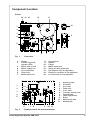
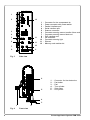
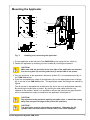
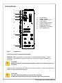
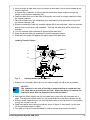
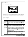
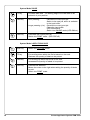
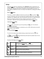
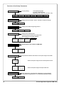
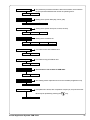
PAM 3000 Printer-Applicator-System Quick Operators Guide Edition 9/01 W.H. Brady Lindestraat 21 Industriepark C3 9240 Zele Belgium Tel.: +32 52 457 811 e-mail: [email protected] In accordance with our policy of continual product improvement, we reserve the right to alter specifications without notice Données technique modifiables sans prévais Technische Änderungen vorbehalten 2 Printer-Applicator-System PAM 3000 Table of Contents EU - Conformity Declaration ...................................................................................... 3 Important Safety Information ..................................................................................... 4 Delivery Contents ...................................................................................................... 4 Component Location ................................................................................................. 5 Mounting the Applicator ............................................................................................. 7 Connections ............................................................................................................... 8 Media Loading ......................................................................................................... 10 Control Panel - System Modes ............................................................................... 12 Setup - Overview ..................................................................................................... 15 Operation ................................................................................................................. 18 Maintenance / Cleaning ........................................................................................... 20 Error Mesages ......................................................................................................... 21 EU - Conformity Declaration We declare herewith that as a result of the manner in which the machine designated below was designed, the type of construction and the machines which, as a result have been brought on to the general market comply with the relevant fundamental regulations of the EU Rules for Safety and Health. In the event of any alteration which has not been approved by us being made to any machine as designated below, this statement shall thereby be made invalid. Description: Printer-Applicator-System Type: Brady PAM 3000 Applied EU Regulations and Norms: - EC Machinery Regulations - Machine Safety 98/37/EU EN 292 Teil 2 :1995-06 - EC Low Voltage Regulations - Data and Office Machine Safety 73/23/EEC EN60950 :1992 + A1 :1993 + A2 :1993 - EC Electromagnetic Compatibility Regulations - Threshold values for the Interference of Data Machines - Limits for harmonic current emission 89/336/EEC EN 55022 :1998 - Limits of voltage fluctuation and flicker - Interference Resistance in both Industrial and Small Plants EN 61000-3-2 :1995+A1 :1998 +A2 :1998+A14 :1999 :2000 EN 61000-3-3 :1995 EN 55024 :1998 Signed for, and on behalf, the Manufacturer : cab Produkttechnik Sömmerda Sömmerda, 10.09.01 Erwin Fascher Managing Director Printer-Applicator-System PAM 3000 3 Important Safety Information CAUTION ! Pay special attention to the following safety guidelines : 1. The PAM 3000 printer is built exclusively to print labels and tags, continuous paper, etc. Do not use other materials than listed in the Operators Manual. 2. Connect the printer only to an outlet with the correct voltage ! The printer is configured for either 230V or 115V power supply, which can be switched using the input voltage selector at the right side of the printer. Connect only to a power outlet with a grounded contact. 3. The printer must only be connected to devices which have extra low voltage. 4. Power must be OFF before plugging in any accessory or connecting the printer to a computer, etc. Also switch power off on all appliances before disconnecting. 5. Do not expose the printer to any moisture, or use in damp or wet areas. 6. In operation moving or rotating parts are easily accessible. Therefore, keep long hair, jewelry, loose clothes away from these parts. 7. During the print process the printhead will become hot. Use extra caution when touching the printhead. 8. Before starting any maintenance, switch the printer OFF and disconnect it from the power supply. 9. Only qualified trained service technicians should attempt to repair your printer if damaged or in need to repair. Delivery Contents Inspect the packaging and contents immediately after receipt for possible damage caused by shipping. The supplied equipment depends on the requested options. Compare the delivered accessories with your order. NOTICE ! Please keep the original packaging in case the printer must be returned. 4 Printer-Applicator-System PAM 3000 Component Location Printer 15 14 13 12 11 10 1 2 3 9 4 5 6 Fig. 1 7 8 Front view 1 - Display 2 - Function keys with indicator LEDs 3 - Ribbon take up hub 4 - Ribbon supply hub 5 - Print mechanism 6 - Guide roller 7 - Media rewind hub 8 9 10 11 12 13 14 15 - Knurled knob Adapter Flange Media supply hub Swing arm with guide roller Pre-dispense key (for applicator) Electronic connector for the applicator Air connectors for the applicator 1 2 3 4 5 6 7 8 9 10 11 1 2 3 4 5 6 Fig. 2 7 8 9 - Adjusting plate Printhead Print roller Feed roller Pinch roller Transport locking lever Peel-off table Label edge sensor Brake Media guide axle Media guide 10 11 Detailed view of the print mechanism Printer-Applicator-System PAM 3000 5 1 2 12 3 4 5 11 6 11 7 10 8 9 Fig. 3 1 2 3 4 5 6 7 8 9 10 11 12 - Connector for the compressed air Power connector with power switch Parallel interface port Serial interface port Scanner connector Connector warning sensor transfer ribbon end Connector warning sensor label end PLC interface port DIP switches Connector warning light Silencer Memory card module slot Side view 6 5 1 2 3 4 5 6 - Connector for the electronics Pad holder Pad Turn cylinder Slide valve Lift cylinder 4 3 1 Fig. 4 6 2 Front view Printer-Applicator-System PAM 3000 Mounting the Applicator 1 2 1 6 7 1 3 8 9 1 4 8 5 Fig. 5 Installing and connecting the applicator 1. Put the applicator at the left side of the PAM 3000 printer using the four holes (1). 2. Fasten the applicator by screwing the four screws (8) including the washers. CAUTION ! Make sure that the two bolts at the rear side of the applicator are inserted into the long hole (2) and the guide hole (3) on the side of the printer. 3. Plug the connector of the applicator's electronic system (7) in the peripheral port (4) of the PAM 3000 printer. 4. Push the compressed air tubes of the applicator (6) into the appropriate push-in-fittings (5) on the top of the PAM 3000 printer. The appropriate tubes and fittings are marked by figures. The lift cylinder is equipped with a slide valve (9), which can only be actuated manually. By delivering the slide valve is closed. By opening the slide valve (slide the ring upwards to the position "bleed") it is possible to remove the pad from its upper position as the compressed air supply is closed and the applicator is switched off. CAUTION ! Pay attention to the pad while opening the slide valve. It should be swung away from the peel-off edge of the printer (90°-position). CAUTION ! The slide valve must be closed during operation. Otherwise the lift cylinder can be moved without control, which can cause damages. Printer-Applicator-System PAM 3000 7 Connections 1 2 3 4 5 6 1 2 3 4 5 6 7 8 9 - Air connector Voltage selector Voltage selector cover Power switch Power supply connector Parallel interface port Serial interface port Inteface port for scanner PLC interface port 7 8 9 Fig. 6 Connections Connection to the Compressed Air Supply PAM 3000 needs for operation the connection to a compressed air supply. The air connector (1) is located at the side of the printer. The push-in-fitting is suitable for a 8mm-tube. CAUTION ! Make sure that the compressed air supply is switched off while connecting the printer. Insert the tube of compressed air supply into the push-in-fitting (1). Insert the tube firmly. Adjust the required operating pressure. CAUTION ! Use only filtered compressed air to operate the printer. Guarantee an operating pressure of constant 5 bar during operation. 8 Printer-Applicator-System PAM 3000 Connection to Power Supply The PAM 3000 is designed for use with 230V A.C/ 50Hz (standard) or 115V A.C/60Hz. CAUTION Before connecting the printer to the power supply, make sure that the voltage selected on the power supply module of the printer is the same as your main power supply ! To change the voltage setting, open the cover (3) and remove the voltage selector from the power unit. CAUTION ! If you have changed the operating voltage of your printer the fuses need replacing as stated below ! 230V - 2 x T 4A 115V - 2 x T 6.3A When delivered, the correct fuses for the pre-selected operative voltage are installed. You will find the necessary fuses for the other voltage in the accessories package. Slide the voltage selector back into the power supply module so that the correct voltage is visible in the lid window. Connect the printer to a grounded outlet using the power cable supplied in the accessories package. Connection to a Computer Select the required interface settings using the Setup procedure and connect the printer to the computer by a suitable interface cable. CAUTION ! Make sure that all connected computers and their connecting cables are correctly grounded. Printer-Applicator-System PAM 3000 9 Media Loading Preparation of the Label Supply Hub PAM 3000 is equipped with a rotating label supply hub, which is able to take up rolls with a core diameter of 76 mm. To take up these label rolls it is necessary to mount two adapters (3) onto the supply hub : Put the first adapter (3) onto the supply hub (2) and slide it to the wind plate (4) until it blocks. Tighten the knurled srew (1). Put the second adapter onto the supply hub (2) and slide it against the wind plate until the distance between the outer edge of the adapter and the wind plate (4) is a little less than the width of the label roll. Tighten the knurled screw (1). 4 3 3 1 Fig. 7 1 2 Preparation of the label supply hub Loading Labels 1 2 3 4 5 6 7 Fig. 8 8 9 10 11 12 13 Label loading 1. Place the label roll (1) onto the prepared media supply hub (4) and slide it down against the wind plate (3). The solid line represents the feed path of outside-rolled labels, the broken line of inside-rolled labels. 2. Put the flange (5) on the supply hub (4), slide it down against the label roll (1) and fix it at the supply hub by tightening the knurled knob (2). 3. Slide the media guide (11) outwards as far as possible. 4. Unlock the transport locking roller (7) by pressing the knurled knob (8) downwards. 10 Printer-Applicator-System PAM 3000 5. Unroll a length of label stock from the media roll and feed it first to the printhead (9) as shown in figure 8. It is particularly important to ensure that the media strip slides properly through the fittings of the photocell assembly (10). 6. Feed the label stock out of the side of the printer until there is enough material to reach the internal rewinder. 7. Take off all labels from the outstanding liner, and feed the liner as shown in figure 8 to the internal rewinder (12). 8. Slide the media strip under the rewinder clamps (6) to the wind plate. Hold the rewinder and turn the knurled knob (13) clockwise. That way the label strip will be fixed at the rewinder. 9. Turn the rewinder (12) clockwise for tightening the label strip. 10. Press the knurled knob (8) upwards to close the transport system. 11. Slide down the guide (11) against the upper edge of the label strip. Loading Transfer Ribbon 1 Fig. 9 4 2 5 3 6 Loading thermal transfer ribbon 1. Slide the roll of transfer ribbon (4) onto the ribbon supply hub (5) as far as possible. NOTICE ! Pay attention to the side of the ribbon material which is coated with ink ! The inked side is generally the dull side. When the ribbon is inserted, the inked side must face the opposite side of the printhead ! 2. Hold tight the ribbon supply hub (5) and rotate the knurled knob (6) clockwise until it stops. That way the transfer ribbon roll (4) will be attached to the ribbon supply hub (5). 3. Slide an empty cardboard core (1) onto the ribbon take up hub (2) and fix it by clockwise turning the knurled knob (3). 4. Feed the transfer ribbon along the path as shown in figure 9, then attach it to the core (1) using adhesive tape or a label. 5. Turn take up hub (2) counterclockwise in order to smooth and stretch the ribbon. Printer-Applicator-System PAM 3000 11 Control Panel The front control panel of the PAM 3000 is fitted with 4 function keys with indicator LEDs, and a 2x16 character digital LCD display. The control panel display constantly provides the operator with the actual information concerning the current printer mode and label processing. The indicator LEDs support the information shown in the display by indicating which keys have to be pressed (e.g. in the event of a fault). Function of the LED's The illuminated LED's show the following printer states : LED ONL - PAM 3000 is ready to print LED FF - Only if an applicator is installed : request to press the key to re-synchronize the paper feed after the appearance of an printer error LED CAN - Error message; print job can be cancelled by pressing the key LED PSE - The printer is paused; print job is temporarily interrupted by pressing the key or sending of a PAUSE-command via interface; print job can be continued by pressing the PAUSE-OFF command again or sending a - Error message; LED is flashing, if there is a fault (e.g. "Out of paper) which is easily correctable by the operator, following which the printing process may be continued by pressing the 12 key Printer-Applicator-System PAM 3000 Function of the Keys The function of the keys is dependent on the System Mode of the printer : System Mode ONLINE ONL key Switch into OFFLINE mode. (LED ONL off) FF key Provides label feed. The leading edge of the next label to be printed is in print position. CAN key Deletes data of the previous print job in internal memory. Following that, "Pause reprint" is not available. (see PSE key) PSE key Repeats the print of the last label, after the previous print job has been completed. (only when setup parameter "Pause reprint" is on) ONL key + CAN key Pressing both keys together for at least 5 seconds will switch into the SETUP mode. (LED ONL off) System Mode OFFLINE ONL key Switch into ONLINE mode. (LED ONL on) FF key Provides label feed. The leading edge of the next label to be printed is in print position. CAN key Switch into LABEL FROM CARD mode. (only if memory card is installed and formats are stored on it) PSE key Display shows current printer mode. ("Printer info") System Mode PRINT CAN key short pressing : Cancels the current print job. Switch to the next job, which is available in the input buffer longer pressing (>1s): Cancels the current print job. Clears the input buffer (LED CAN blinks), Switch into ONLINE mode.(LED ONL on) PSE key Interrupts the current print job. Switch into PAUSE mode. (LED PSE on) Printer-Applicator-System PAM 3000 13 System Mode PAUSE FF key Provides label feed. The leading edge of the next label to be printed is in print position. CAN key short pressing : PSE key Continues the current print job. Switch into PRINT mode. (LED PSE off) Cancels the current print job. Switch to the next job, which is available in the input buffer longer pressing (>1s): Cancels the current print job. Clears the input buffer (LED CAN blinks), Switch into ONLINE mode (LED ONLon). System Mode LABEL FROM CARD 14 ONL key Switch into OFFLINE mode. FF key For scrolling down within the file list stored on the card. Reduces the quantity of labels to be printed. CAN key For scrolling up within the file list of the card. Increases the quantity of labels to be printed. PSE key Confirms file selection. Moves the cursor to the right when setting the quantity of labels to print. Switch into PRINT mode. Printer-Applicator-System PAM 3000 Setup Using the setup mode, the configuration of the PAM 3000 may be customized to suit specific requirements. Initial setup should be performed when operating the printer for the first time. Changes which become necessary to process different print jobs, e.g. when different materials are used, can mostly be accomplished by changing the software settings. Start of Setup Mode This mode is initiated by either simultaneously pressing the key and the key when switching on the printer and keep them pressed down until the system test is completed, or in ONLINE mode, press the same two keys down for at least 5 seconds. Each time a parameter setting has been changed, there will be a request for confirmation. There will not be a general request before leaving the setup mode. Leaving the Setup Mode The setup mode can be left at any point by pressing the key. The confirmed parameters will be saved. If an already confirmed setting is not desired any more, switch off the printer during the setup mode to cancel changes. Restore the Default Setup To return to the original factory default settings, press all three keys, the the key, and the key, key simultaneously and keep them pressed down until the display shows "--- RESTORE ---". Function of the Keys in the Setup Mode ONL key Stores the chosen settings of the setup parameters and completes the SETUP mode. (i.e. switch into ONLINE mode/ LED ONL on) FF key Skips to next setup parameter. Reduces numerical setup values. CAN key Skips to previous setup parameter. Increases numerical setup values. PSE key Confirms selected settings for parameters. Printer-Applicator-System PAM 3000 15 Overview of the Setup Parameters Country Deutschland Belgie Country setting : France Suomi Transfer Print On Bottom-Reflect Top-Reflect* Setting of the interface type at serial interfaces setting of the baud rate and the protocol or network address RS-422 Baud rate Protocol The parameter defines the location of the print image on the label. Offset of the print image across the transport direction. Y : - y.y mm Y : ± y.? mm Y : ± ?.y mm Heat level 16 Centronics - x.x mm ± x.? mm ± ?.x mm X : x.x mm X : x.? mm X : ?.x mm +x RS-485 Baud rate Network address This function is not usable for PAM 3000. Printhead pos. Y : + y.y mm Y : ± y.? mm Y : ± ?.y mm Suisse Danmark Setting of the label recognizing method Peel position + x.x mm ± x.? mm ± ?.x mm Schweiz Ceska republica Off Interface RS-232C Baud rate Protocol USA España Setting of the print mode : Direct Thermal or Thermal Transfer Label sensor Gap sensor United Kingdom Italia LCD display language Formats of date and time Measuring unit ( USA: inch, all other: mm) Offset of the print image in transport direction. Basic adjustment of the darkness (depending on the printhead) "-9" indicates the lightest and "+9" indicates the darkest setting. -x Printer-Applicator-System PAM 3000 Printer info The parameter provides information about the firmware, the cumulative length of printed media and the number of operating hours. Version xxxxx xxx m / xxx h Set date DD.xx.xxxx Setting of the system date (day, month, year) xx.MM.xxxx Set time hh.xx.xxxx xx.xx.YYYY Setting of the system time (hour, minute, second) xx.mm.xx Character set xx.xx.ss Setting of the character set Windows 1252 Windows 1250 ISO 8895-1 Codepage 850 EBCDIC Macintosh Codepage 852 ISO 8895-8 Format Card No Command to format a PCMCIA card Yes Copy Memory Card Yes Command to copy a PCMCIA card No Backfeed head lift-off This function is not usuable for PAM 3000. head down Debug mode Off The "Debug mode" represents a tool for the firmware programmer only On Pause reprint If the paramter is active, after completion of a print job, the print of the last label may be repeated by pressing the On key. Off Printer-Applicator-System PAM 3000 17 Operation Special Settings for the Operation There are four DIP-switches to determine several types of operation. The DIP-switches are located at the right side of the printer. DIP-switch Parameter ON OFF 1 Label format small large 2 Recycle part not installed installed 3 Applicator installed not installed 4 Print repeat no yes DIP-switch 1 - This switch is set on "ON" when small labels are used. By using large labels the switch has to set on "OFF". DIP-switch 2 - If the switch is set on "ON" it is not possible to dispose the bad labels recognized by a scanner at a recycle part. If the switch is set on "OFF" it is possible to apply the bad labels on the recycle part. It is recommended to set the switch always on "ON" if no scanner is used. DIP-switch 3 - If the switch is set on "ON" the printer notices that there is an applicator to carry out the further steps after printing. If the switch is set on "OFF" it is necessary to guarantee the correct further processing of the applying process by other features for example manually or by industrial robots. DIP-switch 4 - If the switch is set on "ON" a bad label recognized by a scanner will not printed again. If the switch is set on "OFF" the print of a bad label recognized by a scanner will be repeated. It is recommended to set the switch always on "ON" if no scanner is used. Positioning of the Labels The labels could be applied parallel to the print line (0°-position) as well as across to the print line (90°-position). An external signal via PLC interface triggers the type of labelling (see appendix C of the Operators Manual). The take-over of the labels is carried out in the 0°-position for both types of applying. The procedure of the following movements is different. 18 Printer-Applicator-System PAM 3000 Standard Operation NOTICE ! Check all external connections before starting to print. Make sure that the media is loaded corresponding to the instructions. Check that the transfer ribbon is loaded properly before starting to print. CAUTION ! Make sure that the slide valve of the lift cylinder is closed during operation. Otherwise the lift cylinder can be moved without control. This fact can cause damages. NOTICE ! Make sure that the pad is not covered by a label when switching on the device. Switch on the compressed air supply. Switch on the power supply of the Printer-Applicator-System. The printer carries out a short system test and following the display shows the system mode "ONLINE". If a hardware failure occurs during the system test the type of the failure will be shown. In this case the printer should be switched off and on again. If the failure occurs again call for service. NOTICE ! Before starting the first print job after switching on the printer it is necessary to synchronize the label feed : Press the key to generate a synchronous running. Remove the processed labels manually. Start the print job. Start the labelling process via PLC interface. With every start signal received by the PLC interface the printer performs one application cycle. Printhead is moved down. Label is printed. Printhead is moved up. Pad is moved to the peel-off table, vacuum is switched on. Label is peeled off by moving back the peel-off table and taken by the pad of the applicator module. Pad is driven to move back into the upper end position. Peel-off table is driven to move back into the front position. Label is transported into the labelling position, vacuum is switched off. Label is placed onto the product. Pad is driven to return in its upper end position. Now the printer-applicator-system is ready for the next cycle. Printer-Applicator-System PAM 3000 19 Maintenance / Cleaning General The printer PAM 3000 only requires a minimum of maintenance. It is most important to clean the printhead on a regular basis. This will guarantee a permanent high quality of the print image. Moreover, it helps to prevent an early wear of the printhead. Apart from that, the servicing only requires you to clean the outside of the printer occassionally. Cleaning the Printhead While operating, dirt such as paper dust or particles of ink or back coating from the ribbon may accumulate on the thermal printhead. This can cause a deterioriation of the print quality (e.g. different contrasts on the label, appearance of light horizontal lines, etc.). In that case, the printhead needs cleaning. WARNING ! Disconnect power supply ! Switch off compressed air ! Recommended cleaning intervalls : Direct Thermal Printing : at every 1200 m Thermal Transfer Printing : each time you change the ribbon CAUTION ! Do not use any sharp objects for cleaning the printhead ! Do not touch the protective glass layer of the printhead ! Clean the printhead as follows : Remove label material and transfer ribbon from the printer. Clean the printhead surface with a special cleaning pen, or use a cotton swab soaked with isopropyl alcohol. Allow it to dry for about 2 to 3 minutes before restarting the printer. 1 Fig. 10 20 Cleaning the printhead Printer-Applicator-System PAM 3000 Error Messages/ Problem Solution The PAM 3000 is equipped with a comprehensive self diagnostic system which will indicate errors in the display of the printer. Also, the operator will be informed by the LEDs whether the fault is correctable and will, therefore, allow to continue the current print job after corrections (e.g. "Out of paper"), or the fault may require you to cancel the current print job. Correctable Errors While processing a print job, an error has occured which may be corrected by the operator, and also allows you to continue the print job after fault correction. The top line of the display shows alternately the type of fault and the total of the remaining labels of the current print job. The LED CAN is switched on, the LED PSE is flashing. Function Keys CAN key PSE key short pressing : Cancels the current print job. Switch to the next job, which is available in the input buffer longer pressing (>1s): Cancels the current print job. Clears the input buffer (LED CAN blinks), Switch into ONLINE mode.(LED ONL on) Continues current print job after error correction. Switch into PRINT mode. (LED ONL on, LED CAN off, LED PSE off) Irrecoverable Errors While switching on the printer or during printing, a fault has occured which cannot be cleared by the operator without cancelling the current print run (e.g. hardware fault). The display shows the type of fault. The LED CAN is flashing. Function Keys CAN key Cancels the current print job. Switch into ONLINE mode. (LED ONL on, LED CAN off, LED PSE off) If ONLINE mode cannot be entered, switch printer off and on again. If the fault remains again, contact Technical Service Printer-Applicator-System PAM 3000 21 This page is intentionally left blank. 22 Printer-Applicator-System PAM 3000