1
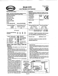
ECO-SHREDDER BY DUROSTAR
OWNERS OPERATING MANUAL
CHIPPER / SHREDDER / MULCHER MODEL ES1600
SPECIFICATIONS:
Horse Power: 2.5HP
HopperSize: 15-1/4" x 10-3/8"
Side Chute: 1-3/8" x 2-5/16"
R.P.M:
3450
THANK YOU FOR PURCHASING AN ECO-SHREDDER, CHIPPER / SHREDDER / MULCHER.
Your new Chipper/Shredder/Mulcher has been engineered and manufactured to the highest standards of
dependability, ease of use and operator safety. Properly cared for, it will give you years of rugged, trouble-free
performance.
CAUTION: Carefully read through this entire owner's manual before using your
new Chipper / Shredder / Mulcher.
Pay close attention to the Rules for Safe Operation, Warnings and Cautions.
If you use you Chipper / Mulcher / Shredder properly and only for what it is intended, you will enjoy years of safe,
reliable service.
Thank you again for buying DUROSTAR equipment.
SAVE THIS MANUAL FOR FUTURE REFERENCE
RULES FOR SAFE OPERATION
10)
The purpose of safety rules is to attract your attention to
possible dangers. The safety symbols and the explanations
with them require your careful attention and understanding.
The safety warnings do not by themselves eliminate any
danger. The instructions or warn ings they give are not
substitutes for proper accident prevention measures.
11)
12)
SAFETY ALERT SYMBOL. Indicates caution or
warning. Maybe used in conjunction with other
symbols or pbtures.
13)
14)
WARNING: Failure to obey a safety warning can
result in serious injury to you or to others. Always
follow the safety precautions to reduce the risk of
fire, electric shock and personal injury.
15)
WARNING: Do not attempt to operate this tool until
you have read thoroughly and understood
completely, safety rules, etc. contained in this
manual. Failure to comply can result in accidents
involving fire, electric shock or serious personal
injury. Save owners manual and review frequently
for continuing safe operation and instructing others
who may use this tool.
16)
17)
18)
The operation of any tool can result in foreign objects being
thrown into your eyes, which can result in severe eye
damage. Before beginning power equipment operation,
ahways wear safety goggles or safety glasses with side
shields and a full face shield when needed. Wear a wide
vision safety mask for use over eyeglasses or standard
safety glasses with side shields.
1.
2.
3.
4.
5.
6.
7.
8.
9.
19)
KNOW YOUR POWER TOOL. Read owners
manual carefully. Leam rts applications and
limitations as well as the specific po!ential hazards
related to this tool.
GUARD AGAINST ELECTRICAL SHOCK BY
PREVENTING BODY CONTACT WITH
GROUNDED SURFACES. For example, pipes,
radiators, ranges, refrigerator enclosures.
KEEP WORK AREA CLEAN. Cluttered areas invite
accidents.
AVOID DANGEROUS ENVIROMENT. Don't use
power tools in damp or wet locations or expose to
rain. Keep work area well lit.
KEEP CHILDREN AND VISITORS AWAY. Visitors
should wear safety glasses and be kept a safe
distance from work area. Do not let visitors contact
tool or extension cord.
STORE IDLE TOOLS. When not in use, tools
should be stored in a dry and high or locked place
out of reach of children.
DON'T FORCE TOOL. It will do the job better and
safer at the rate at which it was deskjned.
USE RIGHT TOOL. Don't force small tool or
attachment to do the job of a heavy duty tool. Don't
use a tool for a purpose not intended.
DRESS PROPERLY. Do not wear loose cbthing or
jewelry. They can be caught in movhg parts.
Rubber gloves and non-skid footwear are
recommended when working outdoors. Also wear
protective hair covering to contain long hair.
20)
21)
ALWAYS WEAR SAFETY GLASSES. Everyday
eyeglasses have only impact resistant lenses, they
are not safety glasses.
PROTECT YOUR LUNGS. Wear a dust mask if
operation is dusty.
PROTECT YOUR HEARING. Wear hearing
protection during operation.
DON'T OVEREACH. Keep proper footing and
balance at all times. Do not use tool on an unstable
support.
MAINTAIN TOOLS WITH CARE. Keep tools sharp
and clean for better and safer performance. Follow
instructions for lubricating and changing accessories.
REMOVE ADJUSTING KEYS AND WRENCHES.
Form a habit of checking to see that keys and
adjusting wrenches are removed from tool before
turning it on.
NEVER USE IN AN EXPLOSIVE ATMOSPHERE.
Normal sparking of the motor could ignite fumes.
KEEP HANDLES DRY, CLEAN AND FREE OF
OIL AND GREASE. Always use a clean cloth when
cleaning. Never use break fluids, gasoline,
petroleum based products or any strong solvents to
clean you tool.
STAY ALERT AND EXERCISE CONTROL. Watch
what you are doing and use common sense. Do not
rush.
CHECK DAMAGED PARTS. Before further use of
the tool a guard or any other part that is damaged
should be carefully checked to determine that it will
operate properly and perform its intended function.
Check for alignment of moving parts, binding of
moving parts, breakage of parts, mounting and any
other conditions that may affect its operation. A
guard or any other part that is damaged should be
properly repaired or replaced by and authorized
service center.
DO NOT USE TOOL IF SWITCH DOES NOT
TURN IT ON AND OFF. Have defective switches
replaced by authorized service center.
DO NOT OPERATE THIS TOOL WHILE UNDER
THE INFLUENCE OF DRUGS, ALCOHOL OR
ANY MEDICATIONS.
SAVE THESE INSTRUCTIONS
FOR FUTURE REFERENCE
Due to continued product
refinement policy, product features
and specifications can and will
change without notice.
Check current features and
specifications with your retailer.
-1 -
• HANDLE
Insert the handle bar into the handle shafts located at the
rear of the machine. Align the holes in the handle bar to the
holes in the handle shafts and secure with the 2 knobs as
shown in Fig. 4 & 5.
• ASSEMBLE FRAME & WHEELS
Align the holes in the wheels to the holes in the axle section
of the frame and secure tightly with the bolts, spring washers
and nuts provided as shown in Fig. 1.
Affix the hub caps to the wheels.
Fig. 2
. SAFTEY SWITCH
The safety switch that is located on the cutter base is
activated when the Top Hopper assembly is removed to help
prevent accidental starting. Fig. 6
. TOP HOPPER
Place the Top Hopper onto the metal feed tube and align the
attaching holes. Secure the one way screw.
. OPERATION
Read and understand the safety instructions in this
owner's manual before using your ECO-SHREDDER.
Connect the machine to a suitable power outlet. To start the
machine, place the On/Off switch located at the rear of the
motor to "ON" position. Fig. 7. To stop the machine, switch
to the "OFF" position.
-2-
• ATTACHING MULCH BAG
Place a heavy duty garbage bag over the lip of the discharge
chute and secure into position using a strap.
Fig. 8
> DISASSEMBLY
I. Unscrew the 3 Top Hopper assembly knobs and remove
the Top Hopper assembly.
!. Rotate the cutter base counter clockwise and place a
piece of wood between the cutter base and the cutting
chamber wall so as to stop the cutting base from rotating.
Fig. 9
i. Remove the center hold down bolt by turning it counter
clockwise using a wrench.
t. Remove the square washer, square bushing, V-cutter
and V-cutter base to expose the cutter base.
• MAINTENANCE
Your ECO-SHREDDER has been designed for a low level of
maintenance, involving routine cleaning and inspection. The
motor of the machine is maintenance free and requires no
attention. For best results the blades must be kept sharp at
all times. The blades have dramatically less cutting power
when dull. The machine will tear rather than cut when the
blades are dull. When this occurs rotate the double sided
blades or replace the blades immediately.
• SHREDDING BLADES MAINTENANCE
To inspector replace the double sided shredding blades
there is no need to remove the V-cutter or cutting base. To
remove simply undo the countersunk screws with the hex
wrench provided wrth the machine and turn them 180°.
These blades are double ground and can be used on both
skies. When dull on both sides replace with new blades and
make sure they are screwed in tightly.
WARNING
Before attempting any maintenance, switch the
machine off and disconnect the power cord from
power source.
• JAMMING
If blades become jammed, switch off the machine and
disconnect the power cord from the power source. Always
wear gloves when attempting maintenance of the cutting
chamber. Unscrew the 3 securing Top Hopper assembly
knobs. Remove the Top Hopper assembly and remove the
obstruction from the cutting chamber.
• ASSEMBLY
This is carried out in the reverse order to that of the
disassembly but with careful inspection of all components.
Ensure that the cutter base is assembled with the scraping
plates facing down towards the motor and that the spring
washer is situated under the head of the center hold down
bolt. Fig. 10
Before replacing the top cover assembly, ensure that the
V-cutter is positioned as shown in Fig. 11.
Replace the Top Hopper assembly and secure with the three
(3) Top Hopper assembly knobs.
WARNING
Take extreme care not to come in contact with
cutting blades. Assemble the Top Hopper in reverse
order stated above.
Fig. 10
WARNING
If ejection chute becomes clogged or cutting blades
become jammed, under no circumstances should
you place your hands in the ejection chute to try to
clear the obstructbn as this will lead to serious
injury.
. V-CUTTER MAINTENANCE
• Switch the machine off and disconnect the power cord
ensuring all moving parts are comptetely stopped.
• Wear gloves when attempting any maintenance to the
cutting blades.
• If blades require replacing, ensure you use DUROSTAR
genuine parts.
• CLEANING
After use, always wipe clean the outside of the machine
to remove any build up of material with a damp cloth.
Clean the inside of the cutting chamber and remove any
left over material.
-3-
• TOP HOPPER - FRONT CHUTE
• OVERLOAD PROTECTION AND MOTOR JAMMING
If overfeeding clogs the machine the overload protection
switch may cut out the motor. To restart, first switch the
machine off and disconnect the power cord. Unscrew the 3
Top Hopper assembly knobs and remove the Top Hopper
assembly to remove any clogged debris from the cutting
chamber. If the top cover assembly becomes jammed and
will not lift off, turn the V-cutter by pushing a piece of wood
through the back chute of the Top Hopper to rotate the
V-Cutter to enable the top cover assembly to be removed.
Reset the motor overbad protection switch. Fig. 14.
The sloping chute of the Top Hopper is designed to accept
leaves and small garden clippings. Shredding and mulching
is achieved by natural suction of the debris through the blade
chamber. Do not overload and do not feed wet, soggy
material into the machine as this may clog the blade chamber
and the discharge chute. Fig. 12
If a finer mulch is required than is initially achieved, re-feed
the mulch through again until the desired result is obtained.
DO NOT FEED SOLID BRANCHES THOUGH THE
TOP HOPPER CHUTE.
• SIDE CHUTE
The chute located at the rear of the machine is specially
designed to accept solid garden clippings and branches up to
1-1/4" in diameter.
IMPORTANT:
When feeding long, large diameter material, controlthe rate
of feed by pulling back on the material so as not to stall or
overload the motor. Fig. 13
IMPORTANT:
Before replacing top cover assembly ensure that the V-cutter
is positioned as shown in Fig. 15.
Replace the top cover assembly together with the three (3)
Top Hopper assembly knobs ensuring they are tight.
WARNING
Do not under any circumstances place hands inside the
feeding chutes while the machine is in operation. Force
feeding of debris is not necessary due to the natural suction
of the machine.
• Motor jamming
When the motor stopped by over thick branch or other
cause, the over current protective device will be off, then
turn off the switch, use the "L" hexagon spanner to turn the
motor shaft though the hole on the bottom of the motor
house. After resolve block, please turn on the over current
protective device and ON/OFF switch, if still block, please
take apart the house to resolve again.
. CONTACT INFORMATION:
Durostar
Ph: 800-629-3325
1669 Puddingstone Dr.
Fax: 800-629-2329
La Verne, CA. 91750
Email : [email protected]
-4-
DUROSTAR POWER EQUIPMENT
WARRANTY
Subject to the warranty conditions below, this
DUROSTAR product, (hereafter called "the
Product"), is warranted by DUROSTAR to be
free from defects in material and workmanship
for a period of 12 months from the date of
original purchase covering both parts and labor.
Under the terms of this warranty, the repair or
replacement of any part shall be at the option of
DUROSTAR or its authorized agent. Should
service become necessary during the warranty
period, the owner should contact DUROSTAR
directly. In order to obtain warranty service the
owner must provide the sales invoice and
Warranty Certificate to confirm date of purchase.
This product is sold by the retailer or agent as
principal and the retailer has no authority from
the company to give any additional warranty or
guarantee on the DUROSTAR'S behalf except
as herein contained or herein referred to.
Warranty Conditions:
This warranty only applies provided that the
Product has been used in accordance with the
manufacturer's recommendations under normal
use and reasonable care (in the opinion of
DUROSTAR) and such warranty does not cover
consumable components, damage, malfunction
or failure resulting from misuse, neglect, abuse
or used for a purpose for which it was not
designed or is not suited and no repairs,
alterations or modifications have been attempted
by other than an Authorized Service Agent. This
warranty will not apply if the tool is damaged by
accident or if repairs arise from normal wear and
tear.
Accessories such as blades are excluded from
this warranty. Normal consumable parts such as
carbon brushes, bearings, blades and cutters
are excluded from this warranty.
DUROSTAR accepts no additional liability
pursuant to this warranty for the costs of
traveling or transportation of the Product to and
from the service dealer or agent.
Nothing herein shall have the effect of excluding,
restricting or modifying any condition, warranty,
right or liability imposed, to the extent only that
such exclusion, restriction or modification would
render any term herein void.
Ph: 800-629-3325
Fax: 800-629-2219
Email: [email protected]
DUROSTAR
1669 Puddingstone Dr.
La Verne, CA. 91750
THIS WARRANTY FORM
SHOULD BE RETAINED BY THE CUSTOMER AT ALL TIMES.
For your record and to assist in establishing date of purchase (necessary for in-warranty service), please
keep you purchase invoice and this form, completed with the following particulars.
PURCHASED FROM:
ADDRESS OF RETAILER:
DATE:
MODEL NO:
SERIAL NO:
Present this form with your Purchase Invoice when Warranty Service is requested.