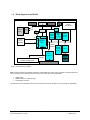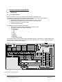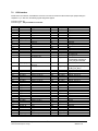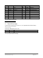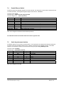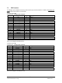
1
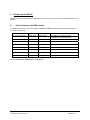
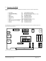
EB 200 . Evaluation Board ERTEC 200 Manual Copyright © Siemens AG 2010. All rights reserved. Technical data subject to change Page 1 EB200 Manual Version 1.1.4 Edition (10/2010) Disclaimer of Liability We have checked the contents of this manual for agreement with the hardware and software described. Since deviations cannot be precluded entirely, we cannot guarantee full agreement. However, the data in this manual are reviewed regularly. Necessary corrections are included in subsequent editions. Suggestions for improvement are welcomed. Copyright © Siemens AG 2010. All rights reserved The reproduction, transmission or use of this document or its contents is not permitted without express written authority. Offenders will be liable for damages. All rights, including rights created by patent grant or registration of a utility model or design, are reserved. All product and system names are registered trademarks of their respective owner and must be treated as such. Technical data subject to change. Copyright © Siemens AG 2010. All rights reserved. Technical data subject to change Page 2 EB200 Manual Version 1.1.4 Preface Contents of this Manual Detailed description of the individual function groups of the EB 200 Connector pin assignment and jumper assignment Target Audience of this Manual This manual is intended for hardware developers who want to use the ERTEC 200 for new products. Experience working with processors and designing embedded systems and knowledge of Ethernet are required for this. The manual serves as a reference for software developers. Sections 7 and 8 describe the jumper settings and connectors that are required for software tests (e.g., debugging, terminal outputs, etc.). Structure of this Manual This manual describes the ERTEC 200 evaluation board. The manual is structured as follows: o Section 1 Introduction o Section 2 Hardware Structure of the EB 200 o Section 3 Memory Distribution of the EB 200. o Section 4 Operating Modes of the EB 200 o Section 5 JTAG Interface of the EB 200 o Section 6 Settings of the EB 200 o Section 7 Connectors of the EB 200 o Section 8 Jumpers of the EB 200 o Section 9 Mechanical Structure of the EB 200 o Section 10 List of Terms and References When working with modules, always take precautionary measures against electrostatic charge (ESD – Electrostatic Sensitive Devices). For module handling and installation, refer to /3/. This manual will be updated as required. You can find the current version of the manual on the Internet at http://www.siemens.com/comdec. Copyright © Siemens AG 2010. All rights reserved. Technical data subject to change Page 3 EB200 Manual Version 1.1.4 Guide To help you quickly find the information you need, this manual contains the following aids: o A complete table of contents as well as a list of all figures and tables in the manual are provided at the beginning of the manual. o A glossary containing definitions of important terms used in the manual is located following the appendices. o References to other documents are indicated by the document reference number enclosed in slashes (/No./). The complete title of the document can be obtained from the list of references at the end of the manual. Additional Support If you have questions regarding use of the described block that are not addressed in the documentation, please contact your Siemens representative. Please send your written questions, comments, and suggestions regarding the manual to the hotline via the e-mail address indicated above. In addition, you can receive general information, current product information, FAQs, and downloads pertaining to your application on the Internet at: http://www.siemens.com/comdec Technical Contacts for Germany / Worldwide Siemens AG Automation & Drives ComDeC Phone: Phone: Fax: E-mail: 0911/750-2736 0911/750-2080 0911/750-2100 [email protected] Street address: Mailing address: Würzburgerstr.121 P.O. Box 2355 90766 Fürth Federal Republic of Germany 90713 Fürth Federal Republic of Germany Technical Contacts for USA PROFI Interface Center: One Internet Plaza PO Box 4991 Fax: (423)- 262- 2103 Phone: (423)- 262- 2576 E-mail: [email protected] Johnson City, TN 37602-4991 Copyright © Siemens AG 2010. All rights reserved. Technical data subject to change 4 EB 200 Manual Version 1.1.4 Contents 1 Introduction.............................................................................................................................8 1.1 1.2 1.3 1.4 2 Procedure when Using ERTEC 200 to Develop Your Own PROFINET IO Device ................................ 8 Structure of the EB 200 .......................................................................................................................... 9 Features of the EB 200........................................................................................................................... 9 Block Diagram of the EB 200 ................................................................................................................. 10 Hardware Structure of the EB 200 ........................................................................................11 2.1 ERTEC 200 ............................................................................................................................................ 11 2.1.1 Function Overview ............................................................................................................................ 11 2.1.2 Operating Modes of the EB 200........................................................................................................ 12 2.1.3 Boot Modes of the EB 200 ................................................................................................................ 13 2.1.4 ERTEC 200 Processor and I/O......................................................................................................... 14 2.1.5 PCI Interface..................................................................................................................................... 14 2.1.6 IRT switch ......................................................................................................................................... 14 2.1.7 Interrupt System of the EB 200......................................................................................................... 14 2.1.8 External Memory Interface (EMIF).................................................................................................... 15 2.1.9 Debug and Trace Interface ............................................................................................................... 16 2.1.10 Serial Asynchronous Interfaces ........................................................................................................ 16 2.1.11 General Purpose Interface (GPIO) ................................................................................................... 16 2.2 Memory on EB 200................................................................................................................................. 19 2.2.1 SDRAM Interface.............................................................................................................................. 19 2.2.2 SRAM Interface ................................................................................................................................ 19 2.2.3 Flash Interface .................................................................................................................................. 19 2.2.4 Serial Flash/EEPROM ...................................................................................................................... 19 2.3 CPLD Interface....................................................................................................................................... 20 2.4 Reset System of the EB 200 .................................................................................................................. 20 2.4.1 Reset Button ..................................................................................................................................... 21 2.4.2 PCI Reset ......................................................................................................................................... 21 2.4.3 Watchdog and Software Reset ......................................................................................................... 21 2.5 Clock System of the EB 200................................................................................................................... 21 2.5.1 Clock-Pulse Supply of PCI Interface................................................................................................. 21 2.5.2 Clock Pulse Supply of EB 200 via a Quartz Crystal.......................................................................... 21 2.5.3 Clock Pulse Supply of EB 200 via an Oscillator................................................................................ 21 2.5.4 Cycle for F-Timer .............................................................................................................................. 21 2.6 Ethernet Interface of the EB 200 ............................................................................................................ 22 3 Memory Allocation of EB 200................................................................................................23 3.1 Memory Mapping.................................................................................................................................... 23 3.2 Detailed Memory Description ................................................................................................................. 24 4 Operating Modes of the EB 200 ............................................................................................26 4.1 Operating the EB 200 without programmed Flash.................................................................................. 26 4.2 Operating the EB 200 with programmed Flash....................................................................................... 26 4.3 Operating the EB 200 with LBU Mode.................................................................................................... 26 5 6 JTAG Interface ........................................................................................................................27 Settings on the EB 200 ..........................................................................................................28 6.1 Default Settings of the EMIF Interface.................................................................................................... 28 7 Connectors of the EB 200......................................................................................................29 7.1 7.2 7.3 7.4 7.5 7.6 7.7 7.8 7.9 PCI Interface .......................................................................................................................................... 30 LBU Interface ......................................................................................................................................... 32 External DC Power Supply ..................................................................................................................... 33 Double Ethernet Switch .......................................................................................................................... 34 Serial Asynchronous Interface................................................................................................................ 34 GPIO Interface ....................................................................................................................................... 35 I/O Adapter ............................................................................................................................................. 36 Trace Interface ....................................................................................................................................... 38 JTAG Interface ....................................................................................................................................... 39 Copyright © Siemens AG 2010. All rights reserved. Technical data subject to change 5 EB 200 Manual Version 1.1.4 7.10 JTAG Programming Interface for FPGA (Byte Blaster) .......................................................................... 39 7.11 CPLD Programming Interface ................................................................................................................ 40 8 Settings on the EB 200 ..........................................................................................................40 8.1 Boot/Configuration Connector X10......................................................................................................... 40 8.2 System/Configuration Connector X11 .................................................................................................... 41 9 Structure of the EB 200..........................................................................................................42 9.1 Mechanical Structure.............................................................................................................................. 42 9.2 Front and Display Element ..................................................................................................................... 42 10 Miscellaneous .........................................................................................................................44 10.1 Acronyms/Glossary: ............................................................................................................................... 44 10.2 References: ............................................................................................................................................ 45 Copyright © Siemens AG 2010. All rights reserved. Technical data subject to change 6 EB 200 Manual Version 1.1.4 List of Figures Figure 1: Block Diagram of the EB 200......................................................................................................................... 10 Figure 2: ERTEC 200 Block Diagram ........................................................................................................................... 11 Figure 3: Reset Logic of the EB 200 ............................................................................................................................. 20 Figure 4: Overview of Clock System of the EB 200 ...................................................................................................... 21 Figure 5: Connector Positions on the EB 200 ............................................................................................................... 29 Figure 6: Front Element of the EB 200 ......................................................................................................................... 42 List of Tables Table 1: Selection of Operating Modes and System Functions for EB 200 .................................................................. 13 Table 2: Boot Mode Selection for EB 200..................................................................................................................... 13 Table 3: IRQ Interrupts ................................................................................................................................................. 14 Table 4: FIQ Interrupts.................................................................................................................................................. 15 Table 5: CS Areas of the EB 200.................................................................................................................................. 15 Table 6: GPIO [31:0] on EB 200 ................................................................................................................................... 17 Table 7: GPIO [44:32] on EB 200 as Alternative Function............................................................................................ 18 Table 8: Overview of AHB Master-Slave Access .......................................................................................................... 23 Table 9: Function Groups with Memory Segments Used.............................................................................................. 23 Table 10: Detailed Memory Segment Distribution in the EB 200 .................................................................................. 25 Table 11: Default Settings of EMIF Registers on the EB 200 ....................................................................................... 28 Table 12: Pin Assignment for PCI Interface.................................................................................................................. 31 Table 13: Pin Assignment for LBU Interface................................................................................................................. 33 Table 14: Pin Assignment for External DC Supply ....................................................................................................... 33 Table 15: Pin Assignment for Ethernet Switch Interface (Downlink) ............................................................................. 34 Table 16: Pin Assignment for UART ............................................................................................................................. 34 Table 17: Pin Assignment for GPIO [15 to 0]................................................................................................................ 35 Table 18: Pin Assignment for GPIO [31 to .16]............................................................................................................. 35 Table 19: Pin Assignment for GPIO [44 to 32].............................................................................................................. 36 Table 20: Pin Assignment for X30 EMIF Address Bits.................................................................................................. 36 Table 21: Pin Assignment for X31 EMIF Data Bits ....................................................................................................... 37 Table 22: Pin Assignment for Connectors of I/O Adapter ............................................................................................. 37 Table 23: Pin Assignment for Trace Interface............................................................................................................... 38 Table 24: Pin Assignment of JTAG Interface................................................................................................................ 39 Table 25: Pin Assignment for Byte Blaster FPGA Programming Interface ................................................................... 39 Table 26: Pin Assignment for CPLD Programming Interface........................................................................................ 40 Table 27: Connector X10 for Boot Settings and Some Configuration Settings ............................................................. 41 Table 28: Connector X11 for Configuration and System Settings................................................................................. 41 Table 29: Function of LEDs on Front Panel of the EB 200 ........................................................................................... 43 Copyright © Siemens AG 2010. All rights reserved. Technical data subject to change 7 EB 200 Manual Version 1.1.4 1 Introduction This manual describes the procedure for using the ERTEC 200 for HW development of a PROFINET IO device and the properties of the EB 200 evaluation board. The intended use of the EB 200 evaluation board is as follows: It serves as a template for development of your own PROFINET IO device hardware. It supports development and testing of your own PROFINET IO device application software. It enables testing of your hardware on a supplementary board together with the EB 200, where applicable. 1.1 Procedure when Using ERTEC 200 to Develop Your Own PROFINET IO Device The "DK-ERTEC200 PN IO" CD contains two circuit diagrams: 1. Circuit diagram of the EB 200 EB200 circuit diagrams.pdf 2. Minimum configuration for a PROFINET IO device EB200 AN001 minimal circuit configuration.pdf If you are using the recommended minimum configuration for a PROFINET IO device, no changes (or only minor changes) have to be made in the board support package (BSP) for your additionally required hardware. The board support package adapts the operating system to the hardware, see /3/. Procedure You can use ERTEC 200 to develop your own hardware in one of two ways: o By using a test board on the EB 200 to adapt and test your application circuit o By using ERTEC 200 directly to develop and test your complete target hardware Note the following boundary conditions for hardware development: Minimum Memory Capacity Memory Type Minimum Recommended Flash AMD29DL323GB-90EI/T AMD SDRAM HYP39S25616DT-7.5 Infineon 4 Mbytes 32 Mbytes 4 Mbytes 64 Mbytes Debug Interfaces for Commissioning and Testing Always make provision for connectors on your hardware to the JTAG interface and, if possible, to a serial interface (UART1) of the ERTEC 200 in order to facilitate commissioning. Copyright © Siemens AG 2010. All rights reserved. Technical data subject to change 8 EB 200 Manual Version 1.1.4 1.2 Structure of the EB 200 The EB 200 is implemented in the form of a PCI card. The PCI interface is used only for module tests. In standard configuration the EB 200 is operated as a stand-alone module. The EB 200 is supplied by means of an external plugin power supply (part of the development kit). For debugging the Amontec JTAG debugger including usb cable (both also part of the development kit) can be plugged onto the EB200 as shown in the following picture. 1.3 Features of the EB 200 In addition to the ERTEC 200 with its integrated function groups, the following elements are available on the EB 200: PC front panel element with o 2 RJ45 sockets with integrated magnetics o 2 LEDs Link and Activity per RJ45 socket Optional LED display Speed and Duplex o 2 LEDs for additional status indicators o External DC power supply in stand-alone mode Flash memory 4 Mbytes Flash memory 512 Kbytes, socketed PLCC32 SDRAM 64 Mbytes SRAM 8 Mbytes SPI Data Flash and EPROM Debug and trace interface for ARM946ES-µP RS232 interface for booting, debugging, and monitoring Configuration and boot modes can be set via jumpers Various operating modes of the EB 200 can be set via jumpers Various connectors for external wiring Copyright © Siemens AG 2010. All rights reserved. Technical data subject to change 9 EB 200 Manual Version 1.1.4 1.4 Block Diagram of the EB 200 SYNC External Supply Supply 3,3V 1,5V Debugger I/O Slot for Expansion SPI 25 MHz TX 2xRJ45 with int. Magnetics RS 232 SPI F X RX / T X Trace Boot FLASH 512kB (socked) GPIO ERTEC 200 LBU PCI Target Data Path E M I F PCI Master Datenpfad FPGA PCI Bridge LBU Connector for direct LBU Master Interface /MII Diagnostics FLASH 4MB (16 Bit) SDRAM 2x32MB (32Bit) SRAM 2x4MB (32Bit) CPLD Jumper Jumper Config Jumper Boot PCI-Connector Figure 1: Block Diagram of the EB 200 Note: On the evaluation board EB200 (hardware release ES35 and newer), that is included in the development kit V3.2.0 and newer, the following components are no more used and no more assembled: NAND-Flash SMSC-LAN91C111 Ethernet Chip RJ45-female connector. The boards are fully compatible to the prior version ES34, there are no limitations on functionality for PROFINET. Copyright © Siemens AG 2010. All rights reserved. Technical data subject to change 10 EB 200 Manual Version 1.1.4 2 Hardware Structure of the EB 200 2.1 ERTEC 200 2.1.1 Function Overview Refer to documents /1/ and /2/ for a detailed function description of the ERTEC 200. In this manual, only the main components are described briefly and represented in a block diagram. The following four AHB masters are integrated in the ERTEC 200: ARM946E-S with trace/debug port and high-performance interrupt controllers IRT switch with 64 Kbytes of K-RAM for real-time Ethernet communication External host processor on the LBU interface Single channel DMA controller The following I/O blocks are available to the masters: External memory interface (EMIF) with SDRAM and SRAM controller Two Ethernet interfaces with integrated MII PHYs I/O via APB bridge 45-bit GPIO UART SPI 3 timers F-timer Watchdog Boot ROM System function register The multi-layer AHB bus system enables a largely independent operation of the masters. An internal arbitration logic prevents access conflicts if multiple masters want to access the same I/O block. The function groups of the ERTEC 200 are shown in the following block diagram: TRACE_ C LK 7 AR M 946ES 74 48 Local B u s U n it 1 6 B it (L B U ) M e m o ry C o n tro lle r (E M IF ) M a s te r S la v e M a s te r w ith I- C a c h e (8 k B y te ) , D -C a c h e (4 k B y te ) , D -T C M (4 k B y te ) ARMIn te r r u p tC o n tr o lle r DMAC o n tr o lle r S la v e BSTAP F_C LK 1 1 25M Hz 1 1 C lo c k - U n it 1 ARM9 MUX REF_ C LK ETM PLL 1 R eset 4 Test 100MHz JTA G / D ebug clock E x te r n a l M e m o ry In te rfa c e 48 50MHz L B U / M II + S M I / E T M / G P IO APB In te rfa c e 5 0 M H z / 3 2 B it M a s te r S la v e 14 13 M U X /A rb . M a s te r S la v e AHBW ra p p e r AHBW ra p p e r S la v e M a s te r Slave In p u t s ta g e G P IO Slave 5 0 M H z /3 2 B it 16 13 A H B /A P B B rid g e 1 x UART Slave M u lti- L a y e r - A H B 16 In p u t s ta g e D ecode S P I1 In te rfa c e 8 Slave D ecode Master In p u t s ta g e Slave M U X /A rb . MUX/Arb. In p u t s ta g e 3 x T im e r , W a tc h d o g , F - T im e r 2 32 P 5 P 3 3 2 B it M C -B u s ( 5 0 M H z ) 3 2 B it S C - B u s (5 0 M H z ) E th e rn e tKanal E th e rn e tKanal (P o rt 0 ) (P o rt 1 ) 2 - P o r t S w itc h Slave SMI M II -1 M I I- 0 32 G P IO , UART, S P I, T im e r , W a tc h d o g , r 6 4 k B y te Slave S w itc h C o n tro l K -S R A M o t s S y s te m C o n tro l B o o tROM ( 8 k B y te ) PHY PHY (P o rt 0 ) (P o r t 1 ) 7 M C - P L L S ig n a ls PHY0 21 20 PHY1 ER TEC200 Figure 2: ERTEC 200 Block Diagram Copyright © Siemens AG 2010. All rights reserved. Technical data subject to change 11 EB 200 Manual Version 1.1.4 2.1.2 Operating Modes of the EB 200 Various configurations on the EB 200 can be set by means of jumpers X10.9/10 to X11.3/4. These jumpers are described in Section 8. The following configuration settings are possible on the ERTEC 200. CONFIG[6] CONFIG[5] CONFIG[4] CONFIG[3] CONFIG[2] CONFIG[1] Meaning X11 3/4 X11 1/2 X10 15/16 X10 13/14 X10 11/12 X10 9/10 1 REF_CLK tristate 0 REF_CLK output (25 MHz) LBU = On LBU-CFG: 1 0 LBU_WR_N has read/write control LBU = On LBU-CFG: 0 0 Separate read and write line LBU = On LBU_POL_RDY: 1 0 LBU_RDY_N is high-active LBU = On LBU_POL_RDY: 0 0 LBU_RDY_N is low-active LBU = Off GPIO44-32 = On 0 1 1 int. PHYs = On, ext. MII = PHY debugging, ETM9 = Off LBU = Off GPIO44-32 = On 1 0 1 int. PHYs = On, ext. MII = Off, ETM9 = On LBU = Off GPIO44-32 = On 1 1 1 int. PHYs = Off, ext. MII = On, ETM9 = Off 0 0 ARM clock 50 MHz 0 1 ARM clock 100 MHz 1 0 ARM clock 150 MHz 1 1 Reserved LBU mode: CONFIG[2] = 0 The LBU interface is active for access of a host processor system to internal components of the ERTEC 200. The internal PHYs are used in this operating mode. Debugging of internal PHYs and diagnostics via the trace interface are not possible in this mode. MII diagnostics: CONFIG[2] = 1; CONFIG[5] = 1; CONFIG[6] = 0; Diagnostics of the signals between internal PHYs and IRT switch is possible in this mode. The GPIO[44:32] is also available. Trace mode: CONFIG[2] = 1; CONFIG[5] = 0; CONFIG[6] = 1; The trace port and the GPIO[44:32] are available to the user in this mode. X11 5/6 SPI_CONFIG Meaning SPI Boot Mode 1 (EEPROM) SPI Boot Mode 2 (Flash) 1 0 Copyright © Siemens AG 2010. All rights reserved. Technical data subject to change 12 EB 200 Manual Version 1.1.4 X11 Pin 13,14 SYS_Config[4] SYS_Config[3] SYS_Config[2] SYS_Config[1] SYS_Config[0] Meaning LBU Mode - - Pin 11,12 - Pin 9,10 0 Pin 7,8 Open = 1 For = 0 Pin 15,16 0 LBU On internal PHY’s = on external MII = off ETM-Trace = off GPIO 32-44 = off PHY debugging - - - 1 0 LBU = Off Internal PHYs = On External MII = PHY debugging ETM trace = Off GPIO 32-44 = On Trace mode - - - 0 1 0 1 0 1 - 0 1 - 1 - 1 - LBU = Off Internal PHYs = On External MII = Off ETM trace = On GPIO 32-44 = On PCI-LBU Bridge Mode RS232 = Off RS232 = On RS485 = Off RS485 = On Disable GPIO interrupts Enable GPIO interrupts Table 1: Selection of Operating Modes and System Functions for EB 200 2.1.3 Boot Modes of the EB 200 Various boot modes on the EB 200 can be set by means of jumpers X10.1/2 to X10.7/8. Additional jumper settings on connector X11 5/6 are necessary in SPI boot mode. These jumpers are described in Sections 8.1 and 8.2. The following download modes are supported: BOOT[3] BOOT[2] BOOT[1] BOOT[0] BOOTING OF X10 7/8 X10 5/6 X10 3/4 X10 1/2 0 0 0 0 External ROM with 8-bit data width 0 0 0 1 External ROM with 16-bit data width 0 0 1 0 Reserved 1 0 0 0 Fast External ROM with 8-bit data width 1 0 0 1 Fast External ROM with 16-bit data width 1 0 1 0 Reserved 0 0 1 1 Reserved 0 1 0 0 Reserved 0 1 0 1 SPI1 0 1 1 0 UART 0 1 1 1 LBU 1 0 1 1 Reserved Table 2: Boot Mode Selection for EB 200 For all jumpers: 0 = jumper inserted, 1 = jumper not inserted Copyright © Siemens AG 2010. All rights reserved. Technical data subject to change 13 EB 200 Manual Version 1.1.4 2.1.4 ERTEC 200 Processor and I/O The ARM946E-S processor with interrupt controller is integrated in the ERTEC 200. The processor and various standard I/O are available to users for their applications. These include the following function groups: ARM946E-S processors with 50/100/150 MHz operating frequency that can be set via jumpers (see Operating Modes 2.1.2) 8 Kbytes of instruction cache 4 Kbytes of data cache 4 Kbytes of data TCM JTAG interface for debug interface Interrupt controller for asynchronous events (16 IRQ and 8 FIQ inputs) SDRAM controller 50 MHz/max. 128 Mbytes of address space (16/32-bit data width can be assigned) SRAM controller, up to 4 x 16 Mbytes (8/16/32-bit data width and timing can be assigned separately for all 4 areas) Watchdog timer unit for monitoring module functions Timer unit for generating periodic trigger pulses F-timer for fail-safe applications GPIO ports for activating LEDs, etc. SPI interface for connecting serial EEPROM/Flash UART 2.1.5 PCI Interface A PCI bridge enabling connection to a PCI bus is integrated in the ERTEC 200 by means of an FPGA. However, the PCI interface is used only for the function test of the EB 200. 2.1.6 IRT switch The IRT switch provides the required function for PROFINET IO. It contains the following functions: Configuration register for IRT switch 64 Kbytes of K-RAM for RT and IRT communication The IRT switch functions are described in document /3/. 2.1.7 Interrupt System of the EB 200 The EB 200 has two interrupt controller units that can only be operated by the ARM946E-S. IRQ controller unit with 16 inputs for low-priority interrupts FIQ controller unit with 8 inputs for high-priority interrupts The IRQ/FIQ interrupt sources are listed in the tables below. INTERRUPT # BLOCK SOURCE SIGNAL DEFAULT 0 1 3:2 5:4 6 7 8 9 10 11 12 Timer0 Timer1 GPIO GPIO Timer2 -UART PHY0/1 SPI1 SPI1 IRT switch control IRT switch control -DMA TIM_INT0 TIM_INT1 GPIO1/0 GPIO31/30 TIM_INT2 -UARTINTR P1/2_INTERP SSPINTR SSPRORINTR IRQ0_SP Rising edge Rising edge Assignable Assignable Rising edge -High level Rising edge Rising edge Rising edge Rising edge Timer 0 Timer 1 ERTEC 200 pins GPIO_IO[1:0] ERTEC 200 pins GPIO_IO[31:30] Timer 2 Reserved Group interrupt UART Interrupt from PHY1/2 SPI1 group interrupt SPI Receive overrun interrupt High-priority IRTE interrupt IRQ1_SP Rising edge Low-priority IRTE interrupt -DMA_INTR -Rising edge Reserved DMA controller, DMA transfer complete 13 14 15 COMMENT Table 3: IRQ Interrupts Copyright © Siemens AG 2010. All rights reserved. Technical data subject to change 14 EB 200 Manual Version 1.1.4 FIQ # BLOCK SOURCE 0 1 2 SIGNAL DEFAULT COMMENT Watchdog APB_Bus Multilayer_AHB Rising edge Rising edge Rising edge 3 PLL Stat Register in SCRB Rising edge 4 5 6 ARM processor ARM processor Optional Rising edge Rising edge Rising edge Watchdog 0 – timer has expired Access to non-existing address on the APB Access to non-existing address on the AHB Group interrupt of: - I/O QVZ (EMIF: memory controller) PLL loss state PLL lock state See system control register PLL_STAT_REG Interrupt for comm channel (receive) Interrupt for comm channel (transmit) User-programmable IRQ source 7 Optional Rising edge User-programmable IRQ source COMMRX COMMTX Optional IRQ[15:0] Optional IRQ[15:0] Table 4: FIQ Interrupts 2.1.8 External Memory Interface (EMIF) SDRAMs, SRAMs, and any I/O blocks can be connected to the external memory interface. In total, 5 chip-select lines are available: 1 CS line for SDRAM with 16/32-bit data width 4 CS lines for asynchronous memory and I/O with 8/16/32-bit data width and assignable timing The EB 200 has a socketed boot Flash to enable a simple firmware update in stand-alone mode. The boot medium is always expected on chip select signal CS_PER0_N. The socketed boot Flash is addressed with CS_PER0_N by means of boot jumper J2 = “External ROM 8-bit data width" (see Section 8). The 4-Mbyte firmware Flash is then selected with CS_PER1_N. If the EB 200 is operated with a debugger (ICE), the boot Flash can be omitted as the firmware Flash can be programmed directly. The following blocks of the EB 200 can be selected with the chip-select lines: Chip Select I/O CS_PER0_N Boot Flash / FLASH CS_PER1_N FLASH CS_PER2_N CPLD, Ethernet, external I/O FPGA for accesses to the PC host system SDRAM CS_PER3_N CS_SDRAM_N Function Flash-Boot 8 Bit Flash-Boot 16 Bit 512 Kbytes (8-bit) 4 Mbytes (16-bit) fixed wait states fixed wait states 4 Mbytes (16-bit) 8 Mbytes (32-bit) fixed wait states fixed wait states 16 Mbytes (32-bit) fixed wait states / SRAM 16 Mbytes (32-bit) ready timing 64 Mbytes Table 5: CS Areas of the EB 200 The size of the chip select areas of CS_PER0_N - CS_PER3_N is defined as 16 Mbytes. The memory areas indicated above appear mirrored correspondingly often. The SDRAM can be regarded functionally as a dual-port RAM because the LBU interface, IRT switch, and ARM946E_S all have access to the memory due to the multimaster capability of the ERTEC 200. Copyright © Siemens AG 2010. All rights reserved. Technical data subject to change 15 EB 200 Manual Version 1.1.4 2.1.9 Debug and Trace Interface The ETM macro cell of the ARM946E-S can be used as a debug and trace interface in the ERTEC 200. With this interface, the user software running on the ARM946E-S and the user data can be analyzed and traced. The ETM module is a standard module recommended by ARM on which various available debuggers can be run. If the trace interface is used, the LBU interface is not available (configuration setting "Trace On“, see Section 2.1.2). If the trace interface is used, the required parameter assignment of the ETM macro cell must be performed with the debugger, so that the required pins are switched to trace functionality. The ETM macro cell is described in documents /9/ and /10/. 2.1.10 Serial Asynchronous Interfaces The EB 200 has an RS232 interface with a 9-pin SUB-D male connector, which is designated X7. Only the RxD and TxD signals are lead through. The interface can be deactivated using jumper X11 11/12 (SYS_CONFIG[2]) (see also Section 2.1.2 ). 2.1.11 General Purpose Interface (GPIO) The GPIO interface of the ERTEC 200 consists of 45 I/O that can be divided into two groups. The GPIOs[31:0] are multiplexed with various alternative function blocks by means of the APB bus. GPIO [31,30,1,0] can be used as inputs with interrupt capability. Alternatively, the GPIOs[44:32] can be selected for the LBU interface using the configuration setting (see Section 2.1.2). Signal Name Function 1 GPIO0 Alternative Function 2 Alternative Function 3 Alternative Function 4 Use (Default) GPIO4 GPIO5 GPIO6 P1-DUPLEX_NLED P2-DUPLEX_NLED P1-SPEED_N100LED (TX/FX) P2-SPEED_N100LED (TX/FX) P1-LINK_N-LED P2-LINK_N-LED P1-RX_N-LED GPIO7 P2-RX_N-LED GPIO8 UART_TXD GPIO9 UART_RXD UART (Receive Data, I) GPIO10 UART_DCD_N GPIO GPIO11 UART_DSR_N GPIO GPIO12 UART_CTS_N GPIO GPIO13 IRTE_TRIG_ TRACE_UNIT DBGACK WD_WDOUT0_N SPI1_SSPCTLOE SPI1_SSPOE SPI1_SSPRXD SPI1_SSPTXD SPI1_SCLKOUT GPIO GPIO1 GPIO2 GPIO3 GPIO14 GPIO15 GPIO16 GPIO17 GPIO18 GPIO19 GPIO20 GPIO (interrupt-capable) GPIO (interrupt-capable) Bus error - LED Sync error - LED Link Port1 LED Link Port2 LED P1-TX_N-LED P1-ACTIVE_N Activity Port1 LED -LED P2-TX_N-LED P2-ACTIVE_N Activity Port2 LED -LED UART (Transmit Data, O) Copyright © Siemens AG 2010. All rights reserved. Technical data subject to change GPIO GPIO GPIO GPIO SPI1 (Receive Data; I) SPI1 (Transmit Data; O) SPI1 (ClkOut Master; O) 16 EB 200 Manual Version 1.1.4 Signal Name Function 1 GPIO21 GPIO22 Alternative Function 2 Alternative Function 3 Alternative Function 4 Use (Default) SPI1_SFRMOUT SPI1_SFRMIN DBGACK GPIO GPIO GPIO23 SPI_SCLKIN The GPIO is used as chip select for SPI-Data-Flash or SPI-EEPROM if SPI Bootmode is selected (setting see Table 2) IRT-SYNC Direction (O) (RS485) GPIO24 PLL_EXT_IN_N IRT-SYNC Input GPIO25 TGEN_OUT1_N IRT-SYNC Output GPIO26 TGEN_OUT2_N GPIO GPIO27 TGEN_OUT3_N GPIO GPIO28 TGEN_OUT4_N GPIO GPIO29 TGEN_OUT5_N CPLD-TDO Input GPIO30 TGEN_OUT6_N ETH-INT (Ethernet-Interrupt) GPIO31 DBGREQ EXT-INT (external Interrupt) IRTE_TRIG_ TRACE_UNIT Table 6: GPIO [31:0] on EB 200 Copyright © Siemens AG 2010. All rights reserved. Technical data subject to change 17 EB 200 Manual Version 1.1.4 Signal Name Function 1 LBU Config(6,5,2) = xx0b LBU_A16 LBU_A17 LBU_A18 LBU_A19 LBU_A20 LBU_SEG_0 LBU_SEG_1 LBU_CS_R_N Alternative Function 2 PHY-Debug Config(6,5,2) = 011b GPIO32 GPIO33 GPIO34 GPIO35 GPIO36 GPIO37 GPIO38 GPIO39 Alternative Function 3 ETM -Trace Config(6,5,2) = 101b GPIO32 GPIO33 GPIO34 GPIO35 GPIO36 GPIO37 GPIO38 GPIO39 Alternative Function 4 Reserved Config(6,5,2) = 111b IO Function (Reset): see Config (6,5,2)) I/B/B (GPIO:I) I/B/B (GPIO:I) I/B/B (GPIO:I) I/B/B (GPIO:I) I/B/B (GPIO:I) I/B/B (GPIO:I) I/B/B (GPIO:I) I/B/B (GPIO:I) Int. Pull- up up up up up up up up Remarks LBU or GPIO LBU or GPIO LBU or GPIO LBU or GPIO LBU or GPIO LBU or GPIO LBU or GPIO LBU or GPIO LBU-Mode: Chip select for accesses to paging configuration register LBU CS_M_N GPIO40 GPIO40 I/B/B (GPIO:I) up LBU oder GPIO LBU-Mode: Chip Select für ERTEC200-Resourcen LBU_D15 LBU_RDY_N GPIO41 GPIO42 GPIO41 GPIO42 B/B/B (GPIO:I) O/B/B (GPIO:I) up up LBU or GPIO LBU or GPIO LBU-Mode: LBU Ready signal: Polarity dependent on input pin LBU_POL_RDY; Output (driver always enabled); LBU_IRQ0_N GPIO43 GPIO43 O/B/B (GPIO:I) up LBU or GPIO LBU-Mode: Low active interrupt; No open drain LBU_IRQ1_N GPIO44 GPIO44 O/B/B (GPIO:I) up LBU or GPIO LBU-Mode: Low active interrupt; No open drain Table 7: GPIO [44:32] on EB 200 as Alternative Function Signal description: I: Input O: Output B: Bidirectional P: Power supply Up: Internal pull-up Dn: Internal pull-down (I): Status during reset _N at end of signal name means: Signal is Low active Example: LBU_IRQ0_N Example of IO Function: B/O/O/I/ (I) Function 1 = Bidirectional, Function 2 = Output, Function 3 = Output, Function 4 = Input, (I) = IO Function during RESET = Input Note: The GPIO[44:32] are only available as Inputs on EB200, if alternative function 2 or 3 is selected. Copyright © Siemens AG 2010. All rights reserved. Technical data subject to change 18 EB 200 Manual Version 1.1.4 2.2 Memory on EB 200 The following memory types are available on the EB 200 evaluation board: 2.2.1 SDRAM Interface The SDRAM interface consists of 2 Infineon type HYP39S25616DT-7.5 blocks. 64-Mbyte memory capacity 32-bit data width 50 MHz clock frequency 2.2.2 SRAM Interface The SDRAM interface consists of 2 Samsung type KF3216U6M-EF700000 blocks. 8-Mbyte memory capacity 32-bit data width 2.2.3 Flash Interface Two different Flash types are used for the Flash interface: 1. Socketed boot Flash AMD type AM29LV040B-90JC 512-Kbyte memory capacity 8-bit data width Firmware can be loaded via programmer No host interface required to load firmware 2. 2.2.4 Boot/user Flash AMD type AMD29DL323GB-90EI/T 4-Mbyte memory capacity 16-bit data width Programming performed with JTAG Intended for applications that work directly from the Flash Serial Flash/EEPROM The ERTEC 200 supports the following types in “Boot from SPI boot” mode: Serial data Flash, 128 Kbytes ATMEL type AT45DB011 Serial EEPROM, 64 Kbytes ATMEL type AT25HP512 The following jumper settings are necessary: SPI block type (see description X11/5,6 in Section 2.1.2 ). SPI boot (see description X10 in Section 2.1.3). GPIO[22] and GPIO[23] are used by the boot software for the SPI boot. The chip select of the SPI blocks is activated with GPIO[22], and the SPI boot mode is selected with GPIO[23]. Copyright © Siemens AG 2010. All rights reserved. Technical data subject to change 19 EB 200 Manual Version 1.1.4 2.3 CPLD Interface One Lattice type LC4256C CPLD is integrated on the EB 200. The following functions are implemented with these CPLD: Serial memory block control, boot/normal operation Connection and selection of boot configuration Connection and selection of system configuration Generation of the different boot chip selects Forwarding of Ethernet controller interrupts Ready adaptation for external LAN interface Hardware revision level The CPLD can be programmed with the JTAG interface X63 (for description, refer to Section 7.11). 2.4 Reset System of the EB 200 The reset system of the EB 200 has 3 reset paths: Power On Reset: This reset is generated during power up and with the integrated reset button on the EB 200. The RESET_N signal affects the following function units. Resetting of ERTEC 200 logic except for the PCI/LBU side Output PHY_RES_N is activated Discrete PHYs are reset Output SRST_N is activated Debug logic is reset Output RESET_N is wired to I/O slot Host – Reset: If the EB 200 is operated with an active host, the connected host reset acts the same as the RESET_N signal. The effects of the host reset are the same as for the power-on reset. Resetting the Debug Interface: The debug interface is linked to the two reset signals SRST_N and TRST_N of the EB 200. This enables the debugger to initiate and monitor the reset of the following function groups. Resetting of ERTEC 200 logic except for the host side (LBU interface) Output PHY_RES_N is activated Discrete PHYs are reset The hardware reset remains active for at least 20 ms following power up. JTAG Interface SV 5 V / 3.3 V 3.3 V SV 3.3 V/1.5 V RESET_N I/O Slot MII Ethernet phys 1 Reset Controller Reset Button SRST_N PORES_N 1 ERTEC 200 RES_PHY_N TRST_N PCI Interface LBU Slot Figure 3: Reset Logic of the EB 200 Copyright © Siemens AG 2010. All rights reserved. Technical data subject to change 20 EB 200 Manual Version 1.1.4 2.4.1 Reset Button The EB 200 has a reset button that initiates a manual reset of the EB 200 without disconnecting the voltage supply. 2.4.2 PCI Reset During PCI mode, the host reset controls the evaluation board directly. 2.4.3 Watchdog and Software Reset Additional reset events can be initiated by the watchdog or a software reset. Both reset events have the same effect as a debug reset. 2.5 Clock System of the EB 200 2.5.1 Clock-Pulse Supply of PCI Interface The PCI bus supplies the PCI interface of the EB 200 with 33 MHz. 2.5.2 Clock Pulse Supply of EB 200 via a Quartz Crystal By default, a 25 MHz quartz crystal supplies the EB 200 via the ERTEC 200 pins CLKP_A and CLKP_B. 2.5.3 Clock Pulse Supply of EB 200 via an Oscillator Optionally, the EB 200 can also be supplied with an oscillator clock pulse. In this case, the 25 MHz clock pulse is feed at the ERTEC 200 pin CLKP_A. In both cases, the available 25 MHz clock pulse generated in the ERTEC 200 via the clock pulse output REF_CLK can be used by external PHYs. The following clock pulses are generated by an internal PLL. Operational clock for ARM946E-S, 50/100/150 MHz Clock pulse for isochronous control, 100 MHz Clock pulse for SDRAM interface, 50 MHz Figure 4: Overview of Clock System of the EB 200 2.5.4 Cycle for F-Timer On the EB 200, a separate 1 MHz clock pulse is generated for the F-timer via a CPLD. Copyright © Siemens AG 2010. All rights reserved. Technical data subject to change 21 EB 200 Manual Version 1.1.4 2.6 Ethernet Interface of the EB 200 The EB 200 Ethernet interface is implemented as a double electrical interface (Tx). The PHYs have the following functionality: Transfer rate 100 Mbits Full duplex MDI/ MDI-X autocrossover Autopolarity Link and Activity LED functionality After reset of the EB 200, the PHYs are inactive and must first be activated via the software. The PHYs are connected to two RJ45 Ethernet sockets via a transformer. Two LEDs for Link and Activity displays are integrated for each RJ45 socket. Copyright © Siemens AG 2010. All rights reserved. Technical data subject to change 22 EB 200 Manual Version 1.1.4 3 Memory Allocation of EB 200 This section describes the address space of the EB 200 from the standpoint of the four AHB masters. The table below shows the possible accesses of the master to the slaves. Slave AHB Master-Slave Coupling Master APB Slave 1 EMIF Slave 2 DMA Slave 3 IRT Slave 4 INT Control Slave 5 ARM X X X X X IRT X DMA X X LBU X X X Table 8: Overview of AHB Master-Slave Access 3.1 Memory Mapping The four AHB masters of the ERTEC 200 use the memory area differently. The table below shows the memory segments used: Start and Function Area for Function Area for Function Area for Function Area for End Seg. ARM9 IRTE LBU DMA Address 0 Boot ROM(0-8 KB) EMIF-SDRAM (0-128 MB) EMIF memory (0-64 MB) D-TCM (4 KB) locked I-cache(2/4/6 KB) Boot ROM(0-8 KB) EMIF-SDRAM (0-128 MB) EMIF memory (0-64 MB) Boot ROM(0-8 KB) EMIF-SDRAM (0-128 MB) EMIF memory (0-64 MB) Boot ROM(0-8 KB) EMIF-SDRAM (0-128 MB) EMIF memory (0-64 MB) 1 IRT switch controller IRT switch controller IRT switch controller Not used 2 EMIF (SDRAM) EMIF (SDRAM) EMIF (SDRAM) EMIF (SDRAM) 3 EMIF (Area: Bank 0-3) EMIF (Area: Bank 0-3) EMIF (Area: Bank 0-3) EMIF (Area: Bank 0-3) 4 All APB macros incl. boot ROM Not used All APB macros incl. boot ROM All APB macros incl. boot ROM 5 ARM-ICU Not used Not used Not used 6 Not used Not used Not used Not used 7 EMIF register Not used EMIF register Not used 8 DMA Not used Not used Not used 9 - 15 Not used Not used Not used Not used 0000 0000 0FFF FFFF 1000 0000 1FFF FFFF 2000 0000 2FFF FFFF 3000 0000 3FFF FFFF 4000 0000 4FFF FFFF 5000 0000 5FFF FFFF 6000 0000 6FFF FFFF 7000 0000 7FFF FFFF 8000 0000 8FFF FFFF 9000 0000 FFFF FFFF Table 9: Function Groups with Memory Segments Used Copyright © Siemens AG 2010. All rights reserved. Technical data subject to change 23 EB 200 Manual Version 1.1.4 The D-TCM with a maximum size of 4 Kbytes can be displayed on any aligned address area. The ARM946E-S then accesses the D-TCM under this address and not the AHB bus. In addition, the locked I-cache of 2/4/6 Kbytes can be displayed on any aligned address area. Only the ARM946E-S can access both address areas. IRT accesses to the KRAM do not use the AHB bus. These accesses are implemented in the IRT switch controller. The KRAM can be addressed starting from the memory area 0x1010_0000. An access in the non-permissible register area is detected by an IRT-internal error signal and not by an AHB acknowledgement time-out error. 3.2 Detailed Memory Description The table below presents a detailed description of the memory segments. Mirrored segments should not be used for addressing to ensure compatible memory expansion at a later date. Segment Address Area Description Boot ROM (0 - 8 Kbytes) or EMIF SDRAM (0-128 Mbytes) or 256 Mbytes EMIF memory (0-64 Mbytes) or Locked I-cache (2/4/6 Kbytes) 0000_0000 0FFF_FFFF After reset: Boot ROM (8 Kbytes, physical; Memory swap=00b); After memory swap: EMIFSDRAM (128 Mbytes, physical; Memory swap=01b); or EMIF memory (64 Mbytes physical; Memory swap=10b); From ARM9 perspective, the locked Icache (2/4/6 Kbytes) or a D-TCM (4 Kbytes) can be displayed. 1 IRT switch 256 Mbytes 1000_0000 1FFF_FFFF 7 2 Mbytes, physical; 2 * mirrored; - 0-1 MBytes for IRT register - 1-2 MBytes for KRAM 2 EMIF (SDRAM) 256 Mbytes 2000_0000 2FFF_FFFF 3 EMIF I/O Bank 0 16 Mbytes 3000_0000 30FF_FFFF see Table 5 EMIF I/O Bank 1 16 Mbytes 3100_0000 31FF_FFFF see Table 5 EMIF I/O Bank 2 4 Mbytes 3200_0000 323F_FFFF CPLD ( register) EMIF I/O Bank 2 2 Mbytes 3240_0000 325F_FFFF Ethernetcontroller SMSC91C111 register EMIF I/O Bank 2 2 Mbytes 3260_0000 327F_FFFF Ethernetcontroller SMSC91C111 data buffer EMIF I/O Bank 2 8 Mbytes 3280_0000 32FF_FFFF external periphery and memory expansion EMIF I/O Bank 3 16 Mbytes 3300_0000 33FF_FFFF When a smaller device is interfaced, mirroring over the entire 16 Mbytes 0 Contents Size 3400_0000 3FFF_FFFF Not used 4 Internal boot ROM 64 Mbytes are mirrored 8 Kbytes Copyright © Siemens AG 2010. All rights reserved. Technical data subject to change 4000_00004000_1FFF 24 8 Kbytes, physical EB 200 Manual Version 1.1.4 Segment Contents Size Address Area Timer 0 - 2 256 bytes 4000_2000 4000_20FF 32 bytes, physical; Watchdog 256 bytes 4000_2100 4000_21FF 28 bytes, physical; SPI 256 bytes 4000_2200 4000_22FF 256 bytes, physical; UART1 256 bytes 4000_2300 4000_23FF 256 bytes, physical; Not used 256 bytes 4000_2400 4000_24FF 256 bytes, physical; GPIO 256 bytes 4000_2500 4000_25FF 32 bytes, physical System control register block 256 bytes 4000_2600 4000_26FF 164 bytes, physical System register block of ERTEC 200 F-counter 256 bytes 4000_2700 4000_27FF 8 bytes, physical Not used 4000_28004000_FFFF Not used 4001_00004FFF_FFFF Description ARM - Interrupt controller 128 bytes, physical 5 ARM-ICU 256 Mbytes 5000_00005FFF_FFFF 6 Not used 256 Mbytes 6000_00006FFF_FFFF 7 EMIF register 256 Mbytes 7000_00007FFF_FFFF Control register for external memory interface 64 bytes, physical 8 DMA register 256 Mbytes 8000_0000FFFF_FFFF DMA controller 16 bytes, physical Not used 1.75 Gbyte 9000_0000FFFF_FFFF 9 - 15 Table 10: Detailed Memory Segment Distribution in the EB 200 Refer to document /2/ for a detailed description of the I/O registers for segments 4 to 8. Copyright © Siemens AG 2010. All rights reserved. Technical data subject to change 25 EB 200 Manual Version 1.1.4 4 Operating Modes of the EB 200 The EB 200 is operated in stand-alone mode. An external plug-in power supply on connector is used to supply the module with regulated voltage of 6 to 9 V/1.5 A. 4.1 Operating the EB 200 without programmed Flash This mode is used, for example, when the EB 200 evaluation board is operated with a debugger. When the EB 200 is switched on, the debugger assumes control of the EB 200. The user then assigns parameters to the required registers and loads the user software with the debug tool. 4.2 Operating the EB 200 with programmed Flash If the EB 200 contains a programmed Flash, the boot software that is launched when the EB 200 powers up recognizes this with an entered Flash image. The boot software then branches immediately to the user software contained in the Flash. Debugging is then possible using the serial RS232 interface or the debug Ethernet port. 4.3 Operating the EB 200 with LBU Mode If the EB 200 is operated in LBU mode, the user must take the following precautions: Provision of a HW reset from the host Provision of the 5 V voltage supply and sufficient chassis ground between the EB 200 and host Configuration of the EB 200 for LBU mode on connector X11 (see Section 2.1.2) Configuration of the selected boot mode on connector X11 (see Section 2.1.2) If LBU boot is used as the boot mode, a local Flash does not have to be programmed because the power-up can be controlled by the host. Copyright © Siemens AG 2010. All rights reserved. Technical data subject to change 26 EB 200 Manual Version 1.1.4 5 JTAG Interface Several functions of the module can be performed with the JTAG interface of the EB 200. Debugging of the EB 200 on connector X61 (see circuit 1) Boundary scan of all boundary scan-capable ICs on connector X61 (see circuit 1) The debugging or boundary scan selection is specified with the ERTEC 200 input TAP SEL. TAP_SEL = High BS disable Debugging selected. TAP_SEL = Low BS enable Boundary scan selected. In addition to debugging the EB 200, the integrated trace function of the ERTEC 200 can be used. Various connectors are available for this purpose: X61 20-pin male connector according to stipulations of the ARM ETM9 macro cell for debug functionality X60 38-pin micro connector for debug and trace functions The following settings are required on connector X10 and X11. The ETM9 module must be enabled CONFIG[6,5,2] = 101 b (see Section 2.1.2). Pin EN_TRACE_GPIO_N = High with SYS_CONFIG[1:0] = 01 b (see Section 2.1.2) This separates the trace port from the remaining logic by means of bus switches D4 and D5. The following companies have debuggers and trace modules for the ARM946E in their program: Lauterbach (JTAG Debugger/Power Trace for ARM9) Hitex (Tanto for ARM, Tanto Trace Port) ARM (RealView ICE/Debugger) etc. For a description of the ETM 9 Macro Cell, see /6/. For a description of Multi ICE, see /7/. For a description of the IEEE Standard Test and Boundary Scan, see /8/. Note: On X61 (JTAG-Interface) DBGRQ (Pin17) and DBGACK (Pin19) are dafault not used (see 7.9). The Signal „DBGACK“ is not connected to X61 Pin19. Wrongly the Signal „ETMEXTIN1“ is connected to X61 Pin19. If you need the DBGACK functionality you must change the signal connection on your EB200. Copyright © Siemens AG 2010. All rights reserved. Technical data subject to change 27 EB 200 Manual Version 1.1.4 6 Settings on the EB 200 This section describes different register groups and the parameters of the CPLDs that are specified by default on the EB 200. 6.1 Default Settings of the EMIF Interface The following settings are made on the registers of the External Memory Interface. The ERTEC 200 registers are described in document /2/. Register Address Date Comment Async wait cycle config 0x7000_0004 0x4000_0080 SDRAM Bank Config 0x7000_0008 0x0000_0521 RDY_PER_N = 1; Max_Ext_Wait = 128 (0x80) x 16 = 2048 AHB cycles 9CAS, 13RAS, 2CAS Delay SDRAM Refresh Control 0x7000_000C 0x0000_0320 Refresh every 8 us ASYNC Bank0 Config 0x7000_0010 0x0462_2311 16-bit, 120 ns RD&WR, 20 ns setup &hold ASYNC Bank1 Config 0x7000_0014 0x0462_2311 16-bit, 120 ns RD&WR, 20 ns setup &hold ASYNC Bank2 Config 0x7000_0018 0x0462_2312 32-bit, 120 ns RD&WR, 20 ns setup &hold ASYNC Bank3 Config 0x7000_001C 0x0462_2312 32-bit, 120 ns RD&WR, 20 ns setup &hold Extended Config 0x7000_0020 0x0303_0000 Default value Table 11: Default Settings of EMIF Registers on the EB 200 Copyright © Siemens AG 2010. All rights reserved. Technical data subject to change 28 EB 200 Manual Version 1.1.4 7 Connectors of the EB 200 The following connectors are available on the EB 200 for the interface connection to external components and systems. o o o o o o o o o o o o o PCI Interface External DC power supply 2 Ethernet downlink interface Reserved UART GPIO [15 to 0] GPIO [31 to .16] GPIO [44 to .32] I/O bus Trace connector for ETM of ARM946E-S JTAG connectors for ICE or debugger Reserved Reserved (X1 (X2 (X3,4 (X6 (X7 (X20 (X21 (X22 (X30-32 (X60 (X61 (X62 (X63 124-pin PCB direct connector) Mini-DC power jack 3.5/1.3 mm) RJ45 socket with integrated magnetics + LEDs) 3-pin Minitec connector) 9-pin SubD connector) 2x10-pin plug connector) 2x10-pin plug connector) 2x8-pin plug connector) each with 2x13-pin plug connector) 38-pin Mictor connector) 2x10-pin plug connector) 2x5-pin plug connector) 1x8-pin plug connector) Figure 5: Connector Positions on the EB 200 Copyright © Siemens AG 2010. All rights reserved. Technical data subject to change 29 EB 200 Manual Version 1.1.4 X32 X31 X30 X6 The following figure is a schematic representation of the connectors and jumper connectors, intended to help the user quickly find the required interfaces 7.1 PCI Interface The PCI interface corresponds to the standardized PCI interface. The PCB direct connector has the 5V universal card characteristic. The PCI interface is used only for the function test of the EB 200. Connector name: X1 Connector type: 124-pin PCB direct connector Pin No. B1 B2 B3 B4 B5 B6 B7 B8 B9 B10 B11 B12 B13 B14 B15 B16 B17 B18 B19 B20 B21 B22 B23 B24 B25 B26 B27 B28 B29 B30 B31 B32 B33 B34 B35 B36 B37 B38 B39 B40 B41 B42 B43 B44 B45 B46 B47 B48 B49 B50 Name -12 V TCK M TDO +5 V +5 V INTB_N INTD_N PRSNT1_N PRSNT2_N M CLK M REQ_N +Vio AD[31] AD[29] M AD[27] AD[25] +3.3 V CBE_N[3] AD[23] M AD[21] AD[19] +3.3 V AD[17] CBE_N[2] M IRDY_N +3.3 V DEVSEL_N M LOCK_N PERR_N +3.3 V SERR_N +3.3 V CBE_N[1] AD[14] M AD[12] AD[10] M - Function Supply JTAG Ground JTAG Supply Supply Interrupt Interrupt Reserved Key Key Reserved Ground PCI clock Ground Request from master I/O supply Address/data Address/data Ground Address/data Address/data Supply Command/byte enable Address/data Ground Address/data Address/data Supply Address/data Command/byte enable Ground Initiator Ready Supply Device select Ground Lock signal Parity error Supply System error Supply Command/byte enable Address/data Ground Address/data Address/data Ground Key Copyright © Siemens AG 2010. All rights reserved. Technical data subject to change Pin No. A1 A2 A3 A4 A5 A6 A7 A8 A9 A10 A11 A12 A13 A14 A15 A16 A17 A18 A19 A20 A21 A22 A23 A24 A25 A26 A27 A28 A29 A30 A31 A32 A33 A34 A35 A36 A37 A38 A39 A40 A41 A42 A43 A44 A45 A46 A47 A48 A49 A50 30 Name TRST_N +12 V TMS TDI +5 V INTA_N INTC_N +5 V +Vio 3.3 Vaux RST_N +Vio GNT_N M PME_N AD[30] +3.3 V AD[28] AD[26] M AD[24] IDSEL +3.3 V AD[22] AD[20] M AD[18] AD[16] +3.3 V FRAME_N M TRDY_N M STOP_N +3.3 V M PAR AD[15] +3.3 V AD[13] AD[11] M AD[09] - Function JTAG Supply JTAG JTAG Supply Interrupt Interrupt Supply Reserved I/O supply Reserved Key Key Auxiliary power PCI reset I/O supply Grant to master Ground Interrupt power management Address/data Supply Address/data Address/data Ground Address/data CS for Config Supply Address/data Address/data Ground Address/data Address/data Supply PCI control Ground Target ready Ground Stop signal Supply Reserved Reserved Ground Parity signal Address/data Supply Address/data Address/data Ground Address/data Key EB 200 Manual Version 1.1.4 B51 B52 B53 B54 B55 B56 B57 B58 B59 B60 B61 B62 AD[08] AD[07] +3.3 V AD[05] AD[03] M AD[01] +Vio ACK64_N +5 V +5 V Key Address/data Address/data Supply Address/data Address/data Ground Address/data I/O supply Acknlg64 from master Supply Supply A51 A52 A53 A54 A55 A56 A57 A58 A59 A60 A61 A62 CBE_N[0] +3.3 V AD[06] AD[04] M AD[02] AD[00] +Vio REQ64_N +5 V +5 V Key Command/byte enable Supply Address/data Address/data Ground Address/data Address/data I/O supply Request64 from master Supply Supply Table 12: Pin Assignment for PCI Interface Key = Milling for PCI connector Copyright © Siemens AG 2010. All rights reserved. Technical data subject to change 31 EB 200 Manual Version 1.1.4 7.2 LBU Interface Instead of the PCI interface, the PCB direct connector can also be used for the LBU interface (see jumper settings in chapterl 2.1.2). In this case, the following signal assignment applies: Connector name: X1 Connector type: 124-pin PCB direct connector Pin No. B1 B2 B3 B4 B5 B6 B7 B8 B9 B10 B11 B12 B13 B14 B15 B16 B17 Name -12 V TCK M TDO +5 V +5 V LBU_IRQ1_N M CLK M Function Supply JTAG Ground JTAG Supply Supply INT1 Low active Reserved Reserved Reserved Reserved Key Key Reserved Ground B18 LBU_CS_M_N B19 +Vio CS for ERTEC 400 memory resources I/O supply B20 B21 B22 B23 B24 B25 B26 B27 B28 B29 B30 B31 B32 B33 B34 B35 B36 B37 B38 B39 B40 B41 B42 B43 B44 B45 LBU_CS_R_N LBU_SEG0 M LBU_AB19 LBU_AB17 +3.3 V LBU_AB15 LBU_AB13 M LBU_AB11 LBU_AB09 +3,3V LBU_AB07 LBU_AB05 M LBU_AB03 +3.3 V LBU_AB01 M LBU_RD_N +3.3 V LBU_POL_RDY +3.3 V LBU_BE1_N LBU_DB14 CS for LBU Config register Segment address0 Ground Address bus bit 19 Address bus bit 17 Supply Address bus bit 15 Address bus bit 13 Ground Address bus bit 11 Address bus bit 9 Supply Address bus bit 7 Address bus bit 5 Ground Address bus bit 3 Supply Address bus bit 1 Ground Reserved /Read Supply Polarity of LBU_RDY_N Supply Command/Byte1 Enable 14-bit data bus PCI Clock Ground (*1) Copyright © Siemens AG 2010. All rights reserved. Technical data subject to change 32 Pin No. A1 A2 A3 A4 A5 A6 A7 A8 A9 A10 A11 A12 A13 A14 A15 A16 A17 Name TRST_N +12 V TMS TDI +5 V LBU_IRQ0_N +5 V +Vio 3.3 Vaux RST_N +Vio LBU_CFG A18 M A19 LBU_RDY_N A20 A21 A22 A23 A24 A25 A26 A27 A28 A29 A30 A31 A32 A33 A34 A35 A36 A37 A38 A39 A40 A41 A42 A43 A44 A45 LBU_SEG1 +3.3 V LBU_AB20 LBU_AB18 M LBU_AB16 LBU_AB14 +3.3 V LBU_AB12 LBU_AB10 M LBU_AB08 LBU_AB06 +3.3 V LBU_AB04 M LBU_AB02 M LBU_AB00 +3.3 V M LBU_WR_N LBU_DB15 +3.3 V Function JTAG Supply JTAG JTAG Supply INT0 Low active Reserved Supply Reserved I/O supply Reserved Key Key Auxiliary power PCI reset (*1) I/O supply RD/WR Control: 0: separate RD and WR line 1: LBU_WR_N for RD/WR Ground Ready signal (polarity depends on LBU_POL_RDY) Segment address Supply Address bus bit 20 Address bus bit 18 Ground Address bus bit 16 Address bus bit 14 Supply Address bus bit 12 Address bus bit 10 Ground Address bus bit 8 Address bus bit 6 Supply Address bus bit 4 Ground Address bus bit 2 Ground Address bus bit 0 Supply Reserved Reserved Ground /Write 15-bit data bus Supply EB 200 Manual Version 1.1.4 B46 B47 B48 B49 B50 B51 B52 B53 B54 B55 B56 B57 B58 B59 B60 B61 B62 M LBU_DB12 LBU_DB10 M LBU_DB08 LBU_DB07 +3.3 V LBU_DB05 LBU_DB03 M LBU_DB01 +Vio +5 V +5 V Ground 12-bit data bus 10-bit data bus Ground Key Key 8-bit data bus 7-bit data bus Supply 5-bit data bus 3-bit data bus Ground 1-bit data bus I/O supply Reserved Supply Supply A46 A47 A48 A49 A50 A51 A52 A53 A54 A55 A56 A57 A58 A59 A60 A61 A62 LBU_DB13 LBU_DB11 M LBU_DB09 LBU_BE0_N +3.3 V LBU_DB06 LBU_DB04 M LBU_DB02 LBU_DB00 +Vio +5 V +5 V 13-bit data bus 11-bit data bus Ground 9-bit data bus Key Key Command/Byte0 Enable Supply 6-bit data bus 4-bit data bus Ground 2-bit data bus 0-bit data bus I/O supply Reserved Supply Supply Table 13: Pin Assignment for LBU Interface Key = Milling for PCI connector 7.3 External DC Power Supply In stand-alone mode, the EB 200 must be supplied with an external regulated 6-9 VDC/1,5 A power supply by means of a connector in the front panel. Connector name: X2 Connector type: Mini-DC power jack 3.5/1.3 mm Pin No. 1 2 Signal Name DC M Function Potential 6-9 V Ground 6-9 V Table 14: Pin Assignment for External DC Supply Copyright © Siemens AG 2010. All rights reserved. Technical data subject to change 33 EB 200 Manual Version 1.1.4 7.4 Double Ethernet Switch Two RJ45 sockets with integrated magnetics are used in EB 200. The assignment of each socket corresponds to that of a switch (downlink). The integrated magnetics support autocrossover – MDI/MDIX. Connector name: X3, X4 Connector type: RJ45 socket with integrated LEDs Connector assignment: Switch (downlink) Pin No. 1 2 3 4 5 6 7 8 Shield collar Signal Name RX+ RXTX+ ----TX----M_EXT Function Receive + Receive Transmit + 4 with 5 together over 75 Ohm on C to shield ground 4 with 5 together over 75 Ohm on C to shield ground Transmit 7 with 8 together over 75 Ohm on C to shield ground 7 with 8 together over 75 Ohm on C to shield ground Shield, permanently connected Table 15: Pin Assignment for Ethernet Switch Interface (Downlink) The LAN cable from/to the evaluation boad must not be longer than 30m. 7.5 Serial Asynchronous Interface The ERTEC 200 has one asynchronous serial interface. The required pins are multiplexed as alternative GPIO pins. The UART, along with the RS232 interface driver, is directly connected to a 9-pin SUB-D connector. If the UART interface is not needed, the interface can be deactivated using the jumper SYS_CONFIG[2] = OFF. Connector name: X7 (UART) Connector type: 9-pin SUB-D connector Pin Signal Name Type 1 2 RxD I 3 TxD O 4 5 M V 6 7 8 9 - Meaning Receive Data Transmit Data Ground - Table 16: Pin Assignment for UART Copyright © Siemens AG 2010. All rights reserved. Technical data subject to change 34 EB 200 Manual Version 1.1.4 7.6 GPIO Interface The GPIO[44 :0] are available to the user by means of three plug connectors X20-X22. In addition, the boundary scan enable signal is also located on connector X20. Connector name: X20 Connector type: 2x10-pin male connector Pin Signal Name Type 1 P3V V 2 GPIO[0] S 3 GPIO[1] S 4 GPIO[2] S 5 GPIO[3] S 6 GPIO[4] S 7 GPIO[5] S 8 GPIO[6] S 9 GPIO[7] S 10 GPIO[8] S 11 GPIO[9] S 12 GPIO[10] S 13 GPIO[11] S 14 GPIO[12] S 15 GPIO[13] S 16 GPIO[14] S 17 GPIO[15] S 18 M V 19 BSCAN_EN_N S 20 M V Meaning Supply GPIO GPIO GPIO GPIO GPIO GPIO GPIO GPIO GPIO GPIO GPIO GPIO GPIO GPIO GPIO GPIO Ground BSCAN_EN_N Ground Table 17: Pin Assignment for GPIO [15 to 0] Connector name: X21 Connector type: 2x10-pin male connector Pin Signal Name Type 1 P3V V 2 GPIO[16] S 3 GPIO[17] S 4 GPIO[18] S 5 GPIO[19] S 6 GPIO[20] S 7 GPIO[21] S 8 GPIO[22] S 9 GPIO[23] S 10 GPIO[24] S 11 GPIO[25] S 12 GPIO[26] S 13 GPIO[27] S 14 OPIO[28] S 15 GPIO[29] S 16 GPIO[30] S 17 GPIO[31] S 18 M V 19 M V 20 M V Meaning Supply GPIO GPIO GPIO GPIO GPIO GPIO GPIO GPIO GPIO GPIO GPIO GPIO GPIO GPIO GPIO GPIO Ground Ground Ground Table 18: Pin Assignment for GPIO [31 to .16] Copyright © Siemens AG 2010. All rights reserved. Technical data subject to change 35 EB 200 Manual Version 1.1.4 Note: The GPIO[44:32] are only available as Inputs on EB200 if Alternativfunctions 2 or 3 are selected. They are connected on X22 Connector name: X22 Connector type: 2x8-pin male connector Pin Signal Name Type 1 P3V V 2 GPIO[32] S 3 GPIO[33] S 4 GPIO[34] S 5 GPIO[35] S 6 GPIO[36] S 7 GPIO[37] S 8 GPIO[38] S 9 GPIO[39] S 10 GPIO[40] S 11 GPIO[41] S 12 GPIO[42] S 13 GPIO[43] S 14 OPIO[44] S 15 M V 16 M V Meaning Supply GPIO GPIO GPIO GPIO GPIO GPIO GPIO GPIO GPIO GPIO GPIO GPIO GPIO GPIO GPIO Table 19: Pin Assignment for GPIO [44 to 32] 7.7 I/O Adapter The complete EMIF interface is wired to the I/O adapter connectors X30 to X32 for connecting external I/O and memory to the EB 200. Connector name: X30 Connector type: 2x13-pin plug connectors Pin No. Signal Name Function 1 P3V 3.3 V 2 B A[0] EMIF Address Bit 0 buffered 3 B A[1] EMIF Address Bit 1 buffered 4 B A[2] EMIF Address Bit 2 buffered 5 B A[3] EMIF Address Bit 3 buffered 6 B A[4] EMIF Address Bit 4 buffered 7 B A[5] EMIF Address Bit 5 buffered 8 B A[6] EMIF Address Bit 6 buffered 9 B A[7] EMIF Address Bit 7 buffered 10 B A[8] EMIF Address Bit 8 buffered 11 B A[9] EMIF Address Bit 9 buffered 12 B A[10] EMIF Address Bit 10 buffered 13 B A[11] EMIF Address Bit 11 buffered 14 B A[12] EMIF Address Bit 12 buffered 15 B A[13] EMIF Address Bit 13 buffered 16 B A[14] EMIF Address Bit 14 buffered 17 B A[15] EMIF Address Bit 15 buffered 18 B A[16] EMIF Address Bit 16 buffered 19 B A[17] EMIF Address Bit 17 buffered 20 B A[18] EMIF Address Bit 18 buffered 21 B A[19] EMIF Address Bit 19 buffered 22 B A[20] EMIF Address Bit 20 buffered 23 B A[21] EMIF Address Bit 21 buffered 24 B A[22] EMIF Address Bit 22 buffered 25 B A[23] EMIF Address Bit 23 buffered 26 M Ground Table 20: Pin Assignment for X30 EMIF Address Bits Copyright © Siemens AG 2010. All rights reserved. Technical data subject to change 36 EB 200 Manual Version 1.1.4 Connector name: X31 Connector type: 2x13-pin plug connectors Pin No. Signal Name Function 1 P3V 3.3 V 2 B D[0] EMIF data bit 0 buffered 3 B D[1] EMIF data bit 1 buffered 4 B D[2] EMIF data bit 2 buffered 5 B D[3] EMIF data bit 3 buffered 6 B D[4] EMIF data bit 4 buffered 7 B D[5] EMIF data bit 5 buffered 8 B D[6] EMIF data bit 6 buffered 9 B D[7] EMIF data bit 7 buffered 10 B D[8] EMIF data bit 8 buffered 11 B D[9] EMIF data bit 9 buffered 12 B D[10] EMIF data bit 10 buffered 13 B D[11] EMIF data bit 11 buffered 14 B D[12] EMIF data bit 12 buffered 15 B D[13] EMIF data bit 13 buffered 16 B D[14] EMIF data bit 14 buffered 17 B D[15] EMIF data bit 15 buffered 18 B D[16] EMIF data bit 16 buffered 19 B D[17] EMIF data bit 17 buffered 20 B D[18] EMIF data bit 18 buffered 21 B D[19] EMIF data bit 19 buffered 22 B D[20] EMIF data bit 20 buffered 23 B D[21] EMIF data bit 21 buffered 24 B D[22] EMIF data bit 22 buffered 25 B D[23] EMIF data bit 23 buffered 26 M Ground Table 21: Pin Assignment for X31 EMIF Data Bits Connector name: X32 Connector type: 2x10-pin plug connectors Pin No. Signal Name Function 1 P3V 3.3 V 2 B D[24] EMIF data bit 24 buffered 3 B D[25] EMIF data bit 25 buffered 4 B D[26] EMIF data bit 26 buffered 5 B D[27] EMIF data bit 27 buffered 6 B D[28] EMIF data bit 28 buffered 7 B D[29] EMIF data bit 29 buffered 8 B D[30] EMIF data bit 30 buffered 9 B D[31] EMIF data bit 31 buffered 10 B BE2 N Byte enable 2 for B D[23:16] buffered 11 B BE3 N Byte enable 3 for B D[31:24] buffered 12 B BE0 N Byte enable 0 for B D[7:0] buffered 13 B BE1 N Byte enable 1 for B D[15:8] buffered 14 B RD N EMIF read strobe buffered 15 B WR N EMIF write strobe buffered 16 CS ETH N Address enable Ethernet debug port 17 CS ETH D N DATACS Ethernet debug port (I/O adapter) 18 EXT CS N Chip select for I/O expansion 19 EXT RDY N Ready signal for I/O expansion 20 EXT INT N Interrupt for I/O expansion 21 M Ground 22 M Ground 23 M Ground 24 M Ground 25 M Ground 26 M Ground Table 22: Pin Assignment for Connectors of I/O Adapter Copyright © Siemens AG 2010. All rights reserved. Technical data subject to change 37 EB 200 Manual Version 1.1.4 7.8 Trace Interface For connecting a trace interface to the ETM macro cell of the ARM946E-S Connector name: X60 Connector type: 38-Pin micro direct connector (optional flat ribbon cable available) Pin No. Signal Name Function 1 NC Not Connected 2 NC Not Connected 3 NC Not Connected 4 NC Not Connected 5 M Not Connected 6 Trace clock Clock of the trace interface 7 DBREQ Debug Request 8 DBGACK Default not used with test board 9 SRST_N System Reset 10 EXTRIG Default not used with test board 11 TDO JTAG Test Data Out 12 VTREF 3.3 V reference voltage 13 Not used (RTCK) Not used 14 VCC Supply 15 TCK JTAG test clock 16 TRACEPKT7 TRACE data bit 7 17 TMS JTAG test mode select 18 TRACEPKT6 TRACE data bit 6 19 TDI JTAG data in 20 TRACEPKT5 TRACE data bit 5 21 TRST_N JTAG Reset 22 TRACEPKT4 TRACE data bit 4 23 TRACEPKT15 TRACE data bit 15 = M for test board 24 TRACEPKT3 TRACE data bit 3 25 TRACEPKT14 TRACE data bit 14 = M for test board 26 TRACEPKT2 TRACE data bit 2 27 TRACEPKT13 TRACE data bit 13 = M for test board 28 TRACEPKT1 TRACE data bit 1 29 TRACEPKT12 TRACE data bit 12 = M for test board 30 TRACEPKT0 TRACE data bit 0 31 TRACEPKT11 TRACE data bit 11 = M for test board 32 TRACESYNC TRACESYNC 33 TRACEPKT10 TRACE data bit 10 = M for test board 34 PIPESTAT2 TRACE Pipeline Status 2 35 TRACEPKT9 TRACE data bit 9 = M for test board 36 PIPESTAT1 TRACE Pipeline Status 1 37 TRACEPKT8 TRACE data bit 8 = M for test board 38 PIPESTAT0 TRACE Pipeline Status 0 Table 23: Pin Assignment for Trace Interface Copyright © Siemens AG 2010. All rights reserved. Technical data subject to change 38 EB 200 Manual Version 1.1.4 7.9 JTAG Interface For connecting a debugger or ICE. Connector name: X61 Connector type: 2x10-pin male connector Pin No. Signal Name Function 1 VTREF 3.3 V reference voltage 2 VSUPPLY 3.3 V 3 TRST_N JTAG reset 4 M Ground 5 TDI JTAG data in 6 M Ground 7 TMS JTAG test mode select 8 M Ground 9 TCK JTAG test clock 10 M Ground 11 Not used (RTCK) Synchronous JTAG clock (not used in ERTEC 200) 12 M Ground 13 TDO JTAG Test Data Out 14 M Ground 15 SRST_N System Reset 16 M Ground 17 Not used (DBREQ) Default not used with test board 18 M Ground 19 Not used (DBGACK) Default not used with test board 20 M Ground Table 24: Pin Assignment of JTAG Interface 7.10 JTAG Programming Interface for FPGA (Byte Blaster) JTAG interface for interfacing of PCI-FPGAs. Connector name: X62 Connector type: 2x5-pin male connector Pin No. Signal Name Function 1 TCK JTAG test clock 2 M Ground 3 TDO JTAG data out 4 VSUPPLY 3.3 V 5 TMS JTAG test mode select 6 7 8 9 TDI JTAG data in 10 M Ground Table 25: Pin Assignment for Byte Blaster FPGA Programming Interface Copyright © Siemens AG 2010. All rights reserved. Technical data subject to change 39 EB 200 Manual Version 1.1.4 7.11 CPLD Programming Interface The two PLDs on the EB 200 can be parameterized with a programming adapter. The two PLDs are connected in a daisy chain pattern. Connector name: X63 Connector type: 1x8-pin plug connectors Pin 1 2 3 4 5 6 7 8 Signal Name P3V TDO TDI TMS M TCK Type V O I I V I Meaning Supply Serial data out Serial data in Test mode select Ground Test clock Table 26: Pin Assignment for CPLD Programming Interface 8 Settings on the EB 200 Two connectors for various settings are integrated in the EB 200. These are used to specify various modes and selections of function groups on the EB 200: o o o Selection of boot medium and boot software Selection of the ERTEC 200 configuration Activation/deactivation of different board functions The exact position of the two connectors is shown schematically in Section 7. The following convention applies to all connectors: 0 = Jumper connected 1 = Jumper not connected 8.1 Boot/Configuration Connector X10 Connector X10 is used to specify the boot modes and, in some cases, the configuration modes on the EB 200. Connector name: X10 Connector type: 2x8 pin male connector Pin Signal Name Type 1 M 2 BOOT[0] 3 M 4 BOOT[1] 5 M 6 BOOT[2] 7 M 8 BOOT[3] 9 M 10 CONFIG[1] 11 M 12 CONFIG[2] 13 M 14 CONFIG[3] 15 M 16 CONFIG[4] Copyright © Siemens AG 2010. All rights reserved. Technical data subject to change Meaning 40 EB 200 Manual Version 1.1.4 Table 27: Connector X10 for Boot Settings and Some Configuration Settings 8.2 System/Configuration Connector X11 Connector X11 is used to specify the remaining configuration modes and various system functions on the EB 200 (for a description of system and configuration modes, refer to Section 2.1.2). Connector name: X11 Connector type: 2x8 pin male connector Pin Signal Name Type 1 M 2 CONFIG[5] 3 M 4 CONFIG[6] 5 M 6 SPI_CONFIG 7 M 8 SYS_CONFIG[0] 9 M 10 SYS_CONFIG[1] 11 M 12 SYS_CONFIG[2] 13 M 14 SYS_CONFIG[3] 15 M 16 SYS_CONFIG[4] Meaning Table 28: Connector X11 for Configuration and System Settings Copyright © Siemens AG 2010. All rights reserved. Technical data subject to change 41 EB 200 Manual Version 1.1.4 9 9.1 Structure of the EB 200 Mechanical Structure The EB 200 is designed as a PC module with a 174 mm short PCI format. The EB 200 has a standard PC slot plate. The board is equipped with 4 holes onto which the supplied spacers are mounted. 9.2 Front and Display Element external power supply 6 - 9V, 1,5A RJ45 jack with LED’s link and activity 2 LED’s for board state signalisation e.g. RUN and SF Figure 6: Front Element of the EB 200 Copyright © Siemens AG 2010. All rights reserved. Technical data subject to change 42 EB 200 Manual Version 1.1.4 The table below presents the display elements and their functions. LED Color Function Link Port1 (GPIO 4) Activity Port1 (GPIO 6) Link Port2 (GPIO 5) Activity Port2 (GPIO 7) Fault (GPIO 2) Sync (GPIO 3) Green Yellow Green Yellow Red Green On = Port 1 has link On (80 ms) = Message frame on Port 1 received or transmitted On = Port 2 has link On (80 ms) = Message frame on Port 2 received or transmitted On = Bus fault of ERTEC200 starter kit On = ERTEC200 starter kit has been synchronized to the network clock Table 29: Function of LEDs on Front Panel of the EB 200 The display LEDs of the RJ45 sockets are directly connected to the LED outputs of the PHYs integrated in the ERTEC 200. Optionally, these LED outputs can be converted to a GPIO-alternative function. In this way, software can be used to control the LED activation. Copyright © Siemens AG 2010. All rights reserved. Technical data subject to change 43 EB 200 Manual Version 1.1.4 10 Miscellaneous 10.1 Acronyms/Glossary: AHB AMBA APB BF BIST DTCM EB ERTEC EMIF ETM GPIO ICU IP IRQ IRT ITCM JTAG LBU NMI PLL PROFINET SCRB SDRAM SPI SRAM SW UART WS AMBA Advanced High Performance Bus (Multimaster, bursts) Advanced Microcontroller Bus Architecture AMBA Advanced Peripheral Bus (Single master, bursts) Bus fault Built In Self Test Data Tightly Coupled Memory Evaluation Board Enhanced Real-Time Ethernet Controller External Memory Interface Embedder Trace Macrocell General Purpose Input/Output Interrupt Controller Unit Intellectual Property Interrupt Request Isochronous Real Time Instruction Tightly Coupled Memory Joint Test Action Group Local Bus Unit Non Maskable Interrupt Phased Locked Loop Field device connection via Ethernet System Control Register Block Synchronous Dynamic RAM Standard Serial Peripheral Interface Static RAM Software Universal Asynchronous Receiver / Transmitter Warteschlange (queue) Copyright © Siemens AG 2010. All rights reserved. Technical data subject to change 44 EB 200 Manual Version 1.1.4 10.2 References: /1/ /2/ /3/ /4/ /5/ /6/ /7/ ERTEC 200 Data Sheet V1.1.1 (ERTEC200_Data Sheet_V111.PDF); ERTEC 200 Manual V1.1.1 (ERTEC200_Manual_V111.PDF); Guideline_DK_ERTEC200_400_PNIO_ECOS_V310.pdf; Technical Reference Manual ARM946E-S REV1 16 February 2001 (DDI 0201A_946ES.PDF); Technical Reference Manual ARM946E-S 16 December 1999 (DDI_ 0165A_9E-S_TRM. PDF); Embedded Trace Macrocell Architecture Specification (ETM_Spec.PDF); Multi-ICE System Design Consideration Applic.-Note 72 (DAI0072A_MultiicedesignNotes.PDF); IEEE Standard Test Access Port and Boundary-Scan Architecture (1149.1 IEEE Boundary Scan 2001.PDF); ETM9 Technical Reference Manual (Rev. 2a) (ARM DDI 0157E) ETM Specification (ARM IHI 0014 H) /8/ /9/ /10/ Copyright © Siemens AG 2010. All rights reserved. Technical data subject to change 45 EB 200 Manual Version 1.1.4