1
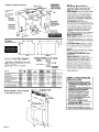
Part No. 43240761883243
IMPORTANT:
Read and save
these instructions.
IMPORTANT:
Installer: Leave Installation
Instructions
with the homeowner.
Homeowner: Keep Installation Instructions
for future reference.
Save Installation Instructions for local
electrical inspector’s use.
30” and 36”
Retractable Downdraft
Vent Systems
@/+\b
Rev. B
Cabinet di
A = cabinet wall
to rear line of
cutout
Allow l/2” from
rear of downdraft
vent to back wall
of cabinet.
See cooktop
manufacturer’s
instructions for
Cutout width:
30” vent-27-l/2”
A
L
T
Left cabinet
wall cutout:
Centerline
is
17-3/16” from
countertop.
\
Use dimensions
for ductwork
cutout location
that applies to
your installation.
rear edge of
cooktop overlaps
edge of downdraft
vent by J/8”.
\
Locate
supply
box at
corner
cutout
dimensions
l-
power
junction
lower right
of cabinet.
x---d
Jt
-i+
JF)j
C
Figure 1
Dimension A: If just a “Max.” dimension
given, that dimension must be used.
Figure 2
Example:
is
*If dimension A is between the “Min.” and
“Max.“: Subtract actual dimension “A” from
‘A Max. y Divide by 2.
Add to ‘B (for A Max.)”
B dimension.
RC8536, 19- l/2” cutout
“A Max.”
Actual “A”
20-l /4”
- 19-l/2”
314” + 2 = 318
B (for A Max.)
+
for required
2-l/2”
3ian
2-7/8” = Required B
dimension
Models
C8200XY/RC8400XY/
k84ooXYQ
RC8536XT *
RC8600XXB/Q
8’.-“‘“”
RC8436XT/RC8436XTW
*
RC8330XTB/RC8430XT/
] RC8430XTW l
SC8630EX and EAW/N/B/Q
[i#ii$$&iijiiiFj
::.::::$g.fg:::::::::::::
I
:,:.:
:.. .ii..
i::ii::~:i:jiiiij 1
;..:
:iii:!!
1
.A..
..:.......
.... ..
........
.
.........
+ziiis
..........
x:;:;:::.:.:.:.:
..:::.
.:.:.:.:i
,......
J@$i’i’i’
::.:.:
.., ....:.:.:.:.:
1
.>:.:: .,.,.,.,.:.:.:.:,:.:.:.
...................,..
,.:
2
s @:jZ
SC8430ERbC8430ERH
SC8536EX/SC8536EXH/
SC&36EXB/SC8536EXQ
;iiiip
...... .........
:~~
.,........................
............................ 19-l 14”
:j:j:~
,:::::Jz@
“.......~........
n.. 20- 1/4”
:.:.:.;:
....:::&gg$
::::::::::::::::::::::::::::::::::::::::::
iiijiiijiiijjiijijijjijijjijiiijijjjjjij~
PO-1/4”
..... ..... .....
.iiiBig3:
,,.,.“,& 20-5/8”
..~.,.,.,.,.~..~.~.,.
&3?
..,...,...........
.:::::.
................,:,.
........:..
.::....
,....
$4.~.
..::i:i: 2&5,8”
:.i~~~~~~~~~
p-5/8”
~~~
..............
:3~::;wj:~:::::::::::::::::::::::::
iiiiiiiiaiis~~~
........,...,.
.....
::::::::,
%:;
,:...:......._.,.,.,
:i:i:i:i:i:i:i:i:~:i:i:i:i:i:i:i:i:i
~~~~~
~
27-1,2~~
2-5/l 6”
3i:~:~:~~~~~~~~~~~~~~~~~:~:~~~:~:~~~:~~:~~~~::
,.......,.,.
.:.:.:.:
.................
:.:...........:::...
, Q’
~~~~~~~~~~~ l-314”
.,...,.
..
iiidi%d~~Sjiii:l27- l/y
..,:,:.:.:.:::::::::::::::::j::::::::::::::::
..............:::::::
,.............
:.:.>>>>:
.,.,...,.,.,.,.,.,.,.,.,.
>:.:.:.:
Retractable downdraft
vent dimensions
26-518”
32-518”
114”
tractable
mt height
I
3O’vent base width 36” vent base width -
27”
3T
26
:
-2-l/8”
Panel A
Important: Observe all governing codes and
ordinances.
Failure to meet codes and
ordinances could lead to fire or electrical
shock.
Proper installation is your responsibility. Make
sure you have everything necessary for
correct installation. It is the responsibility of
the installer to comply with the installation
clearances specified on the model/serial
rating plate. The model/serial
rating plate is
located on the front of the downdraft
vent
above the wiring box cover.
Check location where retractable
downdraft
vent will be installed. The location
should be away from strong draft areas, such
as windows, doors and strong heating vents
or fans. Before making countertop
cutout,
check that retractable
downdraft
vent and
cooktop location will clear cabinet walls,
backsplash, and rear wall studs inside
cabinet.
ALL OPENINGS IN THE WALL OR FLOOR WHERE
RETRACTABLE DOWNDRAFT VENT IS TO BE
INSTALLED MUST BE SEALED.
Electrical ground is required. See “Electrical
requirements, I Panel B.
When installing retractable
downdraft
vent,
the cabinet drawer will need to be removed
and the drawer front installed permanently
to cabinet.
30” min. base cabinet is required. If cabinet
has a drawer, 3-l/2” depth clearance
from
the countertop
to the top of the drawer (or
other obstruction in the base cabinet) is
required.
Note: Retractable
downdraft
vent is installed
directly behind the cooktop. Install
retractable
downdraft
vent first.
This appliance
is not approved for use in
mobile homes.
Cabinet construction:
This appliance
is
designed for use in a cabinet with a depth of
24 inches. The maximum depth of the
overhead cabinet is 13 inches. Overhead
cabinets installed at either side of the
appliance
must be 18 inches above the
cooking surface. See cooktop Installation
Instructions for the minimum distance
between the front edge of the countertop
and front edge of cooktop. The minimum
horizontal distance between the overhead
cabinets is the same as the width of the
installed appliance.
.,...,
i.ifiii~~~~~~~iiiiil:
27-,/p”
.... ....~..........
.....
:::::::::::::::::~:~:::::~:~:~:~:~:
li;i;i;i;i;i;i;i::;i;i;i;j;i;i;i;i;:
33- , ,2”
2 - 1/ 2 ”
i:::::::~:::::~:~:~:~:~:~:~:~:~:~:~
~ii~:
27-11~
.:,:,~~:.:.~:,~:,::::::::::j:j:j:j:j:j:~:~~:
2- 118”
.iiiliiilililiiiiililii:i:i;:i:i:l:i:i:l:~:~~~~
.A..
...............,.,..,,,,,..,,..,,.,.
.................................
~~~P~~~
2-5/1(fy
~
33-l/2”
30” vent width 36” vent width -
Before you start...
WARNING - TO REDUCE THE RISK OF FIRE,
ELECTRIC SHOCK, OR INJURY TO PERSONS,
OBSERVE THE FOLLOWING:
A. Installation Work And Electrical Wiring
Must Be Done By Qualified Person(s) In
Accordance
With All Applicable
Codes
And Standards, Including Fire-Rated
Construction.
B. The combustion airflow needed for safe
operation of fuel-burning
equipment may
be affected by this unit’s operation.
Follow the heating equipment
manufacturer’s
guideline and safety
standards such as those published by the
National Fire Protection Association
(NFPA), and the American Society for
Heating, Refrigeration and Air
Conditioning
Engineers (ASHRAE), and
the local code authorities.
C. When cutting or drilling into wall or
ceiling, do not damage electrical wiring
and other hidden utilities.
D. Ducted fans must always be vented to
the outdoors.
E. If this unit is to be installed over a tub or
shower, it must be marked as appropriate
for the application.
Venting requirements
Parts needed
for installation:
2 conduit connectors
1 wall cap
l
l
Fire Hazard
Do Not obstruct the flow of combustion
and ventilation
air.
Failure to follow this instruction
could
result in fire.
Injury Hazard
To eliminate the risk of burns or fire, avoid
installing cabinet storage above the
cooking surface. If cabinets are already
installed, avoid the use of cabinets while
cooktop is in use.
Reaching over a heated cooking surface
could result in a serious burn.
Use two or more people to move and
install downdraft vent.
Failure to follow these instructions
can
result in back or other injury.
It is the customer’s responsibility:
To contact a qualified electrical installer.
To assure that electrical installation
is
adequate and in conformance
with National
Electrical Code, ANSRNFPA 70 - latest
edition’, and local codes and ordinances.
l
ductwork
Electrical
requfrements
I
/
a4rcc
.
Electrical. Shock Hazard
Electrically
ground downdraft vent.
Failure to follow this mstructron could
result in death, fire or electrical shock.
If codes permit and a separqte grounding
wire is used, it is recommended
that a
qualified electrician
determine that the
grounding
path is adequate.
Do Not ground to a gas pipe.
Check with a qualified electrician
if you are
not sure the downdraft vent is properly
grounded.
Do Not have a fuse in the neutral or
grounding
circuit.
IMPORTANT: Save lnstallcrtion Instructions for
electrical
inspector’s use.
A
Electrical Shock Hazard
Take special care when drilling holes into
the wall for venting or electrical wiring.
Electrical wires may be concealed behind
the wall covering.
Do Not use this downdraft vent with any
solid state fan speed control device.
Failure to follow these instructions
can
result in death. fire or electrical shock.
Tools and materials
needed for installation:
8mm or
3/a'! nut
driver or
ratchet
cable
Fire Hazard
Venting system MUST terminate to the
outside.
Do Not terminate the ductwork in an attic
or other enclosed space.
Do Not use 4” laundry-type
wall caps.
Do Not use plastic-type
ductwork.
Use Only Metal Ductwork.
Failure to follow recommended
venting
instructions
may result in a fire.
w A 120-volt, 60-Hz, AC-only electrical
supply is required on a separate 15ampere
circuit, fused on both sides of the line. A
time-delay
fuse or circuit breaker is
recommended.
The fuse must be sized per
local codes in accordance
with the
electrical rating of the appliance
specified
on the model/serial
rating plate located on
the front of the downdraft
vent above the
wiring box cover.
B
n
THE RETRACTABLE DOWNDRAFT
VENT MUST BE CONNECTED WITH COPPER
WIRE ONLY.
Ductwork needed for installation
is not
supplied. Wall cap is Not provided.
Determine which venting method to use.
Ductwork can extend either through the wall
or roof.
*The length of ductwork and number of
elbows should be kept to a minimum to
provide efficient performance.
*The size of the ductwork should be uniform.
Do Not insfall two elbows together.
*Use duct tape to seal all joints in the
ductwork system.
Use caulking tape to seal the exterior wall or
floor opening around cap.
*Do Not cut joist or stud. If ductwork cutout
falls over a joist or stud, a supporting frame
must be constructed.
*Flexible metal ductwork is Not
recommended.
If it is used, calculate each
foot of flexible metal ductwork as two feet
of straight metal ductwork. Flexible metal
elbows count twice as much as standard
elbows.
NOTE: Make sure there is proper clearance
within the wall or floor exhaust duct before
making cutouts,
l
l
Recommended
duct length
Ductwork length should not exceed the
maximum lengths listed in the ‘Maximum
length of duct system” chart. (See Panel C.)
C
n Wire sizes must conform
to the
requirements
of the National Electrical
Code, ANSI/NFPA 70 - latest edition*, and
all local codes and ordinances.
Wire size
and connections
must conform with the
rating of the appliance.
Island location
D
’
Phillips fl
screwdriver
’
orkevholesaw
screwdriver
n
This downdraft
vent should be
connected
directly to the fused disconnect
(or circuit breaker) through flexible,
armored or non-metallic
sheathed, copper
cable. Allow some slack in the cable so the
downdraft
vent can be moved if servicing is
ever necessary.
Figure 3
E
n
A U.L.-listed, l/2” conduit connector
must be provided at each end of the
power supply cable (at the downdraft
vent
and at the junction box).
Built-in cabinet
location
F
n
A wiring diagram is located on the
downdraft
vent base above the wiring box
cover.
L
@
Copies of the standard listed above
from.
*National
Fire Protection Association
Batterymarch
Park
Quincy, Massachusetts
02269
‘I
safety
glasses
Parts supplied v
for installation:
l
l
l
l
2 end caps
2 lower support legs
2 overcounter
mounting brackets
2 undercounter
mounting brackets
Panel B
l
l
l
l
1 bag of fasteners
I metal cover
1 backdraft
damper
literature package
Electrical
own vent
may be obtained
Figure 4
connection
1. Cut a l-l /2” hole in floor or side of
cabinet for power supply wire. The hole cut
for electrical wiring through a wood cabinet
should be sanded until smooth. A grommet
(Part No. 302797) must cover the hole cut
for the electrical wiring through a metal
cabinet.
2. Run flexible armored or nonmetallic
sheathed copper cable from fused
disconnect
circuit breaker or junction box
through the cabinet hole to the downdraft
vent location.
3. See installation steps to connect
supply cable to downdraft
vent.
power
Built-in cabinet
location
Figure 5
Ductwork installed under a concrete slab using
PVC sewer pipe.
Now start...
vent in kitchen.
With downdraft
1
n
Put on gloves and safety glasses.
Place cardboard
or another form of
protection
on top of a flat surface where
you can easily assemble the downdraft
vent system. Remove parts packages,
downdraft
vent and blower box from
carton. Remove all shippina materials, tape
and protective
film fro’& downdraft
vent
and blower box.
Optional ductwork installed under a concrete slab
into a window well.
Do not vent a gas cooktop into a window well,
transition
6” round PVC
12” minimum
6” round metal duct
concreie
slab
6” round
T
6” min.
Tiahtlv
‘-G----I
I
oock
PVC sewer
pipe elbow
r --.-
6” rouhd
gravel or sand
PVC
completely
around pipe.
coupling
Seal the space between the outside of wall
cap inlet inside of PVC coupling with
caulking metal.
Maximum
length
of ductwork
system
For best performance,
use no more than
three 90” elbows. If more than one elbow is
used, make sure that there is a minimum of
24 inches of straight duct between any two
elbows. Do Not install two elbows together.
It is recommended
that you use round duct
instead of rectangular
duct, especially if
elbows are required. If rectangular
duct is
required, it should be transitioned
to 6”
round duct as soon as possible.
Determining
you need
the length
of system
To calculate
the length of system you need,
add the equivalent
feet for each duct
piece that will be needed. See example for
6” round ductwork system.
6” round ductwork
2
w Attach one
overcounter
mounting bracket to
each side of the
downdraft
vent with
flange side out.
3
w Attach supper? legs to side of
downdraft
vent with two screws in each
Do Not tighten screws.
leg.
Injury Hazard
Use two or more people to move and
safely install vent system.
Failure to follow this instruction
can result
in back or other injury.
bracket for
real venting
\
4
w Carefullv insert downdraft
vent into
countertop
cut&t.
Two people are
recommended
to support the weight of the
downdraft
vent during lifting. Check that
downdraft
vent is parallel to side of cutout
and that mounting brackets overlap
countertop.
system
6ft.-4
lb
I-wallcap
8 feet straight
2 - 90” elbows
Transition
Length
Maximum
length
=
=
=
=
feet
feet
feet
feet
feet
of 6” system =
Recommended
0
8
10
4.5
22.5
standard
= 25 ft.
fittings
3-l/$x
lO”to6”
90” elbow = 5 ft.
6”f;63-1/4”xlo”
90” elbow = 9 ft.
d. Remove screws attaching
brackets to
each side of blower. Reposition brackets on
blower as shown. Then reinstall screws.
e. Reinstall blower in blower box with mouth
of blower pointing out open side of blower
box. Secure blower to blower box with 6
Phillips-head screws.
NOTE: Square metal frame attached
to
mouth of blower must be installed for
proper operation.
f. Attach metal cover from parts bag over
down-venting
knockout in blower box.
Remove rear knockout cover on back of
vent base.
g. Reconnect
blower wiring cable. Secure
wiring cable in 2 black plastic clips inside
vent base. Reattach blower box to
downdraft
vent base with 4 hex nuts.
w Move support legs down against
cabinet floor. PI&e a le;el against-front
of
downdraft
vent base and adjust until
downdraft
vent is level vertically. Use a
pencil to mark the top of each leg on face
of downdraft
vent. Then mark location of
support leg mounting holes on cabinet
floor. Remove downdraft
vent from cutout.
Drill starter holes at each mounting screw
location on cabinet floor. Align top of legs
with pencil marks on face of downdraft
vent. Tighten screws in legs.
..-...-.
...-...-.-.-.-.-.-..i
..:::::
:i:: .:::::::;
..-.-.-.-..-...
:
..i-I~~~
.::.:::.:>.:::;
.-:.. ~~~ ...~~~:-.
3-l/&x
10”
to 6” = 4.5 ft.
6
H Determine which direction (down or
rear) ductwork will need to run from blower
duct when installed in cabinet.
Down venting:
Downdraft
vent is shipped with blower in
down venting position so no modification
is
required. Go to Step 7.
left or right venting:
a. Remove 4 hex nuts that attach blower
box to downdraft
vent base. Remove
blower box.
b. Rotate blower box 90” to left or right so
that vent blower is repositioned
in the
direction needed.
c. Reattach blower box to downdraft
vent
base with 4 hex nuts.
Rear venting:
a. Remove 4 hex nuts that attach blower
box to downdraft
vent base. Remove
blower box.
b. Note how wiring cable is installed under
plastic clips inside vent base. Then carefully
remove wiring cable from plastic clips.
Disconnect
blower wiring cable.
c. Remove 6 Phillips-head
screws attaching
blower to blower box. Remove blower.
If blower box is removed from vent base,
check that wiring cable is properly secured
in plastic clips.
7
w Attach backdraft
damper over
blower box knockout with 2 Phillips-head
screws.
8
PO; ;,lbow
Panel
C
n
Remove the 2 Phillips-head screws
attaching
appliance
wirini box cover.
Determine which direction (rear or down)
electrical
connection
will need to run from
appliance
wiring box. Knock out rear or
lower wiring opening in wiring box.
b
6.
Numbers
correspond
to steds.
In jury Hazard
Use two or more people to move and
safely install vent system.
Failure to follow this instruction can result
in back or other injury.
When attaching
undercounter
bracket to
underside of countertop:
Do Not drill into countertop
surface.
Check that mounting screws are proper
length and will not go through countertop
surface when tightened in place.
10
9
n
Insert downdraft
vent into
countertop
cutout. Two people are
recommended
to support the weight of the
downdraft
vent during lifting. Position
downdraft
vent so it is centered
in cutout
and parallel to edge of cutout. Check that
downdraft
vent is level vertically
Then
fasten lower support legs to cabinet floor
with screws. Snap end caps over top of
mounting brackets.
Attach one undercounter
bracket on front upper right
corner of downdraft
vent with slot over vent
mounting hole and flange against
countertop.
Attach other bracket to left
side of downdraft
vent. Carefully drill starter
holes through undercounter
mounting
brackets into underside of countertop.
Insert appropriate
length screws into holes
and tighten brackets to countertop.
n
Top corners of filter frame
must press against
microswitch
behind filter.
,
ON/OFF
, button
n
Turn power supplv on. Push the
button on the top of the do&draft
vent.
Retractable
section of downdraft
vent will
rise and blower will start. Turn the control
knob on side of vent to check the
operation
and speed of blower.
If blower does not operate:
l Check
that filter frame is pressed in as far
as it will go.
l Check
that circuit breaker is not tripped
or house fuse blown.
l Disconnect
power source and check that
wire connections
have been made
correctly.
13
n
Connect ductwork to blower
Position ductwork to avoid wall studs and
floor joists. Complete
all ductwork.
Use duct
tape to seal all joints. Ductwork must end
with a wall or roof cap.
14
n
Install cooktoo accordina
to
manufacturer’s
instructions. Check t6at rear
edge of cooktop overlaps edge of
retractable
downdraft
vent by 3/8”.
11
’ Disconnect power SUDP~Y. Thread
the power supply cable through the
knockout opening in the wiring box.
Connect the white wires together with a
twist-on wire connector.
Connect the black
wires together with a twist-on wire
connector.
Attach the green (or green and
yellow) grounding wire to eyelet with green
grounding screw. Reattach the wiring box
cover.
Keep Installation
Instructions close
to downdraft vent for easy reference.
( Congratulations
! )
~~~:~~;~v~
The instructions
will make
Panel D
_-
,
reinstalling
Use & Care
Information
The retractable
downdraft
vent system is
designed to remove smoke, cooking vapors
and odors from the cook-top area. For the
best results, the vent should be operating
before cooking is started. If you use large or
tall utensils, place them on the large rear
element or burner surface. A higher heat
setting than normally used may be needed
when the downdraft
vent is operating.
Operating
downdraft
vent
Push button on top of downdraft
vent.
Retractable
section of downdraft
vent will
rise and blower will begin to vent. Turn knob
on side of downdraft
vent to adjust the
setting to the amount of venting you need.
The knob has infinite settings. Place cooking
utensils on cooking surface and turn
cooking unit on. When cooking is complete,
turn cooking unit off, remove utensils from
cooking surface, and push button on top of
retractable
downdraft
vent. The blower will
turn off and the retractable
section of the
vent will return to the closed position.
Cleaning
WARNING - TO REDUCE THE RISK OF FIRE,
ELECTRIC SHOCK, OR INJURY TO PERSONS,
OBSERVE THE FOLLOWING:
A. Use this unit only in the manner intended
by the manufacturer.
If you have any
questions, contact the manufacturer.
8. Before servicing or cleaning unit, switch
power off at service panel and lock
service panel to prevent power from
being switched on accidentally.
WARNING - TO REDUCE THE RISK OF A
RANGE TOP GREASE FIRE:
A. Keep fan, filter and grease laden
surfaces clean.
B. Always turn hood ON when cooking at
high heat.
C. Use high settings on range only when
necessary. Heat oil slowly on low to
medium setting.
D. Don’t leave range unattended when
cooking.
E. Always use cookware and utensils
appropriate for the type and amount of
food being prepared.
WARNING - TO REDUCE THE RISK OF
INJURY TO PERSONS IN THE EVENT OF A
RANGE TOP GREASE FIRE, OBSERVE THE
FOLLOWING:
A. SMOTHER FLAMES with a close-fitting
lid, cookie sheet, or metal tray, then
turn off the burner. BE CAREFUL TO
PREVENT BURNS. If the flames do not
go out immediately
EVACUATE AND
CALL THE FIRE DEPARTMENT.
B. NEVER PICK UP A FLAMING PAN - You
may be burned.
C. DO NOT USE WATER, including
wet
dishcloths or towels - a violent steam
explosion will result.
D. Use an extinguisher
ONLY if:
1. You know you have a Class ABC
extinguisher,
and you already know
how to operate it.
2. The fire is small and contained
in the
area where it started.
3. The fire department
is being called.
4. You can fight the fire with your back
to an exit.
Panel E
Surface of downdraft vent: Clean with soap
and water. Do Not use scouring powder or
abrasive solutions.
Filter: Frequently remove and clean the
filter in the retractable
section of the
downdraft
vent. This will improve the
operating
efficiency
of the downdraft
vent
system.
1. Remove the filter and clean it in a hot
detergent
solution. Care should be taken
when washing the filter to avoid bending
the frame.
Do Not use the downdraft vent when
the filter is not in place.
2. Reinstall the clean filter into the opening,
making sure that the filter is pushed in as
far as it will go. Filter frame must depress
the microswitch
in the center of the
opening.
Note: Downdraft
vent will not operate if
filter is removed or not in proper position.
If retractable
downdraft vent does not
operate after clean filter has been
reinstalled:
When the filter is removed, the microswitch
behind the filter is activated.
This safety
feature stops the blower and raising
mechanism
until the filter is properly
installed.
To be sure the downdraft
vent operates,
install filter with both locking handles fully
locked.
Note: If both handles are not fully locked,
the vent may retract, but not raise back up.
locking
handles
If retractable
downdraft vent does
not operate...
l
l
l
l
If you need
assistance...
The Whirlpool Consumer Assistance Center
will answer any questions about operating
or maintaining
your retractable
downdraft
vent not covered in the Installation
Instructions. The Whirlpool Consumer
Assistance Center is open 24 hours a day,
7 days a week. Just dial l-(800) 253-l 301 the call is free.
When you call, you will need the
retractable
downdraft
vent model number
and serial number. Both numbers can be
found on the model/serial
rating plate
located on the front of the downdraft
vent
above the wiring box cover.
Check that filter is pressed in as far as it will
w
Check that top corners of filter frame are
pressed against microswitch
located
behind filter.
Check that the circuit breaker is not
tripped or the house fuse blown.
Disconnect
power source and check that
wire connections
have been made.
Whirlpool@ Downdraft Vent WarrantyL
LENGTH OF WARRAN;
LIMITED ONE-YEAR WARRANTY
From Date of Purchase
WHIRLPOOL WILL PAY FOR
Replacement
parts for any parts of your downdraft
filters) which are defective
in materials
If you need service...
vent (except
or workmanship.
In the event that your Whirlpool appliance
should need service, call the dealer from
whom you purchased
the appliance
or a
Whirlpool-authorized
service company.
A
Whirlpool-authorized
service company
is
listed in the Yellow Pages of your telephone
directory under “Appliances
- Household
- Major - Service and Repair. I
WHIRLPOOL WILL NOT PAY FOR
A. Any labor costs incidental
to the replacement
of defective
parts.
B. Consumable
parts such as filter.
C. Service calls to:
1. Correct the installation of the downdraft
vent.
2. Instruct you how to use the downdraft
vent.
3. Replace house fuses or correct house wiring.
D. Repairs when downdraft
vent is used in other than normal, single-family
household use.
E. Pickup and delivery. This product is designed to be repaired in the home.
F. Damage to downdraft
vent caused by accident,
misuse, fire, flood, act of God or use of products
not approved
by Whirlpool.
You can also obtain the service company’s
name and telephone
number by dialing,
free, within the continental
United States,
the Whirlpool Consumer Assistance Center
telephone
number, l- (800) 253-1301, A
special operator will tell you the name and
number of your nearest Whirlpoolauthorized service company.
WHIRLPOOL CORPORATION SHALL NOT BE LIABLE FOR INCIDENTAL OR CONSEQUENTIAL DAMAGES.
Some states do not allow the exclusion or limitation of incidental
or consequential
damages
so this
limitation or exclusion may not apply to you. This warranty gives you specific legal rights, and you may also
have other rights which vary from state to state.
Outside the United States, a different warranty may also apply. For details, please contact your franchised
Whirlpool distributor or military exchange.
Part No. 43240761883243 Rev. B
01996 Whirlpool Corporation
Prepared
by Whirlpool
Co$&tion,
Benton Harbor,
Michigan
Maintain the quality built into your Whirlpool
appliance
- call a Whirlpool-authorized
service company.
49022
Printed in U.S.A.