1
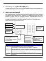
SigNET 200/300
User Guide
Warning: While this system is an advanced design integrated security system, it does not offer guaranteed protection against
burglary, fire or other emergency. Any alarm system, whether commercial or domestic, is subject to compromise or failure to
warn for a variety of reasons.
Therefore, good installation practices, thorough testing, and regular maintenance by the installation company and frequent
testing by the user are essential to ensure continuous satisfactory operation of the system. It is recommended that the
installation company offer a maintenance program and instruct the user with the correct procedure for use and testing of the
system.
COPYRIGHT NOTICE
Copyright © 2006 Europlex Technologies Ltd (hereby referred to as Europlex). All rights reserved. No part of this
publication may be reproduced, transmitted, stored in a retrieval system, or translated into any language or computer
language in any form or by any means electronic, mechanical, magnetic, optical, chemical, manual, or otherwise without
the prior written permission of Europlex.
Disclaimer: Europlex make no representations or warranties with respect to the contents hereof and specifically disclaim
any implied warranties of merchantability or fitness for any particular purpose. Further Europlex reserve the right to revise
this publication and to make changes from time to time in the contents hereof without the obligation of Europlex to notify
any person of any such revision.
All products or services mentioned in this manual are covered by the trademarks, service marks, or product names as
designated by the companies who market those products.
E-LAB-1543 SigNET 200/300 User Guide, Issue 01, Sept 2006
When changing or installing a expanders on the SigNET 200/300 system always ensure that
all anti-static precautions are adhered to while handling connectors, wires, terminals and
PCB’s.
Europlex Technologies [IRL] Ltd.
Clonshaugh Business and Technology Park,
Clonshaugh,
Dublin 17,
Ireland.
Tel: +353 (0) 1 2500500
Fax: +353 (0) 1 2500592
E-Mail: [email protected]
Company Web Site address: www.europlex.ie
Technical Support: [email protected]
Page 2
Europlex Technologies (UK) Limited
Innovation Centre,
Cranfield University Technology Park,
University Way, Cranfield,
Bedfordshire, MK43 0BT,
United Kingdom.
Tel. +44 (0) 8700 600 140
Fax. +44 (0) 8453 307 240
Table of contents
1.
Introducing the SigNET 200/300 System ...................................................4
2.
How to use your Keypad ............................................................................4
2.1
How to use the Keypad programming interface......................................................................................5
2.2
Data entry on the SigNET Keypad..........................................................................................................6
3.
Intruder alarm Operation ............................................................................7
3.1
Entering User Programming ...................................................................................................................9
3.2
Setting the System -FULLSET................................................................................................................9
3.3
Setting the System – PARTSET A..........................................................................................................9
3.4
Setting the System – PARTSET B..........................................................................................................9
3.5
Unsetting the System ............................................................................................................................10
3.6
Fail to set...............................................................................................................................................10
3.7
Force Setting the System......................................................................................................................10
3.8
Inhibiting a Zone....................................................................................................................................11
3.9
Restoring an alert..................................................................................................................................11
3.10
Isolating a Zone or fault ........................................................................................................................12
3.11
Setting the Time and Date ....................................................................................................................12
3.12
Performing Tests on the system ...........................................................................................................13
3.13
Viewing the Event Log ..........................................................................................................................13
3.14
Allowing Engineer Access.....................................................................................................................13
Page 3
1. Introducing the SigNET 200/300 System
The SigNET 200/300 system must be installed by a qualified installation engineer. When the installation of the
SigNET 200/300 has been completed, the engineer will provide you with a user password that will enable you
to SET/UNSET and configure your system as required.
2. How to use your Keypad
The SigNET Keypad is a wall mounted programming interface unit that allows you to enter User programming
menus (password protected), and perform operational procedures (arm/disarm) on the system. The keypad
unit includes an integral front tamper switch and a 2 line x 16 character display. Three LED’s provide
information on AC power, system alerts and communications status. The Keypad features an easy to use
Navigation key (Navi-Key) to assist you in locating your required programming options and two context
sensitive soft keys (left and right) allowing you to select the required menu or program setting.
The SigNET Keypad may be factory fitted with a Portable ACE (PACE) proximity device reader and/or a
wireless module for the enrolment of wireless sensors.
AC Mains LED
System Alert LED
01 Dec 06 17:00
12 x Alphanumeric
Keys for numeric
and text data
entry.
Comms LED
Portable ACE
receiver area
Licence Details
Programming keys
1 x Navi-Key (Multi-functional
navigation key)
2 x context sensitive programming
keys (Left & Right)
Installer Contact Number
Installer Name
Installation Date
Pull down Information
Tab.
The installer contact and
licence details are
available by pulling down
the information tab
LED Status Indicators
AC Mains LED
(Green)
This LED Indicates the presence, or failure of, the mains supply.
LED FLASHING - AC Mains fault detected. LED STEADY – AC Mains OK
System Alert
(Yellow)
This LED Indicates the occurrence of a system alert. When flashing, a text message on
the display will indicate the location and nature of the alert. If the system is SET, then NO
indication will be given of system alerts.
LED FLASHING - System Alert detected. LED OFF – No Alert detected
Comms LED
(red)
This LED Indicates the status of the EBUS communications when in FULL ENGINEER
programming.
Page 4
2.1 How to use the Keypad programming interface
TOP LINE OF DISPLAY
BOTTOM LINE OF DISPLAY
During the IDLE state this line will show the current
date and time.
During the IDLE state this line will be blank.
During Programming mode this line will show one of
the following:
The programming feature to be selected
The current setting of the selected feature
During Programming mode this line will show the 2
options available to the user/Engineer. These
options will be aligned over the left and right soft
keys for selection as required.
During an alert condition this line will show
The nature of the current alert
LEFT SOFT KEY
RIGHT SOFT KEY
This key is used to select the
option presented on the left side of
the bottom line of the display.
Possible values are:
- EXIT to exit programming
- BACK to go back to the
previous menu
This key is used to select the
option presented on the right side
of the bottom line of the display.
Possible values are:
- SELECT to select the menu
displayed on the top line
- ENTER to enter the data
displayed on the top line
- SAVE to save a setting
MULTI-FUNCTION NAVIGATION KEY (NAVI-KEY)
OK - The OK button serves as a SELECT key for the menu option that is displayed on the top line of the
display and also as an ENTER/SAVE key for data that is displayed on the top line of the display.
- In programming mode, the right arrow key will advance the user through the menus in the same way as
pressing the SELECT option ( right soft key). When no more menu options can be selected, this key has
no function. In data entry mode, this key will advance the cursor one position to the right.
- In programming mode, the left arrow key will return the user to the previous menu level. Pressing this
key while in the top menu level will exit the user from programming. In data entry mode, this key will
move the cursor one position to the left.
- In programming mode, the Up arrow key will move the user to the previous programming option in the
same menu level. Continually pressing this key will scroll through all of the programming options
available on the current menu level. In Text entry mode, pressing this key over a lower case character
will change the character to upper case.
- In programming mode, the down arrow key will move the user to the next programming option in the
same menu level. Continually pressing this key will scroll through all of the programming options
available on the current menu level. In Text entry mode, pressing this key over an upper case character
will change the character to lower case.
Page 5
2.2 Data entry on the SigNET Keypad
Entering data and navigating the menus on the Signet Keypad is facilitated through the use of the
programming interface. The use of the interface for each type of operation is detailed below.
2.2.1 Entering Numeric values
In Numeric Input mode, you can only enter numeric
digits (0 – 9) . This type of
Pressing the Left & Right arrow keys move the position
of the cursor one character to the left and right
respectively. To exit from the feature without saving
press the BACK menu key.
To save the programmed setting press the ENTER
menu key or the OK key.
2.2.2 Entering Text
In Text Input mode, you can enter alphabetic characters
(A-Z) or numeric digits (0 – 9). To enter an alphabetic
character simply press the relevant key the required
number of times. To enter a digit , hold the relevant key
down for 2 seconds and release.
By pressing the Left and Right arrow keys you can
move the position of the cursor one character to the left
and right respectively. To change the case of an
alphabetic character, simply press the up or down arrow
keys when the character is highlighted by the cursor.
To exit from the feature without saving press the BACK
menu key.
To save the programmed setting press the ENTER
menu key or the OK key.
Pressing the hash (#) key toggles between upper and
lower case character entry for all subsequent characters.
Press the star key(*) to delete character to the left of the
cursor.
2.2.3 Selecting a programming option
In navigation mode, the Engineer/User simply selects
one of a number of pre-defined programming options
from a list. Pressing the Up & Down arrow keys scrolls
through the list of options available for selection. To exit
from the feature without saving press the BACK menu
key.
To save the selected option press the SAVE menu key
or the OK key.
If X-10 has been set up on your system by the installation engineer, then an X10 device may be
activated by pressing the hash (#) key followed by the device number.
Note
Page 6
3.
Intruder alarm Operation
The operational features of the SigNET 200/300 system are described below. Your installation engineer will
inform you of the user rights that have been assigned to your user profile. The settings that relate to the
operation of these features are accessible from engineer programming (Default code 1111).
Operation
Description
UNSET
The Unset operation unsets the alarm. This menu option will only be presented on the
keypad after an alarm has been activated and a valid user code has been entered.
RESTORE
FULLSET
The restore operation will restore an alert condition on the system and clear the alert
message associated with that alert condition. An alert condition can only be restored
after the zone(s) or fault(s) that triggered the alert condition have been restored to
their normal operating state and the RESTORE option in user programming is
selected for that zone.
The fullset operation fully sets the alarm system and provides full protection to a
building (opening of any alarm zones will activate the alarm).
On selecting Fullset, the buzzer will sound and the keypad display will count down the
Exit time period. Please exit the building before this time period has expired. When
the exit time period has expired the system is set and opening of Entry/Exit zones will
start the Entry timer. If the system is not Unset before the Entry timer expires then
the alarm is activated.
FORCESET
PARTSET A
The forceset option is presented on the Keypad display when you attempt to set the
system while an alarm zone is faulty or still open. (The top line of the display will
show the open zone). Selecting this option will set the alarm and inhibit the zone for
that set period.
This mode provides perimeter protection to a building while allowing free movement
through the exit and access areas.
Zones which have been classified as EXCLUDE A will remain unprotected in this
mode. By default there is no exit time - the system sets instantly on selection of this
mode. An exit timer can be applied to this mode by enabling the Partset A Timed
variable.
PARTSET B
This setting mode applies protection to all zones except those, which have been
classified as EXCLUDE B.
By default there is no exit time, with the system setting instantly on selection of this
mode. An exit timer can be applied to this mode by enabling the Partset A Timed
variable.
Page 7
Menus
INHIBIT
These Menu options are only available to Standard or Manager Type Users.
Inhibiting a zone will de-activate that zone for one alarm set period. Only Alarm,
Entry/exit, Fire exit and Line zone types can be inhibited.
This is the preferred method of de-activating a faulty or open zone as the fault or
open condition will be displayed on the keypad each time the system is being set to
remind the user to attend to that zone.
ISOLATE
Isolating a zone will de-activate that zone until such time as the zone is De-isolated
again. All zone types on the SigNET 200/300 can be isolated.
Use of this feature to de-activate faulty or open zones should be considered carefully,
as once a zone is isolated, it will be ignored by the system and may very well be
overlooked completely when setting your system, thus compromising the security of
your building or premises.
SET DATE /
TIME
This menu option allows you to program the time and date on the system. Please
ensure that the time and date information is accurate as these fields are presented in
the event log when reporting system events.
TEST
This menu option provides you the following test features.
1. Bell test
The Bell test will activate the external bells, the strobe, the internal bells and the
buzzer in turn for 5 seconds approximately to ensure their correct operation.
2. Walk Test
A walk test allows you to test the operation of all of the alarm sensors on your
system. On selecting this option, the keypad presents the number of zones to test on
the system. Simply activate each alarm sensor (by opening the door or window) and
check for an audible beep at the Keypad. Isolated and inhibited zones are not
included in the walk test.
3. Audible Options
This option allows you to select which devices will activate during the walk test and
which will be silent.
EVENT LOG
This menu option will display the most recent event on the keypad display. The event
log will detail the time and date for each logged event.
CHIME
All zones that have the CHIME attribute set will generate a short burst of audible tone
on the keypad buzzer when they are opened ( while the system is unset).
This menu option allows you to enable or disable the chime feature on all zones.
CHANGE
CODE
This menu option allows you to change your user code.
SETUP SMS
This feature allows you to setup the SMS messaging service if you have a modem
installed on your system. Please consult your installation engineer when
programming this option.
GRANT
ACCESS
This option allows you to grant access to manufacturer and engineer programming.
Page 8
3.1 Entering User Programming
To access user programming simply enter the user code given to
you by the installation engineer on the keypad. As digits are being
entered they will be displayed as asterixes on the LCD and the left
function key will present the option QUIT.
Press the QUIT key to abort user programming and return to normal
operation mode.
****
QUIT
OK
3.2 Setting the System -FULLSET
On entering a Valid User Code the user will be presented with the
FULLSET option. The FULLSET operation is used to perform a
complete arming of the system.
The FULLSET option provides the following functionality
-
Full protection to a building (opening of alarm zones will
activate the alarm)
opening of Entry/Exit zones will start the Entry timer. If the
alarm is not Unset before the Entry timer expires then the
alarm is activated.
-
As soon as the user selects the FULLSET option the second line of
the display will countdown the exit timer and the buzzer will sound
to indicate that the user should exit the building. When the system
has been fully set the LCD will display FULLSET on the bottom line
for approximately 10 seconds.
FULL SET
EXIT
SELECT
01 SEP 06 17:00
SETTING 45 SECS
01 SEP 06 17:00
FULLSET
3.3 Setting the System – PARTSET A
The PARTSET A option provides the following functionality
Perimeter protection to a building while allowing free
movement through the exit and access areas.
- Zones which have been classified as EXCLUDE A remain
unprotected in this mode
- By default there are no Exit times associated with PARTSET A
and the alarm is activated instantly on selection of this mode.
To select PARTSET A, enter user programming, scroll down to the
PARTSET A option and press SELECT.
PARTSET A?
EXIT
SELECT
-
3.4 Setting the System – PARTSET B
The PARTSET B option provides the following functionality
-
Perimeter protection to a building while allowing free
movement through the exit and access areas.
Zones which have been classified as EXCLUDE B remain
unprotected in this mode.
01 SEP 06 17:00
PARTSET A
PARTSET B?
EXIT
SELECT
01 SEP 06 17:00
PARTSET B
By default there are no Exit times associated with PARTSET B
and the alarm is activated instantly on selection of this mode.
Partset A and Partset B modes can be configured to use the Exit timer by enabling the PARTSET
TIMED Variables in Engineer Programming .
Note
Page 9
3.5 Unsetting the System
To UNSET an armed system enter your user code on the keypad.
The Keypad display will prompt the user to unset the system. To
Unset the system press the SELECT key.
UNSET?
EXIT
SELECT
The keypad display will indicate that the system is unset on the
bottom line of the display for approximately 5 seconds. After this
time has elapsed the bottom line will be cleared.
01 SEP 06 17:00
UNSET
If the alarm has been activated, then on entering your user
code all active bells and strobes will be turned off and the
message – PANEL DISARMED – will be displayed on the
keypad for approximately 5 seconds.
PANEL DISARMED
The source of the alarm condition will then be displayed on
the keypad and the Alert LED will flash. The keypad will
continue to display the alert until you restore the alert.
(See 3.9 - Restoring an alert).
ALARM ZONE 2
FIRST ZONE
3.6 Fail to set
The user will fail to set the system if an open or fault
condition is detected on any of the alarm zones when
selecting the FULLSET or PARTSET A/B options. The
Keypad Display will indicate this by flashing the text
FAILED TO SET on the top line of the display followed by
the Zone number and description.
FAILED TO SET
To allow setting of the system, locate the zone and close
or fix the fault. Repeat the FULLSET or PARTSET
operation.
ZONE 3
KITCHEN
3.7 Force Setting the System
If the user has the rights to perform a FORCE SET then
the system can be forced to set while an alarm zone is still
open. This operation will simply inhibit the open zone and
set the system as normal.
If the user has the right to Force set the system and an
alarm zone is open, then on selecting a FULLSET or
PARTSET option, the keypad buzzer will beep and the first
line of the display will indicate the open zone. The user will
be presented with the options to QUIT or FORCE.
ZONE X OPEN
QUIT
FORCE
FORCED SET?
BACK
SELECT
QUIT -
Selecting this key will abort the attempt to set
the system and return the user to user
programming.
FORCE - Selecting this option will inhibit the open zone
and force the system to set.
Check with your installation engineer if you have been given the ability to force set the system.
Note
Page 10
3.8 Inhibiting a Zone
The user has the option to manually inhibit a Zone on the system
from the keypad. The Inhibit operation is active for only one alarm
set period.
•
Enter your User programming code on the keypad, scroll down
to the MENUS option and press SELECT.
•
The INHIBIT option will be displayed on the Keypad. Press the
SELECT key.
•
Scroll down to the ZONES menu option and press SELECT.
•
A list of zones on the system will be displayed. Select the
required zone and toggle the setting from NOT INHIBITED to
INHIBITED using the up/down arrow keys.
•
Press the SELECT key and exit user programming.
MENUS
EXIT
SELECT
INHIBIT
EXIT
SELECT
ZONES
BACK
SELECT
ZONE 1
BACK
SELECT
INHIBITED
BACK
SELECT
Only the Alarm, Exit/Entry, Fire exit and Line Zone types can be inhibited on the
SigNET system. All other zone types will not be displayed in the inhibit menus.
Note
3.9 Restoring an alert
Alert conditions on the SigNET 200/300 are indicated on the
keypad by a flashing yellow Alert LED ( See 2 - How to use your
Keypad ) and by activation of the buzzer. Text on the keypad
display will indicate the location and nature of the alert condition.
The ability of a user to restore alerts on the SigNET 200/300
system is programmed by your installation engineer. To restore an
alert condition that is triggered by a zone opening, locate the open
zone ( displayed on the keypad display) and restore the alarm
sensor to it’s normal state (Close the door or window).
At the keypad enter your user code and select the RESTORE
menu option. The zone that caused the alert will be displayed on
the top line of the display. Press the right menu key to restore the
alert. The message - ALL ALERTS RESTORED - will be displayed
and the flashing Alert LED will turn off.
For system or communications type alert conditions (Mains failure
or EBUS disconnect), locate the source of the alert condition and
check that all wires and cables are properly connected. For a
tamper alert, ensure that the lids on all enclosures and devices are
correctly closed. If you cannot restore the physical fault to it’s
normal operating state please contact your installation engineer.
You may still continue to operate your alarm system by either
inhibiting or isolating the fault condition.
ALARM ZONE 2
Sitting Room
RESTORE
EXIT
SELECT
Sitting Room
QUIT
RESTORE
ALL ALERTS
RESTORED
Page 11
3.10 Isolating a Zone or fault
The user has the option to manually isolate a zone or fault on the
system from the keypad. Isolating a zone will remove that zone
from the system until such time as the user de-isolates it. To
isolate a zone:
•
Enter your User programming code on the keypad, scroll
down to the MENUS option and press SELECT.
•
Scroll down to the ISOLATE option using the up&down
arrow keys.
•
Press the SELECT key.
•
Scroll down to the ZONES menu option and press
SELECT.
•
A list of zones on the system will be displayed. Select the
required zone and toggle the setting from NOT ISOLATED
to ISOLATED using the up/down arrow keys.
•
Press the SELECT key and exit user programming.
MENUS
EXIT
SELECT
ISOLATE
EXIT
SELECT
ZONES
BACK
SELECT
ZONE 1
BACK
SELECT
ISOLATED
BACK
SELECT
3.11 Setting the Time and Date
The user has the option to manually enter the date and time on
the system. The time and date information is displayed on the
keypad and browser and is used on the time related
programming features.
To program the Date and Time:
•
Enter your User programming code on the keypad, scroll
down to the MENUS option and press SELECT.
•
Scroll down to the SET DATE/TIME option using the
up&down arrow keys.
•
Press the SELECT key.
•
The date will be displayed on the top line of the display. To
enter a new date simply press the required numeric keys
on the keypad. To move the cursor to the left and right
press the left and right arrow keys. On editing the date as
required press the ENTER key to save. If an attempt is
made to save an invalid date value, the text INVALID
VALUE is displayed for 1 second and the user is prompted
to enter a Valid date.
•
Page 12
The time will be displayed in 24hour format on the top line
of the display. To enter a new time press the required
numeric keys on the keypad. To move the cursor to the left
and right press the left and right arrow keys. On editing the
time as required press the ENTER key to save. If an
attempt is made to save an invalid time value, the text
INVALID VALUE is displayed for 1 second and the user is
prompted to enter a Valid time.
MENUS
EXIT
SELECT
SET DATE/TIME
EXIT
SELECT
DATE 01/09/2006
BACK
ENTER
TIME
BACK
11:12:35
ENTER
3.12 Performing Tests on the system
The user has the option to perform simple tests on the system to
determine if the bells, buzzers and other audible devices are
operating correctly.
To perform a test on the system:
•
Enter your User programming code on the keypad, scroll
down to the MENUS option and press SELECT.
•
Scroll down to the TEST option using the up&down arrow
keys and press the SELECT key.
•
The User will be presented with the option to select a
BELL TEST, WALK TEST or test the AUDIBLE OPTIONS.
•
On selecting BELL TEST, the user will be presented with
the options - external bells, strobe, internal bells and
Buzzer. On selecting these options each one will sound in
turn to verify that the device is operating correctly.
•
On Selecting WALK TEST, the user can test the operation
of each alarm device by activating the device and checking
to hear if an audible beep is given at the keypad.
MENUS
EXIT
SELECT
TEST
EXIT
SELECT
BELL TEST
BACK
ENTER
EXT BELLS
BACK
NEXT
•
3.13 Viewing the Event Log
The user can view a list of the most recent events on the
system by selecting the event log option. The most recent
event will be displayed on the bottom line of the display with all
previous events displayed for 1 second in turn.
To view the event log on the keypad:
•
Enter your User programming code on the keypad, scroll
down to the MENUS option and press SELECT.
•
Scroll down to the EVENT LOG option using the up/down
arrow keys and press the SELECT key.
•
The Keypad display will show the most recent event
logged on the system on the bottom line with all previous
events lashed for a 1 second period in turn.
•
To view an event from a particular date, enter the date on
the numeric keys.
MENUS
EXIT
SELECT
EVENT LOG
EXIT
SELECT
01 SEP 06 17:00
INHIBIT: ZONE 3
•
3.14 Allowing Engineer Access
A user can allow an engineer to access to the system. This
access will be permitted for the Engineer Access time defined
in the system timers menu.
When Engineer access has been allowed by the user the
keypad display will display the text ENGINEER ENABLED on
the top line of the display.
•
Enter your User programming code on the keypad, scroll
down to the MENUS option and press SELECT.
•
Scroll down to the GRANT ACCESS option using the
up/down arrow keys and press the SELECT key.
•
Select the
ENABLED.
ALLOW
ENGINEER
option
and
MENUS
EXIT
SELECT
GRANT ACCESS
EXIT
SELECT
ALLOW ENGINEER
BACK
SELECT
select
Page 13
Page 14