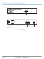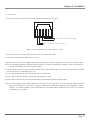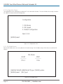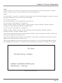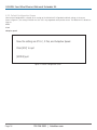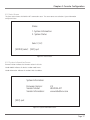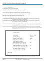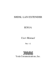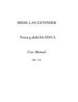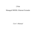
1
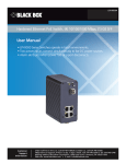
LR0202A-KIT G.SHDSL Four-Wire Ethernet Network Extender Kit Extend Ethernet with full-duplex transmission BOX up to 10.8 Mbps over two pairsBLACK of copper. ® Complies with ITU-T Rec. G.991.2 G.shdsl.bis standards. Reaches distances up to 22,500 feet over 26 AWG twisted-pair cable. Rate adaptive from 192 kbps to 4.608 Mbps on one pair or 384 kbps to 9.216 Mbps on two pairs. Has two RJ-45 connectors for 10BASE-T/100BASE-TX Ethernet ports for combining two separate Ethernet data streams over the same G.SHDSL link. Includes console port for network management configuration. Customer Support Information Order toll-free in the U.S.: Call 877-877-BBOX (outside U.S. call 724-746-5500) • FREE technical support 24 hours a day, 7 days a week: Call 724-746-5500 or fax 724-746-0746 • Mailing address: Black Box Corporation, 1000 Park Drive, Lawrence, PA 15055-1018 • Web site: www.blackbox.com • E-mail: [email protected] •¶ G.SHDSL Four-Wire Ethernet Network Extender Kit Trademarks Used in this Manual Black Box and the Double Diamond logo are registered trademarks of BB Technologies, Inc. Any other trademarks mentioned in this manual are acknowledged to be the property of the trademark owners. We‘re here to help! If you have any questions about your application or our products, contact Black Box Tech Support at 724-746-5500 or go to blackbox.com and click on “Talk to Black Box.” You’ll be live with one of our technical experts in less than 30 seconds. Page 2 724-746-5500 | blackbox.com FCC and IC RFI Statements Federal Communications Commission and Industry Canada Radio Frequency Interference Statements This equipment generates, uses, and can radiate radio-frequency energy, and if not installed and used properly, that is, in strict accordance with the manufacturer’s instructions, may cause interference to radio communication. It has been tested and found to comply with the limits for a Class A computing device in accordance with the specifications in Subpart J of Part 15 of FCC rules, which are designed to provide reasonable protection against such interference when the equipment is operated in a commercial environment. Operation of this equipment in a residential area is likely to cause interference, in which case the user at his own expense will be required to take whatever measures may be necessary to correct the interference. Changes or modifications not expressly approved by the party responsible for compliance could void the user’s authority to operate the equipment. This digital apparatus does not exceed the Class A limits for radio noise emission from digital apparatus set out in the Radio Interference Regulation of Industry Canada. Le présent appareil numérique n’émet pas de bruits radioélectriques dépassant les limites applicables aux appareils numériques de la classe A prescrites dans le Règlement sur le brouillage radioélectrique publié par Industrie Canada. Page 3 G.SHDSL Four-Wire Ethernet Network Extender Kit Normas Oficiales Mexicanas (NOM) Electrical Safety Statement INSTRUCCIONES DE SEGURIDAD 1. Todas las instrucciones de seguridad y operación deberán ser leídas antes de que el aparato eléctrico sea operado. 2. Las instrucciones de seguridad y operación deberán ser guardadas para referencia futura. 3. Todas las advertencias en el aparato eléctrico y en sus instrucciones de operación deben ser respetadas. 4. Todas las instrucciones de operación y uso deben ser seguidas. 5. El aparato eléctrico no deberá ser usado cerca del agua—por ejemplo, cerca de la tina de baño, lavabo, sótano mojado o cerca de una alberca, etc.. 6. El aparato eléctrico debe ser usado únicamente con carritos o pedestales que sean recomendados por el fabricante. 7. El aparato eléctrico debe ser montado a la pared o al techo sólo como sea recomendado por el fabricante. 8. Servicio—El usuario no debe intentar dar servicio al equipo eléctrico más allá a lo descrito en las instrucciones de operación. Todo otro servicio deberá ser referido a personal de servicio calificado. 9. El aparato eléctrico debe ser situado de tal manera que su posición no interfiera su uso. La colocación del aparato eléctrico sobre una cama, sofá, alfombra o superficie similar puede bloquea la ventilación, no se debe colocar en libreros o gabinetes que impidan el flujo de aire por los orificios de ventilación. 10. El equipo eléctrico deber ser situado fuera del alcance de fuentes de calor como radiadores, registros de calor, estufas u otros aparatos (incluyendo amplificadores) que producen calor. 11. El aparato eléctrico deberá ser connectado a una fuente de poder sólo del tipo descrito en el instructivo de operación, o como se indique en el aparato. 12. Precaución debe ser tomada de tal manera que la tierra fisica y la polarización del equipo no sea eliminada. 13. Los cables de la fuente de poder deben ser guiados de tal manera que no sean pisados ni pellizcados por objetos colocados sobre o contra ellos, poniendo particular atención a los contactos y receptáculos donde salen del aparato. 14. El equipo eléctrico debe ser limpiado únicamente de acuerdo a las recomendaciones del fabricante. 15. En caso de existir, una antena externa deberá ser localizada lejos de las lineas de energia. 16. El cable de corriente deberá ser desconectado del cuando el equipo no sea usado por un largo periodo de tiempo. 17. Cuidado debe ser tomado de tal manera que objectos liquidos no sean derramados sobre la cubierta u orificios de ventilación. 18. Servicio por personal calificado deberá ser provisto cuando: A: El cable de poder o el contacto ha sido dañado; u B: Objectos han caído o líquido ha sido derramado dentro del aparato; o C: El aparato ha sido expuesto a la lluvia; o D: El aparato parece no operar normalmente o muestra un cambio en su desempeño; o E: El aparato ha sido tirado o su cubierta ha sido dañada. Page 4 724-746-5500 | blackbox.com CE Statement European Community (CE) Electromagnetic Compatibility Directive This equipment has been tested and found to comply with the protection requirements of European Emission Standard EN55022/EN61000-3 and the Generic European Immunity Standard EN55024. EMC: EN55022(2003)/CISPR-2( 2002): Class A IEC61000-4-2 (2001): 4 KV CD, 8 KV AD IEC61000-4-3( 2002): 3 V/m IEC61000-4-4(2001): 1 KV (power line), 0.5 KV (signal line) Page 5 G.SHDSL Four-Wire Ethernet Network Extender Kit 1. Specifications.......................................................................................................................................................................................... 7 2. Overview .............................................................................................................................................................................................. 8 2.1 Introduction.................................................................................................................................................................................... 8 2.2 Features.......................................................................................................................................................................................... 8 2.3 Application...................................................................................................................................................................................... 9 2.4 What’s Included.............................................................................................................................................................................. 9 2.5 LED Descriptions.............................................................................................................................................................................. 9 2.6 Front and Back Panels.....................................................................................................................................................................10 3. Installation.............................................................................................................................................................................................11 4. Console Configuration...........................................................................................................................................................................12 4.1 Main Menu....................................................................................................................................................................................13 4.2 Configuration Screen......................................................................................................................................................................14 4.2.1 DSL Mode Screen.................................................................................................................................................................14 4.2.2 DSL Speed Screen................................................................................................................................................................15 4.2.3 Default Configuration Screen...............................................................................................................................................16 4.3 Status Screen...................................................................................................................................................................................17 4.3.1 System Information Screen...................................................................................................................................................17 4.3.2 System Status Screen............................................................................................................................................................18 Page 6 724-746-5500 | blackbox.com Chapter 1: Specifications 1. Specifications Standards: ITU-T G.991.2 Compliance, TCPAM-16 Level Line Code, IEEE 802.3/IEEE 802.3u, EMI emissions standard, FCC Part 15 Class A, CE Mark Adaptive Data Rate: 1-pair SHDSL mode: 4.608 Mbps to 192 kbps; 2-pair SHDSL mode: 9.216 Mbps to 384 kbps Fixed Data Rate: 1-pair SHDSL mode: 64 kbps to 5.696 Mbps; 2-pair SHDSL mode: 128 kbps to 10.8 Mbps Maximum Distance: Table 2-1. Fixed data rates (1-pair and 2-pair) and maximum distances on 26 AWG twisted-pair cable. Maximum Distance (Feet/Miles) Fixed Data Rate, 1-Pair Fixed Data Rate, 2-Pair 4500 feet (0.9 miles) 5500 feet (1 mile) 9500 feet (1.8 miles) 12,000 feet (2.3 miles) 13,000 feet (2.4 miles) 13,300 feet (2.5 miles) 13,500 feet (2.6 miles) 15,000 feet (2.8 miles) 17,000 feet (3.2 miles) 18,000 feet (3.4 miles) >18,000 feet (3.4 miles) >18,000 feet (3.4 miles) >18,000 feet (3.4 miles) >18,000 feet (3.4 miles) 5.696 Mbps 4.608 Mbps 3.088 Mbps 2.304 Mbps 2.048 Mbps 1.544 Mbps 1.536 Mbps 1.152 Mbps 768 kbps 512 kbps 384 kbps 256 kbps 192 kbps 64 kbps 10.8 Mbps 9.216 Mbps 6.176 Mbps 4.608 Mbps 4.096 Mbps 3.088 Mbps 3.072 Mbps 2.304 Mbps 1.544 Mbps 1.152 Mbps 768 kbps 512 kbps 384 kbps 128 kbps LAN Interface: Autodetects for 10BASE-T/100BASE-TX and half-/full-duplex; Auto MDI/MDI-X Indicators: (8) LEDs: (1) Power, (1) Test, (1) Loop 1, (1) Loop 2, (1) LAN 1, (1) LAN 2, (2) 10/100M Connectors: Each unit: DSL: (1) RJ-48; LAN: (2) RJ-45; RS-232 console: (1) DB9 F Power: Input: 110/220 VAC, 50–60 Hz Temperature Tolerance: Operating: 32 to 122° F (0 to 50° C) Humidity Tolerance: 5 to 95% noncondensing Size: 1.75"H x 10.25"W x 6.37"D (4.45 x 26.04 x 16.18 cm) Weight: 2.2 lb. (1 kg) Page 7 G.SHDSL Four-Wire Ethernet Network Extender Kit 2. Overview 2.1 Introduction The LR0202A-KIT, a G.SHDSL (Single-pair High-bit-rate Digital Subscriber Line) Ethernet Network Extender, provides broadband full-duplex transmission with bandwidth aggregation up to 10.8 Mbps over two pairs of copper line for point-to-point LAN connectivity between two Ethernet networks. This is enough speed to support VoIP, Web hosting, and teleconferencing. The kit includes two extenders. The LR0202A-KIT can be configured into either STU-C for the central (master) side or STU-R for the remote (slave) side. The LR0202A-KIT conforms to the ITU-T Rec. G.991.2, to meet G.shdsl.bis network requirements. It offers a cost-effective symmetrical broadband solution for bandwidth-hungry applications such as LAN-to-LAN connectivity, Internet access, and VoIP applications over two twisted pairs. Over one pair of 26 AWG (0.5 mm) copper twisted-pair wire, the LR0202A-KIT sends data up to 12,000 feet (2.3 miles, about |3.7 km) at 2.304 Mbps and 4500 feet (about 0.8 miles, 1.3 km) at the maximum rate of 10.8 Mbps. It can also reach 5500 feet (1 mile, 1.6 km) at 9.216 Mbps over two pairs of 26 AWG (0.5 mm) copper twisted-pair wire, and go 22,500 feet (about 6.8 km) at 192 kbps. With its rate-adaptive features, the LR0202A-KIT may provide even longer transmission distances. Users can also select a fixed data rate for the copper line ranging from 64 kbps to 5.696 Mbps over one pair or 128 kbps to 10.8 Mbps over two pairs. The LR0202A-KIT provides a console port for the user to configure the settings and to monitor the connection status. Table 2-1 lists the extenders’ low-speed and maximum-speed fixed data rates and adaptive data rates. Table 2-1. Fixed and adaptive data rates. Fixed Data Rate Adaptive Data Rate Low Speed Maximum Speed Low Speed Maximum Speed 64 kbps, 1-pair 5.696 Mbps, 1-pair 192 kbps, 1-pair 4.608 Mbps, 1-pair 128 kbps, 2-pair 10.8 Mbps, 2-pair 384 kbps, 2-pair 9.216 Mbps, 2-pair 2.2 Features • Complies with ITU-T Rec. G.991.2 G.shdsl.bis standard • SHDSL trellis-coded pulse amplitude modulation (TCPAM) line code • Fixed data-rate selection from 10.8 Mbps to 128 kbps for 2-pair SHDSL lines • Adaptive data rate from 4.608 Mbps to 192 kbps for 1-pair SHDSL mode • Adaptive data rate from 9.216 Mbps to 384 kbps for 2-pair SHDSL mode • Maximum transmission distance: 22,500 ft. over 26 AWG twisted pair • Noise margin • 1 dB is guaranteed for fixed rate and adaptive rate modes • STU-R (remote) follows STU-C's (central office) speed for 192 kbps to 2.304 Mbps in 1-pair fixed rate mode • STU-R follows STU-C's speed for 384 kbps to 4.608 Mbps in 2-pair fixed rate mode • RJ-48 connector for SHDSL line connection • Two RJ-45 connectors for 10BASE-T/100BASE-TX Ethernet switch ports are autosensing and autonegotiating • Ethernet Auto MDI/MDI-X for auto Tx/Rx swap so you don’t need a crossover cable • Console port for network management configuration • (8) LED status indicators Page 8 724-746-5500 | blackbox.com Chapter 2: Overview 2.3. Application LR0202A-KIT (CO Site—Master) Ethernet Switch LR0202A-KIT (Remote Site—Slave) LAN Ethernet Switch LAN Internet Figure 2-1. Sample application. 2.4 What’s Included Your package should include the following items. If anything is missing or damaged, please contact Black Box Technical Support at 724-746-5500. • (2) G.SHDSL Four-Wire Ethernet Network Extenders • (2) Power cords • (2) CAT5e Ethernet cables • This user’s manual on CD-ROM 2.5 LED Descriptions Table 2-1. Indicators. LED Color Function POWER Green Lit when power is on. TEST Green Lit when device is in error. Blinks when device is in self-test. LOOP Green Lit shows SHDSL loop is connected successfully. Blinks shows SHDSL connection is in progress. LAN 1/2 Green Lit when Ethernet is connected. Blinks when Ethernet data is transmitted. 10/100M for LAN1, LAN2 Green Lit when Ethernet is connected at 100 Mbps. Off when Ethernet is connected at 10 Mbps. Page 9 G.SHDSL Four-Wire Ethernet Network Extender Kit 2.6 Front and Back Panels LED Indicators RS-232 Console Port Figure 2-2. Front panel. Power Input Power Switch RJ-45 Connectors Figure 2-3. Rear panel. Page 10 724-746-5500 | blackbox.com RJ-48 Connector Chapter 3: Installation 3. Installation 1. Connect the SHDSL line to the DSL RJ-48 connector on the LR0202A-KIT rear panel. Pins 4 and 5 for SHDSL line Loop 1 Pins 1 and 2 for SHDSL line Loop 2 Figure 3-1. RJ-48 connector, Pins 4 and 5 and Pins 1 and 2. 2. Connect the Ethernet interface to the RJ-45 Port with the included CAT5 cable. 3. Connect the included power cord to the AC outlet. CAUTION: Verify that the AC-DC adapter conforms to your country’s AC power requirement and then insert the power plug. NOTE: The Interconnecting cables should be rated for external use and for the application’s voltage, current, anticipated temperature, flammability, and mechanical serviceability. 4. Turn on the power switch. Set one G.SHDSL Four-Wire Ethernet Network Extender as the CO site (master) from the console port and the other as the REMOTE (slave) site. 5. Set the desired data rate for SHDSL connection from the console port. NOTE: Set both G.SHDSL Four-Wire Ethernet Network Extenders the same. 6. Both G.SHDSL Four-Wire Ethernet Network Extenders will automatically connect with each other. NOTE: Turn on the power switch, and the LR0202A-KIT will then run self-test routines. There will be two or more handshaking cycles when adaptive rate is selected. The system will automatically adapt to the maximum rate according to the loop distances. The maximum adaptive rate is 4.608 Mbps for 1-pair mode and 9.216 Mbps for 2-pair mode. The maximum fixed data rate is 10.8 Mbps. Page 11 G.SHDSL Four-Wire Ethernet Network Extender Kit 4. Console Configuration The LR0202A-KIT provides an RS-232C console port for user to monitor the OA&M status through a VT100 terminal. This section covers the operating procedures and settings for all screen selections. Connect the RS-232 cable to the computer’s COM port as shown in Figure 4-1. Set the personal computer to VT100 or VT102 type through HyperTerminal. Press the <ESCAPE> key and the main menu will be shown on the terminal’s screen. The terminal operations can then start. If you press the <ESCAPE> key and the screen of the terminal does not display, the COM port might be set incorrectly. Choose the correct COM port (COM1 or COM2) on the computer, and press the <ESCAPE> key again to make sure that the main menu appears on the terminal screen. NOTE: Set the COM port should be set as 9600 bps, 8 data bits, 1 stop bit, no parity, and no flow control. RS-232 Cable VT100/102 Terminal PC COM Port Baud rate: 9600 Data bits: 8 Stop bits: 1 Parity: no Flow control: none Figure 4-1. Connection for console port with RS-232 terminal. Page 12 724-746-5500 | blackbox.com Chapter 4: Console Configuration 4.1. Main Menu The Main Menu screen enables you to access the LR0202A-KIT unit’s Configuration and Status screens. For details, refer to Figure 4-2. Welcome to G. Shdsl Ethernet Network Extender User Interface Main Menu 1. Configuration 2. Status Select (1-2) [ENTER] select Figure 4-2. Main menu. The main menu’s pull-down tree structure is shown in Figure 4-3. DSL Mode Configuration DSL Speed Default Configuration Main Menu System Information Status System Status Figure 4-3. Pull-down tree structure of the main menu. Page 13 G.SHDSL Four-Wire Ethernet Network Extender Kit 4.2. Configuration Screen The Configuration screen will display the LR0202A-KIT unit’s connection selections. The screen includes three settings selections: DSL Mode, DSL Speed, and Default Configuration. Configuration 1. DSL Mode 2. DSL Speed 3. Default Configuration Select (1-3): [ENTER] select Figure 4-4. Configuration screen. 4.2.1. DSL Mode Screen From the DSL Mode screen, users can update the DSL mode settings. The DSL Mode settings’ initial values are read from DIP switches. DSL Mode CO/RT ----------- STU-C 2P/1P ----------1 Pair [ARROW RIGHT] [ARROW LEFT] type [SPACE] option [ENTER] select [ESC] quit Figure 4-5. DSL Mode screen. Page 14 724-746-5500 | blackbox.com Chapter 4: Console Configuration CO/RT: CO/RT has 2 options: STU-C and STU-R. To establish a successful connection for two G.SHDSL Two-Wire Ethernet Network Extenders, set one unit to STU-C (CO Site) and the other unit to STU-R (Remote Site). 2P/1P: 2P/1P has 2 options: 1 Pair and 2 Pairs. LR0202A-KIT supports both 1-pair and 2-pair SHDSL applications. To establish a successful connection for LR0202A-KIT, set the two units to the same selection. 4.2.2. DSL Speed Screen From the DSL Speed screen, users can configure DSL transmission rates. For 1-pair setting in the DSL Mode menu, the options are: 64 kbps, 128 kbps, 192 kbps, 256 kbps, 384 kbps, 512 kbps, 768 kbps, 1152 kbps, 1536 kbps, 1544 kbps, 2048 kbps, 2304 kbps, 3072 kbps, 4608 kbps, 5696 kbps, and adaptive speed. For 2-pair setting in the DSL Mode menu, the options are: 284 kbps, 512 kbps, 768 kbps, 1152 kbps, 1544 kbps, 2304 kbps, 3072 kbps, 3088 kbps, 4096 kbps, 4608 kbps, 6176 kbps, 9216 kbps, 10.8 Mbps, and adaptive speed. The user must set both extenders to the same speed selection to establish a successful connection for 64 kbps, 128 kbps, 3072 kbps, 4608 kbps, 5696 kbps, and adaptive speed. For the rate speed options between 192 kbps and 2.304 Mbps, the remote (slave) site will follow the CO (master) site’s speed, regardless of the speed selected for the remote site unit. When setting for adaptive rate, two or more activation cycles are necessary. The system will automatically adapt to maximum speed according to the loop distances. The maximum speed is 5.696 Mbps for 1-pair mode and 10.8 Mbps for 2-pair mode. DSL Speed DSL Speed Setting = Adaptive [ARROW UP] [ARROW DOWN] option [ENTER] select [ESC] quit Figure 4-6. DSL Speed screen. Page 15 G.SHDSL Four-Wire Ethernet Network Extender Kit 4.2.3. Default Configuration Screen When Default Configuration is selected, all the settings of the LR0202A-KIT will go back to default settings. In the screen shown in Figure 4-7, the setting is finished. Press the <ESC> key to go back to the previous screen. The LR0202A-KIT’s default settings are: STU-C 2 Pair Adaptive speed Now the setting are STU-C, 2 Pair, and Adaptive Speed. Press [ESC] to quit [ENTER] quit Figure 4-7. Default Configuration screen. Page 16 724-746-5500 | blackbox.com Chapter 4: Console Configuration 4.3. Status Screen The Status screen shows the LR0202A-KIT’s connection status. The screen covers two selections: System Information and System Status. Status 1. System Information 2. System Status Select (1-2): [ENTER] select [ESC] quit Figure 4-8. Status screen. 4.3.1 System Information Screen Firmware Version: Indicates the firmware version in this unit. Vendor Model: Indicates this device’s vendor model name. Vendor Information: Indicates the vendor’s Web site address. System Information Firmware Version: Vendor Model: Vendor Information: 2.5 LR0202A-KIT www.blackbox.com [ESC] quit Figure 4-9. System Information screen. Page 17 G.SHDSL Four-Wire Ethernet Network Extender Kit 4.3.2. System Status Screen DSL mode: Indicates the current DSL mode setting. Speed setting: Indicates the current DSL speed setting. Speed actual (kbps): Indicates the actual DSL speed in kilobits per second. Link status of Pair #1: Indicates the DSL connection status (either up or down) for Pair #1. Link status of Pair #2: Indicates the DSL connection status (either up or down) for Pair #2. Noise margin of Pair #1 (dB): Indicates the noise margin in dB of Pair #1. Noise margin of Pair #2 (dB): Indicates the noise margin in dB of Pair #2. Line attenuation of Pair #1 (dB): Indicates the line attenuation value in dB of Pair #1. The maximum value is 43 dB when the DSL distance is 22,500 ft. on 26 AWG cable. Line attenuation of Pair #2 (dB): Indicates the line attenuation value in dB of pair #2. The maximum value is 43 dB when the DSL distance is 22,500 ft. on 26 AWG cable. Activation state of Pair #1 (dB): Indicated the DSL startup activation state of Pair #1. The value starts from 05 and gradually reaches the final value of 16. The value of 16 is the DSL linkup state value. The general activation state sequence is 05 20 10 12 16. Activation state of Pair #2 (dB): Indicated the DSL startup activation state of Pair #2. The value starts from 05 and gradually reaches the final value of 16. The value of 16 is the DSL linkup state value. The general activation state sequence is 05 20 10 12 16. System Status DSL Mode: Speed Setting: Speed Actual (kbps): Link Status of Pair #1: Link Status of Pair #2: Noise Margin of Pair #1 (dB): Noise Margin of Pair #2 (dB): Line Attenuation of Pair #1 (dB): Line Attenuation of Pair #2 (dB): Activation State of Pair #1: Activation State of Pair #2: STU-C 2 Pair Adaptive 4608 up 08 22 16 [ESC] quit Figure 4-10. System Status screen. This example shows the values for 26 AWG cable. Page 18 724-746-5500 | blackbox.com NOTES 724-746-5500 | blackbox.com Page 19 Black Box Tech Support: FREE! Live. 24/7. Tech support the way it should be. Great tech support is just 30 seconds away at 724-746-5500 or blackbox.com. About Black Box Black Box Network Services is your source for an extensive range of networking and infrastructure products. You’ll find everything from cabinets and racks and power and surge protection products to media converters and Ethernet switches all supported by free, live 24/7 Tech support available in 30 seconds or less. © Copyright 2013. All rights reserved. LR0202A-KIT, version 2 724-746-5500 | blackbox.com