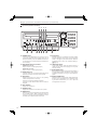
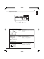
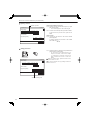
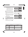
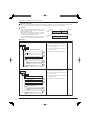
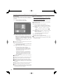
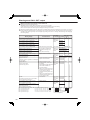
1
ENGLISH
OTHERS
DIGITAL RECORDER
INSTALLERʼS MANUAL
MODEL
DX-TL4516E
DX-TL4516E(Z)
THIS INSTRUCTION MANUAL IS IMPORTANT TO YOU. PLEASE READ IT BEFORE USING YOUR DIGITAL RECORDER.
1
Caution and care
HEAVY OBJECTS SHOULD NEVER BE PLACED ON THE UNIT (E.G., MONITOR)
NEVER TOUCH OR INSERT ANY OBJECT INSIDE THE UNIT
Touching the inside of the cabinet or inserting foreign objects of any kind through the disc loading slot or ventilation holes not
only creates a safety hazard but can also cause extensive damage.
PROTECT THE POWER CORD
Damage to the power cord may cause fire or shock hazard. If the power cord is damaged, turn OFF the MAIN switch and
carefully unplug the cord by holding the main plug.
If this unit is moved with the power on status, the built-in HDD may be damaged. Confirm that more than one minute have
passed since the power cord and the connecting cords were disconnected, then move this unit. Make sure to take the disc out
and close the disc loading slot.
UNPLUG THE POWER CORD DURING A LONG ABSENCE
Turn off the power and unplug the power cord during a long absence.
MAINTAIN GOOD VENTILATION
Do not obstruct the many ventilation holes on the unit. For maximum ventilation, leave some space around the unit and place
the unit on a hard level surface only, and ensure it is not covered during use. Heavy objects should never be placed on the
unit.
WHEN NOT IN USE
When not in use, always eject the disc and turn OFF the MAIN switch.
CABINET CARE
Never use petroleum-based cleaners. Clean with a soft cloth moistened with soap and water and wipe dry.
PVC cables or leads should not be left in contact with the cabinet surface for long periods.
INSTALLATION LOCATION
For excellent performance and lasting reliability install in a location that is:1. Well ventilated, out of direct sunlight and away from direct heat.
2. A solid vibration-free surface.
3. Free from high humidity, excessive dust and away from magnetic fields.
4. Please ensure that the ventilation fan located on the unit’s back panel is not blocked.
UNSUITABLE LOCATIONS
Placing the unit in the following places might shorten the product life:
• Extremely cold places, such as refrigerated warehouses and ice houses
• Places where excessive hydrogen sulfide is likely to be generated, such as hot-springs areas
• Places or locations with salt air environment.
THIS EQUIPMENT DOES NOT PROVIDE CONNECTION FOR USED WITH OUTDOOR OR CABLE DISTRIBUTION
SYSTEMS.
NO OBJECTS FILLED WITH LIQUIDS, SUCH AS VASES, SHALL BE PLACED ON THE APPARATUS.
DO NOT PLACE HEAVY OBJECT ON THIS UNIT.
DO NOT STEP ONTO THIS UNIT.
DO NOT PLACE ANY OBJECTS IN FRONT OF THE DISC LOADING SLOT.
The unit may drop or fall by losing its balance. It may cause injury or failure of the unit.
WARNING:
TO PREVENT FIRE OR SHOCK HAZARD, DO NOT EXPOSE THIS APPARATUS TO RAIN OR MOISTURE.
THIS APPARATUS MUST BE GROUNDED.
MAINS LEAD CONNECTION
The mains lead on this Unit is fitted with a non-rewireable mains plug, incorporating a 5A fuse. If you need to replace
the fuse, use a 5A fuse approved by BSI or ASTA to BS 1362, ensuring you refit the fuse cover. If the mains plug is not
suitable for the sockets in your home, and you require to remove the plug, remove the fuse, cut off the plug then dispose
of the plug immediately, to avoid a possible electric shock hazard. To refit a new plug, follow these instructions; Greenand-yellow: Earth, Blue: Neutral and Brown: Live. As the colours in the mains lead of this Unit may not correspond with the
coloured markings identifying the terminals in your plug, proceed as follows.
• The wire which is coloured green-and-yellow must be connected to the terminal in the plug which is marked by the
letter E or by the safety earth symbol or coloured green or green-and-yellow.
• The wire which is coloured blue must be connected to the terminal which is marked with the letter N or coloured black.
• The wire which is coloured brown must be connected to the terminal which is marked with the letter L or coloured red.
This unit complies with the requirements of the EC Directive 2004/108/EC, “EMC Directive” and 2006/95/EC, “Low Voltage
Directive”. The requirements for the susceptibility according to EN 55024 and the requirements for interference according
to EN 55022 are observed for the operation on residential areas, business, light industrial premises and in small scale
enterprises, inside as well as outside of the building. All places of operation are characterised by their connection to the
public low voltage power supply system. This unit is manufactured in accordance with EN 60950-1.
2
ENGLISH
Note: This symbol mark is for EU countries only.
This symbol mark is according to the directive 2002/96/EC Article 10 Information for users and Annex IV.
Your MITSUBISHI ELECTRIC product is designed and manufactured with high quality materials and components which
can be recycled and reused.
This symbol means that electrical and electronic equipment, at their end-of-life, should be disposed of separately from
your household waste.
Please, dispose of this equipment at your local community waste collection/recycling centre.
In the European Union there are separate collection systems for used electrical and electronic product.
Please, help us to conserve the environment we live in!
Notice about construction of the surveillance system using this unit
• This unit can be controlled by the external devices via RS-232C terminal or LAN terminal. This unit can also be used to
control external devices via external terminal, RS-422/485 terminal, or RS-232C terminal. Owning to these functions,
this unit flexibly applies to the high grade security system, but the whole surveillance system may be affected by the
malfunction of this unit or the external devices depending on the setting contents of this unit, the connection with the
external devices, or combination between this unit and the external devices.
• When configuring a surveillance system using this unit, it is recommended to confirm first that this unit operates
normally with the other devices connected.
• It is recommended to copy or back up the important recorded contents.
• Damages rising out of any operational error of the surveillance system or loss of the recorded data or any other
damages because of any user malfunction of this unit are not covered.
• Do not use the notification function of this unit for making critical judgement nor any purpose related to human lives.
• When this unit cannot recognize the external device which is being used for recording due to the power failure,
decreased voltage, or other failures, the recording point may be moved to the internal HDD of this unit or the other
external HDD. To prevent occurrence of such problem, it is recommended to use uninterruptible power supply.
• If the power plug is disconnected or the breaker switch is turned off during recording, HDD may be damaged or
playback of recorded data may become impossible.
If the breaker switch is turned on and off everyday, set the timer recording to be performed only for the period that the
breaker is on and do not turn off the breaker during recording.
There may be cases when the unit's built-in motion detection function does not operate properly due to external
condition, video input signal, or other factors.
The user will not be indemnified for problems (e.g., recording failure or playback failure) that occur with either the unit or
a connected device during operation. It is recommended to back up the important recordings regularly as a precaution
against possible breakdowns and accidents.
Recordable time and product warranty
Continuous recordable time and the estimated time displayed on the menu screen indicate the continuous time of
recording operation of this unit. They indicate the period neither for product warranty nor that for reliability of used parts.
•
•
•
•
This unit uses a built-in HDD, which is a precision device. Handle this unit with sufficient care.
Do not subject this unit to vibrations or shocks. This may cause trouble specially when the power of the unit is turned
on or when the HDD is being accessed, and sufficient care is required.
Do not disconnect the power plug while the power of the unit is turned on or while recording or playing.
For early detection of faults, we recommend that you request inspection once a year.
The HDD and cooling fan of this unit are driving parts. For stable recording, it is recommended that both of these parts are
replaced every 30,000 hours.
(This interval is for reference purpose only and does not indicate the warranty period of the parts.)
Beginning
3
Caution and care (continued)
DISCLAIMER
In any event, Mitsubishi assumes no responsibility or reliability for the following:
1. Disassembly, repair, or alteration of this unit by user or installer.
2. Failure or breakdown in or damage to this unit resulting from misuse or careless handling by user or installer.
3. Inconvenience or damages arising out of inability to display or record pictures due to any reason or cause other than
breakdown or failure in this unit.
4. Failure in this unit due to combination with other equipment manufactured by a third party or inconvenience or
damages resulting from such failure.
5. Inconvenience, damages, or claims arising out of breakdown in this unit or loss of recorded video data due to
replacement of the built-in HDD by user or installer.
6. Inconvenience or damages arising out of breakdown in this unit or inability to display or record pictures due to natural
disaster including earthquake and storm.
7. Inconvenience, damages, or claims arising out of breakdown in this unit or loss of recorded video data due to impact
or vibration to the built-in HDD or an environmental factor such as temperature at the installation site.
8. Demand for damages or other claim of infringement of privacy if the pictures monitored or recorded by user become
public or are used for any purpose other than surveillance for whatever reason.
INSTALLATION LOCATION AND HANDLING
• Place this unit horizontally and in a stable place. If this unit is not placed correctly and used in an unstable place, the unit
may be damaged such as removal of the DVD/CD disc.
• Do not place this unit close to other electronic or magnetic equipment. This will avoid video and audio distortion.
• When a monitor and this unit are placed vertically, the pictures may be distorted or DVD/CD disc may not be ejected.
• Do not let stick your hands into the disc loading slot. You may get your hand caught in the slot and may got injured. If you
get your hand caught, do not get out of the slot by force. Contact your dealer after turning off the power and disconnecting
the plug.
DVD/CD DISC
• Do not use the disc cracked, deformed or repaired with adhesive. The disc may fly into pieces and cause injury.
• Do not touch the playback surface when holding the disc.
• When dew condensation occurs on the disc, wipe the surface off before use.
• Dirt such as fingerprints or dust causes the deterioration of the picture quality and audio quality. Gently wipe the DVD/CD
disc from the center to the outside with a soft cloth.
• When the disc is very dirty, soak a soft cloth with water and screw water of it, wipe off the dirt lightly, then wipe with a dry
cloth.
• Do not use solvent such as benzine and thinner, a record cleaner, and static-stopper. They may damage the disc.
• Do not use the disc described below. They may damage the disc itself or this unit.
Discs on which a piece of paper or sticker is put, or a disc damaged.
Discs which the label is peeled or a disc with oozing.
Discs cracked, deformed, or repaired with adhesive.
• Store the disc in the specified casing, avoiding the following places.
Places where it will be subjected to direct sunlight.
Places with excessive dust.
Places where it will be subjected to high temperatures or high humidity.
• DVD movie (cinema) or personal recorded picture cannot be played back on this unit. Only the pictures recorded on this
unit can be played back.
• Do not use the disc which has been used on the personal computer, failed to be copied, or stopped during copying due to
the power failure because they may cause malfunction of the unit.
• Although you can copy the data on DVD/CD with this unit and playback that data on the personal computer using the
supplied application software, not all the personal computers or DVD/CD drives are ensured for proper playback of such
data.
MAINTENANCE OF THE LENS FOR RECORDING/PLAYBACK (LASER PICKUP)
• When any dust adheres on the lens for recording/playback, the picture may be distorted or the audio may skip. Also normal
recording or playback may not work. Ask your dealer how to correct this problem.
Be careful, do not use the commercial lens cleaning disc, they may damage the lens.
PRECAUTION CONCERNING EXTERNAL DEVICE
• The various external HDDs can be connected to this unit in order to expand the memory or to use as the copy device.
However, during recording or playing back a picture at high rate, some pictures may be missed due to the slow rate of data
transfer or the slow speed of response from the external device connected. Be sure to check the operation sufficiently in
advance.
• Do not use the power control function of the external device which uses bus power of this unit.
• The external device to be used may be unsuitable for the operation you want to set. It is recommended to consult your
dealer when using the external device.
Warning
This is a class A product. In a domestic environment this product may cause radio interference in which case the user may
be required to take adequate measures.
CLASS 1 LASER PRODUCT
4
Note
ENGLISH
Thank you for purchasing Mitsubishi digital recorder DX-TL4516E/DX-TL4516E(Z) (hereinafter referred to as “Product”).
Before using this Product, please be sure to read the Software License Agreement on page 7 of the user's manual with
regard to the software contained in this Product (hereinafter referred to as “Licensed Software”). By using this Product,
you are agreeing to be bound by the terms and conditions of the following Software License Agreement.
This Product contains software programs that are covered by GNU General Public License or GNU Lesser General Public
License. Such software programs are excluded from Licensed Software and not covered by the following Software License
Agreement. For the terms and conditions for use of the software programs covered by GNU General Public License or GNU
Lesser General Public License, please see “Notice about software to which GNU GPL/LGPL is applied”*.
In addition, this Product contains “Apache” and “OpenSSL (including “Original SSLeay” library).” These software programs
are also excluded from Licensed Software and not covered by the following Software License Agreement. For the terms and
conditions for use of these software programs, please see “Notice about Apache software”* and “Notice about OpenSSL
software”*.
Each of “Berkeley Database,” “agetty,” “expat,” and “zlib” contained in this Product is other open source software. These
software programs are excluded from Licensed Software and not covered by the following Software License Agreement. For
the terms and conditions for use of these software programs, please see “Notice about other open source software”*.
*
The documents of “Notice about software to which GNU GPL/LGPL is applied,” “Notice about Apache software,” “Notice
about OpenSSL software,” and “Notice about other open source software” are contained (in the format of electronic
files as notice_GPL_LGPL_ja.pdf, notice_Apache_ja.pdf, notice_OpenSSL_ja.pdf, and notice_other_ja.pdf) in the
“OpenSoft_License” folder in the CD supplied with this Product.
Beginning
5
Features
DX-TL4516E/DX-TL4516E(Z) is a digital recorder that is equipped with HDD as its main memory and 16ch triplex multiplexer.
Addition to these features, this system has a very sophisticated video signal and data processing technique that provides
high quality picture, stable operation and reliability. The graphical user interface and pointing devices make the operation very
easy and comfortable in live monitoring and also in the handling of data from recording to export. The system offers excellent
performance and has features to suit many video surveillance applications.
Refresh rates of 800pps*/system
Thanks to the newly developed multiplexing circuit, every camera can be viewed at 50 pps refresh rate in all screen formats.
pps* : picture per second
Triplex
User can view live and playback pictures on the same monitor in all screen multi-split layouts without disrupting recording.
Dual Multiplexer Outputs
The DX-TL4516E/DX-TL4516E(Z) has two video outputs (Output A / B), and both of the outputs can show single-screen, 4, 9,
10, 13 and 16 split-screen, Switched Cameras, Alarmed Camera in live mode and Recorded pictures. On Screen Menu are
shown only on monitor Output A. It is also possible to view playback pictures of different cameras at the same time with these
two video outputs.
Covert Camera Function
It is possible to hide pictures of selected cameras that are installed in sensitive areas and should only be viewed by authorized
personnel. It can be switched by <Multiplexer Setting>.
GUI
MENU, GUI (Graphical User Interface), guides the operators to their desired menu pages quickly. If the users need additional
information on MENU functions, just press the HELP key and instructions will appear on screen. The menu supports English,
German, French, Spanish, Italian, and Russian. Function keys on the front panel or USB mouse can operate the menu on the
DX-TL4516E/DX-TL4516E(Z).
Recording rate up to 100 pps/system
Because of the new recording circuit and compression chip, the maximum recording speed is 100 pps in total, this means that
the system can record pictures with speed of up to 6.25 pps on all 16 channels. With this speed recorded pictures are seen by
the eye as real-time.
JPEG2000
The system uses JPEG2000 compression. JPEG2000 is the standard and ideal compression method for still pictures.
Because pictures are compressed to a user defined file size one by one, the estimated recording time calculated by the
system automatically is very accurate. Special playback search functions and transmission over network also benefit from this
compression method. File sizes for each picture quality are minimized to improve storage efficiency over previous models.
Individual Recording Setting
Recording speed and picture quality (picture file size) can be set for each camera individually, it is also possible to set alarm
recording setting in addition to normal recording setting. By adjusting the recording speed and picture quality, it is possible to
use HDD storage space efficiently.
Audio Recording
Audio input is featured. The audio such as cash register operation and conversation with customers can be recorded clearly
together with the monitoring pictures.
Copy
User can make a copy of recorded picture data by using built in CD/DVD Drive on the DX-TL4516E/DX-TL4516E(Z). Or, also
you can copy the data to other digital media such as HDD and USB Memory through Serial Bus Interface.
6
ENGLISH
Microsoft is either registered trademarks or trademarks of Microsoft Corporation in the United States and/or other countries.
All other company and product names appearing herein are the property of their respective owners.
Beginning
7
Contents
Caution and care ............................................................ 2
Note.................................................................................. 5
Features .......................................................................... 6
Contents .......................................................................... 8
Flowchart....................................................................... 10
Flowchart for connection and settings .......................... 10
Major operations and their functions ......................... 12
Front view ..................................................................... 12
Front view (inside of the door) ...................................... 14
Loading/Ejecting a DVD or CD ..................................... 15
Rear view ...................................................................... 16
Connections .................................................................. 18
Connecting to CCTV camera, monitor, and sensor ...... 18
Alarm recording connection .......................................... 19
Clamping the cables ..................................................... 20
Connecting to an analogue video cassette recorder .... 20
Optional items ............................................................... 21
Recommended items .................................................... 21
Precaution concerning connection with HDD extension
unit ................................................................................ 21
How to set the menus .................................................. 22
Setting the menus ......................................................... 22
Setting the menu using a mouse ............................ 22
Setting the menu using the front panel buttons ...... 22
Displaying a menu screen....................................... 23
Closing a menu screen ........................................... 23
Selecting an item .................................................... 23
Inputting numbers ................................................... 24
Setting parameters.................................................. 24
Symbols in the menus .................................................. 25
Setup Wizard ................................................................. 26
Setup Wizard ................................................................ 26
Menu chart .................................................................... 28
Menu chart .................................................................... 28
User Menu .............................................................. 28
Setup Menu............................................................. 30
System Menu .......................................................... 37
User Menu
Search ........................................................................... 39
Selecting the search function........................................ 39
Select Source Device ................................................... 39
Search by Time and Date ............................................. 39
Search by Alarm List ..................................................... 39
Find data storage location ............................................ 39
Search by Book Mark ................................................... 39
Search by Motion .......................................................... 40
Copy............................................................................... 41
Copy Data to Copy 1 Drive/Set Copy 1 Drive ............... 41
Copy Data to Copy 2 Drive/Set Copy 2 Drive ............... 42
Copying the data of this unit to a video cassette .......... 43
Playback software......................................................... 44
Information .................................................................... 46
Information .................................................................... 46
Protect Data .................................................................. 47
Protect Data .................................................................. 47
PTZ Control ................................................................... 48
PTZ control using the menu.......................................... 48
PTZ control using the front panel buttons ..................... 48
8
Setup Menu
Recording ...................................................................... 49
Settings concerning normal recording and
alarm recording ............................................................. 49
Pre-alarm recording ................................................ 49
Set Recording Pattern A (Normal/Timer) to D (Timer) .. 49
Alarm Input.............................................................. 51
Emergency Recording Setup ........................................ 52
Emergency recording .............................................. 52
Long pre-alarm recording........................................ 53
Audio Recording Setup ................................................. 53
Timer .............................................................................. 54
Timer ............................................................................. 54
Overlapped timer settings ....................................... 55
Motion Det ..................................................................... 56
Set Motion Detection Pattern A/Set Motion Detection
Pattern B ....................................................................... 56
System ........................................................................... 58
Time/Date Setting ......................................................... 58
Menu Language Selection ............................................ 58
Rear Terminal Setting ................................................... 58
Mode Out Settings .................................................. 58
Call Out Settings ..................................................... 59
Key Sound .............................................................. 59
Buzzer ..................................................................... 59
Password Setting .......................................................... 60
SIMPLE LOCK ........................................................ 60
Activating the simple lock .................................. 60
Releasing the simple lock .................................. 60
PASSWORD LOCK ................................................ 60
Using “Operation control” of PASSWORD LOCK
(level 1 to 3) ....................................................... 60
Registering the PASSWORD .................................. 60
Activating the PASSWORD LOCK .......................... 61
Releasing the PASSWORD LOCK ......................... 61
Changing the PASSWORD ..................................... 61
Changing the lock mode from PASSWORD LOCK
to SIMPLE LOCK .................................................... 61
Multiplexer function related button operations/
operation table .............................................................. 62
Camera number button operations ......................... 62
SPLIT buttons operations ....................................... 62
SEQUENCE button operations ............................... 62
DIGITAL ZOOM button operations .......................... 62
The function of the SPLIT, SEQUENCE, DIGITAL
ZOOM, and camera number buttons ...................... 63
Multiplexer Setting ........................................................ 64
Output A Settings .................................................... 64
Output B Settings .................................................... 65
Alarm Display Setting.............................................. 66
Covert Camera Setting ........................................... 66
On Screen Display Setting............................................ 67
On Screen Information ............................................ 67
Camera Title............................................................ 67
Recorder Title.......................................................... 68
Monitor Output Adjust ............................................. 68
Reset to Factory Setting ............................................... 68
Menu Data ..................................................................... 69
Load Menu Data ........................................................... 69
Save Menu Data ........................................................... 69
COM/LAN ....................................................................... 70
RS-232C Setting ........................................................... 70
RS-485 Setting ............................................................. 70
LAN (Communication) Setting ...................................... 71
PTZ Setting.................................................................... 72
PTZ Camera Configuration ........................................... 72
Configuration Check List............................................... 72
Service Info ................................................................... 73
System Log List ............................................................ 73
Elapsed Operating Time ............................................... 73
Disk Information ............................................................ 73
Restore .......................................................................... 74
Restore Data to Main HDD from Drive 1/2/
Export Drive 1/2 Configuration...................................... 74
Memory .......................................................................... 75
Add/Remove HDD Device ............................................ 75
Notes for using the external device......................... 76
Attaching the HDD and setting the ID number ........ 76
The order of recording/playback when internal and
external HDDs are registered as the main device .. 76
Add/Remove DVD/CD Drive ......................................... 76
Data Management Setting for Main Memory ................ 77
Recording Data Readout Setting .................................. 78
Data Clear ...................................................................... 79
Main Storage Memory .................................................. 79
Copy 1/Copy 2 .............................................................. 79
Other convenient functions ......................................... 80
Various playback functions ........................................... 80
Playing still frames .................................................. 80
Shuttle viewing/direct shuttle viewing ..................... 80
Shuttle hold ............................................................. 80
Frame-by-frame playback ....................................... 80
Reverse playback ................................................... 80
High-speed fast-forward/high-speed rewind ........... 80
Changing playback intervals ................................... 81
Simultaneous playback during recording ................ 81
Playback the latest recorded contents .................... 81
Triplex playback ...................................................... 81
Registering the picture .................................................. 82
Registering a bookmark .......................................... 82
Picture copy ............................................................ 82
Functions of the unit in case of power failure ............... 83
Power failure compensation circuit ......................... 83
Power failure reset recording .................................. 83
Log function when power failure occurs while the unit
is in operation or the MAIN switch on the rear of the
unit is turned OFF ................................................... 83
RESET button ............................................................... 83
Operation examples ..................................................... 84
Operation example 1 .................................................... 84
Operation example 2 .................................................... 85
Operation example 3 .................................................... 86
Operation example 4 .................................................... 88
Basic operations .......................................................... 90
Basic multiplexer functions ........................................... 90
Multiplexer buttons .................................................. 90
Basic manual recording ................................................ 91
Setting the recording rate and picture grade for normal
recording ................................................................. 91
Basic playback .............................................................. 92
Basic search ................................................................. 93
Search by Time and Date ....................................... 93
Search by Alarm List ............................................... 94
Communications by Web Browser ............................. 95
Communications by Web Browser................................ 95
The personal computer product requirements ........ 95
Connections ............................................................ 95
Login ............................................................................. 95
Main Menu .................................................................... 96
Live Monitoring........................................................ 97
Playback ................................................................. 98
Time Search ...................................................... 98
Alarm List Search .............................................. 99
Image Search .................................................... 99
Configuration Menu................................................. 99
User Registration ............................................. 100
Recorder Title & Camera Titles ....................... 101
E-mail Setup .................................................... 102
Access Mode Setup ........................................ 103
Clock Setup ..................................................... 103
Logout ................................................................... 104
Change Login User ............................................... 104
ENGLISH
System Menu
Recording time table .................................................. 105
Continuous recording time table ................................. 105
Troubleshooting ......................................................... 106
Warnings and CALL OUT output............................... 108
Warnings and their appropriate countermeasures ...... 108
Check sheet .................................................................110
Glossary ...................................................................... 126
Glossary...................................................................... 126
Relation of recording operation to the number of
cameras and recording rate settings .......................... 126
Specifications ............................................................. 127
How to read this manual
Viewing displays
(Refer to this information when operating):
Reference information concerning operation
(Caution required):
Cautionary items concerning operation
(See reference page):
Reference item and page number
Finding desired information
There is a “Contents” at the beginning of this manual. In
addition, reference pages are indicated throughout this
manual.
Troubleshooting
Read Troubleshooting (pages 106,107) for possible
remedies to the problem.
Menu settings
See Check list (pages 110-125) for available setting
parameters for each menu.
Beginning
9
Flowchart
Flowchart for connection and settings
This is a flowchart of connection and settings for making an alarm recording with timer recording and then search, playback,
and copy the recorded data.
Connections
• Connections for camera, monitor, and sensor.
See “ Connecting to CCTV camera, monitor,
and sensor” on page 18.
• Connection for the alarm recording.
See “ Alarm recording connection” on page
19 and “ Rear view” on page 16.
Connections
• Connections for camera, monitor, and sensor.
See “ Connecting to CCTV camera, monitor,
and sensor” on page 18.
• Connection for the alarm recording.
See “ Alarm recording connection” on page
19 and “ Rear view” on page 16.
Boot-up the unit
Boot-up the unit
When not executing Setup Wizard:
See “ Setup Wizard” on page 26.
Only when the unit is turned on for the first time, the
<Setup Wizard> screen is displayed automatically. It
is not displayed next time.
When executing Setup Wizard:
See “ Setup Wizard” on page 26.
Only when the unit is turned on for the first time, the
<Setup Wizard> screen is displayed automatically. It
is not displayed next time.
• Set the present time and HDD settings in each menu
manually. (“ Time/Date Setting” on page 58. Set
the present time. “ Data Management Setting for
Main Memory” on page 77. Set the alarm area.)
• The language, present time, HDD configuration, and
recording settings are set automatically by following
the instructions in the menu.
Recording
Making the initial menu settings
• Setting the present time display mode.
See “ On Screen Information” on page 67.
• Setting the audio recording.
See “ Audio Recording Setup” on page 53
and “ Continuous recording time table” on page
105.
Making the HDD settings
• Setting the repeat recording.
See “ Data Management Setting for Main
Memory” on page 77.
• Setting the remaining HDD capacity.
See “Low Memory Alarm Setting” on page 58
• Setting the CALL OUT.
See “ Call Out Settings” on page 59.
• Setting the buzzer.
See “ Buzzer” on page 59.
Making the multiplexer settings
• Making the split screen settings.
See “ Multiplexer Setting” on page 64.
• Making the sequence setting.
See “ Multiplexer Setting” on page 64.
10
Setting the motion detection
• Selecting the camera number.
• Setting the detection areas.
• Setting the sensitivity.
• Setting the minimum number of dots for starting
the motion detection operation.
• Setting the detection interval.
See “Motion Det” on page 56.
Setting the timer recording
• Setting the normal/alarm recording or pre-alarm
recording.
• Setting the recording rate/picture grade for
normal recording.
• Setting the recording rate/picture grade for alarm
recording.
• Setting the motion detection recording.
• Selecting the camera selection during the alarm
recording and trigger for alarm recording.
• Setting the alarm recording time.
• Setting the pre-alarm recording time.
• Setting the PTZ camera preset.
See “ Set Recording Pattern A
(Normal/Timer) to D (Timer)” on page 49.
• Setting the timer program.
• Setting the holiday.
• Selecting the timer program number.
• Making the timer recording settings.
• Selecting the day of the week.
• Selecting the start time.
• Selecting the end time.
• Selecting the program mode.
• Selecting the motion detection mode.
(• Selecting the special day of the week.)
See “Timer” on page 54.
The search is completed and the search result is
displayed
ENGLISH
Setting other various functions
• Setting the camera title/recorder title.
See “ Camera Title” and “ Recorder Title”
on pages 67, 68.
• Setting the display mode.
See “ On Screen Information” on page 67.
• Setting the output signal of the unit status.
See “ Mode Out Settings” on page 58.
Playback the search result
• Selecting the camera number to be played back.
See “ Multiplexer Setting” on page 64.
• Selecting the split/sequence screen.
See “ Multiplexer Setting” on page 64.
• Playback the recorded data.
See “ Basic playback” on page 92.
• Selecting the playback speed.
See “ Various playback functions” on page
80.
Copy the data
• Setting the copy device.
See “ Add/Remove HDD Device” or “ Add/
Remove DVD/CD Drive” on pages 75, 76.
• Setting the copy function.
See “ Copy Data to Copy 1 Drive” or “
Copy Data to Copy 2 Drive” on pages 41, 42.
Timer recording is executed and completed
See “ Warnings and their appropriate
countermeasures” on page 108.
Searching the recorded data
• Setting the device to be searched.
See “ Select Source Device” on page 39.
• Setting the alarm list search.
See “ Search by Alarm List” on page 94.
Beginning
11
Major operations and their functions
Front view
17
1
1.
2
3
18
4 5
6 7 8 9 10 11
POWER indicator
Illuminates when the unit is ON (MAIN switch on the
rear is ON and the POWER button in the front has been
pressed.) Turns off when the unit is in stand by mode
(only rear switch is ON) or MAIN switch on the rear is
turned off. It takes about 1 or 2 minutes from pressing
the POWER button to switch the unit ON. When the unit
is in operational transition such as boot-up, the indicator
flashes and other operations are not accepted.
2.
REMOTE jack
Input connector for optional wired remote controller.
3.
ACCESS indicator
Illuminates during accessing to internal HDD or
peripheral recording devices. Press the POWER button
after the ACCESS indicator is turned off and “POWER
OFF” is displayed on the LCD display.
4.
COM (COMMUNICATION) indicator
Illuminates when establishing the communication with
personal computer.
5.
ALARM indicator
Illuminates during alarm recording.
6.
7.
TIMER indicator
13 1415 16
PRE ALARM indicator
Illuminates during pre-alarm recording.
It also illuminates when pre-alarm recording has been
set.
10. COPY 1 indicator
Illuminates while performing copy 1 operation.
Flashes when starting or ending the copy 1 operation.
11. COPY 2 indicator
Illuminates while performing copy 2 operation.
Flashes when starting or ending the copy 2 operation.
12. REC/STOP button
Starts recording. The button lights up during recording.
When pressing the button for more than 2 seconds, the
recording stops and the light turns off.
When pressing this button for more than 2 seconds during alarm recording, recording stops.
During timer recording, recording does not stop even if
the button is pressed.
13. SPLIT screen buttons (
, , , ,
)
Selects split screen to be displayed.
Used for the menu settings.
14. SEQUENCE button
Used to select and display the sequential screens.
LOCK indicator
When pressing the button during PTZ mode, the angle
of the camera adjusts in the upward direction.
M-DET indicator
Illuminates when the motion detection function is activated.
Flashes during motion detection recording.
12
12
21
20
Illuminates during timer recording or timer recording
stand-by mode.
Illuminates while simple lock or password lock is turned
on.
8.
9.
19
TILT
button
Switches this unit to PTZ mode to control the PTZ camera connected.
Camera control buttons
The following buttons control PTZ motion during PTZ
mode. This unit must be in single screen display.
CAMERA ZOOM button
Adjusts the camera zoom. Press this button and then
turn JOG to the left (wide) or right (tele) to adjust the
camera zoom.
21. Camera number buttons (1 to 16)
Displays the picture supplied from the camera connected. The number of the button corresponds to that of the
CAMERA IN connector on the rear panel. The button of
the displayed camera number lights up.
Used for the preset function of the PTZ camera control.
Used for the menu settings.
ENGLISH
15. PTZ (Pan, tilt, and zoom) button
M-DET DOT ON/OFF/M-DET AREA SET UP
(camera number 9 and 13)
Used for setting the detection area of the motion detection function.
FOCUS button
Adjusts the focus of a camera. Press this button and
then turn JOG to the left (far) or right (near) to adjust the
focus.
IRIS button
Adjusts the iris of a camera. Press this button and then
turn JOG to the left (close) or right (open) to adjust the
iris.
PRESET button
Presets up to 16 viewing positions. Press this button and
then press the camera number button within 3 seconds
to preset the points.
AUTO PAN button
Activates auto pan of the camera connected.
16. OUTPUT A/B button
Switches the multiplexer output between A and B. The
light turns off when OUTPUT A is selected and on when
OUTPUT B is selected. It affects both, playback and
search functions. The menu cannot be displayed when
this button is illuminated.
TILT
button
When pressing the button during PTZ mode, the angle
of the camera adjusts to the downward direction.
17. Disc loading slot
Accepts DVD disc or CD to copy/back up.
The supported discs are:
DVD-RW, DVD-R, CD-R, and CD-RW
OPEN/CLOSE
button
Opens or closes the disc loading slot.
BUSY indicator
Flashes or illuminates during recording or playback.
18. LCD display
Displays the present time and the status of the unit.
19. SHUTTLE ring
Adjusts the playback speed, and rewinds or forwards the
recorded pictures.
Pans the camera.
20. JOG dial
Forwards or rewinds the picture during playback (frameby-frame).
Uses for controlling PTZ cameras connected.
Beginning
13
Major operations and their functions (continued)
Front view (inside of the door)
25 26 27 28
22
23
24
29 30 31 32
22. POWER button
Turns on the unit (MAIN switch on the rear of this unit
must be ON). When the button is pressed again, the unit
switches to stand-by mode. The POWER and other button operations are not accepted while the POWER indicator is flashing.
23. ANALOGUE OUTPUT connectors
VIDEO OUT connector
Output connector for video signal (RCA pin).
AUDIO OUT connector
Output connector for audio signal (RCA pin).
24. SERIAL BUS port
Input and output port for the devices equipped with SERIAL BUS connectors. Bus power cannot be used.
25. HELP button
Displays the help menu (for caution on use, operating
method, and explanation on functions).
Used when the warning message is displayed.
This button can be used even while the menu screen is
displayed.
26. SET UP button
Displays the <User Menu>.
27. SEARCH button
Displays the <User Menu> with search menu opened.
28. TIMER button
Sets the unit to timer recording/stand-by mode and lights
up the TIMER indicator. When pressing this button for
more than 2 seconds, timer recording/stand-by mode is
cancelled and the TIMER indicator is turned off.
14
33
29. LOCK button
Activates simple lock or password lock when pressing
while the MAIN switch (main power) on the rear panel is
turned on and lights up the LOCK indicator. Moreover,
the password can be set on the <Password Setting> (
page 60).
30. TRIPLEX PB button
In split screen display, inserts the playback picture of
needed camera while also displaying the live picture
from other camera.
31. BOOK MARK button
When pressing this button during frame still playback of
the single screen display, the selection screen appears
to register the bookmark or to copy the picture being displayed.
32. DIGITAL ZOOM button
Pressing this button in single screen display displays the
screen in 100 % magnification (live or playback). Pressing the camera number button (11, 14, 15, or 16) moves
the magnification centre point.
STOP button
Stops playback.
PAUSE/JUMP TO END button
Switches the playback to still frame playback when
pressing this button during playback. Resumes playback
when pressing the button again. The button lights up
during still frame playback.
When pressed during shuttle playback, the set playback
speed is maintained even when letting go of the SHUTTLE ring. (Shuttle hold)
When pressed during the unit is in stop mode of playback, the frame still picture around the end point of the
latest recording appears. (Jump to end)
REV. PLAY (REVERSE PLAY) button
Starts reverse playback. The button lights up during reverse playback.
PLAY button
Starts playback. The button lights up during playback.
SPEED (+ and –) button
Switches the playback interval speed during normal or
reverse playback.
Loading/Ejecting a DVD or CD
Before using a disc, read the cautionary notes described
in the manual included with the disc.
step1.
Press the OPEN/CLOSE button.
• The disc loading slot opens.
ENGLISH
33. Operation buttons
[When loading the disc:]
step2-1. Place the disc onto the tray.
• Make sure that the disc is inserted properly with
the label side up.
[When ejecting the disc:]
step2-2. Eject the disc from the tray.
step3.
Press the OPEN/CLOSE button again.
• The disc loading slot closes.
Do not eject the disc while copying/restoring, saving/loading menus, or immediately after inserting the disc. The
disc or the contained data may be damaged.
Use the disc which we recommend. When a disc other
than the recommended is used, the data may not be read
or written correctly. Consult your dealer for recommended
usable discs.
When using DVD-RW or CD-RW disc, initialize the disc
page 79) before using.
by <Data Clear> (
Although you can copy the data on DVD/CD with this unit
and playback that data on the personal computer using
the supplied application software, not all the personal
computers or DVD/CD drives are ensured for proper playback of such data.
Before using the DVD drive, check whether that the drive
supports the medium to be used. It is recommended to
use the DVD-Multi drive when you playback the data on
the personal computer.
Beginning
15
Major operations and their functions (continued)
Rear view
3
1
1.
2
4
5
MAIN switch
This is the main power switch. To use this unit, set this
switch to ON. Otherwise, the front power button does not
turn the unit on/off.
2.
AC power socket
Used to connect the power cord. Earth terminal is used
for safety. Use the 100 to 240 V outlet with ground terminal.
This unit must be earthed at all times. Never connect
this unit to a power outlet which does not have an earth
terminal.
Use the supplied AC power cord.
3.
CAMERA connectors
Do not connect superimposed voltage camera because
it can cause damage to the unit.
CAMERA IN connectors
Input connector for video signal of camera (BNC connector).
CAMERA OUT connectors
Output connector for video signal of camera (BNC connector). If the MAIN switch is turned on, the signal from
CAMERA IN connector is looped out to this connector.
4.
ALARM IN terminals
Input terminals for alarm signal. Alarm signal input is acceptable once a second. However, when multiple signals
are input at the same time, not all the signals may be acceptable.
ALARM OUT terminals
Output terminals for alarm signal. This terminal outputs
signal for about 2 seconds when alarm or motion detection is input to each sensor connected.
16
6
5.
7
8
9
10 11 12 13 14 15
Keyhole for anti-theft lock
Used to connect a commercially available anti-theft cable manufactured by Kensington.
6.
I/O terminals
CLOCK ADJ terminal
Input terminal to set the present time. Time display is
adjusted to the nearest hour (00 minutes 00 seconds)
when this terminal receives the signal.
The on-screen clock is reset to the nearest hour by applying a signal input of the CLOCK ADJ terminal. For
example, if the present time is 11:29:59, it is reset to
11:00:00, and if the present time is 11:30:00, it is reset
to 12:00:00.
CLOCK ADJ OUT terminal
Output terminal to set the clock of the connected recorders to the nearest hour (00 minutes 00 seconds) in sync
with input of CLOCK ADJ.
REC terminal
Input terminal to start recording. This terminal is not
available during timer recording.
REC STOP terminal
Input terminal to stop recording. This terminal is not
available during timer recording.
EMERGENCY terminal
Input terminal to start emergency recording immediately.
MODE OUT 1 to MODE OUT 4 terminals
Output terminal to inform the current mode of this unit.
Select the mode of the unit to be output in the <Mode
Out Settings> (
page 58).
ENGLISH
CALL OUT + terminal/CALL OUT – terminal
This is an isolation output terminal. Information to be externally output consists of the selectable items which are
output depending on the CALL OUT settings made in the
page 59) and the fixed items
<Call Out Settings> (
which are output regardless of the menu setting.
DC 12 V OUT terminal
Output the voltage only when both the MAIN switch and
POWER button are turned ON. The maximum electric
current is 350 mA.
7.
GND terminals
Used as common ground terminal.
8.
RS422/RS232C connectors
Connectors for connecting PTZ cameras to operate pan,
tilt, and zoom functions of the camera.
9.
RS485 connector
Connector for controlling this unit remotely.
10. RS-232C connector
Used to connect to a host device equipped with RS232C connector (such as a personal computer). This unit
can be controlled from other devices via this connector.
11. VIDEO OUTPUT connectors
OUTPUT A VIDEO connector
Output connector which sends video signal to the monitor (BNC connector).
OUTPUT A S(Y/C) connector
Output connector which sends brightness signals and
colour signals separately for higher picture quality. Simultaneous output along with OUTPUT A VIDEO connector is also possible.
OUTPUT B VIDEO connector
Output connector which sends video signal to second (B)
monitor (BNC connector) (
page 18).
12. SERIAL BUS port
Input and output port for connecting to the device
equipped with SERIAL BUS connector. Do not use the
power control function of the external device which uses
bus power of this unit. Bus power cannot be used.
The various external HDDs can be connected to this unit
in order to expand the memory or to use as the copy device. However, during recording or playing back a picture
at high rate, some pictures may be missed due to the
slow rate of data transfer or the slow speed of response
from the external device connected. Be sure to check
the operation sufficiently in advance.
13. RESET button
Used to reset the unit and turn off the power. At that
time, picture data, menu settings, and the present time
are kept.
14. LAN port
Port for communication using web browser.
15. AUDIO connectors
AUDIO IN connector
Input connector for audio signal (RCA pin).
AUDIO OUT connector
Output connector for audio signal (RCA pin).
Beginning
17
Connections
Connecting to CCTV camera, monitor, and sensor
Dome camera
Camera #1
Monitor
Clamp the power cord using the supplied
cable clamping band in order to prevent the
accidental removal of the cable.
(
See page 20.)
To VIDEO IN or
S(Y/C) IN connector
To OUTPUT A VIDEO or
OUTPUT A S(Y/C) connector
Up to 16 cameras
One of either codes
should be connected.
To VIDEO IN
connector
Clamp the USB cable using the supplied
cable clamping band in order to prevent the
accidental removal of the cable.
(
See page 20.)
To CAMERA IN 1 connector
To OUTPUT B
connector
Monitor
To LAN
To SERIAL
BUS
To ALARM IN terminal
corresponding to the
camera #.
PC
To GND
terminal
Power code
PC
Sensor #1
External recording device
DX-ZD5UE(Z)
Up to 7 units can be mounted
at the same time.
PTZ control connectors
for the Continent
Mouse
for U.K
RS422 type
dome camera
Processing the connecting line
Connection on the ALARM IN terminals, the I/O terminals, and RS485/RS422
Compatible power lines ø0.32 - ø0.65 mm (AWG 28 - 22)
RS232C type
dome camera
(camera controller)
5-7mm
Cut the designated area from the electric wire’s outer covering
(vinyl portion).
You can connect various devices to control this unit from them, or to control them from this unit. However, depending on
the operational condition of this unit, the operational speed of this unit may become slower or control of the external device
may be delayed.
18
ENGLISH
Alarm recording connection
The diagram below shows an example connection for setting alarm signal to sensor number 1.
Alarm switch
EMERGENCY/ALARM IN/REC/CLOCK ADJ input terminals
5V
[Input Circuit]
0.047µF
10kΩ
Input
terminal
5V
[Input condition]
ground of 200 ms or more
[Input interval]
1 second or more
[Specification]
Active: When terminals are short-circuited or “Low” Level is applied.
22kΩ
GND
Non active: Open.
4.7kΩ
<Interface circuit inside of the unit>
CALL OUT output terminal
[Output Circuit]
[Specification]
CALL OUT + terminal
Warning signal (Photo coupler output)
Active: Short
Max. Drive current 7 mA DC.
Non active: Open.
Max. Voltage +24 V DC.
CALL OUT - terminal
<Interface circuit inside of the unit>
ALARM OUT/MODE OUT 1 to 4/CLOCK ADJ output terminals
[Output Circuit]
[Specification]
Output terminal
Active: “Low” Level Max. Drive current 30 mA DC.
Non active: Open.
Max. Voltage +24 V DC.
* Be sure to use these terminals within above rated value.
GND terminal
<Interface circuit inside of the unit>
Connections
19
Connections (continued)
Clamping the cables
step1.
Put the supplied cable clamping band into the
clamper hole on the rear panel.
• There are 2 clamper holes on the unit, for power
cable and USB cable.
step2.
Put the cable to be clamped through the cable
clamping band as illustrated below.
• Face the serrated surface of the band inside.
step3.
Pull the edge of the cable clamping band until it
stops.
Connecting to an analogue video cassette recorder
To VIDEO OUT
connector
To AUDIO OUT
connector
Commercially available audio cable
Commercially available video cable
20
To AUDIO IN
connector
To VIDEO IN
connector
Analogue video cassette recorder
Recommended items
DX-ZD5UE(Z)
HDD extension unit (serial bus connection type)
Consult your dealer about the recommended external devices.
The various external HDDs can be connected to this unit in
order to expand the memory or to use as the copy device.
However, during recording or playing back a picture at high
rate, some pictures may be missed due to the slow rate of
data transfer or the slow speed of response from the external
device connected. Be sure to check the operation sufficiently
in advance.
The external device to be used may be unsuitable for the
operation you want to set. It is recommended to consult your
dealer when using the external device.
Do not use the power control function of the external device
which uses bus power of this unit.
DX-RM5(ZD)
Rack mount adapter for HDD extension unit DX-ZD5UE(Z).
ENGLISH
Optional items
The various external HDDs can be connected to this unit in
order to expand the memory or to use as the copy device.
However, during recording or playing back a picture at high
rate, some pictures may be missed due to the slow rate of
data transfer or the slow speed of response from the external
device connected. Be sure to check the operation sufficiently
in advance.
DX-KB5UE
Keyboard for digital recorder
R-2500
Wired remote controller
(Menu setting, search, and PTZ preset function are not available with wired remote controller.)
Consult your dealer for the functions related to PTZ.
DX-RM4
Rack mount adapter for digital recorder DX-TL4516 series.
Precaution concerning connection with HDD extension unit
When connecting 5 or more Mitsubishi HDD extension units (with 2 HDDs mounted for each unit) to this unit, you are
recommended to use USB cable as illustrated below to prevent recognition error of this unit due to different start-up times
among HDDs.
The available number of HDD extension units to be connected varies depending on the number of HDDs mounted for this
unit.
Furthermore, before starting operation, check that the HDDs are recognized correctly even when a small number of HDD
extension units are connected.
This unit
IN
IN
This unit
HDD extension unit
OUT
IN
HDD extension unit
OUT
IN
HDD extension unit
HDD extension unit
IN
OUT
HDD extension unit
IN
HDD extension unit
OUT
IN
HDD extension unit
OUT
IN
HDD extension unit
IN
HDD extension unit
IN
HDD extension unit
OUT
IN
HDD extension unit
IN
HDD extension unit
OUT
IN
HDD extension unit
OUT
IN
HDD extension unit
Connections
21
How to set the menus
Setting the menus
The operations of this unit can be set via a menu displayed on OUTPUT A monitor. You can select and set the menu by using
the buttons on the front panel or using a USB mouse connected to the unit. When using the front panel buttons, the numbers
1-16 (camera number buttons) and letters A to E (SPLIT screen buttons) represent the GUI button of the menu screen.
The menu can only be displayed through OUTPUT A monitor. The menu cannot be displayed through OUTPUT B monitor.
Setting the menu using a mouse
Mouse is not supplied with this unit.
Wheel
Left button
Right button
Use the standard USB mouse which has left and right
buttons as illustrated to the left. Note that you cannot
use the mouse with this unit depending on the mouse
connected.
step1.
Use the left and right mouse buttons to set the
menu.
• Click the left button to open the menu or select
a needed item, etc.
• Click the right button to set the active area for
motion detection function. (
page 56)
• The wheel on a mouse does not work with this
unit.
step1.
Use the SET UP button, camera number buttons,
and the SPLIT screen buttons (A to E) to set the
menu.
• Press the SET UP button to display the menu
screen.
• Press the camera number buttons (1 to 16)
and the SPLIT screen buttons (A to E) to open
each menu or to select the needed item.
Mouse
Setting the menu using the front panel buttons
22
step1.
ENGLISH
Displaying a menu screen
Press the SET UP button or click the left button on
the mouse to display a menu.
• The <User Menu> appears.
• To open other menu, press the D button or leftclick on “Next .”
When you use a mouse, click the following area to
operate.
E
Exit
Click this area
100 000 000
User Menu
Search
1
2
Copy
3
Information
D
Next
5
Protect Data
6
PTZ Control
E
Exit
Closing a menu screen
step1.
Press the E button or left-click on the “Exit” to close
the menu.
You cannot close the menu by pressing the SET UP
button on the unit.
Setup Menu
200 000 000
1
Recording
2
Timer
4
System
5
Menu Data
3
Motion Det
D
Next
E
Exit
Selecting an item
step1.
E
Exit
7
Reset to Factory Setting
6
On Screen Display Setting
5
Multiplexer Setting
4
Password Setting
Rear Terminal Setting
3
Setup Menu
Menu Language Selection
2
Recording
1
Timer
2
Time/Date Setting
1
4
System
5
Menu Data
Press the front panel button of the needed item
number or left click on the needed item.
• The selected item menu opens.
• Select an item and press the number, or click
on the menu to open the item.
200 000
3
Motion Det
D
E
Next
Exit
How to set the menus
23
How to set the menus (continued)
Inputting numbers
Number input area
Time Date Setting
241 000 000
?
Time Date Setting
0 1 - 0 1 - 2 0 0 6
step2.
0 0 : 0 0 : 0 0
14
Using the front buttons of the unit:
step1. Press the camera number buttons (0 to 9) to input
and use that number.
• The number displayed in red can be changed.
To move to the next input area, press the 16 button.
To go back to the previous area, press the 14
button.
16
Set time and date.
Using a mouse:
Left-click on the number in red until the needed
number appears.
step1.
Day Light Saving Setting
A
Auto
D
Set >
To change another area, left-click on the needed
area or left-click or .
Return
E
Setting parameters
step1.
Time Date Setting
241 000 000
?
Time Date Setting
0 1 - 0 1 - 2 0 0 6
0 0 : 0 0 : 0 0
14
16
A
Auto
Set time and date.
Day Light Saving Setting
D
E
Set >
Return
Setting or selecting area
24
Press the A button or left-click on the parameter box
until the item to be set appears.
• For some items, more detailed setting is
required. In this case, an item such as “D(Set
>)” is displayed. If necessary, press the D
button or left-click on the “Set >” to set more
details.
When you close the menu, press the E button or left
click on “Return” or “Exit.”
You cannot close the menu by pressing the SET UP
button on the unit.
ENGLISH
Symbols in the menus
Up button
Motion Search (Main - Normal)
116 000 000
Camera Select
A
11
1
15
?
Menu address
Help button
Down button
Search Start Position
Oldest
13
0 1 - 0 1 - 2 0 0 6
0 0 : 0 0 : 0 0
14
16
Left button
Right button
Setup date search starts from.
Motion Detection Settings
B
Next >
Same as Recording Setting
C
Motion A
D
Search
E
12 same
Return
Some symbols appear in the menu screens. The meanings are as follows.
(Help)
When you press the HELP button or click this symbol, the detailed information on the menu appears.
(Left)
When you press the 14 button or click this symbol, the item to be set shifts to left.
(Right)
When you press the 16 button or click this symbol, the item to be set shifts to right.
(Up)
When you press the 11 button or click this symbol, the value of selected item increases.
(Down)
When you press the 15 button or click this symbol, the value of selected item decreases.
Menu address
A unique number for each menu page. You can go directly to each menu page by inputting the menu address number using the front buttons of the unit.
For example, when opening the <Motion Search> menu, press the SET UP button and then press the camera number button in the order of 1, 6.
How to set the menus
25
Setup Wizard
Setup Wizard
step1.
The setup wizard is displayed when the unit is turned on for
the first time. The Wizard enables a quick setup.
Only when the unit is turned on for the first time, the setup
wizard screen is displayed automatically. It is not displayed next time the unit is turned on.
Turn on the power for the first time
step
2
step
3
step
4
The POWER button does not operate while the ACCESS
indicator is flashing. Press the POWER button after the
indicator is turned off and “POWER OFF” is displayed on
the LCD display on the front panel.
step2.
Select whether or not to use Setup Wizard
D Language Selection
D Time Date Adjust
A+C Day Light Saving
step
5-1
step
5-2
step3.
(When selecting “Go”)
Select the desired language.
• The <Language Selection> screen appears. The
language of the menu can be selected in this
screen.
• Select the desired language and then select
“Execute” when you have changed the setting.
The unit restarts when selecting “Execute.”
• Select “Next” when the language setting does
not have to be changed.
step4.
Set the present time and daylight saving setting.
page 58)
(
• Select “Next” when the setting is completed.
2 HDD Selection
1 Detailed setting (Internal HDD)
2 Detailed setting (serial bus HDD)
6-1
step
6-2
step
7
step
8
step
9
step
10
D HDD Configuration
The clock start running when exiting this screen.
step5-1.
Set the connected HDD.
• When you use only the internal HDD, select
“Internal” and then select “Next.”
• When you use the external HDDs, select “Int +
Ext” and then select “Setting” to set the detailed
setting for each HDD.
step5-2.
(When selecting “Setting”)
Make the detailed setting for internal and serial bus
HDDs.
• In the detailed setting screen, select “Main” and
“Copy2” to use the selected HDD as the main
device and copy 2 device respectively. Select
“Free” when the selected HDD is not used as
the main or the copy 2 device.
• When the setting is completed, return to the
screen of step 5-1 and then select “Next.”
step6-1.
Set the HDD configuration.
Normal: Does not set partition.
Partition: Sets an independent partition for alarm
recording within the total HDD memory. When
selecting “Partition,” set the partition capacity.
• Select “Next” when selecting “Normal.”
• Select “Setting” to set the partition capacity
when selecting “Partition.”
2 Partition setting
D Select whether or not to set normal recording conditions
D Recording Setup (step 1 Camera check)
Recording Setup
D (step 2 Define regular recording cycle)
C
Recording Setup
(step 3 Confirm recording settings for each camera)
5 Camera settings overview
step
D Finish
26
11
Select whether or not to use the setup wizard.
• Select “Go” when you want to use the setup
wizard. If not, select “Quit.” When selecting
“Quit,” the clock starts running from the initial
setting.
Beware that the menu screen cannot be exited while setting the setup wizard. Furthermore some menu screens
which have already been set are not displayed again.
D HDD Connection
step
After connecting the cameras and the monitors, turn
on the MAIN switch on the rear panel and wait until
the ACCESS indicator is turned off, then press the
POWER button on the front panel.
• The <Setup Wizard> screen appears.
(When selecting “Partition”)
Set the desired partition capacity.
Normal Recording Area: The area for normal
recording.
Alarm Recording Area: The area for alarm
recording.
Long Pre-Alarm Area: The area for long prealarm recording.
• Set the partition capacity for each area in 5 %
unit.
• You cannot set “Normal Recording Area” to “0 %.”
• When the setting is completed, return to the
screen of step 6-1 and then select “Next.”
step7.
Select whether or not to make the recording
settings.
• To set the recording settings, select “Next.”
• Select “Quit” to exit the setup wizard without
setting the recording settings. The power of the
unit turns on.
ENGLISH
step6-2.
In the recording setting screens, you can return to the
previous screen by pressing the “Return” button.
step8.
(When selecting “Next”)
By selecting “Execute,” the unit automatically
checks the condition of the picture supplied from
the camera and then sets the camera number to be
recorded.
• Select “Next” when the setting is completed.
step9.
Set the recording time.
• Set the recording cycle and the recording hour
per day.
• Select “Execute” when the setting is completed.
step10.
Frame/field, recording rate, and the picture grade
for the camera numbers detected on step 8 are
automatically set.
• The settings made here are used for normal
recording.
• You can adjust the settings manually.
• Select “View” to confirm the settings. Select
“Next” when the setting is completed.
The audio recording is set to “Off.” To record audio, refer
page 53.
to
When recording audio, the continuous recording time
becomes shorter than the time when recording only picture. Check the estimated recording time on the preview
screen of the normal recording.
step11.
Select “Finish” to exit setup wizard.
• The unit boots-up.
Setup Wizard
27
Menu chart
Menu chart
You can set the basic settings for this unit in the menu settings.
Some of the menu settings cannot be changed during playback, recording, or stand-by mode for pre-alarm recording.
User Menu
User Menu (100 000 000)
Menu
Selects the device to be played back/searched.
39
2 Search by Time and Date
112 000 000
Searches the desired picture by specifying the time and
date.
93
3 Search by Alarm List
113 000 000
Searches the desired picture from the alarm list registered
at the start of alarm recording.
94
113 D00 000
Displays the list of alarm recording.
94
114 000 000
Detects the device which is used to record by inputting the
recording period.
39
114 D00 000
Displays the list of devices used to record for the specified
time period.
39
5 Search by Book Mark
115 000 000
Searches the desired picture by specifying a bookmark
registered.
39
6 Search by Motion
116 000 000
Searches camera picture with motions by using motion
detection function during playback.
40
Sets the condition for motion detection.
40
Sets the motion detection area manually.
40
4 Find data storage location
1
D Search (Device Search List)
A + D Go
E Exit
Exits the Search menu.
-
1 Copy Data to Copy 1 Drive
121 000 000
Copies the data to copy 1 device by specifying the start and
end points of the data. (for short period)
41
1 Start/End + 2 Set >
121 2SE 000
Specifies the start and end points to be copied.
41
1 Start + 2 Set >
121 2S0 000
Specifies only the start point of copy.
41
1 End + 2 Set >
121 2E0 000
Specifies only the end point of copy.
41
122 000 000
Copies the data to copy 2 device by specifying only the start
point of the data. (for long term)
42
122 2S0 000
Specifies the start point of copy.
42
3 Set Copy 1 Drive
123 000 000
Specifies the condition for copying the recorded picture to
copy 1 device.
41
4 Set Copy 2 Drive
124 000 000
Specifies the condition for copying the recorded picture to
copy 2 device.
42
2 Copy Data to Copy 2 Drive
2
Copy
Pages
111 000 000
B Next > (Motion Detection Settings) 116 B00 000
1 Start + 2 Set >
E Exit
28
Functions
1 Select Source Device
D Alarm List
Search
Menu Address
Exits the Copy menu.
-
Menu Address
Functions
Pages
1 Main Storage Memory Information
131 000 000
Shows the recorded range of each area in the main device.
46
2 Copy 1 Drive Information
132 000 000
Shows the recorded range of each group in copy 1 device.
46
3 Copy 2 Drive Information
133 000 000
Shows the recorded range of each group in copy 2 device.
46
3
Information
Menu
ENGLISH
User Menu (100 000 000)
6
-
Proceeds to Setup Menu.
-
151 000 000
Protects the recorded pictures. Up to 500 areas can be
protected and cannot be overwritten.
47
2 Protected Data Information
152 000 000
Shows and searches the list of protected pictures.
47
3 Change Protected Data Settings
153 000 000
Shows and deletes the list of protected pictures.
47
-
E Exit
Exits the Protect Data menu.
1 Go to PTZ Control
Activates pan or tilt of the PTZ camera connected.
48
Adjusts the zoom, iris, and focus of the camera. Activates
auto pan.
48
Presets up to 16 viewing positions.
48
Switches the PTZ camera to be controlled.
48
Zoom, iris, focus adjustment, AutoPan
Preset
2 Select PTZ Camera
E Exit
E Exit
Exits the Information menu.
1 Protect Recorded Data
PTZ Control
5
Protect Data
D Next
E Exit
162 000 000
Exits the PTZ Control menu.
-
Exits the User Menu.
-
Menu chart
29
Menu chart (continued)
Setup Menu
Setup Menu (200 000 000)
Menu
Menu Address
1 Set Recording Pattern A (Normal/Timer)
49-51,110,111
Specifies the recording setting for recording pattern A.
1 Camera Check
211 100 000
Selects the camera number to be recorded.
2 Auto + D Set >
211 2AD 000
49-51, 110
Sets the normal recording setting automatically by
specifying the recording cycle and the recording hour a day.
211 2AD D00
Shows the preview of the normal recording settings.
211 2ED 000
Specifies frame or field, recording rate, and picture grade of 49-51, 110
normal recording to the same settings for all the camera
numbers.
2 Easy + D Set >
D Execute
211 2ED D00 Shows the preview of the normal recording settings.
49-51
49-51
49-51
211 2MD 000 Specifies frame or field, recording rate, and picture grade of 49-51, 110
normal recording for each camera number individually.
2 Manual + D Set >
1 Recording
Pages
211 000 000
D Execute
D View >
211 2MD D00 Shows the preview of the normal recording settings.
49-51
49-51,110,111
3 Alarm Recording Menu
211 300 000
Specifies the alarm recording settings.
1 Easy + D Set >
211 3ED 000
Specifies frame or field, recording rate, and picture grade of 49-51, 110
alarm recording to the same settings for all the camera
numbers.
D Execute 211 3ED D00
1 Manual + D Set >
D View >
211 3MD 000
Shows the preview of the alarm recording settings.
49-51
Specifies frame or field, recording rate, and picture grade of 49-51, 110
alarm recording for each camera number individually.
211 3MD D00 Shows the preview of the alarm recording settings.
49-51
49-51, 111
4 Alarm Camera Setting
211 400 000
Specifies the sensor settings for alarm recording.
D View >
211 4D0 000
Shows the recording camera for each sensor.
49-51
211 4DD 000
Shows the recording camera for each sensor.
49-51
5 Alarm Trigger In/Out
211 500 000
Specifies the trigger and PTZ camera preset settings for
alarm recording.
49-51, 111
D View >
211 5D0 000
Shows the preview of the trigger and PTZ camera preset
settings for alarm recording.
49-51
D Next >
30
Functions
Menu
Menu Address
2 Set Recording Pattern B (Timer)
Pages
49-51,112,113
212 000 000
Specifies the recording setting for recording pattern B.
1 Camera Check
212 100 000
Selects the camera number to be recorded.
2 Auto + D Set >
212 2AD 000
49-51, 112
Sets the normal recording setting automatically by
specifying the recording cycle and the recording hour a day.
D Execute
2 Easy + D Set >
212 2AD D00 Shows the preview of the normal recording settings.
212 2ED 000
D Execute
49-51
49-51
Specifies frame or field, recording rate, and picture grade of 49-51, 112
normal recording to the same settings for all the camera
numbers.
212 2ED D00 Shows the preview of the normal recording settings.
49-51
212 2MD 000 Specifies frame or field, recording rate, and picture grade of 49-51, 112
normal recording for each camera number individually.
2 Manual + D Set >
1 Recording
Functions
D View >
212 2MD D00 Shows the preview of the normal recording settings.
49-51
49-51,112,113
3 Alarm Recording Menu
212 300 000
Specifies the alarm recording settings.
1 Easy + D Set >
212 3ED 000
Specifies frame or field, recording rate, and picture grade of 49-51, 112
alarm recording to the same settings for all the camera
numbers.
D Execute 212 3ED D00 Shows the preview of the alarm recording settings.
1 Manual + D Set >
D View >
49-51
212 3MD 000 Specifies frame or field, recording rate, and picture grade of 49-51, 112
alarm recording for each camera number individually.
212 3MD D00 Shows the preview of the alarm recording settings.
49-51
49-51, 113
4 Alarm Camera Setting
212 400 000
Specifies the sensor settings for alarm recording.
D View >
212 4D0 000
Shows the recording camera for each sensor.
49-51
212 4DD 000
Shows the recording camera for each sensor.
49-51
5 Alarm Trigger In/Out
212 500 000
Specifies the trigger and PTZ camera preset settings for
alarm recording.
49-51, 113
D View >
212 5D0 000
Shows the preview of the trigger and PTZ camera preset
settings for alarm recording.
49-51
D Next >
ENGLISH
Setup Menu (200 000 000)
Menu chart
31
Menu chart (continued)
Setup Menu (continued)
Setup Menu (200 000 000)
Menu
Menu Address
3 Set Recording Pattern C (Timer)
49-51,114,115
Specifies the recording setting for recording pattern C.
1 Camera Check
213 100 000
Selects the camera number to be recorded.
2 Auto + D Set >
213 2AD 000
49-51, 114
Sets the normal recording setting automatically by
specifying the recording cycle and the recording hour a day.
2 Easy + D Set >
213 2AD D00 Shows the preview of the normal recording settings.
213 2ED 000
D Execute
49-51
49-51
Specifies frame or field, recording rate, and picture grade of 49-51, 114
normal recording to the same settings for all the camera
numbers.
213 2ED D00 Shows the preview of the normal recording settings.
49-51
213 2MD 000 Specifies frame or field, recording rate, and picture grade of 49-51, 114
normal recording for each camera number individually.
2 Manual + D Set >
D View >
213 2MD D00 Shows the preview of the normal recording settings.
49-51
49-51,114,115
3 Alarm Recording Menu
213 300 000
Specifies the alarm recording settings.
1 Easy + D Set >
213 3ED 000
Specifies frame or field, recording rate, and picture grade of 49-51, 114
alarm recording to the same settings for all the camera
numbers.
D Execute 213 3ED D00 Shows the preview of the alarm recording settings.
1 Manual + D Set >
D View >
49-51
213 3MD 000 Specifies frame or field, recording rate, and picture grade of 49-51, 114
alarm recording for each camera number individually.
213 3MD D00 Shows the preview of the alarm recording settings.
49-51
49-51, 115
4 Alarm Camera Setting
213 400 000
Specifies the sensor settings for alarm recording.
D View >
213 4D0 000
Shows the recording camera for each sensor.
49-51
213 4DD 000
Shows the recording camera for each sensor.
49-51
5 Alarm Trigger In/Out
213 500 000
Specifies the trigger and PTZ camera preset settings for
alarm recording.
49-51, 115
D View >
213 5D0 000
Shows the preview of the trigger and PTZ camera preset
settings for alarm recording.
49-51
D Next >
32
Pages
213 000 000
D Execute
1 Recording
Functions
Menu
Menu Address
4 Set Recording Pattern D (Timer)
Pages
49-51,116,117
214 000 000
Specifies the recording setting for recording pattern D.
1 Camera Check
214 100 000
Selects the camera number to be recorded.
2 Auto + D Set >
214 2AD 000
49-51, 116
Sets the normal recording setting automatically by
specifying the recording cycle and the recording hour a day.
D Execute
2 Easy + D Set >
214 2AD D00 Shows the preview of the normal recording settings.
214 2ED 000
D Execute
49-51
49-51
Specifies frame or field, recording rate, and picture grade of 49-51, 116
normal recording to the same settings for all the camera
numbers.
214 2ED D00 Shows the preview of the normal recording settings.
49-51
214 2MD 000 Specifies frame or field, recording rate, and picture grade of 49-51, 116
normal recording for each camera number individually.
2 Manual + D Set >
D View >
1 Recording
Functions
214 2MD D00 Shows the preview of the normal recording settings.
49-51
49-51,116,117
3 Alarm Recording Menu
214 300 000
Specifies the alarm recording settings.
1 Easy + D Set >
214 3ED 000
Specifies frame or field, recording rate, and picture grade of 49-51, 116
alarm recording to the same settings for all the camera
numbers.
D Execute 214 3ED D00 Shows the preview of the alarm recording settings.
1 Manual + D Set >
D View >
49-51
214 3MD 000 Specifies frame or field, recording rate, and picture grade of 49-51, 116
alarm recording for each camera number individually.
214 3MD D00 Shows the preview of the alarm recording settings.
49-51
49-51, 117
4 Alarm Camera Setting
214 400 000
Specifies the sensor settings for alarm recording.
D View >
214 4D0 000
Shows the recording camera for each sensor.
49-51
214 4DD 000
Shows the recording camera for each sensor.
49-51
5 Alarm Trigger In/Out
214 500 000
Specifies the trigger and PTZ camera preset settings for
alarm recording.
49-51, 117
D View >
214 5D0 000
Shows the preview of the trigger and PTZ camera preset
settings for alarm recording.
49-51
215 000 000
Specifies recording time for long pre-alarm recording. Also
specifies recording time, maximum recording rate, and
camera for emergency recording.
D Execute
215 D00 000
Shows the preview of the emergency recording settings.
6 Audio Recording Setup
216 000 000
Specifies the audio recording setting.
D Next >
5 Emergency Recording Setup
E Exit
ENGLISH
Setup Menu (200 000 000)
Exits the Recording menu.
52,53,118
52,53
53, 118
-
Menu chart
33
Menu chart (continued)
Setup Menu (continued)
Menu
Menu Address
Functions
Pages
1 Program Selection and Program Overview
221 000 000
Specifies the program number of timer setting.
54,55
2 Overview >
221 200 000
Shows the overview of Program 1.
54,55
3 Overview >
221 300 000
Shows the overview of Program 2.
54,55
2 Configure Timer Program 1
222 000 000
Specifies the settings of Program 1.
54,55,118
3 Configure Timer Program 2
223 000 000
Specifies the settings of Program 2.
54,55,118
4 Define Holidays
224 000 000
Specifies the holidays.
54,55,119
Exits the Timer menu.
-
2
Timer
Setup Menu (200 000 000)
E Exit
231 000 000
56,57
13 Go test >
Tests the operation of the motion detection (Motion A).
56,57
2 Set Motion Detection Pattern B
232 000 000
56,57,119
Specifies the active area of the motion detection (Motion
B).
56,57
13 Go test >
Tests the operation of the motion detection (Motion B).
56,57
D Next
Exits the Motion Det menu.
-
Proceeds to System Menu.
-
241 000 000
Adjusts time date setting and selects daylight saving
setting.
58
241 D00 000
Specifies the time period for daylight saving settings.
58
2 Menu Language Selection
242 000 000
Selects menu language to be displayed.
3 Rear Terminal Setting
243 000 000
Specifies the settings for MODE OUT terminal, CALL OUT 58,59,119,120
terminal, key sound, and buzzer.
1 Settings >
243 100 000
Specifies mode out settings and remain settings.
58,59,119
2 Settings >
243 200 000
Specifies call out settings and remain settings.
58,59,120
4 Password Setting
244 000 000
Registers the password.
60,61,120
1 Setting >
244 100 000
Registers the password of level 1.
60,61,120
2 Setting >
244 200 000
Registers the password of level 2.
60,61,120
3 Setting >
244 300 000
Registers the password of level 3.
60,61,120
4 Setting >
244 400 000
Registers the disk management password.
60,61,120
A Auto + D Set >
System
Specifies the detecting condition of Motion B.
A + 12 Set >
1 Time/Date Setting
4
56,57,119
Specifies the active area of the motion detection (Motion
A).
E Exit
34
Specifies the detecting condition of Motion A.
A + 12 Set >
3
Motion Det
1 Set Motion Detection Pattern A
58,119
Menu
5 Multiplexer Setting
Pages
64-66,120,121
Specifies the multiplex display settings for Output A and
Output B.
245 100 000
Specifies the output A display settings and switching time
of the output A sequence settings.
64,120
245 110 000
Specifies the output A split 4 display settings.
64,120
1 Settings >
245 111 000
Specifies the output A split 4a display settings.
64,120
2 Settings >
245 112 000
Specifies the output A split 4b display settings.
64,120
3 Settings >
245 113 000
Specifies the output A split 4c display settings.
64,120
4 Settings >
245 114 000
Specifies the output A split 4d display settings.
64,120
245 120 000
Specifies the output A split 9 display settings.
64,120
1 Settings >
245 121 000
Specifies the output A split 9a display settings.
64,120
2 Settings >
245 122 000
Specifies the output A split 9b display settings.
64,120
245 130 000
Specifies the output A split 10 display settings.
64,120
1 Settings >
245 131 000
Specifies the output A split 10a display settings.
64,120
2 Settings >
245 132 000
Specifies the output A split 10b display settings.
64,120
245 140 000
Specifies the output A split 13 display settings.
64,120
1 Settings >
245 141 000
Specifies the output A split 13a display settings.
64,120
2 Settings >
245 142 000
Specifies the output A split 13b display settings.
64,120
5 Settings >
245 150 000
Specifies the output A split 16 display settings.
64,120
6 Settings >
245 160 000
Specifies the output A single sequence setting.
64,120
7 Settings >
245 170 000
Specifies the output A split sequence settings.
64,120
245 200 000
Specifies the output B display settings and switching time
of the output B sequence settings.
65,121
245 210 000
Specifies the output B split 4 display settings.
65,121
1 Settings >
245 211 000
Specifies the output B split 4a display settings.
65,121
2 Settings >
245 212 000
Specifies the output B split 4b display settings.
65,121
3 Settings >
245 213 000
Specifies the output B split 4c display settings.
65,121
4 Settings >
245 214 000
Specifies the output B split 4d display settings.
65,121
245 220 000
Specifies the output B split 9 display settings.
65,121
1 Settings >
245 221 000
Specifies the output B split 9a display settings.
65,121
2 Settings >
245 222 000
Specifies the output B split 9b display settings.
65,121
245 230 000
Specifies the output B split 10 display settings.
65,121
1 Settings >
245 231 000
Specifies the output B split 10a display settings.
65,121
2 Settings >
245 232 000
Specifies the output B split 10b display settings.
65,121
245 240 000
Specifies the output B split 13 display settings.
65,121
1 Settings >
245 241 000
Specifies the output B split 13a display settings.
65,121
2 Settings >
245 242 000
Specifies the output B split 13b display settings.
65,121
1 Settings >
2 Settings >
3 Settings >
4 Settings >
System
Functions
245 000 000
1 Settings >
4
Menu Address
2 Settings >
1 Settings >
2 Settings >
3 Settings >
4 Settings >
ENGLISH
Setup Menu (200 000 000)
Menu chart
35
Menu chart (continued)
Setup Menu (continued)
Menu
Menu Address
5 Settings >
245 250 000
Specifies the output B split 16 display settings.
65,121
6 Settings >
245 260 000
Specifies the output B single sequence setting.
65,121
7 Settings >
245 270 000
Specifies the output B split sequence settings.
65,121
4 Settings >
245 400 000
Specifies the alarm display setting.
66,121
5 Settings >
245 500 000
Specifies the covert camera setting.
66,122
246 000 000
Specifies the on screen display information settings.
1 Settings >
246 100 000
Specifies the display location of clock, operational
condition, and camera number.
67,122
2 Settings >
246 200 000
Specifies the camera title.
67,122
3 Overview >
246 300 000
Shows the preview screen of the camera titles.
67
246 3D0 000
Shows the preview screen of the camera titles.
67
4 Settings >
246 400 000
Specifies the recorder title.
68,122
5 Adjust >
246 500 000
Specifies the monitor output settings.
68,122
247 000 000
Resets the menu settings to the factory settings.
6 On Screen Display Setting
4
System
Setup Menu (200 000 000)
D Next >
7 Reset to Factory Setting
E Exit
Exits the System menu.
1 Select >
2 Save Menu Data + D Execute
1 Select >
5
Menu Data
1 Load Menu Data + D Execute
E Exit
E Exit
36
Functions
Pages
67,68,122
68
-
251 000 000
Loads the menu setting data from the external device.
69
251 100 000
Selects the device from which the menu is loaded.
69
252 000 000
Saves the menu setting data of this unit to the external
device.
69
252 100 000
Selects the device to which the menu is saved.
69
Exits the Menu Data menu.
-
Exits the Setup Menu.
-
ENGLISH
System Menu
System Menu (300 000 000)
Menu
Menu Address
Pages
311 000 000
Specifies RS-232C port settings.
70,123
2 RS-485 Setting
312 000 000
Specifies RS-485 communication settings.
70,123
3 LAN (Communication) Setting
313 000 000
Specifies the communication setting between this unit and
the personal computer.
71,123
1 Setting >
313 100 000
Specifies the detailed settings for LAN.
71,123
2 Setting >
313 200 000
Specifies the service port settings.
71,123
3 Information >
313 300 000
Shows e-mail addresses of alarm notification.
71
313 3D0 000
Shows the detailed alarm notification settings.
71
313 400 000
Shows the alarm notification settings.
71
313 4D0 000
Shows the detailed alarm notification settings.
71
1 COM/LAN
1 RS-232C Setting
D Detail >
4 Information >
D Detail >
E Exit
2 PTZ Setting
Functions
Exits the COM/LAN menu.
72,123
1 PTZ Camera Configuration
321 000 000
Specifies the setting of the camera to be controlled.
2 Configuration Check List
322 000 000
Shows the settings you have set in the <PTZ Camera
Configuration> screen.
72
322 D00 000
Shows the settings you have set in the <PTZ Camera
Configuration> screen.
72
D Next >
E Exit
Exits the PTZ Setting menu.
-
1 System Log List
331 000 000
Shows the number, date, and time of the system log.
73
2 Elapsed Operating Time
332 000 000
Shows the total operating time.
73
3 Disk Information
333 000 000
Shows the recorded range of each device.
73
333 100 000
Shows the recorded range of the main device.
73
333 1D0 000
Shows the detailed information of the main device.
73
333 200 000
Shows the recorded range of the SerialBus group of the
Copy 1 device.
73
333 2D0 000
Shows the detailed information of the device.
73
333 300 000
Shows the recorded range of the DVD/CD group of the
Copy 1 device.
73
333 3D0 000
Shows the detailed information of the device.
73
333 400 000
Shows the recorded range of the USBmemory.
73
333 4D0 000
Shows the detailed information of the device.
73
333 500 000
Shows the recorded range of the SerialBus group of the
Copy 2 device.
73
333 5D0 000
Shows the detailed information of the device.
73
333 600 000
Shows the recorded range of the DVD/CD group of the
Copy 2 device.
73
333 6D0 000
Shows the detailed information of the device.
73
333 700 000
Shows the recorded range of the internal HDD group of
the Copy 2 device.
73
333 7D0 000
Shows the detailed information of the device.
73
1 Information >
D Detail >
2 Information >
D Detail >
3 Service Info
3 Information >
D Detail >
4 Information >
D Detail >
5 Information >
D Detail >
6 Information >
D Detail >
7 Information >
D Detail >
E Exit
Exits the Service Info menu.
-
Menu chart
37
Menu chart (continued)
System Menu (continued)
System Menu (300 000 000)
Menu Address
D Next
Menu
74
1 Start/End + 2 Set >
341 2SE 000
Specifies the start and end points to be restored.
74
1 Start + 2 Set >
341 2S0 000
Specifies only the start point of restoring.
74
2 Export Drive 1/2 Configuration
342 000 000
Specifies the condition for restoring the data to the main
device from the copy device.
74
Exits the Restore menu.
-
351 000 000
Registers or removes the device used as the main or copy
device.
75,124
1 Settings >
351 100 000
Registers or removes the internal HDD for main or copy 2
device.
75,124
2 Settings >
351 200 000
Registers or removes the serial bus device for main or
copy device.
75,124
2 Add/Remove DVD/CD Drive
352 000 000
Registers or removes the DVD/CD drive for copy 1 or 2
device.
76,124
3 Data Management Setting for Main Memory
353 000 000
Specifies the repeat recording settings.
77,125
353 400 000
Specifies the partition setting of the main device.
77,125
354 000 000
Specifies repeat playback, image originality check
playback, and auto-expire on specified date.
78,125
4 Restore
1 Add/Remove HDD Device
5 Memory
-
Restores the data from the copy device.
E Exit
4 Settings >
4 Recording Data Readout Setting
E Exit
6 Data Clear
Pages
341 000 000
1 Restore Data to Main HDD from Drive1/2
Exits the Memory menu.
-
1 Main Storage Memory + D Execute
361 000 000
Deletes the data of the Main device.
79
2 Copy 1 + D Execute
362 000 000
Deletes the data of the copy 1 device.
79
3 Copy 2 + D Execute
363 000 000
Deletes the data of the copy 2 device.
79
E Exit
E Exit
Functions
Proceeds to User Menu.
Exits the Data Clear menu.
-
Exits the System Menu.
-
Menu chart
38
Search
User Menu
The various search functions of this unit can be used to go
to the beginning of the desired picture. This unit is equipped
with 5 search functions.
When the SEARCH button on the front panel is pressed, the
<User Menu> with search menu opened is displayed.
ENGLISH
Find data storage location
Selecting the search function
This item is used to display the list of the devices used for recording in the specified time period and to specify the device.
User Menu
1 Search
E
steps
Exit
4 Find data storage location
6
Search by Motion
5
Search by Book Mark
4
Find data storage location
3
Search by Alarm List
step
Search
2
5
3
D Device Search List
Search by Time and Date
2
User Menu
Select Source Device
1
1
1, 2
Copy
Protect Data
100 000 000
3
Information
D
Next
6
PTZ Control
E
Exit
step1.
Input the recording range to be searched in “From”
and “To.”
step2.
Select “Search.”
• The list of the devices containing data of the
specified period is displayed.
• To search for the other device, select the desired
device in the <Select Source Device>.
step3.
In the <Device Search List>, select “Check” of the
device search list number to be checked.
• When you select “Check,” you can access to the
device.
Select Source Device
This item is used to set the playback or search device.
User Menu
1 Search
Search by Book Mark
1 Select Source Device
step1.
Set the desired playback device and playback area.
Main: Plays back or searches recording contents
of the main device.
Normal: Normal recording area
Alarm: Alarm recording area
LPA: Long pre-alarm recording area
Copy 1: Plays back or searches the recording
contents of the copy 1 device.
“SerialBus,” “DVD/CD,” “USBmemory”
Copy 2: Plays back or searches the recording
contents of the copy 2 device.
“Internal,” “SerialBus,” “DVD/CD”
“Alarm” appears when “Alarm Recording Area” (
page
77 “Change Partition Setting”) is set to other than “0 %.”
This item is used to search for the preset bookmarks.
User Menu
1 Search
5 Search by Book Mark
step1.
In the <Search by Book Mark>, select the bookmark
list number you want to display.
• The picture of the selected bookmark is
displayed in frame still playback of the single
screen display.
•
See page 82 for registering a bookmark.
“LPA” appears when “Long Pre-Alarm Area” (
page 77
“Change Partition Setting”) is set to other than “0 %.”
When ejecting the disc, make sure to use the “Media
Eject” on the menu screen.
Search by Time and Date
page 93
Search by Alarm List
page 94
Operations
39
Search (continued)
User Menu
Search by Motion
By specifying the motion detection conditions for playback,
you can search the picture with the motion which meets the
specified condition. For this function, the camera number and
start time need to be specified to search. The search result is
displayed in frame still playback of the single screen display.
User Menu
1
Search
steps
1, 2, 4
6 Search by Motion
step
3
B Motion Detection Settings
A + D Motion Mask Setting
40
step1.
Set the camera number to be searched.
step2.
Set the time for start searching.
• To search from the oldest recording point, select
“Oldest.”
• When the search start point is set to the earlier
time than the recording start point, the search is
executed from the oldest recording point.
step3.
Set the motion detection conditions for playback.
• Set motion mask setting, sensitivity, and motion
threshold.
See page 56 for the details of
these settings.
• The sensitivity of motion detection conditions for
playback has two setting items, “Low” and “High.”
• The motion detection settings for recording
(Motion A or B) can be copied. To copy the
settings for recording, display the desired setting
in “Same as Recording Setting” and then select
“same.”
The sensitivity setting for playback is set to
“High” when the setting for recording of “High,”
“Mid High,” or “Mid” is copied, and is set to “Low”
when the setting for recording of “Mid Low” or
“Low” is copied.
step4.
Select “Search.”
Copy
User Menu
Copy Data to Copy 1 Drive/Set Copy 1 Drive
This item is used to copy the data to Copy 1 device by specifying the start and end points. The points are specified by
the date and time or the bookmark. This function is useful for
copying the data of the short period of time.
Before executing the copy, make sure that the Copy 1
device is connected and set in the <Add/Remove HDD
Device> and <Add/Remove DVD/CD Drive> (
pages
75 and 76) correctly.
User Menu
2
Copy
steps
4, 5
step
3
steps
1, 2
When copying the data to DVD while “Overwrite” is set to
“On,” the unit clears the existing data on the disc before
overwriting with new data. Note that clearing the data
takes about 30 to 40 minutes. You cannot cancel operation during clearing the data of the DVD.
When copying the data while “Copy Data” is set to “Alarm,”
the unit performs copy operation, however, the data is not
copied if there is no alarm recording data within the specified range of copy. In case of CD/DVD disc, the remaining
capacity becomes low because only the management
information is recorded. It is recommended to carry out
“Calculate” in <Copy Data to Copy 1 Drive> to confirm
whether or not there is alarm recording data in the specified range.
step3.
Set the start, start/end, or end point of copy by
specifying the date and time or the bookmark
number.
Start: Sets only the start point of copy. The data
is copied from the specified start point as much
data as possible with the remaining capacity of the
media to be copied.
Start/End: Sets the start and end points of copy.
End: Sets only the end point of copy. The data
is copied as much data as possible with the
remaining capacity of the media to be copied until
the specified end point reaches.
• To set the bookmark point, select “Bookmark”
and then select the desired bookmark number.
• To copy from the oldest recording time, select
“ C o p y S t a r t Ti m e . ” To c o p y t o t h e l a t e s t
recording time, select “Copy End Time.”
step4.
Select “Calculate” to calculate the capacity of data
to be copied.
1 Copy Data to Copy 1 Drive
1 + 2 Range of Copy
3 Set Copy 1 Drive
step1.
step2.
Set the camera number to be copied.
• The button function changes between “All Off”
and “All On” each time you select this button.
You can switch on and off for all the cameras
easily by using this button.
• The picture is not copied when there is no
recorded picture of the set camera number or
time. Make sure to check that the picture of the
specified camera has been recorded on the
specified copy start point.
Select “Other settings” and then set the detailed
settings.
From Device: Sets the device which contains the
data to be copied. The available setting items are
“Main” and “Copy 2.”
From Group: Sets the group which contains the
data to be copied. The available setting items are
“Normal,” “Alarm,” and “LPA” for main, “SerialBus,”
“DVD/CD,” and “Internal” for copy 2.
To Copy 1: Sets the group to where the data is
copied. The available setting items are “SerialBus,”
“DVD/CD,” and “USBmemory.”
Copy Data: Sets the data area to be copied. The
available setting items are “Alarm” and “All.”
Overwrite: Selects whether or not to overwrite the
existed data.
Auto Eject: Selects whether to eject media (CD/
DVD) automatically when the copy is over.
ENGLISH
This item is used to copy the data from the main device to a
copy device.
When using “End,” the copy cannot be executed unless
the calculation of the capacity of data to be copied is completed.
When using “Start” or “Start/End” and executing copy
without calculating the capacity of data to be copied, the
progress or the time of the copy may not be displayed
correctly because the unit cannot determine the capacity
of data to be copied.
step5.
Select “Execute.”
• The copy starts.
• To stop copy manually, select “Cancel” in the
progress screen. The data which has been
copied before cancelling is copied.
“Alarm” appears for “From Group” when “Alarm Recording Area” (
page 77 “Change Partition Setting”) is set
to other than “0 %.”
“LPA” appears for “From Group” when “Long Pre-Alarm
Area” (
page 77 “Change Partition Setting”) is set to
other than “0 %.”
Operations
41
Copy (continued)
User Menu
Copy Data to Copy 2 Drive/Set Copy 2 Drive
This item is used to copy the data to Copy 2 device by specifying only the start point. The point is specified by the date
and time or the bookmark. The copy continues until the end
point of the recording data reaches or the media to be copied
becomes full unless the copy is stopped manually (when “FIFO
Overwrite” is set to “Off”). This function is useful for making
backup of the recording data.
Before executing the copy, make sure that the Copy 2
device is connected and set in the <Add/Remove HDD
Device> and <Add/Remove DVD/CD Drive> (
pages
75 and 76) correctly.
User Menu
2
Copy
step
4
step
3
steps
1, 2
When copying the data to DVD while “Overwrite” is set
to “On,” the unit clears the existed data of the disc before
overwriting with new data. Note that clearing the data
takes about 30 to 40 minutes. You cannot cancel operation during clearing the data of the DVD.
When copying the data while “Copy Data” is set to “Alarm,”
the unit performs copy operation, however, the data is not
copied if there is no alarm recording data within the specified range of copy. In case of CD/DVD disc, the remaining
capacity becomes low because only the management
information is recorded.
Do not use the disc which has been used on the personal
computer, failed to be copied, or stopped during copying
due to the power failure because they may cause malfunction of the unit.
step3.
Set the start time of copy.
Start: Sets the start point of copy.
Continue: Starts copying from the end point of the
previous copy.
• To set the start point using the bookmark,
select “Bookmark” and then select the desired
bookmark number.
• To copy from the oldest recording time, select
“Copy Start Time.”
step4.
Select “Execute.”
• The copy starts.
• To stop copy manually, select “Cancel” in the
screen of <Copy Data to Copy 2 Drive>. The
data which has been copied before cancelling is
copied.
2 Copy Data to Copy 2 Drive
1 + 2 Range of Copy
4 Set Copy 2 Drive
step1.
step2.
Set the camera number to be copied.
• The button function changes between “All Off”
and “All On” each time you select this button.
You can switch on and off for all the cameras
easily by using this button.
• The picture is not copied when there is no
recorded picture of the set camera number or
time.
Select “Other settings” and then set the detailed
settings.
From Main: Sets the area which contains the
data to be copied. The available setting items are
“Normal,” “Alarm,” and “LPA.”
To Copy 2: Sets the group to where the data is
copied. The available setting items are “SerialBus,”
“DVD/CD,” and “Internal.”
Copy Data: Sets the data area to be copied. The
available setting items are “Alarm” and “All.”
Overwrite: Selects whether or not to overwrite the
existed data.
Auto Eject: Selects whether to eject media (CD/
DVD) automatically when the copy is over.
FIFO Overwrite: Selects whether to repeat
copying from the start point of the media by
overwriting the existed data, or to stop copying
when the capacity of the media becomes full
during copying. This setting is available only when
the copy destination is HDD.
“Alarm” appears for “From Main” when “Alarm Recording
page 77 “Change Partition Setting”) is set to
Area” (
other than “0 %.”
“LPA” appears for “From Main” when “Long Pre-Alarm
Area” (
page 77 “Change Partition Setting”) is set to
other than “0 %.”
42
The warning is displayed when the copied range exceeds
the available capacity of the device to be copied when
“FIFO Overwrite” is set to “Off” and the copy destination
is HDD. In this case, set the copy setting again with narrower copy range or use a copy device with larger capacity.
When the copy is performed during recording, the picture
of the recording start and end points may not be recorded.
When the recording data of the main device which is being copied is about to be overwritten or has been overwritten, copy is stopped. Be careful for the copy which
requires long time such as overwriting copy of DVD.
The progress bar of copy is not displayed for copy 2.
The picture data is processed in 2 MB unit. Therefore the
data is copied in 2 MB unit from the start point of the designated range when copying.
By using the picture copy function, the single screen picture being displayed can be copied. (
page 82)
ENGLISH
Copying the data of this unit to a video
cassette
This function is used to copy the data of this unit to a video
cassette using an analogue video cassette recorder. Data
can be copied even when the unit is in recording. For the
recording operation, see the instruction manual for the analogue video cassette recorder used.
step1.
[Analogue video cassette recorder] Prepare the
VCR for recording.
• Set the input source of the VCR to the external
input.
step2.
[This unit] Display the picture in its format (single/
split) that you want to record.
step3.
[This unit] If needed, use the search function to
display the start position of copy.
step4.
[Analogue video cassette recorder] Start recording.
step5.
[This unit] Press the PLAY button to start playback.
step6.
To stop copying, press the STOP button on this unit
first. And then, stop the recording on the analogue
video cassette recorder.
See page 20 for connecting to the analogue video
cassette recorder.
Only the picture displayed on the monitor screen can be
copied to the video cassette.
Operations
43
Copy (continued)
User Menu
Playback software
When copying the data to CD/DVD or USB memory, the
needed PC playback software is automatically copied on to
the disc. Refer to the following for using the software.
System requirements
•
OS: Microsoft Windows 2000 or Windows XP.
•
CPU: IBM PC/AT compatible with an Intel Pentium series
processor of at least 500 MHz.
•
RAM: 256 MB or more.
•
HDD: System drive with unused space of at least 200 MB.
•
Display device: XGA (1024 pixels x 768 pixels) or higher.
Starting up the application software
step1.
Load the CD/DVD/USB memory to the personal
computer which has been used for copy.
step2.
Double-click the icon of the disc to open.
step3.
Start up the application software.
• Double-click the “FSM Player Lite.exe.” The
application software starts up and the operation
panel appears.
When the picture cannot be loaded, use the
[Folder] command in the [File] menu to select
the picture folder to be played back.
You can open the FSMPlayerLite panel in 4 stages by
on the right side. In the first stage, you can
clicking
select playback, search and bookmark operations. In the
second stage, you can select a camera to display. In the
third stage, you can adjust playback speed (reducing
only) and in the fourth stage, you can make various settings for audio playback.
Menu
Operational
Panel
Operational panel
Rewind
Click to jump to the head of the recording data.
Reverse Search
Click to playback the picture in the reverse direction with
a higher speed than normal playback. The speed changes
from X1 to X2, X4, X8 and back to X1 at every press of
this button during reverse playback.
Reverse Playback
Click to playback the picture in the reverse direction.
44
Field Reverse
Click to display a still picture one field before.
Stop
Click to stop playback. Audio, if recorded, is played
back after the stop when the audio command has been
enabled.
Field Advance
Click to display a still picture one field after.
Playback
Click to playback the picture in the forward direction.
Forward Search
Click to playback the picture in the forward direction with
a higher speed than normal playback. The speed changes
from X1 to X2, X4, X8 and back to X1 at every press of
this button during playback.
to
Camera
button
(These buttons are displayed when the
located on the lower right of the Forward Search button
is pressed.) Click to display the picture of the camera
corresponding to the number of the button. The indicator
turns green for the camera number which is being
displayed, and it turns black for the camera number which
is not being displayed. The picture is not displayed even
when the indicator turns green if the data has not been
copied for that camera number.
Refresh Speed
(This slider is displayed when the
button located on the
lower right of the Camera button is pressed.) Drag with
the mouse to adjust the playback speed. When setting
to [Fast], it may disrupt the operation depending on the
performance of the personal computer used. Use this
setting with the proper picture playback speed suitable to
the personal computer used.
The playback speed slider may not be changed at a
constant interval when the data which is additionally
copied is played back.
Output
(This is displayed when the
button located on the
lower right of the Refresh Speed slider is pressed.)
[Not Synchronized playback]
Put a checkmark to [Output] on the FSMPlayerLite panel
and select a playback channel from the drop-down menu.
Then select [Not Synchro.] in the [Playback] field. Play
back the copied data and stop at a point where you want
to hear the audio. The audio data around the stop point
are played back. You can change the duration of audio
playback in 3 levels using the slide bar on the right side.
The actual duration of audio playback varies depending
on the frame rate of the recorded picture. Adjust the
duration for every data to be played back.
[Synchronized playback]
Select [Synchro.] in the [Playback] field. You can play
back simultaneously the audio and picture of the data
downloaded in blocks via network or the data copied
together with audio by a recorder. Only one playback
channel is displayed in this case. Audio is not played back
during other than normal playback (such as fast-forward
playback and reverse playback). The [LipSync] slide bar
should be adjusted according to the PC to be used and
the recording status of data to be played back. In some
cases, there may not be found an optimum position where
the picture and audio synchronize with each other.
The settings on this panel remain intact for the next startup.
Audio playback channel and picture display channel are
not related.
When data are played directly from a drive that is slow
to read CD and DVD, audio may be output intermittently.
Play back data after copying it to a HDD.
File menu
Convert
When clicking during the playback is stopped, [Convert]
screen appears. Specify the range to be converted and
the camera number, and then press the [JPEG] or [AVI]
button to convert and save the picture data collectively.
Collective conversion requires adequate free space in the
physical memory and the HDD for temporary files (the
system partition and save drive). The limitations of available memory space and HDD space vary depending on
your operating conditions.
Perform conversion starting from a small file that requires
only several seconds to be converted while checking the
state of the memory and the HDD.
Search menu
Search
When clicking, the [Time Search] screen appears. Specify
the date and time to be searched, and then click the
[Search] button.
The picture of the specified time or around such time
appears. The search may not be performed when the
date and time information of the recorded contents is not
chronological such as the data which is added to the existing data.
Operation menu
For [Playback], [Stop], [Reverse Playback], [Forward Search],
[Reverse Search], [Field Advance], [Field Reverse], or [Rewind], refer to the section of the “Operation panel.”
Bookmark menu
A-, BClick to register the current playback position as Point A
or Point B to repeat playback between those positions.
Repeat between A and B
Put a check mark to repeat playback between Point A and
Point B you specified.
View menu
ENGLISH
In synchronized audio playback, the frequency of picture
refreshing is reduced depending on the processing power
of PC. When you want to playback giving priority to
picture, select [Not Synchro.].
Picture Size
When clicking, the options of [100%], [75%], [50%], and
[25%] appear. Pictures are zoomed in or out according to
the selected magnification.
Decode Level
When clicking, the options of [Fine], [Middle], and [Rough]
appear. When setting the decode level to rough, the picture becomes rough and the playback update speed becomes faster.
Title Bar
When clicking, the options of [Date Time] and [Alarm] appear. Put a check mark to the item to be displayed on the
screen.
Grouping menu
Grouping Pattern
When clicking, the [Grouping Pattern] screen appears.
When you click the [4 Multi], [6 Multi], [9 Multi], [10 Multi],
[13 Multi], or [16 Multi], the split screen of the selected
pattern appears. Click “Setting” to display the screen to
set the display position of the camera in each screen.
Menus appearing with right button clicking
To use the following functions, click the right button of the
mouse on the screen to be operated. The following functions are performed only for the clicked screen.
During playback:
Picture Size
Refer to the section of the “View menu.”
Decode Level
Refer to the section of the “View menu.”
During stopping playback:
Copy
Click to copy the picture being displayed onto the clipboard.
Save As
When clicking, the [Save As] screen appears. You can
save the picture being displayed as either a Windows bitmap file (.bmp) or a JPEG file (.jpg).
Picture Size
Refer to the section of the “View menu.”
Decode Level
Refer to the section of the “View menu.”
Print
When clicking, the [Print] screen appears.
After setting the [Margins], [Printer Settings...] and other
options, click [Print] button to print the picture being displayed.
When playing the data recorded in frame recording, the
outline of the picture may be serrated. In such case,
change the picture size to larger setting.
When loading the media with a lot of picture data copied,
playback software may take time to be started up.
Operations
45
Information
Information
This item is used to check the recording range of the main,
copy 1, or copy 2 device.
User Menu
3 Information
1 Main Storage Memory Information
2 Copy 1 Drive Information
3 Copy 2 Drive Information
[Main device]
step1. Select <Main Storage Memory Information>.
“Partition (Alarm) Information” appears when “Alarm Recording Area” (
page 77 “Change Partition Setting”) is
set to other than “0 %.”
“Partition (LPA) Information” appears when “Long Prepage 77 “Change Partition Setting”) is
Alarm Area” (
set to other than “0 %.”
[Copy devices]
step2. Select the device to be checked from <Copy 1 Drive
Information> and <Copy 2 Drive Information>.
step3.
Select the desired group for displaying the
information.
Update Information: Updates the recording
information.
Media Eject: Ejects the media.
When you display <Information> menu during recording
or copying, the latest information is not displayed for the
device other than main. Stop recording or copying first
when checking such information.
46
User Menu
Protect Data
User Menu
Up to 500 specified areas can be locked preventing accidental deletion of important data. Only the data in the main device can be locked. When the main device is partitioned, the
data in the normal and alarm areas can be locked.
When the locked areas are overlapped, the lock function
is as follows.
Example 1
<Protect Data>
menu setting
ENGLISH
Protect Data
The area previously locked
The area locked later
User Menu
The area previously locked
5
The registered
data area
Protect Data
steps
1, 2
(2 areas)
The area locked later
1 Protect Recorded Data
step
3
step
4
2 Protected Data Information
Example 2
<Protect Data>
menu setting
The area previously locked
The area locked later
3 Change Protected Data Settings
step1.
step2.
Set the start and end points of the data to be locked.
• The data in the area which is currently set to be
played back (normal or alarm) can be locked.
• The points are set by the bookmark. Select the
desired bookmark number.
•
See page 82 for registering a bookmark.
Select “Protect.”
The data is locked in 512 MB unit. For the date and time
to be locked, the start or end point of one (or more) data
block which including the specified bookmark number are
registered, so the date and time registered may not be
similar to those of the specified bookmark.
While recording, the data blocks which is recorded currently and is recorded next cannot be locked.
step3.
To check the locked data, select the <Protected
Data Information>.
• Select the area to be displayed in the <Select
Source Device> (
page 39).
Search: Displays the picture of the start point of
the selected area.
Check: Checks the device in which the locked
area is recorded.
step4.
To cancel the lock, select “Disable” of the desired
area in the screen of <Change Protected Data
Settings>.
Search: Displays the picture of the start point of
the selected area.
The registered
data area
(3 areas)
Example 3
<Protect Data>
menu setting
The area locked later
The area previously locked
The registered
data area
(1 area)
(The other areas set are not registered.)
The data cannot be locked when the start and end times
are not set in order.
The data of the LPA area is locked automatically after recording. The number of areas available to be locked is up
to 500 areas of normal, alarm, and LPA areas. Search is
page 94)
executed in search by alarm list. (
When deleting the main device data including the locked
data, the locked data is also deleted.
Operations
47
PTZ Control
User Menu
This function is used to control the cameras connected via
RS-232C or RS-422/485 terminal.
PTZ control using the front panel buttons
step1.
Press the camera number button of the PTZ camera
number to be controlled and display the picture in
the single screen display.
step2.
Press the PTZ button.
• The unit switches to PTZ mode and the button
lights up. “PTZ” appears on the LCD display on
the front panel during PTZ mode.
PTZ control using the menu
User Menu
6 PTZ Control
step
1
01-01-2006 00:00:00
PTZ
1 Go to PTZ Control
step
2
step
3
step
4
• The camera number to be controlled appears on
the LCD display on the front panel.
Zoom, iris, focus adjustment, AutoPan
01-01-2006 00:00:00
PTZ CAM1
Preset
2 Select PTZ Camera
step1.
Pan or tilt the PTZ camera connected.
• Click the gray area by using the mouse to adjust
the camera angle.
adjusts the camera angle
in the upward direction
adjusts the
camera angle
in the leftward
direction
adjusts the
camera angle
in the rightward
direction
adjusts the camera angle
in the downward direction
step2.
Adjust zoom, iris, and focus. And activate auto pan.
step3.
Preset the viewing points 1 to 16.
• The preset points are registered to the PTZ
camera for auto pan function.
step4.
Switch the camera number to be controlled.
• The camera number to be controlled appears on
the LCD display on the front panel.
01-01-2006 00:00:00
PTZ CAM1
<PTZ Control> can be set using the mouse only. You cannot set it using front panel buttons.
48
step3.
Control the camera.
Tilt: Press the TILT
button to tilt the camera in
button to
the upward direction. Press the TILT
tilt the camera in the downward direction.
Pan: Turn the SHUTTLE ring to the right to pan
the camera in the rightward direction. Turn the
SHUTTLE ring to the left to pan the camera in the
leftward direction.
Camera zoom: Press the CAMERA ZOOM button
and then turn the JOG dial to the left (wide) or
right (tele) to adjust the camera zoom.
Focus: Press the FOCUS button and then turn the
JOG dial to the left (far) or right (near) to adjust the
focus of a camera.
Iris: Press the IRIS button and then turn the JOG
dial to the left (close) or right (open) to adjust the
iris of a camera.
Preset: Press the PRESET button and then press
the camera number buttons within 3 seconds to
preset the viewing points. Up to 16 points can be
set.
Auto pan: Press the AUTO PAN button to activate
the auto pan function of the camera.
During PTZ operation using front panel buttons, POWER
button and functions related to playback do not work. Furthermore, menus cannot be displayed.
See <PTZ Setting> on page 72 for the camera settings or other detailed settings for PTZ function.
Recording
Setup Menu
This unit allows you to set the setting items for normal
recording and alarm recording individually. It means, more
detailed settings are possible, such as changing the recording
rate of the camera of which the alarm signal is input while
leaving the normal recording settings as they are.
The recording and playback cannot be performed properly
when the clock of this unit does not run. Check that the
clock of this unit is running before operation.
The settings cannot be changed during normal recording
and alarm recording. Change the setting after stopping
recording. To pause the alarm input (up to 5 minutes), set
the “Alarm Input” in the <Recording> menu to “Off.”
When the camera number with no camera connected is
set in the <Set Recording Pattern A (Normal/Timer)> to
<Set Recording Pattern D (Timer)>, the warning display
appears when recording pictures (
see “Warnings and
CALL OUT output” on page 108).
To activate normal recording and alarm recording, set the
following items:
• Recording rate and picture grade for normal recording
and alarm recording
(<Normal Recording Menu> and <Alarm Recording
Menu>)
• The camera selection during alarm recording
(“Alarm Mode” in <Alarm Recording Menu>)
• Whether to execute pre-alarm recording
(“Pre-Alarm Duration” in <Alarm Recording Menu>)
• The recording camera and trigger for alarm recording
(<Alarm Camera Setting> and <Alarm Trigger In/Out>)
Pre-alarm recording
disturbance
This item is used to make the recording settings for normal
and alarm recordings.
Setup Menu
1
Recording
1 to 4
Set Recording Pattern A (Normal/Timer)
to D (Timer)
step
1
1 Camera Check
2 + D Recording Setting A to D-Normal(Auto)
D Recording Setting A to D-Normal
2 + D Recording Setting A to D-Normal(Easy)
D Recording Setting A to D-Normal
2 + D Recording Setting A to D-Normal(Manual)
D Recording Setting A to D-Normal
steps
2 to 6
3 Alarm Recording Menu
step
2
step
7
1 + D Recording Setting A to D-Alarm(Easy)
D Recording Setting A to D-Alarm
Pre-alarm recording is a function to start recording a few
seconds before the ALARM IN terminal on the rear panel is
grounded, motion is detected, or the alarm signal is input via
LAN or RS-232C communication.
Time
Camera input
Set Recording Pattern A (Normal/Timer) to D
(Timer)
ENGLISH
Settings concerning normal recording and
alarm recording
1 + D Recording Setting A to D-Alarm(Manual)
D Recording Setting A to D-Alarm
Alarm input
4 Alarm Camera Setting
Recording process
D Alarm Camera Setting A to D 1-8
Records data on HDD before alarm is input.
D Alarm Camera Setting A to D 9-16
•
•
The PRE-ALARM indicator illuminates during pre-alarm
recording and during stand-by mode.
Executes only when pre-alarm recording is set in the
<Alarm Recording Menu>. After the input of an alarm signal, only the cameras set for alarm recording are used for
recording.
When a pre-alarm recording starts during normal
recording, it may be executed for a different time period
from the alarm setting.
steps
7, 8
5 Alarm Trigger In/Out
D Alarm Trigger Setting A to D
6 Alarm Input
Operations
49
Recording (continued)
[Normal recording settings]
step1. Follow the steps 1 and 2 on
page 91 to set
the recording camera, frame or field recording,
recording rate, and picture grade for normal
recording.
Setup Menu
step3.
After executing the camera check, the recording setting is
made only for the camera numbers with the video signal
input when using auto or easy setting.
<Estimated Recording Time>
• The continuous recordable time depending on the
recording rate and the recording picture grade of normal recording is displayed as <Estimated Recording
Time> on the bottom of the preview screen for normal
recording.
•
When the main device is partitioned, <Estimated Recording Time> shows the estimated recordable time
for normal recording.
[Alarm recording settings]
step2. Set the frame or field recording, maximum recording
rate per camera, and picture grade for alarm
recording.
Easy: Sets the frame or field recording, maximum
recording rate per camera, and picture grade for
alarm recording to the same settings for all the
camera numbers. When the recording rate is set
to “– – –” for all the camera numbers, this disables
alarm recording. Set the desired settings and then
select “Execute.”
• The preview screen appears automatically when
the easy setting is executed.
Manual: Sets the frame or field recording,
maximum recording rate, and picture grade for
alarm recording individually for each camera
number. When setting “– – –” for the recording
rate, alarm recording is disabled for that camera
number.
• Select “View” and display the preview screen to
check the settings you have set.
For normal recording due to motion detection, <Alarm
Camera Setting> is not used and recording is performed
only by the camera of which the motion is detected.
For alarm recording due to ground of rear terminal,
recording is performed by the cameras set in <Alarm
Camera Setting>.
When motion detection recording is set to “Normal,”
<Alarm Camera Setting> cannot be set. To change
<Alarm Camera Setting>, switch the motion detection
recording to “Alarm” once.
When you set the alarm recording trigger to “External
& MD,” normal recording due to motion detection is
performed only during the rear terminal is grounded.
step4.
The recording rate set for normal and alarm recordings
are the maximum number of frames. The number may
decrease depending on the number of cameras used for
recording.
The field recording and frame recording can be mixed.
However, when the total number of fields and frames
becomes nearly 100, the recording may not follow the
setting. The priority of the recording rate setting is, frame
recording > field recording > large recording rate > small
recording rate > small camera number > large camera
number.
Make sure to check the settings in the preview screen
after making the recording settings.
When the picture is recorded at the maximum recording
rate, a picture from the camera that is not currently used
for recording cannot be checked through communication.
When setting the frame recording, the recording rate
display in the preview screen turns green.
The recording rate display turns red when the total value
exceeds 100 pps.
50
Select motion detection recording.
Alarm: Starts alarm recording when the motion is
detected.
Normal: Starts normal recording when the motion
is detected. The recording is executed at the
picture grade and the recording rate set for normal
recording. The recording is not registered in the
alarm list.
Data is recorded in normal recording area when
the main device is partitioned.
Set alarm trigger on step 8 to “MD-A,” “MD-B,”
“External / MD-A,” or “External / MD-B.”
In case of recording pattern A, you can start
normal recording by pressing the REC/REC STOP
button while the unit does not perform motion
detection recording.
In case of timer operation, normal recording is not
performed and the unit turns to stand-by mode for
motion detection. Recording is performed only by
the camera which detects motion.
Set the alarm mode.
Alarm CH: When alarm signal is input, performs
alarm recording only by the cameras set for
alarm recording. When there is an input of alarm
signals from multiple sensors, alarm recording
is performed by all the cameras to which alarm
signals are input.
When alarm recording starts during normal
recording, normal recording pauses while alarm
recording is performed.
Alarm Plus: When an alarm signal is input during
normal recording, performs alarm recording by
the camera and the recording rate set for alarm
recording while all the other cameras perform
recording at the normal recording rate. The
available recording rate for alarm and normal
recordings is up to 100 pps in total.
When you have set alarm recording mode to Alarm Plus
and then change the alarm recording rate to the value
exceeding the available rate, alarm mode changes to
Alarm CH automatically.
step5.
Set the pre-alarm recording time in “Pre-Alarm
Duration.”
0 sec: Does not execute the pre-alarm recording.
• The pre-alarm recording time display turns
red when the actual pre-alarm recording time
becomes shorter than the set time depending on
the alarm recording settings.
When the alarm area is set, the alarm recording and prealarm recording are made in the alarm area. To playback
the recorded data, set the <Select Source Device> (
page 39) to “Alarm.”
When setting the trigger to “MD-A,” “MD-B,” “External /
MD-A,” “External / MD-B,” “External & MD-A,” or “External
& MD-B,” the motion detection function becomes active
immediately after exiting <Set Recording Pattern A
(Normal/Timer) to D (Timer)>. To stop the input of alarm
signals, set the “Alarm Input” setting in the <Recording>
menu to “Off.”
step9.
In the case that the alarm recording mode is set to “Alarm
CH,” recording with all the camera numbers set for alarm
recording may not be possible when pre-alarm recording
is carried out during normal recording.
To perform pre-alarm recording by all the camera
numbers set for alarm recording, use alarm recording
mode without using normal recording. To perform with
normal recording, set “Alarm Mode” to “Alarm Plus.”
Pre-alarm recording is carried out at the recording rate of
normal or alarm recording set for that time period and with
the picture grade set for alarm recording.
Recording time for pre-alarm recording is based on the
alarm recording setting. For pre-alarm recording which
is started during normal recording, the recording time
may be shorter than the specified time depending on the
normal recording setting.
step6.
Set the alarm recording time in “Post-Alarm
Duration.”
Manual: Continues alarm recording until the
ALARM IN terminal is not grounded.
step7.
Set the recording camera for each sensor
connected.
• Select “View” and display the overview screen
to check the settings of all the sensors.
The multiple camera numbers can be set for one sensor
input.
step8.
Set the trigger of alarm recording for each sensor
connected.
External & MD-A: Starts alarm recording when
the motion A is detected while the ALARM IN
terminal is grounded.
External & MD-B: Starts alarm recording when
the motion B is detected while the ALARM IN
terminal is grounded.
External: Starts alarm recording only when the
ALARM IN terminal is grounded.
External / MD-A: Starts alarm recording when the
ALARM IN terminal is grounded or the motion A is
detected.
External / MD-B: Starts alarm recording when the
ALARM IN terminal is grounded or the motion B is
detected.
MD-A: Starts alarm recording only when the
motion A is detected.
MD-B: Starts alarm recording only when the
motion B is detected.
ENGLISH
When the pre-alarm recording time setting exceeds
the maximum pre-alarm recordable time, the pre-alarm
recording time display turns red. Set the time within the
maximum recordable time. You can use the recording
rate or picture grade for adjusting the pre-alarm recording
time. Even if the time is set exceeding the maximum
recordable time, the actual pre-alarm recording is
performed for the maximum recordable time.
Set the PTZ camera preset for the sensor of which
trigger is set to “External” on step 8.
Preset 1 to 16: When the ALARM IN terminal
corresponding to the sensor is grounded, the
angle of corresponding camera is adjusted to the
preset point set on this step. (The camera angle
is not adjusted when the trigger is set to the item
other than “External.”)
– – –: Does not adjust the camera angle.
• Select “View” and display the overview screen
to check all the settings set on steps 8 and 9.
Alarm recording
•
When the alarm recording or the emergency recording is
executed during timer recording, the end time of the timer
recording is extended until the alarm recording or the
emergency recording is completed.
•
When the alarm recording trigger is set to “External /
MD-A” or “External / MD-B,” the priority is given to the
latest alarm input.
•
When the alarm recording trigger is set to “External /
MD-A” or “External / MD-B,” and the alarm recording time
is set to “Manual,” the alarm recording stops 2 seconds
after the input of motion detection even if the ALARM IN
terminal is being grounded. (When the alarm recording
time for this recording according to the motion detection is
set to “Manual,” the actual recording time is 2 seconds.)
•
When power failure occurs during alarm recording
or emergency recording, the alarm recording or the
emergency recording is cancelled after returning from the
power failure.
•
When alarms are input for multiple sensors at the same
time, not all the alarms may be registered to the alarm list.
Frame recording and field recording
•
In PAL signal system, one picture is consist of two
screens, odd and even. The unit records only the
screens of odd in case of field recording. In case of
frame recording, both of the screens (odd and even) are
recorded.
•
Frame recording is suitable for storing the data in the
high picture quality, however, the data capacity is twice
as large as that of the field recording of the same picture
grade (1 frame = 2 fields). The picture may be looked
like vibrating because one picture is consisted by two
screens.
Alarm Input
This item is used to stop the alarm input manually. When
setting “Alarm Input” to “Off,” the alarm input is stopped for
5 minutes. To set the <Recording> menu while the alarm
recording occurs continuously, stop the alarm input first to
stop recording. “Alarm Input” function is available for ALARM
IN terminal on the rear panel, motion detection, emergency
recording, and communication port. To cancel the prohibition
of alarm input manually, set it to “On” and then exit the
<Recording> menu. It is cancelled automatically after 5
minutes.
Operations
51
Recording (continued)
Emergency Recording Setup
This item is used to set the emergency recording settings.
When the EMERGENCY terminal is grounded by the alarm
sensor while both of the MAIN switch on the rear panel
and the POWER button on the front panel are turned ON,
emergency recording starts automatically overriding all the
other settings even during timer recording or the unit is in
stop mode.
Emergency recording is not performed while the MAIN
switch or POWER button is turned OFF or while timer
recording stand-by mode.
The setting of the <Recording> menu cannot be changed
during normal recording or alarm recording. To change
setting during recording, stop recording in case of
normal recording. In case of alarm recording, when the
“Alarm Input” in the <Recording> menu is set to “Off,”
the alarm input is not accepted for 5 minutes. When you
stop recording during this time, the setting change of the
<Recording> menu is available.
Setup Menu
1 Recording
5 Emergency Recording Setup
D Emergency Record Settings
[Recording]
step1. Select the frame or field recording.
step2.
Set the long pre-alarm recording time in “Pre-alarm
Duration.”
0 min: Does not execute the long pre-alarm
recording.
step3.
Set the emergency recording time in “Post-alarm
Duration.”
step4.
Set the maximum recording rate.
[Camera Setting]
step5. Set the recording camera.
• The button function changes between “All Off”
and “All On” each time you select this button.
step6.
52
Select “Execute.”
• The preview screen appears.
Setup Menu
Emergency recording
1) The picture grade is “L6-34KB” and the recording rate
is set to the value obtained by dividing the maximum
emergency recording rate by the number of specified
cameras.
When the LPA area is set in the main device, the
emergency recording data is stored in the LPA area
and is automatically locked in 512 MB unit including the
emergency recording data in order to prevent overwriting
the data.
In LPA area, the data is always recorded at the rate set for
alarm recording regardless of an input of the emergency
signal. Therefore, when the emergency recording is
started from the mid-part of the data block, the data
recorded before the ground of the EMERGENCY terminal
is stored in the locked area along with the emergency
recording.
When you set the long pre-alarm recording time without
setting the LPA area, long pre-alarm recording is carried
out using the internal memory for pre-alarm recording, so
long pre-alarm recording is performed for the short time
period regardless of the setting.
When emergency recording is carried out using the LPA
area, data is not stored chronologically and alarms are
listed out of sequence. Be careful when searching for the
desired picture.
When power failure occurs during emergency recording,
the emergency recording is cancelled after returning from
the power failure.
When emergency recording is carried out during timer
recording, the end time of the timer recording is extended
until the emergency recording is completed. The timer
recording is finished after completing the emergency
recording.
2) Cameras to be used
Cameras which are set in <Emergency Recording Setup>
are used.
3) During emergency recording:
• “E-REC” is displayed on the screen in red.
• The camera number buttons and camera number display on the screen which are used for emergency recording flash.
4) Emergency recording is registered in the alarm list and
displayed in magenta.
Long pre-alarm recording is a function to perform pre-alarm
recording for a maximum of 60 minutes before the emergency
recording is started.
To set LPA area, set the desired capacity in “Long Prepage 77 “Change Partition Setting”).
Alarm Area” (
When the long pre-alarm recording is started during
normal recording, not all the camera numbers set for long
pre-alarm recording may be used for recording.
To perform the long pre-alarm recording by all the camera
numbers set for emergency recording:
i)
To perform with normal recording:
Set all the desired cameras to normal recording setting. Long pre-alarm recording is performed at the picture grade of “L6-34KB” regardless of the setting and
at the recording rate set for normal recording.
ii) To perform with normal and alarm recordings:
•
ENGLISH
To start copy from the oldest data, set the copy start time
to the start time of recording which can be checked in
<Search by Time and Date>. Copy is carried out from the
the oldest data.
Long pre-alarm recording
In the LPA area, data is recorded at all times and when
the emergency is input, the data is locked to prevent
overwriting.
For example, when the data A1 to A3 and B1 to B3 are
recorded in the first and second rounds of recording
respectively, the chronological sequence of the recording
data is: A1 A2 A3 B1 B2 B3.
However, storing order of the data on HDD is: B1 A1
A2 B2 A3 B3, and the data is played back or listed
in alarm list in that order.
Recording end point
Recording start
point of HDD
Set the “Alarm Mode” to “Alarm Plus.”
(Normal recording) Set all the desired cameras to
normal recording setting. Long pre-alarm recording is
performed at the picture grade of “L6-34KB” regardless of the setting and at the recording rate set for
normal recording.
(Alarm recording) During alarm recording, long prealarm recording is performed at the picture grade of
“L6-34KB” regardless of the setting. And for only the
cameras used for alarm recording, long pre-alarm recording is performed at the alarm recording rate.
iii) To perform with alarm recording:
Set the “Alarm Mode” to “Alarm Plus.”
Long pre-alarm recording is performed at the picture
grade of “L6-34KB” regardless of the setting and at
the recording rate set for alarm recording.
B1
•
When long pre-alarm recording time is set, the unit
records the data in LPA area at all times. Set the
recording rate and picture grade carefully when long prealarm recording is performed simultaneously with normal
or alarm recording. Depending on the setting, picture
may be missed during recording. Particularly, in case of
recording for serial bus HDD, set the recording rate not to
exceed 100 pps.
•
The recording for LPA area is carried out for the longer
time than the specified because the data in the LPA area
is processed in 512 MB unit.
•
In the LPA area, alarm list or recording data may not be
stored in the chronological sequence. The easier way to
search the desired data is, before searching the data,
search the oldest recording data using <Search by Time
and Date>.
•
In the LPA area, all the existed recording data is deleted
and overwritten when the capacity becomes full. It is
recommended to make copy of the important data to the
other medium using the function such as copy 2.
A2
B2
B3
: Recording data of the first round
: Recording data of the second round
Audio Recording Setup
This item is used to set the audio recording. This unit
simultaneously records audio along with the picture for
camera number 1. When recording audio, HDD space is used
faster than when only picture is recorded.
Setup Menu
1 Recording
Long pre-alarm recording is executed with the recording
rate of the normal or alarm recording set for that time
period and with the picture grade of “L6-34KB.”
Cautionary notes for long pre-alarm recording
A1
A3
6 Audio Recording Setup
step1.
Set the audio recording mode.
Off: Does not record audio.
Normal: Records pictures and audio during
recording (normal, alarm, or emergency recording).
Alarm: Records pictures and audio during alarm
or emergency recording.
To record audio, the camera number 1 must be set to
record. The camera number 1 corresponds to AUDIO IN 1
terminal.
When the recording mode changes from normal recording
to alarm recording, or from alarm recording to normal
recording, audio may be cut off temporarily. This is normal
and not a malfunction.
When alarm area is set in the main device and “Audio
Recording Mode” is set to “Alarm,” the audio is recorded
page 77)
in the alarm area with the picture. (
To copy the recorded audio as the digital data, copy the
picture of camera number 1.
You can hear live audio any time except during playback.
The live audio switches to playback audio when you start
playback or triplex playback.
Operations
53
Timer
Setup Menu
Timer
When you make the backup in timer recording, set the
start and end time so that the backup time is 10 minutes
or more.
2-4
Motion Detection
Active: Performs the motion detection function
during timer recording.
Inactive: Does not perform the motion detection
function during timer recording.
This menu is used to program the timer of 2 most frequently
used operation patterns. Also, by individually setting recording camera, recording rate, and picture grade for normal/
alarm recording to <Set Recording Pattern A (Normal/Timer)>
page 49), settings
to <Set Recording Pattern D (Timer)> (
can be changed instantly by switching “Program Mode.”
When the motion detection is set to “Active” in “Record A,”
the motion detection pattern of the alarm trigger which is
set in <Set Recording Pattern A (Normal/Timer)> is used.
When the alarm trigger is set to “External,” the motion
detection recording is not available in the timer recording
even if the motion detection is set to “Active” in timer
setting.
Setup Menu
2 Timer
step
6
step
5
1 Program Selection and Program Overview
2 Timer program 1 overview
3 Timer program 2 overview
steps
1 to 3
When the trigger for alarm recording is set to “External
& MD-A” or “External & MD-B,” and the motion detection
for timer setting is set to “Inactive,” the recording is not
started even when the ALARM IN terminal is grounded.
step3.
Set the special day of the week.
• Set the start and end day of the week. The time
period between start and end day of the week
set here becomes available when setting “Day
of The Week” on step 2-1 to “Special.”
step4.
Set the holidays.
• Set the date and month for the holiday
operation.
2 Configure Timer Program 1
3 Configure Timer Program 2
step
4
4 Define Holidays
Before you start recording, accurately set the present
page 58).
date and time (
[Setting the program:]
step1. Select the timer program number to be set.
• Up to 8 programs can be set in one program
number.
Clear: Clears all the settings for the selected line.
When setting the holiday program to continue for the next
day, the holiday program is executed until the set end
time, and then the program returns to the normal program.
For example, when 01/01 is set for holiday:
From 01/01 07:00 to 02/01 06:00, program mode is set to Holiday.
From 02/01 06:00, program mode is set to the normal program.
01/01
00:00
When the recording period of 2 or more programs are
overlapped, the higher-numbered program is given priority for recording. (
the next page.)
step2.
2-1
2-2
2-3
54
Set the detailed settings for each program line.
Day of The Week
Set the day of the week from Sunday to Saturday.
Everyday: Records at the programmed time
everyday.
Special: Records for the period specified in
special day of the week.
Holiday: Applies holidays specified in the holiday
settings. This setting is carried out by priority,
regardless of the program number.
Time
Set the program start and end time. (The time is
indicated using the 24-hour system.)
Program Mode
Record A to Record D: Records by using
the cameras and rates which are set in <Set
Recording Pattern A (Normal/Timer)> to <Set
Recording Pattern D (Timer)> (
page 49).
Copy 2: Makes the backup of the data to the copy
2 device.
Skip: Temporarily skips the timer recording (the
recording does not perform for the specified time
period of that program).
02/01
07:00
00:00
Holiday program
06:00
Normal program
When you set both of normal program and holiday program to continue for the next day (not including the normal program ends at 00:00 on the next day) (ex: 20:00 to
07:00), the normal program is not performed even when
the holiday program ends within the time period set for
normal program. The unit starts normal program after that
programmed time is over and start time of the next program is reached.
When you want to set timer recording for 24 hours a day,
it is recommended to set program time from 00:00 to
00:00.
step5.
Display the overview screen to check the timer
recording settings you have set.
[Carrying out timer recording:]
step6. Select the program number to be used from
program 1 or 2 in the program selection.
step7.
Exit the menu screen.
Press the TIMER button on the front panel of the
unit.
• The TIMER indicator lights up.
• The power turns off and the unit switches to
the timer recording stand-by mode. When the
present time is within the programmed time
period for the timer recording, timer recording
starts.
• Timer recording and timer recording stand-by
mode can be cancelled by pressing the TIMER
button again for more than 2 seconds.
14:00
15:00
When alarm recording starts during timer operation, alarm
recording continues even when timer recording end time
reaches. Timer recording finishes when alarm recording is
completed.
17:00
5 pps
In Line 2, recording rate is set to
1 pps, time period is set from 15:00 to 16:00.
1 pps
14:00
15:00
Actual recorded contents
16:00
17:00
1 pps
5 pps
TIMER button does not work during alarm recording.
When setting a holiday in holiday setting and select “Holiday” in the day of the week settings, the program selected
with “Holiday” is given priority over the other programs.
16:00
In Line 1, recording rate is set to
5 pps, time period is set from 14:00 to 17:00.
ENGLISH
step8.
5 pps
Line 2
Line 1
Line 1
Example 2
• Line 1 is set for 14:00 to 17:00 with the normal recording
rate of 5 pps.
• Line 2 is set for 15:00 to 16:00 with the SKIP setting.
Again, the unit gives priority to Line 2 for the duration of the
overlapped period. As shown in the illustration below, the unit
activates the Skip setting from 15:00 to 16:00.
When alarm or emergency recording starts during timer
operation and start time of the next timer program reaches, emergency recording continues for the specified recording time and timer program starts after completion of
emergency recording.
In case of alarm recording, timer program starts immediately on the specified start time.
14:00
15:00
16:00
In Line 1, recording rate is set to
5 pps, time period is set from 14:00 to 17:00.
5 pps
In Line 2, SKIP is set for
15:00 to 16:00.
SKIP
17:00
Overlapped timer settings
When the recording period of 2 or more programs are overlapped, the unit gives priority to the higher-numbered program.
14:00
Actual recorded contents
Example 1
• Line 1 is set for 14:00 to 17:00 with the normal recording
rate of 5 pps.
• Line 2 is set for 15:00 to 16:00 with the normal recording
rate of 1 pps.
Under this condition, the unit gives priority to Line 2 for the
duration of the overlapping period, from 15:00 to 16:00. The
unit operates as shown in the chart below.
15:00
5 pps
16:00
NO
RECORDING!
17:00
5 pps
Line 2
Line 1
Line 1
Recording is not performed correctly if there is an error in the setting. To prevent such errors for timer recording, this unit notifies errors using methods shown below. If there is an error in the setting, take the necessary procedures shown below.
Unit status
Countermeasure
Description of error
TIMER indicator flashes
and the series of short
beeps (beep-beep-beep)
sounds.
1) The date/time is not set.
2) Timer program setting has not been
set to operate.
1) Set the date/time.
2) Set the correct program.
TIMER button does not
work.
1) Menu is being displayed.
2) Program is currently being set.
•
Timer recording does not
perform even when the
programmed time is
reached.
1) Repeat recording is set to "Repeat
•
Off," and there is no HDD space left. •
Exit the menu screen.
Clear the warning display.
Set the repeat recording to "Repeat On."
Page
58
54, 55
-
77
Operations
55
Motion Det
Setup Menu
Set Motion Detection Pattern A/Set Motion
Detection Pattern B
[When setting by the mouse:]
• To set the area one by one, left-click the desired
area. The area switches between active and
inactive each time you click the mouse.
• To set the multiple areas at a time, right-click the
start point of the active area (to cancel to set the
start point, left-click on the start point), and then
right-click again on the end point. The frame of
the designated area displays in yellow and the
areas being set become colorless. The area
switches between active and inactive each time
you left-click the mouse in the selected area.
The setting is completed with right-clicking on
the area outside of the designated areas after
determining active/inactive.
[When setting by the front panel buttons:]
• To set the area one by one, press MD AREA
SET UP (camera number 13) button and select
the desired area using , , ,
buttons,
and then press the MD DOT ON/OFF (camera
number 9) button. The area switches between
active and inactive each time you press the
button.
• To set the multiple areas at a time, press MD
AREA SET UP button and select the start point
using , , ,
buttons, and then press MD
AREA SET UP button again. To select the end
point, use , , ,
buttons and then press
MD AREA SET UP button. The frame of the
designated area displays in yellow and the area
switches between active and inactive each time
you press the MD DOT ON/OFF button. The
setting is completed by pressing the MD AREA
SET UP button again after determining active/
inactive.
This menu is used to set the conditions of the motion detection function which starts alarm recording when detecting motion in the picture supplied from the connected camera. You
can set 2 types of motion detection settings (Motion Detection
A and Motion Detection B).
Setup Menu
3 Motion Det
steps
1, 3, 4, 5, 7
1 Set Motion Detection Pattern A
step
2
step
6
A+12 Motion Mask Settings
13 Test Mode
steps
1, 3, 4, 5, 7
2 Set Motion Detection Pattern B
step
2
step
6
A+12 Motion Mask Settings
13 Test Mode
step1.
Set the camera number for which motion detection
settings are made.
• The motion detection settings can be made for
each camera individually.
Motion detection function does not perform while the motion detection setting screen is displayed.
step2.
Set the motion mask setting.
• Set the active area for the motion detection
function.
• Any of the 506 detection areas of individually
loaded picture for each connected camera can
be set.
• Active areas are indicated in red, inactive areas
are indicated in blue, and when setting the
multiple areas at a time, areas being set are
colorless.
Set to default: Sets the motion mask setting area
to the default setting (the center part of the screen
is active).
Enable all: Sets all the areas to be activated.
Disable all: Sets all the areas to be inactivated.
Manual: Sets the motion mask setting areas
manually (or uses the previous manual setting).
When you want to change the detection area which has
been set previously, select “Manual.” Otherwise, the detection area is reset to the respective default settings.
56
It is possible to set multiple areas for one camera.
The background picture displays the picture supplied from
the selected camera.
step3.
Set the sensitivity of detecting the changes of
loaded picture.
• The sensitivity is divided into 5 levels of
difference in the change of brightness.
When the sensitivity is set to “High,” the motion detection
may become too sensitive and it may detect even flickering of the fluorescent lighting.
step4.
Set the motion threshold.
• Set the minimum number of areas for starting
the motion detection operation from the number
of active areas within the detection area.
• Motion detection function operates when
detecting the change that exceeds the number
of areas set on this step.
Set “Motion Threshold” to the number less than that of the
active areas in the detection area. The motion detection
function does not operate when setting “Motion Threshold” to a value exceeds that number.
step5.
Set the reference interval time.
• This item is used to set the detecting interval. By
setting this item, the motion detection works for
the objects which move both fast and slowly. Set
the longer interval for the object which moves
slower and the shorter interval for the object
moves faster.
Test the motion detection function on the condition
you have set.
• The color of the area detecting motion changes.
step7.
To copy another motion detection settings, use
“Same as settings.”
• Select “Copy Motion A” to copy the setting for
the same camera number of Motion A.
• Select “Copy Motion B” to copy the setting for
the same camera number of Motion B.
ENGLISH
step6.
When change is detected continuously, some functions
such as setting change are not available because alarm
recording is also continuously performed. In this case,
motion detection function can be forcibly stopped for five
minutes by setting the “Alarm Input” in the <Recording>
menu to “Off.” You can change the settings by stopping
recording during that period. This stopping is automatically released five minutes after the operation, and registered in the system log list. When you cancel the prohibition of alarm input manually, set it to “On.”
When both of the ALARM IN terminal on the rear panel
and the motion detection are set for the alarm recording
trigger, the ALARM IN terminal on the rear panel is always
given priority when both of the signals are input at the
same time.
The M-DET indicator lights up while the motion detection
function is in operation.
The motion detection of this unit may not operate correctly depending on the conditions of input video signals
especially when the “Sensitivity” is set to high setting. Be
careful when connecting to a system, etc. that is set to
notify the alarm when the motion detection function of this
unit is operated.
To perform alarm recording for motion detection, set trigger for alarm recording to “MD-A,” “MD-B,” “External /
MD-A,” “External / MD-B,” “External & MD-A” or “External
& MD-B,” and set alarm recording rate of the corresponding camera number to other than “– – –.”
The motion detection of this unit works by detecting the
changes of brightness. So, the malfunction due to the
change caused by the lightning or sunlight may occur,
and motion detection may not work on the conditions
such as the colors of the background and the clothes are
the same.
Be sure to test this function sufficiently before operation.
When the alarm of motion detection is input quite frequently, operational speed of the functions such as alarm
recording, communication, and screen display may become slow. It is recommended to use normal recording
for the place where the motion is constantly detected.
The motion detection is performed even during PTZ operation.
Operations
57
System
Setup Menu
Time/Date Setting
Rear Terminal Setting
This item is used to set the present date, time, and auto daylight saving. Auto daylight saving function is used to automatically gain the clock of the unit an hour for the specified time
period.
Start/end time of the auto daylight savings can be checked
and if needed, changed.
Before you start recording, accurately set the present
date and time.
Mode Out Settings
This item is used to output the status of this unit from
the MODE OUT terminals on the rear panel. There are 4
MODE OUT terminals. Set output signal for each terminal
individually.
Setup Menu
The recording and playback are not performed properly
when the clock of this unit does not run. Check that the
clock of this unit is running before operation.
4 System
3 Rear Terminal Setting
Setup Menu
1 Mode Out Settings
4 System
steps
1, 2
1 Time/Date Setting
step
3
D Day Light Saving Setting
step1.
Set the present date, month, year, hour, minute, and
second.
step2.
Select the desired setting for daylight saving.
Auto: Automatically adjust forward or back an
hour for the time period set in the <Day Light
Saving Setting>.
Off: Auto daylight saving function is not used.
step3.
Date and time of Auto Day Light Saving Setting can
be adjusted as needed.
The time is indicated using the 24-hour system.
T h i s u n i t u s e s 4 d i g i t s t o d i s p l a y t h e y e a r. T h e
available display range is 37 years between 1/1/2001
to 31/12/2037. The unit is also equipped with a
function to automatically calculate leap years. The year
returns to 2001 after 31/12/2037.
Menu Language Selection
This item is used to select the language of the menu screen
display from 6 languages. As “ENGLISH” is selected for the
initial setting, follow the procedure below if you want to select
a language other than “ENGLISH.”
[Mode Out 1 to 4]
step1. Set the mode out terminal settings from 1 to 4.
Recording: Outputs signal during recording.
Playing: Outputs signal during playback.
Low Memory: Outputs signal when the remaining
HDD capacity reaches the value specified in “Low
Memory Alarm Setting.”
Power: Outputs signal when the power of the unit
turns on.
Alarm: Outputs signals during alarm recording.
LAN: Controls the output of signal via the PC
connected.
Off: Does not output signal.
• By using “Polarity,” the output condition of
MODE OUT can be changed.
Open: Opens output when the mode out is active.
Close: Closes output when the mode out is active.
When low memory warning from MODE OUT terminal is
active, the unit keeps outputting MODE OUT signal even
when the power is turned off by pressing POWER button.
[Low Memory Alarm Setting]
This item is used to output a warning when the remaining capacity becomes low during recording. Set the desired device
and remaining capacity for this warning.
A warning is output using the following methods when the
remaining capacity becomes low during recording.
• The recorded capacity of HDD displays in red when
the operational mode is set to be displayed.
• A buzzer sounds when “Buzzer” is set to “Remain.”
step2.
Setup Menu
4 System
2
step1.
Menu Language Selection
Set the desired language.
• Select “Execute” when you change the
language.
• When the language is changed, this unit
automatically restarts after turning off the power.
After restart, the menu is displayed in the
selected language.
You cannot change the language during recording.
58
Set the desired device.
Main-Normal: Displays a warning of low normal
area capacity.
Main-Alarm: Displays a warning of low alarm area
capacity.
Main-LPA: Displays a warning of low LPA area
capacity.
Copy 2: Displays a warning of low copy 2 device
capacity.
Off: Does not display a warning of low HDD
capacity.
“Main-Alarm” appears when “Alarm Recording Area” (
page 77 “Change Partition Setting”) is set to other than “0
%.”
“Main-LPA” appears when “Long Pre-Alarm Area” (
page 77 “Change Partition Setting”) is set to other than “0
%.”
Set the desired capacity.
• Set the remaining capacity of each device to
output signal.
Call Out Settings
Key Sound
This item is used to make a sound when using the operational buttons, JOG dial, and SHUTTLE ring.
Setup Menu
This item is used to output warning signals from the CALL
OUT terminal to the device connected when the capacity becomes full or reaches to the specified value.
4 System
Setup Menu
3 Rear Terminal Setting
4 System
3 Rear Terminal Setting
2 Call Out Settings
step1.
ENGLISH
step3.
Set the desired capacity for each area.
Off: Does not output a signal.
“Alarm Recording Area” can be set when “Alarm Recording Area” (
page 77 “Change Partition Setting”) is set
to other than “0 %.”
“LPA Recording Area” can be set when “Long Pre-Alarm
Area” (
page 77 “Change Partition Setting”) is set to
other than “0 %.”
Call out settings use the photo-coupler output to decrease
the malfunctions due to wiring. See “CALL OUT output
page 19) for the proper connection.
terminal” (
For the relationship between the warning display and
see page 108. The warning
CALL OUT signal output,
display of the item written “Fixed” in the CALL OUT output
column displays unconditionally. For the item written “Selectable,” you can set the condition to output CALL OUT
signal.
For example, the buzzer can be set to sound when reaching the value set in “Normal Recording Area,” “Alarm
Recording Area,” “LPA Recording Area,” or “Copy 2” while
“Buzzer” is set to “Warning.”
step1.
Set the key sound to on or off.
Buzzer
This item is used for a buzzer to sound when the remaining
main or copy 2 device capacity reaches the value set in “Low
page 58). Other than the above,
Memory Alarm Setting” (
it is possible to set the buzzer to sound when starting alarm
recording or emergency recording or when a warning is displayed.
To sound a buzzer only when reaching a specified remaining
HDD capacity:
1) Set “Buzzer” to “Remain.”
2) Set the remaining capacity in “Low Memory Alarm Setting.”
To sound a buzzer when reaching the specified remaining
HDD capacity or when a warning is displayed:
1) Set “Buzzer” to “Warning.”
2) Set the remaining HDD capacity in the “Call Out Settings.”
Setup Menu
4 System
3 Rear Terminal Setting
step1.
Set the desired buzzer setting.
BUZZER
SETTING
Remain Warning Alarm LAN Off
When reaching the remaining
capacity set in “Low Memory
Alarm Setting”
ON
OFF
OFF OFF OFF
When a failure occurs and a
warning is displayed
OFF
ON
OFF OFF OFF
When an alarm recording or
emergency recording is started
OFF
OFF
ON OFF OFF
When controlling the buzzer to be
sound via the personal computer
OFF
OFF
OFF ON OFF
When you set buzzer to “LAN,” the buzzer is controlled
remotely via RS-232C command, etc.
When “Triplex” is set to “Mode 3” or “Mode 5,” buzzer
does not sound. (
page 67.)
Operations
59
System (continued)
Password Setting
This menu is used to set the password for the lock function.
This unit is equipped with 2 lock functions:
SIMPLE LOCK: Does not require to enter a password when
unlocking.
PASSWORD LOCK: Requires to enter a password when unlocking.
•
When the password for unlocking is not set, lock function
executes in SIMPLE LOCK.
•
When the password for unlocking is set, lock function executes in PASSWORD LOCK.
When the MAIN switch on the rear panel is set to OFF
or when a menu is displayed, SIMPLE LOCK and PASSWORD LOCK cannot be turned on/off.
SIMPLE LOCK
When SIMPLE LOCK is turned on, all the operations become
inoperable and the unit is locked in the current mode.
Setup Menu
4) Unlock the PASSWORD LOCK of level 2.
• The PASSWORD LOCK of level 3 turns on.
When the PASSWORD LOCK of level 3 turns on, the following operations are locked.
• Menu operations of <Setup Menu> and <System
Menu>
5) Unlock the PASSWORD LOCK of level 3.
• The PASSWORD LOCK of all the levels are
released.
You can operate all the functions.
Registering the PASSWORD
Register a 4-digit number for PASSWORD. When setting the
number of each digit, choose the number from 0 to 9.
Setup Menu
4 System
4 Password Setting
Activating the simple lock
step1.
Press the LOCK button while the MAIN switch is set
to ON.
• The lock turns on and the LOCK indicator lights
up.
2-1 to 2-2
3 Level 3
4 Disk Management Password
There are 2 types of PASSWORD LOCK, “Operation control”
and “Disk management.”
[for the levels 1 to 3]
step1-1. Display the password setting screen of the desired
level.
“Operation control” has 3 levels of lock (levels 1 to 3).
step1-2.
“Disk management” locks the settings of <Data Clear> for
page 79).
main device (
Using “Operation control” of PASSWORD LOCK
(level 1 to 3)
1) Input the PASSWORD of levels 1 to 3.
2) Press the LOCK button to activate the PASSWORD
LOCK.
• The PASSWORD LOCK of level 1 turns on.
When the PASSWORD LOCK of level 1 turns on, all the
operations except password lock release and help are
locked.
3) Unlock the PASSWORD LOCK of level 1.
• The PASSWORD LOCK of level 2 turns on.
When the PASSWORD LOCK of level 2 turns on, the following operations are locked. Buttons and menu other
than mentioned below can be operated.
• On the front of the unit: POWER, REC/STOP, and
TIMER buttons
• On the remote controller: REC/STOP and TIMER ON/
OFF buttons
• Menu operations of <Setup Menu> and <System
Menu>
60
steps
2 Level 2
Press the LOCK button for more than 2 seconds.
• The lock is released and the LOCK indicator
turns off.
PASSWORD LOCK
1-1 to 1-3
1 Level 1
Releasing the simple lock
step1.
steps
Input 4 digits of the password by pressing the
numbers on the screen.
To input the password using the buttons on the front panel, use the camera number buttons. 1 to 9 are assigned
to the camera number button 1 to 9, 0 is assigned to the
button 10.
step1-3.
Input the same password to “Confirm Password” as
entered in “Password.”
Input the same number in “Password” and “Confirm Password.” When the different password number is input, the
password already input is cancelled and the setting returns to step 1-1.
It is not necessary to input the password for all the levels,
1 to 3. Input the password for the desired level only.
[for the disk management password]
step2-1. Input 4 digits of the password by pressing the
numbers in the <Disk Management Password>.
step2-2.
Input the same password to “Confirm Password” as
entered in “Password.”
step1.
Press the LOCK button while the MAIN switch is set
to ON.
• The PASSWORD LOCK turns on and the LOCK
indicator lights up.
• The PASSWORD LOCK locks the data only in
the main device. The data in the copy device is
not locked.
• The PASSWORD LOCK of the disk management
password turns on after inputting the password
and exits the setting screen.
Releasing the PASSWORD LOCK
[for the levels 1 and 2]
step1-1. Press the LOCK button for more than 2 seconds to
display the unlock password screen.
step1-2.
Input the password of the desired level by pressing
the number buttons.
PASSWORD LOCK can be unlocked even when the
MAIN switch on the rear panel is set to ON and the POWER button on the front panel set to OFF.
When the password lock is turned on while the power of
this unit is turned off, use the LCD display on the front
panel to release the lock. In this case, input the password
and then press the LOCK button.
[for the disk management password]
step3-1. In the <Main Storage Memory> (
page 79), select
“Clear” of desired area and then select “Execute.”
• The <Unlock Password Disk Management>
screen appears.
step3-2.
In put t h e PA S S W O R D o f d i s k m a n a g e m e n t
password by pressing the number buttons.
step3-3.
Select “Unlock.”
• When exiting the <Main Storage Memory>, the
lock of disk management password is turned on
again.
If you forget the password, consult your dealer.
Changing the PASSWORD
step1.
Unlock the PASSWORD of levels 1 to 3.
[for the levels 1 to 3]
Display the password setting screen of the level to
be changed and then select “Clear.”
step2-1.
step2-2.
Input the new PASSWORD referring to “Registering
the PASSWORD.”
[for the disk management password]
step3-1. Select <Disk Management Password>.
step3-2.
Select “Unlock.”
• The PASSWORD LOCK is released and the
normal screen appears.
In put t h e PA S S W O R D o f d i s k m a n a g e m e n t
password by pressing the number buttons.
step3-3.
When the PASSWORD LOCK of levels 1 and 2 are set
and then level 1 is unlocked, the PASSWORD LOCK of
level 2 is still active.
Select “Unlock.”
• The PASSWORD LOCK is released and the
password setting screen appears.
step3-4.
Select “Clear” to clear the password.
step3-5.
Input the new PASSWORD referring to “Registering
the PASSWORD.”
step1-3.
When the PASSWORD LOCK of levels 1 and 2 are set,
you cannot unlock only level 2. Unlock level 1 also.
Be sure to input the PASSWORD correctly. When you
input the incorrect PASSWORD, the password already
input is cancelled. Input the PASSWORD again.
Press the LOCK button when not releasing the lock.
[for the level 3]
step2-1. Press the “D (Next)” button while displaying the
<User Menu> to proceeding to the next menu.
• The <Unlock Password Level 3> appears.
ENGLISH
Activating the PASSWORD LOCK
Changing the lock mode from PASSWORD
LOCK to SIMPLE LOCK
step1.
Unlock the password of levels 1 to 3.
step2.
Clear the registered password for all the levels, 1 to
3 and disk management password.
When the PASSWORD LOCK of levels 1, 2, and 3 are
set, you cannot unlock only level 3. Unlock levels 1 and 2
first.
step2-2.
Input the PASSWORD of level 3 by pressing the
number buttons.
step2-3.
Select “Unlock.”
• The PASSWORD LOCK is released and the
<User Menu> appears.
When the PASSWORD LOCK of levels 1, 2, and 3 are
set, the PASSWORD LOCK of level 2 is active when unlocking level 1, and level 3 is active when unlocking levels
1 and 2.
To exit the menu without releasing the lock, press the
LOCK button while displaying the screen for unlocking.
Operations
61
System (continued)
Multiplexer function related button
operations/operation table
The multiplexer function of this unit allows the picture supplied from the camera to be displayed using split screens. It
is also possible to set the position of the camera number to
See page 90 for basic operations of the
be displayed. (
multiplexer.)
Camera number button operations
Setup Menu
DIGITAL ZOOM button operations
By pressing the DIGITAL ZOOM button during single screen
display, the displayed picture can be viewed at 100%, 200%
or 400% magnification.
The magnification display function can be used only
during single screen display. The center point moves
vertically and horizontally by pressing the MOVE buttons.
step1.
When pressing a camera number button, the picture supplied
from the camera connected to that camera number terminal
is displayed in a single screen. Even during split/sequential
screen display, picture of any camera number can be displayed in a single screen by pressing the respective camera
number button.
X1
SPLIT buttons operations
When pressing the SPLIT buttons, the split screen is displayed in the following order.
SPLIT4 ( ) button
: SPLIT 4a SPLIT 4b SPLIT 4c
SPLIT 4d SPLIT 4a • • •
SPLIT9 ( ) button
: SPLIT 9a SPLIT 9b SPLIT 9a • •
•
SPLIT10 ( ) button
: SPLIT 10a SPLIT 10b SPLIT 10a
•••
SPLIT13 ( ) button
: SPLIT 13a SPLIT 13b SPLIT 13a
•••
SPLIT16 ( ) button
: SPLIT 16 screen
SEQUENCE button operations
When pressing the SEQUENCE button, the sequential display of the split or single display being displayed is started.
Make the detailed settings of this display in the <Multiplexer
Setting> (
page 64).
Available modes
“SPLIT 13 sequential,” “SPLIT 10 sequential,” “SPLIT 9 sequential,” “SPLIT 4 sequential,” “Single screen sequential”
Press the DIGITAL ZOOM button during single
screen display.
• “X1” appears on the top left of the single screen
display and the magnification center point (X)
appears.
X
step2.
To move the center point vertically or horizontally,
press the , , and buttons.
The position of the magnification center point and the
condition of the magnification screen are stored even
when the display screen is switched or the power is
turned off. This is useful when the point to magnify is
determined in advance.
The condition of the magnification screen is reset when
performing the triplex playback.
step3.
X2
Press the DIGITAL ZOOM button.
• Each time the button is pressed, the
magnification percentage switches in the order
of X2(200%), X4(400%), normal, and X1(100%).
X4
Sequential display does not appear during playback.
The split screen setting can be set using “Split 4 screen,”
“Split 9 screen,” “Split 10 screen,” “Split 13 screen” or “Split
16 screen” in the <Output A Settings> and <Output B Setpages 64 and 65) respectively.
tings> (
To cancel the sequential display
Press the SEQUENCE button again.
Displaying other type of split screen or pressing a camera
number button (1 to 16) for displaying single screen also cancels the sequential display.
When a menu screen is displayed, the single or split
screen display does not appear. In this case, clear the
menu screen first and then press a camera number button
(1 to 16) or SPLIT button.
62
The magnification function can be used even during
playback.
When playing back the picture recorded by multiple
cameras in the single screen display, a black screen
may appear when pausing playback and then display
the magnified screen. In this case, display the magnified
screen by turning the JOG dial to advance the picture
frame by frame.
The magnification display function of this unit uses digital
magnification and screen details may appear pixelized
when magnifying.
ENGLISH
The function of the SPLIT, SEQUENCE, DIGITAL ZOOM, and camera number buttons
The screen of the camera number without video signal input appears blue. Furthermore, the screen of the camera number
page 66) appears blue.
set to “Off” in the <Covert Camera Setting> (
Display type
Button operation
OUTPUT
A
B
SPLIT16
(SPLIT16 button)
(Illuminates when
OUTPUT B is selected.)
OUTPUT
A
B
SPLIT13 (a)
SPLIT13 (b)
(SPLIT13 button)
(Illuminates when
OUTPUT B is selected.)
OUTPUT
A
B
SPLIT10 (a)
SPLIT10 (b)
(SPLIT10 button)
(Illuminates when
OUTPUT B is selected.)
OUTPUT
A
B
SPLIT9 (a)
SPLIT9 (b)
(SPLIT9 button)
(Illuminates when
OUTPUT B is selected.)
SPLIT4 (a)
SPLIT4 (b)
SPLIT4 (c)
SPLIT4 (d)
OUTPUT
A
B
(SPLIT4 button)
(Illuminates when
OUTPUT B is selected.)
SPLIT13 Sequential
OUTPUT
A
B
SEQUENCE
(Illuminates when
OUTPUT B is selected.)
(SPLIT13 button)
Page
Picture to be displayed and button illumination
The pictures supplied from the camera numbers selected in
<Output A Settings> (<Output B Settings>) <Split 16 screen>.
The corresponding camera number button lights up.
64, 65
The pictures supplied from the camera numbers selected in
<Output A Settings> (<Output B Settings>) <Split 13 screen>.
The corresponding camera number button lights up.
64, 65
The pictures supplied from the camera numbers selected in
<Output A Settings> (<Output B Settings>) <Split 10 screen>.
The corresponding camera number button lights up.
64, 65
The pictures supplied from the camera numbers selected in
<Output A Settings> (<Output B Settings>) <Split 9 screen>.
The corresponding camera number button lights up.
64, 65
The pictures supplied from the camera numbers selected in
<Output A Settings> (<Output B Settings>) <Split 4 screen>.
The corresponding camera number button lights up.
64, 65
2 types of SPLIT13 display set in <Output A Settings> (<Output B
Settings>) <Sequence Multi> are switched by the switching time
set in <Sequence Time>.
The corresponding camera number button lights up.
64, 65
2 types of SPLIT10 display set in <Output A Settings> (<Output B
Settings>) <Sequence Multi> are switched by the switching time
set in <Sequence Time>.
The corresponding camera number button lights up.
64, 65
2 types of SPLIT9 display set in <Output A Settings> (<Output B
Settings>) <Sequence Multi> are switched by the switching time
set in <Sequence Time>.
The corresponding camera number button lights up.
64, 65
4 types of SPLIT4 display set in <Output A Settings> (<Output B
Settings>) <Sequence Multi> are switched by the switching time
set in <Sequence Time>.
The corresponding camera number button lights up.
64, 65
The single screen displays set in <Output A Settings> (<Output B
Settings>) <Sequence Single> are switched by the switching
time set in <Sequence Time>.
The corresponding camera number button lights up.
64, 65
2 types of SPLIT13 screens
can be switched.
SPLIT10 Sequential
OUTPUT
A
B
SEQUENCE
(Illuminates when
OUTPUT B is selected.)
(SPLIT10 button)
2 types of SPLIT10 screens
can be switched.
SPLIT9 Sequential
OUTPUT
A
B
SEQUENCE
(Illuminates when
OUTPUT B is selected.)
(SPLIT9 button)
2 types of SPLIT9 screens
can be switched.
SPLIT4 Sequential
OUTPUT
A
B
SEQUENCE
(Illuminates when
OUTPUT B is selected.)
(SPLIT4 button)
4 types of SPLIT4 screens
can be switched.
Single screen Sequential
OUTPUT
A
B
SEQUENCE
(Illuminates when
OUTPUT B is selected.)
(camera number button)
Single screen displays
can be switched.
Not
Single
screen
display
(camera number button)
enlarged
(camera number button)
Enlarged
During Alarm recording
DIGITAL
ZOOM
The single screen display of the selected camera number.
The corresponding camera number button lights up.
62
The displayed camera picture in the single screen display enlarges
by 200%, 400%, and then 100%.
The camera number buttons 11, 14, 15, 16 light up.
62
When the alarm recording starts, the corresponding camera
number or title flashes regardless of the screen type displayed.
–
Operations
63
System (continued)
Setup Menu
Multiplexer Setting
This menu is used to set the multiplexer setting of <Output A
Settings> and <Output B Settings> respectively.
[Split screen]
step1. When using front panel buttons, press the C or D
button to select the display position to be set.
When using the mouse, left-click the number of the
display position to be set.
• The number of the selected position is displayed
in orange.
Output A Settings
This item is used to set the camera number to be displayed in
the split screen display on the monitor connected to OUTPUT
A. And also used to set the sequential display settings and
the switching time. Sequential display is the function to switch
the selected displays automatically.
step2.
The selectable screen types are shown in the table on
page 63.
When using the mouse, left-click the number until
the desired camera number appears.
• The number (1 to 16) or “– –” is displayed.
Setup Menu
4 System
The same camera number cannot be set repeatedly in
one split screen display.
5 Multiplexer Setting
When you select “– –,” “– –” displays for the camera
number display on the normal screen.
1 Output A Settings
steps
1, 2
[Single sequential screen <Sequence Single>]
step3. When using front panel buttons, press the C or D
button to select the display position to be set.
1 Split 4 screen
When using the mouse, left-click the number of the
display position to be set.
• The number of the selected position is displayed
in orange.
1 Split 4a screen
2 Split 4b screen
step4.
3 Split 4c screen
4 Split 4d screen
2 Split 9 screen
2 Split 9b screen
[Split sequential screen <Sequence Multi>]
step5. Select the displaying order of the screen type.
3 Split 10 screen
1 Split 10a screen
[<Sequence Time>]
step6. Select the desired switching time.
2 Split 10b screen
While sequential screen is displayed for either of output
A or B, it is cancelled once when changing the settings of
split screen and sequential screen.
4 Split 13 screen
1 Split 13a screen
2 Split 13b screen
5 Split 16 screen
steps
3, 4
6 Sequence Single
step
5
step
6
7 Sequence Multi
8 Sequence Time
When using front panel buttons, press the camera
number button (1 to 16) of the desired camera
number to be displayed.
• When not displaying the picture, press A button
to display “– –.”
When using the mouse, left-click the number until
the desired camera number appears.
• The number (1 to 16) or “– –” is displayed.
1 Split 9a screen
64
When using front panel buttons, press the camera
number button (1 to 16) of the desired camera
number to be displayed.
• When not displaying the picture, press A button
to display “– –.”
This item is used to set the camera number to be displayed in
the split screen display on the monitor connected to OUTPUT
B. And also used to set the sequential display settings and
the switching time. Sequential display is the function to switch
the selected displays automatically.
The selectable screen types are shown in the table on
page 63.
[Split screen]
step1. When using front panel buttons, press the C or D
button to select the display position to be set.
When using the mouse, left-click the number of the
display position to be set.
• The number of the selected position is displayed
in orange.
step2.
Setup Menu
4 System
step
ENGLISH
Output B Settings
When using front panel buttons, press the camera
number button (1 to 16) of the desired camera
number to be displayed.
• When not displaying the picture, press A button
to display “– –.”
When using the mouse, left-click the number until
the desired camera number appears.
• The number (1 to 16) or “– –” is displayed.
7
5 Multiplexer Setting
The same camera number cannot be set repeatedly in
one split screen display.
2 Output B Settings
steps
1, 2
1 Split 4 screen
When you select “– –,” “– –” displays for the camera
number display on the normal screen.
[Single sequential screen <Sequence Single>]
step3. When using front panel buttons, press the C or D
button to select the display position to be set.
1 Split 4a screen
2 Split 4b screen
When using the mouse, left-click the number of the
display position to be set.
• The number of the selected position is displayed
in orange.
3 Split 4c screen
4 Split 4d screen
2 Split 9 screen
step4.
1 Split 9a screen
2 Split 9b screen
3 Split 10 screen
When using front panel buttons, press the camera
number button (1 to 16) of the desired camera
number to be displayed.
• When not displaying the picture, press A button
to display “– –.”
When using the mouse, left-click the number until
the desired camera number appears.
• The number (1 to 16) or “– –” is displayed.
1 Split 10a screen
2 Split 10b screen
[Split sequential screen <Sequence Multi>]
step5. Select the displaying order of the screen type.
4 Split 13 screen
[<Sequence Time>]
step6. Select the desired switching time.
1 Split 13a screen
step7.
2 Split 13b screen
5 Split 16 screen
steps
3, 4
6 Sequence Single
step
5
step
6
When setting the output B settings to the same
settings as those for the output A, select “Same as”
and then select “Set.”
While sequential screen is displayed for either of output
A or B, it is cancelled once when changing the settings of
split screen and sequential screen.
7 Sequence Multi
8 Sequence Time
Operations
65
System (continued)
Setup Menu
Alarm Display Setting
Setup Menu
This item is used to switch the display to the picture input
with alarm signal in the single screen display or split screen
display which has been pre-set. When another alarm signal is
input during alarm recording, the picture with the latest alarm
signal appears in the single screen display or split screen display. The screen returns to its original display when the alarm
recording is completed.
The alarm display setting is available for either output A or B.
Select the desired output for alarm display. You cannot use
alarm display on both output A and B at the same time.
Setup Menu
4 System
5 Multiplexer Setting
4 Alarm Display Setting
step1.
Select output A or output B.
Off: Does not perform alarm display.
step2.
Select the desired single screen display or split
screen display which is set in the <Multiplexer
Setting> to be displayed when the alarm signal is
input for each sensor connected.
Covert Camera Setting
This item is used to set the picture of the specified camera
number not to be displayed regardless of the presence of
video signals.
1
2
3
4
--
6
--
8
9
10
11
12
13
14
15
16
When the picture is interrupted due to the camera trouble,
etc. while the <Covert Camera Setting> is set to “Off,”
the warning message does not appear on the screen.
And the buzzer does not sound even when “Warning” is
set for “Buzzer” setting. The unit registers this error in the
<System Log List>, however, the CALL OUT signal is not
output.
When setting <Covert Camera Setting> to “Off” for a
camera which is set for recording operation, recording is
performed without displaying the picture on the screen.
When <Covert Camera Setting> is set to “Off,” the playback picture is not displayed and the screen turns blue
for that camera number. To display the playback picture,
switch the setting to “On.”
In alarm display setting function, single screen display
is not displayed for the camera number of which covert
camera setting is “Off.”
66
4 System
5 Multiplexer Setting
5 Covert Camera Setting
step1.
Set the covert camera setting for each camera
number.
On: Displays the picture supplied from the camera.
Off: Does not display the picture supplied from the
camera and the screen of that camera turns blue.
Display mode example
Camera title
(during single screen display)
Warning
On Screen Information
Recorder title
This item is used to set the display mode and the location for
the clock, triplex, and camera display on the monitor.
CAMERA1
RECORDER1
REM 20%
Setup Menu
ENGLISH
On Screen Display Setting
ALERT
PLAY [SB:01]
REC [A]
Specified device
COPY1 COPY2
Specified device
Operational conditions
4 System
Remaining capacity of the specified device
6
On Screen Display Setting
Camera Title
1
On Screen Information
[Clock]
step1. Select the display mode of the clock.
Mode 1:
01-01-2006 Sun 00:00:00
Mode 2:
01-01-2006 Sun
00:00:00
Mode 3: Does not display the clock.
step2.
The camera titles can be input via a personal computer
page 101)
by using the Web function. (
Up to 16 characters can be used for the title.
The number of characters displayed on the screen is:
First 15 or all 16 for the split 16, 13, or 10 screen display
(varies depending on the display position)
All 16 for the split 4 or 9 screen display
Select the desired clock location.
[Triplex]
step3. Select the display mode of the remaining capacity
and the operational conditions such as playback,
recording, alarm recording, or emergency recording.
Mode 1: Displays the operational condition of the
unit and the warning display.
Mode 2: Displays the remaining capacity of the
specified device, the operational condition of the
unit, and the warning display.
Mode 3: Displays the remaining capacity of the
specified device, the operational condition of the
unit, and the HDD being used for playback or
recording. The warning display is not displayed.
Mode 4: Displays the warning display.
Mode 5: Displays nothing.
The remaining capacity displayed is the capacity of the
device specified in “Device” of “Low Memory Alarm Setpage 58)
ting.” (
The remaining capacity is not displayed when the “Device”
of “Low Memory Alarm Setting” is set to “Off.”
step4.
This item is used to set the titles of each connected camera
individually. When the display mode of the camera information is set to “Title,” the title, showing the location of the camera, appears on the screen for an easy-to-understand monitoring system.
Select the desired display location.
Setup Menu
4 System
6 On Screen Display Setting
steps
1, 2
2 Camera Title
step
3
3 Camera Title Overview
D Camera Title Overview
step1.
Set the camera number for which the camera title is
set.
step2.
Input the camera title by using the characters shown
on the bottom of the screen.
step3.
Display the preview screen to check the settings
you have set.
[Camera]
step5. Select the display mode of the camera information.
Number: Displays the camera number.
Title: Displays the title set in “Camera Title.” The
title can be recorded along with the picture.
None: Displays nothing.
step6.
Select the desired display location.
• When display mode is set to “Title,” title is
displayed on the top when display location is set
to “Top - Left” or “Top - Right,” and it is displayed
on the bottom when display location is set to
“Bottom - Left” or “Bottom - Right.”
Operations
67
System (continued)
Recorder Title
This item is used to set the recorder title.
The recorder title is displayed on the upper part of the operational mode display.
Setup Menu
Reset to Factory Setting
This item is used to reset the menu settings.
Setup Menu
The recorder title can be input via a personal computer by
page 101)
using the Web function. (
4 System
7 Reset to Factory Setting
Setup Menu
step1.
4 System
6 On Screen Display Setting
4 Recorder Title
step1.
Set the display mode of the recorder title.
On: Displays recorder title.
Off: Does not display the recorder title.
step2.
Input the recorder title by using the characters
shown on the bottom of the screen.
• When “ALERT” appears on the screen, press
HELP button to display the detailed information.
See page 108 for countermeasures.
Monitor Output Adjust
This item is used to adjust the monitor output.
Setup Menu
4 System
6 On Screen Display Setting
5 Monitor Output Adjust
step1.
Adjust the monitor scan mode.
• Adjust the display range of the monitor. Set it
depending on the displaying area of the monitor.
Overscan: Displays overscaned picture.
Generally, this setting is suitable for the monitor of
which display range is narrow such as a television
for domestic use.
Underscan: Displays underscaned picture.
Generally, this setting is suitable for the monitor of
which display range is wide such as a liquid crystal
television. The black line may appear on the right
or left side of the picture for each camera.
step2.
Adjust the alpha blend level.
• The picture supplied from the camera can
be viewed through the menu screen being
displayed.
Menu
• Adjust the see-through level of the menu display.
The degree of transparency becomes lower as
the higher numbered level is set.
On Screen Information
• Adjust the see-through level of the information
such as the clock or title. The degree of
transparency becomes lower as the higher
numbered level is set.
2-1
2-2
68
Select “Execute” to initialize menu settings.
The setting of present time, password, user ID and password of communication, and HDD settings (partition setting) are not reset.
When you execute <Reset to Factory Setting> with the
setting of “IP Address,” “Sub Net Mask,” “Gateway,”
“Service Port Setting” of LAN or menu language selection
changed, the power turns off and the unit restarts.
Menu Data
Setup Menu
Save Menu Data
This item is used to save the menu settings of this unit to the
external device.
Setup Menu
During loading or saving the menu data, other operations
are not accepted.
5 Menu Data
USB memory is usable only when the HDD is registered
for main device.
step
steps
To load or change the menu settings stored on the
external media, set the HDD settings (partition setting) of
this unit to the same settings as the recorder which has
been used for copying the menu settings. When these
settings are different between this unit and the recorder
which has been used for copying, the menu settings
cannot be updated.
The menu setting cannot be updated by using the menu
data of which the format is different. (For example, the
construction of the menu has been changed due to the
addition of the function, etc.)
Setup Menu
5
Menu Data
step
1
3
2 Save Menu Data
Load Menu Data
This item is used to update the menu settings of this unit by
loading the menu settings copied on the external media.
3
Load Menu Data
steps
1, 2
1 Load Menu Device Selection
step1.
Select the device and the group to be used for
loading the menu settings.
step2.
Select “Eject” to eject the device.
• “Eject” appears only when the device selected
on step 1 can be ejected.
step3.
Select “Execute.”
• The menu settings of this unit is updated and
“Menu settings data is loaded.” appears on the
screen.
• When the medium to be used for loading the
menu is not prepared, “Media does not exist.”
appears on the screen.
ENGLISH
This menu is used to update and save the menu settings of
this unit. This is done by loading the menu settings which is
copied from another DX-TL4516E/DX-TL4516E(Z) via the
external media such as USB memory, the DVD disc, or CD
available for this unit.
1, 2
1 Save Menu Device Selection
step1.
Select the device and the group to be used for
saving the menu settings of this unit.
step2.
Select “Eject” to eject the device.
• “Eject” appears only when the device selected
on step 1 can be ejected.
step3.
Select “Execute.”
• The menu settings are saved to the external
device.
• The menu can be saved even during playback
or recording.
• When completing saving, “Menu settings data is
saved.” appears on the screen.
• When the medium to be used for saving the
menu is not prepared, “Media does not exist.”
appears on the screen.
Loading or saving the menu data may take a few seconds
to start after selecting “Execute.”
The menu items to be loaded or saved are marked with *
on the check list on
pages 110 to 125.
When loading the data with the setting of “IP Address,”
“Sub Net Mask,” “Gateway,” “Service Port Setting” of LAN
or menu language selection changed, the power turns off
automatically. Then this unit restarts.
The clock of the unit is not adjusted when the menu
loading is completed. Adjust the time setting.
Loading the menu data is available only while the unit
is in stop mode (not in playback, recording, backup,
communication, or sequential display).
Operations
69
COM/LAN
This menu is used to set the communication settings between
this unit and the external device connected.
RS-232C Setting
System Menu
RS-485 Setting
This item is used to make the settings to use this unit with
optional keyboard connected to RS-485 terminal.
This item is used to remotely control this unit via a PC
connected to the RS-232C terminal.
System Menu
1 COM/LAN
System Menu
2 RS-485 Setting
1 COM/LAN
1 RS-232C Setting
step1.
Select the communication mode.
Remote A: Controls this unit via a PC and this unit
returns every status information.
Remote B: Controls this unit via a PC and this unit
returns only the response to the command code.
Remote C: Controls this unit via a PC and this unit
returns nothing.
Off: Does not control this unit via a PC.
step2.
Set the port settings shown below.
• Transmission mode
• Data bit length
• Parity bit
• Stop bit length
• Delimiter
Set all the settings to the same values as the PC
connected.
70
step1.
Select the recorder address.
Standalone: Does not use the optional keyboard
with this unit.
Slave ID:01 to 16: Sets the ID number of this unit
when using with optional keyboard.
This item is used to make the communication settings
between this unit and the PC connected to LAN terminal.
System Menu
1 COM/LAN
step
7
step
1
step
2
3 LAN (Communication) Setting
1 LAN Address Setting
2 Service Port Setting
step
3
step
4
step
5
step
6
3 E-mail Notification Information
D E-mail Notification Detailed Information
4 IP Alarm Notification Information
D Alarm Notification Detailed Information
[LAN Address Setting]
step1. Set the IP address, sub net mask, and Gateway.
• MAC address is shown on the bottom of the
screen of <LAN (Communication) Setting>.
Do not assign “000.000.000.000” to IP address
and broadcast address. If this address is assigned,
communications or any other functions of this unit may
not be performed correctly.
The setting cannot be changed during recording. Stop
recording before changing the setting.
[Service Port Setting]
step2. Set the port setting of “Web,” “User Access,” and
“Administrator.”
• This item is used to set the port number which is
necessary to connect with PC.
• Normally, leave the setting as is.
Do not change the setting without sufficient knowledge
about the network setting.
When making the settings other than communication port
settings of “Web,” “User Access,” and “Administrator,”
using the supplied application software, DX-PC55E, is
required. Refer to the operation manual of the application
software.
[E-mail Notification Detailed Information]
Check the contents to be transmitted to the PC.
Remain: Transmits signal when the remaining
capacity reaches the value set for Call out setting.
Temp/Fan: Transmits signal when the high
temperature is detected or the fan is stopped.
Reboot: Transmits signal when the unit is
rebooted.
Record: Transmits signal when the recording is
started.
Alarm: Transmits signal when the alarm recording
is started.
Sensor: Transmits signal when the signal is input
to the terminal on the rear panel.
ENGLISH
LAN (Communication) Setting
step4.
Using the web function of this unit is required to change
the contents to be transmitted.
[IP Alarm Notification Information]
step5. Check the settings of “IP Address” and “Target Port.”
• This item is used to transmit warning signals or
signals of status change such as a closure of a
rear terminal to the PC connected.
• When selecting “Test,” the sending test for the
set IP address and port is executed.
Using the supplied application software, DX-PC55E, is
required to change the IP address and target port. Refer
to the operation manual of the application software.
Transmission of signal to broadcast address is not
supported.
[Alarm Notification Detailed Information]
step6. Check the contents to be transmitted to the PC.
Remain: Transmits signal when the remaining
capacity reaches the value set for Call out setting.
Temp/Fan: Transmits signal when the high
temperature is detected or the fan is stopped.
Reboot: Transmits signal when the unit is
rebooted.
Record: Transmits signal when the recording is
started.
Alarm: Transmits signal when the alarm recording
is started.
Sensor: Transmits signal when the signal is input
to the terminal on the rear panel.
Using the supplied application software, DX-PC55E, is
required to change the contents to be transmitted. Refer
to the operation manual of the application software.
step7.
Select “Return” in the screen of <LAN
(Communication) Setting>.
• When the setting of “IP Address,” “Sub Net
Mask,” “Gateway,” or “Service Port Setting” is
changed, the power turns off automatically and
then the unit restarts.
[E-mail Notification Information]
step3. C h e c k t h e s e t t i n g s o f “ E - M a i l A d d r e s s ” a n d
“Recorder ID.”
• When selecting “Mail,” the e-mail is sent for the
selected address.
Using the web function of this unit is required to input
“E-Mail Address” and “Recorder ID.”
Operations
71
PTZ Setting
This menu is used to make the settings for the cameras to be
controlled.
PTZ Camera Configuration
This item is used to make the detailed settings for the
cameras to be controlled.
System Menu
2 PTZ Setting
1 PTZ Camera Configuration
step1.
Select the camera number to be set.
step2.
Set the detailed settings for the camera number
selected in step 1.
Device: Setting for the type of the camera or
controller connected.
Port: Setting for the output terminal of the control
signal. This item is automatically set depending on
the input of the camera or the controller.
Device ID: Setting for the address of the camera
to be controlled. Make the same settings as the
camera or the controller.
Pan Reverse: Reverses the pan direction
depending on the installation conditions.
Tilt Reverse: Reverses the tilt direction depending
on the installation conditions.
Configuration Check List
This item is used to check the connecting status of the
camera or the controller, and the address and port set in
<PTZ Camera Configuration>.
System Menu
2 PTZ Setting
2 Configuration Check List
D Configuration Check List
step1.
72
Select <Configuration Check List> in the <PTZ
Setting> menu.
System Menu
Service Info
This item is used to check the number, date, and time of the
system log.
System Menu
Disk Information
This item is used to check the recording range of the main,
copy 1 or copy 2 device.
System Menu
3 Service Info
3 Service Info
3 Disk Information
1 System Log List
steps
step1.
Check the system log in the <System Log List>.
• The <System Log List> displays up to 1000
items. When the number of items exceed this
limit, the latest 1000 items are displayed.
D Disk Detailed Information (Main)
Disk Information
2 to 4 (Copy 1 - S.Bus, DVD/CD,
USB Mem.)
“REC ON” is registered to system log list when the recording is started, but it is not registered when the recording is
resumed after a power failure.
Disk Detailed Information
D (Copy 1 - S.Bus, DVD/CD,
USB Mem.)
See page 108 for the details of the listed log.
<Operational log>
Elapsed Operating Time
This item is used to check the total operating time of the
system, copy 1, or copy 2 device.
System Menu
3 Service Info
1, 2
1 Disk Information (Main)
When a failure occurs while the <System Log List> is being displayed, exit the screen and display it again. A new
item is added to the list.
Recording (front panel) .............. REC ON/REC OFF
Recording (rear panel) ............... REC EXT ON/
REC EXT OFF
Recording (communication) ....... REC COM ON/
REC COM OFF
Simple lock ................................ PS-E
Password lock............................ PS-1, PS-2, PS-3
Cancelling lock........................... PS-OFF, PS-4
Displaying menu ........................ MENU ON
Exiting menu .............................. MENU OFF
Alarm recording disabled ........... ALM OFF
Alarm recording enabled............ ALM ON
Power failure .............................. P-LOSS
Reset ......................................... RESET
Communication .......................... Name of log in user
ENGLISH
System Log List
System Menu
Disk Information
5 to 7 (Copy 2 - S.Bus, DVD/CD,
Internal)
Disk Detailed Information
D (Copy 2 - S.Bus, DVD/CD,
Internal)
step1.
Select “Information” of the desired device in the
<Disk Information>.
“Alarm Area” appears when “Alarm Recording Area” (
page 77 “Change Partition Setting”) is set to other than “0
%.”
“LPA Area” appears when “Long Pre-Alarm Area” (
page 77 “Change Partition Setting”) is set to other than “0
%.”
step2.
Select “Detail” to check the detailed information of
the device set for each area.
• When selecting “Detail,” the information such as
connection name, manufacturer, name, and size
(GB unit) of the device are displayed.
• Before checking the latest information, display
<Memory> menu during stopping recording, and
check that the device is set correctly.
2 Elapsed Operating Time
step1.
Check the total operating time in the <Elapsed
Operating Time>.
“– – – – Hr”: The device is not registered for that
group.
Operations
73
Restore
System Menu
Restore Data to Main HDD from Drive 1/2/
Export Drive 1/2 Configuration
This item is used to restore the data from the copy device to
the main device.
To start restoring again, clear the warning display, and
then delete the data or set “Overwrite” to “On.”
To start normal recording, clear the warning display first.
System Menu
4 Restore
step
4
step
3
steps
1, 2
1 Restore Data to Main HDD from Drive 1/2
1+2 Range of Restore
2 Export Drive 1/2 Configuration
step1.
Set the camera number to be restored.
• The button function changes between “All Off”
and “All On” each time you select this button.
You can switch on and off for all the cameras
easily by using this button.
step2.
Set the other detailed settings.
From Device: Sets the device which contains the
data to be restored. The available setting items
are “Copy 1” and “Copy 2.”
From Group: Sets the group which contains the
data to be restored.
To Main: Sets the restore destination area. The
available setting items are “Normal,” “Alarm,” and
“LPA.”
Overwrite: Selects whether or not to overwrite the
existing data.
“Alarm” appears for “To Main” when “Alarm Recording
page 77 “Change Partition Setting”) is set to
Area” (
other than “0 %.”
“LPA” appears for “To Main” when “Long Pre-Alarm Area”
(
page 77 “Change Partition Setting”) is set to other
than “0 %.”
step3.
Set the start or start/end points of restoring.
Start: Sets only the start point of restoring.
Start/End: Sets the start and end points of
restoring.
• To restore from the oldest data, select “Set Start
Time.” To restore to the latest data, select “Set
End Time.”
step4.
Select “Execute.”
• Restoring starts.
Restore cannot be performed during recording, playback,
or copying.
However, restore is available during following playback:
• playback the data of copy 1 device
• playback the data of copy 2 device
• restore destination is set to the area which is not being
used for playback
74
Restore is stopped at the end point of main device
regardless of the repeat recording setting of the main
device to be restored.
The picture data is processed in 2 MB unit. Therefore the
data is restored in 2 MB unit from the start point of the
designated range.
Memory
System Menu
This item is used to set the HDDs for main or copy device.
You cannot set this item during recording or playback.
System Menu
The order of the main device used for recording is:
internal HDD USB HDD.
The maximum number of HDDs used as main device is
16 including internal HDD. (This is the total number of
HDDs of internal and serial bus.)
5 Memory
HDD used as copy 2 device is selected from either of
internal and serial bus.
1 Add/Remove HDD Device
1
The maximum number of devices connected to serial bus
is 16 including the built-in DVD and USB memory. This is
the total number of devices of main, copy 1, and copy 2.
ENGLISH
Add/Remove HDD Device
steps
1, 2
The registered information may not be displayed correctly
during operation such as recording or playback.
steps
3, 4
USB memory is usable only when the HDD is registered
for main device.
Internal HDD
2 External HDD (USB HDD)
[Internal HDD]
step1. Make sure that the internal HDDs connected are
displayed in the screen of <Internal HDD>.
• Internal A and B indicate the internal device
number.
step2.
Add or remove the internal HDDs for setting the
main device or copy 2 device.
Main: Registers for the main device. The numbers
01 and 02 indicate the recording order.
Copy2: Registers for the copy 2 device. The
numbers indicate the order for writing of data. Do
not set all the internal HDDs to copy 2 device.
Free: Does not registered as the main device.
• The button changes in the order of “Main,”
“Copy2,” and “Free” each time you press the
button.
[External HDD]
step3. Make sure that the USB HDDs connected to the
SERIAL BUS port of this unit are displayed in the
screen of <External HDD (USB HDD)>.
• When the “SB:” button of the desired ID number
is pressed, the access LED on the device
illuminates and you can check the corresponding
HDD which is connected to the SERIAL BUS
port.
step4.
Add or remove the USB HDD for setting the main or
copy device.
Main: Registers for the main device. The numbers
indicate the recording order.
Copy1: Registers for the copy 1 device. The
numbers indicate the order for writing of data.
Copy2: Registers for the copy 2 device. The
numbers indicate the order for writing of data.
Free: Does not registered as the main or copy
device.
• The button changes in the order of “Main,”
“Copy1,” “Copy2,” and “Free” each time you
press the button.
The available devices to be set as the copy 1 device are:
HDD, DVD-R, DVD-RW, CD-R, CD-RW and USB memory.
The available devices to be set as the copy 2 device are:
HDD, DVD-RW, DVD-R, CD-R, and CD-RW.
The copied data is transmitted in 2 MB units. The copy of
up to 2 MB of the latest data may be delayed. Be careful
when changing the copy device.
Operations
75
Memory (continued)
Notes for using the external device
The various external HDDs can be connected to this unit
in order to expand the memory or to use as the copy
device, however, when you record or playback at high rate,
the picture may be missed during recording or playback
depending on the external device connected due to the delay
of the data transfer rate or respond of the external device.
System Menu
Add/Remove DVD/CD Drive
This item is used to set the DVD/CD drive for the DVD/CD
group of the copy 1 or 2 device.
You cannot set this item during recording or playback.
System Menu
Check the operation before the actual operation.
5 Memory
Do not use the power control function of the external device
which uses bus power of this unit.
2 Add/Remove DVD/CD Drive
Attaching the HDD and setting the ID number
For connecting the HDD to the SERIAL BUS port on this unit,
use the USB 2.0 cable. The ID number is not necessary to
be set because the unit automatically recognizes the HDD
attached.
Make sure that the MAIN switch on the rear panel is turned
off before connecting the external HDDs.
The order of recording/playback when internal and
external HDDs are registered as the main device
The order of the internal HDD used for recording/playback is:
internal A internal B.
When all the internal HDD is used up, the HDD connected
to SERIAL BUS port is used for recording/playback. The
recording order is indicated next to the device name (“Main,”
“Copy1,” or “Copy2”) in <External HDD (USB HDD)> (
page 75).
When all the serial bus HDD is used up, the internal HDD is
used for recording/playback again.
In case of serial bus HDD, the HDD which is added latest is
registered to the last number.
76
step1.
Make sure that the DVD/CD drive connected is
displayed in the <Add/Remove DVD/CD Drive>.
• When you select “Eject,” the access LED on the
device illuminates and the disc tray opens.
step2.
Select the desired device for DVD/CD drive.
Copy1: Registers for the copy 1 device.
Copy2: Registers for the copy 2 device.
• The button changes between “Copy1” and
“Copy2” each time you press the button.
This item is used to set the operation of the unit when space
of the main device becomes full during recording. And also
used to set the partition of the main device.
The normal recording area is referred to as “normal area,”
the alarm recording area (PARTITION area) is referred to
as “alarm area,” and the long pre-alarm recording area is
referred to as “LPA area.”
ENGLISH
Data Management Setting for Main Memory
When total value of the normal, alarm, and LPA areas
reaches 100 %, the capacity is not increased.
You cannot set this item during recording or playback.
You cannot set “Normal Recording Area” to “0 %.”
System Menu
5 Memory
step
1
step
2
3 Data Management Setting for Main Memory
4 Change Partition Setting
[Main Device Settings]
step1. Select the desired repeat recording setting for each
area.
Repeat On: Automatically returns to the beginning
of the HDD and resumes recording (by overwriting
the existing data).
Repeat Off: Stops recording at the end point of
HDD. While “Triplex” in “On Screen Information” (
page 67) is set to the mode which displays
the warning, recording resumes when the warning
display is cleared.
When you set the mode which does not display
warning, recording resumes when recording
data is cleared or repeat recording is switched to
“Repeat On.”
Playback, search, information display, remain setting,
mode out setting, call out setting, and data clear function
are performed independently for “normal area,” “alarm
area,” and “LPA area.”
The normal, alarm, or LPA area is selectable when
copying the recorded data.
In the case that “Alarm CH” is set, and an alarm signal
is input during normal recording for the camera number
which is not set for normal recording, pre-alarm recording
may not be performed.
“Repeat of Alarm Recording Area” can be set when “Alarm
Recording Area” (
page 77 “Change Partition Setting”)
is set to other than “0 %.”
“Repeat of LPA Recording Area” can be set when “Long
page 77 “Change Partition Setting”)
Pre-Alarm Area” (
is set to other than “0 %.”
The warning is displayed as “ALERT” on the screen.
The last 16 warnings are stored, however, the warning
occurred before them is reset and its display is cleared.
In the LPA area, all the existed recording data is deleted
and overwritten when the capacity becomes full. Be
careful when you set the repeat recording setting to on.
When repeat recording settings of alarm and LPA areas
are set to “Repeat Off” and all of the respective areas
are used up, the alarm or emergency recording stops. If
an alarm or an emergency is input after that, respective
recordings are not performed though the indicator
flashes (the flash of inditator may not be seen). To restart
recording, switch repeat recording setting to “Repeat On”
or clear the recording data.
[Change Partition Setting]
Set the partition for the main device.
• Select the desired capacity for the alarm
recording area and LPA area.
• When the alarm recording area is set to other
than “0 %,” the HDD of the main device is
partitioned so that the specified alarm recording
area is used as the independent capacity for the
alarm recording.
•
See page 53 for the details of the long prealarm recording.
step2.
Operations
77
Memory (continued)
Recording Data Readout Setting
You cannot set this item during recording or playback.
System Menu
5 Memory
4 Recording Data Readout Setting
System Menu
[Auto-Expire on Specified Date]
This item is used to disenable the data which is recorded
before the specified time period to be played back in order to
prevent keeping the data beyond the specified period.
step4.
Select the desired time period.
• The data recorded before the set time period
from the present time becomes disable to be
played back. Only the data of specified time
period by calculating back from the present time
can be played back.
Example
[Playback Device Repeat Setting]
This item is used to playback the recorded contents of the
device repeatedly.
step1.
Select the desired repeat playback setting.
Repeat On: Automatically resumes playback from
the beginning of the recording data when the data
is played back to the end point of recording.
Repeat Off: Stops playback when the data is
played back to the end point of recording.
[Image Originality Check Play]
This item is used to detect the recording data which is altered
or is recorded by the other recorders. When such data is
detected, “The recorder detected the data altered or data recorded by other recorder.” is displayed.
step2.
Select the desired setting.
Active: Image originality check is performed
during playback, and a warning is displayed at the
point which is altered or is recorded by the other
recorders.
Inactive: Image originality check is not performed.
step3.
Playback the data of the device to be checked.
• Image originality check play is performed only
for the picture of the camera which is being
played back and displayed on the monitor
connected to OUTPUT A. This function does not
support OUTPUT B.
When the picture is played back on the monitor
for both of the OUTPUT A and B, the image
originality check play is executed for not all the
playback picture on OUTPUT A.
This function may cause problems during recording and
playback. Normally, set this function to “Inactive.”
Warning is also displayed for parts where recorded data
is damaged for some reason.
When performing complex playback operations with the
SHUTTLE ring during alteration check, “The recorder detected the data altered or data recorded by other recorder.” warning may appear. Perform alteration check using
normal playback or playback with changed playback
intervals.
78
When setting to "2 Day":
Disable to be played back
2 days
Present time
The available time period of the data to be played back is
slightly longer than the set value because the picture is
administrated in 2 MB unit.
Data Clear
This item is used to delete the data of the normal area, alarm
area, or LPA area in the main device.
“Data in Alarm Area” can be set when “Alarm Recording
Area” (
page 77 “Change Partition Setting”) is set to
other than “0 %.”
Copy 1/Copy 2
This item is used to delete the data of each group in the copy
1 or copy 2 device.
System Menu
step
6
“Data in Long-Pre-Alarm Area” can be set when “Long
Pre-Alarm Area” (
page 77 “Change Partition Setting”)
is set to other than “0 %.”
Data Clear
Select “Clear” of the area which contains the data to
be deleted.
step2.
Select “Execute.”
• “Data clear was completed.” appears on the
screen when completing the data clear.
When disk management password has been registered
and PASSWORD LOCK is turned on, and the main device data deletion is executed, the screen for unlock disk
management appears. Unlock the PASSWORD LOCK
first for deleting the data.
2, 3
2 Copy 1
3 Copy 2
step1.
Select copy 1 or copy 2 device.
step2.
Select “Clear” of the group which contains the data
to be deleted.
step3.
Select “Execute.”
• “Data clear was completed.” appears on the
screen when completing the data clear.
1 Main Storage Memory
step1.
1
Data Clear
steps
System Menu
6
ENGLISH
Main Storage Memory
System Menu
You can delete the data in the copy device even during
data is being recorded in the main device.
Deleting the data of the DVD takes about 30 or 40 minutes.
Data cannot be deleted while accessing to the HDD such
as playback/recording/copying/restoring.
Operations
79
Other convenient functions
Various playback functions
Frame-by-frame playback
Playing still frames
step1.
This unit is equipped with the various playback functions
using the JOG dial or SHUTTLE ring.
step1.
Press the PAUSE button during playback.
• The unit switches to still frame playback. Press
the button again to resume playback.
• If a camera number (1 to 16) button is pressed
during still frame playback in the single screen
display, the picture of that camera number is
displayed.
When pressing the camera number button during still
frame playback to display the single screen, the recorded
picture may not be existed at that point or picture may
not be displayed depending on the selected camera
number or timing of displaying the still frame playback
picture.
Shuttle viewing/direct shuttle viewing
The playback speed can be changed by turning the
SHUTTLE ring during playback, reverse playback, or still
frame playback.
step1.
Turn the SHUTTLE ring during playback or reverse
playback (direct shuttle viewing), or during still frame
playback (shuttle viewing).
• The playback speed depends on the angle of
the SHUTTLE ring turned.
• When letting go of the SHUTTLE ring, the ring
returns to the center and the unit returns to still
frame playback.
4
3
2
1
1
2
3
4
5
6
7
8
9
5
During frame-by-frame playback in the single screen
display, the frame feeding may not operate correctly
when the JOG dial is turned too fast because this
operation is performed while searching the picture of the
displaying camera number.
Reverse playback
step1.
Press the REV. PLAY (REVERSE PLAYBACK) button
while the unit is in stop mode.
• Playback in the reverse direction starts. To stop
reverse playback, press the STOP button.
For the picture recorded in frame recording, the reverse
playback is performed in field playback (plays back one
of two fields of the picture).
When the reverse playback is started for the first time
after turning the power on, the latest recording picture is
played back.
High-speed fast-forward/high-speed rewind
6
7
step1.
8
9
High-speed rewind
Reverse speed search (30 MB units)
Reverse speed search (fourfold speed)
Reverse speed search (double speed)
Still frame playback
Forward speed search (double speed)
Forward speed search (fourfold speed)
Forward speed search (30 MB units)
High-speed fast forward
Shuttle hold
The playback speed can be maintained even when letting go
of the SHUTTLE ring during shuttle viewing.
80
Turn the JOG dial during still frame playback.
• Clockwise: Activates frame-by-frame playback in
the forward direction.
• Counterclockwise: Activates frame-by-frame
playback in the reverse direction.
• Keep turning clockwise: Activates continuous
frame-by-frame playback in the forward
direction.
• Keep turning counterclockwise: Activates
continuous frame-by-frame playback in the
reverse direction.
• When turning of JOG dial is stopped: Resumes
still frame playback.
step1.
Press the PAUSE button while holding the SHUTTLE
ring in the angle for the desired playback speed.
step2.
Let go of the SHUTTLE ring.
• The playback speed is maintained.
• To cancel shuttle hold, press the PAUSE button.
The unit switches to still frame playback.
Turn the SHUTTLE ring and keep the desired angle
for more than 1 second while playback is stopped.
• Clockwise for more than 1 second:
Activates High-speed fast-forward playback.
• Counterclockwise for more than 1 second:
Activates High-speed rewind playback.
• Press the STOP button: Stops playback.
Although, playback and reverse playback use the same
interval as that for recording, it is possible to change the
playback interval. This function is useful for slow-motion
playback of fast-moving footage, or quick playback of
extensive footage without skipping frames.
step1-1.
(To slow down the playback speed:)
Press the – button.
• Each time the – button is pressed, the playback
speed becomes slower (up to 0.125 pps).
step2-1.
(To playback the recording data of the fast motion
slowly:)
Press the – button during playback or reverse
playback.
• Playback or reverse playback is made at a
speed of 0.125 pps per camera.
step2-2.
step1.
(To playback the picture recorded at low recording
rate fast:)
Press the + button during playback or reverse
playback.
• Playback or reverse playback is made at a
speed of 100 pps in total.
step1-2.
Playback the latest recorded contents
Audio cannot be played back when changing the playback
interval.
Once the playback interval is changed, audio is not
played back even when the playback interval is returned
to the original value. To playback audio, stop playback
once and then playback the picture again.
Altering the playback interval of data with low recording
rate to perform a quick playback may cause discrepancies
between actual recording time and the recording time
displayed on the screen.
Simultaneous playback during recording
The recording data can be played back simultaneously during
recording.
The playback picture may pause temporarily or the audio
may be interrupted.
Noise may appear on the picture during shuttle playback.
Split screen display can be selected individually for
recording and playback.
Press the PAUSE (JUMP TO END) button when the
unit is in stop mode.
• The still frame playback picture around the
end point of the latest recording is displayed.
The time lag between the latest recording point
and displayed point varies depending on the
recording rate that has been used at the time of
recording.
In LPA area, this function does not work. For the data in
LPA area, the data which is recorded at the closest point
to the HDD end point is played back.
Triplex playback
This function is used to insert the playback picture of the
desired camera number while displaying the picture supplied
from the cameras.
step1.
Press the TRIPLEX PB button during split screen
display.
• The unit switches to triplex playback mode.
step2.
Within 3 seconds from step 1 operation, press the
desired camera number button to be played back.
• The playback picture of the selected camera
number appears.
• To switch the camera number of the playback
picture, stop playback once and then follow the
steps 1 and 2 above.
step3.
Press the STOP button to stop playback.
(To increase the playback speed:)
Press the + button.
• Each time the + button is pressed, the playback
speed becomes faster (up to 100 pps). (For the
picture recorded at the pps of more than 100,
the playback speed may become slower when
you press the + button.)
ENGLISH
Changing playback intervals
Triplex playback is available for either OUTPUT A or B.
When the camera number button is not pressed for more
than 3 seconds after pressing the TRIPLEX PB button,
the triplex playback mode is cancelled.
The picture of the camera number which is not displayed
in the split screen display cannot be played back. In this
case, the triplex playback mode is cancelled.
Triplex playback mode is cancelled when the button other
than camera number button is pressed.
Triplex playback mode is cancelled when the different
type of split screen is displayed. (The triplex playback
mode is not cancelled when the newly displayed split
screen contains the camera number of which picture is
being played back.)
Triplex playback mode cannot be used during alarm
display function is performed. When the alarm display
is performed during triplex playback, triplex playback is
cancelled and the normal camera picture appears when
the alarm display is finished.
The blue screen appears when the data of the selected
camera number is not existed in the triplex playback
picture.
The clock which is displayed during triplex playback
indicates the time and date of the playback picture.
Operations
81
Other convenient functions (continued)
Registering the picture
This function is used to register a bookmark or to copy the
picture being displayed using the BOOK MARK button.
Registering a bookmark
step1.
Press the PAUSE button during playback in the
single screen display.
• The unit switches to still frame playback of the
single screen display.
step2.
Press the BOOK MARK button on the front panel.
step3.
Select “Enter” of “Register Bookmark” in the
selection screen.
step4
Press the desired bookmark number (1 to 8).
• For example, when pressing number 1, book
mark 1 is registered.
• Bookmarks can be memorized in main device
(normal and alarm areas) only. When the main
device is partitioned, up to 8 bookmarks can
be memorized for normal and alarm areas
respectively.
BOOK MARK button does not work during split screen
display.
The same position can be registered repeatedly with the
different bookmark number.
The registered bookmark can be overwritten, but cannot
be deleted.
When the data of which the bookmark is registered is
overwritten with the new data, the bookmark is deleted,
however, the display in the bookmark list is not deleted.
Picture copy
step1.
Follow the steps 1 and 2 on “Registering a
bookmark” above.
step2.
Select “Copy” of “Copy data to DVD/CD drive.” or
“Copy data to Memory Disk.”
• The picture is copied.
Only the screens of odd are copied when you copy the
frame recording picture.
When playing back the copied data on the personal
computer:
The data copied using picture copy function can be
played back only on the personal computer. By using the
personal computer which is equipped with the system
requirements described on
page 44, double click the
program file in the “P_REC” folder in the medium which
has been used for copying.
82
ENGLISH
Functions of the unit in case of power failure
Power failure compensation circuit
The unit is equipped with an internalized power failure
compensation circuit. When the unit has been charged for 48
hours (full), the date, time, timer record settings, and menu
settings are kept up to 1 month without power. The accuracy
of the time declines if the power plug is not connected to
the wall outlet for and extensive period. In this case, it is
recommended to check the present time setting.
Power failure reset recording
If there is a power failure during recording, the recording
resumes after the power is restored. If there is a power failure
during timer recording, the recording resumes after the power
is restored when the present time is within the set time period
of the timer. For alarm recording, recording will stop even the
present time is within the set recording time.
When the power failure occurs during recording, the
recorded data may be damaged or playback of data may
become impossible.
When the power failure occurs during recording, the
picture and audio of up to 6 MB just before the power
failure are not recorded. When the pre-alarm recording
time is set to other than 0 second, picture and audio of up
to 32 MB are not recorded.
When the power failure occurs during alarm or emergency
recording, alarm or emergency recording is cancelled
after the power is restored.
“REC ON” is registered in the system log list when the
recording is started, but it is not registered when the
recording is resumed after a power failure.
The playback picture at the start position where recording
is resumed after a power failure may be disturbed and the
search function may not operate properly for that position.
Log function when power failure occurs while
the unit is in operation or the MAIN switch on
the rear of the unit is turned OFF
In the event of power failure or if the MAIN switch on the
rear of the unit is turned OFF when the power is supplied, up
to 1000 items (including the time of failure and warning log
displays as well as other items) are saved in the <System
Log List>. (
page 73)
RESET button
When you press the RESET button on the rear panel with a
ballpoint pen, etc., the microcomputer of this unit is reset and
the power turns off.
The menu settings, the present time and picture data are
kept even when the unit is reset.
Operations
83
Operation examples
Operation example 1
Specifying the recording period and performing continuous repeat recording.
For loading of a picture supplied from the camera,
recording rate settings” on page 126.
see “Relation of recording operation to the number of cameras and
Operation
•
Continues recording for 24 hours and repeats recording on a one-month (30-day) cycle.
•
Makes the backup of the data simultaneously during recording.
Settings
Menu
Settings
[Recording settings]
Setup Menu
Pages
49-51
step1.
Execute camera check to automatically
detect the cameras with video signal input.
step2.
Use “Auto” to set “30 Day” and “24 hours” for
“Recording cycle” and “Recording time per
day” respectively.
step3.
Register the multiple HDDs for SerialBus
group of Copy 2.
75
step4.
Set “To Copy 2” to “SerialBus,” “FIFO
Overwrite” to “On,” and “Overwrite” to “Off.”
42
step5.
Set “Range of Copy” to “Continue.”
step6.
Select “Execute.”
1 Recording
1 Set Recording Pattern A (Normal/Timer)
step
1
step
2
1 Camera Check
2+D Recording Setting A-Normal(Auto)
[Copy device settings]
System Menu
5 Memory
1 Add/Remove HDD Device
step
3
2 External HDD (USB HDD)
[Backup settings]
User Menu
2 Copy
steps
5, 6
2 Copy Data to Copy 2 Drive
step
4
4 Set Copy 2 Drive
When setting the total capacity of the copy 2 device (registering the device) to larger than that of the main device, all the
recorded data of the main device can be copied to the copy 2 device. In this operation example, the recorded data of more
than one month in the main device can be stored to the copy 2 device. You can prevent the accidental erasure of the recorded data caused by the crash of the main device.
84
ENGLISH
Operation example 2
Setting the areas for normal and alarm recordings individually.
Operation
•
Performs alarm recording at the specified recording rate.
•
Performs repeat normal recording at the specified recording rate.
•
Records the data of normal and alarm recordings to the different areas in order to store the alarm recording data for long
term.
Settings
Menu
Settings
[Alarm area settings, Repeat recording settings]
System Menu
Set the normal and alarm recording areas.
77
step2.
Set the repeat recording setting of normal
recording area to "Repeat On" and alarm
recording area to "Repeat Off."
77
step3.
Execute camera check to automatically
detect the cameras with video signal input.
49-51
step4.
Use "Easy" to set the desired recording rate
for normal recording.
step5.
Set the alarm mode to "Alarm CH."
step6.
Use "Easy" to set the desired recording rate
for alarm recording.
step7.
Set the alarm recording trigger to "External."
5 Memory
step
2
step
1
Pages
step1.
3 Data Management Setting for Main Memory
4 Change Partition Setting
[Recording settings]
Setup Menu
1 Recording
1 Set Recording Pattern A (Normal/Timer)
step
3
1 Camera Check
step
4
step
5
step
6
step
7
2+D Recording Setting A-Normal(Easy)
3 Alarm Recording Menu
1+D Recording Setting A-Alarm(Easy)
5 Alarm Trigger In/Out
A measuring for setting the partition capacity
Refer to the example below when calculating the alarm
recording area capacity.
(Example:)
Alarm recording time is set to 15 seconds.
The number of alarm recordings is 80 times per day.
Alarm recording data is stored for 3 months.
Picture grade for alarm recording is set to “L6-34KB” (34
kbytes), recording rate is set to “25 pps.”
1) While the partition function is set to off (alarm area is
set to 0%), the estimated recordable time is 78 hours
when operating with one camera at the recording rate of
“25 pps” and at the picture grade of “L6-34KB.” (Set the
normal recording rate using “Manual,” and check the estimated recording time in the overview screen.)
2) The alarm recording time per day is:
15 seconds multiplied by 80 times makes 1200 seconds
(20 minutes).
3) The alarm recording time per month is:
20 minutes multiplied by 30 days makes 600 minutes (10
hours).
4) As the estimated recordable time is 78 hours;
Divide 10 hours by 78 hours makes 12.8 %.
5) Alarm area capacity is 20 % with some spare capacity.
This example shows the reference when the alarm mode
is set to “Alarm CH.” Adjust the partition capacity after the
actual operation.
Operation examples
85
Operation examples (continued)
Operation example 3
Switching the number of the cameras operated and recording rate depending on the time period and day of the week.
Operation
•
•
•
Uses <Set Recording Pattern A (Normal/Timer)> from
08:00 to 18:00 on Monday to Friday.
Uses <Set Recording Pattern B (Timer)> from 18:00 to
08:00 (on the following day) (alarm recording operation :
motion detection B) on Monday to Friday.
Uses <Set Recording Pattern B (Timer)> from 08:00 to
08:00 (on the following day) on Saturday and Sunday.
08:00
From Monday
to Friday
18:00
<Recording Pattern A>
08:00 (next day)
<Recording
Pattern B>
08:00
Saturday and
Sunday
08:00 (next day)
<Recording Pattern B>
Settings
Menu
Settings
[Recording settings A]
Setup Menu
step1.
Execute camera check to automatically
detect the cameras with video signal input.
step2.
Use "Easy" to set the desired recording rate
for normal recording.
step3.
Use "Manual" to set the recording rate of
unnecessary cameras to "- - -."
step4.
Execute camera check to automatically detect
the cameras with video signal input.
step5.
Use "Easy" to set the desired recording rate
for alarm recording.
step6.
Use "Easy" to set the recording rate of all the
camera numbers for normal recording to "- -."
step7.
Set the alarm recording trigger to "MD-B."
Pages
49-51
1 Recording
1 Set Recording Pattern A (Normal/Timer)
step
1
step
2
step
3
1 Camera Check
2+D Recording Setting A-Normal(Easy)
2+D Recording Setting A-Normal(Manual)
[Recording settings B]
Setup Menu
1 Recording
2 Set Recording Pattern B (Timer)
step
4
step
6
step
5
step
7
1 Camera Check
2+D Recording Setting B-Normal(Easy)
3 Alarm Recording Menu
1+D Recording Setting B-Alarm(Easy)
5 Alarm Trigger In/Out
86
49-51
Settings
[Motion detection settings]
Pages
step8.
Set the motion detection settings for Motion
B.
56, 57
step9.
Set the timer program number to “Program 1.”
54, 55
step10.
Set the detailed timer recording settings as
the table below.
step11.
Check the timer recording settings and
recordable time (recordable days) in the
overview screen.
ENGLISH
Menu
Setup Menu
3 Motion Det
step
8
2 Set Motion Detection Pattern B
A+12 Motion Mask Settings
13 Test Mode
[Timer settings]
Setup Menu
2
Timer
step
9
step
11
step
10
1 Program Selection and Program Overview
2 Timer program 1 overview
2 Configure Timer Program 1
Day of The Week
Time
Program Mode
Motion Detection
Special Day
Line 1
Special
08:00-18:00
Record A
Inactive
Monday - Friday
Line 2
Special
18:00-08:00
Record B
Active
Line 3
Saturday
08:00-08:00
Record B
Active
Line 4
Sunday
08:00-08:00
Record B
Active
-
step12.
Exit the menu screen.
step13.
Press the TIMER button on the front panel.
Operation examples
87
Operation examples (continued)
Operation example 4
Switching the number of the cameras operated and recording rate depending on the time period and day of the week. Also
switching the motion detection condition depending on the time period (daytime and night) or day of the week.
Operation
•
•
•
Uses <Set Recording Pattern A (Normal/Timer)> (alarm
recording operation: Motion detection A) from 08:00 to
18:00 on Monday to Friday.
08:00
From Monday
to Friday
Uses <Set Recording Pattern B (Timer)> (on the following day) (alarm recording operation: Motion detection B)
from 18:00 to 08:00 on Monday to Friday.
Uses <Set Recording Pattern B (Timer)> from 08:00 to
08:00 (on the following day) on Saturday and Sunday.
18:00
<Recording Pattern A>
(Motion A)
08:00 (next day)
<Recording
Pattern B>
(Motion B)
08:00
Saturday and
Sunday
08:00 (next day)
<Recording Pattern B>
(Motion B)
Settings
Menu
Settings
[Recording settings A]
step1.
Execute camera check to automatically
detect the cameras with video signal input.
step2.
Use "Easy" to set the desired recording rate
for normal recording.
step3.
Use "Easy" to set the desired recording rate
for alarm recording.
step4.
Set the alarm recording trigger to "MD-A."
step5.
Execute camera check to automatically detect
the cameras with video signal input.
step6.
Use "Easy" to set the desired recording rate
for normal recording.
step7.
Use "Easy" to set the desired recording rate
for alarm recording.
step8.
Set the alarm recording trigger to "MD-B."
Pages
49-51
Setup Menu
1 Recording
1 Set Recording Pattern A (Normal/Timer)
step
1
step
2
step
3
step
4
1 Camera Check
2+D Recording Setting A-Normal(Easy)
3 Alarm Recording Menu
1+D Recording Setting A-Alarm(Easy)
5 Alarm Trigger In/Out
[Recording settings B]
Setup Menu
1 Recording
2 Set Recording Pattern B (Timer)
step
5
step
6
step
7
step
8
1 Camera Check
2+D Recording Setting B-Normal(Easy)
3 Alarm Recording Menu
1+D Recording Setting B-Alarm(Easy)
5 Alarm Trigger In/Out
88
49-51
Settings
[Motion detection settings]
step9.
Set the motion detection settings for Motion
A and Motion B.
56, 57
step10.
Set the timer program number to “Program 1.”
54, 55
step11.
Set the detailed timer recording settings as
the table below.
step12.
Check the timer recording settings and
recordable time (recordable days) in the
overview screen.
Setup Menu
3
Motion Det
step
Pages
ENGLISH
Menu
9
1 Set Motion Detection Pattern A
A+12 Motion Mask Settings
13 Test Mode
2 Set Motion Detection Pattern B
A+12 Motion Mask Settings
13 Test Mode
[Timer settings]
Setup Menu
2
Timer
step
10
step
12
step
11
1 Program Selection and Program Overview
2 Timer program 1 overview
2 Configure Timer Program 1
Day of The Week
Time
Program Mode
Motion Detection
Special Day
Line 1
Special
08:00-18:00
Record A
Active
Monday - Friday
Line 2
Special
18:00-08:00
Record B
Active
Line 3
Saturday
08:00-08:00
Record B
Active
Line 4
Sunday
08:00-08:00
Record B
Active
-
step13.
Exit the menu screen.
step14.
Press the TIMER button on the front panel.
Operation examples
89
Basic operations
Basic multiplexer functions
This function is used to activate multiplexer functions using
the buttons on the front panel.
DIGITAL ZOOM button
Camera number buttons
Pressing the OUTPUT A/B button on the front panel
switches the multiplexer video output. When OUTPUT A is
selected, the button light indicator is off. When OUTPUT
B is selected, the button light indicator is on, and camera
number buttons, SPLIT screen buttons, and SEQUENCE
button are operated for the monitor screen connected to
the OUTPUT B connector. Pressing the OUTPUT A/B
button again switches the multiplexer output to OUTPUT A.
4. DIGITAL ZOOM button
Pressing this button in single screen mode displays the
screen at 100%. At this time, the magnification centre
point (X) appears. Pressing the button again switches
the magnification to 200%, and then 400%. By pressing
the MOVE buttons, the centre point moves vertically or
horizontally. (
see “DIGITAL ZOOM button operations”
on page 62)
When the DIGITAL ZOOM button is pressed, camera
number buttons 11, 14, 15, and 16 move the “X” in the
screen.
SPLIT screen buttons
SEQUENCE button
OUTPUT A/B button
Move buttons
Multiplexer buttons
1. Camera number buttons (1 to 16)
Displays the picture supplied from the cameras connected
to CAMERA IN terminals 1 to 16 on the rear panel in the
single screen display.
Pictures can be displayed even if the camera is not set to
record.
2. SPLIT screen buttons
Each time the button is pressed, displays the split screen
in the following order.
SPLIT4 ( ) button : SPLIT 4a SPLIT 4b
SPLIT 4c SPLIT 4d SPLIT 4a
•••
SPLIT9 ( ) button : SPLIT 9a SPLIT 9b
SPLIT 9a • • •
SPLIT10 ( ) button : SPLIT 10a SPLIT 10b
SPLIT 10a • • •
SPLIT13 ( ) button : SPLIT 13a SPLIT 13b
SPLIT 13a • • •
SPLIT16 ( ) button : SPLIT 16 screen
3. SEQUENCE button
Displays the sequential screen in the split screen or
the single screen display. Make the detailed settings of
this display in the <Multiplexer Setting> (
page 64).
Sequential display does not appear during playback.
The sequential display is cancelled when you press the
SEQUENCE button again or display a different type of
split screen or single screen.
90
This function is to setup the recording parameters of
recording setting pattern A to start recording manually. Ensure
all the cameras are connected and time and date has been
set correctly. Before you start recording, check the repeat
recording settings in the <Data Management Setting for Main
page 77) first, and then make the recording
Memory> (
settings.
Make the manual recording settings on the <Set
Recording Pattern A (Normal/Timer)>.
<Set Recording Pattern A (Normal/Timer)> can be used
for manual or timer recording. <Set Recording Pattern B
(Timer)> to <Set Recording Pattern D (Timer)> are used
for timer recording only.
Setting the recording rate and picture grade for
normal recording
step1.
Execute camera check.
• The unit automatically detects the cameras
with video signal at their input when you select
“Execute.” The detected cameras are used in
the Auto and Easy settings calculation in step 2.
After executing the camera check, the recording settings
are made only for the camera numbers with the video
signal input when using auto or easy setting.
2 + D Recording Setting A-Normal(Auto)
Set the normal recording menu.
Auto: Automatically sets the picture grade and
the recording rate by setting the recording cycle
and the recording hour per day. Set the desired
settings and then select “Execute.”
• The preview screen appears automatically when
the auto setting is executed.
Easy: Sets the frame or field recording, recording
rate, and picture grade for normal recording to
the same settings for all the cameras. When the
recording rate is set to “– – –” for all the camera
numbers, normal recording does not perform. Set
the desired settings and then select “Execute.”
• The preview screen appears automatically when
the easy setting is executed.
Manual: Sets per camera, the frame or field
recording, recording rate, and picture grade for
normal recording. When you set “– – –” for the
recording rate, the recording does not perform for
that camera number.
• Select “View” to display the preview screen and
check your settings.
step2.
D Recording Setting A-Normal
When you set frame recording, the recording rate display
in the preview screen turns green.
Settings here are for manual recording only. For timer
recording, settings must be made on the <Timer> menu
page 54).
(
Setup Menu
1 Recording
1 Set Recording Pattern A (Normal/Timer)
step
1
1 Camera Check
step
2 + D Recording Setting A-Normal(Easy)
D Recording Setting A-Normal
2 + D Recording Setting A-Normal(Manual)
D Recording Setting A-Normal
ENGLISH
Basic manual recording
2
The recording rate display turns red when the value
exceeds 100 pps in total.
<Estimated Recording Time>
• The estimated continuous recordable time is displayed
on the bottom of the preview screen which is dependent
on the picture grade and the recording rate settings
for normal recording. (The time does not reflect alarm
recording settings.)
• When the main device is partitioned, <Estimated
Recording Time> shows the estimated recordable time for
normal recording.
step3.
Press the REC/STOP button.
• The REC/STOP button lights up and recording
starts.
step4.
To stop recording, press the REC/STOP button for
more than 2 seconds.
• Recording stops and the light turns off.
REC/STOP
Basic operations
91
Basic operations (continued)
Basic playback
This function is used to playback recorded data. This unit
allows recorded data to be played back using various
methods. The basic playback described below is the most
common method for playback.
step1.
Press the PLAY button inside of the front door.
• Playback starts.
• After turning the power on, the oldest recording
data is played back first. Otherwise, playback
resumes at the stopped position of the previous
playback spot.
STOP
PAUSE REV. PLAY PLAY
JUMP TO END
SPEED
When the “Playback Device Repeat Setting” (
page
78) is set to “Repeat Off,” playback stops when reaching
the physical end of the HDD or end point of the recording
section. When the “Playback Device Repeat Setting”
is set to “Repeat On,” recorded data is played back
repeatedly.
[To change the playback device:]
step2-1. Select the playback device and playback area in the
page 39).
<Select Source Device> (
Main: Plays back the contents from the main HDD
device.
Normal: Normal recording area
Alarm: Alarm recording area
LPA: Long pre-alarm recording area
Copy 1: Plays back the recorded contents of the
copy 1 device.
“SerialBus,” “DVD/CD,” “USBmemory”
Copy 2: Plays back the recorded contents of the
copy 2 device.
“Internal,” “SerialBus,” “DVD/CD”
“Alarm” appears when “Alarm Recording Area” (
page
77 “Change Partition Setting”) is set to other than “0 %.”
“LPA” appears when “Long Pre-Alarm Area” (
page 77
“Change Partition Setting”) is set to other than “0 %.”
step2-2.
Press the PLAY button.
• Playback of the selected device starts.
When you press the PAUSE/JUMP TO END button during
the playback is stopped, the still frame playback picture
around the end point of the latest recording is displayed.
92
step3.
To pause playback, press the PAUSE button.
• To resume playback, press the PAUSE button
again or press the PLAY button.
step4.
To stop playback, press the STOP button.
• When executing playback again, the playback
starts from the stopped position of the previous
playback.
Pressing the OUTPUT A/B button on the front panel
switches the multiplexer video output. When OUTPUT A is
selected, the button light indicator is off. When OUTPUT
B is selected, the button light indicator is on, and the
buttons related to playback function are operated for the
monitor screen connected to the OUTPUT B connector.
Pressing the OUTPUT A/B button again switches the
multiplexer output to OUTPUT A.
The playback of each camera may not be executed at a
constant speed depending on the recorded condition.
During the split screen display, the playback speed may
be slower than the speed used for recording.
When playing back on both OUTPUT A and B, the
playback speed may be affected and become slower.
ENGLISH
Basic search
This function is used to search the start point of needed
picture. This unit is equipped with 5 search functions (Search
by Time and Date, Search by Alarm List, Find data storage
location, Search by Book Mark, and Search by Motion). In
this section, the common search methods, search by time
and date and search by alarm list, are described.
Search by Time and Date
This item is used to search recording picture by specifying
date, hour, minute, second, and camera number. The search
result is displayed in still frame playback. When searching
for 1 camera number, the search result is displayed in the
single screen display. When searching for 2 or more camera
numbers, it is displayed in SPLIT16 screen.
User Menu
1
Search
2
Search by Time and Date
step1.
To input the time and date to be searched manually,
select “Manual” and then set the date, month, year,
hour, minute, and second.
• To input the start and end points of recording,
select “Start” and “End” respectively.
step2.
Set the camera numbers to be searched.
step3.
Select “Search.”
step4.
To playback the searched picture, press either the
PLAY button or the PAUSE button.
step5.
To stop playback or still frame playback, press the
STOP button.
To change the source device to be searched, set the
desired device in the <Select Source Device> (
page
39).
To display the single screen display of the desired
camera number when the search result is displayed in
the SPLIT16 screen, press the desired camera number
button.
When there is no recording data of the set time, the
picture of the closest time and date for the set camera
number is displayed in still frame.
When the multiple recording data of the same date and
time are existed, execute search by time and date more
than once until the desired picture is searched.
Depending on the recording condition, search by time and
date function may not operate correctly.
When you change the display from single to split or from
split to single during still frame playback, the recording
picture may not be existed at that point or picture may not
be displayed depending on the selected camera number
or timing of displaying the still frame playback picture.
Basic operations
93
Basic operations (continued)
Search by Alarm List
This unit stores the start time of alarm recording and
emergency recording in the alarm list when such recording
begins. This item is used to search the desired picture using
the list of alarm recording (emergency recording). The search
result displays in still frame playback of the single screen
display.
User Menu
1
Search
steps
1, 2
3 Search by Alarm List
step
3
D Alarm List
step1.
Set the date, month, year, hour, minute, second,
and sensor number to be searched.
Latest: Displays the date and time of the latest
recording.
step2.
Select “Alarm List.”
To clear the alarm list, erase the HDD data of which the
alarm recording is recorded (
page 79). Beware that
executing it erases all the data of the HDD containing the
picture data.
Alarm list search is not performed if there are no index
signals.
When alarm recording (emergency recording) is started
while displaying the <Alarm List>, you must first exit the
<Alarm List> and then display it again. The new item is
added to the list. In this case, you may have to specify the
date and time to be searched again.
For alarm list search of LPA area, the list from the start
point of media is displayed when selecting “To latest,”
and the list from the end point of media is displayed when
selecting “ To oldest.”
The alarm list may take longer time to display completely
when there are many items in the list.
The displayed alarm list shows the list of alarm recordings
which have been started before and closest to the
specified time.
step3.
Select the alarm list you want to display.
To change the source device to be searched, set the desired device in the <Select Source Device> (
page
39).
To execute alarm list search while the “Alarm area” and
“LPA area” are set, set the playback area to “Alarm” and
“LPA” respectively.
“Sensor” display indicates the sensor number to which
the alarm signal is input.
When repeat recording setting for normal and alarm
areas (
page 77) are set to “Repeat Off” and there is
an alarm recording (emergency recording) at the end of
the HDD, that recording may not be stored in the alarm
list and that item may be missed.
When the data of the camera number which is not
corresponded to the alarm sensor number is copied to the
external media, the alarm list of that data is not exactly
similar to that of listed in the digital recorder.
When the detection of the motion or the ground of the
ALARM IN terminal occurs numerously at the same time,
not all the start times of the alarm recording may be
registered in the alarm list. In this case, the sensor of the
lowest number is registered in the list.
In the alarm list, items with the ALARM IN terminal
grounded are indicated in orange, items that were
detected with motion are indicated in white, items with
the EMERGENCY terminal grounded are indicated in
magenta, and items that were input with alarm signal via
communication are indicated in green.
Basic operations
94
Communications by Web Browser
The Web browser on the personal computer can capture the
pictures that have been recorded and live pictures from the
camera that is connected to this recorder. Also, some of the
recorder settings can be made via the personal computer.
Login
Start up the Microsoft Internet Explorer and log in.
step1.
Start up the Microsoft Internet Explorer and enter
the IP address of the recorder.
• Enter the IP address which is set in <LAN
(Communication) Setting> (
page 71). When
shipped from the factory, the IP address is set to
“192.168.000.100.”
• The “[Login]” screen appears.
step2-1.
(When logging in • • • )
The personal computer product requirements
•
OS: Microsoft Windows 98SE, Windows 2000,
Windows Me or Windows XP.
•
CPU: IBM PC/AT compatible with an Intel Pentium series
processor of at least 500 MHz.
•
RAM: 256 MB or more.
•
HDD: System drive with unused space of at least 200 MB.
•
Web Browser Soft: Microsoft Internet Explorer 5.5 or later.
•
Display device: XGA (1024 pixels x 768 pixels) or higher.
ENGLISH
Communications by Web Browser
Microsoft and Windows are registered trademarks of the
Microsoft Corporation in the US and other regions.
(The official name of Windows is Microsoft Windows
Operating System.)
All other company and product names appearing herein
are the property of their respective owners.
• Windows 98SE is an abbreviation of Microsoft
Windows 98 Second Edition.
• Windows 2000 is an abbreviation of Microsoft
Windows 2000 Professional.
• Windows Me is an abbreviation of Microsoft
Windows Millennium Edition.
First, enter the “User ID” and the “Password.”
When shipped from the factory, the user ID for
the full-rights user is “root,” and the password is
“admin000,” the user ID for the live user is “guest”
and the password is “guest.”
• Windows XP is an abbreviation of Microsoft
Windows XP Home Edition/Professional.
The product requirement described above cannot
guarantee operations in all environments.
Lack of compatibility between Web functions and the PC
peripheral driver may, in rare instances, result in abnormal
operation. If this happens, upgrade to the newest version
of Internet Explorer and try again.
Connections
•
When making a direct connection between this unit and
a personal computer (hereinafter PC), use a cross cable,
and when making a connection through a HUB, use a
straight cable.
•
Refer to the PC instruction manual for instructions on how
to set the Web settings on the PC.
More than one user can log in simultaneously using the
same user ID and password.
However, there are restrictions depending on authorization. The maximum number of users that can be connected at the same time is 10.
step2-2.
Select “login” and then left-click or press ENTER.
• The “[Main Menu]” screen appears.
Communications by Web Browser
95
Communications by Web Browser (continued)
step3-1.
(If you make an error in entering the user ID or
password • • • )
• The “[Caution]” screen appears.
step3-2.
Select “Login” and either left-click or press ENTER.
• The “[Login]” screen appears.
step3-3.
Follow step 2-1 and enter the correct “User ID” and
“Password.”
step4-1.
(If you do not log in • • • )
Select “If you won’t log in, please go to Logout.” and
left-click.
step4-2.
The message “Session ID removed from recorder
& browser. Please close the browser.” is displayed.
Close the Web Browser at this point.
step5-1.
(To change password • • • )
The password can be changed in the “[Login]”
screen only by the user who has the authorization
to change a password. Follow the instructions
in the menu and enter the current “User ID” and
“Password.”
step5-2.
Enter the new password in “New password” and
again in “New password (Confirmation).”
The number of characters that can be used in registering
a password is 16. Both alphabet letters and numbers can
be used with a distinction made between upper and lower
case. You cannot use spaces.
step5-3.
96
To change to a new password, select “change” and
left-click or press ENTER. To cancel the change,
select “clear” and left-click or press ENTER.
Main Menu
This is the screen for selecting, from “Main Menu,” “Live
Monitoring” with which live pictures are retrieved and
displayed, “Playback” with which pictures that have already
been recorded are retrieved and displayed, “Configuration
Menu” which allows changes to the settings of the recorder,
“Logout” for ending a job, or “Change Login User” for making
a change in the logged-in user.
Depending on the user’s authorization, there are certain
menus that cannot be selected.
The transfer rate at communication changes depending
on the communication environment or unit’s status. For
stable communication, use this unit with the proper image
transfer speed suitable to the conditions of the communication line.
The user’s session ID (connection data) is lost in 5 minutes from the final operation that includes picture retrieval.
If no operations are made within that 5 minutes, no other
operations can be made after that so close the browser
and then log in again.
If the unit’s MAIN switch is “OFF,” live and recorded pictures cannot be retrieved.
step1.
Select the desired menu from “Main Menu” and leftclick.
ENGLISH
Live Monitoring
Retrieves live pictures and displays the pictures on the PC
screen.
step1.
Select “Live Monitoring” and left-click.
• The “[Live]” screen appears.
When picture acquisition is tried for the first time with
the Web browser of a personal computer, a message as
shown below may be displayed. If it is displayed, click
“Yes.”
<Function description>
When the unit is recording at the full rate (100 pps), the
picture supplied from the camera which is not used for
recording at that time may not be updated.
STOP
: Stops the retrieval of an picture.
GO
: Starts (or restarts) the retrieval of an picture.
Display
: For selecting either the display or nondisplay of a camera number.
Layout
: For selecting from the 12 types of display
patterns.
(default: 4(1-4) screen)
Camera
: Selects the camera number that you want
to display and check.
Transfer Rate
: Selects one of 5 stages from “Lo” to “Hi”
for picture retrieval speed.
(default: middle)
Save Layout
: The layout of the screen display is registered to “Local PC.”
Main Menu
: Returns to the “Main Menu.”
Logout
: For logging out.
Setting “Transfer Rate” to “Hi” may present a problem
to the PC operations. This could be due to the PC’s
hardware/software performance you are using. Adjust the
image transfer rate that best meets your machine.
Depending on the network capacity and the load
conditions, the transfer rate may be affected.
Picture may vibrate vertically when displaying the live
picture of the camera of which picture is set for frame
recording.
Communications by Web Browser
97
Communications by Web Browser (continued)
Playback
Retrieves, plays back and searches for pictures that have
been recorded by the recorder.
step1.
The following searches can be selected in single-screen
display.
Select “Playback” and left-click.
• The “[Playback]” screen appears.
The function of searching for recorded picture data is
effective only when the single-screen display has been
selected in the “Playback” menu. The function cannot operate during picture data playback so to make a search of
any type first stop the playback.
step2.
Press the button.
• Playback starts.
<Function description>
: Press to start playback.
: Press to start speed search in the forward direction at speeds of x2, x4, x8 and x16.
: Press to frame-by-frame playback in the forward
direction.
: Press to start reverse playback.
: Press to start speed searches in the reverse direction at speeds of x2, x4, x8 and x16.
: Press to frame-by-frame playback in the reverse
direction.
: During playback or searching, press to stop playback for still frame.
Device
: Selects the HDD for playback and search.
(default: Normal)
The date, time, and the camera number for the picture acquired are displayed in “Image Information.” Clicking “Save
Image” stores the picture that is still-frame displayed in
the PC in bit map format.
98
Time Search
Select the date and time and click “Search.”
Click “Alarm List” and the “Alarm List Search” screen appears
in the sub-screen.
step1.
step2.
Set the desired date/time and number of alarm list
items to be acquired, and then click “Refresh” to
acquire the alarm list.
• The alarm list cannot be acquired without
clicking “Refresh.”
• Enter the needed number of alarm list items to
be acquired in “Alarm Cnt.” If number entered is
too large, depending on the recording condition,
it may take a long time to acquire the list or
the desired number of list items may not be
acquired.
• “Sensor” : Check the desired sensor number for
acquiring the alarm list items.
Configuration Menu
This is the screen for making some of the recorder settings.
step1.
Select “Configuration Menu” in the “[Main Menu]”
screen.
• The “[Configuration Menu]” screen appears.
step2.
Select the desired “Configuration Menu” and leftclick.
ENGLISH
Alarm List Search
Select the “No.” desired, and then click “Search.”
• Click “Prev(number)” for a search in the reverse
direction and click “Next(number)” for a search
in the forward direction.
• Click “Refresh” again to re-acquire the “Alarm
List,” and click “Close” to hide the “Alarm List
Search” menu.
Image Search
Click
to display the picture of the next alarm list item.
Click
to display the picture of the previous alarm list item.
Communications by Web Browser
99
Communications by Web Browser (continued)
User Registration
This is the screen for changing the settings for registered
user authorization, and for deleting a registration. It can also
be used for registering new users.
step1.
Select “User Registration” and left-click.
• The “[User Registration]” screen appears.
step2-2.
(To change settings • • • )
Select “change” and left-click. The “[Change
Confirmation]” screen appears.
step2-3.
If you want to make the change, left-click “change.”
If you want to cancel a change, left-click “cancel.”
step2-4.
(When you have selected “change” • • • )
The “[Completed]” screen appears, so then left-click
“User Registration.”
• The “[User Registration]” screen reappears.
step2-5.
(When you have selected “cancel” • • • )
• The “[User Registration]” screen reappears.
step3-1.
(To delete a registered user • • • )
Left-click on “remove” in the user ID that you want
to delete in “Change authorities of users.”
• The “[Remove Confirmation]” screen appears.
step2-1.
(To change registered user settings • • • )
Select the user ID for changing the settings in the
“Change authorities of users” settings.
• Select the items that you want to change.
step3-2.
If you want to delete it, left-click “remove.” If you
don’t want to delete it, left-click “cancel.”
step3-3.
(If you have selected “remove” • • • )
The “[Completed]” screen appears, so left-click “User
Registration.”
• The “[User Registration]” screen reappears.
step3-4.
(If you have selected “cancel” • • • )
• The “[User Registration]” screen reappears.
step4-1.
(To register a new user • • • )
Enter the new user ID and new password in “Add
New User.”
<Authority>
Live Monitoring
: Allows viewing of live pictures. It is a
mandatory rank to be registered.
Playback
: Allows viewing of recorded pictures.
All Cameras
: Allows viewing of pictures from all the
cameras. (The picture of the cameras set to “Off” in the covert camera
setting can also be displayed.
page 66)
Change Passwords
: Allows changing of user’s password.
Configuration
: Allows viewing and editing of user
registration information.
Certain items cannot be selected depending on what the
user authorization is.
“Configuration” authorization can be used by only one
user. From the time that a user logs in until that user logs
out and gives up authorization, any other user that logs in
is regarded as a user who does not have “Configuration”
authority.
“Playback” authorization can only be used by one user.
From the time that a user logs in until that user logs out
and gives up authorization, any other user that logs in is
regarded as a user who does not have “Playback” authority.
100
step4-2.
Refer to step 2-1, select the “Authority” desired and
put a check mark.
A user ID with the same name cannot be registered. The
maximum number of characters that can be used in registering a password is 16. Both alphabet letters and numbers can be used with a distinction made between upper
and lower case. You cannot use spaces.
step4-3.
If you want to make a new registration, left-click
“register.” If you want to cancel a new registration,
left-click “clear.”
step4-4.
(If you have selected “register” • • • )
It is added to “Change authorities of users.”
step4-5.
(If you have selected “clear” • • • )
Clears the specified contents.
ENGLISH
Recorder Title & Camera Titles
This is the screen for setting or changing the recorder and
the camera titles.
step1.
Select “Recorder Title & Camera Titles” and leftclick.
• The “[Recorder Title & Camera Titles]” screen
appears.
step2.
Enter the desired recorder or camera title to “New
Text.”
• The recorder and the camera titles currently set
are shown in the “Current Text.”
step3.
Select “change” and left-click.
Communications by Web Browser
101
Communications by Web Browser (continued)
E-mail Setup
This is the screen for setting the information related to the
e-mail server or sender, and for setting the e-mail address of
the receiver.
step1.
Select “E-mail Setup” and left-click.
• The “[E-mail Setup]” screen appears.
To view the attached picture:
In the PC with DX-PC55E (version 2.1 or later) installed,
click or double click the file.
In the PC without DX-PC55E installed,
drag the file and drop it into the “MPicViewer.exe” which
is stored in the supplied CD.
The displayed picture can be printed or can be saved in
general image formats.
step5-1.
(When setting the receiver’s address • • •)
Enter the desired e-mail address to “New Address.”
step2.
(When making the settings to send the e-mail • • •)
Input the desired settings for “SMTP Server (Host
Name or IP),” “POP Server (Host Name or IP),”
“POP User ID,” “POP User Password,” “DNS Server
1 Address,” “DNS Server 2 Address,” “From:,” and
“Recorder ID.”
• The settings currently set are shown in the
“Current Settings.”
The maximum number of characters that can be used to
set the e-mail address is 49.
step3.
To send the test e-mail, select “From Address Test
(send test mail)” and left-click.
step4.
(When attaching alarm recording picture to e-mail •
• •)
Put a check mark on “Picture” checkbox.
• E-mail with the picture which is captured during
alarm recording is sent to the marked user. The
file extension of the picture data file which is
attached to e-mail is “.aap”.
• “Delay time to attachment” is used to determine
the timing of capturing the picture to be
attached. The time period between occurrence
of alarm and capture of the picture can be set
up to 10 seconds.
You cannot send the picture when the alarm recording is
not performed.
The picture to be attached is captured during alarm
recording of which trigger is input of the rear terminal.
To perform this function, put a check mark on “Sensor.”
When the multiple notifications are occurred at the same
time, notification may be delayed or not all the items may
be notified.
When the alarm recording time is shorter than the
specified delay time, the picture cannot be attached.
When the multiple alarm signals are input at the same
time, only the picture from the camera corresponding to
the lowest sensor number is attached.
102
step5-2.
Set the contents to be transmitted from the recorder
to the PC.
• “Remain,” “Temp/Fan,” “Reboot,” “Record,”
“Alarm,” and “Sensor” settings can be set.
page 71.
step5-3.
Select whether to activate or inactivate the e-mail
address you have set.
• When a check mark is put to “Active” column,
the selected e-mail address becomes active.
step5-4.
Select “set” and left-click.
step5-5.
Select “send” to send the test e-mail.
When the e-mail notifications or IP notifications have
been occurred frequently, the operation of the recorder
may become unstable.
Clock Setup
This is the screen for changing the SSL settings.
This is the screen for setting the clock of the recorder via PC.
step1.
step1.
Select “Clock Setup” and left-click.
• The “[Clock Setup]” screen appears.
step2-1.
Set “Month,” “Date,” “Year,” “Hour,” “Min.,” “Sec.,”
“Time Zone” to the desired time.
step2-2.
Select “set” and left-click.
step3.
(When setting the clock using “Synchronize with
PC’s clock” • • •)
Select the item to be changed in the “Access Mode
Setup.”
• Use SSL for Web Access:
Sets the level of the encoding function (SSL).
“No SSL”: Does not use the encoding function.
“Menus only”: Uses the encoding function for the
menus only.
“Menus + Pictures”: Uses the encoding function
for the menus and pictures.
• SSL Port Settings:
Sets the port number used for SSL communication.
• Band-Width Limit:
Controls the band width of the communication.
ENGLISH
Access Mode Setup
When you want the clock of the recorder to be
synchronized with the PC clock, select “Synchronize
with PC’s clock” and left-click.
• The clock of the recorder is set to the same time
as that of the PC.
• When using this function on the timing that the
year, month, day, hour, or minute is changed,
check the clock after synchronizing with the PC
clock.
When you use SSL, the following message appears. Select “Yes” and then continue the operation.
step4.
(When setting the daylight saving time function • • •)
Select “No” when you do not want to use the
daylight saving time function.
Select “Auto” to use the daylight saving function.
• When selecting “Auto,” set the desired time
period for activating the daylight saving time
function and then select “set.”
When displaying live or playback picture while “Use SSL
for Web Access” is set to “Menus only,” the following message appears. Select “Yes” to display the live or playback
picture.
In this case, the key-shaped icon which shows the
encoded communication of the browser is not displayed,
however, communication is carried out with encoded.
step2.
Set the desired setting in “New Settings” and then
select “change” and left-click.
Communications by Web Browser
103
Communications by Web Browser (continued)
Logout
Change Login User
In this screen, assign “Logout” settings to end the job.
This screen is for changing the logged in user.
step1.
Select “Logout” and left-click.
• The “[Logout]” screen appears.
step1.
Select “Change Login User” and left-click.
• The “[Login]” screen appears.
step2.
Close the Web Browser.
step2-1.
(To change the logged in user • • • )
If the browser is closed incorrectly (not logging out correctly), the user’s session ID is saved for 5 minutes. If the
Log in is made with the same user ID within that 5 minutes, operation limits may take effect.
In the “Login (or change login user)” settings,
execute step 2-1 and 2-2 in “ Login” and change
the logged in user.
• The logged in user is changed and the “[Main
Menu]” screen appears.
step2-2.
(To log in without changing the user • • • )
Select “Return” button on the browser and left-click.
step2-3.
(To log out • • • )
Select “If you won’t log in, please go to Logout.” and
left-click.
Communications by Web Browser
104
Continuous recording time table
The following table shows the total number of recordable pictures of all the cameras which are set for recording.
When recording on a 400 GB HDD:
Without audio recording
d : day, h : hour
Number of pictures
/sec.
Picture grade
100
66.7
50
40
33.3
25
16
13
L6-34KB
1d07h
1d22h
2d14h
3d6h
3d21h
5d5h
8d3h
10d1h
L5-28KB
1d14h
2d8h
3d4h
3d23h
4d17h
6d8h
9d22h
12d5h
L4-22KB
2d
3d
4d1h
5d1h
6d
8d2h
12d15h
15d13h
L3-16KB
2d18h
4d3h
5d13h
6d23h
8d7h
11d3h
17d9h
21d10h
L2-10KB
4d11h
6d15h
8d22h
11d3h
13d7h
17d20h
27d21h
34d8h
L1-5KB
8d22h
13d8h
17d21h
22d8h
26d16h
35d18h
55d21h
68d18h
10
8
4
2
1
0.5
0.25
0.125
Number of
recording pictures
Picture grade
Number of pictures
/sec.
L6-34KB
13d1h
16d7h
32d15h
65d6h
130d13h
261d2h
522d5h
1044d10h
11,279,200
L5-28KB
15d21h
19d20h
39d16h
79d9h
158d18h
317d12h
635d1h
1270d3h
13,716,800
L4-22KB
20d5h
25d7h
50d14h
101d4h
202d8h
404d17h
809d11h
1618d22h
17,484,000
L3-16KB
27d20h
34d19h
69d15h
139d7h
278d15h
557d7h
1114d15h
2229d7h
24,076,000
L2-10KB
44d15h
55d19h
111d15h
223d6h
446d12h
893d1h
1786d2h
3572d4h
38,579,200
L1-5KB
89d9h
111d18h
223d12h
447d1h
894d3h
1788d6h
3576d13h
7153d3h
77,253,600
ENGLISH
Recording time table
With audio recording <Audio recording using 12.8 KHz PCM sampling is possible.>
Number of pictures
/sec.
100
66.7
50
40
33.3
25
16
13
L6-34KB
1d7h
1d22h
2d14h
3d5h
3d20h
5d3h
7d23h
9d18h
L5-28KB
1d13h
2d8h
3d3h
3d22h
4d16h
6d5h
9d15h
11d19h
L4-22KB
2d
2d23h
4d
4d23h
5d22h
7d21h
12d5h
14d21h
L3-16KB
2d18h
4d2h
5d11h
6d19h
8d3h
10d19h
16d14h
20d5h
L2-10KB
4d9h
6d13h
8d17h
10d19h
12d20h
17d
25d21h
31d8h
L1-5KB
8d17h
12d20h
17d
21d
24d20h
32d12h
48d7h
57d16h
10
8
4
2
1
0.5
0.25
0.125
L6-34KB
12d14h
15d14h
29d21h
55d3h
95d11h
150d11h
211d9h
265d
L5-28KB
15d4h
18d19h
35d16h
64d21h
109d18h
167d18h
227d23h
277d20h
L4-22KB
19d3h
23d14h
44d7h
78d19h
129d1h
189d10h
247d8h
291d22h
L3-16KB
25d20h
31d17h
58d6h
100d4h
156d10h
217d11h
270d5h
307d11h
L2-10KB
39d16h
48d6h
85d1h
137d9h
198d10h
255d3h
297d16h
324d17h
L1-5KB
71d12h
85d3h
137d13h
198d16h
255d11h
298d1h
325d3h
340d15h
Picture grade
Picture grade
Number of pictures
/sec.
When recording on a 250 GB HDD:
Without audio recording
d : day, h : hour
Number of pictures
/sec.
Picture grade
100
66.7
50
40
33.3
25
16
13
L6-34KB
0d19h
1d5h
1d15h
2d
2d10h
3d6h
5d2h
6d6h
L5-28KB
0d23h
1d11h
1d23h
2d11h
2d23h
3d23h
6d4h
7d15h
L4-22KB
1d6h
1d21h
2d12h
3d3h
3d18h
5d1h
7d21h
9d17h
L3-16KB
1d17h
2d14h
3d11h
4d8h
5d5h
6d23h
10d20h
13d9h
L2-10KB
2d18h
4d4h
5d13h
6d23h
8d8h
11d3h
17d10h
21d10h
L1-5KB
5d13h
8d8h
11d3h
13d22h
16d17h
22d7h
34d21h
42d22h
Number of pictures
/sec.
Picture grade
10
8
4
2
1
0.5
0.25
0.125
Number of
recording pictures
L6-34KB
8d3h
10d4h
20d9h
40d18h
81d12h
163d
326d1h
652d2h
7,042,000
L5-28KB
9d21h
12d9h
24d18h
49d13h
99d3h
198d6h
396d12h
793d
8,564,000
L4-22KB
12d15h
15d19h
31d14h
63d4h
126d8h
252d16h
505d9h
1010d19h
10,916,000
L3-16KB
17d9h
21d17h
43d11h
86d23h
173d23h
347d23h
695d23h
1391d22h
15,032,000
L2-10KB
27d21h
34d20h
69d16h
139d9h
278d19h
557d14h
1115d4h
2230d8h
24,087,000
L1-5KB
55d19h
69d18h
139d13h
279d3h
558d6h
1116d13h
2233d2h
4466d4h
48,234,000
25
16
13
With audio recording <Audio recording using 12.8 KHz PCM sampling is possible.>
Picture grade
Number of pictures
/sec.
100
66.7
50
40
33.3
L6-34KB
0d19h
1d5h
1d14h
2d
2d9h
3d5h
4d23h
6d2h
L5-28KB
0d23h
1d11h
1d23h
2d10h
2d22h
3d21h
6d
7d8h
L4-22KB
1d6h
1d21h
2d11h
3d2h
3d17h
4d22h
7d15h
9d7h
L3-16KB
1d17h
2d13h
3d10h
4d6h
5d2h
6d17h
10d8d
12d15h
L2-10KB
2d18h
4d2h
5d10h
6d18h
8d1h
10d14h
16d3h
19d13h
L1-5KB
5d10h
8d1h
10d15h
13d3h
15d13h
20d7h
30d4h
36d
Number of pictures
/sec.
Picture grade
10
8
4
2
1
0.5
0.25
0.125
L6-34KB
7d20h
9d17h
18d15h
34d10h
59d14h
93d22h
131d23h
165d11h
L5-28KB
9d11h
11d17h
22d7h
40d12h
68d12h
104d17h
142d8h
173d11h
L4-22KB
11d22h
14d17h
27d15h
49d4h
80d13h
118d6h
154d10h
182d6h
L3-16KB
16d3h
19d19h
36d9h
62d13h
97d16h
135d19h
168d17h
191d23h
L2-10KB
24d18h
30d3h
53d2h
85d18h
123d21h
159d7h
185d20h
202d18h
L1-5KB
44d15h
53d4h
85d21h
124d1h
159d12h
186d2h
203d
212d16h
Continuous recordable time and the estimated time displayed on the menu screen indicate the continuous time of recording
operation of this unit. They indicate the period for neither the product warranty nor that for reliability of used parts.
Recording time table
105
Troubleshooting
INSTALLATION
If problems with the unit persist even after you’ve followed the suggestions below, disconnect the power cord and contact the
retailer from whom you purchased the unit.
Description of problem
Consult the following
Page
The unit does not be turned
• Is the power cord properly plugged in?
-
on.
• Is the LOCK indicator light on?
12,60,61
• Is the TIMER indicator light on?
12
• Is the MAIN switch on the rear of the unit set to “OFF” ?
16
Power is on, but the unit
• Is the LOCK indicator light on?
12,60,61
does not operate.
• Is the POWER indicator flashing? (The unit cannot be operated while
12
the POWER indicator is flashing.)
• The safety features may be in operation.
Reset the unit by pressing the RESET button on the rear panel using a
17,83
ballpoint pen or similar object, and then turn the power on again.
Pictures are not appearing
• Are the monitor and camera(s) connected correctly?
18
on the monitor.
• Is the unit receiving an input signal from the selected camera?
62
Check this by displaying the SPLIT16 screen.
The quality of the monitor
• Is the connecting cord connected correctly?
–
picture is poor.
• Is the camera’s focus adjusted correctly?
–
The unit does not start
• Is repeat recording set to "Repeat Off"?
77
recording.
• The recording starts after the time set for recording rate is passed.
91
Was the unit stopped during that time?
The unit does not stop
• Is the LOCK indicator light on?
12,60,61
recording.
• During normal recording, alarm recording, and emergency recording,
12
press the REC/STOP button for more than 2 seconds.
RECORDING
• Is timer recording in progress?
14
To stop timer recording, press the TIMER button for more than 2
seconds.
• Is repeat recording set to "Repeat On"?
77
The unit does not perform
• Are the date and current time set accurately?
58
timer recording.
• Are the recording start-/end-times and the recording rate set correctly?
54,55
• Is repeat recording set to "Repeat Off"?
77
The unit does not perform
• Is the recording rate for alarm recording set to “– – –”?
50
alarm recording.
• Is the recordable capacity for alarm recording area full?
–
• Is the unit in timer recording stand-by mode?
12
The unit does not repeat the
recording.
(Is the TIMER indicator light on?)
• Are the peripheral switches, etc., connected correctly?
106
18
Consult the following
The unit does not perform
• Is the LOCK indicator light on?
12,60,61
playback.
• Has the data been erased?
79
• Is the correct playback device selected?
39,92
The copy device dose not
• Has the recording medium been inserted correctly into the unit?
–
respond.
• Is the unit currently in the middle of loading the recording medium?
–
• Is the correct playback device selected?
39,92
• Has the recording medium's write-protect been removed?
–
• Is the power supply of peripheral recording device set ON?
–
• Is the copy device registered in the <Add/Remove HDD Device> or
75,76
Page
ENGLISH
PERIPHERAL RECORDING DEVICE PLAYBACK
Description of problem
<Add/Remove DVD/CD Drive>?
The camera cannot be
• Is the camera to be controlled connected correctly?
18
controlled via this unit.
• Is the <PTZ Setting> menu set correctly?
72
The unit does not perform
• Is trigger for alarm recording of the camera number for which the motion 51
the motion detection
function.
detection function to be executed set to “External” ?
• Is the alarm recording rate of the camera number for which the motion
50
detection function is executed set to “– – –”?
• Is the value set in “Motion Threshold” of the <Motion Det> menu larger
56,57
than that of “Motion Mask Settings” ?
• Is the detection area set correctly?
56,57
The unit cannot be controlled
• Is the <COM/LAN> menu set correctly ?
70,71
via the personal computer.
• Are the unit and the personal computer connected correctly ?
18
• Is there a defect in the connecting cable ?
–
• Is the proper connecting cable being used ?
95
• The screen of camera number with no video signal input appears blue
63
OTHERS
There is a camera number
with a blue screen during
even when setting for operation.
split screen display.
Button operation is not
working.
Cameras cannot be
12
• Is the POWER indicator flashing?
(The unit cannot be operated when the POWER indicator is flashing.)
• Is the LOCK indicator light on?
12,60,61
• Is the menu screen being displayed?
–
switched with the
Camera number buttons cannot be used when the menu screen is
camera number buttons.
displayed.
Menus cannot be set.
• When OUTPUT B is selected, the cursor of the mouse is displayed,
–
however, the menu screen is not displayed and cannot be set. The
menus can be set only when the OUTPUT A is selected.
Following functions do not
• Is section download function (the function to copy the picture data
work:
remotely using the supplied application software, DX-PC55E)
• Copy1
performed via communication?
• Deletion of copy 1 device
The functions described to the left are not performed while section
data
–
download function is in use.
• Loading/Saving menu
• Restore
• Picture copy
Troubleshooting
107
Warnings and CALL OUT output
Warnings and their appropriate countermeasures
#1
•
•
•
Options in the CALL OUT output column:
Selectable: Selects to output CALL OUT signal or not on the menu screen.
Fixed: Outputs CALL OUT signal from the CALL OUT terminal regardless of the menu setting.
None: Does not output CALL OUT signal, but displays a warning on the screen.
The warning display appears when the HELP button is pressed during “ALERT” is displayed on the screen. The contents
of last 16 warnings are stored and can be displayed. The contents older than them are cleared and output of CALL OUT is
cancelled. CALL OUT signal output can be stopped by pressing the E button or clicking “Clear Warning” while displaying
the warning display.
Warning Display
The remaining capacity of Normal Area
in Main device has become less than **%.#2
The remaining capacity of Alarm Area
in Main device has become less than **%.#2
The remaining capacity of LPA Area
in Main device has become less than **%.#2
The remaining capacity of Copy 2 disk
has become less than **%.#2
The remaining capacity of Normal Area
in Main device has become 0%.
The remaining capacity of Alarm Area
in Main device has become 0%.
The remaining capacity of LPA Area
in Main device has become 0%.
The remaining capacity of disc in Copy 1
drive has become 0%.
The remaining capacity of disc in Copy 2
drive has become 0%.
Copy data size error.
Countermeasure
• Copy data as necessary.
Cancelling Log number CALL OUT Page
output
the warning
#1
Click "Clear
Warning" or
press the E
button.
Selectable 59
LOG1201
LOG1202
LOG7200
• When the warning is cancelled,
the unit starts overwriting the
oldest data remaining in the
HDD.
• Copy data as necessary.
• Replace media if necessary.
Click "Clear
Warning" or
press the E
button.
Click "Clear
Warning" or
press the E
button.
• Set the copy/restore range again. Click "Clear
• Replace with new media.
Warning" or
Check the range of copy data or the disk space
press the E
of copy media.
button.
Copy media error.
• Check that media is in the
Click "Clear
recording device. (If not, insert
Warning" or
Cannot copy the data.
the media.)
press the E
Check the copy device.
• Check whether that the write-protect button.
of the media is enabled. Is so,
cancel the protection.
• After turning off the power of the
peripheral recording device and
the unit, reboot in order of
peripheral recording device and
the unit.
• After turning off the power of the
peripheral recording device and
the unit, check a cable.
• Insert the disc.
No disk.
Click "Clear
Warning" or
The drive has no disk or wrong type of disk.
press the E
Put a proper disk into the drive.
button.
• Replace the disc.
The remaining capacity of disc in Copy 1
Click "Clear
drive has become 0%.
Warning" or
Put a new disk into the drive.
press the E
The remaining capacity of disc in Copy 2
button.
drive has become 0%.
Put a new disk into the drive.
)
#2 : The value depends on the setting. #7 : (The following numbers are entered in
01 : CH 1 02 : CH 2 03 : CH 3 04 : CH 4
#3 : Log number for recording
05 : CH 5 06 : CH 6 07 : CH 7 08 : CH 8
#4 : Log number for restore
09 : CH 9 10 : CH 10 11 : CH 11 12 : CH 12
#5 : Log number for copy 1
13 : CH 13 14 : CH 14 15 : CH 15 16 : CH 16
#6 : Log number for copy 2
108
LOG1200
LOG1100#3
LOG4100#4
LOG1101#3
LOG4101#4
LOG1102
Selectable 77
None
Selectable
None
Selectable
LOG3100
None
LOG7100
Selectable 41, 42
41, 42
LOG3701#5 None
LOG7701#6
LOG4701#4
41, 42
LOG3702#5 None
LOG7702#6
LOG4702#4
41, 42
LOG3703#5 None
LOG7703#6
LOG4703#4
75
LOG3704#5 None
41, 42
LOG7704#6
,14
: Recording
23
,24
#8 : 13
33
,34
: Copy 1
43
,44
73
,74
: Copy 2
(The following numbers are entered in
00 : A (Internal) 01 : B (Internal)
10 to 25 : USB (External)
: Playback
: Restore
)
No Camera Signal
Camera signal is lost or distorted.
Please check the camera and cable
connection.
It can use as it is though a slight error
occurred.
System suspended due to unstable
processing. Recording will be resumed.
HDD
was disconnected.
System suspended due to unstable
processing. Start operation again.
Countermeasure
• Check whether the unit and
camera are properly connected
and turned on.
• Check whether the video signal is
being properly outputted.
• Check whether the camera with
no video signal input is set for
operation.
• Continue the operation when
there is no abnormality.
• When the error occurs
continuously, check the
HDD/media and cable and then
restart the unit.
• Restart the unit.
The recorder detected the data altered or data
recorded by other recorder.
Recorder detected technical problems
on the device.
The recorder has been rebooted. The problem • Check the unit.
is not critical, but check the recorder.
Internal temperature is getting too high,
check the ventilation of the recorder.
• Turn off the power and change
the installation condition.
Internal temperature is getting too high,
stop the operation of the recorder
immediately.
• Turn off the power and change
the installation condition.
The fan of the recorder needs to be checked. • Turn off the power and stop
using.
Copying data stopped because of new record • Stop HDD recording to continue
overwrites the old data.
copy/backup.
New record will soon overwrite the old data
• Stop HDD recording to continue
in copying.
copy/backup.
Stop the recording, if you want to continue the • Stop copy/backup to continue
copying.
HDD recording.
(NONE)
• Restarts by watchdog operation
or for self-recovery.
CALL OUT
Cancelling
Log number output Page
the warning
#1
Stop
recording.
LOG54
Output video
signals.
Click "Clear
Warning" or press
the E button.
Automatically LOG13
clears after 1 LOG33
minute.
LOG43
LOG73
LOG23
#7
Fixed
18
–
49-51,
91
#8
#8
#8
#8
#8
None
–
Click "Clear
LOG14 #8
Warning" or press
the E button.
LOG74 #8
Automatically LOG24 #8
clears after 1 LOG34 #8
minute.
LOG44 #8
Click "Clear
LOG55 #7
Warning" or press
the E button.
Click "Clear
LOG6200
Warning" or press
the E button.
Click "Clear
LOG5100
Warning" or press
the E button.
Click "Clear
LOG5200
Warning" or press
the E button.
Click "Clear
LOG5201
Warning" or press
the E button.
Lower the
temperature.
Click "Clear
LOG5300
Warning" or press
the E button.
Rotate the fan.
Click "Clear
LOG3500#5
Warning" or press LOG7500#6
the E button.
Click "Clear
LOG3600#5
Warning" or press LOG7600#6
the E button.
Fixed
–
LOG5101
LOG5102
LOG5103
ENGLISH
Warning Display
None
None
78
Fixed
–
Fixed
–
Fixed
–
Fixed
–
Fixed
–
None
41, 42
None
41, 42
–
–
# Regarding LOG14
: Displays during recording. The system shuts down once and then resumes recording. (The error HDD is
automatically deleted from the recording device. The recording is continued until all the registered HDDs are used up.)
# Regarding LOG24
to 74 : Displays during copying or playback. The playback or copy stops because the system shuts down.
Carry out playback or copy again.
# Regarding LOG 54
: Displays during recording when the video signal is not existed for the camera being recorded for 2 seconds
or more. This warning may not be displayed for the recording of which recording time is less than 2 seconds.
Warnings and CALL OUT output
109
Check sheet
The following is the sheet for writing down each settings. Use it when you make settings.
The screened values are the default settings. The items marked with * are the menus which are loaded or saved using <Menu
Data>. In addition to these items, when using <Menu Data> menu, the following items are also loaded or saved.
• Year/month/date/hour/minute/second setting of search, copy, and restore menus
• Settings of copy device for copy and restore menus
• Settings for e-mail and IP alarm notification
Setup Menu (200 000 000)
1 Recording
1 Set Recording Pattern A (Normal/Timer) *
2 Normal Recording Menu
Recording Rate
Picture Grade
Fi
eld
Fr
am
25 e
p
12 ps
.5
8. pp
33 s
6. 3 pp
25 s
5 pps
pp
4. s
16
3. 7 pp
12 s
2. 5 p
5
p ps
1 ps
pp
0. s
5
0. pps
25
0. pps
12
– 5p
– ps
–
L6
-3
L5 4KB
-2
L4 8KB
-2
L3 2KB
-1
L2 6KB
-1
L1 0KB
-5
KB
Frame /
Field
Camera number 1
Camera number 2
Camera number 3
Camera number 4
Camera number 5
Camera number 6
Camera number 7
Camera number 8
Camera number 9
Camera number 10
Camera number 11
Camera number 12
Camera number 13
Camera number 14
Camera number 15
Camera number 16
3 Alarm Recording Menu
Recording Rate
Picture Grade
Fi
eld
Fr
am
25 e
p
12 ps
.5
8. pp
33 s
6. 3 pp
25 s
5 pps
pp
4. s
16
3. 7 pp
12 s
2. 5 p
5
p ps
1 ps
pp
0. s
5
0. pps
25
0. pps
12
– 5p
– ps
–
L6
-3
L5 4KB
-2
L4 8KB
-2
L3 2KB
-1
L2 6KB
-1
L1 0KB
-5
KB
Frame /
Field
Camera number 1
Camera number 2
Camera number 3
Camera number 4
Camera number 5
Camera number 6
Camera number 7
Camera number 8
Camera number 9
Camera number 10
Camera number 11
Camera number 12
Camera number 13
Camera number 14
Camera number 15
Camera number 16
110
ENGLISH
Setup Menu (200 000 000)
1 Recording (continued)
1 Set Recording Pattern A (Normal/Timer) * (continued)
3 Alarm Recording Menu (continued)
Alarm
Mode
Post-Alarm Duration
Pre-Alarm Duration
Al
a
No rm
r
Al mal
ar
Al m
ar P
0 m Clus
se H
1 c
se
2 c
s
3 ec
se
4 c
se
5 c
se
6 c
se
7 c
se
8 c
se
9 c
se
10 c
s
15 ec
s
20 ec
30 sec
40 sec
s
50 ec
s
60 ec
se
90 c
12 sec
0
15 se
0 c
18 se
0 c
2 sec
se
5 c
s
10 ec
s
15 ec
se
30 c
45 sec
1 sec
m
2 in
m
5 in
m
10 in
15 min
m
20 in
30 min
m
60 in
m
M in
an
ua
l
Motion
Detection
Recording
15
16
13
14
10
11
12
9
7
8
5
6
4
2
3
1
4 Alarm Camera Setting
Recording Camera
Sensor number 1
Sensor number 2
Sensor number 3
Sensor number 4
Sensor number 5
Sensor number 6
Sensor number 7
Sensor number 8
Sensor number 9
Sensor number 10
Sensor number 11
Sensor number 12
Sensor number 13
Sensor number 14
Sensor number 15
Sensor number 16
5 Alarm Trigger In/Out
PTZ Camera Preset
Ex
te
Ex rna
te l /
Ex rna MD
te l / -A
Ex rna MD
te l & -B
Ex rna MD
te l & -A
M rna MD
D- l
-B
M A
DB
Pr
es
Pr et 1
es
Pr et 2
es
Pr et 3
es
Pr et 4
es
Pr et 5
es
Pr et
es 6
Pr et 7
es
Pr et 8
es
Pr et 9
es
Pr et 1
es 0
Pr et 1
es 1
Pr et 1
es 2
Pr et 1
es 3
Pr et 1
es 4
Pr et 1
e
5
– set
–
– 16
Trigger
Sensor number 1
Sensor number 2
Sensor number 3
Sensor number 4
Sensor number 5
Sensor number 6
Sensor number 7
Sensor number 8
Sensor number 9
Sensor number 10
Sensor number 11
Sensor number 12
Sensor number 13
Sensor number 14
Sensor number 15
Sensor number 16
Check sheet
111
Check sheet (continued)
Setup Menu (200 000 000)
1 Recording (continued)
2 Set Recording Pattern B (Timer) *
2 Normal Recording Menu
Recording Rate
Picture Grade
Fi
eld
Fr
am
25 e
p
12 ps
.5
8. pp
33 s
6. 3 pp
25 s
5 pps
pp
4. s
16
3. 7 pp
12 s
2. 5 p
5
p ps
1 ps
pp
0. s
5
0. pps
25
0. pps
12
– 5p
–
– ps
L6
-3
L5 4KB
-2
L4 8KB
-2
L3 2KB
-1
L2 6KB
-1
L1 0KB
-5
KB
Frame /
Field
Camera number 1
Camera number 2
Camera number 3
Camera number 4
Camera number 5
Camera number 6
Camera number 7
Camera number 8
Camera number 9
Camera number 10
Camera number 11
Camera number 12
Camera number 13
Camera number 14
Camera number 15
Camera number 16
3 Alarm Recording Menu
Recording Rate
Picture Grade
Fi
eld
Fr
am
25 e
p
12 ps
.5
8. pp
33 s
6. 3 pp
25 s
5 pps
pp
4. s
16
3. 7 pp
12 s
2. 5 p
5
p ps
1 ps
pp
0. s
5
0. pps
25
0. pps
12
– 5p
–
– ps
L6
-3
L5 4KB
-2
L4 8KB
-2
L3 2KB
-1
L2 6KB
-1
L1 0KB
-5
KB
Frame /
Field
Camera number 1
Camera number 2
Camera number 3
Camera number 4
Camera number 5
Camera number 6
Camera number 7
Camera number 8
Camera number 9
Camera number 10
Camera number 11
Camera number 12
Camera number 13
Camera number 14
Camera number 15
Camera number 16
112
ENGLISH
Setup Menu (200 000 000)
1 Recording (continued)
2 Set Recording Pattern B (Timer) * (continued)
3 Alarm Recording Menu (continued)
Alarm
Mode
Post-Alarm Duration
Pre-Alarm Duration
Al
a
No rm
r
Al mal
ar
Al m
ar P
0 m Clus
se H
1 c
se
2 c
s
3 ec
se
4 c
se
5 c
se
6 c
se
7 c
se
8 c
se
9 c
se
10 c
s
15 ec
s
20 ec
30 sec
40 sec
s
50 ec
s
60 ec
se
90 c
12 sec
0
15 se
0 c
18 se
0 c
2 sec
se
5 c
s
10 ec
s
15 ec
se
30 c
45 sec
1 sec
m
2 in
m
5 in
m
10 in
15 min
m
20 in
30 min
m
60 in
m
M in
an
ua
l
Motion
Detection
Recording
15
16
13
14
10
11
12
9
7
8
5
6
4
2
3
1
4 Alarm Camera Setting
Recording Camera
Sensor number 1
Sensor number 2
Sensor number 3
Sensor number 4
Sensor number 5
Sensor number 6
Sensor number 7
Sensor number 8
Sensor number 9
Sensor number 10
Sensor number 11
Sensor number 12
Sensor number 13
Sensor number 14
Sensor number 15
Sensor number 16
5 Alarm Trigger In/Out
PTZ Camera Preset
Ex
te
Ex rna
te l /
Ex rna MD
te l / -A
Ex rna MD
te l & -B
Ex rna MD
te l & -A
M rna MD
D- l
-B
M A
DB
Pr
es
Pr et 1
es
Pr et 2
es
Pr et 3
es
Pr et 4
es
Pr et 5
es
Pr et
es 6
Pr et 7
es
Pr et 8
es
Pr et 9
es
Pr et 1
es 0
Pr et 1
es 1
Pr et 1
es 2
Pr et 1
es 3
Pr et 1
es 4
Pr et 1
e
5
– set
–
– 16
Trigger
Sensor number 1
Sensor number 2
Sensor number 3
Sensor number 4
Sensor number 5
Sensor number 6
Sensor number 7
Sensor number 8
Sensor number 9
Sensor number 10
Sensor number 11
Sensor number 12
Sensor number 13
Sensor number 14
Sensor number 15
Sensor number 16
Check sheet
113
Check sheet (continued)
Setup Menu (200 000 000)
1 Recording (continued)
3 Set Recording Pattern C (Timer) *
2 Normal Recording Menu
Recording Rate
Picture Grade
Fi
eld
Fr
am
25 e
p
12 ps
.5
8. pp
33 s
6. 3 pp
25 s
5 pps
pp
4. s
16
3. 7 pp
12 s
2. 5 p
5
p ps
1 ps
pp
0. s
5
0. pps
25
0. pps
12
– 5p
–
p
– s
L6
-3
L5 4KB
-2
L4 8KB
-2
L3 2KB
-1
L2 6KB
-1
L1 0KB
-5
KB
Frame /
Field
Camera number 1
Camera number 2
Camera number 3
Camera number 4
Camera number 5
Camera number 6
Camera number 7
Camera number 8
Camera number 9
Camera number 10
Camera number 11
Camera number 12
Camera number 13
Camera number 14
Camera number 15
Camera number 16
3 Alarm Recording Menu
Recording Rate
Picture Grade
Fi
eld
Fr
am
25 e
p
12 ps
.5
8. pp
33 s
6. 3 pp
25 s
5 pps
pp
4. s
16
3. 7 pp
12 s
2. 5 p
5
p ps
1 ps
pp
0. s
5
0. pps
25
0. pps
12
– 5p
– ps
–
L6
-3
L5 4KB
-2
L4 8KB
-2
L3 2KB
-1
L2 6KB
-1
L1 0KB
-5
KB
Frame /
Field
Camera number 1
Camera number 2
Camera number 3
Camera number 4
Camera number 5
Camera number 6
Camera number 7
Camera number 8
Camera number 9
Camera number 10
Camera number 11
Camera number 12
Camera number 13
Camera number 14
Camera number 15
Camera number 16
114
ENGLISH
Setup Menu (200 000 000)
1 Recording (continued)
3 Set Recording Pattern C (Timer) * (continued)
3 Alarm Recording Menu (continued)
Alarm
Mode
Post-Alarm Duration
Pre-Alarm Duration
Al
a
No rm
r
Al mal
ar
Al m
ar P
0 m Clus
se H
1 c
se
2 c
s
3 ec
se
4 c
se
5 c
se
6 c
se
7 c
se
8 c
se
9 c
se
10 c
s
15 ec
s
20 ec
30 sec
40 sec
s
50 ec
s
60 ec
se
90 c
12 sec
0
15 se
0 c
18 se
0 c
2 sec
se
5 c
s
10 ec
s
15 ec
se
30 c
45 sec
1 sec
m
2 in
m
5 in
m
10 in
15 min
m
20 in
30 min
m
60 in
m
M in
an
ua
l
Motion
Detection
Recording
15
16
13
14
10
11
12
9
7
8
5
6
4
2
3
1
4 Alarm Camera Setting
Recording Camera
Sensor number 1
Sensor number 2
Sensor number 3
Sensor number 4
Sensor number 5
Sensor number 6
Sensor number 7
Sensor number 8
Sensor number 9
Sensor number 10
Sensor number 11
Sensor number 12
Sensor number 13
Sensor number 14
Sensor number 15
Sensor number 16
5 Alarm Trigger In/Out
PTZ Camera Preset
Ex
te
Ex rna
te l /
Ex rna MD
te l / -A
Ex rna MD
te l & -B
Ex rna MD
te l & -A
M rna MD
D- l
-B
M A
DB
Pr
es
Pr et 1
es
Pr et 2
es
Pr et 3
es
Pr et 4
es
Pr et 5
es
Pr et
es 6
Pr et 7
es
Pr et 8
es
Pr et 9
es
Pr et 1
es 0
Pr et 1
es 1
Pr et 1
es 2
Pr et 1
es 3
Pr et 1
es 4
Pr et 1
e
5
– set
–
– 16
Trigger
Sensor number 1
Sensor number 2
Sensor number 3
Sensor number 4
Sensor number 5
Sensor number 6
Sensor number 7
Sensor number 8
Sensor number 9
Sensor number 10
Sensor number 11
Sensor number 12
Sensor number 13
Sensor number 14
Sensor number 15
Sensor number 16
Check sheet
115
Check sheet (continued)
Setup Menu (200 000 000)
1 Recording (continued)
4 Set Recording Pattern D (Timer) *
2 Normal Recording Menu
Recording Rate
Picture Grade
Fi
eld
Fr
am
25 e
p
12 ps
.5
8. pp
33 s
6. 3 pp
25 s
5 pps
pp
4. s
16
3. 7 pp
12 s
2. 5 p
5
p ps
1 ps
pp
0. s
5
0. pps
25
0. pps
12
– 5p
–
p
– s
L6
-3
L5 4KB
-2
L4 8KB
-2
L3 2KB
-1
L2 6KB
-1
L1 0KB
-5
KB
Frame /
Field
Camera number 1
Camera number 2
Camera number 3
Camera number 4
Camera number 5
Camera number 6
Camera number 7
Camera number 8
Camera number 9
Camera number 10
Camera number 11
Camera number 12
Camera number 13
Camera number 14
Camera number 15
Camera number 16
3 Alarm Recording Menu
Recording Rate
Picture Grade
Fi
eld
Fr
am
25 e
p
12 ps
.5
8. pp
33 s
6. 3 pp
25 s
5 pps
pp
4. s
16
3. 7 pp
12 s
2. 5 p
5
p ps
1 ps
pp
0. s
5
0. pps
25
0. pps
12
– 5p
–
p
– s
L6
-3
L5 4KB
-2
L4 8KB
-2
L3 2KB
-1
L2 6KB
-1
L1 0KB
-5
KB
Frame /
Field
Camera number 1
Camera number 2
Camera number 3
Camera number 4
Camera number 5
Camera number 6
Camera number 7
Camera number 8
Camera number 9
Camera number 10
Camera number 11
Camera number 12
Camera number 13
Camera number 14
Camera number 15
Camera number 16
116
ENGLISH
Setup Menu (200 000 000)
1 Recording (continued)
4 Set Recording Pattern D (Timer) * (continued)
3 Alarm Recording Menu (continued)
Alarm
Mode
Post-Alarm Duration
Pre-Alarm Duration
Al
a
No rm
r
Al mal
ar
Al m
ar P
0 m Clus
se H
1 c
se
2 c
s
3 ec
se
4 c
se
5 c
se
6 c
se
7 c
se
8 c
se
9 c
se
10 c
s
15 ec
s
20 ec
30 sec
40 sec
s
50 ec
s
60 ec
se
90 c
12 sec
0
15 se
0 c
18 se
0 c
2 sec
se
5 c
s
10 ec
s
15 ec
se
30 c
45 sec
1 sec
m
2 in
m
5 in
m
10 in
15 min
m
20 in
30 min
m
60 in
m
M in
an
ua
l
Motion
Detection
Recording
15
16
13
14
10
11
12
9
7
8
5
6
4
2
3
1
4 Alarm Camera Setting
Recording Camera
Sensor number 1
Sensor number 2
Sensor number 3
Sensor number 4
Sensor number 5
Sensor number 6
Sensor number 7
Sensor number 8
Sensor number 9
Sensor number 10
Sensor number 11
Sensor number 12
Sensor number 13
Sensor number 14
Sensor number 15
Sensor number 16
5 Alarm Trigger In/Out
PTZ Camera Preset
Ex
te
Ex rna
te l /
Ex rna MD
te l / -A
Ex rna MD
te l & -B
Ex rna MD
te l & -A
M rna MD
D- l
-B
M A
DB
Pr
es
Pr et 1
es
Pr et 2
es
Pr et 3
es
Pr et 4
es
Pr et 5
es
Pr et
es 6
Pr et 7
es
Pr et 8
es
Pr et 9
es
Pr et 1
es 0
Pr et 1
es 1
Pr et 1
es 2
Pr et 1
es 3
Pr et 1
es 4
Pr et 1
e
5
– set
–
– 16
Trigger
Sensor number 1
Sensor number 2
Sensor number 3
Sensor number 4
Sensor number 5
Sensor number 6
Sensor number 7
Sensor number 8
Sensor number 9
Sensor number 10
Sensor number 11
Sensor number 12
Sensor number 13
Sensor number 14
Sensor number 15
Sensor number 16
Check sheet
117
Check sheet (continued)
Setup Menu (200 000 000)
1 Recording (continued)
5 Emergency Recording Setup *
Frame /
Field
Pre-alarm Duration
Fi
eld
Fr
am
0 e
m
1 in
m
i
2 n
m
in
3
m
4 in
m
i
5 n
m
i
10 n
m
15 in
m
20 in
m
30 in
m
40 in
m
50 in
m
60 in
m
1 in
m
2 in
m
i
3 n
m
i
4 n
m
i
5 n
m
10 in
m
15 in
m
20 in
m
30 in
m
40 in
m
50 in
m
60 in
m
in
Post-alarm Duration
Maximum
Recording
Rate for All
Cameras
16
13
14
15
10
11
12
9
7
8
6
5
25
(fi
50 eld)
(f /1
75 ield 2.5
(fi )/2 (fra
10 eld) 5(fr me
0 /3 am )
1 (fiel 7.5 e)
d) (fr
/5 am
2
0(
fra e)
m
3
e)
4
Camera Setting
6 Audio Record Setup *
Audio Recording Mode
Off
Normal
Alarm
2 Timer
2 Configure Timer Program 1 *
Motion
Detection
Start
End
1
[
:
] [
:
]
2
[
:
] [
:
]
3
[
:
] [
:
]
4
[
:
] [
:
]
5
[
:
] [
:
]
6
[
:
] [
:
]
7
[
:
] [
:
]
8
[
:
] [
:
]
Program Mode
–
–
Re
co
Re rd
c A
Re ord
co B
Re rd
c C
Co ord
p D
Sk y 2
ip
–
–
Ac
tiv
In e
ac
tiv
e
Time
Su
n
M day
on
Tu day
e
W sda
ed y
Th nes
ur da
Fr sda y
ida y
Sa y
tu
Ev rda
er y
Sp yda
e y
Ho cial
lid
ay
–
–
Day of The Week
[
]
[
]
3 Configure Timer Program 2 *
Motion
Detection
Start
Special Day
–
End
Program Mode
–
Re
co
Re rd
c A
Re ord
co B
Re rd
c C
Co ord
p D
Sk y 2
ip
–
–
Ac
tiv
In e
ac
tiv
e
Time
Su
n
M day
on
Tu day
e
W sda
ed y
Th nes
ur da
Fr sda y
ida y
Sa y
tu
Ev rda
er y
Sp yda
e y
Ho cial
lid
ay
–
–
Day of The Week
118
Special Day
1
[
:
] [
:
]
2
[
:
] [
:
]
3
[
:
] [
:
]
4
[
:
] [
:
]
5
[
:
] [
:
]
6
[
:
] [
:
]
7
[
:
] [
:
]
8
[
:
] [
:
]
[
]
[
]
ENGLISH
Setup Menu(200 000 000)
2 Timer (continued)
4 Define Holidays *
(Day / Month)
3 Motion Det *
Camera number 1
2 Set Motion Detection Pattern B
Sensitivity
Reference Interval
Motion
Threshold
(1 to 506)
(default
setting
is 5)
[
]
0.
25
0. se
5
s c
1 ec
se
2 c
se
c
0.
25
0. se
5
s c
1 ec
se
2 c
se
c
Lo
w
M
id
M Low
id
M
id
Hi Hig
gh h
Lo
w
M
id
M Low
id
M
id
Hi Hig
gh h
1 Set Motion Detection Pattern A
Reference Interval
Sensitivity
Motion
Threshold
(1 to 506)
(default
setting
is 5)
[
]
Camera number 2
[
]
[
]
Camera number 3
[
]
[
]
Camera number 4
[
]
[
]
Camera number 5
[
]
[
]
Camera number 6
[
]
[
]
Camera number 7
[
]
[
]
Camera number 8
[
]
[
]
Camera number 9
[
]
[
]
Camera number 10
[
]
[
]
Camera number 11
[
]
[
]
Camera number 12
[
]
[
]
Camera number 13
[
]
[
]
Camera number 14
[
]
[
]
Camera number 15
[
]
[
]
Camera number 16
[
]
[
]
4 System
2 Menu Language Selection *
ENGLISH
DEUTSCH
FRANÇAIS
ITALIANO
ESPAÑOL
3 Rear Terminal Setting *
1 Mode Out Settings
Low Memory Alarm Setting
Device
Low Memory
O
ff
Re
c
Pl ord
ay ing
i
Lo ng
w
Po Me
w m
Al er ory
ar
LA m
N
O
pe
Cl n
os
O e
ff
M
ain
M -No
ain r
m
M -Al al
ain ar
m
Co -LP
py A
2
2
%
4
%
6
%
8
%
10
%
15
%
20
%
30
%
40
%
50
%
Mode Out 1 to 4
Trigger
Polarity
Mode Out 1
Mode Out 2
Mode Out 3
Mode Out 4
Check sheet
119
Check sheet (continued)
Setup Menu(200 000 000)
4 System (continued)
3 Rear Terminal Setting * (continued)
3 Key
Sound
4 Buzzer
O
ff
0
%
2
%
4
%
6
%
8
%
10
%
15
%
20
%
30
%
40
%
50
%
O
n
O
ff
O
ff
Re
m
W ain
ar
Al ning
ar
LA m
N
2 Call Out Settings
Normal Recording Area
Alarm Recording Area
LPA Recording Area
Copy 2
4 Password Setting
Operation Control Password
Level 2
Level 3
] [
] [
Level 1
[
Disk Management
Password
] [
]
5 Multiplexer Setting *
1 Output A Settings
4a
Split 4 screen
4c
4b
4d
[
]
[
]
[
]
[
]
[
]
[
] [
]
[
[
]
[
]
[
]
[
]
[
]
[
] [
]
[
[
[
[ ][ ] [ ][ ][ ][ ] [ ][ ] [
[ ][ ] [ ][ ][ ][ ] [ ][ ] [
[
]
[
[
]
]
] [
[
] [
] [
] [
] [
][
][
][
][
][
][
1 Output A Settings (continued)
Split 13 screen
13b
13a
Split 10 screen
10b
10a
Split 9 screen
9b
9a
[
]
][ ][ ][ ]
]
[ ]
[
]
]
[ ]
][ ][ ][ ]
[
[
[
[
][
][
][
] [
] [
] [
]
]
]
Split 16 screen
] [ ][ ][ ]
]
[ ]
[
]
]
[ ]
] [ ][ ][ ]
[
[
[
[
]
]
]
]
[
[
[
[
]
]
]
]
[
[
[
[
]
]
]
]
[
[
[
[
]
]
]
]
1 Output A Settings (continued)
[
[
]
]
[
[
[
[
]
]
]
]
[
[
]
]
[
[
]
]
[
[
]
]
[
[
]
]
[
[
ab
]
]
s
11
s
12
s
13
s
14
s
15
s
16
s
17
s
18
s
19
s
20
s
21
s
22
s
23
s
24
s
25
s
26
s
27
s
28
s
29
s
30
s
s
10
9
s
s
7
8
s
s
s
6
5
s
4
3
s
2
1
120
s
1 Output A Settings (continued)
Sequence Time
a
ab
a
ab
ab
cd
ab
c
ab
a
Sequence Single
Sequence Multi
Split 9 Split 10 Split 13
a
Split 4
ENGLISH
Setup Menu (200 000 000)
4 System (continued)
5 Multiplexer Setting * (continued)
2 Output B Settings
4a
Split 4 screen
4c
4b
4d
[
]
[
]
[
]
[
]
[
]
[
] [
]
[
[
]
[
]
[
]
[
]
[
]
[
] [
]
[
[
[
[ ][ ] [ ][ ][ ][ ] [ ][ ] [
[ ][ ] [ ][ ][ ][ ] [ ][ ] [
[
]
[
[
]
]
] [
[
] [
] [
] [
] [
][
][
][
][
][
][
2 Output B Settings (continued)
Split 13 screen
13b
13a
Split 10 screen
10b
10a
Split 9 screen
9b
9a
[
]
][ ][ ][ ]
]
[ ]
] [ ] [ ]
][ ][ ][ ]
[
[
[
[
][
][
][
] [
] [
] [
]
]
]
Split 16 screen
] [ ][ ][ ]
]
[ ]
] [ ] [ ]
] [ ][ ][ ]
[
[
[
[
]
]
]
]
[
[
[
[
]
]
]
]
[
[
[
[
]
]
]
]
[
[
[
[
]
]
]
]
2 Output B Settings (continued)
[
[
]
]
[
[
[
[
]
]
]
]
[
[
]
]
[
[
]
]
[
[
]
]
[
[
]
]
[
[
ab
a
ab
a
ab
cd
ab
c
ab
a
Sequence Single
Sequence Multi
Split 9 Split 10 Split 13
ab
a
Split 4
]
]
9
s
10
s
11
s
12
s
13
s
14
s
15
s
16
s
17
s
18
s
19
s
20
s
21
s
22
s
23
s
24
s
25
s
26
s
27
s
28
s
29
s
30
s
s
s
8
s
7
6
s
s
5
s
4
s
3
1
2
s
2 Output B Settings (continued)
Sequence Time
4 Alarm Display Setting *
Off
Output A
Output B
Ca
m
Ca era
m 1
Ca era
m 2
Ca era
m 3
Ca era
m 4
Ca era
m 5
Ca era
m 6
Ca era
m 7
Ca era
m 8
Ca era
m 9
Ca er
m a1
Ca era 0
m 11
Ca era
m 1
Ca era 2
m 13
Ca era
m 1
Ca era 4
m 15
M era
ult 1
M i 4a 6
ult
M i 4b
ul
M ti 4c
ult
M i 4d
ult
M i 9a
ult
M i 9b
ult
M i 10
ult a
M i 10
ult b
i
M 13a
ul
M ti 13
ult b
i1
6
Output Setting
Sensor 1
Sensor 2
Sensor 3
Sensor 4
Sensor 5
Sensor 6
Sensor 7
Sensor 8
Sensor 9
Sensor 10
Sensor 11
Sensor 12
Sensor 13
Sensor 14
Sensor 15
Sensor 16
Check sheet
121
Check sheet (continued)
Setup Menu (200 000 000)
4 System (continued)
5 Multiplexer Setting * (continued)
5 Covert Camera Setting
On Off
CH 1
CH 2
CH 3
CH 4
CH 5
CH 6
CH 7
CH 8
CH 9
CH 10
CH 11
CH 12
CH 13
CH 14
CH 15
CH 16
6 On Screen Display Setting *
1 On Screen Information
Clock
Location
Triplex
Location
Mode
Camera
Mode
Location
M
od
M e1
od
M e2
od
To e 3
p
To - Le
ft
p
Bo - Ri
tto ght
Bo m
tto - L
M m eft
od - R
M e 1 igh
od
t
M e2
od
M e3
od
M e4
od
To e 5
p
Bo
tto
Nu m
m
Ti ber
tle
No
ne
To
p
To - Le
p
ft
Bo - Ri
tto ght
Bo m
tto - L
m eft
-R
ig
ht
Mode
2 Camera Title
[
]
Camera number 2
[
]
Camera number 3
[
]
Camera number 4
[
]
Camera number 5
[
]
Camera number 6
[
]
Camera number 7
[
]
Camera number 8
[
]
Camera number 9
[
]
Camera number 10
[
]
Camera number 11
[
]
Camera number 12
[
]
Camera number 13
[
]
Camera number 14
[
]
Camera number 15
[
]
Camera number 16
[
]
4 Recorder Title
On
Display Mode
Recorder Title
122
[
5 Monitor Output Adjust
Monitor Alpha Blend Level
Scan
Menu
Mode
On Screen
Information
O
ve
Un rsca
d n
Le ersc
ve an
Le l 1
ve
Le l 2
ve
Le l 3
ve
Le l 1
v
Le el 2
ve
l3
Camera number 1
Off
]
ENGLISH
System Menu (300 000 000)
1 COM/LAN
1 RS-232C Setting *
Re
m
Re ote
m A
Re ote
m B
O ote
ff
C
12
00
24 bp
00 s
48 bp
00 s
96 bp
0
s
19 0 bp
20 s
8 0b
bit ps
7
bit
No
n
O e
dd
Ev
e
1 n
bit
2
bit
CR
CR
•L
F
Port Settings
Communication
Data
Stop
Transmission
Delimi
Bit
Mode
Parity Bit Bit
Mode
Length
Length
-ter
2 RS-485 Setting *
St
an
Sl dal
av on
Sl e ID e
av
:
Sl e ID 01
av
:0
e
Sl ID 2
av
:
Sl e ID 03
av
Sl e ID : 04
av
:
Sl e ID 05
av
:0
e
Sl
6
av ID :
e
0
7
Sl ID
av
:
Sl e ID 08
av
Sl e ID : 09
av
e :
Sl ID 10
av
:
Sl e ID 11
av
:
Sl e ID 12
av
:
e
Sl ID 13
av
:
Sl e ID 14
av
e : 15
ID
:1
6
Recorder Address
3 LAN (Communication) Setting *
IP Address
192.168.000.100
Sub Net Mask
255.255.255.000
Gateway
000.000.000.000
Web
00080
User Access
53705
Administrator
53706
2 PTZ Setting
1 PTZ Camera Configuration *
Pan
Tilt
Reverse Reverse
Device ID
In
va
Va lid
li
In d
va
Va lid
lid
Device
RS
RS 232
-4 C
22
/4
85
Port
Camera number 1
[
]
[
]
Camera number 2
[
]
[
]
Camera number 3
[
]
[
]
Camera number 4
[
]
[
]
Camera number 5
[
]
[
]
Camera number 6
[
]
[
]
Camera number 7
[
]
[
]
Camera number 8
[
]
[
]
Camera number 9
[
]
[
]
Camera number 10 [
]
[
]
Camera number 11 [
]
[
]
Camera number 12 [
]
[
]
Camera number 13 [
]
[
]
Camera number 14 [
]
[
]
Camera number 15 [
]
[
]
Camera number 16 [
]
[
]
Check sheet
123
Check sheet (continued)
System Menu (300 000 000)
5 Memory
1 Add/Remove HDD Device
Main device
1 Internal HDD
[
]
[
]
2 External HDD (USB HDD)
[
]
[
]
[
]
[
]
[
]
[
]
[
]
[
]
[
]
[
]
[
]
[
]
[
]
[
]
Copy 1 device
Copy 2 device
Serial bus
[
]
Internal HDD [
]
group
[
]
group
[
]
[
]
Serial bus
[
]
[
]
group
[
]
[
]
[
]
[
]
[
]
[
]
[
]
[
]
[
]
[
]
[
]
[
]
[
]
[
]
[
]
[
]
[
]
[
]
[
]
[
]
[
]
[
]
[
]
[
]
[
]
[
]
[
]
USB memory [
]
[
]
DVD/CD
DVD/CD
2 Add/Remove DVD/CD Drive
Select using for Copy1 or Copy2
124
Copy1
Copy2
ENGLISH
System Menu (300 000 000)
5 Memory (continued)
3 Data Management Setting for Main Memory
Repeat of Normal Recording Area *
Repeat On
Repeat Off
Repeat of Alarm Recording Area *
Repeat On
Repeat Off
Repeat of LPA Recording Area *
Repeat On
Repeat Off
5%
10
%
15
%
20
%
25
%
30
%
35
%
40
%
45
%
50
%
55
%
60
%
65
%
70
%
75
%
80
%
85
%
90
%
95
%
10
0%
4 Change Partition Setting
Normal Recording Area
10
%
15
%
20
%
25
%
30
%
35
%
40
%
45
%
50
%
55
%
60
%
65
%
70
%
75
%
80
%
85
%
90
%
95
%
0%
5%
4 Change Partition Setting (continued)
Alarm Recording Area
10
%
15
%
20
%
25
%
30
%
35
%
40
%
45
%
50
%
55
%
60
%
65
%
70
%
75
%
80
%
85
%
90
%
95
%
0%
5%
4 Change Partition Setting (continued)
Long Pre-Alarm Area
4 Recording Data Readout Setting *
Image Originality
Check Play
Auto-Expire on Specified Date
Re
p
Re eat
p O
Ac eat n
tiv O
In e ff
ac
O tive
ff
1
Da
2 y
Da
3 y
Da
4 y
Da
5 y
Da
6 y
Da
7 y
Da
14 y
D
21 ay
D
30 ay
Da
60 y
D
90 ay
Da
12 y
0
15 Day
0
18 Da
0 y
36 Day
5
Da
y
Playback
Device
Repeat
Setting
Check sheet
125
Glossary
Glossary
Motion Detection Playback Search
Auto PAN
When a camera is set to this mode, it automatically turns
between two preset positions horizontally. The availability of
this function depends on the specifications of the connected
camera.
Serial bus
This interface is only for connecting a Mouse, USB-Memories
and External HD-Drives that are equipped USB interface.
Some of the devices available in the market might be
incompatible with the recorder.
Emergency REC
This is a function to record a picture prior to others by
using the external switches connected to this unit when an
emergency event occurs. Pictures are recorded with the best
picture quality and the specified capture rate (depending on
number of recording cameras).
Bookmark Search
This is a function to automatically search a recorded picture
by detecting motion in the selected detection area. Setting
the detection area for searching is required before activating
this function.
DVD (Digital Versatile Disc)
DVD is an optical disc storage media format that is used
for recording or playback of pictures with high video and
sound quality and for storing data. A DVD disc is similar in
appearance to a compact disc.
LPA (Long Pre-Alarm)
This is a function to record a picture at maximum of 60
minutes before starting emergency recording.
CALL OUT
This is isolated output terminal, and it outputs signal when
system has a problem or information of the status.
MODE OUT
This is a function to search the desired picture with a
bookmark registered by the bookmark function.
This is contact output terminal, and it outputs operation
modes of the recorder. The status of this terminal can be
monitored via network.
PTZ
Triplex
PTZ means Pan, Tilt and Zoom. PTZ Cameras has a function
to change the direction by external controls.
User can view live and playback pictures on the same monitor
in all screen multi-split layouts without disrupting recording.
Timer Recording
Covert Camera
This is a function to record a picture by time schedule.
Different number of the recording cameras, picture quality
and recording rate for each camera and motion detection On/
Off can be set to each schedule.
It is possible to hide pictures of selected cameras that are
installed in sensitive areas and should only be viewed
by authorized person. It can be switched by <Multiplexer
Setting>.
Relation of recording operation to the number of cameras and recording rate settings
The recording pattern of this unit is as illustrated in the diagram below. Picture data input from all the connected cameras is
recorded sequentially. (Approx. every 0.005 second during normal recording.)
The example when setting
a setup of each channel to “1 pps”
1 second
C1-3
12:00:03~
1 second
C4-2
C3-2
C2-2
C1-2
approx. 0.005 second
12:00:02~
Examples of time displayed
during playback.
C4-1
C3-1
C2-1
C1-1
approx. 0.005 second
12:00:01~
Glossary
126
Specifications
ENGLISH
Rated Power Supply .................100 to 240 V AC, 50/60 Hz
Rated Input ...............................0.9- 0.4 A (100-240 V)
Colour System ..........................PAL-type colour system.
Operating Temperature.............41 °F-104 °F (5 °C to 40 °C)
Relative Humidity .....................Max. 80 (%)
Altitude .....................................Max. 2000 (m)
Dimensions ...............................425 (Width) x 375 (Depth) x 133 (Height) (mm)
Weigh .....................................9.8 kg (when 1 HDD is attached)
Recording System ....................Digital recording system
Sampling ............................13.5 MHz
Data Compression .............JPEG2000
Compression Unit ...............Frame, Field
Recording Resolution ...............720 x 576, 720 X 288
Recording Device .....................Hard disk drive (HDD)
Video Input ...............................16 Input BNC-Connectors: 1.0 V(p-p), 75 ohms.
Monitor Output ..........................S-Connector: Y-Signal:
1.0 V(p-p), 75 ohms.
C-Signal:
0.3 V(p-p), 75 ohms.
2 Output BNC-Connectors: 1.0 V(p-p), 75 ohms.
RCA-jack:
1.0 V(p-p), 75 ohms.
Throughout Output ..................16 Output BNC-Connectors: 1.0 V(p-p), 75 ohms.
Audio Input ...............................RCA-Jack:
Audio Output ............................RCA-Jack:
Clock
308 mV(rms), 50 k ohms.
308 mV(rms), 1 k ohms.
.....................................±20 seconds/month (when power is supplied, 25 °C)
Timer Program ..........................8 programs-Daily start and stop time for one week x 2 set
Memory Backup .......................Lasts for more than 1 month (when fully charged)
Connectors
External storage terminal ...Serial bus (1-4) (For connecting the recommended optional items only)
Control terminals
Clock adjust Input ........Active:
When terminals are short-circuited or “Low” Level voltage is applied.
Non active:
Open.
Clock adjust Output......Active:
“Low” Level Max. Drive current 30 mA DC.
Non active:
Open.
Max. Voltage 24 V DC.
(Clock adjust Output is throughout of Clock adjust Input)
Recording start Input....Active:
When terminals are short-circuited or “Low” Level voltage is applied.
Non active:
Open.
Recording stop Input ....Active:
When terminals are short-circuited or “Low” Level voltage is applied.
Non active:
Open.
Emergency Input ..........Active:
When terminals are short-circuited or “Low” Level voltage is applied.
Non active:
Open.
Mode out (1-4) .............Active:
“Low” Level Max. Drive current 30 mA DC.
Non active:
Open.
Max. Voltage 24 V DC.
Call out +/– ...................Active:
Short
Max. Drive current 7 mA DC.
(Photo coupler output) Non active:
Open.
Max. Voltage 24 V DC.
Ground terminal
DC 12 V Output............Max. 350 mA DC (when Main switch and power button is turned on)
Alarm Input (1-16) ........Active:
When terminals are short-circuited or “Low” Level voltage is applied.
Non active:
Open.
Alarm Output (1-16) .....Active:
“Low” Level Max. Drive current 30 mA DC.
Non active:
Open.
Max. Voltage 24 V DC.
PTZ terminal ................RS-232C terminal
RS-422 terminal
Serial port.....................RS-232C D-SUB 9 pin
RS-485 port..................RS-485 Input/Output, RJ-11
Communication
LAN ..............................Connector form: RJ-45
Physical interface: 10BASE-T/100BASE-TX
DVD-R/RW, CD-R/RW recording format ...........Original format
Accessories ..............................AC power cord (For U.K/for the Continent)
CD
Cable clamping band
Installer’s manual (this manual)
User’s manual
2
1
2
1
1
Weight and dimensions shown are approximate.
Design and specifications are subject to change without notice.
This unit complies with the European EMC test standard EN50130-4.
Specifications
127
Others
PORTUGES
OBJETOS PESADOS NUNCA DEVEM SER COLOCADOS EM CIMA DO APARELHO (POR EX., TV)
PROTEJA O FIO DE ELETRICIDADE
O fio de eletricidade danificado pode provocar incêndio ou choques. Se o cabo principal estiver danificado, desligue a rede
elétrica e retire com cuidado o fio da tomada da parede.
Se esta unidade for movida sobre a condição power on, o HDD incorporado poderá danificar-se. Para mover a unidade,
certifique-se de que tenha passado mais de 1 minuto após a desconexão do cabo de alimentação e cabos de conexões.
Certifique-se de remover o disco e feche a abertura do slot de carregamento de disco.
DESCONECTE O FIO DE ELETRICIDADE DURANTE UMA LONGA AUSÊNCIA
Desligue a eletricidade e desconecte o fio de eletricidade durante uma longa ausência.
MANTENHA UMA BOA VENTILAÇÃO
Não obstrua os vários orifícios de ventilação do aparelho. Para uma ventilação máxima, deixe algum espaço em volta do
aparelho e o coloque somente numa superfície plana e dura, certificando-se de que não fique coberto durante o uso. Objetos
pesados nunca devem ser colocados em cima do aparelho.
QUANDO NÃO ESTIVER SENDO USADO
Quando não estiver em uso, sempre ejete o disco e DESLIGUE o interruptor PRINCIPAL.
CUIDADOS COM O GABINETE
Não use nunca limpadores à base de petróleo. Limpe com um pano macio umedecido com água e sabão e esfregue até
secar. Os cabos de PVC ou de chumbo não devem ficar em contato com a superfície do gabinete por longos períodos de
tempo.
LOCAL PARA INSTALAÇÃO
Para um ótimo desempenho e uma fidedignidade duradoura, instale o aparelho num local:
1. Bem ventilado, longe da luz direta do sol e distante de fontes diretas de calor.
2. Numa superfície sólida livre de vibrações.
3. Livre de grande umidade, poeira excessiva e longe de campos magnéticos.
4. Certifique-se que o ventilador localizado na parte de trás do painel do aparelho não esteja bloqueado.
LOCAIS NÃO APROPRIADOS
A colocação do aparelho nos seguintes locais pode encurtar a vida útil do produto:
• Locais extremamente frios, como depósitos refrigerados e frigoríficos.
• Locais onde se pode gerar quantidades excessivas de sulfito de hidrogênio, como por exemplo áreas de estações
hidrotermais.
• Locais de atmosfera salina.
ESTE EQUIPAMENTO NÃO DISPÕE DE LIGAÇÃO PARA UTILIZAÇÃO COM SISTEMAS AO AR LIVRE OU SISTEMAS
DE DISTRIBUIÇÃO POR CABO.
NENHUM OBJETO COM LÍQUIDOS, TAIS COMO VASOS, DEVERÃO SER COLOCADOS SOBRE O APARELHO.
NÃO COLOQUE OBJETOS PESADOS SOBRE A UNIDADE.
NÃO PISE A UNIDADE.
NÃO COLOQUE NENHUM OBJETO EM FRENTE DO SLOT DE CARREGAMENTO DE DISCO.
A unidade poderá cair ou inclinar-se devido à perda do equilíbrio, podendo causar ferimentos ou falhas.
AVISO: PARA EVITAR INCÊNDIO OU RISCO DE CHOQUES, NÃO EXPONHA ESTE APARELHO À CHUVA OU UMIDADE. ESTE APARELHO DEVE TER LIGADO À TERRA.
Este aparelho cumpre os requisitos da Diretriz EC 2004/108/CE, “Diretriz EMC”, e 2006/95/CE, “Diretriz sobre Baixa
Voltagem”. Foram observados os requisitos de susceptibilidade de acordo com EN 55024 e os de interferência, segundo
EN 55022 para a operação em áreas residenciais, comerciais, locais de indústrias leves e de empresas de pequeno porte,
tanto dentro como fora dos prédios. Todos os locais de operação são caracterizados pela sua conexão ao sistema público
de abastecimento de eletricidade de baixa voltagem. Este aparelho foi fabricado de acordo com EN 60950-1.
O seu produto MITSUBISHI ELECTRIC foi concebido e produzido com materiais e componentes de alta
qualidade que podem ser reciclados e reutilizados.
Este símbolo significa que o equipamento eléctrico e electrónico no final da sua vida útil deve ser deitado
fora separadamente do lixo doméstico.
Por favor, entregue este equipamento no seu ponto local de recolha/reciclagem.
Na União Europeia existem sistemas de recolha separados para produtos eléctricos e electrónicos usados.
Por favor, ajude-nos a conservar o ambiente em que vivemos!
Others
OTHERS
NÃO MEXA DENTRO DO APARELHO NEM INSIRA NELE QUALQUER OBJETO
Tocar no interior do gabinete ou introduzir objetos estranhos através do slot de carregamento de disco para orifício de
ventilação, além de causar perigos de seguranças poderão causar danos extensivos.
Others (continued)
Aviso sobre a construção do sistema de vigilância desta unidade
• Esta unidade poderá ser controlada pelos dispositivos externos, através do terminal RS-232C ou terminal LAN. Esta
unidade também poderá ser usada para controlar os dispositivos externos através do terminal externo, terminal
RS-422/485 ou RS-232C. Graças a estas funções, esta unidade pode ser usada com flexibilidade num sistema de
segurança de alto nível, mas o inteiro sistema de vigilância pode ser afetado pelo mau funcionamento desta unidade
ou dos dispositivos externos, dependendo do conteúdo da configuração desta unidade ou da conexão ou combinação
entre os dispositivos externos.
• Ao configurar um sistema de vigilância utilizando esta unidade, recomendamos que confirme primeiro que esta unidade
esteja funcionando normalmente com os outros dispositivos conectados ou combinados.
• Recomendamos que copie ou faça um backup dos dados gravados importantes para os outros dispositivos
periodicamente.
• Danos decorrentes de qualquer erro operacional do sistema de vigilância ou perda dos dados gravados, ou quaisquer
outros danos devido a um mau funcionamento desta unidade não são cobertos pela garantia.
• Não use a função de notificação desta unidade para fazer avaliações importantes nem para qualquer fim relacionado
com vidas humanas.
• Quando esta unidade não conseguir reconhecer o dispositivo externo que está a ser usado para gravação devido a
uma falha de corrente, baixa voltagem ou outras falhas, o ponto de gravação pode ser deslocado para o disco rígido
interno desta unidade ou outro disco rígido externo. Para evitar a ocorrência de tal problema, recomenda-se o uso de
um UPS.
• Se a ficha estiver desligada, ou o botão disjuntor for desligado durante a gravação, o HDD pode ficar danificado, ou poderá não conseguir reproduzir os dados gravados.
Se o botão disjuntor for ligado e desligado todos os dias, configure o temporizador de gravação para que isso seja feito
apenas durante o período em que o botão disjuntor esteja ligado e não o desligue durante a gravação.
Podem ocorrer casos em que a função integrada de MOTION DETECTION (DETECÇÃO DE MOVIMENTO) não funcione
corretamente devido a condições externas ou sinais de entrada de vídeo, entre outros fatores.
O usuário não será indenizado por problemas (ex., falha na gravação ou na reprodução) que ocorram tanto com o
aparelho ou com um dispositivo conectado a ele durante a operação. Recomenda-se fazer regularmente cópias-reserva de
gravações importantes, como precaução contra possíveis panes ou acidentes.
Tempo de gravação e garantia do produto
O tempo de gravação contínua e a exibição do tempo estimado na tela do menu correspondem ao tempo de gravação
contínua durante o funcionamento desta unidade, não ao período de garantia do produto. Tampouco correspondem ao
período de garantia de funcionamento das peças usadas.
•
•
•
•
Esta unidade incorpora um disco rígido incorporado, que é um dispositivo de precisão. É portanto necessário ter
bastante cuidado ao manusear a unidade.
Não submeta esta unidade a vibrações ou choques. É necessário ter bastante cuidado na prevenção de vibrações ou
choques, que poderiam causar danos, principalmente quando se liga a unidade ou durante o acesso ao disco rígido.
Não desligue o fio da tomada elétrica quando a unidade estiver ligada ou durante qualquer gravação ou reprodução.
Para uma detecção imediata de falhas, recomenda-se a realização de uma inspeção regular a cada ano.
O disco rígido e a ventoinha de arrefecimento desta unidade são peças móveis. Para uma gravação estável, recomenda-se
que ambas estas peças sejam substituídas ao fim de 30000 horas.
(Este intervalo serve apenas de referência e não representa o tempo de garantia das peças.)
ISENÇÃO DE RESPONSABILIDADE
Em qualquer caso, a Mitsubishi não assume qualquer responsabilidade ou garantia sobre o seguinte:
1. Desmontagem, reparação, ou alteração desta unidade pelo utilizador ou instalador.
2. Falha ou avaria ou danos nesta unidade resultantes de uso impróprio ou negligente manuseamento pelo utilizador ou
instalador.
3. Inconveniência ou danos resultantes da incapacidade para apresentar ou gravar imagens devido a qualquer razão ou
causa excepto avaria ou falha desta unidade.
4. Falha desta unidade devido à combinação com outros equipamentos fabricados por terceiros, ou inconveniência ou
danos resultantes de tais falhas.
5. Inconveniência, danos ou reclamações resultantes da avaria desta unidade ou perda de dados vídeo gravados devido
à substituição do disco rígido incorporado pelo utilizador ou instalador.
6. Inconveniência ou danos resultantes da avaria desta unidade ou inabilidade para apresentar ou gravar imagens devido
a desastres naturais incluindo tremores de terra e tempestades.
7. Inconveniência, danos ou reclamações resultantes da avaria desta unidade ou perda de dados vídeo gravados
devido ao impacto ou vibração do disco rígido incorporado ou a um factor ambiental tal como temperatura no local da
instalação.
8. Pedido de indemnização por danos ou outra reclamação por violação de privacidade se as imagens monitoradas ou
gravadas pelo utilizador se tornarem públicas ou forem usadas para qualquer objectivo diferente da vigilância por
qualquer razão.
DISCO DVD/CD
• Não use disco rachado, deformado ou reparado com adesivos. O disco poderá voar-se e causar ferimentos.
• Não toque na superfície espelhada do disco quando estiver segurando-o.
• Em caso de acúmulos de líquidos de condensação na superfície do disco, remova-os antes do uso.
• As marcas de dedos ou sujeiras poderão causar deterioração da qualidade de imagem ou do áudio. Limpe o disco DVD/
CD delicadamente com um pano macio, de centro para fora.
• Se o disco estiver extremamente sujo, remova a sujeira levemente com um pano umedecido com água e em seguida
limpe-o com um pano seco e macio.
• Não use solvente, como benzina ou diluidor; cleaner de fitas e anti-estáticos. Estes produtos poderão danificar o disco.
• Não utilize os discos descritos abaixo. Tais discos poderão danificar-se ou causar danos à unidade.
Disco com pedaços de papéis ou etiquetas coladas ou discos quebrados.
Discos com etiquetas descoladas ou disco sujo.
Disco rachado, danificado ou reparado com adesivos.
• Guarde o disco na embalagem própria, evitando os seguintes lugares.
Lugares sujeitos à luz solar.
Lugares excessivamente sujos.
Lugares sujeitos à alta temperatura ou umidade.
• Os softwares de filmes do mercado ou imagens privadas não podem ser reproduzidos nesta unidade. Somente a imagem
gravada nesta unidade poderá ser reproduzida.
• Não use discos que tenham sido usados no PC, que tenham falhado ao tentar copiar, ou parado durante a cópia devido a
corte de corrente, pois estes poderão provocar avarias na unidade.
• Ainda que possa copiar os dados em DVD/CD com esta unidade e reproduzi-los no computador utilizando o software
fornecido, nem todos os computadores ou leitores de DVD/CD garantem uma reprodução correcta desses dados.
MANUNTENÇÃO DA LENTE PARA GRAVAÇÃO E REPRODUÇÃO (LASER PICKUP)
• Em caso de adesão de poeiras sobre a lente para gravação ou reprodução, a imagem poderá distorcer-se ou o áudio
poderá falhar-se, impossibilitando a gravação/reprodução normal. Consulte o seu revendedor para a limpeza.
O disco de limpeza de lente comercializado poderá danificar a lente. Portanto, não use-o.
PRECAUÇÃO RELATIVA AO DISPOSITIVO EXTERNO
• Os diversos HDDs externos podem ser ligados a esta unidade para expandir a memória ou para serem usados como
dispositivo de cópia.
No entanto, ao gravar ou reproduzir uma imagem a uma taxa elevada, algumas imagens podem ser saltadas devido
à baixa taxa de transferência ou resposta de dados do dispositivo externo ligado. Verifique o funcionamento com
antecedência.
• Não use a função de controlo de potência do dispositivo externo que usa potência do barramento desta unidade.
• O dispositivo externo a ser usado pode não ser apropriado para a operação que pretende definir. Recomenda-se que
consulte o seu revendedor quando usar o dispositivo externo.
Aviso
Este é um produto de classe A. Num ambiente doméstico, este produto poderá provocar interferência rádio e nesse caso o
utilizador poderá ter de tomar as medidas apropriadas.
PRODUTO LASER DE CLASSE 1
Others
OTHERS
POSIÇÃO DA INSTALAÇÃO E MANUSEIO
• Coloque esta unidade em um lugar horizontal e estável. Se esta unidade for usada em um lugar instável, poderá danificarse, por exemplo no ato da remoção do disco DVD/CD.
• Não coloque esta unidade próxima de outros equipamentos. O equipamento e a unidade poderão influenciar-se um ao
outro causando distorções de imagens e de áudio.
• Quando um monitor e esta unidade forem colocados verticalmente, as imagens poderão distorcer-se ou o disco DVD/CD
não poderá ser ejetado.
• Não coloque a sua mão no slot de carregamento de disco. Poderá prendê-la no slot causando ferimentos. Se a sua mão
prender-se, não tente retirá-la do slot à força. Avise o seu revendedor após desligá-la e desconectar o plug da tomada.
Others (continued)
SVENSKA
TUNGA FÖREMÅL (T EX EN TV) FÅR ABSOLUT INTE PLACERAS OVANPÅ ENHETEN
RÖR INTE VID INSIDAN AV ENHETEN OCH STOPPA INTE IN NÅGRA FÖREMÅL I ENHETEN
Vidröring inuti lådan eller införsel av främmande föremål av något slag genom diskinmatningsluckan eller ventilationshålen inte
bara utgör en säkerhetsrisk utan kan även orsaka omfattande skada.
SKYDDA STRÖMKABELN
Skador på strömkabeln kan orsaka brand eller elstötar. Om strömkabeln är skadad ska du slå av huvudströmmen och försiktigt
koppla loss kabeln genom att hålla i kontakten.
Om denna enhet flyttas med strömmen på kan den inbyggda hårddisken skadas. Kontrollera att mer än en minut har
passerat efter det att nätkabeln och anslutningskablarna kopplats ur innan flytt av enheten. Se till att ta ur disken och stänga
diskinmatningsluckan.
STÄNG AV STRÖMMEN NÄR ENHETEN INTE SKA ANVÄNDAS UNDER EN LÄNGRE TID
Stäng av strömmen och dra ut kontakten när enheten inte ska användas under en längre tid.
SÖRJ FÖR GOD VENTILATION
Se till att de många ventilationshålen på enheten inte blockeras. För maximal ventilation ska du lämna fritt utrymme runt
enheten och endast placera enheten på en stadig och jämn yta, samt se till att enheten inte täcks över när den används. Inga
tunga föremål får placeras ovanpå enheten.
NÄR ENHETEN INTE ANVÄNDS
När enheten inte används, ta alltid ur disken och stäng AV huvudströmbrytaren.
UNDERHÅLL AV SKÅP
Använd aldrig rengöringsmedel som innehåller petroleum. Torka av skåpet med en mjuk tygtrasa som fuktats lätt med tvål och
vatten. Torka av PVC-kablar och sladdar som inte bör tillåtas komma i kontakt med skåphöljet under längre perioder.
INSTALLATIONSPLATS
För bästa prestanda och varaktig driftssäkerhet bör du installera enheten på en plats som:
1. Är välventilerad och inte utsätts för direkt solljus eller en direkt värmekälla.
2. Erbjuder en stabil, vibrationsfri yta.
3. Är fri från hög luftfuktighet, stora mängder damm samt magnetfält.
4. Kontrollera att ventilationsfläkten som sitter på enhetens bakre panel inte blockeras.
OLÄMPLIGA INSTALLATIONSPLATSER
Om du placerar enheten på följande platser kan dess livstid förkortas:
• Extremt kalla platser, t ex kylda magasin och fryshus.
• Platser där stora mängder svavelväte bildas, t ex trakter med heta källor.
• Platser eller områden där luften innehåller saltvatten.
DENNA UTRUSTNING HAR INGEN ANSLUTNING FÖR ANVÄNDNING TILLSAMMANS MED FÖRDELNINGSNÄT ELLER
KABEL-TV-SYSTEM.
INGA VÄTSKEFYLLDA OBJEKT, SÅ SOM VASER, FÅR PLACERAS PÅ APPARATEN.
PLACERA INTE TUNGA OBJEKT PÅ OVANPÅ DENNA ENHET.
TRAMPA INTE PÅ DENNA ENHET.
PLACERA INGA FÖREMÅL FRAMFÖR DISKINMATNINGSLUCKAN.
Enheten kan trilla eller falla genom att tappa balansen. Detta kan orsaka skada eller felaktigheter på enheten.
VARNING: FÖR ATT UNDVIKA BRAND ELLER ELSTÖTAR, FÅR DENNA APPARAT INTE UTSÄTTAS FÖR REGN ELLER
FUKT. APPARATEN MÅSTE JORDAS.
Denna apparat uppfyller kraven angivna i EC-direktivet 2004/108/EG, “EMC Directive” och 2006/95/EG, “Low Voltage
Directive”. Kraven om frekveneskanslighet enligt EN 55024 och kraven om storningar enligt EN 55022 ar iakttagna for
anvandning pa bostadsomraden, affarsomraden, lattindustrifastigheter samt inom sma foretag saval innanfor som utanfor
byggnader. Pa samtliga anvandningaplatser for denna apparat skall vara det allmanna lagspanningsnatet tillgangligt.
Apparaten ar konstruerad enligt EN 60950-1.
Denna produkt från MITSUBISHI ELECTRIC är designad och tillverkad av material och komponenter med hög
kvalitet som kan återvinnas och återanvändas.
Denna symbol betyder att elektriska och elektroniska produkter, efter slutanvändande, skall sorteras och
hanteras separat från Ditt hushållsavfall.
Var snäll och lämna denna produkt hos Din lokala mottagningstation för avfall och återvinning.
Inom den Europeiska Unionen finns det separata insamlingssystem för begagnade elektriska och elektroniska
produkter.
Var snäll och hjälp oss att bevara miljön vi lever i!
Det kan förekomma fall då enhetens funktion för MOTION DETECTION (RÖRELSEDETEKTERING) inte fungerar ordentligt
på grund av yttre omständigheter, videoingångssignal eller andra faktorer.
Användaren får inte ersättning för problem (t ex misslyckad inspelning eller uppspelning) som uppstår under drift med
själva enheten eller en ansluten enhet. Därför rekommenderar vi att användaren regelbundet gör säkerhetskopior av viktiga
inspelningar till skydd mot eventuella haverier och olyckor.
Inspelningstid och produktgaranti
Då du använder denna enhet, gäller indikationen om oavbruten inspelningstid och total tid på menyskärmen den oavbrutna
inspelningstiden och inte garantiperioden. På samma sätt, gäller indikationen inte funktionsgarantin för de använda
komponenterna.
•
•
•
•
I denna enhet är en hårdvara inbyggd som är en precisionsapparat. Var därför mycket försiktig vid hantering av denna
enhet.
Undvik att skaka eller stöta denna enhet häftigt. Om man gör sådant speciellt under tiden enheten är strömförd eller
under åtkomst till hårdvaran kan fel uppstå i enheten.
Drag aldrig ut stickproppen till nätströmmen under inspelning/återgivining eller under tiden enheten är ströförd.
Det rekommenderas att låta underhålla enheten minst en gång varje år, så att eventuellt fel kan åtgärdas så tidigt som
möjligt.
Enhetens hårddisk och kylfläkt använder mekaniska delar. För en varaktig inspelningsfunktion rekommenderas byte av
dessa delar var 30000: e arbetstimme.
(Detta utbytesintervall är endast en referens och hänrvisar inte till delarnas garantiperiod.)
FRISKRIVNINGSKLAUSUL
Mitsubishi åtar sig under inga omständigheter ansvar för något av följande:
1. Isärtagning, reparation eller modifikation av denna enhet av användaren eller en installatör.
2. Fel eller funktionsavbrott i denna enhet som beror på fel eller vårdslös användning av användaren eller installatören.
3. Olägenheter eller skador som uppstår som resultat av oförmåga att visa eller spela in bilder av annan anledning än fel
eller funktionsavbrott i denna enhet.
4. Fel som uppstår i denna enhet beroende på användning tillsammans med annan utrustning från en annan tillverkare
eller skador som uppstår som följd av sådant fel.
5. Olägenheter, skador eller skadeståndsanspråk som följd av funktionsavbrott i denna enhet eller förlust av inspelade
videodata till följd av byte av hårddisken av användaren eller en installatör.
6. Olägenheter eller skador som uppstår som resultat av funktionsavbrott i denna enhet eller oförmåga att visa eller spela
in bilder på grund av naturkatastrofer, inklusive jordskalv och oväder.
7. Olägenheter, skador eller skadeståndsanspråk som följd av funktionsavbrott i denna enhet eller förlust av inspelade
videodata till följd av att hårddisken utsatts för stötar eller vibration eller för andra miljöfaktorer, som exempelvis
temperaturen på installationsplatsen.
8. Skadeståndsanspråk eller andra anspråk i förbindelse med kräkning av personlig integritet i de fall de bilder som övervakas eller spelas in av användaren offentliggörs eller används för andra ändamål än övervakning oavsett anledningen.
Others
OTHERS
Anmärkning angående konstruktionen av det övervakningssystem som använder den här enheten
• Denna enhet kan kontrolleras genom externa apparater via RS-232C terminal eller LAN terminal. Denna enhet kan
också användas för att kontrollera externa apparater via externa anslutningar, RS-422/485, eller RS-232C terminal. Tack
vare dessa funktioner kan enheten på ett flexibelt sätt anpassas till avancerade säkerhetssystem, men det är också
viktigt att komma ihåg att hela övervakningssystemet kan påverkas av funktionsstörningar hos den här enheten eller
de externa apparaterna, som beror på innehållet i de inställningar som görs på den här enheten, eller på anslutningen
mellan eller kombinationen av externa apparater.
• Vid uppsättningen av ett övervakningssystem med den här enheten rekommenderar vi att du först kontrollerar att
enheten fungerar normalt med de andra apparater som är anslutna eller används i kombination med enheten respektive
systemet.
• Vi rekommenderar att viktigt inspelat innehåll kopieras eller säkerhetskopieras till de andra apparaterna med jämna
mellanrum.
• Skador som uppstått på grund av felaktig användning/drift av övervakningssystemet, eller förlust av data eller andra
skador som beror på funktionsstörningar hos den här enheten täcks ej.
• Använd inte enhetens rapporteringsfunktion för livsviktiga avgöranden eller i syfte att rädda människoliv.
• Om denna enhet inte kan detektera en extern enhet, som används för inspelning, som resultat av ett strömavbrott, för
låg spänning eller ett annat fel, kan inspelningen flyttas över till den inbyggda hårddisken eller en annan hårddisk. För
att motverka att denna typ av problem inträffar rekommenderas användning av en strömavbrottssäker strömförsörjning
(s.k. UPS).
• Om stickproppen kopplas loss eller brytaren stängs av under pågående inspelning, kan hårddisken skadas och det kan
bli omöjligt att spela upp inspelade data. Om brytaren slås på och stängs av varje dag, ska du ställa in timerinspelningen
så att funktionen endast aktiveras då brytaren är på och se till att brytaren inte stängs av under inspelning.
Others (continued)
PLATS FÖR INSTALLATION OCH HANDHAVANDE
• Placera denna enhet på ett horisontalt och stabilt underlag. Om denna enhet används på ostabilt underlag kan det hända
att enheten skadas, så som att DVD/CD disken inte går att ta ut.
• Placera inte denna enhet nära annan utrustning. Annan utrustning och denna enhet kan ha dåligt inflytande på varandra
och bild eller ljud från denna enhet kan bli förvrängt.
• När en monitor och denna enhet placeras vertikalt kan bilden komma att förvrängas eller kommer DVD/CD disken inte att
gå att ta ut.
• För inte in dina händer i diskinmatningsluckan. Det kan hända att händerna fastnar i luckan och du kan skada dig. Om du
fastnar med händen dra inte ut den med våld. Kontakta din återförsäljare efter det att du stängt av strömmen och dragit ur
sladden.
DVD/CD DISK
• Använd inte diskar som har sprickor, är deformerade eller lagade med lim. Disken kan gå i bitar och orsaka skada.
• Vidrör inte ytan för uppspelning när du håller i disken.
• När kondens uppstått på disken torka av ytan innan användning.
• Smuts så som fingeravtryck eller damm förorsakar försämring av bildkvalitén och ljudkvalitén. Torka försiktigt DVD/CD
skivan från mitten och utåt med en mjuk trasa.
• När disken är väldigt smutsig, fukta en trasa med vatten och vrid ur den ordentligt, torka försiktigt bort smutsen, torka
sedan med en torr trasa.
• Använd inte lösningsmedel som tvättbensin och tinner, skivrengörare och antistatiska medel. De kan skada disken.
• Använd inte diskar beskrivna nedan. De kan skada själva disken eller denna enhet.
Diskar med en bit papper eller etikett på eller som är skadade.
Diskar med flagnad eller trasig etikett.
Diskar som har sprickor, är deformerade, eller lagade med lim.
• Förvara disken i för den avsett fodral, undvik följande platser.
Platser där den kan komma att utsättas för direkt solljus.
Mycket smutsiga platser.
Platser med mycket höga temperaturer eller luftfuktighet.
• Filmmjukvara i handeln eller privat inspelade bilder kan inte spelas upp i denna enhet. Endast bilder inspelade med denna
enhet kan spelas upp.
• Använd inte en skiva som har använts på en dator eller en skiva på vilken kopiering har misslyckats eller avbrutits under
kopiering som resultat av ett strömavbrott, eftersom skivan kan orsaka fel i enheten.
• Fastän det går att kopiera data från en DVD/CD med denna apparat och även spela samma data på en persondator med
den medföljande programvaran, så finns det ingen garanti för att alla persondatorer och DVD/CD-enheter kan spela denna
typ av data.
UNDERHÅLL AV LINSEN FÖR INSPELNING/UPPSPELNING (LASER PICKUP)
• När smuts fastnar på linsen för inspelning/uppspelning kan det förekomma att bilden förvrängs eller ljudet hoppar. Normal
inspelning eller uppspelning blir omöjligt. Kontakta din återförsäljare för rengöring.
Rengöringsdiskar som återfinns i detaljhandeln kan förstöra linsen. Använd inte dessa.
FÖRSIKTIGHETSÅTGÄRDER ANGÅENDE EXTERNA ENHETER
• Man kan ansluta flera hårddiskar till denna apparat för att utöka dess minne eller i kopieringssyfte.
Observera dock att bilder kan förloras under in- eller avspelning med hög hastighet på grund av den relativt långsamma
överföringshastigheten eller svaret från den anslutna externenheten. För bäst resultat uppmanas du att på förhand
kontrollera in- och avspelningsfunktionerna.
• Använd inte den externa enhetens elkontroll, eftersom den använder bussen på denna apparat.
• Det kan hända att den externa enheten inte passar för den uppgift du vill den ska utföra. Innan du köper den, bör du därför
rådfråga återförsäljaren av den externa enheten.
Varning
Detta är en klass A-produkt. Detta innebär att den vid användning i hushåll kan orsaka radiostörningar, i vilket fall
användaren uppmanas att ta nödvändiga åtgärder.
KLASS 1 LASERPRODUKT
UK
Mitsubishi Electric Europe B.V.
UK Branch Office
Visual Information Systems Division
Travellers Lane Hatfield Herts AL10 8XB
Telephone: +44 (1707)-278 684
Fax: +44 (1707)-278 541
GERMANY
Mitsubishi Electric Europe B.V.
German Branch Office
Electric Visual Systems
Gothaer Str. 8 40880 Ratingen Germany
Telephone: +49 (2102)-486 9250
Fax: +49 (2102)-486 7320
ITALY
Mitsubishi Electric Europe B.V.
Italian Branch Office
Centro Direzionale Colleoni
Palazzo Perseo - Ingresso 2, Via
Paracelso 12, 20041 Agrate Brianza, Italy
Telephone: +39 (039)-605 31
Fax: + 39 (039)-605 3214
The Netherlands
Mitsubishi Electric Benelux
A Division of Mitsubishi Electric Europe B.V.
Niiverheidsweg 23A, 3641 RP Mijdrecht
Netherlands.
Telephone: +31 (297)-282 461
Fax: +31 (297)-283 936
SPAIN
Mitsubishi Electric Europe B.V.
Spanish Branch Office
Ctra. de Rubi, 76-80 Apdo.420
08190 Sant Cugat del Valles
(Barcelona) SPAIN
Sweden
Mitsubishi Electric Scandinavia
Hammarbacken 14 Box750 SE-191 27
Sollentuna
Sweden
Telephone: +34 (93)-565 3154
Fax: +34 (93)-589 4388
Telephone: +46 (8)-625 1000
Fax: +46 (8)-35 1132
FRANCE
Mitsubishi Electric Europe B.V.
French Branch Office 25,
Boulevard des Bouvets 92741 Nanterre
Cedex
Ireland
Mitsubishi Electric Ireland
A Division of Mitsubishi Electric Europe B.V.
Westgate Business Park, Ballymount,
Dublin 24. Ireland
Telephone: +33 (1)-5568 5500
Fax: +33 (1)-5568 5731
Telephone: +353 (1)-419 8800
Fax: +353 (1)-419 8895