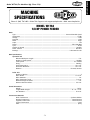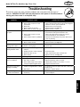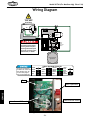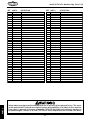
1
MODEL W1764
1/8 HP POWER FEEDER
OWNER'S MANUAL
(FOR MODELS MANUFACTURED SINCE 1/14)
Phone: (360) 734-3482 • Online Technical Support: [email protected]
COPYRIGHT © JUNE, 2007 BY WOODSTOCK INTERNATIONAL, INC. REVISED FEBRUARY, 2014 (BL)
WARNING: NO PORTION OF THIS MANUAL MAY BE REPRODUCED IN ANY SHAPE OR FORM WITHOUT
THE WRITTEN APPROVAL OF WOODSTOCK INTERNATIONAL, INC.
#9695CR Printed in Taiwan
This manual provides critical safety instructions on the proper setup,
operation, maintenance, and service of this machine/tool. Save this
document, refer to it often, and use it to instruct other operators.
Failure to read, understand and follow the instructions in this manual
may result in fire or serious personal injury—including amputation,
electrocution, or death.
The owner of this machine/tool is solely responsible for its safe use.
This responsibility includes but is not limited to proper installation in
a safe environment, personnel training and usage authorization,
proper inspection and maintenance, manual availability and comprehension, application of safety devices, cutting/sanding/grinding tool
integrity, and the usage of personal protective equipment.
The manufacturer will not be held liable for injury or property
damage from negligence, improper training, machine modifications or
misuse.
Some dust created by power sanding, sawing, grinding, drilling, and
other construction activities contains chemicals known to the State of
California to cause cancer, birth defects or other reproductive harm.
Some examples of these chemicals are:
• Lead from lead-based paints.
• Crystalline silica from bricks, cement and other masonry products.
• Arsenic and chromium from chemically-treated lumber.
Your risk from these exposures varies, depending on how often you
do this type of work. To reduce your exposure to these chemicals:
Work in a well ventilated area, and work with approved safety equipment, such as those dust masks that are specially designed to filter
out microscopic particles.
INTRODUCTION......................................2
Woodstock Technical Support................... 2
SETUP............................................... 11
Unpacking........................................ 11
Inventory......................................... 11
Cleaning Machine................................ 12
Assembly.......................................... 13
Base Mounting................................... 16
Test Run........................................... 18
SERVICE............................................. 22
General........................................... 22
Wheel Replacement............................ 22
Brush Replacement............................. 22
Troubleshooting.................................. 23
Wiring Diagram.................................. 24
PARTS............................................... 25
ELECTRICAL
ELECTRICAL..........................................9
Circuit Requirements............................. 9
Grounding Requirements....................... 10
Extension Cords................................. 10
MAINTENANCE..................................... 21
General........................................... 21
Cleaning.......................................... 21
Lubrication....................................... 21
SAFETY
SAFETY................................................6
Standard Machinery Safety Instructions....... 6
Additional Safety for Power Feeders........... 8
OPERATIONS....................................... 19
General........................................... 19
Power Feeder Accessories..................... 20
INTRODUCTION
Contents
WARRANTY......................................... 29
SET UP
OPERATIONS
MAINTENANCE
SERVICE
PARTS
USE THE QUICK GUIDE PAGE LABELS TO SEARCH OUT INFORMATION FAST!
INTRODUCTION
Model W1764 (For Machines Mfg. Since 1/14)
INTRODUCTION
Woodstock Technical Support
Woodstock International, Inc. is committed to customer satisfaction. Our intent with this manual is to
include the basic information for safety, setup, operation, maintenance, and service of this product.
In the event that questions arise about your machine, please contact Woodstock International Technical
Support at (360) 734-3482 or send e-mail to: [email protected]. Our knowledgeable staff will
help you troubleshoot problems or process warranty claims.
If you need the latest edition of this manual, you can download it from http://www.shopfox.biz.
If you have comments about this manual, please contact us at:
Woodstock International, Inc.
Attn: Technical Documentation Manager
P.O. Box 2309
Bellingham, WA 98227
Email: [email protected]
-2-
MACHINE
MACHINE
SPECIFICATIONS
SPECIFICATIONS
Phone #: (360) 734–3482 • Online Tech Support: tech–[email protected] • Web: www.shopfox.biz
MODEL W1764
1/8 HP POWER FEEDER
Motor
Type ................................................................................................. Universal Variable Speed
Horsepower .............................................................................................................. 1/8 HP
Voltage ...................................................................................................................... 120V
Prewired ..................................................................................................................... 120V
Phase....................................................................................................................... Single
Amps ......................................................................................................................... 1.2A
Speed ............................................................................................................ 550—3300 RPM
Cycle ........................................................................................................................ 60 Hz
Number of Speeds .................................................................................................... Variable
Power Transfer ...................................................................................................... Gear Box
Bearings ................................................................................................... Lubricated for Life
Main Specifications
Operation Info
Minimum Workpiece Length ....................................................................................... 5 in.
Number of Feed Speeds ....................................................................................... Variable
Feed Speeds ................................................................................................. 6.5—39 FPM
Swing ............................................................................................................ 360 deg.
Vertical Movement ........................................................................................... 10-1/4 in.
Horizontal Movement ........................................................................................ 10-1/4 in.
Rotation .............................................................................................. Forward, Reverse
Roller Info
Number of Rollers ....................................................................................................... 3
Roller Width ................................................................................................... 1–3/16 in.
Roller Diameter ..................................................................................................... 3 in.
Roller Suspension Travel ...................................................................................... 5/16 in.
Maximum Height of Rollers ....................................................................................... 6 in.
Distance Between Rollers .................................................................................... 3–3/4 in.
Overall Dimensions
Weight.............................................................................................................. 20 lbs.
Length/Width/Height ................................................................................. 31 x 11 x 12 in.
Arm Diameter ................................................................................................. 15/16 in.
Construction Materials
Roller Construction ................................................................................. Synthetic Rubber
Housing Construction .................................................................................. Cast Aluminum
Supports Construction ................................................................................. Cast Aluminum
Column Construction .............................................................................................. Steel
Paint ................................................................................................................. Epoxy
Model W1764 Specifications, Page 1 of 2, Last Updated 1/24/14
-3-
INTRODUCTION
Model W1764 (For Machines Mfg. Since 1/14)
INTRODUCTION
Model W1764 (For Machines Mfg. Since 1/14)
Shipping Dimensions
Type .................................................................................................................. Cardboard
Content ................................................................................................................. Machine
Weight .................................................................................................................... 27 lbs.
Length/Width/Height ........................................................................................ 11 x 22 x 9 in.
Electrical
Switch ................................................................................................ On/Off Variable Speed
Switch Voltage ............................................................................................................ 120V
Cord Length................................................................................................................ 7 ft.
Cord Gauge ..............................................................................................................18 AWG
Recommended Breaker Size.............................................................................................. 15A
Included Plug ................................................................................................................. Yes
Other
ISO Factory ............................................................................................................ ISO 9001
Country of Origin ...................................................................................................... Taiwan
Warranty ................................................................................................................ 2 Years
Assembly Time .....................................................................................................20 Minutes
Optional Accessories
Quick Holder ...................................................................................................... Model D3868
Extra Roller ....................................................................................................... Model D3870
Features
Spring Tensioned Rollers
Heavy–Duty Gear Reduction Gearbox with Hardened Gears
Universal Positioning with Handle Locks
Model W1764 Specifications, Page 2 of 2, Last Updated 6/7/12
-4-
INTRODUCTION
Model W1764 (For Machines Mfg. Since 1/14)
Controls and Features
Rotation
Position
Lock Lever
Horizontal
Position
Lock Lever
Dust Port
⁄8 HP
Motor
1
Vertical
Position
Lock Lever
Horizontal
Movement
Crank
Power Feeder Handle
Ball Joint
Lock Handle
Figure 22. Controls and features.
To reduce your risk of
serious injury, read this
entire manual BEFORE
using machine.
-5-
Model W1764 (For Machines Mfg. Since 1/14)
SAFETY
SAFETY
For.Your.Own.Safety,
Read.Manual.Before.Operating.Machine
The. purpose. of. safety. symbols. is. to. attract. your. attention. to. possible. hazardous. conditions.. This.
manual.uses.a.series.of.symbols.and.signal.words.intended.to.convey.the.level.of.importance.of.the.
safety.messages..The.progression.of.symbols.is.described.below..Remember.that.safety.messages.by.
themselves. do. not. eliminate. danger. and. are. not. a. substitute. for. proper. accident. prevention. measures—this.responsibility.is.ultimately.up.to.the.operator!
Indicates.an.imminently.hazardous.situation.which,.if.not.avoided,.
WILL.result.in.death.or.serious.injury.
Indicates.a.potentially.hazardous.situation.which,.if.not.avoided,.
COULD.result.in.death.or.serious.injury.
Indicates.a.potentially.hazardous.situation.which,.if.not.avoided,.
MAY.result.in.minor.or.moderate.injury.
NOTICE
This.symbol.is.used.to.alert.the.user.to.useful.information.about.
proper.operation.of.the.equipment.or.a.situation.that.may.cause.
damage.to.the.machinery.
Standard
Machinery Safety Instructions
Standard.Machinery.Safety.Instructions
OWNER’S.MANUAL..Read and understand this
owner’s manual BEFORE using machine.
ELECTRICAL.EQUIPMENT.INJURY.RISKS..You can
be shocked, burned, or killed by touching live
electrical components or improperly grounded
machinery. To reduce this risk, only allow an
electrician or qualified service personnel to
do electrical installation or repair work, and
always disconnect power before accessing or
exposing electrical equipment.
TRAINED.OPERATORS.ONLY..Untrained operators
have a higher risk of being hurt or killed. Only
allow trained/supervised people to use this
machine. When machine is not being used,
disconnect power, remove switch keys, or
lock-out machine to prevent unauthorized
use—especially around children. Make
workshop kid proof!
DISCONNECT.POWER.FIRST..Always disconnect
machine from power supply BEFORE making
adjustments, changing tooling, or servicing
machine. This eliminates the risk of injury
from unintended startup or contact with live
electrical components.
DANGEROUS.ENVIRONMENTS..Do not use
machinery in areas that are wet, cluttered,
or have poor lighting. Operating machinery
in these areas greatly increases the risk of
accidents and injury.
EYE.PROTECTION..Always wear ANSI-approved
safety glasses or a face shield when operating
or observing machinery to reduce the risk of
eye injury or blindness from flying particles.
Everyday eyeglasses are not approved safety
glasses.
MENTAL.ALERTNESS.REQUIRED..Full mental
alertness is required for safe operation of
machinery. Never operate under the influence
of drugs or alcohol, when tired, or when
distracted.
-6-
Model W1764 (For Machines Mfg. Since 1/14)
FORCING.MACHINERY..Do not force machine. It
will do the job safer and better at the rate for
which it was designed.
NEVER.STAND.ON.MACHINE..Serious injury may
occur if machine is tipped or if the cutting
tool is unintentionally contacted.
HAZARDOUS.DUST..Dust created while using
machinery may cause cancer, birth defects,
or long-term respiratory damage. Be aware of
dust hazards associated with each workpiece
material, and always wear a NIOSH-approved
respirator to reduce your risk.
STABLE.MACHINE..Unexpected movement during
operation greatly increases risk of injury or
loss of control. Before starting, verify machine
is stable and mobile base (if used) is locked.
USE.RECOMMENDED.ACCESSORIES..Consult
this owner’s manual or the manufacturer for
recommended accessories. Using improper
accessories will increase risk of serious injury.
HEARING.PROTECTION..Always wear hearing
protection when operating or observing
loud machinery. Extended exposure to this
noise without hearing protection can cause
permanent hearing loss.
UNATTENDED.OPERATION..To reduce the risk
of accidental injury, turn machine OFF and
ensure all moving parts completely stop
before walking away. Never leave machine
running while unattended.
REMOVE.ADJUSTING.TOOLS..Tools left on
machinery can become dangerous projectiles
upon startup. Never leave chuck keys,
wrenches, or any other tools on machine.
Always verify removal before starting!
MAINTAIN.WITH.CARE..Follow all maintenance
instructions and lubrication schedules to
keep machine in good working condition. A
machine that is improperly maintained could
malfunction, leading to serious personal injury
or death.
INTENDED.USAGE..Only use machine for its
intended purpose—never make modifications
without prior approval from Woodstock
International. Modifying machine or using
it differently than intended will void the
warranty and may result in malfunction or
mechanical failure that leads to serious
personal injury or death!
CHECK.DAMAGED.PARTS..Regularly inspect
machine for any condition that may affect
safe operation. Immediately repair or replace
damaged or mis-adjusted parts before
operating machine.
AWKWARD.POSITIONS..Keep proper footing and
balance at all times when operating machine.
Do not overreach! Avoid awkward hand
positions that make workpiece control difficult
or increase the risk of accidental injury.
CHILDREN.&.BYSTANDERS..Keep children and
bystanders at a safe distance from the work
area. Stop using machine if they become a
distraction.
MAINTAIN.POWER.CORDS..When disconnecting
cord-connected machines from power, grab
and pull the plug—NOT the cord. Pulling the
cord may damage the wires inside, resulting
in a short. Do not handle cord/plug with wet
hands. Avoid cord damage by keeping it away
from heated surfaces, high traffic areas, harsh
chemicals, and wet/damp locations.
GUARDS.&.COVERS..Guards and covers reduce
accidental contact with moving parts or flying
debris—make sure they are properly installed,
undamaged, and working correctly.
EXPERIENCING.DIFFICULTIES..If at any time
you experience difficulties performing the
intended operation, stop using the machine!
Contact Technical Support at (360) 734-3482.
-7-
SAFETY
WEARING.PROPER.APPAREL..Do not wear
clothing, apparel, or jewelry that can become
entangled in moving parts. Always tie back
or cover long hair. Wear non-slip footwear to
avoid accidental slips, which could cause loss
of workpiece control.
Model W1764 (For Machines Mfg. Since 1/14)
SAFETY
Additional Safety for Power Feeders
MAIN.INJURY.HAZARDS:.Death,.amputation,.or.crushing.injuries.from.getting.entangled.in.
moving.parts—which.may.include.being.pulled.into.the.cutting.tool.on.attached.machinery;.
death,.blindness,.broken.bones,.or.bruises.from.being.struck.by.an.ejected.workpiece.
(kickback)..To.minimize.your.risk.of.these.hazards,.always.heed.the.following.information:
ATTACHED.MACHINERY. Follow all warnings and
safety information for the attached machine
doing the cutting work.
FEATHERBOARD. When cutting long or large
stock that is difficult to feed properly, use
a featherboard before powerfeeder (on the
infeed side) to maintain even pressure and
control of workpiece against fence, and help
reduce risk of kickback.
HAND.SAFETY. Keep hands away from rotating
parts on power feeder and spinning blade
or cutter of associated machine. Turn power
feeder and associated machine OFF and only
use a brush or compressed air to remove
sawdust.
FEED.WORKPIECE.PROPERLY..Verify blade or
cutter of associated machine is at full speed
before feeding stock with power feeder.
Do not feed workpiece too quickly. Verify
power feeder wheels are slightly lower than
workpiece. Stop power feeder before stopping
cutting tool.
INSTALLING.GUARDS. Install guards, fences, and
hold-downs before starting attached machine
or power feeder. Repair or replace guards
promptly if they become damaged.
WORKPIECE.SUPPORT. Support workpiece
continuously during operation as required. Use
auxiliary stands or support tables for long or
wide stock.
KICKBACK. Occurs when workpiece is ejected
from machine with great force, striking
operator or bystanders. Commonly caused by
improper machine or power feeder setup.
ADJUSTMENTS/MAINTENANCE. Make sure power
feeder is turned OFF, disconnected from
power, and all moving parts are completely
stopped before doing adjustments or
maintenance.
VERIFY.EACH.SETUP. Ensure that power feeder
is set up correctly and firmly secured before
feeding workpiece. An improperly adjusted
power feeder could increase the risk of
kickback, because it will continue feeding
when stock is not properly positioned for the
cut.
READ and understand this
entire manual before using
this machine. Serious personal injury may occur
if safety and operational
information is not understood and followed. DO
NOT risk your safety by
not reading!
USE this and other machinery with caution and respect. Always consider safety
first, as it applies to your individual working conditions. No list of safety guidelines
can be complete—every shop environment
is different. Failure to follow guidelines
could result in serious personal injury,
damage to equipment or poor work results.
-8-
Model W1764 (For Machines Mfg. Since 1/14)
ELECTRICAL
Circuit Requirements
This machine must be connected to the correct size and
type of power supply circuit, or fire or electrical damage
may occur. Read through this section to determine if an
adequate power supply circuit is available. If a correct
circuit is not available, a qualified electrician MUST install
one before you can connect the machine to power.
The. machine. must. be. properly. set. up.
before. it. is. safe. to. operate.. DO. NOT.
connect. this. machine. to. the. power.
source.until.instructed.to.do.so.later.in.
this.manual.
ELECTRICAL
A power supply circuit includes all electrical equipment
between the breaker box or fuse panel in the building
and the machine. The power supply circuit used for
this machine must be sized to safely handle the fullload current drawn from the machine for an extended
period of time. (If this machine is connected to a circuit
protected by fuses, use a time delay fuse marked D.)
Full-Load Current Rating
The full-load current rating is the amperage a machine
draws at 100% of the rated output power. On machines
with multiple motors, this is the amperage drawn by the
largest motor or sum of all motors and electrical devices
that might operate at one time during normal operations.
Full-Load Current Rating at 120V.................. 1.2 Amps
Circuit Requirements for 120V
This machine can be converted to operate on a 110V
power supply (details about voltage conversion can be
found later in this manual). The 110V power supply circuit
must have a verified ground and meet the requirements
that follow:
Circuit Type....................... 120V, 60 Hz, Single-Phase
Circuit Size.............................................. 15 Amps
Plug/Receptacle..................................... NEMA 5-15
-9-
Incorrectly. wiring. or. grounding. this.
machine.can.cause.electrocution,.fire,.
or.machine.damage..To.reduce.this.risk,.
only.an.electrician.or.qualified.service.
personnel. should. do. any. required.
electrical.work.on.this.machine.
NOTICE
The. circuit. requirements. listed. in. this.
manual. apply. to. a. dedicated. circuit—
where.only.one.machine.will.be.running.
at. a. time.. If. this. machine. will. be.
connected. to. a. shared. circuit. where.
multiple.machines.will.be.running.at.the.
same.time,.consult.with.an.electrician.
to. ensure. that. the. circuit. is. properly.
sized.for.safe.operation.
Model W1764 (For Machines Mfg. Since 1/14)
Grounding Requirements
ELECTRICAL
This machine MUST be grounded. In the event of certain
types of malfunctions or breakdowns, grounding provides
a path of least resistance for electric current to travel—in
order to reduce the risk of electric shock.
Improper connection of the equipment-grounding wire will
increase the risk of electric shock. The wire with green
insulation (with/without yellow stripes) is the equipmentgrounding wire. If repair or replacement of the power
cord or plug is necessary, do not connect the equipmentgrounding wire to a live (current carrying) terminal.
120V
GROUNDED
5-15 RECEPTACLE
Grounding Prong
5-15 PLUG
Neutral Hot
Figure 23. NEMA 5-15 plug & receptacle.
Check with a qualified electrician or service personnel
if you do not understand these grounding requirements,
or if you are in doubt about whether the tool is
properly grounded. If you ever notice that a cord or
plug is damaged or worn, disconnect it from power, and
immediately replace it with a new one.
For 120V Connection
This machine is equipped with a power cord that has an
equipment-grounding wire and NEMA 5-15 grounding plug.
The plug must only be inserted into a matching receptacle
(see Figure) that is properly installed and grounded in
accordance with local codes and ordinances.
Extension Cords
We do not recommend using an extension cord with
this machine. Extension cords cause voltage drop, which
may damage electrical components and shorten motor
life. Voltage drop increases with longer extension cords
and smaller gauge sizes (higher gauge numbers indicate
smaller sizes).
Any extension cord used with this machine must contain a
ground wire, match the required plug and receptacle, and
meet the following requirements:
Minimum Gauge Size at 120V....................... 14 AWG
Maximum Length (Shorter is Better).................50 ft.
-10-
DO NOT modify the provided plug or
use an adapter if the plug will not
fit the receptacle. Instead, have an
electrician install the proper receptacle
on a power supply circuit that meets
the requirements for this machine.
Model W1764 (For Machines Mfg. Since 1/14)
SETUP
Unpacking
This machine has been carefully packaged for safe
transportation. If you notice the machine has been
damaged during shipping, please contact your authorized
Shop Fox dealer immediately.
Inventory
The following is a description of the main components
shipped with the Model W1764. Lay the components out
to inventory them.
Keep machine disconnected from
power until instructed otherwise.
Qty
Box Inventory (Figures 24 & 25)
A.Base...........................................................1
B. Arm Bracket.................................................1
C. Power Feeder Unit.........................................1
D.Arm...........................................................1
E. Base Mounting Template..................................1
F. Elbow Clamp Assembly....................................1
G. Ball Joint Assembly.........................................1
H. Hardware Bag (Figure 25)................................1
—Cap Screw M10-1.5 x 25mm (Elbow Clamp)..........1
—Hex Bolt M10-1.5 x 50mm (Elbow Clamp)............3
—Lock Lever (Arm Bracket Clamp)......................1
—Hex Nut M8-1.25mm (Arm Bracket Clamp)...........1
—Flat Washer 8mm (Arm Bracket Clamp) .............1
—T-Handle and Pivot Bar (Ball Joint Assembly)........1
—Hex Bolt M10-1.5 x 35mm (Base)......................4
—Lock Washer 10mm (Base)..............................8
—Hex Nut M10-1.5mm (Base).............................7
C
B
A
D
E
F
G
H
Figure 24. Box inventory.
H
Figure 25. Hardware inventory.
-11-
SETUP
Note: If you can't find an item on this list, check the
mounting location on the machine or examine the
packaging materials carefully. Occasionally we pre-install
certain components for safer shipping.
Model W1764 (For Machines Mfg. Since 1/14)
Cleaning Machine
To prevent corrosion during shipment and storage of your
machine, the factory has coated the bare metal surfaces
of your machine with a heavy-duty rust prevention
compound.
If you are unprepared or impatient, this compound can
be difficult to remove. To ensure that the removal of this
coating is as easy as possible, please gather the correct
cleaner, lubricant, and tools listed below:
•
•
•
•
Cleaner/degreaser designed to remove storage wax
and grease
Safety glasses & disposable gloves
Solvent brush or paint brush
Disposable Rags
SETUP
To. remove. the. rust. preventative. coating,. do. these.
steps:
1.
DISCONNECT THE MACHINE FROM POWER!
2.
Put on safety glasses and disposable gloves.
3.
Using a liberal amount of your cleaner/degreaser,
Coat all surfaces that have the coating, and let soak
for few minutes.
4.
Wipe off the surfaces. If your cleaner/degreaser is
effective, the coating will wipe off easily.
Tip: To clean off thick coats of the rust preventative
compound on flat surfaces, use a PLASTIC paint
scraper to scrape off the majority of the coating
before wiping it off with your rag. (Do not use a
metal scraper or you may scratch your machine.)
5.
Repeat the cleaning steps as necessary until all of
the compound is removed.
6.
To prevent rust on the freshly cleaned surfaces,
immediately coat with a quality metal protectant.
-12-
Gasoline.and.petroleum.
products.have.low.flash.
points.and.can.explode.
or.cause.fire.if.used.to.
clean.machinery..Avoid.
using. these. products.
to. clean. machinery..
Many. cleaning. solvents.
are. toxic. if. inhaled..
Minimize. your. risk.
by. only. using. these.
products. in. a. well.
ventilated.area.
NOTICE
In. a. pinch,. automotive. degreasers,.
mineral.spirits.or.WD•40.can.be.used.
to. remove. rust. preventative. coating..
Before. using. these. products,. though,.
test.them.on.an.inconspicuous.area.of.
your.paint.to.make.sure.they.will.not.
damage.it.
Model W1764 (For Machines Mfg. Since 1/14)
Assembly
To correctly position this power feeder on your table top,
completely assemble the power feeder first, then refer
to Base Mounting on Page 16. With the power feeder
unit completely assembled, it will be easier to determine
where on the table top to drill your base mounting holes,
so you can take advantage of the full range of power
feeder swing and adjustments.
T-Handle
To assemble the power feeder, do these steps:
Elbow
Clamp
1. Oil the T-handle threads and position the elbow
clamp assembly onto the feeder base, as shown in
Figure 26.
Feeder
Base
2. Thread the T-handle into the feeder base until the
elbow is snug.
4. Insert the ball joint assembly into the power feed
socket shown in Figure 27.
Power Feed
Socket
Arm
Ball-Joint Ball
5. Insert the ball-joint socket into the power feed
socket as shown in Figure 28, so it rests against the
ball-joint ball.
Note: Lubrication is not necessary for the ball joint
assembly.
Cap Screw
6. Align the ball-joint socket with the power feeder
socket and insert the pivot bar, as shown in Figure
28.
Figure 27. Arm, ball joint and socket
assembly.
7. Lightly oil the T-handle threads.
Ball-Joint Socket
8. Thread the T-handle through the pivot bar so the
end of the T-handle bolt presses against the balljoint socket firmly, as shown in Figure 28.
Pivot Bar
T-Handle
Figure 28. Assembled ball joint assembly.
-13-
SETUP
3. Insert the arm into the ball-joint ball and secure
both together with the M10-1.5 x 25mm cap screw
shown in Figure 27.
Figure 26. Assembled elbow clamp
assembly.
Model W1764 (For Machines Mfg. Since 1/14)
9. Place the arm into the arm bracket so the teeth of
the gear and arm mesh, as shown in Figure 29.
Arm Bracket
Arm
Note: No lubrication is required for the gear or rack
teeth. Oil or grease will gather debris making the
horizontal adjustment of the power feeder difficult.
10.Secure the arm bracket cover onto the arm bracket
with three M10-1.5 x 35 hex bolts and washers (see
Figure 30).
Note: Make sure that you do not tighten the hex
bolts so much as to prevent the arm from sliding
in and out of the arm bracket when the horizontal
crank is turned.
Spline
Figure 29. Arm bracket gearing.
SETUP
11.Insert the horizontal crank completely so it engages
the spline (Figure 29) in the gear.
Lock Lever
Flat Washer
12.Insert the lock lever, flat washer, and hex nut, as
shown in Figure 30.
13.Place the E-clip on the end of the horizontal crank
to retain the crank, as shown in Figure 31.
14.Turn the horizontal crank to make sure that the
cover bolts are not too tight or too lose. Adjust the
three hex bolts as required to achieve a slight drag
between the arm and arm bracket.
Hex Nut
Arm Bracket
Cover
Horizontal Crank
Figure 30. Assembling arm bracket.
Continued on next page
E-Clip
Figure 31. Horizontal movement handle
E-clip.
-14-
Model W1764 (For Machines Mfg. Since 1/14)
15. Lightly oil the T-handle threads shown in Figure 32.
Note: No lubrication is required for the arm bracket
and the elbow clamp connection.
Oil Threads
16. Position the arm bracket onto the elbow clamp, as
shown in Figure 33.
17. Thread the T-handle into the elbow clamp so both
assemblies are secure, as shown in Figure 33.
18. Use the levers to lock the power feeder into
position, such as the example shown in Figure 34.
Figure 32. Arm bracket handle threads.
Arm Bracket
SETUP
T-Handle
Elbow
Clamp
Figure 33. Arm bracket and elbow clamp
assembly.
Model D3868 Quick Holder
Figure 34. Typical power feed mounting
using an optional Model D3868 Quick
Holder.
-15-
Model W1764 (For Machines Mfg. Since 1/14)
Base Mounting
Assemble the power feeder before you mount the
base to determine where on the table top to drill
your base mounting holes, so you can maximize
power feeder swing and adjustment options.
Also, you must be able to adjust the power
feeder so it points towards the machine fence
slightly (see Figure 35). In other words, the
tracking of the power feeder must be toed-in
approximately 1° to 1.5° degrees toward the
machine fence, so the power feeder wheels push
the workpiece against the fence slightly during
cutting operations.
There are three mounting options available,
Through-Bolt Mounting, Direct Mounting, and
Quick Holder Mounting options discussed on Page
17. Choose an option that suits your requirements.
If cutting long or large stock that is difficult to
feed properly, use a featherboard before the
power feeder (on the infeed side) to maintain
even pressure and control of the workpiece
against the fence.
SETUP
Your final goal is to be able to use the handcranks
and lock levers to position the power feeder
wheels so they are parallel with the table
surface, and 1⁄8" lower than the thickness of your
workpiece.
Shaper
Table Saw
Jointer
Fence
Fence
Fence
Blade
Optional
Featherboard
Cutter
Feed
4th-Roller
Models
Feed
Feed
Cutterhead
Figure 35. Typical power feed mounting on a shaper, jointer, and tablesaw.
Continued on next page
-16-
Model W1764 (For Machines Mfg. Since 1/14)
Through-Bolt Mounting
We recommend that you mount your new power feeder to
the machine table with through-bolts, nuts and washers
(see Figure 36). This option will give the most rigidity
and clamping strength to prevent the feeder base from
twisting out of alignment during use. However, if the
included mounting bolt template shows that any undertable support webs will interfere with any washer or nut
locations under the table, you will have to use an optional
clamping kit such as the Model D3868 Quick Holder
(see Accessories on Page 20), or drill and thread holes
directly into the table as described in Direct Mounting.
Direct Mounting
Flat Washer
Machine Table
Table
Support
Webbing
Flat Washer
Lock Washer
Locking Hex Nut
Figure 36. Through-bolt mounting.
Feeder
Base
Bolt
Lock Washer
Flat Washer
Machine Table
Quick Holder Mounting
For temporary or permanent installation of your power
feeder without drilling into the table, you can purchase
and install the Model D3868 Quick Holder Kit (see Figure
38). These kits, while not as rigid as the through-bolt
or direct mount options, require no drilling or tapping,
and are adequate for most power feeder applications.
Make sure to use a medium-grade liquid thread locking
compound on all threads.
Bolt
Table
Support
Webbing
Apply A Medium
Grade Thread
Locking Compound
To The Threads
Figure 37. Direct mounting.
Feeder
Base
Bolt
Lock Washer
Quick Holder
Machine Table
Apply A Medium
Grade Thread
Locking Compound
To The Threads
Quick
Holder
Figure 38. Quick holder mounting.
-17-
SETUP
Use the included mounting template to drill and tap your
table, so the power feeder base can be directly mounted
to the table surface (see Figure 37). If the table is
thinner than 3⁄8" thick where the threaded holes would
be drilled and tapped, or if support webbing is in the
way, the threads may strip or loosen as the power feeder
is used. Thread locking compound will not cure this
problem. Revert to the Through-Bolt Mounting option or
the Quick Holder Mounting if the table is too thin or if
support webbing is in the way. In any case, make sure to
use a medium-grade liquid thread locking compound on all
threads.
Feeder
Base
Model W1764 (For Machines Mfg. Since 1/14)
Test Run
Once the power feeder assembly is complete and
mounted on the table, you must test run your power
feeder to make sure it runs properly.
If, during the test run, you cannot easily locate the source
of an unusual noise or vibration, stop using the power
feeder immediately, then review the Troubleshooting
table on Page 23.
If you still cannot remedy a problem, contact our
Technical Support at (360) 734-3482 for assistance.
Projectiles thrown from the machine
could cause serious eye injury. Wear
safety glasses to reduce the risk of
injury.
To test run the power feed, do these steps:
1. Read the entire instruction manual first!
SETUP
2. Make sure all tools and foreign objects have been
removed from the tabletop area.
3. Make sure the speed dial (Figure 39) is pushed IN
and turned all the way to the left.
4. Make sure the feed direction rocker switch (Figure
39) is in the central position.
5. Adjust the power feeder so all wheels are approximately 1" above the table surface.
Loose hair and clothing could get
caught in machinery and cause serious
personal injury. Keep loose clothing
rolled up and long hair tied up and
away from machinery.
6.Connect the power feeder to the power source.
7. Push the feed direction rocker switch to the left or
right.
Speed Dial
8. Pull the speed dial out all the way. The power feed
should run slowly and smoothly with little or no
vibration.
Feet Per
Minute
Scale
ON
OFF
9. Slowly turn the speed dial clockwise. The speed of
the wheels should increase respectively.
10.Turn the speed dial back to zero, push the rocker
switch the opposite direction, then turn the speed
dial clockwise until the wheels turn. They should
rotate the opposite direction as before.
11.Turn the power feeder OFF and move the rocker
switch to the central position. The test run is complete.
Meters Per
Minute
Scale
Feed Direction
Rocker Switch
Figure 39. Feeder motor controls.
-18-
Model W1764 (For Machines Mfg. Since 1/14)
OPERATIONS
General
This machine will perform many types of operations that
are beyond the scope of this manual. Many operations can
be dangerous or deadly if performed incorrectly.
The instructions in this section are written with the understanding that the operator has the necessary knowledge
and skills to operate this machine. If at any time you experience difficulties performing any operation, stop
using the machine!
If you are an inexperienced operator, we strongly recommend that you read books, trade articles, or seek training
from an experienced power feeder operator before performing any unfamiliar operations. Above all, your safety
should come first!
Basic Use and Care
OPERATIONS
Power feeders reduce kickback hazards and improve
cutting results by feeding in a consistent and stable
manner. Remember, do not to stand in path of potential
kickback. When not in use, support power feeder with a
wooden block so rubber wheels are raised above table
and do not compress from weight of power feeder.
READ and understand this entire instruction manual before using this machine.
Serious personal injury may occur if
safety and operational information is not
understood and followed. DO NOT risk
your safety by not reading!
Universal joints on this power feeder allow you to adjust
power feeder tracking and height to accommodate many
workpiece sizes. Before loosening any lock lever, always
support power feeder with a block of wood, so power
feeder does not drop and cause damage.
Adjust power feeder so it is toed-in approximately 1° to
1.5° degrees towards machine fence. This adjustment
will ensure power feeder wheels slightly push workpiece
against fence during cutting operations (see Figure 35 on
Page 16). A featherboard may be used on infeed side to
help feed long or large stock.
Next, adjust power feeder so rubber wheels are parallel
with table surface, and are 1⁄8" lower than thickness of
your workpiece. This adjustment ensures that workpiece
will not slip or hang in middle of a cut. Always double
check that power feeder wheels are slightly lower
than workpiece before you begin feeding operations.
Otherwise, workpiece may slip and kickback. For machine
operations that generate a lot of dust, remove plastic
knock-out plug at bottom of port and connect a 13⁄8"
inside diameter shop vacuum hose.
-19-
DO NOT investigate problems or adjust
the machine while it is running. Wait
until the machine is turned OFF,
unplugged and all working parts
have come to a complete stop before
proceeding!
Always wear safety glasses when operating this machine. Failure to comply
may result in serious personal injury.
Model W1764 (For Machines Mfg. Since 1/14)
Power Feeder Accessories
The following power feeder accessories may be available through your local Woodstock International
Inc. Dealer. If you do not have a dealer in your area, these products are also available through online
dealers. Please call or e-mail Woodstock International Inc. Customer Service to get a current listing of
dealers at: 1-800-840-8420 or at [email protected].
The Model D3868 Shop Fox Quick Holder Kit is adequate for
most power feeder applications, and can be used for permanent or
temporary power feeder mounting. This kit requires no drilling or
tapping of your machine table.
The Model D3870 Extra Roller adds insurance against downtime
should a workpiece damage a wheel, or after long use the wheel
tire wears out. These wheels can be replaced in a few minutes.
D3868
D3870
OPERATIONS
The Model D3122 Push Stick keeps hands a safe distance from
blades and cutters while still maintaining control of the workpiece
against machine fences. A true necessity when running narrow stock.
Durable handle is designed for maximum control. Measures 131⁄2"
overall.
The Model D3096 Shop Fox Featherboard helps reduce the risk
of kick-back and achieve consistent results. Designed to lock into
standard 3⁄8" x 3⁄4" miter gauge slots, this Featherboard is adjustable
for various stock widths and miter slot locations. No drilling or bulky
clamp arrangements!
The Model D2018 60-Pc. Tap & Die Set includes both coarse and
fine thread tap and dies. Tap and dies are numbered from #4 - 40 to
#12 - 24 and fractional taps and dies from 1⁄4" - 28 to 1⁄2" - 20 and
1
⁄8" - 27 NPT. Set includes thread gauge, tap handle, die handle and
small tap chuck, all in a nice molded case. Also includes metric taps
and dies from M3 x .5 to M12 x 1.75. Made of high carbon steel.
-20-
D3122
D3096
D2018
Model W1764 (For Machines Mfg. Since 1/14)
MAINTENANCE
General
Regular periodic maintenance on your machine will
ensure its optimum performance. Make a habit of
inspecting your machine each time you use it.
Check for the following conditions and repair or
replace when necessary:
•
•
•
Loose mounting bolts and damaged wheel rubber.
Worn or damaged, switch, cord, and plug.
Any other condition that could hamper the safe
operation of the power feeder.
Cleaning
•
Frequently blow-off sawdust with compressed air.
This is especially important for the internal working
parts and motor. Dust build-up around the motor is a
sure way to decrease its life span.
•
If the wheels become loaded up with pitch, oil, or
other residues, wipe them clean using a clean rag
and a mild solvent. Avoid touching the plastic or
paint with mineral spirits or you may damage the
surfaces.
MAKE SURE that your machine is
unplugged during all maintenance
procedures! If this warning is ignored,
serious personal injury may occur.
Lubrication
-21-
MAINTENANCE
Since all bearings are sealed and permanently lubricated,
simply leave them alone until they need to be replaced.
Do not lubricate them. However, periodically oil the lock
lever and T-handle threads to ensure free operation.
Wipe down the adjustment arm with a thin film of oil
as required to prevent surface rust, but not enough to
attract dirt.
Model W1764 (For Machines Mfg. Since 1/14)
SERVICE
General
This section covers the most common service adjustments
or procedures that may need to be made during the life
of your machine.
If you require additional machine service not included
in this section, please contact Woodstock International
Technical Support at (360) 734-3482 or send e-mail to:
[email protected].
Wheel Replacement
If you damage one or more wheels, you can easily replace
the wheels.
MAKE SURE that your machine is
unplugged during all service procedures! If this warning is ignored, serious personal injury may occur.
To replace the wheels, do these steps:
1. DISCONNECT THE MACHINE FROM POWER!
2. Remove the three cover screws and the cover (see
Figure 40).
3. Put on your safety glasses and remove the retaining
ring (see Figure 40) using external retaining ring
pliers.
4. Replace the wheel and reassemble the power feeder.
Figure 40. Wheel replacement.
Brush Replacement
SERVICE
After a long period of time you may notice the motor lose
some power or begin making "growling" sounds during
operation. This indicates that the motor brushes are
worn and need replacement. The brushes can be easily
replaced.
To replace the brush set, do these steps:
1. DISCONNECT THE MACHINE FROM POWER!
2. Unscrew both brush caps (see Figure 41) on either
side of the motor.
3. Replace the brush set (see Figure 41) and re-install
the caps.
-22-
Figure 41. Brush set replacement.
Model W1764 (For Machines Mfg. Since 1/14)
Troubleshooting
This section covers the most common problems and corrections with this type of
machine. WARNING! DO NOT make any adjustments until power is disconnected and
moving parts have come to a complete stop!
PROBLEM
POSSIBLE CAUSE
CORRECTIVE ACTION
Motor will not start.
1. Low voltage.
2. Open circuit in motor or loose
connections.
3. Blown fuse.
4. Motor brushes are at fault.
5. Motor switch or motor is at fault.
1. Check power supply for proper voltage.
2. Inspect all lead connections on motor and magnetic
switch for loose or open connections.
3. Replace fuse on circuit board.
4. Replace brushes (see Page 22).
5. Replace switch or motor.
Fuses or circuit breakers
trip open.
1. Short circuit in line cord or plug.
1. Inspect cord or plug for damaged insulation and
shorted wires and replace extension cord.
2. Inspect all connections on motor for loose or
shorted terminals or worn insulation.
3. Disconnect all machinery from power and correct
cause of jamming.
2. Short circuit in motor or loose
connections.
3. Power feeder rollers are jammed.
Motor overheats.
1. Motor overloaded.
2. Motor brushes at fault.
1. Reduce power feeder feed rate.
2. Replace brushes (see Page 22).
Workpiece jams when
feeding under rollers.
1. Rollers set too low.
2. Feeder at wrong angle.
1. Raise feeder.
2. Adjust angle.
Workpiece slips while
passing beneath rollers
1. Rollers positioned too high, no
traction.
2. Feeding too fast, cutter overloads.
3. Rollers are dirty or oily.
4. Worn roller(s).
1. Lower feeder.
Workpiece is burnt.
1. Wrong feed speed.
1. Adjust feed speed.
Rough finish or chipped
grain on workpiece.
1. Feed speed too fast.
2. Dull cutter or blade.
3. Power feeder angle is not toed in
to keep workpiece against fence.
1. Slow speed.
2. Replace with sharp cutter or blade.
3. Adjust power feeder so it is toed-in 1° to 1.5°
degrees toward the fence.
Fuzzy grain occurs when
planing or moulding.
1. Lumber has high moisture content. 1. If moisture content is higher than 20%, sticker and
allow to dry.
2. Dull knives.
2. Sharpen or replace knives.
Workpiece hangs and does
not enter the machine.
1. Power feeder roller height is set
incorrectly.
2. Slow feed speed.
3. Clean roller surface with a mild solvent.
4. Replace roller(s) (see Page 22).
1. Lower the power feeder 1⁄8" lower than the height
of the workpiece.
SERVICE
-23-
Model W1764 (For Machines Mfg. Since 1/14)
Wiring Diagram
120 VAC
5-15 Plug
Neutral
Hot
Fuse 3.15A
Ground
250VAC
Motor
Speed
Dial
Ground
SHOCK HAZARD!
Disconnect power before
servicing electrical parts.
Touching electrified parts
will result in severe burns,
electrocution, or death.
Power
Feed
Direction
Switch
Motor PC Board
Universal Brush
Type Motor
WIRING DIAGRAM COLOR KEY
The photos and diagrams
included in this section are
best viewed in color. You
can view these pages in
color at www.shopfox.biz.
BLACK
BLUE
WHITE
BROWN
GREEN
GRAY
YELLOW
YELLOW
GREEN
PURPLE
RED
ORANGE
PINK
LIGHT
BLUE
BLUE
WHITE
TURQUOISE
Fuse
SERVICE
Motor Speed Dial
Feed Direction Switch
Motor Control PC Board
Figure 42. Feeder Control System.
-24-
89
62
34
51
31
17
49
85
34
7
33
89
29
17 17
85
36
20
25
8
53
33
68
29
17 17
28
22
38
86V2
45
54
30
28
83
23
51
49
38
56
58 71
20
15
83
51
8
36
30
14
20
50
69
54
8
14
69
9
14
20
53
83
56
1
11
615
9
14
14
79
69
67
77
74
6
11
8
54
79
6
8 16
15
23
60
63
82
59
57
6
70
46
67
56
89
6
83
36
11
90
53
6
66
74
83
23
16
820
82
50
47
60
72
63
58
57
59
66
62
4970
45
86 47 46
67
38-1 72
38-2
39-2
62
39-1
88
71
61
38-1
38-2
39-2
70
46
83
40
7
47
22
31
2517
50
40-1 43
40
72
65
57
39-1
66
39
39-5
65
39-3
40-1
39-4
39
58
39-5
39-3
39-4
43
PARTS
45
86
38-1
-25-
38
38-2
39-2
39-1
71
61
61
16
11
15
8
1
83
69
19
9 9
6
16
9
14
1
19
79
75
80
81
1681
80
82
2011
15
60
77
59
74
75
63
11
18
80
12
15
12
1
84
14
8
15
36-1
12
84
76
16
1
19
15
12
19
19
9 9
37
83
14
16
37
81
76
7684V2
77
75
12
19
16
14
87
15
36-1
37
16
12
36-1
Model W1764 (For Machines Mfg. Since 1/14)
PARTS
PARTS
Model W1764 (For Machines Mfg. Since 1/14)
REF
PART #
1
6
7
8
9
11
12
14
15
16
17
19
20
22
23
25
28
29
30
31
33
34
36
36-1
37
38
38-1
38-2
39
39-1
39-2
39-3
39-4
39-5
40
40-1
43
45
X1764001
EXTRA ROLLER
X1764006
SPROCKET CASE
X1764007
TORTION SPRING 30 X 3
X1764008
BUSHING
X1764009
CASE CAP
X1764011
GEARKIT(25T)
X1764012
EXT RETAINING RING 22MM
X1764014
DRIVE SHAFT
X1764015
GEAR 10-TEETH
X1764016
E-CLIP 6.4MM
X1764017
EXT RETAINING RING 12MM
X1764019
SHAFT
X1764020
HEX NUT M8-1.25
X1764022
BEVEL GEAR
X1764023
KEY 5 X 5 X 20
X1764025
BEVEL GEAR CAP
X1764028
SPROCKET 10-TEETH
X1764029
BUSHING 14 X 21 X 10.5
X1764030
CHAIN (18S)
X1764031
CHAIN (24S)
X1764033
BACK COVER
X1764034
PHLP HD SCR M5-.8 X 16
X1764036
FRONT COVER
X1764036-1 HOUSING COVER
X1764037
PHLP HD SCR M5-.8 X 16
X1764038
CONTROL BOX KIT
X1764038-1 CONTROL BOX POWER CORD
X1764038-2 CONTROL BOX GROMMETS
X1764039
DC MOTOR 1/8HP
X1764039-1 MOTOR POWER CORD
X1764039-2 CABLE CLAMP
X1764039-3 BRUSH ASSEMBLY
X1764039-4 BRUSH CAP
X1764039-5 HOUSING
X1764040
MOTOR CONTROL SYSTEM
X1764040-1 FUSE 3.15, A 250VAC
X1764043
TAP SCREW M3-.5 X 8
X1764045
LOWER BALL HOUSING
DESCRIPTION
REF PART #
DESCRIPTION
46
47
49
50
51
53
54
56
57
58
59
60
61
62
63
65
66
67
69
70
71
72
74
75
76
77
79
80
81
82
83
84V2
85
86V2
87
88
89
90
STOPPER
UPPER BALL SOCKET
BALL
LOCK WASHER 10MM
CAP SCREW M10-1.5 X 25
SHAFT
T-HANDLE
ARM CLAMP
ARM CLAMP COVER
HEX BOLT M10-1.5 X 50
LOCK WASHER 10MM
HEX NUT M10-1.5
T-HANDLE
FLAT WASHER 18MM
HEX NUT M16-2
T-HANDLE
PINION GEAR
E-CLIP 5MM
CLAMP LEVER
FLAT WASHER 5/16
HEX NUT M8-1.25
ARM
ELBOW SWIVEL CONE
T-HANDLE
FLAT WASHER 18MM
HEX NUT M16-2
BASE
LOCK WASHER 10MM
HEX BOLT M10-1.5 X 35
LOCK WASHER 10MM
TORSION SPRING
MACHINE ID LABEL CSA V2.01.14
SHOP FOX LOGO LABEL
GENERAL WARNING LABEL V2.01.14
COMBO WARNING LABEL
ELECTRICITY LABEL 0.7W X 0.6H
DAMPNESS WARNING LABEL
SHOP FOX WHITE TOUCH-UP PAINT
X1764046
X1764047
X1764049
X1764050
X1764051
X1764053
X1764054
X1764056
X1764057
X1764058
X1764059
X1764060
X1764061
X1764062
X1764063
X1764065
X1764066
X1764067
X1764069
X1764070
X1764071
X1764072
X1764074
X1764075
X1764076
X1764077
X1764079
X1764080
X1764081
X1764082
X1764083
X1764084V2
X1764085
X1764086V2
X1764087
X1764088
X1764089
X1764090
Safety labels warn about machine hazards and how to prevent serious personal injury. The owner
of this machine MUST maintain the original location and readability of all labels on this machine.
If any label is removed or becomes unreadable, REPLACE that label before allowing machine to
be operated again. Contact us at (360) 734-3482 or www.shopfoxtools.com to order new labels.
-26-
CUT ALONG DOTTED LINE
Model W1764 (For Machines Mfg. Since 1/14)
Fold along dotted lIne
place
stamp
Here
Woodstock international inc.
p.o. box 2309
bellingham, Wa 98227-2309
Fold along dotted lIne
tape along edges--please do not staple
WARRANTY
WARRANTY
Woodstock International, Inc. warrants all Shop Fox machinery to be free of defects from workmanship
and materials for a period of two years from the date of original purchase by the original owner.
This warranty does not apply to defects due directly or indirectly to misuse, abuse, negligence or
accidents, lack of maintenance, or reimbursement of third party expenses incurred.
Woodstock International, Inc. will repair, replace, or arrange for a dealer refund, at its expense and
option, the Shop Fox machine or machine part proven to be defective for its designed and intended
use, provided that the original owner returns the product prepaid to an authorized warranty or repair
facility as designated by our Bellingham, Washington office with proof of their purchase of the product
within two years, and provides Woodstock International, Inc. reasonable opportunity to verify the
alleged defect through inspection. If it is determined there is no defect, or that the defect resulted
from causes not within the scope of Woodstock International Inc.'s warranty, then the original owner
must bear the cost of storing and returning the product.
This is Woodstock International, Inc.’s sole written warranty and any and all warranties that may be
implied by law, including any merchantability or fitness, for any particular purpose, are hereby limited
to the duration of this written warranty. We do not warrant that Shop Fox machinery complies with
the provisions of any law, acts or electrical codes. We do not reimburse for third party repairs. In no
event shall Woodstock International, Inc.’s liability under this limited warranty exceed the purchase
price paid for the product, and any legal actions brought against Woodstock International, Inc. shall be
tried in the State of Washington, County of Whatcom. We shall in no event be liable for death, injuries
to persons or property or for incidental, contingent, special or consequential damages arising from the
use of our products.
Every effort has been made to ensure that all Shop Fox machinery meets high quality and durability
standards. We are commited to continuously improving the quality of our products, and reserve the
right to change specifications at any time.
High Quality Machines and Tools
Woodstock International, Inc. carries thousands of products designed
to meet the needs of today's woodworkers and metalworkers.
Ask your dealer about these fine products: