1
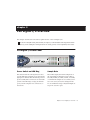
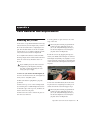
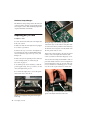
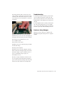
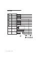
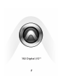
192 Digital I/O™
Copyright
© 2006 Digidesign, a division of Avid Technology, Inc. All rights
reserved. This guide may not be duplicated in whole or in part
without the express written consent of Digidesign. Avid,
Digidesign, Avid, and Pro Tools are either trademarks or
registered trademarks of Avid Technology, Inc. in the US and
other countries. All other trademarks contained herein are the
property of their respective owners.
Product features, specifications, system requirements, and
availability are subject to change without notice.
PN 9106-18598-00 Rev A 1/06
Warning
This product contains chemicals, including lead, known to the
State of California to cause cancer and birth defects or other
reproductive harm. Wash hands after handling.
Communications & Safety Regulation Information
Compliance Statement
The model 192 Digital I/O complies with the following
standards regulating interference and EMC:
• FCC Part 15 Class A
• EN55103 – 1, environment E4
• EN55103 – 2, environment E4
• AS/NZS 3548 Class A
Radio and Television Interference
This equipment has been tested and found to comply with the
limits for a Class A digital device, pursuant to Part 15 of the
FCC Rules.
Communications Statement
This equipment has been tested to comply with the limits for a
Class A digital device. Changes or modifications to this
192 Digital I/O not authorized by Digidesign, Inc., could void
the Certification and negate your authority to operate the
192 Digital I/O. This 192 Digital I/O was tested for CISPR
compliance under conditions that included the use of
peripheral devices and shielded cables and connectors
between system components. Digidesign recommends the
use of shielded cables and connectors between system
components to reduce the possibility of causing interference
to radios, television sets, and other electronic devices.
Safety Statement
This equipment has been tested to comply with USA and
Canadian safety certification in accordance with the
specifications of UL Standards; UL1419 and Canadian CSA
standard; CSA C22.2 No.1-M90. Digidesign Inc., has been
authorized to apply the appropriate UL & CUL mark on its
compliant equipment.
Important Safety Instructions
When using electric or electronic equipment, basic precautions
should always be followed, including the following:
• Read all instructions before using this equipment.
• To avoid the risk of shock, keep this equipment away from
rain water, and other moisture. Do not use this equipment
if it is wet.
• The equipment should only be connected to the correct
rating power supply as indicated on the 192 Digital I/O.
• Do not attempt to service the equipment. There are no
user-serviceable parts inside. Please refer all servicing to
authorized Digidesign personnel.
• Any attempt to service the equipment will expose you to a
risk of electric shock, and will void the manufacturer’s
warranty.
Warning!
• Pro Tools|HD audio interfaces need room at their sides to
maintain proper air flow and cooling.
• Do not install these units into a rack or other enclosure that
doesn't leave room on either side for the unit fans.
• Do not block the sides of the units (where fans are), or
disconnect the fan.
• If the units are racked up in a case, remove all lids, doors,
or covers before operating the units.
• Failure to do so can result in the units overheating very
quickly, which can permanently damage them.
contents
Chapter 1. Introduction to the 192 Digital I/O . . . . . . . . . . . . . . . . . . . . . . . . . . . . . . . . . 1
192 Digital I/O Features . . . . . . . . . . . . . . . . . . . . . . . . . . . . . . . . . . . . . . . . . . . . . . . . . . . 1
What’s Included . . . . . . . . . . . . . . . . . . . . . . . . . . . . . . . . . . . . . . . . . . . . . . . . . . . . . . . . . 2
System Requirements . . . . . . . . . . . . . . . . . . . . . . . . . . . . . . . . . . . . . . . . . . . . . . . . . . . . . 2
Digidesign Registration . . . . . . . . . . . . . . . . . . . . . . . . . . . . . . . . . . . . . . . . . . . . . . . . . . . . 2
About this Guide . . . . . . . . . . . . . . . . . . . . . . . . . . . . . . . . . . . . . . . . . . . . . . . . . . . . . . . . . 2
About www.digidesign.com . . . . . . . . . . . . . . . . . . . . . . . . . . . . . . . . . . . . . . . . . . . . . . . . . 3
Chapter 2. 192 Digital I/O Overview . . . . . . . . . . . . . . . . . . . . . . . . . . . . . . . . . . . . . . . . . . 5
192 Digital I/O Front Panel . . . . . . . . . . . . . . . . . . . . . . . . . . . . . . . . . . . . . . . . . . . . . . . . . 5
192 Digital I/O Rear Panel . . . . . . . . . . . . . . . . . . . . . . . . . . . . . . . . . . . . . . . . . . . . . . . . . . 7
Installing and Configuring the 192 Digital I/O for Pro Tools HD . . . . . . . . . . . . . . . . . . . . . . . 10
Appendix A. Card Removal and Replacement . . . . . . . . . . . . . . . . . . . . . . . . . . . . . . . . . . 11
Removing an I/O Card . . . . . . . . . . . . . . . . . . . . . . . . . . . . . . . . . . . . . . . . . . . . . . . . . . . . 11
Replacing an I/O Card . . . . . . . . . . . . . . . . . . . . . . . . . . . . . . . . . . . . . . . . . . . . . . . . . . . . 12
Appendix B. Pinout Diagrams for the DB-25 Connectors . . . . . . . . . . . . . . . . . . . . . . . . 15
AES/EBU DB-25 . . . . . . . . . . . . . . . . . . . . . . . . . . . . . . . . . . . . . . . . . . . . . . . . . . . . . . . . 15
TDIF DB-25 . . . . . . . . . . . . . . . . . . . . . . . . . . . . . . . . . . . . . . . . . . . . . . . . . . . . . . . . . . . . 16
Index . . . . . . . . . . . . . . . . . . . . . . . . . . . . . . . . . . . . . . . . . . . . . . . . . . . . . . . . . . . . . . . . . . . . . 17
Contents
iii
iv
192 Digital I/O Guide
chapter 1
Introduction to the 192 Digital I/O
The Digidesign 192 Digital I/O 16-channel, alldigital audio interface is for use in a
Pro Tools|HD system.
The 192 Digital I/O supports the major digital
audio I/O formats (AES/EBU, S/PDIF, ADAT
Lightpipe, and TDIF) and sample rates of up to
192 kHz.
192 Digital I/O Features
• 16 discrete channels of digital input and output, with 4-segment LED meters to monitor
input and output levels on each channel
• Real-time sample rate conversion (up to
192 kHz) of up to eight different pairs of input
formats and sample rates
• Input format can be chosen on a channel-pair
basis from the following format types, provided on two factory-installed Digidesign Digital I/O cards:
• 16 channels of 24-bit AES/EBU I/O at sample rates of up to 96 kHz in single-wire
mode; or 8 channels at sample rates of up
to 192 kHz in dual-wire mode
• Additional digital I/O options are provided by
three sets of enclosure-mounted ports:
• Two additional channels of 24-bit-capable
S/PDIF I/O, supporting sample rates of up
to 96 kHz
• Two additional channels of 24-bit-capable
AES/EBU I/O, supporting sample rates of
up to 96 kHz
• Eight additional channels of 24-bit-capable
ADAT Optical I/O, at up to 48 kHz sample
rates; can be switched to become two channels of optical S/PDIF I/O, supporting sample rates of up to 96 kHz
• External Clock input and output for synchronizing 192 Digital I/O with external 1x Word
Clock or 256x (Slave Clock) devices
• Legacy Port for connecting Digidesign-qualified Pro Tools|24 MIX audio interfaces.
• Simultaneous use of multiple Pro Tools|HD
audio interfaces to further expand system input and output. For more information see the
Expanded Systems Guide.
• 16 channels of 24-bit TDIF I/O at sample
rates of up to 48 kHz
• 16 channels of 24-bit Optical (ADAT) I/O at
sample rates of up to 48 kHz
Chapter 1: Introduction to the 192 Digital I/O
1
What’s Included
• 192 Digital I/O
• AC power cable
• DigiLink cable (1.5ft. [0.46m])
• BNC cable (1.5ft. [0.46m])
System Requirements
The Digidesign 192 Digital I/O requires a Digidesign-qualified Pro Tools|HD system.
Compatibility Information
Digidesign can only assure compatibility and
provide support for hardware and software it
has tested and approved.
For a list of Digidesign-qualified computers, operating systems, hard drives, and third-party devices, refer to the Digidesign Web site
(www.digidesign.com).
2
192 Digital I/O Guide
Digidesign Registration
Review the enclosed registration information
card and follow the instructions on it to quickly
register your purchase online. Registering your
purchase is the only way you can be eligible to
receive complimentary technical support and
future upgrade offers. It is one of the most important steps you can take as a new user.
About this Guide
This guide provides a basic overview of the
192 Digital I/O features and functionality.
Complete instructions for connecting and configuring your Pro Tools|HD system are located
in the Pro Tools|HD Getting Started Guide.
For additional information about using
Pro Tools software to route your interface inputs
and outputs to Pro Tools inputs and outputs, see
the Pro Tools Reference Guide.
Conventions Used in This Guide
Digidesign guides use the following conventions to indicate menu choices and key commands:
Convention
Action
File > Save
Choose Save from the File menu
Control+N
While pressing the Control key,
press the N key
Control-click
While pressing the Control key,
click the mouse button
Right-click
(Windows)
Click with the right mouse button
The following symbols are used to highlight important information:
User Tips are helpful hints for getting the
most from your system.
Important Notices include information that
could affect your data or the performance of
your system.
Shortcuts show you useful keyboard or
mouse shortcuts.
Cross References point to related sections in
other Digidesign guides.
About www.digidesign.com
The Digidesign Web site (www.digidesign.com)
is your best online source for information to
help you get the most out of your Pro Tools system. The following are just a few of the services
and features available.
Registration Register your purchase on-line. See
the enclosed registration form for instructions.
Support Contact Digidesign Technical Support
or Customer Service; download software updates and the latest online manuals; browse the
Compatibility documents for system requirements; search the online Answerbase or join the
worldwide Pro Tools community on the Digidesign User Conference.
Training and Education Study on your own using
courses available online or find out how you can
learn in a classroom setting at a certified
Pro Tools training center.
Products and Developers Learn about Digidesign
products; download demo software or learn
about our Development Partners and their plugins, applications, and hardware.
News and Events Get the latest news from
Digidesign or sign up for a Pro Tools demo.
To learn more about these and other resources
available from Digidesign, visit the Digidesign
Web site (www.digidesign.com).
Chapter 1: Introduction to the 192 Digital I/O
3
4
192 Digital I/O Guide
chapter 2
192 Digital I/O Overview
This chapter describes the front and rear panel features of the 192 Digital I/O.
See the Pro Tools|HD Getting Started Guide for complete system installation and configuration instructions. If you are adding the 192 Digital I/O to an existing system, see the Expanded Systems Guide.
192 Digital I/O Front Panel
192 Digital I/O front panel
Power Switch and LED Ring
Sample Rate
This button turns the 192 Digital I/O on and
off. The LED ring around the power button will
light green to indicate that the unit has powered
up successfully and is connected to an active HD
system. If the LED ring is orange, the unit has
power, but the computer it is connected to is
shut down.
These LEDs display the current sample rate of
the 192 Digital I/O internal crystal oscillator:
44.1 kHz, 48 kHz, 88.2 kHz, 96 kHz, 176.4 kHz,
or 192 kHz. The sample rate is set when you create a new session, and can be changed in the
Pro Tools Hardware Setup or Playback Engine dialogs if no session is open.
Chapter 2: 192 Digital I/O Overview
5
Loop Master LED
The LOOP MASTER LED indicates which
Pro Tools|HD audio interface is the master
Pro Tools peripheral. Loop Master defaults to
the first Pro Tools|HD I/O connected to the
“core” Pro Tools|HD card. On Pro Tools|HD (for
PCIe) this is the Accel Core card. On
Pro Tools|HD (for PCI) this is the HD Core card.
Loop Master will always be lit in systems with a
single interface.
In expanded systems, only one Pro Tools|HD
I/O can be Loop Master at a time. When you
change the clock source to an external clock on
a particular Pro Tools|HD I/O or a SYNC I/O,
that Pro Tools|HD I/O (or SYNC I/O) will automatically become the Loop Master and all other
Pro Tools|HD I/Os in the chain will be switched
to Loop Slave mode.
Sync Mode LEDs
The SYNC MODE LEDs indicate different clock
source modes. Synchronization mode LEDs reflect the Clock Source choice in Pro Tools.
The SYNC MODE LEDs indicate the current
clock source.
INT (Internal) This is the 192 Digital I/O standard clock setting. In this mode, the
192 Digital I/O sample clock is generated by its
internal crystal oscillator, as determined by the
session Sample Rate.
DIG (Digital) Indicates that an external
AES/EBU, Optical (ADAT), or S/PDIF device is
providing system clock.
LOOP Indicates that the 192 Digital I/O is slaving to another Pro Tools|HD I/O through Loop
Sync.
6
192 Digital I/O Guide
EXT (External) Indicates that 192 Digital I/O is
using the EXT CLOCK IN port for system synchronization. External Clock input and output
do not have to be at the Word clock rate.
For more information, see the Pro Tools|HD Getting Started Guide.
Meters
These four-segment LEDs indicate signal level
for each of the sixteen channels. The top row of
meters indicates input levels, and the bottom
row shows output levels. These meters are calibrated at –42 dB, –18 dB, –6 dB, and 0 dB, respectively.
Note that 0 dB is not to be confused with
clipping; use the on-screen meters in
Pro Tools to determine whether a signal is
clipping.
192 Digital I/O Rear Panel
The 192 Digital I/O has the following rear panel features:
Bay 1: Digital I/O Card (Channels 1–8)
Enclosure Ports
Bay 2: Digital I/O Card (Channels 9–16)
192 I/O rear panel
Inputs and outputs are provided by the two Digital I/O Cards, and the built-in Enclosure ports.
The two empty bays (located in the middle of
the rear panel) are not expandable.
The TDIF and ADAT outputs will output up to
48 kHz. The AES/EBU output can output supported sample rates from 44.1 kHz to 192 kHz.
About Real-Time Sample Rate Conversion
Digital I/O Cards
The 192 Digital I/O features two Digital I/O
cards with identical sets of input and output
ports. Each card handles eight of the 16 total
available channels of I/O. The top card (Bay 1)
handles I/O channels 1–8. The bottom card
(Bay 2) handles channels 9–16.
The inputs on the Digital I/O card feature realtime sample rate conversion. For example, you
can stream audio with a sample rate of 44.1 kHz
into a 96 kHz session.
Each set of inputs on the Digital I/O cards can
stream in at any sample rate and be converted to
the current Pro Tools session sample rate via
hardware-based real-time sample-rate conversion chips.
Sample rate conversion is selectable on a channel pair basis. When disabled, digital information completely bypasses the sample-rate conversion chips.
Input is provided through DB-25 connectors for
AES/EBU and TDIF inputs, along with a pair of
ADAT optical ports. (For more information, see
Appendix B, “Pinout Diagrams for the DB-25
Connectors.”
Chapter 2: 192 Digital I/O Overview
7
Digital Formats
Enclosure Connectors
AES/EBU Each card contains DB-25 connectors
for eight channels of AES/EBU I/O. Each of the
four paired channels of AES/EBU on each card is
a balanced three-conductor signal that supports
single wire I/O up to 96 kHz and dual wire I/O
up to 192 kHz.
The right half of the back panel of the
192 Digital I/O features a set of non-removable
Enclosure connectors.
For AES/EBU input, each Digital I/O card can accept up to 192 kHz and downsample the information to any other supported sample rate.
Dual-Wire mode uses two pins to transmit a single channel, or four pins to transmit two channels of digital audio. Dual-wire is only supported via the DB-25 AES/EBU connector.
Four channels of AES/EBU I/O are available at
192 kHz per card or eight channels using both
AES/EBU connectors.
TDIF Each card contains DB-25 connectors for
eight channels of TDIF input and output. This
port conforms to standard eight-channel TDIF
pinouts. See Appendix B, “Pinout Diagrams for
the DB-25 Connectors.”
Optical (ADAT) Each card contains a pair of dedicated, eight-channel 24-bit capable Optical
ports for input and output, respectively.
These outputs will only output at sample rates
of up to 48 kHz. Unlike the Optical port located
on the enclosure, this Optical (ADAT) port is not
switchable to Optical S/PDIF.
About Lightpipe-Compatible Devices
Lightpipe is an industry standard, eight-channel
optical digital audio connection created by Alesis. Lightpipe is found on many devices, including Optical (ADAT) decks, modular digital multitracks (MDMs), sound cards, A/D or D/A
converters, and digital consoles.
8
192 Digital I/O Guide
The connectors feature a two-channel S/PDIF
port, two additional channels of AES/EBU I/O
and another eight channels of Optical I/O.
These ports are hardwired to the 192 Digital I/O
chassis and appear on-screen in the Pro Tools
pop-up menus as AES/EBU [Encl], SPDIF [Encl],
and Optical (ADAT) [Encl]. The reference to the
enclosure [Encl] differentiates the chassismounted ports from the I/O of the same types
on the Digital I/O card.
Also mounted on the enclosure are synchronization ports and connectors for installing the
192 Digital I/O to your Pro Tools|HD system
and attaching other audio interfaces.
AES/EBU Digital In and Out
These are an additional pair of balanced, threeconductor XLR connectors that accept and output a stereo, 24-bit AES/EBU digital data stream
at sample rates of up to 96 kHz.
Unlike the Digital I/O card AES/EBU ports, the
enclosure AES/EBU ports do not support dualwire mode or provide real-time sample rate conversion.
S/PDIF Digital In and Out
These are an additional pair of unbalanced, twoconductor RCA jacks that accept and output a
stereo S/PDIF digital data stream. S/PDIF supports up to 24-bit audio, at sample rates up to
96 kHz. To avoid RF interference during S/PDIF
transfers, use 75-ohm coaxial cable.
Optical (ADAT) In and Out
EXT. CLOCK In and Out
These Optical ports can be configured to function as two channels (stereo) Optical S/PDIF or
as a third set of eight channels of Optical
(ADAT) input and output.
The External Clock I/O ports are standard BNC
connectors that receive and output word clock.
These ports can be used to synchronize the
192 Digital I/O with any word clock-capable device.
In Optical S/PDIF mode, these ports support
two-channel Optical input and output at sample rates up to 96 kHz. In Optical (ADAT) mode,
sample rates above 48 kHz are not supported;
unlike Optical (ADAT) ports on the Digital I/O
cards, these Optical (ADAT) do not feature realtime sample rate conversion.
LOOP SYNC In and Out
Loop Sync is a dedicated clock loop for synchronizing multiple HD-series interfaces together.
Loop Sync uses a word clock signal based on
sample rates of either 44.1 kHz or 48 kHz. As
sample rate increases in the system, Loop Sync
continues to operate at a base rate of 44.1 kHz or
48 kHz, depending upon the higher rate.
The Loop Sync In and Out ports are standard
BNC connectors that output a 1x Loop Sync
clock signal. Loop Sync should only be used to
chain multiple Pro Tools|HD peripherals together.
The External Clock In port is configured by your
choice for Clock Source in the Hardware Setup
dialog. The External Clock Out is configured using the External Clock Out selector in the Hardware Setup dialog.
Because crucial timing data is passed
through the Loop Sync and Word Clock ports,
you should use high-quality, 75-ohm RG–59
cables for making connections.
AC Power
This connector accepts a standard AC power cable. The 192 Digital I/O is auto power-selecting
(100V to 240V) and will automatically work
with a standard modular cable to connect to AC
power receptacles in any country.
Primary Port
The Primary port is where the 192 Digital I/O is
connected to your Accel Core, HD Core, HD Accel or HD Process card using a DigiLink cable.
The Primary Port can also be connected to an
available Expansion Port on another
Pro Tools|HD audio interface used in the system.
The Primary DigiLink port sends and receives 32
channels to and from the Pro Tools|HD cards (or
other interface). Channels 17–32 (if active) are
passed through to the Expansion port or the
Legacy port.
Chapter 2: 192 Digital I/O Overview
9
DigiLink Length Specifications
There are five different lengths of DigiLink cables:
• 18” (0.46m), included with each interface
• 12’ (3.6m), included with each
Pro Tools|HD card
• 25’ (7.62m)
• 50’ (15.25m), the maximum length supported for 192 kHz sessions (sold separately)
• 100’ (30.5m), the maximum length supported by 96 kHz sessions (sold separately)
For more information about DigiLink cables, refer to Digidesign Web site
(www.digidesign.com).
Legacy and Expansion Peripheral Port
Limitations
Because both the Legacy port and the Expansion
port use channels 17–32, you can only use one
at a time.
The Legacy port is not available in any session in
which the sample rate is set for higher than
48 kHz.
For more information on using Expansion
or Legacy audio interfaces, see the
Pro Tools|HD Getting Started Guide, and the
Expanded Systems Guide.
Expansion Port
Accessory Port
The Expansion port is used to connect an additional Pro Tools|HD I/O to the 192 Digital I/O.
This port passes channels 17–32 to the secondary, or expansion, I/O. This port is only available when the 192 Digital I/O is connected to a
Pro Tools|HD card (it is not available when the
192 Digital I/O is connected to the Expansion
Port on another audio interface). See also “Legacy and Expansion Peripheral Port Limitations”
on page 10.
This port is not supported.
Legacy Port
This port is used to connect MIX-series Digidesign audio interfaces to the 192 Digital I/O. You
can connect two eight-channel interfaces (such
as the 888|24 or 882|20) or a single sixteenchannel interface (1622 I/O, or 24-bit ADAT
Bridge I/O) for expanded input and output options, using their original cables.
When the Legacy port has been activated from
within Pro Tools, your MIX-series I/O will appear as channels 17–32 in the Pro Tools mixer.
10
For more information, see the Pro Tools|HD Getting Started Guide.
192 Digital I/O Guide
Installing and Configuring the
192 Digital I/O for
Pro Tools HD
For complete installation and configuration instructions for the 192 Digital I/O, see the
Pro Tools|HD Getting Started Guide.
appendix a
Card Removal and Replacement
Removing an I/O Card
In the event of a problem with either of the digital I/O cards in your 192 Digital I/O, you can remove the card and send it to Digidesign for repair. The modular nature of the Pro Tools|HD
system allows you to simply return the specific
card, instead of the entire 192 Digital I/O.
Pro Tools|HD will continue to function while
missing a single card. It will not function if more
than one of the factory-installed cards is removed.
Before handling any of the cards or internal
components of 192 Digital I/O, discharge
any static electricity by touching the outer
casing of the power supply.
5 Gently pull the 50-pin connector off of the
edge of the card.
When you pull a card out, pay particular attention to keeping components on the surfaces of the card from bumping into any of
the internal components or the back panel
faceplate on the 192 Digital I/O.
6 Pull the card out by gripping the edges be-
tween your thumb and forefinger on each side.
Pull straight back, lifting very slightly to avoid
contact between components on the underside
of the card and the 192 Digital I/O back panel
faceplate.
To remove an I/O card from the 192 Digital I/O:
1 Power off and disconnect the 192 Digital I/O
from your Pro Tools|HD system.
2 Make sure that the equipment is properly
Pulling the card out
grounded.
7 Place the card immediately in an anti-static
3 Remove the top cover of the 192 Digital I/O
bag and send it to Digidesign according to instructions from the Customer Support dept.
by extracting the 16 small Phillips-head screws
around the edges of the top cover, and lift it off.
Put the screws in a safe place.
4 Remove the five screws on the front plate of
the card to be removed.
When you pull a card out, pay particular attention to keeping components on the surfaces of the card from bumping into any of
the internal components or the back panel
faceplate on the 192 Digital I/O.
Appendix A: Card Removal and Replacement
11
Hardware Setup Changes
The Hardware Setup dialog reflects the removal
of an I/O card by settings corresponding inputs
and outputs to None. The remaining inputs and
outputs will function normally.
Replacing an I/O Card
To replace a card:
1 Power off and disconnect the 192 Digital I/O
from your system.
2 Make sure that the 192 Digital I/O is plugged
in so that it is grounded.
3 Remove the top cover of the 192 Digital I/O
by extracting all of the 16 small phillips-head
screws around the edges of the top cover, and
lifting it off.
4 If the card you are replacing is still connected
to the 192 Digital I/O, see “Removing an
I/O Card” on page 11.
5 To discharge any static electricity, touch the
power supply casing. It is a good idea to do this
often, throughout the process.
Placing the edge of the card into the guide rails
7 Slide the edges of the card into the guide rails
on each side of the bay. Push the card all the way
in until the card’s faceplate is nearly flush with
the rear panel of the 96 I/O.
8 Screw the card’s faceplate onto the rear panel
surface of the 192 Digital I/O with the same
screws you removed from the empty bay cover.
9 Locate the raised ridge in the middle of the 50pin cable which connects to the 192 Digital I/O
chassis. This ridge is only on one side of the connector, and there is a matching groove on only
one side of the 50-pin connector on the card.
6 Look into the empty bay to locate the guide
rails for the card to slide in on.
.
Locating the ridge on the 50-pin cable and the matching
groove on the 50-pin connectors on the card
Example of an empty bay. Note guide rails along the
inside edge
12
192 Digital I/O Guide
10 Gently push the cable connector into the
card’s connector. The ridge on the cable connector must be line directly into the groove on the
card connector. Be very careful not to bend any
of the pins.
Troubleshooting
◆ If the ring of LEDs around the power switch
does not turn from orange to green the computer is started, make sure you reconnected the
DigiLink cable to the Primary port on the rear of
the unit.
◆ If the DigiLink cable is securely fastened and
the other end is plugged into a Pro Tools|HD
card, you may have inadvertently disconnected
another 50-pin cable when installing the card.
Hardware Setup Changes
Pressing the 50-pin cable connector into the card
Whenever a card is removed or replaced, the
Hardware Setup I/O routing reverts to original
defaults.
11 Place the top cover onto the 192 Digital I/O
and replace the screws that you removed with it.
12 Connect the 192 Digital I/O to your
Pro Tools|HD system.
13 Press the Power switch.
14 When you power on the unit, the power LED
should turn orange.
15 Start up the computer.
16 When you boot up the computer, the ring
LEDs around the 192 Digital I/O power should
turn from orange to green. (If this does not occur, see “Troubleshooting” on page 13.)
17 Launch Pro Tools.
18 Choose Setup > Hardware. If the new card
does not appear in the Hardware Setup dialog,
power down, check the seating of the card, and
recheck the cables inside the 192 Digital I/O.
Appendix A: Card Removal and Replacement
13
14
192 Digital I/O Guide
appendix b
Pinout Diagrams for the DB-25 Connectors
AES/EBU DB-25
1-2
RCV
3-4
RCV
5-6
RCV
7-8
RCV
1-2
XMT
3-4
XMT
5-6
XMT
7-8
XMT
CH12_RCV_HOT
CH12_RCV_COLD
CH12_RCV_GND
CH34_RCV_HOT
CH34_RCV_COLD
CH34_RCV_GND
CH56_RCV_HOT
CH56_RCV_COLD
CH56_RCV_GND
CH78_RCV_HOT
CH78_RCV_COLD
CH78_RCV_GND
CH12_XMT_HOT
CH12_XMT_COLD
CH12_XMT_GND
CH34_XMT_HOT
CH34_XMT_COLD
CH34_XMT_GND
CH56_XMT_HOT
CH56_XMT_COLD
CH56_XMT_GND
CH78_XMT_HOT
CH78_XMT_COLD
CH78_XMT_GND
24
12
25
10
23
11
21
9
22
7
20
8
18
6
19
4
17
5
15
3
16
1
14
2
13
NC_1
MH1
MH2
26
27
Appendix B: Pinout Diagrams for the DB-25 Connectors
15
TDIF DB-25
CH12_RCV_DATA
GND1
3-4
CH34_RCV_DATA
GND2
5-6
CH56_RCV_DATA
GND3
7-8
CH78_RCV_DATA
GND4
1-2
CH12_XMT_DATA
GND5
3-4
CH34_XMT_DATA
GND6
5-6
CH56_XMT_DATA
GND7
7-8
CH78_XMT_DATA
GND8
RCV
CLK+CTRL
RCV_LRCK
RCV_EMPHASIS
RCV_FS1
RCV_FSO
XMT
CLK+CTRL
XMT_LRCK
XMT_EMPHASIS
XMT_FS1
XMT_FSO
XMT DATA
RCV DATA
1-2
GND9
MH1
MH2
13
25
12
24
11
23
10
22
1
14
2
15
3
16
4
17
9
21
8
20
5
18
19
6
7
26
27
NC=
NC=
NC=
DB25F_RA_TDIF
FB30
FB31
22PF
22PF
GND_C
GND_C
16
192 Digital I/O Guide
GND_A
GND_C GND_A
index
Numerics
H
1622 10
192 I/O
Back Panel 7
Front Panel 5
Overview 5
24-bit ADAT Bridge 10
882|20 10
888|24 10
Hardware Setup 5, 9
A
AC Power connector 9
Accessory Port 10
AES/EBU 6, 8
C
Clock Source 6, 9
I
INT (Internal) 6
L
LED ring 5
Legacy
port 10
Legacy port 10
Lightpipe
Optical port 8
Loop Master 6
mode 6
Loop Master LED 6
Loop Sync 6
sample rates 9
D
DB–25 connectors 7
DIG (Digital) 6
DigiLink
expansion 10
secondary 10
M
Meters 6
MIX-series
peripherals 10
O
E
Enclosure
Optical (ADAT) 8
Connectors 8
Expansion
DigiLink 10
port 10
External Clock 9
I/O ports 9
In 6
port 6
Optical
I/O 8
Optical (ADAT)
about Lightpipe-compatible devices 8
Index
17
P
Pinout Diagrams 15
Playback Engine 5
Port Limitations
Legacy and Expansion Peripherals 10
Power Switch
and LED ring 5
Primary
DigiLink 9
R
registration 2
RF interference 8
S
S/PDIF 6, 8
sample clock 6
Sample Rate 5, 6
conversion 7
secondary I/O 10
Sync Mode
LEDs 6
synchronization 9
T
TDIF 8
TDIF DB-25 Pinout Diagram 16
Troubleshooting 13
W
word clock 6, 9
18
192 Digital I/O Guide