1
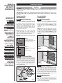
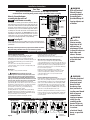
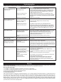
Tools Required:
Phillips Screwdriver
Straight Screwdriver
Wire Strippers
Utility Knife
4 11/2“ Wood Screws
3 Insulated Wire Connectors
1 Strain Relief Connector
The Com-Pak Plus
TM
OWNER’S GUIDE
Side
Features & Benefits
The Com-Pak Plus
Model C
Grill
Front
Wall Can
Side
Bottom
30,48
29,21
17,46
25,4
4,13 3,81
8,26
3,17
8,26
10,16
22,86
The Com-Pak Twin Plus
Model CT
Grill
Front
Side
Wall Can
Side
30,48 29,21
8,26
41,27
36,83
10,16
8,26
■ Primary and Secondary Thermal
Safeguards
• Commercial grade high temperature
manual reset with 25 amp rating at
240 volt
• Over temperature one-time thermal
device
■ Nichrome element wrapped around
mica insulators for durability
■ Powder coat paint process eliminates
sharp cutting edges
■ Two year extended warranty
■ Wall can designed for ease of
installation
■ Factory tested
■ Made in the U.S.A.
Models:
The Com-Pak Plus
C021
*C021T C152
*C152T
C051
*C051T C202
*C202T
C052
*C052T C208
*C208T
C072
*C072T C101
*C101T
C102
*C102T C151
*C151T
C122
*C122T
The Com-Pak Twin Plus
CT252
*CT252T
CT302
*CT302T *Standard built-in
CT402
*CT402T thermostat is single pole
CT408
*CT408T and has no OFF position
General Safety Information
WARNING
Turn the electrical power off at the electrical panel
board (circuit breaker or fuse box) and lock or tag
the panel board door to prevent someone from
turning on power while you are working on the
heater. Failure to do so could result in serious
electrical shock, burns, or possible death.
5. Protect electrical supply from kinks, sharp objects,
oil, grease, hot surfaces or chemicals.
6.
WARNING
DO NOT install the heater in a floor or behind doors.
Overheating or fire may occur.
7.
WARNING
DO NOT install heater in any area where combustible
vapors, gases, liquids, or excessive lint or dust are
present. Fire or explosion may occur.
2. All electrical work and materials must comply with
the National Electric Code (NEC), the Occupational
Safety and Health Act (OSHA), and all state and local
codes.
8.
WARNING
Risk of Electrical Shock. Connect grounding lead to
grounding wire provided. Keep all foreign objects out
of heater.
3. The heater must be grounded to the grounding pigtail
(copper wire) provided in the wall can.
9.
WARNING
Risk of Fire. Heater must be kept clear of all
obstructions: a minimum of 3 feet in front, 6” above
and on both sides. Heaters must be kept clean of lint,
dirt and debris. (See Maintenance Instructions)
1. Read all information labels. Verify that the electrical
supply wires are the same voltage as the heater.
360-693-2505
Fax: 360-694-6939
P.O. Box 1675
4. If you need to install a new circuit or need additional
wiring information, consult a qualified electrician.
Vancouver, WA
98668-1675
Keep for future reference
READ ALL
INSTRUCTIONS
AND SAFETY
INFORMATION
Installation Instructions
Part One
PLACEMENT: Install The Com-Pak Plus (Model C) vertically (recommended) or horizontally. Model C may be
installed in the ceiling (for models up to 1500W maximum). The Com-Pak Twin Plus (Model CT) must be
installed vertically.
THERMOSTAT: A thermostat is required for models without a built-in thermostat. A Cadet Electronic
Thermostat (T4700 or T4800) or Cadet Dual Diaphragm Thermostat (T4398) is recommended for ultimate control
and comfort.
IMPORTANT!
It is extremely
important you
verify that the
electrical supply
wires are the same
voltage as the
heater (i.e. 120 volt
heater to 120 volt
power supply and
240 volt heater to
240 volt power
supply). If
replacing an
existing heater,
check the labels of
the old heater and
replace using the
same voltage.
Hooking a 240 volt
heater to a 120 volt
power supply will
drastically reduce
the heater's output.
Hooking a 120 volt
heater to a 240 volt
power supply will
destroy the heater.
Connecting your
heater to an
incompatible
power supply will
void the warranty.
How do I install in
an existing wall?
How do I install for
new construction?
STEP 1
Mount The Wall Can
STEP 1
The C Series REQUIRES a minimum distance of 6"
from adjacent surfaces and 0" from the floor and
the CT Series requires a minimum distance of 41/2"
from adjacent surfaces and 0" from the floor.
However, Cadet RECOMMENDS 12" from all
adjacent surfaces and 12" above the floor for
longer and cleaner performance. Heaters must be
spaced at least 3 feet apart.
Model C: Secure the wall can to the stud with 2
screws (See Figures 1 & 2). As an option, the
rubber shim provided may be attached to side of
wall can to square the wall can to the stud.
Cut Hole In Wall
Model C: Cut a hole 8" wide by 101/4" high next to
wall stud. The C Series REQUIRES a minimum
distance of 6" from adjacent surfaces and 0" from
the floor. However, Cadet RECOMMENDS 12" from
all adjacent surfaces and 12" from the floor (See
Figure 4).
Model CT: Cut a hole 143/4" wide by 101/4" high next
to wall stud. The CT Series REQUIRES a minimum
distance of 41/2" from adjacent surfaces and 0" from
the floor. However, Cadet RECOMMENDS 12" from
all adjacent surfaces and 12" from the floor (See
Figure 5).
Model CT: Secure the wall can to studs on both
sides with 4 screws.
Figure 1
Face of wall can must
extend 1/2" from face of stud
to allow for sheetrock.
Figure 2
Attach wall can to stud with
screws.
(Model C shown)
STEP 2
Figure 4
Model C
Connect Supply Wires
Route supply wire from circuit breaker to thermostat to heater. For models with built-in thermostat,
route supply wire from circuit breaker to heater.
Remove a knockout and attach the supply wire
with a strain relief connector leaving 10" wire lead
for later use. Connect supply ground wire to
grounding pigtail in wall can (See Figure 3).
Proceed to PART TWO.
Figure 5
Model CT
STEP 2
Connect Supply Wires
Route supply wire from circuit breaker to thermostat to heater. For models with built-in thermostat,
route supply wire from circuit breaker to heater.
Remove a knockout and attach the supply wire with
a strain relief connector leaving 10" wire lead for
later use (See Figure 3). Connect supply ground
wire to grounding pigtail in wall can.
STEP 3
Figure 3
Mount Wall Can
Insert wall can into opening. Keeping wall can flush
with wall, secure model C to wall stud with 2
screws and model CT to both wall studs with 4
screws. Proceed to PART TWO.
Installation Instructions
Part Two
WARNING
Risk of Electrical
Shock. Connect
grounding lead to
grounding wire
provided. Keep all
foreign objects out
of heater.
After you have followed all instructions in PART ONE for either new
construction or an existing wall, you are ready to install the heater assembly.
How do I insert the heater
assembly into the wall can?
STEP 1
Install heater assembly
Turn heater assembly upside-down (element down)
with motor facing you. Connect the supply wires to the
heater wires with connectors (See Figure 6). Now rotate
the heater so the element and fan are facing you (with
the element ‘up’). Insert the bottom edge of the heater
assembly into the half round slots in the bottom lip of
the wall can (See Figure 7). [IMPORTANT: Push wires
into bottom of wall can during insertion. Be sure that
supply wires are not caught between motor and wall
can, attach assembly at top with screw provided.]
STEP 2
Figure 6
WARNING
Risk of Fire.
Heater must be
kept clear of all
obstructions: a
minimum of 3 feet
in front; 6 inches on
both sides and
above. Heaters
must be kept clean
of lint, dirt and
debris.
Install grill
Secure grill with the screws provided. If you have a built-in thermostat
model, slide thermostat knob onto shaft. Turn power on at the electrical
panel board.
Warranty is void if any material is sprayed on the element or blower.
Use paint mask provided if walls are to be textured or painted.
Figure 7
Operation & Maintenance
How to operate your heater
1. Once installation is complete and power has been
restored, turn the thermostat knob fully clockwise.
2. When the room reaches your comfort level, turn the
thermostat knob counterclockwise until the heater turns off.
The heater will automatically cycle around this preset
temperature.
3. To reduce the room temperature, turn the knob
counterclockwise. To increase the room temperature, turn
the knob clockwise.
Maintenance
As needed, or every six months minimum.
1.)
WARNING! Before removing grill, turn the
electrical power off at the electrical panel board (circuit
breaker or fuse box). Lock or tag the panel board door to
prevent someone from accidentally turning the power on
while you are working on the heater. Failure to do so could
result in serious electrical shock, burns, or possible death.
2.) Turn the heater thermostat all the way up and wait
approximately 30 seconds (120 seconds for some electronic
thermostats). If the heater turns on, you have turned off the
wrong circuit breaker at the electrical panel board.
3.) If heater does not turn on, proceed with next step.
4.) Remove screws and take off grill.
5.) Wash grill with hot soapy water and dry immediately.
6.) While holding fan (to avoid damage or bending), use a
hair dryer or vacuum on blow cycle to blow debris through
T
the top element (DoT not touch element).
7.) Vacuum fan area without touching the elements.
8.) Replace grill and secure with screws.
9.) Turn thermostat to desired setting.
10.) Turn power back on at the electrical panel board.
About the Heater Temperature-Limiting Controls
The heater is protected by two temperature-limiting
controls (for Model CT, four controls are used). The first is a
high temperature manual reset switch, designed to open the
heater circuit when excessive operating temperatures are
detected. The problem must be assessed and the limit must
be reset to resume operation.
Further protection is provided by a secondary overtemperature switch, which will open the heater circuit in
severe over-temperature conditions, or in the event of
component failure. If this occurs, the heater must be
repaired or replaced.
Resetting the Manual-Reset Limit Control
If the manual-reset limit control has opened the heater circuit
due to excessive operating temperatures, the heater will not
work until the limit reset button is pressed. After allowing the
unit to cool for at least 10 minutes and resolving the problem
causing the limit to trip, use a narrow object such as a ballpoint pen to access the reset button through the lower-left
section of the heater grill. Press FIRMLY, and be sure to listen
and feel for a click, indicating it has been reset.
Note that resetting the manual limit control may not restore
heater operation if a severe over-temperature condition has
occurred. See the Troubleshooting Guide on next page for
more information.
Wiring Diagrams
The Com-Pak Plus
The Com-Pak Plus
The Com-Pak Twin Plus
The Com-Pak Twin Plus
T
G
G
Figure 8
GG
T
G
G
G
G
G
T
= Ground
= Thermostat
WARNING
Turn the electrical
power off at the
electrical panel
board (circuit
breaker or fuse
box) and lock or
tag the panel board
door to prevent
someone from
turning on power
while you are
working on the
heater. Failure to
do so could result
in serious
electrical shock,
burns, or possible
death.
Troubleshooting Chart
CONSULT LOCAL ELECTRICAL CODES TO DETERMINE WHAT WORK MUST BE PERFORMED BY QUALIFIED ELECTRICAL SERVICE PERSONNEL.
Symptom
Breaker trips immediately upon
energizing heater.
Problem
Solution
1.Incorrect supply voltage.
2.Overloaded circuit.
1. Verify that supply voltage matches the heater rating.
2. The total amperage of all heaters on a branch circuit must not be
more than 80% of the amperage rating of the circuit breaker and
supply wire ratings. Use a lower wattage heater, or reduce the
number of heaters on the circuit.
3. Shorted supply or heater wires may be accompanied by severe
sparking. Inspect all supply and heater wiring insulation for damage.
Do not reset the circuit breaker until all electrical shorts have been
repaired.
4. Replace the circuit breaker.
3.A short circuit exists in the
supply or heater wiring.
4.Defective circuit breaker.
Heater fan operates, but does
not discharge warm air.
Heater will not shut off.
1.Insufficient element temperature. 1. Allow a few moments for element to reach operating temperature.
2.Incorrect supply voltage.
3.Element has failed.
2. Verify that supply voltage matches the heater rating.
3. Replace element.
4.(Model CT only) One of the
heater units must be reset.
4. CT models have two heating units with independent overtemperature controls. One of the high-temperature reset switches
may trip and cut power to one of the heating units, while the other
remains running, resulting in only half output. Reset the heater unit
that is not operating (see "Operation & Maintenance" section for
instructions).
1.Heat loss from room is greater
than heater capacity.
2.Defective thermostat.
1. Close doors and windows. Provide additional insulation, or install a
higher-wattage heater or multiple heaters if necessary.
2. Adjust thermostat to its lowest setting. If heater continues to run
(allow a few moments for the thermostat to respond to the
adjustment), replace thermostat.
3. Refer to thermostat documentation and correct wiring.
3.Thermostat wired incorrectly to
heater.
Heater discharges smoke or
emits a burnt odor.
1.Dust, lint or other matter has
accumulated inside heater.
1. Clean heater (see "Operation & Maintenance" section for
instructions).
Element heats for a moment
without the fan turning, then
immediately stops heating.
1.Defective motor or internal
connection.
2.Fan or motor jammed.
1. Heater or fan motor requires replacement.
Heater does not run.
1.Thermostat set too low.
2. Remove obstruction and press heater reset button (after allowing the
unit to cool). Test heater operation--if reset button has been pressed
(be sure to listen and feel for a click indicating it has been reset), but
heater does not run, heater requires replacement.
1. Adjust thermostat to a higher temperature until heater operates (see
Problem #6 if the problem persists).
2.Heater has tripped the high2. Press the heater reset button (see "Operation & Maintenance"
temperature reset switch.
section for instructions).
3.Heater has tripped the secondary 3. A severe over-temperature condition has occurred. Repair or replace
over-temperature switch.
heater.
4.Power not on at the circuit
4. Turn on the correct circuit breaker in the main panel.
breaker.
5.Broken or poorly connected
5. Turn off power at circuit breaker. Check supply wire continuity and
wire(s) to heater.
proper connection to heater wires.
6.Defective thermostat.
6. Turn off power at circuit breaker. Jumper across thermostat
terminals. Turn on main circuit breaker. If heater operates,
thermostat is defective and should be replaced. Remove jumper
before operating heater.
Warranty
LIMITED TWO-YEAR WARRANTY: Cadet Manufacturing Co. will repair or replace, any Cadet Com-Pak Plus (C), and/or Com-Pak Twin Plus (CT)
element or motor found to be defective or malfunctioning from first date of purchase through the second year.
These warranties do not apply:
1. To conditions resulting from (a) improper installation, or (b) incorrect supply voltage.
2. To conditions resulting from improper maintenance, misuse, abuse, accident or alteration.
3. To service calls or labor involved in replacing defective part.
4. If the date of manufacture cannot be determined.
5. To freight damaged products.
Cadet shall not be liable for commercial consequential damages such as property damage and incidental expenses resulting from breach of
these written warranties or any implied warranty. These warranties give you specific legal rights, and you may also have other rights which vary
from state to state. Cadet neither assumes, nor authorizes anyone to assume for it, any other obligation or liability in connection with these
electric heaters or any part of such heaters. If the product warranted should become defective during the warranty period, contact Cadet
Manufacturing Co. for instructions on how to have the repair or replacement processed. Products returned without authorization will be
refused. To prolong the life of your heater, it is necessary to follow the maintenance guidelines included with each heater. Failure to maintain
your heater will result in the warranty being voided.