1
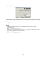
INSTRUCTION MANUAL
FOR
MODEL S-4800
FIELD EMISSION
SCANNING ELECTRON MICROSCOPE
Please read through this manual carefully
before using the instrument.
• Before using the instrument, read the safety
instructions and precautions carefully.
• Keep this manual in a safe place nearby so it
can be referred to whenever needed.
Copyright © Hitachi High-Technologies Corporation. 2002.
All rights reserved.
Printed in Japan.
Part No. 539-8050
NOTICE:
1.
2.
3.
4.
Information contained in this document is subject to
change without notice for improvement.
This manual is copyrighted by Hitachi High-Technologies
Corporation with all rights reserved.
No part of this manual may be reproduced, transmitted
or disclosed to a third party in any form or by any means
without the express written permission of Hitachi
High-Technologies Corporation.
Hitachi High-Technologies Corporation assumes no
liability for any direct, indirect, or consequential damages
arising from use not described in this manual.
Utmost care must be exercised when using the
instrument.
This document does not provide any warranty or
permission for industrial properties or any rights to grant
license lawfully and without infringement.
FOREWORD
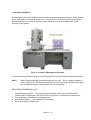
APPLICATION
• The S-4800 SEM utilizes electron beam accelerated at 500 V to 30 kV.
The instrument is designed mainly for observation and evaluation of
specimens prepared for observation using SEM.
• Note that Hitachi High-Technologies Corporation will not be responsible
for injury or damage caused by usage of the instrument in a manner not
described in this manual.
CAUTION
The electron microscope need not conform to the “Radiation Hazard
Preventive Laws” or “Ionizing Radiation Hazard Preventive Regulations”
currently in effect throughout the world, unlike the instruments
designed to produce x-rays.
The suggestion made by the ICRP (International Committee on Radiation
Hazard Prevention), however, clearly defines that the electron
microscope, like the home television set, will potentially produce a certain
amount of x-rays as an undesirable byproduct. From a safety viewpoint,
therefore, it is essential to operate the instrument carefully taking into
account the following fundamental precautions.
(1) Use the instrument within the application range specified in the
catalog or instruction manual.
(2) Do not operate the instrument with covers or doors removed, nor use
alternatives for these components.
(3) Do not apply modifications which may possibly result in deactivation
of the built-in safety devices.
CAUTION
Viewing the screen of the computer monitor and/or operating the computer
keyboard for prolonged, uninterrupted periods of time may result in fatigue
or other problems such as eye strain or repetitive motion injuries.
Therefore, Hitachi High-Technologies Corporation recommends that the
user carefully consider these potential risks when establishing guidelines
for proper use of this instrument in their workplace.
FOREWORD - 1
Before using the equipment, read this instruction manual and pertinent instruction manuals of
relevant accessories to assure proper operation of the equipment.
Scope of Instruction Manual
This instruction manual comprises the following:
1.
2.
3.
4.
5.
6.
Installation (Requirements and Items to be Prepared by User)
Function (Description of Controls)
Operation (Viewing Images, Saving Data, and Taking Photographs)
Maintenance (Procedures, Troubleshooting, and Action on Power Failure)
Replacement Parts
Accessory Operation
This instruction manual describes the operation, maintenance, and specific precautions pertinent
to daily operation on the model S-4800 scanning electron microscope.
First, read and get familiar with the safety precautions described in the opening pages and
General Safety Guidelines.
FOREWORD - 2
GUARANTEE
Period of Guarantee
The charge-free guarantee period is one year from the date of installation.
Details of Guarantee
(a)
(b)
(c)
(d)
The instrument will be repaired free of charge if it malfunctions due to a defect in
manufacture within the charge-free guarantee period.
Note that a substitute part may be used for repair, or replacement with an equivalent
product may be made instead of repair.
Such system components as a personal computer and printer which are frequently
modified for improvement may not be available in original versions at the time of
replacement.
Maintenance procedures are provided to allow system operation for 10 years after its
delivery. During this period, the maintenance of units or parts having a rather short
product cycle such as personal computer and printer may entail the purchase of
substitute parts because of limits on the repair period of the former, for which we
request your understanding. Even when more than 10 years have elapsed after
delivery, maintenance will basically be provided as long as the relevant units and parts
are available.
Exclusions from Guarantee
The guarantee will not be valid for the following failures and/or cases even during the
charge-free guarantee period.
(a) Failure due to use in improperly installed condition.
(b) Failure due to power supply voltage/frequency other than specified by Hitachi
High-Technologies Corporation or due to power failure.
(c) Corrosion or deterioration of the tubing due to impurities contained in gas, air or cooling
water supplied by the customer.
(d) Corrosion of electric circuits or deterioration of optical elements due to corrosive gases
or much dust contained in the atmosphere.
(e) Failure due to disassembly, modification, parts replacement, or relocation not approved
by Hitachi High-Technologies Corporation.
(f) Consumables and parts having a limited period of guarantee.
(g) Failure attributable to use of non-guaranteed parts (parts not described in the
instruction manual).
(h) Failure due to acts of God, including fire, earthquake, storm, flood, lightning, social
disturbance, riot, crime, insurrection, war (declared or undeclared), radioactive
pollution, contamination with harmful substance, etc.
FOREWORD - 3
GUARANTEE
(i)
Failure of instrument or damage of basic software, application software or other data
due to a computer virus.
(j) Failure of the PC used with the instrument or damage to basic software, application
software and/or data because of momentary voltage drop caused by lightning or power
interruption.
(k) Failure of the PC used with the instrument or damage to basic software, application
software and/or data caused by turning off the PC main power without taking the
normal termination procedure.
Limitations on Guarantee
HITACHI HIGH-TECHNOLOGIES CORPORATION MAKES NO GUARANTEES, EITHER
EXPRESS OR IMPLIED, EXCEPT AS PROVIDED HEREIN, INCLUDING WITHOUT
LIMITATION THEREOF, GUARANTEES AS TO MARKETABILITY, MERCHANTABILITY,
FOR A PARTICULAR PURPOSE OR USE, OR AGAINST INFRINGEMENT OF ANY
PATENT. IN NO EVENT SHALL HITACHI HIGH-TECHNOLOGIES CORPORATION BE
LIABLE FOR ANY DIRECT, INCIDENTAL OR CONSEQUENTIAL DAMAGES OF ANY
NATURE, OR LOSSES OR EXPENSES RESULTING FROM ANY DEFECTIVE PRODUCT
OR THE USE OF ANY PRODUCT. NO ORAL OR WRITTEN INFORMATION OR
ADVICE GIVEN BY HITACHI HIGH-TECHNOLOGIES CORPORATION, ITS DEALERS,
DISTRIBUTORS, AGENTS OR EMPLOYEES SHALL CREATE A GUARANTEE OR IN
ANY WAY INCREASE THE SCOPE OF THIS GUARANTEE.
FOREWORD - 4
INSTALLATION AND AFTER-SALES SERVICE
Installation
• Installation at delivery will be carried out by Hitachi High-Technologies Corporation
installation engineers.
• Before installation, refer to section 1 and prepare the necessary utilities.
• Installation at another place after delivery will be provided at charge. Consult your
nearest Hitachi High-Technologies Corporation service representative for details.
After-sales Service
• For after-sales service of the instrument, contact the Hitachi High-Technologies
Corporation sales or service representative in charge.
• For service after the guarantee period, consult Hitachi High-Technologies Corporation with
regard to a maintenance and inspection service contract.
CAUTION ON DISPOSAL OF INSTRUMENT
Although at present the instrument does not use materials that will directly harm the
environment, changes are apt to be made in relevant laws and/or regulations, so be sure to
consult a qualified specialist when planning to dispose of the instrument.
FOREWORD - 5
Available Training Programs
Hitachi High-Technologies Corporation offers various kinds of training programs at its own
facilities or at the user’s site and facilities to ensure proper and safe operations of the equipment
to its full performance.
Please contact your sales representative about the details of the training programs and
application to them. Applicants will be charged.
Handling of Chemicals
(1)
(2)
The user is responsible for proper handling and disposal of chemicals used for cleaning of
the equipment in accordance with applicable regulations.
Follow the supplier’s instructions on handling, storage, and disposal of chemicals.
Instruction Manual
(1)
(2)
(3)
This instruction manual and those instruction manuals for relevant accessories may be
revised for improvement without prior notice.
Hitachi High-Technologies Corporation has the copyright of this instruction manual.
Reproducing or copying of part or all of this instruction manual is not allowed without our
written permission.
FOREWORD - 6
SAFETY SUMMARY
General Safety Guidelines
Before operating the machine, read the following instructions carefully:
•
Follow all the operating procedures provided in this manual.
•
Installation and maintenance must be entrusted to personnel who have received training
at and are authorized by Hitachi High-Technologies Corporation.
•
Pay special attention to and follow all the hazard warnings on the machine and in the
manual. Failure to do so can cause injury to yourself or damage to the machine.
•
The hazard warnings which appear on the warning labels on the machine or in the manual
have one of the following alert headings consisting of an alert symbol and a signal word,
DANGER, WARNING, or CAUTION.
DANGER
: Indicates an imminently hazardous situation which, if not
avoided, will result in death or serious injury.
WARNING
: Indicates a potentially hazardous situation which, if not avoided,
can result in death or serious injury
CAUTION
: Indicates a hazardous situation which, if not avoided, will or can
result in minor or moderate injury, or serious damage of
product.
: The alert symbol shown at left precedes every signal word for
hazard warnings, and appears in safety related descriptions in
the manual.
CAUTION
: Indicates instructions for preventing possible damage to the
instrument.
NOTICE
: Indicates information and descriptions for ensuring correct
usage.
•
Do not perform any operation or action in any way other than as provided in this manual.
When in doubt, call the designated field engineer.
•
Keep in mind that the hazard warnings in this manual or on the machine cannot cover
every possible case, as it is impossible to predict and evaluate all circumstances
beforehand. Be alert and use your common sense.
SAFETY - 1
SAFETY SUMMARY(cont’d)
•
Installation at delivery, maintenance and/or relocation must be carried out under the
supervision of Hitachi-approved specialists.
•
The customer is responsible for proper ventilation of the room when using chemicals.
Inadequate ventilation could cause a health hazard.
•
Maintenance up to 4.4 in section 4 must be entrusted to the service engineers (of Hitachi
Instrument Service). The user should not carry out these procedures.
•
Do not carry out modification of the instrument, parts replacement, use non-specified
parts, nor detach safety mechanisms since this could be hazardous.
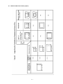
Locations of Warning Labels on the equipment are illustrated on the next pages.
Maintenance of Warning Labels
Contact your nearest Hitachi High-Technologies Corporation service representative for
maintenance of deteriorated or damaged warning labels.
Locations of Warning Labels on the equipment are illustrated on the next pages.
SEMI S2 modification including ANSI style labels is provided as option. Refer to fig S-1
and S-2 for standard version and S-3 and S-4 for ANSI style labels.
SAFETY - 2
Electrical Hazard
Electrical hazards exist due to the following:
Electron Gun
: 0.5 to 30 kV DC
Ion Pump
: 5 kV DC
Photomultiplier
: 1 kV DC
Scintillator of secondary electron detector : 10 kV DC
Electrode 1
: 50 V DC
Electrode 2
: 200 V (Max) DC
Electrode 3
: 100 V (Max) DC
ExB
: 30 V (Max)DC
Penning gauge
: 3 kV
Photo CRT
: 10 kV DC
An enclosure is provided for each high voltage power supply sub-unit. These enclosures are
fixed by screws and electrically connected to the protective grounding, so electrical hazards by
direct contact are prevented.
At the high voltage power supply sub-units, warning labels are attached to prevent hazards
during maintenance. The maintenance should be carried out only by the service personnel
specified and trained by the manufacturer.
The operator should not open the enclosure of the high voltage power supply sub-units in the
main unit, display unit or ion pump power supply unit.
• If you touch a terminal board, you may receive an electric shock.
• If you touch a high-voltage section also, you may receive an electric shock.
SAFETY - 3
High Temperature Hazard
Baking the electron gun part is carried out about once per 6 months to keep high vacuum inside
the part. When baking, the surface of the gun housing and ion pumps reaches around 250 °C.
The electron gun part is surrounded by a metal guard to prevent high temperature hazard caused
by direct contact. However, the temperature of the upper stage surface rises up to
100 °C and the temperature of the side cover surface also rises up to 75 °C. The maintenance
work of baking should be carried out by personnel trained by the manufacturer.
The operator should not touch the covers when the electron gun and ion pumps are heated up to
about 250 °C in order to keep the electron gun in ultra high vacuum. Touching these sections
would result in burns.
Note that the above heated parts are still hot even after stopping heating. Cooling down to close
to room temperature needs about 6 hours.
Magnetic Field Hazard
The ion pumps are constructed with permanent magnets. There is a fringing magnetic field of
about 10 mT at the ion pump surface and about 1 mT at the outside of the ion pump cover.
•
•
Any person who carries a pacemaker embedded is not allowed to approach the ion-pump.
Do not bring near the ion pump wristwatches and magnetic cards that are susceptible to
magnetic fields.
SAFETY - 4
Laser light Hazard
The CD-ROM or CD R/W drive in the personal computer provides with a laser device.
Personal Computer with a laser device complies with safety standards, including International
Electrotechnical Commission (IEC) 825.
With specific regard to the laser, the equipment complies with laser product performance
standards set by US government agencies for a Class 1 laser product.
The product does not emit hazardous light; the beam is totally enclosed during all modes of
customer operation and maintenance.
Therefore, be sure to observe the following warnings when operating a product equipped with a
laser device.
・ Do not try to open the unit enclosure. There are no user-serviceable components inside.
・ Do not operate controls, make adjustments, or perform procedures to the laser device other
than those specified herein.
・ Allow only Service persons to repair the unit.
Laser Information
Laser Type
Wave Length
Divergence Angle
Output Power
Polarization
Numerical Aperture
Semiconductor GaAlAs
780 nm +/- 35 nm
53.5 degrees +/- 0.5 degrees
Less than 0.2 mW or 10,869 W m-2 sr-1
Circular 0.25
0.45 inches +/- 0.04 inche
SAFETY - 5
Fig S-1 Warning labels on the Main unit (standard version)
SAFETY - 6
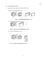
Fig S-2 Warning labels on the Display unit (standard version)
SAFETY - 7
Pinch
(NOTICE : (Labels with(S2) are put to SEMI-S2 guideline conforming version)
Fig S-3 Warning labels on the Main unit (ANSI style labels)
SAFETY - 8
(NOTICE : (Labels with(S2) are put to SEMI-S2 guideline conforming version)
Fig S-3 Warning labels on the Display unit (ANSI style labels)
SAFETY - 9
WARNING
Beware of
electric shock
•
Voltages up to 100 V AC and 30 kV DC are used inside this
instrument. Do not touch inside or you may receive an electric shock.
•
Do not remove the covers of column unit, control unit or power unit
and do not touch internal parts or circuits while the instrument power
is turned on. There is a hazard of fatal or serious injury due to
electric shock.
•
Avoid removing the covers of the instrument. If they must be
removed, make sure to first turn off all power to the instrument.
Electron Gun / Ion pump Baking
•
Beware of high
temperature
The electron gun and ion pump are heated to about 250°C in order to
keep the electron gun in a high vacuum. Touching these sections
would result in burns.
Rotary Pump
•
The temperature of the oil rotary pump rises up to about 70°C, while it
is operating. Touching the pump may also result in burns.
Liquid Nitrogen
•
When you replenish liquid nitrogen in the cold-trap of DP and the
anti-contamination trap, be sure to wear eye-protection glasses and
protective gloves to keep liquid nitrogen from splashing on the eyes or
the skin.
•
Anyone working on the electrical part of the system should follow the
correct lock-out tag-out procedures for that location.
•
The user should prepare a mains switch box on which the lock-out
and the tag-out procedures are provided.
•
Electrical hazards can occur if lock-out tag-out procedures are not
followed.
•
The ion-pump produces magnetic fields. There are fringing magnetic
fields of about 100 Gauss from the ion-pump and 10 Gauss at the
outside of the ion-pump cover.
Beware of low
temperature
Any person who has a pacemaker embedded is not allowed to
approach the ion-pump.
Do not bring near to the ion-pump wristwatches and magnetic cards
that are susceptible to magnetic fields.
Magnetic Fields
SAFETY - 10
WARNING (cont’d)
The CD-ROM or CD R/W drive in the personal computer provides with a
laser device.
Laser Light
Be sure to observe the following warnings when operating a product
equipped with a laser device.
・ Do not try to open the unit enclosure. There are no user-serviceable
components inside.
・ Do not operate controls, make adjustments, or perform procedures to
the laser device other than those specified herein.
・ Allow only Service persons to repair the unit.
SAFETY - 11
Other Relevant Precautions
• Water Leakage Detection
A water-leakage detector is not provided with this equipment. Water leakage may be
caused by corrosion and cracks along the water flow system developed by changes in
cooling-water quality and pressure. If a cooling-water circulating system is not installed,
you should install a water-supply kit; the water-supply kit is provided with a pressurereducing valve and a water-leakage sensor, preventing an accident of water pooling.
• Third Party’s Industrial or Proprietary Rights
Hitachi shall not be responsible for a third party’s claim regarding infringement of any
patent rights or industrial properties with respect either to products manufactured through
the use of equipment supplied by Hitachi or its related companies or to applications of the
Hitachi equipment.
• Cooling Water
(a) You can use city water of which chlorine concentration is less than 0.5 ppm for
cooling water. If the chlorine concentration is higher, use a cooling-water circulating
system to prevent water-leakage due to corrosion of the water flow system.
(b) Necessary flow rate of the cooling water is about 1.5 L/min.
(c) Use a pipe taper-thread to fix the hose to the water faucet.
(d) Be sure to secure the drain hose to the drainage. Loose drain hose can be
responsible for a water pool.
(e) Close the supply valve of the cooling water when not in use.
(f) Soft polyvinyl chloride is used for the supply and drain hoses. These hoses may
become hardened and less flexible after a long period of time. Therefore, regular
replacement is recommended, and be sure to check against water leakage before
use.
(g) If you anticipate the cooling water to freeze in winter, use antifreeze on a coolingwater circulating system.
(h) Cooling water temperature should be controlled so it is not more than 7 °C below the
room temperature. If the temperature difference is greater than this, condensation
may form along the cooling water flow path. And long use under this condition may
cause rusting of the important cooled parts such as objective lens magnetic path and
eventually result in damage to them, whereby the complete set of objective lens will
require replacement. It is thus recommended to use a closed water circulator and
maintain a suitable water temperature.
•
Backup of Important Data
Trouble-free operation cannot be guaranteed for the computer system. You are
recommended to copy important data on the hard disk into floppy disks (FD) or magnetooptical disks (MO) at a regular interval.
SAFETY - 12
Other Relevant Precautions (cont’d)
•
Third Party’s Application Programs
Do not install a third party’s application programs into the PC of the equipment.
Those application programs can be responsible for display of unexpected windows,
adverse effects on the equipment, and interference in the operation of the system
program. Hitachi shall not be liable for the troubles caused by such application
programs.
•
Protection against Computer Viruses
Computer viruses are malicious programs that sneak into the PC to cause misbehavior or
damage to data. And, a program designed to offer protection against and eradicate
computer viruses is called a vaccine program.
Virus infection can be caused by using a floppy disk or other storage medium infected by
a virus. Note also that once the PC is infected by a virus, it may spread to other
computers through storage medium. Therefore, never use a program or storage
medium that is suspected of containing a virus.
If there is a possibility of virus infection, check for a virus using a vaccine program. The
user is requested to prepare a proper vaccine program and carry out virus removal on his
or her own responsibility.
Note, however, that some kinds of vaccine programs may cause incorrect operation of
the S-4800 control program. If a problem occurs after you install a vaccine program,
remove it or execute virus check when the S-4800 program is not running. It is desirable
not to set the vaccine program in the auto start-up group, or to terminate the vaccine
program before starting the S-4800 program.
•
Do Not Change Computer Settings
Do not change the following system settings of your PC. These are set up at the optimum
conditions for operation of the S-4800 SEM before shipping.
(a) Connection to the USB ports
This instrument uses a USB port for communication between the PC and the
internal microprocessor. The USB port number 1 is occupied for the instrument.
Use USB ports on the installed additional USB board for external storage devices,
printer etc. Do not connect these units to the standard USB ports of PC even if
these are open.
(b) Display screen setting
Display properties need to be set at 1280x1024 pixels for the desktop area, true
color (24 bit) mode and 60Hz to 70Hz for the refresh rate. Using other resolution,
faster refresh rate or 256 color mode may cause an abnormal screen display.
(c) Sub programs
This instrument operates using many of dll programs along with control program.
Deletion of files in the Windows directory or change of the registry will cause
troubles. Also do not delete tasks and processes using the task manager.
SAFETY - 13
Other Relevant Precautions (cont’d)
(d)
•
•
•
•
•
•
Power Saving mode
Do not use the Power Saving mode. It will cause trouble for communication
between the PC and internal microprocessor.
(f)
Virtual memory setting
Do not change the virtual memory setting.
OS operation during S-4800 SEM operation
Although the Windows Task Manager can be launched from the Taskbar or using
Ctrl+Alt+Del key operation, if Standby or Halt mode is set or logged-off during S-4800
control program is running, it will not work normally when recovered from such a status.
Close S-4800 control program If setting such mode is necessary.
USB devices
When connecting USB devices such as external storage unit, printer etc., take notice to
followings.
(1) Terminate S-4800 control program when carrying out disk formatting or copying large
volume of image files to MO disk, hard disk or other storage devices using USB port.
(2) By above operation, sometimes the message “USB not connected” will be shown. In
the case, S-4800 control program will not continue normal operation. Terminate Windows
and shut the PC down. Then turn the DISPLAY switch OFF. Turn it on again after waiting
about half a minute.
Power Failure
Instantaneous drop in the line voltage caused by power failure or lightning can be
responsible for malfunction of the PC or damage to system programs, application
programs, or data. An uninterruptible power supply unit is recommended to protect your
system from such instantaneous drop in the line voltage.
Personal Computer (PC)
Do not turn off the PC power independently. If the PC power is turned off during access
to HD or FD, the PC or data and programs stored therein may be damaged.
Be sure to terminate the SEM system software and Windows 2000 software, and then
turn off the PC by means of the DISPLAY switch.
If the PC should become locked, press the Alt, Ctrl and Delete keys simultaneously,
select the process related to locking, then press the Exit button.
Other Precautions for operation
Refer to “Precautions When Using the S-4800 SEM” in the PC-SEM Help shown by
selecting Help menu.
Do not forget other precautions described in the text of the instruction manual.
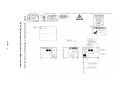
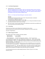
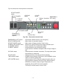
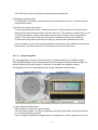
NOTICE:The model S-4800 has two nameplates. The nameplate at the back of the main unit
indicates production serial number, production date, manufacturer name and AC
power input. The nameplate at the back of the display unit idicates rated voltage,
current and frequency of AC power input.
SAFETY - 14
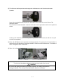
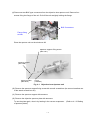
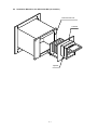
Emergency Off Button
The Emergency Off button (EMO) is a red, mushroom shaped pushbutton switche, that is located
on the Evacuation control panel of Main unit. Its purpose is to shut off all power in the system
when pushed, and it is a non- momentary switch which is never be overridden even during
servicing of the system.
Fig S- 5 Location of Emergency Off button
It is recommended to check the function of Emergency Off circuit during the regular maintenance.
NOTE :
When pushing the EMO, the whole power line is cut off. Since a battery backed up
power supply for the PC is not mounted the PC can not finish the shutdown sequence,
thus possibly causing serious damage to the PC file system.
RECOVER OF EMERGENCY OFF
1.
2.
3.
4.
Check the whole system. If the system has something wrong, call service personnel
(Hitachi High-Technologies Corporation service engineer etc.) and execute maintenance.
Turn all breakers on the back og the display unit.
Unlock EMO switch. (Turn clockwise for unlocking)
Refer to section 4 for starting up.
SAFETY - 15
Main Power Disconnect
Lock out/tag out procedure are very important safety concern.
The purpose of the lock out/tag out procedure is to insure safety while working on electrical and
mechanical equipment. Make sure you get introduced to the person responsible for the
equipment at the site. When you need to power down the system and work on it in that state,
you must lock out/tag out. If the main Disconnect is a knife switch, turn it off and place your pad
lock in the hole provided. Place a tag that is clearly readable with your name and how you can
be reached on it, remember you are the only person that has a key to unlock this Disconnect. If
the main Disconnect is a receptacle type, remove it and place a lockable box cover over it and
tag it, again you keep the only key. If there is no disconnect you should turn off main breaker at
power supply and physically disconnect the power output of the main breaker.
Power Supply and Grounding Connection
This instrument is designed to operate on AC 100 V input power voltage. If other than 100 V
input power must be used, it is required to use the double installation transformer.
Refer to <1.3.1 Power and Ground Wirings> for connection of the transformer.
In this case, using a voltage meter, make sure that the output voltage of the transformer is 100 V.
Connect the instrument to ground based on the standard of your country.
Avoid sharing the ground terminal with other power equipments. Be sure to ground the
instrument independently.
SAFETY - 16
INTERLOCK
Electron Gun
Ion Pump
Other High Voltages
Baking power supply
Unit power supply
Protection for Earthquakes
Gravity location of units
Water-leakage detection
The Gun cable is now interlocked with a momentary switch.
If the cover at the top of the electron gun is removed to
disconnect gun cable, the High Voltage applied to the electron
gun is shut off. This switch can be overridden for service.
However, if the cable is replaced the service override is removed.
The ion pump cover at the back of the electron optical column
has a safety interlock switch. If the cover is removed, the High
Voltage supplied to the ion pumps is shut off and lamps in the
RESET switches for ion pumps located on the evacuation control
panel will go off. For service the switches can be overridden,
but as soon as the ion pump cover is put again, the service
override is removed.
High voltage power supply for photo multipliers and electrodes
are placed inside of a box located at the behind of the specimen
chamber. The cover of the box has a safety interlock switch. If
the cover is removed, the High Voltage supplied to the photo
multipliers and electrodes is shut off. For service the switches
can be overridden, but as soon as the cover is put again, the
interlock is functional.
Baking heater power supply connectors are placed at the right
side of the ion pumps cover. To connect heater connectors, the
box cover of the connector must be removed. The box cover of
the connector has a safety interlock switch. The baking power is
shut off when the cover is removed. After connecting connectors,
put the cover again. The baking power then becomes applicable.
Four side covers of the Main unit have safety interlock switches
one for each. If one of the side covers is removed, AC power
supply for the Main unit (for evacuation system, ion pump power
supply and stage controller) will be shut off. The switches can be
overridden for service. However, if the covers are put again, the
service override is removed.
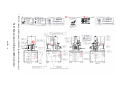
The interlock location is shown in fig S-6
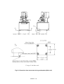
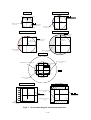
It is recommended that the protection for movement of Main unit
and Display unit during earthquakes is to be provided by user as
shown in figures S-7 and S-8.
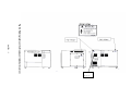
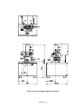
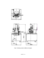
The gravity location of Main and Display unit are shown in fig S9 through S-11.
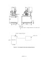
It is recommended that the water–leakage detector is to be
provided by user. Figure S-12 shows an example of the water–
leakage detector.
SAFETY - 17
Fig S- 6 Location of safety interlock
SAFETY - 18
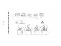
Fig S- 7 Protection from movement during earthquakes (Display unit)
SAFETY - 19
Fig S- 8 Protection from movement during earthquakes (Main unit)
SAFETY - 20
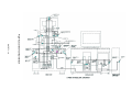
Fig S- 9 Gravity location of Main unit (Type1)
SAFETY - 21
Fig S- 10 Gravity location of Main unit (Type2)
SAFETY - 22
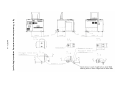
Fig S- 11 Gravity location of Display unit
(Not include monitor display)
SAFETY - 23
Fig S- 12
An example of the water-leakage detector
SAFETY - 24
PRECAUTIONS ON HANDLING
For the sake of safety, the following points should be taken into consideration.
1.
PRECAUTIONS FOR TRANSPORT
CAUTION
(1)
Do not lift the instrument by holding the table. The strength of table fitting is not sufficient
for bearing the weight of display unit, approximately 200 kg. Should the table be lifted, the
display unit might slip off and crash. Hence, it is recommended to remove the table and
transport the display unit independently when moving the instrument.
(2)
The housing supports should be fitted in place before transport.
2.
PRECAUTIONS FOR POWER CONNECTION
WARNING
(1)
When removing the front, rear and top covers of housing and display unit, turn off the AC
power. The high voltage circuit within the unit constitutes a shock hazard.
(2)
Connect the grounding wire correctly. Otherwise, not only will the instrument fail to
operate normally but there is a shock hazard.
(3)
Avoid touching the connector of high voltage unit and the cable head of high voltage
transformer. The high voltage unit and the high voltage transformer are at voltages as
high as 30 kV, so handling of dangerous parts such as high voltage connector and cable
head should be left to the service engineer.
(4)
Do not touch the areas marked HAZARD. These areas are supplied with high voltage.
(5)
When replacing a fuse, turn off the main switch on the distribution board and make sure
that the AC power supply is cut off. If not the AC power line near the fuse box may cause
shock.
PRECAUTION - 1
CAUTION
(1)
Never touch the electron gun with bare hands in the course of baking and cooling.
High temperature during baking may cause burns.
(2)
When using liquid nitrogen, wear leather gloves and protective glasses. There is danger if
it touches the skin as it can cause low temperature burns. Also, make sure there is
enough ventilation in the room to prevent oxygen deficiency.
(3)
When the anti-contamination trap is filled with liquid nitrogen, do not allow an air leak in the
specimen chamber. This will cause the deterioration of vacuum, leading to frost in the
anti-contamination trap.
(4)
When setting the specimen tilt and the stage Z to minimum, there is a danger of contact
that could scratch the specimen or objective lens. Be sure to use the special level gauge
for setting the specimen and set the specimen height to be not more than 0.5 mm higher
than the level gauge.
(5)
Be careful not to hit your head when checking the specimen chamber because the beam
monitor aperture, secondary electron detector, etc. are sticking out of the top area of the
specimen exchange chamber.
(6)
Do not place objects containing a magnetic powder in the specimen chamber.
The magnetism of the objective lens attracts the powder and it will attach to the magnetic
pole of objective lens separating from the specimen stage. This causes a deterioration of
performance.
(7)
Since a magnetic specimen is strongly attracted by the magnetic field of the objective lens,
secure it tightly to the specimen stage. If it is not tight enough, it may be drawn to the
objective lens and cause problems.
(8)
When the specimen stage is being manually operated, set it so as not to go over the limit in
the Z axis or the Tilt (T) axis adjustments. Exceeding these limits may damage the
specimen or parts of the specimen chamber.
(9)
If the specimen stage is being manually operated, do not operate Z and T axes in the stage
locked condition. This damages the stage lock system and causes deterioration of stage
precision.
(10) The oil rotary pump is a heavy object that weighs 30 kg. Be very careful if it must be lifted
or moved when performing maintenance.
(11) When performing maintenance on the compressor, open the drain valve slowly and drain
the condensed water from the tank gradually. High air pressure inside the tank can cause
dangerous splashing and spraying of the condensate if the drain is opened too quickly.
PRECAUTION - 2
NOTICE
(1)
Allow an interval of at least 20 seconds between turning on or off the EVAC POWER and
DISPLAY POWER switches.
(2)
Replace the oil filter of the oil-sealed rotary pump every six months.
(3)
For the air compressor and oil-sealed rotary pump, perform draining of water, check of oil
level etc. with reference to the check card attached to the instrument.
(4)
Do not press the EMERGENCY switch except in emergencies. Using this switch causes a
complete instrument shutdown that will necessitate a complete instrument restarting.
(5)
When attaching the electron gun cover, make sure the lead wires are not in contact with the
heater.
3.
GENERAL PRECAUTIONS
(1)
Maintenance items other than those described in this manual should be left to the service
engineer.
(2)
Any replacement of the FE (field emission) tip should be performed by a Hitachi
High-Technologies Corporation service representative.
4.
MEASURES FOR EMERGENCY
(1)
Turn off the main switch on the distribution board.
(2)
If water is leaking, close the valve of cooling water to cut off the water supply.
(3)
After taking steps (1) and (2), carry out other suitable measures.
(4)
Inform the service shop.
PRECAUTION - 3
5.
CAUTIONS ON OPERATION
(1)
During operation, occasionally confirm that the ion pumps are in a stable state.
IP-1
2 × 10⁻⁷ Pa or better
IP-2
2 × 10⁻⁶ Pa or better
IP-3
5 × 10⁻⁵ Pa or better
(2)
When emission current varies widely during operation depress the HV OFF switch to cut off
high voltage of the electron gun. Then, set the flashing intensity to ‘2’ or ‘3’, and carry out
flashing.
(3)
When leaving the instrument depress the HV OFF switch.
(4)
Avoid using excessive fixing agent (conductive paste or the like) when setting the specimen
onto the specimen stub.
6.
OTHERS
(1)
Keep the instrument installation room under the following conditions even when the
instrument is not in operation.
Room temperature : 5 to 25 °C
(temperature of diffusion pump cooling water also)
Humidity
: Less than 60%
Evacuation must be performed continuously even when the instrument is not used for a
long time. An uninterruptible power supply must be provided for this purpose.
(2)
The DP drain port should be located at a height of less than 20 cm from the floor.
PRECAUTION - 4
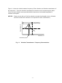
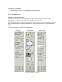
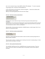
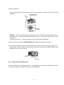
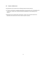
(1)
FLASHING
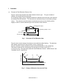
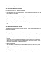
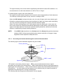
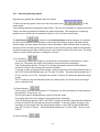
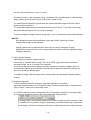
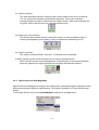
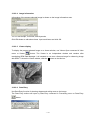
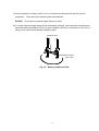
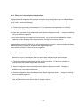
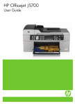
Principle of Field Emission Electron Gun
Figure 1 shows the principle of the field emission electron gun. The gun consists of
cathode, first anode and second anode.
An extracting voltage (Vext) is applied between the cathode and first anode, and electrons
are emitted from the cathode. The electrons are accelerated by an accelerating voltage
(Vacc). The cathode need be cleaned occasionally by turning on the flashing power
supply in order to remove adsorbed gas on the surface of the cathode.
Flashing power supply
Extracting voltage
(Vext)
Cathode
Accelerating voltage(Vacc)
First anode
Second anode
Fig. 1
Principle of Field Emission Gun
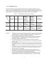
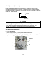
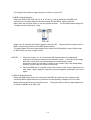
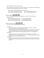
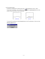
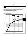
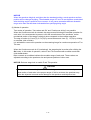
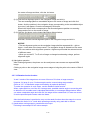
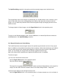
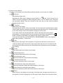
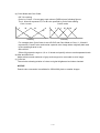
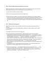
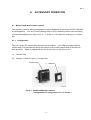
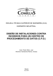
Figure 2 plots a usual change of emission current with time after flashing. The abscissa
and ordinate represent time and emission current, respectively.
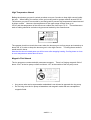
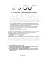
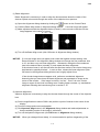
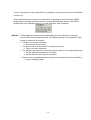
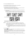
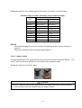
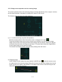
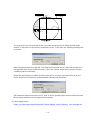
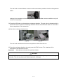
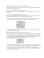
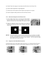
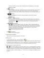
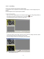
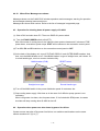
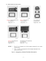
Figure 3 sketches a status transition of gas molecules adsorbed on the cathode tip.
The status (a) through (b) correspond to (a) through (d) on the curve in Fig. 2.
A, B and C in Fig. 2 are generally called an “Initial Reduction Period”, “Stable Period” and
“Unstable Period”, respectively.
(a)
Emission current
7.
(b)
A
(c)
(d)
B
Initial
Stable Period
Reduction Period
C
Unstable Period
Time
Fig. 2
Change of Emission Current with Time
PRECAUTION - 5
Gas Molecules
Cathode Tip
(a)
Fig. 3
A :
B :
C :
(b)
(c)
(d)
Status Transition of Adsorbed Gas Molecules on Cathode Tip
In the initial reduction period, or just after flashing, gas is completely discharged from
the cathode tip. (See (a) of Fig. 3.) As gas molecules are gradually adsorbed onto
the cathode, emission current decreases. In this stage, gas molecules are
desorbed, adsorbed and transferred. So noise (fluctuation of emission current)
occurs. (See (b) of Fig. 3.)
In the stable period approximately one layer of gas molecules is adsorbed onto the
cathode. In this status a stable emission current is usually available. (See (c) of
Fig. 3.) Although noise (fluctuation of emission current) may appear occasionally
due to desorption and adsorption of gas molecules a stable status returns in a
comparatively short time. So record an image after confirming the stable status.
In this period emission current slightly decreases with time.
In the unstable period a large quantity of gas molecules repeat desorption and
adsorption. In consequence emission current fluctuates considerably while
increasing. (See (d) of Fig. 3.)
Images are observed usually in the stable period.
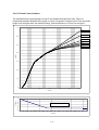
The periods sectioned on the time axis in Fig. 2 vary depending on electron gun vacuum,
residual gas component, cathode/anode cleanliness and emission current value.
With the Model S-4800, they are roughly given as follows.
• Initial reduction period : 30 min to 3 hours
• Stable period
: 2 to 12 hours
When the initial reduction period is half an hour, the stable period lasts 2 to 4 hours, and 4
to 10 hours when the initial reduction period is 1 to 2 hours (approximate values). Even in
the unstable period, flashing cleans the surface of the cathode as shown in Fig. 3 (a) and
emission current changes again as illustrated in Fig. 2, whereby the stable period returns.
(2)
Flashing Practice
The flashing may be practiced in either of the following two fashions:
(a) Carry out flashing once at the start of use.
Then when the emission current becomes unstable after two to eight hours of use
(cumulative time of beam turn-on), perform flashing again.
(b) Carry out flashing once on completion of daily operation. On the next day start
operation without flashing, and perform flashing if the emission current becomes
unstable during use.
PRECAUTION - 6
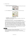
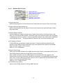
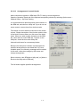
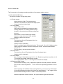
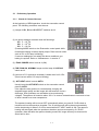
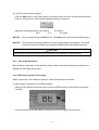
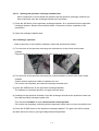
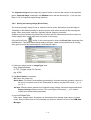
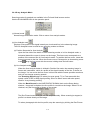
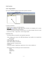
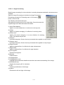
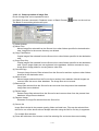
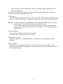
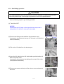
(3)
Flashing Procedure
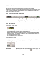
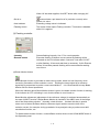
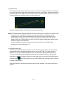
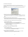
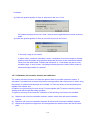
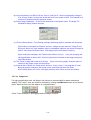
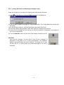
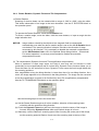
(a) Check and set up intensity of flashing as follows:
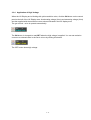
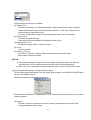
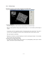
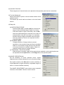
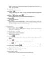
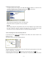
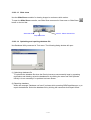
Click the HV display area on the control panel. The HV control dialog window will open.
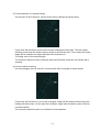
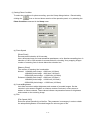
(b) Click the Flashing button on it. The Flashing execution dialog window will open.
Set Intensity to “2” and click Execute button.
The emission current value caused by flashing will be displayed on the Ie part of the
HV Display area about 2 seconds.
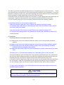
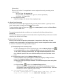
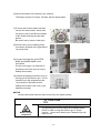
Usually flashing is set at Intensity ‘2’. However when the stable period is short or
extracting voltage (Vext) rises at about 1 hour after pressing HV ON (because a large
quantity of gas molecules are adsorbed on the cathode), set intensity ‘3’. There may be a
case where noise (bright or dark lateral stripes on CRT) appears in the initial reduction
period. But this does not constitute a problem since noise will disappear in the stable
period. Even if noise appears in the stable period, it will be suppressed in a short time.
In this case wait until the stable status returns before recording an image. In the stable
period, emission current slightly decreases. If noise becomes conspicuous during image
observation upon entering the unstable period, press the HV OFF switch, and set intensity
‘2’ for flashing again. Emission current repeats a change as traced in Fig. 2, so image
observation is enabled in the stable period again.
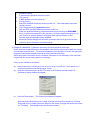
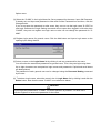
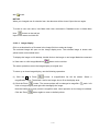
NOTICE
A message will appear when 8 hours of cumulative operation time or 24 hours of total time
have passed after flashing, as a reminder to flash the tip again.
If the tip is not flashed within 30 minutes, the HV will be turned off automatically.
(These time periods can be set at other values if necessary. Contact a service engineer
to change them.)
PRECAUTION - 7
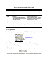
SPECIFICATION
Specifications for Hitachi Model S-4800, Field Emission Scanning Electron Microscope
1.
Resolution:
Accelerating voltage 15 kV
Working distance = 4 mm .............................. 1.0 nm
Accelerating voltage 1 kV
Working distance = 1.5 mm ........................... 2.0 nm
2.
Magnification:
High magnification mode ............................... 100× to 800,000×
Low magnification mode ................................ 30× to 2,000×
3.
Electron Optics:
(1)
Electron gun .......................................... Cold cathode field emission type
(2)
Extracting voltage (Vext) ....................... 0 to 6.5 kV
(3)
Accelerating voltage (Vacc)................... 0.5 to 30 kV (in 100 V steps)
(4)
Lens....................................................... 3-stage electromagnetic lens, reduction type
(5)
Objective lens aperture.......................... Movable aperture (4 openings selectable/
alignable outside column).
Self-cleaning thin aperture
(6)
Astigmatism correction coil
(stigmator) ............................................. Electromagnetic type
(7)
Scanning coil ......................................... 2-stage electromagnetic-deflection type
PRECAUTION - 8
4.
Specimen Stage
Motion
5.
Model S-4800, Type I
Model S-4800, Type II
X Traverse
0 to 50 mm (continuous)
0 to 110 mm (continuous)
Y Traverse
0 to 50 mm (continuous)
0 to 110 mm (continuous)
Z Traverse
1.5 to 30.0 mm (continuous)
1.5 to 40.0 mm (continuous)
Tilt
-5° to +70°
-5° to +70°
Rotation
360° (continuous)
360° (continuous)
Specimen size
Max. 100 mm (diameter)
(airlock type specimen exchange)
Max. 150 mm (diameter)
(airlock type specimen exchange)
Display Unit
(1)
Display type .........................................Flicker- free image on PC monitor
(full scanning speeds)
(2)
Viewing monitor ...................................Type 18.1 LCD (Type 21 Color CRT: Option)
(1280 × 1024 pixels)
(3)
Photo CRT (Option).............................Ultra-high resolution type
(effective field of view 120 × 90 mm)
(4)
Scanning modes..................................Normal scan,
Reduced area scan,
Line scan,
Spot analysis,
Average concentration analysis,
Split/Dual magnification,
(5)
Scanning speeds .................................TV
(640×480 pixels display : 25 / 30 flames/s)
Fast (Full screen display : 25 / 30 flames/s)
Slow (Full screen display :
1/0.9, 4/3.3, 20/16, 40/32, 80/64 s/flame)
(640×480 pixels display :
0.5/0.4, 2/1.7, 10/8, 20/16, 40/32 s/flame)
For Photograph (2560×1920 pixels display :
40/32, 80/64, 160/128, 320/256 s/flame)
Value of (50 Hz)/(60 Hz)
TV : NTSC or PAL signal
PRECAUTION - 9
(6)
Signal processing modes ....................Automatic brightness control,
Gamma control,
Automatic focus,
Automatic stigmator
(7)
Automatic data display ........................Image number, accelerating voltage, magnification,
micron bar, micron value, date/time and working
distance can be printed on the film.
(8)
Data entry ............................................Alphanumeric characters, numbers, and marks can
be written on the image from the keyboard.
(9)
Electrical image shift............................±12 µm (WD = 8 mm)
6.
Evacuation System
(1)
System type.........................................Fully automatic pneumatic-valve system
(2)
Ultimate vacuum levels........................Specimen chamber : 7 × 10⁻⁴ Pa
Electron gun chamber :
IP-1 1 × 10⁻⁷ Pa or better
IP-2 2 × 10⁻⁶ Pa or better
IP-3 7 × 10⁻⁵ Pa or better
(3)
Vacuum pumps....................................Electron optical system : 3 ion pumps
Specimen chamber
: Turbo molecular pump
1 oil rotary pump should be provided by user.
(4)
Compressor .........................................Oil-less type compressor should be provided by user.
7.
Protection Devices
Warning devices ..........................................Power failure, Cooling-water interruption, Inadequate
vacuum
PRECAUTION - 10
INSTALLATION CONDITIONS
1.
Power Requirements
100 V AC (±10%), single phase, 50/60 Hz, 4 kVA
In case to use other voltage than 100V AC, a double insulation transformer should be provided
by user.
Exclusive grounding of less than 100 ohms in ground resistance should be provided by user.
2.
Physical Dimensions
Main unit ............................. S-4800I
840 (W) × 966 (D) × 1620 (H) mm: 583 kg
S-4800II
840 (W) × 966 (D) × 1660 (H) mm: 651 kg
Display unit ...........................................1000 (W) × 960 (D) × 1200 (H) mm: 205 kg
3.
Installation Environment
(1)
Ambient temperature ............... 15 °C to 25 °C (temperature variation 0.5 °C/10 min)
(2)
Relative humidity ..................... Less than 60%, without condensation
(3)
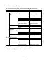
Stray magnetic field
Frequency
Component
Synchronous with
Accelerating Working
Magnification
Power Supply AC
Voltage
Distance
Magnetic Field
(effective value)
Frequency
Component
Asynchronous with Change with Time
(drift)
Power Supply DC
Magnetic Field
Fluctuation
15 kV
4.0 mm
220,000×
290 nT (horizontal)
220 nT (vertical)
320 nT (horizontal)
240 nT (vertical)
600 nT/min (horizontal)
450 nT/min (vertical)
1 kV
1.5 mm
120,000×
150 nT (horizontal)
130 nT (vertical)
170 nT (horizontal)
150 nT (vertical)
310 nT/min (horizontal)
280 nT/min (vertical)
Allowable
value
nT: Nano Tesla
PRECAUTION - 11
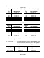
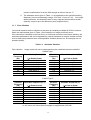
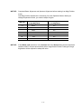
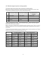
(4)
Floor vibration
S-4800 Type I
Oscillation
Frequency
(Hz)
1.0
1.4
2.0
3.0
4.0
5.0
6.0
10.0
Allowable Amplitude (X, Y)
(µm Peak to Peak)
Less than 7.0
Less than 2.0
Less than 2.0
Less than 4.0
Less than 4.5
Less than 4.5
Less than 4.0
Less than 3.0
Oscillation
Frequency
(Hz)
1.0
2.0
3.0
3.5
4.0
5.0
6.0
10.0
Allowable Amplitude (Z)
(µm Peak to Peak)
Less than 25.0
Less than 14.0
Less than 5.0
Less than 2.9
Less than 1.8
Less than 1.0
Less than 1.1
Less than 1.2
S-4800 Type II
Oscillation
Frequency
(Hz)
1.0
1.5
2.0
2.4
3.0
5.0
6.0
10.0
Allowable Amplitude (X, Y)
(µm Peak to Peak)
Less than 8.0
Less than 3.0
Less than 1.4
Less than 1.4
Less than 3.0
Less than 4.0
Less than 3.5
Less than 3.5
Oscillation
Frequency
(Hz)
1.0
2.0
3.0
4.0
5.0
6.0
7.0
10.0
Allowable Amplitude (Z)
(µm Peak to Peak)
Less than 20.0
Less than 10.0
Less than 5.0
Less than 2.7
Less than 1.8
Less than 1.0
Less than 1.0
Less than 1.0
The allowable amplitude corresponds to an image deviation of less than 0.2 mm on a
micrograph at magnification 220,000×
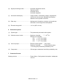
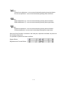
(5)
Acoustic noise .................. The following table shows the relation between allowable noise
level (C characteristic) and frequency at the S-4800 installation
site. The allowable amplitude corresponds to an image
deviation of less than 0.2 mm on a micrograph at magnification
220,000×.
Frequency : f (Hz) Allowable Noise Level(Type I) Allowable Noise Level (Type II)
f≦150
75 dB or less
72 dB or less
150≦f≦800
60 dB or less
60 dB or less
800≦f≦2000
54 dB or less
52 dB or less
PRECAUTION - 12
4.
Water Supply and Drain
(1)
Water flow rate ........................ 1 to 1.5 L/min
(2)
Water pressure ........................ 50 to 100 kPa
(3)
Water temperature................... 10 to 20 °C (temperature variation: less than 0.5 °C/10 min)
(4)
Water supply port .................... One port, with Rc 3/8 taper internal thread.
(If water contains significant deposit or impurities, consult
Hitachi High-Technologies Corporation separately.)
Water drain port....................... One port, more than 20 mm in diameter
(natural drainage type)
(5)
PRECAUTION - 13
MODEL S-4800 FIELD EMISSION
SCANNING ELECTRON MICROSCOPE
Table of Contents
FOREWORD...................................................................................................... FOREWORD-1
Scope of Instruction Manual ....................................................................... FOREWORD-2
GUARANTEE..................................................................................................... FOREWORD-3
INSTALLATION AND AFTER-SALES SERVICE............................................... FOREWORD-5
CAUTION ON DISPOSAL OF INSTRUMENT ................................................... FOREWORD-5
Available Training Programs....................................................................... FOREWORD-6
Handling of Chemicals ................................................................................ FOREWORD-6
Instruction Manual....................................................................................... FOREWORD-6
SAFETY SUMMARY........................................................................................... SAFETY-1
General Safety Guideline............................................................................. SAFETY-1
Electrical Hazard.......................................................................................... SAFETY-3
High Temperature Hazard ........................................................................... SAFETY-4
Magnetic Field Hazard................................................................................. SAFETY-4
Laser light Hazards...................................................................................... SAFETY-5
Warning Labels on the Main Unit (standard version)................................... SAFETY-6
Warning Labels on the Display Unit (standard version)............................... SAFETY-7
Warning Labels on the Main Unit (ANSI style labels) .................................. SAFETY-8
Warning Labels on the Display Unit (ANSI style labels) .............................. SAFETY-9
WARNING.................................................................................................... SAFETY-10
Other Relevant Precautions......................................................................... SAFETY-12
Emergency Off Button.................................................................................. SAFETY-15
Main Power Disconnect ............................................................................... SAFETY-16
Power Supply and Grounding Connection................................................... SAFETY-14
INTERLOCK ....................................................................................................... SAFETY-17
Location of safety interlock .......................................................................... SAFETY-18
Protection from movement during earthquakes (Display unit) ..................... SAFETY-19
Protection from movement during earthquakes (Main unit) ......................... SAFETY-20
Gravity Location of Main unit (Type1) .......................................................... SAFETY-21
Gravity Location of Main unit (Type2) .......................................................... SAFETY-22
Gravity Location of Display unit ................................................................... SAFETY-23
An example of the water-leakage detector .................................................. SAFETY-24
-i-
Table of Contents (Cont’d)
PRECAUTIONS ON HANDLING ...................................................................... PRECAUTION-1
1. Precautions for Transport ................................................................... PRECAUTION-1
2. Precautions for Power Connection ..................................................... PRECAUTION-1
3. General Precautions ........................................................................... PRECAUTION-3
4. Measures for Emergency.................................................................... PRECAUTION-3
5. Cautions on Operation ....................................................................... PRECAUTION-4
6. Others................................................................................................. PRECAUTION-4
7. Flashing.............................................................................................. PRECAUTION-5
SPECIFICATION ............................................................................................. PRECAUTION-8
INSTALLATION CONDITIONS........................................................................ PRECAUTION-11
1.
INSTALLATION ............................................................................................................. 1-1
1.1 Installation Requirements ..................................................................................... 1-1
1.1.1
General ................................................................................................... 1-1
1.1.2
Room Temperature and Humidity........................................................... 1-1
1.1.3
Line Power Requirement ........................................................................ 1-2
1.1.4
Grounding ............................................................................................... 1-2
1.1.5
Water Supply and Drain.......................................................................... 1-2
1.1.6
Stray Magnetic Field ............................................................................... 1-3
1.1.7
Floor Vibration ........................................................................................ 1-4
1.1.8
Power Line Noise and Electric Field Due to Noise ................................. 1-6
1.1.9
Disturbance by Sound Waves ................................................................ 1-7
1.1.10 Site Requirements .................................................................................. 1-7
1.2 Materials or Instruments to be prepared by User ................................................. 1-9
1.3 Wiring ................................................................................................................... 1-9
1.3.1
Power and Ground Wirings..................................................................... 1-10
- ii -
Table of Contents (Cont’d)
2.
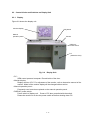
FUNCTIONS .................................................................................................................. 2-1
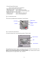
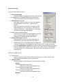
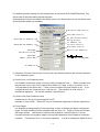
2.1 Control Knobs and Switches on Main Unit ........................................................... 2-2
2.1.1
Main unit (column) .................................................................................. 2-2
2.2 Control Knobs and Switches on Display Unit.......................................................... 2-13
2.2.1
Display .................................................................................................... 2-13
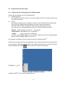
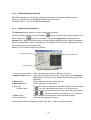
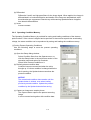
2.3 Graphical User Interface (GUI) ............................................................................. 2-16
2.3.1
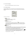
Starting the PC and Logging in the S-4800 Program ............................. 2-16
2.3.2
S-4800 SEM Main Window..................................................................... 2-18
2.3.3
Control arrangement on the window....................................................... 2-19
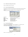
2.3.4
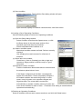
Menu....................................................................................................... 2-21
2.3.5
Control Panel .......................................................................................... 2-26
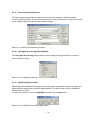
2.3.6
Operation Panel...................................................................................... 2-33
2.3.7
Mouse operation on the scanning image................................................ 2-42
2.3.8
Setup dialog window............................................................................... 2-44
2.3.9
Captured Image Window ........................................................................ 2-51
2.3.10 SEM Data Manager Window .................................................................. 2-52
2.3.11 Alignment Dialog Window....................................................................... 2-52
2.3.12 CD Measurement dialog window (option)............................................... 2-53
2.3.13 Comm Port Setting Dialog Window ........................................................ 2-53
2.3.14 Login Setting Dialog Window.................................................................. 2-53
2.3.15 Oblique Dialog Window .......................................................................... 2-54
2.3.16 Password Setting Dialog Window........................................................... 2-54
2.3.17 Save Image Dialog Window.................................................................... 2-55
2.3.18 Opt Signal Processing Dialog Window ................................................... 2-55
2.3.19 Split/Dual Mag Controller........................................................................ 2-55
2.3.20 Using Short-Cut Keys ............................................................................. 2-56
3.
OPERATION.................................................................................................................. 3-1
3.1 Preliminary Operation ........................................................................................... 3-3
3.1.1
Check of Column Vacuum ...................................................................... 3-3
3.1.2
Flow the cooling water ............................................................................ 3-4
3.1.3
Starting the Display................................................................................. 3-5
3.1.4
Use of Anti-Contamination Trap ............................................................. 3-6
3.2 Specimen Setting and Specimen Exchange......................................................... 3-7
3.2.1
Cautions on Specimen Preparation ........................................................ 3-7
3.2.2
Specimen Preparation for Materials ....................................................... 3-7
3.2.3
Adjustment of Specimen Height ............................................................. 3-8
3.2.4
Specimen Exchange Position ................................................................. 3-8
3.2.5
How to Set Specimen ............................................................................. 3-9
- iii -
Table of Contents (Cont’d)
3.3
3.4
3.5
3.6
3.7
3.8
3.9
Application of High Voltage .................................................................................. 3-12
3.3.1
Condition where the gun high voltage is applicable................................ 3-12
3.3.2
Flashing .................................................................................................. 3-12
3.3.3
Setting of Accelerating Voltage and Emission Current ........................... 3-13
3.3.4
Application of High Voltage..................................................................... 3-14
Optimizing the Electron Beam .............................................................................. 3-15
3.4.1
Selecting a Magnification Mode.............................................................. 3-15
3.4.2
Selecting Electron Optical Column Condition ......................................... 3-15
3.4.3
Column Alignment Operation.................................................................. 3-20
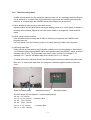
Operation for Image Observation ......................................................................... 3-24
3.5.1
SE detector ............................................................................................. 3-24
3.5.2
Selecting Magnification........................................................................... 3-18
3.5.3
Selecting Scanning Speed...................................................................... 3-29
3.5.4
Image Brightness and Contrast Adjustment ........................................... 3-31
3.5.5
Focus and Astigmatism Correction......................................................... 3-34
3.5.6
Operation of the Specimen Stage (Type I - Manual Stage) .................... 3-37
3.5.7
Operation of the Specimen Stage (Type 2 - 5-Axis Motorized Stage) .... 3-41
Saving and Recording Images.............................................................................. 3-71
3.6.1
Saving and Recording Images................................................................ 3-71
3.6.2
Preparing Images for Recording............................................................. 3-72
3.6.3
Setting Conditions for Image Capturing.................................................. 3-73
3.6.4
Image Capturing ..................................................................................... 3-74
3.6.5
Saving a Scanning Image (Direct Save)................................................. 3-75
3.6.6
Saving Captured Images ........................................................................ 3-76
3.6.7
Taking Photographs (Option).................................................................. 3-76
Using SEM Data Manager .................................................................................... 3-79
At the End of Daily Use......................................................................................... 3-80
3.8.1
Turning High Voltage Off ........................................................................ 3-80
3.8.2
Setting the Stage at the Specimen Exchange Position .......................... 3-80
3.8.3
Taking Out a Specimen .......................................................................... 3-80
3.8.4
Closing Windows and Shutting the Display Power ................................. 3-82
Using Other Functions .......................................................................................... 3-83
3.9.1
Screen Mode .......................................................................................... 3-83
3.9.2
Split Screen and Dual Mag Mode ........................................................... 3-85
3.9.3
Signal Selection and Color Mixing .......................................................... 3-86
3.9.4
X-ray Analysis Mode............................................................................... 3-88
3.9.5
Signal Processing ................................................................................... 3-90
3.9.6
Operating Condition Memory.................................................................. 3-92
3.9.7
Pseudo Color Display ............................................................................. 3-94
- iv -
Table of Contents (Cont’d)
3.9.8
Data Entry Function ................................................................................ 3-94
3.9.9
Raster Rotation, Dynamic Focus and Tilt Compensation ....................... 3-97
3.9.11 Printing images using Report generation function .................................. 3-99
3.9.12 Copy Image ............................................................................................ 3-101
3.9.13 Copy Image information text................................................................... 3-101
3.9.14 Oblique Image ........................................................................................ 3-102
3.9.15 Optional setting....................................................................................... 3-103
3.9.16 Password Setting.................................................................................... 3-105
3.9.17 Setting Login Name ................................................................................ 3-105
3.10 Image Quality........................................................................................................ 3-107
3.10.1 Accelerating Voltage and Image Quality................................................. 3-107
3.10.2 Condenser Lens Setting and Image Quality ........................................... 3-108
3.10.3 Objective Lens Aperture Size and Image Quality ................................... 3-108
3.11 Mechanical Column Alignment ............................................................................. 3-109
3.11.1 Preparative Operation for Alignment ...................................................... 3-109
3.11.2 Mechanical Alignment of the Electron Gun............................................. 3-110
3.11.3 Alignment of the Beam Monitor Aperture................................................ 3-110
3.11.4 Alignment of the Objective Lens Aperture .............................................. 3-111
3.11.5 Mechanical Alignment of the First Condenser Lens ............................... 3-111
3.11.6 Mechanical Alignment of the Second Condenser Lens .......................... 3-111
3.11.7 Stigma Alignment (electro-magnetic alignment) ..................................... 3-112
3.11.8 Aperture Alignment (electro-magnetic alignment) .................................. 3-112
3.12 Using SEM Data Manager .................................................................................... 3-114
3.12.1 Precaution About SEM Data Manager.................................................... 3-114
3.12.2 Functions ................................................................................................ 3-115
3.12.3 Operation ................................................................................................ 3-119
4.
MAINTENANCE............................................................................................................. 4-1
4.1 Maintenance of Electron optical Column .............................................................. 4-1
4.1.1
Maintaining Vacuum of Electron Gun and Intermediate Chamber ......... 4-1
4.1.2
Replacement and Cleaning of Objective Lens Aperture......................... 4-1
4.1.3
Cleaning of Aperture Plates.................................................................... 4-3
4.2 Maintenance of Rotary Pump ............................................................................... 4-5
4.2.1
Oil Change.............................................................................................. 4-5
4.2.2
Replacement of Oil Mist Trap ................................................................. 4-6
4.2.3
Troubleshooting ...................................................................................... 4-7
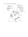
4.3 Maintenance of Air Compressor ........................................................................... 4-8
4.3.1
Checkup and Maintenance ..................................................................... 4-8
4.3.2
Troubleshooting of Air Compressor ........................................................ 4-10
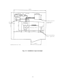
4.3.3
Location and Functions of Major Components ....................................... 4-11
-v-
Table of Contents (Cont’d)
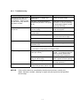
4.4
Troubleshooting .................................................................................................... 4-12
4.4.1
When Column Evacuation does not Work .............................................. 4-12
4.4.2
When Specimen Exchange Chamber Vacuum is not Good ................... 4-12
4.4.3
When Specimen Chamber Vacuum is not Good .................................... 4-13
4.4.4
When Ion Pump Vacuum Degraded ....................................................... 4-13
4.4.5
When Emission Current is not Set at Normal Value ............................... 4-14
4.4.6
When Image is not Shown on Screen .................................................... 4-14
4.4.7
When Image is Very Noisy ..................................................................... 4-15
4.4.8
When You cannot Correct Astigmatism.................................................. 4-16
4.4.9
When Auto Focus or Auto Stigma does not Work Satisfactorily............. 4-16
4.4.10 When S-4800 control program does not start up.................................... 4-17
4.4.11 When PC has Hanged up ....................................................................... 4-17
4.4.12 When Error Messages are shown .......................................................... 4-18
4.5 Operation for shutting down all power supply of S-4800 ...................................... 4-18
4.6 Operation when power was shut down by power line failure................................ 4-18
4.7 Operation for Starting S-4800 ........................................................................... 4-19
4.8 Operation when power line failure recovered ....................................................... 4-20
4.9 Operation when Water supply stopped by failure ................................................. 4-20
4.10 Gun Baking operation ........................................................................................... 4-21
4.11 Caution on Maintenance....................................................................................... 4-25
5.
REPLACEMENT PARTS ............................................................................................... 5-1
5.1 Consumables and Spare Parts............................................................................. 5-1
5.1.1
Consumables.......................................................................................... 5-1
5.1.2
Replacement Parts ................................................................................. 5-2
5.1.3
Spare Parts............................................................................................. 5-3
6.
ACCESSORY OPERATION .......................................................................................... 6-1
6.1 Model S-5080 Auto-Camera (Option) ................................................................... 6-1
6.1.1
Configuration .......................................................................................... 6-1
6.1.2
Specifications.......................................................................................... 6-3
6.1.3
Assembling the Camera ......................................................................... 6-5
6.1.4
Operation ................................................................................................ 6-6
SERVICE OFFICES
- vi -
1.
INSTALLATION
Only the persons who have been trained by a certified engineer of the manufacturer are allowed
to carry out the installation work described below.
1.1
1.1.1
Installation Requirements
General
For installing the Model S-4800, the sites and conditions mentioned below must be avoided
(1)
(2)
(3)
Room located in the vicinity of transformer substation
Room located in the vicinity of elevator
Location near electric equipment consuming a large quantity of power (e.g., electric
furnace) or its power supply
(4) Location near spark discharge source or high-frequency apparatus
(5) Room filled with gas which corrodes metals
(6) Place exposed to direct sunlight or strong draft
(7) Dusty place
(8) Location subjected to severe vibrations
(9) Using ground wire common to other electric equipment
(10) Location adjacent to radio or sound wave source
1.1.2
Room Temperature and Humidity
(1)
Room temperature..... 15 to 25 °C
Temperature fluctuation should preferably be less than 5 °C during operation of the
instrument
(2)
Humidity..................... 60% or less
The instrument should desirably be operated in air-conditioned room
1-1
1.1.3
(1)
Line Power Requirement
Single-phase AC, 4 kVA, 50/60 Hz.
When the supplied power line voltage is 100V, the instrument works by direct connection.
When the supplied power line voltage is other than 100V (200V or others), use a step down
transformer to step the power line voltage down to 100V. The transformer which meets to
the standard of the country shall be prepared locally.
Refer to 1.3.1 Power and Ground Wirings for connection method.
(2)
(3)
1.1.4
NOTICE:
(a) Line power fluctuation should be slow, and no abrupt fluctuation is allowable.
(b) Continuous energization is required
(c) Allowable line voltage fluctuation is ±10 % max.
AC Power Distribution Unit should be located within 10 m of the power distribution board on
the wall (since input AC cord is only 10 m long).
Be sure to use an exclusive power switch on the distribution board which is provided by the
user and feed the power through the switch.
Grounding
Connect the instrument to ground based on the standard of your country.
Avoid sharing the ground terminal with other power equipments. Be sure to ground the
instrument independently.
1.1.5
Water Supply and Drain
The following water supply conditions should be satisfied.
Water flow rate
: 1 to 1.5 L/min
Water pressure
: 50 to 100 kPa
Water temperature : 10 to 20 °C (temperature variation: 0.5 °C or less/10 min)
It is recommended to supply water via a cooling water circulation unit. When using city water,
natural drainage is required. If an appreciable amount of deposit is found, a proper water filter
should be attached. The drain port should be located at the floor level and water pressure must
be free from pulsation in a short cycle.
The water temperature for cooling the objective lens must be maintained so it is not more than 7
°C lower than the room temperature. Condensation will form when the difference between the
temperatures exceeds 7 °C. And if the SEM is used for a long time under the condition where
condensation forms, the objective lens area will become rusted and eventually be damaged, in
which case the complete set of objective lens parts will require to be replaced.
It is recommended to provide a water-leakage protection. Refer to Figure S-12 in Safety
Summary section.
1-2
1.1.6
Stray Magnetic Field
You should measure the stray magnetic field at the place for installing the Model S-4700 in
advance. When the requirements given in Table 1-1 are satisfied, no image trouble will occur.
Avoid locations at which abrupt electric current change or magnetic field change might occur due
to the presence of a large-sized magnetic clutch or power cable for other equipment.
Table 1-1
Acceleratin
g Voltage
Allowable
value
15 kV
1 kV
Stray Magnetic Field (at image recording)
Frequency
Component
Synchronous
Working
Magnification with Power
Distance
Supply AC
Magnetic Field
(effective value)
4 mm
1.5 mm
Frequency
Component
Asynchronous
with Power
Supply DC
Magnetic Field
Fluctuation
Change with
Time (drift)
220,000×
290 nT
(horizontal)
220 nT (vertical)
320 nT
(horizontal)
240 nT (vertical)
600 nT/min
(horizontal)
450 nT/min
(vertical)
120,000×
150 nT
(horizontal)
130 nT (vertical)
170 nT
(horizontal)
150 nT (vertical)
310 nT/min
(horizontal)
280 nT/min
(vertical)
nT:
NOTICE:
1.
2.
3.
4.
5.
6.
7.
Nanotesla
The frequency component synchronous with power supply (AC magnetic field) is
an effective value. Therefore, its allowable value should be increased to 2.8
times for evaluation in terms of p-p (peak to peak) value.
The DC magnetic field fluctuation stands for a rapid change of stray magnetic
field with time lapse. A gradual and moderate change with time lapse is
handled as a temporal variation (drift).
The temporal variation (drift) of stray magnetic field signifies a difference
(maximum drift) between the maximum and minimum levels within the specified
time (1 minute).
The allowable value of AC magnetic field is determined so that image distortion
(elongation, contraction or curving) at the specified magnification will not exceed
0.5 mm.
The allowable value of DC magnetic field fluctuation is determined so that image
disturbance (image shift or spike noise) at the specified magnification will not
exceed 0.2 mm on a micrograph.
The allowable value of temporal variation (drift) in stray magnetic field is
determined so that image sway due to that temporal variation will not exceed
0.5 mm on a micrograph taken at the specified magnification.
Fluctuation-free DC component (excluding terrestrial magnetic field) of stray
magnetic field will not cause the electron beam to sway. Therefore, image
1-3
remains unaffected so far as the field strength is within a few ten µT.
The allowable values given in Table 1-1 are applicable at the specified working
distances (4 mm at accelerating voltage 15 kV and 1.5 mm at 1 kV). At a longer
working distance, the allowable value of stray magnetic field becomes smaller.
(Namely, image is apt to be affected by stray magnetic field.)
8.
1.1.7
Floor Vibration
You should measure the floor vibration at the place for installing the Model S-4700 in advance.
When the requirements given in Table 1-2 are satisfied, no image trouble will occur.
If the instrument is installed on the first floor in a reinforced concrete or steel frame building, the
instrument performance will not be degraded by external vibrations so long as vibration sources
such as heavy-duty machine tools or transportation facilities (electric car, for example) are not
operated nearby.
Table 1-2
Floor vibration:
Vibration
Frequency
(Hz)
1.0
1.4
2.0
3.0
4.0
5.0
6.0
10.0
Allowable Vibration
Image trouble will not be observed when the conditions below are satisfied.
S-4800 Type I
Allowable Amplitude (X, Y)
Vibration
Frequency
(Hz)
1.0
2.0
3.0
3.5
4.0
5.0
6.0
10.0
(µm Peak to Peak)
Less than 7.0
Less than 2.0
Less than 2.0
Less than 4.0
Less than 4.5
Less than 4.5
Less than 4.0
Less than 3.0
Allowable Amplitude (Z)
(µm Peak to Peak)
Less than 25.0
Less than 14.0
Less than 5.0
Less than 2.9
Less than 1.8
Less than 1.0
Less than 1.1
Less than 1.2
S-4800 Type II
Vibration
Frequency
(Hz)
1.0
1.5
2.0
2.4
3.0
5.0
6.0
10.0
NOTICE:
Vibration
Frequency
(Hz)
1.0
2.0
3.0
4.0
5.0
6.0
7.0
10.0
Allowable Amplitude (X, Y)
(µm Peak to Peak)
Less than 8.0
Less than 3.0
Less than 1.4
Less than 1.4
Less than 3.0
Less than 4.0
Less than 3.5
Less than 3.5
Allowable Amplitude (Z)
(µm Peak to Peak)
Less than 20.0
Less than 10.0
Less than 5.0
Less than 2.7
Less than 1.8
Less than 1.0
Less than 1.0
Less than 1.0
The allowable amplitude corresponds to an image deviation of less than 0.2 mm
on a 5 inches x 4 inches size micrograph at magnification 220,000×.
1-4
Figure 1-1 shows the relation between frequency of floor vibration and vibration transmittance of
the instrument. Since the vibration transmittance is maximum at the resonance point (about
2 Hz) of the anti-vibration mount provided with the instrument, the allowable amplitude is
minimum at this point.
Please consult with us if the floor vibration exceeds the allowable values. (Vibration
should be measured in advance if it is expected to cause a disturbance.)
Low frequency
vibration range
Transmittance Tr
NOTICE:
5 Hz
Frequency : fn
Resonance point
Fig. 1-1
Vibration Transmittance - Frequency Characteristics
1-5
1.1.8
Power Line Noise and Electric Field Noise
Image troubles may be observed when a device as given in Table 1-3 or its power line is
installed nearby or, even if it is distant, it is a heavy duty type. When selecting the installation
site, therefore, whether a source of interference is located nearby or not must be checked.
In case an equipment energized by power of a frequency different from the commercial
frequency employed on the Model S-4800 or the power line for it is located nearby, scan
synchronization with power line frequency will become ineffective. Such a location should be
avoided.
Table 1-3
Classification
Small-sized
electric
equipments
Equipment using
high frequency
Power equipment
Large power
radio frequency
equipment
Noise
Source
Source Equipment
Electric equipment
with contacts
Electric discharge
(spark, arc)
Flasher (neon sign, ornamental electric bulb),
relay, electromagnetic contactor, thermostat
(warmer, refrigerator, heating iron), cash
register
Equipment utilizing
commutator motor
Electric discharge
(spark, arc),
sliding contact
Electric drill, laboratory engine, motor of
sewing machine, cleaner, food mixer, shaver,
massaging machine
Electric discharge
tube
Glow discharge
Neon discharge tube, high pressure mercury
arc lamp
Controller utilizing
semiconductor
Phase control
(transient noise)
Thyristor dimmer, inverter
Industrial high
frequency equipment
Electro-magnetic
emission
Industrial high frequency heater, high
frequency electric welder, microwave oven
Medical high
frequency equipment
Electro-magnetic
emission
VHF/UHF fulgurators, electric scalpel
Equipment utilizing
ultrasonic wave
Electro-magnetic
emission
Flaw detector, depth sounder, fish finder,
ultrasonic cleaner
Power cable
(transmission line)
Electric or magnetic
filed,
Ground current
Induction of commercial frequency
(electrostatic induction, electromagnetic
induction, current leaking in ground)
Electric discharge
(corona, arc)
Corona, poor insulator, poor contact due to
corroded metal (arc discharge)
Electric discharge
(spark, arc)
Trolley wire, internal equipment, rectifier
Magnetic field
Current flow deviation
Electric discharge
Ignition system
Other
Dynamo, voltage regulator, wiper, horn,
winker
Electro-magnetic
emission
Broadcasting equipment, radar
Electric railroad / train
Internal
combustion
engine
External Noise Sources
Automobile
Electro-magnetic
emission
.
1-6
Radio transceiver
1.1.9
Disturbance by Sound Waves
Sound waves (vibrations of air) adversely affect the Model S-4800 regardless of their frequency
and may cause image trouble. To prevent this, confirm before installation that equipment which
may cause a sonic disturbance is not located in the vicinity of the S-4800. If such equipment
exists, then check for noise level.
In general, as the frequency of noise increases, the sound pressure level decreases, and the
frequency of noise varies depending on the cause of noise. It is therefore necessary to carry
out noise frequency analysis at the installation location of the S-4800 SEM to check the degree
of noise (effective factor) in each case.
Frequency : f (Hz) Allowable Noise Level(Type I) Allowable Noise Level (Type II)
f≦150
75 dB or less
72 dB or less
1.1.10
Site
Requirements
150≦f≦800
60 dB or less
60 dB or less
800≦f≦2000
54 dB or less
52 dB or less
1.1.10
Site requirements
(1)
Space required
A room of about 3.4 × 3.0 m is desirable.
(2)
Minimum dimensions of entrance
0.95 (W) × 1.7 (H) m
(3)
Durability of floor
Floor loading capability (kg / m 2 ) Total mass of equipment (kg)
≥
3
Floor area of the room (m 2 )
(4)
Instrument layout
See Fig. 1-2 for the layout example.
1-7
3400
RP
(500)
Weight
230
(540)
225
526
400
960
Main
column
unit
Display unit
(800)∗1
840
1000
(400)
966
3000
Air
compressor
Cooling water
circulator
(option)
(225)
Photographing
unit (option)
1100
Dimensions in mm
Fig. 1-2
Installation Layout example
1-8
1.2
Materials or Instruments to be prepared by User
See Table 1-4.
Table 1-4
Name
Materials or Instruments to be Prepared by User
Quantity
Remarks
Ethanol
500 mL
Used for cleaning parts.
Acetone
500 mL
Used for cleaning parts.
Liquid nitrogen
2 L/day
For cooling the anti-contamination trap.
Vacuum evaporator
1 set
Used to evaporate carbon onto specimen or bake out
aperture plate.
Magnetron spattering coater
1 set
Used to coat metal onto specimen, or for coating metal
onto aperture plate.
Ultrasonic cleaner
1 set
Used for cleaning parts.
Desiccator or the like
1 set
For storing delicate parts.
Optical microscope
1.3
1 unit
For checking specimen and aperture
Wiring
Only the persons who have been trained by a certified engineer of the manufacturer are allowed
to carry out the maintenance work described below.
Only cautions with respect to wiring are described here.
1-9
1.3.1
Power and Ground Wirings
The instrument operates only with a power supply of AC100 V.
If using a power voltage other than AC100 V, the double insulation transformer (option) is
required.
The transformer shall be put after MAIN switch of S-4800. Fig 1-3 shows connection of the step
down transformer.
Safety circuit
Remove short cable
MAIN-ELB
100V
100/200V
Current
Braker
200V: 32A
Fig 1-3
UL/CE:Double Insulation
Connection of the step down transformer
To connect the transformer, remove the left side part of the rear cover of display unit.
Remove the provided two short circuit cables put on the TB1 terminal of the power distribution
unit.
Connect the cable of input of the transformer to I(L) and 2(N) , and the cable of output of the
transformer to 3(L) and 4(N) terminals of the TB1. Refer the following fig 1-4 for connection.
Remove short cables
TB1 TRANS (OPTION)
1(L) 2(N) 3(L) 4(N)
To step down
transformer
From
Transformer
Fixing band for cable to transformer
Main Power
To Column
Unit
To step down
transformer
Fig 1-4 Connection of the step down transformer
The cable of the step down transformer shall be prepared locally with the transformer.
1-10
Use 8 square mm cable with M5 wire terminal.
CAUTION
Be sure that the output of the step down transformer is AC100V ±10%. Irregular connection
causing higher voltage will result serious damage to the equipment.
Alternately the step down transformer may be put at the input of S-4800.
In the case, connect the input of the transformer to the main breaker of the site power supply.
Connect the out put to the Main breaker (ELB) of S-4800. Refer fig 1-5 for the connection.
However, the former way (put the step down transformer next to the S-4800 Main breaker) is
strongly recommended for safety.
Safety circuit
MAIN-ELB
100/200V
Short
100V
Step Down Transformer
Fig 1-5
Current
Breaker
50A
Connection of the step down transformer
In both of above cases, ground the instrument at a grounding resistance lower than 100 ohms.
The grounding terminal must not be common to other electric equipment, i.e. exclusive grounding
should be provided.
NOTICE
The instrument provides one of following two types of Main ELB.
(1) For using with 200 to 240V power line
Leakage current breaker (with key lock, CE/UL conforming)
Capacity
: 6.4kVA
Maximum current
: 32A
Sensitive current
: 30mA
Short-circuit breaking capacity : 25kA
(2) For using with 100V power line
Leakage current breaker(without key lock, CE or UL not conforming)
Capacity
: 5kVA
Maximum current
: 50A
Sensitive current
: 30mA
Short-circuit breaking capacity : 5kA
Instruments shipped to USA and Europe area and ordered to meet S2 guideline provide the
type of above (1).
1-11
2.
FUNCTIONS
Fig. 2-1a and 2-1b show the appearance of the Model S-4800 type 1 and Type2.
Main unit
Display unit
Fig. 2-1a
Model S-4800 System (type 1)
Fig. 2-1b
Model S-4800 System (type 2)
2-1
2.1
2.1.1
Control Knobs and Switches on Main Unit
Main unit (Column)
Fig. 2-2 shows the appearance of the S-4800 main unit (type I).
Beam monitor
preamplifier
Electron gun
Beam monitor aperture
Gun valve
Secondary electron
detector (Upper)
Anti-contamination
trap dewar
Objective movable
aperture
Secondary electron
detector (Lower)
Specimen stage
Specimen exchange
device
Evacuation control panel
Fig. 2-2
S-4800 Main Unit (type 1)
2-2
Fig. 2-3 sketches the sectional view of the S-4800 column.
Electron gun
IP–1
IP–2
Beam monitor aperture
1st condenser lens
IP–3
Gun valve (V-1)
Objective
movable aperture
2nd condenser lens
Deflection coil
Specimen
goniometer stage
Objective lens
Specimen
Specimen chamber
Fig. 2-3
Sectional View of S-4800 Column
2-3
Fig. 2-4 shows the Type 1 specimen stage.
Fine opening control X knob
Opening selector
Fine opening control Y knob
[T] control
[Z] control
Stage lock switch
[R] control
Absorbed
current
measuring
terminal
[X] control
[Y] control
Fig. 2-4
Specimen Stage (type I)
[X] control :
[Y] control :
[Z] control :
Moves specimen in X direction within a range from 0 to 50 mm.
Moves specimen in Y direction within a range from 0 to 50 mm.
Moves specimen in Z direction or shifts WD (Working Distance)
within a range from 1.5 to 40 mm.
(X-ray analysis position is at 15 mm working distance)
[R] control : Rotates specimen through 360° (continuously variable)
[T] control : Tilts specimen within a range from -5° to 70°.
[Absorbed current measuring terminal] : Measures beam absorbed current on specimen.
(Normally used as specimen applied voltage
terminal)
[Opening selector]
: Selects any of 4 aperture openings.
[Fine opening control X knob]
: Effects fine control in the direction for introducing or
taking out aperture.
[Fine opening control Y knob]
: Effects fine control in the direction orthogonal to the
above direction.
[Stage lock switch]
: Used for locking the specimen stage to reduce
vibration influence.
2-4
Fig. 2-5 shows the appearance of large specimen stage driven by motors (type II).
Fine opening control X knob
Opening selector
Fine opening control Y knob
Absorbed current measuring
terminal
(normally used for specimen
bias voltage terminal)
Fig. 2-5
Range of movement in X direction
Range of movement in Y direction
Range of movement in Z direction
Large Specimen Stage (type II)
:
:
:
Range of movement in R direction :
Range of movement in T direction :
0 to 110 mm
0 to 110 mm
WD = 1.5 to 40 mm
(X-ray analysis position is at 15 mm working distance)
360° continuously
-5° to 70°
2-5
Fig. 2-6a and 2-6b show the specimen exchange device of Type 1 and type2 instruments.
Specimen exchange
control switches
Exchange chamber
Viewing window
(a) Type1
Exchange rod
(b) Type2
Fig. 2-6 specimen exchange device
[Specimen exchange control switches ]
:
Switches for Gate valve control and evacuating / air introducing exchange
chamber.
[Viewing window] : Window to observe inside of specimen chamber when exchanging
specimens.
[Exchange rod]
: Transfer rod for specimen exchange.
2-6
Fig. 2-7 shows the block diagram of evacuating system.
MV1
MV2
MV3
Electron gun
chamber
IP1
1st
intermediate
Chamber
IP2
2nd
intermediate
Chamber
IP3
V1
GV
SEC:
Specimen
exchange
chamber
SC:Specimen
chamber
PiG-2
LV
PeG
PiG-1
TMP
BT
V3
RP
leak valve
V2
RP
Fig. 2-7
IP–1, –2, –3
TMP
RP
BT
:
:
:
:
GV
MV1 to MV3
V1
V2,V3
PiG–1
PiG–2
Pe
LV
RP leak valve
:
:
:
:
:
:
:
:
:
Evacuating System
Ion pumps
Turbo-molecular pump
Rotary pump
Buffer tank
Keeps back pressure of TMP while RP is evacuating
specimen exchange chamber.
Gate valve to isolate specimen chamber and exchange chamber
Manual valves to evacuate gun and intermediate chambers
Valve for gun and specimen chamber isolation
Vacuum valve
Pirani gauges to measure vacuum of specimen chamber
Pirani gauges to measure vacuum of specimen exchange chamber
Penning gauge to measure vacuum of specimen chamber
Leak valve to introduce air into specimen exchange chamber
Leak valve to introduce air into rotary pump
2-7
Fig. 2-8a shows the control panel for evacuation.
STAGE POWER
switch
S.C EVAC
switch
EVAC POWER
switch
S.C AIR
switch
IP RESET
switches
IP POWER switch
IP Backup PS
Operation area
(Option)
TMP
Indicator lamp
Fig. 2-8a
[EMERGENCY OFF] switch
[EVAC POWER] switch
[STAGE POWER] switch
IP Backup PS operation area
IP POWER switches
IP RESET switches
:
:
:
:
:
:
SC EVAC switch
:
SC AIR switch
TMP indicator lamps
:
:
APT HEATER switch
:
EMERGENCY
Display / Operation OFF switch
area
APT HEAT
switch
Evacuation Control Panel
Shuts down S-4800 entirely in an emergency.
Main switch of evacuation system.
Main switch of Stage controller (Type 2 only).
Optional Ion pump backup power supply operation area.
Power switches of ion pump high voltage.
Reset switches of ion pump high voltage.
Lamps inside of switches are lighten when IP high voltage is
ON.
Starts specimen chamber evacuation. The lamp blinks while
the sequence is advancing.
Starts introduction of air into specimen chamber.
POWER lamp indicates TMP power is ON. NORMAL shows
TMP is in normal running state.
When turned to AUTO, objective aperture heater will be on
when specimen chamber vacuum is high. When turned to
DEGASS, the heater is kept at higher temperature for
degassing. Set to AUTO for usual operation.
The lamp is lit while heater current is ON.
2-8
Fig. 2-8b shows the Display / Operation area.
Numeric / character
display
Status indicator lamps
Display mode
selection switches
Fig. 2-8a
Operation
switches
Display / Operation area
Vacuum of each chamber, status of evacuation sequence and messages are displayed on this
area.
• Status indicator lamps :
When each lamp (IP1 to SEC) is lit, it shows that the corresponding chamber is in good
vacuum.
Blinking lamp shows that the Numeric / character display is indicating vacuum of the
corresponding chamber. For example, when the SC lamp is blinking and the displayed
value is 3E-3, it indicates that vacuum of specimen chamber is 3x10⁻³ Pa.
• Display mode selection switches :
MODE : By pressing the switch, blinking status indicator lamp will move to next, in the
order of IP1ÆIP2ÆIP3ÆS.CÆS.E.CÆECOÆBAKEÆInitial (No indication).
SELECT : When the above status is in Initial, ECO and BAKE, the SELECT switch further
changes the Numeric / character display to lower level indication.
• Operation switches :
UP DOWN switch:
Increase or decrease time setting for ECO mode and BAKE mode
START STOP switch:
Start and stop baking and ECO mode.
• Numeric / character display
Indicates status code, vacuum, time and messages.
2-9
The display status changes as the following table by depressing the MODE switch.
Display
status
Status indicator
lamp
Initial status
IP1
IP2
IP3
S.C
No lamp blinks
IP1 lamp blinks
IP2 lamp blinks
IP3 lamp blinks
S.C lamp blinks
S.E.C
S.E.C lamp blinks
ECO
ECO lamp blinks
Numeric /
character
display
No indication
IP1vacuum
IP2 vacuum
IP3 vacuum
Specimen
chamber
vacuum
Specimen
exchange
chamber
vacuum
00.00
BAKE
BAKE lamp blinks
10.00
description
(Normal running status)
XE−Y (X−Y Pa)
XE−Y (X−Y Pa)
XE−Y (X−Y Pa)
XE−Y (X−Y Pa)
XE−Y (X−Y Pa)
Evacuation start time
(refer to ECO mode setting)
Baking time
(refer to 4.10 Gun baking)
In the initial status, the display status changes as the following table by depressing the SELECT
switch.
Display
status
Initial status
Date
Time
Cooling
water flow
Numeric / character display
description
No indication
XX.XX
XX.XX
FX.XX、F――――
(Normal running status)
month. day
hour. minute
Water flow L/min)
―――― shows water flow is off.
Other indication will appear on the Numeric / character display.
Numeric / character display
APXX
PdXX
E−XX
POFF
description
Waiting cooling time for the aperture heater before stopping
evacuation or introducing air into specimen chamber.
XX is in minutes.
Waiting the TMP stops its revolution. Pd means “Power
Down”.
XX is in minutes
Alarm or error message. XX is number of the message.
“Power off”. It shows that the evacuation power (pumps,
valves) is shut off (control power supply is on).
2 - 10
The following tables show alarm or error message and how to recover from the error.
Errors with (*) mark are caused by failure on equipment.
[Alarm for operation]
Message
No.
E10
(+ buzzer)
E11
(+ buzzer)
E12
(+ buzzer)
E13
(no buzzer)
description
recovering operation
Specimen exchange rod is not at
proper position when the GV is to
be closed.
Specimen exchange chamber is
not closed when the chamber
is to be evacuated.
Cooling water flow is les than
specified limit value.
Cooling water flow is over the
specified limit value.
Pull out the rod fully
Close the chamber.
Adjust water flow. Proper range of flow is
0.9 to 2L / min.
Adjust water flow. Proper range of flow is
0.9 to 2L / min.
[Alarm to be recovered by proper operation]
E14
(+ buzzer)
E15
(+ buzzer)
E08(+
buzzer)
E09(+
buzzer)
When using air compressor, check the
valve at the air output.
When using utility air, check the air
supply.
Air pressure for driving valves is
Evacuation sequence will recover when
lower than its limit value.
the air supply becomes normal
Evacuation sequence stops.
pressure.
If the alarm can not be recovered,
contact to service engineer.
Check that the cable for the heater (BNC
type connected to the objective lend
aperture from its down side.
If the alarm can not be recovered, turn
APT HEATER switch to OFF to stop
Aperture heater current is off
the alarm.
while the APT HEATER switch is
Contact to service engineer because
at AUTO or DEGAS.
operation without heating the aperture
will cause contamination on the
aperture plate.
TMP failure
TMP back pressure is too high.
2 - 11
Turn the EVAC POWER switch to off.
After “POFF” is indicated, turn the
switch to on.
If the error message appear again
contact to service engineer.
[Alarm according to gun baking]
Message
No.
E31(+
buzzer)
E32(+
buzzer)
E34(+
buzzer)
E35(+
buzzer)
E36(+
buzzer)
description
recovering operation
HV cable head is not placed to t
the cable holder properly.
Refer to 4.10 Gun baking.
Baking protection cover is not put.
Ion pump high voltage is not
applied.
Ion pump 1 vacuum degraded
while baking
Baking time setting is not correct.
[Alarm according to ECO mode setting]
E37(+
buzzer)
E38(+
buzzer)
Start gun baking while in ECO
mode
Evacuation start time must be 5
hours or more later from present
time.
E39(+
buzzer)
Start ECO mode while gun baking
E99(+
buzzer)
Specimen exchange rod is not at
its proper position or at present in
other errors (E01, E02, E03,
E05, E08, E09, E06, E14)
Refer to ECO mode operation
[Errors due to equipment failure]
E01(*)
E02(*)
E03(*)
E04(*)
E05(*)
E06(*)
E07(*)
Contact to service engineer
Control power supply error
(DC24V)
Control power supply error
(DC15V)
Control power supply error
(DC12)
Vacuum valve did not work
correct
Rotary pump (or dry pump) is not
working
GV did not work correct
Filament of Pi gauge broken
2 - 12
2.2
2.2.1
Control Knobs and Switches on Display Unit
Display
Figure 2-9 shows the display unit.
Monitor display
Keyboard
Manual
operation panel
Mouse
DISPLAY
Power switch
PC
(inside the door)
C980012
Fig. 2-9
Display Unit
• PC :
SEM control personal computer. Placed inside of the door.
• Monitor display:
Display monitor of PC. For adjustment of the monitor, refer to instruction manual of the
monitor. Model of the monitor display will be changed without notice.
• Manual operation panel:
Frequently used controls are placed on the manual operation panel.
• DISPLAY power switch:
Power switch of display unit. Power of PC also controlled with the switch.
Please be careful not to shut the power switch off before shutting down PC.
2 - 13
Fig. 2-10 shows the front panel of PC.
CD-ROM drive unit
FD drive unit
PC power switch
Power lamp
Hard disk accessing lamp
Fig. 2-10
PC Panel
• PC power switch
:
Power switch of PC. Usually the switch need not be used. PC power is controlled with
DISPLAY power switch.
• FD drive unit
:
Floppy disk drive. Be careful not to insert or remove disk while the access lamp is lit.
• CD-ROM drive unit
:
CD-ROM drive. Optionally changed to CDR/W drive.
• Hard disk accessing lamp :
Shows that hard disk is accessed.
Fig. 2-11 shows manual operation panel.
Magnification/Image shift control section
Stigma/alignment adjusting section
Brightness/Contrast adjusting section
Focus adjusting section
Fig. 2-11 Manual operation Panel
• Stigma/alignment adjusting section
[Stigma/alignment] [X], [Y] knobs :
Use for astigmatism correction in a usual practice. In the electron optics alignment
mode, these knobs serve for alignment adjustment.
• Focus adjusting section
2 - 14
[Focus] [Coarse] [Fine] knobs :
Use for coarse and fine focus adjustment.
• Magnification/Image shift control section
[Magnification] knob : Use for Magnification setting.
[Image Shift] knobs :
Move image by electrical image shift.
• Brightness/Contrast adjusting section
[Brightness] knob :
Use for brightness adjustment.
[Contrast] knob :
Use for contrast adjustment.
Fig. 2-12 shows the mouse.
The mouse has additional two side buttons, S and E button.
Right button
Left button
Wheel and Wheel
button
S button
E Button
Fig. 2-12 Mouse
Fig. 2-13 shows the track ball unit.
It is used for stage X and Y axis manual operation of Type2 model.
Upper buttons
Ball
Lower buttons
Fig. 2-13 Manual operation Panel
The trackball drives X and Y stage so as image moves to the direction of ball rotation. The
direction can be set inverse (refer to 3.9.15 optional setting)
When you turn the ball pressing down one of lower buttons, only X direction will be moved.
Alternately with one of upper button, only Y direction.
2 - 15
2.3
2.3.1
Graphical User Interface (GUI)
Starting the PC and logging in the S-4800 program
Use the following steps to log on to Windows 2000.
(1) Starting up the PC
Turn the DISPLAY power switch on. For some models of the PC, the power switch of the
PC shall be turned on.
(2) Log on
A message requesting key in will appear. Press Ctrl, Alt and Delete key simultaneously.
Then the logon dialog window will appear. Enter login name and password.
Use login name “S-4800” to operate S-4800. Initially no password is set for it.
The user may set or change password (refer to the manual of Windows 2000).
NOTICE Initially following users are set when sipped.
Administrator : Administrator level, no password
S-4800
: Power user level, no password
(“S-4800” is set to Power User level. It is because, different from NT, the Windows 2000
does not allow changing registry to User level)
For operation of Windows, refer to instruction manual for Windows 2000 (R).
S-4800 control program will start up automatically. When starting S-4800 control program after
once terminate it, select Start – PC_SEM on the taskbar. If the shortcut to it has been created,
double-clicking the PC-SEM
icon will start the S-4800 control program.
PC-SEM icon
( Windows 2000
(R)
Fig. 2-14 example of Windows desktop
is trade mark of Microsoft corp.)
2 - 16
The S-4800 login dialog window will open.
Fig. 2-15
S-4800 Loin dialog window
At the first starting up after installation of the program, use the log-in name [S-4800] and click the
OK button. You need no Password.
After log-in names and passwords for them are set, input the name and the password and then,
click the OK button.
NOTICE:
•
Setting and maintaining log-in names and passwords shall be done by the system
responsible person.
Refer to <3.9.17 Setting log-in name>
•
Setting or changing password for a log-in name once registered with above operation can be
made using the Password Setting dialog window.
Refer to < 3.9.16 Setting password>
2 - 17
2.3.2
S-4800 SEM Main Window
The following is the main window for operation of the microscope.
Minimize button
Size button
Close button
Operation Panel
Title bar
Menu bar
Control Panel
Operation Panel
Fig. 2-16
S-4700 Operation Window
Fig 2-16 S-4800 Main window
•
•
•
•
Title bar: Shows the window title
Minimize button:
Minimizes the window. The window is iconized and placed on the
Task bar
Size button:
The window status becomes Normal type. You can change the
window size. This button will be changed to Maximize button.
Close button:
Terminates the S-4800 operation program and close the window.
Menu bar: Clicking a main menu on the menu bar shows pull-down menus. Click one of
commands on the pull-down menu to execute the command.
Control Panel : Frequently used command buttons are placed on the control panel. Click a
button to execute the command.
Operation Panel: Basic functions are placed the Operation Panel. It has three tabs - SEM
(basic functions), STAGE (Stage operation) and Utility. The
button hides the
panel, and alternate
to left or right most side with
and
shows it again. Position of the panel can be moved
buttons.
2 - 18
Three modes of scanning image display are available, Full screen (shown on previous page),
Small screen (Fig 2-17 left) and Dual screen (Fig 2-17 right).
Fig 2-17 S-4800 Main window (Small and Dual screen mode)
2.3.3
Control arrangement on the window
Operation tools are placed as follows.
(1) Control panel
Control panel is similar as the tool bar of the S-4700 and S-5200 models.
Most frequently used controls are placed on it. Usual operation can be performed using the
Control panel and the manual operation panel.
(2) Operation panel
Operation panel has three tabs.
< SEM tab >
Scanning controls, electron optical column controls are placed on it.
< STAGE tab >
It has stage operation controls for type2 model.
< UTILITY tab >
Optional function controls are placed.
Functions to be placed on SEM and UTILITY tabs can be customized.
To change controls arrangement, open Setup dialog window by Op. Panel setting command in
Setup menu.
Also up to nine tool buttons are able to place on the tool button area (Lower part of Operation
panel).
2 - 19
(3) Menu bar
Almost functions are executed on the menu bar.
(4) Mouse operation on the scanning image
The S button of mouse changes operation on the scanning image alternately.
The following operations are available using mouse.
< Image adjustment >
Focusing, astigmatism correction and brightness / contrast adjustment
< Stage operation >
X / Y operation like a joystick, Rotation, Z and Tilt control and image shift
(5) Popup menu
By clicking the wheel button of mouse shows popup menus.
(6) Shortcut keys
Some shortcut keys are specified.
Refer to <2.3.20 Using shortcut keys>
2 - 20
2.3.4
Menu
The menu bar and the toolbar include the following menus and commands.
(1) File menu: The File menu includes commands for opening SEM Data Manager, saving files,
photo recording, and image printing.
• Open SEM Data Manager Opens the SEM Data Manager window.
Refer to <3.12 Using SEM Data Manager >
• Direct Save
Opens the Save Image dialog window. Use it for saving viewing
• Direct Photo
• Memory Photo
• Layout Print
• PCI Transfer
• Exit
images to disk. (To save captured images, use the Save
button in the Captured Image window.
Refer to <2.3.17 Save Image Dialog Window>
Executes Direct Photo recording.
Refer to < 3.6.7 Taking Photographs>
Executes Memory Photo Recording.
Refer to < 3.6.7 Taking Photographs>
Opens the Report Generation dialog window. Use it for printing
viewing images to a Windows-supported printer. To print
captured images, use Layout Print
button on Captured
Image window. And for saved images, use the print function on
the SEM Data Manager.
Refer to <3.9.11 Printing images using Report generation>
Transfers viewing image to Quartz PCI.
Closes SEM operation.
(2) Edit menu: The Edit menu includes commands for copying viewing images and attributes to
the Windows clipboard.
• Copy Image
• Copy Attribute
Copies viewing images to the Windows clipboard.
Refer to < 3.9.12 Copy Image>
Copies information of viewing images to the Windows clipboard.
Refer to < 3.9.13 Copy Image information text>
(3) Setup menu: The Setup menu includes commands for opening setup dialog windows for
operation of HV, column and others.
• HV
Opens the HV Control dialog window. Use it for setting
accelerating voltage, flashing operation or setting emission
current.
Refer to <3.3 Application of High Voltage >
2 - 21
• Column
• Condition Load
• Condition Save
• Image Display
• Photo Condition
• Data Display
Opens the Column tab of the Setup dialog window. Use it to
select the optimal electron optical column.
Refer to <3.4 Optimizing the electron beam>
Opens the Op. Cond. Tab of the Setup dialog window. Use it for
loading and reproducing previously saved electron optical
column condition.
Refer to <3.9.6 Operating condition memory>
Opens the Op. Cond. Tab of the Setup dialog window. Use it for
saving present electron optical column condition.
Refer to <3.9.6 Operating condition memory>
Opens the Image tab of the Setup dialog window. Use it for
setting the preset magnifications, contrast and brightness of
ABCC, capturing speed.
Refer to <2.3.8.2 Image tab>
Opens the Record tab of the Setup dialog window. Use it for
selecting scanning speed and other photo recording conditions.
Refer to <2.3.8.3 Record tab>
Opens the Record tab of the Setup dialog window. Use it to turn
data display On/Off and select specific information to be printed
on image.
Refer to <2.3.8.3 Record tab>
(4) Operate menu: The Operate menu includes commands for operation of column alignment,
motorized stage (Type 2 instrument only), auto functions etc.
• Alignment
• Sample Map
• ABCC
• Auto Focus
• Auto Stigma
• Focus Monitor
• BC Monitor
• Mag Mode
Opens the Alignment dialog window. Use it for column
alignment operation.
Refer to <3.4.3 Column Alignment operation>
Opens the Stage History dialog window.
Refer to <3.5.7.9 Stage History function>
Executes automatic brightness and contrast control.
Refer to <3.5.4 Image Brightness and Contrast Adjustment>
Executes automatic focusing.
Refer to <3.5.5 Focus and Astigmatism correction>
Executes automatic astigmatism correction.
Refer to <3.5.5 Focus and Astigmatism correction>ction
Starts Focus Monitor mode.
Refer to <3.5.5 Focus and Astigmatism correction>
Starts BC Monitor mode.
Refer to <3.5.4 Image Brightness and Contrast Adjustment>
Selects High Mag or Low Mag modes.
Refer to <3.5.2 Selecting Magnification>
2 - 22
(5) Scan menu: The Scan menu includes commands for scanning control.
• Run (Freeze)
• Capture
• Capture Reso
• Split DM Mode
• Scan Speed
• Arrange Speed buttons
• Scan Size
Runs or Freezes scanning alternately.
Starts image capturing.
Refer to <3.6.4 Image Capturing>
Selects capturing image resolution
Activates Split/Dual Mag mode.
Refer to <3.9.2 Split screen and Dual Mag mode>
Selects scanning speed.
Refer to <3.5.3 Selecting Scanning Speed>
Specifies scanning speed of each of 4 Scanning Speed buttons.
Refer to <3.5.3 Selecting Scanning Speed>
Selects the size of scanning image display (Screen mode) from
Full, Dual and Small.
Refer to ,3.9.1 Screen mode>
(6) Image menu: The Image menu includes commands for signal processing of optional
detectors.
• Opt. Signal Processing
Opens the Opt Signal Processing dialog window.
Refer to <3.9.5 Signal Processing>
(7) Analysis menu: The Analysis menu includes commands for analysis modes, measurement
and others.
• Normal
• Line Analysis
• Spot Analysis
• Area Analysis
• Oblique
• Measure
Sets to Normal mode (image observation).
Selects Line analysis 1 and 2 mode alternately.
Refer to <3.9.4 X-ray Analysis mode>
Selects Spot 1 and 2 mode alternately.
Refer to <3.9.4 X-ray Analysis mode>
Selects Area analysis 1 and 2 mode alternately.
Refer to <3.9.4 X-ray Analysis mode>
Opens Oblique image window and displays birds-eye view of
viewing images.
Refer to <3.9.14 Oblique Image>
If the CD-Measurement option is installed, the CD Measurement
dialog window is brought up. If the option is not installed,
measurement cursors appear on the image.
2 - 23
(8) Option menu: The Option menu includes commands for optional functions.
• Optional Setup
- Op. Panel Setting
• Optional Setup
- Toolbar Setting
• Optional Setup
- Stage
• Optional Setup
- Mouse Operation
• Optional Setup
- General
• Login Setting
• Password Setting
• Stage Calibration
Opens Op. Panel tab of the Optional Setup dialog window.
Use for arrangement of functions on the Operation Panel.
Refer to <3.9.15 Optional Setting>
Opens Toolbar Setting tab of the Optional Setup dialog window.
Use for arrangement of tool buttons on the Operation Panel.
Refer to <3.9.15 Optional Setting>
Opens Stage tab of the Optional Setup dialog window.
Use for setting parameters of stage control function.
Refer to <3.9.15 Optional Setting>
Opens Mouse tab of the Optional Setup dialog window.
Use for setting sensitivity of mouse operation.
Refer to <3.9.15 Optional Setting>
Opens General tab of the Optional Setup dialog window.
Use for setting various operation parameters..
Refer to <3.9.15 Optional Setting>
Opens the Login Setting dialog window. Use it for setting login
names and passwords for users. The dialog window can be
opened only when logined with the system managers login name.
Refer to < 2.3.14 Login Setting Dialog Window>
Opens the Password Setting dialog window. Use it for setting or
changing the password for the login name of the current user.
Refer to <2.3.16 Password Setting Dialog Window>
Starts calibration functions for stage controller.
(9) Window menu: The Window menu includes commands opening the Captured Image
window, and others.
• Captured Image
• Close All
• Opening window list
Opens the Captured Image window.
Refer to <2.3.9 Captured Image Window>
Closes all dialog window except for the Scanning Image window.
Lists present opening window. Selected window comes to front.
2 - 24
(10) Help menu: Opens Help for S-4700 SEM operation.
• Maintenance
Opens the Maintenance dialog window. Use it for checking
status of the Evacuation system, gun baking operation and
ECO mode setting.
• Index
• Search
• About FE-PC SEM
Show the index of S-4800 Help.
Show the key-word search of S-4800 Help.
Indicates the version of S-4800 PC-SEM.
(11) Undo menu : Recovers previous status of doing following operation.
Auto Focus
Auto Stigma
ABCC
Stage Drive
2 - 25
2.3.5
Control Panel
Most frequently used controls such that for Image observation, image recording.
Usual operation will be able to perform using the Control panel and the manual operation panel.
In case of present model S-4700 and S-5200, these controls are placed on the Toolbar and on
the top of the Scanning Image window.
2.3.5.1
Functional blocks on the Control Panel
HV Control
Scan control
Image recording
Auto control
Monitoring function
Magnification control
Stage, Image shift control
Fig 2-18 Control panel
2.3.5.2
HV control block
(1) HV ON/OFF and HV indicator
When vacuum of ion pumps and specimen chamber is better than the specified value, ON
button is enabled and HV indication blinks in yellow and blue color.
ON button applies high voltage to the electron gun and controls extraction voltage to obtain
the emission current. The ON button is changed to SET when high voltage is applied. The
SET button adjusts emission current.
OFF button shuts the gun high voltage down.
(2) HV control dialog window
gun high voltage value and emission current, or to execute flashing, click on the HV indicator.
The following controls are open under the HV indicator.
• Vacc select
button shows a pull down list of HV value. Select a voltage. Or
HV value is increased or decreased with
2 - 26
button in 100V steps.
When HV has been applied, click SET button after changing HV
value.
• Set Ie to
• Vext indicator
• Flashing button
button shows a pull down list of Ie (emission current) value.
Select a Ie value.
Extracting voltage value is indicated.
The button further opens Flasing controller. This button is disabled
while HV is applied.
(3) Flashing controller
• Intensity
• Execute button
Selects flashing intensity. Use “2” for usual operation.
Executes flashing. Emission current caused by flashing will be
indicated on the HV indicator about 2 seconds. Just after HV OFF
or after flashing, 30 seconds wait time is necessary. If click Execute
before 30 seconds passed, flashing will be executed after waiting
rest of time.
(4) Beam Monitor button
Beam Monitor function is provided to reduce the tip noise, which is a low frequency noise
caused by fluctuations of the emission current. Dividing the image signal by a reference
signal that is proportional to probe current can stabilize it. It is recommended to keep Beam
Monitor ON for normal operations.
When the indicator above Beam Monitor button is green, the beam monitor function is working.
If the indicator is OFF or blinking in red, click the button to turn it back on.
Beam Monitor adjustment (adjustment of the reference voltage) is activated automatically at
the start of ABCC function if Adjust Beam Monitor is checked in the ABCC area of the Image
tab of the Setup dialog window. Normally, check this box. Uncheck this box in special
cases such as when the Beam Monitor reference signal needs to trace the drift of the
emission current; for example, during quantitative X-ray analysis using a probe current drift
cancellation function, etc.
To disable beam monitor function, uncheck Beam monitor Active in the SCAN MODE block of
the Operation panel.
2 - 27
2.3.5.3
Scan control block
(1) Run button
when scanning and changed to
while scan
Run or freeze scanning. The button is
is frozen.
To stop scanning, click the button. Scanning continues until it goes to the end of the frame
and then, stops. If you wish to stop scanning immediately, click the button again.
(2) Scan speed buttons (TV1 to Red1 in above picture)
8 scanning speeds are assigned to 4 buttons. Each of buttons sets 2 scanning speed
alternately.
To assign scanning speed to each button, click
button. The following dialog will be shown.
Select a speed for each button and click OK.
2.3.5.4
Auto control
(1) ABC
Starts auto brightness/contrast adjustment (ABCC). If the results of ABCC are not adequate,
you can change the reference brightness and contrast in the Image tab of the Setup dialog
window. ABCC is applicable to SE and YAG BSE signal.
(2) AFC
Starts Auto Focus.
When magnification is lower than 5,000X, coarse focus (search using a wide focus range) is
carried out. Fine focus (search using a narrow focus range) is carried out at magnifications
higher than 5,000X.
Fine focus works correctly under conditions where the image is not clear but visible.
The result of Auto Focus depends on the surface structures of the specimen. When there is
2 - 28
little or no surface detail on the specimen, or when the specimen is charged, Auto Focus will
not operate properly.
2.3.5.5
Monitoring function
(1) Align
Opens Alignment dialog window and starts Aperture alignment.
Refer to <3.4.3 Column Alignment operation>
(2) Monit
Waveform monitor mode is activated. The focus monitor and B/C monitor modes are set
alternately by clicking the button.
By first click, A waveform is displayed for monitoring the focus. The magnification is set at
1,000X. Focus the image so that the waveform shows sharp peaks.
The next click changes the mode to B/C monitor. A waveform and reference lines are
displayed for monitoring contrast (amplitude of the waveform) and brightness (vertical level of
the waveform).
When the maximum and minimum values of the waveform are adjusted to fit within the upper
and lower reference lines, appropriate brightness and contrast will be obtained.
To terminate the focus monitor and B/C monitor mode, click the Cancel button in the massage
dialog shown while in the monitor modes, or click one of the Scan speed buttons.
Refer to <3.5.4 Image Brightness and Contrast adjustment> and <3.5.5 Focus and
Astigmatism correction>
2.3.5.6
Magnification control
(1) Magnification indicator area
Indicates magnification.
On the area, moving mouse pressing down left or right button changes magnification. To
increase magnification, drag the mouse to the right. To decrease, to the left.
For coarse changes, press the right button and for fine changes, the left button.
2 - 29
Alternately, click the area with the right button to increase or with the left button to decrease
magnification in a step.
(2) Preset button
The three preset magnifications are toggled through with each click of the button.
To set preset magnifications, open the Image tab of the Setup dialog window and input
desired values in the three Preset Magnification boxes.
A mark PM is indicated in the Magnification indicator area when the preset magnification is set.
(3) H/L button
To observe images at low magnifications of a few hundred times or lower, click the button. In
Low Mag mode, a mark LM is indicated in the Magnification indicator area. To return to High
Mag mode, click the button again.
2.3.5.7
Image recording
Record function select button
Record buttons
Capture resolution select button
Capure button
(1) Capture button
Captures an image with pre-specified image resolution and scanning speed.
Image resolution is selectable with the right side button and opening resolution list.
Select scanning speed on the Image tab of the Setup dialog window.
When capturing is started with TV or FAST1 scanning speed, frame integration is performed.
When started with SLOW1 to SLOW5 scanning speed a single frame Slow scan is performed.
Refer to <3.6.4 Image Capturing>
(2) Capture resolution select button
The button opens the following image resolution list. Select a resolution in the list.
The selected resolution value is indicated on the Capture button.
(3) Record buttons and Record function select button
There are five recording functions.
2 - 30
Direct Save : Opens the Save Image dialog window. Use it for saving viewing images to
disk. (To save captured images, use the Save
window..
button in the Captured Image
Layout Print :Opens the Report Generation dialog window. Use it for printing viewing
images to a Windows-supported printer. To print captured images, use Layout Print
button on Captured Image window. And for saved images, use the print
function on the SEM Data Manager.
Direct Photo :Executes Direct Photo recording.
optional photo recording unit is included).
(The button is effective when the
Memory Photo: Executes Memory Photo Recording (The button is effective when the
optional photo recording unit is included).
PCI Transfer :Transfers viewing image to Quartz PCI (The button is effective when the
optional PCI is installed).
Three of them can be placed on the Record button area.
To select record functions, click the Record function select button. The following list is shown.
Assign a record function to three button areas.
2.3.5.8
Stage, Image shift control
(Type2 and Type1 motorized stage)
(Type1 manual stage)
(1) Beam indicator
Indicates the present value of image shift with yellow cross mark.
To reset image shift to the center, click the indicator area.
(2) HOME button
Move the stage to its home position (X=35, Y=55mm). The indication window beside the
2 - 31
button is green when the stage is at home position.
(3) EXC button
Move the stage to the position for specimen exchange (X=35, Y=0mm). The indication window
beside the button is green when the stage is at specimen exchange position.
(4) !STOP button
Use the button to stop stage movement when, for example, started with incorrect stage
coordinates value.
(5) Lock button
Z and T axes are locked or released by clicking the button. The indication window beside the
button is red when the stage is locked. The button is changed to Release when stage is
locked. Z and T axes operation is disengaged while the stage is locked.
2.3.5.9
Extension for Dual screen mode
When the screen mode is Dual, the control panel is extended as follows.
Fig 2-19 Control Panel (Dual screen mode)
(1) Run / Freeze buttons
Run / Freeze button is changed.
button runs or freezes two scanning images simultaneously.
buttons runs or freezes A and B image each separately.
(2) Signal A /B selection
ABCC, brightness and contrast knobs on the manual operation panel is effective to the signal
selected here.
(Brightness and contrast adjustment with mouse operation works both to A and B image
separately)
(3) A B indication below the Capture button
The small indicators below the Capture button shows which screen is to be captured. You
can change the indication by clicking the indicators. Green color indicates corresponding
screen will be captured. When both indicators are set green, both A and B screen are
captured simultaneously.
2 - 32
(4) Record A / B selection
It selects which screen is to be recorded by Record functions.
2.3.6
Operation Panel
Operation Panel has three tabs.
Controls and setup tools for SEM operation are placed on the SEM and UTILITY tabs.
Arrangement of controls is possible to be customized over two tabs.
The STAGE tab contains controls for the specimen stage. All controls are available for Type2 5
axes motorized stage, and partially available for Type1 manual and Type1 3 axes motorized
stage.
The following pictures show typical arrangement.
SEM tab
STAGE tab
UTILITY tab
Fig 2-20 Operation panel
2 - 33
2.3.6.1
SIGNAL SELECT block
Signal select box
Right half image Signal select box
Signal addition indicator
SE detector selection
Signal control tools
GW BSE control button
BSE ratio selection box
(1) Signal select box
Selects image signal for Full and Small screen mode and the A image of Dual screen mode.
(2) Right half image Signal select box
Selects image signal for the B image of Dual screen mode and the right half image of Split /
Dual mag mode.
(3) Signal addition indicator
Controls adding two signals selected above Signal select boxes on the Dual screen mode.
When you click the left side indicator, it becomes green color and the mixed of the two signals
is displayed on the left (A) screen. If click the right side indicator, the mixed signal is displayed
on the right (B) screen. The signal addition is effective only on the Dual screen mode.
(4) SE detector selection
S-4800 SEM has two detectors, Upper and Lower. These have different characters and
therefore result different image information. Also mixed signal of two detectors is available.
Select with Mix / Upper / Lower buttons.
Refer to <3.5.1 SE detector>
(5) Signal Control tools
Ratio of SE and BSE included in the upper detector output signal is controllable with the tools.
When SE is selected, observing image will be of pure SE signal.
When +BSE is selected, amount of BSE signal is controlled by BSE ratio selection box.
Select a ratio from the pull down list clicking the arrow button. Low angle BSE will be detected
with L.A0 to L.A100. With larger number, amount of SE is suppressed and results BSE richer
image. H.A results high angle BSE image.
Refer to <3.5.1.2 Signal Control>
(6) GW BSE control (option)
Opens control dialog window for GW type BSE detector.
2 - 34
2.3.6.2
OPE CONDITION block
Probe Current mode selection box
Focus mode selection box
WD(Working distance) set / indicate box
WD range indication
Condition Load / Save button
Setup button
(1) Probe Current mode selection
Select Normal for resolution prior application or High for application needs large probe current.
Refer to <3.4 Optimizing the Electron beam>
(2) Focus mode selection
Select UHR or HR. In UHR mode, full working distance range is available. In HR mode, short
working distance range is limited but easier to use at long working distance.
Refer to <3.4 Optimizing the Electron beam>
(3) WD(Working distance) set / indicate box
When a working distance value is selected with the pull down list, focus point will be set to the
specified working distance. The box also indicates present focal length if varied with manual
focusing.
(4) WD range indication
Possible focusing range with present mode and accelerating voltage is indicated.
(5) Condition Load / Save button
Saving present column condition or retrieving previously saved condition.
Refer to <3.9.6 Operating Condition mamory>
(6) Setup button
Opens Column tab of the Setup dialog window for detailed column condition setting.
Refer to <3.4 Optimizing the Electron beam>
2 - 35
2.3.6.3
R.ROTATION block
Controls electron beam scanning direction to rotate image.
Rotation ON/OFF check box
Rotation angle set and indication box
Angle adjust slider
Angle adjust button
90°step rotate button
To activate raster rotation, check the ON/OFF check box.
Rotation angle can be set with the slider, clicking the side of slider, clicking the Angle adjust
button or with 90°step rotate button.
2.3.6.4
SCAN MODE block
Selects a scanning mode
Scaning mode buttons
Norm
Line
Spot
Area
Beam monitor active button
(1) Normal
Image observation mode
(2) Line
Displays a line profile of the signal intensity as a horizontal line in the observing image.
(3) Spot
Stops the scanning and places the electron beam at a specified point on the image.
Used for X-ray analysis of a point on the specimen.
(4) Area
Scans the electron beam in a selected frame in the image.
Used for X-ray analysis of a specified area on the specimen.
An advantage to this is that it allows an area-averaged spectrum as the beam is scanned over
a specified area, greater than the beam spot. Another advantage is that it reduces the
likelihood of specimen contamination in comparison with the stationary beam in Spot Analysis
mode.
(5) Beam monitor active button
Beam monitor is active when the box is checked.
2 - 36
2.3.6.5
SCAN SIZE block
Selects a screen mode.
(1) Full : Full screen mode
Scanning image is displayed on full desktop.
(2) Dual : Dual screen mode
Two image screens are displayed. Use the mode to observe different signal images
simultaneously or for color mixing image observation.
(3) Small : Small screen mode
Scanning image is displayed with a half size of desktop.
Faster frame speeds are available and in some case results better image quality.
2.3.6.6
DATA ENTRY block
Use for drawing shapes and characters in the scanning image.
Refer to <3.9.8 Data Entry function>
2 - 37
2.3.6.7
SIGNAL PROCESSING block
Applies real time digital image processing to the scanning image.
Processing selection box
Intensity selection box
(1) Processing selection box
Selects a processing
• Smooth :
Applies pixel averaging spatial filtering. Reduces snow noise.
Effective especially in case of high magnification image where the beam spot size is
larger than pixel size. For low magnification having fine structures, it may cause some
degradation of sharpness.
Two processing intensity selectable.
• Sharpen :
Increases sharpness of scanning image.
Two processing intensity selectable.
It may increase noise when the original image contains snow noise.
• Edge Enhance :
Similar but strong processing as Sharpen.
• Invert :
Color inversion. Resules negative image.
• Gammma :
Gamma correction.
-5 to +5 selectable.
(2) Intensity selection box
Selects a processing intensity.
(3) Option Signal button
Opens the Opt Signal Processing dialog window for analog signal processing of optional
detector signal.
NOTICE
The signal processing is not applied to pictures taken with Direct Photo function.
It is possible to apply similar spatial filtering to save images using SEM Data Manager.
2 - 38
2.3.6.8
TILT COMPENSATION block
Specimen tilting causes defocusing and magnification change to the tilt direction.
Tilt compensation is the tool to correct the two phenomena.
Dynamic focus check box
Dynamic focus set / indication box
Dynamic focus adjust slider
Dynamic focus adjust button
Tilt-magnification compensation check box
Tilt-magnification compensation set / indication box
Tilt-magnification compensation adjust slider
Tilt-magnification compensation adjust button
(1) Dynamic focus
Dynamic Focus scans the focal length linked with the scanning positions. When a specimen
is tilted, the field of view that can be focused is small (particularly at low magnifications and at
a short WD). Dynamic Focus function allows you to focus the beam for the entire field of
view.
Refer to <3.9.9 Raster Rotation, Dynamic focus and Tilt Compensation>
(2) Tilt compensation
When a specimen is tilted, magnification along the tilting direction is [cos (tilting angle)] lower
than that of a non-tilting direction. As a result, the image appears to be contracted in the
tilting direction. The image can be corrected at the magnification in all directions by using Tilt
Compensation function.
Refer to <3.9.9 Raster Rotation, Dynamic focus and Tilt Compensation>
2.3.6.9
COLOR MIXING block
The Color Mixing mode displays a color composite image. Each of three colors (Red, Green or
Blue) is assigned for two images signals for A (Left) and B (Right) screens, and displayed as a
color composite image.
This function is available only in Dual Screen mode. The color composite image is displayed on
the right (B) screen.
To display a color composite image, check the COLOR MIXING box and assign A or B signal (or
OFF) for the three colors by selecting the appropriate colors and. For example if the A signal is
SE and the B signal is BSE, and A is assigned to Blue and B is assigned to both Red and Green,
2 - 39
then a color composite image of yellow BSE and Blue SE is displayed.
image display mode, uncheck the COLOR MIXING box.
A color mixing image can be saved as a 24 bit color image file.
buttons and then, save the image.
Memory or direct photographing does not record color images.
2.3.6.10
To return to standard
Select B of the Record A/B
Scroll bar and area marker block
Sub Brightness control enhances image contrast by using post-processing after image
acquisition.
It is intended to use in cases where image signal is very few and final image contrast is very low.
When the value is 100, processing is not applied. Contrast is enhanced to 200 % by value 200.
It is recommended to set it to 100 in usual operation.
Note that effect of the processing is applied to 1280x960 pixels or smaller images. Also it is not
applied to photographed images.
2.3.6.11
Scroll bar and area marker block
Scrollbars for Stigma,Brightness and contrast is shown around the scanning image when the
Show Scrollbar is checked.
The area marker, which is a crosshair cursor crossing at the center of scanning iamge, is shown
when the Show Area Marker is checked.
2.3.6.12
Other optional function block
The CHARGE CONTROL and CELL COUNTING blocks are optional accessory. These are
shown only when the options are installed. Refer to the operation manuals for the optional
accessory.
2 - 40
2.3.6.13
Arrangement of control blocks
Above controls are placed on SEM and UTILITY tabs by user arrangement.
Open the Operation Panel tab of the Optional setup dialog window by selecting Option menu –
Optional Setup – Op.Panel Setting.
It is recommended to place frequently used controls on
the SEM tab, and others to Utility tab. If you do not use
some controls, remove them from both two tabs.
The names of control blocks are shown on the central
column. Simple description of the function and the view
of the block is shown when you click one of the block
name. When you wish to place the block on the SEM
tab, check the box under SEM tab. To place on the
Utility tab, check the box under Utility tab.
Uncheck both boxes for unnecessary blocks.
Because the tab space is limited, required space for
specified arrangement is calculated and if it is over
available space, the following messages will be shown.
In this case, close the message by OK button and
change arrangement.
[Move a block on the SEM tab to Utility tab.] or [Move a
block on the Utility tab to SEM tab.]
The OK button applies specified arrangement.
2 - 41
2.3.7
Mouse operation on the scanning image
Mouse operation tools for adjusting focus, stigma, contrast, brightness and specimen stage are
provided.
2.3.7.1.
Exchanging mouse control functions
Mouse operation tools are divided in three groups, focus/stigma/contrast/brightness and
specimen stage and no operation.
The S button of the mouse exchanges above groups.
Right button
Left button
Wheel and Wheel
button
S button
E Button
Fig 20-21 Mouse
2.3.7.2
Focus/stigma/contrast/brightness adjustment
The design of mouse pointer is changed corresponding to its position as shown below.
Fig 2-22 Mouse control (Focus/stigma/contrast/brightness)
2 - 42
Area
Coarse focus adjustment : move mouse horizontally pressing down right button.
Fine focus adjustment : move mouse horizontally pressing down left button.
Area
Stigma adjustment (X) : move mouse horizontally pressing down left button.
Stigma adjustment (Y) : move mouse horizontally pressing down right button.
Area
Brightness adjustment : move mouse horizontally pressing down left button.
Contrast adjustment : move mouse horizontally pressing down right button.
When the Show Scrollbar is checked on the Utility tab, adjustment scrollbars are placed on
the scanning image area.
It is possible to operate with these scrollbars.
Stigma Sliders:
Brightness and Contrast Sliders
2 - 43
2.3.7.3
Stage and image shift tools
Controls shown below will be shown on the scanning image.
Type1 manual stage
Type2 motorized stage
Fig 2-23 Mouse control (stage)
(1) Type1 manual stage
It is for image shift operation. Move the mouse pointer
to a position to be moved and
press down left or right button. The pointer will be changed to
mark. Move mouse to
target position holding down the button and then release the button.
If the above target position is near the center of the image area, the mause trace line is
changed and the target position is fixed to the center of image.
(2) Type2 motorized stage
All 5 axes are controlled with stage control tools. Refer to 3.5.7 for operation procedure.
2.3.8
Setup dialog window
The Setup dialog window has four tabs. To open the dialog window, use the following operation.
(1) Click the Setup
button on the Tool button area of the Operation panel.
(2) Select following commands from the Setup menu.
Setup – Column
: Opens Column tab
Setup – Condition Load : Opens Op. Cond tab
Setup – Condition Save : Opens Op. Cond tab
Setup – Image Display
: Opens Image tab
Setup – Photo Condition : Opens Record tab
Setup – Data Display
: Opens Record tab
(3) Click the Setup button on the OPE CONDITION block of the Operation panel
(4) Click the Load/Save button on the OPE CONDITION block of the Operation panel
2 - 44
2.3.8.1 Column tab
The Column tab is for setting operating condition of the electron optical column.
(1) HIGH MAG MODE block
Set column condition for High Mag mode.
(1-1) Probe current
Select Normal or High. For resolution prior
operation, use Normal. In case where larger probe
current is required, select High.
(1-2) Focus Mode
Select UHR or HR.
UHR mode is optimized for operation at short
working distance. Full working distance range
allowed for the present accelerating voltage can
be used.
HR mode is for use of rather long working
distance. Longer than about 5mm working
distance is able to be focused.
(1-3) Cond Lens 1
The check box On or Off excitation of the 1st
Condenser Lens.
Usually set it On (checked)
Select a excitation value with selection box. The range is 1.0 to 16.0. Higher number
results stronger excitation and then small probe current. Usual recommendation
value is 5.0.
For fine setting, use the up-down buttons.
(1-4) Cond Lens 2
The check box On or Off excitation of the 2nd Condenser Lens.
Usually set it On (checked)
(1-5) Focus Depth
Set ocus depth. Selectable range is 0.5 to 2.0. Resolution optimized condition is 1.0.
To increase focus depth, select larger number.
For usual operation, set it to 1.0 or larger to increase focus depth.
(1-6) Specimen Bias Voltage
Specimen Bias Voltage (-15V) is applied for optimum secondary electron detection.
Set it to ON for normal operation. Turn it off for some special applications such as
EBIC.
When operating the S-4800 at short working distance, you may end up with images
of uneven brightness throughout the field at low magnifications. We suggest to set
Specimen Bias Voltage at OFF in order to correct this problem.
When the specimen is tilted, however, the upper detector signal will decrease
2 - 45
particularly in the central field of view at low magnifications.
Low Mag mode for observation at low magnifications.
In such a case, use
Turning Specimen Bias Voltage ON and OFF may cause change of focus,
astigmatism and aperture alignment and need adjustment.
(1-7) Magnetic Sample
Astigmatism correction range is enlarged when the box is checked. Use it for
observation of ferromagnetic specimens such as iron that make astigmatism
correction difficult.
(1-8) Degauss button
The Degauss operation eliminates hysteresis of the magnetic field in the objective
lens.
When focus is changed greatly, accuracy of magnification or alignment of the
electron optical axis may degrade due to hysteresis of the focusing magnetic field.
Click Degauss button under the following conditions:
After changing focus widely.
Before making the electron optical axis alignment.
Degaussing is automatically effected when WD is changed in the Column Condition
raea, when the accelerating voltage is changed, or when a new Probe Current mode
is selected.
(2) LOW MAG MODE block
Probe Current mode and Cond Lens1 are set as same manner as in the HIGH MAG MODE
area.
These are selectable independently to High mag mode because in general the Low mag
mode brings less bright image if operated with the same column condition.
(3) ABCC Link
When the ABCC Link check box has been checked, ABCC will start automatically when some
of the column conditions are changed. Image brightness will be adjusted to adequate value.
2 - 46
2.3.8.2 Image tab
The Image tab is for setting operating condition regarding to image
observation.
(1) PRESET MAGNIFICATION block
Select or input desired value in the three preset magnification
boxes.
(2) ABCC block
If the results of ABCC are not adequate, you can change the
reference brightness and contrast. Adjustable range is –5 to +5.
(3) FAST SCAN AVERAGING block
Select number of frames to be averaged for TV1,2 and Fast1,2
speeds. Recommended numbers are 4 for TV1 and 8 or 16 for
TV2, 2 for Fast1 and 4 for Fast2. The higher the number of
frames, the better the attainable image quality. However, the
higher number results longer persistence time. Select optimal
value for present observing image.
NOTICE
The number of frames to be averaged are set for each screen mode (Full, Small or Dual)
independently. The value set while operating Full, Small or Dual screen modes are effective
when operating on each mode.
(4) CAPTURE SPEED/INTEGRATION block
Select number of frame integration for fast scan capturing in the Fast1, Fast2 boxes.
Select scanning speed for slow scan capturing in the Slow box.
(5) LINE PROFILE SIGNAL block
The signal for line profile can be selected independently with the signal for image. For
example, you can observe or take a photograph of an X-ray intensity line profile on the
secondary electron image. Select a signal for the line profile in the box.
When the Image is selected in the Background select buttons, the line profile is overlaid on
the image. When the Black is selected, only the line profile is shown on the screen.
2 - 47
2.3.8.3 Record tab
(1) AUTO DATA DISPLAY block
(1-1) Auto Data Display
Auto data display is engaged when this box is checked.
(1-2) Magnification to Time and Signal Name checkboxes
These items are include in data display if checked.
(1-3) Data Number input box
Input data number into this box. Up to ten characters
may be keyed in. Do not use "," (comma) and " "
(space).
If the Auto Increment check box is checked and the
Data Number has “-nn” at its end (n : numerals, for
example “Hitachi-00” ), Data Number is incremented
with each successive photographing.
(1-4) Back Ground Image checkbox
When this box is checked, the data display is overlaid
on the scanning image. If it is not checked, the
background of the data display area is black.
(1-5) Embed into Image checkbox
When this box is checked, the auto data display is
embedded into the image data when the image is
saved to disk. If it is not checked, only the image data
is saved. This Setting is also applied for Print, Copy and PCI Transfer commands.
If the For Photograph is checked, the position of the auto data display in the saved
image is shifted slightly upward to ensure that it is properly framed in photographs. It
is recommended not to check the box if the saved image data will be used on the
computer only.
(2) PHOTO SPEED block
(2-1) Direct Photo
Selects a scanning speed for direct photo recording. The number of lines for the
selected scanning speed is shown under the box.
(2-1) Memory Photo
Selects number of scanning lines for memory photo recording.
Normal:
For 640×480 pixels image data
→960 lines (16/19 s photographing time)
For 1280×960 pixels image data
→960 lines (16/19 s photographing time)
For 2560×1920 pixels image data
→1920 lines (32/38 s photographing time)
Enhance:
2 - 48
For 640×480 pixels image data
→960 lines (16/19 s photographing time)
For 1280×960 pixels image data
→19200 lines (32/38 s photographing time)
For 2560×1920 pixels image data
→1920 lines (32/38 s photographing time)
(3) BRIGHTNESS/CONTRAST block
Sets brightness and contrast for photo recording. These are compensation factors for
brightness and contrast adjusted in the scanning image. Adjust these values if a photograph
does not have adequate brightness or contrast.
(4) FILM block
(4-1) Film Speed
Selects a film speed (sensitivity) of the film. The brightness setting is changed
internally according to the selected film speed.
(4-2) Photo Size
Selects a size of the film. The magnification is adjusted internally according to the
selected size.
×1.0: for 4×5 inches instant film
×0.8: for type 107 or 105 instant film
×0.6: for type 120 negative film
2 - 49
2.3.8.4
OP. Cond tab
This function is provided for saving and loading conditions of the electron optical column.
Save
Load
Fig 2-24 Condition Load/Save
For detail of operation, refer to < 3.9.6 Operating Condition memory >
2 - 50
2.3.9
Captured Image Window
Captured images are displayed as thumbnails on this window.
It opens when you captured an image. Also it can be opened by selecting Captured Image
command from Window menu or using the short-cut key (Ctrl + L).
The yellow border shows the present selected image. Tool buttons placed on the window are
effective for the selected image. To select plural images, click thumbnails pressing down the Ctrl
key. The window shows up to 16 images. When 7 or more images are placed, a scrollbar will be
shown and images are scrolled horizontally.
Thumbnail : Selected by clicking. Double click opens the
image on viewer window.
Image information : Signal, accelerating voltage and magnification
are indicated.
Fig 2-25 Captured Image window
Save button : Saves the selected image. If started when plural images are selected,
these aresaved at once using All save option.
Delete button : Deletes the selected image.
View button : Open the selected image on the viewer window.
Layout button : Opens the Report Generation window for printing the image. To add
other captured images on the sheet of the Report Generation window, double-click
the image.
Cond button : Opens the Ope. Cond tab of the Setup dialog window bringing the image
and column condition when the image was captured.
Photo button : Start memory photographing of the selected image.
Stage button : Move the stage to the position where the selected image was captured.
It is effective for the Type2 motorized stage.
PCI button : Transfers the selected image to ”Quartz PCI” database program.
It is effective when the ”Quartz PCI” has been installed.
Close button : Closes the window. Thumbnails are not cleared by closing the window.
You can open again
: When the box is checked, auto data display and data drawn with the Data
Entry function of captured instance are recorded with the image.
Refer to < 3.6.4 Image Capturing > and < 2.3.34 Save Image Dialog Window >
2 - 51
2.3.10
SEM Data Manager Window
SEM Data Manager is an image-filing program with an easy-to-operate database function.
Images are registered to the database automatically when saved.
For detail, refer to <3.12 Using SEM Data Manager>
2.3.11
Alignment Dialog Window
The Alignment dialog window is used for alignment operations.
To open the dialog window, click the Wobbler
button in the Scanning Image window or the
button on the toolbar. Or select the Alignment command from the
Column Alignment
Operate menu. When the dialog window is opened with the Wobbler button, Aperture Alignment
(when the magnification mode is High Mag) or Low Mag Position (when the magnification mode
is Low Mag) starts as the default setting.
Refer to <3.4.3 Column Alignment Operation>
Function select buttons
Alignment operation area
Next step button
Fig 2-26 Alignment window
1. Function select buttons
2. Aperture Align button
3. Reset button
4. Reset All button
5. Alignment
operation area
6. Close button
7. Next step button
Starts each alignment function. Off stops functions.
Starts Aperture Alignment function. It is the same as the Aperture
Align select button. But it is an independent button since it is used
frequently.
Resets alignment of the selected function.
Resets alignment of all functions.
This area is used for adjustment operation. When the mouse pointer
is
, you can make adjustment both in X or X direction by
moving the mouse pressing the left button. When the mouse pointer
is
or
, adjustment direction is restricted in X or Y direction.
Stops alignment operation and closes the dialog window.
Activates next alignment function.
F4 key steps to the next alignment function, and Shift + F4 key to previous function.
2 - 52
2.3.12
CD Measurement dialog window (option)
Refer to the operation manual of the function.
2.3.13
Comm Port Setting Dialog Window
Set parameters for the RS-232C communication ports. Use this command only when the change
of the parameters are required. Unexpected change of the default parameters may cause
troubles.
It opens by selecting Comm Port Setting command from the Option menu.
Comm Port
Speed
Character Length
Parity
Stop Bit
Hand Shaking
Retry
2.3.14
Selects one of communication ports.
Selects communication speed in baud rate.
Selects character length.
Selects parity bit status.
Selects stop bit status.
Selects hand shaking method.
Select number of retry.
Login Setting Dialog Window
It opens by selecting Login Setting command from Option menu. It is possible only when
logined with the login name [S-4800].
You can create or change login names and their password for each users.
Refer to <3.9.17 Setting Login Name>
2 - 53
2.3.15
Oblique Dialog Window
The Oblique dialog window is used to display an oblique image. To open the dialog window,
select the Oblique command from the Analysis menu.
Refer to <3.9.14 Oblique Image>
2.3.16
Password Setting Dialog Window
Use the Password Setting Dialog Window for setting or changing the password of the login
name for current user.
To open this dialog window, select the Password Setting command from the Option menu.
Refer to <3.9.16 Password Setting>
2 - 54
2.3.17
Save Image Dialog Window
The Save Image dialog window is used for saving scanning images or captured images.
To save scanning images, Use the Direct save button on the Control panel. Use the save button
on the captured image window to save captured images.
Refer to <3.6 Saving and Recording Images>
2.3.18
Opt Signal Processing Dialog Window
The Opt Signal Processing dialog window is used to apply analog processing to signals of
optional detector signal.
Refer to <3.9.5 Signal Processung>
2.3.19
Split/Dual Mag Controller
Split Screen mode displays two images in the viewing area, and allows images to be displayed
having different signals and at different magnifications. The Split Screen mode is available in
Standard Screen mode.
To open this controller, select the Split DM command from the Scan menu.
Refer to <3.9.2 Split Screen and Dual Mag mode>
2 - 55
2.3.20
Using Short-Cut Keys
Short-cut keys are available for execution of many commands.
(1) Using short-cut keys
Input Alt + [underlined character in a main menu command] opens the pull-down menu. And
then, [underlined character in a pull-down menu] executes the command. For example, Alt +
F opens the File menu and S key executes the Direct Save command.
While a pull-down menu is open, arrow keys ↑(←)↓(→)select commands in order.
The Enter key executes the selected command.
(2) Using Ctrl + ~ keys or Functions keys
Some frequently used commands are executed using this type of short-cut keys.
They are;
Ctrl + O: Open SEM Data Manager
Ctrl + P: Print
Ctrl + C: Copy Image
Ctrl + L: Open Captured Image window
F1:
Help can be opened
F5:
Runs or stops scanning alternately
F4:
Changes Alignment mode to the next step.
Shift + F4: Changes Alignment mode to the previous step
(3) Selection of alignment operations
Using F4 key, you can activate alignment functions in order. Shit + F4 key in reverse order. It
is useful as alignment operations are to be done in order of buttons, Beam Align to Low
Mag Position.
2 - 56
3.
OPERATION
Shown below is the procedural flow of typical SEM operation. For details, refer to each
subsection.
3.1 Preliminary Operation
• Check of Column Vacuum .................................. (3.1.1)
• Starting the Display............................................. (3.1.2)
• Use of Anti-Contamination Trap and Cold Trap . (3.1.3)
3.2 Specimen Setting
•
•
•
•
•
3.3 Application of High Voltage
Cautions on Specimen Preparation....................(3.2.1)
Specimen Preparation for Materials ...................(3.2.2)
Adjustment Specimen Height .............................(3.2.3)
Specimen Exchange Position ............................. (3.2.4)
How to Set Specimen ......................................... (3.2.5)
• Flashing ..............................................................(3.3.2)
• Setting of Accelerating Voltage and
Emission Current ................................................(3.3.3)
• Application of High voltage .................................(3.3.4)
3.4 Optimizing the Electron Beam
• Selecting Electron Optical Column Condition.....(3.4.1)
• Column Alignment Operation..............................(3.4.2)
3.5 Operation for Image Observation
•
•
•
•
•
•
3.6 Saving and Recording Images
3.7 SEM Data Manager
Selecting Magnification.......................................(3.5.1)
Selecting Scanning Speed..................................(3.5.2)
Image Brightness and Contrast Adjustment .......(3.5.3)
Focus and Astigmatism Correction.....................(3.5.4)
Operation of the Specimen Stage Type 1 ..........(3.5.5)
Operation of the Specimen Stage Type 2 ..........(3.5.6)
•
•
•
•
Saving and Recording Images ...........................(3.6.1)
Setting Conditions for Image Capturing..............(3.6.2)
Image Capturing .................................................(3.6.3)
Saving an Image Displayed
in the Scanning Image Screen (Direct Save) .....(3.6.4)
• Saving Captured Images ....................................(3.6.5)
• Taking Photographs............................................(3.6.6)
• Precaution about SEM Data Manager................(3.7.1)
• Registering Images
on SEM Data Manager Database.......................(3.7.2)
• Using SEM Data Manager ..................................(3.7.3)
3-1
3.8 Image Processing
3.9
At the End of Daily Use
• Contrast Conversion .......................................... (3.8.1)
• Image Processing .............................................. (3.8.2)
• Saving Processed Image ................................... (3.8.3)
•
•
•
•
•
Turning High Voltage Off ....................................(3.9.1)
Specimen Exchange Position .............................(3.9.2)
Taking the Specimen out of the Chamber ..........(3.9.3)
Turning the Gun Valve Switch Off ......................(3.9.4)
Closing Windows and Shutting
the Display Power ...............................................(3.9.5)
3.10 Using Other Functions
3.11 Image Quality
3.12 Mechanical Column Alignment
3-2
3.1
3.1.1
Preliminary Operation
Check of Column Vacuum
At the beginning of SEM operation, check the evacuation control
panel. The following conditions must be met:
(1) Lamps of IP1, IP2 and IP3 RESET switches are lit.
(2) Ion pump readings are better than the followings.
IP1: 2 × 10⁻⁷ Pa
IP2: 2 × 10⁻⁶ Pa
IP3: 5 × 10⁻⁵ Pa
(Pressing MODE switch on the Evacuation control panel shifts
forward the blinking of status display lamps. Read vacuum when
each of IP1 to IP3 lamp is blinking)
If vacuum readings do not satisfy the above conditions, gun
baking is required. Refer to “Maintenance” in section 4.
(3) EVAC POWER switch is set at 1 (ON).
(4) TMP POW ON, NORMAL lamps and the lamp of SC EVAC
switch are lit.
(5) Vacuum of S.C (specimen chamber) is better than 2x10⁻³ Pa.
(Read vacuum when S.C lamp is blinking)
(6) APT HEAT switch is set at AUTO.
Usually keep the APT HEAT switch on the evacuation control
panel at AUTO.
If the objective lens aperture is contaminated, charging will
degrade image quality and the image will drift because of micro
discharge. Such problems are noticeable at low accelerating
voltages. The aperture is heated to about 150ºC to remove contaminants to one tenth or less
of what it would be at room temperature.
The aperture heating will be turned OFF automatically when you press S.C AIR switch to
introduce air into the specimen chamber. The 30 minutes wait will be placed automatically
before introducing air when S.C AIR is started while APT HEAT switch is ON. The aperture
heating will start again when the specimen chamber vacuum recovered by S.C EVAC
operation. Note that after the aperture heating turned ON, image drift may be observed for
about half an hour.
3-3
3.1.2
Flow the cooling water
S-4800 requires water flow for cooling the objective lens coil. It is necessary while the Display
unit is powered on. A water valve is provided and is open when the S-4800 control program
starts up. It is closed when the POWER switch of the display unit is turned off.
(1) When supplying water by city or site water source
Open the water source valve before turning the display power to on. If the display is started, a
message will be shown (Objective lens over heat or water is not supplied). Check and flow
water.
(2) When using a water circulator
If the circulator power is linked with S-4800, It will start running when the S-4800 control
program starts up.
If it is not linked, turn the circulator power to on before starting S-4800 control program.
(3) Adjusting water flow
Water flow will be indicated on the Evacuation control panel. Set the indicator to initial status
( no indication) with pressing MODE switch and repeat pressing the SELECT switch so as the
indicator show [F X.X]. The X.X shows water flow in Litter / minute. For example F 1.5
indicates 1.5 L / minute. Allowable water flow is within 0.9 to 2.1 L / Minute.
To adjust water flow, adjust the knob of the flow adjustment valve provided at the back of the
Main unit. To monitor the water flow, four lamps are visible through the window of the rear
cover.
Water flow adjust valve
Monitoring window
Monitoring lamps
The four lamps will lit as follows.(☼ shows lighting lamps)
● ● ● ● : 0 L / minute
●☼☼☼: 10.5 L / minute ← minimum value
☼● ● ● : 1.2 L / minute
☼● ●☼ : 1.35 L / minute
☼●☼● : 1.5 L / minute
← nominal value
☼●☼☼: 1.6.5 L / minute
3-4
☼☼● ● : 1.8 L / minute
☼☼●☼ : 1.95 L / minute
← maximum value
☼☼☼☼: 2.25 L / minute or more
(4) Warning message
When water flow is over the maximum limit, E-13 error will be shown on the Evacuation control
panel. No buzzer sounds in the case.
If it is less than the lower limit, error E-12 will be shown and buzzer sound, and a message
indicating (Objective lens over heat or water is not supplied) will be shown on the GUI. These will
be gone off when water flow is adjusted.
3.1.3
Starting the Display
(1) Turn the DISPLAY switch to 1 (ON).
(2) Windows 2000 will start up and request to key in [Ctrl + Alt +
Delete].
Then the logon dialog window will appear. Enter login name and
password. Initially no password is set for Administrator.
The user may set or change password (refer to the manual of
Windows 2000).
NOTICE
Use S-4800 on the Administrator level.
(4) The S-4800 system will start up automatically and the initial log-in dialog window appears.
(To start the S-4800 system after once closing it, select PC_SEM from start menu)
Input login name and its password. The SEM main window will open.
Refer to <3.9.16 Password Setting and 3.9.17 Setting Login Name>
3-5
3.1.4
Use of Anti-Contamination Trap
For image observation at high magnifications or low accelerating voltages, the use of the Anticontamination trap is recommended to prevent specimen contamination by hydrocarbon build-up.
The traps need to be filled with liquid nitrogen.
Injection funnel
The Anti-contamination trap is a plate above the specimen that adsorbs
gas around the specimen. The capacity of the liquid nitrogen dewar is
about 0.9 liters and is usable for about 5 hours at an ambient
temperature of 24°C. For initial filling, about 1.3 liters of liquid nitrogen is
required.
B980022
Dewar vessel
CAUTION
Before using liquid nitrogen, be sure to put on leather gloves and eye guard glasses. If liquid
nitrogen splashes on your skin, you may suffer frostbite. In addition, the room should be
ventilated to prevent oxygen depletion.
CAUTION
Never introduce air into the specimen chamber while the anti-contamination trap is filled with
liquid nitrogen. The anti-contamination trap will frost up and the vacuum will deteriorate.
Before introducing air into the specimen chamber, wait for a few hours after the liquid
nitrogen dewer has completely emptied. The air introduction valve does not have a protection
link with the cold trap.
3-6
3.2
3.2.1
Specimen Setting and Specimen Exchange
Cautions on Specimen Preparation
During specimen preparation, observe the followings.
(1) Use clean gloves when exchanging specimens. Holding the specimen or specimen stub with
bare hands should be avoided.
(2) Avoid using an excessive amount of conductive paste to fix a specimen on the specimen stub.
Ensure that the paste has dried before placing the specimen in the chamber.
(3) Select the correct specimen stub for each specimen.
(4) When using double-sided adhesive tape to fix a specimen to the stub, use the least amount
to minimize out-gassing. The use of double-sided adhesive tape may also cause specimen
drift.
3.2.2
Specimen Preparation for Materials
The method of specimen preparation varies with materials.
typical types of specimens.
Below are preparation methods for
(1) Conductive specimens such as metals:
These types of specimens can be observed without preparation. However, coating with heavy
metals by using a vacuum evaporator, an ion sputtering or magnetron sputtering unit may
result in better contrast.
(2) Non-conductive specimens such as semiconductors, fibrous specimens and polymeric
materials:
Coating with conductive materials is recommended. To observe these kinds of specimens
without a conductive coating use low accelerating voltages (1kV or lower). However, coated
particles may be more visible at higher magnifications.
(3) Biological specimens:
After dehydration, dry the specimen by using a method such as critical point drying, freeze
drying or other drying techniques, then coat the specimen with conductive material. A
cryogenic system is available as an option.
(4) X-ray analysis specimens:
Generally, polish the surface of the specimen, then fix it to the specimen stub using carbon
paste. Non-conductive specimens should be coated with carbon using a vacuum evaporator.
3-7
3.2.3
Adjustment of Specimen Height
Put the specimen stub on the specimen holder and adjust it to the proper height using the
specimen height gauge as shown in the figure. To adjust, loosen the lock screw and adjust the
specimen height so that the highest point of the specimen is the same as the bottom of the height
gauge. Then, tighten lock screw.
specimen
stub
lock screw
height gauge
CAUTION
Specimen height must be adjusted carefully. It must not be 0.5mm higher than the bottom of
the height gauge. If it is higher than this, the specimen may strike the objective lens and
cause damage when operating at a short working distance or at a high tilt angle. Also,
accurate setting of specimen height minimizes image shift during specimen tilting.
3.2.4
Specimen Exchange Position
(1) Type 1 (Manual stage):
Confirm that the Stage Lock is free (the lamp of Stage Lock switch is off).
Then set the X, Y, R, T and Z knobs of the specimen stage to the specimen exchange position.
Specimen exchange positions: X: 25.0 mm
Y: 25.0 mm
R: 0゜
T: 0゜
Z: 8.0mm
stage lock
Z
T
R
X
Y
3-8
(2) Type II (5-axis motorized stage):
Click the EXC button on the control panel. The stage is then moved to the specimen exchange
position, and the color of the indicator beside the button turns green.
Specimen exchange positions: X: 35.0mm
Y: 55.0mm
R: 0゜
T: 0゜
Z: 8.0mm
NOTICE:
Do not repeat clicking the EXC button. The Stop button may become ineffective by it.
NOTICE:
The specimen exchange position is not same as the stage home position. You need
to move to the home position by clicking the HOME button after setting specimen.
CAUTION
Start specimen exchange operation after the color of the indicator is changed green.
3.2.5
How to Set Specimen
Before setting a specimen on the specimen stage, make sure that the height of the specimen is
aligned with the height gauge mark.
3.2.5.1 Extracting specimen from stage
When a specimen is set inside the chamber, extract the specimen as follows.
(1) Move stage to its specimen exchange position.
After the color indicator becomes green, press the OPEN button on the specimen exchange
chamber.
Once the exchange chamber will be evacuated and then, the gate valve will open.
3-9
(2) Turn the knob of the specimen exchange rod clockwise so as the Unlock mark comes
upwards.
Insert the rod straightly and plug the two spring pins at the end of the rod to holes of the
specimen holder.
Turn the knob counterclockwise so as the Lock mark comes upwards to hook on the specimen
holder.
Looking in the chamber and confirming that the specimen holder comes out with the rod, pull
out the rod completely.
(3) Press the AIR button on the specimen exchange chamber. The gate valve is closed and air is
introduced into the specimen exchange chamber. Buzzer will sound after about 15 seconds to
inform completion of air introduction.
(4) Open the exchange chamber door.
(Type1)
(Type2)
Turn the knob clockwise and remove the specimen holder from the rod.
CAUTION
Do not hold the specimen exchange rod when opening and closing the specimen
exchange chamber. The rod may bend and disable specimen exchange.
3 - 10
3.2.5.2 Opening the specimen exchange chamber door
When a specimen is not set inside the chamber and the specimen exchange chamber has
been evacuated, open the exchange chamber door as follows.
(1) Press the AIR button on the specimen exchange chamber. Air is introduced into the specimen
exchange chamber. Buzzer will sound after about 15 seconds to inform completion of air
introduction.
(2) Open the exchange chamber door.
3.2.5.3 Setting a specimen
When a specimen is set inside the chamber, extract the specimen as follows.
(1) Turn the knob of the specimen exchange rod clockwise so as the Unlock mark comes
upwards.
Plug the two spring pins at the end of the rod to holes of the specimen holder.
(2) Turn the knob of the specimen exchange rod counterclockwise so as the Lock mark comes
upwards.
Confirm that the specimen holder is hooked to the rod.
Pull out the rod completely and close the exchange chamber door.
(3) Press the OPEN button on the specimen exchange chamber.
The chamber is evacuated and then, the gate valve will open.
(4) Looking into the specimen chamber, insert the exchange rod and set the specimen holder into
the stage by sliding it along the guide rails.
Turn the knob clockwise so as the Unlock mark comes upwards.
Pull out the rod completely confirming that the specimen holder does not move out with the rod.
(5) Press the CLOSE button on the specimen exchange chamber. The gate valve will be closed
and after about one minute, gun high voltage becomes applicable.
3 - 11
3.3
Application of High Voltage
3.3.1
Condition where the gun high voltage is applicable
You can apply high voltage when the HV display area on the control panel is blinking with yellow
and blue colors. When the indication is blue, high voltage can not be applied. It will be in almost
case because of vacuum degradation of specimen chamber or gun ion pumps. Also the
specimen exchange chamber must be evacuated and the gate valve must be closed.
While high voltage is applied, the indication is shown in yellow color.
3.3.2
Flashing
3.3.2.1 About flashing
Flashing is a procedure for removing gas molecules which have been adsorbed on the surface of
the cathode (FE tip) in the electron gun.
Flashing is needed as follows.
(1) Flash once everyday before use
When the emission current becomes unstable, flash again.
(2) Flash once at the end of daily operation
On the next day, start operation without flashing. Flash if the emission current becomes
unstable during operation.
3.3.2.2
Flashing Procedure
Use the following procedures for flashing.
(1) Click the HV display area on the control panel. The HV control dialog window will open.
(2) Click the Flashing button on it. The Flashing execution dialog window will open.
3 - 12
(3) Set Intensity to “2” and click Execute button.
The emission current value caused by flashing will be displayed on the Ie part of the HV
Display area about 2 seconds.
For normal flashing operation, use intensity “2”. However, when the stable stage of the
emission current is short, or the emission current begins to increase about 1 hour after
applying HV (in that case a large quantity of gas molecules are absorbed on the cathode), use
intensity “3”.
After flashing, the emission current decreases for a while, then becomes stable. (Even in the
stable period, the emission current continuously decreases slightly.) The emission current
becomes unstable and increases after 5 to 10 hours of operation.
Noise (bright or dark lateral stripes on the image) may appear in the initial period, but will
disappear in the stable period. When there is a large amount of noise and the emission current
becomes unstable, turn HV Off, and flash again.
A message will appear when 8 hours of accumulative operation time or 24 hours of total time
passed after flashing, as a reminder to flash the tip again.
If the tip is not flashed within 30 minutes, the HV will be turned off automatically.
The time period can be set at other value if necessary. Contact a service engineer to change the
time.
3.3.3
Setting of Accelerating Voltage and Emission Current
To set the accelerating voltage and emission current, use the HV Control dialog window.
(1) To set an accelerating voltage, select a voltage from the Vacc list box. Accelerating voltage
can also be set by using the keyboard to input a value followed by the Return key.
Also Up/Down buttons beside the listbox are available for 100V step setting.
(2) To set an emission current, select a current in the Set Ie to list box. It is recommended to set
it at 10 µA for normal operation.
Accelerating Voltage
Emission Current
Both accelerating voltage and emission current are adjusted immediately upon changing
them if the HV is on.
3 - 13
3.3.4
Application of High Voltage
When the HV Display are is blinking with yellow and blue color, click the ON button on the control
panel at the left of the HV Display area. Accelerating voltage (Vacc) and extracting voltage (Vext)
are then applied with the emission current values indicated in the HV display area.
The gun airlock - valve is opened automatically.
The ON button is changed to read SET when the high voltage is applied. You can set emission
current to a selected value in the Set Ie to box by clicking this button.
The OFF button shuts high voltage.
3 - 14
3.4
3.4.1
Optimizing the Electron Beam
Selecting a Magnification Mode
S-4800 provides two magnification modes, High Mag mode and Low Mag mode. Magnification
range of the modes are as follows.
High Mag Mode (HM)
: ×300 to ×800,000
(The lowest and highest magnification will be changed depending on present
accelerating voltage and working distance)
Low Mag Mode (LM)
: ×20 to ×10,000
Use the High Mag mode for usual observation, and the Low Mag mode for field searching.
Electron optical column conditions are set for both modes independently.
3.4.2
Selecting Electron Optical Column Condition
Electron optical column conditions need to be selected before alignment and operation of the
SEM begins.
For High Mag mode, use the OPE-CONDITION block on the Operation panel, and the Column
tab of the Setup dialog window for further detailed setting .
For Low Mag mode, use the Column tab of the Setup dialog window .
3.4.2.1 High Mag mode
Items need to be set frequently are placed on the OPE-CONDITION block.
Probe Current mode selection box
Focus mode selection box
WD(Working distance) set / indicate box
WD range indication
Condition Load / Save button
Setup button
(1) Probe Current mode
Select Normal or High in the Probe Current mode selection box. Normal is for high resolution
image observation. Use High for applications needs large probe current, such as EDX analysis.
(2) Focus Mode
Select UHR or HR.
In UHR mode, full working distance range is available. At working distance range longer than
about 8mm, the mode may cause somewhat rough focusing feeling.
In HR mode, working distance range is limited to about 5mm or longer. The mode is easier to
use at long working distance.
(3) Working Distance (WD):
Working distance (WD) is the distance between the bottom face of the objective lens and the
3 - 15
surface of the specimen. At a shorter WD, higher resolution is attainable.
At a longer WD, a larger tilt angle and a greater depth of focus is attainable.
Objective lens
WD
Specimen
When a WD is selected from pull-down menu, the objective lens current is adjusted in order to
focus an image at the specified WD.
This function is useful for:
1)
To obtaining focus of the specimen surface quickly after introducing a specimen.
2)
Focusing the specimen at a specific WD.
For X-ray analysis, the same WD (15 mm) should be used in order to maintain the
X-ray take-off angle. In that case, set WD from pull-down menu and adjust Z position of the
specimen stage to focus the image. (Use focusing operation only for fine adjustment.)
The shortest usable WD is changed according to present accelerating voltage. The possible
The WD range indication shows the present available value.
The following table shows relation of WD and resolution, depth of focus or specimen tilting
angle.
Short
WD
Long
Resolution
High
Low
Depth of focus
Shallow
Deep
Specimen tilt angle
Small
Large
3 - 16
For detailed condition setting, lick the Setup button on the above OPE CONDITION block. The
Column tab of the Setup dialog window will open.
(Alternately the Column command in the Setup menu or the Setup button on the tool button area
of the Operation panel are available.)
Probe Current mode selection
HIgh Mag mode area
Focus mode selection
ON and OFF 1st Condenser lens
Set and indicate focusing
working distance
ON and OFF 2nd Condenser lens
1st Condenser lens
excitation selection
Focus depth selection
Objective lens degaussing
ON and OFF
specimen bias voltage
ON and OFF
Magntic sample mode
Low Mag mode area
(Enabled when Low Mag mode)
Set ABCC link
(1) Selection of Probe Current mode, Focus mode, and Working distance are same as operation
on the Operation panel.
(2) Cond Lens1 (1st Condenser Lens)
It is possible to adjust the probe current by setting Condenser Lens 1. Select a number from
the pull-down menu, click on the up and down button (0.1 step), or key in a number (1.0 to
16.0) followed by the Return key. Probe current increases if a small number is set. If you
uncheck the box, the Condenser lens 1 will turn off. This condition is used only for a
mechanical alignment. For normal operation, check this box.
(3) Cond Lens2 (2nd Condenser Lens)
Condenser lens 2 can only be turned ON or OFF.
Normally, it is set to ON. Select OFF only for mechanical alignment of electron optical axis.
(4) Focus Depth
It is possible to change depth of focus by setting a value. It changes the beam convergence
angle. The best resolution will be attainable with the value 1.0. Depth of focus will increase
with large number. Note that the resolution will degrade if a value except for 1.0 is set
because the beam convergence angle is an important parameter for the optimum resolution
condition. Therefore set it to 1.0 for normal operation. In order to change the depth of focus,
3 - 17
select a number from the pull-down menu, click on the up and down button (0.1 step), or key
in a number (0.5 to 2.0) followed by the Return key.
Note that the optical axis and astigmatism may change when Focus Depth value is changed.
NOTICE: Because the primary beam is more sensitive to stray magnetic field as the Focus
Depth increases, large values of the Focus Depth may cause image disturbance due to stray
magnetic field in high magnification observations.
(5) Specimen Bias Voltage
Normally, it is set to OFF (uncheck the box). Select ON (check the box) when non-uniformity
of brightness appears on the CRT at low magnifications in high mag. mode under the
conditions where the sample is tilted at high angles of 40 degrees or higher. Additionally select
on especially when observing at high accelerating voltage such as 10 kV or higher. When
the specimen bias voltage is on, -15 V is applied to the sample.
NOTES:
1.
When the Specimen Bias Voltage is turned on at low accelerating voltages, SEM
image may become dark because the detection efficiency of the SE signal is
decreased. We suggest that you set the Specimen Bias Voltage at OFF in order
to correct this problem. To improve the non-uniformity of brightness in the
image which may appear at high sample tilt condition, at low magnifications and
at low accelerating voltages, it is recommended to use the Low mag. mode.
2. Turning Specimen Bias Voltage ON and OFF may cause changes in the contrast
of the image depending on the application.
3. Turning Specimen Bias Voltage ON and OFF may cause changes and require
adjustment of the focus, astigmatism and aperture alignment.
4. If the ABCC Link check box in the Column Tab has been checked, ABCC will
start automatically when Specimen Bias Voltage is changed.
Image brightness will be adjusted to adequate value.
(6) Magnet Sample
Astigmatism correction range is enlarged. Use it for observation of ferromagnetic specimens
such as iron that make astigmatism correction difficult.
CAUTION
Pulverized ferromagnetic specimens should not be introduced into
the specimen chamber. If particles from such a material are
attracted to the objective lens due to its strong magnetic field, the
microscope performance may be degraded.
Because ferromagnetic samples strongly interact with the magnetic
field of the objective lens, they should be attached firmly to the
specimen stub.
NOTICE:
If a ferromagnetic sample is large in volume, Magnetic Sample mode may fail to
achieve complete astigmatism corrections, or may not provide an adequate
3 - 18
brightness in the field of view. In such a case, decrease the size of the specimen,
use a longer WD, or lower the accelerating voltage in order to correct the
astigmatism.
(7) Degauss Operation
The Degauss operation eliminates hysteresis of the magnetic field in the objective lens.
When focus is changed greatly, accuracy of magnification or alignment of the electron optical
axis may degrade due to hysteresis of the focusing magnetic field. Click Degauss button in
the Column Tab under the following condition:
• After changing focus widely.
• Before making the electron optical axis alignment.
Degaussing is automatically effected when WD is changed in the Column Tab or OPECONDITION Block, when the accelerating voltage is changed, or when the Probe current
mode is changed.
(8) Setting of ABCC Link
Used for setting whether or not to automatically adjust brightness and contrast (ABCC) upon
changing the following status.
(a) Probe Current mode
(b) Specimen bias voltage
(c) Detector setting
(d) Magnification mode (High Mag/Low Mag)
3.4.2.2
Low Mag Mode
Probe Current mode and Cond Lens1 are set as same manner as in the HIGH MAG MODE area.
These are selectable independently to High mag mode because in general the Low mag mode
brings less bright image if operated with the same column condition.
3 - 19
3.4.3
Column Alignment Operation
For the best performance of the instrument, alignment of the electron optical column axis is
necessary. Generally, an electromagnetic alignment is sufficient, while a mechanical alignment
may be needed for more critical applications.
Perform the following alignment when you change the accelerating voltage, Probe Current mode,
or setting of Cond Lens1. If you notice the image moving while focusing or correcting
astigmatism, only perform an Aperture Alignment or Stigma Alignment, respectively.
The S-4800 allows alignment conditions to be saved for each combination of accelerating voltage
and Probe Current mode.
If an alignment operation has been made at a particular
combination of settings, only a slight adjustment (usually
Aperture Alignment) is necessary when you return to that
condition.
For all electromagnetic alignments, either drag the mouse in
the grid area of the Alignment dialog window or adjust the
STIGMA/ALIGNMENT X and Y knobs on the control panel.
NOTICE: 1.
2.
3.
For normal microscopy, use electro-magnetic column alignment. Do not
manipulate the objective aperture. Mechanical alignment of the electron optical
system including the objective aperture and beam monitor aperture is done at an
accelerating voltage of 1 kV (See the alignment procedures 3.12.). If you do
mechanical alignment at other voltages, you may end up with inability of
performing complete electro-magnetic alignment at some other accelerating
voltages.
Before performing mechanical alignment, wait for more than two hours after
starting the heating of the objective lens aperture. If mechanical alignment is
made immediately after the start of heating the objective lens aperture, the
alignment condition will be affected by thermal expansion of the objective lens
aperture.
To save operating conditions effectively, it is recommended to perform a Degauss
operation after focusing and before column alignment.
3 - 20
3.4.2
(1) Beam Alignment
Beam Alignment is necessary in order to align the electron beam down the center of the
electron optical column and through the center of the objective lens aperture.
(a) Open the Alignment dialog window by clicking the
button on the Control Panel.
(b) Click the Beam Align button in Alignment dialog window. A circular image will appear.
(c) Make adjustments with the alignment knobs (X and Y) or the mouse so that the circular
image appears in the center of screen.
Circular image
Adjust
(d) Turn off the Beam Align mode (click Off button in Alignment dialog window).
NOTICE: If a circular image does not appear even under the highest contrast setting, click
Reset All button in the Alignment dialog window and change the first condenser lens
to 16, and then carry out beam alignment. Afterwards, change the first condenser
lens to the desired value (normally, 5) and repeat the beam alignment.
If the electron beam is not focused near the specimen surface, the circular image may
be distorted or partially blocked. In such a case, release the beam alignment (click
Off button in the Alignment dialog window) and roughly adjust focus.
If the circular image does not appear at all, perform a mechanical alignment.
Assuming that you have done the beam alignment and presented an image at the
center of the monitor. If the image is circular, it is fine. But if it is not a circular
image or a part of the circle is missing even if setting higher contrast , try mechanical
alignment following the instructions given in section 3.12.
(2) Aperture Alignment
Aperture Alignment is necessary to align the electron beam through the center of the objective
lens.
(a) Set the magnification to about 5,000× and position a point of interest in the center of the
display.
(b) Focus the image and correct astigmatism.
(c) Click Aperture Align button in the Alignment dialog window and make adjustments so
that the wobbling motion of the image is minimized.
(d) Turn off the Aperture Align mode (click Off button in Alignment dialog window).
NOTICE:
When you changed focus widely, it is recommended to perform degaussing of the
3 - 21
objective lens by clicking the DeGauss button in the Column tab.
Precise Aperture Alignment is difficult at low magnifications of 10,000 times or lower.
After coarse alignment at low magnifications, do fine alignment at high magnifications
of a few ten thousand times. It is important to adjust the focus optimally in order to
carry out precise aperture alignment.
NOTE:
You can bring Aperture Alignment mode directly by clicking the Align
the Control Panel.
button on
(3) Stigma Alignment X, Y
Stigma Alignment is necessary to minimize image drift seen when correcting the astigmatism.
(a) Set the magnification to about 5,000× and position a point of interest in the center of the
display.
(b) Focus the image and correct astigmatism.
(c) Click Stigma Align X button in the Alignment dialog window and make adjustments so
that the wobbling motion of the image is minimized.
(d) Click the Stigma Align Y button in the Alignment dialog window and repeat the same
adjustment as above (c).
(e) Turn off the Stigma Align mode (click Off button in the Alignment dialog window).
NOTICE:
Stigma Alignment may cause mis-aligning of Aperture Alignment.
Repeat Aperture Alignment again after completing Stigma Alignment (X/Y).
Stigma Alignment does not change by Aperture Alignment.
(4) Adjustment of Low Mag Position
The S-4800 has two magnification modes: High Mag mode and Low Mag mode.
Low Mag Position adjustment is necessary to minimize a shift in the field of view for the two
magnification modes. Perform the following procedure to keep the area of interest centered
when going between Low Mag and High Mag modes.
(a) In High Mag mode, go to the minimum magnification allowable and place a point of interest
in the center of the display. It is recommended to display the cross hair cursor by
checking the Area Marker box on the Operation panel.
(b) Go to Low Mag mode by clicking H/L button in the magnification display area.
(c) Focus the image and correct astigmatism.
(d) Click the Low Mag Position button in the Alignment dialog window and make
adjustments so that the point of interest on the specimen is in the center of the display
(drag the mouse holding down the left button in the Alignment operation area, or adjust
STIGMA/ALIGNMENT knobs on the operation panel).
3 - 22
NOTICE:
Complete Beam Alignment and Aperture Alignment before starting Low Mag Position
mode.
Low Mag Position adjustment is necessary for each Operation Mode. When you
changed Operation mode, you need to adjust it again.
WD (mm)
NOTICE:
Lowest magnification
in High Mag Mode
Lowest magnification
in Low Mag Mode
1.5
3500×
35×
2.0
2000×
35×
2.5
1500×
35×
5
700×
35×
12
250×
30×
20
130×
25×
25 or more
100×
20×
If the ABCC Link check box in the Column tab of the Setup dialog window has been
checked, ABCC will start automatically when magnification mode is changed. Image
brightness will be adjusted to adequate value.
3 - 23
3.5
Operation for Image Observation
Follow the operation below for observation of a scanning image.
•
•
•
•
•
Selecting Magnification .......................................(3.1.1)
Selecting Scanning Speed..................................(3.1.2)
Image Brightness and Contrast Adjustment .......(3.1.3)
Focus Adjustment and Astigmatism Correction..(3.1.3)
Operation of Specimen Stage Type I
(Manual Stage).................(3.1.3)
• Operation of Specimen Stage Type II
(5-Axis Motorized Stage)..(3.1.3)
3.5.1
SE detector
S-4800 has two secondary electron detectors. the upper and the lower.
The upper secondary electron detector is placed above the objective lens and secondary
electrons are detected through the magnetic field of the lens. The lower secondary electron
detector is placed in the specimen chamber, where a large amount of the signal is due to
backscattered electrons. Signals from these two detectors can be selected individually, or mixed
together. The image contrast of these detector signals is unique in that each has its own special
characteristics.
Select upper, lower, or mix on the SIGNAL SELECT block of the Operation panel.
(1) Upper Detector Signal:
The signal detected with the upper detector contains secondary electrons (SE), Low angle
backscattered electrons (BSE-L) and high angle backscattered electrons (BSE-H). Using the
provided signal control function, ratio of the three sort of signals are controlled.
Note that the signal intensity of the upper detector gradually decreases as the WD becomes
longer.
(2) Lower Detector Signal:
The lower detector signal contains secondary electrons and very low angle back scattered
electrons. Images formed with the lower detector signal show a natural surface topography
with less edge contrast. These images show a normal contrast even when a specimen is
charged. Spatial resolution is generally lower than that given by the upper detector because
backscattered electrons are generated from a wider and deeper specimen area.
3 - 24
The signal intensity of the lower detector significantly decreases at short WD conditions. It is
recommended to use the lower detector at a WD of 7mm or longer.
(3) Mixed Signal of Upper and Lower Detectors:
The upper and lower detector signals can be mixed to show characteristics of both detectors.
The intensity of this signal does not vary much for a change of WD.
When the U/D Variable is shown with blue color, the ratio of Upper and Lower detector gain
follows the contrast settings those previously adjusted in Upper and Lower mode individually.
You may control the mixing ratio of upper and lower detector signals.
When it is shown with light gray color, both detectors have the same gain. In this case, the
ratio of two signals are changed automatically depending on WD position, and therefore the
signal of the upper detector is dominant at shorter working distances, while that of the lower
detector is outstanding at longer working distances.
NOTE:
3.5.1.1
If the ABCC Link check box in the Column tab of the Setup dialog window has been
checked, ABCC will start automatically when detector selection is changed. Image
brightness will be adjusted to adequate value.
Secondary and backscattered signals and their Characteristics
The following figure shows detectable signals using the S-4800.
Primary electron
BSE-H
SE
(Upper detector)
BSE-L
BSE(Lower)
Specimen
SE stands for secondary electron signal. BSE-L means backscattered electron signal
generated at low angles from the specimen. BSE-H backscattered electron signal generated at
high angles from the specimen. Each of these electron signals has characteristic information of
the specimen. You may obtain the best images of your samples and your specific purpose of
applications by choosing one or mixing of the signals.
The following table shows general characteristic of these signals.
3 - 25
General Characteristic of signals utilized in S-4800
Signal
Characteristics
Applications
SE signal
・High resolution surface information
・Voltage contrast
・High edge contrast
・Sensitive to specimen charging
Useful for ultra high resolution
topmost surface observation of light
materials like carbon
BSE-L
signal
・Sensitive to compositional
information
・information of depth of specimen
・Less sensitive to specimen charging
・Less edge contrast
Useful for microscopy of a wide range
of materials, specifically for
suppressing edge contrast, enhanced
compositional information, reducing
specimen charging artifact.
BSE-H
signal
・Sensitive to compositional
information
・information of depth of specimen
・Less sensitive to specimen charging
・Less edge contrast
・Signal amount varies with materials
Useful for microscopy of enhanced
compositional contrast or inner
structures. Low signal amount may
limit applications for some materials
3.5.1.2
Signal Control
When Mix or Upper has been selected, the ratio of SE, BSE-L and BSE-H signals included in the
upper detector output is controllable with the Signal control tools.
Signal control tools
BSE ratio selection box
When SE is selected,
When +BSE is selected, amount of BSE signal is controlled by BSE ratio selection box.
Select a ratio from the pull down list clicking the arrow button. Low angle BSE will be detected
with L.A0 to L.A100. With larger number, amount of SE is suppressed and results BSE richer
image. H.A results high angle BSE image.
(1) SE Signal Detection
When the SE button is selected, the upper detector signal will be of pure SE
Although BSE is detected with the upper detector, amount of SE signal is significantly greater.
3 - 26
The image formed with the upper detector is similar to of pure SE.
(2) BSE-L Signal Detection
When the +BSE button and one of L.A. (L.A.0 to L.A. 100) is selected in the BSE ratio
selection box, the upper detector detects the both SE and BSE-L signal combined.
Select from the pull down menu or use the up/down buttons. The left side buttons changes in
10 steps and the right side in 1 step.
When L.A.0 is selected, the detector signal is almost of SE. Larger number increases ratio of
BSE-L and the image reflects more BSE characteristics.
The signal name in the auto data display line is shown as SE(M,LA20) (in case of Mix mode)
or SE(U,LA20) (in case of Upper mode).
NOTICE:
1. When the number of L.A. is increased, SE signal detection is suppressed
resulting in decrease of total amount of detector output. It may cause low image
S/N ratio. In that case it is recommended to increase probe current.
Decrease number of Cond Lens 1 setting on the Column Tab of the Setup dialog
window, or select High for Probe Current mode
2. When the BSE ratio is changed, some shift of focus and/or column alignment may
take place. Adjust aperture alignment (electro-magnetic alignment) and focus
again.
(3) BSE-H Signal Detection
When the +BSE button and H.A is selected in the BSE ratio selection box, relatively high
sensitivity BSE-H signal detection is possible at low accelerating voltages of 5 kV or lower.
H.A is placed at the bottom of pull down menu. The signal name in the auto data display line
is shown as SE(M,HA) or SE(U,HA) .
3 - 27
3.5.2
Selecting Magnification
There are several ways to select a magnification.
(1) Dragging the mouse in the Magnification indication area on the control panel.
To increase magnification, drag the mouse to the right. To decrease magnification, drag the
mouse to the left. For coarse changes, press the right button and for fine changes, the left
button.
(2) Clicking the mouse button in the Magnification indication area
Magnification increases in incremental steps by clicking the right button and decreases by
clicking the left button.
(3) Click Preset button. The three preset magnifications are toggled through with each click of the
left mouse button.
To set preset magnifications, open the Image tab of the Setup dialog window and input a
desired value in the three Preset Magnification boxes.
(4) Using Low Mag mode
To observe images at low magnifications of a few hundred times or lower, click H/L button. In
Low Mag mode, a mark LM is indicated in the Magnification indication area. To return to High
Mag mode, click H/L button again.
NOTICE:
If the preset magnification is lower than the possible minimum magnification for
present WD value, magnification is set at the minimum value by Preset operation.
3 - 28
3.5.3
Selecting Scanning Speed
Eight scanning speeds are available with four buttons.
on the
To select a scanning speed, click one of the Scan speed icons
control panel.
Two scanning speeds are assigned to each button. They are set alternately by clicking the button.
Totally 14 scanning speeds are available for image observation. The assignment of scanning
speeds to four buttons can be customized. Refer to <2.3.5.3 Scan Control block>
The Run/Freeze
(
) button on the Scanning Image window changes run (irradiate
and scan electron beam on the specimen, and continuously acquire image) and freeze (blank
electron beam and stop image acquisition ) status alternately. While electron beam is scanning,
the string “RUN” is blinking at the upper-left corner of the scanning image. When the RUN button
is clicked, scanning stops after continuing scan until it reaches to the end of the frame. The string
“Going to Freeze” blinks and then, it changes to “Freeze”.
(1) TV Scanning:
TV Scanning of flicker-free images is convenient for a field search of the specimen, coarse
focus, etc. The quality (S/N ratio) of the image is improved by frame averaging.
Two Fast Scanning speeds, TV1 and TV2, operate at the same speed but allow different
number of frames to be averaged for each are available.
To set the number of frames to be averaged, use the Image tab in the Setup dialog window. In
the FAST SCAN AVERAGING area, set TV1 and TV2 value. Recommended numbers are 4
for TV1 and 8 or 16 for TV2. The higher the number of frames, the better the attainable image
quality.
The TV scanning runs with 640x480 pixels only. When used in full screen mode, the image
size is reduced to half.
(2) Fast Scanning:
Fast Scanning runs with a half speed of TV scanning. It is also convenient for a field search of
the specimen, coarse focus, etc.
The full size image is displayed when used in full screen mode.
The quality (S/N ratio) of the image is improved by frame averaging.
Two Fast Scanning speeds, FAST1 and FAST2, operate at the same speed but allow different
number of frames to be averaged for each are available. To set the number of frames to be
averaged, use the Image tab in the Setup dialog window. In the FAST SCAN AVERAGING
area, set TV1 and TV2 value. Recommended numbers are 2 or 4 for FAST 1 and 4 or 8 for
FAST 2.
(3) Slow Scanning:
3 - 29
Slow1 and Slow are relatively fast slow scan.
These two speeds are asynchronous to AC line frequency. It may cause some field magnetic
disturbance at high magnification and/or low kV condition.
Use for a field search of the specimen, coarse focus, etc.
Slow 1: about 1 sec/frame(Full screen)
about 0.5 sec/frame(Small Screen)
Slow 2: about 4 sec/frame(Full screen)
about 2 sec/frame(Small Screen)
(4) Slow Scanning:
Use it for observation, fine focus, and astigmatism correction. Finest image quality
may be attainable.
Slow 3: 19 sec/frame(Full screen) 10 sec/frame(Small Screen)
Slow 4: 38 sec/frame(Full screen) 19 sec/frame(Small Screen)
Slow 5: 77 sec/frame(Full screen) 38 sec/frame(Small Screen)
(5) Reduce Area Scanning:
Three reduced area scanning speeds are available.
(a) Reduce 1:
Frame speed is about the same as the fast scanning. It is, therefore, suitable for
searching the field, focus and astigmatism correction.
To move the scanning area box, place the mouse cursor on the border of the scanning
image area. While the mouse cursor is changed to the Move indicator (intersecting
arrows), press the left button and drag the scanning area box to a desired place.
(b) Reduce 2:
Scanning speed is the same as Slow2 while the frame speed is 4 times faster. It is
suitable for final focus and astigmatism correction. The scanning area can be moved
with the same operation as mentioned above.
(c) Reduce 3:
Image size is as same as Reuce1 and utilizing slower horizontal scanning speed. It is
useful for optional detector signals having low frequency band width such as GW BSE
and EBIC.
3 - 30
3.5.4
Image Brightness and Contrast Adjustment
Image brightness and contrast can be adjusted both manually and automatically.
BC Monitor mode is also available for manual adjustment.
The Beam Monitor function is provided to reduce the tip noise.
(1) Auto Adjustment (ABCC)
Click the ABCC icon
on the control panel or select the ABCC command from Operate
menu to start auto-adjustment.
If the results of ABCC are not adequate, you can change the reference brightness and
contrast on the Image tab in the Setup dialog window.
NOTICE:
Beam Monitor adjustment (adjustment of a reference voltage) is activated
automatically at the start of ABCC function if Adjust Beam Monitor is checked in the
ABCC area of the Image tab in the Setup dialog window. Normally, set this to ON
(checked box). Set it OFF in special cases such as when the Beam Monitor reference
signal needs to trace the drift of the emission current; for example, during quantitative
X-ray analysis using a probe current drift cancellation function, etc..
ABCC may fail to operate if started when contrast is too high, especially in Analysis
mode where the probe current is high. In such a case, adjust the contrast manually,
and then use the ABCC function.
ABCC is also available for YAG BSE and TE detector signals. Not available for other
optional detector signals.
When the Dual Screen mode is used, ABCC is applied to the signal of the selected
screen by the Signal (A / B) selection on the control panel.
(2) Manual Adjustment
Use Brightness and Contrast knobs on the manual operation panel.
On the GUI screen, mouse operation is also available.
Move the mouse cursor to the top right quadrant of the image where the mouse cursor
changes to the B/C cursor
. Drag the mouse holding down the left button to adjust
brightness; holding down the right button to adjust contrast. Drag it to the right to increase and
to the left to decrease brightness or contrast.
3 - 31
Sensitivity of mouse operation can be adjusted on the Mouse Operation tab in the Optional
setup dialog window.
Additionally, you can adjust the brightness and contrast using the scroll bars. Checking the
Scroll Bar box on the Utility tab in the Operation panel enables these scroll bars.
Refer to < 2.3.6 operation panel>
The BC Monitor mode can be used to monitor and adjust the brightness and contrast by
observing a signal waveform.
(3) BC Monitor Mode
A waveform and reference lines are displayed for monitoring contrast (amplitude of the
waveform) and brightness (vertical level of the waveform).
To start BC Monitor mode, click twice the Monitor
button on the control panel or select
the BC Monitor command from the Operate menu.
When the maximum and minimum values of the waveform are adjusted to fit within the upper
and lower reference lines, appropriate brightness and contrast will be obtained.
To terminate BC Monitor mode, click the Cancel button in the BC Monitor mode message or
click one of the Scanning Speed button.
(4) Beam Monitor Function
The Beam Monitor function is provided to reduce the tip noise, which is a low frequency noise
caused by fluctuations of the emission current. Dividing the image signal by a reference signal
that is proportional to probe current can stabilize it. It is recommended to keep Beam Monitor
ON for normal operations.
When the Beam Monitor button
on the control panel is active and the indicator is green,
the beam monitor function is working. If it is OFF or the indicator is blinking in red, click Adjust
button to turn it back on.
Beam Monitor adjustment (adjustment of the reference voltage) is activated automatically at
the start of ABCC function if Adjust Beam Monitor is checked in the ABCC area of the Image
tab in the Setup dialog window. Normally, check this box. Uncheck this box in special cases
such as when the Beam Monitor reference signal needs to trace the drift of the emission
3 - 32
current; for example, during quantitative X-ray analysis using a probe current drift cancellation
function, etc.
When the Beam Monitor function is not desirable, for example in case of observing EBIC
image where it possibly increases tip noise, uncheck Beam Monitor Active on the SCAN
MODE block in the operation panel. For normal operation, keep it checked.
NOTICE:
If Beam Monitor indicator dose not stop blinking in red or remains in gray color
(turned OFF) after an adjust operation, the following causes can be assumed. Take
corrective measures as required.
• Emission current has decreased.
→ Set emission current again.
• The optical axis of electron beam is not aligned correctly.
→ Carry out column alignment.
• The objective lens aperture or the beam monitor aperture is not adjusted properly.
→ Set the objective lens aperture in position.
→ Set the beam monitor aperture in position.
• Beam current is unstable because a long time has passed since the last flashing.
→ Carry out flashing again.
3 - 33
3.5.5
Focus and Astigmatism Correction
Focus and astigmatism correction can be done manually and automatically.
Focus Monitor mode is available for manual focusing.
(1) General Method for Focusing and Astigmatism Correction
Focusing and astigmatism corrections are related to each other and need to be repeated
alternately. Use the following process to complete adjustments.
(a) Focus the image. When there is no astigmatism, the sharpest image is obtained at the
best-focus point.
When there is astigmatism, the image looks like its stretching in one direction at an
overfocused or underfocused condition, and uniformly focused at the best-focus point.
uniformly focused
(b) Adjust the stigmators X and Y alternately for the sharpest image.
(c) Focus again and check image drift and sharpness.
(d) Repeat steps (a) to (c) until adjustments are completed.
NOTICE:
If it takes a long time to focus and correct astigmatism, you may end up with
specimen damage due to electron beam irradiation and/or contamination. If the
specimen is beam - or contamination - sensitive, we suggest the following techniques:
(a) Reduce probe current.
(b) Use another area on the specimen for focusing purposes. After focusing, return
to the area of interest, adjust the final focus quickly, and then capture or record
the image.
(2) Auto Focus Function
Click Auto
icon on the control panel or select the Auto Focus command from the
Operate menu to start Auto Focus.
When magnification is lower than 5,000×, coarse focus (search using a wide focus range) is
carried out. Fine focus (search using a narrow focus range) is carried out at magnifications
higher than 5,000×.
Fine focus works correctly under conditions where the image is not clear but visible.
The result of Auto Focus depends on the surface structures of the specimen. When there is
3 - 34
little or no surface detail on the specimen, or when the specimen is charged, Auto Focus does
not operate properly.
(3) Manual Focus
Manual focusing can be done using the control knobs on the operation panel or the mouse in
the Scanning Image window.
(a) Knob operation
Use Focus control knobs COARSE and FINE on the manual operation panel.
(b) Mouse operation
Move the mouse cursor to the lower half of the image, where the mouse cursor is
changed to the Focus cursor
. Move the mouse holding down the left button for
fine focus or the right button for coarse focus. Move to the right for a shorter focal length
and to the left for a longer focal length.
Sensitivity of mouse operation can be adjusted on the Mouse Operation tab in the
Optional setup dialog window.
The Focus Monitor mode is available for monitoring focus.
(4) Auto Stigma Function
Select the Auto Stigma command from Operate menu to start Auto Stigma function. It is
recommended to use this function at magnifications higher than ×5,000. The results of Auto
Stigma depend on the surface structure of the specimen. When the specimen is charged up or
when there is no surface detail on the specimen, Auto Stigma does not operate properly.
(5) Manual Astigmatism Correction
Manual astigmatism correction can be done using the knobs on the manual operation panel or
with the mouse operation in the Scanning Image window.
(a) Knob operation
Use Stigma control knobs X and Y on the operation panel.
(b) Mouse Operation
Move the mouse cursor to the top left quadrant of the image, where the mouse cursor is
changed to the STIGMA cursor
. Drag the mouse holding down the left button for
X or the right button for Y correction. Repeat X and Y corrections, and focus, for a final
result.
Sensitivity of mouse operation can be adjusted on the Mouse Operation tab in the
Optional setup dialog window.
Astigmatism corrections can be done with the X and Y scroll bars as well. Checking the
Scroll Bar box on the Utility tab in the operation panel enables these scroll bars.
NOTICE:
If image drifts by astigmatism correction, carry out Stigma Alignment.
<3.4.3 Column Alignment operation>
3 - 35
Refer to
(6) Focus Monitor Mode
A waveform is displayed for monitoring the focus.
To start the Focus Monitor, click the Monitor icon
image so that the waveform shows sharp peaks.
defocused
The magnification is set at 1,000×.
on the control panel and focus the
focused
To close the Focus Monitor, click the Cancel button in the Focus Monitor or click one of the
Scanning Speed button.
3 - 36
3.5.6
Operation of the Specimen Stage (Type I - Manual Stage)
The S-4800 type I SEM provides a 5-axis manual stage.
3.5.6.1 Movable range and specimen exchange position
The following table shows movable range and specimen exchange position.
Movable Range
Exchange position
X
0 to 50 mm
25.0 mm
Y
0 to 50 mm
25.0 mm
R
0 to 360°
0°
T
-5 to 70°
0°
Z
1.5 to 30 mm
8.0 mm
3.5.6.2 Movable range limitation of X, Y and R axes
(1) When no optional detector is in its operation position, no limitation for a specimen smaller
then 5 inches diameter.
For 6 inches diameter, 100mm square and 125mm square, X axis range has no limitation and
Y axis range is limited as
・6mm ≦ Y ≦ 50mm.
(2) When the YAG type BSE detector has been inserted to its operating position, limit X axis
range as follows.
・smaller than 4 inches diameter : no limitation
・5 inches diameter : 2mm ≦ X ≦ 50mm
・6 inches diameter : 15mm ≦ X ≦ 50mm
・100mm square : 15mm ≦ X ≦ 50mm
・125mm square : 15mm≦ X ≦ 50mm
(3) For 125mm square specimen, Use rotation angle of 0,90,180 and 270 deg. only.
And rotate R axis only at X=Y=25mm (center position). If rotate specimen at other X,Y
position, specimen may hit the detector.
3 - 37
3.5.6.3 Tilt and Z axes limitation
The allowable tilting angle depends on both Z axis position and specimen size. Figure of
relationship between allowable tilting angle for various Z position is shown below. If the specimen
height is set at higher than the standard setting, add the difference to Z and use the figure.
70
φ15mm
φ25mm
60
φ50mm
φ75mm
φ100mm
50
φ125mm
φ150mm
T (deg)
40
30
20
10
0
T (deg)
0
5
10
15
Z (mm)
0
-1
-2
-3
-4
-5
-6
20
25
30
for all specimen size
1.5
2
2.5
3
3.5
4
4.5
5
5.5
6
Z (mm)
3 - 38
6.5
7
7.5
8
8.5
9
9.5
10
CAUTION
Set Z and T within the allowable range; otherwise, the specimen may strike the objective lens
and cause damage to the specimen and objective lens.
Important
In case of φ15mm and φ25mm specimens, by applying limitation in X and Y directions written in
page 3-40, the figure for 3 axes motorized stage (shown below) can be used. For avoiding
damage of specimen and objective lens, be careful not to exceed limits of each axis.
3.5.6.4
3 axes motorized stage (Type1 stage option)
This is motorized control of type 1 stage in X, Y, R directions. Figure of relationship between
allowable tilting angle for various Z position is shown below. For details of this option, refer to the
manual of 3 axes motorized stage.
70
φ15mm
φ25mm
60
φ50mm
φ75mm
φ100mm
50
φ125mm
φ150mm
T (deg)
40
30
20
10
0
0
5
10
15
Z (mm)
3 - 39
20
25
30
Relationship between minus tilting angle and Z position is the same as manual stage.
Movable range of X and Y directions (3 axes motorized stage)
Type1
Specimen
Size
X
Y
φ15mm
17.5∼32.5
17.5∼32.5
φ25mm
12.5∼37.5
12.5∼37.5
φ50mm
0∼50
0∼50
φ75mm
0∼50
0∼50
φ100mm
0∼50
0∼50
φ125mm
0∼50
0∼50
φ150mm
0∼50
6∼50
□100mm
0∼50
6∼50
□125mm
0∼50
6∼50
NOTICE
When optional detector has been inserted to its operating position, further limitation is
required.
Refer to the operation manual of using optional detector.
3.5.6.5
Stage Locking
For high magnification work, stage locking is recommended for better mechanical stability.
Z and T axes are locked or released by Lock button on the specimen stage.
The
Release the lock to move Z and T axes.
CAUTION
If the Z or T axes are moved while stage is locked, the stage mechanism may be damaged.
X, Y and R axes are free and available when the stage is locked.
3 - 40
3.5.7
Operation of the Specimen Stage (Type 2 - 5-Axis Motorized Stage)
The S-4800 type 2 SEM provides a 5-axis motorized stage
3.5.7.1 Coordinate notation
S-4800 utilizes two coordinate notation system, stage (mechanical) coordinate and sample
coordinate. The sample coordinate system will be better for using the Rotation Assist function.
The stage coordinate system is also available for users familiar with previous Hitachi SEMs using
the stage coordinate system.
(1) Relationship of stage and sample coordinates
Following is an example of 5 inches diameter sample.
On the stage coordinate system, the center of the sample is (X=35,Y=55mm) and the origin
is at the upper-left corner of XY movable area.
On the sample coordinate system, the center of the sample is (X=0,Y=0mm) and the origin
fits to it.
5 inches sample
Stage movable area
5 inches sample
(35,-12.5)
Stage movable area
(0,62.5)
(0,0)
(110,0)
(-35、-55)
(75,-55)
X
Y
Y
(137.5,55)
(-27.5,55)
(0,55)
X
(-35,0)
(35,55)
(110,110)
(0,110)
(62.5,0)
(-62.5,0)
(35,117.5)
(0,0)
(-35,55)
(75,55)
(0,-62.5)
Stage (mechanical) coordinate
Sample coordinate system
(2) Selecting a coordinate system
Open the Optional Setup dialog window by selecting Stage command in Optional Setup
menu.
On the COORDINATE area, select Sample or Stage. OK button will update the coordinate
system.
NOTICE
The sample coordinate is not exactly the coordinate of the sample. It is not rotated with the
sample when it is rotated.
3 - 41
3.5.7.2 Movable range and specimen exchange position
The following table shows movable range and specimen exchange position.
Mechanical coordinate and specimen coordinate expression are selectable for X and Y axes.
The specimen coordinate is (0,0) at the center of the specimen holder.
Movable Range
of mechanical coordinate
Movable Range
of specimen coordinate
Exchange position of
mechanical (specimen)
coordinate
X
0 to 110 mm
-35 to +75 mm
35.0 mm (0 mm)
Y
0 to 110 mm
-55 to +55 mm
0 mm (55mm)
R
0 to 360°
0 to 360°
0°
T
-5 to 70°
-5 to 70°
0°
Z
1.5 to 40 mm
1.5 to 40 mm
8 mm
The allowable range of X, Y, Z and T axes are limited for large specimen, and when optional
detectors are under operation position.
Motion of each axis is limited within the allowable ranges by computer control. There is no risk of
striking the objective lens if the correct specimen size and height, and detectors being used are
set correctly.
Te following table shows limitation of X and Y allowable range for various specimen size. Further
limitation is set when the YAG type BSE detector is in use.
No optional detectors
Specimen size
X
Using YAG BSE detector
Y
X
Y
Φ 15mm
27.5 to 42.5
47.5 to 62.5
27.5 to 42.5
47.5 to 62.5
Φ 25mm
22.5 to 47.5
42.5 to 67.5
22.5 to 47.5
42.5 to 67.5
Φ 50mm
10 to 60
30 to 80
10 to 60
30 to 80
Φ 75mm
0 to 72.5
17.5 to 92.5
0 to 72.5
17.5 to 92.5
Φ 100mm
0 to 85
5 to 105
0 to 85
5 to 105
Φ 125mm
0 to 97.5
0 to 110
0 to 97.5
0 to 110
Φ 150mm
0 to 110
0 to 110
6 to 110
0 to 110
Φ 200mm
6 to 84.5
24v86
28 to 84.5
24 to 86
□ 100mm
0 to 107
0 to 110
2 to 107
0 to 110
□ 125mm
0 to 97
12 to 98
20 to 97
12 to 98
3 - 42
3.5.7.3 Setting specimen size and detectors in use
The specimen size and height and optional detectors set at its operating position in the specimen
chamber need to be set correctly to keep the motion of each axis within allowable range. Use the
following process.
(1) Set the stage at the home position by clicking the HOME button on the control panel. The
specimen size and height can be set only at the home position.
(2) Open Set Sample Size/Detector dialog window by clicking Set button in the SPECIMEN
block on the Stage tab of the operation panel.
SPECIMEN block
Set Sample Size/Detector dialog window
(3) Select a specimen stub size in the Size pull-down list (15 mm to 6 inches (8 inches with
optional large exchange chamber)) and select a difference from the standard specimen
height in the Height pull-down list (-2 mm to +5 mm).
(4) Check the appropriate boxes for the detectors being used (retracted detectors need not to be
checked).
(5) Click the OK button.
NOTICE:
(a)
(b)
(c)
(d)
Motion of Z and T axes are limited by optional detectors as follows.
EDX detector
No limitation.
YAG BSE detector
Allowable range of Z axis is 7mm or longer. X, Y and T axes are limited also.
Refer to instruction manual for the detector.
When you insert the detectors having sensor switches to its operation position, the
stage will start following motion automatically.
•
Turns T axis to 0°.
•
Moves Z axis to 8mm if it is less than 7mm.
•
Moves X axis to 35mm if the present X position is out of its allowable range for
the specimen size and detector combination. It will happen only when specimen
size is larger than 125mm diameter.
GW BSE detector
Allowable range of Z axis is 7mm or longer. X, Y and T axes are limited also.
Refer to instruction manual for the detector.
If the specimen height exceeds more than 1mm of the height gauge, do not use BSE
detectors. The specimen stage moves to 8mm of Z axis when the HOME button is
clicked for specimen exchange and may strike these detectors.
3 - 43
CAUTION
The specimen size and height, and detectors being used must be set correctly to
allow motion of each axis in the proper ranges. If this is not done, the specimen may
strike the objective lens and cause damage to the specimen and objective lens
3.5.7.4
Valious operation for specimen stage
The following operation methods are available.
(a) Operation on the Stage tab of the operation panel (all 5 axes)
(b) Manual operation using trackball (X and Y)
(c) Mouse operation on the image (all 5 axes)
(d) Position memory function (X, Y and R axes)
(e) Stage history function
memorize position where capturing or photographing was performed, or manually
registered and display the trajectory of above points. Re-set stage to memorized position
also possible
(f) Image Navigation function
go to assigned position on captured images or imported external images
(g) Rotation assist function
Assist to observe points these are possible to be observed by rotation
(h) Alignment function (option)
Enables to use sample coordinates
3 - 44
3.5.7.5
Stage tab
Basically use the Stage tab of the operation panel for stage operation.
SPECIMEN block
(Set specimen size, height and detectors in use)
Speed slider
Set driving speed of trackball and R axis
X / Y / R block
X / Y position indication
Disp button (opens stage history dialog window)
Reg button (register present position to stage history)
Assist button (starts rotation assist function)
Display / Input of X, Y axes coordinates
Rotation eucentric check box
R axis drive buttons
Abs / Rel (absolute or relative) select buttons
Display / Input R axis coordinate
GO button to start X, Y, R axes drive
Z / Tilt block
Priority select buttons
Z / Tilt position indication
Z scrollbar
Display / Input Z axis coordinate
Tilt scrollbar
Display / Input Tilt axis coordinate
Continuous check box (for Z / Tilt)
Tilt eucentric check box
GO button to start Z, Tilt axes drive
Calibration button (opens tilt center calibration)
Focus Link check box
Navigate button (opens Image Navigation)
Memory button (opens position memory)
3 - 45
3.5.7.6
X, Y, R axes operation
(1) Manual operation using trackball
Stage moves to the direction of rotating trackball.
Upper button
Ball
Lower button
Amount of stage motion by ball rotation is linked with magnification.
it is advisable to lower the magnification.
To move long distance,
When you rotate ball pressing down one of upper buttons, stage moves only to Y direction.
And pressing down one og lower buttons, only to X direction.
Stage moving direction for ball rotation direction can be reversed. Check the Trackball /
Joystick check box in the Reverse mode area of the Stage tab in the Optional setup dialog
window. (Refer to <3.9.15 Optional Setting>)
(2)
Entering Absolute or Relative Coordinates Value
For X and Y axes, enter absolute coordinates for X and Y axes to XY Display / Input box and
then, press ENTER key.
For R axis, both absolute and relative value can be used. Select Abs (absolute) or Rel
(relative) with Abs / Rel select buttons, and enter coordinate value to R Display / Input box
and then, click Go button. Range of R coordinate is 0 to 360 for absolute and –180 to +180 for
relative value.
When the Rotation eucentric check box is checked, also X and Y axes moves so as the
present field of view is kept after after the stage is rotated.
(3) Continuous rotation (R axis)
The R axis is driven with the Rotation. Press
or
button to drive the R axis
continuously or click the buttons to drive stepwise.
A driving speed can be selected using the Speed slider in four steps.
(4) Mouse operation on the scanning image
All 5 axes operation by using mouse is available.
Refer to <3.5.7.8 Stage mouse operation on the scanning image>
3 - 46
(5) Position display
The size of specimen, its present position and rotation angle are displayed on the XYR
position monitor area.
The white circle shows specimen, blue rectangle movable area, red cross observing point,
gray straight line rotation angle and green rectangle beam scanning direction.
Followings are 5 inches sample examples.
The scales at the left and below show coordinate values of beam irradiation point when the
sample is at the center and moved to each end of indication area.
Sample coordinate
3.5.7.7
Stage coordinate
Z and Tilt axes operation
(1) Priority of Z or Tilt axis
The movable range of the Z and Tilt axes is limited by all other axes conditions. Maximum tilt
angle is limited to 4° when the Z is 2.5 mm, or minimum the Z is limited to 22 mm when the tilt
angle is 60°.
The Priority button selects which axis has priority when moving the stage (available with noncontinuous movement).
When Priority-Z is selected, Z can be set within a full range. If Tilt is out of its movable range,
it is changed to be within its movable range automatically. When Priority-Tilt is selected, Tilt
can be set within a full range. If Z is out of its movable range, it is changed to be within its
movable range automatically.
This priority selection is available only when the Continuous checkbox is off.
For example when 45° tilt is necessary, first select Tilt of the Priority buttons and set Tilt
scrollber to 45. The blue indication above the Z scrollbar shows allowable range of Z axis for
45° tilt angle. Specify Z value within the range.
3 - 47
NOTICE
When the specimen height is set higher than the standard position, actual specimen surface
position will be changed by tilting. The allowable range of Z and Tilt are therefore recalculated
after the tilting angle is specified for movement. It may cause somewhat different allowable
range value than that has been indicated before specifying tilting angle.
(2) Modes of operation
Two modes of operation, "Set values and Go" and "Continuous driving" are possible.
When the Continuous mode is selected, the stage moves following the scrollbar operation for
each axis. It is recommended to press or click the arrow buttons of the scrollbars, as the
mechanical motion of the stage is relatively slow compared to the scrollbar operation.
The step of motion is 0.1mm (Z), 0.5° (Tilt) by arrow buttons and 1mm (Z), 1° (Tilt) by clicking
on scrollbar (side of slider).
It is advisable to use mouse operation on the scanning image for continuous operation of Z or
Tilt axes.
When the Continuous mode is off (unchecked), the stage begins its motion after clicking the
Go button. In this mode of operation, select Z and Tilt movement with scrollbar s and then
click the Go button.
Blue numerals on scrollbars indicate the movable range of each axis. These values are
adjusted according to the specimen size and present position of other axes.
NOTICE: Release stage lock to enable Z and Tilt operation.
CAUTION
The specimen size and height, and detectors being used must be set correctly to
allow motion of each axis in the proper ranges. If this is not done, the specimen may
strike the objective lens and cause damage to the specimen and objective lens
3 - 48
3.5.7.8 Stage mouse operation on the scanning image
The mouse operation tools on the scanning image, for image adjustment (focus, stigma, contrast)
and for stage operation, alternates by clicking the S button of the mouse.
The following tools are shown for stage operation.
(1) X, Y continuous driving (Joy-stick like operation)
Move the mouse pointer to the circle at the center. It changes to XY mark
.
Press the left button down and move the mouse to the direction you wish to move image.
Stage moves to the mouse drag direction while holding down the button. When you drag the
mouse far from the center, the stage moves faster. The speed also linked with magnification
so as to keep image moving speed constant.
The direction and speed can be changed while pressing down the button.
(2) Dragging image
At the outside of tools, where the mouse pointer is MOVE mark
, place the mouse cursor
at a start point on the scanning image. Move the mouse to an end point holding down the left
button (a red line is drawn), and release it. The stage is then driven so that the image at the
start point moves to the end point.
3 - 49
(3) RISM function
If the end point of the above operation is near the center of the image, the red line is changed
to a yellow line and the end point is positioned at the center of the image. When the left mouse
button is released, the stage is driven so that the image at the start point moves to the center
of the viewing screen with help of the electrical image shift.
Alternately, simply clicking the left button starts the same motion.
NOTE: The RISM (Rapid Image Shift Mode) function moves a point of interest to the center of the
viewing screen. The stage motion and electrical image shift are combined for better
positioning accuracy. When the distance from the point of interest to the center of the
image display is within a range of the electrical image shift, beam shift is used and the
stage is not driven. RISM function is useful for going to higher magnification without losing
the field of interest once selected.
At high magnification where the stage accuracy is not sufficient, the RISM motion
sometimes causes positioning error.
(4) Electrical image shift
The Electrical Image Shift function moves the scanning image electrically. It is useful at high
magnifications where mechanical stage motion is not very accurate. The range of shift is
limited to ±12 µm at a working distance of 8 mm and smaller for shorter working distance.
To move image with electrical Image Shift, use just same operation as above (2) but using
right button instead of left button. When you press right button, the mouse pointer will change
to Beam mark
. Move the mouse to an end point holding down the right button (a red line
is drawn), and release it.
Image shift knobs on the manual operation panel are also available. The knobs are easier to
operate.
3 - 50
(5) R axis operation to a specified angle
On the circle of the R axis tool, mouse pointer will be changed as shown below.
Press down the left button and move the mouse holding down the button. The tool rotates
following mouse and the rotation angle is shown in the indicator box. Then release the button.
Stage will be rotated to the angle specified in the indicator box.
The angle value is the absolute angle.
The eucentric rotation function is effective when the Eucentric check box in the Stage tab is
checked.
(6) R axis continuous driving
On the rectangles of the R axis tool, mouse pointer will be changed as shown below.
Press down the left button on one of the rectangles. Stage will be rotated continuously while
holding the button down. On the right side rectangle, stage rotets clockwise, and on left side,
counterclockwise.
The eucentric rotation function is not effective for this operation.
3 - 51
(7) Z axis operation to a specified coordinate
On the circle of the Z axis tool, mouse pointer will be changed as shown below.
Press down the left button and move the mouse up or downward holding down the button. The
circle moves following mouse and the Z axis value is shown in the indicator box. Then release
the button. Stage will go to the Z position specified in the indicator box.
The change of Z is limited to a range allowable for the present Tilt angle.
(8) Z axis continuous driving
On the rectangles at the top and bottom of Z axis tool, mouse pointer will be changed as
shown below.
Press down the left button on one of the rectangles. Stage will go up or down continuously
while holding the button down. On the top rectangle, stage moves to shorter Z, and on the
bottom, to longer Z.
Z motion will stop when it reached to the end of allowable range calculated using the present
Tilt angle.
3 - 52
(9) Tilt axis operation to a specified coordinate
On the circle of the Tilt axis tool, mouse pointer will be changed as shown below.
Press down the left button and move the mouse up or downward holding down the button. The
circle moves following mouse and the Tilt axis value is shown in the indicator box. Then
release the button. Stage will go to the Tilt angle specified in the indicator box.
The change of Tilt is limited to a range allowable for the present Z value.
(10) Tilt axis continuous driving
On the rectangles at the top and bottom of Tilt axis tool, mouse pointer will be changed as
shown below.
Press down the left button on one of the rectangles. Tilt axis will move continuously while
holding the button down. On the top rectangle, tilt angle is increased and on the bottom,
decreased.
Tilting will stop when it reached to the end of allowable range calculated using the present Z
angle.
3 - 53
(11) Rotation adjust tool
The rotation adjust tool is convenient for adjusting a line in
image to horizontal.
S
le
amp
e
ag
im
R adjust tool
Move the mouse at about the center of the tool. Mouse
pointer will be changed to array mark
. Press down
the left button and move the tool to fit an end to the inclined
line part to be rotated to horizontal.
Press down the left button in the circle of another end and
fit the tool to the line part.
Release the mouse button. R axis will rotate and the line
part is adjusted to horizontal.
The eucentric rotation function is effective when the
Eucentric check box in the Stage tab is checked.
(12) To move tools
The Z, Tilt and R adjust tools can be placed anywhere in the scanning image.
The mouse pointer will be changed as shown below when mouse is moved to, about the
center of vertical line part of Z tool, near the corner of Tilt tool and center of horizontal line part
of R adjust tool.
Press down the left button and move tools holding down the button.
3 - 54
3.5.7.9 Position memory function
The stage coordinates, both absolute and relative, can be memorized and retrieved.
200 absolute coordinates (20 points on each of the 10 pages) and 20 relative coordinates can be
saved in total.
Click the Memory button on the Stage tab. The following Position Memory dialog window will
open.
(1) Registration of absolute stage coordinates at the present stage position
Select a coordinate number and page, then click Get Position. The present coordinates are
then indicated in the X, Y and R boxes. Input any comments in the Comment box, and click
Save.
(2) Registration of absolute stage coordinates by direct input
Select a coordinate number and page, and input values to the X, Y and R boxes using the
keyboard followed by the Enter key. Input any comments in the Comment box, and click Save.
(3) Registration of relative stage coordinates using the present stage positions
(a) Select Page Rel and Number.
(b) Move the stage (using RISM) to the first position and click Get Relative-1.
(c) Move the stage to the second position and click Get Relative-2.
The relative coordinates between the first and the second positions are calculated and
indicated in X, Y and R box.
(d) Input comments in the Comment box and click Save.
(4) Registration of relative stage coordinates by direct input
(a) Select Page Rel and Number.
(b) Input coordinates in X, Y and R boxes using the keyboard followed by the Enter key.
Input any comments in the Comment box and click Save.
(5) Moving the stage to a memorized position
To move the stage to a memorized position, select Page and Number, and click Go.
The Next button moves the stage to the coordinate of next number.
3 - 55
(6) Moving the stage by relative movement
To move the stage by a relative movement from the present position, select a page Rel and
click Go.
(7) Clear registered data
Select a coordinate number and page, and click Clear.
3.5.7.10 Stage History function
Display present position and registered positions on a specimn picture with trajectory lines
showing the order of registration.
Retrieving stage coordinates of registered position is also possible.
Click the Disp button in the XYR block on the Stage tab. The Stage History dialog window will
open.
(1) Display
The white circle represents specimen size. The red cross, present beam irradiation point. The
green points, registered points. And the blue point, selected point.
Lines connecting registered points shows stage trajectory.
(2) Registration
Stage coordinates are registered automatically by capturing and photographing.
Also clicking Reg button on the dialog window or in the XYR block on the Stage tab registers
present stage position.
(3) Retrieving registered stage coordinates
To retrieve a registered coordinate and go to the position, select a point by clicking the point
on the display, or select its number in the Select box. The selected point is changed to blue
color.
3 - 56
Click Go button to go to the position represented the selected point.
(4) Deleting registered points
To delete points individually, select the point and click the Delete button. To delete all points,
click the Clear button.
(5) Saving and reading history data
To save displayed position data, click the Save button. A dialog window for saving will open.
Specify folder and file name and then, click the Save on it. The extension of history files is .ssh.
To read a saved data, click the Load button and specify a file name on the opening dialog
window. The saved data contains the information of specimen size and data reading is
possible when the present specimen size setting is same as that of the data to be read.
If the read data is just that of the present observing specimen or of the specimen having same
objects layout, the data is effective for retrieving once observed field of view.
3.5.7.11
Image Navigation
The Image Navigation function drives the stage to a position pointed on navigation images.
Captured SEM images with low magnification and also imported externally created images, for
example optical microscope images or drawings, are available as navigation images.
The Navigation button on the Stage tab opens Image Navigation dialog window.
Captured SEM images
Imported images
(1) Using Captured SEM images
Select Capture at Capture / Import selection.
Click the Capture button. The present displayed scanning image will be captured and shown
on the Image Navigation window.
Up to 10 images, with different stage position or magnification, can be captured and you can
3 - 57
use any one selecting with << and >> button.
By clicking a point on the navigation image, coordinate of the specified point is calculated and
stage is driven so as the point comes to the center of field of view.
The Need Refresh indication is green when the present selected image is effective, and is
blinks red when ineffective.
The navigation image becomes ineffective when any one of the R, T or Z axes of the stage,
the accelerating voltage or the lens mode is changed.
To delete navigation images, select a image with << and >> button and click the Delete button.
NOTICE:
Use navigation image with magnification lower than x5000. Capturing of higher
magnification image will be canceled.
Images captured at Low Magnification mode can be used for navigation at High
Magnification mode. However, the Low Mag Alignment shall be precisely adjusted to keep
navigation accuracy.
(2) Using imported images
Select Import at Capture / Import selection.
Picture files of windows bitmap (.bmp), Tiff (.tif) or JPEG (.jpg) format can be loaded as
imported images. Up to 10 images ca be imported.
The pictures shall have correct aspect ratio and not be miler inverted or flipped. Also it is
recommended that the picture direction coincide with the specimen direction (looking from
specimen exchange chamber side).
To import an image, click the Import button. Select a file in the opening file selection dialog
window.
(3) Alignment operation
To use imported images for navigation, alignment operation is necessary.
Select two alignment points on a navigation image. These two points shall be separated left –
right or Upper – lower side of the image center.
(3-1) Search the object which corresponds to the first alignment position on scanning image.
(3-2) Click the Alignment button on the Image Navigation dialog window.
A message [Move a remarkable object to the center of image and click 1st button, click
the position in the navigation image corresponding to the remarkable object by mouse.]
will be shown. Close the message by OK button. Adjust stage so as the object comes to
3 - 58
the center of image and then, click the 1st button.
(3-3) Find the first alignment point in the navigation image and click it.
The next message [Move a remarkable object to the center of image and click 2nd
button, click the position in the navigation image corresponding to the remarkable object
by mouse.] will appear. Close the message by OK button.
Search the object which corresponds to the second alignment position on scanning
image and move it to the center of iamge.
(3-4) Click the 2nd button on the Image Navigation dialog window.
And then, find the second alignment point in the navigation image and click it.
NOTICE
▪ The two alignment points on the navigation image shall be separated left – right or
Upper – lower side of the image center. The navigation image is divided into four areas
with cross marker while alignment operation. Alignment points shall be selected on two
of different areas.
▪ When you moved R, T or Z axis of stage or changed accelerating voltage, perform
alignment again.
(4) Navigation operation
After finishing alignment, the picture can be used just as same manner as captured SEM
image.
Clicking a point on the navigation image moves stage to bring the point to the center of field of
view.
3.5.7.12 Rotation Assist function
X and Y stroke of the stage does not cover full area of 3 inches or larger samples.
However, full area of up to 5 inches sample can be covered using stage rotation.
(Refer to 3.5.7.15 Moveable range and limitation by optional detectors)
To make the operation in such cases, use the Rotation Assist function.
When a point which is out of the XY coverage area, possible rotation angle to move the point
to within the XY movable area is calculated and shown on a message dialog window. When
you select a desirable angle and click OK, the stage will be rotated and X,Y axes are moved
so as the specified point comes under the beam.
Also the Assist button is provided to carry out the assist function when the stage is no more
moved at the limit of X or Y axis while operating manually using track ball or mouse.
(1) Assist when moving stage by coordinate value input
Following is an example of a 5 inches sample.
3 - 59
5 inches sample
Stage movable area
(0,62.5)
(-35、-55)
(75,-55)
Y
(62.5,0)
(-62.5,0)
X
(-35,0)
A
B
(0,0)
(-50,10) (-34,10)
(-35,55)
(75,55)
(0,-62.5)
The gray area is not covered with X and Y movable range but can be observed with stage
rotation. If the point A is specified by coordinate (X=50, Y=10) input, the following message will
be shown.
Select a rotation angle and click OK. The stage will be rotated and X,Y axes are moved so as
the specified point comes under the beam. If you click Cancel, stage will not move and input
coordinate value is canceled.
When the point B where is within movable range but is very near (less than 2mm) to X axis
limit is specified, the following recommendation message will be shown.
OK rotates the stage and move X and Y axes so as the specified point comes under the beam.
Move without assist moves the stage without rotation.
(2) Using Assist button
When you click Assist button beside the Position display, one of following
3 - 60
two message will
be shown.
(a) When the present position is 2mm or less near to the X or Y limit
OK rotates the stage and move X and Y axes so as the specified point comes under the
beam.
(b) When the present position is 2mm or more far from the X and Y limit
In this case, stage is not rotated.
In above cases, computer calculates X and Y coordinates to move the target or present
position under the beam using specified angle and deviance of the mechanical rotation
center from the ideal center. Possibly the resulted X or Y coordinate may be out of its
movable range. In such a case, a message indicating that the rotation assist unable is
shown and stage rotation is canceled.
3.5.7.13 Rotation / tilt eucentric function and calibration
The rotation eucentric function is to keep the present field of view after specimen rotation. It
calculates XY position that recovers the present viewing position after rotation axis is driven using
the present XY position and the angle to be rotated. XY axes are driven to the calculated point
together with rotation axis.
In addition, the tilt eucentric function drives XY axes together with Tilt axis so that the previous
viewing point will be kept after tilting operation.
To improve accuracy of the functions, calibration of the following error factors are provided.
(a)
(b)
(c)
Measure and correct the deviation between rotation center axis and beam irradiation
position.
Measure and correct the deviation between tilt center axis and beam irradiation position.
Measure the specimen height error and compensate the rotation center and the tilt center
axes.
3 - 61
The above (a) and (b) are basically dependent on in assembling error of the instrument.
These
are measured and corrected once in the beginning (before delivery of the instrument). But since
the beam irradiation position may shift when adjusting the electron beam axis, this measurement
tool is provided to enable measurement and correction at any time.
In the other hand, the specimen height error (the above (c)) will change whenever specimens are
exchanged. It shall be compensated at each specimen exchange to get best accuracy.
It is not necessary when you use the eucentric rotation function with no tilting condition.
(1) Specifing eucentric or non-eucentric rotation or tilt
Check the Eucentric check box in the XYR block to enable the eucentric rotation.
It is effective when rotate R axis by specifying the angle value. Not effective when rotate R
axis using continuous rotation.
Check the Eucentric Tilt check box in the Z/Tilt block to enable the eucentric Tilt.
It is effective when tilting specimen by specifying the angle value. Not effective when using
continuous tilting.
(2) Calibration
Following calibration commands are provided.
(a) Measure and correct the deviation between rotation center axis and beam irradiation
position.
(b) Measure and correct the deviation between tilt center axis and beam irradiation position.
(c) Measure and correct the deviation between rotation center axis and beam irradiation
position caused by changing Z axis position.
(d) Measure the specimen height error and compensate the rotation center and the tilt center
axes.
The above (a) to (c) are basically dependent on in assembling error of the instrument.
These are measured and corrected once in the beginning (before delivery of the instrument).
But since the beam irradiation position may shift when adjusting the electron beam axis, this
measurement tool is provided to enable measurement and correction at any time.
In the other hand, the specimen height error (the above (d)) will change whenever specimens
are exchanged. It shall be compensated at each specimen exchange to get best accuracy.
It is not necessary when you use the eucentric rotation function with no tilting condition.
To carry out the calibrations, use a flat sample and set the specimen height as close to the
standard height as possible.
CAUTION
The R, Z and T axes of the stage are driven automatically in this series of operations.
So before starting operation, check the following points.
3 - 62
1.
2.
3.
4.
[Rotation Center]:
A mask holder specimen cannot be used.
[Tilt Center]:
A BSE detector must be pulled out.
[Z Axis Comp.]:
Both EDX and BSE detectors must be pulled out. And mask holder specimen
cannot be used.
[Tilt Center] started by Calibration button:
GW and ETP type BSE detectors must be pulled out.
When the presence/absence of these detectors is set correctly at SPECIMEN
block, a warning message [For this operation (1) Extract optional detector(s). (2)
Use 5inches or smaller sample.] will appear if an optional detector is still
inserted, and the operation will be disabled.
Note that if these settings are not made, protection will not be provided and the
specimen and/or detectors may be damaged.
(3) Stage tilt calibration - Calibration necessary for each specimen exchange
When specimen height differs from the standard value and the specimen is tilted, the rotation
and tilt center axes will shift. For accurate operation of the eucentric function, the specimen
height must be measured and corrected at each specimen exchange.
Since the previous correction factor is retained, calibration is not necessary if the specimen
height does not vary at each specimen exchange.
Carry out the calibration as follows.
(a)
(b)
(c)
Insert a specimen, set WD at 12 mm or more, tilt at 0° and R at 0°, then search for a
structure of interest near the specimen center.
Click the Calibration button at the Z/Tilt area on Z/Tilt block, then the Stage Tilt
Calibration dialog window will appear.
Click the Reset button.
The following message will appear.
[Move a remarkable object to the center of image and click Enter button for Tilt 0deg..
Stage will move to 30deg. Move the object to the center of image and click Enter button
for Tilt 30deg. Click Apply button and close the dialog.]
3 - 63
(d)
As described in the message, bring the structure of interest to the image center at a
magnification of about 500×, then click Enter button of Tilt 0 deg.
Bring the stage to a tilt angle of 30°. Again bring the structure of interest to the image
center, and click Enter button of Tilt 30 deg. A Calibration Factor is calculated and
indicated. This value represents the deviation of specimen height from the reference
position. Now click the Apply button.
Click the Close button to close the window.
(4) Calibration necessary when accuracy degraded
Carry out following three calibrations when accuracy of eucentricity was degraded.
(4-1) Rotation center
It measures the deviation of the rotation center from the beam irradiation point.
(a) Insert a specimen, set WD at 12 mm or more, tilt at 0° and R at 0°, then search for a
structure of interest near the specimen center.
(b) Select Stage Calibration – Rotation center command in the Option menu.
The Rotation Center dialog window will open.
(c) Click Reset button. The following message indicating steps of operation will be shown.
[Move a remarkable object to the center of image and click Enter button. After stage
rotated 45 deg, move the object to the center of image. Repeat for each 45 deg rotation.
After clicking Enter button for 315 deg, click Apply button and close the dialog.]
(d) Bring the structure of interest to the image center, and click Enter button.
The specimen rotates 45°. After it stops, search for the aforementioned structure of
interest (although it shifts from the image center, it will be located within a range of about
300 µm). Bring this point to the image center and click Enter button.
3 - 64
(e) The specimen rotates to an angle of 90°. Again bring the point of interest to the center
and click Enter button.
(f) In the same way, each click of Enter button rotates the specimen 45° at a time.
Bring the point of interest to the center each time and then click Enter. Upon clicking
Enter at a rotation angle of 315°, a Calibration Factor is calculated and indicated. This
value is the stage coordinate at the rotation center, and is normally within 35 ±
1 mm and 55 ±1 mm. After clicking Apply button, click Close button to close the
window.
(4-2) Stage tilt calibration
It measures the deviation of the tilting center from the beam irradiation point.
(a) Insert a specimen, set WD at 30 mm, tilt at 0° and R at 0°, then search for a structure of
interest near the specimen center.
(b) Select Stage Calibration – Tilt center command in the Option menu. The Stage Tilt
Calibration dialog window will open.
(c) Click the Reset button. The following message indicating steps of operation will be shown.
[Move a remarkable object to the center of image and click Enter button for Tilt 0°. Stage
will move to 30deg. and then to 45°.Move the object to the center of image and click
Enter button for each tilt angle. Click Apply button and close the dialog.]
As described in the message, bring the point of interest to the image center at a
magnification of about 500×, then click Enter button of Tilt 0°.
(d) The stage will be driven to a tilt angle of 30°. Bring the point of interest to the image
center and click Enter button of Tilt 30°.
(e) The stage will be driven to a tilt angle of 45°. Again bring the point of interest to the image
center and click Enter button of Tilt 45°.
A Calibration Factor is now calibrated and indicated. This value represents the
deviation of specimen height from the reference position. Click Apply button, then click
Close button to close the window.
(4-3) Z axis compensation
It measures the shift of the stage caused by changing Z axis position.
3 - 65
(a) Insert a specimen, set WD at 30 mm, tilt at 0° and R at 0°. Set the accelerating voltage to
5 kV or less, Probe current mode to Normal and Focus mode to UHR. Then search for a
structure of interest near the specimen center.
(b) Select Stage Calibration – Z Axis Comp command in the Option menu. The Stage Tilt
Calibration dialog window will open.
(c) Click the Reset button. The following message indicating steps of operation will be shown.
[Set Probe Current Mode at "Normal" and acc. voltage at lower than 5kV. Stage Z axis
will move 30mm to 2.5mm stepwise. Move a remarkable object to the center of image for
each Z value and click Enter button. Click Apply button and close the dialog.]
Upon closing the message, the Z axis will be driven to 30 mm. Carry out focusing and
set magnification to about 500×, then bring the point of interest to the image center and
click Enter button.
(d) The Z axis of stage will be driven to 20 mm. Carry out focusing again, bring the point of
interest to the image center and click Enter.
(e) At each click of Enter, the Z axis will be driven to 12 mm, 8 mm, 5 mm and then 2.5 mm.
Bring the point of interest to the image center each time and then click Enter.
After clicking Enter at 2.5 mm, click Apply and then click Close to close the window.
3.5.7.14
Stage lock
For high magnification work, the Stage Lock function is recommended for better mechanical
stability. The Z and T axes are locked or released by clicking Lock/Release button on the control
panel. When the box is red the stage is in a locked position.
Z and T axes operation is disengaged while the stage is locked.
3 - 66
3.5.7.15
Stopping stage and Returning to previous stage position
To stop stage movement while it is running, use the !STOP button on the Control panel.
Do not repeat to click the button. It may cause irregular movement.
To return to a previous position after moving stage using coordinate specifying operation, use
Undo – Stage Drive menu. It is effective only one previous position.
3 - 67
3.5.7.16
Moveable range and limitation by optional detectors
(1) Movable range of the specimen stage for various specimen size
The movable range is limited when observing large size specimens.
Stage motion is limited to inside of movable range automatically by computer. The limit value
is calculated using the size information set on the Set Sample Size/Detector dialog window
For small size specimen, X and Y limitation is specified so as the movable range covers just
the size of specimen.
For large size specimen, the movable range is limited with in safety area.
When optional detectors are inserted to its operating position, the safety area will be limited to
narrow range.
(2) Movable range
Fig 3-1 shows X and Y axes movable range for various specimen size.
Fig 3-2 and 3-3 show Tilt and Z axes movable range for plus and minus Tilting angle.
These are for the case where no optional detectors are in use.
Refer to operation manuals of optional detectors for limitation to the detectors.
(3) Limitation and evacuation when a optional detector is inserted
Some optional detectors have sensor switches and automatically sensed when it is inserted.
For detectors not having such sensor switches, it is necessary to set detector in use correctly
in the Set Sample Size/Detector dialog window. If a detector having sensor switch is inserted
when present stage position is out of allowable area, stage will evacuate to safe position as
follows.
(3-1) EDX detector:
No limitation required
(3-2) YAG BSE detector
Allowable range of Z axis is 7mm or longer. X, Y and T axes are limited also. Refer to
instruction manual for the detector. When you insert the detectors having sensor
switches to its operation position, the stage will move automatically as follows.
(a) Turns T axis to 0.
(b) Moves Z axis to 8 mm if it is less than 7 mm.
(c) Moves X axis to 35mm (mechanical coordinate) if the present X position is out of its
allowable range for the specimen size and detector combination. It will happen only
when specimen size is larger than 125mm diameter.
(3-3) GW BSE detector
Allowable range of Z axis is 7 mm or longer. X, Y and T axes are limited also. Refer to
instruction manual for the detector.
3 - 68
φ75 specimen
φ100 specimen
(0,5)
(0,17.5)
(85,5)
(72.5,17.5)
100mmφ
Area of
observation
Area of
observation
(35,55)
(35,55)
Possible to observe
by rotation
75mmφ
(0,92.5)
Possible to observe
by rotation
(72.5,92.5)
(0,105)
φ125 specimen
(85,105)
φ150 specimen
150mmφ
(0,0)
(97.5,0)
(0,0)
(110,0)
125mmφ
Area of
observation
Area of
observation
(35,55)
(35,55)
Possible to observe
by rotation
(0,110)
Possible to observe by
rotation
(97.5,110)
(0,110)
(110,110)
φ200 specimen
Possible to observe by
rotation
Maximum observation area(φ116)
(6,24)
(84.5,24)
Area of
observation
(35,55)
200mmφ
31
29
(6,86)
49.5
(84.5,86)
Possible to observe by
rotation
100x100 Mask
125x125 Mask
Area of
observation
(0,0)
(0,0)
(0,12)
(35,55)
(97,12)
観察可能領域
Possible to observe by
rotation
(35,55)
100x100 arae
Possible to observe by
rotation
(0,98)
(0,99)
125x125 area
(97,98)
(100,101)
(0,110)
(106,110)
Possible to observe by
rotation
Fig 3-1
XY movable range for various specimen size
3 - 69
70
φ50mm
<φ15mm
φ25mm
60
φ75mm
φ100mm
50
φ125mm
φ150mm
T (deg)
40
φ200mm
30
20
10
0
0
5
10
T (deg)
Fig 3-2
15
20
Z (mm)
25
30
35
40
Allowable plus Tilting angle for various specimen size
0
-1
-2
-3
-4
-5
-6
For all specimen size
1.5
2
2.5
3
3.5
4
Fig 3-3
4.5
5
5.5
6
Z (mm)
6.5
7
7.5
Allowable minus Tilting angle
3 - 70
8
8.5
9
9.5
10
3.6
3.6.1
Saving and Recording Images
Saving and Recording Images
It is possible to record images using conventional photo films and printers, and/or as image data
files (to disk or hard drive). There are four methods of image saving:
(1) Taking Photographs (optional photo-recording unit is necessary)
For photographic image recording, you can use Direct Photo recording or Memory Photo
recording.
Refer to <3.6.7 Taking Photographs>
(2) Saving Images
Direct Saving, which saves an image on the scanning Image display, and Captured Image
Saving, which saves captured images, are available.
Refer to <3.6.5 Saving Scanning Image (Direct Save)>
and <3.6.6 Saving Captured Image>
(3) Printing images
Printing images using Windows-supported printers is available.
Refer to <3.9.11 Printing Images using Report Generation function>
(4) Copying images to other application software
Scanning Image can be copied to Windows-clipboard. You can use the image on application
software by simply pasting it.
When the optional PCI image database software is installed, images are transferred directly to
it without saving images.
Refer to <3.9.12 Copy Image>
(5) Image information
Auto data display, and text and graphics written in the image using data entry function is
recorded with the image. A text file including image information such as operating condition,
date and others is created when the image is saved. It is saved in the same directory as of the
image.
NOTICE:
For storing images, we suggest use of external storage devices. As the storage
capacity of PC hard drives is generally not large enough for images. Also, external
storage devices are recommended for data backup.
3 - 71
3.6.2
Preparing Images for Recording
The source of image to be recorded is frozen image in the image memory except for direct
photographing.
(1) Freezing an image
(a) Using Run/Freeze button
Scanning image will be frozen. When scanning speed is slow, scanning continues to end
of the frame and then, frozen.
Image size is 1280×960 pixels in Full screen. It is 640x480 pixels in small and dual
screen mode.
(b) Capturing an image
An image is captured and frozen. Image size depends on the selected capture resolution
(640x480, 1280x960, 2560x1920 or 5120x3840 pixels).
(c) Direct photographing
After photographing, the image is frozen in the image memory. Image size depends on
the Capture Resolution setting in the Image Setup dialog window (640x480, 1280x960 or
2560x1920 pixels).
(2) The source of image to be recorded
Several commands or buttons are placed on plural area, the image sources for the commands
are as follows.
(a) When you use menu commands, buttons on the control panel, the scanning image will be
used as the image source. Image size depends the way of freezing, as mentioned above.
(b) When you use buttons on the Captured Image window, the selected image on the window
is used as the image source. Image size depends on the capture resolution setting.
(3) Embedding texts and graphics written on the image
(a) Auto Data Display
When the Embed Into Image box in the Data Display area on the Setup dialog window
- Record tab has been checked, the auto data display is embedded into the image data
when the image is saved. If it is not checked, only the image data is saved. This Setting
is also applied for Print, Copy and PCI Transfer commands.
If the For Photograph box is checked, the position of the auto data display in the saved
image is shifted slightly upward to ensure that it is properly framed in photographs. It is
recommended not to heck the box if the saved image data will be used on the computer
only.
3 - 72
(b) Data Entry
When recording scanning images, graphics and texts written using Data Entry function
are recorded as they are shown on the scanning image.
When recording captured images using command buttons placed on the captured image
window, graphics and texts written before capturing are embedded into captured images
and recorded.
Note that they may be different from present displayed data.
If data embedding is not necessary, uncheck the Embed into Image on the Captured
Image window.
Refer to <3.9.8 Data Entry function>
(c) CD Measurement data (option)
The measured data and cursors, together with Data Entry are saved, recorded, printed
or copied with images.
3.6.3
Setting Conditions for Image Capturing
Image Capturing records an image using a specified scanning mode and a specified resolution.
Two methods, multi frame integration using FAST scanning speed and single frame slow
scanning are available.
When capturing is started with TV or FAST scanning speed, the frame integration is performed.
Single frame slow scanning is performed when capturing is started with slow scanning or reduced
area scanning.
Fast scan integration is effective for specimens that may charge. Slow scan is advantageous in
order to obtain high-resolution images.
To select conditions for image capturing, use the following steps.
(1) Capture Resolution
Click the ⇓ button beside the Capture button on the control panel.
A pull down menu for selecting capture resolution will appear. Select one of four.
•
•
•
640×480: Low resolution
Advantageous for small image sizes and faster acquisition times.
1280×960: Medium resolution
Adequate image quality with reasonable acquisition times. Recommended for
usual operation.
2560×1920: High resolution
Fine quality image. The large image size results in a long acquisition, storage
and processing time.
3 - 73
•
5120x3840
Highest resolution. Effective for relatively low magnification and containing very
fine structure.
Note that the large image size requires long processing time for creation, saving,
loading and image processing.
NOTICE
For large size captured images, there are following limitations.
(a) CD Measurement function works on 2560×1920 pixels or smaller images.
(b) Color mixing on SEM Data Manager works for 1280×960 and 640×480 pixels images.
(c) Pseudo Coloring on SEM Data Manager works for 2560×1920 pixels or smaller images.
In above cases, a message will be shown and the specified commands are canceled.
(2) Capture Speed / number of frame Integration
In the CAPTURE SPEED/INTEGRATION area of the Setup dialog window - Image tab, select
a number of frames to be integrated for Fast scan integration and a scanning time for Slow
scan.
•
•
3.6.4
Fast 1/Fast 2: 16 to 1024 frames integration
Slow: 20 to 160 second scanning time
Image Capturing
button on the control panel. When the
To start Image Capturing, click the Capture
scanning speed is set at TV or FAST, frame integration is performed. When the scanning speed
is set at SLOW1 to SLOW5 or RED, a single frame slow scan is performed. Image capturing can
be started either in RUN or FREEZE status.
After the scanning is finished, the Captured Image window opens and the captured image is
added in the list as a thumbnail.
3 - 74
The Captured Image window opens by Capture button on the tool bar section of the operation
panel, Captured Image command in the Window menu and the shortcut [Ctrl – L] at any time.
Refer to <2.3.9 Captured Image Dialog Window>
3.6.5
Saving a Scanning Image (Direct Save)
The scanning Image, simply frozen or captured, can be saved. Resolution of saved image is
1280x960 or 640×480 depending on present screen mode when saved just after freezing the
image. When saved after capturing, resolution follows capturing resolution
Graphics and texts written using Data Entry function and CD measurement function are put on
saved images when saved while they are shown on the image.
Click the Direct Save
button on the control panel or select the Direct Save command from
the File menu. The Save Image dialog window will open. (When started while scan is running,
scan goes to end of the frame and then, the dialog will open)
(1) Select an image format on Image Type area.
bmp: Windows bitmap
tif: TIFF (Tagged Image File Format)
jpg: JPEG
(2) Set Save Option if necessary.
Off: Save one image only.
Quick Save: File name is automatically generated for successive saving operation. Input of a
file name is required once at first. Generated file names are {Input file name} + _q + n
(n=1,2...).
All Save: Effective when opened from Captured Image window. Saves all images selected in
Captured Image window at a time. File names [{Input File name} + _n (n: capture
number)] are automatically generated.
(3) Input INFORMATION.
User name, Sample name, Keywords can be selected from already used name or created
newly. Entry of these items is not necessary but useful for selection of files in the SEM Data
Manager
3 - 75
(4) Set options.
The saved data is automatically registered to SEM Data Manager database when the SDM
Register is checked. Graphics and texts written on the scanning image is embedded when the
Embed into Image is checked.
(5) Specify folder and file name.
The ↓ button beside the Folder and Image Name input box opens a list of recently used
name. You can select one of them and modify it. The Select button opens Save as dialog
window. You can select or create folder and file name on it.
Click Save button to execute saving.
Note that for file names on Quick Save and All Save, only up to 251 characters is allowed.
3.6.6
Saving Captured Images
Captured images can be saved using the Save
button in the Captured Image window. To
save captured images, select an image by clicking a thumbnail or images clicking thumbnails
pressing Ctrl key.
The Save button opens the Save Image dialog window. Procedure is same as above.
Additionally the All Save option is available.
The selected images are identified with yellow bordering. The text “Saved” shows already saved
images.
3.6.7
Taking Photographs (Option)
To take a photograph of an image, use one of two modes: Direct Photo mode and Memory Photo
mode.
Direct Photo:
Direct Photo mode takes a photograph directly scanning electron beam.
Memory Photo:
Memory Photo mode can produce photographs of simply frozen or captured, or stored images. It
is also possible to take a photograph of an image formed using a Fast scan integration method,
which is useful for observation of charge-sensitive samples.
3 - 76
(1) Setting Photo Condition
To select the conditions for photo recording, open the Setup dialog window – Record tab by
clicking the
icon on the tool button section of the operation panel, or by selecting the
Photo Condition command in the Setup menu.
(a) Photo Speed
[Direct Photo]
Recommended selection is 80 seconds.
Use a 40-second scan for beam-sensitive specimens, or to shorten recording time. A
selection of 160 or 320 seconds is recommended for recording X-ray mapping images.
number of scanning lines is shown below the selection box.
[Memory Photo]
The number of scanning line is selectable.
Normal: 640x480 pixels image →960 lines (16/19sec)
1280x960 pixels image →960 lines (16/19sec)
2560x1920 pixels image →1920 lines (16/19sec)
Enhance: 640x480 pixels image →960 lines (16/19sec)
1280x960 pixels image →1920 lines (16/19sec)
2560x1920 pixels image →1920 lines (16/19sec)
(b) Contrast/Brightness
Use slider controls to adjust brightness and contrast of recorded images. Set the
controls in plus areas to brighten or enhance contrast. Set them in minus areas to
darken or reduce contrast. These values indicate compensation factors for brightness
and contrast on the scanning image.
(c) Film
[Film Speed (ISO)]
Select the speed (sensitivity) of the film. This parameter is necessary in order to obtain
the adequate brightness of recorded images for various types of film.
3 - 77
[Photo Size]
Select a size of film. The magnification value is adjusted internally according to the
selected size.
×0.6: For Type 120 Negative film
×0.8: For small size Polaroid film (type 107, 105 or equivalents)
×1.0: For 4 × 5 Polaroid film
(d) X Ray Mapping Intensity
Check it to brighten low density X-ray mapping image.
(3) Direct Photo Recording
Direct Photo mode takes a photograph directly scanning electron beam. It generally shows
better image quality compared to the Memory Photo mode.
To start recording, click the Photo icon
command from the File menu.
on the control panel or select the Direct Photo
The scanning speed and other conditions can be selected in the Setup dialog window –
Record tab.
The auto data display and graphic and text data written using Data Entry function are recorded
when they are shown on the Image.
(4) Memory Photo Recording
Memory Photo mode can reproduce photographs of memorized or filed image. It is also
possible to take a photograph of an image formed using Fast scan integration method, which
is useful for observation of charge sensitive samples.
(a) Photographing frozen scanning image
To take a photograph of a frozen scanning image, click the Memory Photo icon
on the control panel, or select the Memory Photo command from the File menu.
In the case of recording a frozen image, the image resolution depends on screen
size, 1280x960 pixels for full screen and 640×480 pixels for small and dual screen
mode.
(b) Photographing images from the Captured Image window
It is also possible to take a photograph of a captured image by clicking the Photo
button in the Captured Image window. On the window;
(a) Select an image by clicking a thumbnail. The selected image is shown with yellow
bordering.
(b) Click the Photo
button in the Captured Image window.
When the Embed into Image has been checked, auto data display and texts
and graphics written using Data Entry function are overlaid on image. (Note that
the data is at the time capturing was executed)
(c) Photographing saved images
To take a photograph of a saved image from disk, use the
Image Photo command in the SEM Data Manager window.
3 - 78
3.7
Using SEM Data Manager
SEM Data Manager is an image filing program with an easy-to-operate database function.
A database table is established for each user, and acquired SEM images are registered to this
table automatically when saving. The SEM Data Manager lists image files, finds images following
a Select query, displays images, displays and enables image information editing, and allows
image processing.
Refer to <3.12 Using SEM Data Manager>
3 - 79
3.8
3.8.1
At the End of Daily Use
Turning High Voltage Off
(1) Close opening dialog windows. Save data if necessary
on the control panel.
(2) Click the HV OFF button
3.8.2
Setting the Stage at the Specimen Exchange Position
Set the all 5 axes of the specimen stage at the exchange position.
(1) Type1 manual stage
Release the stage lock.
Set X = 25.0, Y = 25.0, Z = 8.0 Tilt = 0 and R = 0.
(2) Type2 motorized stage
Release the stage lock.
Click EXC button on the control panel. Wait until the indicator of the button changed to green
color.
3.8.3.
Taking Out a Specimen
(1) Press the OPEN button on the specimen exchange chamber. Once the exchange chamber
will be evacuated and then, the gate valve will open.
(2) Turn the knob of the specimen exchange rod clockwise so as the Unlock mark comes
upwards.
Insert the rod straightly and plug the two spring pins at the end of the rod to holes of the
specimen holder.
3-80
Turn the knob counterclockwise so as the Lock mark comes upwards to hook on the specimen
holder.
Looking in the chamber and confirming that the specimen holder comes out with the rod, pull
out the rod completely.
(3) Press the AIR button on the specimen exchange chamber. The gate valve is closed and air is
introduced into the specimen exchange chamber. Buzzer will sound after about 15 seconds to
inform completion of air introduction.
(4) Open the exchange chamber door.
(Type1)
(Type2)
Turn the knob clockwise and remove the specimen holder from the rod.
(5) Close the exchange chamber door and press the EVAC button. The chamber will be
evacuated to the specified vacuum.
Important:
Ware gloves to handle the specimen holder.
CAUTION
Do not hold the specimen exchange rod when opening and closing the specimen exchange
chamber. The rod may bend and disable specimen exchange.
3-81
3.8.4
Closing Windows and Shutting the Display Power
At the end of daily use, shutdown the display power after closing Windows.
(1) Click
on the title bar or select the Exit command in the File menu.
(2) The Exit dialog window is brought up. Click the OK button. The S-4800 SEM main window will
be closed.
(3) On the Windows task bar, click the Start button and select Shut Down.
(4) In the Shut Down dialog window, select Shut down the computer and click Yes.
(5) Wait until the message “It’s now safe to turn off your computer” is displayed, or the power of
PC is shut automatically.
(6) Turn the DISPLAY switch (on the front of the display console unit) to O.
CAUTION:
Wait until the message “It’s now safe to turn off your computer” is
displayed, or the power of PC is shut automatically. If the DISPLAY
switch is turned off before the above condition, The power of PC is shut
off while the PC is running and it may cause damages on its data or
hard disk.
3-82
3.9
3.9.1
Using Other Functions
Screen Mode
Screen modes, Full, Dual or small are selectable with SCAN SIZE block of the operation panel.
(1) Full screen mode:
A scanning image is displayed with full desktop size. Image resolution is 1280×960 pixels. It is
recommended to use this mode for normal operation. All functions except for color mixing is
available.
Large image provides easy to operate condition. Magnification of displayed image is about
2.5 times of indication, that is calculated for 4x5 inches photograph size.
Scan speed is somewhat slower compared with in Small screen mode. If scanning image is
noisy or you need faster refreshing rate, try to use Small screen mode.
When TV scan is selected or in alignment mode, image size is reduced to half to obtain
true TV rate scanning speed.
(2) Small screen mode
Scanning image size is reduced to half. Image resolution is 640×480 pixels.
Faster scanning rate compared with Full screen mode may result better image quality in some
cases. Magnification of displayed image is about 1.2 times of indication.
3-83
(3) Dual screen display mode:
Two 640×480 pixel images are shown simultaneously. These two images can be live or frozen
independently, and can display different or the same signal. In this mode, color mixing is
available, while analysis modes (line, spot and area analysis) and split screen modes are
disengaged.
The followings are functions having different operation from in the Full or Small screen
mode.
(a) Signal selection
You can observe two images with different signal on two image screens
simultaneously. Use the Signal Select block of the operation panel .
Left side selection box is for left side (A screen) image, and right side box for right side
(B screen) image.
(b) Run/Freeze operation
and
buttons alter run and freeze of scanning independently for A and B
screen. To run or freeze two screens simultaneously, use
button.
The blue marks indicate that scanning is running or going to freeze.
3-84
(c) Capturing images
The small indicators below the Capture button shows which screen is to be captured.
You can change the indication by clicking the indicators. Green color indicates
corresponding screen will be captured by the Capture button. When both indicators are
set green, both A and B screen are captured simultaneously.
(d) Image source for recording
The Record A/B selection buttons select which screen is to be recorded by direct or
memory photographing, direct saving, coping to clipboard or transferring to PCI.
(e) Capture resolution
The capture resolution 2560×1920 and
5120x3840 are not available.
(f) ABCC and BC monitor mode and knobs on the manual operation panel
ABCC and BC monitor mode and Brightness, Contrast knobs on the manual operation
panel are applied to the signal selected with the Signal A/B selection buttons.
3.9.2
Split Screen and Dual Mag Mode
Split Screen mode displays two images in the viewing area, and allows images to displays having
different signals and at different magnifications. This mode is available in Full and Small screen
modes.
To start Split Screen mode, select Split DM Mode command in the Scan menu.
3-85
The Split/Dual Mag controller is brought up and the scanning image area is divided in two.
The magnification ratio of two images is selected with ×1, ×4, ×8 buttons on the controller. In the
case of ×4 or ×8, a box cursor corresponding to the field on the right side is shown in the left
image. You can select the particular field to be the magnified image by dragging this box cursor
with the mouse.
To change signals of these images, use the Signal Select block of the operation panel .
To return to the Standard display mode, click the Off button, to release Split Screen mode also
click Exit button in the Split/Dual Mag controller.
3.9.3 Signal Selection and Color Mixing
The S-4800 has three external signal channel for optional signal detectors and one X-ray signal
input. in addition to the standard secondary electron detector. When these detectors are installed,
you can select a signal from among these detectors. Using Dual screen mode or Split Screen
mode, you can display two images with two different signals simultaneously.
Also color mixing, which combines two signals with different color, is available.
To select a signal;
(1) Full screen and Small screen mode
Use the Signal Select block of the operation panel.
Only the left side selection box is effective.
The signal for line profile in the Line Analysis mode is selected independently to the signal for
image. Use the LINE PROFILE SIGNAL block in the Setup dialog window – Image tab.
(2) Dual screen display mode and Split screen mode
Use the Signal Select block of the operation panel. Left side selection box is for left side (A
3-86
screen) image, and right side box for right side (B screen) image.
Brightness and Contrast knobs on the manual operation panel is applied to the signal selected
with the Signal A/B selection buttons.
(3) Signal mixing (available in dual screen display mode)
In the Dual screen mode, two signals assigned to A and B screens can be mixed and
displayed.
At first observe two signal images and sdjust contrast.
Then, click one of indication box below the signal selection boxes. It will be changed to blue
color and the mixed signal is displayed on the screen of blue color side.
In the example case shown below, The mixed image of SE and YAG type BSE detector is
shown on the A (left) screen and the YAG type BSE signal on the B (right) screen.
Contrast and Brightness adjustment by mouse operation on scanning image is applied to
original signals, not to mixed signal.
(4) RGB color mixing mode (available in dual screen display mode)
The Color Mixing mode is a function that displays a color composite image. Each of three
colors (Red, Green or Blue) is assigned to two images selected for A (Left) and B (Right)
screens, and displayed as a color composite image. This function is available only in the Dual
screen mode and the color composite image is displayed on the B (right) screen.
Use the Color Mixing block on the operation panel.
Check the COLOR MIXING and select colors for each of two signals. In the above example, if
the A signal is SE and the B signal is BSE, and A is assigned to blue and B is assigned both
to red and green, then a color composite image of yellow BSE and blue SE is displayed.
A color mixing image can be saved as a 24 bit color image file. Select B of the Record A/B
buttons and then, save the image.
3-87
3.9.4 X-ray Analysis Mode
Scanning modes for analysis are available in the Full and Small screen modes.
Use the SCAN MODE block in the operation panel.
(1) Normal mode
Normal image observation mode. Click to return from analysis modes.
(2) Line Analysis mode
Displays a line profile of the signal intensity as a horizontal line in the observing image.
The Line Analysis button is used for two scanning modes as follows.
(a) Position Set mode for Line Analysis
Upon the first click of the button in other scanning modes or in Line Analysis mode, a
horizontal dotted line cursor is shown on the image. This line cursor corresponds to a
position of the scanned line in Line Analysis mode. To position the line cursor, locate the
mouse icon near to the line. When the mouse cursor is changed to an intersecting arrow
mark
, drag the line cursor with the mouse, holding down the left button.
(b) Line Analysis mode
When the Line Analysis button is clicked in Position Set mode, the scanning image is
frozen and a waveform, which is a profile of the signal intensity of the line, is shown on
the image. You can move the line cursor in this mode with the same operation as above,
and you can change scanning speeds.
Use Scanning Speed buttons to select line scan speed. TV or Fast scans with fast
speed, useful for SE or BSE signal profiling. Slow1 to Slow5 scans with slow speed,
used for X-ray intensity profiling.
When the Back Ground in the LINE PROFILE SIGNAL block on the Setup dialog
window – Image tab is checked, the line profile is overlaid on the image. When it is not
checked, only the line profile is shown on the screen.
The Run/Freeze button changes run and stop alternately. When scanning is stopped, a
profile is re-drawn clearly on the image.
To take a photograph with the line profile, stop the scanning by clicking the Run/Freeze
3-88
button and click the Direct Photo
or Memory Photo
procedures for taking a photograph is;
button. Recommended
① Observe an image in Position Set mode at Slow3 or slower scanning speeds. Click
the Line Analysis button when the scanning raster reaches the bottom of the
screen.
② Set the line cursor at an analyzing position. Adjust the base line (in case of SE or
BSE, adjust brightness) and the height (in case of SE or BSE, adjust contrast and
in case of X-ray, adjust the count-rate meter range) of the profile. Then stop the
scanning.
③ Click on Memory Photo button.
The signal for line profile can be selected independent of the signal for image. For
example, you can observe or take a photograph of an X-ray intensity line profile on the
secondary electron image. To select a signal for the line profile, use the LINE
PROFILE SIGNAL block on the Setup dialog window – Image tab.
(3) Spot Analysis mode
Stops the scanning and places the electron beam at a specified point on the image. Used for
X-ray analysis of a point on the specimen.
The Spot Analysis button is used for two scanning modes as follows.
(a) Position Set mode for Spot Analysis
Upon the first click of the button in other scanning modes or in Spot Analysis mode, a
Cross-hair cursor is overlaid on the image. The cross point of the cursor corresponds to
a position where the electron beam is positioned in Spot Analysis mode. To select a
position of the cursor, locate the mouse icon near the cross point. When the mouse
cursor is changed to an intersecting arrow mark
holding down the left button.
, drag the cursor with the mouse
(b) Spot Analysis mode
When the Spot Analysis button is clicked in Position Set mode, the scanning image is
frozen and the electron beam is positioned at the cross point of the cursor. You can
make analysis of this point.
The cursor can also be moved in this mode with the same operation as above. The
Run/Stop button and Scanning Speed buttons are disabled in this mode.
To take a photograph with the cross-hair cursor, go to Direct Photo recording or Memory
Photo recording in Position Set mode.
(4) Area Analysis mode
Scans the electron beam in a selected frame in the image. Used for X-ray analysis of a
3-89
specified area on the specimen.
The Area Analysis button is used for two scanning modes as follows.
(a) Position Set mode for Area Analysis
Upon the first click of the button in other scanning modes or in Area Analysis mode, a
box cursor with dotted line is overlaid on the image. The box cursor corresponds to an
area where the electron beam is scanned in Area Analysis mode.
To set a position and size of the cursor, locate the mouse icon near the line, corner or
inside of the box. When the mouse cursor is changed to
horizontal direction),
both direction), or
the left button.
(change the size in
(change the size in vertical direction),
(change the size in
(move the position), drag the cursor with the mouse holding down
(b) Area Analysis mode
When the Area Analysis button is clicked in Position Set mode, the scanning image is
frozen and the electron beam is scanned in the box area (the cursor is changed to a
straight-line box). The cursor can be moved with the same operation as above. The
Run/Stop button and Scanning Speed buttons are disabled in this mode.
To take a photograph with the box cursor, go to Direct Photo recording or Memory Photo
recording in Position Set mode.
3.9.5
Signal Processing
Processing of the image signal is available on a live image.
For SE signal, digital processing, spatial filtering, gamma control and inversion can be applied.
In addition, analog signal processing is available for optional detector signal.
(1) Digital signal processing
Use SIGNAL PROCESSING block on the operation panel to apply digital signal processing.
Click ↓ button and select a processing on appearing pull down list.
Some of processing have depth of processing. Select with the selection box.
3-90
The following processing are available.
(a) Smooth (1/2)
Reduces snow noise. It is effective especially at high magnification, where originally
image itself has defocusing limited by spatial resolution. In this case, nnoise can be
reduced without image defocusing.
For lower magnification images, the processing may cause loss of sharpness.
(b) Sharpen (1/2)
Increases image sharpness.
Snow noise may be intensified if the image includes noise.
(c) Edge Enhance (1/2)
Similar but stronger effect of above Sharpen.
(d) Invert
Inverse contrast.
(e) Gamma (15 to +5)
Plus value of Gamma suppress white contrast and brought up dark part.
Minus value increases contrast.
NOTICE
(1) The digital processing is applied to saved images and pictures take using Memory
photographing. And not applied to pictures taken with Direct photographing.
(2) When you set or changed processing, scanning will be reset to the top of the frame.
(2) Analog signal processing for optional detector signal
To use analog signal processing, Click the Option Signal button in the SIGNAL PROCESSING
block on the operation panel.
The Signal Processing dialog window will open.
Select Gamma, Differential 1, Differential 2 or Off. These processing are effective only at slow
scanning speeds.
(a) Gamma:
Gamma correction suppresses excessive contrast, maintaining the contrast of the
average brightness of the image.
3-91
(b) Differential:
Differential 1 and 2 are high-pass filters for the image signal. When applied, the image is
differentiated in a horizontal direction and details of the image are emphasized, while
broad shades are suppressed. Results vary with scanning speeds because it applies
time domain differentiation.
(c) Invert:
Inverse contrast.
3.9.6
Operating Condition Memory
The Operating Condition Memory is provided for saving and loading conditions of the electron
optical column. If the column is aligned and a specimen is observed at a particular accelerating
voltage, the same condition can be reproduced by saving and loading the condition memory.
(1) Saving Present Operating Conditions
Use the following steps to save the present operating
conditions.
(a) Open the Setup dialog window
Select Condition Save from the Operate menu, or
click the Setup button in the tool button section of the
operation panel and select Op.Cond tab.
Select Save Present Condition on it.
(b) Refresh present condition data
Condition items are memorized when the tab is
brought up. If column condition is changed while the
tab is opening, the Update button memorizes the
present condition.
NOTICE
The memorized condition data remains until the
Update button is clicked, even when loading
previously stored condition. Update the present
condition by the Update button before saving.
(c) Capture an image as a sample picture
The Capture button capture the present scanning
image.
It can be memorized together with condition data.
3-92
(d) Save condition
Click the Save button. The Condition Save dialog window will open.
Input comment, specify a Condition name and then, click Save button.
(2) Loading a Set of Operating Conditions
Use the following steps to load a set of operating conditions.
(a) Open the Setup dialog window
Select Condition Load from the Operate menu, or click
the Setup button in the tool button section of the
operation panel and select Op.Cond tab.
Select Load Memorized Condition on it.
(b) Select a condition name
Memorized condition names are listed. Select a name by
clicking it.
Use sample picture and comment for reference of
selection.
(c) Select items to be loaded
Check items ( Vacc to Contrast) you wish to load and
reproduce. Stage position is effective only for Type2
instrument.
(d) Reproduce column condition
Click the Load button. Memorized data are retrieved and
the electron optical column is set.
If the Stigma / Alignment is included, a message will
appear for confirmation. These are possibly changed if
the loaded condition was saved long before. In such
cases, it may be better not to reproduce Stigma and
Alignment data. The recent data is memorized
automatically by another condition memory function (the
most recent condition for each of Vacc – Condenser lens setting is memorized and
reproduced automatically)
(3) Deleting an Operating Conditions
Select a condition name as same manner as above, and click the Delete button.
3-93
3.9.7
Pseudo Color Display
Use function of SEM Data Manager for pseudo Color imaging.
3.9.8
Data Entry Function
Use the DATA ENTRY block on the Operation panel for drawing graphics and texts on the
scanning image display. For saved image, use the same function provided in the SEM Data
Manager.
(1) function of tool buttons
(a)
Stop data entry
Stops data entry. Tool buttons are disabled.
Drawn data remains on image.
(b)
Edit text
Edit already written texts .
Selecting the Edit button changes mouse pointer to
mark. Click the text to be
edited. The text is changed to black background form. You can edit the text. The Enter
key terminates editing. The text is shown in red color and you can move its position
dragging it with mouse.
(c)
Text input
Write texts on the image.
After selecting the button, click on the image. The text input area of black stripe is shown
on the image. Input text using key board and terminate with Enter key. The text is shown
in red color and you can move its position dragging it with mouse.
If you enter a text in the text box and then, click on the image, the text is placed
automatically. 10 recently used texts are memorized and can be selected with the ↓
button. Use the function when you repeat to write same or similar texts.
To set the font and size, use DATA ENTRY / MEASUREMENT block in the Optional
Setup dialog window – General tab.
3-94
(d)
Line
Draw lines on the image. Click this button, and press the left button of the mouse to
create the starting point of the line on the image. Move the mouse to an end point and
then release the button of the mouse. While this button is depressed, you can repeat a
line drawing.
(e)
Arrow
Draw single-head arrow marks on the image.
(f)
Double head arrow
Draw double-head arrow marks on the image.
(g)
Inner dimension mark
Draw inner dimension arrow marks on the image.
(h)
Outer dimension mark
Draw outer dimension marks on the image.
(i)
Inner dimension mark with measurement
Draw inner dimension marks with measurement on the image.
(j)
Outer dimension mark with measurement
Draw outer dimension marks with measurement on the image.
(k)
Circle
Draw circles or oval shapes on the image. Click this button and press the left button of
the mouse to create a starting point on the image. Draw a shape by moving the mouse
and then releasing the mouse button. While this button is depressed, you can repeat
drawing of a shape
(l)
Rectangle
Draw rectangles on the image. Click this button and press the left button of the mouse to
create a starting point on the image. Draw a shape by moving the mouse and then
releasing the mouse button. While this button is depressed, you can repeat drawing of a
shape.
(m) Shadow check box
When the Shadow box is checked, texts and graphics are drawn with shadow.
(n)
Text box
If you enter a text in the text box and then, click on the image for text, the text in the text
box is placed automatically. 10 recently used texts are memorized and can be selected
with the ↓ button. Use the function when you repeat to write same or similar texts.
(o) Show check box
Shows (checked) or hides (unchecked) text and graphics.
(p) Embed into Image check box
When the box is checked, drawn data is embedded into image when saving the image.
3-95
(q)
Select buttons
or
button selects graphics or text on the image in order. A selected graphics is
indicated with gray color and a surrounding dotted line box. A selected text is indicated
with gray color and black background. They can be moved and re-positioned by mouse
dragging. A selected text can be edited by double-clicking on it. The text line is
prolonged and editing becomes possible.
button selects all graphics and text.
(r)
Clear button
Clear selected graphics or text.
(2) Entry data and show / hide drawn data
is pressed, a green dotted rectangle will be
When tool buttons except for Stop data entry
shown on the image. It shows area for data entry. The selected shape or text can be drawn.
The Stop data entry button disables data entry. The area rectangle is cleared.
To hide drawn data, uncheck Show box
(3) Editing texts
To edit already written texts, select the Edit text
tool.
mark. Click the text to be edited. The text
Selecting the button changes mouse pointer to
is changed to black background form. You can edit the text. The Enter key terminates editing.
The text is shown in red color and you can move its position dragging it with mouse.
(4) Moving position or deleting drawn data
or
button selects graphics or text on the image in order. A selected graphics is indicated
with gray color and a surrounding dotted line box. A selected text is indicated with gray color
and black background. They can be moved and re-positioned by mouse dragging. A selected
text can be edited by double-clicking on it. The text line is prolonged and editing becomes
possible.
The Clear button
erases the selected data. To erase all, select all data by clicking
button and then, click the Clear button.
3-96
3.9.9
Raster Rotation, Dynamic Focus and Tilt Compensation
(1) Raster Rotation
Scanning of electron beam can be rotated within a range of -200º to +200º, using the slider.
This allows observation of an image at the best orientation. Use the R. ROTATION block on
the operation panel.
To operate the Raster Rotation, check the R. Rotation box.
To select a rotation angle, move the slider, click the arrow buttons, or input an angle into the
angle indication box.
NOTICE:
Image rotation caused by the objective lens magnetic field is compensated
automatically even when the above rotation angle is set at 0 or the R. Rotation box is
not checked. The scanning direction is kept to coincide to the direction of stage
movement by this function. If it is necessary to disable the automatic compensation,
set the WD-Rotation Link to off in the Optional Setup dialog window – General tab.
For normal operation, it is strongly recommended to enable the automatic
compensation function.
(2) Tilt compensation (Dynamic focus and Tilt magnification compensation)
When a specimen is tilted large angle, the field of view that can be focused is small
(particularly at low magnifications and at a short WD). Dynamic Focus function allows you to
focus the beam for the entire field of view. Dynamic Focus scans the focal length linked with
the scanning positions.
Also magnification along the tilting direction is lower than that of a non-tilting direction. As a
result, the image appears to be contracted in the tilting direction. The image can be corrected
so as the magnification is correct in all directions by using Tilt (magnification) compensation.
Use the TILT COMPENSATION block on the operation panel.
Use the following steps to focus the entire field.
(a) Set the Raster Rotation angle at 0. In this condition, direction of the scanning beam
coincides with the specimen tilting direction.
(b) Check the Dynamic Focus box and focus the image so that the center of the image is
focused. Adjust the Dynamic Focus slider so the whole image is in focus.
(c) Alternately, use the Reduce 2 scanning speed. After focusing the center part of the image,
set the scanning speed at Reduce 2 and move the scanning area to the top of the
3-97
screen. Adjust Dynamic Focus slider for the best focus.
And use the following steps to use Tilt (magnification) compensation.
(a) Set the Raster Rotation angle at 0. In this condition, direction of the compensation
coincides with the tilting direction.
(b) Use Dynamic Focus, if necessary.
(c) Check the Tilt Compensation box, and set the angle to the specimen tilting angle (move
the slider or input angle into the angle indication box).
NOTICE:
If magnification, WD, or acceleration voltage is changed, the Dynamic Focus slider
needs to be re-adjusted.
When the specimen tilting angle is high and magnification is lower than 1000×, the
image may have some distortion.
At SLOW1 or faster scanning speed, unexpected defocusing may appear in the
image. It is caused by a slow response of the magnetic field of the objective lens.
Tilt Compensation may results in an unnatural image when a specimen has threedimensional structures.
3-98
3.9.11
Printing images using Report generation function
The scanning image or saved image can be printed using a Windows-supported printer.
(1) Report Generation function
The Report Generation window will open by selecting Layout Print from the File menu or
clicking the Print button
on the control panel or on the Captured Image window.
When the Report Generation window is brought up by the Layout Print menu or by the Print
button on the control panel, the scanning image is placed at first.
If started by the Print button in the Captured Image window, images selected on the window
(these are shown with yellow border) are placed.
And if above commands are executed when the Report Generation is already open, the
image(s) mentioned above are added on the sheet.
(2) Selection of printer and setting sheet size
Use Printer area on the Setting tab to select a printer to be used and to select sheet direction.
Use Windows function for printer property setting and sheet size selection.
(3) Setting image size on the sheet
Click the Image Size Setting button in the Setting tab. The Image size Setting dialog window
will open.
3-99
Photo Size button sets the default 4x5 inches photograph size.
Or you can set any size desirable.
(4) Adjusting layout and image size
To adjust image size on the sheet, select an image by clicking it and drag the lower-right
corner.
To move an image, drag it using mouse.
The Arrange button
on the toolbar arranges images automatically.
(5) Text information
(a) Header and Footer
On the Setting tab, enter the header and footer texts. Both are printed on the sheet
when Header and Footer boxes are checked.
(b) File name and image information
File name, micron marker and image information are printed around the image when
check boxes for each on the ADD tab are checked.
(c) Comment
Press the A button on the toolbar and click on the sheet.
The Comment input dialog window will open. Input comment and click OK.
Font and size of comment can be selected with font and size box.
The comment placed on the sheet can be moved with mouse dragging. To edit a
comment, double click it. The comment input dialog windows will open and you can edit
the comment on it.
(6) Contrast adjustment
When you double-click an image on the sheet, the image will be brought to preview area og
the A/C Adjustment block of the Tool tab.
Adjust brightness and contrast using scrollbars. Or Auto button will make auto adjustment.
3-100
The result of adjustment is applied to the image on the sheet by OK button.
(7) Print
Set number of print on the Setting tab and then, click Print button.
The layout sheet will be printed.
3.9.12
Copy Image
The Copy Image command copies the scanning image to the Windows clipboard with pixels of
1280x960 pixels (Full screen) or 640×480 pixels (Small or Dual screen). The copied image can
be used in any application software such as a word processor or image processor by pasting it
from Windows clipboard.
To copy an image to the Windows clipboard, select the Copy Image command from the Edit
menu or click the Copy Image button
3.9.13
on the tool button section on the operation panel.
Copy Image information text
The Copy Attribute command copies information in the auto data display to the Windows
clipboard as a text file. The copied text can be used in any applications software such as a word
processor or image processor by pasting it from Windows clipboard.
To copy image attributes to the Windows clipboard, select the Copy Attribute command from
the Edit menu or click the Copy Text button
panel.
on the tool button section on the operation
3-101
3.9.14
Oblique Image
An oblique (or birds-eye-view) image is formed from scanning image.
To open the Oblique window, select the Oblique command from the Analysis.
(1) Setting properties
Check the Image box to show reference image together with oblique image.
Birds eye area specifies viewing angle and tilting angle. If it is not checked, just flat image is
formed.
X resolution and Y line specifies number of horizontal pixels and vertical lines. Too much Y
line may cause overlapping of lines and result complicated image. Select proper number.
Gain sets height of modification.
Brightness modulation modulates brightness of each line with signal intensity. If not checked,
lines are drawn with foxed brightness.
(2) Drawing and recording oblique image
Go button starts drawing image. Photo button is for photographing (needs photo monitor
option). Click Save to save the oblique image.
3-102
3.9.15
Optional setting
Operation environments are set on the Optional Setup dialog window.
To open the Optional Setup dialog window, select the Optional Setup command from the
on the tool button area of the operation panel.
Option menu or click the Opt Setup button
.The dialog window has 5 tabs. Each has functions as follows.
(1) General tab : general setting
(a) RASTER ROTATION area
WD-Rotation selection specifies if the image rotation
caused by the objective lens magnetic field is
compensated automatically or not. For normal
operation, it is strongly recommended to enable the
automatic compensation function.
(b) LOW MAG MODE area
Select the highest magnification in the Low Mag
Mode. Use [x2k] for usual operation. [x10k] is only
for special requirements. Image distortion caused by
field magnetic disturbance may appear at
magnification higher than x2k.
(c) MICRON MARKER area
When Sizable is selected, the length of the micron
marker will be adjusted so as the length indication do not have fraction.
If Fixed is selected, the length is fixed to 30mm on 4x5 inches photograph. In this case,
the length value indication some times has fraction, especially by coarse focusing.
(d) DATA ENTRY / MEASUREMENT area
Select font and size to be used in Data Entry and CD Measurement.
(e) PRINT SIZE
Set the size of images when placed on a page using Windows application software. The
setting is effective only on application programs those support the X and Y-Resolution
tags of Tiff files or equivalent header of DIB files. The Aldus Page Maker supports TIFF
files and MS Word also DIB files.
4x5 Photo Size button sets the value just same as photograph size.
(f) SIGNAL SELECT
When the U/L SED Ratio Variable box is checked, in Mix mode the gain ratio of upper
and lower SE detector is kept to which upper and lower detectors are used
independently. It is effective to control ratio of signals detected by both detectors.
If it is not checked, ratio of both two detectors is even. In this case upper detector signal
will be dominant at short working distance and lower detector signal at long working
distance. The latter may be easier to usual operation.
3-103
(2) Operation Panel tab
The arrangement of control blocks to be placed on the operation panel can be customized.
(3) Tool bar Setting tab
Select tool buttons to place on the tool button section of the
operation panel.
Tool buttons put check mark are shown on the tool button
section.
(4) Stage tab
(a) MOTOR DRIVE STAGE
Selects enable (On) or disable (Off) for motor driven
stage (5 axes motorized stage of type II or 2 axes
motor drive option of type I instrument). Set it at Off
when the motorized stage is removed or not used, for
example when using the cryo-stage. It is necessary
because control program accesses motor drive part
and may locked up if there is no response from the
motorized stage.
(b) REVERSE MODE
Changes direction of image motion by mouse
operation on the scanning image and by the trackball.
When it is not checked, image moves to the direction
of mouse movement or trackball rotation. When it is
checked, image moves to reverse direction.
(c) TRACK BALL / JOYSTICK SPEED
When this box is checked, stage driving speed by the trackball or the joystick option can
be adjusted with the Speed slider on the Stage tab on the operation panel.
(5) MOUSE OPERATION tab
Set the sensitivity of mouse operation (focus, stigma.
brightness and contrast adjustment) on the scanning image.
Set a slider control at the Slow side for lower sensitivity or
at the Fast side for higher sensitivity. Adjustable range is a
half to 1.5 times of default sensitivity.
The IMAGE ADJUSTMENT area selects mouse operation
functions to be enabled. Check to use the control
3-104
3.9.16
Password Setting
Use the Password Setting dialog window for setting or changing the password of the login name
for current user.
To open this dialog window, select the Password Setting command from the Option menu.
The present login name is shown in the User box. Input present password to Old Password box
and then, input New Password and Confirm Password. Click the OK button. Up to eight
characters are accepted as password. Capital and small letters are distinguished. If you click the
OK button without entering New and Confirm Password, password will be deleted.
Setting login name is possible using the Login Setting dialog window. It is only accessible when
logged in with the superintendent login name “S-4800”.
3.9.17
Setting Login Name
By setting login names and passwords, the instrument will be protected from unauthorized users
operation.
When the instrument is shipped, the login name “S-4800” is available with no password. Use this
name for the user who is responsible to the instrument.
Use Login Setting command in the Option menu for setting a password for the login name “S4800” and also setting other login names and passwords. This command is available only when
logged in with “S-4800”.
Use the following step for setting password protection.
(1) Login with the name “S-4800”.
(2) Open the Login Setting dialog window by selecting the Login Setting command from the
3-105
Option menu.
(3) Select the “S-4800” in the Login Name list. Set a password for the name. Input Old Password,
if already set, and input new password to New and Confirm Password box and then, click the
Change button.
If you do not open the password to other users, they can not use the login name “S-4700” for
next login. Because the Login Setting command will not open when logged in with other than
“S-4800”, they can not register new login name or also can not change the password for “S4800”.
(4) Register login names for general users. Click the Add button and input a login name on the
opening input dialog window.
(5) Select a name on the Login Name list by clicking it and set a password for the name.
You will notice the names and passwords to general users. Then, they can login using them.
Up to eight characters are accepted as login names and passwords. Capital and small letters
are distinguished.
The password of each general user can be changed using the Password Setting command
by the user.
(6) To delete a login name, select the name in the in Login Name list by clicking it and click the
Delete button. Note that the name “S-4800” is not allowed to delete.
CAUTION
If you forget the password for “S-4800”, no above operation is possible. You shall call a
service engineer to recover the password for the name.
3-106
3.10
Image Quality
The followings are references for getting better image quality.
3.10.1
Accelerating Voltage and Image Quality
There is a multitude of accelerating voltages to choose from. Resolution, image quality, charging
and other effects are greatly determined by the selected accelerating voltage. Below is a
guideline for selecting an accelerating voltage in which to image various specimens.
(1) Resolution
Higher spatial resolution can be obtained at higher accelerating voltages.
(2) Charging
For uncoated insulator specimens, accelerating voltages lower than 1kV are recommended for
minimizing charging. In some cases, high accelerating voltages (20kV or higher) may
produce a better image.
(3) Contamination
Influence of contamination appears more at low accelerating voltages.
(4) Magnetic field disturbance
Disturbance by leakage magnetic field (wobbling or distortion of the image) is greater at low
accelerating voltages.
(5) Contrast
Generally a soft-tone image is obtained at low accelerating voltages, because more secondary
electrons are detected than backscattered electrons at low accelerating voltages.
(6) X-ray analysis
X-ray analysis generally requires accelerating voltages higher than 10kV. The required
accelerating voltage depends on the exciting energy of elements for x-ray detection.
3-107
3.10.2
Condenser Lens Setting and Image Quality
Probe current is adjusted by changing the Cond Lens 1 value.
To increase probe current, select a lower Cond Lens 1 value (larger spot size).
Information necessary for setting of Cond Lens 1 is as follows.
(1) Resolution:
The electron beam size is smaller with a higher excitation value of Cond Lens 1. However,
image resolution also depends on the S/N ratio of the image and on the ease of focusing and
astigmatism correction.
(2) S/N ratio:
The signal to noise ratio is better with lower excitation values of Cond Lens 1.
(3) Charging:
Charging of insulator specimens is greater at smaller excitation values of Cond Lens 1.
(4) Signal source:
Generally the backscattered electron imaging needs higher probe current than the secondary
electron imaging. X-ray analysis needs much higher probe current.
3.10.3
Objective Lens Aperture Size and Image Quality
The objective lens aperture has four openings: 100, 50, 50 and 30 micrometers (numbered 1, 2,
3 and 4).
For normal operation, use number 2 or 3 (50 micrometers). The electron optical column of S4800 is designed to achieve highest resolution with 50 micrometers aperture.
When a larger probe current is required, for example X-ray analysis, use number 1 (100
micrometers). Resolution may degrade with this large aperture.
Use number 4 (30 micrometers) to reduce probe current, for example to reduce charging.
Resolution is not improved but the depth of focus is better with the smallest aperture
.
3-108
3.11
Mechanical Column Alignment
For normal operation, mechanical alignment of the electron gun and condenser lens is not
necessary.
If, however, an electromagnetic alignment is not sufficient, proceed with a mechanical alignment
using the following process:
1. Preparative operation for Alignment
2. Mechanical alignment of the electron gun
3. Alignment of the beam monitor aperture
4. Alignment of the objective lens aperture
5. Mechanical alignment of the first condenser lens
6. Mechanical alignment of the second condenser lens
7. Stigma alignment (electro-magnetic alignment)
8. Aperture alignment (electro-magnetic alignment)
NOTICE
Before performing mechanical alignment, wait for more than two hours after starting the
heating of the objective lens aperture. If mechanical alignment is made immediately after the
start of heating the objective lens aperture, the alignment condition will be affected by thermal
expansion of the objective lens aperture.
3.11.1
Preparative Operation for Alignment
Before proceeding with a mechanical alignment, make the following arrangements.
(1) Set the specimen into the specimen chamber.
(2) Set accelerating voltage to 1.0 kV.
(3) Open the Column Tab in the Setup dialog.
UHR Focus mode.
Then select Normal probe current mode and
(4) Set the Cond Lens 1 and Cond Lens 2 checkboxes to OFF in the Column Tab.
3-109
(5) Set the Z axis of the stage at 8 mm and set the WD at 8 mm in the Column Tab.
(6) Set the lowest magnification in High Mag Mode.
(7) Set the beam monitor aperture and the objective lens aperture to O (open).
(8) Open the Alignment dialog window and click the Reset All button.
3.11.2
Mechanical Alignment of the Electron Gun
(1) Click the Beam Align button in the Alignment dialog window.
Circular markers and a circular image appear on the window.
Adjust the contrast if the circular image is too bright or too dark.
(2) Adjust the alignment screws of the electron gun using hex
screwdrivers so that the circular image is aligned in the center
of the screen.
Circular image
Adjust
NOTICE:
3.11.3
During this operation, check the vacuum of the electron gun (indication of the IP1
vacuum). If it has degraded, turn HV to OFF and move the alignment screws back
and forth until the IP1 vacuum has no longer degraded. Start the adjustment again
after the IP1 vacuum has recovered.
Alignment of the Beam Monitor Aperture
In the Beam Align mode, set the beam monitor aperture at 1 or 2. Adjust the X and Y knobs of
the beam monitor aperture so that the circular image is aligned to the center of the screen.
C923884
C923883
3-110
C923885
3.11.4
Alignment of the Objective Lens Aperture
(1) In the Beam Align mode, set the objective lens aperture at 2 or 3.
Aperture diameter is
opening 1:100 µm
opening 2 and 3:50 µm
opening 4:30 µm
(2) Adjust the brightness and contrast if the circular image becomes dark.
(3) Adjust the X and Y knobs of the objective lens aperture so that the circular image is aligned to
the center of the screen.
3.11.5
Mechanical Alignment of the First Condenser Lens
(1) In the Beam Alignment mode, set the Cond Lens 1 to 5 in the
Column tab.
(2) The circular image may become smaller and brighter. Adjust the
brightness and contrast if necessary.
(3) Adjust the alignment knobs of the first condenser lens so that
the circular image is aligned to the center of the screen.
3.11.6
Mechanical Alignment of the Second Condenser Lens
(1) Click the Off button in the Alignment dialog window to terminate Beam Align mode.
(2) Check the Cond Lens 2 box (ON) in the Column tab.
(3) Observe an image at a magnification of about 2000×, and
adjust the brightness, contrast and focus.
(4) Place a point of interest in the center of the image display
using the specimen stage.
3-111
(5) Click the DeGauss button in the Column tab and adjust focus again.
(6) Click the Aperture Align button in the Alignment dialog window, and adjust alignment knobs
of the second condenser lens so that wobbling motion of the image is reduced.
(7) Click the Off button in Alignment dialog window to terminate Aperture Align mode.
3.11.7
Stigma Alignment (electro-magnetic alignment)
Stigma Alignment is necessary to minimize image drift seen when correcting the astigmatism.
(1) Set the magnification to about 5,000× and position a point of interest in the center of the
display.
(2) Focus the image and correct astigmatism.
(3) Click Stigma Align X button in the Alignment dialog window and make adjustments so that the
wobbling motion of the image is minimized.
(4) Click the Stigma Align Y button in the Alignment dialog window and repeat the same
adjustment as above (3).
(5) Turn off the Stigma Align mode (click Off button in the Alignment dialog window).
NOTICE:
3.11.8
Stigma Alignment may not completely stop image movement. Use X50,000 or lower
magnification for adjustment.
Aperture Alignment (electro-magnetic alignment)
Aperture Alignment is necessary to align the electron beam through the center of the objective
lens.
(1) Set the magnification to about 5,000× and position a point of interest in the center of the
display.
(2) Focus the image and correct astigmatism.
(3) Click Aperture Align button in the Alignment dialog window and make adjustments so that the
wobbling motion of the image is minimized.
(4) Turn off the Aperture Align mode (click Off button in Alignment dialog window).
3-112
After completing column alignment, the indicator beside the Beam Monit button may blink in red
color. If it is, click the button. The indication will become green color, indicating that it is working
correctly.
NOTICE:
When you changed accelerating voltage, make electro-magnetic column alignment
referring to 3.4.3 Column Alignment Operation.
The reason that 1kV of accelerating voltage is specified for above mechanical column
alignment is that it will allow other voltage setting to be aligned only with electromagnetic column alignment. If you use other accelerating voltage range only, It is
recommended to make above alignment operation with the voltage.
3-113
3.12
Using SEM Data Manager
SEM Data Manager is an image filing program with an easy-to-operate database function.
A database table is established for each user, and acquired SEM images are registered to the
table automatically when saving. The SEM Data Manager lists image files, finds images following
a Select query, displays images, displays and enables image information editing, and allows
image processing.
3.12.1
•
•
•
•
•
Precaution About SEM Data Manager
Available image formats are 8-bit gray scale BMP, TIFF and JPEG. It is possible to register
images of other color modes, which are converted into 8 bit gray scale images when image
modifications (i.e. Data Entry, Image Processing etc.) have been performed.
Use the Batch Process function to delete or move images to other directories, in order to
keep information in the database of SEM Data Manager. Using Windows File Manager or
Explorer functions for such operations will cause errors when you try to access these
images from SEM Data Manager. When such errors occur, remove these images from the
database using the Batch Process - Remove List function. If necessary, images can be
added to the database using the Add From File function.
When an image is saved, a file {image filename}.txt is created automatically in the same
directory as the saved image. It includes operating conditions of SEM and other image
acquisition information necessary for the database organization. Do not delete, move, or
edit these files.
Do not edit Image Database files SDM.sdb as they are compatible with Microsoft Access
database files. Unexpected modifications of database files may cause errors in the SEM
Data Manager.
Large size images (5120x3840, 2560x1920 pixels) will need long time for loading,
displaying or processing.
There are following limitations.
(a) CD Measurement function works on 2560×1920 pixels or smaller images.
(b) Color mixing works for 1280×960 and 640×480 pixels images.
(c) Pseudo Coloring works for 2560×1920 pixels or smaller images.
In above cases, a message will be shown and the specified commands are canceled.
3-114
3.12.2 Functions
3.12.2.1 Image Database
The top part of SEM Data Manager window when opened is as follows.
Selection items
Data tree area
(1) Opening a database
Database name is shown on the Data tree area.
Double click the database to open. User names included in the database will be shown
following the database name on the Data tree.
Lower level tree opens following the selection items. In the above example, Data tree is open
in the order of Folder – Image format – date of image creation.
(2) Database fields
The following fields are created for each registered image data.
▪ User : Create a user name on the SEM Data Manager. Also possible to be created when
saving images.
▪ Folder and Media
▪ Image format : BMP, JPG or TIF
▪ date : date of creation or modification
▪ Sample, Keywords : Put when saving.
▪ Image size
▪ Instrument condition : Magnification, signal source, Vacc, column condition etc.
Among above fields, the following are used for selection items.
▪ Folder
▪ Image size
▪ Image format
▪ date
▪ Vacc
3-115
▪ signal, Keywords : Put when saving.
▪ Sample
▪ Keyword1 / 2
▪ Media
3.12.2.2 Menu and tool buttons
The following picture shows an example where image is open.
Menu
Toolbar
Data tree
Image file list
Image
display
Image
information
Thumbnail
display
Functions of menu commands are as follows. Corresponding tool buttons are shown in
parentheses.
(1) File menu
)
▪ Save as (
Save the image on the display area.
▪ Reload
Load and display the original image. Use to recover processing etc..
▪ Photo Replay (
)
Take a picture of the image on the display area. Needs optional Photo recording unit.
)
▪ PCI Transfer (
Transfers the image on the dispaly area to the Quartz PCI together with the information
text file. It is available only when Quartz PCI software is built in.
▪ Remove List
3-116
Remove the image from database. Image file do not erased.
▪ Delete
Delete the image. Image file is erased.
▪ Rename
Rename the image file.Save the image on the display area.
▪ Layout Print (
)
The Report Generation window opens for printing images.
▪ Exit
Close SEM Data Manager.
(2) Database menu
▪ Add from file (
)
Register image files specifying file name.
)
▪ Batch Process (
Apply file operation (copy, move, delete, etc.) to plural of selected images.
▪ Make new User (
)
Create new user name.
)
▪ Delete User (
Delete present selected user name. All images included in the user must be removed
before deleting a user.
(3) Edit menu
)
▪ Copy (
Copy the image to Windows clipboard.
▪ Copy Small Size (
)
Copy the image to Windows clipboard. The size of image is reduced to 640x480 pixels.
)
▪ Copy Info (
Copy the image information text file to Windows clipboard.
▪ Image Editor
Open a image editing application program which has been associated to the image
format.
(4) View menu
)
▪ Image Maximize (
Display the image in full desktop. Menu and tool buttons are available on the maximized
window.
▪ Zoom
(
)
3-117
Enable or disable image enlargement by clicking on the image. Mouse pointer is the
mark when it is enabled.
▪ Show thumbnail
Shoe or hide thumbnail display.
)
▪ Viewer Open (
Open a viewer window and display the mage. The window remains even when SEM
Data Manager is closed.
) / Previous Image (
)
▪ Next Image (
Open the image listed at next or previous position in the image file list.
)
▪ Slide Show (
Open the Slide Show tool.
▪ Refresh (F5 key)
Reload image or refresh thumbnail display. When an image is saved on SEM while
SEM Data Manager is open, thumbnail display is not refreshed automatically. Use the
command (or F5 Key) to show the new thumbnail image.
(5) Processing menu
▪ Contrast Conversion−Conversion(
)
Open Contrast Conversion dialog window. Adjusting contrast and pseudo-color
conversion are available on it.
▪ Contrast Conversion−Auto Adjust
Execute automatic contrast enhancement
▪ Contrast Conversion−Gamma−1.2/1.5/2.0
Execute gamma adjustment.
▪ Color Mixing(
)
Open Color Mixing dialog window. Create color composite image using two selected
images.
▪ Area Copy(
)
Copy a specified rectangular area of the image on the display area.
▪ Area Past(
)
Past a image copied using above Area Copy command to the image on the display area.
▪ Image Processing−Processing(
)
Open Image Processing dialog window. Several image processing includes spatial
filtering are available on it..
▪ Image Processing−Noise Reduction to Flip Vertical
Execute each of image processing.
▪ Image Processing−Cancel
Cancel the results of image processing and load the original image.
3-118
▪ Data Entry(
)
Draw shapes and characters on the image.
▪ CD Measurement(
)
Open CD Measurement dialog window (Optional function)
(6) Tool menu
▪ Options
Open Options dialog window. Use for setting size of thumbnail, character font and others.
▪ Database Utility
repair or optimize database files
3.12.3 Operation
3.12.3.1 Registering Images on SEM Data Manager Database
(1) Saving images on SEM
On the Save Image dialog window, put check mark to SDM Register box to register images
when saving.
Parameters for registering image are in the INFORMATION area.
(a) User Name
You can select an User name already registered by opening the list with the ▼ button,
or input a new user name.
(b) Sample Name
Input sample name or other text for classification o samples. You can select from already
registered sample name by opening the list with the ▼ button, or input a new name.
(c) Keyword1 and 2
Input keywords for selecting images.
(d) Comment
Input a comment.
3-119
(2) Registering images stored on disks
To register already saved images to the SEM Data Manager database, use Add from File
command in Database menu or the Add from File button
The following Add from File dialog window will open.
on the tool bar.
Select a folder and image files and then, click Open button.
Multiple files selection using Shift or Ctrl key is available.
NOTICE
When copying image files using Windows tools such as File Manager, copy text files having
the name “{Image file name}.txt” together with image files. The text files include image
information and used for registering images to the SEM Data Manager database.
3.12.3.2 Selecting User name and opening data tree
In the Data tree area, double click the Database name (SDM). User names included in the
database will open.
Set Selection items in the order of opening data tree.
The above example has two User name (P-A01 and P-A02) and is opening data tree in the order
of folder - Image format – stored date.
To open the tree to lower level, click + button and to close the lower tree, click – button.
To open image files in the image file list, click a folder mark. The present opening folder is shown
3-120
with
mark.
NOTICE
When you changed one of selection item, the data tree will be closed. Open the tree again.
To make a new user name, Use Make New User command in Database menu or Make New
button on the tool bar.
User
Input a user name and click OK.
3.12.3.3
Image display
Click on a thumbnail or a file name in the image file list to select an image.
The selected image will open on the Image display area. The selected image is shown with
yellow border on thumbnail area.
To display the image on full desktop, double click on the image or use Image Maximize command
in View menu or click Image Maximize
button on the tool bar.
The same operations return the image display to original size.
To zoom up or down image display, use the following operations.
(1) Click the ▼
of Zoom
button. A magnification list will be shown. Select a
magnification value. The default I the list set image size to fit to the display area.
(2) Click the Zoom
button. The mouse pointer will be changed to magnifier
mark. Left
click on image magnify and right click demagnify the image.
Note that while the mouse pointer is magnifier mark, other operation on the image is inhibited.
Click the Zoom
button again to return to default pointer.
3-121
3.12.3.4
Image information
Information of the present selected image is shown on the image information area.
You can edit Sample, Comment, and Keywords.
Click Edit button to edit above items. Input each items and click OK.
3.12.3.5
Viewer display
To display the present selected image on a viewer window, use Viewer Open command in View
button. The Viewer is an independent window and remains after
menu or Viewer
terminating SEM Data Manager. It is intended to use as a reference image for observing image
with SEM. To close the Viewer window, click the X button on the title bar.
3.12.3.6
Data Entry
Use Data Entry function for drawing shapes and writing texts on the image.
The Data Entry toolbox will open by Data Entry command in Processing menu or Data Entry
button.
3-122
(1) Function of tool buttons
Function of tool buttons in the Data Entry toolbox is similar to the function on S-4800.
(a)
Edit text
Edit already written texts .
mark. Click the text to be
Selecting the Edit button changes mouse pointer to
edited. The text is changed to black background form. You can edit the text. The Enter
key terminates editing. The text is shown in red color and you can move its position
dragging it with mouse.
(b)
Text input
Write texts on the image.
After selecting the button, click on the image. The text input area of black stripe is shown
on the image. Input text using key board and terminate with Enter key. The text is shown
in red color and you can move its position dragging it with mouse.
If you enter a text in the text box and then, click on the image, the text is placed
automatically. 10 recently used texts are memorized and can be selected with the ↓
button. Use the function when you repeat to write same or similar texts.
To set the font and size, use DATA ENTRY / MEASUREMENT block in the Optional
Setup dialog window – General tab.
(c)
Line
Draw lines on the image. Click this button, and press the left button of the mouse to
create the starting point of the line on the image. Move the mouse to an end point and
then release the button of the mouse. While this button is depressed, you can repeat a
line drawing.
(d)
Arrow
Draw single-head arrow marks on the image.
(e)
Double head arrow
Draw double-head arrow marks on the image.
(f)
Inner dimension mark
Draw inner dimension arrow marks on the image.
(g)
Outer dimension mark
Draw outer dimension marks on the image.
(h)
Inner dimension mark with measurement
Draw inner dimension marks with measurement on the image.
(i)
Outer dimension mark with measurement
Draw outer dimension marks with measurement on the image.
(j)
Circle
Draw circles or oval shapes on the image. Click this button and press the left button of
the mouse to create a starting point on the image. Draw a shape by moving the mouse
3-123
and then releasing the mouse button. While this button is depressed, you can repeat
drawing of a shape
(k)
Rectangle
Draw rectangles on the image. Click this button and press the left button of the mouse to
create a starting point on the image. Draw a shape by moving the mouse and then
releasing the mouse button. While this button is depressed, you can repeat drawing of a
shape.
(l) Shadow check box
When the Shadow box is checked, texts and graphics are drawn with shadow.
(m)
Comment box
If you enter a text in the comment box and then, click on the image for text, the text in
the comment box is placed automatically. 10 recently used texts are memorized and can
be selected with the ▼ button. Use the function when you repeat to write same or
similar texts.
(o)
Select buttons
or
button selects graphics or text on the image in order. A selected graphics is
indicated with gray color and a surrounding dotted line box. A selected text is indicated
with gray color and black background. They can be moved and re-positioned by mouse
dragging. A selected text can be edited by double-clicking on it. The text line is
prolonged and editing becomes possible.
button selects all graphics and text.
(q)
Clear button
Clear selected graphics or text.
(2) Writing texts and graphics
Click a tool button and draw graphics or write texts.
(3) Editing texts
To edit already written texts, select the Edit text
tool.
mark. Click the text to be edited. The text
Selecting the button changes mouse pointer to
is changed to black background form. You can edit the text. The Enter key terminates editing.
The text is shown in red color and you can move its position dragging it with mouse.
(4) Moving position or deleting drawn data
or
button selects graphics or text on the image in order. A selected graphics is indicated
with gray color and a surrounding dotted line box. A selected text is indicated with gray color
and black background. They can be moved and re-positioned by mouse dragging. A selected
text can be edited by double-clicking on it. The text line is prolonged and editing becomes
possible.
3-124
The Clear button
erases the selected data. To erase all, select all data by clicking
button and then, click the Clear button.
(5) Saving image with entry data
button on the
Click OK to fix entry data. Use Save as command in File menu or Save
tool bar.
The save dialog window will open with present image name as a default file name. Click Save
button to overwrite to present image. Input new name and folder to save as an new image.
3.12.3.7
Contrast Conversion
Gray scale conversions and pseudo-coloring are available. To apply conversions to the image,
open the Contrast Conversion dialog window by clicking the Contrast Conversion button
on the tool bar or use Contrast Conversion - Conversion command in Processing menu.
(1) Manual adjustment of contrast and brightness
Use Contrast and Brightness scroll bars. The % values show rate of processing.
The histogram display will be changed linked with contrast and brightness change.
(2) Auto adjustment of contrast and brightness
Auto button enhances contrast to full grayscale range.
Note that when auto data display or entry data is exist in the image, the true image data can
not be enhanced. Use the next function in such a case.
(3) contrast and brightness adjustment on the histogram display
Set the left and right yellow cursors to the level to be enhanced to black and white level and
then, click Enhance
button. Refer the following example.
3-125
→
(4) Contrast inversion
The Negative
→
button inverse black and white.
(5) Gamma correction
A Gamma value of larger than 1 enhances dark area and suppresses highlight area. A value
smaller than 1 suppresses dark area and enhances highlight area.
Select a gamma value and click the button.
(6) Apply or cancel conversion result
OK button applies conversion result and rewrite image palette data. Cancel button cancels
conversion result and return to original contrast.
Close button closes the dialog window. If it is before clicking OK, the conversion result is
canceled.
(7) Pseudo color conversion
button expands the dialog window for pseudo color setting.
Pseudo color
Set following parameters.
3-126
(a) Color Mode and Color Order
• Off : No coloring
• Color1 or Color2 : Convert gray scale value to RGB color as following figures.
The L, M and H represent R, G or B color specified by Color Order setting.
Color 1 mode
Color2 mode
L
M
M
H
H
L
L
M
M
H
Intensity
Intensity
For example when Color Order is set to B-G-R and Color Mode to Color1, L, M and H
represent B, G and R color and results a pseudo color image where originally dark area
is blue and bright area is red.
• Slice 4/8/16
Slices full grayscale range to 4, 8 or 16 levels and specify colors to each separated levels.
(b) Max and Min Level
Adjust minimum and maximum of gray scale range to be converted to color image.
(c) Color bar
The color bar showing relation of colors to original brightness level when checked.
NOTICE
Pseudo color conversion is available for 2560x1920 pixels or smaller images.
3-127
3.12.3.8
Image Processing
Digital image processing for noise reduction, increasing sharpness and detail enhancement are
available.
Open the Image Processing tool window by Image Processing –
Processing command in Processing menu or Processing
button on the tool bar.
The following tool window will open.
OK applies processing result to the image data, Cancel recovers the
original image and Close terminates the window.
(1) Noise Red.(Median)
Applies 3×3 pixels median filter. It is effective for reducing noise.
(2) Soften
Applies 2×2 pixels averaging. It is effective for reducing noise.
(3) Soften more
Applies 3x3 pixels averaging. It is more effective for reducing
noise. Fine details may be lost.
(4) Sharpen
Increases sharpness. Snow noise may increased when applied to noisy images.
(5) Sharpen more
Increases sharpness. Snow noise may increased when applied to noisy images.
(6) Edge Enhance
Applies Laplacian filter. It is effective for edge enhancement.
(7) Edge Detect
Applies Laplacian filter. It is effective for edge detection.
(8) Line segment
Extracts line segment.
(9) Emboss
Emboss effect.
(10) Highlight filter
(11) Highlight filter more
Highlight filter emphasizes detailed construction and reduces shadowing of the image.
(12) Rotates 90 deg
Rotates the image by 90° in clockwise.
(13) Flip
Inverts top and bottom of the image.
(14) Mirror
Reverses the left and right of the image.
3-128
3.12.3.9
Color Mixing
Creates color composite image using two original images.
It is applicable for color composition of two different signal images, or stereo imaging using color
grasses.
Positional alignment of two original images is possible.
(1) Color mixing operation
Select one of two original images to be mixed and open the Color mixing dialog window by
Color Mixing command in Processing menu or Color Mixing
The selected image is shown in the source image area A.
button.
To bring the another source image, select the source area B by clicking it and then, doubleclick the image thumbnail to be used as the source image.
The source images are able to be exchanged by above operation.
Mixing selection box
3-129
Select color for source images. Check Color and select R, G or B button.
Select a mixing mode in the mixing selection box.
• ADD : Add A and B source images. When A and B is different single color, use it.
• AVG : Average of A and B source images is used. Use it when both or one of source
images are monochrome.
• MAX : Compare intensity of each pixel of source A and B images and use larger data for
resulting composite image. When A and B is different color, it results the same image as
using ADD. When both or one of source images are monochrome, it will results more
clear contrast than using AVG.
The following picture is an example where source A is SE and B is BSE image and mix
them with green and red colors.
(2) Contrast adjustment
Use scrollbars to adjust contrast and brightness of source images. Also contrast and
brightness of the result image can be adjusted.
(3) Trimming
Check the Trimming box. Yellow box cursors are shown on source images. The cursor on the
B image is movable with mouse. Mixing is carried out for the area in the cursors. You can
correct a small positional deviation between two source images.
(4) Saving composite image
Click Save button. Specify file name on the opening save dialog window.
NOTICE
• The composite image is saved with 24 bit RGB format. It has 3 times larger file size than
original monochrome images.
• Original source images for Color Mixing shall be 1280x960 pixels or smaller size.
• When both or one of source images are monochrome, it will take longer processing time then
the case where both images have different single colors.
3-130
3.12.3.10
Printing images
button on the tool bar.
Use Layout Print command in File menu or Layout Print
The Report Generation window will open with the present selected image on the layout sheet.
Double click a thumbnail image to add it to the layout sheet.
Refer to 3.9.10 Printing images using Report generation function.
3.12.3.11
Image file operation
NOTICE
Use functions provided on SEM Data Manager to delete or move images to other directories, in
order to keep information in the database of SEM Data Manager. Using Windows File Manager or
Explorer functions for such operations will cause errors when you try to access these images
from SEM Data Manager. When such errors occur, remove these images from the database
using the Batch Process - Remove List function. If necessary, images can be added to the
database using the Add From File function.
(1) Saving processed image
To save the result of image processing and/or contrast conversion, use Image Save
button on the tool bar or Save as command in File menu.
Image save dialog window will open with the present image name as the default file name.
Just click Save button to overwrite, or input a new file name and click Save button to save as a
new file.
(2) Removing an image from database
Use Remove List command in File menu. The present selected image is removed from the
database. This command is executed without showing message. Image file itself is not deleted.
(3) Deletion of an image
Use Delete command in File menu. The present selected image is deleted and removed from
the database. A message for confirmation will be shown. Image file itself is deleted.
(4) Renaming an image file
Use Rename command in File menu. To rename the present selected image file.
3-131
3.12.3.12 Batch operation of image files
Plural of image files can be operated at once.
Use Batch Process command in Database menu or Batch Process
The Batch Process dialog window will open.
button on the tool bar.
(1) Action buttons
(a) Move Files:
Moves image files selected from the Source list to other folders specified in the destination
area. Image files in the source directory are deleted.
(b) Copy Files/Resize:
Copies images files selected from the Source list to other folders specified in the destination
area.
(c) Copy Files Only:
Copies images files selected from the Source list to other folders specified in the destination
area. Files in target folders are not registered in the database. Use this command to copy
image files to floppy disks for carrying data to other PCs.
(d) Convert/Copy:
Converts image format of files selected from the Source list and then copies to other folders
specified in the destination area.
(e) Move to User:
Moves images selected from the Source list to another User database. Moved images are
removed from the source User database. The image files are not moved.
(f) Remove List:
Image files selected from the Source list are removed from the present User database.
Image files are not deleted.
(g) Delete Image:
Deletes image files selected from the Source list and removes them from the present User
database. Image files are deleted.
(h) Rename Image:
Renames an image file selected from the Source list.
(2) Source list
Image files included in the present opening folder are listed here. Files can be selected from
this list for one of the above actions. Multiple selection using the Shift or Ctrl key is supported.
For multiple files selection,
(a) Press the left button of the mouse on the first selecting file, and move the mouse holding
3-132
down the button to the last selecting file, and then, release the button. Selected files are
shown by reverse color.
(b) Click the first selecting file and then, click the last selecting file holding down the Shift key.
(c) Click selecting files holding down the Ctrl key.
(3) Destination
These are enabled when Move Files, Copy Files, Copy Files Only or Convert/Copy actions are
selected. Select a target folder. The Media ID indicates the volume label of the selected drive.
NOTICE:
It is recommended to put independent volume labels to removable disks such as MO
and ZIP disks. The volume label is shown in the Media ID area.
To put a volume label to a disk, right-click the drive name in the Windows Explorer.
Select Property (R) on the pop-up menu. You can check or set a volume label in the
Information tab.
(4) Format selection
Select a file format. BMP, JPG and TIF are available.
It is shown when Convert/Copy action is selected.
(5) Image size selection
Select an image size for resizing image files. It is shown when Copy files/Resize action is
selected.
(6) User selection
User selection is enabled when Move Files, Copy Files, Convert/Copy and Move to User
actions are selected. With the exception of the current User, all other Users are listed. Select a
User for selected Action.
3-133
3.12.3.13
Slide show
Use the Slide Show controller for viewing images in continuous slide motion.
To open the Slide Show controller, use Slide Show command in View menu or Slide Show
button on the tool bar.
Start slide show
Interval : Select interval time
Stop slide show
3.12.3.14
Optimizing and repairing database file
Use Database Utility command in Tool menu. The following dialog window will open.
(1) Optimizing database file
To optimize the database file when the file size becomes unnecessarily large by repeating
registration and deleting, select the database file by clicking the name and click Optimize.
Usually it is not necessary if no problem has been shown.
(2) Repairing database
When the message “Database not found” is shown while operating SEM Data Manager, try to
repair the database. Select the database file by clicking the name and click Repair button.
3-134
4.
4.1
4.1.1
MAINTENANCE
Maintenance of Electron optical Column
Maintaining Vacuum of Electron Gun and Intermediate Chamber
The electron gun shall be continuously evacuated. Keep ion pump power supply ON even when
SEM is not operated.
If ion pump vacuum degraded than the following value, perform gun baking.
Refer to <4.10 Gun Baking operation>
IP1: 2 × 10⁻⁷ Pa
IP2: 2 × 10⁻⁶ Pa
IP3: 5 × 10⁻⁵ Pa
4.1.2
Replacement and Cleaning of Objective Lens Aperture
Contamination of the objective lens aperture plate may cause increase of astigmatism or poor
resolution especially at low accelerating voltage.
To replace or clean up the aperture plate, use following steps.
If you use low accelerating voltage and high magnification condition, coating with Pt-Pd or Au-Pd
after cleaning the aperture plate may result better image.
(1) Turn off high voltage.
(2) Press down the S.C. AIR switch on the evacuation control
panel 3 second or longer. The lamp of the switch will begin
blinking. If aperture heater was ON, 30 minutes wait time for
cooling down begins. While the cooling period, the Numeric /
Character display on the panel indicates APXX (XX is rest of
wait time in minutes). After cooling time ha passed, TMP will
be shut down and air introduction will begin. It will take about 10 minutes.
NOTICE
Wear gloves for the following steps. Do not touch to parts inside of vacuum area with your
hand directly.
(3) Place aluminum foil of about 20 × 20 cm on a table.
All parts to be removed in the following steps should be placed on the foil.
4-1
(4) Disconnect two BNC type connectors from the objective lens aperture unit. Remove four
screws fixing the flange of the unit. Pull off the unit straightly holding the flange.
BNC Connectors
Flange fixing
screws
Place the sperture unit on the aluminum foil
aperture support fixing screw
(585-4421)
Aperture support
(585-4488)
C970500
Aperture holder
(589-0548)
O-ring
(L456765)
Fig. 4-1
Objective Lens Aperture unit
(10) Remove the aperture support fixing screw with a small screwdriver (the second smallest one
of the watch screwdriver set).
(11) Remove the aperture support with tweezers.
(12) Remove the objective aperture plate with tweezers.
To use the plate again, clean it by heating in the vacuum evaporator.
of aperture plates”)
4-2
(Refer to 4.1.3 “Baking
(13) Clean the aperture support and aperture holder by means of polishing paste, absorbent
cotton (wound on a bamboo stick) and acetone. Cleaning should be done meticulously.
(14) Mount an aperture plate, new or cleaned up, on the aperture holder.
(15) Place the aperture support on the aperture holder and slightly tighten the aperture support
fixing screw.
(16) Confirm that the aperture plate is appropriately mounted.
Tighten the aperture support fixing screw. Also make sure the aperture plate is retained fully
by the aperture support.
(17) Insert the objective lens aperture unit straight into the column
body. Be careful not to insert it upside down.
(18) Fix the flange to column body with four screws.
Connect two BNC connectors removed in above (4).
(19) Press EVAC switch on the on the evacuation control panel.
Evacuation will start. It will take about 30 minutes for good vacuum of the specimen chamber.
Turn the APT HEAT switch to DEGAS. Turn it to AUTO after 1 hour has been passed.
Wait about 1 hour more to turn HV ON after specimen chamber evacuation completed.
4.1.3
Cleaning of Aperture Plates
(1) Use the vacuum evaporator for heating aperture plates. For handling of the vacuum
evaporator, refer to the instruction manual of the evaporator.
(2) Mount the molybdenum board in the vacuum evaporator.
(See Fig. 4-2.)
(3) Evacuate the vacuum evaporator to better than 5 × 10⁻³ Pa.
Heat the molybdenum board. Continue applying heater current until the molybdenum board
becomes incandescent. Do not apply too much heater current, otherwise the molybdenum
board may be melted.
(4) After completion of heating the molybdenum board, wait about 5 minutes for cooling down.
And then introduce air into the vacuum evaporator.
(5) Mount an aperture plate at the center of the molybdenum board.
(6) Evacuate the vacuum evaporator to a high vacuum better than 5 × 10⁻³ Pa.
Apply heater current. Heat the molybdenum board up to the incandescent point and then, stop
heating. Be careful not to heat long time.
4-3
(7) After completion of heating, wait for 10 to 15 minutes and introduce air into the vacuum
evaporator. Then remove the aperture plate with tweezers.
NOTICE:
Do not touch to aperture plate directly by hand.
(8) To further improve image quality at low accelerating voltages, coat both sides of the aperture
plate with platinum-palladium (Pt-Pd) or gold- palladium (Au-Pd) to a thickness of 10 to 20 nm
using an ion coater after heating the aperture plate.
Aperture plate
Molybdenum board
(533-1337)
Fig. 4-2
Baking of Aperture Plate
4-4
4.2
Maintenance of Rotary Pump (Only for P/N 539-9010 and 539-9060)
NOTICE
Instruments shipped to Europe area where CE marking conformity is necessary do not provide
with the rotary pump. Also instruments those shall be compliant to SEMI-S2 guideline do not
provide with the rotary pump even when shipped to outside of Europe area.
CAUTION
Rotary pump
Beware of high
temperature
The surface of the rotary pump reaches a temperature of
about 70°C while the pump is operating.
Touching it could result in a serious burn.
The time point of inspection cannot be uniformly determined because operating conditions of
vacuum pumps differ. To minimize trouble and maximize service life, conduct periodic
inspections (at least once every six months) according to the operating conditions.
4.2.1
Oil Change
Condition of the pump oil exerts a great influence on the ultimate
vacuum level and the service life of pump. For enabling the pump to
provide adequate performance, check the level and contamination of
oil through the oil gauge window as frequently as possible.
Under normal operating conditions, oil should be replaced with new
one every 6 months, though the recommended period of oil change
differs according to actual operating conditions.
Oil injection
plug
Drain
valve
(1) Discharge of Oil
(a) Remove the oil injection plug.
(b) Turn the drain valve to discharge oil from inside the box
(or remove the drain plug in case of VR16-K/N).
Drain
plug
NOTICE: For fastening the drain plug, screw it in correctly by hand, and then tighten lightly
with a spanner or the like.
CAUTION
The rotary pump is a heavy object weighing about 30 kg.
lifting the pump for oil change or the like.
4-5
So be careful when
(2) How to Inject Oil
Inject oil through the oil injection port so that oil level reaches the center of the red circle in the
oil gauge.
Oil
gauge
Oil injection plug
(injection port)
Proper oil
level range
Approx.
8 mm
NOTICE: If the oil level is below the lowest point of the red circle, pump performance may
be degraded or oil may be deteriorated earlier than usual. Conversely, if the amount of oil is
excessive,
oil may be blown out. Hence, the proper level of oil should be maintained.
(3) The oil used in this pump is NEOVAC MR-100 (supplied by Matsumura Sekiyu).
(4) If oil has accumulated in the oil holder located at the center bottom of the rotary pump, you
should push up the oil holder from the bottom of the base, remove the oil holder carefully and
dispose of the oil in the oil holder.
Pull out
Press
Base
Oil holder
4.2.2
Replacement of Oil Mist Trap
The oil mist trap (L) is of a disposable type. If oil splashes or oil fumes are generated from the
oil mist trap, replace the trap with a new one (P/N 589-8652).
4-6
4.2.3
Troubleshooting
Symptom
Pump does not rotate at all.
The breaker switches off
immediately. When turning
on the switch, pump buzzes
and does not start.
Vacuum degree cannot be
enhanced.
Loud noise is emitted.
Cause
Countermeasure
Power failure or voltage drop
below 90 V.
Check the power supply.
Oil highly viscous because the
ambient temperature is low (below
9 °C).
Close the suction port and turn
the switch on and off repeatedly
to repeat slight rotation or warm
the pump externally.
Air is leaking due to defective
vacuum piping.
Check for a leaky point and
repair as required.
The inside of vacuum pipe is
contaminated.
Degas the pipe.
Pipe is too thin or too long.
Maximize the inner diameter of
pipe and minimize its length.
Oil is deteriorated.
Replace oil.
Oil is inadequate.
Add oil.
Air is leaking through the
upstream pipe.
Repair the leaky point.
∗ Abnormal sound may occur for approx. 5 to 6 sec at start of
evacuation, but this does not indicate a fault.
Oil is leaking.
Pump vibrates abnormally.
NOTICE:
Oil is leaking through the drain
valve (for VR16L).
Make sure the drain valve is
closed. If oil leaks through the
valve is closed, replacement
with a new valve is required.
Oil is leaking through the drain
plug (for VR16L-K/N).
Retighten the plug. If oil still
leaks, replace the drain packing.
Oil splashes through the exhaust
port.
Adjust oil level of replace the oil
mist trap (element).
Oil is highly viscous due to low
ambient temperature (below 9°C).
Warm the pump externally.
If the trouble cannot be remedied by the above procedures, contact your
dealer, because overhaul, cleaning or repair may be required at the specified
service shop.
4-7
4.3
Maintenance of Air Compressor(Only for P/N 539-9010 and 539-9060)
NOTICE
Instruments shipped to Europe area where CE marking conformity is necessary do not provide
with the air compressor. Also instruments those shall be compliant to SEMI-S2 guideline do not
provide with the air compressor even when shipped to outside of Europe area.
4.3.1
Checkup and Maintenance
Check the following items regularly.
Before checkup/maintenance, be sure turn the main switch off.
Service Cycle
Check Item
Discharge of drain
Activation of control
devices (pressure
gauge, pressure switch
and safety valve)
Abnormal vibration and
abnormal sound
Loose bolts, nuts and
screws
Contamination and
clogging of strainer/filter
Procedure
Loosen the drain
cock of air tank to
discharge drain.
Check the
working pressure
and activated
function.
Every
day
Every 250 h
(1 month)
Every 3,000 h
(1 year)
Every 6,000 h
(2 years)
○
○
○
○
○
○
○
○
○
○
●
●
●
●
●
○
○
○
If loose, retighten
them.
Blow air to
remove clogged
substance.
Leakage through air
valve ∗
Piston ring ∗
Rider ring ∗
Bearing
∗
Ball bearing
Needle roller
bearing
CAUTION
The air compressor should be drained gradually by slowly loosening the drain cocks.
The inside of tank is at a high pressure. So, refrain from an abrupt cock operation,
otherwise moisture may spray out to cause a danger.
4-8
NOTICE: 1.
○” indicates the time period after start of operation or
replacement of the part. The mark “●” shows the time point of part
The mark “
replacement.
2. The above table shows the standard inspection cycle. The inspection cycle
changes slightly with the operating conditions (temperature, humidity, etc.).
If the operating conditions are severe, shorten the inspection cycle.
3. For inspection and maintenance of the asterisked items, ask your dealer or
nearby service agent.
4. Caution on long shutdown
If the air compressor is not intended to be used for a long time, idle it for 30
minutes or longer once a month in order to prevent the service life of
grease from being shortened due to humidity.
4-9
4.3.2
Troubleshooting of Air Compressor
If the air compressor becomes faulty, reference should be made to the following table.
Symptom
Probable Cause
Remedy
Air compressor rotates.
Pressure does not rise
at all or rises very
slowly.
Drain or stop valve leaks.
Retighten. If the valve still leaks,
replace with a new one.
Packing, screw or seal is
defective.
Retighten or replace the packing
with a new one.
Safety valve leaks.
Replace with a new one.
Air valve is defective.
Clean or replace with a new one.
Suction filter has clogged.
Clean or replace with a new one.
Piston ring has worn.
Replace with a new one.
Starting unloader is faulty.
Ask service agent for repair.
Pressure gauge reading is
improper.
Replace with a new one.
Maximum pressure
limit is exceeded.
Pressure switch is faulty.
Adjust or replace with a new one.
Pressure gauge reading is
improper.
Replace with a new one.
Abnormal sound has
been emitted.
Push solenoid is faulty.
Ask service agent for repair.
Piston hits air valve.
Ask service agent for repair.
Bearing is defective.
Ask service agent for repair.
Rider ring has worn.
Replace with a new one.
Installation is inappropriate.
Install on level floor.
Sliding part has scorched.
Ask service agent for repair.
Motor is abnormal.
Ask service agent for repair.
Motor does not whir to
drive.
Pressure switch is faulty.
Replace with a new one.
Protector is actuated.
Stop operation, and then restart.
Motor whirs to drive.
Voltage has dropped.
Replace wires with the specified
ones.
Air valve leaks.
Replace with a new one.
Starting unloader is faulty.
Ask service agent for repair.
Motor overheats.
Air compressor does not rotate.
• When asking the service agent for repair, please notify them of the following.
1. Model code
2. Symptom of trouble
3. Location of installation site
4-10
4.3.3
Location and Functions of Major Components
Pressure switch
Starts and stops compressor.
Suction filter
Removes dust and dirt
in suction air.
Safety valve
Relieves compressed air at
abnormal rise in pressure.
Push solenoid (single phase
type only)
Activated at start of
compressor.
Stop valve (air outlet)
Connects hose.
Pressure gauge
Compressor
Indicates the pressure
of air tank.
Motor
Drain cock
Air tank
4-11
4.4
4.4.1
Troubleshooting
When Column Evacuation does not Work
When the column evacuation system does not work, check the followings.
(1) Is an error message shown?
If an error message is shown on the evacuation control panel, refer to XXXXXX to find the
cause of the error and make countermeasure to it.
(2) Check the TMP lamps on the evacuation control panel. Both NORMAL and POWER lamp
shall be lit in normal evacuation condition. The POWER lamp will be lit about 10 minutes after
starting evacuation. The Normal lamp will be lit further after about 10 minutes.
(3) If you do not find any failure mentioned above, or could not make effective countermeasure,
contact a service engineer.
4.4.2
When Specimen Exchange Chamber Vacuum is not Good
When about 10 minutes has been passed after starting SEC evacuation by EVAC switch or Open
switch and the vacuum of the specimen exchange chamber does not reach to the specified value,
buzzer will sound and the error E-17 will be shown on the evacuation control panel. Check the
follows.
(If the specimen is wet and therefore needs more evacuation time, leave it. Buzzer and error
indication will stop by STOP button. When vacuum reaches to specified value, evacuation
sequence will continue to next step even after causing the E-17 error.)
(1) Introduce air into the specimen exchange chamber by the AIR button. Clean up and grease
up the O-ring seal of the chamber. Then start evacuation again.
(2) Check if your specimen is not wet.
may cause long evacuation time.
If the specimen is not dry, outgas from the specimen
(3) Check oil level of rotary pumps. If the level is not normal, add or exchange oil of rotary
pumps referring to instruction manual.
CAUTION
Rotary pump
Beware of high
temperature
The surface of the rotary pump reaches a temperature of
about 70°C while the pump is operating.
Touching it could result in a serious burn.
4-12
(4) If you do not find any failure mentioned above, contact a service engineer.
4.4.3
When Specimen Chamber Vacuum is not Good
If HV applicable status (HV indicator on GUI blinks in yellow and ON button is enable) is not
given even after about 1 to 1.5 hour has been passed from starting specimen chamber
evacuation check the followings.
(1) Check specimen chamber vacuum. It shall be better than 2x10⁻³Pa to apply HV.
Note that in the period of 15 minutes after TMP NORMAL lamp is lit, HV does not becomes
enable to be applied.
(2) If you attached some assembly unit, e.g. objective lens aperture unit, before starting
evacuation, introduce air into the specimen chamber and detach the unit. Clean up and
grease up the O-ring of the unit and attach it again. Then, start evacuation again.
(3) Check if your specimen is not wet.
cause long evacuation time.
If the specimen is not dry, outgas from the specimen may
(4) If you do not find any failure mentioned above, contact a service engineer.
4.4.4
When Ion Pump Vacuum Degraded
When ion pump vacuum indicators are worse than the followings, carry out gun baking referring
to instruction manual.
IP1: 2 x 10⁻⁷ Pa
IP2: 2 x 10⁻⁶ Pa
IP3: 5 x 10⁻⁵ Pa
If these are not improved by gun baking, contact a service engineer.
CAUTION
• Voltages up to 100 V AC and 30 kV DC are used in this
instrument. Touching the interior could cause an
electric shock.
Beware of
electric shock
• Never remove the covers of main unit, control unit or
power unit and touch internal parts or circuits while
power is connected to the instrument. There is a
danger of fatal or serious injury due to electric shock.
• Do not detach the covers of the instrument.
4-13
4.4.5
When Emission Current is not Set at Normal Value
When emission current is not set at a normal value when you applied HV, check the followings.
(1) If emission current indicator is not zero but smaller than the value selected in the Set Ie to box
in the HV control dialog window, check the value of Vext on the dialog window.
If it is near the maximum (6.4kV) , and it is just after you made flashing, the FE tip may be the
end of its life. Contact a service engineer.
If it is long after flashing, carry out flashing again.
(2) If emission current reading is zero and a time-out error occurs at HV On operation, there may
be some troubles on the FE tip or the high voltage power supply. Contact a service engineer.
CAUTION
• Voltages up to 100 V AC and 30 kV DC are used in this
instrument. Touching the interior could cause an
electric shock.
Beware of
electric shock
• Never remove the covers of main unit, control unit or
power unit and touch internal parts or circuits while
power is connected to the instrument. There is a
danger of fatal or serious injury due to electric shock.
• Do not detach the covers of the instrument.
4.4.6
When Image is not Shown on Screen
If you do not observe image on the image screen or difficult to focus the image, check the
followings.
(1) Check if a specimen is set normally, HV is on and emission current is about normal value, the
gun valve is open, SE signal is selected, 1st condenser lens is set at 5, magnification is set at
lowest and scan is running.
(2) Set contrast at maximum.
(3) Open the Alignment dialog window and start Beam Alignment mode.
appears at out of the center of screen, carry out column alignment.
If a circular image
(4) Open the Alignment dialog window and start Beam Alignment mode. Set the beam monitor
and the objective lens aperture at 0. If a circular image appears, carry out column alignment.
(5) If you can not fix the trouble by checking above, contact a service engineer.
4-14
4.4.7
When Image is Very Noisy
There may be three types of noise on scanning images.
The first is a snow noise which appears uniformly on the image. It is mainly due to statistical
fluctuation of number of primary or secondary electrons. It appears when probe current is too
small, secondary electron emission efficiency of the specimen is too low, or efficiency of signal
detection is too low.
If images show such a noise, check the followings.
(1) Check if emission current is too small. If it is, open the HV control dialog window.
10uA at Set Ie to box and click the Set button.
(2) Check if the first condenser lens setting is at large value.
Select
If it is, set it at 5.
(3) If you are using TV or FAST scanning speed, open the Image tab of the Setup dialog window
and check if the Frame Averaging for TV1, TV2, Fast1 and Fast2 are set at 1 or 2. If they are,
set them at 4 and 8.
(4) Decrease contrast and increase brightness.
(5) Check if SE Detector is set at Lower or Upper in the SIGNAL SELECT bolock.
at Mix.
(6) Open the Alignment dialog window and start Beam Alignment mode.
appears at out of the center of screen, carry out beam alignment.
If it is, set it
If the circular image
The second is random noise caused by unstable probe current or unstable detector. For
example, bright spots or bright or dark lines appear when emission current is unstable or the
scintillator of the secondary electron detector has been damaged.
If images show such a noise, check the followings.
(1) Check if the beam monitor aperture is set correctly.
(2) Click the Beam Monitor button on the Control panel.
(3) If over 5 hours are passed since you carried out flashing, flash again.
(4) Compare noise level of the upper and the lower detector. If noise appears only one of
these two detectors, the detector may have a problem. Contact a service engineer.
The third is random noise caused by partial charging of a specimen.
Observe other area of specimen or surface of a specimen stub. If noise is not appear, your
specimen may be charging. Select operating conditions for such charging samples or give a
suitable preparation to your specimen to eliminate charging.
4-15
4.4.8
When You cannot Correct Astigmatism
If astigmatism still remains at the maximum correction level (One (and/or both) of Stigma sliders
is set at the maximum or the minimum, or one (and/or both) of Stigma knobs on the operation
panel is full), check the followings.
(1) Check if your specimen is ferromagnetic. If it is, operate at working distance of 12mm or
longer, or use Magnetic Sample mode.
(2) Open the Alignment dialog window and start Aperture Alignment mode.
carry out aperture alignment.
If image is wobbling,
(3) Use other opening of the objective lens aperture. If you can correct astigmatism, use the
opening or make cleaning of the aperture plate referring to instruction manual.
If astigmatism correction is difficult by shift of image during correction, open the Alignment dialog
window and carry out aperture alignment and stigma alignment.
If you still have troubles, contact a service engineer.
4.4.9
When Auto Focus or Auto Stigma does not Work Satisfactorily
When auto focus or auto stigma does not result sharp images, check the followings.
(1) Check if the observing specimen has fine surface structure.
manual focus and manual astigmatism correction.
If it does not, please use
(2) Open the Alignment dialog window and start Aperture Alignment mode.
wobbling, carry out aperture alignment.
(3) Open the Alignment dialog window and start Stigma Alignment mode.
carry out stigma alignment.
If image is
If image is wobbling,
(4) Note that Auto focus searches only a narrow area of focus when used at magnification higher
than x5000. It will not work when quite no image is shown.
4-16
4.4.10
When S-4800 control program does not start up
When the progress bar on the login dialog window does not progress to the end, or the login
dialog window disappear before completing start up, check the follows.
(1) Check if the evacuation system is running.
(2) Check if the Stage power switch is ON (for Type2 only).
(3) Check that the HV cable is put correctly to the top of the electron gun. A safety protection
switch is put at the part. It is to prevent electric shock when a user removed it while HV is ON.
The switch is set ON automatically when the HV cable and safety cover are put correctly . If
the switch is not ON, power of HV power supply is not provided and cause troubles for starting
up.
4.4.11
When PC has Hanged up
When PC has hanged up while operating microscope, close windows and shut down the
computer.
It is recommended to shut the POWER switch of Display unit before starting up the S-4800
program again.
(1) Press Alt, Ctrl and Delete keys simultaneously.
(2) Close Program dialog window appears. Select a program which is shown as [Not
responding] on the dialog window and click the End Task button. If no program is shown as
[Not responding], select a most doubtful one for hanging up. If a message [This program is
not responding, It may be busy, ......] appears, click the End Task button on it.
If the computer recovered to normal state, you can start operation again. If the computer did
not recovered to normal state, press Alt, Ctrl and Delete keys again. Click the Shut Down
button on the Close Program dialog window. The computer will be shut down.
After a message [ Its now safe to shut your computer ] appeared, turn the power switch of the
computer off.
If shutting down by Alt, Ctrl and Delete keys is not effective, turn the power switch of the
computer off confirming that the hard disk access lamp is not lit.
(3) Start the computer again. If a message [Windows was not properly shut down, .......Press
any key to run Scan Disk on these drives......] appeared, press C key to run Scan Disk. If
Windows is started up in safe mode, shut down the computer using Start - Close Windows
command on the taskbar. Then start the computer again.
4-17
4.4.12
When Error Messages are shown
Messages shown on the S-4800 GUI includes operation assist messages, warning for operation
and messages showing instrumental error.
Messages are shown with number. Refer to the list of messages in appendix page.
4.5
Operation for shutting down all power supply of S-4800
(1) Shut off HV and shut down PC. Then turn DISPLAY power switch
(2) Turn the EVAC POWER switch to O (OFF).
After 30 minutes of cooling time for the objective lens aperture heater and 5 minutes of TMP
power down, evacuation system stops. POFF will be shown on the evacuation control panel.
(4) Turn IP1, IP2 and IP3 switches on the evacuation control panel to OFF.
(5) At the back of the display unit, turn off IP,EVAC,DISPLAY and OUTER BAKE breakers. And
then, turn the MAIN breaker to off. If the MAIN breaker is type of straight lever, set it down. If it
is round handle type, turn it to counter clockwise fully.
MAIN breaker (ELB)
RESET button
Straight Lever type
Round Handle type
(6) Turn off the MAIN switch in the power distribution panel of customers site.
(7) Stop cooling water supply. Wait time as in the case of oil diffusion pump system is not
necessary.
When using water circulator, shut its power down. If it is linked with SEM power, the water
circulator will stop running when S-4800 is shut off.
4.6
Operation when power was shut down by power line failure
If power source was shut off by power line failure, turn switches and breakers as the same
manner as above 4.5 (2) to (7)
4-18
4.7
Operation for Starting S-4800
(1) Turn the MAIN switch in the power distribution panel of customers site to ON.
(2) At the back of the display unit, turn the MAIN breaker to ON and press the RESET switch.
A sound of relay will be emitted form inside of the unit.
NOTICE
If the MAIN breaker was not turned off after power line failure occurred, RESET does not work.
In the case, once turn the MAIN switch to off and then, turn it ON.
MAIN breaker (ELB)
RESET button
Straight Lever type
Round Handle type
(3) Turn IP, EVAC, DISPLAY breakers to ON. (Keep the OUTER BAKE breaker off. Turn it ON
when making gun baking)
(4) Turn IP1, IP2 and IP3 switches on the evacuation control panel to ON. Lamps in the RESET
switches of each pump will be lit. It lamps are not lit, Press RESET buttons. If the lamp is once
lit and go out soon, over current protector for the ion pump power supply may be driven.
Repeat pressing RESET switch with about 10 seconds intervals.
If the lamp is not lit at all, protection breakers may be driven to off.
Remove the breaker cover plate on the left side cover of main console and check it. If it is
OFF position turn it ON and repeat RESET switch.
(The inside of the breaker cover plate, no dangerous voltage parts exist)
Breaker cover plate
IP protection breakers
(5) Turn the EVAC power switch to ON. Evacuation will start and completed after about 1 hour.
4-19
Set the APT HEATER switch to AUTO.
(6) For ion pumps vacuum recovery, usually half to one day is necessary. (it is shorter when
short period power down)
Check ion pump vacuum after waiting above time. If it is degraded than the following value,
gun baking operation is necessary.
IP1 : 2 × 10⁻⁷ Pa
IP2 : 2 × 10⁻⁶ Pa
IP3 : 5 × 10⁻⁵ Pa
(7) After recovery of ion pump and specimen chamber vacuum you may start image observation.
Supply cooling water or start water circulator before starting Display power.
If the water circulator is linked with SEM power, it will be started when the Display power
turned ON.
4.8
Operation when power line failure recovered
Use the same steps as above 4.6.
4.9
Operation when Water supply stopped by failure
When cooling water stops while the Display power is ON, E-12 error will be shown on the
evacuation control panel and buzzer sounds.
Close S-4800 control program. If water recovery needs long tome, also shut down PC and turn
the Display power off. He error and buzzer will be terminated.
No operation is necessary for evacuation system.
You may start operation when water supply is recovered.
4-20
4.10
Gun Baking operation
CAUTION
Gun baking operation must be carried out by a service engineer or a person who has been
trained by Hitachi High-Technologies Corporation or its service representatives.
Use the following steps for gun baking operation.
(1) Turn HV to OFF.
HV Lamp
NOTICE
Confirm that the HV Lamp on the right side ion pump cover is
extinguished. If it still is lit, never go to next steps.
(2) Remove two fixing screws and then the protection cover.
(A protection is provided so that gun HV is forced to off when the
cover is removed. )
(3) Pull out the HV cable from the electron gun
(4) Insert the HV cable into the HV cable holder provided at the left
side of ion pump cover.
(A protection is provided so that baking will not start if the cable
is not placed in the holder.)
(5) Remove two screws at the top of the column cover and remove
the cover.
4-21
Protection cover
Screws
(6) Mount the heater to the electron gun chamber.
The heater consists of 2 parts. Fix them with the heater band.
(7) Put two rods of inner bake read wire
into the HV cable socket. Insert rods
correctly to pins A and B at the bottom
of the socket referring the right side
picture.
Be careful not to insert to other pins.
(8) Remove the cover of baking power
connectors provided at the right side of
ion pump cover.
(9) Connect the lead wire for OUTER
BAKE and INNER BAKE to the
connectors.
Put the cover again. (A protection is
provided so as if the cover is not put,
baking will not start)
(10) Attach the baking protection cover to
the top part of the electron gun. It is for
isolation from high temperature part.
( A protection is provided so that
baking will not start if the cover is not
attached correctly)
NOTICE
Confirm that heater lead wire does not touch to the heater directly.
CAUTION
Electron gun/ion pump baking
Beware of high
temperature
The electron gun and ion pumps are heated at about
250°C in order to keep the electron gun in a high
vacuum. Never touch these parts. Otherwise you will
suffer a burn.
4-22
(11) Starting gun baking on the S-4800 GUI
You can start gun baking on the S-4800 GUI or on the evacuation control panel.
NOTICE
Before starting gun baking, set WD to longer than 10mm on the OPE CONDITION tab of the
Operation panel. It is because in case that objective lens is excited with full maximum current,
total electrical power may exceeds 40kVA rating.
To start on the GUI, select the
Maintenance command in the Help menu.
The following Maintenance dialog window
will open. Select the Baking tab.
Select one of baking time button (10hr,
26hr or 50Hr). The bar graph shows outer
and inner baking time. On the example
outer bake time is 8 hours (green bar). 4
hours inner bake (orange bar) starts after 6
hours of outer bake start.
Even the outer and inner bake time can be
set freely by up / down button besides time
indication boxes, usually use 10 hr setting.
Use other setting in special cases.
Pre check items are provided for
confirmation. Confirm that the HV cable is
placed in the cable holder (refer above (4)),
the baking protection cover is put and
other surrounding condition. Put check marks to each item if there is no problem.
The Ion pump indicator shows status of ion pump power and vacuum. If it is not in green color,
gun baking does not start.
Click Start button to begin gun baking. On the display area of the evacuation control panel, the
indication “b-hh” (hh is rest of total baking time) will be shown. It indicates that gun baking
started normally.
It is recommended to close S-4800 program and shut down PC and Display power after
starting baking.
(12) Starting gun baking of the evacuation control panel
Repeat to press the MODE switch so as the BAKE of Status indicator Lamps blinks. Indication
on the Numeric / character display will be changed by the SELECT switch in the order of
10.00Æ26.00 Æ 50.00 Æ Ou.00 Æ In.00Æ (repeat from the top). The former three are for 10,
26 or 50 total baking time. When the indication is Ou.00, UP or DOWN switch increase or
decrease outer bake time. It is also same for In.00, inner baking time.
Usually select 10.00. It is for 8 hours outer bake and four hours inner bake setting.
4-23
After selecting baking time, check items described in above (11). And then, press START
button.
In both case starting gun baking on the GUI or evacuation control panel, an error will be
shown in the Numeric / character display and buzzer sound if something incorrect setting is
found.
Refer the following table if an error is generated.
Message
No.
E31(+
buzzer)
E32(+
buzzer)
E34(+
buzzer)
E35(+
buzzer)
E36(+
buzzer)
description
recovering operation
HV cable head is not placed to t
the cable holder properly.
Baking protection cover is not
put.
Ion pump high voltage is not
applied.
Ion pump 1 vacuum degraded
while baking
Refer to above (4)
Baking time setting is not correct.
Check the baking cover or connector
cover. Refer to above (9) and (10)
IP1 to IP3 shall be ON to start baking.
It will be generated when IP vacuum
degraded by heating. Heater current will
be stop and start again when vacuum
recovered to the specified value. You
may leave the message.
Inner bake time shall be less or equal to
(outer bake time + 2 hours).
And outer bake time shall 2 hours or
more.
In each case, error message will be cleared by STOP switch. Baking is not started. Remove
cause of errors and repeat time setting. And then start again.
(13) After gun baking finished, wait about 6 hours for cooling.
Remove the baking protection cover and baking heaters. Put the column cover. Refer to
above (5) to (10) in reverse order.
CAUTION
Electron gun/ion pump baking
Beware of high
temperature
It will take about 6 hours for cooling down to close to
room temperature after gun baking is finished.
Before passing the above cooling time, the electron gun
and ion pumps are still hot.
(14) Check and clean dust on the HV cable and inside the cable socket and insert the cable.
Put the protection cover at the top of the gun.
4-24
4.11
Caution on Maintenance
On maintenance of the instrument, the following cautions must be observed.
(1) Follow the maintenance procedures described in this manual after a full understanding of it.
(In particular, carefully read “PRECAUTIONS ON HANDLING” at the beginning of the
manual.)
(2) Maintenance work (disassembly-reassembly or repair) of the components other than
described in this manual must not be carried out by the customer.
4-25
5.
5.1
REPLACEMENT PARTS
Consumables and Spare Parts
5.1.1
Consumables
The items shown in Table 5-1 should always be on hand for normal operation.
Table 5-1
Part No.
Consumables
Part Name
Use
Remarks
G370009
Conductive paint
For protection against chargeup
30 g
G370250
Metal polishing paste
For cleaning parts
50 g
G743002
Bamboo stick
For cleaning parts
10 pcs
S370061
Absorbent cotton
For cleaning parts
S370057
Gauze
For cleaning parts
S269003
Aluminum foil
For cleaning parts
585-4267
Vacuum grease (in tube)
For vacuum seal (stationary part)
537-2320
Objective lens aperture plate
(0.03, 0.05, 0.05, 0.1 mm dia.)
Acetone
For cleaning
533-1337
Molybdenum board
For baking aperture plate
S263001
Polyethylene gloves
For handling parts
L474074
AIR Filter
Valve open and close
45891500
Cooling water Filter
DP/OBJ Cooling
5-1
5.1.2
Replacement Parts
The items below should be prepared in the necessary quantities.
Table 5-2
Part No.
Replacement Parts
Part Name
Use
Expiration
J386012
Photo multiplier R268
Secondary electron detector
5 years
580-4289
FE tip
Electron gun
2 years
539-1561
Pulse motor(X,Y)
Type2 stage
4 years
539-1562
Pulse motor(T,Z)
Type2 stage
4 years
539-1563
Mini motor R
Type2 stage
2 years
539-1564
Encoder R
Type2 stage
3 years
533-0286
Scintillator
For lower detector
3 years
589-3565
Scintillator
For upper detector
3 years
−
RP oil (SMR-100)
For rotary pump
0.5 years
589-8652
Oil mist trap
RP
0.5 years
K433004
Pirani gauge bulb
Evacuation system
3 years
Rubber tube for evacuation
Evacuation system
5 years
Air tube
Evacuation system
3 years
Vinyl hose for cooling water
Objective lens cooling
5 years
PC monitor
PC
5 years
Hard disk
PC
3 years
Keyboard
PC
3 years
Mouse
PC
2 years
Battery for PC
PC
2 years
K429012
Rotary encoder
Manual operation panel (Mag.)
3 years
K429013
Rotary encoder
Manual operation panel (others)
5 years
(1 L)
NOTE : The Expiration column indicates the approximate lifetime of the part, and not the guaranteed
period.
5-2
5.1.3
Spare Parts
The items shown in Table 5-3 must be prepared for long-term operation.
Select a proper quantity in consideration of the application of each part.
Table 5-3
Part No.
Spare Parts
Part Name
Location
Q’ty Used
J821153
Fuse LM03
4
J821154
Fuse LM05
11
J821155
Fuse LM10
3
J821157
Fuse LM20
11
J821158
Fuse LM32
9
J821159
Fuse LM50
2
J821361
Fuse SVM16
4
J821362
Fuse SVM20
5
J821363
Fuse SVM32
4
J821364
Fuse SVM50
4
J821723
Fuse SM5
J821724
Fuse SM8
2
J821351
Fuse 218 008
1
J821335
Fuse 218 002
5
J821336
Fuse 218.315
8
J821348
Fuse 218 004
3
J821349
Fuse 218 005
3
J821006
Fuse MF51 NR 8A
1
−
Fuse PL4150L
1
J821595
Fuse PL475H
Used in MFG. No. 03-xx or later
1
J821596
Fuse P4100H
Used in MFG. No. 03-xx or later
1
MFG. No.00-xx and 01-xx only
535-1255
Specimen stub
15
535-1256
Specimen stub
26
433-3702
Specimen stub
15
433-3703
Specimen stub
26
535-1254
Specimen stub
36
L456765
O-ring seal AS568-116FPM
Objective lens aperture unit
5-3
1
6.1.1
6.
6.1
ACCESSORY OPERATION
Model S-5080 Auto-Camera (option)
This camera is used for taking photographs of images displayed on the screen of CRT dedicated
for photographing. You can use the following kinds of film by attaching various units consisting
of lenses and adapters (see Figure 6-2): 6 × 7 roll film, 8 × 10 instant film, and type 4 x 5 instant
film.
6.1.1
Configuration
Figure 6-1 shows the camera body and one kind of adapter. Your SEM is provided with the
camera itself as a standard item along with various units for each specific kind of film that you
have specified. Select an appropriate unit for the film that you are going to use.
(1)
Camera body
(2)
Adapter 1.0-fold (for type 4 x 5 instant film)
Camera body
1:1 Adapter
C970194
Fig. 6-1
Model S-5080 Auto-Camera
(Configuration for image ratios of 1:1 is shown.)
6-1
6.1
Model S-5080 Auto-Camera (option)
C910804
C910905
type 4 x 5 single-exposure unit
(P/N 589-9871)
Image ratio = 1:1
type 4 x 5 Polaroid unit
(P/N 589-9872)
Image ratio = 1:1
C921211
type 4 x 5 Fuji instant unit
(P/N 589-9875)
Image ratio = 1:1
NOTICE : 1.
2.
C970192
6 x 7 roll film unit
(P/N 589-9873)
Image ratio = 1:0.6
C923691
107 Polaroid unit (8 exposures)
(P/N 589-9874)
Image ratio = 1: 0.8
The 107 unit integrates the 0.8-fold adapter dedicated for the model
S-5080 camera.
The 6 × 7 roll film unit integrates the 0.6-fold adapter dedicated for the
model S-5080 camera.
Fig. 6-2
Configurations of Various Film Holder Units (Option)
6-2
6.1.2
6.1.2
(1)
(2)
(3)
(4)
(5)
Specifications
Magnification
Lens
Aperture
Focusing
Film type
: ×1.0, ×0.8, and ×0.6
: F = 75 mm
: f = 4.5 to 22, manual
: Manual (preset when shipped at the same time with the SEM)
: Roll film 120, Polaroid TYPE52 (P/N 55), Polaroid 107 and 105 (the user
is to buy the film.)
REMARKS :
Refer to Table 6-1, which illustrates image sizes on the film for each
combination of the adapter and the kind of film.
6-3
6.1
Model S-5080 Auto-Camera (option)
6-4
6.1.3
6.1.3
(1)
Assembling the Camera
Illustrated below are films for the standard PHOTO CRT.
(a) type 4 x 5 film (magnification of 1.0)
1.0
Fig. 6-3
(b)
Polaroid 107 film (magnification of 0.8)
Fig. 6-4
(c)
4″ × 5″ Film (Magnification of 1.0)
Polaroid 107 Film (Magnification of 0.8)
Roll film 120 (magnification of 0.6)
0.6
Fig. 6-5
Roll Film 120 (Magnification of 0.6)
6-5
6.1
6.1.4
Model S-5080 Auto-Camera (option)
Operation
(1)
Installing the Camera
You should ask a service engineer for the installation. Take out the PHOTO CRT unit by
referring to Figure 6-8. Screw four 5-mm screws to fix the camera on the PHOTO CRT
panel.
(2)
Adjustment
The adjustment for the roll film 120 is described below.
for other kinds of film.
(a)
Similar procedures are applicable
Focusing
1) Remove the film holder, and attach the focusing hood instead.
2) Select the operation mode of NORMAL on the SEM, and press PHOTO switch.
3) Attain the optimum focus so that the raster on the focusing hood screen appears
most sharp.
(b) Aperture selection
By referring to Table 6-2, select an appropriate aperture for each kind of film.
Table 6-2
Aperture for Each Kind of Film
Film
Aperture (f)
Polaroid type 4 x 5
TYPE52
400
8
Land film
TYPE53
800
8
3000
16
SS
100
5.6
TRI-X
400
8
Polaroid 107
6 cm × 7 cm
Roll film
NOTICE :
ISO
The model S-5080 is adjusted before shipment. If you decide for any reason
that readjustment of the camera is necessary, contact your nearest service
representative.
6-6
6.2
Installation Manual for the SEC Guide Rail (for Installer)
PHOTO CRT unit
Camera
Apertur
6-7
INDEX
INDEX
A
ABCC ...............................................................................2-22, 2-25, 2-27, 2-28, 2-32, 2-46, 2-47,
3-18, 3-19, 3-23, 3-25, 3-31, 3-32, 3-85
Accelerating Voltage ............................................................... 1-3, 3-13, 3-107, PRECAUTION-11
Add from File..........................................................................................................................3-120
Alarm...............................................................................................................................2-10~2-12
Alignment ............................................................... 2-22, 2-29, 2-52, 2-56, 3-20~3-23, 3-35, 3-44,
3-58, 3-59, 3-93, 3-109~3-112, 4-14~4-16
Analysis menu
Analysis Mode command ......................................................................................2-23, 2-54
Oblique command ...............................................................................................2-54, 3-102
Analysis
Area Analysis............................................... 2-23, 2-36, 2-54, 3-31, 3-86, 3-88~3-90, 3-102
Normal .......................................................... 2-10, 2-18, 2-23, 2-35, 2-36, 2-45, 2-48, 3-15,
3-66, 3-77, 3-88, 3-109, 4-12, 4-14,
PRECAUTION-9
Spot Analysis ............................................................................................... 2-23, 2-36, 3-89
Anti-Contamination Trap ............................................................................................................3-6
Aperture ............................................................ 2-11, 2-29, 2-52, 3-20~3-23, 3-108, 3-110~3-112,
4-1, 4-3, 4-16, 6-3, 6-6, SAFETY-5
Astigmatism ....................................................................................... 2-22, 2-29, 2-46, 3-18, 3-34,
3-35, 4-16, PRECAUTION-8
Auto Focus.......................................................................................... 2-22, 2-25, 2-28, 3-34, 4-16
B
Baking ............................................................................... 2-10, 2-12, 4-2, 4-23, 4-24, SAFETY-4,
SAFETY-10, SAFETY-17
Batch Process.......................................................................................3-114, 3-117, 3-131, 3-132
BC Monitor ............................................................................................................ 2-22, 3-31, 3-32
Beam Alignment.................................................................................3-21, 3-23, 3-111, 4-14, 4-15
Beam Monitor.................................................................................... 2-27, 3-31~3-33, 3-110, 4-15
Brightness .................................................................................2-14, 2-15, 2-32, 2-40, 2-43, 3-31,
3-77, 3-85, 3-87, 3-102, 3-125
INDEX - 1
INDEX
C
Calibration............................................................................................................. 2-24, 3-62~3-66
Capture .............................................................................................. 2-23, 2-30, 2-32, 3-57, 3-58,
3-72~3-75, 3-85, 3-92
Color
Color Bar ................................................... 2-38, 2-39, 3-74, 3-86, 3-87, 3-94, 3-114, 3-118,
3-127, 3-129, 3-130, PRECAUTION-9
Color Mixing................................................................ 2-39, 3-86, 3-87, 3-118, 3-129, 3-130
Color Mode ...................................................................................................................3-127
Color Order...................................................................................................................3-127
Level .............................................................................................................................3-127
Column Alignment......................................................... 2-22, 2-29, 2-52, 3-20, 3-36, 3-109, 3-113
Column Vacuum.........................................................................................................................3-3
Comm Port Setting...................................................................................................................2-53
Condition
Condition Memory ...........................................................2-22, 2-35, 2-44, 2-46, 2-50, 3-12,
3-15, 3-77, 3-92, 3-93, 4-5
Electron Optical Column.................................................................................................3-15
Contrast ........................................................ 2-14, 2-15, 2-22, 2-29, 2-40, 2-43, 3-31, 3-77, 3-85,
3-87, 3-93, 3-100, 3-107, 3-118, 3-125, 3-126, 3-130
Copy
Copy Attribute ................................................................2-21, 2-48, 2-56, 3-71, 3-72, 3-101,
3-117, 3-118, 3-132, 3-133
Copy Image ...................................................................................... 2-21, 2-56, 3-71, 3-101
D
Data Display................................................................................................. 2-22, 2-44, 2-48, 3-72
Data Entry .................................................................................2-37, 2-51, 3-73, 3-75, 3-78, 3-94,
3-103, 3-114, 3-119, 3-122, 3-123
Database..............................................................3-114, 3-115, 3-117, 3-119~3-121, 3-132, 3-134
Degauss Operation ..................................................................................................................3-19
Detector ....................................................................................................... 3-19, 3-43, 3-68, 4-15
Direct Photo ................................................... 2-21, 2-31, 2-38, 2-48, 3-71, 3-76~3-78, 3-89, 3-90
Direct Save ......................................................................................... 2-21, 2-31, 2-56, 3-71, 3-75
Display ......................................................... 2-1, 2-9, 2-10, 2-13, 2-22, 2-44, 3-4, 3-5, 3-13, 3-14,
3-46, 3-56, 3-72, 3-82, 3-94, 3-117, 4-17, 4-20, 4-23,
PRECAUTION-7, PRECAUTION-9, PRECAUTION-11,
SAFETY-7, SAFETY-9, SAFETY-13, SAFETY-17,
SAFETY-19, SAFETY-23
Dynamic Focus ..................................................................................................... 2-39, 3-97, 3-98
INDEX - 2
INDEX
E
Edit menu
Copy Attribute command ..........................................................................2-21, 3-101, 3-117
Copy Image command..................................................................................................3-101
Electron Beam .........................................................................................................................3-15
Electron Gun .................................................................. 3-110, 4-1, PRECAUTION-5, SAFETY-3,
SAFETY-10, SAFETY-17
Electron Optical Column ..........................................................................................................3-15
Emission Current ............................................................................... 3-13, 4-14, PRECAUTION-5
Error Message .........................................................................................................................4-18
F
Fast Scanning ..........................................................................................................................3-29
File menu
Direct Save command .............................................................. 2-21, 2-56, 3-75, 3-78, 3-82,
3-99, 3-116, 3-125, 3-131
Print command .............................................................................................................3-131
Direct Photo command ...................................................................................................3-78
Exit command .................................................................................................................3-82
Memory Photo command................................................................................................3-78
First Condenser Lens............................................................................................................. 3-111
Flashing ................................................................ 2-27, 3-12, PRECAUTION-6, PRECAUTION-7
Focus ...............................................................................2-14, 2-15, 2-22, 2-28, 2-29, 2-35, 2-39,
2-42, 2-45,3-15, 3-17, 3-21, 3-22,
3-34~3-36, 3-66, 3-97, 3-109, 3-112
Font........................................................................................................................................3-100
G
Gun Baking .......................................................................................................................4-1, 4-21
H
High Voltage......................................................................................2-21, 3-12, 3-14, SAFETY-17
HV Control ............................................................................................................ 2-21, 2-26, 3-13
INDEX - 3
INDEX
I
Image Brightness .................................................................................................. 2-22, 2-29, 3-31
Image menu
Color Mixing command ...................................................................................................2-23
Data Entry command ....................................................................................................3-122
Image Navigation .................................................................................................. 3-44, 3-57~3-59
Image Observation...................................................................................................................3-24
Image Processing ............................................................................................ 3-114, 3-118, 3-128
Image Quality..............................................................................................................3-107, 3-108
Image Saving ...........................................................................................................................3-71
Image Setup.............................................................................................................................3-72
Image Shift......................................................................................................................2-15, 3-50
Image Size ...............................................................................................................................3-99
Ion Pump.......................................................................................... 4-13, SAFETY-3, SAFETY-17
L
Liquid Nitrogen............................................................................................................. SAFETY-10
Login Setting ............................................................................................ 2-24, 2-53, 3-105, 3-106
Low Mag Position......................................................................................... 2-52, 2-56, 3-22, 3-23
Lower Detector................................................................................................................3-24, 3-25
M
Mag Mode .............................................................................. 2-22, 3-15, 3-19, 3-85, 3-103, 3-110
Magnification............................................................ 1-3, 2-14, 2-15, 2-22, 2-26, 2-29, 2-30, 2-48,
3-15, 3-19, 3-28, 3-58, 3-83, 3-115, 6-3, 6-5,
PRECAUTION-8, PRECAUTION-11
Main Window ...........................................................................................................................2-18
Memory
Condition Meomory .........................................................2-21, 2-31, 2-40, 2-48, 3-55, 3-71,
3-76~3-78, 3-89~3-92
Position Memory .............................................................................................................3-55
Memory Photo ............................................... 2-21, 2-31, 2-48, 3-71, 3-76~3-78, 3-89, 3-90
Monitor ..............................................................................2-13, 2-22, 2-27, 3-31, 3-32, 3-34~3-36
Mouse Operation .................................................................................................. 2-24, 3-32, 3-35
INDEX - 4
INDEX
O
Oblique................................................................................................................ 2-23, 2-54, 3-102
Operate menu
ABCC command ............................................ 2-22, 2-52, 3-31, 3-32, 3-34, 3-35, 3-92, 3-93
Alignment command .......................................................................................................2-52
Auto Focus command.....................................................................................................3-34
Auto Stigma command ...................................................................................................3-35
BC Monitor command .....................................................................................................3-32
Operating Condition ..................................................................................... 2-35, 2-50, 3-92, 3-93
Operation Mode .......................................................................................................................3-23
Option menu
Comm Port Setting command..........................................2-24, 2-41, 2-53, 2-54, 3-64~3-66,
3-103, 3-105, 3-106
Login Setting command........................................................................... 2-53, 3-105, 3-106
Password Setting command .................................................................... 2-54, 3-105, 3-106
P
Password Setting .................................................................................................... 2-17, 2-24, 3-5
PCI .........................................................................2-21, 2-31, 2-48, 2-51, 3-71, 3-72, 3-85, 3-116
Photo Condition .................................................................................................... 2-22, 2-44, 3-77
Photographing..........................................................................................................................3-78
Preliminary Operation ................................................................................................................3-3
Print...........................................................................................2-21, 2-31, 2-48, 2-56, 3-72, 3-99,
3-101, 3-117, 3-131
Pseudo Color .......................................................................................................3-74, 3-94, 3-114
R
Raster Rotation ..................................................................................................... 2-39, 3-97, 3-98
Recording...................................................................................2-21, 2-31, 2-55, 3-71, 3-72, 3-78
RISM ...............................................................................................................................3-50, 3-55
RS-232C ..................................................................................................................................2-53
INDEX - 5
INDEX
S
Save Image..................................................................... 2-21, 2-31, 2-51, 2-55, 3-75, 3-76, 3-119
Scan menu
Capture command ....................................................................................... 2-23, 2-55, 3-85
Split DM Mode command ...............................................................................................3-85
Scan Speed .............................................................................................................................2-23
Screen Mode............................................................................................................................3-83
Second Condenser Lens ....................................................................................................... 3-111
SEM Data Manager ............................................... 2-21, 2-31, 2-38, 2-52, 2-56, 3-74~3-76, 3-78,
3-79, 3-94, 3-114, 3-115, 3-117~3-120, 3-122,
3-131, 3-134
Setup menu
Column command ............................................................2-19, 2-21, 2-44, 3-17, 3-41, 3-77
Image command ....................................................................................................2-51, 3-75
Photo Condition command .............................................................................................3-77
Short-Cut Keys.........................................................................................................................2-56
Signal
Different Signal Image .................................. 2-23, 2-32, 2-34, 2-38, 2-48, 2-55, 3-24~3-27,
3-31, 3-84~3-87, 3-90, 3-91, 3-108,
PRECAUTION-10
Signal Processing...................................................................... 2-23, 2-38, 2-55, 3-90, 3-91
Signal Selection..............................................................................................................3-86
Mixed Signal ...................................................................................................................3-25
Slide Show .................................................................................................................. 3-118, 3-134
Specimen
Image Observation ..................................... 2-4~2-6, 2-10~2-12, 2-39, 2-45, 3-7~ 3-9, 3-16,
3-18, 3-19, 3-37, 3-41, 3-42, 3-80, 4-12, 4-13,
5-3, PRECAUTION-9, PRECAUTION-10
Image Shift......................................................................................................................2-15
Specimen Stage............................................................................ 2-4, 2-5, PRECAUTION-9
Specimen Bias Voltage ..........................................................................................2-45, 3-18
Specimen Setting..............................................................................................................3-7
Split DM Mode..........................................................................................................................2-23
Split Screen........................................................................................................... 2-55, 3-85, 3-86
Split/Dual Mag....................................................................................................... 2-23, 2-55, 3-86
Stage
Axis Operation ........................................... 2-4, 2-5, 2-8, 2-18, 2-20, 2-22, 2-24~2-26, 2-31,
2-44, 2-51, 3-8, 3-37, 3-40, 3-41, 3-43~3-47,
3-49, 3-51~3-57, 3-63~3-68,3-80, 3-93,
3-104, 4-17, PRECAUTION-9
Specimen Stage.....................................................................................................3-37, 3-41
Stigma
Auto Stigma .....................................................................2-14, 2-22, 2-25, 2-40, 2-43, 3-20,
3-22, 3-35, 3-93, 3-112, 4-16
Stigma Alignment..................................................................... 3-20, 3-22, 3-35, 3-112, 4-16
INDEX - 6
INDEX
T
Tilt Compensation ................................................................................................. 2-39, 3-97, 3-98
Toolbar ............................................................................................................................2-24, 2-26
Transfer...................................................................................... 2-6, 2-21, 2-31, 2-48, 3-72, 3-116
Troubleshooting ............................................................................ 4-7, 4-10, 4-12, FOREWORD-2
Turning High Voltage Off..........................................................................................................3-80
U
Upper Detector.........................................................................................................................3-24
W
WD ............................................................................. 2-4, 2-5, 2-35, 2-39, 2-46, 3-15, 3-16, 3-19,
3-23~3-25, 3-28, 3-63~3-66, 3-97, 3-98,
3-103, 3-110, 4-23, PRECAUTION-10
Window ...............................................................................2-6, 2-18, 2-21, 2-24, 2-51~2-55, 3-75
Window menu
Captured Image command .......................................................................... 2-24, 2-51, 3-75
Working Distance........................................................................ 1-3, 2-4, 3-15, PRECAUTION-11
X
X-ray Analysis Mode ................................................................................................................3-88
INDEX - 7