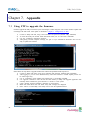
1
Eddy Serial User Guide Ver 2.5.3.1 2013.04.04 1 Revision History Revision Date Document Version Pages Description Feb-5-2009 2.1.0.1 All Initial release Sep-10-2009 2.1.0.2 4,5,6 Wi-Fi added Nov-11-2009 2.1.0.3 2,3,5 Eddy-S4M added Jun-06-2010 2.1.1.1 All Open Linux Version Eddy-BT added Sep-15-2010 2.5.1.1 2,5 Eddy-CPU v2.5 added Jan-20-2011 2.5.1.1 Eddy-S4M v2.5 added Feb-15-2011 2.5.1.1 Eddy-CPU/mp v2.5 added Aug-09-2011 2.5.1.1 Eddy-CPU/mp 32bit v2.5 added Dec-09-2011 2.5.1.1 Eddy-WiFi v3.0 added Apr-04-2013 2.5.3.1 Eddy New Firmware related added (Linux Kernel v2.6.30) 2 Table of Contents Chapter 1. Introduction..........................................................................................................5 1.1 About this manual .................................................................................................................... 5 1.2 Who should read this manual .................................................................................................... 5 1.3 Contents .................................................................................................................................. 5 1.4 Eddy Documents...................................................................................................................... 6 1.5 Technical Support .................................................................................................................... 6 Chapter 2. Getting Started .....................................................................................................8 2.1 Overview................................................................................................................................. 8 2.2 Eddy-CPU v2.5........................................................................................................................ 8 2.3 Eddy-DK v2.1 (Development Kit) ........................................................................................... 10 2.4 Eddy-S4M v2.5...................................................................................................................... 12 2.5 Eddy-S4M-DK v2.1 (Development Kit) .................................................................................. 14 2.6 Eddy-S4M-JIG v2.1 (Testing Board) ....................................................................................... 14 2.7 Eddy-WiFi v 3.0 .................................................................................................................... 16 2.8 Eddy-BT v2.1 ........................................................................................................................ 18 2.9 Eddy-CPU/mp v2.5 / 32bit v2.5 .............................................................................................. 19 2.10 Eddy Software Architecture .................................................................................................... 21 2.11 Main Features ........................................................................................................................ 21 2.12 Applications .......................................................................................................................... 21 Chapter 3. Hardware Description ........................................................................................23 3.1 Eddy-CPU v2.1/v2.5 .............................................................................................................. 23 3.2 Eddy-DK v2.1 ....................................................................................................................... 24 3.3 Eddy-S4M v2.5...................................................................................................................... 26 3.4 Eddy-S4M-DK v2.1 ............................................................................................................... 28 3.5 Eddy-S4M-JIG v2.1 ............................................................................................................... 29 3.6 Eddy WiFi v3.0 ...................................................................................................................... 30 3.7 Eddy BT v2.1 ........................................................................................................................ 31 3.8 Eddy-CPU/mp v2.5 / 32bit v2.5 .............................................................................................. 33 Chapter 4. Integration ..........................................................................................................34 3 4.1 Connection Guide .................................................................................................................. 34 4.2 First-time Booting up ............................................................................................................. 34 4.3 Connecting Eddy ................................................................................................................... 35 Chapter 5. Configuration via Web........................................................................................36 5.1 Connect to Web Manager........................................................................................................ 36 5.2 Network Settings ................................................................................................................... 37 5.3 Serial Settings ........................................................................................................................ 39 5.4 User File System .................................................................................................................... 42 5.5 Update Firmware ................................................................................................................... 43 5.6 Reboot .................................................................................................................................. 44 Chapter 6. Configuration via Telnet .....................................................................................45 6.1 Configure Telnet Client .......................................................................................................... 45 6.2 Connect ................................................................................................................................. 46 6.3 Check Current Configuration .................................................................................................. 47 6.4 Modify Configuration Values .................................................................................................. 48 6.5 Username/Password Commands ............................................................................................. 48 6.6 System Commands................................................................................................................. 48 Chapter 7. Appendix ............................................................................................................49 4 7.1 Using FTP to upgrade the firmware ......................................................................................... 49 7.2 Ordering Information ............................................................................................................. 50 7.3 FCC Statement....................................................................................................................... 51 Eddy User's Guide Chapter 1. Introduction Eddy, SystemBase Embedded Device Server Module, is an optimized minimal CPU module for developing an industrial embedded device. This manual introduces general functions for the Eddy. 1.1 About this manual This manual guides users to develop Eddy for a device server including the function that transfers from serial d ata to LAN. Setting Eddy’s configurations, status monitoring, firmware update, and other administration work ar e also included, H/W level integration and S/W setting information can also be found. 1.2 Who should read this manual This guide is designed for Eddy users and administrators. It is strongly recommended that anyone trying to app ly, use, and maintain Eddy read this document. It will be a great starting point for any administrator who want s to easily monitor and control Eddy and its connected devices. 1.3 Contents Chapter 1. Introduction is a preface with general information and introductory notices. Chapter 2. Getting Started gives a brief introduction to Eddy series, including features and applications. Chapter 3. Hardware Descriptions explains the layout and pin specifications with block diagram and drawings. Chapter 4. Configuration via Web provides ways to configure and to connect Eddy via web browser. Chapter 5. Configuration via Telnet provides commands and its explanation to configure and to connect Eddy v ia web Telnet. Chapter 6. Appendix provides firmware update guides and detailed technical specifications. 5 Eddy User's Guide 1.4 Eddy Documents The following table summarizes documents included in the Eddy document set. Document Description Eddy Serial User Guide Eddy’s Configuration, and Management Information Eddy DK Guide Programmer’s application development guide, including in-depth approach to compiling, linking, creating and uploading firmware API reference is included with a list of available functions for customized application programming LemonIDE User Guide User manual about Eddy integrated development environment of Window/Linux based on Eclipse PortView User Manual Guide for SystemBase device server management application PortView COM Port Redirector User Manual Guide for COM Port Redirector by SystemBase TestView User Manual Guide for test program, TestView, by SystemBase Other relevant documents are as follows: Document Description Eddy-CPU Spec Sheet Eddy-CPU spec description Eddy-S4M Spec Sheet Eddy-S4M spec description Eddy-WiFi Spec Sheet Eddy-WiFi spec description Eddy-BT Spec Sheet Eddy-BT spec description LemonIDE Spec Sheet integrated development environment description Eddy White Paper An introductory reading for anyone new to embedded device server, which focuses on background, history, market environment, and technology General information related to Eddy or embedded device servers can be obtained at Eddy Community at http:// www.embeddedmodule.com/. Latest documents, software and firmware are available. All documents are updated promptly, so check for the recent document updates. The contents in these documen ts are subject to change without a prior notice. 1.5 Technical Support You can reach our tech support by following 3 ways; 1. Visit the Eddy official community site at http://www.embeddedmodule.com and go to ‘Technical Support’ m 6 Eddy User's Guide enu. FAQ and questions can be reviewed and submitted. 2. Post your inquiries at our technical support website at http://www.solvline.com/ or e-mail our technical support tea m at [email protected]. Any kind of inquiries, requests, and comments are welcomed. 3. Call us at our customer center at +82-2-855-0501 for immediate support. Available from Monday to Friday, 09:00 to 18:00 KST (Korean Standard Time) Our technical support team will kindly help you get over with the problem. Copyright 2013 SystemBase Co., Ltd. All rights reserved. Homepage: http://www.sysbas.com/ Tel: +82-2-855-0501 Fax: +82-2-855-0580 16F Daerung Post Tower-1, 212-8, Guro-dong, Guro-gu, Seoul, Republic of Korea Postal code: 152-790 7 Eddy User's Guide Chapter 2. Getting Started This chapter includes Eddy series overview, main and distinctive features, package contents for each product, and application fields. 2.1 Overview There are two categories in Eddy; Eddy-CPU module, Eddy Development Kit (DK). Eddy-CPU modules include category of socket type Eddy-CPU and Mini PCI type Eddy-S4M. Eddy-DK includes DK board for Eddy-CPU exclusive, JIG and DK board for Eddy-S4M exclusive. The Eddy-CPU module includes default applications for serial and LAN communication, and supports plug-andplay features. By switching to the custom mode, users can program any application and upload it on to the mo dule. This application then is executed on the module. In order to write and compile programmer’s source code, Software Development Kit (SDK) LemonIDETM is required. SDK is included in the DK package. Please refer to Programming Guide and LemonIDETM user’s manual inclu ded in the Development Kit for detailed information on the SDK. SDK is not necessary for users using Eddy in default presetting. 2.2 Eddy-CPU v2.5 Eddy-CPU is an embedded module based on ARM9 processor with 32MB SDRAM, 4MB or 8MB Flash Me mory, 1 Ethernet port with 10/100Mbps, 16 bit address / 8 bit data bus interface supporting external device con nection, and maximum 17 programmable IO pins. Programmers can easily implement any device drivers with r eferring to library type example codes and evaluation kit circuit diagrams. User can design their own customized device using example sources and Evaluation Kit circuit. Eddy-CPU is implemented on a small form factor (42 * 25mm) with on-board memory and integrated 10/100 Mbps network interface. Developers can minimize time and cost spent on developing application products. 8 Eddy User's Guide Type Feature Eddy-CPU v 2.5 CPU Memory 19 Bit / 16 Bit Data Bus Ethernet I/F 10/100 Base-T Auto MDI/MDIX USB 2.0 FS ADC Software Environmental Approvals 9 4 Port, Support up to 921.6 Kbps (1 : Full Signal, 2,3,4, : RxD, TxD, RTS, CTS only) 2 Host /1 Device Port, 2.0 FS (12Mbps) 4-Channel 10 Bit ADC TWI(I2C) Master, Multi-Master and Slave Mode SPI 8- to 16-bit Programmable Data Length Four External Peripheral Chip Selects GPIO Network 8MB Data Flash, 32 MB SDRAM External I/F UARTs Hardware AT91SAM9G20 (400MHz) Max. 56 Programmable I/O Pins Power Input 3.3 V (Max. 200 mA) Dimensions 25 x 48.5 x 6.2 mm Weight 8.3 g Protocol TCP, UDP, Telnet, ICMP, DHCP, TFTP, HTTP, SNMP 1&2, SSH, SSL Ethernet Network Connection O/S Mgt Tools Uploads Dev Tools Operating Temp Storage Temp Humidity CE Class A, FCC Class A, RoHS compliant 10/100Mbps MAC / PHY Static IP, DHCP Linux Kernel 2.6.21 SNMP, Web, PortView TFTP, FTP, Web LemonIDE & SDK -40 ~ 85 ℃ -60 ~ 150 ℃ 5 ~ 95% Non-Condensing Eddy User's Guide 2.3 Eddy-DK v2.1/v2.5 (Development Kit) Eddy Development Kit (Eddy DK) helps programmers to test and customize their own Eddy applications easily. The kit includes evaluation board, all necessary connectors, and programming environment with documentation s and guidelines. Please refer to Eddy DK Manual included in the Development Kit for detailed information on the DK. Feature Type NAND Flash 256MB, 8bit I/F SD Card Connector Push Type, up to 16 GB MMC / SD Card / MC supported 1 x Device 2 x HOST, Dual-Port USB Connector 10 LCD Module 128 x 64 Dots Matrix Structure KEY Battery Holder LED 4 x 4 Matrix 3V Lithium Battery, 235 mAh Power, Ready, 20 Programmable IO, Console and Serial TxD, RxD I2C Interface 16bit I2C BUS GPIO SPI Interface 2Kbit EEPROM MCI Interface SD Card, MMC Socket ADC Interface Temp / Light Sensor Digital I/O 8 Port Input, 8 Port Output Eddy User's Guide Feature Switch Jumper Switch Serial Port Console Port LAN Port ICE Port Reset Button Input Power Dimensions 11 Type Serial or GPIO Select RS422/485 Select DIO : Common VCC or GND Select Programming Boot Mode Select, JTAG Select 2 x RS232 DB9 Male 2 x RS422/485 Terminal Block (RS422 or RS485 selected with S/W) DB9 Male 2 x RJ45 Used for Flash Programming Factory Default & Warm Boot 9-48VDC 240 x 180 mm Eddy User's Guide 2.4 Eddy-S4M v2.5 Eddy-S4M is a high-performance mini PCI type embedded module which include ARM9 processor 32MB SD RAM, 8MB DataFlash, 10/100Base-T Ethernet port, Serial 4 Channel, RTC with Battery, MicroSD, 4ch ADC, temperature sensor, max 34 programmable GPIO pins. Eddy-S4M is 59.75 x 61.8mm size. If using Eddy-S4M-JIG board, user could develop their customized device without other H/W development, which minimizing time and cost to develop. Referring Example code and Evaluation Kit circuit allow developer to design device they want. Hardware Eddy-S4M v2.5 is compatible with Eddy-S4M v2.1. The specification is as follows. Type Classification Eddy-S4M v2.5 CPU AT91SAM9G20 (400MHz) AT45DB642D, 8MB Data Flash Memory IS42S16160B, 32 MB SDRAM 10/100 Base-T MAC Ethernet MC/PHY KSZ8041NLi PHYceiver Auto MDI/MDIX Port 0,1 : RS232 (DB9 male) Port 0 : Full Signal Serials Port 1 : TxD, RxD, RTS, CTS only Port 2,3 : COMBO (Terminal Block 5pin) * COMBO : RS422/RS485 is S/W selectable 3 Host /1 Device Port, 2.0 FS (12Mbps) USB 2.0 FS Use to GL850A USB Hub chip Real Time Clock, RTC DS1340U-33+ RTC Connect to I2C I/F Battery Holder CR1220(38mAh) 3V Lithium Battery ADC 4-Channel 10 Bit ADC TWI(I2C) SPI MCI GPIO 12 Master, Multi-Master and Slave Mode 8 to 16-bit Programmable Data Length Four External Peripheral Chip Selects SD Spec V2.0 [SDHC], MMC Spec V4.2 support USB to SD Controller, 16GB, 12Mbits/s Max. 34 Programmable I/O Pins Eddy User's Guide Classification LED Protocol Software Physical characteristics Environment CE Class A, FCC Class A, RoHS compliant 13 Type Eddy-S4M v2.5 Ready LED TCP, UDP, Telnet, ICMP, DHCP, TFTP, HTTP, SNMP1&2, SSH, SSL Network Connection O/S Mgt Tools Uploads Dev Tools Linux Kernel 2.6.21 SNMP, Web, PortView TFTP, FTP, Web LemonIDE & SDK Power Input 3.3 V (200mA Max) Dimensions 59.75 x 61.80 x 4 mm Weight Operating Temp Storage Temp Humidity Static IP, DHCP 15 g -40 ~ 85°C -66 ~ 150°C 5 ~ 95% Non-Condensing Eddy User's Guide 2.5 Eddy-S4M-DK v2.1 (Development Kit) Eddy-S4M DK is Development Kit supporting programmer can easily materialize and test their application. DK includes Test Board, various connectors, programming environment and document. Please refer to Eddy-DK manual for more specific explanation of Eddy-S4M Classification MCI Interface Specification 2 x RS232 DB9 Male 2 x RS422/485 5pin Terminal Block (S/W Selectable & with Auto toggle) Push Type, Up to 16 GB MMC / SD Card / MC supported SD Card, MMC Socket ADC Interface Light Sensor USB Connector LAN Port Console Port 1 x Device, 2 x HOST, Dual-Port RJ45 with transformer DB9 Male Power ON/Off switch Serial RS422/485 Termination resistor configuration switch GPIO input test switch(Off : Low, ON : High) RDY, Power, 34 Programmable IO, Console & Serial TxD, RxD LED Used for downloading code and single-stepping through programs Factory Default & Warm Boot (If pushing over 5sec, operate in Factory default) Serial Port SD Card Connector Switch LED JTAG Port Reset Button JIG Connection Socket Expansion Header Input Power Dimensions 2 2x23pin socket, which connect to JIG board to check any problems 2x22pin Header, used to test GPIO of Eddy-S4M 5 VDC 160 x 120 mm 2.6 Eddy-S4M-JIG v2.1 (Testing Board) Eddy-S4M JIG board is test board which enable of user to integrate and test their application with Eddy-S4M. JIG board include mini connector for joining Eddy-S4M, Ethernet RJ45, USB Host, Power, Reset Switch, and 14 Eddy User's Guide providing connectors to all Eddy-S4M functions. For more information, please refer to Eddy-DK manual in DK product. Classification 15 Specification USB Connector USB HOST LAN Port Reset Button Expansion Header Input Power Dimensions RJ45 with Transformer Factory Default & Warm Boot Used to connect external devices with most functions of S4M 5 VDC 70 x 105 mm Eddy User's Guide 2.7 Eddy-WiFi v 3.0 (* Eddy-WiFi v2.1 is not compatible. please check the previous manual.) Eddy WiFi joined with Eddy-CPU v2.1/v2.5, Eddy-S4M v2.1 enables various serial devices (secure device, com munication device, modem, print data device, industrial measuring instrument) to connect wireless LAN. EddyWiFi module supports IEEE 802.11 b/g/n wireless specification. + Classification Standard Modulation Frequency Band Output Power RX sensitivity Security Working distance Data Rate Antenna Dimension 16 Specification 802.11b, 802.11g, 802.11n 802.11b:CCK, DQPSK, DBPSK 802.11g:64 QAM, 16 QAM, QPSK, BPSK 802.11n:BPSK, QPSK, 16-QAM, 64-QAM ISM band 2.4GHz ~ 2.4884GHz 802.11b:16 dBm (11Mbps) 802.11g:14 dBm (54Mbps) 802.11n:14 dBm (20MHz BW,MCS7) 13 dBm (40MHz BW,MCS7) 802.11b:-84dBm@11MHz 802.11g:-73dbm@54MHz 802.11n:-71dBm(MCS 7_HT20) -68dBm(MCS 15_HT20) -68dBm(MCS 7_HT40) -65dBm(MCS 15_HT40) WPA, WPA-PSK, WPA2, WPA2-PSK , WEP 64bit & 128bit , IEEE 802.11x, IEEE 802.11i 60 - 120m, depending on surrounding environment 802.11b: 11, 5.5, 2, 1 802.11g: 54, 48, 36, 24, 18, 12, 9, 6 802.11n: 20 MHz BW: 130, 1117, 104, 78, 65, 58.5, 52, 39, 26, 19.5, 13, 6.5 40 MHz BW: 270, 243, 216, 162, 150, 135, 121.5, 108, 81, 54, 40.5, 27, 13.5 (unit: Mbps) 2.4Ghz 2dB, 1 x U.FL 28.2 x 45.4 x 9.6 mm Eddy User's Guide Operating Temp -10 ~ 70°C Operating Voltages 3.3V±5% I/O supply voltage Weight 10g Approvals KC, RoHS Compliant LED Specification LED#2 Classification LED#1(TTXD) LED#2(TRXD) 17 LED#1 Specification When WiFi is connected, LED blinks. When WiFi is connected with other AP or device, LED blinks every seconds. When it is transmitting or receiving data, it will blink every 0.5 seconds. Eddy User's Guide 2.8 Eddy-BT v2.1 Linking to Eddy-CPU v2.1/v2.5 and Eddy-S4M v2.1, Eddy-BT module enables communication with various type s of Bluetooth device in Bluetooth method. Eddy-BT is based on Bluetooth 2.0 and supports communication dist ance of up to 100m. Classification Interface Bluetooth v2.0+ EDR Class 1 Profile SPP (Serial Port Profile) Max, TX Power +18dBm RX sensitivity -88dBm Operating Temp Supply voltage: 3.3V DC Supply current::10mA – 60mA Operating temperature: -30 ~ 80 oC Storage Temp Storage temperature: -40 ~ 85 oC Humidity Humidity : 90% (Non-condensing) Power Working distance Approvals 18 Specification Stub Antenna (+1dBi) - Stub Antenna (+1dBi) Stub Antenna (+1dBi) - Dipole Antenna (+3dBi) Dipole Antenna (+3dBi) - Dipole Antenna (+3dBi) Dipole Antenna (+3dBi) - Dipole Antenna (+5dBi) Dipole Antenna (+3dBi) - Patch Antenna (+9dBi) Dipole Antenna (+5dBi) - Dipole Antenna (+5dBi) Dipole Antenna (+5dBi) - Patch Antenna (+9dBi) Patch Antenna (+9dBi) - Patch Antenna (+9dBi) CE Class A, FCC Class A, RoHS Compliant 100 meters 150 meters 200 meters 300 meters 500 meters 400 meters 600 meters 1,000 meters Eddy User's Guide 2.9 Eddy-CPU/mp v2.5 /32bit Eddy-CPU is an embedded module based on ARM9 processor 4MB or 8MB Flash Memory, 1 Ethernet port with 10/100Mbps, 16 bit address / 8 bit data bus interface supporting external device connection, and maximum 17 programmable IO pins. Programmers can easily implement any device drivers with referring to library type example codes and evaluation kit circuit diagrams. Eddy-CPU/mp v2.5 is a low-cost mini PCI type module which is compatible with Eddy-CPU v2.5. DK provide s 32MB SDRAM, 64MB SDRAM and it is also compatible with DK v2.1 using its exclusive JIG board. Classification CPU Memory Ethernet I/F 10/100 Base-T Auto MDI/MDIX 4 Port, Support up to 921.6 Kbps (1 : Full Signal, 2,3,4, : RxD, TxD, RTS, CTS only) 2 Host /1 Device Port, 2.0 FS (12Mbps) 4-Channel 10 Bit ADC USB 2.0 FS ADC TWI(I2C) Master, Multi-Master and Slave Mode SPI 8- to 16-bit Programmable Data Length Four External Peripheral Chip Selects 3.3 V (200 mA Max) Dimensions 59.75 x 44.6 X 1.0 mm Protocol 19 Max. 56 Programmable I/O Pins Power Input Weight Software 8MB Data Flash, 32MB SDRAM, 64MB SDRAM 16 Bit / 16 Bit Data Bus GPIO Network AT91SAM9G20 (400 MHz) External I/F UARTs Hardware Specification Ethernet Network Connection O/S 8.3 g TCP, UDP, Telnet, ICMP, DHCP, TFTP, HTTP, SNMP 1&2, SSH, SSL 10/100Mbps MAC / PHY Static IP, DHCP Linux Kernel 2.6.21 Eddy User's Guide Classification Environmental Approvals 20 Mgt Tools Uploads Dev Tools Operating Temp Storage Temp Humidity CE Class A, FCC Class A, RoHS compliant Specification SNMP, Web, PortView TFTP, FTP, Web LemonIDE & SDK -40 ~ 85 ℃ -60 ~ 150 ℃ 5 ~ 95% Non-Condensing Eddy User's Guide 2.10 Eddy Software Architecture 2.11 Main Features Various features of Eddy make it a universal yet distinctive embedded solution. Below lists main features of Eddy. Premium-level hardware with ARM9 210MHz CPU, 8MB Flash, and 32MB SDRAM, 64MB SDRA M Selectable: RS232 only or RS422/485 Combo interfaces USB host port (Max. 8Mbps USB Full speed) MCI (Multimedia Interface) feature supported (Max. 8Mbps speed) Max 921.6Kbps serial communication speed Able to upload/run the user customized program SystemBase SDK and API support for application programming (included in the CD) Small size to fit in any hardware 10/100Mbps Ethernet port (auto MDIX) SystemBase COM Port Redirector for better adaptability Extensive configuration and monitoring with PortView Firmware upload with Web, FTP, and TFTP Configuration with Web, Telnet, SNMP, and PortView Various customizing options Standard Linux environment for openness in executable applications Multiple Programmable IO pins for customized applications Watchdog timer supported for monitoring the system and reset when system error is occurred. 2.12 Applications Eddy can be applied to many practical applications in various fields. Some are presented below. ◆ Factory / Industrial Automation 21 Eddy User's Guide PLC, Robot arms, Human-Machine Interface, Warehouse rails Medical instruments, Inspection equipment controllers Alarming units ◆ Home Appliances / Electronic Devices Power controller, Gaming machines Scales, Gas detection units, Water & pollution metering devices Data collection and distribution units ◆ Financial / Building Automation Card readers, Barcode scanners, Kiosks, Point-Of-Sale related devices Serial printers, Cash registers, Credit card authorization terminals Biometric detection units, Security devices ◆ OEM Device Server Distributors OEM device server with distributor’s own case & brand Ready-to-go device or customized application / setup mode can be inserted 22 Eddy User's Guide Chapter 3. Hardware Description This chapter provides Eddy’s hardware information, including block diagram, layout, pin specifications, dimensio ns and other hardware-related issues. 3.1 Eddy-CPU v2.1/v2.5 Ethernet port is provided as pin headers, and the transformer and RJ-45 connector should be manually impleme nted by users. (RJ-45 connector with embedded transformer, normally called LAN-Mate or MAG Jack, can be used as a simpler approach. Eddy CPU V2.1/v2.5 Device description Eddy CPU V2.1/v2.5 Connector description 23 Eddy User's Guide 3.2 Eddy-DK v2.1 It is Development Kit Providing environment to test and develop. Below shows simple instruction on device, s witch, pin, LED and so on. Switch Feature LED Feature 24 Eddy User's Guide External Device Feature A External Device Feature B 25 Eddy User's Guide Internal Device Feature 3.3 Eddy-S4M v2.5 Mini PCI Type Slot.. Eddy-S4M v2.5 is compatible with Eddy-S4M v2.1. When developing main board, user must materialize transformer and RJ-45 connector (or RJ45 in which transfo rmer is included (LAN-Mate or MAC Jack)). Since Driver IC is in Eddy-S4M, Serial port can be integrated ea sily only by attach connector. 26 Eddy User's Guide Eddy-S4M v2.5 27 Eddy User's Guide 3.4 Eddy-S4M-DK v2.1 Development Kit provides environment for testing and configuration for Eddy-S4M v2.1 28 Eddy User's Guide 3.5 Eddy-S4M-JIG v2.1 This is a test board to develop with Eddy-S4M v2.1 29 Eddy User's Guide 3.6 Eddy WiFi v3.0 Pin out for Eddy-WiFi module is introduced in this section. Antenna SMA Male Connector LEFT 30 Description RIGHT Description 1 NA 1 NA 2 NA 2 NA 3 NA 4 NA 5 VCC(3.3V) 6 VCC(3.3V) 7 USB Host Data(-) 8 USB Host Data(+) 9 NA 10 NA 11 H/W Reset 12 Ground 13 Ground 14 NA 15 NA 3 NA 16 NA 4 NA 17 NA 18 NA Eddy User's Guide 3.7 Eddy BT v2.1 Bluetooth module is composed to connect 4th serial port of Eddy-CPU or Eddy-S4M in TTL method. It is possib le to use Eddy-BT as 4th serial port, but it can lose data in case of using HW Flow Control. If you want to use HW Flow Control, please refer to Test_Bluetooth.c in SDK and revitalize HW Flow control of 4th serial port. 31 Eddy User's Guide 32 LEFT Description RIGHT Description 1 NA 1 NA 2 NA 2 NA 3 NA 3 NA 4 5 6 VCC(3.3V) Factory Reset UART TXD 4 5 6 NA VCC(3.3V) VCC(3.3V) 7 UART RXD 7 NA 8 UART RTS 8 NA 9 UART CTS 9 NA 10 Pairing Signal 10 NA 11 H/W Reset 11 H/W Reset 12 NA 12 Ground 13 NA 13 Ground 14 Ground 14 NA 15 Ground 15 NA 16 Ground 16 NA 17 NA 18 NA Eddy User's Guide 3.8 Eddy-CPU/mp v2.5 / 32bit v2.5 Ethernet port is provided as pin headers, and the transformer and RJ-45 connector should be manually impleme nted by users. (RJ-45 connector with embedded transformer, normally called LAN-Mate or MAG Jack, can be used as a simpler approach.) <Eddy-CPU/mp v2.5> <Eddy-CPU/mp 32bit v2.5> 33 Eddy User's Guide Chapter 4. Integration This chapter explains how you can make Eddy to communicate. It deals with LAN and pin header connection guides for Eddy to operate together with the target serial device. Follow these steps to connect Eddy to the device and network. 4.1 Connection Guide 1) WAN/LAN In order to connect Eddy to network, you need to use RJ45 Ethernet port. It supports both 10Mbps and 100M bps Ethernet connection (auto-sensing). Since Eddy’s LAN port supports MDIX function, you can either connec t cross LAN cable or direct LAN cable. Plug one end of a LAN cable to Eddy and the other end to a hub, s witch, or any other network device that can provide you with network access. 2) DB9 For the model included a DB9 serial port, you can simply connect Eddy to the destination serial device with a DB9 cable. For pin specifications, please refer to Chapter 3. 3) MCI slot MMC and SD Cards excepting T-Flash, Micro SD, and SDHC can be used through MCI slot. It provides Max imum 2 GBytes. Please note that MCI and SD Card must be inserted before power is induced to Eddy module. 2) USB Host An USB memory stick or USB hub can be attached to Eddy-S2M/PIN module’s USB host port. For an USB Hub it should have own power. 4.2 First-time Booting up First of all, please make sure the power input you supply to the module is corresponding with the Eddy model that you have. If an appropriate power input has been successfully supplied, Eddy will power on and start boo ting. Although there is no power LED to check the status, you can check by LEDs on the RJ45 Ethernet port. LED status operation is described in Chapter 3. Hardware Description. An IP address is required to access Eddy’s web interface or telnet command-line configuration tool. By factory default, Eddy is assigned a static IP address. After the initial connection, you can either manually assign a diff erent IP address or set Eddy to automatically get an IP address from a DHCP server. While this depends on y our network environment and policy, it is strongly recommended that you assign Eddy with a unique static IP. 34 Eddy User's Guide 4.3 Connecting Eddy In order to view current Eddy’s settings or modify them, you need to make a Web or Telnet connection to Ed dy. IP address is required information to make a connection. There are two ways you can know the current IP address of Eddy. First is to use a built-in, alias IP address of “10.10.1.1”. Second is to use “Detector” application provided in the Utility & Documents CD. This application allows searc hing for Eddy modules on the network. ◆ The factory default IP address: 192.168.0.223 Eddy’s default IP address is set to 192.168.0.223. In order to connect with this address, you need to change networ k configurations so that your PC can connect to the IP 19 2.168.0.223. Please refer to an example below, and note t hat values don’t necessarily have to be identical to the ex ample below. ◆ Factory default alias IP address: 10.10.1.1 In case you configure Eddy to use DHCP to obtain an IP address automatically, you might find it hard to know th e IP address to connect to. To provide users with an easi er way to know the current IP address, Eddy has a fixed alias IP that is always accessible. Use the address below whenever you cannot find out Eddy’s IP address. In order to connect with this address, you need to change network configurations so that your PC can connect to th e IP 10.10.1.1. Please refer to an example below, and not e that values do not necessarily have to be identical to the example below. Since Eddy-S4M doesn’t support LAN port so that do esn’t include below. 35 Eddy User's Guide Chapter 5. Configuration via Web 5.1 Connect to Web Manager Open your favorite web browser and enter the IP address of Eddy to access the web manager. 36 Eddy User's Guide 5.2 Network Settings You can manage the network environment settings in Network Settings. After changing values, you must click [Apply] button to apply the settings. Main features for WAN Setting is as follows. 37 Menu Default Descriptions Device Name Eddy Name of the current device Line Type Static IP IP obtaining method for network connection. IP Address 192.168.0.223 Subnet Mask 255.255.255.0 Current IP address Eddy is assigned to. (When line type is Static IP, manually enter an appropriate IP address. When line type is DHCP, current IP is displayed, but it is not editable.) Current subnet mask Eddy is assigned to. (When line type is Static IP, manually enter an appropriate subnet mask. When line type is DHCP, current subnet mask is displayed, but it is not editable.) Eddy User's Guide Gateway 192.168.0.254 Current default gateway Eddy is assigned to (When line type is Static IP, manually enter an appropriate default gateway. When line type is DHCP, current default gateway is displayed, but it is not editable.).. DNS 168.126.63.1 Domain Name Service IP address Main features for Network Service Setting is as follows. 38 Menu Default Telnet Service Enable FTP Service Enable WEB Service Enable Descriptions Set whether to enable the Telnet Server (If disabled, connection to Eddy using telnet is not possible.) Set whether to enable the FTP Server (If disabled, connection to Eddy using FTP is not possible.) Set whether to enable the Web Server (If disabled, connection to Eddy using a web browser is not possible.) Eddy User's Guide 5.3 Serial Settings You can set the communication and operation environment for the serial port. After changing values, you must click [Apply] button. If you do not save and exit, modified values will be lost. 39 Eddy User's Guide The serial settings for Eddy is as follows. Menu Default Descriptions Select the operation protocol, which the serial port would use. Disable Do not use this port. TCP Server Eddy works as a socket server, waiting for the client connection on the network. Socket number for awaiting connections can be set in ‘Local socket port’ field. All data between the socket and the serial port is transferred untouched after the socket connection is established. TCP Client Eddy acts as a socket client in this mode. It tries to connect to the server IP address and the socket number assigned when a certain server waits for connection on the network. All data between the socket and the serial port is transferred untouched after the socket connection is established. Operation Mode TCP Server TCP Broadcast Eddy works as a server, accepting up to 5 simultaneous connections from socket clients. Data transmitted from Eddy is broadcast to each socket client. TCP Multiplex Eddy works as a server, accepting up to 5 simultaneous connections from socket clients. The difference between TCP Broadcast and TCP Multiplex is that Multiplex allows each socket to communicate exclusively. That is, serial data in response are only transferred to the sender socket. UDP Server Eddy works as a UDP server, waiting for UDP connection from the client on the network. Socket number for awaiting connections can be set in [Local socket port] field. Once a UDP packet is received to the socket that waits for the connection, the data is transmitted to the serial port. The data input from the serial port is put into UDP packets, which eventually are sent to the client. UDP Client When the data is input to the serial port, UDP packets are sent using the preset IP address and the socket number of the server. Server IP and port number can be set in [Remote IP/Port]. Interface 40 RS232 Local Socket Port 4001 Port Alias Port1 User Application An executable file build by a user can be uploaded. The serial port 1 and 2 are fixed to RS232 so these ports cannot be selected. By selecting RS422 or RS485 (Echo, Non-echo) serial port 3 and 4 can be used. In Eddy-CPU, this can be selected by the dip switch S8 and S9 on EddyDK board, therefore this category cannot be selected. (option: RS422, RS485(Echo), RS485(Non-echo)) Set the socket number for the port. TCP server and UDP server operation mode make use of this port for awaiting network socket connections. Port alias name for convenience. (Max. 16 characters) Eddy User's Guide Menu Default Descriptions Baud Rate 9600 bps Set communication speed. (Options: 150, 300, 600, 1200, 2400, 4800, 9600, 19200, 38400, 57600, 115200, 230400, 460800, 921600 bps) Data Bits 8 Set the number of bits in each character size. (Options: 5, 6, 7, 8) Stop Bits 1 Set the number of stop bits. (Options: 1, 2) Parity None Set parity bit check scheme. (Options: None, Odd, Even) Flow Control None Device Type DataOnly Remote IP Address / Port 0.0.0.0 / 4000 Set the flow control scheme. (Options: None, Xon/Xoff, RTS/CTS) Set the signal line checking method for the device to be connected to the given serial port. If the mode is set to Data Only, only TxD, RxD, and GND signal lines are used in inter-device communication. If the mode is set to Modem Signals, all modem signals except RI (Ring Indicator) are asserted, tested, and used in communication. (Options: Data Only, Modem Signals) While in TCP Client or UDP Client mode, set the target IP address and the port number. After a certain amount of time passes without any communication after the socket connection between the given serial port and the server are established, automatically disconnect the socket connection. (Valid from 0 to 32767 sec. When set to 0, it is disabled.) Keepalive Check Time 0 For example, if the operation mode is set to TCP Server and Alive Check Time is configured to 10, TCP Server will listen for the client’s connection and eventually establish a connection. Since the check time is 10 seconds, the server will wait for 10 seconds until the client connected to it sends any packet. If there is no data for 10 seconds, server will quit the connection and return to the listening state. This option is helpful in preventing communication obstacles that occur when either Eddy or the client quits unexpectedly (i.e. Sudden black out, reboot, LAN cable cut, etc.). In these cases, the other part of communication might not recognize the failure of its partner. Such misunderstanding can cause communication errors. If the value is set to 0, this function is disabled. Once connected socket will be retained until explicitly disconnected. Latency Time 41 0 (Only applies to TCP Client, TCP Server, TCP Broadcast, and TCP Multiplex operation modes.) This needs to be set when consecutive data from the given serial port needs to be transmitted to socket at once. For example, if 100 bytes of character string are to be transmitted from the serial device to a server through Eddy, bypass is set to 0 for the latency time. Although it provides immediate sending through Eddy, the server could be received a lot parts of divided packets. If the latency time is not 0, Eddy will wait for the time and check new data. If there is new data, Eddy repeatedly wait for the time. Otherwise, Eddy will transfer the buffered data, but it could not run in real time. Eddy User's Guide 5.4 User File System When a user uploads a customized user file system, it will be automatically executed when Eddy boots. The user can add or remove and features for his/her needs. From the [Upload] shown in image below, use the [Browse] button to upload the file which then will be added to [Zip File List] with its path shown in the left. The text box to the right is where zipped file will be unzipped when Eddy boots. Zipped file system is usually set to unzip to /. If the delete button is clicked, the file in /flash will be removed and when Eddy boots again, removed file system will not be applied. 42 Eddy User's Guide 5.5 Update Firmware Firmware is an application embedded in flash memory. Set the location of the firmware file to update, using th e [Browse…] button. The selected firmware will be sent to Eddy when you click [Update] button. After the up loading is complete, it will take about 60 seconds to save the new firmware to the flash memory. Then, Eddy will automatically restarted to run with the new firmware. 43 Eddy User's Guide 5.6 Reboot Reboot Eddy from the Reboot menu in the left. 44 Eddy User's Guide Chapter 6. Configuration via Telnet 6.1 Configure Telnet Client In Windows XP, telnet is provided by default, but in Windows 7 and 8, as shown below, telnet is not availabl e right away. Please use the following steps to install the telnet client. Control Panel Programs Turn Windows features on or off Telnet Client Click and add a check mark next to the telnet client and click ok to install the telnet service. 1 2 3 When the installation is complete, use telnet to connect to Eddy. 45 Eddy User's Guide 6.2 Connect When you connect to Eddy, it will ask for the login ID and password. Use the information below to login. The login ID and password for the telnet are the same for the web connection. ◆ Factory Default user ID ◆ Factory Default password : eddy : 99999999 setenv command - Set the settings for Eddy After the settings are modified, printenv command can be used to check the changed value. However, unless the saveenv command is used, the settings will valid until Eddy reboots. 46 Eddy User's Guide 6.3 Check Current Configuration To check all the settings, use /usr/bin/printenv command. Usage : printenv To check an individual setting value use /usr/bin/getenv command. Usage : getenv <variable> Example : getenv ipaddr Environmental Value product firmware ipaddr netmask serverip ethaddr gatewayip baudrate stdin stdout stderr ethact httpd ftpd telnetd userinit dhcpd dhcpstart dhcpend dhcplease lanip lansubmask dnsip wifi wifimode wifissid wifipassword wifichannel wifiauthmode serial01 serial02 serial03 serial04 47 Description Product Name Firmware Version IP Address Network mask TFTP Server IP Address Network Hardware(MAC) Address Gateway IP Address Debug Serial Port Speed Standard Input (bootloader only) Standard Output (bootloader only) Standard Error (bootloader only) Ethernet Device Name (bootloader only) Web Daemon Execution Status (y/n) FTP Daemon Execution Status (y/n) TELNET Daemon Execution Status (y/n) User initialization command DHCP Daemon Execution Status (y/n) DHCP Service First Address DHCP Service Last Address DHCP Service lease time (unit in seconds) LAN port IP Address LAN port subnet mask DNS server Address WIFI usage status (y/n) WIFI operation mode (normal/adhoc) SSID of the wireless AP to connect Password/Passkey of the wireless AP Channel number (1~13) to be used to connect while in adhoc mode WIFI adhoc authentication mode (open/shared) Parameter of Serial 1 Parameter of Serial 2 Parameter of Serial 3 Parameter of Serial 4 Default Value Eddy v2.5 2.5.2.0 192.168.0.223 255.255.255.0 192.168.0.220 00:05:f4:00:20:57 192.168.0.254 115200 serial serial serial macb0 y y y /flash/userinit.sh n 10.10.1.2 10.10.1.10 864000 10.10.1.1 255.255.255.0 168.126.63.1 n normal - Eddy User's Guide 6.4 Modify Configuration Values To set the specific setting, use /usr/bin/setenv command. Usage : setenv <variable name> <value> Example : setenv ipaddr 192.168.0.220 6.5 Username/Password Commands Configure username and password for Web/Telnet/FTP. Commands Default Descriptions setenv username <username> eddy Set username to use in Web, Telnet, or FTP. (Max. 16 characters) setenv password <password> 99999999 Set password to use in Web, Telnet, or FTP. (Max. 16 characters) 6.6 System Commands Commands Descriptions setenv default Restore all settings to factory default. Requires reboot for changes to take an effect. saveenv reboot 48 Save current configuration settings. Requires reboot for changes to take effect. Reboot Eddy. Eddy User's Guide Chapter 7. Appendix 7.1 Using FTP to upgrade the firmware Firmware upgrade for Eddy can be done by the web manager or telnet using FTP. This section describes update meth od through FTP and Telnet. Web update is described in Chapter 5. Configuration via Web. 1) 2) 3) 4) Connect to Eddy with FTP, using correct username and password. (Default: eddy, 99999999) To check the binary file transfer mode and transfer status, use ‘bi’ and ‘hash’ commands. Use ‘put’ command to upload the firmware. After getting ‘Transfer complete’ message, use ‘quit’ or ‘bye’ command to disconnect. Now we are r eady to update the firmware. Please follow the steps below to upgrade the firmware with the file uploaded with the steps above. 1) Connect to Eddy with telnet, using correct username and password. (Default: eddy, 99999999) 2) After logging in, you are in the default directory where the firmware is located. Update process can be started right away. 3) Use ‘ls’ command to check whether the firmware file is successfully uploaded. 4) Use ‘upgrade’ command to write this file into flash memory in Eddy. The Upgrade Application auto matically detects whether the given firmware is a kernel or a file system. 5) Usage: upgrade <firmware filename> (Filename is case-sensitive.) 6) Make sure ‘Flash Write OK’ and ‘Flash Verify OK’ messages are displayed. 7) Enter ‘reboot’ to restart Eddy. Now Eddy will run with the updated firmware. 49 Eddy User's Guide 7.2 Ordering Information Product Description Eddy-CPU 2.1 Embedded CPU Module Eddy-CPU 2.5 Embedded CPU Module Eddy-CPU 2.5B Eddy-DK 2.1 Eddy Development Kit with Eddy-CPU v2.1 Eddy-DK 2.5 Eddy Development Kit with Eddy-CPU v2.5 Eddy-DK 2.5B Eddy Development Kit with Eddy-CPU v2.5 (64MB SDRAM) Eddy-S4M 2.1 Embedded CPU Module (Mini PCI Type) Eddy-S4M 2.5 Embedded CPU Module (Mini PCI Type) Eddy-S4M-DK 2.1 Eddy-S4M v2.1 Development Kit Eddy-S4M-JIG 2.1 Eddy-S4M v2.1 JIG Board Eddy-WiFi 3.0 802.11 b/g/n Wi-Fi Module Eddy-BT 2.1 Bluetooth 2.0 Module Eddy-CPU/mp 2.5 Embedded CPU Module (32MB SDRAM) 2.5B Embedded CPU Module (64MB SDRAM) Eddy-CPU/mp 32bit Eddy-CPU/mp-JIG 50 Version 2.5 Embedded CPU Module (64MB SDRAM) Eddy-CPU/mp v2.5 JIG Board Eddy User's Guide 7.3 FCC Statement THIS DEVICE COMPLIES WITH PART 15 OF THE FCC FULES. OPERATION IS SUBJECT TO THE FOLLOWING TWO CONDITIONS: 1) THIS DEVICE MAY NOT CAUSE HARMFUL INTERFERENCE. 2) THIS DEVICE MUST ACCEPT ANY INTERFERENCE RECEIVED. 3) INCLUDING INTERFERENCE THAT MAY CAUSE UNDESIRED OPERATION. FCC RF INTERFERENCE STATEMENT NOTE: This equipment has been tested and found to comply with the limits for a Class A digital device, pursuant to p art 15 of the FCC Rules. These limits are designed to provide reasonable protection against harmful interferenc e when the equipment is operated in a commercial environment. This equipment generates, uses, and can radiat e radio frequency energy and, if not installed and used in accordance with the instruction manual, may cause h armful interference to radio communications. Operation of this equipment in a residential area is likely to cause harmful interference in which case the user will be required to correct the interference at his own expense. 51