1
December 2013, Volume 15, No. 12
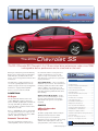
The 2014
Chevrolet SS
The 2014 Chevrolet SS, Chevrolet’s first V8 rear-wheel-drive performance sedan since 1996,
is designed to deliver performance on the street and on the track.
Sharing its underpinnings with the Camaro,
Caprice Police Patrol Vehicle and Holden’s
VF Commodore, the SS benefits from a
proven, race-tested, global rear-wheel drive
architecture.
the shift knob and the steering wheel. It
includes a transmission oil cooler. The
engine’s torque is channeled to the rear
axle, which has a 3.27 ratio for a great feeling of performance.
The SS features a high performance version of the legendary Chevrolet 6.2L V8
small block engine and a 6-speed automatic
transmission equipped with TapShift®.
Sport Shift mode – can be selected for
maximum responsiveness. The transmission
will delay upshifts and allow earlier downshifts. In addition, the transmission can
sense enthusiastic driving, at which point it
may delay upshifting and downshift earlier
when braking.
Here’s a closer look at the new SS.
POWERTRAIN
V8 Engine
The all-aluminum small-block 6.2L V8
engine (RPO LS3) produces 415 horsepower (310 kW) @ 5900 rpm and 415 lb.-ft.
of torque (563 Nm) @ 4600 rpm, which
propels the SS to a 0-60 acceleration time
of about five seconds.
dexos 1™ SAE 5W-30 is the recommended
viscosity grade for the 6.2L engine. Do not
use other viscosity grade oils such as SAE
10W-30, 10W-40, or 20W-50.
Automatic Transmission
The 6-speed automatic transmission includes TapShift controls located on both
Active Select (A/S) mode – allows
gears to be selected manually. It can also
provide engine braking by selecting the
appropriate lower gear on a steep downhill grade.
CHASSIS
Contents
2014 Chevrolet SS . . . . . . . . . . . . . . . . . . . . . . . . . . . 1
New Service Information Text and Graphics. . . . . . . . 1
Submit a Field Product Report . . . . . . . . . . . . . . . . . . 4
Corvette Driveline Support Alignment . . . . . . . . . . . . 4
Rough Idle Condition. . . . . . . . . . . . . . . . . . . . . . . . . . 4
Test Probe and Terminal Release Tool Kits. . . . . . . . . 5
Corvette Tire Chatter. . . . . . . . . . . . . . . . . . . . . . . . . 6
Rear Brake Noise on First Apply. . . . . . . . . . . . . . . . . 6
Power Liftgate Inoperative . . . . . . . . . . . . . . . . . . . . . 6
Cylinder Out-of-Round Diagnosis . . . . . . . . . . . . . . . . 7
Molding Retainer Bolt Corrosion. . . . . . . . . . . . . . . . . 7
Electric Cup Holder Cover Operation . . . . . . . . . . . . . 7
4-Wheel Independent
Suspension
Inoperative Spark EV Air Conditioning . . . . . . . . . . . . 7
The SS is equipped with 4-wheel independent Sport-Tuned suspension (FE3).
Heated/Cooled Seat Operation during Remote Start. 8
The front suspension is a multi-link
MacPherson strut setup with a direct-acting
stabilizer bar and progressive-rate coil
springs. Camber, caster and toe are fully
Car Issues – Fix It Right the First Time. . . . . . . . . . . . 9
continued on page 2
Revised Operation of Hazard Switch. . . . . . . . . . . . . . 8
Buzzing Noise at Right Front Wheel. . . . . . . . . . . . . . 8
Service Know-How . . . . . . . . . . . . . . . . . . . . . . . . . . . 8
Truck Issues – Fix It Right the First Time. . . . . . . . . . . 9
Customer Care and Aftersales
The 2014 Chevrolet SS –
adjustable. A hydraulically damped bushing is used on the forward end of the tension link for improved ride isolation.
The rear suspension is a multi-link independent system with progressive-rate coil
springs over shocks; decoupled stabilizer
bar and fully adjustable camber and toe.
High lateral stiffness for handling is provided by three lateral ball joints per side
with improved longitudinal compliance. A
rubber isolated suspension frame isolates
the body from road imperfections and
drivetrain vibrations.
Electric Power Steering
The Electric Power Steering (EPS) system
uses a forward-mounted steering rack.
The variable-effort electric power-assisted
rack-and-pinion steering is calibrated to
detect constant driver steering wheel load
due to factors such as road camber and
crosswind. The system will compensate to
reduce steering effort to a more neutral
level and lessen potential driver fatigue.
continued from page 1
Depending on equipment, the SS may
come with a full size 245/40ZR19 spare
tire that is the size that comes as original
equipment on the front of the vehicle.
If a flat tire occurs on the rear of the
vehicle and the spare tire is installed, a
275/35ZR19 tire must be installed on the
rear of the vehicle as soon as possible.
CONVENIENCE AND
ENTERTAINMENT
MyLink Infotainment System
The Chevrolet MyLink infotainment system
is standard on the SS and is accessed
via an 8-inch (203 mm) diagonal color
touch screen housed in the center stack.
Brembo Brakes
Standard front Brembo aluminum 4-piston
calipers operate on ventilated 14-inch
(355-mm) two-piece rotors. Solid 12.7inch (324-mm) rotors are used at the rear.
The Brembo aluminum brake calipers provide increased stiffness to reduce fluid displacement and caliper deformation without
adding weight, reducing brake wear and
providing superior braking performance.
Electronic Brake Force Distribution
optimizes control of rear brake pressure
on all road surfaces and under all vehicle
loading conditions.
Electronic Brake Assist senses how hard
and fast a driver depresses the brake
pedal and gives extra braking assistance,
if required.
High-Performance Tires
The SS uses ultra-high-performance
summer-only Bridgestone tires —
245/40ZR19 on the front, mounted on
19 x 8.5-inch polished forged aluminum
alloy wheels and 275/35ZR19 on the rear,
mounted on 19 x 9-inch polished forged
aluminum alloy wheels. The different size
front and rear tires should not be rotated
front to rear. Rotate the tires in a side-toside rotation pattern only.
TIP: Summer performance tires should
not be used for driving in winter conditions. Doing so will adversely affect safety
and performance.
Standard MyLink system
The system features a Bose® 220-watt,
9-speaker premium sound system including
subwoofers, a CD player and navigation.
Standard Automatic Parking
Assist
SS is the first Chevrolet to offer Automatic Parking Assist, which provides
hands-free parking help. The system uses
an ultrasonic sensing system to detect
the width and depth of either parallel or
reverse right-angle parking spaces. While
the driver controls the throttle, transmission and brake, Automatic Parking Assist
controls the steering input necessary to
park the vehicle.
When activated, the system searches for
parking spaces to the right of the vehicle.
To search for a parking space to the left,
turn on the left turn signal.
If the vehicle is in R (Reverse), but does
not steer into the expected space, the system may be maneuvering the vehicle into
a previously detected space.
ELECTRICAL ARCHITECTURE
The 2014 SS uses GM’s Global A electrical architecture, which requires the use
of the Global Diagnostic System 2 (GDS
2) software and the Multiple Diagnostic
Interface (MDI) module.
Because the Chevrolet SS is built in
Australia, the navigation path used to
select the vehicle when using SPS to
2
r eprogram a control module is slightly
different. Follow these steps:
1. In the Service Programming System
– Validate/Select Vehicle Data – Salesmake screen, select the drop down menu.
2. Scroll down the menu until Chevrolet
Holden appears.
3. Select Chevrolet Holden.
SAFETY AND CRASH
AVOIDANCE
Forward Collision Alert is standard and
uses a digital camera to help drivers avoid
front-end collisions. It is a warning system
only and does not apply the brakes.
The high-resolution digital camera is
mounted on the windshield, ahead of the
rear view mirror. The system looks for
vehicles ahead and uses the vehicle’s
Head-Up Display (HUD) to warn drivers
if they are following another vehicle too
closely. The system detects vehicles within
a distance of approximately 197 ft (60 m)
and operates at speeds above 25 mph
(40 km/h).
Lane Departure Warning is a camerabased lane detection system that uses a
camera sensor mounted on the windshield
ahead of the rearview mirror to detect the
lane markings. It warns the driver of unintentional lane departures if the vehicle is
crossing a lane without using a turn signal.
Side Blind Zone Alert uses radar sensors
on both sides of the vehicle to look for
other vehicles in the side blind zone areas
and indicates their presence with LED-lit
symbols in the outside mirrors.
Rear Cross Traffic Alert uses the same
sensors as the Side Blind Zone Alert
system to warn drivers of approaching
vehicles when backing out of a parking
spot, including angled parking. Visual
and audible alerts are triggered if moving
vehicles are detected.
TOWING
The 2014 SS was neither designed nor
intended to be towed with any of its
wheels on the ground. If the vehicle must
be towed, use a flatbed car carrier.
There are two oval-shaped slots under the
front of the vehicle that should be used to
move a disabled vehicle. To hook to the
vehicle, use only these slots. The slots can
be accessed through the splash shield.
Use an appropriate size T-hook for the
slot. Use the proper nylon strap harnesses
around the tires to secure the vehicle on
the flatbed carrier.
continued on page 3
December 2013
New Service Information Text Formats and Graphics
The Service Information is getting a new
look in 2014. When referring to some repair
procedures, technicians will notice better
graphics and more direct text information
along with a reduction in the number of
links to removal procedures. The implementation of these graphics and text will start
with the 2014 model year, and there will
be a mix of the new and old styles as new
procedures are written.
An X in brackets indicates the
number of parts
New Graphics
Newly developed graphics are replacing
the current line style graphics in some service procedures. The new, larger shaded
graphics feature a more realistic image
with better part and background definition.
The callouts are captured inside the
graphic image.
Graphics will feature three shadings:
Part – darkest grey shading
Background – lighter grey shading
Fasteners – red
Graphics and text can be magnified
without any loss in resolution.
Text Strings
Text strings are being introduced in the
Service Information procedures in an effort
to increase consistency and commonize
global phrases. The text strings are common, predefined, fixed phrases.
Two styles of text strings will be used in
service information:
•Sentence Text Strings are used when
frequently used procedure steps require
additional explanation. They are complete sentences that contain the necessary elements to describe an action or
a fact. For example: [Apply grease to
the fastener, otherwise the threads will
strip out.]
Text string usage is currently being implemented for Mechanical Service Information
only. Electrical Service Information text
string usage is still under development and
will be implemented in the future. Both text
string styles may appear in the same service procedure along with free flow text.
•Chained (Component) Text Strings
contain a component name and an action
verb. They are used when little explanation is required to complete the step. For
example: [Engine Control Module ][»]
[Remove ]
The part is now colored dark gray and
fasteners are colored red.
The use of color on fasteners will help them
stand out, while still being able to print
clearly in black and white.
The @ symbol means “from the”
or “to the”
In a procedure with text strings:
The higher resolution graphics also have
better graphic quality when magnified.
When viewing the Service Information on
Internet Explorer 8 or 9, use the % button
in the bottom right corner to increase text
size without distorting the graphic quality.
•A chevron (») is followed by the action verb
•An X in brackets indicates the number of
parts to remove/install
•RPO codes or optional equipment are
shown in brackets {RPO}
•An @ symbol is used where “from the”
or “to the” was used before.
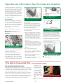
The 2014 Chevrolet SS –
PRE-DELIVERY INSPECTION (PDI)
The factory-installed shipping spacers in the front coil springs provide additional clearance during vehicle transportation and MUST
be removed when performing the PDI. With the vehicle on a hoist,
remove the shipping spacer and repeat for the other side.
The factory-installed rear disc brake rotor protection covers also
MUST be removed when performing the PDI. With the vehicle on
a hoist, rotate the wheel while at the same time pulling the torn
end of the cover away from the disc brake rotor and wheel. Ensure
that all material is removed and repeat for the other side.
More concise new style text
Thanks to Bob Scherer, Kevin Jakobiak
and Peter Allen
continued from page 2
In addition, check
the tire air pressure
during PDI. The pressures are set higher
for shipping. The tires
pressure should be
set at 36 lbs. Refer
to the Tire and Loading Information Label
near the driver’s door
latch.
Remove the spacer in the front springs.
Thanks to Brad Thacher and Sherman Dixon
December 2013
3
Corvette Driveline
Support Alignment
When and How
to Submit a Field
Product Report
If the driveline support (torque tube) is removed from the 2014
Corvette for any reason, special care must be taken to make sure
the propeller shaft splines are in alignment with the front hub
bearing. The Driveline Support must be aligned with the engine
bell housing before attempting to tighten any attachment bolts.
The information submitted by technicians in Field Product
Reports is a critical part of the product problem resolution
process. The details provided on timely issues affecting new
vehicles, e
specially during the launch of new models, help in
identifying and addressing all types of conditions.
TIP: The propeller input shaft front bearing positioning system
is designed to withstand an insertion force of no more than 582 Y
(130 lb). If the fastening bolts are used as an installation method,
it may create force above this amount and damage the crankshaft
thrust bearing.
3 Critical Points
When considering when to submit a report, determine if it
meets the following three critical points.
When
reinstalling the
driveline
support,
the angle
may be
slightly
off horizontally
or vertically.
This can
Automatic transmission driveline support.
make the
driveline
support
difficult to align. Do not use the bell housing attachment bolts
to draw the driveline support tight against the bell housing. Any
small amount of misalignment may cause the input splines of the
propeller shaft to catch on the crankshaft, driving it forward. If
the engine is started in this condition, it may cause the crankshaft thrust bearing to be immediately worn, necessitating engine
replacement.
Critical Product Concern – Safety concern, no start,
walk-home condition
Critical Timing – Safety concern, vehicle in dealership, plant
build concern
Critical Information – More details, including photos or
videos to better understand a condition
Field Product Reports can be helpful in communicating a number
of conditions, such as wiring harness routing damage (submitted
with photos), repetitive repairs not addressed by a Bulletin or
PI, or significant issues not covered under warranty (including
conditions considered normal operation or found during PDI).
Keep in mind that issues with the Service Information, Bulletin information and Labor Times should be addressed through
Service Information Feedback, not a Field Product Report.
New App
The new Field Product
Report application
makes it easier and
more convenient to
create and submit a report. The new app, GM
Field Product Report, is
free and can be found
on the app stores for
Android and Apple
devices.
Refer to the appropriate Service Information for complete procedures on alignment and installation of the driveline support to
ensure that the propeller shaft is properly aligned to the front hub
bearing.
Thanks to Gary Kirrkamm
To use the new app,
simply download it to
your mobile device
and log in using your
GlobalConnect ID and
password (user profile
New Field Product Report app for
information must be
Android and Apple devices.
filled out on the initial
use), and then start filling out the required fields. You can also include up to six photos
or up to 30 seconds of video.
Rough Idle Condition
Some 2013-2014 ATS models equipped with the 2.5L engine
(RPO LCV) may have a rough idle when the engine is at operating
temperature. The roughness is usually noticed through the seat of
the vehicle.
Updated software calibrations are available on TIS2Web to
address this condition. For 2013 models, reprogram the Engine
Control Module (ECM) and the Fuel Pump Control Module
(FPCM). For 2014 models, reprogram the ECM and the Chassis
Control Module (CCM).
In addition to the Field Product Report app, reports can still
be submitted via email. Fill out the form located on GM GlobalConnect > Service Workbench > Service Forms and email it to
[email protected].
Each module must be programmed separately, not sequentially.
Contact the Techline Customer Support Center (TCSC) at
1-800-828-6860 (English) or 1-800-503-3222 (French) for
programming instructions.
For more information about the Field Product Report
process, refer to Bulletin #02-00-89-002L (U.S.) or Bulletin
#10-00-89-006 (Canada).
Thanks to Mark Gordon
Thanks to Ray Romeo
4
December 2013
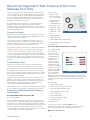
Electrical Diagnostic Test Probe and Terminal
Release Tool Kits
Electrical terminals are critical to the operation of all electrical
circuits. Terminals are quite reliable. But, because they are small,
precision-made components, terminals may be damaged by improper assembly and disassembly, improper testing, corrosion
or use of non-GM-approved service tools. If a terminal becomes
damaged, it may have to be replaced.
Bosch Automotive Service Solutions is presently offering two
GM-approved test probe and terminal release (pick) kits —
containing only the most frequently used tools — at discounted
pre-order pricing until December 31, 2013. Products will be available during February 2014.
Terminal Test Probes
When testing an electrical terminal, insert a test probe into the
terminal, then touch the Digital Multimeter (DMM) probe to the
open back side of the test probe.
Never touch the probes of a DMM to a terminal, either in an
electrical harness or on a component. The mating surfaces of the
terminal could be deformed or otherwise damaged. This could
result in poor retention or a poor electrical connection.
Test probes are made in a variety of sizes, both male and female.
Mating terminal probes are color coded for quick identification.
To test an electrical circuit that is carrying current, unplug the
connector, and then insert matching male and female test probes
into the corresponding circuit terminals. Join the test probes with
the appropriate jumper cable to complete the circuit. Then perform the test by applying the DMM probe to the back side of the
test probe.
Terminal Release Tools
When it is necessary to remove an electrical terminal from a
connector, use the appropriate terminal release tool, or pick.
A small lock tang retains the terminal in the matching connector
by engaging a lock shoulder in the connector. It is necessary to
depress the lock tang to slide the terminal out. There is a canal in
the connector to permit installing the appropriate terminal release
tool to depress the lock tang.
Many connector pairs use a Connector Position Assurance lock
(CPA) to ensure that the connector halves remain together. A
CPA cannot be installed until the connector halves are properly
mated. And once the CPA is installed, the connector halves
cannot be disassembled until the CPA is removed.
The kit includes:
•963716-2-PKG
Micro .64 Terminal
Test Lead Package
•J-35616-64B - Blue
Male Micro .64
•J-35616-65B - Blue
Female Micro .64
•J-35616-35 - Purple
•J-35616-14 - Green
•J-35616-16 - Light
Green
Terminal Test Probe Kit
•J-35616-2A - Gray
•J-35616-4A - Pink
•J-35616-20W - White Jumper Cable
•J-35616-20G - Green Jumper Cable
•Storage Pouch
EL-38125-300 Terminal Release Tool Kit
Price: $98.60 (USD)
Bosch J-38125
Terminal Picks (release tools) are the
only GM-approved
products to remove
terminals from
connector bodies.
Engineered to GM
specifications, these
tools will not damage
terminals or harnesses
during service. Other
terminal removal deTerminal Release Tool Kit
vices and methods
that do not meet
GM-approved specifications may cause damage to terminals and
wiring harnesses. The Pick kit contains only the most popular tools
that are required to service the majority of current GM vehicles
globally.
The kit includes:
•J-38125-11A Dark Blue
Many terminals also use a Terminal Position Assurance lock (TPA)
to ensure that the terminal remains installed into the connector.
•J-38125-12A Light Transparent Green
Terminal Test Probe Kit and Terminal Release
Tool Kit Offers
•J-38125-553 Black “Chisel Point”
•J-38125-21 Red Delphi Micro 0.64
•J-38125-216 Brown
EL-35616-300 Terminal Test Probe Kit
•J-38125-215A Purple
Price: $73.35 (USD)
•J-38125-213 Gray Micro 0.64
Bosch J-35616 Terminal Probes are the tools of choice for wiring and electronic component diagnosis. They are GM approved
and engineered to support proper diagnosis and will not damage
terminals or harnesses. The EL-35616-300 Probe Kit includes only
the most popular probes and components that are required to
service 80-90% of current GM vehicles globally. It is a less expensive option than the complete J-35616-F kit.
•J-38125-561 White
December 2013
•Storage Pouch
To order either kit, call 1-800-GM-TOOLS or visit
gmspecialservicetools.service-solutions.com. Purchase two or
more of each kit and receive an additional 5% discount.
Thanks to Chuck Berecz
5
Rear Brake Noise on
First Apply
Corvette Tire Chatter
The Corvette always has been built to perform. Part of the ride and
handling equation is the high-performance tires available on recent
Corvettes.
The 2014 Corvette is equipped with standard P245/40ZR18 front
and P285/35ZR19 rear performance summer-only tires and the Z51
Performance Package includes P245/35ZR19 front and P285/30ZR20
rear Michelin Pilot Super Sport ZP summer-only tires. These tires may
have a chatter noise during
low speed turns.
On some 2013 Encore AWD and Trax AWD (Canada
only) models, after the vehicle is first started, a rear
brake noise may occur during the first time the brakes are
applied when backing up. The noise also may occur the
first time the brakes are applied with the vehicle in Drive.
The vehicle may have been sitting only a few hours or
overnight.
The tread design of the
Goodyear F1 tires on the
2011-2013 Corvette Grand
Sport and Z06 models also
is more susceptible to tire
chatter or hop than the
tread design on previous
F1 tires.
Tire chatter noise, caused
by the large amount of tire
scrubbing across the pavement, occurs most often
during low speed, tight
turns (in all directions)
when the tires are cool,
usually after an extensive ambient soak of the vehicle. The chatter
typically diminishes when the tires warm up, but may increase on wet
pavement. This is a normal characteristic of the high-performance tires.
It’s important not to confuse a tire chatter condition with a possible
rear differential chatter noise.
A vehicle soak of at least eight hours during cool ambient temperatures
is required prior to evaluation on a clean, dry asphalt or concrete road
surface. There should be sufficient space for two to three full vehicle
turns at idle speed. Limit the evaluation to no more than four full
vehicle circles.
To evaluate the noise condition:
1. With the engine running and the vehicle at rest, turn the steering wheel
until full steering lock is achieved.
2. Shift into gear. The noise should be heard once the vehicle has made
one to two circles.
3. With the vehicle moving in a tight circle and the noise present, move
the steering wheel in 1/4 turn increments away from the full lock position. A maximum of 1/2 to 3/4 turn should be sufficient to determine
the source of the noise.
4. Place a hand at the 6 o’clock position as a reference indicating full lock.
Move the steering wheel to the 3 or 9 o’clock position and hold it for
two to three seconds. Repeat if necessary for a maximum of four complete vehicle circles.
If the noise is caused by front tire hop, it will reduce in severity or
cease during the turning sequence as soon as the steering wheel is
turned. A 1/4 steering turn will usually dramatically reduce front tire
chatter.
If the noise is caused by rear differential chatter, it will not be reduced
in severity when turning the steering wheel, but may be reduced in
frequency. If the differential is the cause of the noise, refer to Rear
Drive Axle in the appropriate Service Information.
For additional information, refer to Bulletin #09-04-20-001D and to the
May 2010 Emerging Issues seminar, course number 10210.05.
Rear upper caliper mounting bolt
To eliminate the nosie, install a dampener (P/N
13343688) and bolt (P/N 13343686) in place of the rear
upper caliper mounting bolts. Refer to the appropriate
Service Information (the Brakes section under Rear Disc
Brake Pads Replacement) for bolt removal instructions
and the proper torque specification.
Thanks to Matthew Zajechowski
Power Liftgate
Inoperative with
Key Off
The power liftgate may be inoperative on some 20072014 Escalade models, Suburban, Tahoe and Yukon
models when using any of the switches or the Remote
Keyless Entry transmitter with the ignition in the OFF
position. If the ignition is in the Accessory or the ON
position, the liftgate will operate correctly.
To correct this condition, check for power on the Accessory Wake Up Data Line going to the ECM and the TCM.
With the key in the Accessory position, check for battery
voltage on circuit 5985 going to pin 18 (2007 and 20102014 model years) or to pin 31 (2008-2009 model years)
of connector 1 to the ECM and Pin 11 (RPO MT1 transmission) or Pin 9 (RPO MYC transmission) to the TCM.
If no voltage is present with the key in the accessory
position, check for a wiring or pin fit concern.
Thanks to Scott Fibranz
Thanks to Jeremy Richardson and Art Spong
6
December 2013
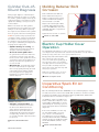
Cylinder Out-ofRound Diagnosis
Molding Retainer Bolt
Corrosion
During engine diagnosis of 2014 and prior
GM cars and trucks for engine oil consumption, misfire, cylinder leakage or blow-by, an
engine block may be inspected for possible
cylinder bore damage, scoring or an out-of
round condition.
Some 2014 Silverado 1500 and
Sierra 1500 trucks built prior to
August 13, 2013 may have a front
side door window belt molding retainer bolt that is corroded.
GM has not had an issue with cylinders
being machined out-of-round for any engine
family in recent history. When inspecting
the engine block to determine if the cylinder
bores are good, look for the following items.
TIP: The peak-to-valley specification for
crosshatch is 0.65 – 2.8 microns. Any deviation and the crosshatch will be gone. Even
if a cylinder is suspected of being oversize,
it can only be confirmed by checking with an
air gauge at the engine plant.
•Cylinder damage or scoring – the
cylinder walls will contain grooves deep
enough to catch with a fingernail.
•An out-of-round cylinder bore –
the cylinder will contain areas where the
crosshatch is missing or worn from different sections of the cylinder bore. If the
crosshatch is all the way around the bore
from top to bottom, the cylinder bore is
not out-of-round.
•Dirt intrusion – If the filtering system
has been compromised, the engine will
wear out very quickly. Grit may be found
in the intake runners and the cylinder
bores may appear to be lightly sand
blasted. The crosshatch will be faint
without sharpness.
Replace the bolt with part number
11515397. Apply Red Thread Adhesive (P/N 89021297, U.S.; P/N
10953488, Canada) or equivalent to
the bolt threads.
Tighten the bolt to 27 lb.-in. (3 N-m).
Thanks to James Will
Corroded molding retainer bolt
Electric Cup Holder Cover
Operation
The 2014 CTS sedan features a center console electric cup holder cover. The
cover may become inoperative if the customer has pushed the cover up and over
the full open stop, where the cover is open and will not close.
Gently pull up and rearward at the same
time on the front of the cup holder
cover. Use a trim stick to gently pry up
the rear portion of the cover to lift the
rear edge up and over the full open stop.
This procedure should reposition the
door to the correct side of the stop and
allow proper operation.
Advise the customer not to use excessive force while operating the cover.
Thanks to Stephen Jacob
Electric cup holder cover
Inoperative Spark EV Air
Conditioning
On some 2014 Spark EV models (RPO EN0), the air conditioning may be inoperative and/or the Service Vehicle Soon (SVS) MIL (resembles a car with an exclamation mark in the middle) may be illuminated. A history DTC P0071 (Ambient Air
Temperature Sensor Performance) may be set.
Out-of-round cylinder
•Catalytic converter failure – If a
converter fails and the brick is broken,
the dust can be drawn back into the
engine. A block showing this type of
failure will have bores that look to be
sand blasted. Back cylinders will go first
if caught early; otherwise, there will be
no crosshatch and the engine will need to
be replaced.
Thanks to Richard Renshaw
Use GDS2 to capture any DTC Freeze
Frame or Failure Records prior to clearing the DTCs. If DTC P0071 is current
(failed during the current key cycle), follow the appropriate Service Information
diagnostics.
If the vehicle build date is before July
15, 2013 and the DTC is set in history, or there is an intermittent no
air conditioning concern, the Hybrid
Powertrain Control Module 2 (HPCM2)
software needs to be updated. Program
the K114B (HPCM2) software using
TIS2Web.
Thanks to Brian Ciaverella
December 2013
7
Service Vehicle Soon MIL
Revised Operation of Hazard Switch
A BCM calibration has changed the operation of the hazard switch on 2014 CTS sedan
models produced after October 11, 2013, or any vehicle that has had the BCM programmed during service. After the calibration update, the hazard switch must be pressed
and held for one second before the hazard flashers will operate.
Advise customers that the hazard flashers may not activate during the first press of the
switch if the switch is not held for one second.
Thanks to Stephen Jacob
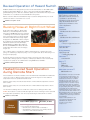
Buzzing Noise at Right Front Wheel
Some 2012-2013 LaCrosse, Regal; 2013
Malibu Eco; and 2014 Impala Eco models
with eAssist (RPO HP6) may have a buzzing
or humming noise heard in the right front at
times, both when turning or driving straight.
The Service Brake Assist message may be
displayed or the ABS MIL or Service Engine
Soon MIL may be illuminated. DTCs C027B
(Brake Booster Electric Vacuum Pump),
C0040 (Right Front Wheel Speed Sensor
Circuit) and P0CBE (Drive Motor Coolant
Temperature Sensor Circuit Low Voltage)
may be set.
Editor:
Lisa G. Scott
GM Customer Care and Aftersales
Technical Editor:
Underhood wire harness
contacting pulley.
Thanks to Christopher Crumb
Production Manager:
Desktop Publishing:
5by5 Design LLC
/ [email protected]
FAX number:
3
1-248-729-4704
Write to:
*
TechLink
PO Box 500
Troy, MI 48007-0500
Heated/Cooled Seat Operation
during Remote Start
The heated and cooled seats available on the 2014 Silverado 1500 and Sierra 1500 trucks
can be set to turn on during a remote start. The seats will only turn on if the ambient
temperature meets the predetermined threshold.
During a remote start, the heated seats will turn on when ambient temperature is below
50° F (10° C).
During a remote start, the cooled seats will turn on when ambient temperature is above
80° F (27° C).
Use the Vehicle Settings menu to enable the seats to turn on during a remote start.
TIP: The heated or cooled seat indicator lights do not turn on during a remote start and
the temperature performance of an unoccupied seat may be reduced. This is normal.
Thanks to James Will
10213.12D Emerging Issues
Mark Spencer
/ [email protected]
Marie Meredith
Repair the wiring as needed or replace the harness. Properly route and secure the
harness. Once wiring repairs are complete, confirm proper brake booster vacuum pump
operation. The pump can be commanded on using GDS2. Clear all DTCs.
Publisher:
John Meade
GM Customer Care and Aftersales
This condition may be caused by the underhood wiring harness contacting the crank
pulley, air conditioning compressor pulley or accessory drive belt due to misrouting or not
being secured properly.
Service
Know-How
GM TechLink is published for all
GM retail technicians and service
consultants to provide timely
information to help increase know
ledge about GM products and
improve the performance of the
service department.
December, 12 2013
To view Emerging Issues seminars:
• Log in to www.centerlearning.com
– Select Resources, and then Video on Demand; or
– Select Catalog to search for the course number, and then
select View > Take or Continue Course
8
GM TechLink on the Web:
GM GlobalConnect
:
General Motors service tips are intended
for use by professional technicians, not
a “do-it-yourselfer.” They are written to
inform those technicians of conditions
that may occur on some vehicles, or to
provideinformation that could assist in
the proper service of a vehicle. Properly
trained technicians have the equipment,
tools, safety instructions and know-how to
do a job properly and safely. If a condition
is described, do not assume that the
information applies to your vehicle or that
your vehicle will have that condition. See a
General Motors dealer servicing your brand
of General Motors vehicle for information
on whether your vehicle may benefit from
the information.
Inclusion in this publication is not
necessarily an endorsement of the
individual or the company.
Copyright© 2013 General Motors
All rights reserved.
December 2013
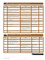
Car Issues – Fix It Right the First Time
Model
Year(s)
Vehicle Line(s)/Condition
Do This
Don’t Do This
Reference
Information/
Bulletin
2013
SRX, XTS, ATS – Incorrect Gulf of Mexico map
location
A S/W update has been released to address
this condition. A USB drive (Blue) was sent
to dealers.
Replace the HMI or any other
components for this issue.
PI1062
2013-2014
ATS, XTS, SRX, Impala, CTS – Diagnostic tips
for adaptive cruise control inoperative or adaptive
cruise control temporarily unavailable message
displayed on DIC
Install accessory grille on non-adaptive cruise
control vehicles only.
Install accessory grilles on
vehicles w/adaptive cruise
control.
PI1036B
2012-2013
LaCrosse, Regal, Malibu – Product Safety - Loss of
battery charge – replace generator control module
Replace the Generator Control Module.
Replace the Generator
Control & Battery Module.
13142
2012-2014
Sonic – Shifter handle knob cracked and/or will not
operate while shifting out of Park
Replace shifter handle.
Replace shifter assembly.
PI1086
2014
ATS – Engineering Information - Increased steering
effort, service power steering message displayed
on DIC, DTCs C047A, C056D, C056E, C0544 or
C0475 set
Contact Engineering as requested.
Replace the steering gear.
PIE0271
2013
ATS – Software Update (over the air) for adaptive
forward lighting system
Reprogram the Headlamp Control Module.
Replace the Headlamp
Control Module.
PI1078
2013-2014
ATS – Intermittent service power steering message
on vehicle start-up
Check ground G104 and underhood fuse
connections.
Replace the steering gear.
PI1097
2014
Malibu – Transmission fluid leak at auxiliary pump
seal
Contact the Warranty Parts Center and
request WPC part number 735, Aux pump
seal.
Replace the transmission
assembly or aux pump.
PI1071
2011-2014
Encore, Trax, Volt, Sonic, Cruze – Information on
water pump replacement
Confirm there is an existing leak before
deciding to replace the water pump.
Replace the water pump for
slight staining around the
coolant reservoir cup plug.
PI1041A
2006-2014
Corvette – Front tire chatter/noise vs. rear
differential chatter
While in a slow full turn (steering wheel
turned all the way in one direction), slowly
accelerate until the noise is heard. Unwind
the steering wheel 90 degrees and maintain
the same speed. If the noise goes away or is
significantly diminished, this is considered tire
hop and it cannot be corrected.
Drain or refill the differential.
It is not a differential fluid
concern.
09-04-20-001D
2011-2013
Cruze – Odor from HVAC system with temperature
control set on high heat and engine at operating
temperature
Order part from CCA warehouse.
Place order through
Warranty Parts Center.
PI0935B
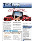
Truck Issues – Fix It Right the First Time
Model
Year(s)
Vehicle Line(s)/Condition
Do This
Don’t Do This
Reference
Information/
Bulletin
2014
Sierra, Silverado – Information on accessory bed
liner installation for pre-drilled bed liners and for
vehicles equipped with upper tie-downs
Notch plugs prior to install.
Make notches too big or
multiple notches.
PI0983A
2014
Impala Limited, CTS-V Sport Wagon, CTS-V
Coupe, CTS-V, CTS, Traverse, Enclave, Acadia,
Escalade ESV, Escalade, Yukon XL, Yukon,
Suburban, Tahoe – Malfunction Indicator Lamp
(MIL) on, DTC P069E set
Replace the fuel pump flow control module
if there is a DTC P069E set within this build
range.
Replace other system
components.
PI1082
2011-2014
Terrain, Equinox – Wet carpet/floor at driver and/
or passenger foot well areas
If water or water spotting has been diagnosed
in the driver and passenger front foot well
areas, water test for leaks in the roof ditch
molding along the roof panel.
Repair/replace sunroof
module or drains unless
suspect. Or repair/replace
windshield seal unless
suspect.
PI1090
2014
Silverado, Sierra – Warm air exhausting from driver
and/or passenger front seat back into 2nd-row
seating area causing occupant discomfort
Remove blower duct if a customer finds the
warm air objectionable.
Replace seat components.
PI1091
2014
Traverse, Acadia, Enclave – Service All Wheel
Drive message displayed on DIC, DTC U0136 set
Reprogram the Rear Differential Clutch Control
Module.
Replace the Rear Differential
Clutch Control Module.
PI1074A
2006-2013
Savana, Express – Front shock mount bracket crack
Install spring seat reinforcement if cracked.
Replace vehicle frame.
PI1080
Customer Care and Aftersales
December 2013
9