1
OWNER'S MANUAL
Warning:
“This equipment has been tested and found to comply with the limits for a Class B digital
device, pursuant to Part 15 of the FCC Rules. These limits are designed to provide
reasonable protection against harmful interference in a residential installation. This
equipment generates, uses, and can radiate radio frequency energy and, if not installed and
used in strict accordance with the instructions, may cause harmful interference to radio
communications. However there is no guarantee that interference will not occur in a
particular installation. If this equipment does cause harmful interference to radio or
television reception, which can be determined by turning the equipment off and on, the
user is encouraged to try to correct the interference by one or more of the following
measures:
—
—
—
—
Reorient the receiving antenna
Increase the separation between the equipment and receiver.
Connect the equipment into an outlet on a circuit different from that to which the
receiver is connected.
Consult the dealer or an experienced radio/TV technician for help.
“It is necessary to use shielded interconnect cables to insure compliance with FCC Class B
limits for radio frequency emissions."
Caution: Changes or modifications not expressly approved by the party responsible for
compliance could void the user’s authority to operate the equipment.
This manual and the program samples described in it are copyrighted by SEIKO
Precision Inc. with all rights reserved. No part of this publication may be
reproduced, stored in a retrieval system, or transmitted, in any form or by any
means, mechanical, photocopying, recording or otherwise, without the prior written
permission of SEIKO Precision Inc.
* Epson is a registered trademark of S.Epson Corporation.
* IBM is a registered trademark of International Business Machines Corporation.
* Windows is a registered trademark of Microsoft Corporation.
Copyright © 1998 by SEIKO Precision Inc.
Chiba, Japan
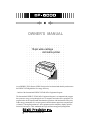
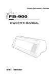
OWNER'S MANUAL
18-pin wide-carriage
dot matrix printer
As an ENERGY STAR Partner, SEIKO Precision Inc. has determined that this product meets
the ENERGY STAR guidelines for energy efficiency.
- Outline of the International ENERGY STAR Office Equipment Program The International ENERGY STAR Office Equipment Program is an innternational program
that promotes energy saving through the use of computers and other office equipment. The
program backs the development and dissemination of products with functions that effecyively
reduce energy consumption. It is an open system in which businness proprietors can participare
voluntarily. The targeted products are office equipment such as computers, displays, printers,
facsimiler, and copiers. Their standarads and logos uniform among participating nations.
C
1998 SEIKO Precision Inc.
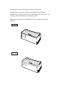
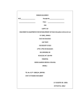
This manual is for the following two models of the printer.
Although these two models, Model A and Model B, look different,
the difference is only the appearance of the casing areas at the front. The
functions of these models are very much the same.
Refer to the manual of the model Model A, for the manual of the model
Model B.
Model A
Model B
Contents
Unpacking the printer
...........
1
Q u i c k s t a rt u p . . . . . . . . . . . . . . . . . . . . . . . . .
2
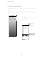
5 . Extended setup options
1 . I n t ro d u c t i o n
...................................
3
About extended setup options . . . . . . . . . 3 1
Options and expendables . . . . . . . . . . . . . . .
4
Basic setup option summury . . . . . . . . . . . . 3 2
Printer description
6
Extended setup option summury. . . . . . . . . 3 3
Features
......................
Setting top of form position . . . . . . . . . . 3 5
Paper width . . . . . . . . . . . . . . . . . . . . . . . . . . . . . . . 3 5
2 . Setting up
Installing the paper rack . . . . . . . . . . . . . . . 1 0
Setting maximum print line length . . . 3 5
Installing the sound seal cover . . . . . . . . 1 0
Line feed spacing . . . . . . . . . . . . . . . . . . . . . . . . 3 6
Installing the ribbon cassette
. . . . . . . . 11
Override bottom marg i n . . . . . . . . . . . . . . . . 3 6
.............. 12
Autoscroll mode . . . . . . . . . . . . . . . . . . . . . . . . . . 3 7
Connecting the power cord . . . . . . . . . . . . . 1 2
Label mode . . . . . . . . . . . . . . . . . . . . . . . . . . . . . . . . 3 7
Loading the paper . . . . . . . . . . . . . . . . . . . . . . . . 1 3
Set default page length
Adjusting the print head position. . . . . . . 1 5
Disable paper out detection . . . . . . . . . . . . 3 8
Connecting the computer
Disable paper out buzzer
3 . C o n t ro l p a n e l a n d o p e r a t i o n s
................. 38
............... 38
Skip over perforation . . . . . . . . . . . . . . . . . . . 3 9
Control panel and indicators . . . . . . . . . . . 1 6
Line Feed Speed . . . . . . . . . . . . . . . . . . . . . . . . . . . . 3 9
Paper parking . . . . . . . . . . . . . . . . . . . . . . . . . . . . . 2 0
Set CSF (cut sheet feeder) type . . . . . . . . . 3 9
Printing test pattern . . . . . . . . . . . . . . . . . . . . . 2 1
Emulation . . . . . . . . . . . . . . . . . . . . . . . . . . . . . . . . . 4 0
Tearing off a form . . . . . . . . . . . . . . . . . . . . . . . . 2 2
National font style . . . . . . . . . . . . . . . . . . . . . . 4 0
Power On Operation summary . . . . . . . . . . . 2 3
Code page . . . . . . . . . . . . . . . . . . . . . . . . . . . . . . . . . . 4 1
EURO symbol(ISO 8859-1). . . . . . . . . . . . . . . . .4 1
4 . Basic setup options
About basic setup options
Slashed zero................................. 4 2
............. 24
Character table . . . . . . . . . . . . . . . . . . . . . . . . . . . 4 2
Selecting font style . . . . . . . . . . . . . . . . . . . . . 2 6
Carriage return (CR) . . . . . . . . . . . . . . . . . . . . . 4 2
Selecting character spacing . . . . . . . . . . . . 2 7
Line feed (LF)
Selecting page length for fanfold paper 2 8
Set vertical tabs (VT) in BP-A/I mode . 4 3
Selecting single sheet paper size. . . . . . . . . 2 9
IBM 20 cpi character spacing . . . . . . . . . . 4 3
Printing multipart paper . . . . . . . . . . . . . . . . 3 0
IBM download character table . . . . . . . . . 4 3
Loading user setup options
Set italic character style . . . . . . . . . . . . . . . . 4 4
............ 30
Printing list of option settings . . . . . . . 3 0
............................ 43
Set bold character style
................ 44
Enable bar code command . . . . . . . . . . . . . . . 4 5
Set bar code type . . . . . . . . . . . . . . . . . . . . . . . . . 4 5
Bar code size
............................. 46
Interface type . . . . . . . . . . . . . . . . . . . . . . . . . . . . . 4 7
Parity bits
................................ 47
Data length . . . . . . . . . . . . . . . . . . . . . . . . . . . . . . . 4 7
Stop bit
B . Control code summary
................................... 47
IBM mode . . . . . . . . . . . . . . . . . . . . . . . . . . . . . 6 9
Communication protocol . . . . . . . . . . . . . . . 4 8
FX mode . . . . . . . . . . . . . . . . . . . . . . . . . . . . . . . 7 4
Communication speed . . . . . . . . . . . . . . . . . . . 4 8
BP-A/I mode . . . . . . . . . . . . . . . . . . . . . . . . . . . 8 0
Serial error check . . . . . . . . . . . . . . . . . . . . . . . . 4 8
Setup options control codes . . . . . . . 8 4
CST signal setting . . . . . . . . . . . . . . . . . . . . . . . . 4 9
Bar code control codes . . . . . . . . . . . . . . . 8 8
DSR signal setting . . . . . . . . . . . . . . . . . . . . . . . . 4 9
CD signal setting . . . . . . . . . . . . . . . . . . . . . . . . . 4 9
C . Character sets
............ 50
FX Italic character set . . . . . . . . . . . . . . . 9 1
ERROR/PE signal setting . . . . . . . . . . . . . . . . 5 0
FX Italic character set, extended . . . . 9 1
Print direction . . . . . . . . . . . . . . . . . . . . . . . . . . . . 5 0
FX Graphic character set . . . . . . . . . . . . 9 2
Invert LCD Display. . . . . . . . . . . . . . . . . . . . . . . . . 5 1
FX Graphic character set, extended
Energy Star . . . . . . . . . . . . . . . . . . . . . . . . . . . . . . . . . 5 1
IBM character set 1 . . . . . . . . . . . . . . . . . . 9 3
Saving user setup options . . . . . . . . . . . . . . 5 1
IBM character set 2 . . . . . . . . . . . . . . . . . . 9 3
Restore factory default setups . . . . . . . . . 5 2
IBM all character set . . . . . . . . . . . . . . . . 9 4
Software controlled setup . . . . . . . . . . . . . . 5 3
International character set . . . . . . . . . 9 4
Reset Lock. . . . . . . . . . . . . . . . . . . . . . . . . . . . . . . . . . . 5 3
BP-A character set . . . . . . . . . . . . . . . . . . . 9 5
Communication buffer size
6 . S e t t i n g t h e a p p l i c a t i o n s o f t w a re
About printer driver . . . . . . . . . . . . . . . . . . . . . 5 4
Printer driver selection . . . . . . . . . . . . . . . . . 5 4
7 . Tro u b l e s h o o t i n g
Error messages . . . . . . . . . . . . . . . . . . . . . . . . . . . . 5 5
Problem guide . . . . . . . . . . . . . . . . . . . . . . . . . . . . . 5 6
Input hexadecimal dump mode . . . . . . . . . 5 7
8 . Maintenance
Cleaning . . . . . . . . . . . . . . . . . . . . . . . . . . . . . . . . . . 5 8
Lubrication . . . . . . . . . . . . . . . . . . . . . . . . . . . . . . . 5 9
Printer cover removal . . . . . . . . . . . . . . . . . . . 5 9
Vertical alignment mode . . . . . . . . . . . . . . . . 6 1
Appendices
A . Specifications
Printing specifications . . . . . . . . . . . . . 6 3
Parallel interface specifications . . 6 6
Serial interface specifications . . . . 6 7
Other specifications . . . . . . . . . . . . . . . . 6 8
92
BP-I character set 1
................. 95
BP-I character set 2
................. 96
Code Pages . . . . . . . . . . . . . . . . . . . . . . . . . . . . . 9 7
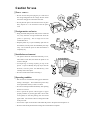
Caution for use
❏ Power sourc e
• Be sure to insert the power plug only in a wall unit of
the voltage designated in the voltage selector switch
and on the rating plate on the back of the unit.
• Do not place the power cord near heat sources or place
heavy objects on it. Do not bend or twist the power
cord.
❏ Foreign matter and water
• Keep your hands and personal items, such as scarfs and
ties, away from the carriage mechanism while the
printer is operating. The carriage moves with
considerable force.
• Keep the printer dry. If you accidentally spill water on
the machine, turn the power off immediately and wipe
it dry. Do not turn the power on until the machine is
completely dry.
❏ Installation environment
• The printer should be used where humidity is low,
where there is little dust, and where the printer is not
in direct sunlight.
• Avoid placing or leaning anything on top of the
printer. If you accidentally drop any object into the
machine, turn the power off immediately, t h e n
carefully remove the object.
• Do not twist the ribbon while installing it.
❏ Operating condition
• Wait at least two seconds after turning power off before
turning it back again. The initialization process may
not be performed correctly if this is not done.
• Do not touch the print head immediately after printing
because it is too hot.
• Never operate the printer without paper or paper
properly installed. If you use paper that is not as wide
as the platen, be sure that printing does not exceed
paper width. Use software control to change the width
of the print line.
• Never insert or pull out an interface cable while the power to the printer and computer is on.
• Be sure to turn off the printer before turning off a connected host computer.
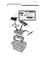
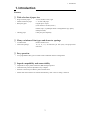
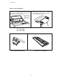
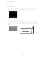
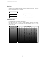
Unpacking the printer
Unpacking the printer
M.LF
M.RLF
TOF SET
PARK
SETUP
BIN
EXIT
ENTER
D
LF
C
RLF
L
ON LINE TEAR OFF
P.OUT
ON LINE
POWER
FF
RESET
BUSINESS PRINTER
Reverse Control Panel
CD-ROM
Handbook
Driver-CD with Owner's
Manual, printer driver software
Handbook
Operation Guide Sheet
Paper Rack
Sound Seal Cover
Ribbon Cassette
Power Cord
Printer
1
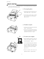
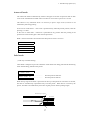
Quick startup
Quick startup
To make your first print, follow the procedure below . For more detailed instructions on setting your
printer, please refer to the page indicated.
❏ To set up the printer
1. Install the paper rack, the sound seal cover,
and the ribbon cassette — Pages 10 and 11.
2. Load the single cut sheet paper or fanfold
paper. Press the FF key to load the paper —
Pages 13 and 14.
❏ To make a test print
Self
Test
Self
Test
1. Set the paper size to the printer in the setup
options — Pages 28 and 29.
2. Press the LF key and hold while initializing
the printer by the RESET key. Hold the LF
key until the self test starts — Page 21.
?
?
❏ To connect your computer
1. With all equipment turned off, connect the
?
?
?
?
printer to your computer. Interface cable is
purchased separately — Page 12.
2. Use the extended setup options (emulation
type and communication enhancement
section) to match the specification needs
between the printer and your computer —
Pages 47 to 50.
3. Select the printer driver from your
application software — Pages 40 and 54.
2
1. Introduction
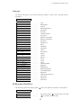
1. Introduction
Features
❏ Wide selection of paper size
• Single cut sheet papers
• Fanfold continuous paper
• Multi-part paper
A3, A4, B4, B5, Letter, Legal
5 - 16 inch wide paper
Original plus 6 copies
(total clearance: 0.41mm (0.016”)
Double, triple, or quadruple strikes to strengthen the copy quality
(Multipart mode)
• Labeling paper
Label peel-proof capability
❏ Many variations of font types and character spacings
• 2 resident fonts
Roman and Sans serif
• 6 character spacings
10, 12, 15, 17.1, 20 characters per inch (CPI), and proportional
characters
❏ Easy operation
• User programmable files give an instant switch to different interface configuration.
❏ Superb compatibility and connectability
• Compatible to major printer emulations, IBM and Epson printers.
• Communication protocols adjustable to any computer.
• Interface connections provided for parallel and RS-232C.
• Parallel and serial interface are switched automatically, when "AUTO" setting is selected.
3
1. Introduction
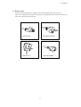
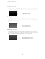
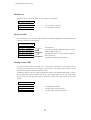
Options and expendables
We recommend the use of the Pull Tractor, especially,
when using the extra-thick papers or performing
continuous operation. This is the preferred path since it
is the most efficient paper feed path.
The Cut Sheet Feeder provides fast and automatic feeding
of Cut Sheet on the BP-6000. It greatly enhances the speed
and efficiency of document printing by feeding of up to 80
single sheets of paper without reloading.
Paper dimensions
Length: 14.5"~7.0"
Width : 15.0"~5.7"
Weight : 15~21 lbs.
Cut Sheet Feeder
Bin1 (#BP-78009)
Bin2 (#BP-78009E)
Pull Tractor (#BP-57008)
Matrix Print Head (#BP-57090-1)
Ribbon Cassette (#SBP-1051)
4
1. Introduction
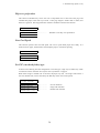
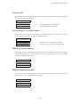
❏ Power cord
One of the following plug types is supplied. See "Connecting the power cord" on page 12.
Please see a rating plate on the back of your printer for appropriate input voltage and consult your
dealer for a specific type of power cord.
120V For USA
220-240V For Europe
240V For U.K.
240V For Australia
5
1. Introduction
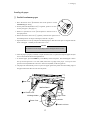
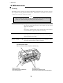
Printer description
Ribbon Cassette
Paper Guide
Platen
Paper Bail
Paper Select Lever
(Friction Lever)
Head Adjustment Lever
Printhead
Power Switch
Sound Seal Cover
Printer Cover
Paper Cutter
Paper Rack
Top Rear Cover
Operator Panel
Tractor Lock Lever
Rear Cover
Tractor Cover
6
1. Introduction
❏ Operation guide sheet
The operation guide sheet helps you to operate some of the basic options on the front control panel.
You can peel the sheet backing paper to stick anywhere on your printer.
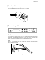
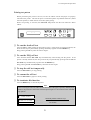
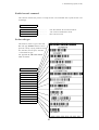
❏ Reverse control panel sheet
LF
M.LF
FF
M.RLF
RLF
PARK
TOF SET
RESET
D
ON LINE TEAR OFF
BIN
C
P.OUT
ON LINE
POWER
L
SETUP
ENTER
EXIT
Installation
The reverse control panel sheet allows you to easily read the function key labels from the back
of the printer. In situations where working from the back of the printer is convenient, simply
lay the reverse control panel sheet in position over the standard control panel.
Note:
If you set the invert display mode in the extended setup options, the display messages also
become upside down orientation.
E
N
I
L
N
O UT
O E
. N
P I R
L E
N W
O PO
T
E
A
R
O
F
F
F
F
R
L
F
L
F
M
.
R
L
M
F
.
T
Y
E
T
T
E
I
S
X
R
E
P
A
P
I
R
L
E
A
T
U
N
Q
F
E
L
U
P
P
A
R
L
C
D
K
R
E
S
E
T
7
1. Introduction
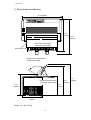
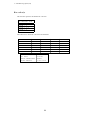
❏ Physical dimension(Model A)
24.4" (620mm)
17.5"
(445mm)
19.9"
(505mm)
∗Paper Rack in flat position
(Continuous paper setting)
Sound Seal Cover
∗Paper Rack in upright position
(Single sheet setting)
17.1"
15.4"
(435mm)
(390mm)
∗Paper Rack in flat position
(Continuous paper setting)
11.6"
(295mm)
10.2"
(260mm)
12.0 "
(305mm)
Weight: 44.1 lbs. (20 kg)
8
1. Introduction
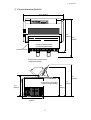
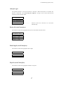
❏ Physical dimension(Model B)
24.4" (620mm)
18.5"
(470mm)
20.9"
(530mm)
∗Paper Rack in flat position
(Continuous paper setting)
Sound Seal Cover
∗Paper Rack in upright position
(Single sheet setting)
17.1"
(435mm)
∗Paper Rack in flat position
15.4"
(390mm)
(Continuous paper setting)
11.6"
(295mm)
10.2"
(260mm)
13.0"
(330mm)
9
2. Setting up
2. Setting up
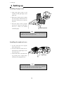
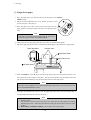
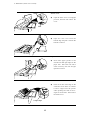
Installing the paper rack
1. Slide both paper guide to the
Pivots
extreme left and right edges of the
Groove
paper rack.
2
2. With the two small pivots on either
1
side of the paper rack downward, fit
the pivots in the groove on the rear
top cover.
3. Place the paper rack in upright
position for single cut sheet paper
and lay it down for fanfold
Rear Top Cover
continuous paper.
Note
The paper guides should be placed to the out edges during the
installation or removal of the paper rack.
Installing the sound seal cover
1. Lay the sound seal cover upside
down on the printer.
2. Fit one of the holes of the cover to
the stud of the L-angle hinge on one
side of the printer.
3. Fit the other hole to the other stud
L-angle Hinge
by pressing the L-angle hinge
inward then out through the hole.
Note
Make sure that both studs are out through the hole completely,
otherwise, the sound seal cover will be stuck in place.
10
2. Setting up
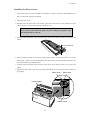
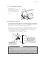
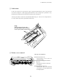
Installing the ribbon cassette
Turn OFF the printer's power and before the installation. However, the power should remain ON if
data is in the printer waiting to be printed.
1. Open the printer cover.
2. Manually move the print head to the extreme right side of the printer for easy installation of the
ribbon. Do not try to move the print head if the power is on.
CAUTION
Do not touch the print head if the printer has been running for a long time. Wait
until the print head is cooled off.
3. Turn the ribbon feed knob in the direction of the arrow on the knob to remove any slack in the
ribbon.
Re
mo
ve
Ribbon Feed Knob
an
ys
lac
k fr
om
rib
bo
n
4. Place the ribbon cassette on the left and right cassette holders, such that the ribbon rests on the
ribbon guide. Check to be sure that the ribbon drive shaft on the left cassette holder is inserted in the
hole on the bottom of the ribbon cassette.
5. Turn the ribbon feed knob in the direction of the arrow on the knob to remove any slack in the
ribbon.
6. Replace the front printer cover and set the head adjustment lever to the proper position for the best
print quality.
Ribbon Guide
Ribbon Mask
Cassette Holders
Cassette Holder
11
2. Setting up
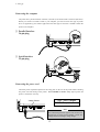
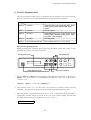
Connecting the computer
The printer has a parallel interface connector (Centronics) and serial interface connector (RS-232C).
Before you connect an interface cable to your computer, you need to know what type of printer
driver is supported by your software applications and what type of connector is needed to attach the
printer to the computer.
❏ Parallel Interface
36-pin plug
CAUTION
1
13
220-240V
120V
25
14
❏ Serial Interface
25-pin plug
CAUTION
13
220-240V
1
120V
T5A 250V
25
14
T2.5A 250V(For European)
Connecting the power cord
Check the power requirement printed on the rating plate on the rear of the printer before attaching
the power cord and turning on the printer. Both POWER and P.OUT lamps light up when the
printer is switched on correctly.
120V : USA, Canada
220-240V : Europe,Asia,Oceania
Voltage Selector
CAUTION
13
220-240V
120V
25
Note
For continued protection against risk of fire and
destruction of power PCB Assembly, switch the
voltage selector according to using voltage.
12
2. Setting up
Loading the paper
❏ Fanfold continuous paper
1. Move the friction lever qtoward the front of the printer to set the
FANFOLD paper setting.
2. Set the print head adjustment leverw. In general, position 1 is used
for one-part paper. (See page 15)
3. Remove or open the rear cover eof the printer to lock the cover in
the open position.
4. Release the tractor lock levers r (upward), and move the right tractor to
the marked position as shown in the figure, and lock it in place.
5. Open both tractor covers t and place the fanfold paper so that the tractor pins are aligned with the
holes in the paper. Carefully close both tractor covers.
Caution
Be careful not to catch your finger when closing the tractor covers.
6. After the paper is properly installed, re-adjust the left tractor to a position to keep the paper taut (but
not too taut) between the left and right tractors.
7. To load the paper, press the PARK key or the FF key on the front panel. The fanfold paper is fed to
the top-of-form position 17/72 inch (6mm) below the top edge of the paper. The top-of-form
position can be adjusted from 0/72 inch to 180/72 inch (64mm) in the setup options.
8. The paper bail automatically lowers to press the paper against the platen when the leading edge of
the paper feeds more than one inch onto the platen.
Rear Cover
Not Too Taut !!
Left Tractor Cover
Right Tractor
Left Margin Marker
Releasing direction
Tractor Cover
Tracter Lock Lever
13
2. Setting up
❏ Single sheets paper
1. Move the paper select lever qtoward the rear of the printer to the SINGLE
SHEET setting.
2. Set the print head adjustment lever w. In general, position 1 is used
for one-part paper. (See page 15)
3. Raise the paper rack to the vertical position and adjust the left
paper guide e to the proper position for the size of the paper being
used.
Note
If the paper is not loaded on the proper mark, the printer may
not detect the paper and will issue PAPER ERROR.
4. Place single sheet of paper against the paper rack and let it slide behind the platen.
5. Adjust the right paper guide so that it comfortably holds the paper in between the two paper guides.
Extension Arms
Paper Size Marker
Right Paper Guide
A3
Paper Select Lever
B4
Left Paper Guide
6. Press the PARK key or the FF key to load the single sheet paper to the top-of-form position 17/72
inch (6mm) below the top edge of the paper. The top-of-form position can be adjusted from 0/72
inch to 180/72 inch (64mm) by using the front panel controls in the setup option.
Note
If the paper is not completely fed in, slightly push the paper downward. If it is still not fed in, look
in the TROUBLESHOOTING section.
7. The paper bail automatically lowers to press the paper against the platen when the leading edge of
the paper feeds more than one inch onto the platen.
Notes
1. Extension Arms
The extension arms are used to keep large size (Legal, B4) cut sheet paper from falling
behind the paper rack. When using the extension arms, pull the arm until it clicks and locks
in place.
2. RLF, M.RLF, TEAR OFF, PARK keys are invalid in the cut sheet paper.
14
2. Setting up
❏ Vertical print position alignment
Current print line location
The current printing line (DDD...) is
Ribbon Guide
the third line down from the top of the
ribbon guide (line spacing is 1/6 line:
6 LPI).
0.5"
A
A A
A A B B B
B B C C
C C D D
D D
A
Adjusting the print head position
The head adjustment is used to obtain the best print quality possible for the specific paper
being used. The print head position can be adjusted to accommodate printing on single and
multipart forms. When using multipart forms, move the print head adjustment lever toward the
front of the printer to widen the gap between the print head and the platen.
In general, position 1 is used for one-part paper. Moving the head adjustment lever one notch
adjusts the print head gap an amount corresponding to the addition of one more paper part.
Re-adjustment of the lever may be required depending on the quality of the actual printout:
• If smears are shown on the paper, the gap is too narrow.
• If the printed image is too light to read, the gap is too wide.
Upper limit: Single sheet
First click: 2 layered paper
6th click: 5 layered papar
(This scale is only the
suggestive number of sheet
for non-carbon part-paper.)
Head Adjustment Lever:
Move toward the front of
the printer for thicker paper
Notes
1. The print head adjustment lever should be set before loading the paper to avoid any
paper jams.
2. If the printed image on the last copy of a multipart form is too light to read, set the
MULTIPART mode in the basic setup options (see page 30). This will increase the
striking intensity for multipart forms by double or more striking each character.
15
3. Control panel and operations
3. Control panel and operations
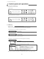
Control panel and indicators
Standard Panel
EXIT
ENTER
SETUP
BIN
M.LF
LF
FF
M.RLF
RLF
TEAR OFF
M.RLF
TOF SET
RLF
RESET
PARK
M.LF
D
LF
C
ON LINE TEAR OFF
P.OUT
ON LINE
POWER
FF
L
POWER
ON LINE
P.OUT
ON LINE
Alternate up-side down reverse panel
SETUP
BIN
EXIT
ENTER
D
PARK
C
TOF SET
L
RESET
❏ Indicators
• Display window
Liquid Crystal Display (LCD)
Displays status and errors during operation and menus in the setup options.
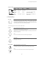
The followings are some examples of the display messages.
ONLINE
COVER OPEN
Status message
This indicates that the printer is in online and ready to print.
Warning message
This indicates that the printer cover is open. Close the cover to
resume the operation .
If the printer is in the offline mode, the following appears on the display.
OFFLINE DRAFT
Status message
This indicates a printing quality selected in the setup options.
This indicates that the printer is in offline.
QUALITY
NLQ
DRAFT
S.DRAFT
S.S.DRAFT
PRINT SAMPLE
Note: Refer to the Basic setup options or Extended setup options for their display messages.
16
3. Control panel and operations
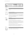
• Indicator lamps
POWER
ON LINE
P.OUT
Lamp
On
Off
Blinking
POWER
(green)
Power On
Power Off
ON LINE
(green)
Online
Offline
Cover open, or Head overheat
protection activating
P.OUT
(umber)
Out-of-paper
Paper-in
Home sensor error, RAM error,
or paper error.
—
ON LINE
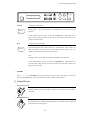
❏ Function Keys
• ON LINE
ON LINE
Pressing this key places the printer offline so that the printer can perform
some functions independent from host system. In the offline mode, data is
not received. When the printer is offline, pressing the key places the printer
online and ready to receive data from the host system.
The following keys are active only in the offline mode
• LF/RLF
LF
(Line feed and reverse line feed)
When the LF/RLF key is pressed, paper is fed per the line spacing at the 6
line per inch forward or backward, respectively.
While this key is pressed and held, the paper is continuously fed forward or
backward, respectively.
Note:
The reverse line feed can not be used with single sheet paper.
RLF
• FF
(Form feed)
Pressing this key feeds the paper to the next top of form position. Single
sheet paper is fed to eject.
FF
• M.LF/M.RLF
M.LF
(Micro line feed/micro reverse line feed)
When the M.LF/M.RLF key is pressed, the paper is fed 1/432 inch forward
or backward, respectively. This key is used to set the paper position.
Note:
The micro reverse line feed can not be used with single sheet paper.
M.RLF
17
3. Control panel and operations
L
RESET
C
D
PARK
TOF SET
EXIT
ENTER
SETUP
BIN
M.LF
LF
FF
M.RLF
RLF
TEAR OFF
POWER
ON LINE
P.OUT
ON LINE
• TOF SET
Pressing this key sets the top of the form position at the current print head
position. However, this TOF position will not be restored after the power is
turned off.
TOF SET
• TEAR OFF
[Used only for fanfold paper]
Pressing this key advances the perforation of the form to the paper cutter so
that the paper can be torn off from the rest.
TEAR OFF
If this key is pressed after the paper is torn off, the paper is fed backwards
and the mode is returned to the offline mode. If the ON LINE key is
pressed instead of the TEAR OFF key, the paper is fed backwards and then
the mode is changed to the online mode.
• PARK
PARK
(Paper parking)
Pressing this key unloads the paper when the paper is loaded and loads the
paper when the paper is not loaded.
Fanfold continuous paper (Paper select lever in fanfold setting)
The paper is moved to the park position in the back of the printer by
pressing this key. When pressing this key with the paper in the park
position, the paper will be loaded to a print station which is between 0/72
and 180/72 inches from the leading edge of the paper, depending on the
loading position programmed in the setup option.
Single sheet paper loaded (Paper select lever in single sheet setting)
The paper in the print station will be ejected. When paper is in the paper
rack, the paper is moved to the print station by pressing this key.
• RESET
When the RESET key is pressed, the printer immediately enters the reset
state and prepares for the initialize operation, which is nearly the same
initialize operation as when the power is turned on.
RESET
18
3. Control panel and operations
L
RESET
• SETUP
EXIT
C
D
PARK
TOF SET
EXIT
ENTER
SETUP
BIN
M.LF
LF
FF
M.RLF
RLF
TEAR OFF
POWER
ON LINE
P.OUT
ON LINE
(Alternate to the EXIT)
When the SETUP key is pressed in the offline mode, the printer enters the
setup options. The setup options are explained later in the "Basic setup
options".
SETUP
In the setup options, this key is used as the EXIT key. When the key is
pressed in the setup options, the printer exits from the setup options and
enters the offline mode.
• BIN
ENTER
BIN
(Alternate to the ENTER)
This key is for selecting the active paper tray of the cut sheet feeder or the
paper feed method: BIN 1, BIN 2, BIN 1+2, or MANUAL. BIN 1, BIN 2, or
BIN 1+2 appears only when the cut sheet feeder (CSF) option is set. To
register, select and hold the key for one second.
Note
The paper select lever must be switched according to the selection.
In the setup options, this key is used as the ENTER key. When the key is
pressed in the setup options, the current selection in the setup options will
register to the printer.
• OTHERS
The ←, →, ↓, ↑ and ENTER keys become effective only in the setup options entered by
pressing the SETUP key. For more information refer to "Basic setup options"
❏ Control Levers
• Paper Select Lever
The paper select lever serves to switch between the fanfold continuous paper
setting and the single sheet paper setting (or CSF setting when CSF is
installed).
• Head adjustment Lever
This lever adjusts the gap between the print head and platen. The correct
gap adjustment for a different paper thickness is required to obtain optimum
print quality. See also page 15.
19
3. Control panel and operations
Paper parking
This function moves fanfold paper back to the push tractor position (park station) so that single
sheet paper can be used. Specially it is useful when switching from fanfold paper to single
sheet paper.
• Pressing the PARK key removes the fanfold paper from the print station so that single sheet
paper can be used.
• Switching of the paper select lever is required for the actual mechanical switching of the paper
path.
• Pressing the PARK key when the printer is in the paper-out state loads the selected paper
(fanfold or single sheet) to the top-of-form position.
The following chart explains the paper handling of the PARK key in the offline state:
Paper Select Lever
Continuous Paper
Single Sheets
P.OUT Indicator
ON
OFF
ON
OFF
Action
Autoload the paper (similar to the FF key)
Park the paper in the push tractor position
Autoload the paper (similar to the FF key)
Eject the paper (similar to the FF key)
Notes
1. Make sure that the setting of the paper select lever corresponds to the type of paper
being used.
2. The paper park function causes a PAPER ERROR in the following situations:
a) when the fanfold paper does not set in the park station (at the push tractors) after
moving more than 22 inches backward
b) when the paper (fanfold or single sheet) is not autoloaded to the print position after
feeding more than 8 inches (At this time, the printer tries to sense the paper in the
printer.)
c) when the single sheet paper is not ejected from the printer after advancing more
than 22 inches.
20
3. Control panel and operations
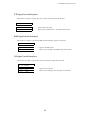
Printing test pattern
Before performing the printer's self test, be sure the ribbon cassette and paper are properly
installed in the printer. The self test prints a continuous pattern of printable characters (ASCII
character pattern) in either draft or near letter quality (NLQ).
While test printing is executed, the ON LINE lamp blinks and the LCD indicates “SELF
TEST”.
L
C
D
RESET
PARK
TOF SET
EXIT
ENTER
SETUP
BIN
M.LF
LF
FF
M.RLF
RLF
TEAR OFF
POWER
ON LINE
P.OUT
ON LINE
❏ To run the draft self test
Press the LF key while turning ON the printer's power. If the printer is already turned ON, the
draft self test may be performed by pressing the LF key together with the RESET key.
Keep pressing the LF key until the self test begins.
❏ To run the NLQ self test
Press both the LF and ON LINE keys simultaneously while turning ON the printer. If the
printer is already turned ON, the NLQ self test may be performed by pressing both the LF and
ON LINE keys simultaneously together with the RESET key.
Keep pressing the LF and ON LINE keys until the self test begins.
❏ To stop the self test temporarily
Press the ON LINE key to stop printing.
❏ To resume the self test
Press the ON LINE key again to restart printing.
❏ To terminate this function
Press the RESET key or turn off the power.
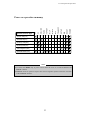
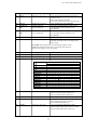
Note
Before initiating the self test, make sure that the width of the paper, especially fanfold paper
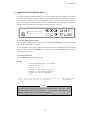
loaded in the printer fits within the maximum print length in a line selected in the extended
setup options.
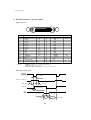
3. LINE WIDTH
WIDTH:13.6 INCH
WIDTH: 8 INCH
....................
....................
Maximum printable column at 10 cpi
136 columns
80 columns
21
3. Control panel and operations
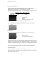
Tearing off a form
(Used only with fanfold paper)
This function is activated by the TEAR OFF key and feeds fanfold paper so that the
perforation is aligned with the paper cutter located at the top rear of the printer, thus enabling
simple paper tearing. During the tear off operation, the FF, PARK, M.LF, and M.RLF keys
are the only active keys and are used to correctly align the paper to the paper cutter.
After tearing off the form, pressing the TEAR OFF key a second time reverse feeds the paper
to the top of the next available form.
Paper Cutter
Note
Pressing the TEAR OFF key (or the ONLINE key) the second time may return the paper to
the original print position when the top edge of the form does not pass above the paper
cutter prior to the first TEAR OFF operation.
22
3. Control panel and operations
POWER
RESET
BIN
SETUP
TEAR OFF
RLF
M. RLF
M. LF
TOF SET
PARK
ON LINE
FF
Operation (reference page)
LF
Power-on operation summary
Self test, draft (P21)
Self test,NLQ (P21)
Hex dump, draft (P57)
Hex dump,NLQ (P57)
Vertical alignment (P61)
EEPROM initialize (P55)
Notes
1. Use either the RESET key or power switch when the circle is in both the RESET and
POWER columns.
2. EEPROM initialize operation requires the vertical alignment operation after the execution
of the EEPROM initialize.
23
4. Basic setup options
4. Basic setup options
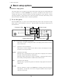
About basic setup options
The setup options serve to define various initial states of the printer that are executed when the
power is turned on or when the RESET key is pressed. In addition, this mode serves to
redefine the font type, character spacing, and other parameters for the printer's current
operating conditions. The parameters set in the setup options are stored in the memory of the
printer and used as the default values in initialize operations.
❏ To set this option
When the SETUP key is pressed in the offline mode, the printer enters the function setup
mode, where various functions can be set. The keys used in the function setup mode are
described below.
Exit setup to offline
L
C
Select menu
D
RESET
Select function
PARK
TOF SET
EXIT
ENTER
SETUP
BIN
Register selected setups
M.LF
LF
FF
M.RLF
RLF
TEAR OFF
POWER
ON LINE
P.OUT
ON LINE
Exit setup to online
← and → [Alternate to the PARK and TOF SET]
These keys are used to change the menu in the display, but cannot be used to
select a menu item.
↓ and ↑
[Alternate to the M.LF/M.RLF]
These keys are used to change an item within a menu in the display, but cannot
be used to set an item parameter.
ENTER
[Alternate to the BIN]
When this key is pressed while an item on the menu is displayed, the content of
the item is stored in the memory of the printer.
When the content of the item is saved, an asterisk (*) indicating that the item is
the currently selected parameter is added at the end of the item.
EXIT
[Alternate to the SETUP]
When this key is pressed, the printer exits from the setup options and enters the
offline mode.
ONLINE
This key's function is similar to the EXIT key in that the printer exits from the
setup options. At that time, if no errors or irregular conditions exist, the printer
enters the online mode.
24
4. Basic setup options
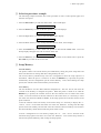
❏ Selection procedure example
The following example illustrates the correct procedure to select a letter-portrait paper size
from the front panel:
1. Press the ON LINE key to enter the offline state. The LCD displays:
OFFLINE DRAFT
2. Press the SETUP key to enter the SETUP options. The LCD displays:
1 FONT
3. Press the Right Arrow (→ ) key to select the menu and to display:
4 PAGE SINGLE
4. Press the Down Arrow (↓ ) key to step down the function items, and to display:
PG: LETTER PORT
5. Press the ENTER key to select letter-size portrait as the desired PAPER SIZE. The LCD
briefly displays the paper size with an asterisk at the end.
PG: LETTER PORT
*
6. Press the EXIT key to terminate the setup options and return to the offline state or press the
ON LINE key to return to the on line state.
❏ Setup Memory
Current memory
The printer contains one current memory for automatically storing the preset setup states and
three user memories for storing data that is designated by the user.
The current memory automatically stores the configuration when the setup options are
terminated. When the power is turned on or when the RESET key is pressed, the printer
automatically sets the configuration per the current memory. Thus, when entering the setup
options, the contents of the current memory can be altered.
User memory
The user memories can store three different configurations. The user can set and recall the
contents of the memory to configure the printer. When the power is turned on or when the
RESET key is pressed, the contents stored in the user memories are not used as the initial
values. To use the contents of the user memories as the initial values, it is necessary to select
one of the user memories, MEM1 to MEM3, in the setup options and evoke the contents as the
preset condition.
To use the contents of the user memory as the current setup, it is necessary to display the “6.
SELECT SETUP” on the menu and select one of the user memories. Exiting from the setup
options with a user memory selected will cause the contents of the user memory to be stored in
the current memory which then becomes the printer initial values.
To store a configuration in a user memory, display the “45. SAVE SETUP” selection in the
advanced setup options and select one of the user memories. The current setup content is
stored in the specified memory when exiting the setup options.
25
4. Basic setup options (1)
Selecting font style
Sets one of the font options. The font can be changed by a software command.
1 FONT
FONT: DRAFT
FONT: S.DRAFT
FONT: S.S.DRAFT
FONT: ROMAN
FONT:SANS SERIF
FONT
DRAFT
S.DRAFT
S.S.DRAFT
ROMAN
SANS SERIF
....................
Default font in a draft printing.
....................
Default font in NLQ print mode.
PRINT SAMPLE
26
4. Basic setup options (2)
Selecting character spacing
Sets one of the character spacings. When CODE is selected, the character spacing can be
changed by a software command.
When speed draft or super speed draft is set while a fixed spacing is designated, the character
spacing becomes 12 CPI or 15 CPI, respectively.
2 CHAR PITCH
PITCH: CODE
PITCH: 5 CPI
PITCH: 6 CPI
PITCH: 10CPI
PITCH: 12CPI
PITCH: 15CPI
PITCH: 17CPI
PITCH: 20CPI
PROPORTIONAL
CHARACTER PITCH
....................
Default character spacing is 10 cpi printing.
PRINT SAMPLE
5 CPI
6 CPI
10 CPI
12 CPI
15 CPI
17.1 CPI
20 CPI
Proportional
27
4. Basic setup options (3)
Selecting page length for fanfold paper
The page length selection varies`1` roughly from 2 inches to 22 inches according to the given
options.
When CODE is selected, the page length can be changed by a software command. When the
page length is other than CODE, it is a fixed length and a software command is ignored. The
page length is the same as the distance between two perforations.
3 PAGE FANFOLD
PAGE:
PAGE:
PAGE:
PAGE:
PAGE:
PAGE:
PAGE:
PAGE:
PAGE:
PAGE:
PAGE:
PAGE:
PAGE:
PAGE:
PAGE:
PAGE:
PAGE:
PAGE:
PAGE:
PAGE:
CODE
2
INCH
2.5 INCH
3
INCH
4
INCH
4.5 INCH
5
INCH
5.5 INCH
7
INCH
8
INCH
8.5 INCH
10 INCH
11 INCH
12 INCH
14 INCH
15 INCH
16 INCH
16.5 IN
17 INCH
22 INCH
....................
Default page length is 11 inches.
The default page length can be set to 12 inches at
"8.DEFAULT PG LNG" in the extended setup
options on page 38.
Print prohibited area
0/72"
or more
TOF (Top Margin)
Page Length
Lowest Bottom Margin
Skip
perforation area
28
(when skip perforation
mode is enabled)
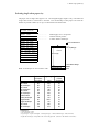
4. Basic setup options (4)
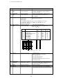
Selecting single sheet paper size
The paper size of single sheet paper is set. The designated page length is only valid when the
single sheet mode or CSF mode is selected. The relationships of the paper sizes with the
number of printed columns (at 10 cpi) are described in the table below.
4 PAGE SINGLE
PAGE: CODE
PAGE: B5 PORT
PAGE: B5 LAND
PAGE: A4 PORT
PAGE: A4 LAND
PAGE: B4 PORT
PAGE: B4 LAND
PG: LETTER PORT
PG: LETTER LAND
PAGE:LEGAL PORT
PAGE:LEGAL LAND
PAGE: A3 PORT
PAGE: A3 LAND
....................
....................
....................
Default page size is A4 portrait.
"PORT" denotes portrait.
"LAND" denotes landscape.
Print Prohibited area
0/72"
or more
TOF (Top Margin)
Page Length
Lowest Bottom Margin
Override BM area
Note: A3 landscape can not be used in CSF.
Paper Size
B5 Portrait
B5 Landscape
A4 Portrait
A4 Landscape
B4 Portrait
B4 Landscape
Letter Portrait
Letter Landscape
Legal Portrait
Legal Landscape
A3 Portrait
A3 Landscape
Number
of Columns
(char./line)
68
98
80
114
98
136
82
108
82
136
114
136
Page Length
(mm)
232
157
272
185
339
232
255
191
330.1
191
395
272
8mm
Number
of Lines
(line/page)
54
37
64
43
80
54
60
45
78
45
93
64
CONDITIONS
• Character Pitch: 10 CPI
• Line Feed Pitch: 6 LPI
• Page Length : = Paper form length - 6mm (top margin) - 17mm (bottom margin) - 2mm (tolerance)
• Right and Left Margin: correspond to the scale on the paper bail. (The unit is the number of characters).
29
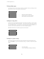
4. Basic setup options (5-7)
Printing multipart paper
The multipart mode increases the print intensity on multipart forms by striking the same
character twice or more in several passes of the print head.
5 MULTIPART
COPY:
COPY:
COPY:
COPY:
NORMAL
DARK1
DARK2
DARK3
....................
....................
....................
Print twice on the same character.
Print three times on the same character.
Print four times on the same character.
Loading user setup options
Loads one of three user designed setup options to the current active memory. This will replace
and erase setup contents in the current memory. The printer has three setup storage areas that
can store different setups. If you need to save the current setups before replacement, it is
necessary to select the “45 SAVE SETUP” item in the extended setup options.
Note: When this function is executed, the printer will be initialized.
6 SELECT SETUP
SETUP: MEM1
SETUP: MEM2
SETUP: MEM3
Printing list of option settings
This function prints the list of the current setups or/and all the setups of three memory areas.
Press the ENTER key to start the selected item listing. This does not affect the current
setting.
7 SETUP LISTING
LIST: CURRENT
LIST: ALL SETUP
....................
....................
Lists current setups.
Lists all setup listings including user memorys.
30
5. Extended setup options
5. Extended setup options
About extended setup options
The extended setup options contain various setup options which are used less frequently than
the main setup options.
For the overview of the extended setup options, refer to Extended setup options summary.
❏ To set this option
By pressing the Down Arrow ( ↓ ) key at the last menu item in the main setup options, the
printer enters the extended setup options, where various functions.
8 <SUB-MENU>
The keys and operation method in the extended setup options are the same as those in the basic
setup options. If a modification is made in the setup options, store it in one of user defined
memory areas described on page 51.
Exit setup to offline
L
RESET
C
Select menu
D
Select function
PARK
TOF SET
EXIT
ENTER
SETUP
BIN
Register selected setups
31
M.LF
LF
FF
M.RLF
RLF
TEAR OFF
Exit setup to online
POWER
ON LINE
P.OUT
ON LINE
DRAFT*
S.DRAFT
S.S.DRAFT
ROMAN
SANS SERIF
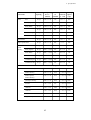
1.FONT
BASIC SETUP OPTIONS
CODE*
5 CPI
6 CPI
10 CPI
12 CPI
15 CPI
17 CPI
20 CPI
PROPORTIONAL
2.CHAR PITCH
CODE*
2
2.5
3
4
4.5
5
5.5
7
8
8.5
10
11
12
14
15
16
16.5
17
22
3.PAGE
FANFOLD
32
*
MEM 3
DARK 3
MEM 2
DARK 2
MEM 1
6.SELECT SETUP
DARK 1
NORMAL*
5.MULTIPART
The asterisk ( )indicates
the factory default setting.
CODE*
B5 PORT
B5 LAND
A4 PORT
A4 LAND
B4 PORT
B4 LAND
LETTER PORT
LETTER LAND
LEGAL PORT
LEGAL LAND
A3 PORT
A3 LAND
4.PAGE
SINGLE
(Press both the SETUP key to enter the setup options.)
Setup options summary
<8.SUB-MENU>
Select menu
Select function item
Register function item
Exit setup options
To extended setup options
ALL SETUP
CURRENT*
7.SETUP
LISTING
ENTER
EXIT
key:
key:
key:
key:
5. Extended setup options
33
YES
NO*
17.EURO SYMBOL
DETECTION
NO
YES*
9.P.OUT
DETECT
TOP: +n/72 IN
(0
n
180)
1.LOADING
ADJUST
9 IN*
9 IN
9 IN
9 IN*
NO-SRASH*
SLASHED
18.ZERO STYLE
SOUND*
NO-SOUND
10.P.OUT
BUZZER
SINGLE
WIDTH
WIDTH
FANFOLD
WIDTH
WIDTH
2.PAPER WIDTH
EXTENDED SETUP OPTIONS
ITALIC*
GRAPHIC
IBM SET1
IBM SET2
BP-A SET
19.CHARACTER
SET
SKIP
NO*
YES
11.1-INCH SKIP
PRINT LINE
13.6 INCHES*
8 INCHES
3.LINE WIDTH
*
5.OVERRIDE
PRINT
AUTO FEED*
CR+LF
CR ONLY
20.CR SETTING
NORMAL*
1/2
12.LF SPEED
CR+LF*
LF ONLY
21.LF SETTING
INSTALLED
NO*
1 BIN
2 BIN
13.CSF OPTION
OVERRIDE
CODE 6 LPI*
NO*
CODE 8 LPI
YES
8 LPI
9 LPI
The asterisk ( )indicates
the factory default setting.
4.LF PITCH
VT SETTING
WITH PRINT*
WITHOUT PRINT
YES*
NO
23.20CPI
SETTING
USA*
FRANCE
GERMANY
ENGLAND
DENMARK
SWEDEN
ITALY
SPAIN
JAPAN
NORWAY
DWNLD CHR.SET
COUNTRY*
MULTILINGUAL
24.DWNLD
CHR.SET
437*
850
857
858
860
861
863
865
BRASCII
ABICOMP
ISO-1
ISO-15
437 Greek
772
774
851
852
853
855
866
869
1250
1252
LTU-KBL
BULGARIA
IBM RUSS.
MAZOWIA
Code MJK
HUNGARIAN
USSR GOST
ISO-2
ISO-7
ISO-9
11 INCHES*
12 INCHES
8.DEFAULT
PG LENGTH
16.CODE PAGE
LABEL MODE
NO*
YES
7.LABEL MODE
15.NATIONAL
FONT
22.VT SETTING
DENMARK2
SPAIN 2
LATIN AMERICA
TURKEY
FX MODE*
IBM
BP-A
BP-I
14.EMULATION
AUTO SCROLL
NO*
TOF ONLY
ANY POS
6.AUTO SCROLL
5. Extended setup options
34
34.PROTOCOL
33.STOP BIT
STATUS SIGNAL
YES*
NO
41.ERROR
STATUS
PRE-DIRECTION*
UNI-DIRECTION
BI-DIRECTION
42.PRINT DIR
DTR*
XON/OFF1
XON/OFF2
ETX/ACK
BOLD MODE
CODE*
ALWAYS
ITALIC MODE
CODE*
ALWAYS
1 BIT*
2 BITS
26.BOLD
25.ITALIC
NO*
YES
43.INVERT DISP
BAUD RATE
9600 BPS*
4800
2400
1200
ENERGY STAR
YES*
NO
44.SLEEP MODE
PRINT *
IGNORED
36.SERIAL
ERROR
35.BAUD RT
EAN13
UPC-A
UPC-E
POSTNET
ELEMENT
BARCODE TYPE
INDSTRAL25
INTRLVD25
MATRIX
CODABAR
CODE11
CODE39*
CODE93
CODE128
EAN8
28.BC TYPE
BARCODE COMMAND
MODE 1*
MODE 2
IGNORED
27.BARCODE
MEM 1*
MEM 2
MEM 3
45.SAVE SETUP
YES
NO*
37.CTS ENABLE
1*
1.5
2
2.5
29.BC SIZE
46.FACTORY SET.
YES
NO*
37.DSR ENABLE
PARALLEL*
SERIAL
AUTO
30.INTERFACE
SOFTWARE SETUP
NO*
YES
47.SOFTWARE
SET.
YES
NO*
39.CD ENABLE
NONE*
ODD
EVEN
31.PARITY BIT
YES
NO*
48.RESET LOCK.
MAX.*
8KB
20KB
MIN.
128B
40.BUFFER SIZE
7 BITS
8 BITS*
32.DATA LENGTH
5. Extended setup options
5. Extended setup options (1-3)
Setting top of form position
The top margin can be set using this function, anywhere from a minimum of 0/72 inch (0mm)
to a maximum of 180/72 inches (64mm) by increments of 1/72 inch.
Press the Up or Down arrow keys to increase or decrease the top margin setting, respectively.
Press the ENTER key to select the desired
0/72~180/72 inches
0/72~180/72 inches
(Setup #1 Loading adjust) (Setup #1 Loading adjust)
setting.
1 LOADING ADJST
TOP:
TOP:
TOP:
Printable area
+ 0/72IN
+nnn/72IN
+180/72IN
Printable area
Printable area
Paper width
This function sets the paper width to be used in the printer. Depending on the paper width the
print head will shift to the one half of the print width selected in this function to properly hold
the paper in place, and to eliminate the possibillity of paper jams during loading.
2 PAPER WIDTH
SINGLE: >9 IN
SINGLE: <9 IN
FANFOLD: >9 IN
FANFOLD: <9 IN
....................
....................
Default setting for a cut sheet paper
Default setting for fanfold paper
Setting maximum print line length
This function sets the maximum printable length of a line of text. This function clears the data
in the print buffer.
Note: Be sure to set the line width to 8 inches when using the paper of its width less than 8
inches. Otherwise, printing directly on the platen may cause an irregular printout or paper
skew.
3 LINE WIDTH
WIDTH:13.6 INCH
WIDTH: 8 INCH
35
5. Extended setup options (4-5)
Line feed spacing
One of the line feed spacing options from either 6, 8, or 9 line per inch (LPI) is selected.
When CODE is selected, the line feed spacing can be changed by a software command. When
no line spacing is set in the software command, this value (6 or 8 LPI) is used as a linefeed.
4 LF PITCH
LF:
LF:
LF:
LF:
CODE 6 LPI
CODE 8 LPI
8 LPI
9 LPI
Override bottom margin
This function serves to reduce the bottom margin.
In the standard designation, the bottom margin is set to 17 mm from the bottom edge of the
paper. With this function, data can be printed up to 8mm from the bottom edge of the page.
However, in this case, print quality is not assured due to the restriction of the printer
mechanism.
5 OVERRIDE PRINT
BOTTOM MARGIN
OVERRIDE: NO
OVERRIDE: YES
OVERRIDE PRINT
OVERRIDE PRINT
OVERRIDE PRINT
8 mm
36
17 mm
5. Extended setup options (6-7)
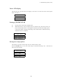
Autoscroll mode
The Autoscroll function automatically advances the paper to the tear off position when no data
exists in the communication buffer and no new data is received for a period of 1 second.
This feature is very beneficial when it is necessary to print a single invoice, and tear it off
immediately following printing.
In the case of "TOF ONLY" : Auto scroll is performed only when the present position, after the
printing, is at TOF.
In the case of "ANY POS" : Autoscroll is performed at any position after the printing if the
perforation is between the paper cutter and the print head.
i
Note: Autoscroll becomes invalid when the label protect mode is set active.
6 AUTO SCROLL
SCROLL:NO
SCROLL:TOF ONLY
SCROLL:ANY POS
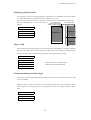
Label mode
(valid only in fanfold setting)
Label mode is designed to prevent continuous forms labels from being peeled from the backing
sheet and becoming jammed in the printer.
7 LABEL MODE
LABEL MODE: NO
LABEL MODE: YES
....................
....................
Set label protect mode off.
Set label protect mode on.
When the top edge of the label is positioned at the top of the platen for more than 10 seconds,
the label is automatically repositioned away from the platen. When data is received by the
printer, the labels are automatically fed to the original position before printing begins.
Backing Paper
Platen
Label
37
5. Extended setup options (8-10)
Set default page length
This function selects a default page length of either 11 or 12 inches at the time of printer
initialization. This selection is only valid when CODE is selected as the PAGE LENGTH
setting in the main setup options.
8 DFLT PG LENGTH
....................
....................
PAGE LNGTH:11
PAGE LNGTH:12
Page Length is 11 inches.
Page Length is 12 inches.
Disable paper out detection
When the paper empty detection function is disabled, the printer will not stop printing when a
paper empty error is detected and a software command with respect to the paper empty
detection function is not accepted.
9 P.OUT DETECT
DETECTION: YES
DETECTION: NO
....................
....................
Set paper empty detection on.
Set paper empty detection off.
Disable paper out buzzer
When SOUND is set and the paper empty condition is detected, the alarm sounds for one
second. When the NO-SOUND is set, the alarm does not sound. However, when P.OUT
DETECT is disabled, regardless of the alarm setting, the alarm does not sound.
10 P.OUT BUZZER
BUZZER:
SOUND
BUZZER:NO-SOUND
....................
....................
Set paper empty detection alarm on.
Set paper empty detection alarm off.
38
5. Extended setup options (11-13)
Skip over perforation
This function automatically leaves one inch of unprinted lines at the end of the page and
linefeeds the paper to the next top of form. If the page length is smaller than 5 inches, this
function is ignored. The skip perforation software command overrides this function.
11 1-INCH SKIP
1-INCH SKIP:NO
1-INCH SKIP:YES
....................
Defaults to non-skip over perforation.
Line Feed Speed
This function specifies the line feed speed. The 1/2 LF speed feeds paper more stably. It is
useful for thick paper, labeled sheets and multipart paper in continuous printing.
12 LF SPEED
LF SPEED:NORMAL
LF SPEED:1/2
Set CSF (cut sheed feeder) type
A function for defining the CSF configuration. The CSF type, single tray or double tray canbe
set when the CSF is installed. See "Options and expendables" on page 4.
When either single or double CSF is selected, the paper tray (bin 1 for single CSF and bin 1
and 2 for double CSF) can be selected by the BIN key on the front control panel.
13 CSF OPTION
INSTALLED:NO
INSTALLED:1 BIN
INSTALLED:2 BIN
....................
....................
....................
No CSF installed
Single CSF installed
Double CSF installed
39
5. Extended setup options (14-15)
Emulation
The desired emulation mode of the printer can be selected using this function. When this
function is executed, the printer is initialized.
14 EMULATION
EML:
EML:
EML:
EML:
FX MODE
IBM MODE
BP-A MODE
BP-I MODE
....................
....................
....................
....................
Epson FX-1050 compatible.
IBM Proprinter III XL compatible.
Seikosha BP-5460 Standard emulation.
Seikosha BP-5460 IBM emulation.
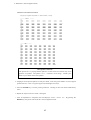
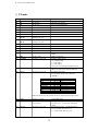
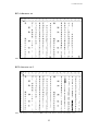
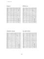
National font style
One of the following 14 national fonts can be selected.
When IBM Character Set 2 is selected, the Denmark, Denmark2, and Norway fonts take the
same characters as the U.S.A. font except that their codes 9Bh changes from "¢" to "ø", and
9Dh from "¥" to "Ø".
15 NATIONAL FONT
23 24
40
5B
U.S.A.
FRANCE
GERMANY
ENGLAND
DENMARK
SWEDEN
ITALY
SPAIN
JAPAN
NORWAY
DENMARK
SPAIN 2
LATN AMERICA
TURKEY
40
ASCII HEXADECIMAL
5C 5D 5E 60 7B
7C
7D
7E
5. Extended setup options (16-17)
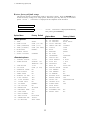
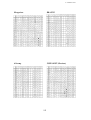
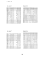
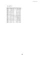
Code page
The default code page can be selected using this function. Refer to the code page table in
Appendix C.
16 CODE PAGE
C.P.:
C.P.:
C.P.:
C.P.:
C.P.:
C.P.:
C.P.:
C.P.:
C.P.:
C.P.:
C.P.:
C.P.:
C.P.:
C.P.:
C.P.:
C.P.:
C.P.:
C.P.:
C.P.:
C.P.:
C.P.:
C.P.:
C.P.:
C.P.:
C.P.:
C.P.:
C.P.:
C.P.:
C.P.:
C.P.:
C.P.:
C.P.:
C.P.:
437
850
857
858
860
861
863
865
BRASCII
ABICOMP
ISO-1
ISO-15
437 Gr
772
774
851
852
853
855
866
869
1250
1252
LTU-KBL
BULGA.
IBM RUSS.
MAZOWIA
MJK
HUNGARIAN
USSR GOST
ISO-2
ISO-7
ISO-9
....................
....................
....................
....................
....................
....................
....................
....................
....................
....................
....................
....................
....................
....................
....................
....................
....................
....................
....................
....................
....................
....................
....................
....................
....................
....................
....................
....................
....................
....................
....................
....................
....................
USA
Multilingual.
Turkish
Multilingual(Euro).
Portuguese
Icelandic
Canadian-French
Norwegian
Brazilian-Portuguese
Brazilian-Portuguese
ISO 8859-1
ISO 8859-15
Greek
Lithuanian
Lithuanian
Greek
East Europe
Turkey
Cyrillic
Russian
Greek
Latin 2
Latin 1
Lithuanian-KBL
Bulgarian
IBM Russian
MAZOWIA(Polish)
Code MJK(CSFR)
Hungarian
USSR GOST (Russian)
ISO 8859-2
ISO 8859-7
ISO 8859-9
EURO symbol (ISO 8859-1)
This function specifies the EURO symbol "
" at the code A4H in the character set ISO 8859-1.
17 EURO SYMB
EURO SYMBOL: YES ....................
EURO SYMBOL: NO ....................
The EURO symbol " "is printed at the code A4H.
" " is printed at the code A4H.
41
5. Extended setup options (18-20)
Slashed zero
The zero style is selected as either “0” (no-slash) or “Ø” (slashed).
18 ZERO STYLE
ZERO: NO-SLASH
ZERO: SLASHED
....................
....................
“0” (no-slash) is selected.
“Ø” (slashed) is selected.
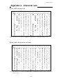
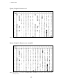
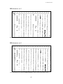
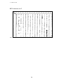
Character table
One of character sets is selected. The character set availability depends on the emulation mode
selected as shown in each selection.
19 CHARACTER SET
FX mode only
See italic and graphic tables on pages 91 and 92.
IBM and BP-I mode only
See IBM character set 1 and 2 tables on page 93.
BP-A mode only
See BP-A character table on page 95.
CH.SET: ITALIC
CH.SET: GRAPHIC
CH.SET:IBM SET1
CH.SET:IBM SET2
CH.SET:BP-A SET
Carriage return (CR)
A carriage return (ASCII code 0Dh or 13) causes data in the buffer to be printed and the
carriage to be moved to the next logical print position. The options shown below can be
selected when issuing a carriage return (CR code).
Autofeed is effective for the system using parallel interface and AUTO FEED signal to control
the carriage return with or without a line feed. The autofeed signal must be low to add a line
feed to every CR code when the printer is initialized. Refer to the specification of your host
system.
20 CR SETTING
CR: AUTOFEED
CR: CR+LF
CR: CR ONLY
....................
....................
....................
Autofeed signal enabled
Carriage return with a line feed
Carriage return without a line feed
42
5. Extended setup options (21-24)
Line feed (LF)
A function for executing the carriage return operation when receiving the line feed command
(LF code) is selected or deselected.
21 LF SETTING
LF : LF ONLY
LF : CR+LF
....................
....................
Line feed without a carriage return
Line feed with a carriage return
Set vertical tabs (VT) in BP-A/I mode
This function sets the vertical tab command code (0Bh) in BP-A or BP-I mode either to move
to next vertical tab with or without printing buffer content.
22 VT SETTING
VT: WITH PRINT
VT:WITHOUT PRNT
....................
....................
Move to a next vertical tab after printing.
Move to a next vertical tab without printing.
IBM 20 cpi character spacing
This function selects a condensed elite character (20 cpi) to be printed in either 20 cpi as in the
latest IBM emulation or 12 cpi (normal elite character spacing which is used in the IBM
emulation, Proprinter II or older).
23 20CPI SETTING
IBM 20CPI: YES
IBM 20CPI: NO
IBM download character table
This function selects between the country and multilingual character sets to be used in the
download area. See the character sets in appendix.
24 DWNLD CHR ST
COUNTRY SET
MULTILINGUAL
43
5. Extended setup options (25-26)
Set italic character style
This function simply selects all print output to be in italic character style.
25 ITALIC
ITALIC: CODE
ITALIC: ALWAYS
....................
....................
Defaults to the current set command code
Always printed in italic character style
Set bold character style
This function simply selects all print output to be in bold character style.
26 BOLD
BOLD : CODE
BOLD : ALWAYS
....................
....................
Defaults to the current set command code
Always printed in bold character style
44
5. Extended setup options (27-28)
Enable barcode command
This function enables the printer to accept the bar cord command and to print the bar cord
accordingly.
27 BARCODE
BC : MODE 1
BC : MODE 2
BC : IGNORED
....................
....................
....................
ESC SO and ESC SI can not be used for.
ALL control command are valide.
Bar Code is invalid.
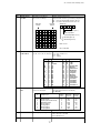
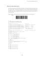
Set barcode type
This function selects a type of bar code.
Bar code type element enables a user to
print bar code by varying width of narrow
bar, wide bar, narrow space, wide bar,
or intercharacter gap.
See Appendix B, "Bar code control
code" for details.
28 BC TYPE
TYPE:
TYPE:
TYPE:
TYPE:
TYPE:
TYPE:
TYPE:
TYPE:
TYPE:
TYPE:
TYPE:
TYPE:
TYPE:
TYPE:
INDST25
INTRL25
MTRIX
CODABA
CODE11
CODE39
CODE93
C128
EAN-8
EAN-13
UPC-A
UPC-E
POSTNET
ELEMENT
45
5. Extended setup options (29)
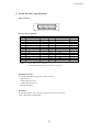
Bar code size
This function specifies the default bar code size.
29 BARCODE SIZE
SIZE
SIZE
SIZE
SIZE
:
:
:
:
1
1.5
2
2.5
The tables below show bar code sizes and attributes.
SIZE
NARROW BAR
WIDE BAR
NARROW SPACE
WIDE SPACE
INTER CHARA.GAP
BAR HEIGHT
1
2/120inch
6/120inch
2/120inch
6/120inch
2/120inch
8/12inch
HRI PRINT
HRI FONT
CHECK CHARACTERS
PRINT DENSITY
1.5
3/120inch
9/120inch
3/120inch
9/120inch
3/120inch
8/12inch
BELOW
Current
Added
1/120 inch
46
2
4/120inch
12/120inch
4/120inch
12/120inch
4/120inch
12/12inch
2.5
5/120inch
15/120inch
5/120inch
15/120inch
5/120inch
12/12inch
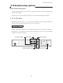
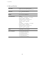
5. Extended setup options (30-33)
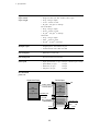
Interface type
The parallel interface or the serial interface is selected. When this function is executed, the
printer is initialized. See "Connecting the computer" on page 12 for correct selection and
connection of the interface cable.
30 INTERFACE
I/F: PARALLEL
I/F: SERIAL
I/F: AUTO
....................
Parallel and serial interface are switched
automatically.
Parity bit (serial interface)
This function selects the appropriate parity bit in the transmission data frame.
31 PARITY BIT
PARITY: NONE
PARITY: ODD
PARITY: EVEN
Data length (serial interface)
This function selects the appropriate data length.
32 DATA LENGTH
LENGTH: 8 BITS
LENGTH: 7 BITS
Stop bit (serial interface)
This function selects the appropriate number of stop bits.
33 STOP BIT
STOP BIT: 1 BIT
STOP BIT: 2 BIT
47
5. Extended setup options (34-36)
Communication protocol (serial interface)
This function selects the appropriate communications protocol. Refer to the specification of
your host system for selecting proper communication protocol.
34 PROTOCOL
DTR
XON/OFF1
XON/OFF2
ETX/ACK
....................
....................
....................
Busy/Ready protocol
Set XON/XOFF 1.
Set XON/XOFF 2.
Note: The XON/XOFF 1 differs from the XON/XOFF 2 in that the XON code (11h) is sent
from the printer at power-on in the XON/XOFF 1 protocol.
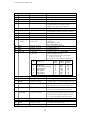
Communication speed (serial interface)
This function selects the appropriate baud rate for the data transmission speed.
35 BAUD RT
SPEED:
SPEED:
SPEED:
SPEED:
9600
4800
2400
1200
BPS
BPS
BPS
BPS
Serial error check (serial interface)
This function selects the printer's response to a serial data transmission error. The serial data
transmission error includes a parity error, framing error, and over-run error. If "PRINT" is
enabled, the data in error is printed as an asterisk(*). If "IGNORED" is enabled, the data in
error is discarded.
36 SERIAL ERROR
S.ERROR: PRINT
S.ERROR:IGNORED
48
5. Extended setup options (37-39)
CTS signal (serial interface)
This function accepts or ignores the CTS (Clear to Send) signal from the host.
37 CTS ENABLE
CTS:
CTS:
NO
YES
........... Ignores the CTS signal
........... Functions according to the CTS signal from the host
DSR signal (serial interface)
This function accepts or ignores the DSR (Data Set Ready) signal from the host.
38 DSR ENABLE
DSR:
DSR:
NO
YES
........... Ignores the DSR signal
........... Functions according to the DSR signal from the host
CD signal (serial interface)
This function accepts or ignores the CD (Carrier Detect) signal from the host.
39 CD ENABLE
CD:
CD:
NO
YES
........... Ignores the CD signal
........... Functions according to the CD signal from the host
49
5. Extended setup options (40-42)
Communication buffer size
This function selects the maximum size of the input buffer. An appropriate selection is
displayed according to another setup options like the emulation type of either IBM or FX mode.
When the selection of this function is completed, the printer is intialized.
The buffer size affects the signal protocol in serial data communication. In these protocols the
printer's busy/ready state changes according to the data remaining values in the buffer.
1
Ready to busy (CIN)
B.SIZE:20KBor8KB
1k bytes
B.SIZE:128B
32 bytes
Busy to ready (CRN)
2k bytes
64 bytes
40 BUFFER SIZE
B.SIZE:20KB
B.SIZE:8KB
B.SIZE:128B
....................
....................
....................
FX, BP-A/I mode
IBM mode
Minimum input buffer size in any mode
Setting of whether ERROR/PE signals are output or not.
(1)
(2)
Setting is made whether or not ERROR and PE signals for the parallel interface are output.
When "NO" is selected, ERROR signal remains HIGH, and PE signal remains LOW, in any
situation.
41 ERROR STATUS
STATUS SIG.:YES
STATUS SIG.:NO
Print direction
Selects either pre-directional printing, bi-directional printing, or uni-directional printing.
42 PRINT DIR
PRE-DIRECTION
UNI-DIRECTION
BI-DIRECTION
....................
....................
Default print direction
Ignores the software command (ESC U).
• Pre-directional printing:
Whenever a double pass of the print head is required, the direction of the second pass is the
same as that of the first pass. This logic-seeking, unidirectional printing can be used,
therefore, in modes such as double strike and double height printing. The logic seeking
capability is executed before the first pass of the print head. The printing direction of all paths
is the same as that of the first pass.
• Bi-directional printing:
Successive passes of the print head alternate between the left-right and right-left direction.
• Uni-directional printing:
Data is always printed in a single direction from the left to the right. This selection on the
front panel will ignore a software print direction command.
When unidirectional printing is set, a software command with respect to the printing direction
is not accepted. When pre-directional printing or bidirectional printing is set, a software
bidirectional command is executed.
50
5. Extended setup options (43-45)
Invert LCD display
This function sets up-side down text display in the LCD. Use with the reverse control panel
sheet. (See page 7)
43 INVERT DISP
INVERT:
INVERT:
NO
YES
Setting of ENERGY STAR
(1)
(2)
Set the power conservation standby mode.
When this mode is valid, if the HC and (or) LF motors stop, the current to HC, LF,
FAN, and the ribbon motor is interrupted 14 minutes later then the standby power
conservation mode is engaged. Switching to the normal mode is effected when any
mechanical action is required.
44 SLEEP MODE
SLEEP MODE:YES
SLEEP MODE:NO
Saving user setup options
This function saves the current setup into one of three memory areas.
Press the ENTER key to store the current setup in the desired memory area. This does not
affect the current setting.
45 SAVE SETUP
SETUP: MEM1
SETUP: MEM2
SETUP: MEM3
51
5. Extended setup options (46)
Restore factory default setups
This function selects to initialize the printer to the factory setting. Press the ENTER key to
restore the factory setting in all setup options, Otherwise; press any other key to cancel this
option. "SETUP : COMPLETED" is displayed at the completion of the execution.
46 FACTORY ST
PRESS ENTER SW
Option Menu
<Basic options>
1. FONT
2. CHAR PITCH
3. PAGE (FANFOLD)
4. PAGE (SINGLE)
5. MULTIPART
6. SELECT SETUP
7. SETUP LISTING
<Extended options>
1. LOADING ADJUST
2. PAPER WIDTH
3. LINE WIDTH
4. LF PITCH
5. OVERRIDE PRINT
6. AUTO SCROLL
7. LABEL MODE
8. DEFAULT PG LNG
9. P.OUT DETECT
10. P.OUT BUZZER
11. 1-INCH SKIP
12. LF SPEED
13. CSF OPTION
14. EMULATION
15. NATIONAL FONT
16. CODE PAGE
17. EURO SYMBOL
18. ZERO STYLE
19. CHARACTER SET
20. CR SETTING
....................
"SETUP: COMPLETED" is displayed immediately
after pressing the ENTER key.
Factory Default
DRAFT
CODE (10 CPI)
CODE (11")
CODE (A4 PORT)
NORMAL
CURRENT
17/72"
SINGLE: <9"
FANFOLD: ≥9"
13.6"
CODE (6 LPI)
NO
NO
NO
11"
YES
YES
NO
NORMAL
NO
FX MODE
USA
437
NO
NO-SLASH
ITALIC
AUTO FEED
Option Menu
Factory Default
21.
22.
23.
24.
25.
26.
27.
29.
30.
31.
32.
33.
34.
35.
36.
37.
38.
39.
40.
41.
42.
43.
44.
45.
46.
47.
48.
CR+LF
WITH PRINT
YES
COUNTRY
CODE
CODE
MODE1
1
PARALLEL
NON
8 BITS
1 BIT
DTR
9600 BPS
PRINT
NO
NO
NO
MAXIMUM
YES
PREDIRECTION
NO
YES
52
LF SETTING
VT SETTING
20CPI SETTING
DWNLD CHR.SET
ITALIC
BOLD
BARCODE
BC SIZE
INTERFACE
PARITY BIT
DATA LENGTH
STOP BIT
PROTOCOL
BAUD RT
SERIAL ERROR
CTS ENABLE
DSR ENABLE
CD ENABLE
BUFFER SIZE
ERROR STATUS
PRINT DIR
INVERT DISP
SLEEP MODE
SAVE SETUP
FACTORY SET
SOFTWARE SET.
RESET LOCK
NO
NO
5. Extended setup options (47-48)
Software controlled setup
This function enables or disables a control on the setup options from the specially provided
software command. See "Printer setup command codes" section in Appendix B.
47 SOFTWARE SET
SOFTWARE:
SOFTWARE:
NO
YES
Lock the RESET key
This function locks up the RESET key during the online mode in order to avoid an accidental
reset during printing.
48 RESET LOCK
LOCK:
LOCK:
NO
YES
53
6. Selection of printer driver
6. Selection of printer driver
About printer driver
Printer Driver is a section of your software that automatically translates instructions from the
software to your printer.
For example, when using some application software, if you want to boldface or underline a
word, the printer driver automatically translates your specific boldface or underline instruction
on your application software to printer control command.
Different printers use different control codes for designating print styles. Therefore, it is
important that when you install your software, you select the appropriate printer driver
designed for your printer.
When WINDOWS 3.1, WINDOWS NT 4.0, or WINDOWS 95, 98 is used, please install the
Printer Driver in the attached Floppy Disk to WINDOWS.
When this printer in the MS-DOS or other environment, such as UNIX or OS/2, proceed as
follows.
Printer driver selection
Select a suitable printer driver from the list of supported printers. This would include either
the Epson FX-1050 or IBM Proprinter III XL. Each of these printer drivers should allow
you to access many of the features on your printer.
If this printer is not listed, look for the following printer drivers. While this should allow you
to print your document with your printer, it probably will not allow you to access the many
features of the printer. A few of the choice you may see are given below in order of
preferences.
FX or IBM mode:
SEIKO Precision
(15" printer driver)
(10" printer driver)
BP-A or BP-I mode:
SEIKO Precision
BP-5460
BP-5420
Epson
FX-1050
FX-286e
EX-1000
FX-286
FX-185
FX-100+
FX-100
FX, LX, MX
FX-850
FX-86e
EX-800
FX-85
IBM
Proprinter III XL
Proprinter II XL
Proprinter XL
Proprinter III
Proprinter II
Proprinter
Graphics Printer
Epson
FX (BP-A)
IBM
Graphics Printer (BP-I)
Note:
Set the emulation type in the extension setup options accordingly to the selection of printer driver.
For example, Epson FX-1050 printer driver selection should set the emulation type to FX mode.
54
7. Troubleshooting
7. Troubleshooting
If an error occurs during printing, you will get several warnings. A buzzer sounds, P.OUT
lamp blinks, and an error message appears in the display window of the front control panel.
❏ Error Messages
Error Message
Cause and Solution
CARRIAGE ERROR
The printer cannot detect the print head position.
◆ Turn off the printer immediately. After a brief wait, turn
the printer on again.
RAM ERROR
Internal RAM does not function properly.
◆ Turn the printer off and back on again. If the error persists,
consult your dealer.
EEPROM ERROR
Checksum error occurred in EEPROM IC chip.
◆ Reset the error status by the following procedure:
Hold down the PARK, TOF SET, M.LF, and LF keys all
together while turning on the power to the printer. If the
error persists, consult your dealer.
WARNING:
All registered settings in the printer will be cleared, e.g.
settings in setup options and in vertical alignment data.
You will have to make re-adjustment (see page 61).
FAN ERROR
Abnormal fan operation is detected.
HEAD PROTECTION
(ON LINE indicator blinks.)
Long continuous printing may overheat the print head.
◆ The printer stops temporarily and restarts automatically
when the print head temperature lowers to a safe level.
PAPER ERROR
(Buzzer sounds 3 times.)
Paper jam or improper paper operation occur.
◆ If paper parking is not completed, press the PARK key.
Otherwise reload the paper.
PAPER OUT
Paper is not loaded in the printer.
◆ Load paper (pages 13 and 14).
COVER OPEN
One of the printer covers are open.
◆ Close the cover to restart the operation.
POWER DOWN!!
Abnormal current is detected.
◆ The printer is automatically turnoff.
Stop using the printer, and contact the dealer.
55
7. Troubleshooting
❏ Problem guide
Problem
Cause and Solution
POWER lamp fails to light
◆
◆
Power cord and power connection fail.
Blown fuse in the printer.
Printer stops or slows
down on printing
◆
Print head has overheated. Wait until it has cooled down.
P.OUT lamp lights
incorrectly
◆
◆
Paper detect sensor may be damaged.
Sensor hole is clogged.
Poor quality printing or
smudging of the paper
◆
◆
◆
Old or worn out ink ribbon needs to be replaced.
Print head adjustment lever is not set correctly.
Print head may need to be cleaned or replaced.
Some characters miss
printing
◆
Ribbon cassette is not properly installed.
Incorrect character
printed
◆
Host system control and data code may not match the
printer's setup.
Paper not advancing
◆
Incorrect friction lever setting.
Fanfold paper slips
◆
◆
Stack of fanfold paper behind the printer is placed
crookedly.
Friction lever is in the cut sheet setting.
Extra line feed
◆
The carriage return sub-menu selection is set incorrectly.
Paper jam
◆
◆
Paper is curled.
Move friction lever to the fanfold paper setting and
carefully remove the jammed paper.
Paper Bail abnormal
operation
◆
Electric Noise on the printer. Turn OFF the printer and wait
until all the electric noises are discharged from the printer
(one minute), and then turn it back ON again. Consult your
dealer if the error persists.
56
7. Troubleshooting
❏ Input Hexadecimal Dump Mode
The Input hexadecimal dump capability of the printer enables monitoring of data as it is sent to
the printer. Each Escape Sequence, Control Code, and ASCII character sent from the computer
to the printer is output in a two-digit hexadecimal format. Such printing is initiated after 16
bytes of data have been transmitted to the printer. Hexadecimal values and their corresponding
ASCII characters between the values 20h to 7Eh are printed on each line.
L
C
PARK
TOF SET
EXIT
ENTER
SETUP
BIN
D
RESET
M.LF
LF
FF
M.RLF
RLF
TEAR OFF
POWER
ON LINE
P.OUT
ON LINE
To run this mode in draft printing
Press the FF key while turning ON the printer or pressing the RESET key. Hold down the FF
key until the LCD displays "HEXDUMP"
To run this mode in NLQ printing Press the FF and ONLINE keys simultaneously while turning
ON the printer or pressing the RESET key. Hold down the FF and ONLINE keys until the
LCD displays "HEXDUMP"
To terminate this mode
Press the RESET key or turn off the power.
Example
10
20
30
40
50
60
70
00000
00010
REM HEXADECIMAL DUMP LIST EXAMPLE
OPEN "LPT1:"AS #1
WIDTH #1,255
PRINT #1,"ABC";CHR$(13);CHR$(10);
PRINT #1,"123";CHR$(13);CHR$(10);
PRINT #1,"HENRY IS HANDSOME"
END
41 42 43 0D 0A 31 32 33
49 53 20 48 41 4E 44 53
0D 0A 48 45 4E 52 59 20
4F 4D 45 0D
ABC..123..HENRY
IS HANDSOME.
Note
ASCII characters are printed according to hexadecimal codes of the data. Codes
other than 1Bh and 20h to 7Eh are printed as “.” (2Eh). For the code 1Bh, “IE ” is
printed in draft mode and “ ESC” is printed in NLQ mode.
57
8. Maintenance
8. Maintenance
❏ Cleaning
Minimum periodical cleaning will ensure the maximum performance from your printer. Do not
spill or splash a cleaning liquid inside the printer. Please refer to the "Printer cover removal"
on page 59 to remove the covers for cleaning.
Note
Before cleaning the printer, be sure to turn off the power and disconnect the
power cord. (When cleaning the platen, power may be required.)
Platen
◆
Use a platen cleaner, or any weak alcohol solvents, to remove any
ink from the platen and bail rollers. Do not apply any other liquid
chemical to the platen.
Note
Even with a specified platen cleaner, frequent use of the liquid is
not recommended. Apply only when it is necessary.
Inside the printer
◆
Use a vacuum cleaner to remove paper dust and particles from
inside the printer. A small brush is suitable for removing paper
dust from hard-to-get-at areas.
Exterior Casing
◆
Clean with a soft cloth dampened with a mild detergent. Never
use organic solvents such as alcohol or thinner.
FPC cable plastic binder
Make sure that the binder clamps the cable securely.
Exterior Casings
Clean with a soft cloth dampened
with a mild detergent.
Inside the printer
Thoroughly vacuum these area.
Remove any collected paper dust and particles.
58
8. Maintenance (Lubrication)
❏ Lubrication
In the case of heavy use of the printer, apply a specified lubricating oil only to the front and
rear metal carriage bar. When applying the lubricant to the carriage bars, spread the oil by
manually moving the print head back and forth along the carriage bar.
Consult your dealer to obtain the recommended lubricating oil. Do not use an unspecified oil,
or it may reduce the printer's performance drastically.
Oiling
Clean thorougly with a dry cloth,
then apply specific type of lubricants:
Cosmo Hydro (HV#22) recommended.
Front bar
Rear bar
❏ Printer cover removal
Rear Top Cover Removal
Stopper
Stopper
59
◆ Remove the Rear Cover.
Open the Rear Cover to the level
position and pull it.
◆ Remove the two Stoppers for the Rear
Top Cover.
Detach the two screws to remove the
two Stoppers.
◆ Remove the Rear Top Cover.
Slide the Rear Top Cover toward the
rear and raise it to vertical position and
lift straight upward.
8. Maintenance (Printer cover removal)
Guide
Printer Cover
◆
Open the front cover to an upright
position, then lift and remove the
cover.
Pivot
Rear Cover
◆
Open the rear cover from the
bottom edge and pull it toward the
bottom to remove.
Paper Rack
◆
Slide both paper guides to the
extreme left and right edges of the
paper rack. Raise the rear end to
stand vertically and lift straight
upward to remove.
Sound Seal Cover
◆
L-angle Hinge
60
Push out on the outer edge of the
sound seal cover where it connects
to the L-angle from the printer
while pushing the stud of the Langle out of the hole. Then remove
the whole cover.
8. Maintenance (Vertical alignment mode)
❏ Vertical alignment mode
The vertical alignment mode serves to compensate for the slippage of the vertical printing
positions, that occurs due to individual differences and age distortion of the printer.
Print mode
Character mode family
MODE 0
Draft pica
Speed draft (SD), super speed draft (SSD), single
density graphic, double speed/double density
graphic
MODE 1
Draft elite
979-dot graphics
MODE 2
NLQ pica
Draft condense (15 CPI, 17.1 CPI, 20 CPI), double
density graphic, quadruple density graphic, 1088dot graphic, 1224-dot graphic
MODE 3
NLQ elite
1958-dot graphic
MODE 4
NLQ condensed (20 CPI)
NLQ condense (15 CPI, 17.1 CPI, 20 CPI)
Operation and printing pattern
Before performing the adjustment mode, make sure the ribbon cassette and at least 10-inch
wide paper are properly installed in the printer.
Select pattern No.
Exit alignment mode
L
C
D
RESET
PARK
TOF SET
EXIT
ENTER
SETUP
BIN
Enter alignment mode
M.LF
LF
FF
M.RLF
RLF
TEAR OFF
POWER
ON LINE
P.OUT
ON LINE
Set printing conditions
1. Press the SETUP and BIN keys simultaneously while turning ON the printer or pressing the
R E S E T k e y. H o l d d o w n t h e b o t h S E T U P a n d B I N k e y s u n t i l t h e L C D d i s p l a y s
"ALIGNADJUST".
SETUP key + BIN key + Power ON (or RESET key)
2. Seven patterns from +3 to -3 in the mode 0 are printed in accordance with the printing
conditions. The pattern of the present printing condition is printed at position 0 (zero).
3. After the patterns are printed and the friction lever is set to the fanfold setting, the paper is
automatically scrolled. When the friction lever is set to the cut sheet setting, the form feed
operation takes place and the LCD indicates “SELECT GRADE: 0”.
SELECT GRADE: 0
61
8. Maintenance (Vertical alignment mode)
PRINTED PATTERNS EXAMPLE
Description of Patterns
The printer has 13 preprogrammed patterns in each mode from which only seven
patterns are printed. The pattern "****..." indicates out-of-range. Consult your
dealer if you cannot find correct pattern.
4. Judging from the printed pattern in each print mode, select the grade number of a best aligned
pattern between +3 and -3.by pressing the Left and Right arrow keys.
5. Press the ENTER key to set the printing condition. Printing for the next mode automatically
starts.
6 Repeat the steps 4 and 5 for modes 1 through 4.
7 After all adjustment is completed, the LCD displays "PRESS RESET SW". By pressing the
RESET key, the printer exits from this vertical alignment mode.
62
A. Specifications
Appendix A. Specifications
❏ Printing specifications
Printing method
• Impact dot matrix and bidirectional logic seeking printing
Print Head
• 18 pins (4 rows in parallel)
Emulation
• Epson FX-1050
• IBM Proprinter III XL
• BP-5460 FA
Resident fonts
• S.Roman, Sans Serif, Draft, Speed draft, Super speed draft
Character sets
• Epson character sets
• IBM character sets and code pages
• SPI character sets
Graphic printing
8
•
•
•
•
•
•
•
modes (8 or 9 pin graphics) — dpl: dot per line
816 dpl ( 60 dpi)
979 dpl ( 72 dpi)
1088 dpl ( 80 dpi)
1224 dpl ( 90 dpi)
1632 dpl (120 dpi)
1958 dpl (144 dpi)
3264 dpl (240 dpi)
Print mode
Character spacings
• 10cpi Pica print mode
• 12cpi Elite, Speed draft print mode
• 15cpi Semi-condensed draft, Super speed draft print mode
• 17.1cpi Condensed draft print mode
• 20cpi Condensed elite print mode
• Proportional print mode
Throughput
• Draft (10cpi):
• NLQ (10cpi):
183 lpm
38 lpm
Evaluation conditions:
Data of 100 lines by 132 columns, all a ASCII rolling
pattern characters, and 1/6-inch line feed is input from a
host and is stored in the 20K-byte communication buffer of
the printer. With that condition, the number of printing lines
per minute is measured.
63
A. Specifications
Paper feed method
Paper width
Paper weight
Friction method:
• Single cut sheet (A3, B4, A4, B5, letter, legal)
• 55 kg - 90 kg in Japan
• 17 lbs. - 28 lbs. in USA
• 64 g/m 2 - 105 g/m 2 in Europe
Tractor method:
• 45 kg - 90 kg in Japan
• 14 lbs. - 28 lbs. in USA
• 53 g/m 2 - 105 g/m 2 in Europe
CSF mode:
• 55 kg - 70 kg in Japan
• 15lbs. - 21 lbs. in USA
• 60 g/m 2 - 81 g/m 2 in Europe
Multiple copies
• Original plus 6, non-carbon, 34 g/m 2
• Total thickness of less than 0.41 mm
Line feed pitch
• Minimum of 1/216 inch
Line feed speed
• 60 lines/second (6 lines/inch)
Print speed
•
•
•
•
Super Speed Draft (15 cpi): 840 cps (character per second)
Speed Draft (12 cpi):
672 cps
Draft Pica (10 cpi):
560 cps
NLQ Pica (10 cpi):
138 cps
Recommended
print area
Single sheet Paper
Fanfold Paper
TOF
Print
recommended
area
for single sheets
Loading adjust
17/72inch (6mm)
Override print
17mm OFF
8 mm ON
Print
recommended
area
for
continuous form
Perforation
Near perforation
1 inch (25.4mm)
Final form
13 mm
64
Override print
17mm
OFF
8mm
ON
13 mm
A. Specifications
Character
Spacing
Print mode
Draft
Dot Spacing Max No. Character Printing
H x V
of
Structure Speed
(inches)
Columns (V x H)
(cps)
Pica
10 cpi
1/120
x
1/72
136
12
x
9
560
Elite (Epson)
12 cpi
1/120
x
1/72
163
10
x
9
672
Elite (IBM)
12 cpi
1/144
x
1/72
163
12
x
9
556
15 cpi
1/180
x
1/72
204
12
x
9
416
Condensed pica
17 cpi
1/240
x
1/72
233
14
x
9
476
Condensed elite
20 cpi
1/240
x
1/72
272
12
x
9
556
Speed Draft
12 cpi
1/120
x
1/72
163
10
x
9
672
Super Speed Draft
15 cpi
1/120
x
1/72
204
8
x
9
840
Near
Letter
Quality
Pica
10 cpi
1/240
x
1/144
136
24
x
18
138
Elite (Epson)
12 cpi
1/240
x
1/144
163
20
x
18
166
Elite (IBM)
12 cpi
1/288
x
1/144
163
24
x
18
138
15 cpi
1/360
x
1/144
204
24
x
18
104
Condensed pica
17 cpi
1/480
x
1/144
233
28
x
18
119
Condensed elite
20 cpi
1/480
x
1/144
272
24
x
18
138
(dpl)
Graphics
Standard density
1/60
Double density
1/120
Double speed,
Double density
(dps)
1/72
816
n
x
8 or 9
3360
x
1/72
1632
n
x
8 or 9
3333
1/120
x
1/72
1632
n
x
8 or 9
6720
Quadruple density
1/240
x
1/72
3264
n
x
8 or 9
6666
979 dot
1/72
x
1/72
979
n
x
8 or 9
3333
1088 dot
1/80
x
1/72
1088
n
x
8 or 9
2222
1224 dot
1/90
x
1/72
1224
n
x
8 or 9
2500
1958 dot
1/144
1/72
1958
n
x
8 or 9
3333
High density
1/120
1/144
1632
16
3333
65
x
x
x
n
x
A. Specifications
❏ Parallel interface specifications
• Input connector
1817 1615141312 1110 9 8 7 6 5 4 3 2 1
3635 3433323130 2928 2726252423 22 212019
PIN
1
2
3
4
5
6
7
8
9
10
11
12
13
14
15
16
17
18
SIGNAL
STROBE
DATA 1
DATA 2
DATA 3
DATA 4
DATA 5
DATA 6
DATA 7
DATA 8
ACK
BUSY
PE
SELECT
AUTOFEED
NC
NC
CHASSIS GND
+5 V (max. 200mA)
Notes:
IN/OUT
IN
IN
IN
IN
IN
IN
IN
IN
IN
OUT
OUT
OUT
OUT
IN
PIN
19
20
21
22
23
24
25
26
27
28
29
30
31
32
33
34
35
36
SIGNAL
GND
GND
GND
GND
GND
GND
GND
GND
GND
GND
GND
GND
INITIAL
ERROR
NC
NC
NC
NC
1. HIGH is pulled up to + 5V by 2.2k Ω resistor.
2. NC stands for no connection.
3. CHASSIS GND and GND are connected in the printer.
• Data input timing chart
STROBE
1 - 50 µs
DATA 1 -DATA 8
min. 1 µs
min. 1 µs
BUSY
max. 0.5 µs
ACK
3 - 7 µs
3 - 7 us
6 - 10 µs
min. 0 µs
66
IN/OUT
IN
OUT
A. Specifications
❏ Serial interface specifications
• Input connector
1
13
25
14
RS-232C Pin assignments
PIN
1
2
3
4
5
6
7
8
9
10
11
12
13
Notes:
SIGNAL
CHASSIS GND
TXD
RXD
RTS
CTS
DSR
SIGNAL GND
CD
NC
NC
SRTS
NC
NC
IN/OUT
OUT
IN
OUT
IN
IN
IN
OUT
PIN
14
15
16
17
18
19
20
21
22
23
24
25
SIGNAL
NC
NC
NC
NC
NC
NC
DTR
NC
NC
NC
NC
NC
1. NC stands for no connection.
2. CHASSIS GND and GND are connected in the printer.
• Handshake protocol
One of the following four protocols can be selected:
- DTR protocol
- X ON/X OFF protocol I
- X ON/X OFF protocol II
- ETX/ACK protocol
• Baud Rate
In the setup options, one of the following baud rates can be selected:
1200, 2400, 4800, and 9600 BPS.
67
IN/OUT
OUT
A. Specifications
❏ Other specifications
Power supply
• 120VAC : For USA, Canada and Taiwan
• 230VAC : For Asia, Oceania, Europe and others
Temperature
• 41°F - 104°F (during Operation)
• 5°C - 40°C
Humidity
• 20 % - 80 % (no condensation)
External dimensions
Model A
• 24.4"(Width x 10.2"(Height) x 12.0"(Depth)
• 620(W) x 260(H) x 305(D) mm
• With the paper rack and sound seal cover
24.4"(W) x 11.6"(H) x 17.5"(D)
620(W) x 295(H) x 445(D) mm
Model B
• 24.4"(Width) x 10.2"(Height) x 13.0"(Depth)
• 620(W) x 260(H) x 330(D) mm
• With the paper rack and sound seal cover
24.4"(W) x 11.6"(H) x 18.5"(D)
620(W) x 295(H) x 470(D) mm
Weight
• Approximately 44.1 lbs. [20 kg]
Power Consumption
• 160 watts (during LQ self test)
2.1A (120VAC), 1.2A (230VAC)
• 45 watts (during stand-by)
0.6A (120VAC), 0.4A (230VAC)
• 12 watts (sleeping mode)
0.3A (120VAC), 0.2A (230VAC)
68
B. Control code summary (IBM)
Appendix B. Control code summary
❏ IBM mode
ITEM
[1]
[2]
[3]
SYMBOL
BEL
BS
HT
Hexadecimal & Decimal
[07] H [7] D
[08] H [8] D
[09] H [9] D
FUNCTION
Activates the alarm.
Backspace one character.
Moves to next horizontal tab.
[4]
[5]
[6]
[7]
[8]
[9]
[10]
[11]
[12]
[13]
[14]
LF
VT
FF
CR
SO
SI
DC1
DC2
DC4
CAN
ESC EM n
[0A] H [10] D
[0B ]H [11] D
[0C] H [12] D
[0D] H [13] D
[0E] H [14] D
[0F] H [15] D
[11] H [17] D
[12] H [18] D
[14] H [20] D
[18] H [24] D
[1B,19,n] H [27,25,n] D
[15]
ESC – n
[1B,2D,n] H [27,45,n] D
[16]
[17]
[18]
[19]
[20]
[21]
ESC 0
ESC 1
ESC 2
ESC 3 n
ESC 4
ESC 5 n
[1B,30] H [27,48] D
[1B,31] H [27,49] D
[1B,32] H [27,50] D
[1B,33,n] H [27,51,n] D
[1B,34] H [27,52] D
[1B,35,n] H [27,53,n] D
[22]
[23]
[24]
[25]
ESC 6
ESC 7
ESC :
ESC = n1 n2
m c a1 a2 data
[1B,36] H [27,54] D
[1B,37] H [27,55] D
[1B,3A] H [27,58] D
[1B,3D,n1,n2,m,c,a1,a2,data] H
[27,61,n1,n2,m,c,a1,a2,data] D
Linefeeds after printing.
Linefeeds to next vertical tab position after printing.
Form feeds after printing.
Carriage return after printing.
Sets double width character mode for 1 line.
Sets condensed character mode.
Selects printer that has been deselected by ESC Q.
Selects pica (10 cpi) character mode.
Cancels double width character mode set by SO.
Clears data in buffer.
Controls Cut Sheet Feeder.
n=0 : Manual feeding.
n=1 : Selects Bin 1.
n=2 : Selects Bin 2.
n=R : Ejects a cut sheet paper loaded in the printer.
Sets or cancels underline mode.
n=0 : underline is cancelled.
n=1 : underline is set.
Sets line spacing to 1/8".
Sets line spacing to 7/72".
Linefeeds with the line spacing set by ESC A.
Sets line spacing to n/216" (1≤n≤255).
Sets the current print position as top-of-form (TOF).
Sets/cancels auto linefeed with CR
n=0 : Carriage return without linefeed.
n=1 : Carriage return with linefeed.
Selects IBM character set 2.
Selects IBM character set 1.
Sets elite (12 cpi) character mode.
Defines download character.
When n1=n2=0, the download area is cleared.
Total number of data in download characters is defined
as n1 + n2 x 256. Each character consists of assign
code (c), attributes (a1 and a2), and data.
ESC = NUL NUL .clears download area.
Download characters can be selected for printing or
for a storage memory by ESC I command.
m=14h indicates a draft download character and
m=15 ha NLQ download character.
69
B. Control code summary (IBM)
ITEM SYMBOL
Hexadecimal Decimal
Draft download
FUNCTION
m=14h indicates a draft download character.
Attribute (a1)
8(h) x 11(W) dots
Offset
b7 b6 b5 b4 b3 b2 b1 b0
String length
00: 8x11 dots
01: 12x11 dots,
line 8 is copied to lines 9-12
10: 12x11 dots,
lines 1-4 are copied to lines 9-12
1
2
3
0: ascender (pins 1-8)
1: descender (pins 2-9)
4
5
Attribute (a2)
6
b7 b6 b5 b4 b3 b2 b1 b0
7
8
1
2
3
4
5
6
7
8
String length (1-11)
Offset (0-10)
9 10 11
Data = d1-d11
d7
NLQ download
m=15h indicates a NLQ download character.
16(h) x 23(W) dots
Attribute (a1)
b7 b6 b5 b4 b3 b2 b1 b0
00: 16x23 dots
01: 24x23 dots, lines 15-16 are copied
to lines 17-24
10: 24x23 dots, lines 1-8 are copied to
lines 17-24
1
5
10
15
20
Attribute (a2) = Don't care
Data = d1-d23
[26]
ESC A n
[1B,41,n] H [27,65,n] D
[27]
[28]
ESC B n1 n2...
n64 NUL
ESC C n
[1B,42,n1,n2,...n64,00] H
[27,66,n1,n2,...n64,0] D
[1B,43,n] H [27,67,n] D
[29]
ESC C NUL n
[1B,43,00,n] H [27,67,0,n] D
[30]
ESC D n1
n2...n28 NUL
[1B,44,n1,n2,...n28,00] H
[27,68,n1,n2,...n28,0] D
[31]
[32]
[33]
[34]
ESC E
ESC F
ESC G
ESC H
[1B,45] H
[1B,46] H
[1B,47] H
[1B,48] H
[27,69] D
[27,70] D
[27,71] D
[27,72] D
70
23
d16
1st byte
2nd byte
Sets line spacing to n/72" (1≤n≤255)
This command becomes effective by ESC 2.
Sets vertical tab positions beginning from n1 and end
with NUL [00]H. n=1 is the second line from TOF.
Sets page length in line unit (1≤n≤255).
The current print line becomes TOF (top of form).
Sets page length in inch unit (1≤n≤151).
The current print line becomes TOF (top of form).
Sets horizontal tab position (1≤n≤255).
n indicates the number of spaces from the left margin
with the character width at the command execution.
n=1 is at the first character from the left margin.
Sets emphasized character mode.
Cancels emphasized character mode.
Sets double strike character mode.
Cancels double strike character mode.
B. Control code summary (IBM)
ITEM SYMBOL
[35]
ESC I n
Hexadecimal Decimal
[1B,49] H [27,73] D
FUNCTION
Selects one of font styles.
n=0 : Draft 10 cpi
n=1 : Speed draft 12 cpi
n=2 : NLQ (Sans Serif)
n=3 : NLQ (Roman)
n=4 : Draft download
n=5 : Speed draft download
n=6 : NLQ (Sans Serif) download
n=7 : NLQ (Roman) download
n=11 : NLQ (Roman) italic
Linefeeds in various spacings in n/216" (1≤n≤255).
[36]
ESC J n
[1B,4A,n] H [27,74,n] D
[37]
ESC K n1 n2
data
[1B,4B,n1,n2,data] H
[27,75,n1,n2,data] D
Prints the 8-pin standard-density graphics (60 dpi).
The total number of dots in the data is set by
n1 + n2 x 256.
[38]
ESC L n1 n2
data
[1B,4C,n1,n2,data] H
[27,76,n1,n2,data] D
Prints the 8-pin double-density graphics (120 dpi).
The total number of dots in the data is set by
n1 + n2 x 256.
[39]
ESC N n
[1B,4E,n] H [27,78,n] D
[40]
[41]
ESC O
ESC P n
[1B,4F] H [27,79] D
[1B,50,n] H [27,80,n] D
[42]
ESC Q n
[1B,51,16] H [27,81,22] D
[43]
ESC R
[1B,52] H [27,82] D
[44]
ESC S n
[1B,53,n] H [27,83,n] D
[45]
[46]
ESC T
ESC U n
[1B,54] H [27,84] D
[1B,55,n] H [27,85,n] D
[47]
ESC W n
[1B,57,n] H [27,87,n] D
[48]
ESC X n m
[49]
ESC Y n1 n2
data
[1B,5C,n,m] H
[27,92,n,m] D
[1B,59,n1,n2,data] H
[27,89,n1,n2,data] D
[50]
ESC Z n1 n2
data
[1B,5A,n1,n2,data] H
[27,90,n1,n2,data] D
Sets bottom margin (1≤n≤255).
n specifies the number of lines not to be printed at the
end of a page.
For example: If the line spacing is 1/6 inch and the page length is 66 lines,
an ESC N 6 command causes the printer to print 60 lines, then skip 6 lines.
The space to be skipped is 1 inch (1/6 inch x 6).
Cancels bottom margin set by ESC N command.
Sets/cancels proportional mode
n=0 : Cancels proportional mode.
n=1 : Sets proportional mode.
Deselects the printer. DC1 selects the printer.
n=16h : Deselects the printer.
n≠16h : Ignores this command.
Initializes horizontal tabs to every 8th column and
clears vertical tabs.
Sets superscript or subscript character mode.
n=0 : the superscript character mode is set.
n=1 : the subscript character mode is set.
Cancels super-/subscript character mode.
Selects unidirectional or bidirectional printing.
n=0 : bidirectional printing is set.
n=1 : unidirectional printing is set.
Sets or cancels double width character mode.
n=0 : the double width character mode is cancelled.
n=1 : the double width character mode is set.
Sets left and right margins (0≤n<m≤255)
n: left margin, m:right margin.
Prints 8-pin double-speed double-density graphics
(120 dpi). The total number of dots in the data is
set by n1 + n2 x 256.
Prints 8-pin quadruple-density graphics (240 dpi).
The total number of dots in the data is set by
n1 + n2 x 256.
71
B. Control code summary (IBM)
ITEM SYMBOL
[51]
ESC [ @ n1 n2
m1...m4
[52]
ESC [ K n1 n2
m1 m2 m3 m4
Hexadecimal Decimal
[1B,5B,2D,n1,n2,m1,..,m4] H
[27,91,45,n1,n2,m1,..,m4] D
[1B,5B,4B,n1,n2,m1,..,m4] H
[27,91,75,n1,n2,m1,..,m4] D
m1
m2
Code
00h, 04h, FEh
01h, 05h, FFh
03h
FUNCTION
Sets single or double height/width/line-spacing mode.
n1=4, n2=0, m1=0, and m2=0.
m3=01h : single character height.
m3=02h : double character height.
m3=10h : single line spacing.
m3=20h : double line spacing.
m3=22h : double character height/line spacing.
m4=01h : single character width.
m4=02h : double character width.
Software initialization.
The number of data bytes following n2 is defined as
n1 + n2 x 256.
Initialize condition
Initialize without clearing download area
Initialize with clearing download area
Fixed value
m3 and m4
Indicates the combination of each parameters:
m3
m4
bit7 valid (0) or invalid (1) of m3
valid (0) or invalid (1) of m4
bit6
—
USA (0) or Multilingual (1)
bit5 Alarm on (0) or off (1)
Pre (0) or Unidirectional (1)
bit4 LF=LF (0) or LF=CR+LF (1)
20 cpi valid (0) or invalid (1)
bit3 CR=CR (0) or CR=CR+LF (1)
Roman (0) or Sans Serif (1)
bit2 Page length of 11" (0) or 12" (1) FF code valid (0) or invalid (1)
bit1 non-slashe zero (0) or
print line width of 13.6" (0) or 8" (1)
slashed zero (1)
bit0 character set 1 (0) or
—
character set 2 (1)
[53]
ESC [ T n1 n2
m1…m4
[1B,5B,54,n1,n2,m1,…m4] H
[27,91,84,n1,n2,m1,…m4] D
Selects code page.
n1 = 4, n2 = 0, m1 = 0, and m2 = 0.
m3
01h
13h
03h
03h
03h
03h
03h
03h
03h
03h
03h
03h
03h
03h
03h
03h
03h
m4
B5h
65h
04h
06h
52h
53h
54h
55h
57h
59h
5Ah
5Ch
5Dh
5Fh
61h
62h
65h
code page
437
437 Greek
772
774
850
851
852
853
855
857
858
860
861
863
865
866
869
m3
04h
04h
07h
0Bh
0Fh
0Fh
0Fh
0Fh
0Fh
0Fh
13h
40h
40h
40h
40h
40h
m4
E2h
E4h
D1h
CDh
00h
03h
04h
05h
07h
08h
62h
00h
01h
06h
08h
0Eh
code page
1250
1252
Lithuanian-KBL
Bulgaria
IBM Russian
MAZOWIA
Code MJK
Hungarian
BRASCII
ABICOMP
USSR GOST
ISO 8859-1
ISO 8859-2
ISO 8859-7
ISO 8859-9
ISO 8859-15
[54]
ESC \ n1 n2
[1B,5C,n1,n2,data] H
[27,92,n1,n2,data] D
Prints characters from all character set.
The number of character to be printed is defined by
n1 + n2 x 256.
[55]
[56]
ESC ]
ESC ^ n
[1B,5D] H [27,93] D
[1B,5E,n] H [27,94,n] D
Reverse line feeds by the current line spacing.
Prints one character (n: character code) from all
character set.
72
B. Control code summary (IBM)
ITEM SYMBOL
[57]
ESC _ n
Hexadecimal Decimal
[1B,5F,n] H [27,95,n] D
[58]
[59]
[1B,67] H [27,103] D
[1B,6B,n] H [27,107,n] D
ESC g
ESC k n
FUNCTION
Sets/cancels overscore mode.
n=0 : Cancels overscore mode.
n=1 : Sets overscore mode.
Selects 15 cpi character mode.
Selects NLQ font type.
n=0 : ROMAN is set.
n=1 : SANS SERIF is set.
73
B. Control code summary (FX)
❏ FX mode
ITEM
[1]
[2]
[3]
SYMBOL
BEL
BS
HT
Hexadecimal & Decimal
[07] H [7] D
[08] H [8] D
[09] H [9] D
FUNCTION
Activates the bell.
Backspace one character.
Moves to next horizontal tab.
[4]
[5]
[6]
[7]
[8]
[0A] H [10] D
[0B ]H [11] D
[0C] H [12] D
[0D] H [13] D
[0E] H [14] D
[1B,0E] H [27,14] D
[0F] H [15] D
[1B,0F] H [27,15] D
[11] H [17] D
[12] H [18] D
[13] H [19] D
[14] H [20] D
[18] H [24] D
Linefeeds after printing.
Linefeeds to next vertical tab position after printing.
Form feeds after printing.
Carriage return after printing.
Sets double width character mode.
[10]
[11]
[12]
[13]
[14]
LF
VT
FF
CR
SO
ESC SO
SI
ESC SI
DC1
DC2
DC3
DC4
CAN
[15]
[16]
DEL
ESC EM n
[7F] H [127] D
[1B,19,n] H [27,25,n] D
[17]
ESC SP n
[1B,20,n] H [27,32,n] D
[18]
ESC ! n
[1B,21,n] H [27,33,n] D
[9]
Sets condensed character mode.
Selects printer that has been deselected by DC3.
Cancels condensed character mode.
Deselects printer.
Cancels double width character mode set by SO.
Clears data in buffer and move print head to home
position.
Deletes one character.
Controls Cut Sheet Feeder.
n=0 : Manual feeding.
n=1 : Selects Bin 1.
n=2 : Selects Bin 2.
n=R : Ejects a cut sheet paper loaded in the printer.
Sets intercharacter space. A space of n/120 inch is
added to the right of each character (0≤n≤127).
Sets various print modes.
n is specified by the following combinations.
(0≤n≤255)
Print modes
Pica
Elite
Proportional
Condensed
Emphasized
Double strike
Double width
Italic
Underline
Dec.
0
1
2
4
8
16
32
64
128
Hex.
00
01
02
04
08
10
20
40
80
Correspond command
ESC P
ESC M
ESC p
SI, DC2
ESC E, ESC F
ESC G, ESC H
ESC W
ESC 4, ESC 5
ESC -
Note: Proportional cannot be specified with elite or condensed, and has higher priority.
[19]
[20]
ESC #
ESC $ n1 n2
[1B,23] H [27,35] D
[1B,24,n1,n2] H
[27,36,n1,n2] D
[21]
ESC % n
[1B,25,n] H [27,37,n] D
Cancels MSB control.
Sets absolute dot position. The dot pitch is 1/60" and
its position is n1 + ( n2 x 256 ) dots from the left
margin.
Sets resident characters or download characters.
n=0 : the resident character set is set.
n=1 : the download character set is set.
74
B. Control code summary (FX)
ITEM SYMBOL
[22]
ESC & NUL n1
n2 a data
Hexadecimal Decimal
[1B,26,00,n1,n2,a,data] H
[27,38,0,n1,n2,a,data] D
FUNCTION
Defines download character(s).
NLQ download character is generated by interpolation.
n1: first code of download character (00-127)
n2: last code of download character (00-127)
Print Start
Position
Print End
Position
Attribute (a)
b7 b6 b5 b4 b3 b2 b1 b0
Print start position (0 to 7)
1
2
Print end position
(Print start position+4 to 11)
3
4
0: ascender (pins 1-8)
1: descender (pins 2-9)
5
6
7
Data = d1-d11
8
9
1
[23]
[24]
ESC (t
n1 n2 d1 d2 d3
ESC *m n1 n2
data
2
3
4
5
6
7
8
9
10 11
8(h) x 11(W) dots
[1B, 28, 74, n1, n2, d1, d2, d3] H Selects character set
[27, 40, 116, n1, n2, d1, d2, d3] D n1=3, n2=0, and d1=0 or 1
d1=0 : Italic
d1=1 : Graphic
d2
0
d3
0
1
1
59
36
3
4
10
5
6
11
44
7
24
8
9
14
0
16
0
0
0
0
0
0
0
0
0
0
0
0
0
0
[1B,2A,m,n1,n2,data] H
[27,42,m,n1,n2,data] D
Character Set
d2
d3
Character Set
Italic
437
437 Greek
772
774
850
851
852
853
855
857
858
860
861
863
865
866
15
63
63
60
32
61
27
28
62
25
26
16
127
127
29
31
29
0
50
52
0
0
0
0
0
0
0
0
0
1
2
7
0
15
869
1250
1252
Lithuanian-KBL
Bulgaria
IBM Russian
MAZOWIA
Code MJK
Hungarian
BRASCII
ABICOMP
USSR GOST
ISO-8859-1
ISO-8859-2
ISO-8859-7
ISO-8859-9
ISO-8859-15
Sets various 8 pin graphic mode.
The total column number is calculated by
n1 + n2 x 256.
m
Graphic Type
0
1
2
3
4
5
6
7
Standard-density
Double-density
Double-speed double-density
Quadruple-density
80 dpi graphics
72 dpi graphics
90 dpi graphics
144 dpi graphics
[25]
ESC – n
[1B,2D,n] H [27,45,n] D
[26]
ESC / c
[1B,2F,c] H [27,47,c] D
Number
of Pins
8
8
8
8
8
8
8
8
Maximum
Columns
816
1632
1632
3264
1088
979
1224
1958
Sets or cancels underline.
n=0 : underline is cancelled.
n=1 : underline is set
Selects channel (0-7) of vertical tab.
75
Horizontal
Density
60
120
120
240
80
72
90
144
B. Control code summary (FX)
ITEM
[27]
[28]
[29]
[30]
[31]
SYMBOL
ESC 0
ESC 1
ESC 2
ESC 3 n
ESC 4
Hexadecimal Decimal
[1B,30] H [27,48] D
[1B,31] H [27,49] D
[1B,32] H [27,50] D
[1B,33,n] H [27,51,n] D
[1B,34] H [27,52] D
[32]
[33]
ESC 5
ESC 6
[1B,35] H [27,53] D
[1B,36] H [27,54] D
[34]
[35]
[36]
[37]
ESC 7
ESC 8
ESC 9
ESC : NUL
n NUL
[1B,37] H [27,55] D
[1B,38] H [27,56] D
[1B,39] H [27,57] D
[1B,3A,00,n,00] H
[27,58,0,n,0] D
[38]
[39]
[40]
[41]
ESC <
ESC =
ESC >
ESC ? n m
[1B,3C] H [27,60] D
[1B,3D] H [27,61] D
[1B,3E] H [27,62] D
[1B,3F,n,m] H
[27,63,n,m] D
[42]
[43]
[44]
FUNCTION
Sets line spacing to 1/8".
Sets line spacing to 7/72".
Sets line spacing to 1/6".
Sets line spacing to n/216" (0≤n≤255).
Sets Italic character mode.
Download characters and graphic characters
(B0h-DFh, F4h, and F5h) are not italicized.
Cancels Italic character mode.
Enlarges print code area.
Control code area (80h-9Fh) is printed as characters.
Clears ESC 6 command.
Disables paper detect function.
Enables paper detect function.
Copy RAM download character set from ROM
character set.
n=0 : ROMAN is copied.
n=1 : SANS SERIF is copied.
Moves print head to home position.
Sets MSB of data to "0".
Sets MSB of data to "1".
Re-assign graphic type for ESC K, ESC L,
ESC Y, and ESC Z commands.
n : specifies the former graphic type assigned
by "K", "L", "Y", or "Z".
m : specifies the new graphic type in table below.
m
Graphic Type
Number
of Pins
0
1
2
3
4
5
6
7
Standard-density
Double-density
Double-speed double-density
Quadruple-density
80 dpi graphics
72 dpi graphics
90 dpi graphics
144 dpi graphics
[45]
ESC @
ESC A n
ESC B n1 n2...
n16 NUL
ESC C n
[1B,40] H [27,64] D
[1B,41,n] H [27,65,n] D
[1B,42,n1,n2,...n16,00] H
[27,66,n1,n2,...n16,0] D
[1B,43,n] H [27,67,n] D
[46]
ESC C NUL n
[1B,43,00,n] H [27,67,0,n] D
[47]
ESC D n1
n2...n32 NUL
[1B,44,n1,n2,...n32,00] H
[27,68,n1,n2,...n32,0] D
[48]
[49]
[50]
[51]
ESC E
ESC F
ESC G
ESC H
[1B,45] H
[1B,46] H
[1B,47] H
[1B,48]H
[27,69] D
[27,70] D
[27,71] D
[27,72] D
76
8
8
8
8
8
8
8
8
Maximum
Columns
816
1632
1632
3264
1088
979
1224
1958
Horizontal
Density
60
120
120
240
80
72
90
144
Initializes printer.
Sets line spacing to n/72" (0≤n≤85).
Sets vertical tab positions beginning from n1 and end
with NUL [00]H. n=1 is at the second line from TOF.
Sets page length in line unit (1≤n≤127).
The current print line becomes TOF (top of form).
Sets page length in inch unit (1≤n≤22).
The current print line becomes TOF (top of form).
Sets horizontal tab position (1≤n≤255).
n indicates the number of spaces from the left margin
with the character width at the command execution.
n=1 is at the second column from the left margin.
Sets emphasized character mode.
Cancels emphasized character mode.
Sets double strike character mode.
Cancels double strike character mode.
B. Control code summary (FX)
ITEM SYMBOL
[52]
ESC I n
Hexadecimal Decimal
[1B,49,n] H [27,73,n] D
[53]
[54]
ESC J n
ESC K n1 n2
data
[1B,4A,n] H [27,74,n] D
[1B,4B,n1,n2,data] H
[27,75,n1,n2,data] D
[55]
ESC L n1 n2
data
[1B,4C,n1,n2,data] H
[27,76,n1,n2,data] D
[56]
[57]
ESC M
ESC N n
[1B,4D] H [27,77] D
[1B,4E,n] H [27,78,n] D
[58]
[59]
[60]
[61]
ESC O
ESC P
ESC Q n
ESC R n
[1B,4F] H [27,79] D
[1B,50] H [27,80] D
[1B,51,n] H [27,81,n] D
[1B,52,n] H [27,82,n] D
FUNCTION
Treats unused control codes in the control area as
character codes.
n=0 : Ignores unused control codes
n=1 : treats unused control codes as character codes.
n/216" linefeeds after printing (0≤n≤255).
Prints the 8-pin Standard-density graphics (60 dpi).
The total number of dots in the data is set by
n1 + n2 x 256.
Prints the 8-pin Double-density graphics (120 dpi).
The total number of dots in the data is set by
n1 + n2 x 256.
Selects Elite (12cpi) mode.
Sets skip over perforation (1≤n≤127).
n specifies the number of lines to be skipped at the
end of a page.
For example: If the line spacing is 1/6 inch and the page length is 66 lines,
an ESC N 6 command causes the printer to print 60 lines, then skip 6 lines.
The space to be skipped is 1 inch (1/6 inch x 6).
Cancels skip over perforation.
Selects Pica (10 cpi) mode.
Sets right margin at the nth column (1≤n≤255)
Selects International character.
n Country
0
1
2
3
4
5
6
7
8
9
10
11
12
13
U.S.A.
FRANCE
GERMANY
U.K.
DENMARK
SWEDEN
ITALY
SPAIN
JAPAN
NORWAY
DENMARK 2
SPAIN 2
LATIN AMERICA
TURKEY
[62]
ESC S n
[1B,53,n] H [27,83,n] D
[63]
[64]
ESC T
ESC U n
[1B,54] H [27,84] D
[1B,55,n] H [27,85,n] D
[65]
ESC W n
[1B,57,n] H [27,87,n] D
23
#
#
#
£
#
#
#
Pt
#
#
#
#
#
#
Hexadecimal Character Code
24 40 5B 5C 5D 5E
$
@
[
\
]
ˆ
$
à
°
ç
§
ˆ
$
§
Ä
Ö
Ü
ˆ
$
@
[
\
]
ˆ
$
@
Æ
Ø
Å
ˆ
€
É
Ä
ö
Å
Ü
$
@
°
\
é
ˆ
$
@
¡
Ñ
¿
ˆ
$
@
[
]
ˆ
€
É
Æ
Ø
Å
Ü
$
É
Æ
Ø
Å
Ü
$
á
¡
Ñ
¿
é
$
á
¡
Ñ
¿
é
ı
I
Ç
Ö
S
Ü
60
`
`
`
`
`
é
ù
`
`
è
è
`
ü
g
7B 7C
{
|
é
ù
ä
ö
{
|
æ
ø
ä
ö
à
ò
¨
ñ
{
|
æ
ø
æ
ø
í
ñ
í
ñ
ç
ö
7D
}
è
ü
}
å
å
è
}
}
å
å
ó
ó
s
7E
~
¨
ß
~
~
ü
ì
~
~
ü
ü
ú
ú
ü
Selects superscript or subscript character mode.
n=0 : the superscript character mode is set.
n=1 : the subscript character mode is set.
Cancels super-/subscript character mode printing.
Sets or cancels unidirectional or bidirectional printing.
n=0 : unidirectional printing is cancelled.
n=1 : unidirectional printing is set.
Sets or cancels double width character mode.
n=0 : the double width character mode is cancelled.
n=1 : the double width character mode is set.
77
B. Control code summary (FX)
ITEM SYMBOL
[66]
ESC Y n1 n2
data
Hexadecimal Decimal
[1B,59,n1,n2,data] H
[27,89,n1,n2,data] D
FUNCTION
Prints 8-pin double-speed double-density graphics
(120 dpi). The total number of dots in the data is
set by n1 + n2 x 256.
[67]
ESC Z n1 n2
data
[1B,5A,n1,n2,data] H
[27,90,n1,n2,data] D
Prints 8-pin quadruple-density graphics (240 dpi).
The total number of dots in the data is set by
n1 + n2 x 256.
[68]
ESC \ n1 n2
[69]
ESC ^ m n1 n2
data
[1B,5C,n1,n2] H
Sets relative dot position to the current position.
[27,92,n1,n2] D
The dot pitch is 1/120 inch.
(For Example)
n1 + (n2 x 256)< 32768 (8000h), then move n1 + (n2 x 256) dots to the right.
n1 + (n2 x 256) ≥ 32768, then move 65536 - {n1 +(n2 x 256)} dots to the
left from the current position.
[1B,5E,m,n1,n2,data] H
Sets various 9 pin graphic mode.
[27,94,m,n1,n2,data] D
The total number of dots in the data is set by
(n1 + n2 x 256) x 2.
m
Graphic Type
Number
of Pins
0
1
2
3
4
5
6
7
Standard-density
Double-density
Double-speed double-density
Quadruple-density
80 dpi graphics
72 dpi graphics
90 dpi graphics
144 dpi graphics
9
9
9
9
9
9
9
8
MSB
MSB
2 bytes
[70]
ESC a n
[1B,61,n] H [27,97,n] D
[71]
ESC b c n1 n2
...n16 NUL
[1B,62,c,n1,n2,...,n16,00] H
[27,98,c,n1,n2,...,n16,0] D
[72]
[73]
ESC g
ESC j n
[1B,67] H [27,103] D
[1B,6A,n] H [27,106,n] D
1st
byte
Maximum
Columns
816
1632
1632
3264
1088
979
1224
1958
Horizontal
Density
60
120
120
240
80
72
90
144
2nd
byte
Justification mode.
n=0 : left justification is set (default).
n=1 : centering is set.
n=2 : right justification is set.
n=3 : full justification is set.
When n is other than 0, the printer performs one
linefeed after printing.
Sets vertical tab position in channels beginning from
n1 and end with NUL [00]H as in ESC b command.
c specifies one of channels 0 to 7 to be set.
Selects 15 cpi mode.
n/216" reverse linefeed after printing (0≤n≤255).
This command is ignored in the cut sheet feeder mode.
78
B. Control code summary (FX)
ITEM SYMBOL
[74]
ESC k n
Hexadecimal Decimal
[1B,6B,n] H [27,107,n] D
[75]
ESC l n
[1B,6C,n] H [27,108,n] D
[76]
ESC p n
[1B,70,n] H [27,112,n] D
[77]
ESC s n
[1B,73,n] H [27,115,n] D
[78]
ESC t n
[1B,74,n] H [27,116,n] D
[79]
ESC w n
[1B,77,n] H [27,119,n] D
[80]
ESC x n
[1B,78,n] H [27,120,n] D
FUNCTION
Selects NLQ font type.
n=0 : ROMAN is set.
n=1 : SANS SERIF is set.
Sets left margin at the nth horizontal space in the
current print mode (0≤n≤255).
Sets or cancels proportional mode.
n=0 : the proportional mode is cancelled.
n=1 : the proportional mode is set.
Sets or cancels half speed print mode.
n=0 : cancels half speed print mode.
n=1 : sets half speed print mode.
Selects character set.
n=0 : the italic character set is selected.
n=1 : the graphic character set is selected.
Sets or cancels double height character mode.
n=0 : the double height character mode is cancelled.
n=1 : the double height character mode is set.
Selects character quality.
n=0 : draft character mode is set.
n=1 : NLQ character mode is set.
79
B. Control code summary (BP-A/I)
Appendix B. Control code summary
❏ BP-A/I mode
ITEM
[1]
[2]
[3]
SYMBOL
BEL
BS
HT
Hexadecimal & Decimal
[07] H [7] D
[08] H [8] D
[09] H [9] D
FUNCTION
Activates the alarm.
Backspace one character.
Moves to next horizontal tab.
[4]
[5]
[6]
[7]
[8]
[9]
[10]
[11]
[12]
[13]
[14]
LF
VT
FF
CR
SO
SI
DC2
DC4
CAN
DEL
ESC GS n
[0A] H [10] D
[0B ]H [11] D
[0C] H [12] D
[0D] H [13] D
[0E] H [14] D
[0F] H [15] D
[12] H [18] D
[14] H [20] D
[18] H [24] D
[7F] H [127] D
[1B,1D,n] H [27,29,n] D
[15]
ESC *m n1 n2
data
[1B,2A,m,n1,n2,data] H
[27,42,m,n1,n2, data] D
Linefeeds after printing.
Linefeeds to next vertical tab position after printing.
Form feeds after printing.
Carriage return after printing.
Sets double width character mode for 1 line.
Sets condensed character mode.
Selects pica (10 cpi) mode.
Cancels double width character mode set by SO.
Clears data in buffer.
Deletes one character in BP-A mode.
Controls Cut Sheet Feeder.
n=0 : Manual feeding.
n=1 : Selects Bin 1.
n=2 : Selects Bin 2.
n=R : Ejects a cut sheet paper loaded in the printer.
Sets various 8 pin graphic mode.
The total number of dots in the data is set by
n1 + n2 x 256.or (n1 + n2 x 256) x 2 for highdensity graphics.
[16]
ESC ! n
m
Graphic Type
Number
of Pins
0
1
2
3
4
5
6
7
Standard-density
Double-density
Double-speed double-density
Quadruple-density
80 dpi graphics
72 dpi graphics
90 dpi graphics
High-density graphics
[1B,21,n] H [27,33,n] D
8
8
8
8
8
8
8
16
Maximum
Columns
816
1632
1632
3264
1088
979
1224
1632
Horizontal
Density
60
120
120
240
80
72
90
120
Sets various print modes.
n is specified by the following combinations.
(0≤n≤255)
Print modes
Pica
Elite
Proportional
Condensed
Emphasized
Double strike
Double width
Italic
Underline
Dec.
0
1
2
4
8
16
32
64
128
Hex.
00
01
02
04
08
10
20
40
80
Correspond command
ESC P
ESC M
ESC p
SI, DC2
ESC E, ESC F
ESC G, ESC H
ESC W
ESC 4, ESC 5
ESC -
Note: Proportional cannot be specified with elite or condensed, and has higher priority.
80
B. Control code summary (BP-A/I)
ITEM SYMBOL
[17]
ESC #
[18]
ESC – n
Hexadecimal Decimal
[1B,23] H [27,35] D
[1B,2D,n] H [27,45,n] D
[19]
[20]
[21]
[22]
[23]
ESC . n
ESC / c
ESC 0
ESC 1
ESC 2
[1B,2E,n] H [27,46,n] D
[1B,2F,c] H [27,47,c] D
[1B,30] H [27,48] D
[1B,31] H [27,49] D
[1B,32] H [27,50] D
[24]
[25]
[26]
[27]
[28]
[29]
[30]
[31]
[32]
[33]
[34]
[35]
[36]
ESC 3 n
ESC 4
ESC 5
ESC 6
ESC 7
ESC 8
ESC 9
ESC :
ESC <
ESC =
ESC >
ESC @
ESC A n
[1B,33,n] H [27,51,n] D
[1B,34] H [27,52] D
[1B,35] H [27,53] D
[1B,36] H [27,54] D
[1B,37] H [27,55] D
[1B,38] H [27,56] D
[1B,39] H [27,57] D
[1B,3A] H [27,58] D
[1B,3C] H [27,60] D
[1B,3D] H [27,61] D
[1B,3E] H [27,62] D
[1B,40] H [27,64] D
[1B,41,n] H [27,65,n] D
[37]
[38]
ESC B n1 n2...
n64 NUL
ESC C n
[1B,42,n1,n2,...n64,00] H
[27,66,n1,n2,...n64,0] D
[1B,43,n] H [27,67,n] D
[39]
ESC C NUL n
[1B,43,00,n] H [27,67,0,n] D
[40]
ESC D n1
n2...n28 NUL
[1B,44,n1,n2,...n28,00] H
[27,68,n1,n2,...n28,0] D
[41]
[42]
[43]
[44]
[45]
[46]
ESC E
ESC F
ESC G
ESC H
ESC J n
ESC K n1 n2
data
[1B,45] H [27,69] D
[1B,46] H [27,70] D
[1B,47] H [27,71] D
[1B,48]H [27,72] D
[1B,4A,n] H [27,74,n] D
[1B,4B,n1,n2,data] H
[27,75,n1,n2,data] D
81
FUNCTION
Cancels MSB control.
Sets or cancels underline mode.
n=0 : underline is cancelled.
n=1 : underline is set.
Sets line spacing to n/144" (1≤n≤127)
Selects channel (0-7) of vertical tab.
Sets line spacing to 1/8".
Sets line spacing to 7/72".
Sets line spacing to 1/6" in BP-A mode.
Linefeeds with the line spacing set by ESC A in BP-I
mode.
Sets line spacing to n/216" (1≤n≤255).
Sets italic character mode.
Cancels italic character mode.
Selects IBM character set 2 in BP-I mode.
Selects IBM character set 1 in BP-I mode.
Disables paper empty detection.
Enables paper empty detection.
Sets elite (12 cpi) mode.
Moves print head to home position.
Sets MSB of data to "0" in BP-A mode.
Sets MSB of data to "1" in BP-A mode.
Initializes printer.
Sets line spacing to n/72" (1≤n≤85).
The line feed spacing becomes effective by ESC 2
command in BP-I mode.
Sets vertical tab positions beginning from n1 and end
with NUL [00]H. n=1 is the second line from TOF.
Sets page length in line unit (1≤n≤127).
The current print line becomes TOF (top of form).
Sets page length in inch unit (1≤n≤22).
The current print line becomes TOF (top of form).
Sets horizontal tab position (1≤n≤255).
n indicates the number of spaces from the left margin
with the character width at the command execution.
n=1 is at the first character from the left margin.
Tab position changes accordingly with a change of
character width in BP-I mode.
Sets emphasized character mode.
Cancels emphasized character mode.
Sets double strike character mode.
Cancels double strike character mode.
Linefeeds n/216" (0≤n≤255).
Prints the 8-pin standard-density graphics (60 dpi).
The total number of dots in the data is set by
n1 + n2 x 256.
B. Control code summary (BP-A/I)
ITEM SYMBOL
[47]
ESC L n1 n2
data
Hexadecimal Decimal
[1B,4C,n1,n2,data] H
[27,76,n1,n2,data] D
[48]
[49]
ESC M
ESC N n
[1B,4D] H [27,77] D
[1B,4E,n] H [27,78,n] D
[50]
[51]
[52]
ESC O
ESC P
ESC Q n
[1B,4F] H [27,79] D
[1B,50] H [27,80] D
[1B,51,n] H [27,81,n] D
[53]
ESC R n
[1B,52,n] H [27,82,n] D
FUNCTION
Prints the 8-pin double-density graphics (120 dpi).
The total number of dots in the data is set by
n1 + n2 x 256.
Selects Elite (12 cpi) mode.
Sets bottom margin (1≤n≤127).
n specifies the number of lines not to be printed at the
end of a page.
For example: If the line spacing is 1/6 inch and the page length is 66 lines,
an ESC N 6 command causes the printer to print 60 lines, then skip 6 lines.
The space to be skipped is 1 inch (1/6 inch x 6).
Cancels skip over perforation.
Selects Pica (10 cpi) mode.
Sets right margin at the nth horizontal space in the
current print mode (0≤n≤255).
Selects international character in BP-A mode.
n Country
0
1
2
3
4
5
6
7
8
9
10
11
12
13
U.S.A.
FRANCE
GERMANY
U.K.
DENMARK
SWEDEN
ITALY
SPAIN
JAPAN
NORWAY
DENMARK 2
SPAIN 2
LATIN AMERICA
TURKEY
[54]
ESC S n
[1B,53,n] H [27,83,n] D
[55]
[56]
ESC T
ESC U n
[1B,54] H [27,84] D
[1B,55,n] H [27,85,n] D
[57]
ESC W n
[1B,57,n] H [27,87,n] D
[58]
[59]
ESC X n
ESC Y n1 n2
data
[1B,58,n] H [27,88,n] D
[1B,59,n1,n2,data] H
[27,89,n1,n2,data] D
[60]
ESC Z n1 n2
data
[1B,5A,n1,n2,data] H
[27,90,n1,n2,data] D
23
#
#
#
£
#
#
#
Pt
#
#
#
#
#
#
Hexadecimal Character Code
24 40 5B 5C 5D 5E
$
@
[
\
]
ˆ
$
à
°
ç
§
ˆ
$
§
Ä
Ö
Ü
ˆ
$
@
[
\
]
ˆ
$
@
Æ
Ø
Å
ˆ
€
É
Ä
ö
Å
Ü
$
@
°
\
é
ˆ
$
@
¡
Ñ
¿
ˆ
$
@
[
]
ˆ
€
É
Æ
Ø
Å
Ü
$
É
Æ
Ø
Å
Ü
$
á
¡
Ñ
¿
é
$
á
¡
Ñ
¿
é
ı
I
Ç
Ö
S
Ü
60
`
`
`
`
`
é
ù
`
`
è
è
`
ü
g
7B 7C
{
|
é
ù
ä
ö
{
|
æ
ø
ä
ö
à
ò
¨
ñ
{
|
æ
ø
æ
ø
í
ñ
í
ñ
ç
ö
7D
}
è
ü
}
å
å
è
}
}
å
å
ó
ó
s
7E
~
¨
ß
~
~
ü
ì
~
~
ü
ü
ú
ú
ü
Sets superscript or subscript character mode.
n=0 : the superscript character mode is set.
n=1 : the subscript character mode is set.
Cancels super-/subscript character mode.
Selects unidirectional or bidirectional
n=0 : bidirectional printing is set.
n=1 : unidirectional printing is set.
Sets or cancels double width character mode.
n=0 : the double width character mode is cancelled.
n=1 : the double width character mode is set.
Same as the ESC x n command.
Prints 8-pin double-speed double-density graphics
(120 dpi). The total number of dots in the data is set
by n1 + n2 x 256.
Prints 8-pin quadruple-density graphics (240 dpi).
The total number of dots in the data is set by
n1 + n2 x 256.
82
B. Control code summary (BP-A/I)
ITEM SYMBOL
[61]
ESC b c n1 n2
...n64 NUL
Hexadecimal Decimal
[1B,62,c,n1,n2,...,n64,00] H
[27,98,c,n1,n2,...,n64,0] D
[62]
[63]
ESC g
ESC k n1 n2
data
[1B,67] H [27,103] D
[1B,6B,n1,n2,data] H
[27,107,n1,n2,data] D
[64]
ESC l n
[1B,6C,n] H [27,108,n] D
[65]
ESC p n
[1B,70,n] H [27,112,n] D
[66]
ESC x n
[1B,78,n] H [27,120,n] D
FUNCTION
Sets vertical tab position in channels beginning from
n1 and end with NUL [00]H as in ESC B command.
c specifies one of channels 0 to 7 to be set.
Selects 15 cpi mode.
Prints 8-pin high-density graphics (144 dpi).
The total number of dots in the data is set by
n1 + n2 x 256.
Sets left margin at the nth horizontal space in the
current print mode (0≤n≤255).
Sets or cancels proportional mode.
n=0 : the proportional mode is cancelled.
n=1 : the proportional mode is set.
Selects character quality.
n=0 : draft character mode is set.
n=1 : NLQ character mode is set.
83
B. Control code summary (Setup options)
❏ Setup options control codes
This command is specially designed to assist you in utilizing the printer to its fullest
potential. Most of printer's setup options can be accessed and changed through the
following command sequence.
Setup command sequence
Setup declare codes
(1B 7C 60 01 00 11 ) h
Setup command codes
1B 7C 60 m1 m2 a 1 . . . a k
header
Setup terminate codes
(1B 7C 60 01 00 12)h
m 1 , m 2 : Number of data bytes
followed as parameters
(a1..ak). k = (m1 +
( 2 5 6 x m2 ))
Notes
1 . This command sequence is only valid when the Software setup is set to YES
(enabled) in the extended setup options at the front control panel. The
command is treated as regular print data if the software setup is disabled.
2 . Always start the software setup commands with the setup declare code and end
by the setup terminate code.
3 . In order to store the parameters changed in the setup options through these
control codes, be sure to insert the "Save setup" function code before the setup
terminate codes.
84
B. Control code summary (Setup options)
ITEM Mode
[1]
Font
Code & Hexadecimal
Header A n
1B, 7C, 60, 02, 00, 41, n
[2]
Character
spacing
Header B n
1B, 7C, 60, 02, 00, 42, n
[3]
Page length
(Fanfold)
Header C n
1B, 7C, 60, 02, 00, 43, n
[4]
Page length
(Single)
Header i n
1B, 7C, 60, 02, 00, 69, n
[5]
Multi-part
[6]
Select setup
Header D n
1B, 7C, 60, 02, 00, 44, n
Header E n
1B, 7C, 60, 02, 00, 45, n
[7]
[8]
Loading
adjustment
Paper width
[9]
Line width
[10]
Print direction
[11]
Line spacing
[12]
Override
[13]
Auto scroll
[14]
Label mode
[15]
Default page
length
[16]
P.out detection
[17]
P.out buzzer
n: (Hex.) = selection
n: 00=Roman,
01=Sans Serif,
n : 10h=Code (Draft),
11h=S.D.,
12h=S.S.D,
n: 00=Code,
n: 05=15 cpi,
01=5 cpi,
06=17 cpi,
02=6 cpi,
07=20 cpi,
03=10 cpi,
08=Proportional.
n: 00=Code
n: 07=5.5",
n: 0E=16.5",
01=2",
08=7",
0F=8",
02=2.5",
09=8.5",
10=14",
03=3",
0A=10",
11=16",
04=4",
0B=11",
12=17",
05=4.5",
0C=12",
13=22".
06=5",
0D=15",
n: 00=Code,
n: 07=Letter portrait,
01=B5 portrait,
08=Letter landscape,
02=B5 landscape,
09=Legal portrait,
03=A4 portrait,
0A=Letter landscape,
04=A4 landscape,
0B=A3 portrait,
05=B4 portrait,
0C=A3 landscape.
06=B4 landscape,
n: 00=Normal,
n: 02=Dark2,
01=Dark1,
03=Dark3.
n: 00=MEM1,
n: 02=MEM3,
01=MEM2,
FF=Factory default.
n: n/72" (0 ≤ n ≤ 180)Decimal
Header G n
1B, 7C, 60, 02, 00,47, n
Header H n
1B, 7C, 60, 02, 00, 48, n
Header I n
1B, 7C, 60, 02, 00, 49, n
n: 00=Manual≥9",
n: 02=Fanfold≥9",
01=Manual<9"
03=Fanfold<9"
n: 00=13.6 inches,.
01=8 inches.
n: 00=Predirection,
n: 02=Bidirection.
01=Unidirection,
n: 00=Code (6 lpi),
n: 02=8 lpi,
01=Code (8 lpi),
03=9 lpi.
n: 00=Non-override,
01=Override.
n: 00=No scroll,
01=Autoscroll TOF ONLY
02=Autoscrol at Any pos,
n: 00=Non label mode,
01=Label mode.
n: 00=11 inches,
01=12 inches.
n: 00=No (detection disabled),
01=Yes (detection enabled).
n: 00=No sound,
01=Sound.
Header J n
1B, 7C, 60, 02, 00, 4A, n
Header K n
1B, 7C, 60, 02, 00, 4B, n
Header L n
1B, 7C, 60, 02, 00, 4C, n
Header M n
1B, 7C, 60, 02, 00, 4D, n
Header N n
1B, 7C, 60, 02, 00, 4E, n
Header O n
1B, 7C, 60, 02, 00, 4F, n
Header P n
1B, 7C, 60, 02, 00, 50, n
Header Q n
1B, 7C, 60, 02, 00, 51, n
85
B. Control code summary (Setup options)
ITEM Mode
[18]
International
character
Code & Hexadecimal
Header R n
1B, 7C, 60, 02, 00, 52, n
[19]
Code page
Header p n
1B, 7C, 60, 02, 00, 70, n
[20]
EURO symbol
[21]
Zero style
Header g n
1B, 7C, 60, 02, 00, 71, n
Header S n
1B, 7C, 60, 02, 00, 53, n
[22]
[23]
Skip over
perforation
Emulation
[24]
Character set
[25]
CR setting
[26]
LF setting
[27]
VT setting
[28]
IBM 20 cpi
[29]
[30]
IBM download
character
Italic mode
[31]
Bold mode
[32]
Barcode
command
n: (Hex.) = selection
n: 00=USA,
n: 05=Sweden, n: 0A=Denmark2,
01=France,
06=Italy,
0B=Spain2,
02=Germany, 07=Spain,
0C=Latin America,
03=U.K.,
08=Japan,
0D=Turkey.
04=Denmark, 09=Norway,
n: 00=Code page 437
n: 21=Code page 853
01=Code page 850
22=Code page 855
02=Code page 857
23=Code page 866
03=Code page 858
24=Code page 869
04=Code page 860
25=Code page 1250
05=Code page 861
26=Code page 1252
06=Code page 863
27=Lithuanian-KBL
07=Code page 865
28=Bulgaria
08=BRASCII
29=IBM Russian
09=ABICOMP
30=MAZOWIA
10=ISO 8859-1
31=Code MJK
11=ISO 8859-15
32=Hungarian
16=Code page 437 Greek 33=USSR GOST
17=Code page 772
34=ISO 8859-2
18=Code page 774
35=ISO 8859-7
19=Code page 851
36=ISO 8859-9
20=Code page 852
n: 00=No : " " at the code A4H in ISO 8859-1
01=YES : " " at the code A4H in ISO 8859-1
n: 00=no slash "0",
01=slashed "Ø".
n: 00=No skip,
01=Skip.
n: 00=FX mode,
n: 02=BP-A mode,
01=IBM mode,
03=BP-I mode.
n: 00=Italic set (FX mode),
01=Graphic set (FX mode),
02=IBM set 1 (IBM mode, BP-I mode),
03=IBM set 2 (IBM mode, BP-I mode).
n: 00=CR only,
n: 02=Autofeed.
01=CR + LF,
n: 00=LF only,
01=CR + LF.
n: 00=With print,
01=Without print.
n: 00=No,
01=Yes.
n: 00=Country,
01=Multilingual.
n: 00=Code,
01=Always.
n: 00=Code,
01=Always.
n: 00=Mode 2,
01=Ignore.
02=Mode 1
Header T n
1B, 7C, 60, 02, 00, 54, n
Header U n
1B, 7C, 60, 02, 00, 55, n
Header V n
1B, 7C, 60, 02, 00, 56, n
Header W n
1B, 7C, 60, 02, 00, 57, n
Header X n
1B, 7C, 60, 02, 00, 58, n
Header e n
1B, 7C, 60, 02, 00, 65, n
Header f n
1B, 7C, 60, 02, 00, 66, n
Header g n
1B, 7C, 60, 02, 00, 67, n
Header k n
1B, 7C, 60, 02, 00, 6B, n
Header l n
1B, 7C, 60, 02, 00, 6C, n
Header m n
1B, 7C, 60, 02, 00, 6D, n
86
B. Control code summary (Setup options)
ITEM Mode
[33]
Bar code type
Code & Hexadecimal
Header n n
1B, 7C, 60, 02, 00, 6E, n
n: (Hex.) = selection
n: 00=Industrial 2/5,
01=Interleave 2/5,
02=Matrix 2/5,
03=Codabar,
04=Code 11,
05=Code 39,
06=Code 93,
[34]
Bar code size
[35]
Interface
Header o n
1B, 7C, 60, 02, 00, 6F, n
Header a n
1B, 7C, 60, 02, 00, 61, n
n: 00=1
n: 02=2
01=1.5
03=2.5
n: 00=Parallel,
01=Serial (RS-232C or RS-422 with optional I/F).
02=Auto
n: 07=Code 128,
08=EAN 8,
09=EAN 13,
0A=UPC-A,
0B=UPC-E,
0C=Postnet
0D=Element
Header a 01 a1 a2 a3 a4 a5
1B, 7C, 60, 07, 00, 61, 01, a1, a2, a3, a4, a5
a1: Parity bit
a1: 00=None,
a1:02=Even.
01=Odd,
a2: 00=8 bits,
01=7 bits.
a3: 00=1 bit,
01=2 bits.
a4: 00=DTR,
a4: 02=X-ON/X-OFF (II),
01=X-ON/X-OFF (I),
03=ETX/ACK
a5: 00=1200 Baud,
a5: 02=4800 Baud,
01=2400 Baud,
03=9600 Baud
n: 00=Print "*",
01=Ignore.
n: 00=128 bytes,
01=Maximum.
n: 00=Not installed,
n: 02=Double bin.
01=Single bin,
n: FF=Yes.
a2: Data length
a3: Stop bit
a4: Protocol
a5: Baud rate
[36]
Serial error
[37]
Buffer size
[38]
CSF option
[39]
Factory setting
[40]
Save setup
[41]
LF SPEED
[42]
CTS, DSR, CD
Setting
(Serial)
[43]
[44]
ERROR Status
(Parallel)
Invert LCD Display
[45]
Energy Star mode
[46]
Reset SW Look
Header b n
1B, 7C, 60, 02, 00, 62, n
Header c n
1B, 7C, 60, 02, 00, 63, n
Header j n
1B, 7C, 60, 02, 00, 6A, n
Header E n
1B, 7C, 60, 02, 00, 45, n
Header Y n
1B, 7C, 60, 02, 00, 59, n
Header Z n
1B, 7C, 60, 02, 00, 5A, n
Header d n1 n2 n3
1B, 7C, 60, 04, 00, 64, n
n: 00=Current,
n: 02=MEM2,
01=MEM1,
03=MEM3.
n: 00=Normal Speed
01=Half Speed
n1: CTS setting
n1=00 CTS Disable
n1=01 CTS Enable
n2: DSR setting
n2=00 DSR Disable
n2=01 DSR Enable
n3: CD setting
n3=00 CD Disable
n3=01 CD Enable
n: 00=ERROR/PE SIGNAL Valid
01=ERROR/PE Signal invalid
n: 00=Normal LCD Display
01=Invert LCD Display
n: 00=Sleep mode valid
01=Sleep mode invalid
n: 00=Reset SW is valid in ONLINE
01=Reset SW is invalid in ONLINE
Header x n
1B, 7C, 60, 02, 00, 78, n
Header y n
1B, 7C, 60, 02, 00, 79, n
Header z n
1B, 7C, 60, 02, 00, 7A, n
Header F n
1B, 7C, 60, 02, 00, 46, n
87
B. Control code summary (bar code)
❏ Bar code control codes
This command becomes effective when the "Bar code command" in the extended setup
options is set to "MODE1 or MODE2".
To print a bar code from your host, firstly set the bar code type designation and a desired
print sizes. Then send the bar code data with BAR CODE DATA sequence(DC4 DC4 B).
Most bar code type has a variable data length, if you want to add a check digit
automatically, set check digit YES in the setup options and send data with one less digit.
Fixed data length bar code type is specified with the number of digit in the summary table
below.
Bar code type summary
Bar code
Industrial 2/5
Interleave 2/5
Construction
5B4S
ICG
Yes
letters (#)
0-9
Check digit
Yes (Mod 10)
Sample data (excl. check digit)
1234567
Yes (Mod 10)
1234567
No
1234567
Codabar
5B5S (2 letters)
No
0-9
Data length+check=Even number
4B3S
Yes
0-9, ab,...(24)
Matrix 2/5
Start/End code must be specified by non-numeric letters
3B2S
Yes
0-9
Yes (Mod 10)
1234567
Code 11
3B2S
Yes (Mod 11)
1234567
0-9, AB,...(43)
Yes (Mod 43)
1234567
ASCII (128)
Yes (Mod 47)
1234567
ASCII (128)
Yes (Mod 103) 1234567
Yes
0-9,"-"
∆
Start ( )/End (∆) code. Dual check digit
Code 39
Code 93*
Code 128*
EAN-8*
EAN-13*
UPC-A*
UPC-E*
Postnet
5B4S
Yes
*
Start/End code=" "
3B3S
No
Dual check digit
3B3S
No
2B2S
No
0-9
Yes (Mod 10) 1234567
8 digits (2 prefix+5 data+check)
2B2S
No
0-9
Yes (Mod 10) 123456789012
13 digits (2 prefix+10 data+check)
2B2S
No
0-9
Yes (Mod 10) 01234500006
12 digits (NSC+10 data+check)
2B2S
No
0-9
Yes (Mod 10) 01234500006
UPC-A (12 digits) data is shortened to UPC-E (10 digits) data automatically.
2LB3SB
No
0-9
Yes (Mod 10) 123456789
6, 10, or 12 digits (data+check)
N o t e s : (1) Bar code output from the sample data is shown on page 45.
(2) B and S in the construction item represents (wide/narrow)bar and (wide/narrow)
space, respectively.
(3) LB and SB represents long and short bars, respectively.
(4) Bar code type with * consists of 4 elements; narrow bar, medium bar (wide width),
wide bar (2 x medium width - narrow width), and narrow space.
88
B. Control code summary (bar code)
About bar code element type
Any bar code type can be expressed in bar codes by varying bar elements; narrow bar, wide
bar, narrow space, wide space, and intercharacter gap. However, HRI, check digit, and
s t a r t / e n d c o d e h a v e t o b e a d d e d m a n u a l l y. I f a s p e c i f i c t y p e o f b a r c o d e o t h e r t h a n
specified earlier does not satisfy your needs, create your own program to translate data to a
specific bar code.
Sample program: Print "CODE39" in code 39 format using bar code element print.
Output:
100
110
120
130
140
150
160
170
180
190
200
210
220
230
240
250
260
270
280
290
300
310
320
330
340
350
360
370
380
400
410
420
430
440
450
460
470
480
490
500
OPEN "LPT1:" AS#1: WIDTH #1,255
DC4$=CHR$(&H14):ESC$=CHR$(&H1B)
SI$=CHR$(&HF):SO$=CHR$(&HE):ICG=4
'
PRINT #1,DC4$;DC4$;"@";
'Initialize
PRINT #1,DC4$;DC4$;"T";CHR$(255);
'Barcode Type:Element Print
PRINT #1,DC4$;DC4$;"E";CHR$(0);CHR$(2); 'Narrow Bar:
2/120"
PRINT #1,DC4$;DC4$;"E";CHR$(1);CHR$(6); 'WIDE Bar:
6/120"
PRINT #1,DC4$;DC4$;"E";CHR$(2);CHR$(2); 'Narrow Space: 2/120"
PRINT #1,DC4$;DC4$;"E";CHR$(3);CHR$(6); 'Wide Space:
6/120"
PRINT #1,DC4$;DC4$;"E";CHR$(4);CHR$(2); 'Inter Char Gap:2/120"
PRINT #1,DC4$;DC4$;"H";CHR$(6);
'Barcode Height:6/12"
'
PRINT #1,DC4$;DC4$;"B";CHR$(9*8+7);
'Barcode Data Spequence Start
RESTORE 440
FOR I=1 TO 9:READ A:PRINT CHR$(A);:NEXT I
PRINT #1, CHR$(ICG);
FOR J=1 TO 6
IF J=1 THEN RESTORE 450
IF J=2 THEN RESTORE 460
IF J=3 THEN RESTORE 470
IF J=4 THEN RESTORE 480
IF J=5 THEN RESTORE 490
IF J=6 THEN RESTORE 500
FOR I=1 TO 9:READ A:PRINT CHR$(A);:NEXT I
PRINT #1, CHR$(ICG);
NEXT J
RESTORE 440
FOR I=1 TO 9:READ A:PRINT CHR$(A);:NEXT I
PRINT #1, CHR$(13);CHR$(10);
'CR+LF
CLOSE#1
END
'
DATA 0,3,0,2,1,2,1,2,0
DATA 1,2,1,2,0,3,0,2,0
DATA 1,2,0,2,1,2,0,3,0
DATA 0,2,0,2,1,3,0,2,1
DATA 1,2,0,2,1,3,0,2,0
DATA 1,2,1,3,0,2,0,2,0
DATA 0,2,1,3,0,2,1,2,0
89
B. Control code summary (bar code)
ITEM Mode
[1]
BAR CODE data
sequence
Code & Hexadecimal
DC4, DC4, B, n
14, 14, 42, n
[2]
Check digit
DC4, DC4, C, n
14, 14, 43, n
[3]
Element
variables
DC4, DC4, E, n1, n2
14, 14, 45, n1, n2
[4]
HRI font
DC4, DC4, F, n
14, 14, 46, n
[5]
Bar code height
DC4, DC4, H, n
14, 14, 48, n
[6]
HRI print
DC4, DC4, I, n
14, 14, 49, n
[7]
Bar code type
DC4, DC4, T
14, 14, 54, n
[8]
Guard bar
extension
DC4, DC4, G, n
14, 14, 47, n
[9]
Start/stop char.
assignment
DC4, DC4, N, n
14, 14, 4E, n
[10]
Start/stop char.
print
DC4, DC4, S, n
14, 14, 53, n
[11]
Code 128
code sequence
DC4, DC, V, n
14, 14, 56, n
[12]
Bar code end
sequence
ESC SO
1B, 0E
[13]
Bar code start
sequence
ESC SI
1B, 0F
n: (Hex.) = selection
Specifies the numler ("n") of data to be regarded as
bar code data.
0 < n < 44H
Selects/deselects to add a check digit automatically.
n: 00=No,
01=Yes.
Changes the width of a bar, space, or intercharacter
gap. n1 specifies the type of element and n2 sets
variable width in n2/120 inches.
This command is not effective in postnet bar code.
n1: 00=Narrow bar
01=Wide bar
02=Narrow space
03=Wide space
04=Intercharacter gap (ICG)
n2: n2/120" (1≤n2≤127)
Selects HRI character font.
This command is not effective in postnet bar code.
n: 00=Current selected font
Sets bar code height to n/12 inch (1≤n≤120).
This command is not effective in postnet bar code.
If n≤4, HRI print is disabled.
Selects HRI character not to be printed or to be printed
below or above bar code.
This command is not effective in postnet bar code.
n: 00=No print
01=Below bar code
02=Above bar code
Selects a bar code type.
n: 00=Industrial 2/5,
n: 07=Code 128,
01=Interleave 2/5,
08=EAN 8,
02=Matrix 2/5,
09=EAN 13,
03=Codabar,
0A=UPC-A,
04=Code 11,
0B=UPC-E,
05=Code 39,
0C=Postnet
06=Code 93,
FF=Element
Euables/disables the guard bar extension (long bar).
in EAN and UPC.
n: 00=Disable guard bar extension
01=Enable guard bar extension (default)
Assigns the start and stop character for the Codabar.
n: 00=Start character
01=Stop character
n: 02={"a", "b", "c", "d", "e", "t", "n", "*"}
Default is "a" as the start and stop character
Selects to print the start and stop character as HRI for
Codabar, Code 11, Code 39, and Code 93.
n: 00=To print(default)
01=Not to print
Selects code sequence in Code 128 to be treated as a
character value or as a character code.
n: 00=character code(default)
01=character value
Indicates the end of bar code data sequence.
This sequence is valid when
#27 BAR CODE is to MODE2
in the SUB-MENU of SETUP MODE.
Treats the following immediate data as a bar code.
This sequence is valid when
#27 BAR CODE is to MODE2
in the SUB-MENU of SETUP MODE.
90
C. Character Sets
Appendix C. Character sets
Epson, Italic character set
H
L
0
1
2
3
4
5
6
7
8
9
A
B
C
D
E
F
(0) (16) (32) (48) (64) (80) (96) (112)(128) (144)(160) (176)(192) (208) (224)(240)
0
1
2
3
4
5
6
7
8
9
A
B
C
D
E
F
Note: This character set is selected with ESC t 0 in FX mode. Refer to Control code summary section.
Epson, Italic character set, extended
H
L
0
1
2
3
4
5
6
7
8
9
A
B
C
D
E
F
(0) (16) (32) (48) (64) (80) (96) (112)(128) (144)(160) (176)(192) (208) (224)(240)
0
1
2
3
4
5
6
7
8
9
A
B
C
D
E
F
Note: This character set is selected with ESC 6, ESC I 1, and ESC t 0 in FX mode. Refer to Control code
summary section.
91
C. Character Sets
Epson, Graphic character set
H
L
0
1
2
3
4
5
6
7
8
9
A
B
C
D
E
F
(0) (16) (32) (48) (64) (80) (96) (112)(128) (144)(160) (176)(192) (208) (224)(240)
0
1
2
3
4
5
6
7
8
9
A
B
C
D
E
F
Note: This character set is selected with ESC t 1 in FX mode. Refer to Control code summary section.
Epson, Graphic character set, extended
H
L
0
1
2
3
4
5
6
7
8
9
A
B
C
D
E
F
(0) (16) (32) (48) (64) (80) (96) (112)(128) (144)(160) (176)(192) (208) (224)(240)
0
1
2
3
4
5
6
7
8
9
A
B
C
D
E
F
Note: This character set is selected with ESC 6, ESC I 1, and ESC t 1 in FX mode. Refer to Control code
summary section.
92
C. Character Sets
IBM character set 1
H
L
0
1
2
3
4
5
6
7
8
9
A
B
C
D
E
F
(0) (16) (32) (48) (64) (80) (96) (112)(128) (144)(160) (176)(192) (208) (224)(240)
0
1
2
3
4
5
6
7
8
9
A
B
C
D
E
F
Note: This character set is selected with ESC 7 in IBM mode. Refer to Control code summary section.
IBM character set 2
H
L
0
1
2
3
4
5
6
7
8
9
A
B
C
D
E
F
(0) (16) (32) (48) (64) (80) (96) (112)(128) (144)(160) (176)(192) (208) (224)(240)
0
1
2
3
4
5
6
7
8
9
A
B
C
D
E
F
Note: This character set is selected with ESC 6 in IBM mode. Refer to Control code summary section.
93
C. Character Sets
IBM all character set
H
L
0
1
2
3
4
5
6
(0)
(16)
(32)
(48)
(64)
(80)
(96)
7
8
9
A
B
C
D
E
0
1
2
3
4
5
6
7
8
9
A
B
C
D
E
F
Note: This character set is selected with ESC \. Refer to Control code summary section.
International character set
Hex
Country
U.S.A.
FRANCE
GERMANY
U.K.
DENMARK
SWEDEN
ITALY
SPAIN
JAPAN
NORWAY
DENMARK 2
SPAIN 2
LATIN AMERICA
TURKEY
23
24
40
5B
F
(112) (128) (144) (160) (176) (192) (208) (224) (240)
5C
5D
5E
60
7B
7C
7D
Note: This character set is selected with ESC R, n. Refer to Control code summary section.
94
7E
C. Character Sets
BP-A character set
H
L
0
1
2
3
4
5
6
7
8
9
A
B
C
D
E
F
(0) (16) (32) (48) (64) (80) (96) (112)(128) (144)(160) (176)(192) (208) (224)(240)
0
1
2
3
4
5
6
7
8
9
A
B
C
D
E
F
Note: This character set is selected in BP-A mode.
BP-I character set 1
H
L
0
1
2
3
4
5
6
7
8
9
A
B
C
D
E
F
(0) (16) (32) (48) (64) (80) (96) (112)(128) (144)(160) (176)(192) (208) (224)(240)
0
1
2
3
4
5
6
7
8
9
A
B
C
D
E
F
Note: This character set is selected with ESC 7 in BP-I mode. Refer to Control code summary section.
95
C. Character Sets
BP-I character set 2
H
L
0
1
2
3
4
5
6
7
8
9
A
B
C
D
E
F
(0) (16) (32) (48) (64) (80) (96) (112)(128) (144)(160) (176)(192) (208) (224)(240)
0
1
2
3
4
5
6
7
8
9
A
B
C
D
E
F
Note: This character set is selected with ESC 6 in BP-I mode.
96
C. Character Sets
Code Page 437 (USA)
Code Page 437 Greek (Greek)
Code Page 772 (Lithuanian)
Code Page 774 (Lithuanian)
97
C. Character Sets
Code Page 850 (Multilingual)
Code Page 851 (Greek)
Code Page 852 (East Europe)
Code Page 853 (Turkish)
98
C. Character Sets
Code Page 855 (Cyrillic)
Code Page 857 (Turkish)
Code Page 858 (Multilingual-Euro)
Code Page 860 (Portguese)
99
C. Character Sets
Code Page 861 (Icelandic)
Code Page 863 (Canadian-French)
Code Page 865 (Norwegian)
Code Page 866 (Russian)
100
C. Character Sets
Code Page 869 (Greek)
Code Page 1250 (Latin 2)
Code Page 1252 (Latin 1)
Lithuaninan-KBL
101
C. Character Sets
Bulgaria
IBM Russian
MAZOWIA (Polish)
Code MJK (CSFR)
102
C. Character Sets
Hungarian
BRASCII
Abicomp
USSR GOST (Russian)
103
C. Character Sets
ISO 8859-1
ISO 8859-2
ISO 8859-7
ISO 8859-9
104
C. Character Sets
ISO 8859-15
105
Maschinenlärminformationsverordnung 3. GSGV, 18. 01. 1991:
Der arbeitsplatzbezogene Schalldruckpegel beträgt 70 dB(A) oder weniger gemäß ISO
7779.
This unit complies with the Low Voltage Directive 73/23/EEC and the EMC Directive
89/336/EEC.
Dies Gerät entspricht den Bedingungen der Niederspannungs-Vorschrift 73/23/EEC und
dem EMVG nach 89/336/EEC.
THIS DIGITAL APPARATUS DOES NOT EXCEED THE CLASS B LIMITS FOR
RADIO NOISE EMISSIONS FROM DIGITAL APPARATUS AS SET OUT IN THE
RADIO INTERFERENCE REGULATIONS OF THE CANADIAN DEPARTMENT OF
COMMUNICATIONS.
LE PRÉSENT APPAREIL NUMÉRIQUE N' ÉMET PAS DE BRUITS
RADIOÉLECTRIQUES DÉPASSANT LES LIMITES APPLICABLES AUX APPAREILS
NUMÉRIQUES DE CLASSE B PRESCRITES DANS LE RÉGLEMENT SUR LE
BROUILLAGE RADIOÉLECTRIQUE ÉDICTÉ PAR LE MINISTÉRE DES
COMMUNICATIONS DU CANADA.
PRINTER DIVISION
1-1-1, AKANEHAMA, NARASHINO-SHI, CHIBA 275-8558 JAPAN