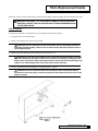
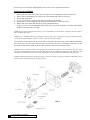
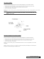
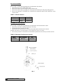
1
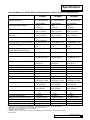
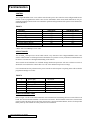
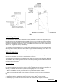
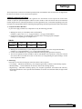
Cat. No. 01882311
Rev. D 09/17/02
DCO # 4625
Service
Manual
CULLIGAN
MEDALLIST SERIES™
AUTOMATIC
WATER CONDITIONER
MODELS FROM 2002
©2002 Culligan International Company
Printed in USA
Attention Culligan Customer:
The installation, service and maintenance of this equipment should
be rendered by a qualified and trained service technician. Your local
independently operated Culligan dealer employs trained service
and maintenance personnel who are experienced in the installation,
function and repair of Culligan equipment. This publication is written
specifically for these individuals and is intended for their use.
We encourage Culligan users to learn about Culligan products, but
we believe that product knowledge is best obtained by consulting
with your Culligan dealer. Untrained individuals who use this manual
assume the risk of any resulting property damage or personal
injury.
WARNING - Prior to servicing equipment,
disconnect power supply to prevent electrical
shock.
WARNING - If incorrectly installed, operated
or maintained, this product can cause severe
injury. Those who install, operate, or maintain
this product should be trained in its proper
use, warned of its dangers, and should read
the entire manual before attempting to install,
operate or maintain this product.
IF THIS E QUIPMENT IS TO BE USED IN THE
TREATMENT OF DRINKING WATER, THE WATER
MUST BE MICROBIOLOGICALLY SAFE.
Service
Manual
CULLIGAN
MEDALLIST SERIES™
AUTOMATIC
WATER CONDITIONER
MODELS FROM 2002
Table of Contents
Page
Introduction................................................................. 2
Specifications............................................................. 3
Familiarization............................................................ 4
Settings...................................................................... 7
Programming.............................................................11
Manual Cycling......................................................... 15
Service Check.......................................................... 16
Board Diagnostics.................................................... 17
Parts Replacement Guide........................................ 19
Troubleshooting Guide............................................. 23
Wire Diagram............................................................ 26
Flow Rate and Drain Line Charts............................. 27
Flow Charts.............................................................. 29
Parts List..............................................................34
Introduction
The Culligan Medallist Series™ Water Softeners are tested and validated by
WQA and certified by UL against ANSI/NSF Standard 44 for the effective reduction of calcium and magnesium along with Barium and Radium 226/228*.
Because the ability of the unit to remove Barium and Radium is based upon
reducing hardness to less than 1 gpg, effective hardness reduction should be
periodically verified. Hardness sample kits are available through your local Culligan Dealer.
ANSI/NSF 44
Water Softener
81WN
For installations in Massachusetts, Massachusetts Plumbing Code 248 CMR shall be adhered to. Consult
your licensed plumber for installation of this system.
SAFE PRACTICES
Throughout this manual there are paragraphs set off by special headings.
NOTICE: Notice is used to emphasize installation, operation or maintenance information which is important, but
does not present any hazard.
Example: NOTICE: The nipple must extend no more than 1 inch above the cover plate.
CAUTION: Caution is used when failure to follow directions could result in damage to equipment or
property. Example:
CAUTION: Disassembly while under water pressure can result in flooding.
WARNING: Warning is used to indicate a hazard which could cause injury or death if ignored. Example:
WARNING! ELECTRICAL SHOCK HAZARD! UNPLUG THE UNIT BEFORE
REMOVING THE COVER OR ACCESSING ANY INTERNAL CONTROL PARTS.
SERIAL NUMBERS
The control valve serial number is located on the back of the control.
The media tank serial number is located on the top surface of the tank.
NOTICE: Do not remove or destroy the serial number. It must be referenced on request for warranty repair or
replacement.
This publication is based on information available when approved for printing. Continuing design refinement
could cause changes that may not be included in this publication.
* Verified utilizing hardness surrogate per ANSI/NSF Standard 44.
2 CULLIGAN MEDALLIST SERIES
Specifications
CULLIGAN MEDALLIST SERIES WATER CONDITIONER WITH TIMECLOCK OR SOFT MINDER METER
8" MODEL
303 MODEL
Control Valve Type
5-cycle Reinforced
5-cycle Reinforced
Thermoplastic
Thermoplastic
Overall Conditioner Height
51 in
49 in
1,295 mm
1,245 mm
Media Tank Dimensions (Dia. x Ht.)
8 x 44 in
10 x 40 in
203 x 1,118 mm
254 x 1,016 mm
Salt Storage Tank Dimensions
16 x 43 in
18 x 43 in
(Dia. x Ht.)
457 x 1,092 mm
457 x 1,092 mm
18 x 43 in
457 x 1,092 mm
Exchange Media, Type and Quantity
Cullex® Media, 0.7 ft3 Cullex Media, 1.0ft3
Underbedding, Type and Quantity
Cullsan® Underbedding,
Cullsan Underbedding,
6 lb.
8 lb.
Exchange Capacity
18,300 gr @ 4 lb
20,200 gr @ 5.0 lb
1
@ Salt Dosage Per Recharge
25,100 gr @ 9.0 lb
29,400 gr @11 lb
27,500 gr @ 12 lb
35,000 gr @17 lb
Efficiency at Rated Sales Dosage5
4 lb. salt dosage:
5 lb. salt dosage
4570 gr./lb.
4050 gr./lb.
Freeboard to Media2
20.5 - 21.5 in
17 - 18 in
3
Freeboard to Underbedding
42.0 - 42.5 in
39.6 - 40.1 in
Salt Storage Capacity
250 lb or 375 lb
375 lb
Rated Service Flow @ Pressure Drop 5.9 gpm @ 12 psi
7.2 gpm @ 12 psi
Total Hardness, Maximum
75 gpg
99 gpg
Total Iron, Maximum (dissolved)
5 ppm
5 ppm
Hardness to Iron Ratio, Minimum
8 gpg to 1 ppm
8 gpg to 1 ppm
140 mg/L to 1 mg/L
140 mg/L to 1 mg/L
Operating Pressure
20 - 125 psi
20 - 125 psi
140 - 860 kPa
140 - 860 kPa
Operating Pressure (Canada)
20 - 90 psi
20 - 90 psi
140 - 620 kPa
140 - 620 kPa
Operating Temperature
33 - 120°F
33 - 120°F
1 - 50°C
1 - 50°C
Electrical Requirements
24V/60 Hz
24V/60 Hz
Electrical Power Consumption, Min./Max.
3 Watts/35 Watts
3 Watts/35 Watts
Drain Flow, Maximum4
1.1 gpm
2.0 gpm
Recharge Time, Average
85 min
64 min
Recharge Water Consumption
23.3 gal
61 gal
453 MODEL
5-cycle Reinforced
Thermoplastic
63 in
1,600 mm
10 x 54 in
254 x 1,372 mm
18 x 43 in
457 x 1,092 mm
Cullex Media, 1.5 ft3
Cullsan Underbedding,
8 lb.
24,900 gr @ 6 lb
39,200 gr @14 lb
43,500 gr @ 20 lb
6 lb. salt dosage
4150 gr./lb.
19.75 - 21.75 in
53.8 - 54.3 in
375 lb
7.0 gpm @ 13 psi 99 gpg
5 ppm
8 gpg to 1 ppm
140 mg/L to 1 mg/L
20 - 125 psi
140- 860 kPa
20 -90 psi
140 - 620 kPa
33 - 120°F
1 - 50°C
24V/60 Hz
3 Watts/35 Watts
2.1 gpm
64 min
65 gal
1 Capacities and corresponding salt dosages pertain to low hardness waters. Capacities given per recharge
2 Measured from top of media to top of inlet fitting (backwashed and drained)
3 Measured from top of underbedding to top of inlet fitting
4 Backwash at 120 psi (830 kPa)
5 Efficiency rating only valid at stated salt dosage on Soft-Minder® models and is efficiency rated according to ANSE/
NSF Standard 44.
SPECIFICATIONS 3
Familiarization
CONTROL
The Culligan Medallist Series™ water softener uses the same power valve control as in our Culligan® Mark 89/812
models. It can be programmed as either a time clock or Soft-Minder® meter model. Each model has its own programming parameters which can be set to control the operation and regeneration of the system. These functions are
outlined in Table 1.
TABLE 1
Function
Time of Day
Time of Regen.
Salt Dosage
Backwash Time
Brine Rinse Time
Gallons Capacity/Regen. Interval
Forced Regen. Interval
Lock/Unlock display
Time Clock
YES
YES
YES
YES
YES
YES
NO
YES
Soft-Minder Meter
YES
YES
YES
YES
YES
YES
YES*
YES
* When Time Clock Backup is set to "ON".
CIRCUIT BOARD
The AccuSoft™ microprocessor circuit board controls every function of the Culligan Medallist Series water
softener. This board has several unique features which allows it to perform a variety of functions. Familiarization of
the board is essential for a thorough understanding of the softener.
The AccuSoft circuit board has a set of default settings that the microprocessor will reset to whenever a meter is
attached or removed from the control. Table 2 is a list of the default microprocessor settings.
It is recommended to always disconnect the power from the circuit board prior to replacing meter cable so that the
programmed settings are not lost.
TABLE 2
1
2
4
5
6
8
10
Time of Day
Time of Regeneration
Salt Dosage
Backwash Time
Brine Rinse
Regeneration Interval
Display Lock Out
12:00 P.M.
2:00 A.M.
10 lbs.
10 min.
71 min.
3 days or 870 gallons
Disabled
AUXILIARY CONNECTIONS
Refer to Figure 1 for all circuit board connections. Power terminals are located along the lower section of the circuit
board. The connection marked 'MAIN' is for the main wire harness. The Soft-Minder connection is located in the
upper left side of the board. Next to the meter connection is a connection marked 'BATT', which is for the optional
battery back-up. All terminals are clearly marked to ease installation.
4 CULLIGAN MEDALLIST SERIES
FIG. 1
SOFT-MINDER® OPERATION
The Soft-Minder meter utilizes a turbine impeller to accurately monitor the customer's water usage. After a predetermined amount of water has passed through the system, the microprocessor will signal a regeneration. The "REG"
enunciator will light at this point. The unit will perform a standard regeneration cycle at the preset time, unless the
programming option "dip2" is changed from "DEL" to "Id". When programming option "dip2" is changed from
"DEL" to "Id", a regeneration will begin immediately.
The programming of the Soft-Minder provides several settable variables, the Time-of-Day, Time-of-Regeneration,
Salt Dosage, Backwash Time, Brine/Rinse Time, Gallons to Signal and Timeclock Backup, if active. Refer to the
programming section for further information on programming the microprocessor.
TIMECLOCK OPERATION
When the microprocessor is set-up as a time clock unit, the Culligan® Medallist control will regenerate at fixed
intervals. The regeneration interval can be set anywhere from 1 to 42 days.
The programming for the time clock models is limited to Time-of-Day, Time-of-Regeneration, Salt Dosage, Backwash
Time, Brine/Rinse Time, and the Regeneration Interval. Refer to the programming section for further information on
programming the microprocessor.
REGENERATION
There are several conditions that will cause the control to trip a regeneration. The "REG" enunciator will light when
the control has signaled for a regeneration. The "REG" enunciator will flash while the control is in regeneration. The
following are conditions that will call for regeneration, assuming "dip2" has been set to "DEL":
1. When the Soft-Minder meter has recorded the passage of a predetermined number or gallons
2. When the time clock has counted past the set number of days.
3. At the preset time, when the number of days without a regeneration is equal to the Timeclock Backup setting.
4. At the preset time, after the "REG" button is depressed once. "REG" will light.
5. Immediately, when the "REG" button is depressed for three seconds. "REG" will light and blink.
6. Immediately, if power to the unit has been off for more than 3 hours and time of day has been returned.
FAMILIARIZATION 5
If "dip2" is set to "Id", the unit will begin a regeneration immediately for instances 1 and 2. With "dip2" set to "del",
the regeneration will not begin until the preset regeneration time.
Note: If set to immediate mode as timeclock or timeclock backup, the unit will initiate regeneration at 12:00 AM.
In the delay mode, "REG" indicator will light at 12:00 AM and regeneration will occur at delayed time.
DISPLAY LOCKOUT
The Culligan Medallist Series™ control is equipped with a feature which will allow you to protect the programmed
settings from tampering by unauthorized individuals. When the lockout feature is activated, the only parameters
which can be adjusted are the Time-of-Day and the Time of Regeneration. Refer to the "Setting of the
Microprocessor" for activating this feature.
POWER LOSS
The AccuSoft® circuit board is equipped with a Hi-Cap Capacitor and EEPROM memory chip. The capacitor is
capable of maintaining the time, for at least two days (masked chip), in the event of a power outage. The EEPROM
ensures that the individual programming parameters of the softener are not lost.
If the power outage lasts long enough to drain the Hi-Cap Capacitor, the control will flash "12:00 PM" when power
is returned to the control. The unit will continue to keep time from the moment power is restored, and will initiate a full regeneration at the preset regeneration time. The time of day will need to be reset in order to return the
regeneration to its preset time.
FAILURE MODE
There are certain conditions that can be interpreted by the circuit board as a failure of the drive motor or motor
position switch. Upon failure detection the control will cease further operation. A telephone hand set symbol will be
shown in the upper left corner of the display and the error code will be shown. Listed below are the different error
codes.
1. Motor Always Turning
Error code "E1" occurs when the circuit board detects changes in the motor program switch when the motor is
not supposed to be turning. The phone icon and "E1" will be lit in the display.
2. Motor Never Turns
The Culligan Medallist Series control is equipped to detect no change in the motor position when the motor is
supposed to be turning (motor or piston locked in a frozen position). The AccuSoft circuit board will apply
power to the motor for 20 seconds. If there is no change in the motor homing or position switch, the control will
power down for 1 minute. The circuit board will repeat this procedure two more times in an attempt to remove the
obstruction. If no movement has been detected, the control will permanently power down and a phone icon and
an "E2" will appear in the display.
3. Homing Error
Error code "E3" occurs when the circuit board detects when the control is unexpectedly in the home position.
The phone icon and "E3" will be lit in the display.
Error Display Cancellation
The error code display can be removed by removing the power to the control for 1 minute. After clearing an error
condition, the control will default to the factory settings when power is restored.
6 CULLIGAN MEDALLIST SERIES
Settings
The mircoprocessor can be set in two distinct operation modes, Soft-Minder® meter or Timeclock. As shipped from
the factory, the control is set for 8" Timeclock operation.
CAPACITY AND SALT SETTINGS
As mentioned previously, the softener will regenerate once the amount of water equal to the treated water
volume set point has passed through the turbine for meter models or after a fixed time interval for timeclock
models. Regeneration is either delayed until the selected regeneration time or immediate depending on how the
microprocessor is programmed. Before completing the programming, the following information must be determined:
1. Compensated Water Hardness.
If your water supply contains iron, compensate for it by the following procedure:
1.
2.
Multiply the iron by 0.1 and add the result to the hardness.
Example: (3 ppm of iron x 0.1) + 25 gpg of hardness = 25.3 gpg of total hardness
Choose the % capacity you want and refer to the table below for the appropriate multiplier.
Example: 67% capacity gives a multiplier of 1.5.
TABLE 3
% Capacity
Multiplier
3.
4.
5.
50%
67%
75%
2
1.5
1.33
Multiply the result from Step 1 by the multiplier chosen in Step 2. This is the compensated hardness.
Example: 25.3 gpg total hardness x 1.5 = 38 gpg compensated hardness.
Use the effective hardness for sizing and to determine salt dosage and regeneration frequency.
The forced regeneration feature should be used for Soft-Minder meter operation to ensure the resin bed
does not become iron fouled due to lack of water flow. See "Programming the Option Settings" for the
forced regeneration feature.
2. Salt Dosage
From Table 4, select the salt dosage at which the softener will be operated.
•Low Setting — Maximum salt efficiency, more frequent regeneration, reduced overall softening capacity.
•Medium Setting — Good combination of efficiency and overall softening capacity.
•High Setting — Maximum softening capacity, less frequent regeneration, and reduced salt efficiency.
Recommended whenever iron is present and for hardness levels above 30 Grains Per Gallon, or high volume
water usage.
SETTINGS 7
TABLE 4 - SALT DOSAGE
Capacity160 lb. Brine Tank250 lb. Brine Tank375 lb. Brine Tank
"A" Dimension
"A" Dimension "A" Dimension
Salt
CapacitySecondary (Only)SecondaryPrimarySecondaryPrimary
Dosage 8" ft3 30 ft3 45 ft3
in.
(cm)
in. (cm) in. (cm) in. (cm) in. (cm)
4
18,300
X
X
7-3/4
19.7
6-5/8 16.8 4-5/8 11.7 5-1/2 14.0 3-1/2 8.9
5
20,000 20,000 20,000
9-1/2
24.1
8
20.3
6
15.2 6-1/2 16.5 4-1/2 11.4
6
22,000 22,500 23,500
11-1/4
28.6
9-3/8 23.8 7-3/8 18.7 7-1/2 19 5-1/2 14
7
23,200 24,400 26,500
13
33
10-7/8 27.6 8-7/8 22.5 8-1/2 21.6 6-1/2 16.5
8
24,100 25,700 29,000
14-3/4
37.5
12-1/4 31.1 10-1/4 26 9-1/2 24.1 7-1/2 19
9
25,100 27,000 31,300
16-1/2
42
13-5/8 34.6 11-5/8 29.5 10-1/2 26.7 8-1/2 21.6
10
26,100 28,300 33,300
18-1/4
46.3
15
38.1
13
33 11-1/2 29.2 9-1/2 24.1
11
26,800 29,400 35,000
20
51
16-3/8 41.6 14-3/8 36.5 12-1/2 31.7 10-1/2 26.7
12
27,500 30,500 36,500
21-3/4
55.2
17-3/4 45.1 15-3/4 40 13-1/2 34.3 11-1/2 29.2
13
X
31,500 38,400
21-1/2
59.7
19-1/8 48.6 17-1/8 43.5 14-1/2 36.8 12-1/2 31.7
14
X
32,500 39,200
25-1/4
64.1
20-1/2 52.1 18-1/2 47 15-1/2 39.4 13-1/2 34.3
15
X
33,300 40,400
—
—
21-7/8 55.5 19-7/8 50.5 16-1/2 42 14-1/2 36.8
16
X
34,100 41,200
—
—
23-1/4 59 21-1/4 54 17-1/2 44.5 15-1/2 39.4
17
X
35,000 41,800
—
—
24-5/8 62.5 22-5/8 57.5 18-1/2 47 16-1/2 42
18
X
X
42,400
—
—
26
66
24
61 19-1/2 49.5 17-1/2 44.5
19
X
X
42,900
—
—
27-3/8 69.5 25-3/8 64.5 20-1/2 52.1 18-1/2 47
20
X
X
43,500
—
—
28-3/4 73 26-3/4 68 21-1/2 54.6 19-1/2 49.5
3.
Treated Water Volume Set Point
Calculate the treated water volume set point using the following information:
•Softening capacity — Grains (based upon salt dosage setting).
•Compensated hardness of water supply — Grains Per Gallon
•Estimated daily water usage — Gallons Per Day (refer to Table 5)
TABLE 5 - Daily Water Usage
Persons in Household
2
3
4
5
6
7
8
9
10
Gallons Per Day
150
225
300
375
450
525
600
675
750
Example - Meter: Softener Model Medallist 2M
Capacity @ 9 lb. Salt Dosage: 25,100 Grains
Compensated Water Hardness: 19 Grains Per Gallon
Estimated Daily Water Usage: 300 Gallons Per Day
Softener Capacity
Treated Water Volume Set Point = Compensated Hardness
Softening Capacity
Divide by Compensated Hardness
Result is total number of gallons
of soft water per regeneration
Subtract daily Water Usage (needed
as a reserve to ensure continuous
soft water until regeneration occurs).
Round down to nearest ten for Treated
Water Volume Set Point
Set "CAPG" to 102
8 CULLIGAN MEDALLIST SERIES™
— Water Usage
25,100 Grains
÷ 19 Grains per Gallon
1,321 Gallons
— 300 Daily Water Usage (One Day Supply)
1,021 Gallons
1,020 Gallon Setting
Example - Timeclock: Softener Model Medallist 2
Capacity @ 9 lb. Salt Dosage: 25,100 Grains
Compensated Water Hardness: 19 Grains Per Gallon
Estimated Daily Water Usage: 300 Gallons Per Day
Softener Capacity
Treated Water Volume Set Point = Compensated Hardness
Softening Capacity
Divide by Compensated Hardness
Result is total number of gallons
of soft water per regeneration
Subtract daily Water Usage (needed
as a reserve to ensure continuous
soft water until regeneration occurs).
Divide by daily water usage
Round down to nearest day
Set "CAP" to 3
— Water Usage
25,100 Grains
÷ 19 Grains per Gallon
1,321 Gallons
— 300 Daily Water Usage (One Day Supply)
1,021 Gallons
÷ 300
3.4 Days
3.0 Days
Use the following worksheets to calculate and record the proper settings.
Treated Water Volume Set Point Work Sheet - Meter Models
1. Enter Softening Capacity
2. Divide by Compensation Hardness
÷
Result is Total Gallons of Soft Water Per Regeneration
=
3. Subtract Daily Water Usage (Reserve
—
Result
=
Round down to nearest ten for Treated Water Volume Set Point
Gallons
Treated Water Volume Set Point Work Sheet - Timeclock Models
1. Enter Softening Capacity
2. Divide by Compensation Hardness
÷
Result is Total Gallons of Soft Water Per Regeneration
=
3. Subtract Daily Water Usage (Reserve
—
4. Divide by Daily Water Usage
÷
Result
=
Round down to nearest ten for days between regeneration set point
Days
Note: All Softening capacity is based on new Cullex® resin and using sodium chloride as the regenerate: If potassium chloride is used reduce the rated softening capacity by 20%.
SETTINGS 9
BRINE VALVE "A" DIMENSION
The brine valve contains a float-actuated safety shut-off device to prevent overflow of the brine tank in the unlikely
case of an electrical or mechanical failure during the brine tank refill cycle.
It is recommended that the brine valve float be used as intended, that is, as a secondary, safety shut off. Remember,
the timer mechanism provides the primary refill shut-off. To use the float as a safety shut-off, refer to Table 4 for
the salt dosage and brine tank size being used. The "A" dimension is the distance between the filter screen and the
bottom of the float (Figure 2) when the float stem is in its fully raised position; adjust the float and rubber grommets
accordingly.
FIG. 2
10 CULLIGAN MEDALLIST SERIES™
Programming
Make sure the inlet water supply is turned off, then supply power to the timer. The display will power up flashing
"12:00 PM" and the motor will energize and cycle the control, without stopping, to the home position. This is
required to ensure that the control is in the home position.
The timer uses four buttons:
FIG. 3 - Circuit Board Display
1.
2.
3.
4.
STATUS:
PLUS SIGN "+":
MINUS SIGN "-":
REGEN.:
Advance timer through display options.
Increase the setting.
Decrease the setting.
Initiate a manual regeneration.
PROGRAMMING THE OPTION SETTINGS
The microprocessor has several programming options that can be changed for various additional functions. Listed
are the functions for the programming options used on the Culligan Medallist Series™ control.
Dip Switch
Function
Default Position
1
Service or Test
Service
2
Delay or Immediate Regeneration
Delayed Regeneration
3
Softener or Filter
Softener
4
Time Clock Backup
OFF
5
English or Metric
English
6
12 or 24 Hour Clock
12 Hour
7
3/4" or 1" Meter
3/4" Meter
1 Service or Test Mode
P r e s s a n d h o l d t h e “ S TAT U S ” k e y u n t i l “ d I P 1 ”
display. “dIP1” will blink for 3 seconds and then the display will
show the status of this option (SEr or tES). Toggle the feature
with the “+” or “-” key.
Note: Pressing “STATUS” after changing option to test mode
will place the control in test mode. After testing is complete
press and hold “STATUS” for 3 seconds to return to “dIP1”
setting. Placing the unit in test mode will not change any of the
programmed values.
2
Delay or Immediate Regeneration
Press the “STATUS” key. The display will blink “dIP2” for 3
seconds and then show the current status. Toggle between
“DEL” (Delay) and “Id” (Immediate) with the “+” or “-” key.
Note: Changing this setting will not change any of the
programmed value with the exception that Step #2, time of
regeneration will be ignored when set to immediate.
3
Softener or Filter
Press the “STATUS” key. The display will blink “dIP3” for 3
seconds and then show the current status. Toggle between
“SOF” (Softener) and “FIL” (Filter) with the “+” or “-” key.
Note: Changing this setting will cause the unit to load the
Filter or Softener defaults.
4
Timeclock Backup
Press the “STATUS” key. The display will blink “dIP4” for 3
appears
in
the
del
sof
PROGRAMMING 11
OFF
seconds and then show the current status. Toggle between
“OFF” (Timeclock backup is off) and “ON” (Timeclock
backup
is on) with the “+” or “-” key.
Note: Changing this setting will not change any of the
programmed values and will load the default Timeclock
Backup value of 3 days. Programming step 7 will be activated
when this is set to On.
Note: This option will only be available when the flowmeter is
plugged into the control
5
English or Metric
Press the “STATUS” key. The display will blink “dIP5” for 3
seconds and then show the current status. Toggle between
“En” (English units) and “MET” (Metric units) with the “+” or
“-” key.
6.
12 or 24 Hour Clock
Press the “STATUS” key. The display will blink “dIP6” for 3
seconds and then show the current status. Toggle between
“12 Hr” (12 hour clock) and “24 Hr” (24 hour clock) with the “+”
or “-” key.
7.
3/4" or 1" Meter
Press the “STATUS” key. The display will blink “dIP7” for 3
seconds.
Do not change setting from “3-4”
Note: The 3/4" meter setting is to be used with the Medallist
Series softener. The 1" meter setting is for future models.
3-4
setting the microprocessor
The microprocessor senses when it is installed as a Soft-Minder® control. Adding or removing any connection to
the board will automatically reset the microprocessor to the factory settings.
Step 1 – Programming Time of Day
Press the “STATUS” key.
The display will blink “tod” for 3 seconds and then change to time
of day with the “minutes” digits blinking.
Adjust the “minutes” digits with the “+” or “-” keys.
Press the “REGEN” key to blink the “hours” digits.
Adjust the “hours” digits with the “+” or “-” keys.
Press the “REGEN” key to cycle back to “minutes”
Note: The “hours” setting scrolls through 1-12 AM and 1-12 PM.
Make sure the proper AM or PM indicator is shown when setting
the time.
Step 2 – Programming Regeneration Time
Press the “Status” key after setting the time of day.
The display will blink “tor” for 3 seconds and then change to the
time setting with the “ones” digit blinking.
Adjust regeneration time as time of day above.
Note: This option will not show if the “dIP 2” option is set to immediate.
12 CULLIGAN MEDALLIST SERIES™
PM
AM
12:00
2:00
Step 3 – Programming Salt Dosage
Press the “Status” key after programming regeneration time.
The display will blink “SLtP” if set to English or “SLtG” if set to
Metric for 3 seconds and then display the salt dosage.
Adjust the setting with the “+” or “-” key (3-24 lbs.)(1-10 kgs.)
Note: This option will not show if the control is set to Filter mode.
10
Step 4 – Programming Backwash Time
Press the “Status” key after programming salt dosage.
The display will blink “bw” for 3 seconds and then display the backwash time in minutes.
Adjust the setting with “+” or “-” key. (1-40 minutes)
10
Step 5 – Programming Brine Draw/Slow Rinse Time
Press the “Status” key after programming the backwash time.
The display will blink “br” for 3 seconds and then display the brine
draw/slow rinse time in minutes.
Adjust the setting with the “+” or “-” key. (35-99 minutes). See Table
5 for suggested brine draw/slow rinse times.
Note: This option will not show if the control is set to Filter mode.
71
Step 6 – Programming Gallons (Liters) or Days to Regeneration
Meter Mode —
Press the “Status” key after programming the brine draw/slow rinse
time.
The display will blink “CAPG” (“CAPL”) for 3 seconds and then
display the gallons or liters set point.
Adjust the setting with the “+” or “-” key. (10-9990 Gallons)
(40-37000 Liters)
Note: The programmed value must be multiplied by 10 to obtain the
actual setting. For example, if 87 is shown in the display, the control
will regenerate after 870 gallons have passed through the meter.
OR
87
Timeclock Mode —
Press the “Status” key after programming the brine draw/slow rinse
time.
The display will blink “CAP” for 3 seconds and then display the
number of days between regenerations.
Adjust the setting with the “+” or “-” key. (1-42 days)
Step 7 – Programming Time Clock Backup
Press the “Status” key after programming the capacity.
The display will blink “tCb” for 3 seconds and then display the
backup number of days between regenerations.
Adjust the setting with the “+” or “-” key. (1-42 days)
Note: This option will only show if a meter is plugged into the control
and the timeclock backup option is turned on.
28
PROGRAMMING 13
Exiting Program Mode
From Step 6 (or step 7 if it is active) press the “Status” key.
The display will go blank.
Press the “Status” key again to exit programming.
Note: The control will exit the programming mode if no key press activity takes place within one minute.
Locking the Programmed Menu
Press and hold the “+” key for 3 seconds while in the service mode.
The display will show the status of the lock feature. (“LoC” or “unL”)
Adjust with the “+” or “-“ key.
Press the “STATUS” key to return to the service mode.
Note: While the programmed menu is locked (“LoC”) all of the programming menu items will display, however only the time of day and
time of regeneration can be changed.
Note: If programming times out, values will not be saved. The “Status”
key must be pressed to save values.
TABLE 6 - Suggested Brine Draw/Slow Rinse Times
Salt Dosage
3
4
5
6
7
8
9
10
11
12
13
14
15
16
17
18
19
20
21
22
23
24
Brine Draw/Slow Rinse Time (Minutes)
8" Tank
10" Tank
53
55
57
59
62
65
68
71
74
76
78
80
82
—
—
—
—
—
—
—
—
—
—
—
40
42
44
46
48
50
52
53
55
56
58
59
61
62
64
65
67
68
70
71
Note: Values are for 50 psi pressure. Minutes should be adjusted for lower and higher pressures to
ensure that the brine is fully rinsed out.
14 CULLIGAN MEDALLIST SERIES™
Manual Cycling
The Culligan® microprocessor can be indexed through the various regeneration stages. For all steps, the cycle
numbers do not appear, or change, until the motor stops.
1. Press the status button to move past the programming steps
until the display is blank. From blank display press the “+”
key. An "H" will appear in the display. The control is in the
HOME position.
REG
2. Press and hold the regen button. The 'REGEN' icon will blink,
and the motor will advance the control. A '1' will appear. The
unit is now in the BACKWASH position. The numbers to the
right indicates the time remaining for the cycle.
REG
3. Press the “+” key. A '2' will appear in the display, along
with the cycle time remaining. The control is in the BRINE
DRAW/SLOW RINSE cycle.
4. Press “+” key. A '3' will appear in the display, along with the
cycle time remaining. The control is now in the FAST RINSE/
BRINE REFILL cycle.
H 00
I I0
2 7I
3 08
H 00
7:28
REG
REG
5. Press the “+” key. An 'H' will appear in the display. The unit
is in the HOME position. The 'REGEN' enunciator is no longer blinking.
6. Press the status key. Time-of-Day appears in the display.
Note: If the “+” key is pressed to cycle the value from position “3”
to “Home”, the # regen counters will not be updated.
PM
MANUAL CYCLING 15
Service Check
The service mode allows one to view the instantaneous flow rate, the gallons remaining before the softener
signals for regeneration, the number of regenerations in the past 14 days, the total number of regenerations the
control has cycled through and the number of days since the last regeneration.
To enter the service check mode, follow these steps:
1. From the Blank display:
2. Press “-” key. The display will blink “FLO” for 3 seconds
and then display the gallons per minute flow rate. This
screen will update the current meter reading every 6 seconds.
Note: This display is only active if the flowmeter is connected to the valve.
3. Press “-” key. The display will blink “GAL” for 3
seconds and then displays the gallons remaining before
the unit signals for regeneration (multiply the displayed
number by 10).
Note: This display is only active if the flowmeter is connected to the valve.
4. Press the “-” key. The display will blink “14dY” for 3
seconds and then display the number of regenerations that
have occurred in the last 14 days.
5. Press the “-” key. The display will blink “totL” for 3
seconds and then display the total number of
regenerations this control has cycled through.
6. Press the “-” key. The display will blink “daYS” for 3
seconds and then display the number of days since last
regeneration.
Note: Pressing the “+” key at any time brings back to manual
cycling. Pressing “Status” will Exit the programming menu.
16 CULLIGAN MEDALLIST SERIES™
6.4
87
2
93
5
Board Diagnostics
To enter the circuit board test mode, follow the procedure listed below:
Service or Test Mode
Press and hold the “STATUS” key until “dIP 1” appears in the
display. “dIP 1” will blink for 3 seconds and then the display will
show the status of this option (SEr or tES). Toggle the feature with
the “+” or “-” key.
Note: Pressing “STATUS” after changing option to test mode
will place the control in test mode. After testing is complete press
and hold “STATUS” for 3 seconds to exit. Placing the unit in test
mode will not change any of the programmed values. (Refer to the
Service Manual for test menu).
1. Press the status key. The software version will be displayed.
E5 3.9
2. Press the status key. “tESt” will flash for 3 seconds, then all
segments of the display will be lit.
Note: If STATUS is pressed when “tESt” is flashing, it will
proceed to the next step.
- I88
- I88
- 2HP
3. Press the status key. If a flow meter is plugged into the circuit
board, a bar on the second digit of the display will be lit. The
display will be blank if a flow meter is not plugged into the
circuit board.
4. Press the status key. A “1” will appear on the display for 3
seconds.
5. Press the “+” key. A “2” will appear on the display for 3 seconds and the motor will run. An “H” in the display means the
motor homing switch is activated. A “P” on the display means
the motor program switch is activated. Press the “+” key again
and the motor will stop.
Note: If the “+” key is not pressed again, the motor will stop
turning after 30 seconds.
BOARD DIAGNOSTICS 17
6. Press the “-” key. A “3” will appear on the display for 3 seconds.
7. Press the “REG” key. A “4” will appear on the display for 3
seconds.
8. A signal from the flow meter will cause the phone icon to
flash. If a flow meter is connected to the circuit board, the bar
will be displayed in steps 3-7.
9. Hold the status key for 3 seconds to return to the time of day.
The motor will automatically energize to the home position.
Note: The control will not “TIME OUT” when in the test
mode.
18 CULLIGAN MEDALLIST SERIES™
- 388
- 488
Parts Replacement Guide
Familiarize yourself with the replacement procedures and component parts thoroughly before attempting any repair.
WARNING: DISCONNECT ALL ELECTRICAL POWER TO THE UNIT BEFORE
SERVICING. BYPASS THE UNIT AND RELIEVE SYSTEM PRESSURE BEFORE
ATTEMPTING REPAIR.
CIRCUIT BOARD
To replace the AccuSoft™ circuit board, refer to the parts list and proceed as follows:
1. Lift up the front cover of the control.
2. Remove all connected wire leads from the board.
CAUTION: Grip all connections to the circuit board by the connecting terminals for
assembly and disassembly. Failure to do so could result in damage to the wire leads or
connecting terminals.
3. Remove the circuit board from the retaining clips on the front cover.
CAUTION: Do not touch any surfaces of the circuit board. Electrical static discharges
may cause damage to the board. Handle the AccuSoft circuit board by holding only the
edges of the circuit board. Keep replacement boards in their special anti-static bags until
ready for use. Mishandling of the circuit board will void the warranty.
4. The new circuit board can be installed by reversing the steps 1-3 above.
CAUTION: The wire connectors must be connected to the circuit board properly.
The wires must exit the plug-in connector opposite of the raised white base of the circuit
board connector.
FIG. 4
PARTS REPLACEMENT GUIDE 19
Refer to Figure 5 for assembly and disassembly of the various valve components listed below.
DRIVE MOTOR ASSEMBLY
1.
2.
3.
4.
5.
6.
7.
Remove the drive motor cam switches by removing the one screw holding the switches to the motor.
Remove the E-ring holding the drive motor cam to the camshaft with a flat tip screwdriver.
Lift the cam off the shaft.
Using a 1/4" hex driver, remove the bolt above the eductor piston assembly.
Loosen the two screws holding the yoke support plate and the motor to the control valve.
Remove the yoke support plate and yoke by gently pulling them down.
Fully remove the two screws holding the motor to the control. The motor will pull away from the control and the
backplate will hang on the valve body.
NOTICE: If the unit is equipped with a meter, it is recommended to unclip the meter cable from the meter body to
allow backplate movement.
NOTICE: Care should be taken to not damage the brine piston if it is not going to be replaced. The brine piston
will need to be twisted slightly in order to remove it from the motor die casting.
This procedure can be followed in the reverse order to reassemble the motor to the control. When reassembling
the scotch yoke, the yoke must slide into the yoke support plate prior to pushing the assembly up into
the piston end and follower. Figure 6 shows proper assembly of the yoke into the support plate.
NOTICE: The seal pack may need to be repositioned in order for the follower to be inserted into the yoke, using
the motor and backplate to push the seal pack fully into the valve is helpful in aligning the yoke. Make sure that
the follower is in the follower slot on the yoke, and that the end of the piston rod is held in the end of the yoke.
NOTICE: When attaching the yoke support plate be certain to push up on the plate until the two mounting screws
bottom in the U-shaped channels of the support plate.
FIG. 5
20 CULLIGAN MEDALLIST SERIES™
SEAL PACK ASSEMBLY
Follow the instructions for replacing the drive motor assembly through step 7, then continue as follows:
1. With the drive motor and backplate set aside, firmly pull the seal pack assembly from the valve body.
2. Lightly lubricate the o-rings of the replacement seal pack with silicone grease.
3. Reverse the procedure for reassembly.
NOTICE: Use only silicone grease; petroleum-based lubricants will cause the degradation of the rubber
components.
CAUTION: Do not twist the seal pack upon insertion. This can cause the outer o-rings
to pinch, cut, or crimp.
FIG. 6
EDUCTOR PISTON/EDUCTOR SLEEVE ASSEMBLY
Follow the instructions for replacing the drive motor assembly through step 7, then proceed as follows:
1. With the drive motor set aside, firmly pull the eductor piston & sleeve assembly from the valve body.
2. Lightly lubricate the o-rings of the replacement piston & sleeve assembly with silicone grease.
3. Reverse the procedure for reassembly.
NOTICE: Use only silicone grease; petroleum-based lubricants will cause the degradation of the rubber
components.
NOTICE: The eductor piston & sleeve assemblies are unique to the softener, filter, and Super S™ controls. Refer to
the parts list to ensure that the proper assembly is used.
PARTS REPLACEMENT GUIDE
21
EDUCTOR ASSEMBLY
Refer to Figure 7 and the following instructions for replacement of the eductor.
1. Remove the three screws and the eductor plate.
2. Remove the eductor screen by lifting it from the eductor body.
3. Remove the eductor body by grasping one of the projections with the pliers and gently pulling upward.
4. Reverse the procedure to reassemble. Be certain that the replacement eductor body contains the correct
eductor nozzle.
TABLE 7 - Eductor Selection
Model
Nozzle Color Nozzle P/N
8" Medallist
Blue
00446038
30 & 45 Medallist Beige
00446039
BACKWASH FLOW CONTROL
Refer to Figure 7 and the following instructions for replacement of the backwash flow control:
1. Remove the drain elbow retaining clip from the valve body.
2. Pull the drain elbow from the valve body.
3. Remove the flow control from the valve body control and replace with a new flow restrictor.
NOTICE: The number on the backwash flow control should face into the valve body.
4. Reverse the procedure to reassemble. Be certain that the replacement is the correctly sized flow restrictor.
TABLE 8 - Backwash Flow Restrictor Selection
Model
Color & Number
8" Medallist
Black, #1
30 & 45 Medallist
Brown, #2
P/N
00331634
00331635
FIG. 7
22 CULLIGAN MEDALLIST SERIES™
Troubleshooting Guide
PROBLEM
CAUSE
SOLUTION
1. Unit has blank
A. Unit has no power
A. Verify that unit is connected to a
display. constant power source. (Not an outlet
on a switch)
B. Defective plug-in transformer
B. Replace plug-in transformer
2. Softener fails to
A. Electrical service to the unit has been
A. Verify that unit is connected to a
automatically initiate disrupted. constant power source. (Not an outlet
a regeneration. on a switch)
B. Soft-Minder® meter not properly B. Verify that meter cable is plugged into
recording total gallons used. circuit board.
The flow meter connection and Verify that meter cable is snapped into
operation can be verified using the test flow meter housing.
mode setting on the circuit board.
C.Incorrect programming
C.Refer to the 'Programming' section and
verify all settings.
3. Regeneration occurs A. Timer setting incorrect
A. Reset timer
at incorrect time.
B. Timer flashing
B. Reset timer and verify that unit is
connected to a constant power source.
C.Circuit board set to immediate
C.Set circuit board to delayed
regneration.
regeneration. Refer to 'Programming the option
settings'.
D.Incorrect programming
D.Refer to the 'Programming' section and
verify all settings.
4. Phone Icon is
A. Jammed seal pack or brine piston
A. Replace the seal pack or brine piston
as
displayed. outlined in the 'Parts Replacement
Guide' section.
B. Defective cam microswitches
B. Replace cam microswitches
C.Defective motor
C.Replace the motor as outlined in the
'Parts Replacement Guide' section.
5. Hard water to service A. Cul-Flo-Valv® is open or o-rings on
A. Close bypass valve or replace o-rings
Cul-Flo-Valv bypass stem are cut. on bypass stem.
The root cause of
B. Salt or Chemical storage tank is
B. Add salt or chemical to storage tank
hard water to service empty. and verify that proper level of salt or
may also lead to chemical is maintained.
problems such as
C.Eductor screen or nozzle plugged
C.Clean or replace eductor nozzle and/or
Iron or Hardness screen.
bleed in softeners.
D.Incorrect programming. (Salt dosage too D.Refer to 'Programming' section and
low for influent hardness) verify that settings are correct.
E. Insufficient water flowing to salt storage E. Verify that refill settings are correct, and
tank. clean the refill flow restrictor.
F. Internal seal leak
F. Replace seal pack as outlined in the
'Parts Replacement Guide' section.
G.Excessive water usage
G.Verify that programming is correct.
For Time Clock units increase
regeneration frequency.
H.Unconditioned water in water heater
H.Flush water heater to fill tank with
tank. conditioned water. Note: Follow water
heater manufacturer's recommendation.
TROUBLESHOOTING GUIDE
23
PROBLEM
CAUSE
SOLUTION
I. Salt bridge
I. Break up salt bridge in brine tank.
Do not try to break the salt bridge by
pounding on the outside of the brine tank
6. Loss of water pressureA. Inadequate mineral in media tank.
A. See problem 7 & 8.
B. Control and/or resin bed plugged with
B. Clean control and increase frequency of
debris or iron build-up. regenerations or length of backwash.
Plant recondition if necessary.
C.Inlet manifold plugged.
C.Remove control from tank and clean
inlet manifold. Check if eductor screen/
nozzle is also plugged.
D.Control plugged with foreign material
D.Clean control.
broken loose from recent plumbing work.
7. Loss of mineral to
A. Improper drain line flow control
A. Ensure that the control has the proper
drain drain line flow control. (See Table 8)
B. Air in water system
B. Ensure that system has proper air
eliminator control.
8. Mineral to service
A. Control connected to tank backwards
A. Verify that control is properly mounted
to the tank. (White coupling on the right
(inlet), black coupling on the left (outlet).
B. Defective outlet manifold
B. Replace outlet manifold
9. Water in storage
A. Secondary shut-off (brine valve float)
A. Refer to '"A" Dimension Charts/Refill
not properly set. Rates' to set the brine valve float
dimension.
B. Plugged drain line flow control. (Unit will B. Clean drain line flow control.
not draw brine)
C.Plugged eductor system. (Unit will not C.Clean eductor screen and nozzle.
draw brine)
D.Slow leak to brine line. Faulty eductor
D.Replace eductor sleeve and piston.
sleeve or piston.
E. Power outage while control was in E. Verify that items A-D are not the cause
refill position. the extra water in the storage tank.
10. Excessive water in
A. Faulty brine valve; float shut-off failure. A. Clean brine valve, replace stem seat, or
salt storage tank. replace brine valve.
(Water above brine
When the brine valve is faulty, one of the
valve float) items listed under problem 9 is also
required in order to produce excessive
water in the storage tank.
11.Unit fails to refill
A. Refill restrictor plugged
A. Clean or replace refill restrictor
storage tank.
B. Air in brine line causes float to slam
B. Verify that all tubing connections are
shut. (Float rod is rigid) properly assembled.
12. Unit fails to draw
A. Drain line flow control is plugged.
A. Clean drain line flow control
brine or chemical.
B. Plugged eductor system
B. Clean or replace eductor screen and
nozzle.
C.Line pressure too low
C.Increase line pressure to a minimum of
20 psi (140 kPa)
D.Internal control leak
D.Replace seal pack and/or eductor
sleeve/piston assembly.
E. Drain line too long or restricted
E. Verify proper drain line length. See 'Flow
Rate and Drain Line Charts'.
F. Eductor is drawing air into system.
F. Verify that all tubing connections are
properly assembled.
24 CULLIGAN MEDALLIST SERIES™
PROBLEM
CAUSE
SOLUTION
13. Unit uses an
A. Incorrect programming
A. Refer to the 'Programming' section and
excessive amount of verify all settings.
salt or chemical
B. Excessive water in storage tank
B. Refer to problems 9 & 10.
14. Continuous flow to
A. Internal seal pack leak.
A. Replace seal pack as outlined in the
drain. 'Parts Replacement Guide' section.
B. Seal pack or brine piston jammed
B. Replace the seal pack or brine piston
in position. as outlined in the 'Parts Replacement
Guide' section.
C.Power failure while unit was in
C.Restore power to unit. Verify that unit is
regeneration. connected to a constant power source.
15. Salt water to service A. Inadequate Brine/Rinse setting for
A. Refer to the 'Programming' section and
desired salt dosage. verify all settings.
B. Low water pressure lengthens brine
B. Increase line pressure to a minimum of
draw time. 20 psi (140 kPa).
C.Too much brine in the storage tank
C.Refer to problems 9 & 10.
TROUBLESHOOTING GUIDE
25
Wiring Diagram
Old Schematic
Models Purchased Before 3/1/2002
Current Schematic
Models Purchased After 3/1/2002
26 CULLIGAN MEDALLIST SERIES™
Extra
Brine
Line
0.9
1.2
1.9
2.1
2.1
2.2
SALT STORAGE ELEVATION
For each foot the salt storage tank is lowered below the floor on which the softener stands, it is necessary to deduct 8 feet of drain line from the allowable length shown on the chart. For each foot the salt storage tank is elevated above the floor on which the softener stands, the height of drain
discharge can be raised 2 inches, or the total length of the drain line can be increased 4 feet. In either case, deduction must also be made for extra
feet of brine line length in excess of the standard 4 feet. For this deduction, use column entitled, “EXTRA BRINE LINE”.
Fast
HEIGHT OF DRAIN DISCHARGE ABOVE FLOOR
Back Rinse Fast Rinse
Min. Back Wash B/W Rinse Rate Rinse Rate
Pres-
Vac. Wash Sec./ Restric- Rate Sec./ Rate Sec./
sure
Ht. gpm Gal. tor No. gpm Gal. gpm Gal. Eductor psi 4 in. 1 ft. 2 ft. 3 ft. 4 ft. 5 ft. 6 ft. 7 ft. 8 ft. 9 ft. 10 ft.
0.22 273
20
Min. Max.
25
33
27
17
7
30
56
50
40
30
20
10
35
74
68
58
48
38
28
18
8
40
88
82
72
62
52
42
32
22
12
45 100 94
84
74
64
54
44
34
24
14
50 112 106 96
86
76
66
56
46
36
26
16
55 121 115 105 95
85
75
65
55
45
35
25
60 130 124 114 104 94
84
74
64
54
44
34
65 137 131 121 111 101 91
81
71
61
51
41
19" 2.0 30
2 0.32 188 2.0 30 Blue 70 143 137 127 117 107 97
87
77
67
57
47
Avg. Avg.
75 147 141 131 121 111 101 91
81
71
61
51
80 149 143 133 123 113 103 93
83
73
63
53
85 151 145 135 125 115 105 95
85
75
65
55
90 153 147 137 127 117 107 97
87
77
67
57
95 156 150 140 130 120 110 100 90
80
70
60
100 159 153 143 133 123 113 103 93
83
73
63
105
110
0.42 142
115
Max. Min.
120
CULLIGAN MEDALLIST SERIES™, 8” WATER CONDITIONER
EXTRA BRINE LINE
This column in the number of feet deducted from the allowable drain line length
for each foot the brine line is extended beyond the standard 4-foot length.
Flow Rate and Drain Line Charts
FLOW RATE AND DRAIN LINE CHARTS
27
28 CULLIGAN MEDALLIST SERIES
Fast
HEIGHT OF DRAIN DISCHARGE ABOVE FLOOR
Back Rinse Fast Rinse
Min. Back Wash B/W Rinse Rate Rinse Rate
Pres-
sure
Vac. Wash Sec./ Restric- Rate Sec./ Rate Sec./
Ht. gpm Gal. tor No. gpm Gal. gpm Gal. Eductor psi 4 in. 1 ft. 2 ft. 3 ft. 4 ft. 5 ft. 6 ft. 7 ft. 8 ft. 9 ft. 10 ft.
0.42 142
20
5
Min. Max.
25
18
12
30
44
38
28
18
35
62
56
46
36
26
16
6
40
78
72
62
52
42
32
22
12
45
93
87
77
67
57
47
37
27
17
7
50 103 97
87
77
67
57
47
37
27
17
7
55 110 104 94
84
74
64
54
44
34
24
14
60 117 111 101 91
81
71
61
51
41
31
21
65 122 116 106 96
86
76
66
56
46
36
26
19" 3.5 17
3 0.75 80 3.5 17 Beige 70 129 123 113 103 93
83
73
63
53
43
33
Avg. Avg.
75 133 127 117 107 97
87
77
67
57
47
37
80 138 132 122 112 102 92
82
72
62
52
42
85 142 136 126 116 106 96
86
76
66
56
46
90 145 139 129 119 109 99
89
79
69
59
49
95 147 141 131 121 111 101 91
81
71
61
51
100 149 143 133 123 113 103 93
83
73
63
53
105 151 145 135 125 115 105 95
85
75
65
55
110 153 147 137 127 117 107 97
87
77
67
57
1.08 55
115
Max. Min.
120
CULLIGAN MEDALLIST SERIES™, 10” WATER CONDITIONER
Extra
Brine
Line
0.9
1.0
1.1
1.2
1.4
1.6
1.8
2.0
2.0
2.1
2.2
2.3
2.4
2.5
2.7
2.9
3.0
3.0
3.1
Flow Charts
FLOW CHARTS
29
30 CULLIGAN MEDALLIST SERIES™
FLOW CHARTS
31
32 CULLIGAN MEDALLIST SERIES™
FLOW CHARTS
33
Control Valve Parts List
34 CULLIGAN MEDALLIST SERIES™
CONDITIONER TANK PARTS LIST
35
01014042
00449865
01013083
01013606
P0447986
P0308407
P0448750
P0447987
P0443291
P0303192
P0-3031-93
00446835
P0331634
P0331635
P0447387
P0308438
P0308437
00401248
00446038
00446039
P0445269
00445797
00401022
P0448687
01005130
00448128
P0444914
00448126
01004689
P0318383
01014036
01882288
P0448686
—
1
‡ 2
‡ 3
‡ *
‡ *
‡ *
‡ *
4
5
6
7
8
9
‡ 10
‡ 11
‡ 12
‡ 13
14
‡ 15
16
17
18
19
‡ 20
21
22
23
24
25
26
Control Valve Assembly - Medallist
Control Valve
Seal Pack Assembly
Eductor Sleeve and Eductor Piston Assembly
O-Ring, Eductor Sleeve, Small O-Ring (25/Kit)
O-Ring, Eductor Sleeve, Large O-Ring (25/Kit)
Screen, Eductor Sleeve (10/Kit)
O-Ring, Eductor Piston (10/Kit)
Connector Brine Line (25/Kit)
Insert, PP, 0.312" (25/Kit)
Nut, PP, 0.312" (25/Kit)
Drain Elbow Assembly w/O-Ring
Backwash Restrictor, #1, 8" Tanks (10/Kit)
Backwash Restrictor, #2, 10" Tanks (10/Kit)
Retainer, Drain Elbow (25/Kit)
O-Ring, Eductor Nozzle and Throat (10/Kit)
O-Ring, Eductor Throat (25/Kit)
Eductor Throat w/O-Rings
Eductor Nozzle - Blue, 8" Tanks
Eductor Nozzle - Beige, 10" Tanks
Eductor Screen (10/Kit)
Gasket
Eductor Port Cover
Screw (25/Kit)
Bracket
Retainer, Rear Body Plug
O-Ring, Rear Seal (10/Kit)
Rear Body Plug
Cul-Flo Bracket
Screw (10/Kit)
Back Plate
Timer Label
Screw (25/Kit)
Description
‡ Recommended Spare Parts
* Not Illustrated
Part No.
Item
‡ 29
30
31
32
33
34
35
36
37
38
39
40
41
42
43
44
51
52
53
59
60
61
*
*
*
*
*
*
*
Item
01003244
00401040
P0318455
P1013043
01013031
P1001784
00443559
P0318452
01014179
00318354
00445221
00445246
01012649
01012648
01012647
01014037
01014083
01014734
01006498
P1000372
01014038
00441410
01014172
01012956
01012905
01014076
01014074
01014787
P0451701
01013839
Part No.
Switch
Switch Bracket
Screw (25/Kit)
Retaining E-Ring (10/Kit)
Cam
Screw (25/Kit)
Roll Pin
Screw (25/Kit)
Drive Motor & Bracket Assembly 24V/60Hz
Nut
Bellcrank
Roll Pin
Follower
Yoke
Bracket
Cover
Power Cord (Quick Disconnect)
Power Cord (Direct to Circuit Board)
Plug, Snap-In
Strain Relief (25/Kit)
Hinge, Circuit Board Plate
Screw
Circuit Board (25/Kit)
Wall Mount Transformer
Flow Meter Assembly
Wire Harness, Switches & Motor (Quick Disconnect)
Wire Harness, Circuit Board (Quick Disconnect)
Harness (Motor & Switches to Circuit Board)
Hose Clamp, Drain (25/Kit)
Back-up Battery
Description
Conditioner Tank Parts List
Item
1
‡2
3
‡4
5
*
Part No.
00440821
01014889
01014890
00441897
01014891
01014892
00443282
P0333957
00444808
00440052
01000819
01012828
01012829
P0308427
* Not Illustrated
36 CULLIGAN MEDALLIST SERIES™
Description
Tank Assembly, 8", Complete
Tank Assembly, 10" x 40", Complete
Tank Assembly, 10" x 54", Complete
Replacement Tank, 8", Empty
Replacement Tank, 10" x 40", Empty
Replacement Tank, 10" x 54", Empty
Coupling (less O-rings)
O-ring (4 required)
Adapter
O-ring
Outlet manifold, 8"
Outlet manifold, 10" x 40"
Outlet manifold, 10" x 54"
O-ring (outlet manifold)
Salt Storage Tank Parts List
Item
Part No.
—
—
—
—
—
† 1
2
—
—
—
—
3
—
—
00441390
00441886
01004875
00441887
01004876
01004870
00303993
01014942
00401042
00303980
01014943
00304010
00441391
00303975
Description
Brine System, 160 lb. Replacement
Brine System, 250 lb. Replacement
Brine System, 250 lb. Replacement Less Salt Plate
Brine System, 375 lb. Replacement
Brine System, 375 lb. Replacement Less Salt Plate
Gold Band
Cover with Band, 250 lb.
Cover 250 lb. Less Gold Band
Cover with Band, 160 lb.
Cover with Band, 375 lb.
Cover 375 lb. Less Gold Band
Tank Only, 250 lb.
Tank Only, 160 lb.
Tank Only, 375 lb.
† Order by footage required
SALT STORAGE TANK PARTS LIST
37
Brine Valve Parts List
Item
Part No.
— 00441888
—
00401141
1
00303193
2
00303192
3
00440796
‡4 00308407
‡5 00401622
6
00340014
7
00440795
‡8 00332528
9
00223435
10 00304703
11 00304718
12 00444873
13 00332072
14 00444664
‡15 00444496
16 00447392
17 00447781
‡18 00304804
19 00541821
00541834
20 01004901
00-4413-92
21 00-3046-06
* 00-4463-88
* 00-4463-89
Description
Brine Valve Assembly
Brine Valve Assy., Brine Tank, 160 lb.
Plastic Nut, 5/16-inch
Plastic Insert
Refill Cap
O-ring
Flow Restrictor, No. 5, 0.45 gpm (170 lpm)
Stem Seat Assy., 250 lb. (114 kg) & 375 lb.
(170 kg)
Refill Body
Hat Screen
Plastic Pipe, 1/4-inch NPT x 35 inches long,
250 lb. (114 kg) & 375 lb. (170 kg)
Float Retainer (2 required)
Float Weight, Stainless Steel (2)
Float
Screen Top Seal
Filter Screen Cap
Stem Seat
Insert
Air Eliminator Ball
Ball Seat
Float Valve Body with Ball Seat
Float Valve Body with Ball Seat, 150 lb.
Brine Tank
Brine Valve Chamber, 250 lb. (114 kg) &
375 lb. (170 kg) Salt Storage Tank
Brine Valve Chamber, 160 lb.
Cap, Brine Valve Chamber
Screw, St. Steel, Brine Valve Chamber
Nut, St. Steel, Brine Valve Chamber
* Not Illustrated
‡ Recommended Spare Parts
38 CULLIGAN MEDALLIST SERIES™
Materials & description: 8-1/2 x 11, 40 page book, saddle stitched, three hole
punched - Prints black ink on 20# white
LET
CHANGE
A
DCO 1610
B
DCO 2882
C
DCO 3594
D
DCO 4625
BY APRVD
DATE
TPD
JB
10/19/00
SMP MW
9/7/01
LR
JS
06/05/02
LR
JS
09/17/02
This page contains materials and DCO
information. IT DOES NOT PRINT AS
PART OF THE DOCUMENT!