1
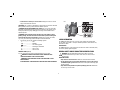
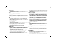
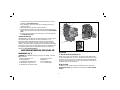
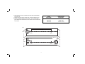
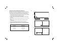
INSTRUCTION MANUAL
DW089-XE
3 BEAM LINE LASER
WARNING! Laser radiation exposure. Do not disassemble or modify the laser
level. There are no user serviceable parts inside. Serious eye injury could result.
WARNING: Hazardous radiation. Use of controls or adjustments or performance
of procedures other than those specified herein may result in hazardous radiation
exposure.
• Do not operate the laser in explosive atmospheres, such as in the presence of
flammable liquids, gases, or dust. Power tools create sparks which may ignite
the dust or fumes.
• Use the laser only with the specifically designated batteries. Use of any other
batteries may create a risk of fire.
• Store idle laser out of reach of children and other untrained persons. Lasers
are dangerous in the hands of untrained users.
• Use only accessories that are recommended by the manufacturer for your
model. Accessories that may be suitable for one laser, may create a risk of injury
when used on another laser.
• Tool service must be performed only by qualified repair personnel. Service
or maintenance performed by unqualified personnel may result in injury.
To locate your nearest DEWALT service center call 1800 444 224 (Aust) or
0800 339 258 (NZ).
• Do not use optical tools such as a telescope or transit to view the laser beam.
Serious eye injury could result.
• Do not place the laser in a position which may cause anyone to intentionally
or unintentionally stare into the laser beam. Serious eye injury could result.
• Do not position the laser near a reflective surface which may reflect the laser
beam toward anyone’s eyes. Serious eye injury could result.
• Turn the laser off when it is not in use. Leaving the laser on increases the risk
of staring into the laser beam.
• Do not modify the laser in any way. Modifying the tool may result in hazardous
laser radiation exposure.
• Do not operate the laser around children or allow children to operate the
laser. Serious eye injury may result.
• Do not remove or deface warning labels. If labels are removed user or others
may inadvertently expose themselves to radiation.
Definitions: Safety Guidelines
The definitions below describe the level of severity for each signal
word. Please read the manual and pay attention to these symbols.
DANGER: Indicates an imminently hazardous situation which, if
not avoided, will result in death or serious injury.
WARNING: Indicates a potentially hazardous situation which, if not
avoided, could result in death or serious injury.
CAUTION: Indicates a potentially hazardous situation which, if not
avoided, may result in minor or moderate injury.
NOTICE: indicates a practice not related to personal injury which, if
not avoided, may result in property damage.
IF YOU HAVE ANY QUESTIONS OR COMMENTS ABOUT THIS OR ANY DEWALT TOOL,
CALL US AT: 1800 444 224 (Aust) or 0800 339 258 (NZ).
SAFETY INSTRUCTIONS FOR POWER TOOLS
When using power tools, always observe the safety regulations applicable in your
country to reduce the risk of fire, electric shock and personal injury. Read the following
safety instructions before attempting to operate this product. Keep these instructions in
a safe place.
WARNING: To reduce the risk of injury, read the instruction manual.
SAFETY INSTRUCTIONS FOR LASERS
WARNING! Read all safety warnings and all instructions Failure to follow
the warnings and instructions may result in electric shock, fire and/or serious
injury.
SAVE THESE INSTRUCTIONS
1
• Position the laser securely on a level surface. Damage to the laser or serious
injury could result if the laser falls.
FIG. 1
CAUTION: Use of controls or adjustments or performance of procedures other than
those specified herein may result in hazardous radiation exposure.
WARNING! DO NOT DISASSEMBLE THE LASER. There are no user serviceable
parts inside. Disassembling the laser will void all warranties on the product. Do not
modify the product in any way. Modifying the tool may result in hazardous laser
radiation exposure.
WARNING: Avoid prolonged contact with dust from power sanding, sawing,
grinding, drilling, and other construction activities. Wear protective clothing and
wash exposed areas with soap and water. Allowing dust to get into your mouth,
eyes, or lay on the skin may promote absorption of harmful chemicals.
• The label on your tool may include the following symbols.
V ................................... volts
mW ............................... milliwatts
.................... laser warning symbol
nm ................................. wavelength in nanometers
II .................................... Class 2 Laser
IIIa ................................. Class 3a Laser
LASER INFORMATION
The DW089-XE 3 Beam Line Laser is a Class 2 laser product and complies with
21 CFR 1040.10 and 1040.11 except for deviations pursuant to laser notice No. 50,
dated June 24, 2007.
INTRODUCTION
The DW089-XE laser is a self-leveling laser tool that can be used for horizontal (level)
and vertical (plumb) alignment projects.
GENERAL SAFETY RULES FOR BATTERY OPERATED TOOLS
WARNING LABELS (FIG. 1)
For your convenience and safety, the following labels are on your laser.
WARNING: TO REDUCE THE RISK OF INJURY, USER MUST READ
INSTRUCTION MANUAL. USE AA SIZE BATTERIES.
WARNING! Read and understand all instructions. Failure to follow all
instructions listed below may result in electric shock, fire and/or serious
personal injury.
WORK AREA SAFETY
• Keep work area clean and well lit. Cluttered or dark areas invite accidents.
• Do not operate power tools in explosive atmospheres, such as in the presence
of flammable liquids, gases or dust. Power tools create sparks which may ignite
the dust or fumes.
• Keep children and bystanders away while operating a power tool. Distractions
can cause you to lose control.
WARNING: LASER RADIATION. DO NOT STARE INTO BEAM. CLASS 2
LASER PRODUCT.
AVOID EXPOSURE. LASER RADIATION IS EMITTED FROM THESE APERTURES.
2
• Dress properly. Do not wear loose clothing or jewelry. Keep your hair, clothing
and gloves away from moving parts. Loose clothes, jewelry or long hair can be
caught in moving parts.
POWER TOOL USE AND CARE
• Do not use the power tool if the switch does not turn it on and off. Any power
tool that cannot be controlled with the switch is dangerous and must be repaired.
• Store idle power tools out of the reach of children and do not allow persons
unfamiliar with the power tool or these instructions to operate the power tool.
Power tools are dangerous in the hands of untrained users.
• Maintain power tools. Check for misalignment or binding of moving parts,
breakage of parts and any other condition that may affect the power tool’s
operation. If damaged, have the power tool repaired before use. Many
accidents are caused by poorly maintained power tools.
• Use the power tool, accessories and tool bits, etc. in accordance with these
instructions, taking into account the working conditions and the work to be
performed. Use of the power tool for operations different from those intended
could result in a hazardous situation.
SERVICE
• Have your power tool serviced by a qualified repair person using only
identical replacement parts. This will ensure that the safety of the power tool is
maintained.
To locate your nearest DEWALT service center call 1800 444 224 (Aust) or 0800
339 258 (NZ).
ELECTRICAL SAFETY
• Use battery operated tool only with the specifically designed batteries. Use of
any other batteries may create a risk of fire.
Battery
This tool is powered by four 1.5V AA size batteries.
To install batteries:
1. Lift up the battery compartment cover (A) as shown in Figure 2.
2. Insert four fresh AA batteries in the compartment, placing the batteries according
to (+) and (–) on the inside of the battery door.
WARNING: Batteries can explode, or leak, and can cause injury or fire. To
reduce this risk:
• Carefully follow all instructions and warnings on the battery label and package.
• Always insert batteries correctly with regard to polarity (+ and –), marked on the
battery and the equipment.
• Do not short battery terminals.
• Do not charge batteries.
• Do not mix old and new batteries. Replace all of them at the same time with new
batteries of the same brand and type.
• Remove dead batteries immediately and dispose of per local codes.
• Do not dispose of batteries in fire.
• Keep batteries out of reach of children.
• Remove batteries if the device will not be used for several months.
PERSONAL SAFETY
• Stay alert, watch what you are doing and use common sense when operating
a power tool. Do not use a power tool while you are tired or under the
influence of drugs, alcohol or medication. A moment of inattention while
operating power tools may result in serious personal injury.
• Use personal protective equipment. Always wear eye protection. Protective
equipment such as dust mask, non-skid safety shoes, hard hat, or hearing
protection used for appropriate conditions will reduce personal injuries.
• Do not overreach. Keep proper footing and balance at all times. This enables
better control of the power tool in unexpected situations.
Electrical Safety
• Young children and the infirm. This appliance is not intended for use by
young children or infirm persons without supervision. Young children should be
supervised to ensure that they do not play with this appliance.
OPERATING TIPS
• Use only new, high-quality, name brand batteries for best results.
• Ensure batteries are in good working condition. If the low battery red indicator
light is flashing, the batteries need replacement.
• To extend battery life, turn laser off when not working with or marking the beam.
3
• To ensure the accuracy of your work, check often to make sure your laser is
calibrated. See Field Calibration Check.
• Before attempting to use the laser, make sure it is positioned securely, on a
smooth, flat surface.
• Always mark the center of the beam created by the laser.
• Extreme temperature changes may cause movement of internal parts that can
affect accuracy. Check your accuracy often while working. See Field Calibration
Check.
• If the laser has been dropped, check to make sure your laser is still calibrated.
See Field Calibration Check.
LOW BATTERY INDICATION
The DW089-XE laser is equipped with a red indicator light (B), as shown in Figure 2.
The red indicator light is located to the left of the on/off buttons (C, D, E).
A flashing red indicator light indicates that the batteries are low and need to be
replaced. The laser may continue to operate for a short time while the batteries
continue to drain, but the beam(s) will quickly dim. After fresh batteries are installed
and the laser is turned on again, the laser beam(s) will return to full brightness and
the red indicator light will stay off. (A flashing laser beam is not caused by low
batteries; see Out of Tilt Range Indicator.)
FIG. 2
G
F
H
B
D
(–)
A
(+)
C
E
(+)
(–)
A, I
A
I
SAVE THESE INSTRUCTIONS FOR FUTURE USE
OPERATION
COMPONENTS (Fig. 2)
To Turn the Laser On and Off (Fig. 2)
WARNING: Never modify the power tool or any part of it. Damage or personal
injury could result.
A. Battery compartment cover
F. Magnetic pivot bracket
B. Red indicator light
G. Keyhole slot
C. ON/OFF button: horizontal laser line
H. Fine adjustment knob
D. ON/OFF button: vertical laser line
I. 1/4" x 20 female thread
E. ON/OFF button: side vertical laser line
With the laser off, place it on a flat surface. This model has three ON/OFF buttons,
one for a horizontal laser line (C), one for a vertical laser line (D) and one for a side
vertical laser line (E). Each laser line is powered on by pressing its ON/OFF button.
The laser lines can be powered one at a time or at the same time. Pressing the ON/
OFF buttons again turns the laser lines off.
Using the Laser
The beams are level or plumb as long as the calibration has been checked (see
Field Calibration Check) and the laser beam is not flashing (see Out of Tilt Range
Indicator).
4
OUT OF TILT RANGE INDICATOR (FIG. 3)
The DW089-XE laser is designed to
self-level. If the laser has been tilted so
much that it cannot level itself (average
>4 ° tilt), it will flash the laser beam. The
flashing beam indicates the tilt range has
been exceeded and IS NOT LEVEL (OR
PLUMB) AND SHOULD NOT BE USED FOR
DETERMINING OR MARKING LEVEL (OR
PLUMB). Try repositioning the laser on a
more level surface.
SLOPING THE LASER
If the DW089-XE laser is tilted beyond 15 °
out of level, its laser beams will stay on
longer between flashes to make it easier
to do angled work.
USING THE PIVOT BRACKET (FIG. 2)
FIG. 4
FIG. 3
FIG. 5
J
H
F
K
L
>4°
ALIGNING THE VERTICAL BEAM – FINE ADJUST (FIG. 5)
The fine adjustment knob (H) on the top of the DW089-XE is for lining up the vertical
beams. Place the DW089-XE on a flat surface and turn the knob to the right to move
the beam to the right or to the left to move the beam to the left.
Rotating the fine adjustment knob adjusts the entire internal mechanism, maintaining
the 90 ° angle between the two vertical beams.
LEVELING THE LASER
As long as the DW089-XE laser is properly calibrated, the laser is self-leveling. Each
laser is calibrated at the factory to find level as long as it is positioned on a flat
surface within average ± 4 ° of level. No manual adjustments are required.
AVERAGE
WARNING: Position the laser and/or wall mount on a stable surface. Serious
personal injury or damage to the laser may result if the laser falls.
The DW089-XE laser has a magnetic pivot bracket (F) permanently attached to the
unit. This bracket allows the unit to be mounted to any upright surface made of steel
or iron. Common examples of suitable surfaces include steel framing studs, steel door
frames and structural steel beams. The bracket also has a keyhole slot (G) allowing
the unit to be hung from a nail or screw on any kind of surface.
USING THE LASER WITH THE WALL MOUNT (FIG. 4)
The laser wall mount (J) offers more mounting options for the DW089-XE laser. The
wall mount has a clamp (K) at one end which can be fixed to a wall angle for acoustic
ceiling installation. At each end of the wall mount is a screw hole (L), allowing the
wall mount to be attached to any surface with a nail or screw.
Once the wall mount is secured, its steel plate provides a surface to which the
magnetic pivot bracket (F) can be attached. The position of the laser can then be finetuned by sliding the magnetic pivot bracket up or down on the wall mount.
MAINTENANCE
• To maintain the accuracy of your work, check the laser often to make sure it is
properly calibrated. See Field Calibration Check.
• Calibration checks and other maintenance repairs may be performed by DEWALT
service centers.
• When not in use, store the laser in the kit box provided. Do not store your laser at
temperatures below -20 °C (-5 °F) or above 60 °C (140 °F).
• Do not store your laser in the kit box if the laser is wet. The laser should be dried
first with a soft dry cloth.
5
Cleaning
1. Attach the laser to a wall using its pivot bracket, with the laser facing straight
ahead toward the opposing wall (0 degree position).
2. Turn on the laser’s horizontal beam and mark the beam position on the opposing
wall directly across from the laser. Always mark the center of the beam’s
thickness.
3. Pivot the laser to the extreme left (-90 degree position) and mark the beam
position on the opposing wall.
4. Pivot the laser to the extreme right (+90 degree position) and mark the beam
position on the opposing wall.
5. Measure the vertical distance between the lowest mark (A) and the highest mark
(B). If the measurement is greater than the values shown below, the laser must
be serviced at an authorized service center.
Exterior plastic parts may be cleaned with a damp cloth. Although these parts are
solvent resistant, NEVER use solvents. Use a soft, dry cloth to remove moisture from
the tool before storage.
FIG. 6
STEP 5
B
A
STEP 3
STEP 4
Distance
Between Walls
STEP 2
STEP 3
-90˚
Allowable Distance
Between Marks
9.0 m (30')
3.0 mm (1/8")
12.0 m (40')
4.0 mm (5/32")
15.0 m (50')
5.0 mm (7/32")
CHECKING ACCURACY – HORIZONTAL BEAM, PITCH DIRECTION (FIG. 7)
Checking the horizontal pitch calibration of the laser requires a single wall at least 9 m
(30') long. It is important to conduct a calibration check using a distance no shorter
than the distance of the applications for which the tool will be used.
1. Attach the laser to one end of a wall using its pivot bracket.
2. Turn on the laser’s horizontal beam and pivot the laser toward the opposite end
of the wall and approximately parallel to the adjacent wall.
3. Mark the center of the beam at two locations (C, D) at least 30' (9m) apart.
4. Reposition the laser to the opposite end of the wall.
5. Turn on the laser’s horizontal beam and pivot the laser back toward the first end
of the wall and approximately parallel to the adjacent wall.
90˚
STEP 1
Field Calibration Check
CHECKING ACCURACY – HORIZONTAL BEAM, SCAN DIRECTION (FIG. 6)
Checking the horizontal scan calibration of the laser requires two walls 30' (9 m)
apart. It is important to conduct a calibration check using a distance no shorter than
the distance of the applications for which the tool will be used.
6
6. Adjust the height of the laser so that the center of the beam is aligned with the
nearest mark (D).
7. Mark the center of the beam (E) directly above or below the farthest mark (C).
8. Measure the distance between these two marks (C, E). If the measurement is
greater than the values shown below, the laser must be serviced at an authorized
service center.
Distance
Between Walls
Allowable Distance
Between Marks
9.0 m (30')
6.0 mm (1/4")
12.0 m (40')
8.0 mm (5/16")
15.0 m (50')
10.0 mm (13/32")
FIG. 7
9 m (30')
STEP 1, 2
C
STEP 3
D
STEP 3
STEPS 4, 5
C
STEP 8
E
STEP 7
D
STEP 6
7
5. Measure the distance between the two ceiling marks (G, H). If the measurement
is greater than the values shown below, the laser must be serviced at an
authorized service center.
CHECKING ACCURACY – VERTICAL BEAMS (FIG. 8)
Checking the vertical (plumb) calibration of the laser can be most accurately done
when there is a substantial amount of vertical height available, ideally 9 m (30'), with
one person on the floor positioning the laser and another person near a ceiling to
mark the position of the beam. It is important to conduct a calibration check using
a distance no shorter than the distance of the applications for which the tool will be
used.
1. Place the laser on the floor and turn on both vertical beams.
2. Mark the position where the beams cross on the floor (F) and also on the ceiling
(G). Always mark the center of the beams’ thickness.
3. Rotate the laser 180 degrees, and reposition it so the beam crossing is exactly
on the original mark (F) on the floor.
4. Mark the position where the beams cross on the ceiling (H).
Ceiling Height
Allowable Distance Between Marks
2.5 m (8')
1.5 mm (1/16")
3.0 m (10')
2.0 mm (3/32" )
4.0 m (14')
2.5 mm (1/8")
6.0 m (20')
4.0 mm (5/32")
9.0 m (30')
6.0 mm (1/4")
STEP 5
FIG. 8
STEP 2
G
G
H
STEP 4
STEP 1
STEP 3
f
F
STEP 2
8
CHECKING 90º ACCURACY BETWEEN VERTICAL BEAMS (FIG. 9)
Checking 90º accuracy requires an open floor area at least 10 m x 5 m (33' x 18').
Refer to Figure 9 for the position of the DW089-XE at each step and for the location of
the marks made at each step. Always mark the center of the beams’ thickness.
1. Set up the laser in one corner of the floor and turn on the forward vertical beam.
2. Mark the center of the beam at three locations (A, B and C) on the floor along the
laser line. Mark B should be at the midpoint of the laser line.
3. Move the laser to mark B and turn on both vertical beams.
4. Position the beam crossing precisely at mark B, with the forward beam aligned
with mark C.
5. Mark a location (D) along the side vertical beam at least 5 m (18') away from the
unit.
6. Rotate the laser over mark B so that the forward vertical beam now passes
through mark D.
7. Mark the location (E) where the side vertical beam passes by mark A.
8. Measure the distance between marks A and E. If the measurement is greater
than the values shown below, the laser must be serviced at an authorized service
center.
Distance
from A to B
Allowable Distance
Between Marks
4.0 m (14')
3.5 mm (5/32")
5.0 m (17')
4.5 mm (3/16")
6.0 m (20')
5.5 mm (7/32")
7.0 m (23')
6.0 mm (1/4")
FIG. 9
STEPS 1–2
5 m (18')
10 m (33')
STEPS 3–5
STEPS 6–8
9
Troubleshooting
SPECIFICATIONS
THE LASER DOES NOT TURN ON
• Make sure batteries are installed according to (+) and (–) on the inside of the
battery door.
• Make sure the batteries are in proper working condition. If in doubt, try installing
new batteries.
• Make sure that the battery contacts are clean and free of rust or corrosion. Be
sure to keep the laser level dry and use only new, high-quality, name-brand
batteries to reduce the chance of battery leakage.
• If the laser unit is heated above 50 °C (122 °F), the unit will not turn on. If the
laser has been stored in extremely hot temperatures, allow it to cool. The laser
level will not be damaged by pressing the on/off button before cooling to its
proper operating temperature.
THE LASER BEAMS FLASH
The DW089-XE is designed to self-level up to an average of 4° in all directions
when positioned as shown in Figure 3. If the laser is tilted so much that the internal
mechanism cannot level itself, it will flash the laser beams – the tilt range has been
exceeded. THE FLASHING BEAMS CREATED BY THE LASER ARE NOT LEVEL OR
PLUMB AND SHOULD NOT BE USED FOR DETERMINING OR MARKING LEVEL OR
PLUMB. Try repositioning the laser on a more level surface.
Light source
3 semiconductor laser diodes
Laser wavelength
620 – 690nm visible
Laser power
<1.50 mW (each beam) CLASS 2 LASER PRODUCT
Beam divergence
0.24 mrad full angle
Working range
± 15 m (50')
Accuracy (plumb)
±3 mm per 9 m (±1/8" per 30')
Accuracy (level)
±3 mm per 9 m (±1/8" per 30')
Indicators
Flashing indicator: battery low
Flashing laser beams: tilt range exceeded
THE LASER BEAMS WILL NOT STOP MOVING
The DW089-XE is a precision instrument. Therefore, if the laser is not positioned on a
stable (and motionless) surface, the laser will continue to try to find level. If the beam
will not stop moving, try placing the laser on a more stable surface. Also, try to make
sure that the surface is relatively flat, so that the laser is stable.
Power source
4 AA (1.5V) size batteries (6V DC)
Operating temperature
-10 °C to 50 °C (14 °F to 122 °F)
Storage temperature
-20 °C to 60 °C ( -5 °F to 140 °F)
Humidity
Maximum relative humidity 80% for temperatures up
to 31 °C (88 °F) decreasing linearly to 50% relative
humidity at 40 °C (104 °F)
Environmental
Water resistant
ACCESSORIES
WARNING: Since accessories, other than those offered by DEWALT, have not been
tested with this product, use of such accessories with this tool could be hazardous.
To reduce the risk of injury, only DEWALT recommended accessories should be used
with this product.
Repairs
NOTE: Disassembling the laser level will void all warranties on the product.
To assure product SAFETY and RELIABILITY, repairs, maintenance and adjustment
(including brush inspection and replacement) should be performed by certified
service centers or other qualified service organizations, always using identical
replacement parts.
10
USING THE LASER WITH ACCESSORIES (FIG. 2, INSET)
The laser is equipped with a 1/4" x 20 female thread (I) on the bottom of the unit. This
thread is to accommodate current or future DEWALT accessories. Only use DEWALT
accessories specified for use with this product. Follow the directions included with the
accessory.
Recommended accessories for use with your tool are available at extra cost from
your local service center. If you need any assistance in locating any accessory, please
contact Stanley Black & Decker, 82 Taryn Drive, Epping, VIC 3076 Australia or call
1800 444 224 or (NZ) 0800 339 258.
11
Stanley Black & Decker
701 East Joppa Road, Baltimore, MD 21286 • 82 Taryn Drive, Epping, VIC 3076 Australia
1800 444 224 (Aust) or 0800 339 258 (NZ)
www.dewalt.com.au • www.dewalt.com.nz
(SEP11)
Part No. N135410
DW089-XE
Copyright © 2011 DEWALT
The following are trademarks for one or more DEWALT power tools: the yellow and black color scheme; the “D” shaped air intake grill; the array of pyramids on the handgrip;
the kit box configuration; and the array of lozenge-shaped humps on the surface of the tool.