1
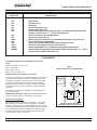
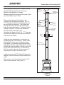
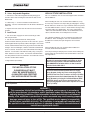
R
DV400S
DIRECT VENT ROOM HEATER
OWNER’S MANUAL
AND INSTALLATION INSTRUCTIONS
WARNING!
If the information in this manual is not followed exactly,
a fire or explosion may result causing property damage, personal injury or loss of life.
-Do not store or use gasoline or other flammable vapors and liquids
in the vicinity of this or any other appliance.
-WHAT TO DO IF YOU SMELL GAS
•
Do not try to light any appliance.
•
Do not touch any electrical switch.
•
Do not use any phone in your building.
•
Immediately call your gas supplier from a neighbor’s phone.
Follow the gas supplier’s instructions.
•
If you cannot reach your gas supplier, call the fire department.
-Installation and service must be performed by a qualified installer,
service agency or the gas supplier.
WARNING!
Improper installation, adjustment, alteration, service
or maintenance can cause injury or property damage. Refer to this manual. For assistance or additional information, consult a qualified installer, service agency or the gas supplier.
FOR YOUR SAFETY
The appliance area must be kept clear and free from combustible materials, gasoline and other flammable vapors and
liquids.
This appliance may be installed in an aftermarket,
permanently located, Manufactured (Mobile) Home,
where not prohibited by Local Codes.
This appliance is only for use with the type of fuel
indicated on the Rating Plate. This appliance is not
convertible for use with other gases, unless a certified Conversion Kit is used.
This manual must be used for installation of the DV400S Direct Vent Heater and retained by the homeowner for operating and
maintenance instructions. This heater may be installed with a vertical or horizontal direct vent terminator system.
Tested and
Listed by
O-T L
Beaverton
Oregon USA
C
OMNI-Test Laboratories, Inc.
1445 North HIghway
Colville, WA 99114
A Division of Hearth Technologies Inc.
#30211C
March 4, 2002
[email protected]
R
DV400S DIRECT VENT ROOM HEATER
Aladdin Hearth Products welcomes you to our tradition of excellence! In choosing a Quadra-Fire appliance, you
have our assurance of commitment to quality, durability, and performance.
This commitment begins with our research of the market, including ‘Voice of the Customer’ contacts, ensuring we
make products that will satisfy your needs. Our Research and Development facility then employs the world’s most
advanced technology to achieve the optimum operation of our stoves, inserts and fireplaces. And yet we are oldfashioned when it comes to craftsmanship. During manufacturing each unit is meticulously fabricated and gold
surfaces are hand-finished for lasting beauty and enjoyment. Our pledge to quality is completed as each model
undergoes a quality control inspection. Additionally, we feel it is important to offer you several finishing options and
accessories to compliment your home’s décor, individualize the use of your appliance, and provide financial options
in acquiring a quality hearth appliance. Ask your Quadra-Fire Dealer for information on these options. From
design, to fabrication, to shipping; our guarantee of quality is more than a word, it’s Quadra-Fire tradition, and we
proudly back this tradition with a Lifetime Warranty.
Prior to installation, we ask you to take a few moments to read this manual. It has been our experience that your
overall enjoyment of your new appliance will be greatly enhanced by becoming familiar with its installation,
operation and maintenance requirements. We wish you and your family many years of enjoyment in the warmth
and comfort of your hearth appliance. Thank you for choosing Quadra-Fire.
With warm regards,
March 4, 2002
______________________
Group Vice President
______________________
Vice President
Research & Development
_____________________
Vice President
Marketing & Product Planning
_______________________
Controller
______________________
General Manager
______________________
Quality / Technical
Support Manager
_______________________
Manufacturing Engineer
Manager
_______________________
Central Sales Manager
______________________
Eastern Sales Manager
_______________________
Order Fulfillment Manager
_______________________
Sr. Purchasing Agent
______________________
Human Resources &
Community Relations
Page 2
30211C
R
DV400S DIRECT VENT ROOM HEATER
Table of Contents
OWNER'S NOTES:
Important!
Complete now for future reference.
MODELNAME
DV400S
Serial Number
Located on the Ratings Label on back of unit.
Date Purchased
Dealership Where Purchased
Safety Precautions
4
Listings and Code Approvals
5
Ratings Label
5
Description of the DV400S Room Heater
6
Heater System Components
7
Clearances
8
Termination
9
A. Horizontal Termination
10-13
B. Vertical Termination
14-16
C. Existing Masonry Chimney Installation
16-17
D. Existing Class A Metal Chimney
Dealer Phone
Installation
Additional Information:
Gas Line Installation
19
Gas Pressure
19
Field Fuel Conversion
19
High Altitude Conversion
20
Optional Accessories
21-22
Firebox Entry
23-24
Lighting Instructions
25-26
Maintenance Instructions
Trouble Shooting
After completing your warranty card, attach your sales receipt
and warranty stub here for future reference.
March 4, 2002
Page 3
17-18
27
28-29
Replacement Parts
29
Lifetime Warranty
30
30211C
R
DV400S DIRECT VENT ROOM HEATER
PLEASE RETAIN THIS MANUAL FOR FUTURE REFERENCE.
Safety Precautions
1. PLEASE READ THESE INSTALLATION INSTRUCTIONS COMPLETELY BEFORE BEGINNING INSTALLATION PROCEDURES.
FAILURE TO FOLLOW THEM COULD CAUSE AN APPLIANCE MALFUNCTION RESULTING IN SERIOUS INJURY AND/OR
PROPERTY DAMAGE.
2. DUE TO HIGH TEMPERATURES THE APPLIANCE SHOULD BE LOCATED OUT OF TRAFFIC AND AWAY FROM FURNITURE
AND DRAPERIES.
3. CHILDREN AND ADULTS SHOULD BE ALERTED TO THE HAZARDS OF HIGH SURFACE TEMPERATURES AND SHOULD STAY
AWAY TO AVOID BURNS OR CLOTHING IGNITION.
4. YOUNG CHILDREN SHOULD BE CAREFULLY SUPERVISED WHEN THEY ARE IN THE SAME ROOM AS THE APPLIANCE.
5. CLOTHING OR OTHER FLAMMABLE MATERIAL SHOULD NOT BE PLACED ON OR NEAR THE APPLIANCE.
6. ANY SAFETY SCREEN OR GUARD REMOVED FOR SERVICING AN APPLIANCE MUST BE REPLACED PRIOR TO OPERATING
THE APPLIANCE.
7. WARNING: DO NOT OPERATE APPLIANCE WITH THE PANEL(S) REMOVED, CRACKED OR BROKEN. REPLACEMENT OF THE
PANEL(S) SHOULD BE DONE BY A LICENSED OR QUALIFIED SERVICE PERSON.
8. INSTALLATION AND REPAIR SHOULD BE DONE BY A QUALIFIED SERVICE PERSON. THE APPLIANCE SHOULD BE
INSPECTED BEFORE USE AND AT LEAST ANNUALLY BY A QUALIFIED SERVICE PERSON. MORE FREQUENT CLEANING
MAY BE REQUIRED DUE TO EXCESSIVE LINT FROM CARPETING, BEDDING MATERIAL, ETC. IT IS IMPERATIVE THAT
CONTROL COMPARTMENTS, BURNERS AND CIRCULATING AIR PASSAGEWAYS OF THE APPLIANCE BE KEPT CLEAN.
9. ENSURE THAT THE FLOW OF COMBUSTION AND VENTILATION AIR NOT BE OBSTRUCTED.
10. ENSURE THAT ADEQUATE COMBUSTION AND VENTILATION AIR ARE PROVIDED.
NOTE: Illustrations throughout these instructions reflect typical installations and are for design purposes only. Actual
installation may vary slightly due to individual design preferences. However, minimum and maximum clearances
must be maintained at all times.
The illustrations and diagrams used throughout these installation instructions are not drawn to scale.
March 4, 2002
Page 4
30211C
R
DV400S DIRECT VENT ROOM HEATER
LISTING & CODE APPROVALS
U.S. CERTIFICATION
The DV400S Series Room Heater has been tested in accordance with the
ANSI standard Z21.88 1998 and UL307B and has been listed by OMNITest Labs for installation and operation as described in these installation
and operation instructions. All components are A.G.A. or UL safety
certified.
Canada Certification
The DV400S Series Room Heater has been tested in accordance with
CSA 2.33-M98 and has been listed by OMNI-Test Labs for installation and
operation as described in these installation and operating instructions. All
components are C.G. A. or C.S.A. safety certified.
This Heater is approved for installation in bedrooms and mobile
homes in the United States and Canada.
Local Codes
This installatin must conform with local codes or, in the absence of local codes,
with theNational Fuel Gas Code, ANSI Z223.1-latest edition, in the U.S.A. and the
CAN/CGA B149-latest edition, in Canada.
Efficiency
The efficiency rating of the appliance is a product thermal efficiency
rating determined under continuous operating conditions and was determined
independently of any installed system.
SERIAL/RATING LABEL
Listed by
C
O -T L
MODEL / MODELE: DV400S VENTED GAS FIREPLACE HEATER
SERIAL NO.
FOURNAISE AU GAZ AVEC VENTILATION
NOT FOR USE WITH SOLID FUEL /
NE PAS UTILISER AVEC LE COMBUSTIBLE SOLIDE
Beaverton
Oregon USA
OMNI-Test Laboratories, Inc.
Report No. / Rapport Numero
061-S-22-4
A Division of Hearth Technologies Inc.
1445 North Highway Colville,
WA 99114
APPROVED FOR CANADA AND USA TO: ANSI Z21.88-1998 / CSA 2.33-M98 Vented Gas Fireplace Heaters, and applicable sections of UL307b Gas Burning Heating Appliances for
Manufactured Homes and Recreational Vehicles, CAN/CGA 2.17-M91 “Gas Fired Appliances for use at High Altitudes.” This appliance is manufactured for operation with Natural Gas.
For conversion to propane Manufacturer’s Part #844-8230 and instructions must be used. This appliance may be installed in a bedroom or bedsitting room; in Canada remote
thermostat installation is required.
APPROUVÉ POUR LE CANADA ET LES ÉTATS-UNIS: ANSI Z21.88-1998 / CSA 2.33-M98 Fournaises au Gaz avec Ventilation, et les sections applicables de UL 307b Appareils de
Chauffage Au Gaz pour les Maisons Mobiles et les Véhicules Motorisés, CAN/CGA 2.17-M91 “Gas Fired Appliances for use at High Altitudes”. Cet appareil est manufacturé pour
l’opération avec le Gaz Naturel. Pour une conversion au gaz propane les pièces du Manufacturier #844-8240 et ses instructions doivent être utilisées. Cet appareil peut être utilisé
dans une chambre à coucher ou salle de séjour; au Canada, l’installation d’un thermostat à distance est exigée.
FAN TYPE VENTED CIRCULATOR / VENTILATEUR CIRCULATOIRE Opt. Blower Part #844-0150
Blower Electrical Rating / Évaluation du Ventilateur Électrique: 115 V., 1.5 Amps, 60 Hz, 150 Watts
Thermal Efficiency / Efficacité Thermique 77% NG
Input Rate on “HI” (BTU/Hr)
Puissance Évaluée à “HI” (BTU/Hr)
Input Rate on “LO” (BTU/Hr)
Puissance Évaluée à “LO” (BTU/Hr)
Maximum Output (BTU/Hr)
Puissance Maximum (BTU/Hr)
Main Burner Orifice
Orifice du Brûleur Principal
For use with Natural Gas
Usage Au Gaz Naturel
0-4500’
29,500
For use with Propane
Usage Au Gaz Propane
0-4500’
28,500
19,500
24,000
22,700
22,500
.106/2.69 DIA./mm
.063/1.60 DIA./mm
Minimum Inlet Pressure (Inches W.C.)
4.5”
Pression Minimum de la Valve (pouces W.C.)
Maximum Inlet Pressure (Inches W.C.)
7.0”
Pression Maximum de la Valve (pouces W.C.)
Manifold Pressure on “HI” (Inches W.C.)
3.5”
Pression du Collecteur d’ Échappement à “HI” (pouces W.C.)
11”
14”
10”
This appliance equipped for altitudes 0-2000’ (0-610m) in USA; and in Canada for altitudes of 0-4500’ (0-1370m). In USA for Altitudes above
2000’, the vent configuration, orifice, or combination of both may need to be changed. See Owner’s Manual for information on making these
changes. Cet appareil est équipé pour les altitudes de 0-2000’ (0-610m) aux États-Unis; et au Canada pour les altitudes de 0-4500’ (0-1370m).
Pour les altitudes au dessus de 2000’ aux États-Unis, la configuration du ventilateur, son orifice ou les deux peuvent possiblement avoir à être
changé. Voyez le manuel du propriétaire pour les informations sur ces changements.
This appliance must be installed in accordance with local codes, if any; if none, follow ANSI Z223.1 in USA, CAN 1-B149 in Canada.
This appliance is only for use with the type of gas indicated on the rating plate and may be installed in an aftermarket, permanently located,
manufactured (mobile) home where not prohibited by local codes. See owner's manual for details. This appliance is not convertible for use with other
gases, unless a certified kit is used. Cet appareil doit etre utilise uniquement avec le type de gaz indique sur la plaque signaletique et peut etre installe
dans une maison prefabriquee (mobile) installee a demeure si les reglements locaux le permettent. Voir la notice du proprietaire pour plus de details. Cet
appareil ne peut etre converti a d'autres gaz sauf si une trousse de conversion certifiee est utilisee.
This appliance must be properly connected to a venting system in accordance with the manufacturer's installation instructions. If venting is disconnected
for any reason, the vent-air intake system must be properly resealed and reinstalled.
Cet appareil doit ê correctement raccordé á un système d'évacuation, conformément aux instructions du fabricant.
Keep burner and control compartment clean. See installation and operating instructions accompanying this appliance. Gardez le brûleur et le
compartiment de contrôle propres. Vérifiez les instructions d’installation et d’opération qui accompagnent cet appareil. This vented gas fireplace heater
is not for use with air filters. / Cet appareil de chauffage au gaz n’est pas pour l’usage avec des filtres d’air
DO NOT REMOVE THIS LABEL /
NE PAS ENLEVER L’ÉTIQUETTE
2001
March 4, 2002
2002
Date of Manufacture / Date du Manufacturier
2003
Jan
Feb
Mar
Apr
May
Jun
Page 5
Jul
Aug
Sep
Oct
Nov
Dec
Made in U.S.A. /
Fait Aux États-Unis
250-5911
30211C
R
DV400S DIRECT VENT ROOM HEATER
DESCRIPTION OF THE HEATER SYSTEM
The DV400S is a Direct Vent Room Heater. Combustion air is supplied from outside, not from
inside the house as with other types of heaters.
TYPICAL ASSEMBLY
The installation of this Quadra-Fire DV400S
system consists of the following:
ROUND
SUPPORT
BOX/WALL
THIMBLE
HORIZONTAL
TERMINATION
CAP
VENT
SECTION
1. Appliance
2. Venting System
3. Termination
90û ELBOW
VENT
SECTION
VERTICAL
TERMINATION
CAP
STORM
COLLAR
FLASHING
Optional Components include:
FIRESTOP
SPACER
1. Blower Kit
2. Decorative Glass Accent
3. Warming Shelf
4. Remote Control
ROUND
SUPPORT
BOX/WALL
THIMBLE
CATHEDRAL
CEILING
SUPPORT
BOX
VENT
SECTION
NOTE: Operation of a Direct Vent Heater
may be sporadic in high wind situations.
DV400S - With Optional BK95
March 4, 2002
DV400S Front View
Page 6
30211C
R
DV400S DIRECT VENT ROOM HEATER
HEATER SYSTEM COMPONENTS
839-0710
844-0150
844-0140
844-7850
844-7950
844-7960
844-8230
844-8240
DV400S, Matte Black, NG
Fan Kit, BK95, Var. Speed, Thermostat “ON/OFF”
Decorative Glass accent - gold, DT6G
Warming Shelf, Matte Black (pr.)
Warming Shelf Bracket - w/mitten rod, Black (pr.)
Warming Shelf Bracket - w/mitten rod, Gold (pr.)
LP Conversion Kit, SPCK400S
NG Conversion Kit, SNCK400S
SECURITY CHIMNEY'S SECURE VENT CHIMNEY SYSTEM
Your Quadra-Fire DV400S has been approved with Security Chimney's Secure Vent Chimney System. Please
contact your local dealer and they will advise you of the required parts needed for your installation. All the required
certification tests have been successfully completed with OMNI-Test Laboratories, Inc.
SIMPSON DURA-VENT PARTS LIST
Pipe cont'd
Termination Caps & Snorkels:
991
High Wind Vertical Termination Cap
986
High Wind Horizontal Termination Cap
980
Vertical Termination Cap w/Wind Halo
983
Vertical Termination
984
Horizontal Termination Cap
981
Snorkel Termination (36”)
982
Snorkel Termination (14”)
950
Vinyl Siding Standoff
Flashing:
941
943
943S
943F
Misc.
Cathedral Ceiling Support Box
Flashing, 0/12 to 6/12 Roof Pitch
Flashing, 7/12 to 12/12 Roof Pitch
Flashing, Flat Roof
908
908B
907
907B
906
906B
904
904B
903
903B
902
902B
911
911B
912
912B
March 4, 2002
17” -24” Pipe, Adj. Glav.
17” -24” Pipe, Adj.Blk.
45° Elbow, Galv.
45° Elbow, Black
90° Elbow, Galv.
90° Elbow, Black
953
963
988
9546
942
Storm Collar
Ceiling Firestop
Wall Strap
Attic Insulation Shield
Wall Thimble/Cathedral Ceiling Collar
SDV KITS
970A
Support Boxes/Thimbles:
940
Round Ceiling Support/
Wall Thimble Cover
941
Cathedral Ceiling Support Box
Pipe:
917
917B
945
945B
990
990B
971HW
973
6” Pipe Length, Galv.
6” Pipe Length, Black
9” Pipe Length, Galv
9” Pipe Length, Black
12” Pipe Length, Galv.
12” Pipe Length, Black
24” Pipe Length, Galv.
24” Pipe Length, Black
36” Pipe Length, Galv.
36” Pipe Length, Black
48” Pipe Length, Galv.
48” Pipe Length, Black
11” -14 5/8” Pipe, Adj. Glv.
11” -14 5/8” Pipe, Adj. Blk.
12” - 17” Pipe, Adj. Glv.
12” - 17” Pipe, Adj. Blk
Standard Termination Kit includes
1 each of:“ 990B, 940, & 985
See Note #1 below.
Standard Termination Kit includes
1 each of:“990B, 940, 985, 904B, 911B
Vertical Termination Kit includes 1 each
of:“943, 953, 991 (support box NOT included)
Note #1: Straight pipe lenghts are needed to complete installation, the
black 45° elbow is NOT included in kit.
The following venting parts are available from your Dealer:
HHW2
HHW2K
Horizontal High Wind Cap
Horizontal Kit includes 90° Black Elbow,
Wall Thimble, 24" Black Pipe, 11" - 14
5/8" Adjustable Vent, HHW2 Termination Cap.
The VTA1, Vertical Termination Adapter Kit, may also be
safely used with this Heater. It is composed of a Vertical
Termination Cap and Cover Plate for existing vertical
chimney.
Page 7
30211C
R
DV400S DIRECT VENT ROOM HEATER
DURA-VENT GS
CATALOG #
953
963
988
981
982
971
980
984
909B
950
3951
3960
HHW2
HHW2K
VENTING SYSTEM COMPONENTS
DESCRIPTION
Storm Collar
Firestop Spacer
Wall Strap
Snorkel Termination (36")
Snorkel Termination (14")
Horizontal Kit (Horizontal Termination Cap, One 90 Degree Black Elbow, Wall
Thimble, 24" Black Pipe, 11" - 14 5/8" Adjustable Vent
Vertical Termination Cap with Wind Halo
Horizontal Termination Cap
Retrofit Adjustable Chimney Connector Retrofit Chimney Connector Plate
VSS - Vinyl Siding Standoff/Shield
Round Ceiling Support/Wall Thimble Trim Kit, Polished Brass
Cathedral Ceiling Support Trim Kit, Polished Brass
Horizontal High Wind Cap (recommended for optimal performance)
Horizontal Kit (One 90 degree Elbow, Wall Thimble, 24" Black Pipe, 11" - 14 5/8"
Adjustable Vent, HHW2 Termination Cap.
CLEARANCES
The following clearances to combustibles must be maintained:
Minimum clearances to the floor - 0"
Figure 1
Minimum Clearances To Combustibles
Back of unit to wall - 6”
Sides of unit to wall - 6
Base of the unit to ceiling - 72".
Minimum clearances to Venting are as follows:
6"
4"
6"
STOVE
4"
6"
This appliance is certified for installation in a bed/sitting room in
the U.S. and Canada.
Mobile Home Installations. Appliances installed in Mobile Homes
must be secured to the floor in a minimum of two locations.
VE
O
ST
Horizontal runs require a 1-1/2” minimum Air Space on the top and
an 1/2” minimum Air Space on the sides and bottom of the outer
Vent Section. If an Elbow is being used,in an enclosed wall, floor
or ceiling, a top Air Space clearance of 3” must be maintained.
Vertical rise sections require a 1” minimum Air Space completely
around the Vent section. These clearances must be maintained
at all times.
6"
STOVE
48"
MAX.
Positioning the Appliance.
This appliance may be placed on a combustible or non-combustible continuous, flat surface. When the appliance is installed
directly on carpeting, tile or other combustible material other than
wood flooring, the appliance shall be installed on a metal or wood
panel extending the full width and depth of the appliance. Slide
the Heater into position and level the Heater from side-to-side
and front-to-back. Shim as necessary.
March 4, 2002
Page 8
HEARTH PROTECTION IS NOT
NECESSARY ON THIS GAS HEATER.
30211C
R
DV400S DIRECT VENT ROOM HEATER
TERMINATION
Four types of Termination are possible for this Heater: Horizontal, Vertical, Existing Masonry or Existing Class A
Class A Metal Chimney
Vertical Flat Ceiling
Cathedral Ceiling
Horizontal Termination
COMMON INSTALLATIONS
March 4, 2002
Page 9
30211C
R
DV400S DIRECT VENT ROOM HEATER
A. Horizontal Termination
Refer to Chart A and Figure 2 for horizontal venting recommendations. The
minimum vertical rise allowed for horizontal termination is 2" from the top of the
heater. The maximum horizontal run allowed for venting is 15' with a minimum
4' rise.
Note: Horizontal runs will require the use of one
vent support for every 3' of vent.
A single vertical to horizontal elbow is already calculated into the allowable 15' run.
Each additional elbow reduces the maximum horizontal distance by 3' feet.
V
E
R
T 16'
I
C Thru
A
4'
L
Example: When using three elbows, the maximum horizontal distance has been
reduced to 9' (3 - 1 = 2 elbows x 3' = 6'; 15' max. - 6' of elbows = 9' of horizontal
run.) Even with only these three elbows ( the equivalent of 6' additional horizontal
feet) you now need a minimum of 4' of vertical rise. See Chart A.
R
I
S
E
If a vertical - to - horizontal elbow is enclosed within a wall, floor or ceiling, an air
space clearance of 3" must be maintained.
Due to the many different combinations that can be used when constructing
venting, the number of vent sections required can only be determined by the
installer.
Horizontal venting must terminate within the shaded area shown in Fig. 2. Chart
A illustrates the figures included in that shaded area. For example, if your vertical
rise is the minimum two feet, venting can terminate anywhere between 20 - 1/2"
(includes wall thickness and assumes 4", and venting required to termination cap)
and 10' feet.
15' MAX. HORIZONTAL RUN
2' 3' 4' 5' 6' 7' 8' 9' 10' 11' 12' 13' 14' 15'
X X X X X X X X X X X X X X
X X X X X X X X X X X X X X
3'
X X X X X X X X X X X X X X
X X X X X X X X X
2'
X X X X X X X X X
CHART A - Venting Combinations
Note: A horizontal run of vent must have a 1/4"
rise for every 1 ft. of run towards the termination.
Never allow the vent to run downward. This could
cause high temperatures and the possibility of a
fire.
VENTING CAN ONLY TERMINATE
WITHIN THIS AREA.
15' MAX.
Venting termination must not be recessed into the wall or siding. Fig 3 on Page 9
illustrates termination cap location and minimum dimensions for each termination
application. Or follow ANSI Z223.1, latest edition.
16'
MAX.
4'
2'
MIN.
29"
591/2"*
15" MIN.
* MINIMUM VENT
HEIGHT (CENTER)
(SEE NOTE)
10' MAX.
Fig. 2 - Horizontal Lenth
March 4, 2002
Page 10
30211C
R
DV400S DIRECT VENT ROOM HEATER
Fig. 3 - HORIZONTAL TERMINATION REQUIREMENTS
A. *12” (30cm) minimum: Clearance above grade, veranda, porch, deck, or balcony.
B. *12” (30cm) minimum: Clearance to window or door that may be opened.
C. 12” (30cm) minimum: Clearance to permanently closed window (recommended to prevent condensation on window)
or window that may be opened.
D. 18” (46cm) minimum: Vertical clearance to ventilated soffit located above the terminal within a horizontal distance
of 2’ (60cm) from the centerline of the terminal.
E. 12” (30cm) minimum: Clearance to unventilated soffit.
F. Clearance to outside corner. Clearance in accordance with local installation codes and the requirements of the
gas supplier.
G. Clearance to inside corner. Clearance in accordance with local installation codes and the requirements of the
gas supplier.
H. *Not to be installed above a meter/regulator (gas or electrical) assembly within 3’ (90cm) horizontally from the
centerline of the meter/regulator.
I. 3’ (91cm) USA/6' (183cm)Canada minimum: Clearance to service regulator vent outlet.
J. 12" (30cm) minimum: Clearance to nonmechanical air supply inlet to building or the combustion air inlet to any
other appliance.
K. 3’ (91cm) USA/6' (183cm)Canada minimum: Clearance to a mechanical air supply air inlet.
L. *+7’ (2.1m) minimum: Clearance above paved sidewalk or a paved driveway located on public property.
M. *#12” (30 cm) minimum: Clearance under veranda, porch, deck, or balcony.
N. Clearance to adjacent building or deck. Clearance in accordance with local installation codes and the requirements
of the gas supplier.
+ A vent shall not terminate directly above a sidewalk or paved driveway which is located between two single-family dwellings
and serves both dwellings.*
# Only permitted if veranda, porch, deck, or balcony, is fully open on a minimum of two sides beneath the floor.*
* As specified in CGA B149 Installation Codes
Note: Local Codes or regulations may require different clearances.
D
E
V
N
L
V
B
Openable
V
F
Fixed
Closed
H
B
A
K
C
I
V
M
A
G
J
V
A
V = vent terminal
March 4, 2002
A = air supply inlet
Page 11
= area where terminal is not permitted
30211C
R
DV400S DIRECT VENT ROOM HEATER
1. Preparing the Wall for Horizontal
Termination.
Figure 4 - Exterior Wall Hole
A hole measuring 10” wide and 10” high must be cut
and framed in the exterior wall where venting will be
terminated.
EXTERIOR
WALL
The height of the hole must be located to meet all
local and national codes and not be easily blocked
591/2''
541/2''
or obstructed. The minimum height to the center of
the horizontal vent is 591/2'' from the base of the unit.
This figure will increase by the length of each verti-
HOLE TO BE
VENTED
THROUGH
cally positioned vent section added to the venting
10''x 10'' DURAVENT MINIMUM
system. See Figure 4.
Figure 5 - Twist-lock procedure
2. Assembling Venting Sections.
Use only vent supplied or listed for use with this
Female
Locking
Lugs
Heater. To attach a straight section to the top of
the Heater, female end down, slide the pipe over the
outer Collar on the Heater while the inner flue will slip
over the Vent Inner.
Male
Locking
Lugs
MAINTAIN MINIMUM CLEARANCES OR
GREATER AROUND THE VENT SYSTEM. Do not
pack air spaces with insulation or other material.
If the wall being penetrated is constructed of noncombustible material (i.e.: masonry block or concrete) a 7 inch diameter hole is acceptable. It is
recommended that for masonry walls the vent be
wrapped with fiberglass insulation to prevent contact
with the masonry as the contact promotes premature
deterioration of the vent.
March 4, 2002
NOTE: For buildings with vinyl siding, a Vinyl
Siding Standoff should be installed between
the vent cap and the exterior wall. Attach
the Vinyl Siding Standoff to the Horizontal
Vent Termination. The Vinyl Siding Standoff
prevents excessive heat from possible melting the vinyl siding material. NOTE: The
HHW2 cap incorporates it's own vinyl siding
standoff. See Fig. 8.
Page 12
30211C
R
DV400S DIRECT VENT ROOM HEATER
The Dura-Vent GS is unitized and twist-locks together. For the twist-lock procedure, consult Figure 5 and
do the following:
(1) Four indentations, located on the female ends of pipes and fittings, are designed to slide straight onto
the male ends of adjacent pipes and fittings, by orienting the four pipe indentations so they match and slide
into the four entry slots on the male ends. See Figure 5. Push the pipe sections completely together, then
twist-lock one section clockwise approximately one-quarter turn, until the two sections are fully locked. The
female locking lugs will not be visible from the outside, on the Black Pipe or fittings. They may be located
by examining the inside of the female ends.
(2) Horizontal runs of vent must be supported every three feet. Wall Straps are available for this purpose.
Before connecting the horizontal run of vent pipe to the vent termination, slide the black decorative wall
thimble cover over the vent pipe.
When using the adjustable section, maintain a 1” overlap on pipe sections and secure. It is also important that
the vent pipe extends a minimum of 1 1/2” into vent cap.
3. Termination Cap. Position the horizontal vent termination so that 1 1/2” clearance is maintained on top
of the vent sections and 1 1/2” on sides.
Before attaching the Vent Termination to the exterior wall, run a bead of non-hardening mastic around the
outside edges to make a seal between the Cap and the wall.
Attach Cap to exterior wall with four (4) wood screws, making sure that arrow on Cap is pointing up. After Cap
is attached, make sure that a 1 1/2” is maintained from top of vent to combustibles.
Secure the connection between the vent pipe and the vent cap by attaching the two sheet metal strips
extending from the vent cap assembly into the outer wall of the vent pipe. Use the two sheet metal screws
provided to connect the strips to the pipe section. Bend any remaining portion of the sheet metal strip back
towards the vent cap, so it will be concealed by the decorative wall thimble cover. See Fig.6.
Slide the Decorative Wall Thimble up the wall surface and attach with the screws provided. Apply Decorative
Brass or Chrome Trim if desired. See Fig. 7.
4. Vertical Rise on the Exterior. For installations requiring a vertical rise on the exterior of a building, 14”
and 36” tall Snorkel Terminations are available. Follow the same installation procedures that are used for the
standard horizontal termination found in Step 3.
March 4, 2002
Page 13
30211C
R
DV400S DIRECT VENT ROOM HEATER
Figure 6 - Insertion of Vent Pipe
WALL
THIMBLE
B. Vertical Termination.
The following figures are the maximum distances
from the top of the unit, as well as the minimum air
space clearances that must be maintained: Maximum
straight unsupported rise - 25'; Maximum height - 40'
from the top of the unit. Maximum horizontal unsupported run - 3'; air space clearances around vertical
venting - 1" on all sides; air space clearances around
horizontal venting - 11⁄2" on top and 1⁄2" on sides
and bottom. If an elbow is being used in an enclosed
wall, floor, or ceiling a top air space clearance of
3" must be maintained. These clearances must be
maintained at all times.
STRAP
Figure 7 - Decorative Wall Thimble
Wood Screws
Figure 8 - Vinyl Standing Standoff
VINYL
SIDING
APPLY SEALANT TO ALL
FOUR SIDES
SCREW
BOLT HORIZONTAL
TOP TO VINYL
STANDOFF
1. Position the Heater.
Position the heater in its desired location. Maintain
all clearances to combustibles.
2. Preparing the Ceiling.
Drop a plumb bob down from the ceiling to the position of the heater flue exit and mark the location
where the vent will penetrate the roof. Drill a small
hole at this point. Next drop a plumb bob from the
roof to the hole previously drilled in the ceiling and
mark the spot where the vent will penetrate the roof.
Determine if ceiling joists, roof rafters, or other framing will obstruct the venting system. You may wish to
relocate or offset the appliance to avoid cutting load
bearing members.
To bypass any overhead obstructions the vent system may be offset using a 45° elbow or a 90° elbow.
Vent stabilizers have straps for securing these parts
to joists or rafters. lumbers tape may be purchased
locally and used in conjunction with vent stabilizers.
See Fig. 9.
3. Assembling vent sections. Only use vent supplied and listed for use with this Heater.
Figure 9 - Elbows with Stabilizer
90¡ ELBOW
VINYL SIDING
STANDOFF
March 4, 2002
90¡ ELBOW
VENT
STABILIZER
Page 14
30211C
R
DV400S DIRECT VENT ROOM HEATER
To attach a straight section to the top of the
Heater, with the female end down, slide that pipe
over the outer Collar on the Heater while the Vent
Inner slips into the Flue of the Heater.
MAINTAIN MINIMUM 1" CLEARANCES OR
GREATER AROUND THE VENT SYSTEM.
Do not pack air spaces with insulation or other
material.
The Dura-Vent GS is unitized and twist-locks
together. For the twist-lock procedure, consult
Figure 5 and do the following:
(1) Four indentations, located on the female ends
of pipes and fittings, are designed to slide straight
onto the male ends of adjacent pipes and fittings,
by orienting the four pipe indentations so they
match and slide into the four entry slots on the
male ends. (Figure 5.) Push the pipe sections
completely together, then twist-lock one section
clockwise approximately one-quarter turn, until
the two sections are fully locked. The female
locking lugs will not be visible from the outside, on
the Black Pipe or fittings. They may be located by
examining the inside of the female ends.
(2) Horizontal runs of vent must be supported
every three feet. Wall Straps are available for this
purpose.
Assemble the desired lengths of black pipe and
elbows. It is necessary to reach from the Heater
up through the round support box. Ensure that
all pipe and elbow connections are in their fully
twist lock position.
Using the mark from Step 2, drive a nail up
through the roof to mark the center. Measure
to either side of the nail and mark the opening
required. This is measured on the horizontal;
actual length may be larger depending on the
pitch of the roof. Cut out and frame the opening.
See chapter 25 of the Uniform Building Code
March 4, 2002
for Roof Framing details. A one inch minimum air
space clearance must be maintained between the
vent system and the roof.
Assemble lengths of pipe and elbows necessary to
reach from the ceiling support box up through the roof
line. Galvanized pipe and elbows may be utilized
in the attic, as well as above the roof line. The
galvanized finish is desirable above the roof line due
to its higher corrosion resistance.
4. Installing the Roof Flashing or Site-Produced
Chase Top. Position a Roof Flashing (or construct
a Chase and Chase Top) and secure in place with
nails.
Continue to add Vent sections through the Roof
Opening, maintaining at least 1” Air Space clearance.
Major Building Codes specify a minimum Vent
(Chimney) height above the Roof top depending on
Roof Pitch. See Figure 10. Add Pipe sections
until the height of the Vent Cap meets the minimum
Building Code requirements described in Figure 10.
Note that for steep roof Pitches, the vent height must
be increased.
These Vent System heights are necessary in the
interest of safety, however, they do not ensure draftfree operation. Trees, buildings, adjoining Roof lines,
adverse wind conditions, etc., may create a need for
a taller Vent System should down drafting occur.
5. Termination Cap. Twist lock the Vent Cap.
WARNING!
THIS APPLIANCE MAY ONLY USE THE APPROVED
VENTING SYSTEMS SHOWN IN THESE
INSTALLATION INSTRUCTIONS. IT MUST NOT BE
CONNECTED TO CHIMNEY FLUE SERVICING A
SEPARATE SOLID FUEL OR GAS FUEL BURNING
APPLIANCE.
Page 15
30211C
R
DV400S DIRECT VENT ROOM HEATER
EXHAUST
HORIZONTAL OVERHANG
INTAKE AIR
VERTICAL WALL
2 Ft.
Min.
LISTED
CAP
2 Ft. Min.
4'' UL 1777 LISTED
GAS VENT INNER
FLEX LINER
LOWEST
DISCHARGE
OPENING
X
12
WALL THIMBLE/
TRIM COLLAR
ROOF PITCH IS X/12
SEAL WITH SILICONE
SEAL WITH SILICONE
H (MIN.)-MINIMUM HEIGHT
FROM ROOF TO LOWEST
DISCHARGE OPENING
Roof Pitch
flat to 6/12
6/12 to 7/12
over 7/12 to 8/12
over 8/12 to 9/12
over 9/12 to 10/12
over 10/12 to 11/12
over 11/12 to 12/12
over 12/12 to 14/12
over 14/12 to 16/12
over 16/12 to 18/12
over 18/12 to 20/12
over 20/12 to 21/12
24" MINIMUM
VERTICAL HEIGHT
DURA-VENT GS
VENTING
6"
INSIDE CHIMNEY
DIAMETER
6" MINIMUM
H (min.) ft.
1.0
1.25
1.5
2.0
2.5
3.25
4.0
5.0
6.0
7.0
7.5
8.0
Figure 11
Adaptation to Masonry Chimney
Figure 10 -Vent (Chimney) Height
C. Existing Masonry Chimney Installation
WARNING
WHEN VENT SECTIONS EXCEEDING 3 FEET
IN LENGTH ARE INSTALLED BETWEEN AN
OFFSET/RETURN, STRUCTURAL SUPPORT
MUST BE PROVIDED TO REDUCE OFF-CENTER
LOADING AND PREVENT VENT SECTIONS
FROM SEPARATING AT THE VENT JOINTS.
March 4, 2002
This installation is subject to local jurisdiction. Some codes may require the use of
another liner for intake air. If so, the 4”
aluminum liner should be inside a 6” UL 181
listed liner.
This Heater can be vented through an existing
Masonry Chimney but the chimney must be lined
with one UL 1777 listed 4” aluminum flexible gas
vent liner for exhaust. The existing Flue will be
used to supply the air intake to the galvanized
steel Flue system. See Figure 11.
Page 16
30211C
R
DV400S DIRECT VENT ROOM HEATER
Before installing the liner system, the chimney passageway should be cleaned and
examined to verify it is unobstructed and in
good structural condition.
Measure and record the chimney dimensions to
determine total flexible liner requirements.
Follow the liner manufacturer’s instructions for
installing the liner in the chimney. Attach a flexible liner puller to the liner and secure a rope
to the puller. One person should feed the liner
through the chimney, and another person should
pull the liner from the bottom, with the rope, guiding the liner down the chimney. After feeding
the liner down the chimney, form a 90˚ angle and
bring the liner through the hole in the chimney
wall. (If running two liners, run the 6” liner first
and then the 4” inside of it.) Extend the liner
through the wall of the chimney and attach it to
the venting system extending from the top of the
Heater.
Construct a metal flashing large enough and
strong enough to cover the chimney opening
and support the Heater Vertical Termination Cap.
VTA
6" LINER (OPTIONAL)
SILICONE SEALANT
RIGID FLASHING
(ATTACHED TO CHIMNEY
WITH SCREWS WITH
SILICONE SEALANT
UNDERNEATH)
Figure 12
Masonry Termination
March 4, 2002
The flashing needs to fold down over and around
the outside of the masonry chimney so that it
can be secured to the chimney by 4 screws.
See Figure 12. The flashing will require a hole
at least 6 1/2'' in diameter. (If using a 6” liner,
extend the 6'' flexible liner through the flashing
and attach it to the VTA (Vertical Termination
Adapter) with screws provided.) Secure the VTA
to the flashing with the screws provided and seal
the VTA/Flashing joint with a silicone sealant to
prevent moisture from running down the liner into
the chimney.
Attach the 4'' gas vent liner to the Vertical
Termination Cap with screws provided, then
attach the Termination Cap to the VTA with
screws provided. See Figure 12.
D. Existing Class A Metal Chimney Termination
In many cases where a Quadra-fire DV400S
is replacing a woodstove, much of the existing
Class A Metal Chimney can be incorporated into
the direct vent system.
The existing chimney must comply with
NFPA-211 codes and any local code requirements.
The chimney should be cleaned and examined to verify it is unobstructed and in good
structural condition. Any structural weaknesses such as cracks, leaky joints, corroded or warped surfaces can have an adverse
effect on the performance of this Heater and
should be replaced or repaired.
Whenever an existing Class A Metal Chimney is
on an outside wall, removal of the chimney and
the use of the minimum horizontal direct vent
termination kit may be less expensive.
Page 17
30211C
R
DV400S DIRECT VENT ROOM HEATER
When using an existing Class A Metal Chimney
the following requirements are necessary:
VERTICAL
TERMINATION
CAP
Minimum size diameter is 6 inches.
VERTICAL
TERMINATION
ADAPTER
Minimum height from the base of the stove to the
top of termination cap is 9 feet.
The vent from the top of the Heater to the
Chimney must be rigid vent sections. A 4'' UL
1777 listed gas vent aluminum flexible liner can
be used inside the chimney. The flexible liner
must be secured to the last rigid section with
three (3) sheet metal screws. A minimum 3 inch
overlap is required. Remove and discard the
existing chimney termination cap.
EXISTING
CLASS A
METAL
CHIMNEY
(6'' MIN. DIAMETER)
UL1777 LISTED
4'' GAS VENT
FLEX LINER
Determine the length of the 4'' UL 1777 listed gas
vent flex liner required to meet the vent sections
at the top of the Heater.
Follow the liner manufacturer’s instructions for
installing the liner in the chimney. Attach a flexible liner puller to the liner and secure a rope
to the puller. One person should feed the liner
through the chimney, and another person should
pull the liner from the bottom, with the rope, guiding the liner down the chimney. Extend and run
DURAVENT GS
VENT SECTIONS
the 4'' gas vent liner down the chimney leaving 10''
extending from the top of the chimney stack.
Install and secure the VTA (Vertical Termination
Adapter) onto the chimney with the brackets provided.
Place and secure the Termination Cap on the VTA
with the screws provided. See Figure 13.
Figure 13
Retro-Fit to Metal
Chimney
March 4, 2002
Page 18
30211C
R
DV400S DIRECT VENT ROOM HEATER
PRE-INSTALLATION PREPARATION
GAS LINE INSTALLATION
The valve is located near the lower right rear corner of the
appliance. (See Figure 14.) Install the gas supply line to the
valve. For ease of installation of the unit to the supply line, a
flexible connector and manual shut - off valve are supplied. The
manual shut - off valve should be installed onto the supply line,
ahead of the flex. All connections must be checked for leaks
with a soap and water solution or gas sniffer.
Valve
GAS PRESSURE
Figure 14 - Access to Valve
For natural gas, the minimum inlet gas supply pressure is 4.5
inches water column, and the maximum inlet gas pressure is
7.0 inches water column, for the purpose of input adjustment.
Input rate is 29,500 Btu/hr. For propane gas, the inlet gas
supply pressure must be at least 11.0 inches water column and
a maximum 14.0 inches water column. Input rate is 28,500
Btu/hr.
Manifold pressure for this heater is 1.6 - 3.5 inches water column for natural gas and 6.3 - 10.0 inches water column for propane gas. This heater has a variable adjust manifold.Pressure
taps are located on the front of the valve for both inlet and
outlet pressure.
screw
Figure A
Figure B
FUEL CONVERSION
For conversion of the DV400S unit, use Kit # 844-8240 to
convert from Natural Gas to LP. or the Kit #844-8230 to
convert from LP to Natural Gas.
A.
1.
2.
3.
B.
1.
2.
C.
1.
2.
3.
D.
1.
2.
Gas and Power Supply.
Shut off the gas supply to the unit.
Unplug the blower cord from the power supply (if installed).
Carefully remove the logs and burner from the
firebox. See Figure A for burner removal.
Burner Orifice.
Adjust air shutter adjustment screw as necessary to allow
removal of the burner orifice.
Loosen and remove the retaining nut on the burner orifice
with a 5/8" wrench. See Figure B.
Replace the Burner Orifice with the .063 LP Main Burner
Orifice supplied in the LP kit. (.106 for NG). Reposition the
air shutter onto the burner orifice. Refer to Page 20, on
the following page, for High Altitude Installation.
Pilot Orifice.
Remove top of pilot hood. See Figure C.
Use a 5/32 allen wrench to remove the pilot injector orifice
and install pilot orifice supplied. (.35 LP) (.62 NG). See
Figure D.
Replace the pilot hood ensuring that it is seated and
aligned.
Re-Assembly
Replace burner into the unit, making sure burner end is
over orifice.
Install logs, replace glass front, plug in blower (if installed)
and turn on gas supply.
Figure C
Figure D
March 4, 2002
Page 19
30211C
R
DV400S DIRECT VENT ROOM HEATER
E. Valve - Adjustable Regulator.
HIGH ALTITUDE INSTALLATION
1. Gain access to the Valve Regulator Head by lifting up on
the Valve Cover and removing the Tabs from the Slots on the
Back Shield.
For U.S. installation, units are tested and approved for elevations
from 0-2000 feet.
2. Follow Steps 1 - 3 in the Instructions included with the
Regulator. Save the Label included in the Kit for later attachment
to the unit.
When installing this unit at an elevation above 2000 feet, it may
be necessary to decrease the input rating by changing the existing
Burner Orifice to a smaller size. Input should be reduced 4 percent
for each 1000 feet above sea level. Check with the local gas utility
for proper Orifice size identification. This unit is shipped with a
.106 in./2.67 mm Main Burner Orifice size for Natural Gas and a
.063 in./1.60 mm orifice size on Propane Gas versions.
3. Replace the Valve Cover after the Valve has been checked
for leaks.
F. Leak Check.
1. Turn on the Gas Supply to the unit to check for gas leaks
with soap and water.
2. Turn the Gas Control Knob to the “Pilot” position.
Push the Knob in all the way and hold. At the same time, push in
the Red Ignitor button repeatedly until the Pilot lights. Never hold
the Gas Control Knob for more than [10] seconds if the Pilot does
not light. Once the Pilot lights, continue to hold the Control Knob
in for 15 seconds. Release the Gas Control Knob and it will pop
back out. Test for leaks at the Pilot Assembly using a soap and
water solution or a a Gas Sniffer. Turn the Gas Control Knob to
the “ON” position and turn the Switch On. Check for leaks around
the Valve and the Burner Orifice.
3. Plug in blower (if installed).
WARNING!
THE INSTALLATION OF THIS
CONVERSION KIT MUST
ONLY BE UNDERTAKEN BY
A QUALIFIED AND CERTIFIED
GAS APPLIANCE INSTALLER.
NOTE: This Heater DOES NOT require a 110VAC supply for operation.
For Canadian installation, units are certified for elevations from
0-4500 feet. When installing this unit at an elevation between
0-4500 feet in Canada, the input rating does not need to be
reduced.
When installing this unit at an elevation above 4500 feet in
Canada, check with local authorities.
Consult your local gas company for assistance in determining the
proper Orifice for your location or refer to ANSI Z223.1-latest edition, Appendix F.
NOTE: This Heater must be electrically wired and
grounded in accordance with Local Codes or, in the
absence of Local Codes, with the National Electric
Code ANSI/NFPA 70-latest edition, or the Canadian
Electrical Code, CSA C22.1.
NOTE: This appliance and its individual Shut - Off
Valve must be disconnected from the Gas Supply
Piping System during any Pressure testing of that
System at Test Pressures in excess of 1/2 psi (3.5kPa).
The appliance must be isolated from the Gas Supply
Piping System by closing its individual Manual Shut
- Off Valve during any Pressure testing of the Gas
Supply Piping System at test levels equal or less than
1/2 psi (3.5 kPa).
WARNING !
This conversion kit shall be installed by a qualified service agency in accordance
with the manufacturer’s instructions and all applicable codes and requirements of the
authority having jurisdiction. If the information in these instructions is not followed
exactly, a fire, explosion or production of carbon monoxide may result causing property
damage, personal injury or loss of life. The qualified service agency is responsible
for the proper installatin of this kit. The installation is not proper and complete until
the operation of the converted appliance is checked as specified in the manufacturer’s
instructions supplied with the kit.
March 4, 2002
Page 20
30211C
R
DV400S DIRECT VENT ROOM HEATER
OPTIONAL ACCESSORIES
Optional accessories may be added now or at a later date.
A. Optional Fan
The Optional Fan Kit (844-0150) requires a 110VAC supply.
Blower Installation:
1. Remove the Knockout Plate from the Backshield of the
DV400S by prying out on the plate and clip or break the
tabs that hold it in place. See Figure 1 below.
Attach here.
2. Remove the tape from the back of the strip of Gasket
Material included with the blower kit, and position the
Gasket over the edge of the opening of the Backshield.
See Figure 2 below. (This will eliminate vibration.)
3. Install the Blower into the Backshield by hooking the
bottom of the Blower Housing into the opening and rock
the top of the Blower forward. Fasten the blower in place
with the screws included in the Fastener Pack. See Figure
4 on this page.
4. Attach the On/Off Switch Box for blower to the
Backshield with the screws provided. See Figure 3, this
page.
5. Plug the Connector on the wiring assembly into the
Receptacle on the top of the Blower Housing. See Figure
4 this page.
Figure 3
Attach On/Off Switch Box for blower
Blower
Receptacle
Figure 1
Removal of Knockout Plate
Figure 4
Fan Installation on Backshield also
showing blower Receptacle
Figure 2
Placing Blower Gasket on Back Shield
March 4, 2002
Page 21
30211C
R
DV400S DIRECT VENT ROOM HEATER
C. Remote Control
A remote control thermostat may be installed on this stove.
Contact your dealer for the correct model.
14212 (1)
20613 (1)
WARNING!
Electrical Grounding Instructions
This appliance is equipped with a three-prong
(grounding) plug for your protection against shock
hazard and should be plugged directly into a properly grounded three-prong receptacle. Do not cut or
remove the grounding prong from this plug.
D. Warming Shelves/Brackets
Please see the Installation Instructions included with the
Shelves. Refer to page 7, Heater System Components, for
ordering purposes.
FAN
3
CONTROL
RED
BLK
M
1
F
F
BLK
F
BLK
23998 (1)
28749 (1)
25580 (1)
18164 (1)
25579 (1)
25385 (1)
WHT
2
F
Blower Wiring Diagram
B. Optional Wall Thermostat
The use of a millivolt Thermostat is allowed. It must be
located within 20 feet of the appliance. In order for the
Thermostat to work, the “ON/OFF” Switch must be in
the “ON” position.
Figure 15 shows how to connect a millivolt Thermostat
without the “ON/OFF” Switch in the Circuit. Disconnect
the “ON/OFF” Switch from the Valve and wire the millivolt
Thermostat as indicated.
Warming Shelf and Bracket
E. Door Trim
Part # 844-0140. Please read the Installation Instructions
included with the Door Trim.
Fan Assembly
Black = B
White =W
Red = R
W
Thermocouple
Ignitor
Gas Pilot
Thermopile
Thermopile
Junction Box
B
W
Convection Air
Temp Switch
Pilot
Assembly
Copper
B
B
B
R
R
W
Fan
Speed
Control
Decorative Glass Accent
Ignitor
Burner
ON/OFF
switch
Valve
Figure 15 - Wiring Diagram
March 4, 2002
Page 22
30211C
R
DV400S DIRECT VENT ROOM HEATER
Firebox Entry
A. Removing the Front Face.
C. Log Placement.
1. Loosen the thumb screw from the bottom of the unit that holds
the front face in position. See Figure 16.
The logs are shipped in separate packaging. Refer to
Fig. 18 for identification, and Fig 19, 20, and 21 for the
installation process.
2. Carefully lift the front face up and pull the bottom forward.
Place it in a safe place.
Fig. 19
Rear Log
Placement
Figure 16 - Bottom Thumb Screw
B. Removing the Glass.
3. Remove the glass frame assembly by pulling the latch releases forward and upward. See Figure 17. Lift the glass frame
assembly up, sliding the [3] tabs at the bottom out of the slots.
Fig. 20
Front Log
Placement
Fig. 21
Top Log
Placement
Figure 17 - Removal of Sealed Glass
1.
3.
2.
Figure 18 - Log Identification
March 4, 2002
1. Rear Log
2. Front Log
3. Top Log
D. Creating the Coal Bed Look.
Ember Chunks.
Randomly place the ember chunks on the burner tube
between and in line with the two front logs, creating a small
wall of embers. Do not allow the chunks to cover the
burner ports or air holes in the burner tube as this may
restrict air and/or gas flow, creating a less than satisfactory performance. Too much restriction can cause improper combustion and sooting (especially with an appliance
using propane gas).
Mineral wool may be bridged over the chunks for greater
enhancement.
Page 23
30211C
R
DV400S DIRECT VENT ROOM HEATER
E. Adjustable Flue Restrictor
The DV400S has an adjustable flue restrictor for maximum
performance for vertical installations. The unit is shipped with
the restrictor in the open position and should be left open with
any horizontal installation.
To access the adjustable flue restrictor bolt you must take the
following steps:
1. Remove the front face of the unit.
2. Remove the glass and set in a safe
place.
Figure 23- Decorative Door Trim
The adjustable bolt can be accessed by reaching through the
firebox to the back of the unit. See Figure 22.
The amount to close the restrictor will depend on the vent
height. If the vertical height is 20 feet or more, the restrictor
can be closed all the way. Anything less will require some
setting less than closed. The setting will vary depending on
the installation.
The screws are thread cutters and a power screwdriver is necessary to drive the screws into position. See Figure 23.
I. Replacing the Front Face
Carefully lift the front face into position and replace the thumb
screw to hold it in position.
Any offsets in a vertical installation will restrict the system and
the flue restrictor will not need to be closed as much.
WARNING!
NEVER OPERATE THIS APPLIANCE WITH THE
DOOR AND/OR GLASS REMOVED OR NOT
SEALED.
WARNING!
DO NOT OPERATE APPLIANCE WITH THE
PANEL(S) REMOVED, CRACKED OR BROKEN.
REPLACEMENT OF THE PANEL(S) SHOULD BE
DONE BY A LICENSED OR QUALIFIED SERVICE
PERSON.
Figure 22 - Adjustable Flue Restrictor
F. Clean the Glass
To clean the glass, use a non-abrasive, mild cleaning solution.
(For example, a glass cleaner or for stubborn film, an oven
cleaner.) Apply an adequate amount to the glass and wipe off
with a damp cloth. Be sure all cleaner is thoroughly rinsed from
the glass.
G. Install the Glass
Pre-Use Check List
Before operating this heater, please review the safety precautions given on page 4 as well as the items listed below:
1. Check to make sure the logs are securely in place and the
rock wool, and Ember Chunks have all been placed correctly.
(Refer to Page 23.)
After cleaning the glass, carefully place the Glass Frame
Assembly onto the unit by positioning the tabs at the bottom of
the frame into the slots. Pull the latch releases forward and hook
over the glass frame.
2. Check to see that all wiring is correct and enclosed to prevent
possible shock.
H. Optional Door Trim Kit Installation
4. Make sure the glass is sealed and in its proper position.
Never operate this heater with the face removed or glass
removed or not sealed.
The decorative trim can be installed at this time.
1. Lay the front face on a flat surface being careful not to
damage it.
2. Remove the lower shield by removing the (3) screws.
3. Lay the door trim onto the front face and put the shield
back in position and attach with the screws provided and those
removed earlier.
March 4, 2002
3. Check to ensure there are no gas leaks. This may be done
with a soap and water solution.
5. Verify that all venting and caps are unobstructed. Exhaust
gases are extremely hot. Check for obstructions from trees,
bushes, snow drifts, etc.
6. Read and understand these Instructions thoroughly before
attempting to operate this heater.
Page 24
30211C
R
DV400S DIRECT VENT ROOM HEATER
LIGHTING INSTRUCTIONS
FOR YOUR SAFETY READ BEFORE LIGHTING
WARNING! If you do not follow these instructions exactly, a fire or explosion may result
causing property damage, personal injury or loss of life.
A. This gas appliance has a manual ignition device that lights the pilot.
When lighting the pilot, follow these instructions exactly.
B. STOP! BEFORE READING FURTHER, smell around the appliance
area for gas. Be sure to smell next to the floor because some gas is
heavier than air and will settle to the floor.
WHAT TO DO IF YOU SMELL GAS:
*Do not try to light the appliance.
*Do not touch any electric switch; do not use any telephone
in your building.
*Immediately call your gas supplier from a neighbor’s
telephone. Follow the instructions of your utility.
*If you cannot reach your utility, call the fire department.
C. IF THE PILOT LIGHT AND BURNER WENT OUT DURING USE,
YOU MUST TAKE THE GLASS OFF THE APPLIANCE AND WAIT TO
CLEAR OUT ANY GAS. FOLLOW THE LIGHTING INSTRUCTIONS
BELOW.
D. Use only your hand to push in or turn the gas control knob to light
the pilot. Never use tools. If the knob will not push in or turn by hand,
do not try to repair it; call a qualified service technician. Using a tool
or attempting repairs may result in a fire or explosion.
E. Do not use this appliance if any part has been under water.
Immediately call a qualified service technician to inspect the appliance and to replace any part of the control system and any gas
control that has been under water.
LIGHTING INSTRUCTIONS
1. STOP! Read the safety information above.
2. Turn off all electric power to the appliance. If your appliance has a
thermostat, set to lowest setting.
3. Open control access panel.
4. Find the pilot. The pilot is inside the combustion chamber next to the
Ignitor
main burner.
Thermocouple
7. Smell for gas, including near the floor. If you don’t smell gas, go to
the next step. If you smell gas, wait another five (5) minutes or until
the gas odor is no longer present before continuing. If the odor of gas
does not disappear after fifteen (15) minutes, STOP! Follow “B” in the
safety information above.
8. Replace glass panel.
9. Turn gas control knob counterclockwise
to the “PILOT”
position.
10. Push the gas control knob in all the way and hold. At the same time,
push in red ignition button repeatedly until the pilot lights. Never hold the
gas control knob in for more than ten (10) seconds if the pilot does not
light. Once the pilot lights, continue to hold the gas control knob in for 15
seconds. Release the gas control knob and it will pop back up. If pilot
does not remain lit, repeat steps 6 through 9.
Pilot Hood
Thermopile
5. If the gas control knob is at the “OFF” position, go to step 7. If the gas
control knob is at the “ON” position, go to step 6.
6. If the pilot light went out during normal use with the gas control knob at
the “ON” position, turn the gas control knob to the “OFF” position. REMOVE
THE FIXED GLASS PANEL. Wait ten (10) minutes to clear out any gas.
*If gas control knob does not pop back up when released, turn the knob
to “OFF” and call your service technician or gas supplier.
*If the pilot will not stay on after two attempts, turn the gas control knob to
“OFF” and call your service technician or gas supplier.
11. Turn gas control knob counterclockwise
to the
“ON” position. The knob can be turned to the “ON” position only if it
is popped out.
12. Close the access panel.
13. Turn on electrical power to the appliance. If equipped with a
thermostat, set to the desired setting.
TO TURN OFF GAS TO APPLIANCE
1. Turn rocker switch to OFF or the wall thermostat to lowest setting if your
unit is so equipped.
3. Turn gas control clockwise
to “OFF”.
2. Turn off all electric power to the appliance if service is to be performed.
March 4, 2002
Page 25
30211C
R
DV400S DIRECT VENT ROOM HEATER
Upon completing the gas line connection, a small amount of air
will be in the lines. When first lighting the pilot light, it will take a
few minutes for the lines to purge themselves of this air. Once the
purging is complete, the pilot and burner will light and operate.
Air Shutter
Screw
Subsequent lightings of the appliance will not require such
purging. When lit for the first time, the appliance will emit a slight
odor for an hour or two. This is due to paint and lubricants used in
the manufacturing process. Additionally, for the first few minutes
after each lighting, vapor may condense and fog the glass and
the flames may be blue. After a few minutes, this moisture will
disappear and within 15-30 minutes the flames should become
yellow.
CAUTION: During the initial purging and sub-
Figure 25
sequent lightings, NEVER allow the gas valve
control knob to remain depressed in the “pilot”
position without pushing the red ignitor button at
least once every second.
ON/OFF SWITCH FOR THE BURNER
The on/off switch for the burner is located at the rear of the unit.
See Figure 24.
Air Shutter Adjustment
Note:
Allow the unit to cool before replacing the front face.
Allow the unit to operate about 15-20 minutes. This will give
the flame time to reach its height and color before making
adjustments to the air shutter. As the shutter is closed, the flame
should get taller and darker.
The appliance may produce a noise, caused from metal
expansion and contraction as it heats up and cools down. This
noise is similar to one that a furnace or heat duct may produce
and does not affect the operation or longevity of the the unit.
Keep the control compartment, logs, and burner area surrounding
the logs clean by vacuuming or brushing at least twice a year.
CAUTION: The Logs can get very hot handle only when cool.
Figure 24 On/Off Switch
AIR SHUTTER ADJUSTMENT
The air shutter adjusts the amount of air that mixes with the gas
as it enters the burner pan. It is used to fine tune the flame as
necessary for differences in altitude and vent configuration. The
shutter is shipped in the open position.
It can be adjusted by removing the front face and turning the
adjustment screw. See Figure 25.
Turning the screw in will close the shutter; turning the screw out
will open the shutter.
The shutter can be adjusted while the unit is in operation.
However, the unit should be shut off and allowed to cool before
removing the front face.
March 4, 2002
SEASONAL SHUTDOWN
Turning the valve to off at the end of the season will prevent gas
from running to the appliance while not in use in the off season.
However, leaving the pilot on does not consume a large amount
of gas and the pilot will help keep the moisture and insects out
of the system.
OPERATION PROCEDURE DURING REGULAR USE
Simply turn the switch/thermostat to the ON position. This will
ignite the main burner.
SHUTDOWN DURING REGULAR USE
Simply turn the switch/thermostat to OFF. This will disengage the
burner and the flames will extinguish.
Page 26
30211C
R
DV400S DIRECT VENT ROOM HEATER
MAINTENANCE INSTRUCTIONS
Cleaning the burner and control compartment
Keep the burner compartment clean. Brush this area with a
clean, dry paint brush and vacuum at least once a year. Always
turn off the gas valve and ON/OFF switch before cleaning.
Checking flame patterns
Visually check the flame of the burner periodically, making sure
the flames are steady; not lifting or floating. The flame color
should be blue with yellow tips. The thermopile tip should be
covered with flame. See Figure 26
WARNING!
Do not use this heater if any part has been under
water. Immediately call a qualified service technician to inspect the heater and to replace any part of
the control system and any gas control which has
been under water.
Ignitor
Thermocouple
NOTE: If the air shutter is open all the way and the
flames remain sooty, shut off gas to the appliance
and contact a qualified gas service technician.
If the vent configuration is installed incorrectly, the
vent may cause the flames inside the appliance
to lift or “ghost” - a dangerous situation. Inspect
the flames after installation to ensure proper performance. If the vent configuration is correct, yet the
flames are lifting or ghosting, shut off gas to the
appliance and contact a qualified service technician. ( See Fig. 27)
Venting system inspection
The heater and venting system should be inspected before use
each season, and at least annually, by a qualified field service
person, to ensure that the flow of combustion and ventilation
air is not obstructed.
Pilot Hood
Thermopile
Flame covers top 1⁄2" of the
Thermopile and Thermocouple.
Figure 26 - Standing Pilot
Note: Operation of a Direct Vent Heater may
be sporadic in high wind situations.
Cleaning the glass
It is recommended to wear gloves while handling or removing
the glass. DO NOT REMOVE THE GLASS WHEN HOT.
Correct
Flames should be blue at the base,
yellow-orange on the top.
Note: When cleaning the glass, NEVER use abrasive
materials. NEVER clean glass when hot.
To clean the glass, use a non-abrasive, mild cleaning solution.
(For example, a glass cleaner for stubborn film, or an oven
cleaner.) Apply an adequate amount to the glass and wipe
off with a damp cloth. Be sure all cleaner is thoroughly rinsed
from the glass.
Not Enough Air
If the flames are tall or sooty on
the ends, open the air shutter.
Never operate this heater without the glass properly secured in
place or if the glass is broken.
In the event of glass breakage, follow door removal instructions. This will allow the removal of all glass fragments and
sheet metal edge protection strips. Vacuum all remaining glass
pieces with a shop vac. (DO NOT VACUUM IF PIECES ARE
HOT.) Replacement glass can be ordered through your local
dealer or distributor. Never use substitute material. Only
ceramic glass may be used on this heater.
Log cleaning
Carbon build-up can be removed with a vacuum cleaner.
March 4, 2002
Page 27
Too Much Air
If the flames are all blue, short
and transparent, close the air shutter.
Figure 27 - Flame Patterns
CAUTION: Label all wires prior to disconnec-
tion when servicing controls. Wiring errors can
cause improper and dangerous operation. Verify
proper operation after servicing.
30211C
R
DV400S DIRECT VENT ROOM HEATER
TROUBLE SHOOTING
Pilot Will Not Light
Thermostat Does Not Work
1. Is a gas shut-off valve turned on?
2. Is the valve control knob turned to “PILOT” (See
Lighting Instructions, #6, Pg. 25.
3. Is the valve control knob pushed in? (See
Lighting instructions, Pg. 25 #6
4. Does the electronic ignitor have a good battery?
1. Has the pilot light gone out? (See Lighting
Instructions, Pg. 25).
2. Is the gas control valve turned to “PILOT” or “OFF”?
(See Lighting Instructions).
3. Is the thermostat set too low?
4. Is the ON/OFF switch turned to “OFF? If switch
is on, unit will remain on. (The switch overrides
the thermostat.)
5. Has proper wire gauge been used for distance?
Main Burners Will Not Start
1. Has the pilot light gone out? (See Lighting
Instructions, Pg. 25).
2. Is the gas control valve turned to “PILOT” or
“OFF”? (See Lighting Instructions, page 25).
3. Is the ON/OFF switch in the “OFF” position?
(Turn to “ON”)
4. Is the remote control working correctly? (See
instruction manual for the remote control).
5. Is the thermostat disconnected or set too low?
6. If LP, is the tank empty or supply valve off?
Remote Control Does Not Turn Unit On
/ Off
1. Has the pilot light gone out? (See Lighting
Instructions, Pg. 25).
2. Is the gas control valve turned to “PILOT” or
“OFF? (See Lighting Instructions, Pg 25).
3. Is the ON/OFF switch turned to “OFF”? (Turn
the switch to “OFF”) If the switch is on, unit
will remain on.
4. Is the remote too far away from the fireplace?
(Use remote closer to fireplace)
5. Is the remote control receiver turned “OFF”?
(See instruction manual for the remote control).
6. Are the remote control batteries dead? (See
instruction manual for the remote control).
March 4, 2002
Stove Will Not Distribute Heat (Fan won’t run)
1. Is the stove getting electricity? (Check the breaker
switch)
2. Is the stove up to temperature? Blower will not turn
on until stove is up to temperature.
3. Is Blower operational?
Pilot Goes Out Once a Month or More
1. Has the gas supply been shut off? (Keep gas supply
turned on)
2. Build-up on pilot assembly
3. Correct pressure supply.
Flames Are Too Blue
1.
2.
Has the stove just been started? Wait for 20 minutes.
Contact qualified Installer or Dealer to service air shutter and adjust flue restrictor (Page 24 & 26).
Flames Are Too Short (Under 6”)
1. The flame height may be turned too low. (Turn the
flame height to “HI”.
2. Air Shutter may require adj - Contact qualified installer
or service dealer.
3. Flue Restrictor may require adj - Contact qualified
installer or service dealer.
Page 28
30211C
R
DV400S DIRECT VENT ROOM HEATER
4
Thin Layer of Soot Covers the Glass
1. Are the logs or embers placed incorrectly? (Page 23)
2. Air Shutter may require adj. - Contact qualified installer
ro service dealer.
3. Flue Restrictor may require adj - Contact qualified
installer or service dealer.
2
3
5
Stove Design
Many of the components within this gas stove are
designed specifically for safety purposes. It is therefore
imperative that only certified gas service technicians
should service this appliance.
1
DV400S Replacement Parts
Burner Operation
A millivolt system controls the operation of this stove.
The thermopile and thermocouple generate electricity
when heated by the pilot flame. This electricity is used
to operate the gas valve. Without enough electricity,
the gas valve will not turn on. That is why, when
starting the pilot, the gas control knob has to be
pressed in long enough for the thermocouple to heat
up and generate enough electricity. The thermopile
provides power for the ON/OFF switch, remote control,
or thermostat. Because the thermopile generates the
electricity needed to turn the fireplace on and off, this
stove can be operated when the power is out (although
the blower will not run).
Gas Build Up Prevention Feature
REPLACEMENT PARTS
ITEM
1
2
3
4
5
This appliance’s utilization of a high-technology gas
valve in conjunction with a pilot flame ensures that no
gas builds up inside the firebox.
The thermocouple (next to the pilot) senses when
the pilot flame is lit. If the pilot flames goes out,
this thermocouple no longer generates electricity,
causing the gas valve to automatically shut off all
gas to the heater, preventing the pilot from spilling
gas into the firebox.
March 4, 2002
DV400S Gas Log Assembly
Page 29
PART#
20922
29078
25389
29077
29076
844-8580
29040
29054
29745
29290
844-7490
844-5740
844-9070
844-8510
844-9430
844-1060
DESCRIPTION
Leg - Matte Black
Front Face - Matte Black
Side Plate - Matte Black
Top Plate - Matte Black
Bottom Plate
Glass Assy w/gasket
Glass Frame only
Backshield
Gold Hinge Pin
Latch Assembly
Gold Handle only 30631 (used on
DV400 with one piece fronts)
Handle Assy DV400 (Pre 2198)
Handle Assy Gold DV400s (Post
2198) includes the following: gold
handle (29074); Wooden Piece
(24380B); Bolt (24381A); and Teflon
Washer (25491).
Log Set (3 Piece)
Log Rack
Mineral Wool
30211C
R
DV400S DIRECT VENT ROOM HEATER
BURNER ORIFICE
NAT. (.106) - 844-3740
L.P. (.067) - 844-1940
PILOT ASSEMBLY (NAT.) - 842-4650
(includes Pilot Orifice for LP)
BULKHEAD - 17237
PILOT ORIFICE (NAT.) - 842-4440
PILOT ORIFICE (L.P.) - 842-4270
3/8 BRASS
COMPRESSION
RING - 71952
"ON/OFF"
ROCKER - 842-0320
SWITCH
3/8 FLEX TUBE - 844-5000
3/8 BRASS
COMPRESSION
RING - 71952
WIRE HARNESS -844-9110
ELBOW - 844-1980
"ON/OFF" VALVE - 844-1330
BRASS MALE
CONNECTOR 13425
FLEX GAS LINE - 200-2520
PIEZO IGNITOR - 842-0361
VALVE (NAT.) - 842-0240
VALVE (L.P.) - 842-0230
BRASS ELBOW - 14326
ITEM PART#
844-8150
844-4250
842-0250
842-0370
842-0320
842-0361
844-9110
842-4650
842-0240
842-0230
844-8550
844-8560
844-3740
844-1940
DESCRIPTION
Burner Assembly
EZ Thermocouple
Thermopile
Speed Control
“ON/OFF” Rocker Switch
Push Button Ignitor
Wire Harness
Pilot Assembly - Natural Gas
includes LP Pilot orifice for LP
Valve Assembly - Natural Gas
Valve Assembly - Propane
Regulator only NG
Regulator only LP
Burner Orifice - Natural Gas
Burner Orifice - Propane
** If any of the original wiring as supplied with the heater must be replaced, it must be replaced with Type 18 ga., 105C wire,
or its equivalent.
March 4, 2002
Page 30
30211C
R
DV400S DIRECT VENT ROOM HEATER
Lifetime Warranty
LIFETIME WARRANTY
The Aladdin Hearth Products limited Lifetime Warranty guarantees that the following components will work as designed for the lifetime
of the stove or Aladdin Hearth Products will repair or replace them. These items include, but are not limited to, steel and cast iron
components, all gas burners, gas logs, combustion chambers, heat exchanger systems, stainless steel firebox components, gold
plating, doors, glass damaged by thermal breakage, baffles and manifold tubes. Labor is covered for the first five years.
THREE-YEAR WARRANTY
Our EZ Clean firepots are covered under Aladdin Hearth Products three-year warranty program. Labor is covered for 3 years.
ONE-YEAR WARRANTY
All electrical components such as, but not limited to, blowers, wiring, vacuum switches, speed controls, control boxes, thermodisc
switches, pilot assemblies, gas valves, thermostats and remotes are covered under Aladdin Hearth Products one-year warranty
program. Carburetors, burner rings and catalysts are covered under Aladdin's one-year warranty program. Porcelain finishes are
warranted against manufacturer defects for one year. Labor to repair or replace these parts is covered for one year and reimbursed
per our warranty service fee schedule. The igniter is not covered by any warranty, expressed or implied.
CONDITIONS
This warranty is non-transferable and is made to the original retail purchaser only provided that the purchase was made through an
authorized dealer of Aladdin Hearth Products. It must be installed and operated at all times in accordance with the Installation and
Operating Instructions furnished with this product, as well as any applicable local and national codes. Any alteration, willful abuse,
accident, or misuse of the product shall nullify this warranty.
Labor to repair or replace items covered under the limited Lifetime Warranty will be covered for the first five years per our warranty
service fee reimbursement schedule. Parts covered under the limited Lifetime Warranty will be covered for the lifetime of the
appliance up to a maximum of five years after Aladdin Hearth Products discontinues the model. Adjustments, regular maintenance,
cleaning and temporary repairs do not qualify for a service call fee and will not be covered. The replacement of consumer
replaceable items and installation of upgraded component parts do not quality for a service call fee, and will not be covered.
This limited Lifetime Warranty does not extend to or include surface finish on the appliance, logs for oil or pellet stoves, door
gasketing, glass gasketing, thermocouple covers, firebrick, kaowool or other ceramic insulating materials. It does not cover
installation or operational-related problems such as the use of corrosive driftwood, downdrafts or spillage caused by environmental
conditions, nearby trees, buildings, hilltops, mountains, inadequate venting or ventilation, excessive offsets, or negative air pressures
caused by mechanical systems such as furnaces, fans, clothes dryers, etc.
Any installation, construction, transportation, or other related costs or expenses arising from defective part(s), repair, replacement,
etc., will not be covered by this warranty, nor will Aladdin Hearth Products assume responsibility for them. Further, Aladdin Hearth
Products will not be responsible for any incidental, indirect, or consequential damages, except as results in damage to the interior or
exterior of the building in which this appliance is installed. This limited Lifetime Warranty does not apply to the venting components,
hearth components or other accessories used in conjunction with the installation of this product not manufactured by Aladdin Hearth
Products.
This warranty is void if the stove has been overfired or operated in atmospheres contaminated by chlorine, fluorine, or other damaging
chemicals; the stove is subjected to prolonged periods of dampness or condensation; or there is any damage to the stove or other
components due to water or weather damage which is the result of, but not limited to, improper chimney or venting installation.
Aladdin Hearth Products may, at its discretion, fully discharge all obligations with respect to this warranty by either repairing or
replacing the unit, or refunding the wholesale price of the defective part(s).
This limited Lifetime Warranty is effective on all Dovre and Affinity appliances sold after July 1, 1998 and all Quadra-Fire appliances
sold after September 1, 1996, and supersedes any and all warranties currently in existence.
REV A
March 4, 2002
Page 31
30211C
Attention
INSTALLER
Please return these
Operating & Installation
Instructions to the
Consumer