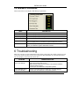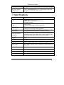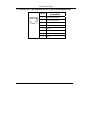
1
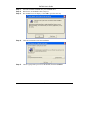
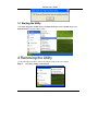
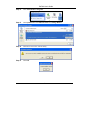
PoE-80
Eight-port Power over Ethernet Hub
User’s Guide
Version 1.06
April 2004
PoE-80 User’s Guide
Table of Contents
Copyright ............................................................................................................................................ 3
Federal Communications Commission (FCC) Interference Statement .............................................. 3
Information for Canadian Users.......................................................................................................... 4
ZyXEL Limited Warranty..................................................................................................................... 5
Syntax Conventions in this Guide ...................................................................................................... 6
Customer Support .............................................................................................................................. 6
1 About Your PoE-80.......................................................................................................................... 9
1.1 Key Features............................................................................................................................. 9
1.2 Packaging List........................................................................................................................... 9
2 Hardware and Installation.............................................................................................................. 10
2.1 Desktop Installation................................................................................................................. 10
2.2 Rack-mounted Installation ...................................................................................................... 10
2.3 Rear Panel Connections ......................................................................................................... 11
2.4 Front Panel Connections ........................................................................................................ 12
2.5 Front Panel LEDs.................................................................................................................... 12
3 Software Utility Installation ............................................................................................................ 12
3.1 Starting the Utility.................................................................................................................... 15
4 Removing the Utility....................................................................................................................... 15
5 Managing the PoE-80.................................................................................................................... 17
5.1 System Setup & Control.......................................................................................................... 17
5.2 System Information ................................................................................................................. 18
5.3 Port Specific Control ............................................................................................................... 19
5.4 Parametric Information............................................................................................................ 21
6 Troubleshooting............................................................................................................................. 21
7 Specifications ................................................................................................................................ 22
7.1 DATA OUT PoE Injector RJ-45 Port Pin Assignments........................................................... 23
2
PoE-80 User’s Guide
Copyright
Copyright © 2004 by ZyXEL Communications Corporation.
The contents of this publication may not be reproduced in any part or as a whole, transcribed, stored in a
retrieval system, translated into any language, or transmitted in any form or by any means, electronic,
mechanical, magnetic, optical, chemical, photocopying, manual, or otherwise, without the prior written
permission of ZyXEL Communications Corporation.
Published by ZyXEL Communications Corporation. All rights reserved.
Disclaimer
ZyXEL does not assume any liability arising out of the application or use of any products, or software
described herein. Neither does it convey any license under its patent rights nor the patent rights of others.
ZyXEL further reserves the right to make changes in any products described herein without notice.
This publication is subject to change without notice.
Trademarks
Trademarks mentioned in this publication are used for identification purposes only and may be properties of
their respective owners.
Federal Communications Commission (FCC)
Interference Statement
This device complies with Part 15 of FCC rules. Operation is subject to the following two conditions:
This device may not cause harmful interference.
This device must accept any interference received, including interference that may cause undesired
operations.
This equipment has been tested and found to comply with the limits for a CLASS B digital device pursuant to
Part 15 of the FCC Rules. These limits are designed to provide reasonable protection against harmful
interference in a commercial environment. This equipment generates, uses, and can radiate radio frequency
energy, and if not installed and used in accordance with the instructions, may cause harmful interference to
radio communications.
3
PoE-80 User’s Guide
If this equipment does cause harmful interference to radio/television reception, which can be determined by
turning the equipment off and on, the user is encouraged to try to correct the interference by one or more of
the following measures:
Reorient or relocate the receiving antenna.
Increase the separation between the equipment and the receiver.
Connect the equipment into an outlet on a circuit different from that to which the receiver is connected.
Consult the dealer or an experienced radio/TV technician for help.
Notice 1
Changes or modifications not expressly approved by the party responsible for compliance could void the
user's authority to operate the equipment.
Certifications
1.
2.
3.
Go to www.zyxel.com.
Select your product from the drop-down list box on the ZyXEL home page to go to that product's page.
Select the certification you wish to view from this page.
Information for Canadian Users
The Industry Canada label identifies certified equipment. This certification means that the equipment meets
certain telecommunications network protective, operation, and safety requirements. The Industry Canada
does not guarantee that the equipment will operate to a user's satisfaction.
Before installing this equipment, users should ensure that it is permissible to be connected to the facilities of
the local telecommunications company. The equipment must also be installed using an acceptable method of
connection. In some cases, the company's inside wiring associated with a single line individual service may
be extended by means of a certified connector assembly. The customer should be aware that the compliance
with the above conditions may not prevent degradation of service in some situations.
4
PoE-80 User’s Guide
Repairs to certified equipment should be made by an authorized Canadian maintenance facility designated by
the supplier. Any repairs or alterations made by the user to this equipment, or equipment malfunctions, may
give the telecommunications company cause to request the user to disconnect the equipment.
For their own protection, users should ensure that the electrical ground connections of the power utility,
telephone lines, and internal metallic water pipe system, if present, are connected together. This precaution
may be particularly important in rural areas.
Caution
Users should not attempt to make such connections themselves, but should contact the appropriate electrical
inspection authority, or electrician, as appropriate.
Note
This digital apparatus does not exceed the class A limits for radio noise emissions from digital apparatus set
out in the radio interference regulations of Industry Canada.
ZyXEL Limited Warranty
ZyXEL warrants to the original end user (purchaser) that this product is free from any defects in materials or
workmanship for a period of up to two years from the date of purchase. During the warranty period, and upon
proof of purchase, should the product have indications of failure due to faulty workmanship and/or materials,
ZyXEL will, at its discretion, repair or replace the defective products or components without charge for
either parts or labor, and to whatever extent it shall deem necessary to restore the product or components to
proper operating condition. Any replacement will consist of a new or re-manufactured functionally
equivalent product of equal value, and will be solely at the discretion of ZyXEL. This warranty shall not
apply if the product is modified, misused, tampered with, damaged by an act of God, or subjected to
abnormal working conditions.
NOTE
Repair or replacement, as provided under this warranty, is the exclusive remedy of the purchaser. This
warranty is in lieu of all other warranties, express or implied, including any implied warranty of
merchantability or fitness for a particular use or purpose. ZyXEL shall in no event be held liable for indirect
or consequential damages of any kind of character to the purchaser.
To obtain the services of this warranty, contact ZyXEL's Service Center for your Return Material
Authorization number (RMA). Products must be returned Postage Prepaid. It is recommended that the unit be
insured when shipped. Any returned products without proof of purchase or those with an out-dated warranty
will be repaired or replaced (at the discretion of ZyXEL) and the customer will be billed for parts and labor.
All repaired or replaced products will be shipped by ZyXEL to the corresponding return address, Postage
Paid. This warranty gives you specific legal rights, and you may also have other rights that vary from country
to country.
5
PoE-80 User’s Guide
Online Registration
Register your product online to receive e-mail notices of firmware upgrades and information at
www.zyxel.com for global products, or at www.us.zyxel.com for North American products.
Syntax Conventions in this Guide
The PoE-80 Eight-port Power over Ethernet Hub may be called the “PoE-80”, “the power injector” or “the
system” in this guide.
Customer Support
When you contact your customer support representative please have the following information ready:
Please have the following information ready when you contact customer support (see the next page for
contact information).
•
Product model and serial number.
•
Warranty Information.
•
Date that you received your device.
•
Brief description of the problem and the steps you took to solve it.
6
PoE-80 User’s Guide
METHOD
SUPPORT E-MAIL
SALES E-MAIL
TELEPHONE1
FAX
WEB SITE
1
REGULAR MAIL
FTP SITE
LOCATION
WORLDWIDE
[email protected]
+886-3-578-3942
www.zyxel.com
www.europe.zyxel.com
ftp.zyxel.com
[email protected]
NORTH
AMERICA
GERMANY
FRANCE
[email protected]
+886-3-578-2439
ftp.europe.zyxel.com
+1-800-255-4101
www.us.zyxel.com
+1-714-632-0882
DENMARK
NORWAY
SWEDEN
FINLAND
1
ZyXEL Communications Inc.
1130 N. Miller St.
Anaheim
CA 92806-2001
U.S.A.
[email protected]
+1-714-632-0858
ftp.us.zyxel.com
[email protected]
+49-2405-6909-0
www.zyxel.de
[email protected]
+49-2405-6909-99
ZyXEL Deutschland GmbH.
Adenauerstr. 20/A2 D-52146
Wuerselen
Germany
www.zyxel.fr
ZyXEL France
1 rue des Vergers
Bat. 1 / C
69760 Limonest
France
www.zyxel.es
ZyXEL Communications
Alejandro Villegas 33
1º, 28043 Madrid
Spain
www.zyxel.dk
ZyXEL Communications A/S
Columbusvej 5
2860 Soeborg
Denmark
www.zyxel.no
ZyXEL Communications A/S
Nils Hansens vei 13
0667 Oslo
Norway
www.zyxel.se
ZyXEL Communications A/S
Sjöporten 4, 41764 Göteborg
Sweden
www.zyxel.fi
ZyXEL Communications Oy
Malminkaari 10
00700 Helsinki
Finland
[email protected]
+33 (0)4 72 52 97 97
+33 (0)4 72 52 19 20
SPAIN
ZyXEL Communications Corp.
6 Innovation Road II
Science Park
Hsinchu 300
Taiwan
[email protected]
+34 902 195 420
[email protected]
+34 913 005 345
[email protected]
+45 39 55 07 00
[email protected]
+45 39 55 07 07
[email protected]
+47 22 80 61 80
[email protected]
+47 22 80 61 81
[email protected]
+46 31 744 7700
[email protected]
+46 31 744 7701
[email protected]
+358-9-4780-8411
[email protected]
+358-9-4780 8448
“+” is the (prefix) number you enter to make an international telephone call.
7
PoE-80 User’s Guide
1 About Your PoE-80
The PoE-80 Eight-port Power over Ethernet Hub is an eight-port power injector, designed for use
with 10/100 BaseT Ethernet networks. The PoE-80 injects DC power through the unused twistedwires (pairs 4/5 and 7/8) of a standard 8-pin CAT 5 cable. This allows increased flexibility in the
locating of power over Ethernet (PoE) enabled devices by eliminating the need for a nearby power
source.
1.1 Key Features
Eight RJ-45, 10/100 Mbps PoE-enabled ports
Ensures a constant power supply to PoE-enabled devices.
Automatically detects if connected devices are PoE-enabled to avoid sending power to nonPoE devices.
Supports power management
Control, status, and parameters manageable per port
Remote power feeding up to 100 meters
Centralized power distribution
Protection against short circuits
Accepts a wide range of AC power input
Automatically updates management information.
1.2 Packaging List
The following items come with your PoE-80.
This User’s Guide
One power cord
One console cable
One Ethernet cable
Rack mount kit
9
PoE-80 User’s Guide
2 Hardware and Installation
Do not block the device’s rear panel fans or the side panel ventilation
holes. Leave space between devices when stacking.
2.1 Desktop Installation
Step 1.
Set the PoE-80 upside-down on a sturdy level space with a power outlet nearby.
Step 2.
Make sure there is enough clearance around the PoE-80 to allow air circulation and the
attachment of cables and the power cord.
Step 3.
Remove the adhesive backing from the supplied rubber feet.
Step 4.
Attach the rubber feet to each corner on the bottom of the PoE-80. These rubber feet help
protect the PoE-80 from shock or vibration and ensure space between devices when
stacking.
Step 5.
Turn the PoE-80 right-side up after you attach the rubber feet.
2.2 Rack-mounted Installation
The PoE-80 can be mounted on an EIA standard size, 19-inch rack or in a wiring closet with other
equipment. Follow the steps below to mount your PoE-80 on a standard EIA rack using the included
rack-mounting kit.
Step 1.
Align one bracket with the holes on one side of the PoE-80 and secure it with the bracket
screws. Similarly, attach the other bracket.
10
PoE-80 User’s Guide
Step 2.
After attaching both mounting brackets, position the PoE-80 in the rack by lining up the
holes in the brackets with the appropriate holes on the rack. Secure the PoE-80 to the
rack with the rack’s mounting screws.
2.3 Rear Panel Connections
Connect the female end of the power cord to the power receptacle. Connect the male end to a 100240V AC, 50-60 Hz power source (wall outlet). Push the power switch to the ON position.
11
PoE-80 User’s Guide
2.4 Front Panel Connections
The DATA OUT ports send power and data to the PoE-enabled devices. Use Ethernet cables to
connect the eight DATA OUT RJ-45 Ethernet ports to PoE-enabled devices.
Use Ethernet cables to connect the eight DATA IN RJ-45 Ethernet ports to the LAN.
The maximum Ethernet cable length is 100m.
Use a console cable to connect the console port to a management computer.
2.5 Front Panel LEDs
The LEDs give real-time information about the system’s operational status.
COLOR
STATUS
PWR
LED
Green
PWR
FWD
Green
On
Off
On
Orange
Off
On
PWR
OFF
Off
MEANING
Power is being supplied to the PoE-80.
No power is being supplied to the PoE-80.
The DATA OUT port is connected and sending power to an
Ethernet device.
The DATA OUT port is not sending power to an Ethernet device.
The Ethernet device connected to the PoE-80’s DATA OUT port
requires more power than the PoE-80 can provide or the
Ethernet cable is shorted.
The connection to the Ethernet device is functioning properly or
no Ethernet device is connected to the DATA OUT port.
3 Software Utility Installation
Install the software utility in order to configure the PoE-80 PD. You can easily view the PoE-80’s
power parameters and control it through the software utility. The software utility provides an easyto-use GUI interface. The software utility is compatible with Windows 2000 and XP. Please follow
the below steps to install the software utility. You may need to use your Windows CD during the
installation.
12
PoE-80 User’s Guide
Step 1.
Insert the included CD-ROM into your CD-ROM drive.
Step 2.
Run (browse to and double-click) setup.exe.
Step 3.
The installation screen displays. Click OK to go to the next step.
Step 4.
Click the icon button to start the installation.
Step 5.
Choose a group name (you can use the default) and click Continue.
13
PoE-80 User’s Guide
Step 6.
Click Yes if the Version Conflict screen displays.
Step 7.
When installation finishes, click OK to finish.
14
PoE-80 User’s Guide
3.1 Starting the Utility
Click Start, Programs, ZyXEL Power over Ethernet Series and then ZyXEL Power over
Ethernet Series to run the software utility.
4 Removing the Utility
Use the following procedure to remove the software utility from your computer.
Step 1.
Click Start, Settings, Control Panel.
15
PoE-80 User’s Guide
Step 2.
Click Add or Remove Programs.
Step 3.
Click ZyXEL Power over Ethernet Series and Change/Remove.
Step 4.
Click Yes to remove the software utility.
Step 5.
Click OK.
16
PoE-80 User’s Guide
5 Managing the PoE-80
Connect to the PoE-80 through a computer connected to the console port. Then, connect a PoEenabled device to a DATA OUT port on the PoE-80. Start the utility and the management interface
displays as shown next.
The configuration changes you make in the utility are not saved when you
turn off the power to the PoE-80.
5.1 System Setup & Control
This section of the screen controls the main system level parameters setup for the PoE-80.
17
PoE-80 User’s Guide
LABEL
DESCRIPTION
Master Enable
This field enables or disables the use of the utility to control the ports. You
must enable this item to the utility to control the ports.
Calibrate System
When the PoE-80 is not functioning properly, select this check box and click
Save to Device to reset the PoE-80 to the default settings. The device
resets and the PWR FWD and PWR OFF LEDs flash.
You must disconnect all of the PoE-enabled devices
from the PoE-80 before you calibrate the system.
PD Discovery
R(ohms)
Set the upper and lower limit resistor values for the discovery of Powered
Devices (PD). The range is 19500~26500.
5.2 System Information
This section of the screen displays the hardware version, firmware version and the reset, update, port
control function buttons.
LABEL
Chip Version
DESCRIPTION
This displays the version of the PoE-80’s chipset.
18
PoE-80 User’s Guide
LABEL
DESCRIPTION
Firmware Version
This displays the PoE-80’s firmware version.
Utility Version
This displays the version of this utility.
Current Port
Serviced
This displays the port that the system’s internal state sequencer is presently
accessing.
Total Port Power
(W)
This displays the total power of the PoE-80’s ports (combined) in the
system.
Enable AutoRefresh
Select this check box to have the system automatically refresh the system
parameters (about once every two seconds).
Load from Device
Click this button to display the PoE-80’s configuration in the utility’s screen.
Save to Device
When you have made configuration changes, click this button to apply the
new configuration to the PoE-80. Configuration changes are lost when you
turn off the PoE-80 or it loses power.
5.3 Port Specific Control
This section of the screen displays port specific function controls.
LABEL
DESCRIPTION
Port Enable
Select this check box to enable the port. This function corresponds with the
master enable function.
Bypass
Classification
Select this check box to have the system skip the power classification and
directly transmit power to the PoE-enabled device.
When this check box is clear, the PoE-80 checks the current level in order
to classify the IEEE 802.3af compliant PoE-enabled device.
Bypass Detection
Select this check box to bypass the PoE-enabled device detection function.
When this check box is clear, the PoE-80 attempts to detect the 25,000Ohm resistor in an IEEE 802.3af compliant PoE-enabled device.
19
PoE-80 User’s Guide
CLASS
USAGE
POWER DEVICE POWER (W)
CLASSIFICATION CURRENT (MA)
MIN
MAX
MIN
MAX
0
Default
0.44
12.95
0
4
1
Optional
0.44
3.84
9
12
2
Optional
3.84
6.49
17
20
3
Optional
6.49
12.95
26
30
4
Optional
36
44
Reserved for future use
LABEL
LED Status
Indicators
DESCRIPTION
This is the current LED indicator display – green, red, or yellow. The LED
indicator changes depending on the status of the connected PoE-enabled
device.
Green: The PoE-enabled device is connected to the port and functioning
properly.
Red: Error, the PoE-enabled device connected to the port needs more power
than the PoE-80 can provide or the Ethernet cable has shorted.
Yellow: No PoE-enabled device is connected to the port.
Fault Status
This displays the status (Null, Overload or DR Fail) of the connected PoEenabled device that the system has detected.
Null: No PoE-enabled device is connected to the port.
Overload: The current went higher than 475mA @48V DC for more than 50
milliseconds.
DR Fail: The PoE-enabled device’s discovery resistor is not within the range
defined in IEEE 802.3af (19,600 to 26,500 Ohm).
Mode Status
This displays the status (I sample, V sample or R detect) of the connection to
a PoE-enabled device.
I sample: The PoE-80 is sending current to detect whether or not the PoEenabled device is still connected to the port.
V sample: The PoE-80 is sending voltage to detect whether or not the PoEenabled device is still connected to the port.
R detect: The PoE-80 is trying to detect the resistor of a PoE-enabled device
(the port is not connected to a PoE-enabled device).
20
PoE-80 User’s Guide
5.4 Parametric Information
This section of the screen displays individual port parameters.
LABEL
Discovery R (ohms)
DESCRIPTION
This field displays the port’s resistance value.
Port Current (mA)
This field displays the port’s current value.
Port Voltage (V):
This field displays the port’s voltage value.
Port Power (W)
This field displays the port’s watt value.
Class Current (mA)
This field displays the port’s class current value. This class current value
does not display when you enable the bypass classification function.
Determined Class
This field displays the port’s power class. The class value does not display
when you enable the bypass classification function.
6 Troubleshooting
Make sure you have securely attached the proper cables to the proper ports. Refer to the Rear Panel
Connections and Front Panel Connections sections for this information. If your PoE-80 still does
not work properly, refer to the table shown next.
PROBLEM
CORRECTIVE ACTION
No LEDs are on when I
turn on the PoE-80.
Check to see that the power cord is properly connected to the PoE-80
and an appropriate power source.
Make sure the power source is turned on and that the PoE-80 is
receiving sufficient power.
Contact your local distributor if the problem persists.
The PWR FWD LED is
not on or is blinking.
Check to see that the Ethernet cables are connected properly.
Contact your local distributor if the problem persists.
21
PoE-80 User’s Guide
PROBLEM
Power is not being
supplied to my PoEenabled devices.
CORRECTIVE ACTION
Ensure that the Ethernet cables connecting the PoE-enabled devices
to the PoE-80’s DATA OUT ports are securely attached. Make sure
the PoE-80 is connected to a power source.
7 Specifications
Standards
IEEE 802.3af
Ports
8 DATA IN RJ-45 Ethernet ports
8 DATA OUT PoE injector RJ-45 Ethernet ports
1 RS-232 console port
LEDs
System: Power
Per Port (2 LEDs): Power Forwarding, Power Off
Power Output
-48V DC, 100 Watts maximum
Current (per port maximum): 350mA @ 48V DC
Management
Microsoft Windows-based application for power management
Power Management
Functions
Current ports serviced list, system total serviced power budget, power
port disable/ enable, power support priority, power overload auto shut
down, power port operation status, power consumption limit
Weight
2.7 kg
Cooling
2 DC fans
Dimensions
440(W) x 224(D) x 44(H) mm (19” in width rack mountable)
Power Supply
100 - 240V AC, 50/60Hz internal universal power supply with fuse and
power switch
Power Consumption
130 Watts maximum
Operating Temperature
0 – 45 degrees Celsius (32 – 104 degrees Fahrenheit)
Operational Humidity
10% to 95% (Non-condensing)
EMI and Safety
FCC Class A, CE, UL, cUL
22
PoE-80 User’s Guide
7.1 DATA OUT PoE Injector RJ-45 Port Pin Assignments
PIN NO
RJ-45 SIGNAL
ASSIGNMENT
1
Output Transmit Data +
2
Output Transmit Data -
3
Receive Data +
4
Power +
5
Power +
6
Receive Data -
7
Power -
8
Power -
1 2 3 4 5 6 7 8
23