1
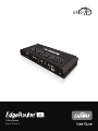
3-Port Router
Model: ERLite-3
EdgeRouter™ Lite User Guide
Table of Contents
Table of Contents
Chapter 1: Overview. . . . . . . . . . . . . . . . . . . . . . . . . . . . . . . . . . . . . . . . . . . . . . . . 1
Introduction. . . . . . . . . . . . . . . . . . . . . . . . . . . . . . . . . . . . . . . . . . . . . . . . . . . . . . . . . . . . . . . . . . . . . . 1
Package Contents. . . . . . . . . . . . . . . . . . . . . . . . . . . . . . . . . . . . . . . . . . . . . . . . . . . . . . . . . . . . . . . . 1
Configuration Interface System Requirements. . . . . . . . . . . . . . . . . . . . . . . . . . . . . . . . . . . . . 1
Hardware Overview . . . . . . . . . . . . . . . . . . . . . . . . . . . . . . . . . . . . . . . . . . . . . . . . . . . . . . . . . . . . . . 1
Chapter 2: Installation. . . . . . . . . . . . . . . . . . . . . . . . . . . . . . . . . . . . . . . . . . . . . . 2
Introduction. . . . . . . . . . . . . . . . . . . . . . . . . . . . . . . . . . . . . . . . . . . . . . . . . . . . . . . . . . . . . . . . . . . . . . 2
Installation of the EdgeRouter Lite. . . . . . . . . . . . . . . . . . . . . . . . . . . . . . . . . . . . . . . . . . . . . . . . 2
Typical Deployment Scenarios. . . . . . . . . . . . . . . . . . . . . . . . . . . . . . . . . . . . . . . . . . . . . . . . . . . . 3
Chapter 3: Using EdgeOS. . . . . . . . . . . . . . . . . . . . . . . . . . . . . . . . . . . . . . . . . . . 5
Ports and Status Information. . . . . . . . . . . . . . . . . . . . . . . . . . . . . . . . . . . . . . . . . . . . . . . . . . . . . . 5
Navigation. . . . . . . . . . . . . . . . . . . . . . . . . . . . . . . . . . . . . . . . . . . . . . . . . . . . . . . . . . . . . . . . . . . . . . . 5
Common Interface Options. . . . . . . . . . . . . . . . . . . . . . . . . . . . . . . . . . . . . . . . . . . . . . . . . . . . . . . 6
Chapter 4: Dashboard Tab. . . . . . . . . . . . . . . . . . . . . . . . . . . . . . . . . . . . . . . . . 10
Services. . . . . . . . . . . . . . . . . . . . . . . . . . . . . . . . . . . . . . . . . . . . . . . . . . . . . . . . . . . . . . . . . . . . . . . . . 10
Interfaces . . . . . . . . . . . . . . . . . . . . . . . . . . . . . . . . . . . . . . . . . . . . . . . . . . . . . . . . . . . . . . . . . . . . . . . 11
Chapter 5: Routing Tab . . . . . . . . . . . . . . . . . . . . . . . . . . . . . . . . . . . . . . . . . . . . 13
IPv6 Routing . . . . . . . . . . . . . . . . . . . . . . . . . . . . . . . . . . . . . . . . . . . . . . . . . . . . . . . . . . . . . . . . . . . . 13
Routes. . . . . . . . . . . . . . . . . . . . . . . . . . . . . . . . . . . . . . . . . . . . . . . . . . . . . . . . . . . . . . . . . . . . . . . . . . 14
OSPF. . . . . . . . . . . . . . . . . . . . . . . . . . . . . . . . . . . . . . . . . . . . . . . . . . . . . . . . . . . . . . . . . . . . . . . . . . . . 16
Chapter 6: Security Tab. . . . . . . . . . . . . . . . . . . . . . . . . . . . . . . . . . . . . . . . . . . . 19
Firewall Policies . . . . . . . . . . . . . . . . . . . . . . . . . . . . . . . . . . . . . . . . . . . . . . . . . . . . . . . . . . . . . . . . . 19
Firewall Groups. . . . . . . . . . . . . . . . . . . . . . . . . . . . . . . . . . . . . . . . . . . . . . . . . . . . . . . . . . . . . . . . . . 23
NAT. . . . . . . . . . . . . . . . . . . . . . . . . . . . . . . . . . . . . . . . . . . . . . . . . . . . . . . . . . . . . . . . . . . . . . . . . . . . . 24
VPN. . . . . . . . . . . . . . . . . . . . . . . . . . . . . . . . . . . . . . . . . . . . . . . . . . . . . . . . . . . . . . . . . . . . . . . . . . . . . 27
Chapter 7: Services Tab . . . . . . . . . . . . . . . . . . . . . . . . . . . . . . . . . . . . . . . . . . . 28
DHCP Server . . . . . . . . . . . . . . . . . . . . . . . . . . . . . . . . . . . . . . . . . . . . . . . . . . . . . . . . . . . . . . . . . . . . 28
DNS. . . . . . . . . . . . . . . . . . . . . . . . . . . . . . . . . . . . . . . . . . . . . . . . . . . . . . . . . . . . . . . . . . . . . . . . . . . . . 31
PPPoE. . . . . . . . . . . . . . . . . . . . . . . . . . . . . . . . . . . . . . . . . . . . . . . . . . . . . . . . . . . . . . . . . . . . . . . . . . . 32
Chapter 8: Users Tab . . . . . . . . . . . . . . . . . . . . . . . . . . . . . . . . . . . . . . . . . . . . . . 33
Local. . . . . . . . . . . . . . . . . . . . . . . . . . . . . . . . . . . . . . . . . . . . . . . . . . . . . . . . . . . . . . . . . . . . . . . . . . . . 33
Remote . . . . . . . . . . . . . . . . . . . . . . . . . . . . . . . . . . . . . . . . . . . . . . . . . . . . . . . . . . . . . . . . . . . . . . . . . 34
Ubiquiti Networks, Inc.
i
EdgeRouter™ Lite User Guide
Table of Contents
Chapter 9: Toolbox. . . . . . . . . . . . . . . . . . . . . . . . . . . . . . . . . . . . . . . . . . . . . . . . 35
Ping. . . . . . . . . . . . . . . . . . . . . . . . . . . . . . . . . . . . . . . . . . . . . . . . . . . . . . . . . . . . . . . . . . . . . . . . . . . . . 35
Trace. . . . . . . . . . . . . . . . . . . . . . . . . . . . . . . . . . . . . . . . . . . . . . . . . . . . . . . . . . . . . . . . . . . . . . . . . . . . 36
Discover. . . . . . . . . . . . . . . . . . . . . . . . . . . . . . . . . . . . . . . . . . . . . . . . . . . . . . . . . . . . . . . . . . . . . . . . .36
Packet Capture. . . . . . . . . . . . . . . . . . . . . . . . . . . . . . . . . . . . . . . . . . . . . . . . . . . . . . . . . . . . . . . . . . 36
Log Monitor. . . . . . . . . . . . . . . . . . . . . . . . . . . . . . . . . . . . . . . . . . . . . . . . . . . . . . . . . . . . . . . . . . . . . 37
Appendix A: Command Line Interface. . . . . . . . . . . . . . . . . . . . . . . . . . . . . 38
Overview. . . . . . . . . . . . . . . . . . . . . . . . . . . . . . . . . . . . . . . . . . . . . . . . . . . . . . . . . . . . . . . . . . . . . . . . 38
Access the CLI. . . . . . . . . . . . . . . . . . . . . . . . . . . . . . . . . . . . . . . . . . . . . . . . . . . . . . . . . . . . . . . . . . . 38
CLI Modes. . . . . . . . . . . . . . . . . . . . . . . . . . . . . . . . . . . . . . . . . . . . . . . . . . . . . . . . . . . . . . . . . . . . . . . 40
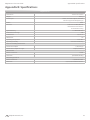
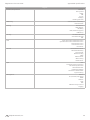
Appendix B: Specifications. . . . . . . . . . . . . . . . . . . . . . . . . . . . . . . . . . . . . . . . 47
Appendix C: Safety Notices. . . . . . . . . . . . . . . . . . . . . . . . . . . . . . . . . . . . . . . . 49
Electrical Safety Information. . . . . . . . . . . . . . . . . . . . . . . . . . . . . . . . . . . . . . . . . . . . . . . . . . . . . 49
Appendix D: Warranty. . . . . . . . . . . . . . . . . . . . . . . . . . . . . . . . . . . . . . . . . . . . . 50
General Warranty. . . . . . . . . . . . . . . . . . . . . . . . . . . . . . . . . . . . . . . . . . . . . . . . . . . . . . . . . . . . . . . . 50
Appendix E: Compliance Information. . . . . . . . . . . . . . . . . . . . . . . . . . . . . . 51
FCC. . . . . . . . . . . . . . . . . . . . . . . . . . . . . . . . . . . . . . . . . . . . . . . . . . . . . . . . . . . . . . . . . . . . . . . . . . . . . 51
Industry Canada. . . . . . . . . . . . . . . . . . . . . . . . . . . . . . . . . . . . . . . . . . . . . . . . . . . . . . . . . . . . . . . . . 51
Australia and New Zealand . . . . . . . . . . . . . . . . . . . . . . . . . . . . . . . . . . . . . . . . . . . . . . . . . . . . . . 51
Japan VCCI-A. . . . . . . . . . . . . . . . . . . . . . . . . . . . . . . . . . . . . . . . . . . . . . . . . . . . . . . . . . . . . . . . . . . . 51
CE Marking. . . . . . . . . . . . . . . . . . . . . . . . . . . . . . . . . . . . . . . . . . . . . . . . . . . . . . . . . . . . . . . . . . . . . . 51
RoHS/WEEE Compliance Statement. . . . . . . . . . . . . . . . . . . . . . . . . . . . . . . . . . . . . . . . . . . . . . 51
Appendix F: Declaration of Conformity . . . . . . . . . . . . . . . . . . . . . . . . . . . . 53
Appendix G: Contact Information. . . . . . . . . . . . . . . . . . . . . . . . . . . . . . . . . . 54
Ubiquiti Networks Support. . . . . . . . . . . . . . . . . . . . . . . . . . . . . . . . . . . . . . . . . . . . . . . . . . . . . . 54
Ubiquiti Networks, Inc.
ii
EdgeRouter™ Lite User Guide
Chapter 1: Overview
Chapter 1: Overview
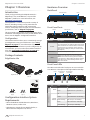
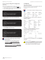
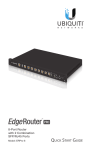
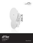
Hardware Overview
Back Panel
Introduction
Power
Ventilation Holes
Thank you for purchasing the Ubiquiti Networks ™
EdgeRouter™ Lite, model ERLite-3. It is part of the
EdgeMAX™ platform. For more information, visit
www.ubnt.com/edgemax
The EdgeRouter is a router that provides a variety of
features, including routing, security, Virtual Private
Networking (VPN), monitoring and management
services, and Quality of Service (QoS). For more detailed
specifications, refer to “EdgeOS” on page 48.
12V DC
GROUND
Grounding Hole with
Grounding Screw
Front Panel Ports
Console
This User Guide is designed to provide instructions about
installation of the EdgeRouter and to provide details about
how to use the EdgeOS™ Configuration Interface.
Ethernet (0-2)
Reset
SPEED
CONSOLE
0
1
2
Configuration
The intuitive interface allows you to conveniently manage
your EdgeRouter using your web browser. (See “Using
EdgeOS” on page 5 for more information.) If you need
to configure advanced features or prefer configuration by
command line, you can use the Command Line Interface
(CLI). (See “Command Line Interface” on page 38 for
more information.)
Interface
Description
Console
Ethernet (0-2)
10/100/1000 Mbps Ethernet ports.
To reset to factory defaults, disconnect the Power
Adapter from the Power port. Press and hold the
Reset button while connecting the Power Adapter
to the Power port. Keep holding the button until the
right LED on port 2 starts flashing and then stops
after a few seconds.
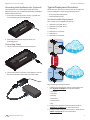
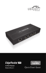
Package Contents
EdgeRouter Lite
RJ45 serial console port for Command Line Interface
(CLI) management. Use a RJ45-to-DB9, serial console
cable, also known as a rollover cable, to connect the
Console port to your computer. (If your computer
does not have a DB9 port, then you will also need a
DB9 adapter.)
Reset
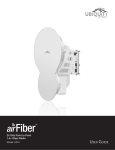
Front Panel LEDs
The LEDs on the left side of each port are not used at this
time. Below is a description of the right LED functionality:
Power
EdgeRouter Lite
Power Adapter
(12V, 1A)
Speed/Link/Act
1000 Mbps
Power Cord
SPEED
CONSOLE
3-Port Router
Model: ERLite-3
Configuration Interface System
Requirements
• Microsoft Windows XP, Windows Vista, Windows 7,
Windows 8, Linux, or Mac OS X
0
1
2
State
Status
Off
EdgeRouter Lite not powered on.
Green
EdgeRouter Lite is powered on.
Off
No Link
Amber
Link Established at 10/100 Mbps
Amber Flashing
Link Activity at 10/100 Mbps
Green
Link Established at 1000 Mbps
Green Flashing
Link Activity at 1000 Mbps
Power
Quick Start Guide
Ethernet (0-2)
M2.9 Anchors
(Qty. 2)
Console
LED
M2.9x20 Screws
(Qty. 2)
Speed/Link/Act
10/100 Mbps
Speed/
Link/Act
• Web Browser: Google Chrome, Mozilla Firefox, or
Microsoft Internet Explorer 8 (or above)
Ubiquiti Networks, Inc.
1
EdgeRouter™ Lite User Guide
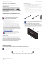
Chapter 2: Installation
Chapter 2: Installation
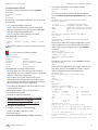
Wall-Mounting
To mount the EdgeRouter Lite on a wall you will need a
drill, a 6 mm drill bit, and a Phillips screwdriver.
Introduction
1. Use a 6 mm drill bit to drill two holes 100 mm apart.
(You can use the template at the bottom of the page to
mark the holes.)
This chapter covers the installation instructions and a
couple of typical deployment scenarios (see “Typical
Deployment Scenarios” on page 3). After you
install the EdgeRouter, refer to the instructions in “Using
EdgeOS” on page 5, which explain how to access the
Configuration Interface.
2. Insert the M2.9 Anchors into the holes. Use a Phillips
screwdriver to secure a M2.9x20 Screw to each anchor.
Leave a clearance of approximately 3 mm between
each screw head and its anchor.
Installation of the EdgeRouter Lite
Mount the EdgeRouter on a wall, or place it on a
bench top.
Note: Keep 20 mm of clearance next to the
ventilation holes for adequate airflow.
3 mm
Cabling Requirements
• For indoor applications, use Category 5 (or above)
cabling approved for indoor use.
Note: You can also mount the EdgeRouter Lite in a
vertical orientation.
• For outdoor applications, shielded Category 5 (or
above) cabling should be used for all wired Ethernet
connections and should be grounded through the
AC ground of the power supply. We recommend that
you protect your outdoor networks from the most
brutal environments and devastating ESD attacks with
industrial‑grade shielded Ethernet cable from Ubiquiti
Networks™. For more details, visit:
www.ubnt.com/toughcable
12
V
DC
GR
OU
ND
3. Position the EdgeRouter Lite with the Ethernet
ports facing down. Place the Wall-Mount Slots of the
EdgeRouter Lite over the screw heads on the wall. Then
slide the EdgeRouter Lite down to lock it into place.
Note: Although the cabling can be located
outdoors, the EdgeRouter Lite itself should be
housed inside a protective enclosure.
Terms of Use
All Ethernet cabling runs must use CAT5 (or above). It
is the customer’s responsibility to follow local country
regulations, including operation within legal frequency
channels, output power, indoor cabling requirements, and
Dynamic Frequency Selection (DFS) requirements.
Mounting Template
The recommended mounting orientation is horizontal with the ports facing down.
Note: The EdgeRouter Lite can also be mounted in a vertical orientation. Turn this page sideways to mark the holes for
vertical placement.
100 mm
Ubiquiti Networks, Inc.
2
EdgeRouter™ Lite User Guide
Chapter 2: Installation
Grounding the EdgeRouter Lite (Optional)
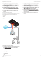
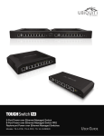
Typical Deployment Scenarios
The EdgeRouter Lite is grounded through the Power
Adapter; however, you can add optional ESD grounding for
enhanced ESD protection.
While there are numerous scenarios that are possible, this
section highlights a couple of typical deployments:
1. Loosen the Grounding Screw to secure a ground wire
(not included) to the Grounding Hole.
• Corporate Deployment
• Service Provider Deployment
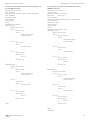
Service Provider Deployment
This scenario uses six EdgeRouter devices:
1. OSPF Area 0 to OSPF Area 1
V DC
12
2. OSPF Area 0 to OSPF Area 2
ND
OU
GR
3. OSPF Area 1
4. OSPF Area 1 to Internet
5. OSPF Area 2
6. OSPF Area 2 to Internet
2. Secure the other end of the ground wire to a
grounding block.
Connecting Power
1. Connect the Power Adapter to the Power port.
Site A
OSPF
Area 1
Internet
C
VD
12
ND
OU
GR
Site-to-Site
Link
OSPF
Area 0
2. Connect the Power Cord to the Power Adapter. Connect
the other end of the Power Cord to a power outlet.
Site B
OSPF
Area 2
Internet
Here are the typical steps to follow:
1. Configure the appropriate settings on the System tab
(see “System” on page 6 for more information):
•Host Name
•Time Zone
•Gateway
•Name Server
•Domain Name
•NTP
2. Configure the interfaces on the Dashboard tab; see
“Interfaces” on page 11 for more information.
3. Configure OSPF settings on the Routing > OSPF tab; see
“OSPF” on page 16 for more information.
Ubiquiti Networks, Inc.
3
EdgeRouter™ Lite User Guide
Chapter 2: Installation
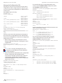
4. Configure DHCP server(s) on the Services tab; see
”DHCP Server” on page 28 for more information.
2. Configure the interfaces on the Dashboard tab; see
“Interfaces” on page 11 for more information.
5. Configure NAT rules on the Security > NAT tab; see
”NAT” on page 24 for more information.
3. Configure DHCP server(s) on the Services tab; see
”DHCP Server” on page 28 for more information.
6. Configure firewall rules on the Security > Firewall
Policies tab; see ”Firewall Policies” on page 19 for
more information.
4. Configure NAT rules on the Security > NAT tab; see
”NAT” on page 24 for more information.
7. Configure additional settings as needed for your
network.
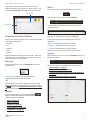
Corporate Deployment
This scenario uses a single EdgeRouter device. The three
independent interfaces connect to the following:
5. Configure firewall rules on the Security > Firewall
Policies tab; see ”Firewall Policies” on page 19 for
more information.
6. Configure additional settings as needed for your
network.
• Internet
• DMZ
• LAN
Firewall Policies
Internet
DMZ
LAN
Here are the typical steps to follow:
1. Configure the appropriate settings on the System tab
(see “System” on page 6 for more information):
•Host Name
•Time Zone
•Gateway
•Name Server
•Domain Name
•NTP
Ubiquiti Networks, Inc.
4
EdgeRouter™ Lite User Guide
Chapter 3: Using EdgeOS
EdgeOS is a powerful, sophisticated operating system that
manages your EdgeRouter. It offers both a browser‑based
interface (EdgeOS Configuration Interface) for easy
configuration and a Command Line Interface (CLI) for
advanced configuration.
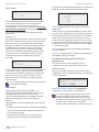
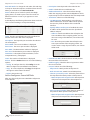
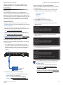
To access the EdgeOS Configuration Interface:
1. Connect an Ethernet cable from the Ethernet port
of your computer to the port labeled 0 on the
EdgeRouter.
Chapter 3: Using EdgeOS
Note: To enhance security, we recommend that you
change the default login using at least one of the
following options:
• Set up a new user account on the Users > Local tab
(preferred option). For details, go to “Add User”
on page 33.
• Change the default password of the ubnt login on
the Users > Local tab. For details, go to “Configure
the User” on page 34.
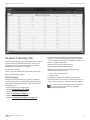
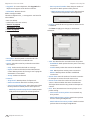
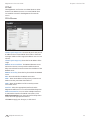
Ports and Status Information
The Ports image displays the active connections. An amber
port indicates 10/100 Mbps, and a green port indicates
1000 Mbps. The Status bar graphs display the following:
CPU The percentage of processing power that the
EdgeRouter is using is displayed.
RAM The percentage of RAM that the EdgeRouter is using
is displayed.
Uptime The duration of the EdgeRouter’s activity is
displayed.
2. Configure the Ethernet adapter on your computer
with a static IP address on the 192.168.1.x subnet (e.g.,
192.168.1.100).
Note: As an alternative, you can connect a serial
cable to the Console port of the EdgeRouter. See
“Command Line Interface” on page 38 for
more information.
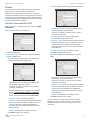
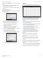
3. Launch your web browser. Type https://192.168.1.1 in
the address field. Press enter (PC) or return (Mac).
4. The login screen will appear. Enter ubnt in the
Username and Password fields. Read the Ubiquiti
License Agreement, and check the box next to I agree
to the terms of this License Agreement to accept it. Click
Login.
Place your mouse over a port to view the following:
Enabled/Disabled The administrative status is displayed.
Link The connection status is displayed.
Speed The speed (in Mbps) and duplex mode are
displayed.
Navigation
The EdgeOS software consists of five primary tabs, and
some of these tabs have sub-tabs. This User Guide covers
each tab with a chapter. For details on a specific tab, refer
to the appropriate chapter.
• Dashboard The “Dashboard Tab” on page 10
displays status information about services and
interfaces. You can also configure interfaces and Virtual
Local Area Networks (VLANs).
• Routing The “Routing Tab” on page 13 configures
static routes and Open Shortest Path First (OSPF)
settings, including metrics, areas, and interfaces.
• Security The “Security Tab” on page 19 configures
firewall policies, firewall groups, Network Address
Translation (NAT) rules, and PPTP VPN options.
• Services The “Services Tab” on page 28 configures
DHCP servers, DNS forwarding, and the PPPoE server.
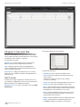
The EdgeOS Configuration Interface will appear, allowing
you to customize your settings as needed.
Ubiquiti Networks, Inc.
• Users The “Users Tab” on page 33 configures user
accounts with administrator or operator access.
5
EdgeRouter™ Lite User Guide
Chapter 3: Using EdgeOS
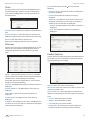
Depending on the tab you click, some of the screens
display information and options in multiple sections. You
can click the open/close tab to hide or display a section.
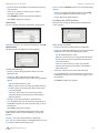
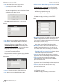
Alerts
The number of new alerts is displayed in a red popup.
Open/Close Tab
At the bottom of the screen, click the Alerts tab.
Open/Close Tab
A table displays the following information about each
important event.
Common Interface Options
Message A description of the event is displayed.
The common interface options are accessible from all tabs
on the EdgeOS interface:
Field The settings that are affected by the event are
displayed.
• Welcome
Actions The following options are available:
• CLI
• Remove Click this button to clear an alert.
• Toolbox
• Clear All Click this button to clear all alerts.
• Alerts
Click the top right corner of the Alerts tab to close it.
• System
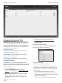
System
Required fields are marked by a blue asterisk *. When the
information icon is displayed, you can click the icon for
more information about an option.
At the bottom of the screen, click the System tab to access
the device settings.
Welcome
At the top left of the screen, click Welcome to view the
Logout option:
The device settings are organized into these sections:
• “Basic Settings” on page 7
• “Management Settings” on page 7
• “Configuration Management & Device Maintenance”
on page 8
Logout To manually log out of the EdgeRouter
Configuration Interface, click this option.
• “Restart & Shut Down Router” on page 9
CLI
Advanced users can make configuration changes using
Linux commands. At the top right of the screen, click the
CLI
button. See “Command Line Interface” on page
38 for more information.
Toolbox
At the top right of the screen, click the Toolbox
button. The following network administration and
monitoring tools are available:
• “Ping” on page 35
• “Trace” on page 36
• “Discover” on page 36
• “Packet Capture” on page 36
• “Log Monitor” on page 37
Ubiquiti Networks, Inc.
6
EdgeRouter™ Lite User Guide
Basic Settings
Chapter 3: Using EdgeOS
Domain Name
Host Name
System host name Enter a name for the EdgeRouter. The
host name identifies the EdgeRouter as a specific device.
For example, a .com URL typically uses this format:
<host_name>.domain_name.com
Time Zone
System domain name Enter the domain name of your
EdgeRouter. The domain name identifies the EdgeRouter’s
network on the Internet. For example, a .com URL typically
uses this format:
host_name.<domain_name>.com
NTP
NTP is a protocol for synchronizing the clocks of computer
systems over packet-switched, variable-latency data
networks. You can use it to set the system time on the
EdgeRouter. If the System Log option is enabled, then
the system time is reported next to every log entry that
registers a system event.
Use Coordinated Universal Time (UTC) UTC is the
international time standard used by Network Time
Protocol (NTP) servers. If your routers are located in
multiple time zones, then you may want to use UTC.
Time zone To set your network to a specific time zone,
select Time zone and configure the following:
• Select continent/ocean Select your location.
Automatically update system time using NTP By
default, the EdgeRouter obtains the system time from a
time server on the Internet.
• Select country/region Select your location.
Click Save to apply your changes.
• Select time zone Select your time zone.
Management Settings
Gateway
SSH Server
System gateway address Enter the IP address of your
gateway. This will set up your default route. If you want to
set up additional default routes, configure them as static
routes on the Routing tab. See “Routing Tab” on page
13 for more information.
Name Server
Domain Name System (DNS) translates domain names to
IP addresses; each DNS server on the Internet holds these
mappings in its respective DNS database.
Enable Enabled by default. This option allows SSH
(Secure Shell) access to the EdgeRouter for remote
configuration by command line. SSH uses encryption and
authentication, so it is a secure form of communication.
See “Command Line Interface” on page 38 for more
information.
Port Specify the TCP/IP port of the SSH server. The default
is 22.
System name server Enter the IP address of your DNS
server (example: 192.0.2.1 for IPv4 or 2001:db8::1 for IPv6).
Click Add New to add additional servers.
Ubiquiti Networks, Inc.
7
EdgeRouter™ Lite User Guide
Telnet Server
Enable Disabled by default. This option allows Telnet
access to the EdgeRouter for remote configuration
by command line. Telnet is not a secure form of
communication, so we recommend SSH. See “Command
Line Interface” on page 38 for more information.
Port Specify the TCP/IP port of the Telnet server. The
default is 23.
System Log
Every logged message contains at least a system time and
host name. Usually a specific service name that generates
the system event is also specified within the message.
Messages from different services have different contexts
and different levels of detail. Usually error, warning, or
informational system service messages are reported;
however, more detailed debug level messages can also
be reported. The more detailed the system messages
reported, the greater the volume of log messages
generated.
Chapter 3: Using EdgeOS
For the purpose of equipment identification, configure the
SNMP agent with contact and location information:
Enable Disabled by default. This option activates the
SNMP agent.
SNMP community Specify the SNMP community string.
It is required to authenticate access to MIB (Management
Information Base) objects and functions as an embedded
password. The device supports a read-only community
string; authorized management stations have read access
to all the objects in the MIB except the community strings,
but do not have write access. The device supports SNMP
v1. The default is public.
Contact Specify the contact who should be notified in
case of emergency.
Location Specify the physical location of the EdgeRouter.
Click Save to apply your changes.
Configuration Management & Device
Maintenance
The controls in this section manage the device
configuration routines and firmware maintenance.
Log to remote server This option allows the EdgeRouter
to send system log messages to a remote server. Enter
the remote host IP address and TCP/IP port that should
receive the system log (syslog) messages. 514 is the
default port for the commonly used, system message
logging utilities.
Back Up Config
We recommend that you back up your current system
configuration before updating the firmware or uploading
a new configuration.
Note: Properly configure the remote host to receive
syslog protocol messages.
SNMP Agent
Simple Network Monitor Protocol (SNMP) is an
application layer protocol that facilitates the exchange
of management information between network
devices. Network administrators use SNMP to monitor
network‑attached devices for issues that warrant
attention.
The EdgeRouter contains an SNMP agent, which does the
following:
Download backup config file Click Download to
download the current system configuration file.
Note: We strongly recommend that you save the
configuration file in a secure location because it
includes confidential information. The user login
passwords are encrypted; however, other passwords
and keys (such as those used for VPN, BGP,
authentication, and RADIUS) are stored in plain text.
• Provides an interface for device monitoring using SNMP
• Communicates with SNMP management applications
for network provisioning
• Allows network administrators to monitor network
performance and troubleshoot network problems
Ubiquiti Networks, Inc.
8
EdgeRouter™ Lite User Guide
Restore Config
Upload config file Click Upload a file to locate the
new configuration file. Select the file and click Choose.
We recommend that you back up your current system
configuration before uploading the new configuration.
Upgrade System Image
Download the firmware file from downloads.ubnt.com
and save it on your computer.
Chapter 3: Using EdgeOS
Shut Down Router
Shut Down To turn off the EdgeRouter, click this option.
WARNING: Click Shut Down to properly shut down
the EdgeRouter. An improper shutdown, such
as disconnecting the EdgeRouter from its power
supply, runs the risk of data corruption!
Click the top right corner of the System tab to close it.
The firmware update is compatible with all configuration
settings. The system configuration is preserved while
the EdgeRouter is updated with a new firmware version.
However, we recommend that you back up your current
system configuration before updating the firmware.
Upload system image To update the EdgeRouter with
new firmware, click Upload a file and locate the new
firmware file. Then click Choose.
Please be patient, as the firmware update routine can take
three to seven minutes. You cannot access the EdgeRouter
until the firmware update routine is completed.
WARNING: Do not power off, do not reboot, and
do not disconnect the EdgeRouter from the power
supply during the firmware update process as these
actions will damage the EdgeRouter!
Restart & Shut Down Router
Restart Router
Restart To turn the EdgeRouter off and back on again,
click this option.
Ubiquiti Networks, Inc.
9
EdgeRouter™ Lite User Guide
Chapter 4: Dashboard Tab
Chapter 4: Dashboard Tab
Routes
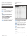
The Dashboard tab displays status information about
services and interfaces. You can also configure interfaces
and Virtual Local Area Networks (VLANs). Any setting
marked with a blue asterisk * is required.
• Connected
The following route types are listed:
• Static
• RIP (Routing Information Protocol)
Services
• OSPF (Open Shortest Path First)
Status information is displayed. Each heading is a
convenient link to the appropriate tab.
• IBGP (Interior Border Gateway Protocol)
• EBGP (Exterior Border Gateway Protocol)
The number of each route type and the total number of
routes are displayed. Click Routes to display the Routing
> Routes tab. Go to “Routes” on page 14 for more
information.
OSPF
The OSPF status, settings, and number of areas are
displayed. Click OSPF to display the Routing > OSPF tab.
Go to “OSPF” on page 16 for more information.
NAT
The NAT (Network Address Translation) status and number
of NAT rules are displayed. Click NAT to display the
Security > NAT tab. Go to “NAT” on page 24 for more
information.
Firewall
The firewall status and numbers of sets and rules are
displayed. Click Firewall to display the Security > Firewall
Policies tab. Go to “Firewall Policies” on page 19 for
more information.
Ubiquiti Networks, Inc.
10
EdgeRouter™ Lite User Guide
Chapter 4: Dashboard Tab
DHCP
All/Ethernet/VLAN
The DHCP server status and numbers of active and
inactive servers are displayed. Click DHCP to display the
Services tab. Go to “DHCP Server” on page 28 for more
information.
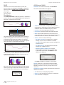
Add VLAN To create a new VLAN, click Add VLAN.
The Create a New VLAN screen appears.
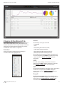
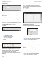
Interfaces
Distribution
Click Hide Distribution to hide the Interfaces > Distribution
section. Click the remaining open/close tab to display the
Interfaces > Distribution section again.
Open/Close Tab
• VLAN ID The VLAN ID is a unique value assigned to
each VLAN at a single device; every VLAN ID represents
a different VLAN. The VLAN ID range is 2 to 4094.
• Interface Select the appropriate interface.
• Description Enter keywords to describe this VLAN.
The RX Rate and TX Rate graph displays the current data
traffic in both graphical and numerical form. The graph
scale and throughput dimension (Mbps, for example)
change dynamically depending on the mean throughput
value. The statistics are updated automatically.
• MTU Enter the MTU (Maximum Transmission Unit)
value, which is the maximum packet size (in bytes) that a
network interface can transmit. The default is 1500.
• Address Select one of the following:
-- No address settings The VLAN uses no address
settings. (In most cases, an address is needed.)
-- Use DHCP The VLAN acquires network settings from
a DHCPv4 server.
-- Use DHCP for IPv6 The VLAN acquires network
settings from a DHCPv6 server.
The RX and TX pie charts display the data traffic allocated
among the ports of the EdgeRouter. The pie charts are
updated automatically.
-- Manually define IP address(es) Enter the
static IP address (example: 192.0.2.1/24 for IPv4
or 2001:db8::1/32 for IPv6). Click Add IP to enter
additional IP addresses.
Click Save to apply your changes, or click Cancel.
Place your mouse over a port’s portion of the pie chart to
view its percentage of data traffic allocation, TX (amount
of transmitted data), and RX (amount of received data).
Search Allows you to search for specific text. Begin
typing; there is no need to press enter. The results are
filtered in real time as soon as you type two or more
characters.
All/Ethernet/VLAN Click the appropriate tab to filter the
interfaces as needed.
• All All interfaces are displayed by default.
• Ethernet All of the Ethernet interfaces are displayed.
• VLAN All VLANs are displayed.
Ubiquiti Networks, Inc.
11
EdgeRouter™ Lite User Guide
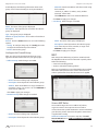
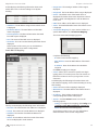
A table displays the following information about each
interface. Click a column heading to sort by that heading.
Chapter 4: Dashboard Tab
• Address Select one of the following:
-- No address settings The interface uses no address
settings. (In most cases, an address is needed.)
-- Use DHCP The interface acquires network settings
from a DHCPv4 server. Click the Renew button to
acquire fresh network settings.
Description The keywords you entered to describe the
interface are displayed.
Interface The name of the interface is displayed.
Type The type of interface is displayed.
IP Addr The IP address of the interface is displayed.
MTU The MTU (Maximum Transmission Unit) value of the
interface is displayed. This is the maximum packet size (in
bytes) that the interface can transmit.
-- Use DHCP for IPv6 The interface acquires network
settings from a DHCPv6 server.
-- Manually define IP address(es) Enter the
static IP address (example: 192.0.2.1/24 for IPv4
or 2001:db8::1/32 for IPv6). Click Add IP to enter
additional IP addresses.
TX The transmit speed of the interface is displayed.
RX The receive speed of the interface is displayed.
Status The connection status of the interface is displayed.
Actions Click the Actions button to access the following
options:
• Config To configure the interface, click Config. Go to
the Configure the Interface section.
• Disable Disable the interface while keeping its
configuration.
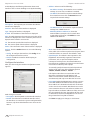
Configure the Interface
After you click Config, the Interface Configuration screen
appears.
• MTU Enter the MTU (Maximum Transmission Unit)
value, which is the maximum packet size (in bytes) that a
network interface can transmit. The default is 1500.
• Speed/Duplex The default is Auto negotiation. The
EdgeRouter automatically negotiates transmission
parameters, such as speed and duplex, with its
counterpart. In this process, the networked devices
first share their capabilities and then choose the fastest
transmission mode they both supoprt.
To manually specify the transmission link speed and
duplex mode, select one of the following options:
100/full, 100/half, 10/full, or 10/half.
Full-duplex mode allows communication in both
directions simultaneously. Half-duplex mode
allows communication in both directions, but not
simultaneously and only in one direction at a time.
Make changes as needed.
• Description Enter keywords to describe this interface.
• Enable Check the box to enable the interface. All of
the interfaces are saved in the system configuration file;
however, only the enabled interfaces are active on the
device.
Ubiquiti Networks, Inc.
• Proxy ARP Enable the EdgeRouter to answer a source
host’s ARP (Address Resolution Protocol) requests for
the IP address of a destination host that is not located
on the source host’s network. ARP allows hosts on the
same network to discover each other’s IP address via a
layer 2 broadcast to all MAC addresses. If they are not on
the same network, the layer 2 broadcast will not reach
its destination; however, the EdgeRouter can serve as
the go-between if Proxy ARP is enabled.
Click Save to apply your changes, or click Cancel.
12
EdgeRouter™ Lite User Guide
Chapter 5: Routing Tab
The Routing tab displays status information about a variety
of connected, static, RIP, and OSPF routes. You can also
configure static routes and OSPF options. Any setting
marked with a blue asterisk * is required.
You have two sub-tabs:
Routes View route information and create static routes.
OSPF Configure OSPF options.
IPv6 Routing
IPv6 (Internet Protocol version 6) is gaining popularity
and is bound to grow as IP addressing demands increase.
The EdgeOS Configuration Interface supports IPv6 for the
following options:
• System > Name Server configuration
(Refer to “Name Server” on page 7.)
Chapter 5: Routing Tab
For IPv6 addresses, the EdgeOS Configuration Interface
supports “::” (double‑colon) notation, which substitutes
“::” for a contiguous sequence of 16-bit blocks set to zero.
Here is an example: 2001:db8::1
If written out, the IPv6 address becomes:
2001:db8:0000:0000:0000:0000:0000:0001
The EdgeOS Configuration Interface displays IPv6
addresses only in two locations:
• System > Name Server section
• Dashboard tab
The EdgeOS Configuration Interface will increase its
support of IPv6 in future releases. For other options, you
can use the CLI, which has comprehensive IPv6 support.
Note: Use the CLI to view IPv6 options configured
in the CLI but not supported by the EdgeOS
Configuration Interface.
• Dashboard > VLAN configuration
(Refer to “Add VLAN” on page 11.)
• Dashboard > Interface configuration
(Refer to “Configure the Interface” on page 12.)
Ubiquiti Networks, Inc.
13
EdgeRouter™ Lite User Guide
Routes
Chapter 5: Routing Tab
-- Interface Define a route using a next hop interface.
A route determines how traffic travels to its destination
network. If more than one route is suitable, the
EdgeRouter uses administrative distance as a metric to
compare all available routes, including directly connected
routes, manually configured static routes, dynamic routes,
and the default route. The EdgeRouter uses the route with
the lowest administrative distance.
All/Static/Connected/RIP/OSPF
Add Static Route To create a new static route, click Add
Static Route.
The Create Static Route screen appears.
• Destination network Enter the IP address and
subnet mask using slash notation:
<network_IP_address>/<subnet_mask_number>
(example: 192.0.2.0/24).
• Next hop interface Select the appropriate
interface from the drop-down list.
• Distance (1-255) Enter the administrative distance.
If there are identical routes from different sources
(such as static, RIP, and OSPF), the EdgeRouter
compares the routes and uses the route with the
lowest distance.
• Enable Check the box to enable the route.
Complete the following:
• Select Route Type You have three options: Gateway,
Interface, or Black Hole.
Click Save to apply your changes.
-- Black Hole Define a route that drops unwanted
traffic.
-- Gateway Define a route using the IP address and
subnet mask of the next hop gateway.
• Destination network Enter the IP address and
subnet mask using slash notation:
<network_IP_address>/<subnet_mask_number>
(example: 192.0.2.0/24).
The first default route is configured on the System
tab; see “System gateway address” on page 7
for more information. To create multiple default
routes, set up static routes and enter 0.0.0.0/0.
• Next hop address Enter the IP address.
• Distance (1-255) Enter the administrative distance.
If there are identical routes from different sources
(such as static, RIP, or OSPF), the EdgeRouter
compares the routes and uses the route with the
lowest distance.
• Destination network Enter the IP address and
subnet mask using slash notation:
<network_IP_address>/<subnet_mask_number>
(example: 192.0.2.0/24).
• Distance (1-255) Enter the administrative distance.
If there are identical routes from different sources
(such as static, RIP, and OSPF), the EdgeRouter
compares the routes and uses the route with the
lowest distance.
• Enable Check the box to enable the route.
Click Save to apply your changes.
Search Allows you to search for specific text. Begin
typing; there is no need to press enter. The results are
filtered in real time as soon as you type two or more
characters.
• Enable Check the box to enable the route.
Click Save to apply your changes.
Ubiquiti Networks, Inc.
14
EdgeRouter™ Lite User Guide
All/Static/Connected/RIP/OSPF Click the appropriate tab
to filter the routes as needed.
• All All routes are displayed by default.
Chapter 5: Routing Tab
Configure the Static Route
After you click Config, the Static Route Configuration screen
appears.
• Static All static routes that you have configured are
displayed.
• Connected All routes that are directly connected to the
EdgeRouter are displayed.
• RIP All RIP (Routing Information Protocol) routes are
displayed. RIP is an interior, distance vector routing
protocol that uses hop count as a metric to determine
the best route.
• OSPF All OSPF (Open Shortest Path First) routes are
displayed. OSPF is an interior, link-state routing protocol
that uses cost as a metric to determine the best route.
The bandwidth of an interface determines the cost – the
higher the bandwidth, the lower the cost.
A table displays the following information about each
route. Click a column heading to sort by that heading.
Follow the instructions for your route type:
Gateway
• Route type The gateway route uses the IP address and
subnet mask of the next hop gateway.
• Destination network The IP address and subnet mask
are displayed in slash notation.
• Next hop address The IP address of the next hop
gateway is displayed.
Selected The status of the route, whether it has been
selected for the routing table, is displayed.
Destination The destination IP address is displayed.
Next Hop The IP address of the next-hop interface is
displayed.
Interface The name of the interface is displayed.
Route Type The type of route is displayed.
• Distance (1-255) Enter the administrative distance. If
there are identical routes from different sources (such
as static, RIP, and OSPF), the EdgeRouter compares the
routes and uses the route with the lowest distance.
• Enable Check the box to enable the route.
Click Save to apply your changes.
Interface
In FIB The forwarding status of the route, whether it is in
the FIB (Forwarding Information Base), is displayed.
Actions Click the Actions button to access the following
options:
• Config To configure the route, click Config. Go to the
Configure the Static Route section below.
• Delete Delete the route; its configuration will be
removed.
• Disable Disable the route while keeping its
configuration. (This option is not available for black hole
routes.)
• Route type The interface route uses the next hop
interface.
• Destination network The IP address and subnet mask
are displayed in slash notation.
• Next hop interface The name of the next hop interface
is displayed.
• Distance (1-255) Enter the administrative distance. If
there are identical routes from different sources (such
as static, RIP, and OSPF), the EdgeRouter compares the
routes and uses the route with the lowest distance.
• Enable Check the box to enable the route.
Click Save to apply your changes.
Ubiquiti Networks, Inc.
15
EdgeRouter™ Lite User Guide
Black Hole
Chapter 5: Routing Tab
Redistribution
A single router can use multiple routing protocols, such
as OSPF and RIP, which use incompatible metrics. It
must reconcile information from multiple protocols to
determine which route to use for a specific destination
network. You can change the metrics of the distributed
protocol to create protocol compatibility.
• Route type The black hole route drops unwanted traffic.
• Destination network The IP address and subnet mask
are displayed in slash notation.
• Distance (1-255) Enter the administrative distance. If
there are identical routes from different sources (such
as static, RIP, and OSPF), the EdgeRouter compares the
routes and uses the route with the lowest distance.
• Enable Check the box to enable the route.
Click Save to apply your changes.
OSPF
Using Link State Advertisements, routers communicate
with each other when there is a router or link status
change. Each router maintains the information in a
database, which is used to create and update a network
map from the router’s point of view. Each router then uses
the map to build and update a routing table.
Redistribute connected If enabled, the EdgeRouter
connects an OSPF area to a network using a different
routing protocol and redistributes the other protocol’s
directly connected routes into the OSPF area. These routes
become external OSPF routes.
-- Metric If there are multiple routes to the same
destination, OSPF uses the metric to select a route
for the routing table. Assign a cost value to the
redistributed connected routes. The EdgeRouter can
then use this metric to compare these routes to other
OSPF routes.
Redistribute static If enabled, the EdgeRouter connects
an OSPF area to a network using a different routing
protocol and redistributes the other protocol’s static
routes into the OSPF area. These routes become external
OSPF routes.
-- Metric If there are multiple routes to the same
destination, OSPF uses the metric to select a route
for the routing table. Assign a cost value to the
redistributed static routes. The EdgeRouter can then
use this metric to compare these routes to other OSPF
routes.
Announce default route If enabled, the EdgeRouter
communicates the default route to the other routers of
the OSPF network, eliminating the need to configure
the default route on the other routers. The default route
connects the OSPF network to an outside network.
Router
Router ID Enter the IP address that identifies a specific
router in an OSPF network. In OSPF, the highest Router ID
determines which router is the Designated Router (DR),
which distributes updates to the other OSPF routers.
Click Save to apply your changes, or click Delete OSPF
to remove the Router, Redistribution, and Area settings
(Interfaces settings are retained).
Ubiquiti Networks, Inc.
16
EdgeRouter™ Lite User Guide
Areas
To enhance scalability, an OSPF network is comprised of
smaller sections called areas. At the minimum, there is the
backbone area, called Area 0.
Chapter 5: Routing Tab
Area ID The identification number of the area is
displayed.
Area Type The type of area is displayed.
Auth Type The authentication type of the area is
displayed.
Network The network address of the area is displayed.
Actions Click the Actions button to access the following
options:
Add Area To create a new area, click Add Area.
The Create OSPF Area screen appears.
• Config To configure the OSPF Area, click Config. Go to
the Configure the OSPF Area section.
• Delete Delete the OSPF Area.
Configure the OSPF Area
After you click Config, the OSPF Area Configuration screen
appears.
Complete the following:
• Area ID This is the number that identifies an area. It can
be an integer or use a format similar to an IPv4 address.
• Area Type This defines the routes that are acceptable
inside the area. Select the appropriate option:
-- Normal/sec The default type accepts all routes.
-- NSSA A NSSA (Not So Stubby Area) network is a
variation of a stub network. It can import external
routes from type 7 Link State Advertisements, which
are NSSA-specific.
-- Stub The network has no external routes. Typically, it
has a default route for outbound traffic.
• Auth Type Authentication helps secure communication
between routers. Select the appropriate option:
-- Off No authentication is used.
-- MD5/sec Each router uses a key (password) and key
ID. This is the most secure option because the key is
never transmitted.
-- Plain text Each router uses a key. This provides
minimal security because the key is transmitted in
plain text format.
• Network Enter the IP address and subnet mask using
slash notation:
<network_IP_address>/<subnet_mask_number>
(example: 192.0.2.0/24).
Click Add New to enter more network addresses.
Click Save to apply your changes.
A table displays the following information about each
OSPF Area. Click a column heading to sort by that
heading.
Ubiquiti Networks, Inc.
Make changes as needed.
• Area ID This is the number that identifies an area. It can
be an integer or use a format similar to an IPv4 address.
• Area Type This defines the routes that are acceptable
inside the area. Select the appropriate option:
-- Normal/sec The default type accepts all routes.
-- NSSA A NSSA (Not So Stubby Area) network is a
variation of a stub network. It can import external
routes from type 7 Link State Advertisements, which
are NSSA-specific.
-- Stub The network has no external routes. Typically, it
has a default route for outbound traffic.
• Auth Type Authentication helps secure communication
between routers. Select the appropriate option:
-- Off No authentication is used.
-- MD5/sec Each router uses a key (password) and key
ID. This is the most secure option because the key is
never transmitted.
-- Plain text Each router uses a key. This provides
minimal security because the key is transmitted in
plain text format.
17
EdgeRouter™ Lite User Guide
• Network Enter the IP address and subnet mask using
slash notation:
<network_IP_address>/<subnet_mask_number>
(example: 192.0.2.0/24).
Chapter 5: Routing Tab
Actions Click the Actions button to access the following
options:
• Config To configure the OSPF Interface, click Config.
Go to the Configure the OSPF Interface section.
Click Add New to enter more network addresses.
• Delete Delete the OSPF Interface.
Click Save to apply your changes.
Configure the OSPF Interface
Interfaces
You can configure interfaces with specific OSPF options.
After you click Config, the OSPF Interface Configuration
screen appears.
Add OSPF Interface To create a new interface, click Add
OSPF Interface.
Make changes as needed.
The OSPF Interface Configuration screen appears.
• Auth Type Authentication helps secure communication
between routers. Select the appropriate option:
• Interface The name of the interface is displayed.
-- Off No authentication is used.
-- MD5/sec Each router uses a key (password) and key
ID. This is the most secure option because the key is
never transmitted.
Complete the following:
• Interface Select the appropriate interface from the
drop-down list.
• Auth Type OSPF authentication helps secure
communication between routers. Select the appropriate
option:
-- Plain text Each router uses a key. This provides
minimal security because the key is transmitted in
plain text format.
• Auth Key Enter the key used for authentication.
• Cost By default, the cost of an interface is based on its
bandwidth; however, you can manually assign a cost to
the interface.
Click Save to apply your changes.
-- Off No authentication is used.
-- MD5/sec Each router uses a key (password) and key
ID. This is the most secure option because the key is
never transmitted.
-- Plain text Each router uses a key. This provides
minimal security because the key is transmitted in
plain text format.
• Auth Key Enter the key used for authentication.
• Cost By default, the cost of an interface is based on its
bandwidth; however, you can manually assign a cost to
the interface.
Click Save to apply your changes.
A table displays the following information about each
OSPF Interface. Click a column heading to sort by that
heading.
Interface The name of the interface is displayed.
Cost The cost of the interface is displayed. OSPF uses cost
as a metric to determine the best route.
Ubiquiti Networks, Inc.
18
EdgeRouter™ Lite User Guide
Chapter 6: Security Tab
The Security tab displays status information about firewall
policies, firewall groups, (Network Address Translation)
rules, and PPTP VPN options. You can also configure these
policies, groups, rules, and options. Any setting marked
with a blue asterisk * is required.
Chapter 6: Security Tab
3. Configure the details of the firewall policy. See
“Configure the Firewall Policy” on page 20 for
more information.
All/Drop/Reject/Accept
Add Policy To create a new policy, click Add Policy.
The Create New Ruleset screen appears.
You have four sub-tabs:
Firewall Policies Each firewall policy is a set of rules
applied in the order you specify.
Firewall Groups Create groups defined by IP address,
network address, or port number.
NAT View and create NAT rules.
VPN Configure the EdgeRouter as a PPTP VPN server.
Firewall Policies
A firewall policy is a set of rules with a default action.
Firewall policies are applied before SNAT (Source Network
Address Translation) and after DNAT (Destination Network
Address Translation).
Complete the following:
To create a firewall policy:
• Default action All policies have a default action if the
packets do not match any rule. Select the appropriate
default action:
1. Click the Firewall Groups tab, and create the
applicable firewall groups. See “Firewall Groups” on
page 23 for more information.
2. Click the Firewall Policies tab, and then click Add
Policy. Configure the basic parameters. See the
Add Policy description in the next column for more
information.
Ubiquiti Networks, Inc.
• Name Enter a name for this policy.
• Description Enter keywords to describe this policy.
-- Drop Packets are blocked with no message.
-- Reject Packets are blocked, and an ICMP (Internet
Control Message Protocol) message is sent saying the
destination is unreachable.
-- Accept Packets are allowed through the firewall.
19
EdgeRouter™ Lite User Guide
• Default Log Check this box to log packets that trigger
the default action.
Click Save to apply your changes.
Chapter 6: Security Tab
Configure the Firewall Policy
The Ruleset Configuration for _ screen appears.
Search Allows you to search for specific text. Begin
typing; there is no need to press enter. The results are
filtered in real time as soon as you type two or more
characters.
All/Drop/Reject/Accept Click the appropriate tab to filter
the policies by default action.
• All All policies are displayed by default.
• Drop All of the drop policies are displayed.
• Reject All of the reject policies are displayed.
• Accept All of the accept policies are displayed.
A table displays the following information about each
policy. Click a column heading to sort by that heading.
You have four tabs available:
• Rules (see below)
• ”Configuration” on page 23
• ”Interfaces” on page 23
• ”Stats” on page 23
Add New Rule To create a new rule, click Add New Rule.
Go to “Add or Configure a Rule” on page 21.
Save Rule Order To change the rule order, click and drag
a rule up or down the sequence, and then release the rule.
When you are finished, click Save Rule Order.
Rules
Name The name of the policy is displayed.
Interfaces The specified interface and direction of traffic
flow are displayed.
Number of Rules The number of rules in the policy is
displayed.
A rule tells the EdgeRouter what action to take with a
specific packet. Define the following:
• Criteria for matching packets
• Action to take with matching packets
Default Action The action that the policy will execute if
the packets do not match any rule is displayed.
Rules are organized into a set and applied in the specified
Rule Order. If the packets match a rule’s criteria, then its
action is triggered. If not, then the next rule is applied.
Actions Click the Actions button to access the following
options:
A table displays the following information about each rule.
Click a column heading to sort by that heading.
• Edit Rules To configure the rules, click Edit Rules. Go to
the Rules section in the next column.
Order The rules are applied in the order specified. The
number of the rule in this order is displayed.
• Configuration To configure the policy, click
Configuration. Go to ”Configuration” on page 23.
Description The keywords you entered to describe this
rule are displayed.
• Interfaces To select interfaces and direction of traffic
flow for your policy, click Interfaces. Go to ”Interfaces”
on page 23.
Source The source specified by this rule is displayed.
• Stats To view statistics on firewall usage, click Stats. Go
to ”Stats” on page 23.
Protocol The protocol that matches the rule is displayed.
• Copy Policy To create a duplicate, click Copy Policy.
The Copy Firewall Ruleset screen appears.
Destination The destination specified by this rule is
displayed.
Action The action specified by this rule is displayed.
Actions Click the Actions button to access the following
options:
• Basic To configure the basic options of a rule, click
Basic. Go to ”Basic” on page 21.
• Advanced To configure the advanced options of a rule,
click Advanced. Go to ”Advanced” on page 21.
-- Name Enter a new name for this policy.
Click Copy to confirm, or click Cancel.
• Delete Policy Remove the policy.
• Source To configure the source options of a rule, click
Source. Go to ”Source” on page 22.
• Destination To configure the destination options of a
rule, click Destination. Go to ”Destination” on page
22.
• Time To configure the time options of a rule, click Time.
Go to ”Time” on page 22.
Ubiquiti Networks, Inc.
20
EdgeRouter™ Lite User Guide
• Copy Rule To create a duplicate, click Copy Rule. The
duplicate rule appears at the bottom of the list.
• Delete Rule Remove the rule.
Add or Configure a Rule
Chapter 6: Security Tab
-- Enter a protocol number Enter the port number of
the protocol. Match packets of this protocol.
• Match all protocols except for this Match packets
of all protocols except for the selected protocol.
The Rule Configuration for _ screen appears. You have five
tabs available:
• Basic (see below)
• Advanced (see the next column)
• ”Source” on page 22
• ”Destination” on page 22
• ”Time” on page 22
Basic
• Logging Check this box to log instances when the rule
is matched.
Click Save to apply your changes, or click Cancel.
Advanced
• Description Enter keywords to describe this rule.
• Enable Check the box to enable this rule.
• Action Select the action for packets that match this
rule’s criteria.
• State This describes the connection state of a packet.
-- Established Match packets that are part of a two-way
connection.
-- Drop Packets are blocked with no message.
-- Invalid Match packets that cannot be identified.
-- Reject Packets are blocked, and an ICMP (Internet
Control Message Protocol) message is sent saying the
destination is unreachable.
-- New Match packets creating a new connection.
-- Accept Packets are allowed.
• Protocol
-- All protocols Match packets of all protocols.
-- Both TCP and UDP Match TCP and UDP packets.
-- Choose a protocol by name Select the protocol from
the drop-down list. Match packets of this protocol.
• Match all protocols except for this Match packets
of all protocols except for the selected protocol.
-- Related Match packets related to established
connections.
• Recent Time Enter the number of seconds to monitor
for attempts to connect from the same source.
• Recent Count Enter the number of times the same
source is detected within the Recent Time duration.
This helps thwart attacks using continual attempts to
connect.
• IPsec IPsec (Internet Protocol security) helps secure
packet routing.
-- Don’t match on IPsec packets Do not match any
IPsec packets.
-- Match inbound IPsec packets Match IPsec packets
that are entering the EdgeRouter.
-- Match inbound non-IPsec packets Match non‑IPsec
packets that are entering the EdgeRouter.
Ubiquiti Networks, Inc.
21
EdgeRouter™ Lite User Guide
• P2P Match P2P (Peer-to-Peer) applications.
-- None Do not match P2P connections.
-- All Match all P2P connections.
-- Choose P2P app(s) by name Match packets of the
selected P2P application(s). Check the box of any P2P
application on this list to select it.
Chapter 6: Security Tab
• Address Group / Network Group / Port Group Firewall
groups are created on the Firewall Groups tab; see
“Firewall Groups” on page 23 for more information.
Select the appropriate group(s); you can specify up to
two groups maximum in these combinations:
• An address group and port group
• A network group and port group
The packets must match both groups to apply the rule.
Click Save to apply your changes, or click Cancel.
Time
Click Save to apply your changes, or click Cancel.
Source
• Address Enter the IP address of the source.
• Port Enter the port number or range of the source.
• MAC Address Enter the MAC address of the source.
• Address Group / Network Group / Port Group Firewall
groups are created on the Firewall Groups tab; see
“Firewall Groups” on page 23 for more information.
Select the appropriate group(s); you can specify up to
two groups maximum in these combinations:
• An address group and port group
• A network group and port group
The packets must match both groups to apply the rule.
Click Save to apply your changes, or click Cancel.
Destination
• Month Days Enter the days of the month when the rule
should be applied. Enter numbers in the range 1 to 31.
If you enter more than one day, use commas to separate
the numbers (example: 3, 4, 5).
-- Match all month days except for these Match all
days of the month except for the selected days.
• Week Days Enter the days of the week when the rule
should be applied. Enter Sun, Mon, Tue, Wed, Thu, Fri,
or Sat. If you enter more than one day, use commas to
separate the days (example: Mon, Tue, Wed).
-- Match all week days except for these Match all days
of the week except for the selected days.
• Start Date Enter the date the rule should start being
applied. Use the YYYY-MM-DD (year-month-day) format.
• Start Time Enter the time the rule should start
being applied. Use the 24-hour format, HH:MM:SS
(hours:minutes:seconds).
• Stop Date Enter the date the rule should stop being
applied. Use the YYYY-MM-DD (year-month-day) format.
• Stop Time Enter the time the rule should stop
being applied. Use the 24-hour format, HH:MM:SS
(hours:minutes:seconds).
• Address Enter the IP address of the destination.
• Port Enter the port number of the destination.
Ubiquiti Networks, Inc.
• Interpret dates and times as UTC Check the box if
your network uses UTC.
Click Save to apply your changes, or click Cancel.
22
EdgeRouter™ Lite User Guide
Configuration
Chapter 6: Security Tab
Bytes The number of bytes that triggered this rule is
displayed.
Action The action specified by this rule is displayed.
Description The keywords you entered to describe this
rule are displayed.
Firewall Groups
Create groups organized by IP address, network address,
or port number.
Name The name of this policy is displayed.
Description Enter keywords to describe this policy.
Default action All policies have a default action if the
packets do not match any rule. Select the appropriate
default action:
• Drop Packets are blocked with no message.
• Reject Packets are blocked, and an ICMP (Internet
Control Message Protocol) message is sent saying the
destination is unreachable.
• Accept Packets are allowed.
Default Log Check this box to log packets that trigger the
default action.
Click Save Ruleset to apply your changes.
All/Address/Network/Port
Interfaces
Add Group To create a new group, click Add Group.
The Create New Group screen appears.
• Interface Select the appropriate interface from the
drop-down list.
• Direction Select the direction of the traffic flow.
-- in Match inbound packets.
-- out Match outbound packets.
-- local Match local packets.
• Add Interface Click Add Interface to enter more
interfaces.
Complete the following:
• Name Enter a name for this group.
• Description Enter keywords to describe this group.
• Group Type Select the appropriate option:
Click Save Ruleset to apply your changes.
-- Address Group Define a group by IP address.
Stats
-- Network Group Define a group by network address.
-- Port Group Define a group by port numbers.
Click Save to apply your changes.
A table displays the following statistics about each rule.
Click a column heading to sort by that heading.
Rule The rules are applied in the order specified. The
number of the rule in this order is displayed.
Packets The number of packets that triggered this rule is
displayed.
Search Allows you to search for specific text. Begin
typing; there is no need to press enter. The results are
filtered in real time as soon as you type two or more
characters.
All/Address/Network/Port Click the appropriate tab to
filter the groups as needed.
• All All groups are displayed by default.
• Address All of the address groups are displayed.
• Network All of the network groups are displayed.
• Port All of the port groups are displayed.
Ubiquiti Networks, Inc.
23
EdgeRouter™ Lite User Guide
A table displays the following information about each
group. Click a column heading to sort by that heading.
Chapter 6: Security Tab
-- Network Enter the IP address and subnet mask using
slash notation:
<network_IP_address>/<subnet_mask_number>
(example: 192.0.2.0/24).
Click Add New to enter more network addresses.
Click Save to apply your changes.
• Port Group Make changes as needed.
Name The name of the group is displayed.
Description The keywords you entered to describe the
group are displayed.
Type The type of group is displayed.
Number of group members The number of members is
displayed.
Actions Click the Actions button to access the following
options:
• Config To configure the group, click Config. Go to the
Configure the Firewall Group section below.
• Delete Remove the group.
Configure the Firewall Group
After you click Config, the Edit Firewall Group screen
appears. Follow the instructions for your group type:
• Address Group Make changes as needed.
-- Name The name of this group is displayed.
-- Description Enter keywords to describe this group.
-- Port Enter the port name, number, or range. Click
Add New to enter more ports.
Click Save to apply your changes.
NAT
NAT changes the addressing of packets. A NAT rule tells
the EdgeRouter what action to take with a specific packet.
Define the following:
• Criteria for matching packets
• Action to take with matching packets
Rules are organized into a set and applied in the specified
Rule Order. If the packets match a rule’s criteria, then its
action is performed. If not, then the next rule is applied.
-- Name The name of this group is displayed.
-- Description Enter keywords to describe this group.
-- Address Enter the IP address or range of addresses
(examples: 192.0.2.1 or 192.0.2.1-15). Click Add New to
enter more IP addresses.
Click Save to apply your changes.
• Network Group Make changes as needed.
Source NAT Rules
-- Name The name of this group is displayed.
-- Description Enter keywords to describe this group.
Ubiquiti Networks, Inc.
Source NAT changes the source address of packets;
a typical scenario is that a private source needs to
communicate with a public destination. A Source NAT Rule
goes from the private network to the public network and
is applied after routing.
Add Source NAT Rule To create a new rule, click Add
Source NAT Rule. Go to “Add or Configure a Source NAT
Rule” on page 25.
24
EdgeRouter™ Lite User Guide
Save Rule Order To change the rule order, click and drag
a rule up or down the sequence, and then release the rule.
When you are finished, click Save Rule Order.
Search Allows you to search for specific text. Begin
typing; there is no need to press enter. The results are
filtered in real time as soon as you type two or more
characters.
A table displays the following information about each rule.
Click a column heading to sort by that heading.
Chapter 6: Security Tab
• Description Enter keywords to describe this rule.
• Enable Check the box to enable this rule.
• Outbound Interface Select the interface through
which the outgoing packets exit the EdgeRouter. This is
required only for Source NAT Rules that use Masquerade.
• Translation Select one of the following:
-- Use Masquerade Masquerade is a type of Source
NAT. If enabled, the source IP address of the packets
becomes the public IP address of the outbound
interface.
-- Specify address and/or port If enabled, the source
IP address of the packets becomes the specified IP
address and port.
Order The rules are applied in the order specified. The
number of the rule in this order is displayed.
Description The keywords you entered to describe this
rule are displayed.
Source Addr. The source IP address is displayed.
Source Port The source port number is displayed.
• Address Enter the IP address that will replace the
source IP address of the outgoing packet. You can
also enter a range of IP addresses; one of them will
be used.
• Port Enter the port number that will replace the
source port number of the outgoing packet. You
can also enter a range of port numbers; one of them
will be used.
Dest. Addr. The destination IP address is displayed.
Dest. Port The destination port number is displayed.
Translation A description of the translation (such as
masquerade to eth_) is displayed.
Count The number of translations is displayed.
Actions Click the Actions button to access the following
options:
• Config To configure the rule, click Config. Go to the
Add or Configure a Source NAT Rule section below.
• Exclude from NAT Check the box to exclude packets
that match this rule from NAT.
• Enable Logging Check this box to log instances when
the rule is matched.
• Protocol Select one of the following:
• Copy To create a duplicate, click Copy. The duplicate
rule appears at the bottom of the list.
-- All protocols Match packets of all protocols.
• Delete Remove the rule.
-- Choose a protocol by name Select the protocol from
the drop-down list. Match packets of this protocol.
Add or Configure a Source NAT Rule
After you click Config, the Source NAT Rule Configuration
screen appears.
-- Both TCP and UDP Match TCP and UDP packets.
• Match all protocols except for this Match packets
of all protocols except for the selected protocol.
-- Enter a protocol number Enter the port number of
the protocol. Match packets of this protocol.
• Match all protocols except for this Match packets
of all protocols except for the selected protocol.
Ubiquiti Networks, Inc.
25
EdgeRouter™ Lite User Guide
• Src Address Enter the IP address or network address of
the source. You can also enter a range of IP addresses;
one of them will be used.
Note: If you enter a network address, enter the IP
address and subnet mask using slash notation:
<network_IP_address>/<subnet_mask_number>
(example: 192.0.2.0/24).
• Src Port Enter the port name or number of the source.
You can also enter a range of port numbers; one of them
will be used.
• Dest. Address Enter the IP address or network address
of the destination. You can also enter a range of IP
addresses; one of them will be used.
Note: If you enter a network address, enter the IP
address and subnet mask using slash notation:
<network_IP_address>/<subnet_mask_number>
(example: 192.0.2.0/24).
• Dest. Port Enter the port name or number of the
destination. You can also enter a range of port numbers;
one of them will be used.
Click Save to apply your changes, or click Cancel.
Destination NAT Rules
Destination NAT changes the destination address of
packets; a typical scenario is that a public source needs
to communicate with a private destination. A Destination
NAT Rule goes from the public network to the private
network and is applied before routing.
Chapter 6: Security Tab
A table displays the following information about each rule.
Click a column heading to sort by that heading.
Order The rules are applied in the order specified. The
number of the rule in this order is displayed.
Description The keywords you entered to describe this
rule are displayed.
Source Addr. The source IP address is displayed.
Source Port The source port number is displayed.
Dest. Addr. The destination IP address is displayed.
Dest. Port The destination port number is displayed.
Translation A description of the translation (such as to
<IP_address>) is displayed.
Count The number of translations is displayed.
Actions Click the Actions button to access the following
options:
• Config To configure the rule, click Config. Go to the
Add or Configure a Destination NAT Rule section below.
• Copy To create a duplicate, click Copy. The duplicate
rule appears at the bottom of the list.
• Delete Remove the rule.
Add or Configure a Destination NAT Rule
After you click Config, the Destination NAT Rule
Configuration screen appears.
Add Destination NAT Rule To create a new rule, click
Add Destination NAT Rule. Go to the Add or Configure a
Destination NAT Rule section.
Save Rule Order To change the rule order, click and drag
a rule up or down the sequence, and then release the rule.
When you are finished, click Save Rule Order.
Search Allows you to search for specific text. Begin
typing; there is no need to press enter. The results are
filtered in real time as soon as you type two or more
characters.
• Description Enter keywords to describe this rule.
• Enable Check the box to enable this rule.
• Inbound Interface Select the interface through which
the incoming packets enter the EdgeRouter.
Ubiquiti Networks, Inc.
26
EdgeRouter™ Lite User Guide
• Translations Complete the following:
-- Address Enter the IP address that will replace the
destination IP address of the incoming packet.
-- Port Enter the port number that will replace the
destination port number of the incoming packet.
• Exclude from NAT Check the box to exclude packets
that match this rule from NAT.
Chapter 6: Security Tab
VPN
A common type of VPN uses PPTP (Point-to-Point
Tunneling Protocol). The EdgeRouter can function as a
PPTP VPN server so a remote VPN client can access the
LAN using a PPTP VPN tunnel over the Internet.
PPTP Server
• Enable Logging Check this box to log instances when
the rule is matched.
• Protocol
-- All protocols Match packets of all protocols.
-- Both TCP and UDP Match TCP and UDP packets.
-- Choose a protocol by name Select the protocol from
the drop-down list. Match packets of this protocol.
• Match all protocols except for this Match packets
of all protocols except for the selected protocol.
-- Enter a protocol number Enter the port number of
the protocol. Match packets of this protocol.
• Match all protocols except for this Match packets
of all protocols except for the selected protocol.
Client IP pool range start The client IP pool is the pool
of IP addresses that remote VPN clients will use. Enter the
starting IP address of the range (this address must in a /24
subnet).
Client IP pool range stop Enter the last IP address of the
range.
• Src Address Enter the IP address or network address of
the source. You can also enter a range of IP addresses;
one of them will be used.
Note: If you enter a network address, enter the IP
address and subnet mask using slash notation:
<network_IP_address>/<subnet_mask_number>
(example: 192.0.2.0/24).
• Src Port Enter the port name or number of the source.
You can also enter a range of port numbers; one of them
will be used.
• Dest. Address Enter the IP address or network address
of the destination. You can also enter a range of IP
addresses; one of them will be used.
Note: If you enter a network address, enter the IP
address and subnet mask using slash notation:
<network_IP_address>/<subnet_mask_number>
(example: 192.0.2.0/24).
• Dest. Port Enter the port name or number of the
destination. You can also enter a range of port numbers;
one of them will be used.
Server outside address Enter the IP address that VPN
clients will connect to; this is the outside or external
address of the PPTP server.
RADIUS server IP address The RADIUS (Remote Access
Dial-In User Service) server provides authentication to
help secure VPN tunnels. Enter the IP address of the
RADIUS server.
RADIUS server key Enter the key shared with the RADIUS
server.
MTU Enter the MTU for the PPTP VPN connection.
DNS 1 Enter the IP address of the primary remote access
DNS server that your VPN client will use.
DNS 2 Enter the IP address of the secondary remote
access DNS server.
Click Save to apply your changes, or click Cancel.
Click Save to apply your changes, or click Cancel.
Ubiquiti Networks, Inc.
27
EdgeRouter™ Lite User Guide
Chapter 7: Services Tab
Chapter 7: Services Tab
The Create DHCP Server screen appears.
The Services tab displays status information about DHCP
servers, DNS forwarding, and the PPPoE server. Any setting
marked with a blue asterisk * is required.
You have three sub-tabs:
DHCP Server Configure DHCP servers to implement
different subnets on the independent interfaces.
DNS Configure DNS forwarding so the EdgeRouter
receives all LAN DNS requests and forwards them to the
service provider’s DNS server.
PPPoE Server Configure the PPPoE server so a remote
PPPoE client can establish a tunnel to the EdgeRouter for
network access.
DHCP Server
A DHCP server assigns IP addresses to DHCP clients. You
can configure multiple DHCP servers to assign IP ranges in
different subnets on the different interfaces.
Add DHCP Server To create a new DHCP server, click Add
DHCP Server.
Complete the following:
• DHCP Name Enter a name for this DHCP server.
• Subnet Enter the IP address and subnet mask using
slash notation:
<network_IP_address>/<subnet_mask_number>
(example: 192.0.2.0/24).
• Range Start Enter the starting IP address of the range.
• Range Stop Enter the last IP address of the range.
• Router Enter the default route of the DHCP clients. The
DHCP clients route all packets to this IP address, which is
the EdgeRouter’s own IP address in most cases.
• DNS 1 Enter the IP address of the primary DNS server.
Your ISP may provide this information, or you can use
Google’s DNS server at 8.8.8.8.
• DNS 2 Enter the IP address of the secondary DNS server.
• Enable Check the box to enable this DHCP server.
Ubiquiti Networks, Inc.
Click Save to apply your changes, or click Cancel.
28
EdgeRouter™ Lite User Guide
Search Allows you to search for specific text. Begin
typing; there is no need to press enter. The results are
filtered in real time as soon as you type two or more
characters.
A table displays the following information about each
DHCP server. Click a column heading to sort by that
heading.
Chapter 7: Services Tab
Configure the DHCP Server
The DHCP Server - screen appears. You have three tabs
available.
Leases
Name The name of the DHCP server is displayed.
Subnet The IP address and subnet mask of the DHCP
server are displayed.
Pool size The total number of IP addresses is displayed.
Leased The number of leased IP addresses is displayed.
Available The number of available IP addresses is
displayed.
Actions Click the Actions button to access the following
options:
• View Leases To view the current DHCP leases, click
View Leases. Go to the Configure the DHCP Server >
Leases section.
• Configure Static Map To map static IP addresses to
MAC addresses, click Configure Static Map. Go to
“Static MAC/IP Mapping” on page 30.
• View Details To configure the DHCP server, click View
Details. Go to “Details” on page 31.
• Delete Delete the DHCP server; its configuration will be
removed.
• Disable Disable the DHCP server while keeping its
configuration.
The top section displays the following status information:
• Pool Size The total number of IP addresses is displayed.
The DHCP server assigns IP address from the pool (or
group) of IP addresses.
• Leased The number of used IP addresses is displayed.
• Available The number of available IP addresses is
displayed.
• Subnet The IP address and subnet mask of the DHCP
server are displayed in slash notation.
• Range Start The starting IP address of the range is
displayed.
• Range End The last IP address of the range is displayed.
• Router The default route of the DHCP clients is
displayed. The DHCP clients route all packets to this IP
address, which is the EdgeRouter’s own IP address in
most cases.
• DNS The IP address of the DNS server is displayed.
• Status The Enabled/Disabled status of the DHCP server
is displayed.
• Search Allows you to search for specific text. Begin
typing; there is no need to press enter. The results are
filtered in real time as soon as you type two or more
characters.
Ubiquiti Networks, Inc.
29
EdgeRouter™ Lite User Guide
A table displays the following information about each
DHCP client. Click a column heading to sort by that
heading.
Chapter 7: Services Tab
• Range Start The starting IP address of the range is
displayed.
• Range End The last IP address of the range is displayed.
• Router The default route of the DHCP clients is
displayed. The DHCP clients route all packets to this IP
address, which is the EdgeRouter’s own IP address in
most cases.
• DNS The IP address of the DNS server is displayed.
• IP Address The IP address assigned to the DHCP client
is displayed.
• Status The Enabled/Disabled status of the DHCP server
is displayed.
• Hardware Address The MAC address of the DHCP
client is displayed.
• Create New Mapping To map a static IP address to a
specific MAC address, click Create New Mapping.
• Lease Expiration The date and time when the DHCP
lease will expire is displayed.
The Create Static MAC/IP Mapping appears.
• Pool The name of the DHCP server is displayed.
• Hostname The name used to identify the DHCP client is
displayed.
At the bottom of the screen, you can click Delete to
delete the DHCP server and its configuration.
Static MAC/IP Mapping
Complete the following:
-- ID Enter a name for this mapping.
-- MAC Address Enter the MAC address of the DHCP
client.
-- IP Address Enter the IP address that should be
assigned.
Click Save to apply your changes.
• Search Allows you to search for specific text. Begin
typing; there is no need to press enter. The results are
filtered in real time as soon as you type two or more
characters.
A table displays the following information about each
static MAC/IP mapping. Click a column heading to sort by
that heading.
• Name The name of the mapping is displayed.
• MAC Address The MAC address of the DHCP client is
displayed.
• IP Address The IP address assigned to the
corresponding MAC address is displayed.
• Actions Click the Actions button to access the
following options:
The top section displays the following status information:
-- Config To configure the mapping, click Config. Go to
“Configure Static MAC/IP Mapping” on page 31.
• Pool Size The total number of IP addresses is displayed.
-- Delete Remove the selected mapping.
• Leased The number of used IP addresses is displayed.
At the bottom of the screen, you can click Delete to
delete the DHCP server and its configuration.
• Available The number of available IP addresses is
displayed.
• Subnet The IP address and subnet mask of the DHCP
server are displayed in slash notation.
Ubiquiti Networks, Inc.
30
EdgeRouter™ Lite User Guide
Configure Static MAC/IP Mapping
The Static MAC/IP Mapping screen appears.
Chapter 7: Services Tab
Make changes as needed to the following options:
• Range Start Enter the starting IP address of the range.
• Range Stop Enter the last IP address of the range.
• Router Enter the default route of the DHCP clients. The
DHCP clients route all packets to this IP address, which is
the EdgeRouter’s own IP address in most cases.
• DNS 1 Enter the IP address of the primary DNS server.
Your ISP may provide this information, or you can use
Google’s DNS server at 8.8.8.8.
• DNS 2 Enter the IP address of the secondary DNS server.
Make changes as needed.
• Domain Enter the domain name for DHCP clients.
-- ID The name of this mapping is displayed.
• Lease Time Enter the period of time (in seconds) that a
DHCP lease should last.
-- MAC Address Enter the MAC address of the DHCP
client.
-- IP Address Enter the IP address that should be
assigned.
Click Save to apply your changes.
Details
• Enable Check the box to enable this DHCP server.
Click Save to apply your changes.
At the bottom of the screen, you can click Delete to
delete the DHCP server and its configuration.
DNS
The EdgeRouter receives all LAN DNS requests and
forwards them to the service provider’s DNS server. The
EdgeRouter receives responses from the DNS server and
forwards them to the LAN clients.
DNS Forwarding
The top section displays the following status information:
• Pool Size The total number of IP addresses is displayed.
• Leased The number of used IP addresses is displayed.
• Available The number of available IP addresses is
displayed.
• Subnet The IP address and subnet mask of the DHCP
server are displayed in slash notation.
• Range Start The starting IP address of the range is
displayed.
• Range End The last IP address of the range is displayed.
• Router The default route of the DHCP clients is
displayed. The DHCP clients route all packets to this IP
address, which is the EdgeRouter’s own IP address in
most cases.
• DNS The IP address of the DNS server is displayed.
• Status The Enabled/Disabled status of the DHCP server
is displayed.
Cache Size Completed DNS requests are cached so
response time is faster for cached entries, and there is less
traffic traveling to the DNS server. Enter the maximum
number of DNS queries to cache.
Interface Select the appropriate interface that the
EdgeRouter will listen to so it can forward DNS requests.
Add Listen Interface You can select multiple interfaces.
To add another interface for DNS forwarding, click Add
Listen Interface. From the new Interface drop‑down
menu, select the appropriate interface.
Click Save to apply your changes, or click Cancel.
The rest of the Details tab displays the following:
• DHCP Name The name of the DHCP server is displayed.
• Subnet The IP address and subnet mask of the DHCP
server are displayed in slash notation.
Ubiquiti Networks, Inc.
31
EdgeRouter™ Lite User Guide
Chapter 7: Services Tab
PPPoE
The EdgeRouter can function as a PPPoE (Point-to-Point
Protocol over Ethernet) server so a remote PPPoE client
can establish a tunnel to the EdgeRouter for network
access.
PPPoE Server
Client IP pool range start The client IP pool is the pool of
IP addresses that remote PPPoE clients will use. Enter the
starting IP address of the range (this address must in a /24
subnet).
Client IP pool range stop Enter the last IP address of the
range.
RADIUS server IP address The RADIUS (Remote Access
Dial-In User Service) server provides authentication to
help secure PPPoE connections. Enter the IP address of the
RADIUS server.
RADIUS server key Enter the key shared with the RADIUS
server.
MTU Enter the MTU for the PPPoE connection.
DNS 1 Enter the IP address of the primary remote access
DNS server that your PPPoE client will use.
DNS 2 Enter the IP address of the secondary remote
access DNS server.
Interface Select the appropriate interface that the
EdgeRouter will listen to so it can forward PPPoE requests.
Add Listen Interface You can select multiple interfaces.
To add another interface for PPPoE connections, click
Add Listen Interface. From the new Interface drop‑down
menu, select the appropriate interface.
Click Save to apply your changes, or click Cancel.
Ubiquiti Networks, Inc.
32
EdgeRouter™ Lite User Guide
Chapter 8: Users Tab
Chapter 8: Users Tab
Complete the following:
The Users tab displays account information about users.
You can also configure these user accounts. Any setting
marked with a blue asterisk * is required.
• Full Name Enter the actual name of the user.
You have two sub-tabs:
Local Displays configurable user accounts.
Remote Displays statistics about the users who remotely
access the EdgeRouter.
• Username Enter a unique account name for the user.
• Password Enter the password.
• Confirm Enter the password again.
• Role Select the appropriate permission level:
-- Admin The user can make changes to the
EdgeRouter configuration.
Local
-- Operator The user can view the EdgeRouter
configuration but cannot make changes.
Configure user accounts with unique logins.
Click Save to apply your changes.
Add User To create a new user, click Add User.
The Create New Local User screen appears.
Search Allows you to search for specific text. Begin
typing; there is no need to press enter. The results are
filtered in real time as soon as you type two or more
characters.
A table displays the following information about each
user. Click a column heading to sort by that heading.
Username The account name of the user is displayed.
Name The actual name of the user is displayed.
Level The permission level of the user is displayed.
Active Sessions The number of times the user has
accessed the EdgeRouter is displayed.
Date Connected The date of the user’s most recent
access is displayed.
Uptime The duration of the user’s access is displayed.
Status The status of the user is displayed.
Ubiquiti Networks, Inc.
33
EdgeRouter™ Lite User Guide
Actions Click the Actions button to access the following
options:
• Config To configure the user, click Config. Go to the
Configure the User section below.
Chapter 8: Users Tab
Remote
Remote access of the EdgeRouter is logged on this tab.
• Delete Delete the user account; its configuration will be
removed.
Configure the User
After you click Config, the Username screen appears. Make
changes as needed.
• Username The unique account name is displayed.
• Full Name Enter the actual name of the user.
• Role Select the appropriate permission level:
-- Admin The user can make changes to the
EdgeRouter configuration.
-- Operator The user can view the EdgeRouter
configuration but cannot make changes.
• Password Click Change Password to make a change.
Search Allows you to search for specific text. Begin
typing; there is no need to press enter. The results are
filtered in real time as soon as you type two or more
characters.
PPTP/L2TP/PPPOE/All Click the appropriate tab to filter
the remote users as needed.
• PPTP All users who use PPTP (Point-to-Point Tunneling
Protocol) connections are displayed.
• L2TP All users who use L2TP (Layer 2 Tunneling
Protocol) connections are displayed.
• PPPOE All users who use PPPOE (Point-to-Point over
Ethernet) connections are displayed.
-- Password Enter the new password.
• All All remote users are displayed by default.
-- Confirm Enter the new password again.
A table displays the following information about each
remote user. Click a column heading to sort by that
heading.
-- Cancel Change Password Click this option to cancel.
Name The actual name of the user is displayed.
Type The type of connection used by the user is
displayed.
Time The duration of the user’s access is displayed.
Interface The specific interface used by the user is
displayed.
Remote IP The remote IP address of the user is displayed.
Click Save to apply your changes, or click Cancel.
TX packets The number of packets transmitted is
displayed.
TX bytes The number of bytes transmitted is displayed.
RX packets The number of packets received is displayed.
RX bytes The number of bytes received is displayed.
Ubiquiti Networks, Inc.
34
EdgeRouter™ Lite User Guide
Chapter 9: Toolbox
Each tab of the EdgeOS interface contains network
administration and monitoring tools. At the top right of
the screen, click the Toolbox
button. The Toolbox
drop-down menu appears.
Chapter 9: Toolbox
Ping
You can ping other devices on the network directly from
the EdgeRouter. The Ping tool uses ICMP packets to check
the preliminary link quality and packet latency estimation
between two network devices.
The following tools are available:
Destination Host/IP Enter the IP address.
• Ping
Packet Count Enter the number of packets to send for
the ping test.
• Trace
• Discover
• Packet Capture
• Log Monitor
Ubiquiti Networks, Inc.
Packet Size Specify the size of the packet.
Run Test Click this button to start the test.
Packet loss statistics and latency time evaluation are
displayed after the test is completed.
35
EdgeRouter™ Lite User Guide
Trace
The Trace tool traces the hops from the EdgeRouter to a
specified outgoing IP address. Use this tool to find the
route taken by ICMP packets across the network to the
destination host.
Chapter 9: Toolbox
For more information, click the arrow to view the
following:
• Firmware Version The version number of the device’s
firmware is displayed.
• Uptime The duration of the device’s activity is
displayed.
• Addresses The addresses of the device’s interface are
displayed. If the device has more than one interface,
addresses for each interface are displayed.
-- hwaddr The MAC address of the device’s interface is
displayed.
Destination Host Enter the IP address of the destination
host.
-- ipv4 The IP address of the device’s interface is
displayed.
Resolve IP Address Select this option to resolve the IP
addresses symbolically (as names) instead of numerically.
Run Test Click this button to start the test.
Responses are displayed after the test is completed.
Discover
The Discover tool searches for all Ubiquiti devices on your
network. The Search field automatically filters devices
containing specified names or numbers as you enter
them.
Packet Capture
Capture packets traveling through the specified interface
for analysis. You can set up filters to capture the specific
types of packets you are seeking.
All/eth_ Select which interface to search, or select All.
The tool reports the number of Discovered and Displayed
Ubiquiti devices. A table displays the following
information about each Ubiquiti device. Click a column
heading to sort by that heading.
Interface The EdgeRouter interface used by the device is
displayed.
Hardware Address The MAC address of the device is
displayed.
Device Name The name assigned to the device is
displayed.
Product Name The Ubiquiti name of the device is
displayed.
IP Address The IP address of the device is displayed. You
can click it to access the device’s configuration through its
web management interface.
Ubiquiti Networks, Inc.
Interface Enter the name of the interface.
Packet Limit Enter the number of packets to capture. The
maximum number is 300.
Resolve addresses Select this option to resolve the IP
addresses symbolically (as names) instead of numerically.
Filter
• Protocol Enter the protocol to filter.
• Address Enter the address to filter.
• Port Enter the port number to filter.
• Negate filter Check this box to capture all packets
except for the ones matching the selected filter(s).
36
EdgeRouter™ Lite User Guide
Chapter 9: Toolbox
Start Click this button to start the capture. (If a Packet
Limit is not specified, then this button becomes a Stop
button during the capture.)
Capture results are displayed with Time and Packet
descriptions.
Log Monitor
The Log Monitor is a log displaying live updates.
Click the pause button to stop the live updates. Click the
play button to resume the live updates.
The System log messages table displays the following
information about each log. Click a column heading to
sort by that heading.
Time The system time is displayed next to every log entry
that registers a system event.
Message A description of the system event is displayed.
Ubiquiti Networks, Inc.
37
EdgeRouter™ Lite User Guide
Appendix A: Command Line Interface
Appendix A: Command Line
Interface
Access Using a Terminal Emulator
Instructions may vary slightly, depending on your specific
terminal emulator.
1. Open the terminal emulator on your computer, and
configure it with the following serial port settings:
Overview
The Command Line Interface (CLI) is available if you
need to configure and monitor advanced features on the
EdgeRouter or prefer configuration by command line. The
CLI provides direct access to standard Linux tools and shell
commands. This chapter explains how to access the CLI
and describes a basic set of frequently used commands.
2. Select Serial as the connection type.
Access the CLI
3. Click Open to connect to the EdgeRouter.
There are four methods you can use to access the CLI:
4. At the ubnt login prompt, enter the username (the
default is ubnt).
• terminal emulator Go to the following section, Connect
to the Console Port.
• Baud rate 115200
• Stop bits 8
• Parity 1
• Flow control NONE
• SSH If you are using the console port, go to the
following section, Connect to the Console Port; otherwise,
go to “Access Using SSH” on page 39.
• Telnet If you are using the console port, go to the
following section, Connect to the Console Port; otherwise,
go to “Access Using Telnet” on page 39.
• EdgeOS Configuration Interface Go to “Access Using
the EdgeOS Configuration Interface” on page 40.
5. At the Password prompt, enter the password (the
default is ubnt).
Connect to the Console Port
Instructions may vary slightly, depending on your specific
terminal emulator.
1. Use a RJ45 to DB9, serial console cable, also known
as a rollover cable, to connect the Console port of the
EdgeRouter to your computer. (If your computer does
not have a DB9 port, then you will also need a DB9
adapter.)
6. For help with commands, you can either press the ? key
or enter show and press the ? key.
Console
Note: To enhance security, we recommend that you
change the default login using at least one of the
following options:
Computer
2. Follow the appropriate set of instructions:
• Set up a new user account (preferred option).
For details, go to “Remove the Default User
Account” on page 42.
• Change the default password of the ubnt login.
Use the set command as detailed in “Remove the
Default User Account” on page 42.
• terminal emulator Go to the following section,
Access Using a Terminal Emulator.
• SSH Go to “Access Using SSH” on page 39.
• Telnet Go to “Access Using Telnet” on page 39.
Ubiquiti Networks, Inc.
38
EdgeRouter™ Lite User Guide
Appendix A: Command Line Interface
Access Using SSH
Access Using Telnet
SSH is enabled by default.
Telnet is disabled by default. To use Telnet, enable it on the
System tab (see “Telnet Server” on page 8).
1. Open the SSH client on your computer.
2. At the login prompt, enter:
ssh <username>@<hostname>
The defaults are ubnt for the username and 192.168.1.1
for the hostname. You can also enter a domain name
instead of an IP address for the hostname.
Note: Upon initial login, a host key will be
displayed. You will be asked to confirm that you
want to save the host key to the local database.
Click Yes to bypass this message in the future.
3. At the Password prompt, enter the password (the
default is ubnt).
1. Open the telnet client on your computer.
2. At the prompt, enter:
telnet <hostname>
The default is 192.168.1.1 for the hostname. You can
also enter a domain name instead of an IP address for
the hostname.
3. At the login prompt, enter the username (the default is
ubnt).
4. At the Password prompt, enter the password (the
default is ubnt).
4. For help with commands, you can either press the ? key
or enter show and press the ? key.
5. For help with commands, you can either press the ? key
or enter show and press the ? key.
Note: To enhance security, we recommend that you
change the default login using at least one of the
following options:
• Set up a new user account (preferred option).
For details, go to “Remove the Default User
Account” on page 42.
• Change the default password of the ubnt login.
Use the set command as detailed in “Remove the
Default User Account” on page 42.
Ubiquiti Networks, Inc.
39
EdgeRouter™ Lite User Guide
Appendix A: Command Line Interface
Access Using the EdgeOS Configuration
Interface
Each tab of the EdgeOS interface contains CLI access.
1. At the top right of the screen, click the CLI
button.
2. The CLI window appears. At the login prompt, enter the
username (the default is ubnt).
CLI Modes
Operational Mode
When you first log in, the CLI is in operational mode. Press
the ? key to view the available commands.
ubnt@ubnt:~$
Note: The question mark does not display onscreen.
add
clear
configure
connect
copy
debug
3. At the Password prompt, enter the password (the
default is ubnt).
4. For help with commands, you can either press the ? key
or enter show and press the ? key.
delete
disconnect
generate
initial-setup
no
ping
ping6
reboot
release
remove
rename
renew
reset
restart
set
show
shutdown
telnet
terminal
traceroute
traceroute6
undebug
Enter show and press the ? key to view the settings that
you have configured.
ubnt@ubnt:~$ show
arp
bridge
configuration
date
debugging
dhcp
dhcpv6
disk
dns
file
firewall
flow-accounting
hardware
history
host
incoming
interfaces
ip
ipv6
lldp
log
login
nat
ntp
openvpn
pppoe-server
queueing
reboot
route-map
shutdown
snmp
system
table
tech-support
ubnt
users
version
vpn
vrrp
webproxy
zebra
For example, type show interfaces to display the
interfaces and their status information.
ubnt@ubnt:~$ show interfaces
Codes: S - State, L - Link, u - Up, D - Down,
A - Admin Down
Note: To enhance security, we recommend that you
change the default login using at least one of the
following options:
• Set up a new user account (preferred option).
For details, go to “Remove the Default User
Account” on page 42.
• Change the default password of the ubnt login.
Use the set command as detailed in “Remove the
Default User Account” on page 42.
Ubiquiti Networks, Inc.
Interface
--------eth0
eth1
eth2
lo
IP Address
---------127.0.0.1/8
S/L
--u/u
u/D
u/D
u/u
Description
-----------
To properly shut down the EdgeRouter, use the shutdown
command.
ubnt@ubnt:~$ shutdown
WARNING: Use the shutdown command to properly
shut down the EdgeRouter. An improper shutdown,
such as disconnecting the EdgeRouter from its
power supply, runs the risk of data corruption!
40
EdgeRouter™ Lite User Guide
Appendix A: Command Line Interface
Configuration Mode
To configure an interface, use the set command.
To switch to configuration mode, use the configure
command.
ubnt@ubnt:~$ configure
[edit]
ubnt@ubnt#
For the show, set, and delete commands, you can press the
? key for help.
• set ? View the available commands.
• show ? View the settings that you have configured.
(Because configurations vary, the list you see will differ
from the sample list displayed below.)
• delete ? View the settings that you can delete.
Enter show and press the ? key.
ubnt@ubnt# show
firewall
[edit]
interfaces
protocol
service
system
To display the available command completions, press the
tab key.
Note: The tab does not display onscreen.
ubnt@ubnt# show
Possible completions:
firewall
interfaces
protocols
service
system
Firewall
Network interfaces
Routing protocol parameters
Services
System parameters
The EdgeRouter uses three configurations:
• Working When you make changes to the working
configuration, they are not applied until you commit the
changes to the active configuration.
• Active When you commit changes to the active
configuration, they are applied; however, the changes
do not become part of the boot configuration until you
save the changes to the boot configuration.
• Boot When the EdgeRouter reboots, it loads the boot
configuration for use.
The following scenarios cover some of the most
commonly used commands:
• Configure an Interface (see below)
• “Remove the Default User Account” on page 42
• “Create a Firewall Rule” on page 42
• “Manage the Configuration File” on page 45
Configure an Interface
To configure an interface, do the following:
• Assign an IP address and subnet mask
• Enter a description
Use the set, compare, commit, and save commands.
Ubiquiti Networks, Inc.
ubnt@ubnt:~$ configure
[edit]
To view the possible completions for the eth0 address,
enter set interfaces ethernet eth0 address and press the
? key.
ubnt@ubnt# set interfaces ethernet eth0 address
Possible completions:
<x.x.x.x/x>
<h:h:h:h:h:h:h:h/x>
dhcp
dhcpv6
IP address and prefix length
IPv6 address and prefix length
Dynamic Host Configuration Protocol
Dynamic Host Configuration Protocol
for IPv6
[edit]
ubnt@ubnt# set interfaces ethernet eth0 address
10.1.1.80/23
[edit]
ubnt@ubnt# set interfaces ethernet eth0 description
“production LAN”
These changes affect the working configuration, not the
active configuration. To see what changes have been
made to the working configuration, use the compare
command:
ubnt@ubnt# compare
[edit interfaces ethernet eth0]
+address 10.1.1.2/24
+description “production LAN”
[edit]
To make the changes active, use the commit command:
ubnt@ubnt# commit
[edit]
If you reboot the EdgeRouter, the changes will be lost. To
save these changes, use the save command to save the
active configuration to the boot configuration.
ubnt@ubnt# save
Saving configuration to ‘/config/config.boot’...
Done
[edit]
ubnt@ubnt# exit
exit
ubnt@ubnt:~$
ubnt@ubnt:~$ show interfaces
Codes: S - State, L - Link, u - Up, D - Down,
A - Admin Down
Interface
--------eth0
eth1
eth2
lo
IP Address
S/L
Description
---------------------10.1.1.80/23
u/u
production LAN
u/D
u/D
127.0.0.1/8
u/u
::1/128
ubnt@ubnt:$ ping 10.1.0.1
PING 10.1.0.1 (10.1.0.1) 56(84) bytes of data.
64 bytes from 10.1.0.1: icmp_req=1 ttl=64 time=0.460 ms
64 bytes from 10.1.0.1: icmp_req=2 ttl=64 time=0.407 ms
^C
--- 10.1.0.1 ping statistics --2 packets transmitted, 2 received, 0% packet loss, time
999 ms
rtt min/avg/max/mdev = 0.407/0.433/0.460/0.033 ms
41
EdgeRouter™ Lite User Guide
Appendix A: Command Line Interface
Remove the Default User Account
Create a Firewall Rule
To remove the default user account, do the following:
To create a firewall rule, use the set or edit commands
(both methods are described below). In addition, use the
compare, discard, up, top, copy, and rename commands.
• Create a new user
• Log out of the default user account
• Log in with the new user account
• Delete the default user account
Use the set, commit, save, exit, and delete commands.
ubnt@ubnt:~$ configure
[edit]
ubnt@ubnt:# set system login user admin1 authentication
plaintext-password admin1pass
[edit]
ubnt@ubnt:# commit
[edit]
ubnt@ubnt:# save
Saving configuration to ‘/config/config.boot’...
Done
[edit]
ubnt@ubnt:# exit
exit
ubnt@ubnt:~$ exit
logout
Welcome to Edge OS ubnt ttyS0
ubnt login: admin1
Password:
Linux ubnt 2.6.32.13-UBNT #1 SMP Fri Jun 8 09:48:31 PDT
2012 mips64
Welcome to EdgeOS
admin1@ubnt:~$ configure
[edit]
admin1@ubnt# delete system login user ubnt
[edit]
admin1@ubnt# commit
[edit]
admin1@ubnt# save
Saving configuration to ‘/config/config.boot’...
Done
[edit]
admin@ubnt# exit
exit
admin1@ubnt:~$
The plaintext password that you entered is converted to
an encrypted password.
admin1@ubnt:~$ configure
[edit]
admin1@ubnt# show system login
user admin1 {
authentication {
encrypted-password
$1$mv8ERQ1T$7xq/eUDwy/5And7nV.9r6.
plaintext-password
““
}
}
[edit]
admin1@ubnt# exit
exit
admin1@ubnt:~$
Ubiquiti Networks, Inc.
Create a firewall rule using the full syntax:
ubnt@ubnt:~$ configure
[edit]
ubnt@ubnt# set firewall
[edit]
ubnt@ubnt# set firewall
[edit]
ubnt@ubnt# set firewall
“allow icmp”
[edit]
ubnt@ubnt# set firewall
[edit]
ubnt@ubnt# set firewall
[edit]
name TEST default-action drop
name TEST enable-default-log
name TEST rule 10 description
name TEST rule 10 action accept
name TEST rule 10 protocol icmp
To display uncommitted changes, use the compare
command:
ubnt@ubnt# compare
[edit firewall]
+name TEST {
+
default-action drop
+enable-default-log
+
rule 10 {
+
action accept
+
description “allow icmp”
+
protocol icmp
+}
+}
[edit]
To undo uncommitted changes, use the discard
command:
ubnt@ubnt# discard
Changes have been discarded
[edit]
ubnt@ubnt# compare
No changes between working and active configurations
[edit]
To create the same firewall rule while reducing the amount
of repetition in the full syntax, use the edit command:
ubnt@ubnt# edit firewall name TEST
[edit firewall name TEST]
ubnt@ubnt#set default-action drop
[edit firewall name TEST]
ubnt@ubnt# set enable-default-log
[edit firewall name TEST]
ubnt@ubnt#edit rule 10
[edit firewall name TEST rule 10]
42
EdgeRouter™ Lite User Guide
Appendix A: Command Line Interface
Press the ? or tab key to display options for the specified
edit level.
ubnt@ubnt# set
action
disable
ipsec
p2p
description fragment limit
protocol
destination icmp
log
recent
[edit firewall name TEST rule 10]
ubnt@ubnt# set description “allow icmp”
[edit firewall name TEST rule 10]
ubnt@ubnt# set action accept
[edit firewall name TEST rule 10]
ubnt@ubnt# set protocol icmp
[edit firewall name TEST rule 10]
source
state
tcp
time
To show changes within the edit level, use the compare
command:
ubnt@ubnt# compare
[edit firewall name TEST rule 10]
+action accept
+description “allow icmp”
+protocol icmp
[edit firewall name TEST rule 10]
To move up an edit level, use the up command:
ubnt@ubnt#up
[edit firewall name TEST]
ubnt@ubnt# compare
[edit firewall name TEST]
+default-action drop
+enable-default-log
+rule 10 {
+
action accept
+
description “allow icmp”
+
protocol icmp
+}
[edit firewall name TEST]
ubnt@ubnt# up
[edit firewall]
ubnt@ubnt# compare
[edit firewall]
+name TEST {
+
default-action drop
+enable-default-log
+
rule 10 {
+
action accept
+
description “allow icmp”
+
protocol icmp
+}
+}
[edit firewall]
Ubiquiti Networks, Inc.
To return to the top edit level, use the top command:
ubnt@ubnt# top
[edit]
ubnt@ubnt# compare
[edit firewall]
+name TEST{
+
default-action drop
+enable-default-log
+
rule 10 {
+
action accept
+
description “allow icmp”
+
protocol icmp
+}
+}
[edit]
To display the existing firewall rule, use the show firewall
command:
ubnt@ubnt# show firewall
name WAN1_LOCAL {
default-action drop
rule 10 {
action accept
state {
established enable
related enable
}
}
rule 20 {
action drop
state {
invalid enable
}
}
rule 30 {
action accept
destination {
port 22
}
protocol tcp
}
}
[edit]
43
EdgeRouter™ Lite User Guide
Appendix A: Command Line Interface
To create a new firewall rule from an existing firewall rule,
use the copy command.
To change the name of the new firewall rule, use the
rename command.
ubnt@ubnt# edit firewall
[edit firewall]
ubnt@ubnt# copy name WAN1_LOCAL to name WAN2_LOCAL
[edit firewall]
ubnt@ubnt# commit
[edit firewall]
ubnt@ubnt#top
[edit]
ubnt@ubnt#show firewall
name WAN1_LOCAL {
default-action drop
rule 10 {
action accept
state {
established enable
related enable
}
}
rule 20 {
action drop
state {
invalid enable
}
}
rule 30 {
action accept
destination {
port 22
}
protocol tcp
}
}
name WAN2_LOCAL {
default-action drop
rule 10 {
action accept
state {
established enable
related enable
}
}
rule 20 {
action drop
state {
invalid enable
}
}
rule 30 {
action accept
destination {
port 22
}
protocol tcp
}
}
[edit]
ubnt@ubnt# edit firewall
[edit firewall]
ubnt@ubnt# rename name W[TAB]
WAN1_LOCALWAN2_LOCAL
[edit firewall]
ubnt@ubnt# rename name WAN2_LOCAL to name WAN2_IN
[edit firewall]
ubnt@ubnt# commit
[edit firewall]
ubnt@ubnt#top
[edit]
ubnt@ubnt# show firewall name
name WAN1_LOCAL {
default-action drop
rule 10 {
action accept
state {
established enable
related enable
}
}
rule 20 {
action drop
state {
invalid enable
}
}
rule 30 {
action accept
destination {
port 22
}
protocol tcp
}
}
name WAN2_IN {
default-action drop
rule 10 {
action accept
state {
established enable
related enable
}
}
rule 20 {
action drop
state {
invalid enable
}
}
rule 30 {
action accept
destination {
port 22
}
protocol tcp
}
}
[edit]
ubnt@ubnt#
Ubiquiti Networks, Inc.
44
EdgeRouter™ Lite User Guide
Appendix A: Command Line Interface
Manage the Configuration File
Typically, you use the save command to save the active
configuration to disk (‘config/config.boot’); however, you
can also save the active configuration to a different file or
remote server.
Enter save and press the ? key.
<file>
scp://<user>:<passwd>@<host>/<file>
ftp://<user>:<passwd>@<host>/<file>
tftp://<host>/<file>
Uniform Resource Identifier
Detailed information:
Save to system
config file
Save to file on
local machine
Save to file on
remote machine
Save to file on
remote machine
Save to file on
remote machine
[edit]
ubnt@RTR# save tftp://10.1.0.15/rtr-config.boot
Saving configuration to
‘tftp://10.1.0.15rtr-config.boot’...
############################################### 100.0%
Done
[edit]
Scenario: In the midst of the administrator changing an
IPsec tunnel into an OpenVPN tunnel, the administrator
had to revert the EdgeRouter to its previous configuration
with the IPsec tunnel.
1. Before making changes, the administrator saved a
backup configuration file with a working IPsec tunnel
configuration:
ubnt@RTR# save config.boot-ipsec
Saving configuration to ‘/config/config.boot-ipsec’...
Done
[edit]
Note: This is a backup; if the EdgeRouter were
rebooted, it would still boot from the default file:
‘/config/config.boot’
2. After the administrator deleted the IPsec configuration
and was configuring of the OpenVPN tunnel,
circumstances changed so that the IPsec tunnel was
required again. Consequently, the administrator
reverted the EdgeRouter to its previous configuration
with the IPsec tunnel.
ubnt@RTR# load config.boot-ipsec
Loading configuration from
‘/config/config.boot-ipsec’...
Load complete. Use ‘commit’ to make changes active.
[edit]
ubnt@RTR# commit
[edit]
ubnt@RTR# save; exit
Saving configuration to ‘/config/config.boot’...
Done
exit
ubnt@RTR:~$
Ubiquiti Networks, Inc.
ubnt@RTR# set system config-management commit-archive
location
Possible completions:
<url>
ubnt@RTR# save
Possible completions:
<Enter>
To automatically make a remote backup after every
commit, use the commit-archive configuration option,
enter location, and press the ? key.
“scp://<user>:<passwd>@<host>/<dir>”
“ftp://<user>:<passwd>@<host>/<dir>”
“tftp://<host>/<dir>”
ubnt@RTR# set system config-management commit-archive
location tftp://10.1.0.15/RTR
[edit]
ubnt@RTR# commit
Archiving config...
tftp://10.1.0.15/RTROK
[edit]
On the remote tftp server, a copy with the hostname and
date is saved for each commit.
admin2@server://tftpboot/RTR$ ls -l
total8
-rw------- 1 nobody nogroup 908 Aug 17 17:19
config.boot-RTR.20120817_171932
-rw------- 1 nobody nogroup 874 Aug 17 17:20
config.boot-RTR.20120818_002046
You can also keep a specified number of revisions
of the configuration file on the local disk. Use the
commit‑revisions configuration option.
ubnt@RTR# set system config-management commit-revisions
50
[edit]
ubnt@RTR# commit
[edit]
Here is an example that uses the commit-revisions
command:
ubnt@RTR# set system login user joe authentication
plaintext-password secret
[edit]
ubnt@RTR# commit
[edit]
ubnt@RTR# save; exit
Saving configuration to ‘/config/config.boot’...
Done
exit
ubnt@RTR:~$ show system commit
0
1
2
2012-08-17 18:32:13 by ubnt via cli commit
2012-08-17 18:31:52 by ubnt via cli commit
2012-08-17 18:31:51 by root via init commit
45
EdgeRouter™ Lite User Guide
Appendix A: Command Line Interface
Note: The following commands require that the
configuration option, commit-revisions, be set first.
After you verify that the changes should be saved, use the
confirm command.
show system commit diff
show system commit file
show system commit
commit comment
ubnt@RTR# confirm
[edit]
commit-confirm
confirm
rollback
For details on the commit-revisions option, go to
“Manage the Configuration File” on page 45.
To display the changes in revision 0, use the show system
commit diff command.
ubnt@RTR:~$ show system commit diff 0
[edit system login]
+user joe
{
+
authentication {
+ encrypted-password
$1$CWVzYggs$NyJXxC3S572rfm6pY8ZMO.
+
plaintext-password ““
+}
+
level admin
+}
To display the entire configuration file for revision 0, use
the show system commit file command.
ubnt@RTR:~$ show system commit file 0
To add a comment to the commit, use the comment
command.
ubnt@RTR# set system login user joe level operator
[edit]
ubnt@RTR# commit comment “change joe from admin to op”
[edit]
ubnt@RTR# save; exit
Saving configuration to ‘/config/config.boot’...
Done
exit
You can also specify the number of minutes to wait, but
you must remember to also use the confirm command.
Otherwise, if you forget, then you can be surprised by the
EdgeRouter’s reboot to its previous configuration.
ubnt@RTR# commit-confirm 1
commit confirm will be automatically reboot in 1 minutes
unless confirmed
Proceed? [confirm][y]
[edit]
ubnt@RTR#
Broadcast message from root@RTR (Mon Aug 20 14:00:06
2012):
The system is going down for reboot NOW!
INIT: Switching to runlevel: 6
INIT: Stopping routing services...zebra...done.
Removing all Quagga Routes.
[SNIP]
To roll back to an earlier commit, use the show system
commit and rollback commands.
ubnt@RTR:~$ show system commit
0
1
2
3
4
5
Now you will see the comment when you use the show
system commit command.
6
ubnt@RTR:~$ show system commit
7
0
1
2
3
4
2012-08-17
from admin
2012-08-17
2012-08-17
2012-08-17
2012-08-17
18:44:41
to op
18:34:01
18:32:13
18:31:52
18:31:51
by ubnt via cli change joe
by
by
by
by
ubnt
ubnt
ubnt
root
via
via
via
via
cli commit
cli commit
cli commit
init commit
When you work on a remote router, certain changes,
such as a firewall or NAT rule, can cut off access to the
remote router, so you then have to visit the remote router
and reboot it. To avoid such issues when you make risky
changes, use the commit-confirm command first. Then
use the confirm command to save your changes.
ubnt@RTR:~$ configure
[edit]
ubnt@RTR# set firewall name WAN_IN rule 50 action drop
[edit]
ubnt@RTR# set firewall name WAN_IN rule 50 destination
address 172.16.0.0/16
[edit]
ubnt@RTR# commit-confirm
commit confirm will be automatically reboot in
10 minutes unless confirmed
Proceed? [confirm][y]
[edit]
Ubiquiti Networks, Inc.
8
9
10
11
2012-08-21 14:46:41 by admin_5 via cli
fix bgp policy maps
2012-08-21 14:45:59 by admin_5 via cli
commit
2012-08-21 14:45:33 by admin_5 via cli
fix port forwarding
2012-08-21 14:45:15 by admin_5 via cli
fix firewall
2012-08-21 14:44:29 by ubnt via cli
commit
2012-08-21 14:21:15 by ubnt via cli
add port forward for port 2222 to build-server
2012-08-21 14:20:24 by ubnt via cli
add dmz interface to eth2
2012-08-21 14:19:53 by ubnt via cli
add ipsec tunnel to office_exchange
2012-08-21 14:07:18 by ubnt via cli
add firewall for WAN_IN
2012-08-21 14:06:37 by ubnt via cli
add user first_last
2012-08-21 14:04:47 by ubnt via cli
commit
2012-08-21 14:04:46 by root via init
commit
After viewing the history of system commits, you decide
to discard the last four commits by admin_5. Roll back the
system configuration file to commit 4:
ubnt@RTR# rollback 4
Proceed with reboot? [confirm] [y]
Broadcast message from root@RTR (ttyS0) (Mon Aug 21
15:09:12 2012):
The system is going down for reboot NOW!
46
EdgeRouter™ Lite User Guide
Appendix B: Specifications
Appendix B: Specifications
EdgeRouter Lite
Dimensions
Weight
Power Input
Button
Processor
System Memory
Onboard Flash Storage
Certifications
Wall-Mount
Operating Temperature
Operating Humidity
197.52 x 91 x 28 mm
289.2 g
12VDC, 1A Power Adapter (Included)
9 to 24V (Supported Voltage Range)
Reset
Dual-Core 500 MHz, MIPS64
with Hardware Acceleration
for Packet Processing
512 MB DDR2 RAM
2 GB
CE, FCC, IC
Yes
-10 to 45°C
90% Non-Condensing
Layer 3 Forwarding Performance
Packet Size: 64 Bytes
Packet Size: 512 Bytes or Larger
1,000,000 pps
3 Gbps (Line Rate)
LEDs Per Port
Serial Console Port
Data Ports
Power
Speed/Link/Activity
Networking Interfaces
Serial Console Port
Data Ports
Ubiquiti Networks, Inc.
(1) RJ45 Serial Port
(3) 10/100/1000 Ethernet Ports
47
EdgeRouter™ Lite User Guide
Appendix B: Specifications
EdgeOS
Interface/Encapsulation
Addressing
Ethernet
802.1q VLAN
PPPoE
GRE
IP in IP
Bridging
Bonding (802.3ad)
Static IPv4/IPv6 Addressing
DHCP/DHCPv6
Routing
Static Routes
OSPF/OSPFv3
RIP/RIPng
BGP (with IPv6 Support)
IGMP Proxy
Security
ACL-Based Firewall
Zone-Based Firewall
NAT
VPN
IPSec Site-to-Site and Remote Access
OpenVPN Site-to-Site and Remote Access
PPTP Remote Access
L2TP Remote Access
PPTP Client
Services
QoS
DHCP/DHCPv6 Server
DHCP/DHCPv6 Relay
Dynamic DNS
DNS Forwarding
VRRP
RADIUS Client
Web Caching
PPPoE Server
FIFO
Stochastic Fairness Queueing
Random Early Detection
Token Bucket Filter
Deficit Round Robin
Hierarchical Token Bucket
Ingress Policing
Management
Ubiquiti Networks, Inc.
Web UI
CLI (Console, SSH, Telnet)
SNMP
NetFlow
LLDP
NTP
UBNT Discovery Protocol
Logging
48
EdgeRouter™ Lite User Guide
Appendix C: Safety Notices
Appendix C: Safety Notices
1. Read, follow, and keep these instructions.
2. Heed all warnings.
3. Only use attachments/accessories specified by the
manufacturer.
WARNING: Do not use this product in location that
can be submerged by water.
WARNING: Avoid using this product during an
electrical storm. There may be a remote risk of
electric shock from lightning.
Electrical Safety Information
1. Compliance is required with respect to voltage,
frequency, and current requirements indicated on the
manufacturer’s label. Connection to a different power
source than those specified may result in improper
operation, damage to the equipment or pose a fire
hazard if the limitations are not followed.
2. There are no operator serviceable parts inside this
equipment. Service should be provided only by a
qualified service technician.
3. This equipment is provided with a detachable power
cord which has an integral safety ground wire intended
for connection to a grounded safety outlet.
a. Do not substitute the power cord with one that
is not the provided approved type. Never use an
adapter plug to connect to a 2-wire outlet as this
will defeat the continuity of the grounding wire.
b. The equipment requires the use of the ground wire
as a part of the safety certification, modification or
misuse can provide a shock hazard that can result in
serious injury or death.
c. Contact a qualified electrician or the manufacturer
if there are questions about the installation prior to
connecting the equipment.
d. Protective earthing is provided by Listed AC
adapter. Building installation shall provide
appropriate short-circuit backup protection.
e. Protective bonding must be installed in accordance
with local national wiring rules and regulations.
Ubiquiti Networks, Inc.
49
EdgeRouter™ Lite User Guide
Appendix D: Warranty
Limited Warranty
UBIQUITI NETWORKS, Inc (“UBIQUITI NETWORKS”)
warrants that the product(s) furnished hereunder (the
“Product(s)”) shall be free from defects in material and
workmanship for a period of one (1) year from the date
of shipment by UBIQUITI NETWORKS under normal use
and operation. UBIQUITI NETWORKS’ sole and exclusive
obligation and liability under the foregoing warranty
shall be for UBIQUITI NETWORKS, at its discretion, to
repair or replace any Product that fails to conform to the
above warranty during the above warranty period. The
expense of removal and reinstallation of any Product is
not included in this warranty. The warranty period of any
repaired or replaced Product shall not extend beyond its
original term.
Warranty Conditions
The above warranty does not apply if the Product:
(I) has been modified and/or altered, or an addition
made thereto, except by Ubiquiti Networks, or
Ubiquiti Networks’ authorized representatives, or as
approved by Ubiquiti Networks in writing;
(II) has been painted, rebranded or physically modified in
any way;
(III) has been damaged due to errors or defects in cabling;
(IV) has been subjected to misuse, abuse, negligence,
abnormal physical, electromagnetic or electrical
stress, including lightning strikes, or accident;
(V) has been damaged or impaired as a result of using
third party firmware; or
(VI) has no original Ubiquiti MAC label, or is missing any
other original Ubiquiti label(s).
In addition, the above warranty shall apply only if: the
product has been properly installed and used at all times
in accordance, and in all material respects, with the
applicable Product documentation; all Ethernet cabling
runs use CAT5 (or above), and for outdoor installations,
shielded Ethernet cabling is used, and for indoor
installations, indoor cabling requirements are followed.
Returns
No Products will be accepted for replacement or repair
without obtaining a Return Materials Authorization (RMA)
number from UBIQUITI NETWORKS during the warranty
period, and the Products being received at UBIQUITI
NETWORKS’ facility freight prepaid in accordance with the
RMA process of UBIQUITI NETWORKS. Products returned
without an RMA number will not be processed and will be
returned freight collect or subject to disposal. Information
on the RMA process and obtaining an RMA number can be
found at: www.ubnt.com/support/warranty.
Ubiquiti Networks, Inc.
Appendix D: Warranty
Disclaimer
EXCEPT FOR ANY EXPRESS WARRANTIES PROVIDED
HEREIN, UBIQUITI NETWORKS, ITS AFFILIATES, AND ITS
AND THEIR THIRD PARTY DATA, SERVICE, SOFTWARE AND
HARDWARE PROVIDERS HEREBY DISCLAIM AND MAKE
NO OTHER REPRESENTATION OR WARRANTY OF ANY
KIND, EXPRESS, IMPLIED OR STATUTORY, INCLUDING,
BUT NOT LIMITED TO, REPRESENTATIONS, GUARANTEES,
OR WARRANTIES OF MERCHANTABILITY, ACCURACY,
QUALITY OF SERVICE OR RESULTS, AVAILABILITY,
SATISFACTORY QUALITY, LACK OF VIRUSES, QUIET
ENJOYMENT, FITNESS FOR A PARTICULAR PURPOSE AND
NON-INFRINGEMENT AND ANY WARRANTIES ARISING
FROM ANY COURSE OF DEALING, USAGE OR TRADE
PRACTICE IN CONNECTION WITH SUCH PRODUCTS
AND SERVICES. BUYER ACKNOWLEDGES THAT NEITHER
UBIQUITI NETWORKS NOR ITS THIRD PARTY PROVIDERS
CONTROL BUYER’S EQUIPMENT OR THE TRANSFER OF
DATA OVER COMMUNICATIONS FACILITIES, INCLUDING
THE INTERNET, AND THAT THE PRODUCTS AND SERVICES
MAY BE SUBJECT TO LIMITATIONS, INTERRUPTIONS,
DELAYS, CANCELLATIONS AND OTHER PROBLEMS
INHERENT IN THE USE OF COMMUNICATIONS FACILITIES.
UBIQUITI NETWORKS, ITS AFFILIATES AND ITS AND THEIR
THIRD PARTY PROVIDERS ARE NOT RESPONSIBLE FOR ANY
INTERRUPTIONS, DELAYS, CANCELLATIONS, DELIVERY
FAILURES, DATA LOSS, CONTENT CORRUPTION, PACKET
LOSS, OR OTHER DAMAGE RESULTING FROM ANY OF THE
FOREGOING. In addition, UBIQUITI NETWORKS does not
warrant that the operation of the Products will be errorfree or that operation will be uninterrupted. In no event
shall UBIQUITI NETWORKS be responsible for damages
or claims of any nature or description relating to system
performance, including coverage, buyer’s selection of
products (including the Products) for buyer’s application
and/or failure of products (including the Products) to meet
government or regulatory requirements.
Limitation of Liability
EXCEPT TO THE EXTENT PROHIBITED BY LOCAL LAW, IN NO
EVENT WILL UBIQUITI OR ITS SUBSIDIARIES, AFFILIATES OR
SUPPLIERS BE LIABLE FOR DIRECT, SPECIAL, INCIDENTAL,
CONSEQUENTIAL OR OTHER DAMAGES (INCLUDING LOST
PROFIT, LOST DATA, OR DOWNTIME COSTS), ARISING
OUT OF THE USE, INABILITY TO USE, OR THE RESULTS OF
USE OF THE PRODUCT, WHETHER BASED IN WARRANTY,
CONTRACT, TORT OR OTHER LEGAL THEORY, AND
WHETHER OR NOT ADVISED OF THE POSSIBILITY OF SUCH
DAMAGES.
50
EdgeRouter™ Lite User Guide
Appendix D: Warranty
Note
Some countries, states and provinces do not allow
exclusions of implied warranties or conditions, so the
above exclusion may not apply to you. You may have
other rights that vary from country to country, state to
state, or province to province. Some countries, states
and provinces do not allow the exclusion or limitation of
liability for incidental or consequential damages, so the
above limitation may not apply to you. EXCEPT TO THE
EXTENT ALLOWED BY LOCAL LAW, THESE WARRANTY
TERMS DO NOT EXCLUDE, RESTRICT OR MODIFY, AND
ARE IN ADDITION TO, THE MANDATORY STATUTORY
RIGHTS APPLICABLE TO THE LICENSE OF ANY SOFTWARE
(EMBEDDED IN THE PRODUCT) TO YOU. The United
Nations Convention on Contracts for the International Sale
of Goods shall not apply to any transactions regarding the
sale of the Products.
Ubiquiti Networks, Inc.
51
EdgeRouter™ Lite User Guide
Appendix E: Compliance
Information
Appendix E: Compliance Information
RoHS/WEEE Compliance Statement
FCC
Changes or modifications not expressly approved by the
party responsible for compliance could void the user’s
authority to operate the equipment.
This device complies with Part 15 of the FCC Rules.
Operation is subject to the following two conditions:
1. This device may not cause harmful interference, and
2. This device must accept any interference received,
including interference that may cause undesired
operation.
NOTE: This equipment has been tested and found
to comply with the limits for a Class A digital device,
pursuant to part 15 of the FCC Rules. These limits are
designed to provide reasonable protection against
harmful interference when the equipment is operated in
a commercial environment. This equipment generates,
uses, and can radiate radio frequency energy and, if not
installed and used in accordance with the instruction
manual, may cause harmful interference to radio
communications. Operations of this equipment in a
residential area is likely to cause harmful interference
in which case the user will be required to correct the
interference at his own expense.
Industry Canada
This Class A digital apparatus complies with Canadian
ICES-003.
Cet appareil numérique de la classe A est confrome à la
norme NMB-003 Canada.
Australia and New Zealand
Warning: This is a Class A product. In a domestic
environment this product may cause radio interference
in which case the user may be required to take adequate
measures.
English
European Directive 2002/96/EC requires that the
equipment bearing this symbol on the product and/
or its packaging must not be disposed of with unsorted
municipal waste. The symbol indicates that this product
should be disposed of separately from regular household
waste streams. It is your responsibility to dispose
of this and other electric and electronic equipment
via designated collection facilities appointed by the
government or local authorities. Correct disposal
and recycling will help prevent potential negative
consequences to the environment and human health. For
more detailed information about the disposal of your old
equipment, please contact your local authorities, waste
disposal service, or the shop where you purchased the
product.
Deutsch
Die Europäische Richtlinie 2002/96/EC verlangt, dass
technische Ausrüstung, die direkt am Gerät und/oder an
der Verpackung mit diesem Symbol versehen ist , nicht
zusammen mit unsortiertem Gemeindeabfall entsorgt
werden darf. Das Symbol weist darauf hin, dass das
Produkt von regulärem Haushaltmüll getrennt entsorgt
werden sollte. Es liegt in Ihrer Verantwortung, dieses Gerät
und andere elektrische und elektronische Geräte über die
dafür zuständigen und von der Regierung oder örtlichen
Behörden dazu bestimmten Sammelstellen zu entsorgen.
Ordnungsgemäßes Entsorgen und Recyceln trägt dazu
bei, potentielle negative Folgen für Umwelt und die
menschliche Gesundheit zu vermeiden. Wenn Sie weitere
Informationen zur Entsorgung Ihrer Altgeräte benötigen,
wenden Sie sich bitte an die örtlichen Behörden oder
städtischen Entsorgungsdienste oder an den Händler, bei
dem Sie das Produkt erworben haben.
Japan VCCI-A
CE Marking
CE marking on this product represents the product is in
compliance with all directives that are applicable to it.
Ubiquiti Networks, Inc.
52
EdgeRouter™ Lite User Guide
Appendix E: Compliance Information
Español
La Directiva 2002/96/CE de la UE exige que los equipos
que lleven este símbolo en el propio aparato y/o en su
embalaje no deben eliminarse junto con otros residuos
urbanos no seleccionados. El símbolo indica que el
producto en cuestión debe separarse de los residuos
domésticos convencionales con vistas a su eliminación. Es
responsabilidad suya desechar este y cualesquiera otros
aparatos eléctricos y electrónicos a través de los puntos
de recogida que ponen a su disposición el gobierno y las
autoridades locales. Al desechar y reciclar correctamente
estos aparatos estará contribuyendo a evitar posibles
consecuencias negativas para el medio ambiente y la
salud de las personas. Si desea obtener información más
detallada sobre la eliminación segura de su aparato usado,
consulte a las autoridades locales, al servicio de recogida
y eliminación de residuos de su zona o pregunte en la
tienda donde adquirió el producto.
Français
La directive européenne 2002/96/CE exige que
l’équipement sur lequel est apposé ce symbole sur le
produit et/ou son emballage ne soit pas jeté avec les
autres ordures ménagères. Ce symbole indique que
le produit doit être éliminé dans un circuit distinct
de celui pour les déchets des ménages. Il est de votre
responsabilité de jeter ce matériel ainsi que tout autre
matériel électrique ou électronique par les moyens de
collecte indiqués par le gouvernement et les pouvoirs
publics des collectivités territoriales. L’élimination et le
recyclage en bonne et due forme ont pour but de lutter
contre l’impact néfaste potentiel de ce type de produits
sur l’environnement et la santé publique. Pour plus
d’informations sur le mode d’élimination de votre ancien
équipement, veuillez prendre contact avec les pouvoirs
publics locaux, le service de traitement des déchets, ou
l’endroit où vous avez acheté le produit.
Italiano
La direttiva europea 2002/96/EC richiede che le
apparecchiature contrassegnate con questo simbolo sul
prodotto e/o sull’imballaggio non siano smaltite insieme
ai rifiuti urbani non differenziati. Il simbolo indica che
questo prodotto non deve essere smaltito insieme ai
normali rifiuti domestici. È responsabilità del proprietario
smaltire sia questi prodotti sia le altre apparecchiature
elettriche ed elettroniche mediante le specifiche strutture
di raccolta indicate dal governo o dagli enti pubblici
locali. Il corretto smaltimento ed il riciclaggio aiuteranno
a prevenire conseguenze potenzialmente negative per
l’ambiente e per la salute dell’essere umano. Per ricevere
informazioni più dettagliate circa lo smaltimento delle
vecchie apparecchiature in Vostro possesso, Vi invitiamo
a contattare gli enti pubblici di competenza, il servizio di
smaltimento rifiuti o il negozio nel quale avete acquistato
il prodotto.
Ubiquiti Networks, Inc.
53
EdgeRouter™ Lite User Guide
Appendix F: Declaration of
Conformity
Česky
[Czech]
Dansk
[Danish]
Nederlands
[Dutch]
UBIQUITI NETWORKS tímto prohla uje, e tento UBIQUITI
NETWORKS device, je ve shod se základními po adavky a dal ími
p íslu n mi ustanoveními sm rnice 1999/5/ES.
Undertegnede UBIQUITI NETWORKS erklærer herved, at
følgende udstyr UBIQUITI NETWORKS device, overholder de
væsentlige krav og øvrige relevante krav i direktiv 1999/5/EF.
Hierbij verklaart UBIQUITI NETWORKS dat het toestel UBIQUITI
NETWORKS device, in overeenstemming is met de essentiële
eisen en de andere relevante bepalingen van richtlijn 1999/5/EG.
Bij deze verklaart UBIQUITI NETWORKS dat deze UBIQUITI
NETWORKS device, voldoet aan de essentiële eisen en aan de
overige relevante bepalingen van Richtlijn 1999/5/EC.
Appendix F: Declaration of Conformity
Malti
[Maltese]
Hawnhekk, UBIQUITI NETWORKS, jiddikjara li dan UBIQUITI
NETWORKS device, jikkonforma mal- ti ijiet essenzjali u ma
provvedimenti o rajn relevanti li hemm fid-Dirrettiva 1999/5/EC.
Norsk
[Norwegian]
UBIQUITI NETWORKS erklærer herved at utstyret UBIQUITI
NETWORKS device, er i samsvar med de grunnleggende krav og
øvrige relevante krav i direktiv 1999/5/EF.
Slovensky
[Slovak]
UBIQUITI NETWORKS t mto vyhlasuje, e UBIQUITI NETWORKS
device, sp a základné po iadavky a v etky príslu né ustanovenia
Smernice 1999/5/ES.
Svenska
[Swedish]
Härmed intygar UBIQUITI NETWORKS att denna UBIQUITI
NETWORKS device, står I överensstämmelse med de väsentliga
egenskapskrav och övriga relevanta bestämmelser som framgår
av direktiv 1999/5/EG.
Español
[Spanish]
Por medio de la presente UBIQUITI NETWORKS declara que
el UBIQUITI NETWORKS device, cumple con los requisitos
esenciales y cualesquiera otras disposiciones aplicables o
exigibles de la Directiva 1999/5/CE.
English
Hereby, UBIQUITI NETWORKS, declares that this UBIQUITI
NETWORKS device, is in compliance with the essential
requirements and other relevant provisions of Directive 1999/5/
EC.
Polski
[Polish]
Niniejszym, firma UBIQUITI NETWORKS o wiadcza, e produkt serii
UBIQUITI NETWORKS device, spełnia zasadnicze wymagania i
inne istotne postanowienia Dyrektywy 1999/5/EC.
Eesti
[Estonian]
Käesolevaga kinnitab UBIQUITI NETWORKS seadme UBIQUITI
NETWORKS device, vastavust direktiivi 1999/5/EÜ põhinõuetele
ja nimetatud direktiivist tulenevatele teistele asjakohastele
sätetele.
Português
[Portuguese]
UBIQUITI NETWORKS declara que este UBIQUITI NETWORKS
device, está conforme com os requisitos essenciais e outras
disposições da Directiva 1999/5/CE.
Suomi
[Finnish]
UBIQUITI NETWORKS vakuuttaa täten että UBIQUITI NETWORKS
device, tyyppinen laite on direktiivin 1999/5/EY oleellisten
vaatimusten ja sitä koskevien direktiivin muiden ehtojen
mukainen.
Română
[Romanian]
Prin prezenta, UBIQUITI NETWORKS declară că acest dispozitiv
UBIQUITI NETWORKS este în conformitate cu cerințele esențiale
și alte prevederi relevante ale Directivei 1999/5/CE.
Français
[French]
Par la présente UBIQUITI NETWORKS déclare que l’appareil
UBIQUITI NETWORKS, device est conforme aux exigences
essentielles et aux autres dispositions pertinentes de la directive
1999/5/CE.
Par la présente, UBIQUITI NETWORKS déclare que ce UBIQUITI
NETWORKS device, est conforme aux exigences essentielles et
aux autres dispositions de la directive 1999/5/CE qui lui sont
applicables.
Deutsch
[German]
Hiermit erklärt UBIQUITI NETWORKS, dass sich diese UBIQUITI
NETWORKS device, in Übereinstimmung mit den grundlegenden
Anforderungen und den anderen relevanten Vorschriften der
Richtlinie 1999/5/EG befindet”. (BMWi)
Hiermit erklärt UBIQUITI NETWORKS die Übereinstimmung des
Gerätes UBIQUITI NETWORKS device, mit den grundlegenden
Anforderungen und den anderen relevanten Festlegungen der
Richtlinie 1999/5/EG. (Wien)
Ελληνική
[Greek]
ΜΕ ΤΗΝ ΠΑΡΟΥΣΑ UBIQUITI NETWORKS ΔΗΛΩΝΕΙ ΟΤΙ UBIQUITI
NETWORKS device, ΣΥΜΜΟΡΦΩΝΕΤΑΙ ΠΡΟΣ ΤΙΣ ΟΥΣΙΩΔΕΙΣ
ΑΠΑΙΤΗΣΕΙΣ ΚΑΙ ΤΙΣ ΛΟΙΠΕΣ ΣΧΕΤΙΚΕΣ ΔΙΑΤΑΞΕΙΣ ΤΗΣ ΟΔΗΓΙΑΣ
1995/5/ΕΚ.
Magyar
[Hungarian]
Alulírott, UBIQUITI NETWORKS nyilatkozom, hogy a
UBIQUITI NETWORKS device, megfelel a vonatkozó alapvetõ
követelményeknek és az 1999/5/EC irányelv egyéb elõírásainak.
Íslenska
[Icelandic]
Hér me l sir UBIQUITI NETWORKS yfir ví a UBIQUITI NETWORKS
device, er í samræmi vi grunnkröfur og a rar kröfur, sem ger ar
eru í tilskipun 1999/5/EC.
Italiano
[Italian]
Con la presente UBIQUITI NETWORKS dichiara che questo
UBIQUITI NETWORKS device, è conforme ai requisiti essenziali ed
alle altre disposizioni pertinenti stabilite dalla direttiva 1999/5/
CE.
Latviski
[Latvian]
Ar o UBIQUITI NETWORKS deklar , ka UBIQUITI NETWORKS
device, atbilst Direkt vas 1999/5/EK b tiskaj m pras b m un citiem
ar to saist tajiem noteikumiem.
Lietuviškai
[Lithuanian]
UBIQUITI NETWORKS deklaruoja, kad šis UBIQUITI NETWORKS
įrenginys atitinka esminius reikalavimus ir kitas 1999/5/EB
Direktyvos nuostatas.
Ubiquiti Networks, Inc.
54
EdgeRouter™ Lite User Guide
Appendix G: Contact Information
Appendix G: Contact
Information
Ubiquiti Networks Support
Ubiquiti Support Engineers are located around the world
and are dedicated to helping customers resolve software,
hardware compatibility, or field issues as quickly as
possible. We strive to respond to support inquiries within
a 24-hour period.
Online Resources
Support: support.ubnt.com
Wiki Page: wiki.ubnt.com
Support Forum: forum.ubnt.com
Downloads: downloads.ubnt.com
2580 Orchard Parkway
San Jose, CA 95131
www.ubnt.com
© 2012-2013 Ubiquiti Networks, Inc. All rights reserved. EdgeMAX™,
EdgeOS™, EdgeRouter™, and Ubiquiti Networks™ are trademarks of
Ubiquiti Networks, Inc.
JL031213
Ubiquiti Networks, Inc.
55