1
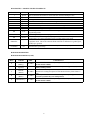
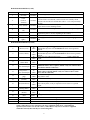
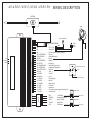
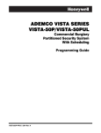
AUTOSTART
AS-4560/4563/4564/4565/4574 - SH
Manual transmission remote starter & full-featured alarm system.
INSTALLATION GUIDE
Table of Contents
What’s included……………………….……..2
Diesel Engine.…………………….……………6
Install points to remember…………………..2
Getting into Ready-Mode……………………..6
Features……………………………………….2
Staying in Ready-Mode……………………….6
Options………………………………………..2
Clutch bypass………………………………..…6
Programmable Features….…………………3
Parking Brake Wire………………………...….6
Programming transmitter.………...………..3
Programmable 5th relay………………………..7
Multi-Car Operation……………………...…3
Module Reset…………..……………….………7
Remote starter & alarm Valet Modes..…….3
Problem & Solutions…………………………..7
Transmitter function.………………..….…..4
Parking light flash diagnostics…………..…...8
Tach Adjustment……….………………..….4
Harness Description………………..….…..….8
Custom Programming Options…..….…….5
Wiring Schematic………….…..…….….……10
Tach watch Lockout………………………...5
NOTICE:
DUE TO THE POTENTIAL FOR DAMAGE TO THE VEHICLE, THE MANUFACTURER IS
NOT RESPONSIBLE FOR ANY ELECTRICAL DAMAGE TO THE VEHICLE OR TO THE
UNIT THAT HAS CAUSED VEHICLE DAMAGE DUE TO IMPROPER INSTALLATION OF
THE PRODUCT.
THIS UNIT MUST BE INSTALLED BY AN AUTHORIZED AUTOSTART TRAINED
TECHNICIAN USING ALL SAFETY DEVICES SUPPLIED.
Please review the installation guide carefully before any work begins.
WARNING
THIS UNIT IS FOR MANUAL TRANSMISSION ONLY, BEFORE INSTALLING THE UNIT
TEST THAT THE VEHICLES OEM DOOR SWITCH CONTACTS WORK WELL, AND
THAT THE PARKING BRAKE SYSTEM OPERATES PROPERLLY.
DO NOT INSTALL ON CONVERTIBLE VEHICLES UNLESS A RADAR SENSOR IS USED
TO DETECT MOTION IN THE VEHICLE.
Rev: 2.10 La – 11/30/01 Manufactured in Canada by AUTOSTART
1
WHAT’S INCLUDED
FEATURES
Please review the installation guide before
beginning the installation, particularly the
wiring diagram and the list of programming
options.
Prior to installation please be sure that all hardware
components required to install the system are in the
box.
The following is a list of components included in
the Kit:
• 1 – Control unit
• 2 – Transmitters (Depends on model)
• Plug-in shock dual zone shock sensor
• Plug-in ultra bright L.E.D
• Plug-in Valet switch
• High power 120db, 6 tone siren
• 1 - 5 Pin 14 AWG harness (Ignition harness)
• 1 - 7 Pin 18 AWG harness (Main harness)
• 1 - 11 Pin harness (Accessories)
• 1 Antenna (Link cable only with SH)
• 1 Parts Bag (hood switch, connector, wires,
warning label)
• Installation Guide
• User guide, tech bulletins.
•
•
•
•
•
•
•
•
•
•
•
•
•
•
•
•
•
•
•
•
•
•
•
•
•
•
•
•
•
•
NOTICE:
THE MANUFACTURER IS NOT
RESPONSIBLE FOR ANY RADIO OR TV
INTERFERENCE CAUSED BY
UNAUTHORIZED MODIFICATIONS TO THIS
EQUIPMENT. SUCH MODIFICATIONS
COULD VOID THE USER’S AUTHORITY TO
OPERATE THE EQUIPMENT.
INSTALLATION POINTS TO REMEMBER
•
•
•
•
•
•
•
•
•
•
•
•
When working on a vehicle always leave a
window open.
Remove courtesy light fuse if possible to
prevent battery drain.
Never Install control unit where it could
interfere with normal operation or obstruct
service technicians.
Do not disconnect the battery on vehicles
equipped with air bags and anti-theft radios.
Always use a grommet when running wires
into the engine compartment. Never run wires
through bare or sharp metal.
Always solder and tape all connections.
Never ground control unit to vehicle steering
column.
Make sure that vehicles OEM door switch
contacts and parking brake system works
properly.
Programmable high current second Ignition /
accessories / starter output
Plug in valet and L.E.D
Siren warn-away chirps
Smart-logic records last alarm state on
power up.
Programmable factory horn / siren output
5 zone protection
Smart-arm feature (system can arm virtually
any factory alarm!)
Plug-in shock sensor
Ultra bright L.E.D.
External trigger control
Pager ready
120db, small 6 tone siren
Selectable passive or active starter kill
output
Silent arm/disarm capable by remote.
Siren panic mute, without disarming.
Dedicated arm / disarm outputs
Auto zone 3 disarms with trunk release.
Electronic ultra secure Valet switch
Diagnostics via parking light
12 volt parking light output
OEM alarm control
Negative door lock outputs
Ignition controlled door locks
Anti-theft starter kill output
Anti-grind feature
Negative trunk release output
Code learning transmitter
User controlled cold weather timer
Adjustable tach search and setting
Long range receiver (up to 1500 feet range.
SH model only)
Programmable run time (4,15 or 25 minutes)
Programmable crank attempts
Programmable crank duration
LIMITED LIFE WARRANTY
OPTIONS
•
•
•
•
•
•
•
2
Remote keyless entry
Remote Trunk release
Engine kill (Starter kill)
OEM Horn control
Super-Heterodyne antenna
Multi-Car operation
Pager ready
The AS-4563/4564/4565/4574 systems feature
Multi-car operation.
This allows the owner of two Autostart systems
in two of his/her vehicles to control both systems
with one transmitter. (Both vehicles must be
equipped with an AS-4563/4564/4565/4574.
The remote transmitter of the primary vehicle
can control the starter disable system, the door
locks and the remote car starter operation of the
second vehicle. The remote transmitter of the
second vehicle can also operate the primary
vehicle
PROGRAMMABLE OPTIONS
•
•
•
•
•
•
•
•
•
Door lock pulse duration ( 1 sec, 4 sec, or two
¼ sec unlock pulses).
Programmable passive or active arming
Silent Arming/disarming chirp control
Programmable cold weather operation
Ignition controlled door locks.
Constant or pulsed Groundout when running.
Run time (4,15, or 25 minutes)
Maximum crank duration (6, 8, or 12 seconds).
Gasoline or Diesel engine operation.
REMOTE STARTER & ALARM VALET
MODES
PROGRAMMING TRANSMITTERS
To use the transmitter with your alarm/starter
system, you must first have the system learn the
transmitter's code. The system can learn a total of
4 transmitters. If more than 4 transmitters are
programmed, the oldest codes will be replaced.
(The same transmitter can be coded 4 times to lock
out all other transmitters.)
The alarm / starter unit can be placed in Remote
Starter Valet Mode to disable the capability of
starting the engine by the unit while maintaining the alarm, door locking/unlocking functions
and trunk. This is recommended if the vehicle is
to be parked in a garage or if the vehicle needs to
be serviced.
NOTE: In order to program a new transmitter
code, Alarm Valet Mode must be disabled. Also,
when programming the transmitter, make sure that
no other transmitter is in use or the alarm/starter
unit may learn it.
1. Make sure that the Alarm Valet Mode is
disabled.(LED OFF)Valet switch in the OFF
position.
2. Turn the Ignition switch to ON.
3. Open the Hood
4. Turn the Valet switch ON, OFF, ON.
5. The parking lights will come ON. You have up
to 5 seconds to press LOCK button on the
transmitter to be added to the unit, if the
operation is successful, the alarm/starter unit
will flash the parking lights 5 times quickly.
The alarm / starter unit can also be switched to
Alarm Valet Mode to stop an alarm condition or
to disable the alarm functions and the anti-theft
starter kill feature. While in the Alarm Valet
Mode, the remote starting capability, the panic
mode, door locking / unlocking functions and
trunk are still operational.
NOTE: Enabling Alarm Valet Mode is required
if you want to stop the initial alarm condition
that occurs when powering-up the system.
Using one of the next options will permit the
user to place the alarm/starter in any one of the
following combinations using the single Valet
switch:
• Normal operation
• Alarm valet mode only
• Starter valet mode only
• Alarm and starter valet modes
Note that the Alarm Valet Mode is enabled at the
end of this procedure. You should disable it to
return to normal operation. If the unit could not
read the code, repeat the operation from step 1. If
you cannot program the unit after several tries,
there may be a problem with the transmitter or
remote starter unit.
ENABLING ALARM VALET MODE
1. Make sure the Ignition key is in the OFF
position.
2. Set the Valet switch to OFF.
3. Turn Ignition ON and wait for 2 sec .
4. Set the Valet switch to ON. At this point the
LED turns and stays ON to indicate that
the Alarm Valet Mode is enabled.
5. Turn Ignition OFF and then put Valet switch
back to OFF.
MULTI CAR OPERATION (Only available on
AS-4563/ 4564 / 4565 & 4574)
*To program transmitter to second vehicle for
multi-car operation, you must press on the
transmitters TRUNK button in step 5 of
transmitter code learning.
(See above for Transmitter code learning)
3
5.
DISABLING ALARM VALET MODE
1.
2.
3.
4.
5.
Make sure the Ignition key is in the OFF
position.
Set the alarm Valet switch to ON.
Turn Ignition ON and wait for 2 sec.
Set the alarm Valet switch to OFF. At this
point the LED turns and stays OFF to
indicate that the Alarm Valet Mode is disabled.
Turn Ignition OFF and put Valet switch to
OFF.
6.
7.
8.
9.
ENABLING STARTER VALET MODE
1. Make sure you did set the alarm valet mode, as
you require.
2. Set the Valet switch ON.
*Valet switch ON = Starter will not work
With lights ON press TRUNK button of
remote transmitter at the same time.
(Parking lights will flash 1 to 7 times)
Start the vehicle using the key.
If Parking lights stays ON, then you have
selected an incorrect tach wire. (Relocate
tach wire and start from step 1) If lights go
OFF then proceed to the next step.
Allow vehicle to reach regular engine idle
speed, then press and release brakes.
(Parking lights will flash appropriate setting,
from 1 to 7 flashes)
Press TRUNK button of remote transmitter,
to save setting. (Parking lights will flash one
long flash)
NOTE: A manual adjustment should only be
done if the auto setting is not completing the
crank cycle properly in cold weather.
DISABLING STARTER VALET MODE
1. Make sure you did set the alarm valet mode, as
you require
2. Set the Valet switch OFF.
The remote starter is now in normal operation
MANUAL TACH SEARCH AND SETTING
1.
2.
TRANSMITTER FUNCTION
3.
Once programmed, the transmitter will be
operational. (Hood must be closed)
The transmitter is depended on the module type.
*The STOP Button on AS-4565 has NO function.
4.
5.
NOTE: Pressing Lock, Unlock or Start button with
the vehicle running, parking brake engaged and the
doors closed, will put the unit into Ready Mode.
6.
7.
8.
TACH ADJUSTMENTS
Autostart systems have two methods of fine-tuning
the tach signal that is generated from the vehicle,
the first method is manual tach search and setting,
and the second is automatic tach search and setting.
Either method can be used, however an automatic
search is recommended. Tach adjustment
procedures should be done every time a new
unit is installed. This is because the tach signal
from some Ignition systems can sometimes be too
high or too low, thus causing failed starts under
different temperatures.
Hold hood switch down for 4 seconds.
Release pinswitch (parking lights should
come ON)
With parking lights ON, immediately push
and release pinswitch again.
Parking lights will stay ON for 20 sec. (if
not repeat from step 1)
Press TRUNK button of remote transmitter
at the same time (Parking lights will flash 1
to 7 times)
Now you can increase or decrease the tach
setting, depending on your needs.
LOCK button will decrease the setting, and
START button will increase the setting.
After proper setting has been reached, push
TRUNK button to save setting. (Parking
lights should flash once long)
CUSTOM PROGRAMMING OPTIONS
Autostart systems are equipped with 2 custom
programming menus that allow the user to
custom fit the system according to the
installation requirements.
These options are designed to help make
interfacing with all vehicles possible.
To get into custom programming mode you
must do the following:
1. Hold pin-switch down for 4 sec.
2. Release pins-witch (parking lights will come
ON)
3. Immediately push and release
pinswitch once again. (Parking lights will stay
ON for 20 sec.)
4. Press and hold brakes, and press 1 or 2 on
remote transmitter. (LOCK for mode one,
and START for mode two) Parking lights
The procedures for tach adjustment are as
follows:
1. Hold hood switch down for 4 seconds.
2. Release pinswitch (parking lights should come
ON)
3. With parking lights ON, immediately push and
release pinswitch again.
4. Parking lights will stay ON for up to 20
seconds (if not repeat from step 1)
4
hood switch. The programming of these four
functions (and those from Mode 2) will play back
in sequence via the parking lights.
will flash once for mode 1 and twice for mode
2.
After you have entered into one of the two
programming menus you can release the brake
pedal. The unit will stay in programming mode
until the hood pinswitch is pressed or the Valet
switch has been turned OFF. (So take your time to
make the proper selection)
The menu will automatically start you at function
one, once you choose from one of the three
Options; you will automatically jump to the next
function.
To select one of the three options press the
appropriate transmitter button. (See below)
1. LOCK = Option 1
2. START = Option 2
3. TRUNK = Option 3
Once an option has been selected the parking lights
will flash 1,2 or 3 times. (Depending on option
selected)
MODE 2
This mode allows you to customize the
alarm/remote starter's control of crank cycles,
engine run time and diesel engine options.
Function 1: Engine Run Time
• Option 1
4 minutes
• Option 2* 15 minutes
• Option 3
25 minutes
Function 2: Crank Cycles
• Option 1
2 max.
• Option 2* 3 max.
• Option 3
4 max.
Function 3: Crank Time
• Option 1
6 seconds max.
• Option 2* 8 seconds max.
• Option 3
12 seconds max.
MODE 1
Function 1: Ignition Lock, Door lock/unlock
Toggled, Dual Lock Pulses
• Option 1*
Ignition Lock Enabled
• Option 2
Ignition Lock Disabled
• Option 3
Ignition Lock Disabled
& Secure Lock enabled
Note: Secure lock adds a lock pulse 4 seconds after
the module starts the engine and also 4 seconds
after it stops the engine.
Function 4: Not Used
• Option 2* Disabled
Function 5: Engine Type
• Option 1
Gasoline Engine
• Option 2* Gasoline Engine
• Option 3
Diesel Engine
* = Factory Default
Function 2: Must Select default setting.
• Option 1* Enabled
• Option 2
Enabled
TACH WATCH LOCKOUT
Function 3: Arming/disarming Chirp
• Option 1* Chirp Enabled
• Option 2
Chirp Disabled
Tach Watch lockout is a safety feature built into
the remote starter to protect the vehicle’s starter
motor. If, during remote start, the vehicle’s
engine ever cranks the entire programmed crank
time without detecting any tach pulses during the
first crank cycle, the unit will go into tach watch
lockout. The diagnostics for this is 3 quick
parking light flashes when trying to remote start
the vehicle.
If your module is in Tach Watch Lockout it is
indicating that a problem exists with the tach
signal it is receiving. Verify that the tach wire
from the remote starter is properly connected to a
good tach signal in the vehicle.
To remove the unit from Tach Watch Lockout
you must do the following:
1. Close the hood
2. Disable starter kill (if installed)
3. Start the engine using the key.
4. Let it run for at least 25 seconds, then shut it
off.
5. The module should now be out of Tach
Watch Lockout.
Function 4: Passive/Active Arming
• Option 1* Passive Arming
• Option 2
Active Arming
Function 5: Door Lock Pulse Time
• Option 1* ¾second Lock/Unlock
pulse
• Option 2
4 second Lock/Unlock pulses
• Option 3
3/4second Lock pulse,
and two 1/4second
Unlock pulses.
Function 6: Siren / OEM Horn Mode
• Option 1* SirenMode Enabled
• Option 2
SirenMode Enabled
• Option 3
OEM Horn Mode
* = Factory Default
This conclude Mode 1 programming. To get a
playback of these options, press and release the
5
NOTE: If module is still in Tach Watch Lockout
move tach wire to a better tach source and perform
an Automatic Tach Setting. Repeat steps 1 to 5.
Most manual transmission vehicles will
require the clutch to be pressed in order for
the vehicle to crank. This being true under
remote start as well, so a clutch bypass must
be performed.
A simple thing to look for when performing a
bypass, is the make of vehicle you are working on,
typically most domestic vehicles have a direct feed
wire at the clutch switch, this means that the starter
wire in the vehicle becomes continuous with
+12volts when the clutch is pressed.
While import cars typically have a relay that is
controlled with the clutch pedal. This means that
when the clutch is pressed it will send a signal to a
relay, allowing the vehicle to start.
DIESEL ENGINES
All systems are equipped with a dedicated “GLOW
PLUG” input (pin #14).
This input must be wired to the “Wait to Start”
light in the vehicle and must receive 12 volts for as
long as the light is ON. When this input is used a
protection diode must be installed on the brake
input.
Note: Diesel mode must be programmed for this to
work.
PARKING BRAKE WIRE
SETTING THE UNIT INTO READY MODE
The system has a parking brake input; this
input is used as part of the Ready Mode
sequence and must be connected. This input
is supposed to be a ground. All vehicles are
equipped with a parking brake, and all use a
negative signal.
The easiest location to find this wire is at the
parking brake housing, there will usually only be
one wire coming of the housing thus eliminating
the chance of error.
The unit does not come with channel 2 operational
from the box.
What this means is that to remote start the vehicle
you must first get the unit into Ready Mode.
To get into ready you must do the following:
1. Close all doors.
2. Make sure shifter is in neutral.
3. Start vehicle with the key.
4. Apply the Parking brake
5. Within 20sec. Push any button on transmitter
(Lights will flash 3 times quickly, and stay
ON)
6. Remove the key vehicle will stay running.
7. Exit the vehicle and close the door.
8. Press and hold any button until the vehicle
shuts down.
The vehicle will now be in ready mode, to start
press button 2 on the transmitter.
PROGRAMMABLE 5th RELAY
The 4500 series car starters are equipped with a
high current, programmable 5th relay onboard
that can be used to power a second Ignition,
accessory, or crank wire.
The programming is very simple, the unit uses a
series of 3 jumpers, each jumper represents a
function, in order to activate any one of the three
possible 2nd outputs, you must place the
jumper(supplied) on one of the three pins and
simply connect the 14awg wire to the vehicles
second ign/acc/crank wire.
REMAINING IN READY MODE
Once the vehicle is in Ready Mode you can start
and stop the vehicle at will.
However, should any of the following occur the
vehicle would come out of Ready Mode thus
eliminating the remote start option until Ready
Mode is restored.
1. Doors opened.
2. Hood opened.
3. Brakes pressed.
4. Parking brake disengaged.
5. Key turned to the ON position.
Should any of the above occur, ready mode will be
cancelled.
*NOTE: The unit will notify the user that it has
exited Ready Mode by giving three slow flashes
of the vehicles parking lights.
NOTE: ONLY ONE OF THE THREE
JUMPERS CAN BE USED AT ONE TIME.
CLUTCH BYPASSING
RESETING THE MODULE
6
The systems are equipped with a reset function that
allows the installer to erase all transmitter codes
and return all programmed options to factory
default. Make sure Alarm Valet Mode is OFF.
To reset the module:
1. Open a door.
2. Raise the Hood.
3. Turn the Ignition “ON”.
4. Press and hold brakes.
5. Turn Valet switch ON, OFF, ON, OFF, ON,
OFF, ON, OFF. (Switsh must go to ground at
least 4 times)
6. Parking lights should flash 8 times quickly.
Unit is now reset to factory defaults and all
coded transmitters are erased.
SOME COMMON QUESTIONS AND
ANSWERS
The following are some commonly asked
questions about our product, followed by
possible answers.
Q: Does the parking brake wire have to be
connected?
A: Yes the parking brake wire must absolutely be
connected.
Q: Do both door trigger wires on module have to
be connected?
A: No, only one of the 2 trigger wires must be used
or the unit will not enter ready mode.
(Refer to wire guide for proper polarity)
Q: Unit gives me one long flash when getting into
ready mode instead of three, and shuts off when
key is removed.
A: The long flash indicates that there is a problem
with the tach signal you are using. Locate another
tach wire or perform an automatic tach learn.
Q: Can the vehicle start in gear?
A: No. Because the unit must see the vehicle shut
down by remote once the user has exited the
vehicle. Knowing that the vehicle was running
when it was exited indicates that the vehicle is in
neutral.
The system then monitors the doors for entry, and
should the doors be opened the system will exit
Ready-mode.
7
DIAGNOSTICS - PARKING LIGHTS FLASH RATE
FLASHES
RATE
1
Quick
2
3
4
5
6
8
10
Quick
Quick
Quick
Quick
Quick
Quick
Quick
ON
4 sec.
ON
5 sec.
ON
20 sec.
ERRATIC
-
CONSTANT
FLASHES
Up to 60
sec.
DESCRIPTION
Alarm system armed and doors locked or end of run time or run time canceled or trunk
open or canceled cold weather or cannot start after maximum attempts of tries
Alarm disarmed and doors unlocked
Entering Cold Weather Mode or Tach watch lockout
The brake line went high and canceled cranking or run cycle
New transmitter learned
A remote start attempt was made with a tach or a vacuum signal detected
Unit Reset: Occurs when the unit is reset to factory default
The hood line went to ground during crank or run time
The hood opened and the hood switch line went to ground. This is step one of the
programming modes.
The end stage of the procedure to program transmitters.
If the hood switch is flashed (ground, open, ground), the unit went into step 1 of the
programming cycle and no transmitter activity was detected for 20 seconds.
If the unit flashes erratically (1 to 3 flashes, followed by a pause, then more flashes), it is
in playback mode. This occurs when the hood switch line is flashed twice (ground, open,
ground, open, ground).
The unit is in an alarm condition either created by an intrusion, by the panic mode or
when the unit is powered-up.
HARNESS DESCRIPTION
HARNESS DESCRIPTION (5-PIN)
PIN #
A
B
COLOR
RED
(Battery)
YELLOW
(Ignition)
SIZE
14 AWG
14 AWG
C
VIOLET
(Starter)
14 AWG
D
ORANGE
(Brake)
14 AWG
E
RED (Battery)
14 AWG
CONNECT TO
Constant + 12V source (usually the largest wire) at key switch (30 AMP inline fuse must be added).
Wire at key switch which has + 12V when key is in the Ignition (ON) and
crank (START) position.
Wire that has + 12V only when the key switch is in the crank Position.
(Attach a wire coming from pin 87A of the Starter kill relay if this feature is
used).
Wire at key switch that has + 12V when the Ignition key is in Ignition and/or
Accessories position only (not crank position).
Constant + 12V source (usually the largest wire) at key switch (30 AMP inline fuse must be added).
8
HARNESS DESCRIPTION (7-PIN)
PIN #
1
COLOR
Black
(Ground)
SIZE
18 AWG
2
Violet
(Tach or
Vacuum)
18 AWG
3
Grey (Hood)
18 AWG
4
White (Ground
out)
18 AWG
5
Orange (Brake)
18 AWG
6
Green
Yellow (Parking
lights)
18 AWG
7
18 AWG
CONNECT TO
Good solid ground, usually on the metal frame of the vehicle
Negative (-) side of coil or tach wire of electronic distributor. If the
vacuum mode is used instead, connect one side of a normally closed
vacuum switch to this wire and the other side to + 12V side protected by
the fuse.
Hood switch connector. The body of the hood switch should be grounded
to the vehicle via the mounting bracket.
Can be used for V.A.T.S., Ignition sense disable. Sends a ground signal.
Side of brake switch which has + 12V when brake pedal is pressed.
(Ignition may have to be ON, depending on the vehicle)
Data Out (Not used).
Parking lights or switch wire that has + 12V. When parking lights are
ON
HARNESS DESCRIPTION (11-PIN)
8
Brown (Lock)
18
AWG
9
Green (Unlock)
18
AWG
10
Blue (Trunk)
11
White/Yellow
(Starter Kill)
18
AWG
18
AWG
12
White/Black (-)
Door Switch Input
18
AWG
13
Orange/Black (+)
Door Switch Input
18
AWG
Yellow (Glow
plug)
White/Green
(Disarm)
18
AWG
18
AWG
Red (Siren/Horn)
18
AWG
14
15
16
Blue/Black
(Parking Brake)
White/Brown
(Rearm)
17
18
19
AUX
20
21
22
•
18
AWG
18
AWG
14
AWG
On cars with Negative Trigger door lock systems, this wire can be
attached directly to the wire that LOCKS the doors when a ground is
applied.
On cars with Negative Trigger door lock systems, this wire can be
attached directly to the wire that UNLOCKS the doors when a ground is
applied.
Pin 85 of a relay added for this feature. `````````````Sends a GROUND
signal.
Pin 85 of starter kill Relay (see diagram).
Connect to the car circuit, usually the dome light circuit, which gives a
GROUND when a door is opened. (NOTE: Only one of the two door
switch wires must be connected.)
Connect to the car circuit, usually the dome light circuit that gives +12V
when a door is opened. (NOTE: Only one of the two door switch
wires must be connected.)
Used for diesel engines. Connect to (+) when ON side of the OEM glowplug (Wait to start)
Used to disarm factory alarm.
+ 12V siren output. Connect to the positive side of the siren. **When used
with a factory horn, a relay is required to convert source to a ground
signal.
Connect to (-) OEM parking brake wire.
Used to rearm factory alarm.
(2nd Ign / ACC/ Crank) (+)
Valet
Plug in
Led
Plug in
Shock Sensor
Plug in
NOTE: Constant 12 volts wires must be connected to heaviest gauge 12 volt wires at Ignition
switch. When there are two constant 12 volt wires at Ignition switch wires A and E must be
separated (each to their own 12 volts source). When there is only one 12 volt source at Ignition
switch then and only then can they be connected together.
9
AS-4560 /4563 /4564 /4565 SH
WIRING DESCRIPTION
ANTENNA
SIREN
NON FLASHING L.E.D
Plug-In Shock Sensor
ALARM
VALET
SWITCH
(Blue)
21 - . . . . . . . . . . . . . . . . . . . . . L.E.D. / +12V.
7 - YELLOW . . . . . . . . . . . . . Parking lights (+)
6 - GREEN . . . . . . . . . . . . . . Data-out.
5 - ORANGE . . . . . . . . . . . . Brake Lights (+)
4 - WHITE . . . . . . . . . . . . . . . Ground-out.
3 - GREY . . . . . . . . . . . . . . . . Hood switch
2 - VIOLET . . . . . . . . . . . . . . Tach input (Connect to negative side of Ign coil.)
1 - BLACK . . . . . . . . . . . . . . . Chassis Ground
E
D
C
B
A
14 AWG
18 AWG
19 - . . . . . . . . . . . . . . . . . . . . . 5th Relay Output. (IGN/ACC/Crank) (+)
18 - WHITE/BROWN . . . . . . .Rearm (-)
17 - BLUE/BLACK . . . . . . . . . .Parking Brake Input (-)
16 - RED . . . . . . . . . . . . . . . . . Siren (+)
15 - WHITE/GREEN. . . . . . . .Disarm (-)
14 - YELLOW . . . . . . . . . . . . .Glow plug (+)
13 - ORANGE/BLACK . . . . . . Positive door trigger input (-)
12 - WHITE/BLACK . . . . . . . . Negative door triggerinput (-)
11 - WHITE/YELLOW . . . . . . Starter kill.
10 - BLUE . . . . . . . . . . . . . . . . Trunk (-)
9 - GREEN . . . . . . . . . . . . . . Unlock (-)
8 - BROWN . . . . . . . . . . . . . . Lock (-)
18 AWG
ACC
IGNITION
CRANK
5TH RELAY-JUMPERS
20 - . . . . . . . . . . . . . . . . . . . . . Valet / GND
RED . . . . . . . . . . . . . +12V (Battery).
ORANGE . . . . . . . . . Accessories (HEATER)
VIOLET . . . . . . . . . . Starter (CRANK)
YELLOW . . . . . . . . . Ignition (RUN)
RED . . . . . . . . . . . . . +12V (Battery).
87 no
86
87A nc
Starter wire (to solenoid)
85
Ignition
30
Starter wire (from key)
30 AMP FUSE
BATTERY (+)
30 AMP FUSE
BATTERY (+)