1
Ken-A-Vision Mfg. Co. Inc.
Glossary of Terms used in
Product
Specification Sheets
for
Cameras and Microscopes
3/7/2007
Abbe Condenser (see Condenser)
Achromat Lens (see lens)
Adapter –
See Power Supply – note all digital-only cameras (microscope or flexible-necked
camera are powered by the USB connection.
Eyepiece Adapter – For attaching Ken-A-Vision Cameras with a microscope –
accessory supplied with all KAV cameras, which allow our cameras
to be closely aligned with the eyepiece of the microscope.
Analog Output – (see also Composite Video). Analog signals are continuous electrical
signals that vary over time. Usually the variations follow that of the non-electric
(original) signal. So, for example, a telephone signal is analog, and the variations
in the wave form signal are the same as the original voice of the speaker into the
phone. Therefore, the two are analogous hence the name analog. Compare this
to a Digital output. (See Digital Output)
Anisotropic materials – (see Materials – anisotropic)
Apertures (openings in microscope Diaphragm) – (see Diaphragm)
Applied Vision ™ for Windows – (see also Software) – Ken-A-Vision’s own
software (Version 3.0 available Spring, 2007) which works seamlessly with KenA-Vision digital USB products. It allows for the capture of single images, timelapse sequences, time-lapse movies, and movies. Advanced functionalities such
as image amalgamation, measurement, and image marking are also available.
Images are exportable to Word, WordPerfect, Power Point and other equivalent
presentation programs.
AVI - Audio-Video Interleave – is the video format for Windows and the format in which
time-lapse movies or digital movies are saved when using Applied Vision ™ for
Windows.
Audio Output – Some KAV Products have built-in microphones or the ability to have
microphones plugged in using an RCA Jack. (see also Connectors)
Auto Focus- the ability of a camera to attain the correct focus on a subject, instead of
requiring the operator to adjust focus manually.
Ball and socket – attachment for head of some Ken-A-Vision cameras– literally a ball,
which rotates in a socket allows camera head to be maneuvered over a 90° range
of motion.
Binocular Head – (see Head-binocular)
2
Blooming – This is an image artifact that can affect the quality of the image
(Smear is another artifact – see below)). Blooming is an overflow of photodiode
charge into neighboring pixels. It can occur when trying to image a very bright
spot. It results in a distorted image but can be avoided by using correct lighting,
Box Dimension – Dimensions of the packaging carton in which a KAV item is shipped,
expressed in inches and centimeters (international).
Box (Boxed) Weight – Weight of item for shipment, includes both the weight of the
product and the shipping materials.
Bright/Dark Switches – On 7300 and 7600 Video Flex cameras and MVP products, a
button in the base which allows the user to brighten or darken the picture being
displayed by the camera. This adjustment is also possible using the Applied
Vision ™ for Windows software. See also Brightness.
Brightness – The quality or condition of being bright; the luminous quality of a color (as
distinct for hue) by which it is regarded as approaching the maximum luminosity
of pure white or the lack of luminosity of pure black. Brightness control, is more
properly called black level. It adds or subtracts an offset, or bias, into the red,
green, and blue signals. This control should be adjusted so that black picture
content displays as true black on your monitor. Mis-adjustment of this control is
the most common problem of poor quality picture reproduction on computer
monitors, video monitors, and television sets. The setting is somewhat dependent
upon ambient light. Brightness may be adjusted on all Ken-A-Vision products
using Applied Vision ™ for Windows. Some camera units have a button in the
base of the unit for adjustment of brightness.
Auto Brightness - is a feature of some cameras that allows them to obtain the
correct white balance, on a subject, instead of requiring the operator to
adjust white balance manually.
Brightness Compensation – same as Auto Brightness.
Manual Brightness - Ability of the user to change the brightness or darkness of a
displayed image overriding any preset (default settings).
C-Mount lens - a type of lens mount commonly found on movie cameras, television
cameras, and trinocular microscope phototubes. The C-mount lenses typically
provide a male thread which mates with a female thread on the camera. [The
thread is nominally 1 inch in diameter, with 32 threads per inch, designated as "132 UN 2A" in the ANSI B1.1 standard for unified screw threads. The register
(distance from the lens mount flange to the focal plane) is 17.526 mm (0.69
inches) for a C-mount, 12.52 mm for the otherwise identical CS-mount]. The
letter "C" is said to stand for "cine", the original application being movie camera
lenses.
3
Cable – KAV supplies various cables with its products. These include USB cables
(usually 5 ft. - 1.5 m.), Composite (12 ft.- 3.6 m.), S-video (12 ft-3.6 m).
Cable length – (see Cable)
Cat. 5 Cable – (see connectors)
CCD Camera - a Charge-Coupled Device. The specific technical detail is that in a CCD
sensor, every pixel's charge is transferred through a very limited number (often
one) of output nodes to be converted to voltage, buffered, and sent off-chip as an
analog (video) signal. All of the pixel can be devoted to light capture, and the
uniformity of the output (a key factor in image quality) is high. KAV Video
(analog) cameras and also cameras capable of outputting both Analog and Digital
signals simultaneously, will use a CCD camera.
Ceiling mount – (Tile Support Rail) - Provided with the Ceiling DocCam II to allow
installation of this camera between the tiles in a standard drop (suspended) ceiling
[2’ x 2’ (0.6m x 0.6m) tiles or 2’ x 4’ (0.6m x 1.2m) tiles]. It is designed to be
installed at heights between 8’ and 12’ (2.44 m to 3.66m). The main support is a
metal plate [8.5" x 24" (21.59 x 60.96 cm)] which distributes the weight of the
camera on the support rail grid, preventing tile warping. A Plenum-rated
enclosure for the camera attaches to this metal plate, and allows the camera to
hang between two ceiling support rails.
Charger - (microscopes and cameras) – (see power supply)
Chrominance - Portion of video signal that carries hue and saturation color information.
(see also luminance).
Coarse/Fine Adjust – On microscopes Coarse and Fine Adjustment knob(s) are located
on the side of the microscope frame, usually below the stage, which allow the
observer to adjust the focus of the microscope. There are various kinds of coarse
and fine adjust mechanisms.
Coaxial Controls – Consists of two knobs where one smaller knob (fine adjust)
is centered on top of another, larger knob (coarse adjust), both on the same
axle.
Singlet Control – one knob does both coarse and fine adjustment. Excellent for
novice and young microscope users. Only the 1100, 1180, 1200, 1201,
and 1252 have a single knob, which operates a rack and pinion gear set.
Rack and Pinion – refers to the interlocking of a series of gears and cams that
allows the coarse and fine adjustment knobs to interact. Most Ken-AVision microscopes have a rack and pinion system except the ESH 200,
4
Planetary - Coaxial coarse and fine focusing, with planetary reduction gear
system, is a more advanced version of the basic rack and pinion system.
This is found on the 1900, 2700, 2800 and 3300 series compound
microscopes.
Coaxial Controls – (see coarse/fine adjust)
Composite Video - composite Video signal combines luminance and chrominance in
a single signal. Differentiated from S-Video, where the two signals (brightness
and color) are carried separately.
Compression - The digital representation of media in an efficient storage format. For
video, motion-JPEG is often used. Compression may produce a poor quality
image, in that the original picture cannot be reconstructed exactly.
Condenser (Microscopes) - a lens or lens system located either within or below the stage,
which helps to focus the light coming into the specimen from the microscope’s
light source. All Ken-A-Vision compound microscopes ( have at least a single
lens located within the opening of the stage.
Standard – glass lens focusing light from illuminator in base of microscope.
Abbe - a moveable lens system under the stage (sub-stage) that can be moved up
and down vertically, regulating the amount of light from the illuminator
(light source). It contains an adjustable iris to control the beam diameter
of the light. An experienced microscopist can have excellent control over
the amount of light illuminating the slide by manipulating the iris, or
moving the Abbe condenser up or down. It is very useful at higher
magnifications, and for sophisticated microscope use.
Connectors – refers to the types of connectors made between a KAV camera and a
computer, TV monitor, VCR, DVR, Audio-Visual Projector, or other display
device.
Audio – Usually also an RCA jack and composite cable. Usually the plug and
jack are colored white.
Cat. 5 cable – Fifty foot (50’ or 15.2m) cable provided with the Ceiling DocCam
II, which has RU-45 Jacks at each end, connecting the Ceiling DocCam II,
with the RJ-45 plug on the wall plate provided with the Ceiling DocCam
II. Function of cable is to carry the video (analog) signal to the wall plate
for further distribution of the signal to in room devices such as TV,
projectors and the like. The cable also carries power to the camera.
RCA – Is generally accepted as the name of the (usually) color-coded jack used to
carry a composite signal. KAV uses an RCA as the composite output,
{though in some models an S-Video jack is also available).
5
RJ-45 – Plug and connector. Used by Ken-A-Vision only on the Ceiling DocCam
II, it is the connectors on either end of the Cat. 5 cable provided
with this camera, and provides S-video, composite video, power
and RS-232 control, between the camera and the wall plate.
RS-232 – (DE-9 connector for as RS-232 interface) Found on the wall plate of the
Ceiling DocCam II and is used to connect the camera to control systems
for monitoring such as Crestron or AMX.
S-Video – Separate video, also known as Y/C (or erroneously, S-VHS and
"super video") is an analog video signal that carries the video data as two
separate signals (brightness and color), unlike composite video which
carries the entire set of signals in one signal line. [S-Video, as most
commonly implemented, carries high-bandwidth 480i or 576i resolution
video, i.e. standard definition video. It does not carry audio on the same
cable. It is a four (4) pin connector, with each signal pin paired with its
own ground pin]. Ken-A-Vision supplies two lengths of S-video cables:
12’ (3.66m) – shipped standard with Video Flex 7300, and 7600,
Flex Cam iCam Digital (910-171-102), FlexCam (910-171110), StudentCam (910-171-120), IDCam (910-171-125),
TeachCam (910-171-150) and MVP Products.
25’ (7.6m) – shipped standard with the Ceiling DocCam II (910171-066).
USB - Universal Serial Buss a serial bus (connection) standard to interface
devices. USB can connect peripherals such as mouse devices, keyboards,
gamepads and joysticks, scanners, digital cameras, printers, external
storage, etc. For many devices such as scanners and digital cameras, USB
has become the standard connection method. [USB also replaced parallel
ports which formerly were common on computers].
USB 0.9, 1.0, 1.1 previously common specifications. KAV devices are
1.1 unless designated USB 2.0.
USB 2.0 - as of 2006 the USB specification is at version 2.0 (with
revisions). This is a higher data transfer rate than the 1.1 specification. The
USB 2.0 specification was released in April 2000 and was standardized by
the USB-IF at the end of 2001. Equipment conforming with any version
of the standard will also work with devices designed to any previous
specification (known as backward compatibility). All KAV USB 2.0
cameras are backward compatible, however there will be a diminution of
resolution and pixelization will be more noticeable.
Video - (usually a composite [RCA] connector) - Composite video is the format
of an analog television (picture only) signal before it is combined with a
sound signal. It is usually in a standard format such as NTSC, PAL, or
SECAM. [It is a composite of three source signals called Y, U and V
(together referred to as YUV) with sync pulses. Y represents the
6
brightness or luminance of the picture. U and V between them carry the
color information]. Usually the plug and jack are colored coded yellow.
CMOS Camera – Complementary Metal Oxide Semiconductor - In a CMOS sensor, each
pixel has its own charge-to-voltage conversion, and the sensor often also includes
digitization circuits, so that the chip outputs digital bits which may reduce the area
available for light capture. The capture chip requires less off-chip circuitry for
basic operation. All purely Digital KAV cameras are CMOS cameras.
Contrast Control button – Contrast Control might be better called Picture. It applies
a (gain) to the red, green, and blue signals. It affects the luminance (proportional
to intensity) that is reproduced for a full white input signal. Once BRIGHTNESS
is set correctly, CONTRAST should be set for comfortable viewing brightness.
Clips – (see Stage Clips)
Composite Output – Composite video is the format of an analog television (picture only)
signal before it is combined with a sound signal. It is usually in a standard format
such as NTSC, PAL, or SECAM. [It is a composite of three source signals called
Y, U and V (together referred to as YUV) with sync pulses. Y represents the
brightness or luminance of the picture. U and V between them carry the color
information]. Usually the plug and jack are colored coded yellow.
Compound microscope - In the original ‘simple’ microscopes, a single light path went
through the object viewed and one (1) lens, increasing the visibility of the object
by some amount (magnification). (one light path, one lens = simple microscope)
Compound refers to the fact that in order to enlarge an image, a single light path
passes through a series of lens in a line. Each lens magnifies the image over the
previous one. (One light path, multiple lenses = compound microscope) Usually,
a modern compound microscope has multiple lenses (objective lens) within a
single eye tube, and a series of three or four objective lenses on the ‘head’ which
can be rotated into place. The image produced is a two dimensional (2-D) image.
Comprehensive Scope – Specific name given to the T-1900 series of Ken-A-Vision
Compound microscopes.
Cordless (microscope) – Ken-A-Vision cordless microscopes utilize a patented, Nickel
Metal Hydride (NiMH) battery system, allowing the microscopes to be operated
for approximately 40 hours between charges. Every microscope is shipped with
its own charging unit, or the microscopes may be charged using our patented
Cordless Microscope Multi-Charger (SCGN06), which will charge 8 microscopes
simultaneously. All cordless microscopes should be charged immediately upon
reception by user, and should always be charged prior to any storage of more than
2 weeks duration.
7
CoreScope – The proper name of our T-1200 series of microscopes both non-digital and
digital. These microscopes are designed primarily for use in Elementary and
Middle School, and have a Singlet (see Coarse/Fine Adjust) knob for focus
adjustment.
Dark/Bright switch – (see bright/dark switch)
Depth of field – With video cameras, the depth of field is the area between the nearest
object that is in focus and the furthest object in focus
Diaphragm (Microscopes) - the diaphragm of a microscope regulates the intensity of
light entering through the slide and into the objective lens. Ken-A-Vision
microscopes come with two types of diaphragms.
Disc – Consists of a series (6 or 8) of openings (apertures) of increasing
diameter, located just below the stage.
Iris - A variable, shutter type adjustment which can be set anywhere
from full closed to fully open, allowing a very precise adjustment
to the amount of light entering into the objective lens.
Field – AN iris type light control, located between the light source and the
sub-stage condenser, allowing even greater control of light.
Digital Output – Digital signals are non-continuous, they change in individual steps. They
consist of pulses or digits with discrete levels or values. The value of each pulse is
constant, but there is an abrupt change from one digit to the next. Digital signals
have two amplitude levels called nodes, the values of which are specified as one
of two possibilities such as 1 or 0, high or low, true or false and so on. The signal
emitted by a Ken-A-Vision camera, on a USB cable connected to a computer is a
digital output or signal. (see also Analog output)
Digitize - term used to describe the conversion of an analog video or audio signal into a
digital signal that can be used by a computer.
Dimension(s) (or size) – Refers to the actual physical dimensions of a Ken-A-Vision
product, usually given as length times width times height. For example, a T-1954
microscope is 8.5" x 5" x 14.5" (21.6cm x 12.7cm x 36.8cm)
DIN – (Deutsche Industrie Normen) represents an international standard for microscope
objectives. This standard specifies the exact threading and focal length, and
insures compatibility with lenses from any microscope manufacturer in the world.
Diopter - The purpose of a Diopter is to allow for a difference in eyesight acuity
between two ‘different eyes’. It is present on one eye-tube of all Dual-headed
(see Head) Ken-A-Vision microscopes, one eyepiece of a Ken-A-Vision binocular
microscope (see Head) or on all Ken-A-Vision digital microscopes. The purpose
of a Diopter is to allow compensation of the differences in eyesight between two
users (Dual-headed microscopes), between the two eyes of a single user
(Binocular microscopes) or between the camera and the view seen in the eyepiece
8
(Digital microscopes) by the user because the camera is at a different focal length
then is the camera position.
Discovery Scope Kit – An accessory for Video Flex and MVP cameras which allows for
hands-free observation of specimens by placing the specimen right in front of the
camera lens at a short distance to allow magnification to occur. The kit consists
of a clamp for attachment to the flexible neck of the camera, a telescoping tube, a
set of alligator clips to hold a specimen like a coin, stamp or bug; a bag holder
into which specimen’s may be placed such as pond water, or moving organisms;
two resealable and reusable bags; and 2 waterproof plastic boxes for holding
specimens.
Dissecting Microscope (see Vision Scope)
Dual Opposing Head – (see Head – Opposing)
DVR – Digital Video Recorder (DVR) (or personal video recorder (PVR)) is a device
that records video without videotape to a hard-drive -based digital storage
medium. The term includes stand-alone set-top boxes and software for personal
computers which enables video capture and playback to and from disk. These are
replacing VCRs as a preferred way of recording images.
Exposure (see also Contrast) – is the amount of illumination reaching the imaging chip of
a camera – it is regulated by an internal iris in most Ken-A-Vision cameras or
may be adjusted by using Applied Vision ™ for Windows software.
Eyepiece (microscopes)
Widefield - an eyepiece with an acromatic doublet lens which allows the observer
to viewing through the whole lens diameter rather than being limited to
viewing only in the center of the field. The enlarged opening allows a
large non-distorted viewing of the microscope field, making it easier,
particularly for novice observers to use the microscope, because the
position of the eye does not have to be ‘perfect’. Ken-A-Vision
microscopes come standard with 10X, widefield eyepieces
Pointer – inside the eyepiece of Ken-A-Vision microscopes is a fine hair ‘pointer’
which goes about half way across the visual field. The purpose of the
pointer is so that a user might place a specific part of the field at the end of
the pointer, allowing them to them share it with another user. E.g. a
teacher might put a cellular structure at the end of the pointer so that they
are sure the student is looking at the correct object.
Field Diaphragm (see Diaphragm)
9
Flexible
Flexible Neck (KAV) – includes the Video Flex, Vision Viewer and MVP lines of
Ken-A-Vision cameras.
Flexible Neck (by KAV) – includes the flexible necked cameras now
manufactured and sold by Ken-A-Vision, that were formerly made and
sold by ClearOne (Video Labs) – (acquired by Ken-A-Vision in 2006).
Flip – is a property of some Ken-A-Vision camera drivers, not of Applied Vision ™ for
Windows Software. In those cameras that have the Flip functionality, once
Applied Vision ™ for Windows is open, click on the Video Tools (Hammer,
Pliers and Screwdriver), to open the Video box. Within the Video box click on
the camera (left side of box). Depending upon the camera driver that has been
activated, a series of tabs will open. Select the tab Video Image, and within this
box there will be either the choices Flip and Mirror, OR Vertical Flip and
Horizontal Flip. Using either of these paired commands will, convert the image
from one document orientation to the opposite document image.
Mirror – Will shift the image to the mirror image of the original.
Flip – Will turn the image 180° from the original image.
Flip Horizontal – will turn the image 180° from the original image.
Flip Vertical –Behaves like Mirror, will shift the image to the mirror image of the
original.
Flip Horizontal – (see Flip)
Flip Vertical – (see Flip)
Floating Stage – A microscope stage which may be moved in multiple directions with the
microscope slide clipped on its surface. It replaces the need for a mechanical
stage on some microscopes.
360° – Found on the T-1700 series of microscopes, allows movement of the stage
in a 360° range.
x/y – Found on the T-1941 Dual Purpose microscope, allows movement of the
stage along the X and Y axes, but not Z, so therefore not 360°.
Fluorescent Control Switch – Found on 7300 and 7600 Video Flex and MVP cameras.
There is also a fluorescent control found in the Applied Vision ™ for Windows
software. Both will reduce the flicker caused by the ballast some older
fluorescent lights in a room, and improves some dim light problems.
10
Fluorescent (light source for microscopes) – Source illuminator on some models of
microscopes. At Ken-A-Vision fluorescence illumination is now optional on a
limited number of microscopes. Primary benefit of a fluorescent light source is
that the amount of heat generated by the illuminator is severely reduced from a
traditional incandescent or tungsten filament light.
Fluorescence microscope – Ken-A-Vision does not currently carry any of these
specialized microscopes necessary for detecting organelles that have been marked
with fluorescent dyes for rapid location and identification.
Focus
Auto – see Auto Focus
Coarse/Fine Adjust – see Coarse/Fine Adjust
Manual – see Manual Focus and Quick Focus
Quick Focus – see Quick Focus
Focusing types (on microscopes)
Coaxial Controls – Consists of two knobs where one smaller, knob (fine
adjust) is centered on top of another, larger knob (coarse adjust).
This is a feature of all Ken-A-Vision compound microscopes
except the 1200 series for elementary students.
Singlet Control – one knob does both coarse and fine adjustment.
Excellent for novice and young microscope users.
Rack and Pinion – refers to the interlocking of a series of gears and cams
that allows the coarse and fine adjustment knobs to interact. All Ken-AVision microscopes have a rack and pinion system except the ESH 200.
Focal (focus) distance –
Microscope, focal distance is the space between the end of an objective (lens) and
the surface of the specimen or slide. As magnification increases, focal
distance decreases.
Camera – focal distance is the space between the lens of the camera, and the
surface of the object being converted into an image. With Ken-A-Vision
cameras, as the focal distance decreases, the magnification increases.
Frame - One complete still image of video media. Video media is made up of a series of
frames. Each video frame has two interlaced fields.
Frame rate – (Image rate) - number of times per second the image is refreshed per
second. NTSC has a general frame rate of approximately 30 frames per second
(fps) (actual 29.97). PAL has a frame rate of 25 fps). (See also Video Standards –
NTSC and PAL below)
Freeze – Button found on MVP products and the T-1955 (Network Memory Scope)
which will cause the image to be fixed (not live) until button activated again.
11
Halogen light (see Light sources)
Hanover Bars – (see Video Standards-PAL)
Head (Cameras)
Ball and socket - literally a ball, which rotates in a socket allows camera head to
be maneuvered over a 90° range of motion. Found in all Video Flex and
Vision Viewer Cameras except the 2100 (Explorer), 5500 (ClipCam),
7811 (BookCam), 7821 (ShopCam), 7870 (PhysicsCam), and 910-171066 (Ceiling DocCam II). With the exception of the DocCamPro™ AV
(910-171-010) none of the FlexCams by Ken-A-Vision are ball and
socket.
90° Fixed – Camera head is fixed to the end of the flexible neck. All the
exceptions listed above under Ball and Socket, including the FlexCams by
Ken-A-Vision (except the Ceiling DocCam II) are 90° Fixed head
cameras.
Head (Microscopes)
Monocular - single eye tube, set at 45o to the head for viewing by
one observer at a time.
Dual Opposing) Head - Two eyepieces, each of which are at 45o to the
head of the microscope, and set at 180 o from each other. This allows two
observers to use the microscope simultaneously, for example a teacher and
the student.
Binocular – Two eyepieces, usually on a slide mechanism. The interpupillary
distance is adjusted side-to-side, by sliding the eyepieces towards and
away from each other.
Seidentopf binocular – Two eyepieces, with the head designed so that by
increasing or decreasing the distance between the two eyepieces
(interpupillary distance) is done by twisting the eyepieces in an
up and down arc motion similar to most binoculars.
Triocular - This microscope has a binocular head for viewing and an additional
eyepiece for a camera mount. Ken-A-Vision trinocular heads have an
80:20 split feature so that when a slide adjustment feature is in position
one, 80% of the light comes to the camera and 20% comes to the binocular
head, allowing a view of what the camera will see. In the opposite
position the slide allows 100% of the light to get to the binocular
eyepieces.
12
Tucked Reverse – In a compound microscope, the objectives are placed such that
they are positioned back towards the arm of the microscope allowing for
ease of inserting or removing slides from the stage.
Vertical binocular – Only the Ken-A-Vision T-2400 has this feature. The
binocular lens are placed vertically, directly above the objective lenses.
45° Angle - All Ken-A-Vision microscopes are position with a 45° angled head,
allowing for an ergomatically comfortable position for the average
microscope user.
360 ° Rotation – By loosening a knurled set screw, most Ken-A-Vision
microscopes allow for the head to be rotated 360° on the microscope
stand, so that the eyepiece can be viewed from any side without moving
the whole microscope.
Image Rate – (see Frame Rate, and Video Standards)
Image Resolution - A measurement of the quality of a video image based on the number
of pixels that make up the image.
Incident Light (see Light Sources)
Iris (Camera) – As a general principle, the iris of a camera adjusts the brightness of the
image. On CCD cameras, there is a physical iris whose opening is adjusted by
electrical impulse. The iris of a camera changes the incident light striking the
video chip. On CMOS cameras, white balance is adjusted by driver properties,
changing the brightness of the image. (see also White Balance)
Iris diaphragm (microscopes) – a device consisting of thin, overlapping metal plates that
can be adjusted to form an aperture of varying diameter regulating the amount of
light entering the microscope. In Ken-A-Vision microscopes it is included as a
part of a sub-stage Abbe condenser apparatus. (see also Condenser-Abbe)
JPEG - Joint Photographic Experts Group. An international standard for still picture
data compression. In Applied Vision ™ for Windows, this is the default storage
mode for single images.
Ken-A-Vision Capture for Macintosh – (also see software) – A viewing and capture
application for Macintosh OS 10 and above. It is provided with all cameras
which are supported on OS 10. User is then able to utilize all Macintosh image
software available to them on their Macintosh computer.
Ken-A-Vision Cool Lighting (see light sources)
13
Kensington (lock and slot) - A Kensington Security Slot (also called a K-Slot or
Kensington lock) is a small hole found in the base of Ken-A-Vision cameras. It is
used for attaching a lock, in particular those from Kensington Technology Group.
The locks are generally secured in place with a key or some mechanical pin
device and attached with a strong metal cable to some permanent object, such as a
heavy table or other similar equipment. Provides limited security.
Kohler Illumination (microscopes)– Kohler illumination is a technique that provides
optimum resolution and contrast in a light microscope by aligning and focusing
the illumination and critical setting the apertures of the microscope to best match
the objective lens Numerical Aperture. (see any good book on microscopy) – (see
also Numerical Aperture)
Laser alignment (tool, guide. or feature) – found on the Ceiling DocCam II (910-171066) camera. When laser is activated it ensures proper document orientation by
indicating where a document should be placed for best viewing on the table below
the camera. Laser displays for five seconds when the camera is first powered on.
Lens(es)
Achromat - A combination of lenses made of different glass, used to produce
images free of chromatic aberrations.
f-stop (e.g. f1.4-f2.8) - the f-number (sometimes called focal ratio, f-ratio, or
relative aperture of an optical system expresses the diameter of the
entrance pupil in terms of the effective focal length of the lens. It is the
quantitative measure of lens speed.
8 mm – Standard lens on all Video Flex cameras and all FlexCams by Ken-AVision. Refers to the physical diameter of the original lens. Field of view
is slightly smaller then the field of view of a 6 mm.
6 mm - Standard lens of all Vision Viewer cameras. The field of view of a 6 mm
lens is slightly larger than that of an 8 mm lens.
C-Mount – see C-mount lens
Objective lens - (see Compound lens)
Light sources
Ken-A-Vision Cool Light - becoming standard on all ESH, T-1100, T-1200,
T-1700, T-1900 Ken-A-Vision microscopes. It consists of a variable
(depending upon model) number of specialized LED lights. Importance is
that the light source does not generate significant heat, damaging living
specimens.
14
Halogen – Incandescent bulb in which the filament is tungsten, but the gas filling
the glass envelope is halogen (iodine or bromine generally). The presence
of the halogen increases the length of the bulb’s life. Halogen lamps tend
to be run at higher temperatures which allows higher luminous efficacy,
apparent brightness, and whiter color temperature (see Color
Temperature). Microscopes with halogen lamps, give more intense, white
light, but also emit considerable heat which can quickly kill living
specimens.
Transmitted (light) – In microscopes, transmitted light refers emitted from the
illuminator (light source) and passes through the slide or specimen to the
objective lens.
Incident (light) – refers to any light that falls on the specimen or slide on the
microscope. In Dissecting (Stereo microscopes or Ken-A-Vision
VisionScopes) the incident light is provided by a top of supra-stage light
source, which illuminates the top surface of the specimen or slide. The
light is generally not transmitted through the specimen or slide.
Tungsten - In most standard incandescent lights, the filament that is activated and
glows to emit light is made from Tungsten. Characteristic of Tungsten
lamps is that they give intense, white light, but also emit considerable heat
which can quickly kill living specimens.
Light Rheostat – a device which allows for adjustment of light intensity on a microscope,
similar to a room dimmer switch. Actual effect is produced by placing a variable
resistor in the circuit causing the current applied to the light to vary.
Light Sensitivity – In Ken-A-Vision cameras, refers to the amount of incident light
needed to activate the camera chip. The smaller the number the less light needed
to produce an image on the camera.
Luminance - Black and white portion of a video signal representing picture contrast and
brightness.
Macro – A combining form which meaning long (in extent, or duration) large, enlarged,
or elongated. It is the opposite of –micro.
Magnification - is to make something larger in size then it really is by use of lenses. In
microscopes, this is usually indicated by the abbreviation “X”. So a 10X eyepiece
will magnify the image on a slide by 10 times. To determine total magnification
of a specimen by a microscope, simply multiple the eyepiece magnification times
the objective magnification. (for example –if the eyepiece is 10X and the
objective is 10X then the total magnification would be 100X ). As magnification
increases, generally more light is needed to maintain the same level of resolution
(defined below)
15
Manual Focus – any operation where the user or operator must change the focal length by
adjusting the coarse/fine adjust of a microscope, or rotate the focusing ring of a
camera.
Materials – What a thing is or made of.
Isotropic – having physical properties, as conductivity, elasticity or light
transmittance that is the same in all directions.
Anisotropic – NOT having physical properties, as conductivity, elasticity or light
transmittance that is the same in all directions.
Opaque – a material which will not allow light to pass through.
Mechanical Stage (Stage Manipulator) – a specialized kind of mechanism, into which a
slide may be insrted, and then the slide moved around with great precision, and in
very small increments. Most mechanical stages have both an ‘X’ and a ‘Y’
Vernier, allowing exact marking of location of an object on a microscopic slide.
Megapixel - A pixel (short for picture element, using the common abbreviation "pix" for
"picture") is a single point in a graphic image. Each such information element is
not really a dot, nor a square, but an abstract sample. The intensity of each pixel is
variable; in color systems, each pixel has typically three or four dimensions of
variability such as red, green, and blue, or cyan, magenta, yellow and black. A
Megapixel is 1 million pixels, and is a term used not only for the number of pixels
in an image, but also to express the number of sensor elements of digital cameras
or the number of display elements of digital displays. For example, a camera with
an array of 2048×1536 sensor elements is commonly said to have "3.1
megapixels" (2048 × 1536 = 3,145,728).
Micro – a combining form meaning little, small or minute. It is the opposite of –macro.
Mirror – (see Flip)
Monocular head (see Head-monocular)
Mirror – (see Flip – Mirror)
Multi-Charger – An eight station unit for charging Ken-A-Vision Cordless Microscopes
which contains a microprocessor for each charging station controlling the charge
to each unit receiving. The microprocessor prevents overcharging and is energy
efficient. It charges the NiMH (Nickel Metal Hydride) batteries found within
Ken-A-Vision Cordless Microscopes within eight hours. Great for charging your
microscope while they are being stored. Individual LED indicators indicate when
microscope is charging and when it is fully charged. Each charging station has a
6 foot cord for connecting to the microscope.
16
NiMH Batteries (Nickel Metal Hydride) - Ken-A-Vision batteries for cordless
microscopes are specially made batteries of the NiMH type. Technically A nickel
metal hydride battery, abbreviated NiMH, is similar to a nickel-cadmium
(NiCd) battery but has a hydrogen-absorbing alloy for the anode instead of
cadmium. Like in NiCd batteries, nickel is the cathode. A NiMH battery can
have two to three times the capacity of an equivalent size NiCd.
Nickel Metal Hydride Batteries (see NiMH)
Non-cordless (microscope) (wired) – Ken-A-Vision microscopes are all shipped with a
removable power cord (or charger/adapter), Exceptions include the T-2400, T-2700, and
T-3300 series of microscopes, which have a permanently mounted power cord.
NTSC – (see Video Standards)
Numerical Aperture - the numerical aperture (NA) of an optical system is a
dimensionless number that characterizes the range of angles over which the
system can accept or emit light. [In microscopy, the numerical aperture of an
objective lens is defines as NA = Π sine Θ, where Π is the index of refraction of
the medium in which the lens is working (1.0 for air, 1.33 for pure water, and up
to 1.56 for oils), and θ is the half-angle of the maximum cone of light that can
enter or exit the lens.] In microscopy, NA is important because it indicates the
resolving power of a lens. The size of the finest detail that can be resolved is
proportional to λ/NA, where λ is the wavelength of the light. A lens with a larger
numerical aperture will be able to visualize finer details than a lens with a smaller
numerical aperture. Lenses with larger numerical apertures also collect more light
and will generally provide a brighter image.
Objective Lens(es) – Objective lenses are designed to maximize the ultimate resolution of
the microscope. Three criteria are balanced in the design of a high resolution
objective. These include consideration of the wavelengths of light emitted by the
light source used on the microscope, the refractive index of the space between the
front of the objective lens and the specimen (focal distance) and the angular
opening (aperture) of the light cone captured by the objective.
Ocular (see eyepiece)
Opaque materials (see materials)
Output – Electronic
Analog – see Video output
Audio – see Audio output
Digital – see Digital output
Network – see Network output
RJ-45 – see Network output
S-Video – See S-video output
Video – see Video output
15 pin D Sub – see Video output
17
Output – Video Resolutions Expressed in Pixels
VGA - 640 X 480
SVGA - 800 X 600
XGA - 1024 X 768
SXGA+ - 1400 X 1050; 1280 X 960 also in some sources
UXGA - 1600 X 1200
QXGA - 2048 X 1536
QSXGA+ - 2800 X 2100
QUXGA - 3200 X 2400
PAL – see Video Standards
Pixel - A single picture element. The smallest element in a graphic image. Pixels are
combined with other pixels to make up a graphic image. Picture quality increases
as the number of pixels increase in a measured area of an image.
Planetary – (see Coarse/Fine Adjust)
Pointer (see eyepiece pointer)
Positive/Negative Switch – Reverses the image of the camera, from the positive colored
image, to its video negative image.
Power Adapter – (charger) - Ken-A-Vision cordless instruments, and some cameras are
supplied with an removable power cord, which may be either used as a standard
wall plug in source of power for the instrument, or as a charger of batteries in
cordless units. The exact one provided is dependent upon the specifications of the
purchaser, or in lieu of that the specifications of the country of use.
Power Supply – Country specific eight foot UL approved wire with the correct male plug
for country of use, or as requested by the purchaser.
PrepScope – The name given to the T-1200 series of Ken-A-Vision microscopes. They
have 4X, 10X, AND 40X objectives and a single large coaxial coarse/fine adjust
knob for use by Elementary and Middle School children.
Quick Focus™ – Trade marked feature of the Video Flex line of Ken-A-Vision cameras.
Within a 90° turn of the knurled knob on the face of the camera, the user can
focus from extreme close up (less than 1 inch from front of camera) to infinity.
Rack and Pinion – (see Focusing Types)
RCA connector – (see connectors)
18
Resolution (See Appendix A for more exhaustive detail on video resolution)
Image Resolution - A measurement of the quality of a video image based on the
number of pixels that make up the image.
Microscope - is the ability to tell two points apart as separate points. If
the resolving power of your lens is 2um that means two points that are
2um apart can be seen as separate points. If they are closer together
then that, they will blend together into one point.
Video - While all (NTSC) TV sets and program material (broadcasts, tapes, disks,
etc.) use the same 525 scan lines, the advertised resolution (240, 425, 500,
etc.) refers to the horizontal resolution which is the number of side by side
dots that can be reproduced within any one line.
The number of scan lines is the limit for vertical resolution, the number of
dots in a column that can be reproduced. It is pretty much the same for all
decent NTSC TV sets of moderate or large size. (See also Appendix A)
(For definitions of various advertised resolutions – XGA etc. see Output –
Video Resolutions Expressed in Pixels)
Rheostat – (see Light Rheostat)
RJ-45 connector – (see connector – RJ 45)
RS-232 connector – (see connector – RS-232)
Seidentopf Binocular head – (see Head-Seidentopf)
Singlet Control - see coarse/fine adjust
Size - (see Dimension)
Smear – This is an image artifact that can affect the quality of the image
(Blooming is another artifact – see above). Smear is defined as light leakage into
the transfer part of the CCD camera chip, causing unwanted vertical lines in the
image. It results in a distorted image but can be avoided by using correct lighting,
Software
Applied Vision ™ for Windows - Ken-A-Vision’s own software (Version 3.0
available Spring, 2007) which works seamlessly with Ken-A-Vision digital USB
products. It allows for the capture of single images, time-lapse sequences, timelapse movies, and movies. Advanced functionalities such as image
amalgamation, measurement, and image marking are also available. Images are
exportable to Word, WordPerfect, Power Point and other equivalent presentation
programs.
Ken-A-Vision Capture for Macintosh – Ken-A-Vision Capture is a Mac OS X
application allowing users to capture images, record movies, and display
full-screen video from supported Ken-A-Vision cameras.
19
Stage Clips – Ken-A-Vision patented spring loaded clips provided as standard on all
Ken-A-Vision microscopes. (Except ESH models)
Stage Manipulator (See Mechanical Stage)
Standards – see Video Standards
S-Video (output) – (see also connectors) - Separate video, also known as Y/C (or
erroneously, S-VHS and "super video") is an analog video signal that carries the
video data as two separate signals (brightness and color), unlike composite video
which carries the entire set of signals in one signal line. [S-Video, as most
commonly implemented, carries high-bandwidth 480i or 576i resolution video,
i.e. standard definition video. It does not carry audio on the same cable. It is a
four (4) pin connector, with each signal pin paired with its own ground pin].
Stereo Microscope (see Vision Scope)
Transmitted Light (see Light Sources – transmitted light)
Triocular (see Head – Trinocular)
Tucked Reverse (see Head – Tucked Reverse)
Tungsten light or lamp (see light Sources)
USB – Universal Serial Bus Controller – see Connections
USB Adapter – An accessory allowing the conversion of an analog signal to a digital
signal. Currently Ken-A-Vision sells two such units USBAD2 (which comes with
Applied Vision ™ for Windows and Ken-A-Vision Capture for Macintosh) and/or 910171-318, which has video pass-through capability.
VCR – Video Cassette Recorder – Records image captured on camera (or from an analog
source such as a TV, and places the signal usually on VHS or similar tape.
Venetian Effect - Venetian Blind Wipe - A transition that produces the effect of having
an outgoing clip displayed in strips over the incoming clip. The strips open, like a
Venetian blind, to reveal the incoming clip.
Vertical Binocular (see Heads)
Video Output
Composite – see Composite Output, also Connectors Composite
S-Video – see S-Video, also Connectors S-Video
20
Video Standards NTSC - is the analog television system in use in Canada, Japan, South
Korea, the Philippines, the United States and a few other countries in the
Americas. It is named for the National Television System(s) Committee,
the U.S. standardization body that adopted it. In 1941 the committee
settled on a 525-line transmission standard, with a frame rate of 30 frames
per second, with an aspect ratio of 4:3, which is still basically the United
States Standard to this day. The NTSC format is used with the M format
which consists of 29.97 interlaced frames of video per second. Each frame
consists of 484 lines out of a total of 525 (the rest are used for sync,
vertical retrace, and other data such as captioning). The NTSC refresh
frequency was originally exactly 60 Hz in the black and white system,
chosen because it matched the nominal 60 Hz frequency of alternating
current power used in the United States
PAL – short for phase-alternating line, phase alternation by line or phase
alternation line, is a color encoding system used in large parts of the
world, predominantly in Europe (except France which uses SECAM).
PAL uses 625 lines, and a 50 Hz refresh rate, (which recently has been
changed to 100 Hz to reduce flicker rate). [Hertz (Hz), stands for cycles
per second] This gives a better quality and more stable picture. PAL
format as it has greater resolution than NTSC, is generally better than the
latter, especially for DVD movies. However, the alternation of color
information - Hanover Bars - can lead to picture grain on pictures with
extreme phase errors even in PAL systems
SECAM – also written SÉCAM (Séquentiel couleur à mémoire, French for
"sequential color with memory"), is an analog color television system first
used in France. It is similar to PAL, it also uses 625 lines and a 50 Hz
system. As color television became popular, there was a requirement that
monochromatic (black and white) television sets remain compatible.
Because of the requirement, color standards add a second signal to the
basic monochrome signal, and this signal carries the color information,
called chrominance (or C in short), while the black and white information
is called the luminance (Y in short). Old TV receivers only see the
luminance, while color receivers process both signals. In order to get
color, and not increase bandwidth, the color signal has to be somehow
inserted into the monochrome signal, without disturbing it. This insertion
is possible because the spectrum of the monochrome TV signal is not
continuous, hence empty space exists which can be utilized. This lack of
continuity results from the discrete nature of the signal, which is divided
into frames and lines. Analogue color systems differ by the way in which
empty space is used. In all cases, the color signal is inserted at the end of
the spectrum of the monochrome signal. The color space is three
dimensional by the nature of the human vision, so after subtracting the
luminance, which is carried by the base signal, the color sub carrier still
has to carry a two dimensional signal. Typically the red (R) and the blue
(B) information are carried because their signal difference with luminance
21
(R-Y and B-Y) is stronger than that of green (G-Y). SECAM differs from
the other color systems by the way the R-Y and B-Y signals are carried.
First, SECAM uses frequency modulation to encode chrominance
information on the sub carrier. Second, instead of transmitting the red and
blue information together, it only sends one of them at a time, and uses the
information about the other color from the preceding line. It uses a delay,
an analog memory device, for storing one line of color information. This
justifies the "Sequential, With Memory" name. Because SECAM
transmits only one color at a time, it is free of the color artifacts present in
NTSC and PAL and resulting from the combined transmission of both
signals.
Vision Scope – Ken-A-Vision’s name for microscopes specifically designed for looking
at large (macro) objects such as coins, stamps, whole organisms, etc. It is an
analogous term to Dissecting Microscope or Stereo Microscope. Vision Scopes
differ from Compound Microscopes because within the head of the objective
there are two parallel lens systems, both viewing the specimen in parallel, giving
a three dimensional image to the viewer. All Vision Scopes have both transmitted
and Incident light.
Wall Plate - Provided with a Ceiling DocCam II, provides the connecting site for the
signal being transmitted from the ceiling camera, and allows output of a
composite or S-Video signal, which in turn may be connected to a projector, TV
VCR or DVR.
Warranty – refers to the standard amount of time in which Ken-A-Vision will replace a
product that is defective or fails to operate, as long as the failure is not due to
abuse or misuse of the product.
Weight – Quantity or amount of heaviness, how much does the Ken-A-Vision product
weigh for purposes of shipping.
White Balance – Is the need for a video chip in a camera to ‘know’ what white (the
combination of all color) is in a given lighting and color situation. By setting
while balance, one tells the camera which object in the room is white and
supposed to come out white in the picture. The camera can calculate the
difference between the current color temperature of that object and the correct
color temperature of a white object and then shift all colors by that difference.
Most advanced digital cameras provide the feature to manually set the white
balance. By pointing the camera at a white or gray card (angled so that it is
reflecting light from the room) as a neutral reference, filling the screen completely
with it, then pressing the White Balance button (or set it in the menu), the camera
does its White Balance calculation. (See also APPENDIX B for more
exhaustive detail).
Widefield eyepiece (see Eyepiece - Widefield)
x/y Floating Stage (see Floating Stage)
22
Zoom - On a camera, to change the focal length to/from wide-angle and telephoto. In
post-production, an editing filter that simulates the effect of having a camera
move in very close to the subject, objects, or areas in a frame; or move away from
the subject and display a wide view of the entire frame
23
APPENDIX A – Detailed descriptions of Microscope and Video
Resolution
Microscope Resolution
Resolution is the ability to tell two points apart as separate points. If
the resolving power of your lens is 2um that means two points that are 2um
apart can be seen as separate points. If they are closer together than that,
they will blend together into one point.
Magnification is something different-the ability to make an object larger. If the resolving
power of a microscope is poor, it will just magnify a blurry object. They are separate
properties.
Video resolution, though it does refer to being how well fine details may be seen, is
actually quite different in the way it is described.
TV and Video Resolution
The TV and Video description below should in large part be attributed to Allan W.
Jayne, J., P.O. Box 762, Nashua, NH 03061 as seen on the web site
http://members.aol.com/ajaynejr/vidres.htm, from which some images and text were
adapted.
First a quick note for clarity. The primary difference between NTSC (TV’s in North
America and Japan) and PAL (Rest of world except France and French colonies) formats
is the amount of resolution. Most experts feel PAL has higher resolution. Basic
technical differences between two formats involves way lines are swept on and off the
TV, and not the technical way resolution is defined.
We must first describe the horizontal and vertical resolution for television and video.
There are at least three major subtopics for resolution,
1. For the TV set itself, its ability to reproduce fine detail in terms of how small a spot or
how thin a line it can make on the screen, for example 500 lines (or alternating light and
dark dots) of resolution.
2. For the transmission (e.g. broadcast) or storage (e.g. DVD) format, the amount of
detail that can be retained or conveyed, for example 720 by 480 pixels in a rectangular
frame,
3. How effectively the method of recording (video camera) captures live subject detail
(Kell Factors).
24
All of this contributes to the final measure of resolution, what you see in terms of
Venetian blinds, picket fences, or polka dot clothing.
Resolution Factoids,.
While all (NTSC) TV sets and program material (broadcasts, tapes, disks, etc.) use the
same 525 scan lines, the advertised resolution (240, 425, 500, etc.) refers to the horizontal
resolution which is the number of side by side dots that can be reproduced within any one
line.
The number of scan lines is the limit for vertical resolution, the number of dots in a
column that can be reproduced. It is pretty much the same for all decent NTSC TV sets of
moderate or large size.
If the video signal is converted and processed digitally at any time, there will be a
horizontal pixel count. This pixel count becomes the upper limit for horizontal
resolution. (Such as if signal is put through the Ken-A-Vision USBAD2 or what happens
in a 7600 or MVP camera).
Both horizontal and vertical resolution also depend on how tiny a spot can be produced
on the screen. The finite number of scan lines and, for digital video, the number of pixels
horizontally also limit the smoothness of diagonal lines and the resolving of position of
fine details.
Traditionally, "lines of resolution" is correctly measured across the largest circle (must be
a circle not an ellipse) that fits in the space you are talking about. However some
advertisers exaggerate using the entire screen width or using some electronic formula that
only covers part of the circuitry. Modern standards stating resolution or screen
dimensions in "pixels" (dots) reflect the entire screen width or height, not just the circle.
For NTSC, the picture occupies approximately 480 of the 525 scan lines. For video
broadcasts the portion of a scan line that is visible can hold up to about 440 dots so a grid
480 high by 440 wide represents the maximum amount of picture detail possible.
Advertised resolution applies to blacks, grays and whites only. Color resolution is much
less. The human eye and brain are less sensitive to lack of color within fine detail.
“Lines of Resolution” for video include both the black lines and the white spaces
between them in a test pattern but not the gaps if any between scan lines or between
phosphor dots/stripes.
The more brightness and color changes, representing picture detail, the greater the
circuitry bandwidth and broadcast channel apace needed. Horizontal resolution is the first
to be affected by bandwidth limitations.
25
Loss of resolution
Resolution may be lost by any one or combination of the following factors:
1. During capture of the picture information by the camera and electronic processing of
the fresh video signal,
2. In the process of storing the picture information on disk or tape, or transmitting it over
the air on via satellite or "cable",
3. During playback, in the TV set, also in VCR and disk player electronics.
Aspect Ratio
The aspect ratio of an image is its displayed width divided by its height (usually
expressed as "x:y" or "x×y," with the joining colon or multiplication symbol articulated as
the preposition "by" or sometimes "to"). For instance, the aspect ratio of a traditional
television screen is 4:3, or 1.33:1. High Definition Television and European digital
television use an aspect of 16:9, or about 1.78:1.
Quick Description of Vertical and Horizontal Resolution
The more scan lines we have, the better the vertical resolution is possible. That is, the
more dots in a column, or thin lines lying flat in a stack, can be reproduced and
distinguished. When portions of several scan lines in a row are the same at a particular
place on the screen we are reproducing coarse detail. When adjacent scan lines differ, we
are reproducing fine vertical detail. Since each video standard has a fixed number of scan
lines (525 for NTSC, 625 for PAL), vertical resolution is the same for all TV sets of the
same standard except the poorest quality, defective, or very small sets.
Advertised resolution is the horizontal resolution and it varies with the quality of the TV
set. Side by side thin upright lines, whose cross section is a row of dots, are used to
measure horizontal resolution. To resolve horizontal detail, the electron beam changes to
make dots (and dashes) of different colors, along each scan line. The finer the detail we
need to reproduce, the tinier a spot the electron beam must be able to make.
26
The conglomeration of all those dots and dashes on all the scan lines equals the picture.
Since the electron beam "paints" the screen at a constant speed, the finer the horizontal
detail (smaller dots), the faster the changes must be. The faster the changes, the higher the
frequency the video signal must be able to attain. Since signal frequency is one of the
limiting factors for video information storage and transmission, horizontal resolution is
the first to be affected.
The Circle Rule
When measuring "lines of resolution" for TV sets or monitors, a reference distance needs
to be specified. Traditionally, video resolution is measured across the largest circle (not
an ellipse) that fits in the space we are talking about. All the technical books on video say
this, although using different words. On a standard TV screen such a circle would span
3/4 of the screen width. For U.S. HDTV (16:9 aspect ratio) the circle would span a little
over half the screen width. Since the circle exactly fits the screen height (assuming no
overscan), the phrase "picture height" stands for a distance equal to the diameter of the
circle and is also used when talking about horizontal resolution. The circle rule also
applies to film.
Under this rule, if a standard (4:3 Aspect Ratio) TV set can reproduce 800 dots
alternating black and white across the screen width using an input signal representing
same, it is said to have 600 lines of horizontal resolution. However if the source material
had just 330 lines of resolution you will see just 330 lines of resolution. A 16:9 aspect
ratio TV that can reproduce just 800 dots across its screen would have 450 lines of
horizontal resolution.
Technical term: Cycles per picture height -- One cycle of a simple video signal waveform
consists of an "up" which makes a dark dot or dash and a "down" which makes a light dot
or dash. At the 4.2 MHz maximum usable NTSC broadcast video frequency, at most 165
cycles can occur while the electron beam is drawing inside the circle we were talking
about above so we can say that the horizontal resolution is 165 cycles per picture height.
The term "cycles per picture width" is also used but less often. Incidentally one cycle
corresponds to one "line pair" in photographer's terminology.
For film "lines of resolution" is typically measured as per millimeter. We cannot easily
use "lines per inch" to describe video resolution because we would expect two TV sets of
the same quality but with different sized screens to have about the same horizontal
resolution, and exactly the same the vertical resolution. This has led to the phrase "per
picture height".
When pictures are transmitted or stored digitally, each scan line has to be broken up into
dots called pixels. Both the vertical and full width horizontal pixel counts are specified,
representing a rectangular grid. A common computer video resolution is called VGA and
is stated as 640 by 480 pixels. Here the aspect ratio does not have to be known or stated.
For analog video (broadcasts, VHS tape, laser disks) we can think of the horizontal pixel
count as the maximum amount of the finest details that can be put on a line and still be
distinguished. The video source may have a given resolution in pixels but if the TV
27
cannot make spots small enough, what should be individual closely spaced dots will be a
continuous blur..
Published Resolution is for Black and White
(Applies to transmission and storage and also to displaying of video)
All horizontal resolution figures published for video, if not otherwise qualified, apply to
blacks, grays, and whites only. All of this has to do with maximum signal frequency and
limits on what will fit into the broadcast channel or on VHS tape, etc. The luminance
signal, also called luma, or Y, contains all the information needed to produce the video
picture but in black and white. It is transmitted or recorded with enough bandwidth to
carry the desired or maximum possible horizontal resolution of the subject material.
Color is broadcast using a second signal (called the chrominance, chroma, or C signal). It
has much less bandwidth, in some cases as low as 0.5 MHz allowing only 40 lines (broad
stripes) of horizontal resolution. Small horizontal details (dots along a scan line) therefore
cannot be of alternating contrasting colors. The human eye and brain do not notice loss of
color in the finer details of a motion picture as much as they sense blurring of the light
and dark content.
Improved color resolution is a significant factor in the quality of digital TV programs
such as on DVD.
Both the Black Lines and White Spaces Count
Resolution is measured using charts with closely spaced dots, parallel lines or
approximately parallel lines, the more that can be distinguished in a given area, the better
the resolution. In order to see a series of dark lines we must have light spaces in between
them. For film, "lines of resolution" count only the dark lines, not the spaces in between.
Because video has much lower resolution than film, video people count both the dark
lines and the light spaces as "lines" in order to have larger numbers to talk about. The
term "television line" or "TVL" thus refers to scan lines vertically or the smallest possible
dots on a line horizontally. In response to this, film folks have resorted to using the
phrase "line pair" to stand for a dark line together with the light space to one side.
Sometimes the scan lines are thin enough that dark gaps are seen between them. These
gaps, and also the dark boundaries between red, green, and blue bars or dots on the
picture tube face, do not count as lines of resolution.
An Example (NTSC broadcasting)
To show a movie (motion picture) in the theater, still pictures are flashed on the screen
one after another, 24 frames of the film strip per second. For TV programs it is 30 frames
per second. Once we start discussing things that repeat many times per second we must
bring the words cycles, megahertz, and frequency into our discussion. (Hertz is short for
"cycles per second".)
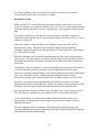
The first number that comes to mind when talking about NTSC video is 525, the number
of horizontal stripes or scan lines drawn across the screen to construct the picture. The
28
scan lines are drawn as follows: 240* odd lines of picture information, 22* black lines,
240* even lines of picture information, 23* black lines. This is all repeated 30+ times a
second. The "black" lines contain information to keep the TV set scanning in
synchronism with the broadcast and allow time to get the electron beam back to the top of
the screen. They also contain coded information for closed caption text, commercial
identification and tracking, etc.
To create picture detail the electron beam makes tiny dots and dashes as it draws each
scan line. With 525 scan lines redrawn 30 times a second, millions of these dots and
dashes are needed every second. Electronically the NTSC broadcast video signal uses
frequencies up to 4.2 million cycles per second (MHz). Every cycle has an "up" that
represents a dark dot and a "down" that represents a light dot, thus 4.2 MHz can represent
8.4 million dots per second. To make coarser detail (dashes) the cycles are stretched out,
or represent lower frequencies. To make shades of gray the ups and downs are not so
high or deep. At this rate we can get a maximum of 533 dots per scan line. Not all of
these dots can be used for picture detail. In the early days of TV, the last seventeen
percent of each scan line had to be made black to hold synchronizing information and to
get the electron beam back to the left side to draw the next line. The remaining 83% of a
scan line holds 442 dots which is the maximum amount of horizontal detail we can put
into the picture.
Applying the circle rule, 330 of the dots fit across the largest circle that in turn fits in the
screen, thus giving the commonly published horizontal resolution of 330 lines for NTSC
broadcast TV programs. While the TV set may be capable of higher resolution (making
even smaller sized dots as needed for the best playback of DVD) the most resolution that
will be seen for received TV broadcasts is 330 lines.
Trying to broadcast more dots on a scan line would make parts of the video signal go
above 4.2 MHz and interfere with the sound portion of the TV channel which is
positioned at 4.5 MHz. The circuits (filters) that make sure the video signal does not
contaminate the audio signal unfortunately usually weaken the portion of the valid video
signal near 4.2 MHz. This makes it impossible to get the tiniest details that could be
broadcast to be really black or white; they end up being dark gray and light gray instead.
Technical term: Bandwidth -- The difference between the maximum and the minimum
frequencies of a band of frequencies that a circuit or system can pass with no more than
50% attenuation (weakening). If the bandwidth does not start at zero, two of the
parameters lower bound, upper bound, and width, must be specified.
Some sources state that 4.0 MHz is the maximum usable video frequency, since typical
video amplifiers in the early days couldn't get up to 4.2 MHz while still cutting off by 4.5
MHz. This permits an even 8 million dots per second or 508 dots per scan line. Also, if
the transmitting electronics weakened the 4.2 MHz portions of the video signal by 50%
and the receiving electronics weakened it another 50%, each set of electronics by itself
meeting the definition of a 4.2 MHz bandwidth, by the time the picture got to the screen,
the tiniest dots could still be too much grayed out to be distinguished.
29
* Numbers marked with an asterisk are approximate. These numbers and also the exact
location of the 525'th line may vary slightly depending on the subject matter and with the
make and model of equipment used.
+ To make this text clearer, numbers marked with a plus sign have been rounded from
actual precise values that have lots of decimal places.
For NTSC interlaced video, the horizontal resolution is 80 (79) times the video circuitry
bandwidth in megahertz, for example 3.0 MHz which is typical for a cheap TV allows
about 240 lines of resolution.
30
APPENDIX B – Detailed descriptions White Balance
Parts of this Appendix are taken from the web site
http://www.photoxels.com/tutorial_white-balance.html
If you come from the world of films or single lens reflex cameras, you may remember
using filters to correct for incandescent or fluorescent lighting. Most people don't bother
and their indoors pictures invariably come out with a yellow/orange or bluish cast. In the
digital world, these correction filters are no longer necessary, replaced by a feature found
in most -- even the entry-level -- digital cameras called, "White Balance."
Light Color Temperature
The reason that pictures turn out with a yellow/orange cast in incandescent (tungsten)
lighting and bluish in fluorescent lighting is because light has a color temperature. A low
color temperature shifts light toward the red; a high color temperature shifts light toward
the blue. Different light sources emit light at different color temperatures, and thus the
color cast.
By using an orange or blue filter, we absorb the orange and blue light to correct for the
"imbalance" -- the net effect is a shift in the color temperature.
Manual White Balance
This is where the concept of "White Balance" comes in. If we can tell the camera which
object in the room is white and supposed to come out white in the picture, the camera can
calculate the difference between the current color temperature of that object and the
correct color temperature of a white object. And then shift all colors by that difference.
Most advanced digital cameras provide the feature to manually set the white balance. By
pointing the camera at a white or gray card (angled so that it is reflecting light from the
room) as a neutral reference, filling the screen completely with it, then pressing the White
Balance button (or set it in the menu), the camera does its White Balance calculation.
From then on, any picture taken will have its color temperature shifted appropriately.
A sophisticated user of a Ken-A-Vision camera, might try placing a white card in front of
the camera just before taking an image, and the camera will undergo self white balance
under the extant lights, or in those cameras with manual re-setting of white balance, the
color temperature can be adjusted for.
Automatic and Manual Re-setting White Balance
All Ken-A-Vision cameras provide a preset White Balance setting which works well in
most lighting situations including Tungsten, Fluorescent, Cloudy, Sunny, etc.
31
Some Ken-A-Vision cameras also allow the user to adjust the White Balance using the
Applied Vision Software This is accessed by clicking on the three tools icon (on the live
image screen), then within the ‘Video’ box that appears, click on the camera icon in left
corner of box. The tab which will give the user access to the White Balance button
varies among different cameras. Note in Applied Vision 3 (coming in spring 2007) the
image will remain on screen so that changes in settings can be seen as adjustments are
made.
Note – Manual re-set is not available on all KAV cameras – It is available on the camera
drives used in the 7200UM, 7890U, 7890UM, , T-1252, T-1754, T-1952, T-1954, , 1401
KRM/KEM.
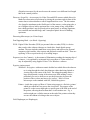
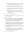
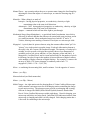
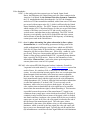
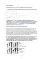
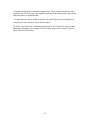
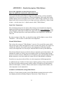
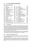
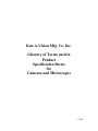
White Balance
AWB
Preset WB = Tungsten
In the above example, the picture on the left is taken with the camera set to Auto White
Balance. The indoor lighting is by two ordinary incandescent (tungsten) bulbs from the
ceiling. It's not bad, but the fan should really be white. By adjusting the White Balance,
the color temperature can be adjusted for by most users.
Usually the preset White Balance setting is appropriate for most lighting situations.
Additional ways to make Color Temperature adjustments
When you save an image on a Ken-A-Vision camera, you are saving it the way the image
sensor sees it after pre-set white balancing has occurred. With single images, Ken-AVision cameras default to a JPEG format, to which after the picture is taken, the
brightness, contrast and color intensity can be corrected within limits using the buttons on
the palette. Undo your change and try again, ad infinitum, in as fine an increment as you
wish, until you obtain perfect color balance. The image may also be exported to any
software that allows manipulation of the image, and even more severe brightness,
contrast, and color changes may be made.
32