1
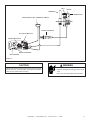
R
COLUMBIA BAY INSERT
DIRECT VENT GAS APPLIANCE
Owner’s Manual
Installation and Operation
Model:
COLBAY-INS
Tested and
Listed by
Portland
Oregon USA
O-T L
C
US
OMNI-Test Laboratories, Inc.
CAUTION
DO NOT DISCARD THIS MANUAL
• Important operating
and maintenance
instructions included.
• Read, understand and follow
these instructions for safe
installation and operation.
WARNING: If the information in these
instructions is not followed exactly, a fire
or explosion may result causing property
damage, personal injury, or death.
• Do not store or use gasoline or other flammable vapors and liquids in the vicinity of
this or any other appliance.
• What to do if you smell gas
- Do not try to light any appliance.
- Do not touch any electrical switch. Do not
use any phone in your building.
- Immediately call your gas supplier from a
neighbor’s phone. Follow the gas supplier’s instructions.
- If you cannot reach your gas supplier, call
the fire department.
• Installation and service must be performed
by a qualified installer, service agency, or the
gas supplier.
Installation and service of this appliance should be
performed by qualified personnel. Hearth & Home
Technologies suggests NFI certified or factory trained
professionals, or technicians supervised by an NFI
certified professional.
• Leave this manual with
party responsible for use
and operation.
D
DI O N
SC OT
AR
D
WARNING
HOT SURFACES!
Glass and other surfaces are hot during
operation AND cool down.
Hot glass will cause burns.
• Do not touch glass until it is cooled
• NEVER allow children to touch glass
• Keep children away
• CAREFULLY SUPERVISE children in same room as
fireplace.
• Alert children and adults to hazards of high temperatures.
High temperatures may ignite clothing or other flammable
materials.
• Keep clothing, furniture, draperies and other flammable
materials away.
In the Commonwealth of Massachusetts:
• installation must be performed by a licensed plumber or gas
fitter;
• a CO detector shall be installed in the room where the
appliance is installed.
This appliance may be installed as an OEM installation in manufactured
home (USA only) or mobile home and must be installed in accordance
with the manufacturer's instructions and the manufactured home construction and safety standard, Title 24 CFR, Part 3280 or Standard for
Installation in Mobile Homes, CAN/CSA Z240MH.
This appliance is only for use with the type(s) of gas indicated on the
rating plate.
Quadra-Fire • Columbia Bay Insert • 7002-109 Rev. H • 10/08
1
and Welcome to the Quadra-Fire Family!
Hearth & Home Technologies welcomes you to our tradition of excellence! In choosing a Quadra-Fire appliance,
you have our assurance of commitment to quality, durability, and performance.
is meticulously fabricated and gold and nickel surfaces
are hand-finished for lasting beauty and enjoyment. Our
pledge to quality is completed as each model undergoes
a quality control inspection. From design, to fabrication,
to shipping: Our guarantee of quality is more than a word,
it’s Quadra-Fire tradition, and we proudly back this tradition
with a Limited Lifetime Warranty.
This commitment begins with our research of the market,
including ‘Voice of the Customer’ contacts, ensuring we
make products that will satisfy your needs. Our Research
and Development facility then employs the world’s most
advanced technology to achieve the optimum operation of
our stoves, inserts and fireplaces. And yet we are old-fashioned when it comes to craftsmanship. Each appliance
We wish you and your family many years of enjoyment in
the warmth and comfort of your hearth appliance. Thank
you for choosing Quadra-Fire.
SAMPLE OF SERIAL NUMBER / SAFETY LABEL
LOCATION: HANGING ON A CHAIN ON BACK OF APPLIANCE
Test Lab &
Report No.
Beaverton
Oregon USA
Tested and
Listed by
C
SERIAL
NO.
Serial Number
XXX
R
OMNI- Test Laboratories, Inc.
Report No. / Rapport Numero
061-S-63-5
Model Name
MODEL: XXXXXXX
VENTED GAS APPLIANCE
NOT FOR USE WITH SOLID FUEL
FAN TYPE VENTED CIRCULATOR Blower Electrical Rating115 V., 1.5 Amps, 60 Hz, 150 Watts
P.4.1-02 Canada Minimum Pipe 69% NG / 71% LP
APPROVED FOR CANADA AND USA TO:
ANSI Z21.88b-2003 / CSA 2.33b-2003 Vented Gas Fireplace Heate r, and applicable sections of UL307b Gas Burning
Heating Appliances for Manufactured Homes and Recreational Vehicles, CAN/CG A 2.17-M91 “Gas Fired Appliances
for use at High Altitudes.”
This appliance is manufactured for operation with Natural Gas. For conversion to propane the Manufacturer’s kit
provided with the stove must be used in conjuntion with the instructions in the owner's manual.
This vented gas fireplace heater is not for use with air filters.
This appliance may be installed in a bedroom or bedsitting room; in Canada remote thermostat installation is
required.
For use with Natural Gas
"0-2000’
30,000
22,500
36
4.5”
7.0”
3.5”
82.5%
71%
Input Rate on “HI” (BTU/Hr)
Input Rate on “LO” (BTU/Hr)
Main Burner Orifice (DMS)
Minimum Inlet Pressure (Inches W.C.)
Maximum Inlet Pressure (Inches W.C.)
Manifold Pressure on “HI” (Inches W.C.)
Efficiency up to
AFUE
For use with Propane
"0-2000’
28,000
22,650
52
11”
14”
10”
81%
72.5%
This appliance equipped for altitudes 0-2000’ (0-610m) in USA; and in Canada for altitudes of 0-4500’ (0-1370m). In USA for
Altitudes above 2000’, the vent configuration, orifice, or combination of both may need to be changed. See Owner’s Manual for
information on making these changes.
This appliance must be installed in accordance with local codes, if any (and Commonwealth of Massachusetts approved); if
none, follow The National Fuel Gas Code,ANSI Z223.1 and NFPA 54; or Canadian Installation Codes CAN/CGA-B149.
NOTE: Have the gas supply line installed in accordance with local building codes by a qualified installer approved and/or
licensed as required by the locality. (In the Commonwealth of Massachusetts, installation must be performed by a licensed
plumber or gas fitter.)
MINIMUM CLEARANCES TO COMBUSTIBLES
Manufactured by:
DO NOT REMOVE THIS LABE
L
MADE IN U.S.A.
Date of Manufacture / Date du Manufacturier
2005
2006
2007
Jan
Feb
Mar
Apr
May
Jun
Jul
Aug
Sep
Oct
Nov
Dec
7031-221
2
Quadra-Fire • Columbia Bay Insert • 7002-109 Rev. H • 10/08
Manufactured
Date
Table of Contents
1 Listing and Code Approvals
A.
B.
C.
D.
E.
F.
G.
8 Appliance Setup
Appliance Certification . . . . . . . . . . . . . . . . . . . . . . . . . . . .
Glass Specifications . . . . . . . . . . . . . . . . . . . . . . . . . . . . . .
BTU Specifications . . . . . . . . . . . . . . . . . . . . . . . . . . . . . . .
High Altitude Installations . . . . . . . . . . . . . . . . . . . . . . . . . .
Non-Combustible Materials Specification. . . . . . . . . . . . . .
Combustible Materials Specification . . . . . . . . . . . . . . . . .
Electrical Codes . . . . . . . . . . . . . . . . . . . . . . . . . . . . . . . . .
4
4
4
4
4
4
4
2 Getting Started
A. Design and Installation Considerations . . . . . . . . . . . . . . . 5
B. Tools and Supplies Needed . . . . . . . . . . . . . . . . . . . . . . . . 5
C. Inspect Appliance and Components . . . . . . . . . . . . . . . . . . 5
A.
B.
C.
D.
E.
F.
G.
H.
I.
J.
Remove Shipping Materials . . . . . . . . . . . . . . . . . . . . . . .
Accessories . . . . . . . . . . . . . . . . . . . . . . . . . . . . . . . . . . .
Door Crown Installation . . . . . . . . . . . . . . . . . . . . . . . . . .
Grille Installation . . . . . . . . . . . . . . . . . . . . . . . . . . . . . . . .
Panel Set Installation . . . . . . . . . . . . . . . . . . . . . . . . . . . .
Brick Installation . . . . . . . . . . . . . . . . . . . . . . . . . . . . . . . .
Positioning the Logs . . . . . . . . . . . . . . . . . . . . . . . . . . . . .
Mineral Wool . . . . . . . . . . . . . . . . . . . . . . . . . . . . . . . . . .
Blower Installation . . . . . . . . . . . . . . . . . . . . . . . . . . . . . .
Air Shutter Adjustment . . . . . . . . . . . . . . . . . . . . . . . . . . .
16
16
16
17
17
18
19
20
20
22
9 Operating Instructions
A. Selecting Appliance Location . . . . . . . . . . . . . . . . . . . . . . . 6
B. Clearances to Combustibles . . . . . . . . . . . . . . . . . . . . . . . 6
A.
B.
C.
D.
4 Termination Locations
10 Troubleshooting
A. Vent Termination Minimum Clearances . . . . . . . . . . . . . . . 7
A. Standing Pilot Ignition System . . . . . . . . . . . . . . . . . . . . . 26
5 Vent Information
11 Maintaining and Servicing Appliance
A. Venting and Installation . . . . . . . . . . . . . . . . . . . . . . . . . . . 8
A. Glass Replacement . . . . . . . . . . . . . . . . . . . . . . . . . . . . . 28
B. Maintenance Tasks. . . . . . . . . . . . . . . . . . . . . . . . . . . . . . 29
3 Framing and Clearances
Before Lighting Appliance. . . . . . . . . . . . . . . . . . . . . . . . .
Lighting Appliance . . . . . . . . . . . . . . . . . . . . . . . . . . . . . .
After Appliance is Lit . . . . . . . . . . . . . . . . . . . . . . . . . . . . .
Frequently Asked Questions . . . . . . . . . . . . . . . . . . . . . .
23
24
25
25
6 Gas Information
A.
B.
C.
D.
E.
Fuel Conversions . . . . . . . . . . . . . . . . . . . . . . . . . . . . . . . 10
Converting to LP Gas . . . . . . . . . . . . . . . . . . . . . . . . . . . . 10
Valve Regulator Replacement . . . . . . . . . . . . . . . . . . . . . .11
Gas Pressures . . . . . . . . . . . . . . . . . . . . . . . . . . . . . . . . . 12
Gas Connection . . . . . . . . . . . . . . . . . . . . . . . . . . . . . . . . 12
12 Reference Materials
A.
B.
C.
D.
E.
Appliance Dimension Diagram . . . . . . . . . . . . . . . . . . . . .
Vent Components List . . . . . . . . . . . . . . . . . . . . . . . . . . .
Service Parts List . . . . . . . . . . . . . . . . . . . . . . . . . . . . . .
Limited Lifetime Warranty . . . . . . . . . . . . . . . . . . . . . . . . .
Contact Information . . . . . . . . . . . . . . . . . . . . . . . . . . . . .
30
31
33
35
37
7 Electrical Information
A. Recommendation for Wire . . . . . . . . . . . . . . . . . . . . . . . . 14
B. Connecting to the Appliance. . . . . . . . . . . . . . . . . . . . . . . 14
C. Standing Pilot Ignition System Wiring . . . . . . . . . . . . . . . 14
= Contains updated information.
Quadra-Fire • Columbia Bay Insert • 7002-109 Rev. H • 10/08
3
1
Listing and Code Approvals
A. Appliance Certification
D. High Altitude Installations
MODELS: Columbia Bay Insert
LABORATORY: Omni Test Laboratories, Inc. 061-S-30-5
TYPE: Direct Vent Gas Fireplace Heater
STANDARD: ANSI Z21.88-2002 • CSA 2.33-2002 • UL307B
CAN/CBA 2.17-M91
This product is listed to ANSI standards for “Vented Gas
Appliance Heaters” and applicable sections of “Gas Burning Heating Appliances for Manufactured Homes and
Recreational Vehicles”, and “Gas Fired Appliances for
Use at High Altitudes”.
Manufactured Home or Mobile Home installation may
occur only after the home is site located and must conform
with the Manufactured Home Construction and Safety
Standard, Title 24 CFR, Part 3280, or, when such a
standard is not applicable, the Standard for Manufactured
Home Installations, ANSI/NCSBCS A225.1, or Standard
for Gas Equipped Recreational Vehicles and Mobile
Housing, CSA Z240.4.
When installed, the appliance must be electrically grounded
in accordance with local codes or, in the absence of local
codes, with the National Electrical Code, ANSI/NFPA 70,
or the Canadian Electrical Code, CSA C22.1.
B. Glass Specifications
This appliance is equipped with 5 mm ceramic glass.
Replace glass only with 5 mm ceramic glass. Please contact your dealer for replacement glass.
Note: This installation must conform with local codes. In the
absence of local codes you must comply with the National
Fuel Gas Code, ANSI Z223.1-latest edition in the U.S.A. and
the CAN/CGA B149 Installation Codes in Canada.
C. BTU Specifications
Omni-Test Laboratories, Inc. listed gas appliances are
tested and approved without requiring changes for
elevations from 0 to 2000 feet in the U.S.A. and 0 to 4500
feet in Canada.
When installing this appliance at an elevation above 2000
feet, it may be necessary to decrease the input rating
by changing the existing burner orifice to a smaller size.
Input rate should be reduced by 4% for each 1000 feet
above a 2000 foot elevation in the U.S.A. If the heating
value of the gas has been reduced, these rules do not
apply. To identify the proper orifice size, check with the
local gas utility.
If installing this appliance at an elevation above 4500 feet
(in Canada), check with local authorities.
WARNING
Do NOT use this appliance if any part has been under water.
Immediately call a qualified service technician to inspect the
appliance and to replace any part of the control system and
any gas control which has been under water.
E. Non-Combustible Materials Specification
Material which will not ignite and burn. Such materials are
those consisting entirely of steel, iron, brick, tile, concrete,
slate, glass or plasters, or any combination thereof.
Materials that are reported as passing ASTM E 136,
Standard Test Method for Behavior of Materials in a
Vertical Tube Furnace at 750ºC, shall be considered
non-combustible materials.
F. Combustible Materials Specification
Materials made of or surfaced with wood, compressed
paper, plant fibers, plastics, or other material that can ignite and burn, whether flame proofed or not, or whether
plastered or unplastered shall be considered combustible
materials.
G. Electrical Codes
(US or Canada)
Maximum
Input
BTU/h
Minimum
Input
BTU/h
Orifice
Size
(DMS)
*Steady
State
Efficiency %
**P.4
%
Columbia Bay
Insert (NG)
30,000
20,000
.106
83.07
67.15
Columbia Bay
Insert (LP)
30,000
23,000
.063
84.66
70.32
Model
*Maximum Vent Blower On
**Canada Only
4
NOTICE: This appliance must be electrically wired and
grounded in accordance with local codes or, in the absence
of local codes, with National Electric Code ANSI/NFPA
70-latest edition or the Canadian Electric Code CSA
C22.1.
• A 110-120 VAC circuit for this product must be protected
with ground-fault circuit-interrupter protection, in compliance
with the applicable electrical codes, when it is installed in
locations such as in bathrooms or near sinks.
Quadra-Fire • Columbia Bay Insert • 7002-109 Rev. H • 10/08
2
Getting Started
A. Design and Installation Considerations
C. Inspect Appliance and Components
Quadra-Fire direct vent gas appliances are designed to
operate with all combustion air siphoned from outside of
the building and all exhaust gases expelled to the outside.
No additional outside air source is required.
WARNING
Inspect appliance and components for damage.
Damaged parts may impair safe operation.
• Do NOT install damaged components.
• Do NOT install incomplete components.
• Do NOT install substitute components.
Report damaged parts to dealer.
CAUTION
Check building codes prior to installation.
• Installation MUST comply with local, regional, state and
national codes and regulations.
• Consult local building, fire officials or authorities having jurisdiction about restrictions, installation inspection, and permits.
When planning an appliance installation, it’s necessary to
determine the following information before installing:
• Where the appliance is to be installed.
• The vent system configuration to be used.
• Carefully remove the appliance and components from
the packaging.
• Remove cast door and glass, and set aside on protective
surface.
• Remove log set and component pack from firebox.
• Report to your dealer any parts damaged in shipment,
particularly the condition of the glass.
• Read all of the instructions before starting the installation. Follow these instructions carefully during the
installation to ensure maximum safety and benefit.
• Gas supply piping.
• Electrical wiring.
• Framing and finishing details.
• Whether optional accessories—devices such as a fan,
wall switch, or remote control—are desired.
WARNING
Hearth & Home Technologies disclaims any
responsibility for, and the warranty will be voided
by, the following actions:
WARNING
Keep appliance dry.
• Mold or rust may cause odors.
• Water may damage controls.
B. Tools and Supplies Needed
Before beginning the installation be sure that the following
tools and building supplies are available.
• Installation and use of any damaged appliance or vent
system component.
• Modification of the appliance or vent system.
• Installation other than as instructed by Hearth & Home
Technologies.
• Improper positioning of the gas logs or the glass door.
• Installation and/or use of any component part not approved
by Hearth & Home Technologies.
Any such action may cause a fire hazard.
Reciprocating saw
Framing material
Pliers
Hi temp caulking material
Hammer
Gloves
Phillips screwdriver
Framing square
Flat blade screwdriver
Electric drill and bits (1/4 in.)
Plumb line
Safety glasses
Level
Wrenches
Ratchets/Sockets
Allen Wrench Set
Manometer
Voltmeter
Tape measure
1/2 - 3/4 inch length, #6 or #8 Self-drilling screws
One 1/4 inch female connection (for optional fan)
Noncorrosive leak check solution or combustible gas detector
Quadra-Fire • Columbia Bay Insert • 7002-109 Rev. H • 10/08
5
3
Framing and Clearances
WARNING
Note:
• Illustrations reflect typical installations and are FOR
DESIGN PURPOSES ONLY.
• Illustrations/diagrams are not drawn to scale.
• Actual installation may vary due to individual design
preference.
Fire Risk
Provide adequate clearance:
• Around air openings
• To combustibles
• For service access
Locate appliance away from traffic areas.
A. Selecting Appliance Location
When selecting a location for your appliance it is important to
consider the required clearances to walls (see figure 3.1).
NOTE: For actual appliance dimensions refer to Section 12.
B. Clearances to Combustibles
To 8 in. (203 mm ) Deep mantel:
14 in. (356 mm) From top of insert
A
B
D
SIDE WALL
C
16 in. (406 mm)
1-1/2 in. (38 mm)
HEARTH
Model
Columbia Bay Insert
A
B
C
D
Inches
13
10
10
7
Millimeters
330
254
254
178
Underneath bottom of appliance to combustibles: 3/8 in. (10 mm)
16 in. (406 mm) front floor protection required 0 in. to 1-1/2 in. (38 mm) below bottom of appliance. (1/2 in. of "k" = .84)
No floor protection needed if 1-1/2 in. (38 mm) or greater from bottom of appliance.
Figure 3.1
6
Quadra-Fire • Columbia Bay Insert • 7002-109 Rev. H • 10/08
4
Termination Locations
A. Vent Termination Minimum Clearances
GAS OR WOOD
TERMINATION
Figure 4.1 specifies minimum vent heights for various
pitched roofs.
18 IN.
GAS
TERMINATION
2 FEET
(MINIMUM) TO
PERPENDICULAR
WALL (GAS ONLY)
HORIZONTAL
OVERHANG
A
2 FT.
MIN.
20 INCHES MIN.
VERTICAL
WALL
LOWEST
DISCHARGE
OPENING
GAS DIRECT VENT
TERMINATION CAP
X
12
ROOF PITCH
IS X/ 12
H (MIN.) - MINIMUM HEIGHT FROM ROOF
TO LOWEST DISCHARGE OPENING
A
Gas Termination
Wood & Fuel Oil Termination
6 in.
20 in.
Figure 4.2 Multiple Vertical Termination
Roof Pitch
H (Min.) Ft.
Flat to 6/12...........................................................1.0*
Over 6/12 to 7/12 .................................................1.25*
Over 7/12 to 8/12 .................................................1.5*
Over 8/12 to 9/12 .................................................2.0*
Over 9/12 to 10/12 ...............................................2.5*
Over 10/12 to 11/12 .............................................3.25
Over 11/12 to 12/12 .............................................4.0
Over 12/12 to 14/12 .............................................5.0
Over 14/12 to 16/12 .............................................6.0
Over 16/12 to 18/12 .............................................7.0
Over 18/12 to 20/12 .............................................7.5
Over 20/12 to 21/12 .............................................8.0
WARNING
Fire Risk.
Asphyxiation Risk.
• Terminations MUST meet minimum clearances.
• Exhaust gases are hot.
• Nearby vents may draw fumes into house.
* 3 foot minimum in snow regions
Figure 4.1 Minimum height from roof to lowest discharge
opening
Quadra-Fire • Columbia Bay Insert • 7002-109 Rev. H • 10/08
7
5
Vent Information
A. Venting and Installation
Tools and supplies needed: Pliers; Phillips screwdriver;
Tape measure; Level; Electrical drill and bits; Square; and
High Temperature Sealant Material.
Note: Quadra-Fire gas inserts are designed for recessed
installations into solid fuel Masonry or Factory Built Noncombustible fireplaces that have been installed in accordance
with the National, Provincial, State and Local building codes.
Note: Shipping brackets used to attach appliance to pallet can
be used as leveling legs when attached to back of appliance.
The damper of the masonry or factory-built chimney must
be removed or fixed open to install the appliance.
Note: In the Commonwealth of Massachusetts, the word
damper shall be replaced with the words flue restrictor.
Minimum fireplace opening requirements are shown on
section 12 of this manual. The firebrick (refractory) can
be removed from a factory built fireplace in order to gain
minimum gas insert opening requirements.
Install the 3 in. (76 mm) flexible vent pipes down through
the chimney. Attach and secure the bottom ends of the
flex pipes to the starting collar bracket with set screws on
each collar. Attach the labeled pipe to the exhaust collar
on the starter collar bracket.
Place the insert on the hearth and carefully slide it into the
fireplace. Be sure the gas line enters the heater through
the gas access opening and that the electrical cord is
extending out the right. (Cord may be re-routed to the left
if necessary. A notch will be needed in the trim piece for
the cord restraint.)
Position any excess flex vent pipe back up into the
chimney.
Install LP conversion, brick set and panel and trim at
this point in accordance with your installation plans. See
instructions in this manual to do so.
Slide the unit back into the fireplace.
Attach transition assembly to the appliance. Rotate transition assembly latches and lock with the 7/16 in. wrench.
Before installing the 3 in. (76 mm) flex vent pipe, mark or
label the exhaust pipe at both ends.
Attach the pipe-to-cap adapter to the termination cap and
to the top of the flexible vent pipe and set the cap in place
at the top of the chimney. Attach the labeled vent pipe to
the labeled collar on the termination.
AIR INTAKE
TERMINATION CAP
Figure 5.2
ADAPTER
High Temperature Sealant Material. Sealants that will
withstand high temperatures (at least 350 degrees Fahrenheit); General Electric RTV103 (Black), or equivalent.
Rutland, Inc. Fireplace Mortar #63, or equivalent; Dow
Corning 732 or equivalent.
FLEX PIPE
Note: To avoid down drafts and/or cold air problems, it is
recommended to seal off the area between the termination
cap and the top of the solid-fuel chimney opening into which
the vent cap has been installed.
TRANSITION ASSEMBLY
SHIPPING BRACKETS ATTACHED
TO REAR OF APPLIANCE FOR
USE AS LEVELING LEGS
Figure 5.1
8
Note: the metal floor of the solid fuel firebox may be removed
to facilitate the installation of the insert. Clearance to
combustible material under the insert is 3/8 in. (1 mm). You
must use the leveling legs to raise the insert a minimum of
3/8 in. (10 mm) if the insert is to sit on combustible material.
The side walls and top structure of the firebox may not be
altered with the exception of removable baffles and dampers.
The original fireplace may never be returned to solid fuel in
this condition.
Quadra-Fire • Columbia Bay Insert • 7002-109 Rev. H • 10/08
THIS OPTION SHOWS THE AIR INLET
TERMINATING IN THE CHIMNEY.
TERMINATION CAP
ADAPTOR
EXHAUST
AIR VENT
PIPE
V=10 FT. (3 M) MINIMUM
40 FT. (12 M) MAXIMUM
INSULATION
INLET AIR
VENT PIPE
Note: Insulation is not included with the venting kit.
Figure 5.3
WARNING
Fire Hazard.
Asphyxiation Risk.
• The exhaust pipe must only be connected to
the exhaust starting collar of the unit and the
center collar of the termination cap.
• The inlet air pipe must only be connected to the
inlet air collar of the unit and either attached
to the inlet air collar of the termination cap or
terminated in the chimney.
Quadra-Fire • Columbia Bay Insert • 7002-109 Rev. H • 10/08
9
6
Gas Information
A. Fuel Conversions
Before making gas connections ensure that appliance being installed is compatible with the available gas type.
With a 5/8 in. wrench remove the orifice retaining nut.
Replace with the appropriate orifice (.063 LP / .106 NG).
Any natural or propane gas conversions necessary to
meet the appliance and locality needs must be made by
a qualified technician using Hearth & Home Technologies
specified and approved parts.
B. Converting to LP Gas
Note: Gas conversions should only be performed by a
qualified service person, and/or where required by state
and local codes, licensed installer/service technician. In
the Commonwealth of Massachusetts, installation must be
performed by a licensed plumber or gas fitter.
Figure 6.2
Kit contents: Replacement orifice; replacement pilot
injector; valve regulator; conversion label.
Remove the pilot hood and set aside.
Tools required: Power drill (a 90° handle is helpful); #2
Phillips bit; 5/32 in. (4 mm) Allen wrench; 5/8 in. (16 mm)
open end wrench.
Remove logs and refractory support covers from the
burner pan. Remove the two screws that secure the
burner pan to the burner support with the screwdriver. Lift
burner up and out of the firebox opening.
Figure 6.3
Note: Do not remove retaining clip from the pilot hood.
Using a 5/32 in. (4 mm) Allen wrench, remove the pilot
injector and replace with an appropriate injector (#35 LP
/ #62 NG).
Figure 6.1
Figure 6.4
Reinstall burner and secure with the two screws previously removed.
10
Quadra-Fire • Columbia Bay Insert • 7002-109 Rev. H • 10/08
C. Valve Regulator Replacement
Remove upper and lower back shield. Loosen the set collars on the extension rods with the 3/32 in. Allen wrench.
Remove the rods and adapter cap.
Turn control knob to the OFF position, ensure that gas
supply to the valve has been turned off. Using a Torx
TH20, or slotted screwdriver, remove the three pressure
regulator mounting screws (A), pressure regulator tower
(B), and diaphragm (C).
Ensure that the rubber gasket (D) is properly positioned
and install the new HI/LO pressure regulator assembly to
the valve using the new screws (E) supplied with the kit.
Tighten screws securely. (Reference torque = 25 in./lb.)
Install the enclosed identification label (F) to the valve
body where it can be seen.
Fill out the conversion label and attach it to the valve
cover.
E
A
B
D
C
F
Figure 6.6
Figure 6.5
WARNING
WARNING
Fire Risk.
Explosion Risk.
• Disconnect any electrical cords and turn
off gas supply to unit before proceeding if
converting fuel on an appliance already fully
installed.
Fire Risk.
Explosion Risk.
Gas Leak Risk.
• Rubber gasket must be seated properly on
valve face.
• Do no install a valve or regulator that has
been dropped.
WARNING
Fire Risk.
Explosion Risk.
• If the information in these instructions is
not followed exactly, a fire, explosion or
production of carbon monoxide may result
causing property damage, personal injury or
loss of life.
• The qualified service agency is responsible
for the proper installation of this conversion
kit. The installation is not proper and complete
until the operation of the converted appliance
is checked as specified in the manufacturer’s
instructions supplied with the kit.
Quadra-Fire • Columbia Bay Insert • 7002-109 Rev. H • 10/08
11
D. Gas Pressures
E. Gas Connection
Proper input pressures are required for optimum appliance performance. Gas line sizing requirements need to
be made following NFPA54.
WARNING
Fire Risk.
Explosion Hazard.
High pressure will damage valve.
• Disconnect gas supply piping BEFORE
pressure testing gas line at test pressures
above 1/2 psig.
• Close the manual shutoff valve BEFORE
pressure testing gas line at test pressures
equal to or less than 1/2 psig.
Note: Have the gas supply line installed in accordance
with local building codes, if any. If not, follow ANSI
223.1. Installation should be done by a qualified installer
approved and/or licensed as required by the locality. (In
the Commonwealth of Massachusetts installation must be
performed by a licensed plumber or gas fitter).
Note: A listed (and Commonwealth of Massachusetts approved) 1/2 inch (13 mm) T-handle manual shut-off valve and
flexible gas connector are connected to the 1/2 inch (13 mm)
control valve inlet.
• If substituting for these components, please consult
local codes for compliance.
WARNING
WARNING
Verify inlet pressures.
• High pressure may cause overfire condition.
• Low pressure may cause explosion.
• Verify minimum pressures when other
household gas appliances are operating.
Install regulator upstream of valve if line
pressure is greater than 1/2 psig.
Pressure requirements for appliance are shown in the
table below. Minimum pressures must be met when other
household gas appliances are operating.
Pressure
Natural Gas
Propane
Minimum inlet pressure
4.5 inches
w.c.
11.0 inches
w.c.
Maximum inlet gas pressure
7.0 inches
w.c.
14.0 inches
w.c.
Manifold pressure
3.5 inches
w.c.
10.0 inches
w.c.
If the pressure is not sufficient, ensure:
• The piping used is large enough.
Gas Leak Risk
• Support control when attaching pipe to
prevent bending gas line.
Note: The gap between supply piping and gas access hole
may be caulked with high temperature caulk or stuffed with
non-combustible, unfaced insulation to prevent cold air
infiltration.
Leak test all gas line joints and the gas control valve prior
to and after starting the appliance.
Before making the gas connection, ensure that the
appliance you are installing is designed for the type of
gas being supplied. This information can be found on the
ratings label under the appliance. If the appliance has
been converted to propane (LP), the valve cover should
have a label stating that the appliance has been converted
to propane.
Connect the gas line at the 3/8 in. (10 mm) pipe connector
on the valve at the back of appliance. We recommend
connecting the appliance with an approved flex gas line.
If flex gas lines are not approved in your area, you must
connect a hard pipe to the gas hookup.
• The supply regulator is adequately adjusted.
You must supply a manual shut-off valve in a visible
location within 3 ft. (914 mm) of the appliance.
• That the total gas load for the residence does not
exceed the amount supplied.
Ensure that gas line does not come in contact with outer
wrap of appliance. Follow local codes.
The supply regulator (the regulator that attaches directly
to the residence inlet or to the propane tank) should supply
gas at the suggested input pressure listed above. Contact
the local gas supplier if the regulator is at an improper
pressure.
Incoming gas line should be piped into the valve
compartment and connected to the 1/2 inch connection
on the manual shutoff valve.
12
Quadra-Fire • Columbia Bay Insert • 7002-109 Rev. H • 10/08
WARNING
Fire or Explosion Hazard
•
•
•
•
Gas buildup during line purge may ignite.
Purge should be performed by qualified technician.
Ensure adequate ventilation.
Ensure there are no ignition sources such as
sparks or open flames.
• A small amount of air will be in the gas supply lines.
When first lighting appliance it will take a short time for
air to purge from lines. When purging is complete the
appliance will light and operate normally.
Air only needs to be purged again if gas valve has been
turned to the OFF position.
WARNING
CHECK FOR GAS LEAKS
Explosion Risk
Fire Risk
Asphyxiation Risk
• Check all fittings and connections.
• Do not use open flame.
• After the gas line installation is complete, all
connections must be tightened and checked
for leaks with a commercially-available,
non-corrosive leak check solution. Be sure
to rinse off all leak check solution following
testing.
Fittings and connections may have loosened
during shipping and handling.
WARNING
Fire hazard.
Do NOT change the valve settings.
• This valve has been preset at the factory.
• Changing valve settings may result in fire
hazard or bodily injury.
HIGH ALTITUDE INSTALLATIONS
Omni-Test Laboratories, Inc. listed gas appliances are tested
and approved without requiring changes for elevations from
0 to 2000 feet in the U.S.A. and 0 to 4500 feet in Canada.
When installing this appliance at an elevation above 2000
feet, it may be necessary to decrease the input rating by
changing the existing burner orifice to a smaller size. Input
rate should be reduced by 4% for each 1000 feet above a
2000 foot elevation in the U.S.A. If the heating value of the
gas has been reduced, these rules do not apply. To identify
the proper orifice size, check with the local gas utility.
If installing this appliance at an elevation above 4500 feet
(in Canada), check with local authorities.
Quadra-Fire • Columbia Bay Insert • 7002-109 Rev. H • 10/08
13
7
Electrical Information
A. Recommendation for Wire
See Figure 7.1 for recommended maximum lead length
(two wire) when using wall thermostat/switch.
NOTE: This appliance must be electrically wired and grounded
in accordance with local codes or, in the absence of local
codes, with National Electric Code ANSI/NFPA 70-latest
edition or the Canadian Electric Code, CSA C221.1.
• A 110-120 VAC circuit for this product must be protected
with ground-fault circuit-interrupter protection, in
compliance with the applicable electrical codes, when
it is installed in locations such as in bathrooms or near
sinks.
Do not connect this appliance to a thermostat serving
any other appliance.
Bedroom installation in Canada requires this appliance
to be connected to a thermostat.
WARNING
Shock hazard.
• This appliance is equipped with a three
pronged (grounding) plug for your protection
against shock hazard and should be plugged
directly into a properly
prop
grounded three prong
receptacle. Do not cut or remove the grounding prong from this plug.
C. Standing Pilot Ignition System Wiring
B. Connecting to the Appliance
1. This appliance may be used with a wall switch, wall
mounted thermostat and / or a remote control
2. If using thermostat, use one compatible with a millivolt
gas valve system.
This appliance DOES NOT require 110 VAC supply for
operation. A wiring diagram is shown in Figure 7.2 on the
next page.
This appliance is equipped with a millivolt control valve.
3. Follow parameters for locating thermostat (see individual thermostat instructions) to ensure proper operation
of appliance.
4. Use low resistance thermostat wire for wiring from
ignition system to the wall switch and thermostat.
5. Use the following chart for wire sizing.
Wire Size
Max. Length
16 gauge
65 feet
18 gauge
40 feet
20 gauge
25 feet
22 gauge
18 feet
Figure 7.1
6. Keep wire lengths as short as possible by removing
any excess wire length.
7. Low voltage and 110 VAC voltage cannot be shared
within the same wall box.
8. Ensure the thermostat is mounted level for accurate
readings.
9. The thermostat should be mounted on an inside wall
and not in direct line with the appliance convection air.
10. If the thermostat is located too close to the appliance, you may need to set the temperature setting
slightly higher to maintain the desired temperature
in your home.
14
Quadra-Fire • Columbia Bay Insert • 7002-109 Rev. H • 10/08
PILOT
IGNITOR
THERMOPILE
THERMOCOUPLE
ROCKER SWITCH / WALL THERMOSTAT / REMOTE
PUSH BUTTON IGNITOR
PILOT ADJUSTMENT CAP
VARIABLE REGULATOR
MANIFOLD PRESSURE
INLET PRESSURE
Figure 7.2
WARNING
CAUTION
Label all wires prior to disconnection when servicing controls.
Wiring errors can cause improper and dangerous operation.
Verify proper operation after servicing.
Shock hazard.
• Replace damaged wire with type 105º C rated
wire.
• Wire must have high temperature insulation.
Quadra-Fire • Columbia Bay Insert • 7002-109 Rev. H • 10/08
15
8
Appliance Setup
A. Remove Shipping Materials
Remove shipping materials from inside or underneath the
firebox.
Uninstall the existing crown by removing the four screws
on the back side of the door. Retain the screws.
B. Accessories
Install approved accessories per instructions included
with accessories. See Service Parts List for appropriate
accessories.
WARNING
Shock or fire risk.
Use ONLY optional accessories approved for
this appliance.
• Using non-listed accessories voids warranty.
• Using non-listed accessories may result in a
safety hazard.
• Only Hearth & Home Technologies approved
accessories may be used safely.
Figure 8.2
Use a flat-head screwdriver to pry the black crown free on
the right side. Remove the crown and discard.
C. Door Crown Installation
Open lower access panel. Pull out and unhook the two
spring latches on the bottom of the appliance that secure
the door.
Rotate the door forward approximately 1-1/2 in. (38 mm).
Holding the ashlip, lift the door up off of the stationary
latches and away from the appliance.
Figure 8.3
STATIONARY LATCHES
Carefully align the left side of the crown into place, and
wrap it across the face of door, finally snapping it into
place on the right hand side. Reinsert and tighten the
screws previously removed.
SPRING LOADED LATCHES
Figure 8.1
Figure 8.4
Note: Use a soft cloth and a window cleaning solution to clean
all fingerprint oils from the gold or nickel surface of crown
PRIOR to lighting the appliance.
16
Quadra-Fire • Columbia Bay Insert • 7002-109 Rev. H • 10/08
D. Grille Installation
Remove the door of appliance. Remove the four screws
(two at each end) holding grille in place. Lift up to
remove.
Assemble the trim with the two corner brackets provided.
Slide the assembled trim over the assembled panel set.
Figure 8.7
Slide the panel/trim down over the face of the unit, behind
the top, aligning the holes in the upper and lower, right
and left corners, and secure the panel and trim set to the
appliance with the attachment screws using four screws,
two per side.
Figure 8.5
Install the new grille by reversing removal instructions.
Note: Clean glass and gold or nickel with glass cleaner and a
soft cloth, wiping off all fingerprints prior to first fire to prevent
permanent staining.
SCREWS
E. Panel Set Installation
Included in kit: (2) Angle Brackets and set screws; (1)
3 piece Trim; (2) Side Panels; (1) Top Panel; (1) Switch
plug; and (8) screws.
Tools required: Philips head screwdriver.
Figure 8.8
Note: Remove the door from the insert before beginning the
panel installation.
Assemble the panel top to the panel sides with the screws
provided.
1 If you wish to place it on the control panel in the "Main
Burner" opening: Disconnect the "ON/OFF" switch
from the low voltage wire leads. Pull the wires through
the control panel, attach the wires to the "ON/OFF"
rocker switch and push the rocker switch into the
"Main Burner opening on control panel. Place the plug
provided in empty opening on the panel and trim.
OR
BACK OF TOP PANEL
SCREWS
BACK OF SIDE PANEL
Figure 8.6
Determine your desired placement of the rocker switch.
2. If you wish to place it on the side of appliance in the
knock out provided on the panel and trim: Carefully
reposition the wiring beneath the firebox to the RIGHT
side of appliance. Disconnect the "ON/OFF" switch from
the low voltage wire leads. Pull the wires through the
knockout plate on the panel and trim, attach the wires
to the "ON/OFF" rocker switch and push the rocker
switch into the opening on the panel and trim. Place
plug provided with panel set in empty switch location.
Install the power cord restraint found in the appliance component bag. (Cord is shipped exiting the right side of the
appliance, but can be routed in either direction.) A notch
will be needed in the trim piece for the cord restraint.
Slide the appliance back until the panel is tight to the fireplace.
Quadra-Fire • Columbia Bay Insert • 7002-109 Rev. H • 10/08
17
F. Brick Installation
Install baffle: Bring the front edge of the baffle up and
forward until the baffle rests on the baffle supports, as
shown.
Rest bottom of panel on shelf and push top into position.
Hold in place by bending brick clips over along front edge
of brick.
BAFFLE
SUPPORTS
BAFFLE
Figure 8.12
Install left brick panel in the same way by pushing in the
top and securing by bending clips at top and bottom.
Figure 8.9
Lift the baffle slightly and install the rear brick panel. Rest
baffle on rear brick panel.
BAFFLE
BRICK CLIP
REAR BRICK PANEL
Figure 8.10
Figure 8.13
Finished brick installment.
Install right brick panel.
BRICK CLIPS
Figure 8.14
Figure 8.11
18
Quadra-Fire • Columbia Bay Insert • 7002-109 Rev. H • 10/08
Install left log (#2) over locating pins on burner.
G. Positioning the Logs
While still breakable, the logs do not become fragile until
after the appliance is burned and they have cured. After
curing, any handling must be done with care as breakage
can easily occur.
Note: Logs have been designed to work specifically with the
burner of this appliance. Exact placement will ensure proper
operation of your gas appliance and reduce sooting.
Complete log installation.
Figure 8.18
Install right log (#3) in empty space on burner.
1
5
4
2
3
Figure 8.15
After installing brick, install rear log (#1) over locating pins
on log shelf, as shown.
Figure 8.19
Note: Locator pins are included in the log component
package.
Install "S" shaped log (#4) on pins on right and rear logs.
Figure 8.20
Figure 8.16
Install cover for refractory supports on left and right sides.
Left side
Figure 8.17
Install left twig (#5) on pin in left log resting just under "S"
shaped log.
Right side
Figure 8.21
Quadra-Fire • Columbia Bay Insert • 7002-109 Rev. H • 10/08
19
H. Mineral Wool
I. Blower Installation
WARNING
Explosion Risk.
• Follow ember placement instructions in manual.
• Do NOT place embers directly over burner ports.
• Replace ember material annually.
Improperly placed embers interferes with proper burner
operation.
Included in kit: Blower.
Tools required: Powered Phillips head screwdriver.
Turn off gas and disconnect appliance from electricity.
Remove logs and burner from appliance. Remove blower
access cover in bottom of firebox by removing the screws.
Retain screws for reassembly.
Place individual pieces of embers in front of and around the
gas log where they can be seen. Space them so that gas
can contact them on all sides. Avoid stacking the embers
on top of each other.
Figure 8.23
Disconnect wires from the snap disk on back of access
cover.
Figure 8.22
Note: Do not block gas ports.
Figure 8.24
Lift blower off of studs and pull through opening.
Figure 8.25
20
Quadra-Fire • Columbia Bay Insert • 7002-109 Rev. H • 10/08
Disconnect wires from the blower.
Remove grommet retainer from old blower and install on
new blower.
Figure 8.26
Figure 8.27
Installation is the reverse of removal.
F = 1/4 in. (6 mm) female spade
M = 1/4 in. (6 mm) male spade
RHEOSTAT
SNAP DISC
GRN
BLK
M
F
BLK
M F
WHT
WHT
R
BLK
F
BLK
M
BLK
M F
WHT
F
WHT
M
BLOWER
Figure 8.28 Blower Wiring Diagram
Quadra-Fire • Columbia Bay Insert • 7002-109 Rev. H • 10/08
21
J. Air Shutter Adjustment
The air shutter is used to fine-tune the flame as necessary.
The air shutter is shipped in the fully open position.
Allow the unit to operate 15-20 minutes before making any
adjustments to the air shutter. This will give the flame time
to reach its height and color before making adjustments.
The air shutter is located on the underside of the appliance,
on the right side. The air shutter is secured with a wing
nut. Loosen the wing nut but do not remove.
The air shutter control bolt adjusts the amount of air that
mixes with the gas as it enters the burner pan.
To adjust the air shutter, remove the screw from the control
panel.
Figure 8.31
Moving the shutter bolt to the right closes the air shutter.
Moving the shutter bolt to the left, will open the air
shutter.
Opening the air shutter causes flames to become shorter
and blue. Closing the air shutter creates taller orange/
yellow flames.
Figure 8.29
After adjustment, tighten wing nut to lock in place.
Rotate forward and lift off.
OPENS LEFT
CLOSES RIGHT
Figure 8.32
Figure 8.30
22
Note: Do not close so much as to cause a sooty flame.
Improper adjustment can cause sooting in the firebox and/or
on the outside of a house with a horizontal termination.
Quadra-Fire • Columbia Bay Insert • 7002-109 Rev. H • 10/08
9
Operating Instructions
A. Before Lighting Appliance
Read this entire manual prior to using the appliance.
Failure to follow the instructions may result in property
damage, bodily injury, or even death.
Before operating this appliance have a qualified technician:
• Remove all shipping materials from inside and/or
underneath the firebox.
• Review proper placement of logs and mineral wool.
• Check the wiring.
• Check the air shutter adjustment.
• Ensure that there are no gas leaks.
• Ensure that the glass is sealed and in the proper
position.
• Ensure that the flow of combustion and ventilation air is
not obstructed (front grilles and vent caps).
WARNING
Glass door must be in place when
appliance is operating.
Risk of:
• Combustion Fumes
• Fire
Do NOT operate appliance with glass
door removed.
• Open viewing glass for servicing only.
• Glass door MUST be in place and sealed before operating
appliance.
• Only use glass door certified for use with appliance.
• Glass replacement should be done by qualified technician.
WARNING
HOT SURFACES!
Glass and other surfaces are hot during
operation AND cool down.
Hot glass will cause burns.
• Do not touch glass until it is cooled
• NEVER allow children to touch glass
• Keep children away
• CAREFULLY SUPERVISE children in same room as
fireplace.
• Alert children and adults to hazards of high temperatures.
High temperatures may ignite clothing or other
flammable materials.
• Keep clothing, furniture, draperies and other flammable
materials away.
WARNING
Improper installation, adjustment, alteration, service or
maintenance can cause injury or property damage. Refer to
the owner’s information manual provided with this appliance.
For assistance or additional information consult a qualified
installer, service agency or the gas supplier.
WARNING
Do NOT use this appliance if any part has been under water.
Immediately call a qualified service technician to inspect the
appliance and to replace any part of the control system and
any gas control which has been under water.
Quadra-Fire • Columbia Bay Insert • 7002-109 Rev. H • 10/08
23
B. Lighting Appliance
FOR YOUR SAFETY READ BEFORE LIGHTING
WARNING: If you do not follow these instructions exactly, a fire or explosion may
result causing property damage, personal injury or loss of life
A. This appliance has a pilot that must be lit manually. When lighting the pilot, follow these instructions exactly.
B. BEFORE LIGHTING, smell around the appliance area for gas. Be sure to smell next to the floor because some gas is heavier
than air and will settle on the floor.
WHAT TO DO IF YOU SMELL GAS:
* Do not try to light any appliance.
* Do not touch any electric switch, do not use any phone in your building.
* Immediately call your gas supplier from a neighbor's phone. Follow the gas supplier's instructions.
* If you cannot reach your gas supplier, call the fire department.
C. Use only your hand to push in or turn the gas control knob. Never use tools. If the knob will not push in or turn by hand, don't
try to repair it, call a qualified service technician. Force or attempted repair may result in a fire or explosion.
D. Do not use this appliance if any part has been under water. Immediately call a qualified service technician to inspect the appliance
and to replace any part of the control system and any gas control which has been under water.
LIGHTING INSTRUCTIONS
1. STOP! Read the safety information above on this label.
2. Set the thermostat to the lowest setting (if applicable) and turn off
the switch at the control panel.
3. Disconnect the power from the appliance.
4. Open the door of the appliance. May need to remove face/front first.
5. Push in gas control knob slightly and turn clockwise
to the "OFF"
position. Do not force.
6. Wait five (5) minutes to clear out any gas. Smell for gas, including near the floor. If you smell gas, STOP! Follow "B" of the
safety information above. If you don't smell gas go to the next step.
7. Push gas control knob in and turn counterclockwise
to the pilot position. NOTE: Knob cannot be turned unless knob is
pushed in slightly. Do not force.
8. PIEZO IGNITER: Press down on the gas control knob in pilot position and simultaneously press the piezo igniter.
(This may take many repetitions for lighting.)
ELECTRONIC IGNITER: If the unit is equipped with an electronic igniter it should begin sparking right away.
9. The pilot should be visible through the door opening.
10. After the pilot is lit, continue holding control knob down for approximately
PILOT HOOD
30 seconds. Release the knob and it will pop back up. Pilot should remain lit. MILLIVOLT
THERMOCOUPLE
GENERATOR
If it goes out, repeat steps 7 through 9.
* If the knob does not pop up when released, stop and immediately call your
service technician or gas supplier.
* If the pilot will not stay lit after several tries, turn the gas control knob
clockwise
to "OFF" and call your service technician or gas supplier.
11. Reinstall door and face. Wait five minutes to allow pilot flame to stabilize and
establish proper draft.
12. Push down and turn gas control knob counterclockwise
to "ON".
13. Push burner rocker switch on the control panel to "ON". If thermostat is to be used, leave switch in "OFF" position and set the
thermostat to desired setting.
14. Reconnect electrical power to appliance.
TO TURN OFF GAS TO APPLIANCE
1. Set the thermostat to lowest setting.
2. Turn off all electric power to the appliance if service is to be performed.
3. Push in gas control knob slightly and turn clockwise
to "OFF" position.
24
Quadra-Fire • Columbia Bay Insert • 7002-109 Rev. H • 10/08
C. After Appliance is Lit
CAUTION
Initial Break-in Procedure
When you light the appliance, you may notice that it produces heat which does have an associated odor or smell.
If you feel this odor is excessive it may require the initial
three to four hour continuous burn on high followed by a
second burn up to 12 hours to fully drive off any odor from
paint and lubricants used in the manufacturing process.
Condensation of the glass is normal.
NOTE: The appliance should be run three to four hours
on the initial start-up. Turn it off and let it cool completely.
Remove and clean the glass. Replace the glass and run
the appliance for an additional 12 hours. This will help to
cure the products used in the paint and logs.
During this break-in period it is recommended that some
windows in the house be opened for air circulation. This will
help avoid setting off smoke detectors, and help eliminate any
odors associated with the appliance’s initial burning.
• Prevent accidental appliance operation when not
attended.
• Unplug or remove batteries from remote control if absent
or if appliance will not be used for an extended period of
time.
• Property damage possible from elevated temperatures.
CAUTION
Smoke and odors released during initial operation.
• Open windows for air circulation.
• Leave room during initial operation.
• Smoke may set off smoke detectors.
Smoke and odors may be irritating to sensitive
individuals.
WARNING
WARNING
Fire Risk.
High Temperatures.
Keep combustible household items away from
appliance.
Do NOT obstruct combustion and ventilation air.
• Do NOT place combustible items on top of or
in front of appliance.
• Keep furniture, draperies away from
appliance.
Fire Hazard.
Keep combustible materials, gasoline and
other flammable vapors and liquids clear of
appliance.
• Do NOT store flammable materials in the
appliance’s vicinity.
• Do NOT use gasoline, lantern fuel, kerosene,
charcoal lighter fluid or similar liquids in this
appliance.
• Combustible materials may ignite.
D. Frequently Asked Questions
ISSUE
SOLUTIONS
Condensation on the glass
This is a result of gas combustion and temperature variations. As the appliance warms, this
condensation will disappear.
Blue flames
This is a result of normal operation and the flames will begin to yellow as the appliance is allowed to burn for 20 to 40 minutes.
Odor from appliance
When first operated, this appliance may release an odor for the first several hours. This is
caused by the curing of the paint and the burning off of any oils remaining from manufacturing.
If appliance has not been used for some time, dust can build up and cause an odor.
Film on the glass
Metallic noise
This is a normal result of the curing process of the paint and logs. Glass should be cleaned
within 3 to 4 hours of initial burning to remove deposits left by oils from the manufacturing
process. A non-abrasive cleaner such as gas fireplace glass cleaner may be necessary. See
your dealer.
Noise is caused by metal expanding and contracting as it heats up and cools down, similar to
the sound produced by a furnace or heating duct. This noise does not affect the operation or
longevity of the appliance.
Quadra-Fire • Columbia Bay Insert • 7002-109 Rev. H • 10/08
25
10
Troubleshooting
With proper installation, operation, and maintenance your gas appliance will provide years of trouble-free service. If you do
experience a problem, this troubleshooting guide will assist a qualified service person in the diagnosis of a problem and the
corrective action to be taken. This troubleshooting guide can only be used by a qualified service technician.
A. Standing Pilot Ignition System
Symptom
Possible Causes
Corrective Action
1. After repeated triggering a. Defective ignitor.
of the red or black piezo
ignitor button, the spark
ignitor will not light the pilot. b. Defective pilot or misaligned
electrode (spark at electrode).
Check the spark at the electrode and pilot. If no spark and electrode
wire is properly connected, replace the ignitor.
c. No gas or low gas pressure.
Check the remote shut-off valves from the fireplace. Usually, there
is a valve near the gas main. There can be more than one (1) valve
between the fireplace and the main.
d. No LP in tank.
Check the LP (propane) tank. You may be out of fuel.
a. Defective thermocouple.
Check that the pilot flame impinges on the thermocouple. Clean
and/or adjust the pilot for maximum flame impingement.
2. The pilot will not stay lit
after carefully following the
lighting instructions.
Using match, light the pilot. If the pilot lights, turn off the pilot and
trigger the red piezo ignitor button again. If the pilot lights, an improper gas/air mixture caused the bad lighting and a longer purge
period is recommended. If the pilot will not light, ensure the gap
at the electrode and pilot is one-eighth (1/8) inch to have a strong
spark. If the gap is OK, replace the pilot.
Ensure that the thermocouple connection at the gas valve is fully
inserted and tight (hand tighten plus 1/4 turn).
Disconnect the thermocouple from the valve, place one millivolt
meter lead wire on the tip of the thermcouple and the other meter
lead wire on the thermocouple copper lead. Start the pilot and hold
the valve knob in. If the millivolt reading is less than 15mV, replace
the thermocouple.
b. Defective valve.
3. The pilot is burning,
a. ON/OFF switch or wires
there is no burner flame,
defective.
the valve knob is in the ON
position, and the ON/OFF
switch is in the ON position.
If the thermocouple is producing more than 15 millivolts, replace
faulty valve.
Check the ON/OFF switch and wires for proper connections. Place
the jumper wires across the terminals at the switch. If the burner
comes on, replace the defective switch. If the switch is OK, place the
jumper wires across the switch wires at the gas valve. If the burner
comes on, the wires are faulty or connections are bad.
b. Thermopile may not be gener- If the pilot flame is not close enough physically to the thermopile,
ating sufficient millivoltage.
adjust the pilot flame.
Be sure the wire connections from the thermopile at the gas valve
terminals are tight and that the thermopile is fully inserted into the
pilot bracket.
Check the thermopile with a millivolt meter. Take the reading at
TH-TP&TP terminals of the gas valve. The meter should read 325
millivolts minimum, while holding the valve knob depressed in the
pilot position, with the pilot lit, and the ON/OFF switch in the OFF
position. Replace the faulty thermopile if the reading is below the
specified minimum.
With the pilot in the ON position, disconnect the thermopile leads
from the valve. Take a reading at the thermopile leads. The reading should be 325 millivolts minimum. Replace the thermopile if the
reading is below the minimum.
26
Quadra-Fire • Columbia Bay Insert • 7002-109 Rev. H • 10/08
Troubleshooting (continued)
Symptom
3. Continued
Possible Cause
Corrective Action
c. Defective valve.
Turn the valve knob to the ON position. Place the
ON/OFF switch in the ON position. Check the millivolt
meter a the thermopile terminals. The millivolt meter
should read greater than 125mV. If the reading is acceptable, and if the burner does not come on, replace
the gas valve.
d. Plugged burner orifice.
Check the burner orifice for stoppage. Remove stoppage.
e. Wall switch or wires are defective.
Follow the corrective action in Symptom and Possible Cause 1.a above. Check the switch and wiring.
Replace where defective.
4. Frequent pilot outage a. Pilot flame may be too high or too low, or blowClean thermocouple and adjust the pilot flame for
problem.
ing out (high pressure), causing pilot safety to drop maximum flame impingement. Follow lighting instrucout.
tions carefully.
5. The pilot and main
burner extinguish while
in operation.
6. Glass soots.
7. Flame burns blue
and lifts off burner.
a. No LP in tank.
Check the LP (propane) tank. Refill the fuel tank.
b. Inner vent pipe leaking exhaust gases back into Check venting system for damage. Replace/repair
the system.
improperly assembled pipe sections.
c. Glass too loose and air tight packet leaks in
corners after usage.
Replace glass panel assembly.
d. Bad thermopile or thermocouple.
Replace if necessary.
e. Improper vent cap installation.
Check for proper installation and freedom from debris
or blockage.
a. Flame impingement.
Adjust the log set so that the flame does not excessively impinge on it.
b. Improper air shutter setting.
Adjust the air shutter located on the control panel.
c. Debris around air shutter.
Inspect the opening at the base of the burner. NO MATERIAL SHOULD BE PLACED IN THIS OPENING.
a. Insufficient oxygen being supplied.
Ensure that the vent cap is installed properly and free
of debris. Ensure that the vent system joints are tight
and have no leaks.
Ensure that no debris has been placed at the base of,
or in the area of the air holes in the center of the base
pan beneath the burner.
Ensure that the glass is tightened properly on the unit,
particularly on top corners.
Quadra-Fire • Columbia Bay Insert • 7002-109 Rev. H • 10/08
27
11
Maintaining and Servicing Appliance
Although the frequency of appliance servicing and maintenance will depend on use and the type of installation, a qualified
service technician should perform an appliance checkup at the beginning of each heating season.
WARNING
Risk of injury or property damage.
Before servicing:
• Turn off gas.
• Turn off electricity to appliance.
• Disable remote control, if one is present.
• Ensure appliance is completely cooled.
After servicing:
• Replace any screen or barrier that was removed.
• Reseal and reinstall any venting removed for servicing.
WARNING
Inspect external vent cap regularly.
• Ensure no debris blocks cap.
• Combustible materials blocking cap may ignite.
• Restricted air flow affects burner operation.
A. Glass Replacement
Glass can be replaced either as three separate pieces, or
as an assembly with the door. See Service Parts List.
To Replace Separate Glass Pieces
WARNING
• Turn off gas to the appliance.
Annual inspection by qualified technician recommended.
• Remove the door and set on a protective surface.
Check:
• Condition of glass, glass assembly and glass seal.
• Obstructions of combustion and ventilation air.
• Obstructions of termination cap.
• Burner ignition and operation.
• Burner air shutter adjustment
• Gas connections and fittings.
• Remove the door crown.
Clean:
• Glass
• Air passageways, grilles,
control compartment
• Burner, burner ports
• Remove the top and bottom retainer screws from the
front of the door. Set the top and bottom glass retainers
aside.
• Loosen the side glass retainer screws, but do not
remove.
• Remove the glass pieces and discard. Keep the
aluminum channels for reassembly.
• Slide replacement side glass into the side glass
retainers.
Risk of:
• Fire
• Delayed ignition or explosion
• Exposure to combustion fumes
• Odors
• Place the aluminum channels over the side glass.
• Install the center glass into the aluminum channels.
• Reinstall the glass retainers and screws. Reinstall door
crown.
CAUTION
Handle glass assembly with care.
NOTE: Clean glass after initial 3-4 hours operation.
Longer operation without cleaning glass may
cause a permanent white film on glass.
When cleaning glass door:
• Avoid striking, scratching or slamming glass.
• Do NOT use abrasive cleaners.
• Use a hard water deposit glass cleaner on white film.
• Do NOT clean glass when hot.
• Turn off appliance after 3-4 hours of operation and
ALLOW TO COOL.
• Remove and clean glass assembly.
• Replace glass assembly and operate appliance for
additional 12 hours.
Refer to maintenance instructions.
28
Door Frame with Glass Assembly Replacement
Use only Door Assembly replacement as specified in Section 8 of this manual, available from your dealer, if any glass
becomes broken in the Columbia Bay Insert.
Follow the previous instructions to install the door crown
and grille to the new Door Assembly.
Note: The glass and gasketing must be replaced as a
complete unit as supplied by the manufacturer. Do not use
substitute material.
Quadra-Fire • Columbia Bay Insert • 7002-109 Rev. H • 10/08
B. Maintenance Tasks
Inspect
Doors
Maintenance Tasks
1. Inspect for scratches, dents or other damage and repair as necessary.
2. Verify no obstructions to air flow.
3. Verify maintenance of proper clearance to combustible household objects.
Gasket Seal, Glass
Assembly and Glass
1. Inspect gasket seal and its condition.
2. Inspect glass for scratches and nicks that can lead to breakage when exposed to heat.
3. Confirm there is no damage to glass or glass frame, Replace as necessary.
4. Verify that latches engage properly and glass attachment components are intact and operating properly. Replace as necessary.
5. Clean glass. Replace glass assembly if severely coated with silicate deposits that cannot be
removed.
Valve Compartment
and Firebox Top
1. Vacuum and wipe out dust, cobwebs, debris or pet hair. Use caution when cleaning these
areas. Screw tips that have penetrated the sheet metal are sharp and should be avoided.
2. Remove any foreign objects.
3. Verify unobstructed air circulation.
Logs
1. Inspect for broken, damaged, or missing logs. Replace as necessary.
2. Verify correct log placement and no flame impingement causing sooting. Correct as necessary.
Firebox
1. Inspect for paint condition, warpage, corrosion or perforation. Sand and repaint as necessary.
2. Replace appliance if firebox has been perforated.
Burner Ignition and
Operation
1. Verify burner is properly secured and aligned with pilot or igniter.
2. Clean off burner top, inspect for plugged ports, corrosion or deterioration. Replace burner if
necessary. USE CAUTION WHEN CLEANING/HANDLING CERAMIC BURNER.
3. Replace ember material with new dime-size and shape pieces. Do not block ports or obstruct
lighting paths.
4. Check for smooth lighting and ignition carryover to all ports. Verify there is no ignition delay.
5. Inspect for lifting and other flame problems.
6. Inspect orifice for soot, dirt or corrosion.
7. Verify manifold and inlet pressures. Adjust regulator as required.
8. Inspect pilot flame strength. Clean or replace orifice as necessary.
9. Inspect thermocouple/thermopile sensor rod for soot, corrosion and deterioration. Clean with
emery cloth or replace as required.
10. Verify millivolt output. Replace as necessary.
Venting
1. Inspect venting for blockage or obstruction such as bird nests, leaves, etc.
2. Confirm that termination cap remains clear and unobstructed by plants, etc.
3. Verify that termination cap clearance to subsequent construction (building additions, decks,
fences or sheds) has been maintained.
4. Inspect for corrosion or separation.
5. Verify weather stripping, sealing and flashing remains intact.
Remote Controls
1. Verify operation of remote.
2. Replace batteries in remote transmitters and battery-powered receivers.
Quadra-Fire • Columbia Bay Insert • 7002-109 Rev. H • 10/08
29
12
Reference Materials
A. Appliance Dimension Diagram
Dimensions are actual appliance dimensions. Use for reference only. For framing dimensions and clearances refer to Section 3.
RIGHT SIDE OF STOVE
B
A
C
F
G
D
E
ELECTRICAL
CONNECTION AND GAS
CONNECTION EXTEND
FROM HERE
ROCKER SWITCH AND
WIRING IS ACCESSIBLE
HERE WHEN SHIPPED
A
B
C
D
E
F
G
inches
20
25-7/8
10-7/8
8-5/16
29
21-1/2
19
Millimeters
508
657
276
211
737
546
483
MINIMUM FIREBOX OPENING
Height:
Width:
Front
Depth:
Front
Rear
Rear
Top
Inches
19
13-1/2
26
20
13
13
Millimeters
483
343
660
508
330
330
Figure 12.1 Appliance Dimensions
30
Quadra-Fire • Columbia Bay Insert • 7002-109 Rev. H • 10/08
Bottom
B. Vent Components List
Venting System Components Description
HHT
Component #
LINK-DV4-30B
Includes one piece 3 in. x 30 ft. Flex; one piece 3 in. x 4 ft. Flex; Cap/Adapter Linear
to Coaxial with Flashing.
Dura-Vent GS
Catalog #
923GK
Colineal Flex Connector
991
High Wind Vertical Termination Cap
2280
3 in. x 35 ft. Flex Extension Length
Quadra-Fire • Columbia Bay Insert • 7002-109 Rev. H • 10/08
31
COLBAY-INS
R
Service Parts
Beginning Manufacturing Date: April 2003
Ending Manufacturing Date: ______
Service Parts Diagram
Columbia Bay Insert
4
5
3
2
6
1
8
7
9
10
11
12
15
14
13
Log Set Assembly
Part number list on following page.
32
Quadra-Fire • Columbia Bay Insert • 7002-109 Rev. H • 10/08
C. Service Parts List
COLBAY-INS
IMPORTANT: THIS IS DATED INFORMATION. When requesting service or replacement
parts for your appliance please provide model number and serial number. All parts listed
in this manual may be ordered from an authorized dealer.
ITEM
DESCRIPTION
SERIAL #
Log Set Assembly
Stocked
at Depot
PART NUMBER
7002-009
Y
Y
1
Blower, Convection
812-4900
2
Blower Access Plate, Rear
7008-141
3
Transition Assembly
7008-011
4
Top Assembly
7008-027
5
Latch Assembly, Stationary
7003-006
6
Brick Retainer
479-0190
7
Refractory Support, Rear
7002-128
8
Brick Set
7002-002
9
Refractory Support, Left
10
7002-130
Grill Bar Assembly, Rod
Black
7008-009
Gold
RDGRL-GD
Nickel
RDGRL-NL
11
Door Assembly with Glass
DOOR-COLBAY-INS
12
Door Crown
462-0150
13
Door, Face Access
7008-117
14
Burner with Neck Assembly
7002-005
15
Refractory Support, Right
7002-129
Anti -Bang Kit
842-5040
Baffle Seal
7002-131
Blower Access Plate
7008-135
Y
Component Pack
Contains LP Orifice, Mineral Wool, LP Pilot Injector, Strain Relief Bushing, Hose
Clamp, LP Conversion Regulator, conversion Labels, Touch-up Paint, Owner’s
Manual, Warranty Card, and Consumer View Card
7002-006
Gasket Tadpole (10 FT)
842-5130
Y
Mineral Wool
050-721
On/Off Valve
15697
Y
Snap disc, Ceramic
230-0960
Y
Switch, ON/Off Rocker
230-0730
Y
Thermostat, Progammmable
811-0520
Wire Harness (For Blower)
455-7240
Y
Wire Harness (For Main Burner)
462-0510
Y
Conversion Kit NG
844-8230
Y
Conversion Kit LP
LPK-MB
Y
Pilot Orifice NG
29476
Y
Pilot Orifice LP
200-2630
Y
Regulator NG
230-1570
Y
Regulator LP
230-1520
Y
Additional service part numbers appear on following page.
Quadra-Fire • Columbia Bay Insert • 7002-109 Rev. H • 10/08
33
COLBAY-INS
R
Service Parts
Beginning Manufacturing Date: April 2003
Ending Manufacturing Date: ______
Valve Assembly Diagram
Columbia Bay Insert
Bottom Firebox Assembly
1
13
12
2
11
3
10
4
7
6
5
9
8
IMPORTANT: THIS IS DATED INFORMATION. When requesting service or replacement
parts for your appliance please provide model number and serial number. All parts listed
in this manual may be ordered from an authorized dealer.
ITEM
SERIAL #
PART NUMBER
Pilot Assembly NG( for LP use LP Pilot Orifice)
230-1781
Y
Pilot Assembly NG (with Injector)
842-4280
Y
2
Speed Control
842-0370
Y
3
Valve Bracket
7008-112
Valve NG
842-0230
Y
Valve LP
842-0240
Y
5
Knob Extension, On/ Off
571-534
Y
6
Knob, Extension, HI/LO
571-533
Y
7
Piezo Ignitor
291-513
Y
8
Bulkhead Stop
474-0090
9
Bulkhead
26457
Y
10
Air shutter Assembly
7002-016
Y
11
Latch Assembly
7003-005
Y
12
Burner Support, Front
7002-132
13
Burner support, Rear
7002-127
Orifice, NG .106
19837
Y
Orifice, LP .063
17236
Y
Flex Assembly 24 in
2098-034
Y
1
4
34
DESCRIPTION
Stocked
at Depot
Quadra-Fire • Columbia Bay Insert • 7002-109 Rev. H • 10/08
D. Limited Lifetime Warranty
Hearth & Home Technologies LIMITED WARRANTY
Hearth & Home Technologies (“HHT”) and its respective brands extends the following warranty for HHT gas, wood, pellet
and electric appliances purchased from an authorized HHT dealer and installed in the United States of America or Canada.
Warranty starts with date of purchase by the original owner (End User) except as noted for replacement parts.
Warranty Period
Parts
Labor
1 Year
2 years
HHT Manufactured Appliances and Venting
Components Covered
Gas
Wood
Pellet
EPA
Wood
Electric
Venting
X
X
X
X
X
X
X
X
Igniters, Electronic Components,
and Glass
X
X
Blowers
X
X
All Parts and Material Except as
covered by Conditions, Exclusion,
and Limitations listed
X
3 years
Molded Refractory Panels
X
Firepots
5 years
3 years
7 years
3 years
10 years
1 year
X
Burners, Logs & Refractory
Limited
Lifetime
1 year
X
Firebox & Heat Exchanger
90 Days
X
X
X
X
X
Castings & Baffles
X
X
Firebox, HHT Chimney,
Termination & Heat
Exchanger
X
X
X
See Conditions, Exclusions, and limitations.
X
All Replacement Parts
9-01-08
CONDITIONS, EXCLUSIONS & LIMITATION OF LIABILITY
• This warranty applies to the original owner and is transferable up to two years from date of purchase to the new homeowner,
provided the purchase was made through an authorized dealer or distributor of HHT, and the appliance remains in its
original place of installation.
• The maximum amount recoverable under this warranty is limited to the purchase price of the product.
• In no event shall HHT be liable for any incidental or consequential damages caused by defects in the product.
• Adjustments, regular maintenance, cleaning and temporary repairs, or the failure to duplicate the problem in the home is
not covered under this warranty.
Page 1 of 2
4021-645A 09-01-08
Quadra-Fire • Columbia Bay Insert • 7002-109 Rev. H • 10/08
35
D. Limited Lifetime Warranty (continued)
• This limited warranty does not extend to or include surface finish on the appliance or terminations, door gasketing, glass
gasketing, glass discoloration, firebrick, pellet logs, kaowool or other ceramic insulating materials. Rust and/or corrosion
on any of the metal surfaces, cast iron components, baffles, firepots, doors, or firebox area are not covered by this
warranty.
• Noise resulting from minor expansion, contraction, or movement of certain parts is normal and complaints related to this
noise are not covered by this warranty.
• HHT’s obligation under this warranty does not extend to damages resulting from: (1) installation, operation or maintenance
of the appliance not in accordance with the installation instructions; operating instructions and the listing agent identification
label furnished with the appliance; (2) installation which does not comply with local building codes; (3) shipping, improper
handling, improper operation, abuse, misuse, accident or unworkmanlike repairs; (4) environmental conditions, inadequate
ventilation or drafting caused by tight sealing construction of the structure or handling devices such as exhaust fans or forced
air furnaces or other such causes; (5) use of fuels other than those specified in the operating instructions; (6) installation
or use of components not supplied with the appliance or any other components not expressly authorized and approved
by HHT; and/or (7) modification of the appliance not expressly authorized and approved by HHT in writing.
• This warranty does not apply to non-HHT venting components, hearth components or other accessories used in conjunction
with the installation of this product.
• This warranty is void if the appliance has been over-fired or operated in atmospheres contaminated by chlorine, fluorine,
or other damaging chemicals the appliance is subject to prolonged periods of dampness or condensation, or there is any
damage to the appliance or other components due to water or weather damage which is the result of, but not limited to,
improper chimney or venting installation.
• HHT’s liability under this warranty is limited to the replacement and repair of defective components or workmanship during
the applicable period. HHT may fully discharge all of its obligations under such warranties by repairing the defective
component(s) at HHT’s discretion. Shipping costs are not covered under this warranty.
• Some states do not allow exclusions or limitation of incidental or consequential damages, so those limitations may not
apply to you. This warranty gives you specific rights; you may also have other rights, which vary from state to state.
• EXCEPT TO THE EXTENT PROVIDED BY LAW, HHT MAKES NO EXPRESS WARRANTIES OTHER THAN THE
WARRANTY SPECIFIED HEREIN. THE DURATION OF ANY IMPLIED WARRANTY IS LIMITED TO DURATION OF
THE WARRANTY SPECIFIED ABOVE.
This Limited Warranty is effective on all HHT appliances sold after September 01, 2008 and supersedes any and all
warranties currently in existence.
If warranty service is needed, you should contact your installing dealer. If the installing dealer is unable to provide necessary
parts or components, contact the nearest authorized HHT dealer or supplier.
Page 2 of 2
36
4021-645A 09-01-08
Quadra-Fire • Columbia Bay Insert • 7002-109 Rev. H • 10/08
E. Contact Information
R
Quadra-Fire, a brand of Hearth & Home Technologies Inc.
20802 Kensington Boulevard, Lakeville, MN 55044
www.quadrafire.com
Please contact your Quadra-Fire dealer with any questions or concerns.
For the location of your nearest Quadra-Fire dealer,
please visit www.quadrafire.com.
- NOTES ________________________________________________________________________________
________________________________________________________________________________
________________________________________________________________________________
________________________________________________________________________________
________________________________________________________________________________
________________________________________________________________________________
________________________________________________________________________________
________________________________________________________________________________
________________________________________________________________________________
CAUTION
DO NOT DISCARD THIS MANUAL
• Important operating
and maintenance
instructions included.
• Read, understand and follow
these instructions for safe
installation and operation.
• Leave this manual with
party responsible for use
and operation.
This product may be covered by one or more of the following patents: (United States) 4593510, 4686807, 4766876, 4793322, 4811534, 5000162, 5016609, 5076254, 5113843, 5191877, 5218953, 5263471,
5328356, 5341794, 5347983, 5429495, 5452708, 5542407, 5601073, 5613487, 5647340, 5688568, 5762062, 5775408, 5890485, 5931661, 5941237, 5947112, 5996575, 6006743, 6019099, 6048195,
6053165, 6145502, 6170481, 6237588, 6296474, 6374822, 6413079, 6439226, 6484712, 6543698, 6550687, 6601579, 6672860, 6688302B2, 6715724B2, 6729551, 6736133, 6748940, 6748942, 6769426,
6774802, 6796302, 6840261, 6848441, 6863064, 6866205, 6869278, 6875012, 6880275, 6908039, 6919884, D320652, D445174, D462436; (Canada) 1297749, 2195264, 2225408, 2313972; (Australia)
780250, 780403, 1418504 or other U.S. and foreign patents pending.
Printed in U.S.A. - Copyright 2008
Quadra-Fire • Columbia Bay Insert • 7002-109 Rev. H • 10/08
37