1
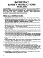
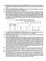
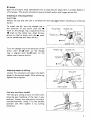
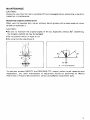
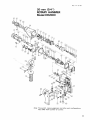
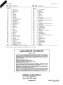
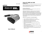
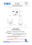
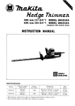
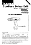
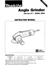
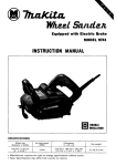
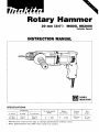
Rotary Hammer
I
20 mm (3/4") MODEL HRZOOO
Variable Speed
INSTRUCTION MANUAL
DOUBLE
INSULATION
SPECIFlCATl0NS
Capacities
In wood
In steel
18"
(11116")
13"
(112")
No load speed
(RPMI
In concrete
20 m m
(314")
0
~
1,200
Blows
per minute
0
~
4,200
Overall
length
330"
(13")
Net
weight
2.7 k g
( 6 Ibsl
SAFETY INSTRUCTIONS
(For All Tools)
WARNING: WHEN USING ELECTRIC TOOLS, BASIC SAFETY
PRECAUTIONS SHOULD ALWAYS BE FOLLOWED TO REDUCE
THE RISK OF FIRE, ELECTRIC SHOCK, AND PERSONAL
INJURY, INCLUDING THE FOLLOWING:
READ ALL INSTRUCTIONS.
1. KEEP WORK AREA CLEAN. Cluttered areas and benches invite injuries.
2. CONSIDER WORK AREA ENVIRONMENT. Don't use power tools in damp
or wet locations. Keep work area well lit. Don't expose power tools t o rain.
Don't use tool in presence of flammable liquids or gases.
3. KEEP CHILDREN AWAY. All visitors should be kept away from work area.
Don't let visitors contact tool or extension cord.
4. STORE IDLE TOOLS. When not in use, tools should be stored in dry, and high
or locked-up place - out of reach of children.
5. DON'T FORCE TOOL. It will do the job better and safer at the rate for which
it was intended.
6. USE RIGHT TOOL. Don't force small tool or attachment t o do the job of a
heavy-duty tool. Don't use tool for purpose not intended; for example, don't
use circular saw for cutting tree limbs or logs.
7 . DRESS PROPERLY. Don't wear loose clothing or jewelry. They can be caught
in moving parts. Rubber gloves and non-skid footwear are recommended
when working outdoors. Wear protective hair covering t o contain long hair.
8. USE SAFETY GLASSES. Also use face or dust mask i f cutting operation is
dusty.
9. DON'T ABUSE CORD. Never carry tool by cord or yank it t o disconnect from
receptacle. Keep cord from heat, oil, and sharp edges.
10. SECURE WORK. Use clamps or a vise t o hold work. It's safer than using
your hand and it frees both hands t o operate tool.
11. DON'T OVERREACH. Keep proper footing and balance at all times.
12. MAINTAIN TOOLS WITH CARE. Keep tools sharp and clean for better and
safer performance. Follow instructions for lubricating and changing accessories. Inspect tool cords periodically and if damaged, have repaired by authorized service facility. Inspect extension cords periodically and replace if
damaged. Keep handles dry, clean, and free from oil and grease.
13. DISCONNECT TOOLS. When not in use, before servicing, and when changing accessories, such as blades, bits, cutters.
2
14. REMOVE ADJUSTING KEYS AND WRENCHES. Form habit of checking t o
see that keys and adjusting wrenches are removed from tool before turning
it on.
15. AVOID UNINTENTIONAL STARTING. Don't carry tool w i t h finger on switch.
Be sure switch is OFF when plugging in.
16. EXTENSION CORDS. Make sure your extension cord is in good condition.
When using an extension cord, be sure t o use one heavy enough t o carry
the current your product will draw. A n undersized cord will cause a drop
in line voltage resulting in loss of power and overheating. Table 1 shows the
correct size t o use depending on cord length and nameplate ampere rating.
If in doubt, use the next heavier gage. The smaller the gage number, the
heavier the cord.
TABLE 1 MINIMUM GAGE FOR CORD SETS
I
1
Total Length of Cord in Feet
0 - 25
I
26
-
50
I
51
-
100
I
101
-
150
~
Ampere Rating
More
Not More
Than
Than
0
-
6
10
12
-
6
10
12
16
AWG
18
18
16
14
16
16
16
12
;:
14
1
14
12
12
Not Recommended
17. OUTDOOR USE EXTENSION CORDS. When tool is used outdoors, use only
extension cords intended for use outdoors and so marked.
18. STAY ALERT. Watch what you are doing, use common sense. Don't operate
tool when you are tired.
19. CHECK DAMAGED PARTS. Before further use of the tool, a guard or other
part that is damaged should be carefully checked t o determine that it will
operate properly and perform its intended function. Check for alignment of
moving parts, binding of moving parts, breakage of parts, mounting, and any
other conditions that may affect its operation. A guard or other part that
is damaged should be properly repaired or replaced by an authorized service center unless otherwise indicated elsewhere in this instruction manual.
Have defective switches replaced by authorized service center. Don't use
tool if switch does not turn it on and off.
20. GUARD AGAINST ELECTRIC SHOCK. Prevent body contact w i t h grounded
surfaces. For example; pipes, radiators, ranges, refrigerator enclosures.
21. REPLACEMENT PARTS. When servicing, use only identical replacement parts.
22. POLARIZED PLUGS. TO reduce the risk of electric shock, this equipment has
a polarized plug (one blade is wider than the other). This plug will fit in a
polarized outlet only one way. If the plug does not fit fully in the outlet,
reverse the plug. If it still does not fit, contact a qualified electrician t o install
the proper outlet. Do not change the plug in any way.
3
VOLTAGE WARNING: Before connecting the tool t o a power source (receptacle,
outlet, etc.) be sure the voltage supplied is the same as that specified on the
nameplate of the tool. A power source w i t h voltage greater than that specified
for the tool can result in SERIOUS INJURY t o the user - as well as damage t o
the tool. If in doubt, DO NOT PLUG IN THE TOOL. Using a power source w i t h
voltage less than the nameplate rating is harmful t o the motor.
ADDITIONAL SAFETY RULES
1. Wear a hard hat (safety helmet), safety glasses and/or face shield. It is also
highly recommended that you wear a dust mask, ear protectors and thickly
padded gloves.
2. Be sure the bit is secured in place before operation.
3. Under normal operation, the tool is designed t o produce vibration. The screws
can come loose easily, causing a breakdown or accident. Check tightness
of screws carefully before operation.
4. In cold weather or when the tool has n o t been used for a long time, let the
tool warm up for several minutes by operating it under no load. This will
loosen up the lubrication. Without proper warm-up, hammering operation
is difficult.
5. Always be sure you have a firm footing.
Be sure no one is below when using the tool in high locations.
6. Hold the tool firmly w i t h both hands.
7. Keep hands away from moving parts.
8. Do not leave the tool running. Operate the tool only when hand-held.
9. Do not point the tool at any one in the area when operating. The bit could
fly out and injure someone seriously.
I O . When drilling or chipping into walls, floors or wherever "live" electrical wires
may be encountered, DO NOT TOUCH ANY METAL PARTS OF THE TOOL!
Hold the tool by the insulated grasping surfaces t o prevent electric shock
if you drill or chip into a "live" wire.
11. Do not touch the bit or parts close t o the bit immediately after operation;
they may be extremely hot and could burn your skin.
SAVE THESE INSTRUCTIONS.
4
Bit grease
Coat the bit shank head beforehand with a small amount (about 0.5- 1 g; 0.02-0.04'0z.)
of bit grease. This chuck lubrication assures smooth action and longer service life.
Installing or removing drill bit
CAUTION :
Always be sure that the tool is switched off and unplugged before installing or removing
the bit.
To install the bit, turn the change ring in
the direction of the arrow until the a
mark on the change ring is aligned with the
Imark on the rubber cap. Align the key
groove on the bit shank with the
mark
on the rubber cap and insert the bit.
Turn the change ring in the direction of the
arrow until the a mark on the change
ring is aligned with the 8 mark on the
rubber cap to secure the bit.
Adjusting depth of drilling
Loosen the wing bolt and adjust the depth
gauge to the desired depth. After adjusting,
tighten the wing bolt.
Key groove
Rubber cap
Rubber cap
Change ring
Wing bolt
I
Side grip (auxiliary handle)
The side grip swings around to either side,
allowing easy handling of the tool in any
position. Loosen the side grip by turning it
counterclockwise, swing it to the desired
position and then tighten it by turning
clockwise.
5
Switch action
Tool speed is increased by increasing pressure on the trigger. To start the tool, simply
pull the trigger. Release the trigger to stop.
For continuous operation, pull the trigger
and then push in the lock button. To stop
the tool from the locked position, pull the
trigger fully, then release it. A speed control screw is provided so that maximum
tool speed can be limited (variable). Turn
the speed control screw clockwise for
higher speed, and counterclockwise for
lower speed.
Higher _Lower
Speed control screw
Lock button
CAUTION:
Before plugging in the tool, always check to see that the trigger switch actuates properly
and returns to the "OFF" position when released.
Reversing switch action
This tool has a reversing switch to change
the direction of rotation. Move the reversing switch lever to the &>position for
clockwise rotation or the 4%)
position for
counterclockwise.
CAUTION :
*Always check the direction of rotation
before dril Iing.
*Use the reversing switch only when the
tool comes to a complete stop. Changing
the direction of rotation before the tool
stops may ruin the tool.
Torque limiter
The torque limiter will actuate when a certain torque level is reached. The motor will
disengage from the output shaft. When this happens, the bit will stop turning.
CAUTION :
*As soon as the torque limiter actuates, switch o f f the tool immediately. This will help
prevent premature wear of the tool.
0 Hole saws, core bits, diamond core bits, etc. cannot be used with this tool. They tend
to pinch or catch easily in the hole. This will cause the torque limiter to actuate too
frequently .
6
Hammer drilling operation
*Position the bit at the location for the
hole, then pull the trigger.
Do not force the tool. Light pressure
gives best results. Keep the tool in position and prevent it from slipping away
from the hole.
* D o not apply more pressure when the
hole becomes clogged with chips or particles. Instead, run the tool a t an idle,
then remove from the hole. By repeating
this several times, the hole will be cleaned
out.
.
-I---
/
Dust cup
Use the dust cup to prevent dust from falling over the tool and on yourself when
performing overhead drilling operations.
Attach the dust cup to the bit as shown in
the figure. The dust cup can be attached to
the bit up to 14.5 mm (9/16') in diameter.
-Bit
CUP
Drilling in wood or metal
Use the optional drill chuck assembly (consisting of drill chuck, chuck adapter and
screw) for drilling up to 13 mm (1/2") in
metal and up to 18 mm (11/16") in wood.
To install it, refer to "installing or removing drill bit".
Drill chuck
CAUTION :
Be sure to use only the drill chuck assembly or chuck adapter assembly specified in this
manuaI (See "accessories" ).
The use of any other drill chuck assembly or chuck adapter assembly may cause damage
to the drill chuck or chuck adapter. Also, the screw holding the drill chuck and chuck
adapter together will come loose when reversing the tool.
NOTE :
If you need assemble the drill chuck and chuck adapter assembly, proceed as follows.
7
rCh
key /
Secure the drill chuck in a vise or similar
securing devise. Place the chuck key in
one of the three holes so that the chuck
body will not turn.
Remove the screw from the chuck adapter assembly and screw the chuck adapter into
the drill chuck. Use a wrench to tighten the chuck adapter securely, applying about 300400 kgf . cm (21.6-28.9 Ib . f t ) torque. [Note : you can obtain 300-400 kgf . cm (21.628.9 Ib . ft) torque by applying pressure of 30-40 kg (66-88 Ibs) to the wrench while
holding the portion 10 cm (4") from the wrench head.]
Open the chuck jaws fully and insert the
screw through the chuck opening. Tighten
the screw counterclockwise with a screwdriver.
-
Screw
8
MAINTENANCE
CAUTION:
Always be sure that the tool is switched off and unplugged before attempting to perform
inspection or maintenance.
Sharpening tungsten-carbide tip bit
When your bit becomes dull, use an ordinary bench grinder with a wheel made of silicon
carbide to resharpen it.
CAUTION :
Be sure to maintain the original angles of the tip. Especially without 60" chamfering,
the tungsten-carbide tip may be damaged.
0 Do not quench the bit in water or oil.
Do not grind the sides B and C.
0.5
ir
A - A' Cross section
To maintain product SAFETY and RELIABILITY, repairs, carbon brush inspection and
replacement, any other maintenance or adjustment should be performed by Makita
Authorized or Factory Service Centers, always using Makita replacement parts.
9
ACCESSOR I ES
CAUTION :
These accessories or attachments are recommended for use with your Makita tool specified in this
manual. The use of any other accessories or attachments might present a risk of injury to persons.
The accessories or attachments should be used only in the proper and intended manner.
0 Tungsten-carbide
tip bits
0
Chuck key S13
Part No. 76341 1-7
0
Drill chuck S13
Part No. 763047-2
1
o Chuck adapter
Part No. 122331-8
t-
0
Hammer grease 30 g; 1 or.
Part No. 181490-7
0
Depth gauge
Part No. 321 144-6
0
Bit grease 100 g; 3.5 or.
Part No. 181573-3
0
Dust cup
Part No. 421342-3
0
Hex wrench5
Part No. 783203-8
0
Grip 37
Part No. 273496-0
0
Safety goggles
0 Steel
carrying case
Part No. 181872-3
10
Part No. 191686-2
Nov.-14-'91
EN
Note: The switch, noise suppressor and other part configurations
may differ from country t o country.
11
Jan - 0 8 - ' 9 2
K O D E L HR2000
O
',:'M
1
2
3
4
5
6
7
8
11
12
13
14
15
16
17
18
20
21
22
23
24
25
26
27
28
29
30
31
32
33
34
35
36
37
38
39
40
41
1
1
1
1
1
1
1
1
1
1
1
1
1
1
1
1
1
1
1
1
1
1
1
1
1
1
1
1
1
1
1
1
1
1
1
1
1
2
-
Ring Spring 26
Flat Washer 13 5
Rubber Ring 17
Idler
Impact Bolt
0 Ring 1 0
0 Ring 10
Tool Holder
0 Ring 10
Spur Gear 39
Compression Spring 35
Flat Washer 34
Ring Spring 30 5
0
1
1 Seal 28
Ball Bearing 6904LLU
Gear Housing
Change Ring
Cap 37
Washer 28
Crank Housing
Pin 7
Striker
42
43
44
45
46
47
48
49
50
51
54
55
56
0 Ring 16
67
Peton Cylinder
Piston Joint
Washer
Bell Crank
Washer
Gear Housing Packing
Gear Housing cover
Pl" 8
0 Ring 26
Ball Bearing 6200
011 see1 12
Fan 62
ARMATURE ASSEMBLY
[With Item 38 64 & 851
Baffle Plate
Hex Bolt M5x55 [With Washer & Bond1
68
69
US
$tD
DESCRIPTION
1
2
1
1
1
1
1
1
1
2
1
2
2
1
1
4
2
5
1
1
1
1
1
1
1
1
1
58
59
60
61
62
63
64
65
66
70
71
72
3
73
74
75
16
77
78
79
81
82
83
84
-
1
1
1
1
1
1
1
1
2
1
1
-
FIELD ASSEMBLY
Rivet 0-5
Name Plate
Motor Housing
Switch
0 Ring 11
Cord Guard
Cord
Strain Relief
Pan Head Screw M4x18 IWith Washerl
Handle Cover
Pan Head Screw M 4 x t 4 lWith Washerl
Brush Holder
Switch
Switch Cover
Pan Head Screw M5x55 lWith Washer]
Carbon Brush
Pan Head Screw M4x22 IWith Washer)
Flat Washer 14
Bsll Bearing 608L8
Insulation Washer
Rubber Pin 4
Cap Square Neck Bolt Max35
Crank Joint
Crank Shaft
Reraining Ring R-32
Ball Bearing 6002
Pan Head Screw M5x14 (With Washerl
Bell
Grip Base
Rubber Washer 4 5
Wing Bolt M5x15
Grip 32
Needle Cage 808
Needle Cage 808
Change Ring Cover
Roller 7
Steel Ball 7 1
Ring 20
Note: The switch and other part specifications may dlffer from country to country
MAKITA LIMITEDONE YEAR WARRANTY
Warranty Policy
Every Makaa tool i s thorou ly inspectedand tested before Leaving the factow. I t IS warranted to
be free of defects from workaishnp and materials for the period of ONE YEAR from the date of
original purchue. Should any trouble develop dunng this one-year period. return the COMPLETE
tool, freight prepaid, to one of Makita'S Factory or Authorized Selvice Centers. If inspeetion shows
the trouble is caused by defective workmanship or material, Makita will repar (01 at our optlon.
replace) without charge.
This Warranty doer not apply where:
repairs have been made or attempted by others:
repairs u c required because of normal wem and tear
The tDol has been abused. m w s e d or improperly maintained;
alterations have been made to the tool.
I N NO EVENT SHALL MAKITA BE LIABLE FOR ANY INDIRECT, INCIDENTAL OR CONSEQUENTIAL DAMAGES FROM THE SALE OR USE OF THE PRODUCT THIS DISCLAIMER
APPLIES BOTH DURING AND AFTER THE TERM OF THIS WARRANTY.
MAKITA DISCLAIMS LIABILITY FOR ANY IMPLIED WARRANTIES, INCLUDING IMPLIED
WARRANTIES OF "MERCHANTABILITY~ AND "FITNESS FOR A SPECIFIC PURPOSE,"
AFTER THE ONE-YEAR TERM OF THIS WARRANTY.
Thin Warranty gives you specitie legal rights. and you may also have other rights whxh vary from
state to state. Some states do not allow the e ~ c l ~ s morn limitation of incidental or Consequential
dnmager PO the above limitation or exclusion may not apply to you. Some states do not allow
Iimitnti& on how long an implied warranty lasts, so the above limitation may not apply to YOU.
Makita Corporation
3-11-8, Sumiyoshi-cho,
Anjo, Aichi 446 Japan
8834860063
PRINTED I N JAPAN
1995 -4 - N