1
PSZ 19:16 (Pind. 1/07)
UNIVERSITI TEKNOLOGI MALAYSIA
DECLARATION OF THESIS / UNDERGRADUATE PROJECT PAPER AND COPYRIGHT
Author’s full name :
NUR FARAHIN BINTI ASA @ ESA
Date of birth
:
09 DECEMBER 1989
Title
:
COUNTER SYSTEM USING MICROCONTROLLER FOR VISITOR
Academic Session :
2011/2012
I declare that this thesis is classified as :
CONFIDENTIAL
(Contains confidential information under the Official
Secret Act 1972)*
RESTRICTED
(Contains restricted information as specified by the
organisation where research was done)*
OPEN ACCESS
I agree that my thesis to be published as online open
access (full text)
I acknowledged that Universiti Teknologi Malaysia reserves the right as follows:
1. The thesis is the property of Universiti Teknologi Malaysia.
2. The Library of Universiti Teknologi Malaysia has the right to make copies for the
purpose of research only.
3. The Library has the right to make copies of the thesis for academic exchange.
Certified by :
SIGNATURE
891209-01-6436
(NEW IC NO. /PASSPORT NO.)
Date : 1st JULY 2012
NOTES :
*
SIGNATURE OF SUPERVISOR
ASSOC. PROF. DR. NIK RUMZI NIK IDRIS
NAME OF SUPERVISOR
Date : 1st JULY 2012
If the thesis is CONFIDENTIAL or RESTRICTED, please attach with the letter from
the organization with period and reasons for confidentiality or restriction.
“I hereby declare that I have read this thesis and in my opinion this thesis is
sufficient in terms of scope and quality for the award of the degree of Bachelor of
Engineering (Electrical-Power)”
Signature
:
……………………………………
Name of Supervisor :
ASSOC. PROF. DR. NIK RUMZI NIK IDRIS
Date
1st JULY 2012
:
COUNTER SYSTEM USING MICROCONTROLLER FOR
VISITOR
NUR FARAHIN BINTI ASA @ ESA
A thesis submitted in partial fulfilment of
the requirements for the award of the
degree of Bachelor of Engineering (Electrical-Power)
Faculty of Electrical Engineering
Universiti Teknologi Malaysia
JULY 2012
“I declare that this thesis entitled “Counter System Using Microcontroller for
Visitor” is the result of my own research except as cited in the references. The thesis
has not been accepted for any degree and is not concurrently submitted in
candidature of any other degree.”
Signature
: …………………………………
Name
: NUR FARAHIN BINTI ASA @ ESA
Date
: 1 JULY 2012
ii
This thesis is dedicated to my loving parents, always be my inspiration. You are the
reason I step forward to this stage.
To teammate, my beloved friends, I will never forget your support.
And to those who helped me a lot, thank you very much. You are always in my
minds.
Special thanks to Prof. Dr. Nik Rumzi Nik Idris. Your valuable help and
suggestions makes my special word for you..
“Thank You..”
iii
ACKNOWLEDGEMENTS
Alhamdulillah. In the name of Allah, the Most Compassionate, the Most
Merciful. Praise be to Him, the Lord of the universe. Blessing and solution of peace
to Holy Prophet Muhammad (peace be upon him) and his companion and those who
follow him as upholding the cause of the right religion.
First of all I wish to express my appreciation and gratitude to my supervisor,
Dr. Nik Rumzi bin Nik Idris for his valuable guidance and support throughout the
whole two semesters until this project done successfully. There will be many
obstacles to complete this project without his support, advice, insight and guidance
given.
Besides, I would like to thank and sincere appreciation to my beloved mother,
father and siblings for their support, counsel, understandings and encouragement till I
stand here. Their mentally moral support and understanding during this year
including money matter was an inspiration to my future.
Not forgotten to all my friends who gave me helps technically and mentally
throughout these academic years in completing my project especially to Sharul
Ridzuan, Nor Khairunnisa and Zakwan Sabli. They were very helpful in completing
my software and hardware development. We have been doing this project together
with patience although face many problems on hardware. Thank you so much for
what you gave.
v
ABSTRACT
Nowadays, people often waste energy without realizing it. Home automation
concept had been introduced to save power consumption. A counter system circuit
was designed and set up to turn on or off the lights. This system is useful when
someone in a room forgot to turn off the light when they leave only when nobody left
in the room. Moreover, this device can be used to measure the number and direction
of people traversing a certain passage or entrance. So, the counter system can count
visitor pass through in a room. It turns on the light when the first visitor enters the
room while it will turn off the lighting system when the last person leaves the room.
In addition, it also can measure the height of the visitor. However, this device only
limited with a room which provide an entrance only. The system uses
microcontroller with PIC 18F452 and displayed at LCD display. Microcontroller use
microC programming and this program consider limited probabilities but can be
replacing with improved programming. In addition, system comes with sensor as
input and relay as the output. The sensor and relay is responsible to detect visitor and
control the lighting system. This concept can be further utilized by the hotels or
building management to control their lights in their units effectively. Therefore the
power consumption can be managed and reduce the emission of green house gases
indirectly. Several assumptions and probabilities were made when setting up this
prototype system and future improvement and research of this work also been
studied.
vi
ABSTRAK
Pada masa kini, manusia sering membazirkan tenaga tanpa disedari. Sistem
automatik telah diperkenalkan untuk menjimatkan penggunaan kuasa. Litar sistem
mengira telah direka bentuk untuk menghidupkan dan mematikan lampu. Sistem ini
amat berguna apabila seseorang di dalam bilik lupa untuk mematikan lampu apabila
mereka keluar dan apabila tiada siapa yang ada di dalam bilik. Selain itu, peranti ini
boleh digunakan untuk mengukur bilangan dan hala tuju mereka yang melalui laluan
tertentu atau pintu masuk. Jadi, sistem pengira boleh mengira bilangan pelawat yang
masuk atau keluar dari bilik. Ia menghidupkan cahaya apabila pengunjung pertama
memasuki bilik manakala akan mematikan sistem pencahayaan apabila orang yang
terakhir meninggalkan bilik. Di samping itu, ia juga boleh mengukur ketinggian
pengunjung. Walau bagaimanapun, peranti ini hanya terhad kepada sebuah bilik
yang menyediakan satu pintu masuk dan satu pintu keluar sahaja. Sistem ini
menggunakan “microcontroller” dan PIC 18F452, hasil akan dipaparkan di paparan
LCD. “Microcontroller” menggunakan pengaturcaraan microC dan program ini
mempertimbangkan kebarangkalian yang terhad tetapi boleh diperbaiki dengan
pengaturcaraan yang lebih baik. Di samping itu, sistem ini dilengkapi dengan sensor
sebagai input dan geganti sebagai output. Sensor dan geganti bertanggungjawab
untuk mengesan pelawat dan mengawal sistem pencahayaan. Konsep ini boleh
digunakan di hotel atau pengurusan bangunan untuk mengawal sistem pencahayaan
dengan lebih berkesan. Oleh itu, penggunaan kuasa boleh diuruskan dan
mengurangkan pelepasan gas rumah hijau secara tidak langsung. Beberapa andaian
dan kebarangkalian dibuat semasa merekabentuk sistem prototaip dan pembaikan
dan penyelidikan projek ini juga dikaji sepenuhnya.
vii
TABLE OF CONTENTS
CHAPTER
1
2
TITLE
PAGE
DECLARATION
ii
DEDICATION
iii
ACKNOWLEDGEMENTS
iv
ABSTRACT
v
ABSTRAK
vi
TABLE OF CONTENTS
vii
LIST OF TABLES
x
LIST OF FIGURES
xi
LIST OF ABBREVIATIONS
xiv
LIST OF SYMBOLS
xvi
LIST OF APPENDICES
xvii
CHAPTER 1 : INTRODUCTION
1
1.1
PROJECT BACKGROUND
1
1.2
PROBLEM STATEMENT
2
1.3
OBJECTIVES
3
1.4
SCOPE
4
1.5
THESIS OUTLINE
5
CHAPTER 2 : LITERATURE REVIEW
6
2.1
INTRODUCTION
6
2.2
BACKGROUND
6
viii
2.3
3
2.2.1 COUNTER
6
2.2.2 MICRCONROLLER
8
2.2.3 SK40C
9
2.2.4 PIC 18F452
13
2.2.5 PIC PROGRAMMER
15
2.2.6 MICROC PRO
17
2.2.7 PICKIT 2
18
RELATED WORK
20
CHAPTER 3 : METHODOLOGY
22
3.1
INTRODUCTION
22
3.2
SOFTWARE IMPLEMENTATION
22
3.2.1 DEFINING THE TASK AND PROBLEM
23
3.2.2 DESIGNING THE SYSTEM
23
3.2.3 WRITING THE CONTROL PROGRAM
26
3.2.4 TESTING AND DEBUGGING
32
HARDWARE IMPLEMENTATION
33
3.3.1 PART I (USING SK40C)
33
3.3.2 PART II (COMPLETE PROJECT)
34
3.3.3 TYPE OF CALL FUNCTION
36
3.3.4 HARDWARE COMPONENT AND
38
3.3
DESIGN
4
RESULT AND DISCUSSION
44
4.1
INTRODUCTION
44
4.2
RESULT
45
4.3
DISCUSSION
50
ix
4.3.1 POSSIBILITIES THAT NEED TO BE
50
CONSIDERED
4.3.2 PROBLEM OF THE OVERALL SYSTEM
5
52
CONCLUSION AND RECOMMENDATION
55
5.1 INTRODUCTION
55
5.2 CONCLUSION
55
5.3 RECOMMENDATION FOR FUTURE
56
IMPROVEMENT
REFERENCES
57
APPENDIX A
61
APPENDIX B
66
x
LIST OF TABLES
TABLE NO.
2.1
TITLE
Label of Function
PAGE
12
xi
LIST OF FIGURES
FIGURE NO.
TITLE
PAGE
2.1
Counter
7
2.2
Microcontroller
9
2.3
Component connection to SK40C
10
2.4
Wire connection to SK40C
10
2.5
SK40C connection to breadboard
11
2.6
SK40 labeling
11
2.7
Circuit diagram of SK40C
12
2.8
PIC 18F452 pin diagram
14
2.9
PIC 18F452
14
2.10
UIC00B with USB and rainbow cable
16
2.11
a) microC PRO icon
18
b) microC PRO start page software
xii
2.12
PICkit 2 software
19
3.1
Block diagram of overall system
23
3.2
Overall flowchart design
25
3.3
Microc PRO Start Page
28
3.4
First page to create new project
28
3.5
Selecting the device
29
3.6
Choose suitable device clock
29
3.7
Select the path to save project
30
3.8
PICkit 2 Programmer detect PIC 18F452 device
31
3.9
The hex file is successfully imported to PIC
32
3.10
Relay circuit diagram
35
3.11
Sensor connection to SK40C
35
3.12
Analog-to-digital call function
36
3.13
Analog-to-digital call function for sensor 3
36
3.14
Call function to calculate height of visitor
37
3.15
Call function to display total visitor
37
xiii
3.16
Call function to display the welcome and greeting
38
3.17
PIC 18F452 type
39
3.18
SK40C board
39
3.19
Distance sensor block diagram
40
3.20
a) Output distance sensor characteristic
41
b) Distance sensor (IR proximity sensor)
3.21
Relay schematic diagram
42
3.22
Relay circuit used in project
43
3.23
a) LCD 16x2
43
b) LCD shows occupant in
4.1
Programming successfully compiled
45
4.2
a) System in off condition
46
b) RB6 LED turn on when count greater than 0
c) LCD display “Full Count” for count equal to five
4.3
a) RB7 LED turn on shows error when RB1 pressed
47
more than 0.5 second
b) RB7 LED turn on shows error when RB0 and RB1
pressed more than 0.5 second
4.4
RB6 turn off when counter equal zero
47
4.5
a) Fluorescent lamp turn on
48
b) Total occupant is greater than zero
xiv
4.6
a) Fluorescent lamp turn off
49
b) Total occupant equal zero
4.7
Counter show negative value
53
xv
LIST OF ABBREVIATIONS
ADC
-
Analog Digital Converter
A/D
-
Analog to Digital
FKE
-
Fakulti Kejuruteraan Elektrik
UART
-
Universal Asynchronous Receiver/Transmitter
EEPROM
-
Electronically Erasable Programmable Read Only Memory
AUSART
-
Addressable Universal Asynchronous Receiver Transmitter
SFR
-
Special Faction Register
GPR
-
General Purpose Register
CMOS
-
Complementary metal–oxide–semiconductor
ICD
-
Implantable Cardioverter-Defibrillator
PWM
-
Pulse-width modulation
USB
-
Universal Serial Bus
ICSP
-
In Circuit Serial Programming
xvi
PC
-
Personal Computer
MCU
-
Multipoint Control Unit
IR
-
Infrared
I/O
-
Input / Output
LED
-
Light Emitting Diode
PIC
-
Peripheral Interface Controller
RAM
-
Random Access Memory
COFF
-
Common Object File Format
IDE
-
Integrated Development Environment
ANSI
-
American National Standards Institute
ROM
-
Read Only Memory
LDR
-
Light Dependent Resistor
CPU
-
Central Processor Unit
PDIP
-
Programmed Dialogue with Interactive Programs
LCD
-
Liquid Crystal Display
IC
-
Integrated Circuit
xvii
NO
-
Normally Open
NC
-
Normally Close
xviii
LIST OF SYMBOLS
cm
-
Centimeter
Hz
-
Hertz
MHz
-
Mega Hertz
uF
-
Mikro Farad
V
-
Volt
KB
-
Kilo Byte
xix
LIST OF APPENDICES
APPENDIX
A
TITLE
PIC MICROCONTROLLER CODE OF COUNTER
PAGE
61
SYSTEM USING MICROCONTROLLER FOR
VISITOR (SK40C)
B
PIC MICROCONTROLLER CODE OF COUNTER
SYSTEM USING MICROCONTROLLER FOR
VISITOR (FULL SYSTEM))
66
CHAPTER 1
INTRODUCTION
1.1
PROJECT BACKGROUND
In a public place such as shopping malls and cinemas, data on the number of
visitor is frequently needed for marketing research or statistic purposes. Usually the
counting process is done manually by the officers who guard the entrance. If this
process is done for a long period of time, it will be prone to human errors. Same goes
to a room such as laboratory, main hall, mosque or bedroom. A counter can be
implemented to save energy by a specific system. For instance, lighting system is one
of the major problems nowadays which is wasted because of human negligence. To
overcome this problem, a system which is able to count automatically should be
developed. In this new modern technology, new design and new creation had been
made to save power consumption and energy. Various types of system and
development improved. Power electronics technology uses electronic circuits to
convert and control electric energy with optimum efficiency. Today, this technology
is part of most electrically powered machines and devices. Power electronics
technology also the key to increasing both the amount of electric power transmitted
over the grid and the efficiency of power use. Moreover, centre researchers have
made significant contributions in three areas critical to power electronics evolution:
powering of a new generation of microprocessors; developing technologies for
2
integration of power electronics components, such as circuits and sensors; and using
the integrated components for standardized methods of assembling power converters,
which are still custom-designed [23].
As human keep wasting energy, these problems will never solved only if a
new system designed to overcome this problem. In the aspect of energy conversion
thinking, a basic start such as lighting system which people consume the most can be
reduces by a few ideas. People always enter and leave a room such as bedroom, hall,
laboratory, classroom without notice the lighting system stay on for a long time with
nobody present in the room. A system can be designed so that when the room is
empty, the lighting system can be automatically off. So from this idea, this will save
electricity use for a building, saving cost and energy at the same time. This system
should include sensor and relay. A sensor or also called detector is a device that
measures a physical quantity and converts it into a signal which can be read by an
observer or by an instrument [5]. A relay is an electrically operated switch. Many
relays use an electromagnet to operate a switching mechanism mechanically, but
other operating principles are also used [6]. A sensor will detect visitor so that it will
trigger the relay to turn off and turn on the lighting system. This type of system had
been use widely in many building, many places and country. Even a street lamp uses
this method for energy conversion. This type of method will lead to power saving
energy and thus become the one way to overcome the problem of shortage of power
supply.
1.2
PROBLEM STATEMENT
A building in a company or university constantly use energy more than
needed. This is because the resident did not alert to save power consumption. A
3
lighting system in laboratory at Faculty Kejuruteraan Elektrik (FKE) , Universiti
Teknologi Malaysia always been detected did not turn off most of the night and
caused the increase in electricity bill and energy wasting. So, one of the method can
be use to solve this problem is to apply the counter system for visitor using
microcontroller.
A counter system can be design in many ways such as combination of gate
logic and microcontroller. Gate logic is simple and easy but this feature difficult to
varied and becomes complex if the system needs more improvement in requirements.
But, by the using of microcontroller, a system can be more complex but easy to
design. This system will be installed in a laboratory which focused on the main door.
This laboratory in FKE only use one way to in and out and so that, this system is
suitable for this purpose. A sensor will be use to detect a person enter and out from
the laboratory door and send signal to microcontroller. This microcontroller will
count up and down based on the programming that been embedded on the PIC. A
LCD display will inform the total occupant inside the laboratory and at the same time
will display the counting data when a person enter or leave the room.
1.3
OBJECTIVES
This project is carried out to reduce energy wasting by residents in faculty by
designing a prototype system with simple features. The objective of this project:
i.
To design a system that will automatically control the lighting system
ii. To differentiate whether a visitor enter or leave the room and consider the
probabilities using counter system
iii. To display the total visitor present in the laboratory and display the height of
the visitor
4
iv. To develop a programming for microcontroller to count up and down visitor
traversing a certain passage or entrance which in this case is the FKE
laboratory
v. This system can calculate height of the visitor
1.4
SCOPE
This project is mainly concerned to design a counter that will count visitor
and control the lighting system of a room or hall. Consequently, this system will
avoid people wasting energy when they forgot to turn off the light. However, there
are a few limitations on this project.
There are several scopes of the development of counter system for visitor
using microcontroller that is:
i) Visitor cannot stay in between the sensor for more than 50ms
ii) SK40C will be used to run the program IC PIC 18F452 is chosen as the
processor to store the program
iii) The developed system that count visitor which enter and leave the room,
display total occupant inside the room and calculate the height of a visitor
iv) Implement two IR proximity sensors (GP2YOA21YK).
v) Identifying the counter process (count up or countdown)
vi) Single entrance and single exit room
„
5
1.5
THESIS OUTLINE
This thesis consists of five chapters. In first chapter, it gives an overview with
commence on introduction and background of the project, problem statement, and
objectives.
Chapter Two discusses on the literature review of the system which includes
the overall device used in this project. For this part, it gives the idea on counter,
microcontroller and briefing about tool. In addition, the related work from previous
project which is similar also included.
Chapter Three presents the methodology of the project. This chapter is
divided into two main parts which are the design of software and the design of
hardware. The discussion on the methodology software implementation and
hardware assembly will be explained in detail.
Chapter Four covers on result and discussion. All the results obtained from
the project through testing and calibration process are explained and analyzed. This
part concern more on the problem occurred and solution to overcome the
weaknesses.
Last part, chapter Five is the conclusion and recommendation. This chapter
testifies the success of the project, limitation and the suggestion for the future
development related to this work.
CHAPTER 2
LITERATURE REVIEW
2.1
INTRODUCTION
This chapter brief in detail about the tools used and rough overview about this
project. From this chapter, the features of the all the device and software include in
this system are covered. There will be two parts; part 1 is about the background of
this project, while part 2 is about previous study that related to the proposed topic.
2.2
BACKGROUND
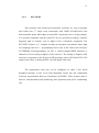
2.2.1
COUNTER
A counter that can change its state in either direction, under control of an up–
down selector input, is known as an up–down counter. The circuit can count numbers
7
in up and down modes depending upon the state of the selector. It can be used
to count the number of persons entering a hall in the up mode at entrance gate. In the
down mode, it can count the number of persons leaving the room by
decrementing the count at exit gate. It can also be used at gates of parking areas and
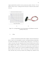
other public places. This circuit divided in three parts: sensor, microcontroller and
counter display. The sensor would observe an interruption and provide an input to
the controller which would run the counter in up/down mode depending upon the
selector setting. Based on the distance sensor that will be used in this system, the
distance is the main factor that will affect the output of the sensor. However, the
output will be the type of analog and in this stage; an analog to digital programming
converter will be needed to convert to the analog to digital output. In the range of 10
to 80 cm from the side of the door, sensor will sense the present of visitor, send
signal to microcontroller and save the updated data. All the data will be displayed on
16 x 2 characters LCD display with yellow backlight through the controller.
Once the visitor enters the room, sensor will detect the present of people and
counter will start to count up and vice versa. The counter will send signal to relay to
turn on the lighting system as the counter start to detect one visitor and above while
the relay will turn off only if the counter hit zero. For convenient, this counter can be
reset by administrator and any error on the counter can be repair.
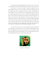
Figure 2.1 : Counter [14]
8
2.2.2
MICRCONTROLLER
A microcontroller is a highly integrated chip which performs controlling
functions.
A
microcontroller,
or
embedded
controller,
is
similar
to
a microprocessor as used in a personal computer. PIC microcontroller is a processor
with built in memory and RAM and can be use to control the input and output of the
project.
Microcontrollers are microprocessors integrated with peripherals on a single
integrated circuit. The microcontroller is essentially a microprocessor adapted for
control type applications. They are compact in size and yet retain the computational
power of traditional microprocessors, allowing them to be used in a multitude of
applications. The evolution of microprocessors into complex instruments and
machines has led to sophisticated, fast real-time control capability. Microprocessors
of 16 or 32 bit capability with associated interrupt handler chips, programmable
timer chips, ROM and RAM chips, have been replaced in many control function
instances by single chip I/O microcontrollers with all peripherals embedded on the
same chip with the microcontroller.
Microcontrollers differ from microprocessors in many ways. Microcontrollers
are independently programmable and can have a great deal of additional functionality
combined on the same integrated circuit. A typical microprocessor can access from a
megabyte to a gigabyte of memory, and is capable of processing 16, 32, or 64 bits of
information or more with a single instruction.
In this project, microcontroller is preferred because of it flexibility rather than
gate logic. If gate logic been use, this system is difficult to modified or improved. By
using microcontroller, the coding can be varied and replaced if new improvement
required.
9
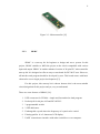
Figure 2.2 : Microcontroller [15]
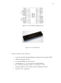
2.2.3
SK40C
SK40C is a start up kit for beginner to design and test a system. In this
project, SK40C suitable to fulfil this project as the circuit compatible with various
input and output. SK40C is another enhanced version of 40 pins PIC microcontroller
start up kit. It is designed to offer an easy to start board for PIC MCU user. However,
all interface and program should be developed by user. This board comes with basic
element for user to begin project development [13].
For this project, this start-up kit is chosen because this is the most suitable
circuit design that fit this project and yet, easy to understand.
These are some features of SK40C [10]:
1. ICSP connector for UIC00A - simple and fast method to load program.
2. Perfectly fit for 40 pins 16F and PIC18F PIC.
3. 2 programmable switch.
4. 2 LED indicators.
5. Exchangeable crystal where the frequency of crystal can be varied.
6. Existing pad for 16 x 2 characters LCD display.
7. UART connection to interface with other controller or even computer.
10
8. USB on board for certain PIC18F.
9. Users are able to utilize the function of PIC by directly plugging in the I/O
components in whatever way that is convenient to user. Bootloader can still
be applied in loading program.
10. Without PIC microcontroller to provide the freedom to choose PIC type.
The accessible of SK40C:
1. Components that needed connected onto the I/O port.
Figure 2.3 : Component connection to SK40C [16]
2. The I/O port can be extended to another board using jumper wire.
Figure 2.4 : Wire connection to SK40C [16]
11
3. I/O pins of the SK40C plugged onto a breadboard. Then, I/O pin can be
access through the breadboard.
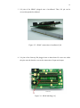
Figure 2.5 : SK40C connection to breadboard [16]
4. I/O pins of the Start-up Kit plugged onto a donut board. So user can solder
the pins onto the board to access the connection of input and output.
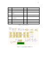
Figure 2.6 : SK40 labelling [16]
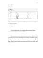
12
Label
Function
Label
Function
A
DC power adaptor socket
I
Programmable Push Button
B
USB Connector
J
Reset button
C
Toggle Switch for
power K
LCD contrast
supply
D
Power indicator LED
E
Connector
for
L
UIC00A M
JP8 for LCD Backlight
JP9 for USB
Programmer
F
LED Indicator
N
40 pin IC socket for PIC MCU
G
Header pin and turn pin
O
Turn pin for crystal
H
UART Connector
P
LCD Display
Table 1.1 : Lable of function
Figure 2.7 : Circuit diagram of SK40C [13]
13
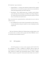
2.2.4
PIC 18F452
This powerful 100 nanosecond instruction execution are easy-to-program
with which have 77 single word instructions with CMOS FLASH-based 8-bit
microcontroller packs Microchip's powerful PIC architecture into a 40-pin package.
It is upwards compatible with the many PIC devices and thus providing a seamless
migration path of software code to higher levels of hardware integration. The
PIC18F452 features a 'C' compiler friendly development environment where high
level language such as C++ programming can be used. It also comes with 256 bytes
of EEPROM, Self-programming, an ICD, 2 capture/compare/PWM functions, 8
channels of 10-bit analog-to-digital (A/D) converter. The Analog-to Digital (A/D)
converter is important as this project use IR proximity sensor (GP2YOA21YK). The
output of the sensor is analog and PIC can read digital value only.
The synchronous serial port can be configured as either 3-wire Serial
Peripheral Interface or the 2-wire Inter-Integrated Circuit bus and Addressable
Universal Asynchronous Receiver Transmitter (AUSART). These features make it
ideal for instrumentation and monitoring, data acquisition and power conditioning
[25].
14
Figure 2.8 : PIC 18F452 pin diagram [18]
Figure 2.9 : PIC 18F452 [19]
The basic features of PIC 18F452 are:
1.
Consist of 40-pin Programmed Dialogue with Interactive Programs (PDIP)
2.
32KB flash program memory
3.
It can attain 40MHz max crystal speed:
4.
The RAM Bytes is 1,536 and contain 256 EEPROM Bytes
5.
PIC 18F452 provide timers which is 1 x 8 bit and 3 x 16-bit
6.
Analog-to-digital converter (ADC) consist of 8channel and 10-bit
7.
This PIC have 2 comparators
15
PIC divided into 3 types of memories:
i.
Program Memory - A memory that contains the program after the program
had been burned. As a reminder the program counter executes commands that
stored in the program memory one after the other [24].
ii. Data Memory - This is RAM memory type. It contains a special registers
such as SFR (Special Faction Register) and GPR (General Purpose Register).
The variables that stored in the data memory during the program are deleted
after we turn off the microcontroller [24].
These two memories have separated data buses, which makes the access to each one
of them very easy.
iii. Data EEPROM (Electrically Erasable Programmable Read-Only Memory) -
A memory that allows storing the variables as a result of burning the written
program [24].
Each one of them has a different role. Program memory and data memory is the
two memories that are needed to build a program while Data EEPROM is used to
save data after the microcontroller is turn off.
2.2.5
PIC Programmer
The PIC Programmer is a tool use to load a program to the PIC 18F452. The
PIC Programmer use USB to establish the connection between Laptop and
microcontroller in order to import the hex file into the PIC. The program will execute
when connected to computer and microcontroller turned on. PICkit 2 Readme
UIC00B is designed to program PIC Microcontroller that includes most of the PIC
16
family including PIC 18F452. Besides 8bit,16bit and 32bit PIC MCU also can be
programmed using this programmer. On board In Circuit Serial Programming (ICSP)
connector offers flexible methods to load such this program. USB port is commonly
available and widely used on Laptop and Desktop PC, thus they are very convenient
to use UIC00B.Program most of the +3.3V or +5V PIC. It is compatible with
PICkit2‟s UART Tool and Logic Tool and can program most of the current 8-bit, 16bit, and 32-bit Flash PIC microcontroller.
Moreover, it is flexible to use with Windows XP, Vista and 7 and also with
Microchip‟s PICkit 2. This PIC Programmer can be powered directly from USB port
and no external power required for UIC00B to function. This UIC00B supports onboard programming which eliminates the need of plug-in and plug-out of PIC MCU.
This flexibility also allows user to modify the program without removing the PIC
from the development board [15].
Figure 2.10 : UIC00B with USB and rainbow cable [20]
17
2.2.6
MicroC PRO
The mikroC PRO for PIC is a powerful, feature-rich development tool for
PIC microcontrollers. It is designed to provide the programmer with the easiest
possible solution to developing applications for embedded systems, without
compromising performance or control. PIC and C fit together well where nowadays
PIC is the most popular 8-bit chip in the world, used in a wide variety of
applications, and C, prized for its efficiency is the natural choice for developing
embedded systems. MikroC PRO for PIC provides a successful match featuring
highly advanced IDE, ANSI compliant compiler, broad set of hardware libraries and
comprehensive documentation. The mikroC PRO for PIC is a user-friendly and
intuitive environment.
This software mikroC PRO for PIC allows quickly develop and deploy
complex applications. The C source code can be writing using the built-in Code
Editor (Code and Parameter Assistants, Code Folding, Syntax Highlighting, Auto
Correct, Code Templates, and more.). It uses included mikroC PRO for PIC libraries
to dramatically speed up the development such as data acquisition, memory,
displays, conversions, communication and more. Besides, it monitors the program
structure, variables, and functions in the Code Explorer. microC PRO also generate
commented, human-readable assembly, and standard HEX compatible with all
programmers.
It use the integrated mikroICD (In-Circuit Debugger) Real-Time
debugging tool to monitor program execution on the hardware level where it is
convenient for beginner. Moreover, it able to inspect program flow and debug
executable
logic
with
the
integrated
Software
Simulator
and
generate
COFF(Common Object File Format) file for software and hardware debugging under
Microchip's MPLAB software [26].
18
a)
b)
Figure 2.11 : a) microC PRO icon b) microC PRO start page software
2.2.7
PICkit 2
The Microchip PICkit 2 device programmer and in-circuit debugger consists
of software which runs on a PC and hardware. Programmer-only software comes
with the PICkit 2. MPLAB includes both programming and in-circuit debugging
software. With the PICkit 2, user can step through assembly source code on-screen
while observing what the hardware is doing. User also can select registers to watch
by their labels as they can step through the program. The breakpoint also can be set.
So that, the program can be run at normal speed and exercise the hardware up to that
breakpoint. Next, the user can observe at the contents of the registers of their
choosing. The unit has a USB connector for serial communication with a host PC and
a 6-pin female header for communication with a flash PIC microcontroller
The PICkit 2 can operate in two operating modes which is programmer mode
and debugger mode. In the programmer mode, only the code is programmed into the
device for standalone where PICkit 2 is not connected during the operation. In both
the programmer and debugger operating modes, the user code is programmed into
the PIC microcontroller. While in the debugger mode, the PIC debugger code used
19
by the PICkit 2 is also programmed into program memory locations reserved for the
purpose.
The PICkit 2 can operate in two hardware configurations:
i.
Device programmer for programming flash devices.
ii.
Debugger/programmer for working with flash devices with in-circuit
debugging capability.
Figure 2.12 : PICkit 2 software
20
2.3
Related Work
i.
Street Light
Switch the lights on and off automatically during night and day time respectively.
This system used Light Dependent Resistor (LDR). The resistance changes according
to the amount of light falling on it. The system is said to reduce energy consumption
and CO2 emissions by up to 80 percent, plus it lowers maintenance costs and reduces
light pollution [11].
ii.
Motion Detector Lighting Control System
This system use motion detection to control lighting system. It consists of active
or passive sensor. However, this system has delay and depends on motion to
function. The weakness is if occupant is sleeping and static, the lighting system is
turn off.
iii. Bidirectional Visitor Counter
Two IR transmitter-receiver pairs are used at the passage. Microcontroller
controls counting and displays the number of persons present inside the hall. This
counter can change its state in either direction, under control of an up–down selector
input known as an up-down counter. It can count numbers from 0 to 9999 in up and
down modes depending upon the state of the selector. It also can be used to count the
number of persons entering a hall in the up mode at entrance gate. While in the down
mode, it can count the number of persons leaving the hall by decrementing the count
at exit gate [8].
21
iv. Occupancy Detection
Count the number of people that enter and exit each room (counter). If the
counter is more than zero, light will turn on. On the other hand, if the counter is
equal to zero, light turn off.
CHAPTER 3
METHODOLOGY
3.1
INTRODUCTION
The software implementation and hardware implementation are explained in
detail through this chapter. Software implementation discussed on the designing the
program by flowchart, writing and testing the program. The hardware methodology
is divided into two parts. First part discussed the method by using the microcontroller
independently. The second part is the implementation by combined sensor and relay
simultaneously. Basic knowledge on the design and high level language is acquired.
3.2
SOFTWARE IMPLEMENTATION
This project involves several steps:
1. Define the task
2. Designing the system
3. Writing the control program
4. Test and debug
23
3.2.1
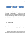
Defining the task and problem
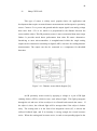
Figure 3.1 : Block diagram of overall system
The user accesses the abilities of the microcontroller by writing a program
that performs the desired functions. The main function of this project is to count
visitor but there are other aspect that must be consider. This system must
differentiate when a visitor enter or leave the room. Sensor only sense the present of
a person but it is microcontroller task to define either a person is enter or leaving the
laboratory. Besides that, a LCD display will be provide in this system to display the
total visitor exist in the room. Each time visitor come in and out, it can be monitor
through this LCD display and provide information about the present data.
3.2.2 Designing the system
Firstly, MicroC PRO and PICkit 2 v2.61 is a software need to be installed in
personal computer to ease the process of testing and improve the programming in the
next stage. This software is needed to design the programming and load the program
to the microcontroller. In this project, we must able to burn the program into PIC
using PIC programmer.
The first step in designing is choosing a suitable chip for this project. All
microcontrollers contain a CPU, and chances are that we can use any of several
24
devices for a specific project. Within each device family, we usually find a selection
of family members, each with different combinations of options. In this project, a IC
PIC 18F452A chosen because it is suitable for multitasking programs and serial
communication [1].
As a starting, SK40C is a start-up kit used to test this project with variable
input and output. In this system, the input will come from the sensor that detect
visitor while the output is a LCD display and connected to a relay which interface
with the lighting system.
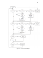
After considering all the possibilities and analyze the data, the flowchart of
the program is needed to understand and summarize the idea of this system. This
flowchart will be used to write the control program. Flowchart below shows the flow
on how generally microcontroller works and how it counting visitor using a specific
idea.
25
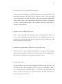
Figure 3.2 : Overall flowchart design
26
First of all, sensor 1 will detect any presence of object. If there are object
detected, the microcontroller will proceed to detect sensor 2, and in 0.5 second range,
there are object detected, the counter will counting up and relay will turned on. This
counting is represent a visitor is entering the laboratory. Henceforth, it is similar for
visitor that leaving the room. If sensor 2 detect the object first and a sensor 1 trace
0.5 second after sensor 1, the counter will counting down indicates a visitor is
leaving the laboratory. As there are nobody left inside the room, which counter will
hit zero, microcontroller will send data to control relay and turn off the lighting in the
room.
There also an additional function inside microcontroller to calculate the
height of the visitor that is entering and leaving the laboratory. It involve sensor 3 at
the top of the door to calculate the difference between the door and the detected
object that will equal to the height of the person.
3.2.3
Writing the control program
A programming language will be use depends on things such as desired
execution speed, program length and convenience. For this project, the most suitable
language is C++ language. The main advantages of C++ language are that there is
not much vocabulary to learn, and that the programmer can arrange the program very
fast. The high language C++ is very easy to learn and still a practical compact
language. It comprises a good semantic. The syntax of C is also clear [27]. This
language is a systems language suitable for low-level programming especially for
student. Finally, C language is easy to understand, has facilities for structured
programming and allows lexical variable scope and recursion, while a static type
system prevents many unintended operations [7].
27
The system model designed is the key element used in this study. Without
proper design and correct model, this study will not be successful. For this stage, a
necessary tool is needed to be used as a medium for carrying out the simulation.
After the control program is done without any error, hardware implementation is
proceeding.
There are several parts in programming which is:
i.
Programming using C language
For the embedded system in microcontroller, C language will be used to write
the instruction to the microcontroller. C language is suitable to program the
microcontroller because it is easy to organize and offers platform independently.
Besides, by using microC PRO, C language is highly recommended.
ii. Programming with microC PRO
MicroC PRO is easy and convenient to be used. Only with a few step, a
project can be designed. First, new project created to build a new program.
28
New project
Figure 3.3 : MicroC PRO start page
Click „Next‟ to skip the introduction.
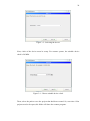
Figure 3.4 : First page to create new project
For the first step, choose device name. In this project, PIC 18F452 choose as
mentioned before.
29
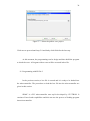
Figure 3.5 : Selecting the device
Next, clock of the device must be setup. For counter system, the suitable device
clock is 20 MHz.
Figure 3.6 : Choose suitable device clock
Then, select the path to save the project that had been created. So, next time if the
projects need to be open, this folder will show the counter program.
30
Figure 3.7 : Select the path to save project
Click next to proceed until step 5/6 and lastly click finish for the last step.
At this moment, the programming can be design and then build the program
to check the error. A Program with no error will be executed in hex file.
iii. Programming with PICkit 2
In the previous section, a hex file is created and it is ready to be loaded into
the microcontroller. The procedures to load the hex file into the microcontroller are
given in this section.
SK40C is a PIC microcontroller start up kit developed by CYCTRON. It
consists of boot loader capabilities and this can ease the process of loading program
into microcontroller.
31
After connecting the PIC programmer and the microcontroller, the PICkit 2
programmer is launched in PC.
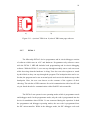
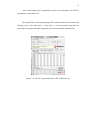
By using PICkit 2, the programming will be loaded to the microcontroller. By
clicking on the “auto import hex + write device”, select the project that had been
saved and the program should be imported to the microcontroller automatically.
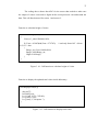
Figure 3.8 : PICkit 2 programmer detect PIC 18F452 device
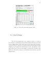
32
Figure 3.9 : The hex file is successfully imported to PIC
3.2.3 Testing and debugging
This is the most important part. After a program is written, or a section of
one, it needs to be tested and as necessary and any mistakes found need to be correct
to get it working properly. As the control program is done, the next phase, the project
is proceed to the next. The process of ferreting out and correcting mistakes is called
debugging. Easy debugging and troubleshooting can make a big difference in how
long it takes to get a system up and running [1]. In this project, this phase is the
hardest part where there are many error and obstacles faced towards the successful
designed system.
33
After the PIC 18F452 had been programmed, it placed to the SK40C and
connected to input and output to run the system. This chip had been programmed
several times before desired output is obtained. By using microcontroller, the
program can be easily change for convenience or depend on requirement of the
project. The input and output must be taken into consideration with a suitable range
of current to avoid damage on PIC 18F452. The complete coding can be referring to
Appendix B.
3.3
HARDWARE IMPLEMENTATION
Hardware implementation can be divided into two parts. The first part consist
SK40C and microcontroller only using the successful debug program. The other part
is the complete system including the IR proximity sensor and relay interfacing with
the lighting system.
3.3.1
Part I (Using SK40C)
The first part of this project involve SK40C and PIC 18F452 only. Once the
programming had been done, the program tested on SK40C board and the output
observed. In this stage, the push button pin is referred as the sensor. RB0 and RB1
indicate sensor 1 and sensor 2 respectively. RB6 and RB7 denote the output of the
microcontroller. During the testing, RB6 is the input of the relay that is connected to
the lighting system while RB7 is the connection to buzzer that will sound on if error
occurs. Both of this connection can be observed through RB6 and RB7 LED. As the
push button pin, RB1 and RB2 pressed according to the program, RB6 LED will turn
on. RB7 LED will turn on only if error had been detected. For instance, both push
34
buttons is pressed for a long period (more than 0.5 second), so it means the buzzer
will sound on and at the same time RB7 LED will remain lit.
For the first demo, the program is limit to 5 persons as maximum. When the
counter hit 5, the LCD will display “FULL COUNT” and the program will not count
if the number exceeds 5. This program is design for testing purpose and to observe
the reliability of the microcontroller. The full coding for this part can be referred to
Appendix A.
3.3.2 Part II (Complete Project)
In this part, sensor and relay is included during testing. Therefore, the C++
programming is altered a little bit so that it compatible to use with sensor and relay.
During this period, there are so many problem occurred and this will be discussed in
discussion part. One of them is when the sensor is not reliable and failed to obtain the
desired output compared to part I implementation. IR Proximity sensor had been
choosing for this system as the input while relay is function as the output of the
microcontroller. This part still used SK40C as the main board to test the program. So,
no additional circuit board is needed except for the relay and sensor connection. In
this case, a few addition on programming solved this problem which is analog-todigital converter programming is required. The complete programming can be
referred to Appendix B.
35
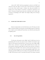
Figure 3.10 : Relay circuit diagram
Figure 3.11 : Sensor connection to SK40C [10]
36
3.3.3 Type of Call Function
Function of analog-to-digital converter to detect presence of object:
void readSensor(void)
{
int j;
for(j = 0 ; j < 10 ; j++)
// take analog result for 10 times
{
s1_value = s1_value + ADC_Read(1);
s2_value = s2_value + ADC_Read(2);
}
s1_value = s1_value/10;
//get average
s2_value = s2_value/10;
if (s1_value>95)
sensor1=0; //detect object
else
sensor1=1; //no object
if (s2_value>95)
sensor2=0; //detect object
else
sensor2=1; //no object
}
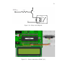
Figure 3.12 : Analog-to-digital call function
Function of analog-to-digital converter to calculate height:
void readSensor3(void)
{
int j;
for(j = 0 ; j < 10 ; j++)
// take analog result for 10 times
{
s3_value = s3_value + ADC_Read(3);
}
s3_value = s3_value/10;
//get average
}
Figure 3.13 : Analog-to-digital call function for sensor 3
37
The coding above shows that ADC for the sensor that needed to make sure
the output of sensor converted to digital before microprocessor can understand the
data. This call function used for sensor 1 and sensor 2.
Function to calculate height of visitor:
void calculateHight(void)
{
Vout=(s3_value*500000)/1024;
if ((Vout > 43945)&&(Vout < 279785))
to 2.8V = 8cm
{
Range_an=(Vout-19000)/2099;
Range=1000/Range_an;
Hight=210-Range;
}
}
// read only from 0.4V = 80cm
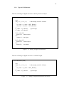
Figure 3.14 : Call function to calculate height of visitor
Function to display the updated total visitor inside laboratory:
void displayLCD(int y)
{
char txt[7];
IntToStr(y,txt);
Lcd_Cmd(_LCD_CLEAR);
Lcd_Out(1,7,txt);
Lcd_Out(1,1,"Occupant: ");
}
Figure 3.15 : Call function to display total visitor
38
Function to display the introduction for the beginning of the system:
void introduction(void)
{
unsigned char i;
Lcd_Cmd(_LCD_CLEAR);
Lcd_Out(1,1," WELCOME ");
Lcd_Out(2,1," SELAMAT DATANG ");
delay_ms(2000);
// Move text to the left 16 times
for(i=0; i<16; i++)
{
Lcd_Cmd(_LCD_SHIFT_LEFT);
delay_ms(250);
}
Lcd_Cmd(_LCD_CLEAR);
Lcd_cmd(_LCD_CURSOR_OFF);
}
Figure 3.16 : Call function to display the welcome and greeting
Connection between the sensor and microcontroller is referring to the base of
microcontroller that is defining on the programming. RA1 and RA2 is the base that
receives data from sensor 1 and sensor 2 respectively. Same goes to relay connection
that is done for part I which connected through RB7. The ground base of IR
proximity sensor and relay must be grounded in order to function.
3.3.4
Hardware Component And Design
i.
PIC 18F452
PIC 18F452 is used as processor in this project because of it flexibility and
advantages. This 40-pin PIC is put inside the SK40C and testing will be done using
SK40C itself. So, it is not necessary to take out the PIC every time the program
loaded to the microcontroller.
39
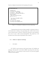
Figure 3.17 : PIC 18F452 type
ii.
SK40C
It is easy to use this hardware where the input and output can be any
device. No circuit designation required by using SK40C. Thus, this can ease the
project flow and reduce the error caused by failure during circuit designation.
Figure 3.18 : SK40C board
40
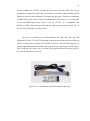
iii.
Sharp GP2YOA21
This type of sensor is widely used; popular choice for application and
development that require accurate distance measurements and inexpensive proximity
sensor. Connect +5v to power and ground and the output signal is an analog voltage
that varies from +3.5v to 0v, which is a proportional to the distance between the
sensor and the object. This IR proximity sensor is more economical than sonar range
finders. It provides much better performance than other IR sensor alternatives.
Interfacing to most microcontrollers is straightforward which the single analog
output can be connected to an analog-to-digital (ADC) converter for reading distance
measurements. The output can also be connected to a comparator for threshold
detection.
Figure 3.19 : Distance sensor block diagram [21]
An IR proximity sensor works by applying a voltage to a pair of IR light
emitting diodes (LED‟s) which in turn, emit infrared light. This light propagates
through the air and once it hits an object it is reflected back towards the sensor. If
the object is close, the reflected light will be stronger than if the object is further
away. The sensing unit is in the form of an integrated circuit (IC), it detects the
reflected infrared light, and if its intensity is strong enough, the circuit becomes
active. When the sensing unit becomes active, it sends a corresponding signal to the
41
output terminal which can then be used to activate any number of devices. For the
purpose of this exercise, a small green LED will turn on when the sensor becomes
active [9].
a)
b)
Figure 3.20 : a) Output distance sensor characteristic [10] b) Distance sensor (IR
proximity sensor) [22]
iv.
Relay
A relay is an electrically operated switch, simplest, easiest and useful device.
Most of relays use an electromagnet to operate a switching mechanism mechanically.
It contains electromagnet (coil), switch and spring. In this project, it is necessary to
control a circuit by a low-power signal that needs electrical isolation between control
and controlled circuits. Relay is a medium between the microcontroller circuit and
power lighting circuit. It also used when several circuits must be controlled by one
signal. Contactor is another type of relay that can handle the high power required to
directly control an electric motor. There are much type of relay which is protection
relay, solid state relay, reed relay, contactor relay, latching relay, automotive relay
42
and much more in the market. All these relay have same function but different in
specification [6].
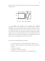
Figure 3.21 : Relay schematic diagram
As
known,
relay
consists
of
two
separate
and
completely
independent circuits. One is at the bottom and drives the electromagnet. A switch is
controlling power to the electromagnet in this circuit. When the switch is turn on, the
electromagnet will produce flux, and it attracts the armature while armature is acting
as a switch in the second circuit. When the electromagnet is energized, the armature
completes the second circuit and the light will turn on. On the other hand, the spring
pulls the armature away when the electromagnet is not energized and the circuit is
opened. In that case, the lighting system will be in off mode [12].
A relay must be considered through several variables:
1.
To activate the armature, user need to determined the voltage and current
2.
Maximum voltage and current that can flow through armature and armature
contacts
3.
The number of armatures
4.
The number of contacts for the armature
5.
Whether the contact is normally open (NO) or normally closed (NC)
43
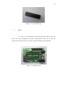
Figure 3.22 : Relay Circuit used in Project
v.
Liquid Crystal Display (LCD)
A 16x2 liquid crystal display is used to display the total occupant inside the
laboratory. This LCD also display either a visitor is enter or exit the room. It can be
observed when occupant is entering; an output shows “In” and along with the
increment of counter. Same goes if when occupant is leaving, LCD will display
“Out” in a line with the decrement of the counter. Height of occupant detect by
sensor 3 also displayed as output. The first line of LCD displays the total occupant
inside the laboratory while the second line displays the height of occupant as they
pass through the entrance.
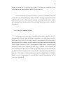
a)
b)
Figure 3.23 : a) LCD 16x2 b) LCD shows Occupant In
CHAPTER 4
RESULT AND DISCUSSION
4.1
INTRODUCTION
There are two parts discussed in this chapter which is divided to
microcontroller independently and completed circuit. The performance and the
ability of this project to function are mentioned on result. The microcontroller
functionality is explained and complete result after the whole circuit is combined is
observed. The system works as proposed and the desired output is obtained after a
few re-tested and re-calibrated is done. The level of achievement and the successful
in achieving the project objective as mentioned in the first chapter is determined.
45
4.2
RESULT
Figure 4.1 : Programming successfully compiled
The C++ programming is compiled successfully with no error. The full coding can
be referring to Appendix.
i.
Part I
For microcontroller part, the programming was tested using the SK40C
hardware before the project is combined together.
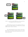
RB0 button define sensor 1 while RB1 indicate sensor 2. Imagine a person
pass through sensor 1 and 0.5 second after that, he should be pass through sensor 2,
RB1 must be pressed 0.5 second after RB0 to represent the actual system. For the
demo purpose, the programming is set to limit the counting up to five only. When the
counter count up to five, it will shows the counter reach “Full Count” and the counter
cannot count further.
46
RB6 initially
off condition
a)
RB6
turn on
Full
count
=5
b)
c)
Figure 4.2 : a) System in off condition b) RB6 LED turn on when count greater than
0 c) LCD display “Full Count” for count equal to five
RB6 LED indicates the relay that is connected to lighting system. Relay is on
if RB6 LED is turned on. RB7 LED indicates error. LED wills on if error occur. RB0
and RB1 define sensor 1 and sensor 2 respectively.
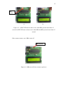
There is another situation where error occurs. Only sensor 1 either sensor 2
detect a presence of object, RB7 LED will turned on show that an error occurred.
Similar if both sensors detect an object and the object did not move on after 0.5
second, error also will occur.
47
RB7
turn on
a)
b)
Figure 4.3 : a) RB7 LED turn on shows error when RB1 pressed more than 0.5
second b) RB7 LED turn on shows error when RB0 and RB1 pressed more than 0.5
second
If the counter count to zero, RB6 is turn off.
RB6 turn off
Figure 4.4 : RB6 turn off when counter equal zero
48
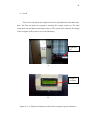
ii. Part II
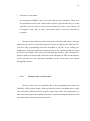
This is the result when the completed circuit is implemented on the laboratory
door. The first test when an occupant is entering, the counter counts up. The total
occupant is one and fluorescent lamp is turn on. The system also calculates the height
of the occupant as they enter or leave the laboratory.
Light turn
on
a)
Height of
occupant
b)
Figure 4.5 : a) Fluorescent lamp turn on b) Total occupant is greater than zero
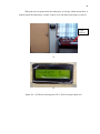
49
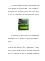
When the last occupant inside the laboratory is leaving, which means there is
nobody inside the laboratory, counter count to zero and fluorescent lamp is turn off.
Light
turn off
a)
b)
Figure 4.6 : a) Fluorescent lamp turn off b) Total occupant equal zero
50
4.2
DISCUSSION
4.2.1
Possibilities that need to be considered
During this project, there are many possibilities need to be considered. There are a
few conditions that take to consideration:
1. Someone swings their arms as they walk in.
Since the sensors are mounted at the around 140cm above the floor, it eliminates
most of the problems that would occur from this. In order to prevent the counter
from detect another object with similar shaped and their torso as another, the both
beams have to be broken for a minimum amount of time or the count will be
cancelled. The thickness of the average torso from the side is guaranteed that
both beams will be broken for this minimum amount of time given if a visitor
walks at a normal pace. The minimum time needed for both sensors to be covered
is 0.5 second. This configurable via network commands is saved in the PIC
18F452 flash memory.
2. Someone enters the doorway and stands there.
In this stage, counter will count it as error. Either sensor 1 or sensor 2 or both of
them detects an object for more than 0.5 second, error will occur. This condition
considered for a person that is stand close to either one of the sensor or both of
them and they not moving. A buzzer will beep as along the error is detected.
51
3. If someone walks in right behind the other person.
Unless both of the occupants are literally holding on to each other with no space
between them torsos, the beams will be restored as soon as the first person
passes. Before the next person can walk in order to prevent baggy clothing from
setting off the sensor, a very small time threshold must be met for both beams to
be clear. A microcontroller takes a few second to run the program before it
executes to the next stage.
4. When two person walking side-by-side.
This is a minor problem as the laboratory door is around 3ft wide. There is no
way a visitor will hardly enter such small area by walking side by side. One
should be in first while the other has to wait because with a limited size of the
door, they need to pass one by one.
5. Someone waves their hand over the sensor to run up the count.
They have to do it slow enough for both beams to be broken for the minimum
amount of time specified according to the programming. This could happen so in
this problem, occupant must be discipline enough not to do so.
6. Setting of the buzzer.
A buzzer had been setup to discipline the person who enters the laboratory. For
this simple counter, the programming is design with a few assumptions. When a
person stand at the door and either sensor 1 or sensor 2 detect the presence, the
buzzer will beep. Same goes if a person stand there and both sensor detect a
presence, the buzzer will sound.
52
7. Function of reset button.
A reset button on SK40C can be reset only if the system is unreliable. There are a
few possibilities such as the counter did not detect a person when they go in but
when they went out, there are one person left inside the room, so the counter will
be negative count. This is where reset button used to reset the total data of
occupant.
Distance sensor had been used in this project. Based on this sensor, analog to
digital must be used to convert the output from sensor to digital as the input for PIC.
And this ADC programming had been embedded to the PIC in the coding part.
Furthermore, this project had been improved with a few function which the sensor
will detect the height of the person pass through the entrance. This calculation of
height is made to suit the height of the door in the laboratory at FKE. As the distance
sensor had been use, the maximum expediency of the sensor give some benefit
through this counter.
4.2.2
Problem of the overall system
However, there are a few problems due to the programming that reduce the
flexibility of this system. Some of the time that the sensor is unreliable due to some
error, the microcontroller failed to read the output from sensor and consequences to
this counter will ignore the counting. Therefore, occupant entering the laboratory will
not equal to the occupant that leaves the room.
53
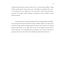
It will lead to error such that, the counter will be negative value or the counter
will never decrease to zero. Counter will be negative due to failure of detecting an
occupant entering the door. In this case, lighting is turned off even there is an
occupant left inside the laboratory. While the other side, counter will never decrease
to zero once the system failed to detect a visitor that leaving the room. Therefore,
even if the last person leaving the room, there is remainder one occupant considered
by counter that is not leaving due to the previous error even there are no more
occupants left inside the laboratory.
Figure 4.7 : Counter show negative value
The second problem is the counter will ignore if a visitor stand in between the
sensor or one of them. This means, once occupant stand in between the door, buzzer
will beep indicates error, and the occupant have no choice but to step back. If an
occupant failed to do so, it will lead to the unreliable of this system to operate
properly.
The sensor did not detect the height of occupant accurately. The data varies
even the same person pass through the system. It might be inability of IR proximity
sensor to detect the actual range of the occupant. This problem may be due to the
limit of the range of detection. By doing some analysis, it is concluding that the
sensor gives less efficient output to microcontroller when it detects the black and
gross surface. An assumption made that the light intensity at the surrounding of the
54
detection range affect the accuracy of the sensor. To overcome this problem, a bright
LED can be placed near to the sensor to give extra light at surrounding of the sensor.
In other hand, the error might due to the sensor fail to detect actual position of
occupant. For instance, sensor calculates the height of visitor‟s shoulder or their
hands from above.
At the earlier stage, when the program tested by using push button on SK40C,
the system function correctly but when all parts combine together, the output is not
as desired. Study had been conduct observed that the time interval to be broken
between both sensors is too small. This also due to the distance between the two
sensors and after a few calibrating and re-tested done, the system can function as
proposed. This sensor also needs to be calibrating to obtain the actual output.
CHAPTER 5
CONCLUSION AND RECOMMENDATION
5.1
INTRODUCTION
In this chapter, the entire objective achieved is explained in brief. A few
suggestions to improve the project is discussed in term of accuracy, stability and
extra function in for future development related to this project.
5.2
CONCLUSION
This project was successfully achieved its objective. Counter System using
Microcontroller for Visitor was successfully designed and implemented using
SK40C and PIC 18F452 as the main controller. The designed system controls the
lighting system automatically as desired. Microcontroller is able to differentiate the
visitor whether they are entering or exit the room. The system displays the total
visitor present in the laboratory and the height of the visitor through LCD.
A
56
programming to count up and down visitor traversing a certain passage or entrance is
operating successfully.
5.3
RECOMMENDATIONS FOR FUTURE IMPROVEMENT
For further study about counter system, the system can be improved by
solving the problem occurred by distance sensor. Calibration for sensor and bright
LED can be used to increase the accuracy of the distance sensor.
In addition, the study on programming to make the system more flexible is
required. This system can be upgrade where both sensors can differentiate the
direction of occupant after they stand between the sensors that caused an error.
Other than that, the negative value of the system can be eliminating on further works.
The systems will never count to negative value even there are error cause by sensor
or microcontroller. The failure of the system to detect person coming in or out from
the laboratory also can be improved by doing further research and adding new idea.
On further research, the idea to calculate height of visitor also can be upgrade so the
system is more reliable and accurate.
Moreover, any idea to design a system that can save power energy in a
building would be necessary to reduce power consumption and electricity bill. This
can avoid energy wasting when it not in use.
57
REFERENCES
1.
Jan Axelson Published, The Microcontroller Idea Book, Circuits, Programs, &
Applications featuring the 8052-BASIC Microcontroller (Lakeview Research),
1994.
2.
Akshay
Mathur,
Kuldeep
and
Singh
Nagla,
Microcontroller-based
Bidirectional Visitor Counter. article, 2007.
3.
Tai Wee Ming, Motion Detector Lighting Control System. Universiti Teknologi
Malaysia: Thesis B. Electrical Engineering (Telecommunication), 2011.
4.
Farina Binti Kamal , Sensor Application on Vehicle Following System.
Universiti Teknologi Malaysia: Thesis B. Electrical Engineering (Instrument
and Control), 2011.
5.
“Sensor”, Last access: June 2012.
http://en.wikipedia.org/wiki/Sensor
6.
“Relay”, Last access: June 2012.
http://en.wikipedia.org/wiki/Relay
7.
“C (programming language)” Last access: June 2012.
http://en.wikipedia.org/wiki/C_(programming_language)
58
8.
Engineer Garage, Automatic bidirectional visitor counter using 8051
microcontroller (AT89C51). June 2012.
http://www.engineersgarage.com/microcontroller/8051projects/Bidirectionalvisitor-counter-AT89C51-circuit
9
“IR Proximity Sensor”, Last access: June 2012.
http://www.g9toengineering.com/AllSaints/infraredproximity.htm
10 Cytron Technologies, Project 7, Analog sensor: range using analog distance
sensor. June 2012.
http://tutorial.cytron.com.my/wp-content/uploads/2011/08/P7-User-Manual.pdf
11 Ben Coxworth, Intelligent street light system uses 80 percent less electricity. 12
July 2011.
http://www.gizmag.com/motion-sensing-streetlight-system/19199/
12 Madeline Bullock, How relays work. June 2012.
http://electronics.howstuffworks.com/relay1.htm
13 “Cytron Technologies Head to Toe”, Last access: June 2012.
http://cytron.com.my/
14 Miniscience Inc, Digital counter (classic design). June 2012.
http://catalog.miniscience.com/Catalog/Counter/Digital_Classic_Counter.html
15 RobotShop, BasicATOM40-M Microcontroller Module. June 2012.
http://www.robotshop.com/basic-micro-basicatom40-m-microcontrollermodule-1.html
16 “SK40C user manual datasheet”, Last access: June 2012.
http://www.cytron.com.my/usr_attachment/SK40C_Users_Manual.pdf
59
17 “SK40C schematic diagram”, Last access: June 2012.
http://www.cytron.com.my/usr_attachment/SK40C.Rev2.0.0%20Schematic.pdf
18 “18FXX2 datasheet”, Last access: June 2012.
http://ww1.microchip.com/
19 AstanaDigital, PIC MICROCONTROLLER (PIC18F452. June 2012.
http://www.astanadigital.com/product.php?id_product=141
20 Eshore technologies, USB ICSP PIC PROGRAMMER V2010 (UIC00B). June
2012.
http://www.e-shore.com.my/homepage/eshop/developmenttools/programmer/usb-icsp-pic-programmer-uic00b
21 Electronic Experiment, Distance Sensor Sharp 2Y0A21 & LCD. June 2012.
http://electronicexperiments.blogspot.com/2011/08/distance-sensor-sharp2yoa21-lcd.html
22 Adafruit industries, IR distance sensor w/cable (10cm-80cm)GP2Y0A21YK0F. June 2012.
http://www.adafruit.com/products/164
23 “Spacedaily your portal to space”. June 2012
www.spacedaily.com
24 MicrocontrollerBoard.com, All YOU need to SUCCEED developing PIC
Microcontroller Projects with PIC Microcontroller Board. June 2012.
http://www.microcontrollerboard.com/
25 CSI, Circuit Specialist INC. June 2012.
http://www.circuitspecialists.com/
60
26 Scribd, Introduction to mikroBasic PRO for PIC. June 2012.
http://www.scribd.com/
27 R4R, C Programming. June 2012.
r4r.co.on
61
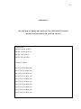
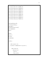
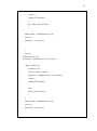
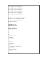
APPENDIX A
PIC MICROCONTROLLER CODE OF COUNTER SYSTEM USING
MICROCONTROLLER FOR VISITOR (SK40C)
//Define port
#define sensor1 portb.f0
#define sensor2 portb.f1
#define error portb.f7
#define relay portb.f6
//Define LCD port
sbit LCD_RS at RB4_bit;
sbit LCD_EN at RB5_bit;
sbit LCD_D0 at RD0_bit;
sbit LCD_D1 at RD1_bit;
sbit LCD_D2 at RD2_bit;
sbit LCD_D3 at RD3_bit;
sbit LCD_D4 at RD4_bit;
sbit LCD_D5 at RD5_bit;
sbit LCD_D6 at RD6_bit;
sbit LCD_D7 at RD7_bit;
62
sbit LCD_RS_Direction at TRISB4_bit;
sbit LCD_EN_Direction at TRISB5_bit;
sbit LCD_D0_Direction at TRISD0_bit;
sbit LCD_D1_Direction at TRISD1_bit;
sbit LCD_D2_Direction at TRISD2_bit;
sbit LCD_D3_Direction at TRISD3_bit;
sbit LCD_D4_Direction at TRISD4_bit;
sbit LCD_D5_Direction at TRISD5_bit;
sbit LCD_D6_Direction at TRISD6_bit;
sbit LCD_D7_Direction at TRISD7_bit;
void introduction(void);
void displayLCD(int y);
void main() {
int count=0,count1=0,txt[7];
trisb=0b00000011;
trisd=0;
portb=0;
adcon1=0;
lcd_init();
introduction();
while(1){
while (sensor1==0){
if((sensor1==0)&&(sensor2==0)){error=1;}
while (count<10){
if(sensor2==0)
{ count=13;
delay_ms(500);
63
if((sensor1==0)&&(sensor2==0)) continue;
count1++;
displayLCD(count1);
}
else{ delay_ms(50);count++;
}
}
while((count==10)&&(sensor1==0))
{error=1;}
if(sensor1==1){error=0;}
}
error=0;
while (sensor2==0){
if((sensor1==0)&&(sensor2==0)){error=1;}
while (count<10){
if(sensor1==0){
count=13;delay_ms(500);
if((sensor1==0)&&(sensor2==0)) continue;
count1--;
displayLCD(count1);
}
else{
delay_ms(50);count++;
}
}
while((count==10)&&(sensor2==0))
{error=1;}
if(sensor2==1){error=0;}
64
}
error=0;
if(count1>0){relay=1;}
if(count1==0){
relay=0;
}
count=0;
if(count1>=5){
Lcd_Cmd(_LCD_CLEAR);
Lcd_Cmd(_LCD_CURSOR_OFF);
Lcd_Out(1,1,"
Full
");
Lcd_Out(1,11,"Count:");
IntToStr(5,txt);
Lcd_Out(2,5,txt);
delay_ms(90);
count1=5;
}
else if(count1<0){count1=0;}
}
}
void introduction(void)
{
unsigned char i;
Lcd_Cmd(_LCD_CLEAR);
Lcd_Out(1,1,"
WELCOME
");
Lcd_Out(2,1," SELAMAT DATANG ");
delay_ms(2000);
65
for(i=0; i<16; i++) {
// Move text to the left 16 times
Lcd_Cmd(_LCD_SHIFT_LEFT);
delay_ms(80);
}
Lcd_Cmd(_LCD_CLEAR);
}
void displayLCD(int y)
{ char txt[7];
IntToStr(y,txt);
Lcd_Cmd(_LCD_CLEAR);
Lcd_Out(1,1,"Count:");
Lcd_Out(1,11,txt);
Lcd_Out(2,11,"per 30");
}
66
APPENDIX B
PIC MICROCONTROLLER CODE OF COUNTER SYSTEM USING
MICROCONTROLLER FOR VISITOR (FULL SYSTEM)
//Define port
#define error portb.f7
#define relay portb.f6
//Define LCD port
sbit LCD_RS at RB4_bit;
sbit LCD_EN at RB5_bit;
sbit LCD_D0 at RD0_bit;
sbit LCD_D1 at RD1_bit;
sbit LCD_D2 at RD2_bit;
sbit LCD_D3 at RD3_bit;
sbit LCD_D4 at RD4_bit;
sbit LCD_D5 at RD5_bit;
sbit LCD_D6 at RD6_bit;
sbit LCD_D7 at RD7_bit;
sbit LCD_RS_Direction at TRISB4_bit;
sbit LCD_EN_Direction at TRISB5_bit;
sbit LCD_D0_Direction at TRISD0_bit;
67
sbit LCD_D1_Direction at TRISD1_bit;
sbit LCD_D2_Direction at TRISD2_bit;
sbit LCD_D3_Direction at TRISD3_bit;
sbit LCD_D4_Direction at TRISD4_bit;
sbit LCD_D5_Direction at TRISD5_bit;
sbit LCD_D6_Direction at TRISD6_bit;
sbit LCD_D7_Direction at TRISD7_bit;
unsigned long s1_value=0,s2_value=0,s3_value=0;
unsigned long Vout, Range,Range_an,Hight;
int count=0,count1=0,txt[12],txt2[12];
int sensor1=1,sensor2=1;
void readSensor(void);
void readSensor3(void);
void calculateHight(void);
void introduction(void);
void displayLCD(int y);
void main()
{
TRISB=0b00000000;
TRISD=0;
TRISA=0xFF;
PORTB=0;
ADC_Init();
lcd_Init();
Lcd_cmd(_LCD_CURSOR_OFF);
introduction();
displayLCD(count1);
adcon1=6;
68
while(1)
{
readSensor3();
calculateHight();
//display hight
LongToStr(Hight,txt2);
Lcd_Out(2,15, "cm");
Lcd_Out(2,4,txt2);
Lcd_Out(2,1, "Ur Height:");
readSensor();
while (sensor1==0)
{
readSensor();
while (count<20)
{
readSensor();
if(sensor2==0)
{
count=23;
delay_ms(1000);
readSensor();
if((sensor1==0)&&(sensor2==0)){error=1; count1--;
if ((sensor1==1)&&(sensor2==1))continue; }
count1++;
displayLCD(count1);
//display "Out"
Lcd_Out(1,14,"In");
delay_ms(500);
Lcd_Out(1,14," ");
}
else
69
{
delay_ms(50);
count++;
}
}
readSensor();
while((count==20)&&(sensor1==0))
{
error=1;
readSensor();
}
readSensor();
if(sensor1==1)
{error=0;}
}
error=0;
readSensor();
while (sensor2==0)
{
readSensor();
while (count<20)
{
readSensor();
if(sensor1==0)
{
count=23;delay_ms(1000);
readSensor();
if((sensor1==0)&&(sensor2==0)){error=1;count1++;
if ((sensor1==1)&&(sensor2==1))continue; }
count1--;
displayLCD(count1);
70
//display "Out"
Lcd_Out(1,14,"Out");
delay_ms(500);
Lcd_Out(1,14," ");
}
else
{
delay_ms(50);
count++;
}
}
readSensor();
while((count==20)&&(sensor2==0))
{
error=1;
readSensor();
}
if(sensor2==1)
{error=0;}
}
error=0;
count=0;
// on/off lamp
if(count1>0)
relay=1;
else
relay=0;
if(count1>=200)
{
delay_ms(1000);
displayLCD(count1);
71
Lcd_Out(2,1,"
Full
");
}
if(count1<0) continue;
}//while(1)
}//main
void introduction(void)
{
unsigned char i;
Lcd_Cmd(_LCD_CLEAR);
Lcd_Out(1,1," WELCOME
");
Lcd_Out(2,1," SELAMAT DATANG ");
delay_ms(2000);
// Move text to the left 16 times
for(i=0; i<16; i++)
{
Lcd_Cmd(_LCD_SHIFT_LEFT);
delay_ms(250);
}
Lcd_Cmd(_LCD_CLEAR);
Lcd_cmd(_LCD_CURSOR_OFF);
}
void displayLCD(int y)
{
char txt[7];
IntToStr(y,txt);
Lcd_Cmd(_LCD_CLEAR);
Lcd_Out(1,7,txt);
Lcd_Out(1,1,"Occupant: ");
72
}
void readSensor(void)
{
int j;
for(j = 0 ; j < 10 ; j++)
// take analog result for 10 times
{
s1_value = s1_value + ADC_Read(1);
s2_value = s2_value + ADC_Read(2);
}
s1_value = s1_value/10;
//get average
s2_value = s2_value/10;
if (s1_value>95)
sensor1=0; //detect object
else
sensor1=1; //no object
if (s2_value>95)
sensor2=0;
//detect object
else
sensor2=1;
//no object
}
void readSensor3(void)
{
int j;
for(j = 0 ; j < 10 ; j++)
// take analog result for 10 times
{
s3_value = s3_value + ADC_Read(3);
}
s3_value = s3_value/10;
}
//get average
73
void calculateHight(void)
{
Vout=(s3_value*500000)/1024;
if ((Vout > 43945)&&(Vout < 279785))
2.8V = 8cm
{
Range_an=(Vout-19000)/2099;
Range=1000/Range_an;
Hight=210-Range;
}
}
// read only from 0.4V = 80cm to