1
HP MPX200 Multifunction Router Data
Migration User Guide
Abstract
This guide is intended for administrators of data migration services using the MPX200 Multifunction Router, with a basic
knowledge of managing SANs and SAN storage.
HP Part Number: 5697-2507
Published: March 2013
Edition: 3
© Copyright 2012–2013 Hewlett-Packard Development Company, L.P.
Confidential computer software. Valid license from HP required for possession, use or copying. Consistent with FAR 12.211 and 12.212, Commercial
Computer Software, Computer Software Documentation, and Technical Data for Commercial Items are licensed to the U.S. Government under
vendor's standard commercial license.
The information contained herein is subject to change without notice. The only warranties for HP products and services are set forth in the express
warranty statements accompanying such products and services. Nothing herein should be construed as constituting an additional warranty. HP shall
not be liable for technical or editorial errors or omissions contained herein.
Acknowledgments
Microsoft®, Windows®, Windows® XP, and Windows NT® are U.S. registered trademarks of Microsoft Corporation. Oracle® is a registered
trademark of Oracle and/or its affiliates.
Contents
1 Introduction...............................................................................................8
2 Getting started.........................................................................................10
Supported configurations.........................................................................................................10
Supported topologies.........................................................................................................10
Fabric configuration.......................................................................................................10
Data migration configuration..........................................................................................11
Supported FC fabrics..........................................................................................................16
Supported storage arrays....................................................................................................16
Hardware and software setup..................................................................................................17
Hardware setup.................................................................................................................17
Software setup...................................................................................................................18
3 Data migration objects..............................................................................19
Arrays...................................................................................................................................19
Data migration job groups.......................................................................................................20
Data migration jobs................................................................................................................20
Job attributes.....................................................................................................................20
Migration types.................................................................................................................21
Job scheduling..................................................................................................................21
Job states..........................................................................................................................22
Job failover and failback.....................................................................................................23
VPG......................................................................................................................................24
VPG examples...................................................................................................................24
Using VPGs on an FC array ...............................................................................................25
Presented targets....................................................................................................................25
Virtual presentation............................................................................................................25
Global presentation...........................................................................................................27
Migration to a thin-provisioned LUN .........................................................................................29
Recommended steps...........................................................................................................29
DML.....................................................................................................................................29
Remote peers.........................................................................................................................30
Online remote migration..........................................................................................................30
Method 1: Using Native IP..................................................................................................30
Native IP remote migration firewall ports..........................................................................31
Method 2: Using a fat pipe between local and remote data center...........................................32
Data scrubbing .....................................................................................................................33
Data scrubbing job attributes...............................................................................................33
Data scrubbing protections..................................................................................................33
Data scrubbing logs...........................................................................................................34
Data scrubbing licenses......................................................................................................34
Protection..............................................................................................................................34
Logs......................................................................................................................................34
Users....................................................................................................................................35
Host......................................................................................................................................35
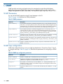
4 Data migration licenses.............................................................................36
Types of data migration licenses...............................................................................................36
Capacity-based licenses......................................................................................................36
Array-based licenses..........................................................................................................36
Types of data scrubbing licenses...............................................................................................36
Capacity-based licenses......................................................................................................36
Array-based licenses..........................................................................................................36
Contents
3
Installing a data migration license key.......................................................................................37
Applying an array-based license to a specific array.....................................................................37
Viewing data migration and scrubbing license usage..................................................................39
5 Performing data migration.........................................................................41
Typical data migration process.................................................................................................41
Configuring the fabric.............................................................................................................42
Presenting LUNs to the MPX200...............................................................................................43
LUN presentation from FC arrays..........................................................................................44
LUN presentation from iSCSI arrays......................................................................................45
Rescanning Targets.................................................................................................................45
Creating a data migration job group.........................................................................................46
Presenting LUNs to the server for online data migration................................................................46
Step 1: Inserting the MPX200 in the server data path for online data migration..........................46
Step 2: Create presented targets..........................................................................................47
Step 3: Zone in presented targets with initiator ports...............................................................48
Mapping LUNs to initiators......................................................................................................49
Mapping LUNs to hosts ..........................................................................................................50
Using remote peers.................................................................................................................51
Importing a remote array.........................................................................................................52
Setting array properties...........................................................................................................53
Creating a data migration job group.........................................................................................55
Using the data migration wizard...............................................................................................55
Starting the data migration wizard.......................................................................................55
Scheduling an individual data migration job.........................................................................56
Scheduling data migration jobs in batch mode......................................................................58
Starting serial scheduled jobs...................................................................................................60
Viewing the status of data migration jobs...................................................................................61
Viewing job details and controlling job actions...........................................................................62
Viewing system and data migration job logs..............................................................................63
System Log........................................................................................................................63
Data migration job log.......................................................................................................64
Using the Verifying Migration Jobs wizard.................................................................................66
Starting the Verifying Migration Job wizard ...............................................................................66
Scheduling verification of job options........................................................................................66
Acknowledging a data migration job........................................................................................67
Acknowledging offline migration jobs...................................................................................67
Acknowledging online, local migration jobs..........................................................................68
Acknowledging online, remote migration jobs........................................................................68
Removing an offline array........................................................................................................69
Creating and removing a DML.................................................................................................69
Using the Scrubbing LUN wizard..............................................................................................71
Generating a data migration report..........................................................................................73
6 Command line interface............................................................................76
User accounts........................................................................................................................76
User sessions.........................................................................................................................76
Admin session...................................................................................................................76
Miguser session.................................................................................................................76
Command syntax....................................................................................................................77
Command line completion..................................................................................................77
Authority requirements........................................................................................................77
Commands............................................................................................................................77
array................................................................................................................................77
array_licensed_port............................................................................................................79
compare_luns....................................................................................................................79
4
Contents
dml..................................................................................................................................82
get_target_diagnostics .......................................................................................................83
initiator............................................................................................................................86
iscsi.................................................................................................................................87
lunigmap..........................................................................................................................88
lunmask............................................................................................................................90
lunremap..........................................................................................................................91
migration..........................................................................................................................92
migration_group................................................................................................................98
migration_parameters.........................................................................................................99
migration_report..............................................................................................................100
readjust_priority...............................................................................................................100
remotepeer.....................................................................................................................101
rescan devices ................................................................................................................102
reset...............................................................................................................................102
save capture...................................................................................................................103
scrub_lun........................................................................................................................103
set.................................................................................................................................105
set array.........................................................................................................................106
set event_notification........................................................................................................109
set fc..............................................................................................................................109
set features......................................................................................................................110
set iscsi...........................................................................................................................110
set system.......................................................................................................................111
set vpgroups...................................................................................................................112
show array......................................................................................................................112
show compare_luns..........................................................................................................114
show dml........................................................................................................................115
show fc..........................................................................................................................116
show features..................................................................................................................116
show feature_keys............................................................................................................117
show initiators.................................................................................................................118
show initiators_lunmask....................................................................................................118
show iscsi.......................................................................................................................119
show logs.......................................................................................................................119
show luninfo....................................................................................................................120
show luns.......................................................................................................................122
show memory..................................................................................................................122
show mgmt.....................................................................................................................123
show migration................................................................................................................124
show migration group.......................................................................................................125
show migration_logs........................................................................................................126
show migration_luninfo.....................................................................................................127
show migration_params....................................................................................................128
show migration_perf.........................................................................................................128
show migration_usage......................................................................................................129
show perf.......................................................................................................................130
show perf byte................................................................................................................130
show presented_targets.....................................................................................................131
show properties...............................................................................................................132
show remotepeers............................................................................................................132
show scrub_lun................................................................................................................133
show system....................................................................................................................134
show targets....................................................................................................................134
show vpgroups................................................................................................................135
Contents
5
start_serial_jobs...............................................................................................................136
target rescan...................................................................................................................136
targetmap.......................................................................................................................137
7 Performance and best practices................................................................139
Performance factors..............................................................................................................139
Maximizing performance.......................................................................................................139
Optimal configuration and zoning..........................................................................................139
Expected time of completion (ETC) for data migration jobs.........................................................139
Overview........................................................................................................................139
Operational Behavior.......................................................................................................140
Offline ETC job...........................................................................................................140
Online ETC job...........................................................................................................141
Behavior characteristics................................................................................................141
Best practices.......................................................................................................................141
When to use offline data migration....................................................................................141
High availability and redundant configurations....................................................................141
Choosing the right DMS options........................................................................................142
General precautions.........................................................................................................142
8 Using the HP MSA2012fc storage array.....................................................144
MSA2012fc Array Behavior....................................................................................................144
Using Array-based Licenses for MSA2012fc Array.....................................................................144
Workaround for Using a Single Array License for MSA2012fc....................................................144
9 Restrictions............................................................................................146
Reconfiguring LUNs on a storage array...................................................................................146
Removing an array after completing data migration jobs...........................................................146
Serial scheduling jobs from multiple arrays...............................................................................147
10 Support and other resources...................................................................148
Contacting HP......................................................................................................................148
New and changed information in this edition...........................................................................148
Related information...............................................................................................................148
Websites........................................................................................................................148
Prerequisites.........................................................................................................................149
Typographic conventions.......................................................................................................149
HP Insight Remote Support software........................................................................................149
Product feedback..................................................................................................................150
11 Documentation feedback........................................................................151
A Configuring the data path through MPX200 for online data migration...........152
Windows multipath configuration...........................................................................................152
Linux multipath configuration..................................................................................................153
IBM AIX Multipath Configuration............................................................................................155
HP-UX multipath configuration................................................................................................156
Solaris multipath configuration...............................................................................................159
VMware multipath configuration.............................................................................................160
Citrix XenServer multipath configuration...................................................................................160
B Configuring the data path through MPX200 for iSCSI online data migration...162
Pre-insertion requirements......................................................................................................162
Insertion process with Microsoft MPIO.....................................................................................162
Insertion process with Dell EqualLogic DSM..............................................................................163
C SNMP..................................................................................................164
SNMP Parameters.................................................................................................................164
SNMP trap configuration.......................................................................................................164
6
Contents
Notifications........................................................................................................................165
qsrDMNotification object definition....................................................................................165
Data migration Solution notification object types..................................................................165
qsrJobId OBJECT-TYPE.................................................................................................165
qsrJobOwner OBJECT-TYPE..........................................................................................165
qsrJobCreator OBJECT-TYPE..........................................................................................165
qsrJobType OBJECT-TYPE..............................................................................................166
qsrJobOpCode OBJECT-TYPE........................................................................................166
qsrJobOperation OBJECT-TYPE......................................................................................166
qsrJobPriority OBJECT-TYPE...........................................................................................166
qsrJobStartType OBJECT-TYPE.......................................................................................166
qsrJobErrorCode OBJECT-TYPE......................................................................................166
qsrEventSeverity..........................................................................................................166
qsrBladeSlot...............................................................................................................166
qsrEventTimeStamp......................................................................................................166
D HP-UX Boot volume migration...................................................................168
Data migration.....................................................................................................................168
Stand alone systems (non vPar configurations)..........................................................................168
Example boot process in an Itanium server environment........................................................168
vPar configurations...............................................................................................................169
Example boot processes in vPar environments......................................................................170
PA-RISC systems..........................................................................................................170
Example of winona1 vpar boot................................................................................170
Itanium Systems..........................................................................................................170
Example of winona1 vpar boot................................................................................170
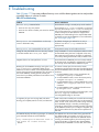
E Troubleshooting......................................................................................171
Glossary..................................................................................................174
Index.......................................................................................................178
Contents
7
1 Introduction
The MPX200-based DMS is block-based data migration that is independent of a SAN, server,
storage protocol (FC and iSCSI), and storage vendor. Because application unavailability during
data migration can critically impact services, DMS is designed to reduce down time. DMS supports
both online (local and remote) and offline data migration across FC and iSCSI storage arrays.
Anyone with knowledge of SAN or SAN storage administration will be able to use DMS.
Important data migration features include the following:
8
•
FC SAN vendor independent: The MPX200 supports B-Series, C-Series and H-Series fabrics.
MPX200 also supports data migration across multi-vendor FC fabrics.
•
Heterogeneous array support: The MPX200 supports data migration across heterogeneous
arrays (arrays manufactured by different vendors). For a list of the storage array types for
which DMS provides support, see “Supported storage arrays” (page 16).
•
Multi-protocol support: The MPX200 supports data migration across multiple storage networking
protocols, including FC and iSCSI. The MPX200 allows data migration between storage arrays
of the same or different protocols.
•
Migration to thin-provisioned storage: The MPX200 supports migration to “thin-provisioned”
storage. During the data migration process, the MPX200 can migrate from regular-provisioned
storage to thin-provisioned storage. When used with space reclamation tools, this type of
storage delivers significant cost savings in deploying new enterprise storage. For more
information, see “Migration to a thin-provisioned LUN ” (page 29).
•
Online remote migration: The MPX200 supports online data migration between two remote
data centers. A reasonable bandwidth (fat pipe) between two data centers is required to
handle the initial copy of the data and the change rate during the data copy. The data
migration rate depends on the round-trip latencies between two locations and the available
dedicated bandwidth.
•
Data scrubbing: The MPX200 supports data scrubbing. When retiring the old storage or
redeploying the storage, scrubbing data securely overwrites existing data and ensures that
old data cannot be retrieved.
•
Ease of use: The MPX200 has an intuitive GUI that provides many wizard-based operations
and a CLI. Both GUI and CLI provide user-level protection and ease of use.
•
Data security and sanity: The MPX200 provides features to classify storage arrays as source
only. This classification minimizes the chances of accidental data loss by ensuring that source
LUNs cannot be overwritten. The MPX200 also provides the Verify Migration Job wizard to
compare data on the source and destination LUNs, and to indicate whether the data copy
process occurred without corruption.
•
Migration job scheduling: The MPX200 provides several job scheduling options that minimize
downtime and maximize ease of use.
•
Load balancing: The Load Balancing option allows the aggregation of throughput from storage
array ports, which optimizes migration throughput performance for older-generation,
lower-speed arrays (such as 2 Gb and 4 Gb FC).
•
Data migration service logs: DMS logs are maintained separately from the system logs. DMS
logs are designed to help the service professional maintain a full, detailed history of each job
performed and can be submitted as a part of the migration report to the customer.
•
Data migration service reports: Provide reporting of data migration jobs that have either been
acknowledged or removed from the system. Each migration job entry in the report lists the job
details, including source and destination LUN information.
•
Logging and troubleshooting: System logs are designed to store a significant number of details
that can be used for debugging and troubleshooting. The save capture command, see
Introduction
“save capture” (page 103), helps to capture the configuration details, system logs, and MPX200
state at any time, and can be used for troubleshooting.
•
Licensing: DMS licenses provide capacity-based (per terabyte) and array-based licenses. For
more information, see “Data migration licenses” (page 36).
9
2 Getting started
This chapter provides information about supported configurations, and hardware and software
setup for using DMS with MPX200 and the HP mpx Manager.
Supported configurations
This section describes and illustrates the supported topologies (direct attach, fabric, and multipath),
and lists the supported fabric and array types.
Supported topologies
Supported topologies include fabric and multipath configurations.
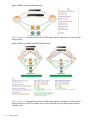
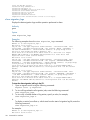
Fabric configuration
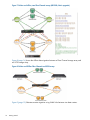
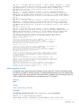
Figure 1 (page 10) and Figure 2 (page 10) show typical setups for data migration with a dual-fabric,
HA configuration with both array controller ports and one port from each MPX200 blade connected
to each fabric. This configuration enables the MPX200 to perform load balancing.
Figure 1 Single-blade high availability setup
Figure 2 Dual-blade high availability setup
10
Getting started
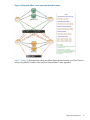
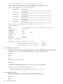
Figure 3 (page 11) shows the configuration used when you are:
•
Migrating from one vendor SAN to another vendor SAN.
•
Installing a new fabric and do not have enough ports available in the old fabric.
Figure 3 Migration between dissimilar vendor SANs
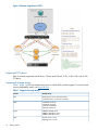
Data migration configuration
Figures in this section show the typical configurations used for offline and online data migration
using MPX200 models. “Performing data migration” (page 41) and “Configuring the data path
through MPX200 for online data migration” (page 152) also refer to these figures. The following
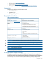
figure legend applies to all data migration figures in this section.
Figure legend
HBA <n>
Host Bus Adapter port number
SA <n>
Source array controller A port number
SB <n>
Source array controller B port number
DA <n>
Destination array controller A port number
DB <n>
Destination array controller B port number
BL<n> FC<n>:VPG<n>
MPX200 blade number, Fibre Channel port number, and virtual port group number
PT-SA <n>+VPG<n>
Presented target from MPX200 representing source array controller port number
and the VPGroup number used to present the LUNs to the MPX200 (online data
migration)
PT-SB <n>+VPG<n>
Presented target from MPX200 representing source array controller port number
and the VPGroup number used to present the LUNs to the MPX200 (online data
migration)
Solid lines
Physical connections between ports
Dashed and dotted lines
Presented target connections between ports
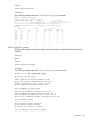
Figure 4 (page 12) illustrates the topology for offline data migration between two Fibre Channel
storage arrays.
Supported configurations
11
Figure 4 Offline, two Fibre Channel arrays
Figure 5 (page 12) illustrates both online and offline data migration between two Fibre Channel
storage arrays.
Figure 5 Online and offline, two Fibre Channel arrays
Figure 6 (page 13) illustrates both online and offline data migration between two Fibre Channel
storage arrays using MPX200 models with four Fibre Channel ports per blade (eight total Fibre
Channel ports).
12
Getting started
Figure 6 Online and offline, source array and destination array
Figure 7 (page 14) illustrates both online and offline data migration between two Fibre Channel
arrays using MPX200 models when the Fibre Channel fabric is also upgraded.
Supported configurations
13
Figure 7 Online and offline, two Fibre Channel arrays (MPX200; fabric upgrade)
Figure 8 (page 14) shows the offline data migration between a Fibre Channel storage array and
an iSCSI storage array.
Figure 8 Online and Offline Fibre Channel and iSCSI arrays
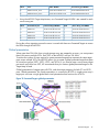
Figure 9 (page 15) illustrates remote migration using WAN links between two data centers.
14
Getting started
Figure 9 Remote migration using FCIP over WAN links
Figure 10 (page 16) illustrates remote migration using iSCSI.
Supported configurations
15
Figure 10 Remote migration for iSCSI
Supported FC fabrics
DMS is currently supported with B-Series, C-Series and H-Series, 2 Gb, 4 Gb, 8 Gb, and 16 Gb
FC fabrics.
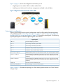
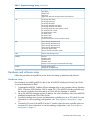
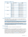
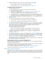
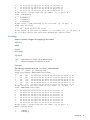
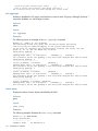
Supported storage arrays
Table 1 (page 16) lists the storage array types for which DMS provides support. To view the most
current compatibility matrix, see www.hp.com.
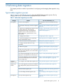
Table 1 Supported storage arrays
Vendor
Storage Array
Dell
EqualLogic PS Series iSCSI SAN Arrays
Compellent Series 30 and 40 Controllers
nl
EMC
CLARiiON CX family
CLARiiON AX family
Symmetrix DMX family
Symmetrix VMAX SE
nl
nl
nl
Fujitsu
ETERNUS DX400 arrays
ETERNUS DX440 S2 arrays
ETERNUS DX8400 arrays
nl
nl
HDS
Thunder 95xx V series
Lightning 99xx V series
nl
nl
16
Getting started
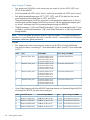
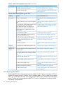
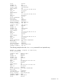
Table 1 Supported storage arrays (continued)
Vendor
Storage Array
AMS family
WMS family
USP family
TagmaStore Network StorageController model NSC55
nl
nl
nl
HP
HP
HP
HP
HP
HP
HP
HP
HP
HP
HP
HP
HP
nl
nl
nl
nl
nl
nl
nl
nl
nl
nl
nl
Storage MSA family
Storage EVA family
Storage XP P9000
Storage XP10000 and 12000
Storage XP20000 and 24000
Storage P4000 G2 SAN Solutions (iSCSI)
3PAR StoreServ 10000
3PAR StoreServ 7000
3PAR F-Class
3PAR T-Class
3PAR S-Class
SAN Virtualization Services Platform (SVSP)
nl
IBM
System Storage DS3000 family
System Storage DS4000 family
System Storage DS5000 family
System Storage DS8000 family
XIV Storage System family
Storwize V7000 Unified disk system
nl
nl
nl
nl
nl
NEC
D-Series SAN Storage arrays
NetApp
FAS270
FAS2000 Series
FAS3100 Series
FAS6000 Series
NetApp arrays that support Cluster-Mode technology
nl
nl
nl
nl
Xiotech
Emprise Storage family
Magnitude 3D 4000 family
nl
Hardware and software setup
Follow the procedures and guidelines in this section for setting up hardware and software.
Hardware setup
For information on installing MPX200, refer to the HP MPX200 Multifunction Router User Guide.
To set up the hardware for DMS:
1. To manage the MPX200, install the HP mpx Manager utility on any computer running Windows
2003, Windows 2008, RedHat, SuSE or Apple OS X. The MPX200 must be accessible over
the network connection from the machine on which HP mpx Manager is installed.
2. Set up the MPX200 management port IP address. For more information, refer to the MPX200
Intelligent Storage Router Quick Start Guide.
3. Connect the storage array (source and destination) controller ports to an FC switch. For more
information on various topology configurations, see “Data migration configuration” (page
11).
4. Connect the FC ports of the MPX200 to the FC switches where the array controller ports are
connected. For more information on various topology configurations, see “Data migration
configuration” (page 11).
Hardware and software setup
17
Software setup
Software setup for DMS includes the following:
•
Zoning: Perform zoning on the FC switches so that array controller ports are visible to the
MPX200, and the array is able to see virtual ports created by MPX200 FC ports and can
present LUNs to the MPX200.
•
LUN presentation: Ensure the appropriate data LUNs are presented from the storage arrays
to the MPX200.
•
Multipathing: For online data migration, ensure that the latest multipathing software is installed
on the host server and that both router blades are using the same firmware version.
High Availability considerations
For HA configurations where multiple FC ports (from one or both blades) of the router are visible
on the source or destination array, ensure that all WWPNs from the same virtual port group across
both blades of the MPX200 are configured under a single host or host group in the array
management software.
For the MPX200 to work correctly, you must set up all WWPNs from the same VPG (across both
blades) as a single host, and you must also project unique LUNs to this host in the storage array.
Set up multiple VPGs as different hosts in the storage array. Do not present the same LUN to multiple
VPGs (hosts associated with the MPX200). Failure to do so can lead to unpredictable and erroneous
behavior. For additional information, see “VPG” (page 24).
18
Getting started
3 Data migration objects
ThIs chapter covers the objects that the MPX200 DMS uses in data migration.
Arrays
DMS either discovers the FC target ports zoned in with the MPX200 FC ports, or it discovers and
logs into iSCSI qualified name (IQN) targets using iSCSI login. It forms an array when at least one
data LUN is presented to the MPX200 from that array. If no data LUN is presented to the MPX200,
all array ports are shown in the HP mpx Manager GUI and CLI as target ports.
DMS classifies the discovered storage array controllers into two categories: targets and arrays.
All array controller ports are initially identified as targets by the MPX200. After a single data LUN
is detected on the target, DMS forms an entity called an array. A specific LUN seen through multiple
FC target ports or IQN targets are grouped under a single array.
NOTE: The MPX200 may detect a single storage array as two storage arrays if another set of
LUNs are presented to the MPX200 through other target ports of the same array. This scenario
typically occurs when you have large storage arrays such as the EMC-DMX, HP-XP, or IBM DS8000.
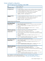
Configure the array entity for the DMS using the following attributes:
•
Symbolic name: Upon forming an array, the MPX200 Multifunction Router automatically
assigns it a symbolic name. HP recommends you change the array's symbolic name to a more
meaningful name as the migration log containing source and destination LUNs becomes
associated with that symbolic name.
•
Array type: DMS requires the classification of each array as either Source, Destination,
Source+Destination, or None. The Data Migration wizard, during the creation of migration
jobs, restricts assignment of a source LUN only from arrays that have an attribute Source or
Source+Destination. The wizard restricts assignment of a destination LUN only from arrays
with attribute Destination or Source+Destination. Use the array attribute Source+Destination
only when you need to create copies of a LUN on the same array.
Select the array type attribute None to exclude a storage array from data migration. The
MPX200 simultaneously supports both iSCSI connectivity and data migration service. Typically,
you would use the None attribute when the MPX200 provides only iSCSI connectivity for that
storage array or to define an array only for a data management LUN.
•
Array bandwidth: This feature is applied only to a source array. This value indicates the
maximum bandwidth the MPX200 can use for a data migration task from the source array .
The bandwidth is computed over all paths. The MPX200 is restricted to the user-assigned array
bandwidth to migrate the data. This feature allows other applications and servers using the
same source array to continue to perform at an acceptable performance level. The minimum
bandwidth required for data migration is 50 MBps.
•
Load balancing: The MPX200 detects all available active and passive paths to the LUN. Load
balancing balances the load for migration jobs over multiple active paths, thus improving the
migration rate. Disable load balancing only if there is a problem performing data migration.
NOTE: The MPX200 may detect a single storage array as two storage arrays if another set
of LUNs are presented to the MPX200 through other target ports of the same array. This
scenario typically occurs when you have large storage arrays such as the EMC-DMX, HP-XP,
or IBM DS8000.
•
Maximum Concurrent I/O: Because the source array is in use by hosts that may or may not
be part of the migration process, I/Os to the source array may exceed the maximum concurrent
I/Os supported by the array. Most arrays are equipped to handle this scenario and start
returning the SCSI status as 0x28(TASK SET FULL) or 0x08(BUSY) for the incoming I/Os that
exceed the arrays’ maximum concurrent I/O limit. The TASK SET FULL or BUSY SCSI status
Arrays
19
indicates congestion at the array controller. Thus, the MPX200 may require automated throttling
while trying to maximize migration performance by increasing concurrent I/Os. To control
automatic throttling and pacing of migration I/O, use the Enable I/O Pacing option.
•
Enable I/O Pacing: This feature is applied only to a source array. The MPX200 intelligently
manages concurrent migration I/Os to maximize overall migration throughput. If a Queue
Full or Busy condition is detected, the router throttles the migration I/O until it detects either
that the array queue is full or a busy condition. After the condition is cleared, it starts issuing
additional migration I/Os. This method maximizes host and migration I/O performance.
To achieve pacing, the router uses a configured, concurrent I/O limit and an internal counter
(current concurrent I/O limit, which is less than or equal to the configured limit) and a set of
steps for automatic throttling and pacing of migration I/O. The user sets the configured limit.
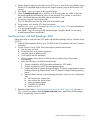
Data migration job groups
The MPX200 uses the concept of job groups to associate data migration jobs with user-defined
groups. A job group allows better management of data migration jobs. You can create a maximum
of 32 job groups that are shared between the two blades on a chassis. Both the HP mpx Manager
and the CLI provide options for removing and editing job groups.
Creating job groups is an opportunity to organize your data migration jobs. One typical
organizational model is creating groups that relate to application type or server class. For example,
you could classify a data migration job related to the Microsoft Exchange application as part of
the “Exchange” group and a data migration job related to a payroll application as part of the
“Payroll” group. Data migration jobs are then tracked separately within their respective groups.
Group information for each data migration job is recorded in the data migration log, see “Data
migration job log” (page 64).
If you do not define a group, all jobs are assigned to the default group, Group 0. You cannot
delete Group 0.
Data migration jobs
DMS processes data migration jobs according to a schedule. You can schedule a maximum of
512 jobs (256 jobs per blade) to run at any time. This section covers job attributes, migration
types, job scheduling, job states and job failover and failback.
Job attributes
Data migration jobs include the following attributes:
20
•
Migration type: Data migration jobs can be either online (local or remote) or offline. For more
information, see “Migration types” (page 21).
•
Source and destination LUN: For an offline migration job, you can configure a single source
LUN to migrate to one or multiple destination LUNs. For an online migration job, you can
configure a single source LUN to migrate to only one destination LUN. Any specified destination
LUN can be part of a single data migration job.
•
Job groups: For better manageability, you can configure data migration jobs to belong to a
specific, user-defined job group. By default, a job is assigned to a default group, Group 0.
For more information, see “Data migration job groups” (page 20).
•
Scheduling: You can configure data migration jobs to start immediately, start at a specified
time, or to use a priority-based serial scheduling. For more information, see “Job scheduling”
(page 21).
Data migration objects
•
I/O size: You can configure each data migration job to migrate data using a specified I/O
size. Different types of arrays and LUNs may provide optimum performance based on the I/O
size. The default size is 64 K.
•
Thin-provisioned LUN: MPX200 supports conversion of a regularly provisioned LUN to a
thin-provisioned LUN. If a destination LUN supports thin provisioning, you can opt to configure
this migration job as thin provisioned. For more information, see “Migration to a
thin-provisioned LUN ” (page 29).
The data migration wizard enables you to configure multiple jobs in a batch mode. The jobs
configured in batch mode have the same common attributes. For more information, see “Scheduling
data migration jobs in batch mode” (page 58).
Migration types
DMS supports both offline and online (local and remote) migration job types.
Offline data migration
DMS as an offline service allows you to migrate data between FC storage arrays, iSCSI storage
arrays, or FC and iSCSI storage arrays. Offline service assumes that when a data migration job
for the specified LUN starts, access to the LUN is blocked for servers and applications that are
using the source LUNs for data storage. You do not need to bring down these applications during
the initial setup and configuration. DMS lets you setup and configure tasks (except for immediate
scheduling of the jobs) while applications are running. Only during the actual data migration does
an application or a server need to be taken offline.
Online data migration
As an online service, DMS allows you to use the MPX200 to migrate data while an application
remains online and continues to access the source data. Online data migration can be either local
or remote (online data migration between two remote data centers). For online data migration,
you must configure the data path for the source LUNs through the MPX200. For more information,
see “Presenting LUNs to the server for online data migration” (page 46).
Job scheduling
The MPX200 data migration service provides multiple data migration job scheduling options to
optimize bandwidth usage and minimize application down time. It provides a priority-based serial
scheduling feature that enables you to queue migration jobs and execute them in serial or parallel
fashion, based on available resources.
You can schedule data migration jobs for execution in the following ways:
•
Immediate Schedule (start now)
•
Delayed Schedule (start at a later time within the next 30 days)
•
Serial Schedule (priority-based scheduling)
•
Configure Only (manually start later)
Immediate Schedule
Use the Immediate Schedule option to schedule a data migration job to instantly start data migration.
For offline data migration, ensure that both the source and destination LUNs are not being accessed
by any application when this option is selected.
Delayed schedule
Use the Delayed schedule option to schedule a data migration job to start at a later time. When
you select this option during configuration of a migration job, you are requested to enter the start
time. This allows you to configure a migration job during normal business hours and perform actual
Data migration jobs
21
data migration during off peak hours. For example, the online data migration initial copy operation
is performed during off peak hours.
Serial Schedule
The Serial Schedule option is designed to provide maximum flexibility for data migration. Even
though DMS supports 512 (256 per blade) simultaneous migration jobs, typical array performance
can be maximized by having only four to eight LUNs under active migration. Serial scheduling of
the job allows configuration of all 256 jobs per blade at the same time, while having fewer active
jobs at a time, which results in optimum array performance during data migration.
Serial scheduling allows you to configure migration jobs that can have the same or different priority.
If you need to configure a large number of jobs (256, for example), you can configure them in
batches such that the first four to eight jobs are scheduled at priority 1, the next four to eight jobs
at priority 2, and so on. This scheduling arrangement ensures that when the serial schedule starts,
no more than four to eight jobs are running simultaneously, and ensures optimum data migration
performance.
To achieve this performance, serial scheduling requires a job priority for each data migration job.
Multiple data migration jobs can have the same priority. Migration jobs with the same priority are
run together. Job priority 1 is highest and job priority 256 is lowest. After all the jobs are configured
for serial execution, you must schedule this batch of serially scheduled jobs. The batch can be
started immediately or at a later time. The Serial Data Migration Jobs Options dialog box provides
an easy way to start or schedule the batch.
After the serial batch starts to run, all jobs having the highest priority are completed before the
jobs scheduled at the next priority level start to execute. Only one serial schedule can be active at
any time.
For serial scheduled jobs, ensure that the migration LUNs for same-priority jobs are similar in size.
A substantial size difference could cause a smaller migration job to complete earlier than a larger
migration job. To maximize migration throughput, try to group jobs of approximately the same
size when you assign job priority.
Configure Only
The Configure Only option enables you to configure migrations jobs without a specified start time.
With this option, you must start the migration jobs at a later time. This option provides the advantage
that migration jobs can be started only with explicit user intervention.
One of the important uses of the Configure Only option is to verify all configured migration jobs
at your desk. When a migration job is configured, a detailed entry is created in the migration log.
After configuring all migration jobs, you can export the migration logs to a CSV file that you can
view use to validate the migration jobs using tools such as MIcrosoft Excel.
This option is also very useful for offline migration jobs when the exact down time of the application
is not known. Specify Configure Only when you need to configure all migration jobs without
requiring any application down time.
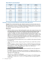
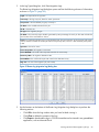
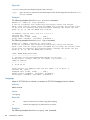
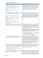
Job states
Table 2 (page 22) lists the possible data migration job states.
Table 2 Possible data migration job states
22
Job State
Description
Running
Job is currently running. You can pause or stop a running job.
Scheduled
Job is waiting to be run. You can stop and later restart a scheduled job.
Completed
Job is complete. You must acknowledge a completed job.
Data migration objects
Table 2 Possible data migration job states (continued)
Job State
Description
Paused
A running job has been paused by the user. You can resume or stop a paused job. A paused job that
is resumed continues running from the point where it was paused.
Stopped
A running, scheduled, failed, or pending job has been halted. You can restart or remove a job in the
stopped state. A stopped job that is restarted begins at the job start.
Failed
Sync up errors caused the online local migration job to fail, or a lost or full data management LUN
caused the online remote migration to fail.
Suspended
A job goes into a suspended state when access to either the source or destination LUN is lost.
Configured
A job has been created with the Configure Only option without a specified start time.
Synchronizing A job goes into this state when a data migration copy is completed and the router is synchronizing the
DRL blocks with the destination.
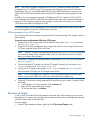
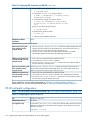
Job failover and failback
Data migration job failover and failback extends the current support for high availability. The
feature adds a new infrastructure for moving the migration job between blades. Utilizing this
infrastructure, migration jobs can be failed over and fail back between blades.
Migration job failover is a process of moving a migration job from its owner blade to a peer blade.
Migration job failback is a process of returning a previously failed over job to its original owner
when that job is restored after a failure. Both failover and failback virtually use the same process
and can be done manually by changing the migration ownership.
The feature also adds support for automatic failover. Automatic failover enables the second blade
to automatically take over the migration jobs of its peer when the peer goes down.
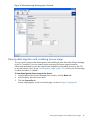
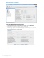
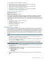
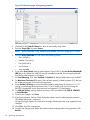
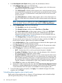
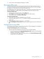
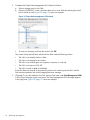
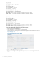
To configure automatic failover using mpx Manager:
1. In the left pane, select the Services tab, and then click Blade 1.
The Data Migration Info page appears in the right pane.
2.
Under Migration Parameters:
a. Enter a value in the Job Auto-failover Timer (Seconds) box that indicates the number of
seconds that the MPX200 waits for the source or destination LUN to come up after the
job owner blade is powered down or the source or destination LUN becomes unavailable
on the owner blade. The default value is 600.
b. Select the Job Auto-Failover Enable check box.
3.
4.
Click Set.
Repeat the preceding steps for Blade 2.
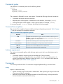
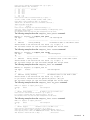
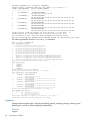
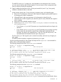
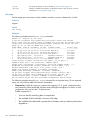
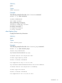
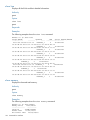
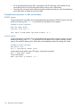
To set automatic failover parameters using the CLI, issue the migration_params set command.
For example:
MPX200 <1> (admin) (miguser) #> migration_params set
Local Migration Periodic Flush Interval (Secs, Min=30 ) [30 ]
Remote Migration Periodic Flush Interval (Secs, Min=300 ) [900 ]
Job Auto-failover Timer (Secs, Min=600 ) [900 ]
Job Auto-failover Policy (1=Disabled, 2=Enabled) [2 ]
Successfully Modified Migration Global Parameters
NOTE: You must change the Job Auto-failover Timer value before you make a destination or
source LUN unavailable. The timer value change applies only to the currently running job.
Data migration jobs
23
Job failover/failback rules:
•
Both MPX blades must have connectivity to both Source and Destination arrays.
•
Both MPX blades must have the same Group name available.
•
Failover happens when the owner blade remains in down state until the Autofailover timer
expires.
•
Failover happens if the resource (source/destination) LUN becomes unavailable on the owner
blade until the Autofailover timer expires.
•
Failback applies only when the job fails over due to the owner blade going down and returning
online.
•
Failback does not occur if the resources come back online on the owner blade.
To enable automatic failover and failback in HP mpx Manager, set the global migration parameters
Job Auto Failover Timer and Job Auto Failover policy.
NOTE: You must change the Job Auto-failover Timer value before you make unavailable
a destination or source LUN. The timer value change applies only to the currently running job.
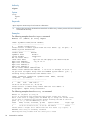
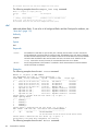
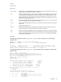
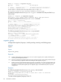
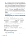
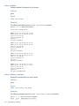
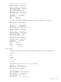
To perform manual failover and failback, issue the migration change_ownership command.
For example:
MPX200 <1> (admin) (miguser) #> migration change_ownership
Index Id Creator Owner Type Status Job Description
----- -- ------- ------ ---- ------------------------ -------------------------------------0 0 1 1 Online ..
Running DGC RAID-2:VPG1:000 to HP HSV210-1...
Please select a Index from the list above ('q' to quit): 0
Do you wish to continue with the operation(yes/no)? [No] yes
All attribute values for that have been changed will now be saved.
VPG
VPGs are designed to support concurrent migrations of both a large number of LUNs and multiple
servers. Each FC port of the MPX200 can present multiple virtual ports. The first four virtual ports
from each physical FC port (Blade1-FC1, Blade1-FC2, Blade2-FC1, and Blade2- FC2) on the
MPX200 form a single VPG. The following examples demonstrate how the VPGs are formed. By
default, VPG1 is enabled. Each VPG should be represented as a single host entity to the storage
array.
For more information about enabling and zoning VPGs, see the HP MPX200 Multifunction Router
User Guide, chapter covering configuration.
VPG examples
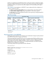
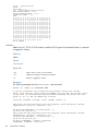
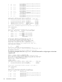
Table 3 (page 24) and Table 4 (page 25) present example VPG WWPNs. In Table 4 (page 25),
the bold numbers in the WWPN column indicate the various virtual ports.
Table 3 Example: Base WWPNs
24
Blade
FC Port
WWPN
1
1
21:00:00:c0:dd:13:2c:60
1
2
21:00:00:c0:dd:13:2c:61
2
1
21:00:00:c0:dd:13:2c:68
2
2
21:00:00:c0:dd:13:2c:69
Data migration objects
Table 4 Example: Four WWPNs per VPG
VPG
VPGroup1
VPGroup2
VPGroup3
VPGroup4
Virtual Port Number
WWPN
Blade1-FC1-VP1
21:00:00:c0:dd:13:2c:60
Blade1-FC2-VP1
21:00:00:c0:dd:13:2c:61
Blade2-FC1-VP1
21:00:00:c0:dd:13:2c:68
Blade2-FC2-VP1
21:00:00:c0:dd:13:2c:69
Blade1-FC1-VP2
21:01:00:c0:dd:13:2c:60
Blade1-FC2-VP2
21:01:00:c0:dd:13:2c:61
Blade2-FC1-VP2
21:01:00:c0:dd:13:2c:68
Blade2-FC2-VP2
21:01:00:c0:dd:13:2c:69
Blade1-FC1-VP3
21:02:00:c0:dd:13:2c:60
Blade1-FC2-VP3
21:02:00:c0:dd:13:2c:61
Blade2-FC1-VP3
21:02:00:c0:dd:13:2c:68
Blade2-FC2-VP3
21:02:00:c0:dd:13:2c:69
Blade1-FC1-VP4
21:03:00:c0:dd:13:2c:60
Blade1-FC2-VP4
21:03:00:c0:dd:13:2c:61
Blade2-FC1-VP4
21:03:00:c0:dd:13:2c:68
Blade2-FC2-VP4
21:03:00:c0:dd:13:2c:69
Using VPGs on an FC array
If an FC storage array is limited to 256 LUNs mapped to a host, enable multiple VPGs from the
MPX200. Each VPG becomes a separate host on the array. The VPGs enable the MPX200 to “see”
up to 1,024 LUNs from a single array (256 per VPG).
NOTE: In the scenario where at least one LUN under migration belongs to an HP-UX host, and
other LUNs belong to other host type operating systems (Windows, Linux, Solaris, or VMware),
use VPGs to create different host types for the HP-UX host and other hosts. Use one VPG to present
LUNs for the HP-UX host and different VPGs to present LUNs for the remaining OSs.
For more information on configuring VPGs on an FC array, see the chapter covering configuration
in the HP MPX200 Multifunction Router User Guide.
Presented targets
Presented targets includes both virtual presentation and global presentation.
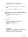
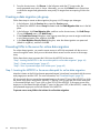
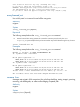
Virtual presentation
For online data migration, you must insert the MPX200 in the server’s data path. As a result, the
servers access the source LUNs through the MPX200. To insert the MPX200 in the server data path
and enable access to the source LUNs through the MPX200, you must first create a virtual
presentation of the source array target ports. This virtual presentation is referred to as a presented
target. A VPG and source array target port represents each presented target. Thus, a single source
array target port may have up to four presented targets, one associated with each VPG. (VPG1,
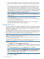
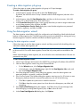
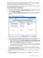
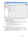
VPG2, VPG3, and VPG4). The example in Figure 11 (page 26) shows how to create multiple
presented targets by combining a target port on the source array with the MPX200 VPG.
Presented targets
25
Figure 11 Presented targets: virtual presentation
Figure 11 (page 26) shows:
•
LUNs from a single source storage array allocated to two servers. Use the Target Map Wizard
to configure two separate VPGs to map LUNs from the storage array to Server1 and Server2.
•
Four target ports (WWPNs) on the source array are zoned in with two VPGs (VPG1 and
VPG2) on the MPX200.
•
LUNs associated with VPG1 are for Server1, and LUNs associated with VPG2 are for Server2.
•
Four presented target ports (PT1, PT2, PT3, and PT4) depict the four source array target ports
discovered on VPG1. These presented targets (WWPNs) are zoned in with appropriate
adapter ports on Server1.
When LUNs (discovered through VPG2) are presented to Server2, four new presented targets
(PT5, PT6, PT7, and PT8) are created. The new presented targets depict the same four source
array target ports now discovered through VPG2, creating a total of eight presented targets
through the MPX200.
NOTE: HP recommends that if a single-source array FC target port is discovered through one
VPG across both blades, you should create only one presented target across all four physical FC
blade ports. For example, in Figure 5 (page 12), target ports SA1, SA2, SB1, and SB2 are
discovered on both blades through VPG1. Presented targets (PT) PT1 (SA1 + VPG1) and PT4 (SB2
+ VPG1) are presented through FC ports on Blade1, and PT2 (SA2 + VPG1) and PT3 (SB1 +
VPG1) are presented through Blade2.
Example:
•
26
Four target ports on the source array are zoned in with VPG1 from each MPX blade. Assuming
two fabrics, we connect FC1 from each blade to Fabric A and FC2 from each blade to FC2.
Fabric
Zone
VPG1 WWPN
Source Array port WWPN
A
Blade1-FC1-VP1_Zone
21:00:00:c0:dd:13:2c:60
50:05:08:b4:00:b4:78:cc
A
Blade2-FC1-VP1_Zone
21:00:00:c0:dd:13:2c:68
50:05:08:b4:00:b4:78:c8
Data migration objects
•
Fabric
Zone
VPG1 WWPN
Source Array port WWPN
B
Blade1-FC2-VP1_Zone
21:00:00:c0:dd:13:2c:61
50:05:08:b4:00:b4:78:cd
B
Blade2-FC2-VP1_Zone
21:00:00:c0:dd:13:2c:69
50:05:08:b4:00:b4:78:c9
Using the MPX200 Target Map feature, new Presented Target WWPN’s are created for each
source array port.
Fabric
Presented out port
Presented Target WWPN
VPG
Source Array port WWPN
A
Blade1-FC1
21:04:00:c0:dd:13:2c:60
1
50:05:08:b4:00:b4:78:cc
A
Blade2-FC1
21:04:00:c0:dd:13:2c:68
1
50:05:08:b4:00:b4:78:c8
B
Blade1-FC2
21:04:00:c0:dd:13:2c:61
1
50:05:08:b4:00:b4:78:cd
B
Blade2-FC2
21:04:00:c0:dd:13:2c:69
1
50:05:08:b4:00:b4:78:c9
During the online migration process the server is zoned with these new Presented Targets to access
the LUNs through the MPX200.
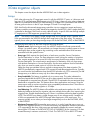
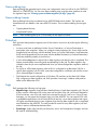
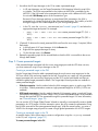
Global presentation
When more than 256 LUNs from a single storage array are mapped to a server, you must present
these LUNs across multiple VPGs. Each VPG on the MPX200 can see 256 LUNs.
To reduce the number of steps required to create presented targets that represent the same target
ports across multiple VPGs, the MPX200 allows you to create a global presented target that spans
all virtual port groups (VPG1, VPG2, VPG3, and VPG4). If you need to map a source array target
port across more than one VPG, HP recommends that you create a global presented target in the
Target Map Wizard.
Global presentation of targets spans all VPGs, and does target mapping for both FC and iSCSI
ports. Global presentation, like virtual presentation, is common for all VPGs. A single source array’s
target port can have a single global and virtual presentation that functions for all VPGs.
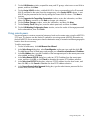
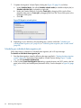
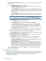
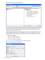
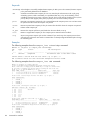
Figure 12 Presented Targets: global presentation
Presented targets
27
Figure 12 (page 27) shows:
•
Four target ports (WWPNs) on the source array are zoned in with two VPGs (VPG1 and
VPG2) on the MPX200.
•
LUNs associated with VPG1 are for Server1, and LUNs associated with VPG2 are for Server2.
•
Four global presented target ports (GPT1, GPT2, GPT3, and GPT4) depict the four source
array target ports discovered either on VPG1 and VPG2.
These presented targets (WWPNs) are zoned in with appropriate adapter ports on Server1,
and the same presented targets (WWPNs) are zoned in with the appropriate adapter ports
on Server2, creating a total of four presented targets through the MPX200.
•
Global Presentation 1 (SA1) and Global Presentation 2 (SA2) are presented through FC ports
on Blade1, and Global Presentation 3 (SB1) and Global Presentation 4 (SB2) are presented
through Blade2.
NOTE: Do not use global presentation and LUN masking together. To use global presentation,
issue the lunremap command to mask LUNs. To use the lunmask add command, use VPG-specific
presentation rather than global presentation.
Example:
•
•
28
Four target ports on the source array are zoned in with all VPGs from each MPX blade.
Assuming two fabrics, connecting FC1 from each blade to Fabric A and FC2 from each blade
to FC2.
Fabric
Zone
VPG WWPN
Source Array port WWPN
A
Blade1-FC1-VPG_Zone
21:00:00:c0:dd:13:2c:60
21:01:00:c0:dd:13:2c:60
21:02:00:c0:dd:13:2c:60
21:03:00:c0:dd:13:2c:60
50:05:08:b4:00:b4:78:cc
A
Blade2-FC1-VPG_Zone
21:00:00:c0:dd:13:2c:68
21:01:00:c0:dd:13:2c:68
21:02:00:c0:dd:13:2c:68
21:03:00:c0:dd:13:2c:68
50:05:08:b4:00:b4:78:c8
B
Blade1-FC2-VPG_Zone
21:00:00:c0:dd:13:2c:61
21:01:00:c0:dd:13:2c:61
21:02:00:c0:dd:13:2c:61
21:03:00:c0:dd:13:2c:61
50:05:08:b4:00:b4:78:cd
B
Blade2-FC2-VPG_Zone
21:00:00:c0:dd:13:2c:69
21:01:00:c0:dd:13:2c:69
21:02:00:c0:dd:13:2c:69
21:03:00:c0:dd:13:2c:69
50:05:08:b4:00:b4:78:c9
Using Global mapping within the MPX200 Target Map feature, new Presented Target WWPN’s
are created for all VPGs for each source array port.
Fabric
Presented out port
Presented Target WWPN
VPG
Source Array port WWPN
A
Blade1-FC1 Blade2-FC1
21:04:00:c0:dd:13:2c:60
1,2,3,4
50:05:08:b4:00:b4:78:cc
A
Blade1-FC1 Blade2-FC1
21:04:00:c0:dd:13:2c:68
1,2,3,4
50:05:08:b4:00:b4:78:c8
B
Blade1-FC2 Blade2-FC2
21:04:00:c0:dd:13:2c:61
1,2,3,4
50:05:08:b4:00:b4:78:cd
B
Blade1-FC2 Blade2-FC2
21:04:00:c0:dd:13:2c:69
1,2,3,4
50:05:08:b4:00:b4:78:c9
Data migration objects
•
A single Global Presented Target WWPN may now present LUNs from any VPG using the
lunremap command.
Migration to a thin-provisioned LUN
The MPX200 provides the option to create a data migration job to a thin-provisioned destination
LUN.
The MPX200 detects thin-provisioned storage based on SCSI Read capacity commands. Some
storage arrays, even though they support thin provisioning, may not indicate the support for
thin-provisioned storage in the SCSI Read Capacity response.
For migration from regular, thick-provisioned LUN, to thin-provisioned storage, HP recommends
using a space-reclamation tool on the source LUN. Space-reclamation utilities help maximize the
capacity savings on the new, thin-provisioned storage.
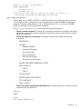
Recommended steps
HP recommends that you run the SRU on a file system volume prior to configuring a migration job
for a thin-provisioned destination LUN. Follow these steps to migrate to a thin-provisioned storage:
1. Run the SRU on the file system volumes that are to be migrated using the MPX200.
2. Follow either the online or offline data migration procedure.
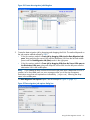
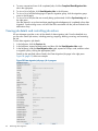
The migration to thin-provisioned storage option (TP settings in HP mpx Manager) has three values:
•
No TP: The destination LUN is not thin-provisioned; this is the default value.
•
Yes, and No Validation: Select this option when the destination LUN is known to be a
thin-provisioned storage and is known to contain all zeroes or is newly created.
•
Yes and TP Validation: Select this option if you are uncertain about the data on the destination
LUN, or if the destination LUN was used earlier for storing any other data. Enabling validation
ensures that no corruptions exist because of stale data on the destination LUN. Enabling
validation creates additional processing overhead. Typically, validation is not required for a
newly created destination LUN for data migration. For remote online and offline data migration,
HP does not recommend thin-provisioning and validation.
DML
The MPX200 uses a DML to support remote migration (asynchronous replication). The DML:
•
Is a critical component to support remote migration.
•
Must be allocated from a highly available storage array on a local SAN.
•
Must be accessible from both MPX200 blades.
•
Must be accessible through multiple paths to each blade.
•
Requires a minimum user capacity of 100GB (recommended), which supports up to 64 remote
migration jobs (active, scheduled, or configured) on a single MPX200 across both blades.
DML size, see Table 5 (page 30), depends on the data change rate and how many concurrent
migration jobs are active. More than 64 remote migration jobs require a minimum of 1GB additional
user capacity for each additional job. Typically, a 164 GB DML can hold 128 DRLs. You can
dynamically add up to eight LUNs in the DML pool. To remove the DML from the pool, ensure that
all remote migration jobs are completed or removed. Each LUN in a DML pool must be smaller
than 2TB.
Migration to a thin-provisioned LUN
29
Table 5 Data migration size
Number of Remote Migration Jobs per MPX200
Minimum Required DML Capacity
64
100 GB
128
164 GB
256
292 GB
512
548 GB
For more information on working with DMLs, refer to “Creating and removing a DML” (page 69)
and “Command line interface” (page 76).
Remote peers
A remote peer identifies the remote router used at a remote site. The remote router establishes
native IP connectivity to perform remote data migration operations. “Using remote peers” (page
51) provides procedures for adding and removing remote peers.
Online remote migration
Remote data migration with the MPX200 uses either Native IP connectivity or FCIP. Because the
MPX200 uses an asynchronous replication method to migrate data online to a remote location,
the router requires a DML, see “Creating and removing a DML” (page 69). The MPX200 uses the
DML to record all the changes during the remote migration process. The DML must be allocated
from any storage array in a local SAN. For DML allocation guidelines, refer to the previous section,
“DML” (page 29).
NOTE: For details about the WAN link between the local and remote sites, refer to the HP
MPX200 Multifunction Router Command Line Interface User Guide. The WAN link test command
helps identify possible WAN issues such as packet drops, jitter, available bandwidth, and so on,
and enables the migration user to adjust the WAN accordingly.
Deploy the MPX200 for data migration at a local location where the source data resides. Before
configuring any remote data migration job, allocate the DML to the MPX200 system from the local
site (source location). To add or delete a DML, see the procedures in “Creating and removing a
DML” (page 69)1. Use one of the following methods to perform remote migration.
Method 1: Using Native IP
Online remote data migration with Native IP has the following objectives:
•
To reduce and simplify the configuration steps required for implementing a remote data
migration.
•
To improve the performance of remote migration using compression.
Configuring the Router and Chassis
Follow these procedures to configure the remote and local routers and chassis for online remote
data migration with Native IP.
To configure the remote router and chassis:
1. Present the LUNs to be used as part of the migration from the destination array to the remote
router and blade VPGs.
2. If the destination array has been moved from the local site to this remote site, add the remote
router and blade VPGs in the same host group as the local router and blade VPGs. This step
ensures that LUNs are visible to the remote router at the same LUN IDs.
3. Zone in the destination array ports with the appropriate VPGs.
4. Ensure that the targets and LUNs are visible on the remote router.
30
Data migration objects
5.
Configure IP addresses for the router’s iSCSI ports by entering an IP address:
•
In mpx Manager, modify the iSCSI Port Information page.
•
In the CLI, issue the set iscsi command (see“set iscsi” (page 110).
To configure the local router and chassis:
1. Take these preliminary steps:
a. Ensure that the local router and chassis have access to the source array.
b. Ensure that the LUNs are visible.
c. Create a data management LUN , see “Creating and removing a DML” (page 69).
d. Configure any potential migration jobs using the destination array (local).
e. If the destination array was initially present at the local site and then moved to a remote
site after the initial copy, ensure that the migration jobs are in a COPY COMPLETE state.
2.
3.
4.
Assign IP addresses to the routers iSCSI ports by issuing the set iscsi command , see “set
iscsi” (page 110).
Ensure IP connectivity between the routers by checking for the following:
•
The local router’s MGMT. port can ping the remote router’s MGMT. port.
•
The local router’s network ports can ping the remote router’s iSCSI ports.
On each local router blade and chassis, issue the remotepeer add command, for details
see “remotepeer” (page 101), and then specify the management port of the remote router. This
step ensures that the remote router has access to the destination array ports and can
communicate using the specified Ethernet ports.
HP recommends the following connections:
5.
6.
7.
•
Blade 1 of the local chassis establishes as the peer Blade 1 of the remote chassis.
•
Blade 2 of the local chassis establishes as the peer Blade 2 of the remote chassis.
Validate the configuration by executing the show remotepeers command, see “show
remotepeers” (page 132).
On each blade, issue the array import command, see “array” (page 77), and then specify
the array to be imported. The imported array is automatically marked as a destination array.
Ensure that the array has been imported successfully by issuing the show array command,
see “show array” (page 112), and then validating the LUN information.
Each blade should see all of the paths that are available on the peer. However, only the paths
that are online on the peer are online locally.
Adding a Migration Job and resuming an existing Migration Job
You can add a remote migration job using an imported array. You can also enable and disable
compression for the migration job.
If a remote migration job was previously running and the array comes online with the LUNs involved
in the migration, the migration job automatically resumes operation.
For an example of using Native IP to add a remote peer, see “remotepeer” (page 101).
To remove an imported array, see “Removing an offline array” (page 69).
Native IP remote migration firewall ports
With Native IP remote migration it may be necessary to open specific ports if a firewall is used in
the network. Table 6 (page 32) describes the ports that are needed to communicate with the MPX
from the mpx management GUI as well as native IP communications between the local and remote
MPX.
Online remote migration
31
Table 6 Native IP remote firewall ports
Description
Direction
Port
Protocol
FTP
Bi-directional
20
TCP/UDP
SSH
Unidirectional
22
TCP
MPX Manager (PortMapper)
Bi-directional
111
TCP/UDP
SNMP
Unidirectional
162
UDP
RPCserver
Bi-directional
617
TCP/UDP
RPCserver
Bi-directional
715
TCP/UDP
RPCserver
Bi-directional
717
TCP/UDP
RPCserver
Bi-directional
729
TCP/UDP
RPCserver
Bi-directional
731
TCP/UDP
RPCserver
Bi-directional
1014
TCP/UDP
iSCSI
Bi-directional
3260
TCP
Method 2: Using a fat pipe between local and remote data center
Scenario: Source array at local data center; destination storage array at remote data center; fat
pipe (a high-capacity WAN link) with dedicated bandwidth for migration between the two locations.
This method requires a minimum of 600 Mbps of dedicated IP link between the two data centers;
the method also requires the change rate be less than 15 MBps.
Best Practices:
•
Allocate a sufficient amount of dedicated bandwidth (used for data migration) between local
and remote data centers. The minimum bandwidth should be four times the data change rate
for round-trip latencies less than 25 ms. For higher round-trip latencies between two sites,
increase the multiplier. For example, if the data change rate for the data actively under
migration is 15 MBps, the minimum dedicated bandwidth should be either 60 MBps or 600
MBps link rate when RTT latencies are less than 25 ms. For a RTT of 100 ms, allocate a 1000
MBps link. HP recommends a dedicated bandwidth of 1000 MBps or greater between two
remote sites. For additional details and bandwidth calculator, see the Data Migration Service
for iSR6200 Planning Guide - ISR654607-00 D.
•
Ensure that dedicated IP bandwidth between two sites is available for data migration throughout
the migration job.
•
When using SAN over WAN, configure a large TCP window size on both SAN over WAN
routers.
For iSCSI migrations, configure a large TCP window on MPX200 iSCSI ports and the target
ports on the iSCSI storage array. Configure TCP window size on the MPX200 by issuing the
CLI command set iscsi. Calculate the typical window size in KB as follows:
•
WAN link bandwidth in MBps × RTT in ms
Divided by the number of iSCSI connections between the MPX200 and iSCSI target port of
the storage array
nl
For example, suppose the available WAN link bandwidth is 100 MBps (1000 MBps), the
RTT is 20 ms, and there are two iSCSI connections between the MPX200 blade and the iSCSI
target ports on the storage array:
(100 × 20) / 2 = 1000 KB TCP window size
Configure 1 MB window size on the MPX200 and iSCSI target port. The MPX200 supports
a maximum TCP window size of 16 MB. An iSCSI target array port may support larger TCP
window sizes.
32
Data migration objects
•
For iSCSI migrations, set the migration I/O size to 64 K.
•
Use only new destination LUNs to select the recommended (and better performing) TP and
No Validation option under TP Settings when creating the migration job.
•
If migrating to a thin-provisioned storage, always allocate destination LUN first. HP does not
recommend the Yes and TP validation option under TP Settings when creating the migration
job.
•
Schedule and start remote migration jobs at off peak hours, so that a small number of dirty
regions are generated, and most of the WAN bandwidth is available to perform the initial
data copy.
•
Follow the guidelines for DML size. Selecting the Yes and TP validation option can result in a
long migration time and may require more bandwidth between two sites.
•
To ensure faster migration, migrate storage for a few servers at a time.
Data scrubbing
The data scrubbing feature provides a method of securely wiping out data on a LUN. This feature
implements several U.S. DoD specifications, including the number of passes and the data pattern
written. Each pass starts at the beginning of the LUN and completes after the I/O to the last LBA
of the job is completed.
The current firmware release provides the following algorithms and passes:
•
ZeroClean: Two passes
•
DOD_5220_22_M: Four passes
•
DOD_5220_22_M_E: Four passes
•
DOD_5220_22_M_ECE: Eight passes
Data scrubbing job attributes
Data scrubbing for data migration includes the following:
•
Source LUN: Indicates the LUN that needs to be scrubbed. The source LUN for a scrubbing
job must not be mapped to a host and must not be part of another job.
•
Job Group: Same as data migration job groups.
•
Scrubbing Algorithm: As noted in the previous section.
•
Scheduling: Same as data migration job scheduling.
•
Scrubbing CurrentPass: Specifies the currently active pass for a scrubbing job.
Data scrubbing protections
Data scrubbing protections include the following:
•
The scrubbing job configuration wizard only shows LUNs that are part of a Source or
Source+Destination array.
•
Job configuration on LUNs that are mapped to an initiator or part of a migration job is not
allowed.
•
LUN presentation of a LUN that is part of a scrubbing job will fail.
•
An additional confirmation is required while configuring a scrubbing job.
Data scrubbing
33
Data scrubbing logs
Data scrubbing jobs generate logs for every user configuration event, as well as for job STARTING,
FAILING or COMPLETION. You can view data scrubbing logs using the same interface as used
for migration logs, see “Viewing system and data migration job logs” (page 63).
Data scrubbing licenses
Data scrubbing license keys are based on an MPX200 blade serial number. The licenses are
shared between two blades in the same MPX200 chassis. The two data-scrubbing license types
are:
•
Capacity-based licenses
•
Array-based licenses
NOTE:
Data scrubbing jobs up to 5 GB currently do not require a license.
Protection
DMS provides data protection against some of the common user errors by enforcing the following
restrictions:
•
An array must have an attribute of either Source, Destination, or Source+Destination to
participate in the migration. When you configure a data migration job, Source LUNs can be
assigned only from an array with the attribute Source (or Source+Destination), and Destination
LUNs can be assigned only from an array with the attribute Destination (or Source+Destination).
Use these attributes properly to avoid errors.
•
A user acknowledgement is required for a data migration job after the job is completed. This
feature provides better accounting and record-keeping for the job. The data migration log
indicates when the job was completed and when you acknowledged the completion status of
the job.
•
For online or offline data migration, after a LUN is configured as a destination LUN for a
specific data migration job, the LUN cannot be configured for a different job until the current
job is acknowledged or removed.
•
DMS detects the normal configuration of Windows OS partitions on the data LUN. Before
fully configuring a data migration job, DMS provides a warning if it detects valid partition
tables on the destination LUN.
Logs
DMS manages the following two log types:
34
•
Migration logs: Migration logs provide a detailed history of each data migration job. The job
history contains information such as the start and end time of the job, source and destination
LUNs and arrays, size of the job, total time consumed for the job, and so on. Using HP mpx
Manager, you can export the migration logs out of the MPX200. You can open this file with
a spreadsheet application such as Microsoft Excel and use it as a data migration task report.
HP highly recommends that you save migration logs after the data migration job is completed
and cleared from the MPX200. This task provides a record of every data migration job and
makes it easier to differentiate between them.
•
System logs: System logs primarily record events, errors, and configuration changes, and can
be used for troubleshooting.
Data migration objects
Users
The MPX200 supports two types of users:
•
Administrative user (admin): For managing the MPX200, you must be in an administrative
session. The default password for the administrator is config.
•
Data migration user (miguser): This user session is required to configure migration-related
activities. The default password is migration.
Host
A host is a logical construct consisting of one or more initiator ports for one or more protocols.
The host simplifies the configuration process and prevents configuration errors during LUN masking
by:
•
Representing a single server with one or many FC or iSCSI ports.
•
Representing one or many servers, each with one or many FC or iSCSI ports. Servers are used
in a cluster environment where the same LUNs must be presented to multiple servers and cluster
hosts.
•
Being available across the blades of a chassis.
Host attributes include the following:
•
Symbolic name, which must be unique chassis-wide, identifies the host.
•
OS type indicates the current OS type from initiator ports to be moved to the host. The initiator
ports inherit the OS type from the host. A change in the host OS type reflects in all the initiator
ports that are part of the host.
•
Host state is either online (one or more initiator ports are logged in) or offline (all initiator
ports are logged out).
NOTE: If the host has LUN mapping on its initiators, the mapping to the host is removed when
you remove all the initiators.
A host without initiators cannot be mapped to LUNs.
Users
35
4 Data migration licenses
This chapter provides information on data migration licenses including license types, license
installation, and license use.
Types of data migration licenses
Data migration license keys are based on an MPX200 blade serial number. The licenses are shared
between two blades in the same MPX200 chassis. The two types of data migration licenses are
capacity-based and array-based.
Capacity-based licenses
Capacity-based licenses allow you to migrate data up to a specific limit designated by the applied
license key. This type of license is available in variants of 1 TB and 5 TB capacities, which can be
consumed by one or more migration jobs that you create. Every time you configure a data migration
job, the available capacity is reduced by an amount equivalent to the size of the source LUN being
migrated. The MPX200 does not allow you to add migration jobs when the job size exceeds
available migration licenses.
Array-based licenses
For large storage arrays, array-based licenses are more cost effective than Capacity-based licenses.
Array-based licenses allow you to migrate unlimited amounts of data to and from the specific array
that is licensed. This license SKU is available as a single-array license SKU. You may purchase
multiple single-array license SKUs, generate license keys, and load them on the MPX200. Each
single-array license can be tied to a specific array. The licensed array may be used as either a
source or destination array while configuring jobs for data migration.
Array-based licenses allow you to migrate data in and out of the specified licensed array. For
example, consolidating three or four source arrays onto a single destination array requires only
one single-array license on the destination array.
You would consume multiple single-array licenses under the following conditions:
•
Each single array license is valid for one MPX200 chassis. If you have storage arrays with a
large number of ports (for example, EMC DMX, HP-XP, and so on) and want to use multiple
MPX200s for data migration, you must purchase multiple single-array license keys for each
MPX200.
•
If you present one set of LUNs to the MPX200 from the same array from one set of storage
array ports, and also present a second set of LUNs to the same MPX200 from the same array
from a different set of storage array ports, the MPX200 detects the LUNs as two different
arrays. You must purchase multiple single-array licenses for the same storage array.
Types of data scrubbing licenses
Data scrubbing license keys also include capacity-based and array-based licenses.
Capacity-based licenses
Capacity-based data scrubbing licenses allow you to scrub the data up to the licensed capacity.
A capacity-based license is consumed based on the size of the data LUN being scrubbed. For
example, if you have a 5 TB data scrubbing license and scrub a 500 GB LUN, 500 GB of the
license is consumed and 4,500 GB of the license remains available for future use.
Array-based licenses
Array-based data scrubbing licenses allow you to scrub all LUNs within that array, regardless of
array capacity. An array-based license is consumed when it is allocated to a specific array.
36
Data migration licenses
Installing a data migration license key
Follow this procedure to install a data migration license key using HP mpx Manager.
To install a data migration license key:
1. In the HP mpx Manager main window, click the Router tab in the left pane.
2. In the left pane, click Router MPX200, and then select the blade on which to install the license
key.
NOTE: The License key is generated from the blade serial number. Install the license on the
blade used to generate the key. The license is then shared by both blades.
3.
4.
In the right pane, click the Features tab.
On the Features page under License Information, click Add, as shown in Figure 13 (page 37).
Figure 13 Features page: license information
The New License Key dialog box opens.
5.
Enter a valid DM license key, and then click OK.
The Add license dialog box indicates the success of the license add operation:
6.
7.
Click OK to close the verification dialog box.
Verify that the newly added key appears in the list of keys on the Features page, as shown
in Figure 13 (page 37).
Applying an array-based license to a specific array
You can apply an array-based license to a specified storage array using either HP mpx Manager
or the CLI. If you have purchased array-based licenses and installed the licenses in the MPX200,
follow these steps to license a specific array for data migration. For every array that is licensed,
one license is consumed.
To apply an array-based license to a specific array in the GUI:
Installing a data migration license key
37
1.
2.
3.
4.
In the left pane of the HP mpx Manager main window, click the Router tab.
On the Wizards menu, click License an Array.
In the left pane under Arrays, click the name of the FC or iSCSI array to which to apply the
license.
In the License Array dialog box, select the array for which you want to apply the license, see
Figure 14 (page 38), and then click OK.
Figure 14 License Array dialog box
The Information page for the selected array now shows Licensed in the Array License field, see
Figure 15 (page 39).
38
Data migration licenses
Figure 15 Information page showing array is licensed
Viewing data migration and scrubbing license usage
You can view the usage for the data migration and scrubbing licenses from either HP mpx Manager
or the CLI. In addition, you can create a report containing the license usage information.
Follow these procedures to view the usage of data migration and scrubbing licenses in the GUI;
to view the licenses in the CLI, see “show migration_usage” (page 129). You can view license usage
for either the chassis or a blade.
To view data migration license usage for the chassis:
1. In the left pane of the HP mpx Manager main window, click the Router tab.
2. In the left pane, select the router name.
3. Click the License Info tab.
License usage appears on the License Info page, as shown in Figure 16 (page 40).
Viewing data migration and scrubbing license usage
39
Figure 16 License info for the chassis
To view data migration license usage for the blade:
1. In the left pane of the HP mpx Manager main window, click the Services tab.
2. In the left pane, under Router MPXxxx, select a blade node.
License usage appears on the License Info page, as shown in Figure 17 (page 40).
Figure 17 Data migration info for a blade
40
Data migration licenses
5 Performing data migration
This chapter provides a number of procedures for configuring and managing data migration using
DMS.
Typical data migration process
Table 7 (page 41) and Table 8 (page 42) show the MPX200 data migration process flow by
category and activity, and references the appropriate section for each.
Table 7 Online data migration process flow
Category
Pre-migration
Activity
For more information, see…
1. Plan for data migration.
Data Migration Service for MPX200 Planning
Guide
2. At the start of the project, clear the migration
logs.
“Viewing system and data migration job logs”
(page 63)
3. Verify the pre-installed data migration license “Installing a data migration license key” (page
or install a license key, then apply the
37) and “Applying an array-based license to a
array-based license key, if an array-based
specific array” (page 37)
migration license will be consumed for this
project. Otherwise, a per-TB license is used
automatically.
4. Configure the FC fabric.
“Configuring the fabric” (page 42)
5. Provide the MPX200 access to LUNs from
source and destination arrays.
“Presenting LUNs to the MPX200” (page 43)
6. Discover arrays and set array properties.
“Setting array properties” (page 53)
7. Configure automatic failover for high
availability.
“Job failover and failback” (page 23)
8. Define user groups.
“Creating a data migration job group” (page
55)
9. Map source array LUNs to one or more hosts. “Presenting LUNs to the server for online data
For online remote migration, also create a data migration” (page 46)
management LUN.
10. Create presented targets to map source array “Step 2: Create presented targets” (page 47)
target ports with MPX200 Fibre Channel ports.
11. Insert the MPX200 in the server data path
and zone out direct paths from servers to the
source storage array.
“Step 1: Inserting the MPX200 in the server data
path for online data migration” (page 46)
Configure
migration jobs
12. Configure and validate data migration jobs. “Using the data migration wizard” (page 55)
Migrate and
monitor
13. For data migration jobs that are scheduled
for a delayed start, specify the start time for the
job.
“Starting serial scheduled jobs” (page 60)
14.Monitor data migration jobs.
“Viewing job details and controlling job actions”
(page 62)
15. Acknowledge the data migration jobs.
“Acknowledging a data migration job” (page
67)
16. Export data migration logs.
“Viewing system and data migration job logs”
(page 63)
Post-migration
Typical data migration process
41
Table 7 Online data migration process flow (continued)
Category
Activity
For more information, see…
17. Remove arrays from persistence.
“Removing an offline array” (page 69)
18. Check license usage.
“Viewing data migration and scrubbing license
usage” (page 39)
Table 8 Offline data migration process flow
Category
Activity
For more information, see…
Pre-migration
1. Plan for data migration.
Data Migration Service for MPX200 Planning
Guide
2. At the start of the project, clear the migration
logs.
“Viewing system and data migration job logs”
(page 63)
3. Verify the pre-installed data migration license “Installing a data migration license key” (page
or install a license key, then apply the
37) and “Applying an array-based license to a
array-based license key, if an array-based
specific array” (page 37)
migration license will be consumed for this
project. Otherwise, a per-TB license is used
automatically.
4. Configure the FC fabric.
“Configuring the fabric” (page 42)
5. Provide the MPX200 access to LUNs from
source and destination arrays.
“Presenting LUNs to the MPX200” (page 43)
6. Discover arrays and set array properties.
“Setting array properties” (page 53)
7. Configure automatic failover for high
availability.
“Job failover and failback” (page 23)
8. Define user groups.
“Creating a data migration job group” (page
55)
Configure
migration jobs
9. Configure and validate data migration jobs.
“Using the data migration wizard” (page 55)
Migrate and
monitor
10. Ensure that the server no longer has access
to source LUNs.
“Data migration configuration” (page 11)
11. For data migration jobs that are scheduled
for a delayed start, specify the start time for the
job.
“Starting serial scheduled jobs” (page 60)
12.Monitor data migration jobs.
“Viewing job details and controlling job actions”
(page 62)
13. Acknowledge the data migration jobs.
“Acknowledging a data migration job” (page
67)
14. Export data migration logs.
“Viewing system and data migration job logs”
(page 63)
15. Remove arrays from persistence.
“Removing an offline array” (page 69)
16. Check license usage.
“Viewing data migration and scrubbing license
usage” (page 39)
Configuring the fabric
Because MPX200 online data migration presents multiple virtual FC ports to each physical FC port,
enable NPIV support on the FC switches. If the FC switches (older 2 Gb FC switches) do not support
NPIV, or if you do allow the switch to be configured with NPIV support, enable loop mode support
on an FC switch port, then configure the MPX200 FC ports in loop-preferred or loop-only mode.
The default is loop-preferred.
42
Performing data migration
If NPIV is not supported or not enabled and if the FC switch port cannot be configured to support
loop mode, configure MPX200 ports in point-to-point only mode. In point-to-point only configuration
of MPX200 FC ports, you can perform only offline migration. NPIV and enabling NPIV support
are not options.
Table 9 (page 43) lists the behavior of MPX200 FC ports as determined by the configuration of
various FC switch ports, where:
•
The Connect and Connect (loop mode) settings are appropriate for online data migration.
•
The Connect (offline migration only) setting is appropriate for offline data migration.
•
The No connect setting indicates that the link does not come up unless you change the MPX200
FC port or switch port setting.
Table 9 FC port settings
FC switch port setting
MPX200 FC
port setting
NPIV supported and NPIV enabled
NPIV not supported or NPIV disabled
F_Port1
and FL_Port2
(P2P3 or loop)
F_Port
(P2P only)
FL_Port
(loop only)
F_Port and
FL_Port
(P2P or loop)
P2P only
Connect
Connect
No connect
Connect
Connect
No connect
(offline
(offline
migration only) migration only)
Auto (default)
Connect
Connect
Connect
(loop mode)
Connect
(loop mode)
No connect
nl
Connect (loop
mode)
Connect (loop
mode)
No connect
nl
Loop only
Connect (loop
mode)
1
Fabric port
2
Fabric loop port
3
Point-to-point
nl
No connect
nl
nl
F_Port
(P2P only)
nl
nl
FL_Port
(loop only)
nl
Connect
(loop mode)
nl
Connect (loop
mode)
Presenting LUNs to the MPX200
Data migration requires that LUNs from both the source and destination storage arrays be presented
to the MPX200 from either FC arrays or iSCSI arrays.
When presenting LUNs to the MPX200 FC ports, you must not present LUNs from different arrays
using the same World Wide Unique LUN Name. The MPX200 uses the WWULN of a presented
LUN to determine the number of paths available to a specific array entry. Adding LUNs from
different arrays using the same WWULN as an existing presented LUN to the MPX200 prevents
the MPX200 from creating a new array entry.
The following example shows typical MPX200 LUN information:
LUN Information
_______________
WWULN 60:05:08:b4:00:0b:15:a2:00:00:b0:00:00:12:00:00
Serial Number P5512G39SWN0NE
LUN Number 3
VendorId HP
ProductId HSV300
ProdRevLevel 0005
Portal 0
Lun Size 102400 MB
Lun State Online
Presenting LUNs to the MPX200
43
Do not modify the WWULN of a LUN that is to be presented to the MPX200. To create a WWULN
specific to that array, use regular LUN creation procedures.
LUN presentation from FC arrays
This section provides the procedures for presenting LUNs and discovering FC storage arrays for
data migration.
To present source and destination LUNs from FC arrays:
1. Zone in source array controller ports with appropriate MPX200 VPGs (for more information,
see “VPG” (page 24). Create and activate Zone 3 and Zone 4 as shown in Figure 5 (page
12) such that each router blade can access all ports on source array controllers A and B.
2. Zone in destination array controller ports with MPX200 FC ports. Create and activate Zone
5 and Zone 6 as shown in Figure 4 (page 12) such that each router blade can access all
ports on destination array controllers A and B.
3. Present LUNs from both the source and destination array to the MPX200 as follows:
a.
Register the following router FC WWPNs from the same VPG as a single “host entry” in
the storage array:
nl
nl
BL1–FC1–VPG1
BL1–FC2–VPG1
BL2–FC1–VPG1
BL2–FC2–VPG1
nl
nl
nl
For more information on configuring VPGs on an FC array, see the chapter on
configuration in the HP MPX200 Multifunction Router User Guide.
b.
c.
d.
In the array management utility, set the VPG host type to either Windows or HP-UX. For
3PAR router host entry set Persona to 2.
For online migration with an HP-UX host, register the router’s VPG host with the same host
platform options as used by the actual HP-UX host under migration. To determine these
options, refer to the array management software where the HP-UX host is registered,
which provides access to the storage LUNs.
Present the LUNs (associated with the server) to the router. If you are migrating multiple
servers at the same time using the same MPX200, and different LUNs are presented from
the storage array using the same LUN IDs to different servers, then present the LUNs to
the MPX200 at any ID. While presenting the LUN to the server through the MPX200, use
the LUN remapping feature.
NOTE: For multiple server migration, assign LUNs to these host as the same LUN ID. For
example, a Windows host can see a LUN at ID 1 and a Linux host can see a different LUN
at ID 1. You can assign these LUNs to the MPX200 at any LUN ID. Use the LUN remapping
feature to present a LUN at the same LUN ID to multiple hosts (both Windows and Linux, in
this example) through the MPX200. For more information, refer to the Data Migration Service
for MPX200 Planning Guide.
4.
44
(Optional) To discover the newly presented LUNs and form new arrays, if required, follow
these steps:
a. In the left pane of HP mpx Manager, click the Router tab.
b. Right-click the appropriate blade.
c. On the shortcut menu, click Rescan.
Performing data migration
NOTE: The MPX200 supports a maximum of four VPGs. To expose more than 256 LUNs
(numbered from 0 to 255) from any FC storage array that allows no more than 255 LUNs be
presented per host, you can enable additional VPGs in the MPX200 blades. To present up to
1,024 LUNs (4×256) from the same array to the MPX200, repeat the preceding steps for each
VPG.
In addition, the current firmware supports 1,024 LUNs per VPG for a total of 4,096 (4×1024)
LUNs mapped to the MPX200 if all VPGs are enabled. If the array side is limited to mapping a
maximum of 256 LUNs to a single host (for example, a host router virtual port), you can map
1,024 LUNs to the MPX200 through four VPGs.
For more information on LUN presentation to the MPX200 through different vendor arrays, refer
to the Data Migration Service for MPX200 Planning Guide.
LUN presentation from iSCSI arrays
This section provides the procedures for presenting LUNs and discovering iSCSI storage arrays for
data migration.
To present source and destination LUNs from iSCSI arrays:
1. Determine the iSCSI initiator name of each blade by entering the show iscsi command;
see “show iscsi” (page 119).
2. Using the iSCSI array management utility, register the router as a host using the IQN of the
iSCSI port, and then assign LUNs to this host.
NOTE: Some iSCSI arrays require pre-registered hosts for the iscsi discover command
to succeed. For these arrays, manually create a host with the IQN of the router iSCSI port
before you execute the command.
3.
4.
5.
Using the CLI, discover iSCSI storage arrays by entering the iscsi discover command,
see “iscsi” (page 87).
List the discovered iSCSI targets, as well any FC targets (if present), by issuing the show
targets command, see “show targets” (page 134).
Log into the iSCSI target by entering the iscsi login command, see “iscsi” (page 87).
After successful iSCSI login, the iSCSI target comes online.
NOTE: If the iSCSI storage array supports it, you can establish multiple connections per
session using multiple GbE ports on the same router blade and storage array.
6.
(Optional) To discover the newly presented LUNs and form the new arrays, if required, follow
these steps:
a. In the left pane of HP mpx Manager, click the Router tab.
b. Right-click the appropriate array or target.
c. On the shortcut menu, click Rescan.
Rescanning Targets
To see if one or more data LUNs are exposed to the router ports from the target, you can rescan
the target ports. A rescan may cause the router to create an array entity for the target ports through
which the router is able to see data LUNs.
To rescan targets:
1. In the HP mpx Manager left pane, right-click the FC Discovered Targets node.
Rescanning Targets
45
2.
From the shortcut menu, click Rescan. In the left pane under the FC Arrays node, the
newly-generated array entity is shown. Alternately, you can click Refresh two or three times
to rescan the targets and generate the array entity for targets that are exposing LUNs to the
router.
Creating a data migration job group
Follow these steps to create a data migration job group in HP Storage mpx Manager:
1. In the left pane, click the Services tab to open the Services page.
By default, the MPX200 shows Group 0 created under the Data Migration Jobs item in the left
pane.
2.
3.
4.
In the left pane, click Data Migration Jobs, and then on the shortcut menu, click Add Group.
(Or on the Wizards menu, click Add Group.)
In the Create New Group dialog box, enter a group name that you want to assign to administer
a set of data migration jobs, and then click OK.
In the Data Migration Security Check dialog box, enter the data migration user password
(default is migration), and then click OK.
Presenting LUNs to the server for online data migration
For online data migration, you need to create access to all LUNs associated with the server or
servers through the router, and you must eliminate direct access from the server to the storage
array.
Follow these basic steps to present the LUNs from the MPX200 to the server:
“Step 1: Inserting the MPX200 in the server data path for online data migration” (page 46)
“Step 2: Create presented targets” (page 47)
“Step 3: Zone in presented targets with initiator ports” (page 48)
Step 1: Inserting the MPX200 in the server data path for online data migration
Map the initiators to the LUN and create presented targets (virtual ports) associated with the source
array target ports and the VPG. For more information, see “Presented targets” (page 25).
HP recommends that you create the presented target on the same FC port of the MPX200 on which
the source array port is discovered. Typically, FC zoning is set up such that one source array port
is discovered through one FC port (one or more VPGs) of the MPX200. If the same source array
target port is discovered through multiple FC ports (on the same VPG) of the MPX200, create only
one presented target port across both blades of the MPX200.
To present source array LUNs to the initiator for online data migration:
46
Performing data migration
1.
Use either the HP mpx Manager or the CLI to create a presented target:
•
In HP mpx Manager, use the Target Presentation/LUN Mapping Wizard to map LUNs
to initiators. The LUNs are presented to the initiators at the ID that is available on the
MPX200. If the LUN needs to be presented to the initiator with a different LUN ID, select
the wizard’s LUN Remap option as the Presentation Type.
Because HP mpx Manager performs an array-based LUN presentation, the LUN is
presented to an initiator through all of the discovered target ports. The visibility of a LUN
through a target on the initiator depends on your zoning configuration.
•
In the CLI, issue the lunmask add command, see “lunmask” (page 90) and select the
appropriate target and portal. For example:
◦
HBA1 > SA1 > LUN1 > BL1 FC1 VPG1 creates presented target PT1 (SA1 +
VPG1)
◦
HBA2 > SB2 > LUN1 > BL1 FC2 VPG1 creates presented target PT4 (SB2 +
VPG1)
2.
(Optional) To discover the newly presented LUNs and form the new arrays, if required, follow
these steps:
a. In the left pane of HP mpx Manager, click the Router tab.
b. Right-click the appropriate target or array.
c. On the shortcut menu, click Rescan.
3.
Repeat the preceding steps for the second blade so that the LUN is accessible to the server
through both blades.
Step 2: Create presented targets
If the presented target associated with the source array target port and the VPG does not exist,
you must create one using HP mpx Manager or the CLI.
Creating a presented target in the GUI
Use the Target Map Wizard to add a presented target for each source array target port for the
VPG from which LUNs are being mapped to the host. Ensure that you create only one presented
target (associated with source array target port and the VPG) across both blades and that you
include the global target presentation details. The Target Map Wizard provides two methods to
create presented targets:
•
Global presentation. Use this method when the LUN remapping option is used to map LUNs
to initiators. Global presentation creates a single presented target for all VPGs (if VPGs are
enabled).
•
VPG-based presentation. Use this method when the LUN mapping option is used with Target
Presentation/LUN Mapping Wizard. Select a VPG to create a presented target. LUNs presented
through the specified VPG are presented through this presented target. For more information,
see “Presented targets” (page 25).
You can use the iSCSI Target Global Present Wizard to manually or automatically create a global
presentation for iSCSI targets. With the automatic option, the utility creates the presentation using
the WWPN reserved for the system-generated target map. With the manual option, you enter a
WWPN for the target map per portal to create a single global presentation for all iSCSI targets.
Creating a presented target in the CLI
As another option, follow these steps to create a configuration using the targetmap command
in the CLI, see “targetmap” (page 137).
To create presented targets in the CLI:
Presenting LUNs to the server for online data migration
47
1.
Configure the hosts as follows:
Host 1:
1. Present LUNs A, B, and C to the host as LUN IDs 1, 2, and 3.
2. Present LUNs A, B, and C to the MPX200 VPG1 as LUNs 1, 2, and 3.
Host 2:
1. Present LUNs D, E, and F to the host as LUN ID 5, 6, and 7.
2. Present LUNs D, E, and F to the MPX200 VPG1 as LUN 5, 6, and 7.
Host 3:
1. Present LUNs G, H, and I to the host as LUN ID 1, 2, and 3.
2. Present LUNs G, H, and I to the MPX200 VPG2 as LUN ID 1, 2, and 3.
This configuration enables MPX200 VPG1 and VPG2 to see all four source array target ports
through both blades.
2.
3.
Create the following presented targets when presenting the LUNs to Host 1 or Host 2:
•
PT2 is SA2+VPG1
•
PT2 is SA2+VPG1
•
PT3 is SB1+VPG1
•
PT4 is SB1+VPG1
Create the following additional presented targets when presenting LUNs to Host 3:
•
PT4 is SA1+VPG2
•
PT5 is SA2+VPG2
•
PT6 is SB1+VPG2
•
PT7 is SB1+VPG2
Step 3: Zone in presented targets with initiator ports
Zone in appropriate presented targets with initiator ports on the server. After completing LUN and
target presentation from the MPX200 to the server, follow these recommended steps to insert the
MPX200 in the data path and remove direct access between the host and storage array. Depending
on the source array type (active-active or active-passive) and configuration (cluster or noncluster),
these steps may vary.
NOTE: For information about online insertion of the MPX200 in the data path in a cluster
configuration, see the HP application note, MPX200 Data Migration for Cluster Configurations.
You can use either one of the methods in this section for single server configuration. In addition,
refer to the following:
•
For a description of FC zones, Figure 4 (page 12).
•
For operating system specific details, refer to “Configuring the data path through MPX200
for online data migration” (page 152).
Zoning in presented targets: Method 1
Source array: active-passive or active-active
Single server configuration: noncluster
This method represents a conservative approach. In this method, you remove one direct path from
the source array, and then enable an equivalent path from the MPX200. This method requires
multiple zoning steps:
1. Remove SA1 from Zone 1, and then validate the I/O failover to another path.
48
Performing data migration
2.
3.
4.
5.
6.
7.
8.
Activate Zone 9, and then validate the new path.
Remove SB1 from Zone 1, and then validate I/O failover to another path.
Activate Zone 11, and then validate the new path.
Remove SA2 from Zone 2, and then validate I/O failover to another path.
Activate Zone 10, and then validate the new path.
Remove SB2 from Zone 2, and then validate I/O failover to another path.
Activate Zone 12, and then validate the new path.
Zoning in presented targets: Method 2
Source array: active-active
Single server configuration: noncluster
Use this method when dealing with arrays that support active-active configuration, where LUNs
are accessible simultaneously through both controllers. Such LUNs have paths that are either
active-optimized or active-unoptimized. Most 4 Gb FC arrays support such configurations, as do
2 Gb FC arrays from the EMC Symmetrix family, HP XP family, and Hitachi Data Systems USP and
9900 families.
1. Activate Zone 9, Zone 10, Zone 11, and Zone 12.
2. Validate the new paths.
The paths through MPX200 are enabled.
3. Remove Zone 1 and Zone 2.
Direct paths are removed.
nl
nl
Mapping LUNs to initiators
HP mpx Manager provides the Target Presentation/LUN Mapping Wizard to map FC and iSCSI
initiators to LUNs for online data migration. This mapping provides the access for the LUN to the
host from the router through a presented virtual target. Mapping is required as a part of the process
of inserting the router in the host I/O path. You must ensure that the entire host I/O is routed by
the router, and that there is no direct access to any source controller ports from the host during
migration.
NOTE:
•
LUN mapping is required only for online data migration for FC and iSCSI initiators. LUN
mapping is not required for offline data migration.
•
For HP-UX initiators, set the host type to HP-UX in the MPX200. For all other initiators, leave
the host type set to Windows, the default.
•
For arrays that have a dedicated controller LUN (for example, LUN-0 on HP EVA arrays),
ensure that LUN-0 is also presented to the FC initiators hosts with the actual data LUNs.
To map an initiator to a LUN:
1. On the Wizards menu, click LUN Presentation Wizard to open the Target Presentation/LUN
Mapping Wizard.
2. The LUN Presentation Type window prompts you to select a presentation type. Select one of
the following options, and then click Next.
3.
•
LUN Presentation
•
LUN Remap
On the Select the Initiators for LUN Presentation window, select an initiator, and then click
Next.
Mapping LUNs to initiators
49
4.
On the LUN Selection window, select one or more LUNs for the selected virtual port group
node, and then click Next, or use the LUN remapping feature to remap a LUN to a different
ID.
On the Suggestion window, the router automatically detects the portals through which the
array target ports are accessible. HP recommends that you present a single source, array
target port, and VPG only once across both blades. Figure 4 (page 12) shows that when
source arrays ports SA1, SA2, SA3, and SA4 are discovered on VPG1, only one corresponding
presented target is created on PT-SA1, PT-SA2, PT-SA3, and PT-SA4. Although portal selection
is not mandatory for LUN presentation, this window suggests that you map targets on the
respective FC portals to make the LUNs available to the host.
NOTE: The Suggestion window appears only when there is no existing mapping. This
window does not appear if a target map already exists as part of a previous LUN presentation
through this array.
5.
On the Confirm Changes window, review the LUN mapping, and then click Next.
The LUN Masking Configuration Status opens, and the Security Check dialog box prompts
you to enter the administrative password.
6.
7.
Type the admin password, and then click OK.
On the LUN Masking Configuration Status window, review the results of the target ports
presented for the selected initiators, and then click Finish.
Mapping LUNs to hosts
The Host LUN Presentation Wizard allows mapping LUNs from the source storage array to all the
initiator ports configured as a single host, eliminating the requirement for selecting multiple initiators
with Initiator LUN mapping. Unlike Initiator LUN mapping, Host LUN mapping is done for both
the blades in a single operation.
This mapping provides access for the LUN to the host from the router through a presented virtual
target. Mapping is required as a part of the online migration process of inserting the router in the
host I/O path. You must ensure that the entire host I/O is routed by the router, and that there is
no direct access to any source controller ports from the host during migration.
NOTE: LUN mapping is required only for online data migration for FC and iSCSI initiators. LUN
mapping is not required for offline data migration.
For HP-UX initiators, set the host type to HP-UX in the MPX200. For all other initiators, leave the
host type set to Windows, the default.
For arrays that have a dedicated controller LUN (for example, LUN-0 on HP EVA arrays), ensure
that LUN-0 is also presented to the FC initiators hosts with the actual data LUNs.
To map a source LUN to a Host:
1. On the Wizards menu, select Host LUN Presentation Wizard.
2. If prompted to select a blade, click Blade 1 on which to perform the mapping as Host. However,
Host LUN presentation is a chassis level feature, so it is going to create LUN mapping on both
blades.
3. On the LUN Presentation Type window, select LUN Remap and then click Next.
NOTE: HP recommends that you use the LUN Remap option during LUN Presentation. This
makes it mandatory for the user to choose the Global option when creating PresentedTarget
Maps. The Global Target map eliminates the need to create a presented target for each
VPgroup and reduces the number of maps required.
4.
50
On the Select the Host for LUN Presentation window, select the host that needs to be assigned
LUNs, and then click Next.
Performing data migration
5.
On the LUN Selection window, expand the array and VP groups, select one or more LUNs to
present, and then click Next.
6. On the Assign LUN ID window, a default LUN ID is shown corresponding to the Discovered
LUN ID presented to the router from the storage array in the Present LUN ID column. A new
LUN ID may be presented to the Host by editing the Present LUN ID column. Click Next to
continue
7. On the Suggestion for Target Map Presentation window, review the information, and then
either click Next to continue or click Back to change your selections.
8. On the Confirm Changes window, review the information, and then click Next.
9. On the Security Check dialog box, enter the admin password, and then click Next.
10. On the LUN Masking Configuration Status window, review the results of the target presented
for the selected host, then click Finish.
Using remote peers
Use remote peers to create a connection between a local and a remote router using the MPX200’s
iSCSI port. This feature uses the Native IP method for accessing remote MPX200 information on
the local MPX200. Use a remote peer when the destination array is located at a different geographic
location from the source array.
To add a remote peer:
1. On the Wizards menu, click Add Remote Peer Wizard.
2. In the Select Usage dialog box, select Data Migration as the peer type, and then click OK.
The Add Remote Peer Wizard opens and prompts you to Enter the remote Router’s IP address.
3. In the IPv4 Address box, type the IP address of the management port for the remote peer router
to be added, and then click Next.
4. In the Select Remote iSCSI IP dialog box, select an iSCSI IP address from the remote peer
router, and then click OK, or click Cancel to abandon the remote iSCSI address selection.
5. In the Select Local iSCSI IP dialog box, select an iSCSI IP address from the local router, and
then click OK, or click Cancel to abandon the local iSCSI address selection.
6. In the Remote Router Admin Password dialog box, type the administrator password for the
remote router, and then click OK.
Using remote peers
51
7.
In the Add Remote Router Status window, review the remote router configuration, and then
click Finish.
Figure 18 Add Remote Router Status window
8.
To view information about the newly added remote peer router, select the remote peer node
in the router tree. Figure 19 (page 52) shows an example.
Figure 19 View remote peer router information
To remove a remote peer:
1. On the Wizards menu, click Remove Remote Peer Wizard. The Remove Remote Peer Wizard
opens and prompts you to Select a remote router to unmap.
2. Select the check box for the remote router that you want to remove, and then click OK.
3. In the LOCAL Router Admin Password dialog box, type the administrator password for the
remote router, and then click OK.
Importing a remote array
For remote migration using the Native IP method, create a remote peer connection, and then import
the remote array to the local router. Importing a remote array presents the remote array’s LUNs
on the local router so that you can use them as destination LUNs for data migration.
To import a remote array:
1. On the Wizards menu, click Import Remote Array Wizard, and if prompted, select a blade.
The Import Remote Array Wizard opens and lists the known remote arrays.
2.
3.
52
Under Import Remote Array, expand the IP address tree.
Select the check box next to the name of the array name to be imported, and then click OK.
Performing data migration
Figure 20 Add imported array
4.
In the Import Remote Array Security Check dialog box, type the miguser password, and then
click OK.
Imported arrays are identified under the Array node in the Router Tree by the text [Imported].
Figure 21 View imported array
Setting array properties
HP mpx Manager enables you to configure the target type and bandwidth, and to enable load
balancing, for each storage array used in data migration.
To set array properties:
1. In the left pane, click Arrays to view all the FC storage arrays detected by the MPX200.
2. Click the storage array you want to use as the source array.
The Information page in the right pane displays all the properties currently set for the selected
array. Figure 22 (page 54) shows an example.
Setting array properties
53
Figure 22 Information page: setting array properties
3.
4.
(Optional) In the Symbolic Name box, enter a user-friendly array name.
From the Target Type list, select Source.
NOTE:
5.
Array bandwidth is only displayed and editable if the array target type is Source.
From the Array Bandwidth list, click one of the following values:
•
Slow (50 MB/s)
•
Medium (200 MB/s)
•
Fast (1600 MB/s)
•
User Defined
•
Max Available
6.
If you select User Defined, enter a value between 50 and 1600 in the User Defined Bandwidth
(MB/s) box. By default, the MPX200 uses all available bandwidth; the minimum bandwidth
required for data migration is 50 Mbps.
7. For Load Balancing, click either Enabled or Disabled. By default, load balancing is enabled.
8. For Maximum Concurrent I/O, specify the maximum quantity of data migration I/Os that can
be issued concurrently to the source storage array.
9. Select Enable I/O Pacing to control automatic throttling and pacing of migration I/O. I/O
pacing is used during data migration to limit I/O on a single array from consuming the
MPX200's bandwidth, and to maximize host and migration I/O performance.
10. For LUN Info Display, specify whether the array’s LUNs are identified by LUN ID, WWULN,
or Serial Number.
11. To save your changes, click Save.
12. If the Data Migration Security Check dialog box opens, enter the administrative password.
(The default password is migration.)
HP mpx Manager displays an informative message indicating that the array properties have
changed.
13. Click OK to close the message box.
14. To apply the changes and update the window before changing other array properties, click
Refresh.
54
Performing data migration
Creating a data migration job group
Follow these steps to create a data migration job group in HP mpx Manager.
To create a data migration job group:
1. In the left pane, click the Services tab to open the Services page.
By default, the MPX200 shows Group 0 created under the Data Migration Jobs item in the
left pane.
2.
3.
4.
In the left pane, right-click Data Migration Jobs, and then on the shortcut menu, click Add
Group. (Or on the Wizards menu, click Add Group.)
In the Create New Group dialog box, enter a group name that you want to assign to administer
a set of data migration jobs, and then click OK.
In the Data Migration Security Check dialog box, enter the data migration user password
(default is migration), and then click OK.
Using the data migration wizard
The data migration wizard helps simplify the configuration and scheduling of both individual and
batches of data migration jobs. The following sections provide wizard details on starting and using
the data migration wizard to schedule individual and batch migration jobs.
Starting the data migration wizard
Follow these steps to start the data migration wizard, and then proceed with scheduling either an
individual or batch data migration job.
CAUTION: Before starting an offline data migration job, ensure that the host has no direct access
to the source LUN. For online data migration, ensure that only router paths are available to the
host.
Before acknowledging a data migration job, ensure that the source and destination LUNs are not
presented to any host.
To start the data migration wizard:
1. Start HP mpx Manager and connect to the MPX200 by providing the IP address of the MPX200.
2. Start the data migration wizard using one of these methods:
3.
4.
5.
6.
•
On the Wizards menu, click Configure Migration Jobs.
•
In the left pane, open the Services page, right-click the Data Migration Jobs node, and
then click Configure Migration Jobs.
If the Data Migration Security Check dialog box appears, enter the data migration user
password (default is migration), and then click OK.
If the Confirm System Time Update dialog box appears warning you of a 30 minute or more
discrepancy between the host's time and the system time, do one of the following:
•
Click Yes to update the system time to match the host time.
•
Click No to keep the current system time. Note that a time discrepancy can affect job
scheduling.
If the Confirm LUN Filtering dialog box appears, click Yes to have HP mpx Manager hide
LUNs belonging to existing data migration jobs, or No to show all LUNs.
In the Create Data Migration Job dialog box, click Options.
Creating a data migration job group
55
7.
Complete the Migration Wizard Options dialog box Figure 23 (page 56) as follows:
a. Under Schedule Mode, click either Schedule in batch mode (to schedule multiple jobs) or
Schedule individual job (to schedule a single job).
b. Under Job Creation Method, click either Create job by dragging LUNs into the Data
Migration Jobs pane or Create job by dragging LUNs from the Source LUNs pane to the
Destination LUNs pane.
c. Click OK.
Figure 23 Migration wizard options
8.
Depending on your selection in the preceding step, continue with either “Scheduling an
individual data migration job” (page 56) or “Scheduling data migration jobs in batch mode”
(page 58).
Scheduling an individual data migration job
Follow these steps to schedule an individual data migration job in HP mpx Manager.
To schedule an individual data migration job:
1. Start the data migration wizard by following the steps specified in “Starting the data migration
wizard” (page 55). Ensure that in the Migration Wizard Options dialog, Figure 23 (page
56), you select Schedule individual job.
2. In the tri-pane Create Data Migration Job dialog, expand the array and VPG nodes in the left
pane (source LUNs) and middle pane (destination LUNs). See the example in Figure 24 (page
57).
56
Performing data migration
Figure 24 Create data migration job dialog box
3.
Create the data migration job by dragging and dropping the LUNs. The method depends on
the job creation method selected in Step 7
•
If the job creation method is Create job by dragging LUNs into the Data Migration Jobs
pane, drag and drop the source LUN and the destination LUN from the left and middle
panes onto the Data Migration Job (New) mode in the right pane.
•
If the job creation method is Create job by dragging LUNs from the Source LUNs pane to
the Destination LUNs pane, drag and droop the source LUN from the left pane onto the
destination LUN in the middle pane.
NOTE: If you attempt to drop a source LUN from the left pane onto a destination LUN of a
smaller size in the middle pane, an error message notifies you of the size discrepancy.
Destination arrays that are imported are indicated by [Imported] following the array
name in the middle pane.
The Data Migration Jobs Options opens. See the example in Figure 25 (page 57).
Figure 25 Data migration jobs options dialog box
Using the data migration wizard
57
4.
In the Data Migration Jobs Options dialog, specify the job attributes as follows:
a. Under Migration Type, select one of the following:
•
Click Offline (Local/Remote) to schedule a data migration job in which the servers
affected by the migration job are down.
•
Click Online (Local) to schedule a data migration job in which disconnecting server
access to the LUN is not required. You must, however, ensure that the router is inserted
correctly in the host I/O path and that no other paths from the server have access
to the source LUN.
•
Click Online (Remote) to schedule a data migration job for which a DML exists. If a
DML has not been previously configured, the online remote migration job configuration
fails.
NOTE: If the source LUN is mapped to an initiator, Online (Local) data migration is
selected by default. Otherwise, the migration type defaults to Offline (Local/Remote).
b.
Under Scheduling Type, select one of the following:
•
Click Start Now to start the job immediately.
•
Click Schedule for Later, and then enter a Start Time and Start Date.
•
Click Serial Schedule Jobs, and then assign a priority (1–256) in the Job Priority
box, where a lower value indicates that the job is scheduled earlier than jobs
configured with higher values. For more information on serial scheduled jobs, see
“Starting serial scheduled jobs” (page 60).
•
Click Configure Only to configure the migration job without any start time or priority.
You may start this job at a later time. To start the job, select it, and then click Start. Or,
from the active job pane, right-click the job, and then click Start.
c.
d.
e.
f.
g.
5.
In the Job Description box, type a user-defined name to describe this data migration job,
or accept the name that HP mpx Manager provides.
In the Group Name box, select a job group name from the list. The group name makes
it easier to view the job status on a group basis.
In the TP Settings box, select one of the following options for a thin-provisioned LUN:
•
No TP: The destination LUN is not thin-provisioned; the option is disabled.
•
Yes without TP Validation: Select this option when the destination LUN is known to
be a thin-provisioned storage and is newly created.
•
Yes with TP Validation: Select this option if you are uncertain about the data on the
destination LUN, or if the destination LUN was used previously for storing any other
data. Enabling validation ensures that no corruptions exist because of stale data on
the destination LUN. Enabling validation provides additional processing overhead.
Typically, validation is not required for a LUN newly created for data migration.
In the IO Size box, select one of the default I/O sizes.
(Optional) For offline migration jobs only, select the Verify Data after Migration Finished
check box to validate migrated data by reading it from the source LUN and comparing
it to the destination LUN. (This option is not available for online migration jobs.)
To save the data migration job options, click Apply. Or to abandon changes to this data
migration job, click Cancel.
Scheduling data migration jobs in batch mode
Batch mode for data migration jobs is a feature in HP mpx Manager used to schedule multiple
jobs having the same priority, I/O size, and group options.
58
Performing data migration
This option is particularly useful for migration jobs specified as Schedule for later and Serial
Schedule Jobs on the Data Migration Jobs Options dialog box Figure 27 (page 61), where the
jobs need to be classified under a specific group for better management.
To optimize MPX200 performance, HP recommends that you run simultaneously no more than four
jobs on any specified source or destination array.
To schedule data migration jobs in batch mode:
1. Start the data migration wizard by following the steps specified in “Starting the data migration
wizard” (page 55). Ensure that in the Migration Wizard Options dialog Figure 23 (page 56),
you select Schedule in batch mode.
2. In the tri-pane Create Data Migration Job dialog, expand the array and VPG nodes in the left
pane (source LUNs) and middle pane (destination LUNs). Figure 26 (page 59) shows an
example.
Figure 26 Create data migration job dialog box
3.
Create the data migration job by dragging and dropping the LUNs. The method depends on
the job creation method selected in “Starting the data migration wizard” (page 55).
•
If the job creation method is Create job by dragging LUNs into the Data Migration Jobs
pane, drag and drop the source LUN and the destination LUN from the left and middle
panes onto the Data Migration Job (New) node in the right pane.
•
If the job creation method is Create job by dragging LUNs from the Source LUNs pane
to the Destination LUNs pane, drag and drop the source LUN from the left pane onto the
destination LUN in the middle pane.
HP mpx Manager populates the Source LUN and Destination LUN attributes and creates a
new Data Migration Job (New) object below the first one. The default job name is created by
using the source and destination array names.
4.
5.
Repeat the preceding steps to create migration jobs for all source LUNs to be migrated in a
batch.
To save your migration job and assign job attributes, click Schedule. Or, to abandon your
changes, click Close.
Using the data migration wizard
59
6.
In the Data Migration Jobs Options dialog box Figure 25 (page 57), specify the job attributes
as follows:
a. Under Migration Type, select one of the following:
•
Click Offline (Local/Remote) to schedule a data migration job in which the servers
affected by the migration job are down.
•
Click Online (Local) to schedule a data migration job in which disconnecting server
access to the LUN is not required. You must, however, ensure that the router is inserted
correctly in the host I/O path and that no other paths from the server have access
to the source LUN.
•
Click Online (Remote) to schedule a data migration job for which a DML exists. If a
DML has not been previously configured, the online remote migration job configuration
fails.
NOTE: If the source LUN is mapped to an initiator, Online (Local) data migration is
selected by default. Otherwise, the migration type defaults to Offline (Local/Remote).
b.
Under Scheduling Type, select one of the following:
•
Click Start Now to start the job immediately.
•
Click Schedule for Later, and then enter a Start Time and Start Date.
•
Click Serial Schedule Jobs, and then assign a priority (1–256) in the Job Priority
box, where a lower value indicates that the job is scheduled earlier than jobs
configured with higher values. For more information on serial scheduled jobs, see
“Starting serial scheduled jobs” (page 60).
•
Click Configure Only to configure the migration job without any start time or priority.
You may start this job at a later time. To start the job, select it, and then click Start. Or,
from the active job pane, right-click the job, and then click Start.
c.
d.
e.
7.
In the Job Description box, type a user-defined name to describe this data migration job,
or accept the name that HP mpx Manager provides.
In the Group Name box, select a job group name from the list. The group name makes
it easier to view the job status on a group basis.
In the TP Settings box, select one of the following options for a thin-provisioned LUN:
•
No TP: The destination LUN is not thin-provisioned; the option is disabled.
•
Yes without TP Validation: Select this option when the destination LUN is known to
be a thin-provisioned storage and is newly created.
•
Yes with TP Validation: Select this option if you are uncertain about the data on the
destination LUN, or if the destination LUN was used earlier for storing any other
data. Enabling validation ensures that no corruptions exist because of stale data on
the destination LUN. Enabling validation provides additional processing overhead.
Typically, validation is not required for a LUN newly created for data migration.
To save the data migration job options, click Apply. Or to abandon changes to this data
migration job, click Cancel.
Starting serial scheduled jobs
If the individual or batch data migration job you created was configured as a Serial Schedule Jobs
scheduling type on the Data Migration Jobs Options dialog box, the job is listed on the Active
Data Migration Jobs page. The Status column shows the job as Serial Scheduled.
To start a serial scheduled job:
60
Performing data migration
1.
Open the Serial Data Migration Jobs Options dialog box, see Figure 27 (page 61) using one
of these options:
•
On the Wizards menu, click Start Serial Schedule Job(s).
•
Right-click a serial scheduled job, and then click Start Serial Scheduled Jobs.
This option immediately starts the selected job, unless there are other jobs configured
with a lower priority that must complete migration first.
nl
Figure 27 Serial data migration jobs options dialog box
2.
3.
4.
5.
In the Serial Data Migration Jobs Options dialog box under Scheduling Type, click either Start
Now or Schedule for later.
If you choose Schedule for later, enter the Start Time and Start Date.
To save your settings, click Apply.
On the Data Migration Security Check dialog box, enter your security password (the default
is migration), and then click OK.
The serial scheduled jobs starts when you have scheduled.
Viewing the status of data migration jobs
The right pane of the HP mpx Manager displays the job status for all active and completed data
migration jobs that you have configured.
To view the status of data migration jobs:
1. In the left pane, click the Services tab.
2. In the left pane, expand a blade node, and then click the Data Migration Jobs node.
3. In the right pane, click the Active Data Migration Jobs tab.
The Active Data Migration Jobs page shows a summarized view of all active jobs, including
the following columns of information:
Group Name
% Completed
Job ID
Start Time
Job Name
End Time
Type
Source Array–LUN
Status
Dest Array–LUN
Job ETC (expected time of completion)
NOTE: You can also pause, resume, stop, start, and remove active data migration jobs
using the shortcut menu on the Active Data Migration Jobs page. For more information on job
actions, see “Rescanning Targets” (page 45).
Viewing the status of data migration jobs
61
4.
5.
6.
7.
To see a summarized view of all completed jobs, click the Completed Data Migration Jobs
tab in the right pane.
To view a list of all jobs, click Data Migration Jobs in the left pane.
To view a list of all jobs belonging to a specific migration group, click the migration group
name in the left pane.
To view a list of all jobs that are currently being synchronized, click the Synchronizing tab in
the right pane.
Jobs are placed in a synchronized state pending acknowledgement of completed online data
migration. Synchronizing occurs until all of the DRLs associated with the job are flushed to the
destination array.
nl
Viewing job details and controlling job actions
HP mpx Manager provides a view of the details of data migration jobs. From the detailed view,
you can also control job actions, including pausing, stopping, deleting, resuming, and restarting
the job.
To view data migration job details:
1. In the left pane, click the Services tab
2. In the left pane, expand a blade node, and then click the Data Migration Jobs node.
3. In the left pane, under the Data Migration Jobs node, expand a Group x node, and then select
a migration job by clicking the appropriate JobID.
Details for the specified job are listed in the Data Migration Job page in the right pane.
Figure 28 (page 62) shows an example.
Figure 28 Data migration job page: job in progress
62
Performing data migration
NOTE: For online data migration jobs, log details include the Number of DRL (dirty region
log) Blocks; for offline data migration, DRL count is not applicable.
4.
(Optional) On the Data Migration Job page, perform any of the following job control actions
as needed:
•
Click Pause to interrupt a running migration job.
•
Click Stop to halt a running migration job.
•
Click Remove to delete a migration job.
•
Click Resume to continue a previously paused migration job.
•
Click Start to restart a previously stopped migration job.
•
Click Change Ownership to manually fail over the job to the peer blade.
NOTE: The action buttons that are shown are specific to the selected migration job. For
example, the Pause and Stop buttons are only shown for a job that is currently running, the
Resume button is only shown for a job that is currently paused or stopped, and the Start button
is only shown for a job that is currently not running.
For completed data migration jobs, this page includes an Acknowledge button instead of the
Start and Remove buttons. See “Acknowledging a data migration job” (page 67) for more
information.
For a serial scheduled job, this page also includes a Serial Start button. Click this button to
open the Serial Data Migration Jobs Options dialog box, see “Starting serial scheduled jobs”
(page 60).
You can also perform the preceding job control actions on the Active Data Migration Jobs page
(shown when you click a group under the Data Migration Jobs node in the left pane). To do so,
right-click a specific job, and then click the appropriate action on the shortcut menu.
Viewing system and data migration job logs
HP mpx Manager provides two types of logs: system and data migration job. This section describes
how to open and view each log type.
System Log
To view the system log:
1. On the HP mpx Manager main window, click the View Logs button.
2. In the Log Type dialog box, click System Logs.
The Router Log (System Log) dialog box opens and lists the date and time, application type,
and description of each log entry. Informational entries are shown with a white background,
and error entries are shown with a red background, as shown in Figure 29 (page 64).
Viewing system and data migration job logs
63
Figure 29 Router Log (System Log) dialog box
3.
4.
Use the buttons on the bottom of the Router Log (System Log) dialog box to perform the following
actions:
•
Click OK to close the log window after you have finished viewing it.
•
Click Clear to delete the contents of the log.
•
Click Export to download the logs in CSV file format that can be viewed in any spreadsheet
application, such as Microsoft Excel.
•
Click Print to send the contents of the log to a printer.
To view the time stamp and description for a single log entry, double-click the entry to open
it in the Log Details dialog box, see Figure 30 (page 64). You can scroll through the log entries
in this dialog box by clicking the Next and Previous buttons; to stop viewing log details, click
Close.
Figure 30 Log details dialog box
Data migration job log
The migration log lists the details of all started, stopped, paused, removed, completed, failed,
ownership changed, and acknowledged jobs. (Running jobs are not listed.)
To view the data migration job log:
1. On the HP mpx Manager main window, click the View Logs button.
64
Performing data migration
2.
In the Log Type dialog box, click Data Migration Logs.
The Router Log (Migration Log) dialog box opens and lists the following columns of information,
as shown in Figure 31 (page 65):
SeqID is the sequential ID of log entries.
Time Stamp is the log entry time, based on router system time.
Group Name is the user-defined job group or Group 0.
Job Name is the user-defined name for the job.
Job ID is a numeric ID.
Job Type is the migration job type.
Job UUID is the universally unique identifier generated by HP mpx Manager for each job. The UUID includes the
serial number of the router blade or chassis.
Priority is an attribute applicable only to serial scheduled jobs. The serial execution of jobs first starts with priority
value 1, and then continues to execute jobs with the next priority value, which is 2. The maximum priority value
is 256.
Operation is the task or action.
Source Array–LUN is the migration source LUN.
Source WWULN is the world wide unique LUN name for the source array.
Dest Array–LUN is the migration destination LUN.
Dest WWULN is the world wide unique LUN name for the destination array.
Migr Size is the size of the migration job (source LUN).
Figure 31 Router log (migration log) dialog box
3.
Use the buttons on the bottom of the Router Log (Migration Log) dialog box to perform the
following actions:
•
Click OK to close the log window after you have finished viewing it.
•
Click Clear to delete the contents of the log.
•
Click Export to download the logs in CSV file format that can be viewed in any spreadsheet
application, such as Microsoft Excel.
Viewing system and data migration job logs
65
Using the Verifying Migration Jobs wizard
The data migration verification wizard helps you configure jobs to verify data transfer occurred
without loss or corruption. To verify data integrity, the process executes a bit-by-bit comparison of
data between the source and its corresponding destination LUN. You can configure a verification
job on a pair of source and destination LUNs after a migration job has been completed and
acknowledged.
The verifying migration jobs wizard is generally the same as the data migration wizard, see “Using
the data migration wizard” (page 55). All scheduling options and job state changes (start, stop,
pause, and so on) apply in the same way to both verification and migration jobs.
This section provides the following wizard details:
Starting the Verifying Migration Job wizard
To start the verifying migration jobs wizard:
1. Start HP mpx Manager and connect to the MPX200.
2. Start the configure verifying jobs wizard using one of these methods:
3.
•
On the Wizards menu, click Configure Verifying Jobs.
•
In the left pane, open the Services page, right-click on either the Blade or Data Migration
Jobs node, and from the shortcut menu, click Configure Verifying Job.
In the Data Migration Security Check dialog box, enter your miguser password (the default
is migration), and then click OK.
Scheduling verification of job options
Follow these steps to schedule the verification of job options.
To schedule job option verification:
1. In the Verify Migration Job dialog box, click Options.
2. .In the Verify Schedule Options dialog box, select the Scheduling Mode (batch mode or
individual job), and then click OK.
3. Add the source and destination LUN. For more information, see “Using the data migration
wizard” (page 55).
4. Click Schedule.
The Verifying Jobs Options dialog box opens. Figure 32 (page 67) shows an example.
66
Performing data migration
Figure 32 Verifying jobs options dialog box
5.
6.
The contents of the Verifying Jobs Options dialog box are identical to the Data Migration Jobs
Options dialog box. For an explanation of the selections on this dialog box, see “Using the
data migration wizard” (page 55).
To save the verifying jobs options, click Apply. Or, to discard changes to this job verification,
click Cancel.
Acknowledging a data migration job
The last action to complete a migration requires acknowledging the job. When you acknowledge
a completed data migration job, HP mpx Manager does the following:
•
Provides final synchronization of data between the source and destination LUN.
•
Creates a job report in the migration log and job report.
•
Removes the job from the system.
The sections that follow provide information on acknowledging migration jobs that are offline,
online/local, and online/remote.
Acknowledging offline migration jobs
When jobs are completed, HP mpx Manager transitions offline migration jobs, verify jobs, and
data scrubbing jobs to the Completed Data Migration Job page. For the router to release job
resources, you must acknowledge the job. Acknowledging a completed offline migration job can
be done at any time.
To acknowledge a completed offline data migration job:
1. In the left pane of HP mpx Manager, click the Services tab, and in the left pane under a blade
node, click Data Migration Jobs.
2. In the right pane, click the Completed Data Migration Jobs tab to bring that page to the front.
3. On the Completed Data Migration Jobs page in the % Completed column, right-click a job
that is specified as 100%.
4. On the shortcut menu, click Acknowledge Completed Data Migration.
5. On the Confirm Acknowledgement dialog box, click Yes.
Acknowledging a data migration job
67
Acknowledging online, local migration jobs
When initial copy jobs for online, local migration are completed, HP mpx Manager transitions the
migration jobs to the Completed Data Migration Job page. While online local migration jobs are
in the Copy Complete state the MPX200 is updating both the source and destination LUNs with
any write I/O's from the host.
Completed online local migration jobs can only be acknowledged after the server is offline and
the source LUN is unpresented to the server.
When you acknowledge an online, local data migration job, HP mpx Manager provides final
synchronization of data between the source and destination LUN.
To acknowledge a completed online, local data migration job:
1. In the left pane of HP mpx Manager, click the Services tab, and in the left pane under a blade
node, click Data Migration Jobs.
2. In the right pane, click the Completed Data Migration Jobs tab to bring that page to the front.
3. On the Completed Data Migration Jobs page in the % Completed column, right-click a job
that is specified as 100%.
4. On the shortcut menu, click Acknowledge Completed Data Migration.
5. On the Confirm Acknowledgement dialog box, click Yes.
Acknowledging online, remote migration jobs
When initial copy jobs for online, remote migration are completed, HP mpx Manager transitions
the migration jobs to the Synchronizing Jobs Group page. While online remote migration jobs are
in the Syncronizing state the MPX200 is updating both the source and destination LUNs with any
write I/O's from the host. Completed online remote migration jobs can only be acknowledged
after the server is offline and the source LUN is unpresented to the server.
When you acknowledge an online, remote data migration job, HP mpx Manager provides final
synchronization of data between the source and destination LUN. Because an online remote
migration job acts as an asynchronous mirror operation, a large number of dirty regions (blocks)
may remain unsynchronized, depending on the change rate of the data. Before planning server
and application down time, it is essential that you monitor how many dirty blocks are remaining.
Depending on the number of dirty blocks and the available WAN bandwidth, the time to complete
final synchronization may vary.
Figure 33 (page 68) shows the Synchronizing Jobs Group page.
Figure 33 Synchronizing Jobs Group page
To acknowledge a completed online, remote data migration job:
1. In the left pane of HP mpx Manager, click the Services tab, and in the left pane under a blade
node, click Data Migration Jobs.
2. In the right pane, click the Synchronizing Jobs Group tab to bring that page to the front.
3. On the Synchronizing Jobs Group page, right-click a job that is specified as in a
Copy-Complete/Synchronizing state.
4. On the shortcut menu, click Acknowledge Completed Data Migration.
The acknowledged, remote migration jobs enter the final synchronizing state and are shown
as Acknowledged / Synchronizing.
68
Performing data migration
5.
On the Confirm Acknowledgement dialog box, click Yes.
Removing an offline array
You should remove arrays used in data migration because they are kept in persistent storage. If
you used an array-based license for the data migration job and you plan to use this array again
for migration, you may keep the license when removing the array.
The MPX200 allows you to remove only offline arrays. To change the array state to offline, move
all array target ports to an offline state by removing target ports from the router port zone.
To remove an offline array:
1. In the left pane of HP mpx Manager, click the Router tab.
2. Under Arrays, right-click the name of the offline array you want to remove.
3. On the shortcut menu, click Remove Offline Array.
To remove an imported array:
1. On the local router, force down (disable) the local iSCSI ports.
2. On the local router, issue the array rm command to clean up the presentations from the
remote router.
3. On the local router, issue the remotepeer rm command.
4. On the Data Migration Security Check dialog box, type the miguser password, and then click
OK.
Creating and removing a DML
This section provides the steps to create and remove a DML in HP mpx Manager. For a description
of the data management LUN, see “DML” (page 29).
To create a data management LUN in HP mpx Manager:
1. Start the Create Data Management LUN Wizard using one of these methods:
•
On the Wizards menu, click Create Data Management LUN, and then in the Select Blade
dialog box, choose Blade 1 or Blade 2.
•
In the router tree pane, right-click a blade, and then click Create Data Management LUN
to add a DML to the selected blade.
Removing an offline array
69
2.
Complete the Create Data Management LUN Wizard as follows:
a. Select a storage array for this DML.
b. Expand a VPGROUP_n node, and then select one or more LUNs by selecting the check
box to the left of each. Figure 34 (page 70) shows an example.
Figure 34 Create data management LUN wizard
c.
To save your changes and close the wizard, click OK.
The wizard verifies that all LUNs selected for the DML meet the following criteria:
nl
•
The LUN is not already used as a DML.
•
The LUN is not mapped to an initiator.
•
The LUN is not currently part of a migration, compare, or scrub job.
•
The LUN is a minimum of 50 GB.
•
The LUN is online on both of the blades.
If the LUN does not meet all of the preceding criteria, the wizard rejects the LUN, and the
DML creation operation fails with the appropriate error message.
3.
70
(Optional) To view the attributes of a DML, select a DML node under Data Management LUNs
in the HP mpx Manager system view pane. The Data Management LUN Info page appears
in the right pane; Figure 35 (page 71) shows an example.
Performing data migration
Figure 35 Viewing data management LUN information
After using the DML for data migration, you should release (remove) it. You cannot remove the
master DML (the first DML created) until all other DMLs are removed. That is, to remove all DMLs,
you must remove the master DML last.
To remove a DML in HP mpx Manager:
1. On the Wizards menu, click Remove Data Management LUN.
Or, in the router tree pane, right-click a blade, and then click Remove Data Management LUN
to remove a DML from the selected blade.
nl
2.
Complete the Remove Data Management LUN Wizard as follows:
a. Select one or more DMLs by selecting the check box to the left of each.
b. Click OK to save your changes and close the wizard.
Using the Scrubbing LUN wizard
The scrubbing LUN wizard helps you configure scrubbing jobs to destroy data residing on the
LUN. This feature is primarily used to erase confidential information on the LUN. Ensure that the
information will no longer be used or read by any application.
The scrubbing LUN wizard is generally the same as the Data Migration wizard, see “Using the
data migration wizard” (page 55). However, you must select only source LUNs on the Create LUN
Scrubbing Job dialog box. Figure 36 (page 72) shows an example.
Using the Scrubbing LUN wizard
71
Figure 36 Create LUN scrubbing job dialog box
As a security measure, HP mpx Manager does not allow you to select mapped LUNs or LUNs that
are part of other jobs. In addition, destination arrays are filtered out and do not appear in the
right pane of the LUN selection window.
All scheduling options and job state changes (start, stop, pause, and so on) apply in the same way
to both scrubbing and migration jobs. For scrubbing jobs, you can also specify one of several
scrubbing algorithms. The current firmware release provides the following algorithms and passes:
•
ZeroClean: Two passes
•
DOD_5220_22_M: Four passes
•
DOD_5220_22_M_E: Four passes
•
DOD_5220_22_M_ECE: Eight passes
Figure 37 (page 72) shows an example of the scrubbing job options.
Figure 37 Scrubbing job options dialog box
72
Performing data migration
To view the scrubbing job details, select the appropriate job in the appropriate group, as shown
in Figure 38 (page 73).
Figure 38 Scrubbing job page
Generating a data migration report
HP mpx Manager provides reporting of data migration jobs that have either been acknowledged
or removed from the system. Each migration job entry in the report lists the job details, including
source and destination LUN information. You can generate migration reports in three formats: TXT,
JSON, and XML. The TXT format is human readable; the JSON and XML formats are suitable for
automation by scripts developed to parse the reports and present the data on a Web site or other
external application.
The following shows sample output from a migration report. Note that the Operation entries
specifying REMOVED and ACKNOWLEDGED jobs may be intermixed because the entries are
posted in chronological order, rather than categorized based on the job operation.
nl
Migration Report Entry
---------------------Time = Wed Jan 12 11:12:31 2011
Job Id = 6
Job UUID = 0834E00029b1120
Job Name = DGC RAID-1:VPG1:006 to NETAPP LUN-0:VPG1:006
Group Id = 0
Group Name = Group 0
Job Type = Migration
Migration Type = Online (Remote)
Priority = 0
IOsize = 64
Operation = ACKNOWLEDGED
Blade Serial No = 0906E00039
Chassi Serial No = 0834E00029
Start Time = Wed Jan 12 10:37:28 2011
End Time = Wed Jan 12 10:39:54 2011
Acknowledge Time = Wed Jan 12 11:12:31 2011
Performance = 14364
Migration Size = 2097151
Generating a data migration report
73
Src Lun Info
-----------Src Symbolic Name = DGC RAID-1
Src Lun Id = 6
Src Vp Index = 1
Src Lun Start Lba = 0
Src Lun End Lba = 2097151
Src Lun Size = 2097151
Src Lun Vendor Id = DGC
Src Lun Product Id= RAID 10
Src Lun Revision = 0223
Src Lun Serial No = SL7E1083500091
NAA WWULN = 60:06:01:60:f9:31:22:00:62:98:eb:c9:6e:1a:e0:11
Vendor WWULN = 00:02:00:00:00:00:00:00:00:02:00:00:00:00:00:00
Dst Lun Info
-----------Dst Symbolic Name = NETAPP LUN-0
Dst Lun Id = 6
Dst Vp Index = 1
Dst Lun Start Lba = 0
Dst Lun End Lba = 2104514
Dst Lun Size = 2104514
Dst Lun Vendor Id = NETAPP
Dst Lun Product Id= LUN
Dst Lun Revision = 0.2
Dst Lun Serial No = C4i/aJaJ1eI8
NAA WWULN = 60:a9:80:00:43:34:69:2f:61:4a:61:4a:31:65:2d:56
EUI WWULN = 4a:61:4a:31:65:38:4b:00:0a:98:00:43:34:69:2f:61
T10 WWULN = NETAPP LUN C4i/aJaJ1eI8
nl
To save data migration job information for the blade to a report:
1. In the left pane, click the Services tab.
2. Select the blade on which the report is to be generated.
The Data Migration Info page for the selected blade appears in the right pane, as shown in
Figure 39 (page 74).
Figure 39 Data migration info for a blade
3.
4.
74
Select the Data Migration Report check box.
Determine whether you want to upload the report to a server or save the report to a local
router.
Performing data migration
5.
To upload the report (currently in JSON format only) to a server, follow these steps:
a. In the URL box, enter the address where you want the report to be uploaded. Ensure that
this URL runs an HTTP service that can accept uploaded files and also acknowledge their
receipt.
b. Click Set URL to save the URL.
c. Click Upload Report to transfer the report to the specified location.
6.
Or, to save the report to a local router, follow these steps:
a. Click Save Report to save the file with the default report file name,
Migration_Report.tar.gz, to the local router’s default FTP folder.
b. On the Save Migration Report dialog box, enter the miguser password, and then click
OK. If the report is saved successfully, the Saved Report message box indicates that you
can retrieve (using FTP) from the MPX200 blade, the report file
Migration_Report.tar.gz.
c. Use FTP to access the router using the user name ftp and password ftp:
1. At the workstation prompt, issue the ftp command to go to the location on the router.
For example: C:\fwImage>ftp 172.17.137.190
nl
Connected to 172.17.137.190.
nl
2.
220 (none) FTP server (GNU inetutils 1.4.2) ready.
Enter your user name and password. For example:
User (172.17.137.190:(none)): username ftp
nl
nl
331 Guest login ok, enter your name as password.
nl
Password: ftp
nl
3.
7.
230 Guest login ok, access restrictions apply.
Locate and extract the Migration_Report.tar.gz file.
To clear the internal data migration job report, click Clear Report. Clearing the report is
typically done to remove existing data migration information before beginning additional
data migration jobs. After new jobs are complete, you can generate a new report to view the
new migration entries. If you do not first clear the previous report data, the new REMOVED
and ACKNOWLEDGED job entries are appended to the existing report when you click Save
Report.
NOTE:
To generate a migration report in the CLI, see “migration_report” (page 100).
Generating a data migration report
75
6 Command line interface
This chapter provides information on using the CLI for data migration solutions. It defines the guest
MPX200 account and the user session types, admin and miguser. For each command, it provides
a description, the required session type, and an example. To view information about all CLI
commands, see the MPX200 Command Line Interface (CLI) User Guide.
User accounts
User accounts include the guest account. The guest account is the default user account used to log
into the MPX200 Telnet session. The guest session has a view-only type of access. The default
password for this account is password.
User sessions
User sessions include the admin session and miguser session, as described in the following sections.
Admin session
The admin is the system administrator session that provides access to CLI commands that manage
the system resources. The default password for starting the admin session is config. You can start
and stop an admin session using the following commands:
admin [start/begin]
nl
admin [end/cancel/stop]
nl
nl
MPX200 <1> #> admin start
nl
Password : *********
nl
MPX200 <1> (admin) #>
nl
MPX200 <1> (admin) #> admin cancel
nl
MPX200 <1> #>
Miguser session
The miguser is the migration administrator session that has privileges to run CLI commands related
to the migration operations. The default password for starting the miguser session is migration.
You can start and stop a miguser session using the following commands:
miguser [start/begin]
nl
miguser [end/cancel/stop]
nl
nl
MPX200 <1> #> miguser begin
nl
Password : *********
nl
MPX200 <1> (miguser) #>
nl
MPX200 <1> (miguser) #> miguser stop
nl
MPX200 <1>#>
NOTE: Because data migration and admin CLI commands for the MPX200 are executed at the
blade level (not chassis), you must first select a blade by issuing the blade n command.
76
Command line interface
Command syntax
The MPX200 CLI command syntax uses the following format:
command
keyword
keyword [value]
keyword [value1][value2]
nl
nl
nl
The command is followed by one or more options. Consider the following rules and conventions:
•
Commands and options are case insensitive.
•
Required option values appear in standard font within brackets; for example, [value].
•
Non-required option values appear in italics within brackets; for example, [value].
In command prompts, <1> or <2> indicates which blade is being managed.
Command line completion
The command line completion feature simplifies entering and repeating commands. Table 10 (page
77) lists the command line completion keystrokes.
Table 10 Command line completion keystrokes
Keystroke
Effect
TAB
Completes the command line. Type at least one character, and then press the
TAB key to complete the command line. If more than one possibility exists, press
the TAB key again to view all possibilities.
UP ARROW
DOWN ARROW
Scrolls backward through the list of previously entered commands.
Scrolls forward through the list of previously entered commands
CTRL+A
Moves the cursor to the beginning of the command line.
CTRL+E
Moves the cursor to the end of the command line.
Authority requirements
The various set commands perform tasks that may require you to be in an administrator session.
Note that:
•
Commands related to monitoring tasks are available to all account names.
•
Commands related to configuration tasks are available only within an Admin session. An
account must have Admin authority to enter the admin start command, which opens an
admin session, see “Admin session” (page 76).
Commands
This section provides the DMS CLI commands arranged alphabetically by command name.
array
Imports or removes an array:
•
Imports a remote array to local router as a destination. After importing an array to local router
it becomes available for migration.
•
Removes from persistence the details associated with an offline array, and may remove the
license information associated with the array.
Command syntax
77
Authority
miguser
Syntax
array
import
rm
Keywords
import Imports a remote array to local router as a destination
rm
Removes from persistence the details associated with an offline array, and may remove the license information
associated with the array.
Examples
The following example shows the import command:
MPX200 <1> (admin) #> array import
Index (Symbolic Name/Serial Number)
----- ----------------------------0
Blade-1(2800111111)
Please select a remote system from the list above ('q' to quit): 0
Remote System Information
------------------------Product Name
MPX200
Symbolic Name
Blade-1
Serial Number
2800111111
No. of iSCSI Ports
2
iSCSI Base Name
iqn.1992-08.com.qlogic:isr.2800111109.b1
Mgmt IPv4 Address
172.35.14.71
Mgmt IPv6 Link-Local
::
Mgmt IPv6 Address 1
::
Mgmt IPv6 Address 2
::
No. of iSCSI Remote Connections 1
Remote iSCSI Connection Address 1 70.70.70.71 through 70.70.70.77
Do you wish to Import Array from the REMOTE system above? (y/n): y
Fetching Array information from Remote Peer.....
Index VendorId ProductId Symbolic Name WWPN, PortId/
iScsiName, Ip Address
----- -------- --------- ----------------------------------------------0
IBM
2145
IBM 2145-0
50:05:07:68:02:30:13:47, 01-03-00
Please select a remote Array index from the list above: 0
ArrayImport: Import Array Successful
nl
nl
nl
nl
nl
The following example shows the array rm command:
nl
nl
MPX200 <2> (miguser) #> array rm
A list of attributes with formatting and current values will follow.
Enter a new value or simply press the ENTER key to accept the current value.
If you wish to terminate this process before reaching the end of the list
press 'q' or 'Q' and the ENTER key to do so.
Index
WWPN, PortId/ iScsiName, Ip Add
Symbolic Name
Target Type
------------------------------------- -------------------- -----------0
50:06:01:60:4b:a0:35:f6, 61-05-00 DGC RAID-0
Source
Please select a Target Id to remove from the list above ('q' to quit): 0
WARNING: This array is currently licensed.
Removing the array license will not allow you to reuse
nl
nl
nl
nl
78
Command line interface
this license in future for any array (including this array).
Do you want to remove the array license (Yes/No)? [No]
WARNING: Removing physical targets associated with this array will remove
all LUN presentations (if any) to hosts from these targets.
Do you want to remove the physical targets for this array (Yes/No)? [Yes]
All attribute values for that have been changed will now be saved.
nl
nl
array_licensed_port
Use with keyword rm to remove licensed offline array ports.
Authority
miguser
Syntax
array_licensed_port [keyword]
Keywords
The following example shows the array_licensed_port rm command:
rm
Removes licensed offline array ports. Use this command to remove the ports (shown by the show
migration_usage command) for which you have removed an array without also removing the array’s license.
array_licensed_port rm
Examples
The following example shows the array_licensed_port rm command:
nl
MPX200 <1> (miguser) #> array_licensed_port rm
nl
nl
01. Symbolic name = DGC RAID-1
nl
No of ports registered = 2
WWNN, WWPN 50:06:01:60:cb:a0:35:de, 50:06:01:60:4b:a0:35:de
WWNN, WWPN 50:06:01:60:cb:a0:35:de, 50:06:01:68:4b:a0:35:de
02. Symbolic name = DGC RAID-1
nl
nl
No of ports registered = 2
WWNN, WWPN 50:06:01:60:cb:a0:35:de, 50:06:01:60:4b:a0:35:de
WWNN, WWPN 50:06:01:60:cb:a0:35:de, 50:06:01:68:4b:a0:35:de
nl
nl
Please select a Id to remove from the list above ('q' to quit): 01
nl
nl
All attribute values that have been changed will now be saved.
compare_luns
Manages data migration LUN comparison jobs, including scheduling, starting, stopping, pausing,
resuming, and deleting jobs, as well as acknowledging completed jobs.
Authority
miguser
Syntax
compare_luns [keyword]
Commands
79
Keywords
acknowledge Acknowledges a successfully completed LUN compare job. After you run this command, the LUN compare
job is permanently deleted from the database.
add
Schedules a standalone LUN compare job. You can name the job and associate it with a job group.
Scheduling options include: immediately, at a pre-defined later time, or by serial scheduling. Serial
scheduling requires that you assign a priority to the job, which will be used to schedule it prior to (lower
priority value) or after (higher priority value) a specific job in the serial schedule job queue.
pause
Interrupts a running LUN compare job. This command freezes the compare process. You can later resume
the job from the block where the compare was paused.
resume
Resumes a paused LUN compare job. The job resumes from the block where the compare was paused.
rm
Deletes a LUN compare job.
rm_peer
Removes the compare job from a peer blade when the owner blade is not up.
start
Restarts a stopped LUN compare job. The compare process restarts from the first block.
stop
Stops running a LUN compare job. Use this command if you need to stop the compare process due to
some technical or business need. Use this command also on already-configured scheduled jobs to change
the scheduling time.
Examples
The following example shows the compare_luns acknowledge command:
MPX200 <1> (miguser) #> compare_luns acknowledge
Job
Type
Status
Job Description
ID
------------------------------ -----------------------------------0
Offline
Completed
HP HSV200-0:0001 to DGC RAID-1:0000
nl
nl
nl
Please select a Job Id from the list above ('q' to quit): 0
nl
nl
All attribute values for that have been changed will now be saved.
The following example shows the compare_luns add command:
nl
nl
MPX200 <2> (miguser) #> compare_luns add
nl
A list of attributes with formatting and current values will follow.
Enter a new value or simply press the ENTER key to accept the current value.
If you wish to terminate this process before reaching the end of the list
press 'q' or 'Q' and the ENTER key to do so.
Index WWPN, PortId
Symbolic Name
Target Type
----- --------------------------------- -------------------- -----------0
20:78:00:c0:ff:d5:9a:05, 8c-01-ef HP MSA2012fc-0
Src+Dest
1
50:00:1f:e1:50:0a:37:18, 82-01-00 HP HSV210-3
Src+Dest
nl
nl
Please select a Source Target from the list above ('q' to quit): 1
nl
Index
----1
2
3
4
(VpGroup Name)
-------------VPGROUP_1
VPGROUP_2
VPGROUP_3
VPGROUP_4
nl
Please select a VPGroup for Source Lun ('q' to quit): 1
nl
nl
LUN
--1
2
3
4
5
6
7
Vendor LUN Size( GB) Attributes
------ -------------- ---------HP
10.00
SRC LUN
HP
10.00
HP
20.00
HP
20.00
HP
10.00
HP
5.00
HP
5.00
nl
Please select a LUN as a Source Lun ('q' to quit): 1
nl
Index
----0
1
WWPN, PortId
--------------------------------20:78:00:c0:ff:d5:9a:05, 8c-01-ef
50:00:1f:e1:50:0a:37:18, 82-01-00
Symbolic Name
-------------------HP MSA2012fc-0
HP HSV210-3
Target Type
-----------Src+Dest
Src+Dest
nl
Please select a Destination Target from the list above ('q' to quit): 1
nl
Index
----1
2
3
4
(VpGroup Name)
-------------VPGROUP_1
VPGROUP_2
VPGROUP_3
VPGROUP_4
nl
80
Command line interface
Please select a VPGroup for Destination Lun ('q' to quit): 1
nl
LUN Vendor LUN Size( GB) Attributes
--- ------ -------------- ---------1
HP
10.00
SRC LUN
2
HP
10.00
3
HP
20.00
4
HP
20.00
5
HP
10.00
6
HP
5.00
7
HP
5.00
nl
Please select a LUN as a Destination Lun('q' to quit): 2
nl
I/O Size (0=32KB, 1=64KB, 2=128KB, 3=512KB, 4=1MB) [64KB ]
nl
nl
Please Enter a Job Description (Max = 64 characters)
default name [ HP HSV210-3:VPG1:001 to HP HSV210-3:VPG1:002 ]
nl
Index Group Owner Group Name
----- ----------- ---------0
2
Group 0
Please select a Group that this Job should belong to [0]
Start Time (1=Now, 2=Delayed, 3=JobSerialScheduling, 4=ConfigureOnly) [Now ]
Successfully created Job
All attribute values for that have been changed will now be saved.
The following example shows the compare_luns pause command:
nl
MPX200 <1> (miguser) #> compare_luns pause
Job Type
Status
Job Description
ID
--- --------------------------- -----------------------------------0
Offline
Verify Running
HP HSV200-0:0001 to DGC RAID-1:0000
nl
nl
Please select a Job Id from the list above ('q' to quit): 0
All attribute values for that have been changed will now be saved.
nl
The following example shows the compare_luns resume command:
nl
nl
MPX200 <1> (miguser) #> compare_luns resume
Job Type
Status
Job Description
ID
--- --------------------------- -----------------------------------0
Offline
Verify Paused
HP HSV200-0:0001 to DGC RAID-1:0000
Please select a Job Id from the list above ('q' to quit): 0
All attribute values for that have been changed will now be saved.
nl
nl
The following example shows the compare_luns rm command:
nl
nl
MPX200 <1> (miguser) #> compare_luns rm
Job Type
Status
Job Description
ID
--- --------------------------------------------------------------0
Offline Verify Running
HP HSV200-0:0001 to DGC RAID-1:0000
Please select a Job Id from the list above ('q' to quit): 0
Do you wish to continue with the operation(yes/no)? [No] yes
All attribute values for that have been changed will now be saved.
nl
nl
nl
nl
The following example shows the compare_luns rm_peer command:
nl
MPX200 <1> (miguser) #> compare_luns rm_peer
nl
nl
Job Type
ID
Status
Job Description
-----------------------Verify Running
------------------------------------HP HSV200-0:0001 to DGC RAID-1:0000
nl
--- ---0
Offline
nl
Please select a Job Id from the list above ('q' to quit): 0
Do you wish to continue with the operation(yes/no)? [No] yes
nl
All attribute values for that have been changed will now be saved.
The following example shows the compare_luns start command:
nl
MPX200 <1> (miguser) #> compare_luns start
nl
nl
Job Type
ID
Status
Job Description
nl
--- ---0
Offline
-----------------------------------------------------------Stopped
HP HSV200-0:0001 to DGC RAID-1:0000
nl
Please select a Job Id from the list above ('q' to quit): 0
Start Time for JobId 0:(1=Now, 2=Delayed, 3=JobSerialScheduling) [Now ] 2
nl
Please specify a Date & Time (in <MMddhhmmCCYY> format)
when the should start.
nl
This should be
within the next 30 days.
[
] 121610002011
Commands
81
nl
All attribute values for that have been changed will now be saved.
The following example shows the compare_luns stop command:
nl
MPX200 <1> (miguser) #> compare_luns stop
nl
nl
Job Type
ID
Status
Job Description
-----------------------Verify Running
------------------------------------HP HSV200-0:0001 to DGC RAID-1:0000
nl
--- ---0
Offline
nl
Please select a Job Id from the list above ('q' to quit): 0
nl
All attribute values for that have been changed will now be saved.
dml
Adds and deletes DMLs. To see a list of all configured DMLs and their DML-specific attributes, see
“show dml” (page 115).
Authority
miguser
Syntax
dml
Keywords
create
Lists attributes for LUNs that are part of other jobs or already used as DMLs. Issue this command to
avoid inadvertently using these LUNs for creating a DML. The MPX200 rejects such LUNs (if selected)
and fails the DML create operation. The first DML is treated as the master DML and cannot be deleted
until other DMLs are deleted. LUNs used as DMLs must have a minimum size of 50GB for the dml
create command to succeed; however, the recommended minimum size is 100GB.
delete
Lists all configured DMLs. The first DML is considered to be the master DML and cannot be deleted
until all other DMLs are deleted.
Examples
The following example shows the dml create command:
nl
nl
MPX200 <1> (miguser) #> dml create
Data Management Lun type (1 = Remote Migration) [ 1 ]
Index WWPN, PortId/ iScsiName, Ip Add
Symbolic Name
Target Type
----- -------------------------------------------------- ----------0
50:06:01:62:41:e0:49:2e, 82-01-00
DGC RAID-2
Src+Dest
1
50:00:1f:e1:50:0a:e1:48, 82-0c-00
HP HSV200-0
Src+Dest
2
50:00:1f:e1:50:0a:37:18, 82-04-00
HP HSV210-3
Src+Dest
3
50:0a:09:81:88:cd:63:f5, 61-0b-00
NETAPP LUN-3
Src+Dest
4
iqn.2001-05.com.,
20.20.20.2 EQLOGIC 100E-00-4 Src+Dest
5
iqn.2001-05.com.,
20.20.20.2 EQLOGIC 100E-00-5 Src+Dest
6
iqn.2001-05.com.,
20.20.20.2 EQLOGIC 100E-00-6 Src+Dest
7
iqn.2001-05.com.,
20.20.20.2 EQLOGIC 100E-00-7 Src+Dest
Please select a Target from the list above ('q' to quit): 1
Index (VpGroup Name)
----- -------------1
VPGROUP_1
2
VPGROUP_2
3
VPGROUP_3
4
VPGROUP_4
Please select a VPGroup from the list above ('q' to quit): 1
LUN Vendor LUN Size( GB) Attributes Serial Number/WWULN
--- ------ -------------- ---------- ------------------5
HP
100.000
PB5A8C3AATK8BW
60:05:08:b4:00:10:6b:ac:00:02:a0:00:00:af:00:00
nl
nl
nl
nl
Please select a LUN from the list above ('q' to quit): 5
Successfully initiated data management lun creation
The following example shows the dml delete command:
82
Command line interface
MPX200 <1> (miguser) #> dml delete
Index SymbolicName
----- -----------0
Data Mgmt Lun 0::1
1
Data Mgmt Lun 0::2
Please select a Data Mgmt Lun from the List above ('q' to quit): 1
Successfully initiated Data Management Lun deletion
nl
get_target_diagnostics
Obtains data (such as READ CAPACITY or INQUIRY) either from a single target port (if an array
is not formed) or from all target ports of an array and makes the data available for debugging
purposes. The data is either stored in a file or displayed on the CLI in a raw format. Manually
review the data with the SCSI specification documents.
The get_target_diagnostics command provides the following options:
•
Execute a custom command. This option lets you execute commands not included in the default
set and also other vendor-specific commands. Note that the custom command must only be a
READ type command.
•
Execute the default set of commands. The default command set includes the following
commands:
•
◦
REPORT LUNs
◦
INQUIRY:
–
Standard INQUIRY
–
Supported VPD pages
–
Unit serial number
–
Device identification
–
Block limits VPD page
–
Thin-provisioning VPD page
◦
REPORT SUPPORTED OPERATIONS CODES
◦
READ CAPACITY:
–
CDB 10
–
CDB 16
◦
GET LBA STATUS
◦
REPORT TARGET PORT GROUPS
◦
TEST UNIT READY
◦
READ [1 block]
Execute one specific command from the default set. This option allows you to select one of the
commands from the default set.
Authority
admin
Syntax
get_target_diagnostics
Commands
83
Examples
The following example shows the get_target_diagnostics command by executing one
specific command from the default set.
nl
nl
MPX200 <1> (admin) #> get_target_diagnostics
Index State (Symbolic Name, WWPN/WWNN,WWPN/iSCSI Name, Ip Address)
----- ----- -----------------------------------------------------0
Online
DGC RAID-1, 50:06:01:68:4b:a0:35:f6
nl
1
Online
HP MSA2324fc-6, 24:70:00:c0:ff:da:2c:56
nl
Please select a Array/Target from the list above ('q' to quit): 1
Index (VpGroup Name)
----- -------------1
VPGROUP_1
2
VPGROUP_2
nl
Please select a VpGroup from the list above ('q' to quit): 1
Do you want to execute command on 1)All LUNs 2)Single LUN: ('q' to quit): 2
Index (LUN/VpGroup)
----- ------------0
0/VPGROUP_1
1
1/VPGROUP_1
2
2/VPGROUP_1
Please select a LUN from above ('q' to quit): 1
Removes the mapping of a LUN from an initiator.Index (Operation)
----- -----------1
Execute custom command
2
Execute default command set
3
Execute one command from default command set
Please select an Operation from above ('q' to quit): 3
Index (Command)
----- --------1
REPORT LUNS
2
STANDARD INQUIRY
3
SUPPORTED VPD PAGE
4
UNIT SERIAL NUMBER VPD PAGE
5
DEVICE IDENTIFICATION VPD PAGE
6
BLOCK LIMITS VPD PAGE
7
THIN PROVISIONING VPD PAGE
8
READ CAPACITY 10
9
READ CAPACITY 16
10
GET LBA STATUS
11
REPORT TARGET PORT GROUP
12
TEST UNIT READY
nl
13
14
READ
REPORT SUPPORTED OP CODES
nl
Please select a command from above ('q' to quit): 3
Do you want to save output in file? [1) Yes 2) No]: 2
Do you want to display output on CLI? [1) Yes 2) No]: 1
USER INPUTS
================================================
TARGET WWPN :- 00:00:07:00:01:00:00:00
================================================
================================================
PATH 0 :- 24:70:00:c0:ff:da:2c:56
================================================
COMMAND :- SUPPORTED VPD PAGES (0x12 / 0x00)
LUN ID :- 0001000000000000
STATUS :- 0
SCSI STATUS :- 0
CDB :- 12010000ff0000000000000000000000
DATA TRANSFER LENGTH :- 32768
RESIDUE TRANSFER LENGTH :- 32759
ACTUAL DATA LENGTH :- 9
DATA :00 00 00 05 00 80 83 85 d0
END OF COMMAND
================================================
PATH 1 :- 20:70:00:c0:ff:da:2c:56
================================================
COMMAND :- SUPPORTED VPD PAGES (0x12 / 0x00)
LUN ID :- 0001000000000000
STATUS :- 0
SCSI STATUS :- 0
CDB :- 12010000ff0000000000000000000000
DATA TRANSFER LENGTH :- 32768
RESIDUE TRANSFER LENGTH :- 32759
ACTUAL DATA LENGTH :- 9
DATA :00 00 00 05 00 80 83 85 d0
END OF COMMAND
The following example shows the get_target_diagnostics command using the default option,
single command:
nl
nl
MPX200 <1> (admin) #> get_target_diagnostics
Index State (Symbolic Name, WWPN/WWNN,WWPN/iSCSI Name, Ip Address)
----- ----- ------------------------------------------------------
84
Command line interface
0
Online DGC RAID-0, 50:06:01:62:41:e0:49:2e
1
Online HP HSV210-1, 50:00:1f:e1:50:0a:37:19
Please select a Array/Target from the list above ('q' to quit): 1
Index (VpGroup Name)
----- -------------1
VPGROUP_1
Please select a VpGroup from the list above ('q' to quit): 1
Do you want to execute command on 1)All LUNs 2)Single LUN: ('q' to quit): 2
Index (LUN/VpGroup)
----- ------------0
0/VPGROUP_1
1
1/VPGROUP_1
2
2/VPGROUP_1
3
3/VPGROUP_1
4
4/VPGROUP_1
5
5/VPGROUP_1
Please select a LUN from above ('q' to quit): 1
Index (Operation)
----- -----------1
Execute custom command
2
Execute default command set
3
Execute one command from default command set
Please select an Operation from above ('q' to quit): 3
Index (Command)
----- --------1
REPORT LUNS
2
STANDARD INQUIRY
3
SUPPORTED VPD PAGE
4
UNIT SERIAL NUMBER VPD PAGE
5
DEVICE IDENTIFICATION VPD PAGE
6
BLOCK LIMITS VPD PAGE
7
THIN PROVISIONING VPD PAGE
8
READ CAPACITY 10
9
READ CAPACITY 16
10
GET LBA STATUS
11
REPORT TARGET PORT GROUP
12
TEST UNIT READY
13
READ
14
REPORT SUPPORTED OP CODES
nl
nl
nl
Please select a command from above ('q' to quit): 2
Do you want to save output in file? [1) Yes 2) No]: 2
Do you want to display output on CLI? [1) Yes 2) No]: 1
USER INPUTS
================================================
TARGET WWPN :- 00:00:02:00:01:00:00:00
================================================
================================================
PATH 0 :- 50:00:1f:e1:50:0a:37:19
================================================
COMMAND :- STANDARD INQUIRY (0x12)
LUN ID :- 0001000000000000
STATUS :- 0
SCSI STATUS :- 0
CDB :- 12000000ff0000000000000000000000
DATA TRANSFER LENGTH :- 32768
RESIDUE TRANSFER LENGTH :- 32516
ACTUAL DATA LENGTH :- 252
DATA :00 00 05 12 f7 30 00 32 48 50 20 20 20 20 20 20
48 53 56 32 31 30 20 20 20 20 20 20 20 20 20 20
35 30 30 30 42 35 41 37 41 54 4c 38 34 42 41 32
39 39 41 53 5a 30 32 34 00 00 00 62 0d 80 13 20
08 c0 03 00 03 24 01 60 01 c0 00 00 00 00 00 00
00 00 00 00 00 00 00 00 00 00 00 00 00 00 00 00
91 00 00 00 00 00 00 00 00 00 00 00 00 00 00 00
00 00 00 00 00 00 00 00 00 00 00 00 00 00 00 00
00 00 50 00 1f e1 50 0a 37 10 50 00 1f e1 50 0a
37 19 20 30 00 00 00 00 00 00 35 30 30 30 31 46
45 31 35 30 30 41 33 37 31 30 35 30 30 30 31 46
45 31 35 30 30 41 33 37 31 39 36 30 30 35 30 38
42 34 30 30 30 35 34 44 39 34 30 30 30 31 33 30
30 42 46 45 35 41 30 30 30 30 00 00 00 00 00 00
00 00 00 00 00 00 00 00 00 00 00 00 00 00 00 00
00 00 00 00 00 00 00 00 00 00 00 00
END OF COMMAND
================================================
PATH 1 :- 50:00:1f:e1:50:0a:37:1d
================================================
COMMAND :- STANDARD INQUIRY (0x12)
nl
nl
Commands
85
LUN ID :- 0001000000000000
STATUS :- 0
SCSI STATUS :- 0
CDB :- 12000000ff0000000000000000000000
DATA TRANSFER LENGTH :- 32768
RESIDUE TRANSFER LENGTH :- 32516
ACTUAL DATA LENGTH :- 252
DATA :00 00 05 12 f7 30 00 32 48 50 20 20 20 20
48 53 56 32 31 30 20 20 20 20 20 20 20 20
35 30 30 30 41 32 39 39 41 53 5a 30 32 34
41 37 41 54 4c 38 34 42 00 00 00 62 0d 80
08 c0 03 00 03 24 01 60 01 c0 00 00 00 00
00 00 00 00 00 00 00 00 00 00 00 00 00 00
90 3e 00 00 00 00 00 00 00 00 00 00 00 00
00 00 00 00 00 00 00 00 00 00 00 00 00 00
00 05 50 00 1f e1 50 0a 37 10 50 00 1f e1
37 1d 20 30 00 00 00 00 00 00 35 30 30 30
45 31 35 30 30 41 33 37 31 30 35 30 30 30
45 31 35 30 30 41 33 37 31 44 36 30 30 35
42 34 30 30 30 35 34 44 39 34 30 30 30 31
30 42 46 45 35 41 30 30 30 30 00 00 00 00
00 00 00 00 00 00 00 00 00 00 00 00 00 00
00 00 00 00 00 00 00 00 00 00 00 00
END OF COMMAND
20
20
42
13
00
00
00
00
50
31
31
30
33
00
00
20
20
35
20
00
00
00
00
0a
46
46
38
30
00
00
initiator
Adds a new FC, iSCSI, or FCoE initiator; modifies the OS type of a discovered initiator; or removes
a logged-out initiator.
Authority
admin
Syntax
initiator
Keywords
add
Adds a new FC, iSCSI, or FCoE initiator.
mod
Modifies the OS type of a discovered initiator.
rm
Removes a logged-out initiator.
Examples
The following example shows the initiator add command:
MPX200 <1> (admin) #> initiator add
A list of attributes with formatting and current values will follow.
Enter a new value or simply press the ENTER key to accept the current value.
If you wish to terminate this process before reaching the end of the list
press 'q' or 'Q' and the ENTER key to do so.
Initiator Protocol (0=ISCSI, 1=FC, 2=FCOE) [ISCSI ] 1
Only valid FC name characters will be accepted. Valid characters include
alphabetical (a-z/A-Z), numerical (0-9).
FC Initiator Wwpn(Max = 64 characters) [ ]
50:05:07:68:02:20:13:49
Only valid FC name characters will be accepted. Valid characters include
alphabetical (a-z/A-Z), numerical (0-9).
FC Initiator Wwnn(Max = 64 characters) [ ]
50:05:07:68:02:20:13:50
OS Type (0=Windows, 1=Linux, 2=Solaris,
3=OpenVMS, 4=VMWare, 5=Mac OS X,
86
Command line interface
6=Windows2008, 7=HP-UX, 8=AIX,
9=Windows2012, 10=Other) [Windows ]
6–Command Line Interface
Initiator
6-26 ISR654609-00 G
All attribute values that have been changed will now be saved.
The following example shows the initiator mod command.
MPX200 <2> (admin) #> initiator mod
Index Type (WWNN,WWPN/iSCSI Name)
----- ----- ---------------------0 FC 50:06:01:60:cb:a0:35:de,50:06:01:69:4b:a0:35:de
1 FC 20:01:00:e0:8b:a8:86:02,21:01:00:e0:8b:a8:86:02
2 FC 20:00:00:e0:8b:88:86:02,21:00:00:e0:8b:88:86:02
Please select an Initiator from the list above ('q' to quit): 1
A list of attributes with formatting and current values will follow.
Enter a new value or simply press the ENTER key to accept the current value.
If you wish to terminate this process before reaching the end of the list
press 'q' or 'Q' and the ENTER key to do so.
OS Type (0=Windows, 1=Linux, 2=Solaris,
3=OpenVMS, 4=VMWare, 5=Mac OS X,
6=Windows2008, 7=HP-UX, 8=AIX,
9=Windows2012, 10=Other) [Windows ]
All attribute values that have been changed will now be saved.
The following example shows the initiator rm command:
MPX200 <1> (admin) #> initiator rm
Warning: This command will cause the removal of all mappings and maskings
associated with the initiator that is selected. All connections
involving the selected initiator will be dropped.
Index Type Status (WWNN,WWPN/iSCSI Name)
----- ---- ------ ---------------------0 FC LoggedIn 20:00:00:05:1e:b4:45:fb,10:00:00:05:1e:b4:45:fb
1 FC LoggedIn 50:01:43:80:01:31:e2:69,50:01:43:80:01:31:e2:68
2 FC LoggedOut 20:00:00:e0:8b:89:65:44,21:00:00:e0:8b:89:65:44
3 FC LoggedIn 50:06:0b:00:00:1d:1c:fd,50:06:0b:00:00:1d:1c:fc
4 FC LoggedIn 20:00:00:e0:8b:89:17:03,21:00:00:e0:8b:89:17:03
5 FC LoggedIn 50:06:0b:00:00:c1:73:75,50:06:0b:00:00:c1:73:74
6 FC LoggedIn 50:01:10:a0:00:17:60:69,50:01:10:a0:00:17:60:68
Please select a 'LoggedOut' Initiator from the list above ('q' to quit): 2
All attribute values that have been changed will now be saved.
iscsi
Discovers the iSCSI target through the router’s iSCSI port, and logs in the user to the selected
discovered target.
Authority
admin
Syntax
iscsi
Commands
87
Keywords
discover Discovers the iSCSI target through the router’s iSCSI port.
login
Logs in the user to a specific discovered iSCSI target and lists all other targets discovered from the iscsi
discover command.
Examples
The following example shows the iscsi discover command:
MPX200 <1> (admin) #> iscsi discover
A list of attributes with formatting and current values will follow.
Enter a new value or simply press the ENTER key to accept the current value.
If you wish to terminate this process before reaching the end of the list
press 'q' or 'Q' and the ENTER key to do so.
nl
IP Address (IPv4 or IPv6) [0.0.0.0 ] 10.1.1.1
TCP Port No. [3260 ]
Outbound Port (1=GE1, 2=GE2, ...) [GE1 ]
Target CHAP (0=Enable, 1=Disable) [Disabled ]
The following example shows the iscsi login command:
MPX200 <1> (admin) (miguser) #> iscsi login
A list of attributes with formatting and current values will follow.
Enter a new value or simply press the ENTER key to accept the current value.
If you wish to terminate this process before reaching the end of the list
press 'q' or 'Q' and the ENTER key to do so.
nl
Index (WWNN,WWPN/iSCSI Name)
----- ---------------------0 iqn.2003-10.com.lefthandnetworks:qlogic:81:tp4-isns
Please select a Target from the list above ('q' to quit): 0
Index IP Address
----- ---------0 50.50.50.40
nl
nl
Please select a IP Address from the list above ('q' to quit): 0
TCP Port No. [3260 ]
Outbound Port (1=GE1, 2=GE2, ...) [GE1 ]
Header Digest (0=Enable, 1=Disable) [Disabled ]
Data Digest (0=Enable, 1=Disable) [Disabled ]
lunigmap
Maps an iSCSI LUN to an initiator, or removes an iSCSI LUN mapping from an initiator.
Authority
Admin session
Syntax
lunigmap
Keywords
add
Maps an iSCSI LUN to an initiator using global mapping.
rm
Removes the mapping of an iSCSI LUN from an initiator.
Examples
The following example shows the lunigmap add command:
88
Command line interface
MPX200 <1> (admin) #> lunigmap add
WARNING
------This command should be used to present iSCSI targets that present one LUN per
target.
Index Type Mapped (WWNN,WWPN/iSCSI Name)
----- ---- ------ ---------------------0
FC No
20:00:00:05:1e:b4:45:fb,10:00:00:05:1e:b4:45:fb
1
FC No
50:01:43:80:01:31:e2:69,50:01:43:80:01:31:e2:68
2
FC Yes
50:06:0b:00:00:1d:1c:fd,50:06:0b:00:00:1d:1c:fc
3
FC Yes
20:00:00:e0:8b:89:17:03,21:00:00:e0:8b:89:17:03
4
FC Yes
50:06:0b:00:00:c1:73:75,50:06:0b:00:00:c1:73:74
5
FC Yes
50:01:10:a0:00:17:60:69,50:01:10:a0:00:17:60:68
Please select an Initiator from the list above ('q' to quit): 0
Index (WWNN,WWPN/iSCSI Name)
----- ---------------------0
iqn.2001-05.com.equallogic:0-8a0906-188701d01-441d4ed3d014cece-pramod-4
1
iqn.2001-05.com.equallogic:0-8a0906-4de701d01-8b9d4ed3d0d4cee3-pramod-5
2
iqn.2001-05.com.equallogic:0-8a0906-33c701d01-5e5d4ed3d104cee4-pramod-6
3
iqn.2001-05.com.equallogic:0-8a0906-d11a53601-e641c5a3cc54db53-pramod-dml
Please select a Target from the list above ('q' to quit): 0
Index (VpGroup Name)
----- -------------1
VPGROUP_1
Multiple VpGroups are currently 'ENABLED'.
Please select a VpGroup from the list above ('q' to quit): 1
Index (LUN/VpGroup) Serial Number/WWULN
----- ------------- ------------------0
0/VPGROUP_1 6090A018D0018718CECE14D0D34E1D44
60:90:a0:18:d0:01:87:18:ce:ce:14:d0:d3:4e:1d:44
Please select a LUN to present to the initiator ('q' to quit): 0
Please Assign a ID which maps the initiator to the LUN: [0 ]:
All attribute values that have been changed will now be saved.
Use the targetmap add command with VPGroup Global for presenting the target.
nl
The following example shows the lunigmap rm command:
MPX200 <1> (admin) #> lunigmap rm
Index (WWNN,WWPN/iSCSI Name)
----- ---------------------0
50:00:1f:e1:50:0a:e1:40,50:00:1f:e1:50:0a:e1:48
1
50:00:1f:e1:50:0a:e1:40,50:00:1f:e1:50:0a:e1:4c
2
50:00:1f:e1:50:0a:37:10,50:00:1f:e1:50:0a:37:18
3
50:00:1f:e1:50:0a:37:10,50:00:1f:e1:50:0a:37:1c
4
50:06:01:60:c1:e0:49:2e,50:06:01:62:41:e0:49:2e
5
50:06:01:60:c1:e0:49:2e,50:06:01:6a:41:e0:49:2e
6
50:0a:09:80:88:cd:63:f5,50:0a:09:81:88:cd:63:f5
7
50:0a:09:80:88:cd:63:f5,50:0a:09:81:98:cd:63:f5
8
iqn.2001-05.com.equallogic:0-8a0906-188701d01-441d4ed3d014cece-pramod-4
9
iqn.2001-05.com.equallogic:0-8a0906-4de701d01-8b9d4ed3d0d4cee3-pramod-5
10
iqn.2001-05.com.equallogic:0-8a0906-33c701d01-5e5d4ed3d104cee4-pramod-6
11
iqn.2001-05.com.equallogic:0-8a0906-d11a53601-e641c5a3cc54db53-pramod-dml
Please select a Target from the list above ('q' to quit): 0
Index (VpGroup Name)
----- -------------1
VPGROUP_1
2
VPGROUP_2
3
VPGROUP_3
4
VPGROUP_4
Multiple VpGroups are currently 'ENABLED'.
Please select a VpGroup from the list above ('q' to quit): 2
Index (LUN/VpGroup) Serial Number/WWULN
----- ------------- ------------------0
0/VPGROUP_2 PB5A8C3AATK8BW
50:00:1f:e1:50:0a:e1:40
1
1/VPGROUP_2 PB5A8C3AATK8BW
60:05:08:b4:00:10:6b:ac:00:02:d0:00:00:59:00:00
2
2/VPGROUP_2 PB5A8C3AATK8BW
60:05:08:b4:00:10:6b:ac:00:02:d0:00:00:5c:00:00
3
3/VPGROUP_2 PB5A8C3AATK8BW
60:05:08:b4:00:10:6b:ac:00:02:d0:00:00:5f:00:00
4
4/VPGROUP_2 PB5A8C3AATK8BW
nl
Commands
89
60:05:08:b4:00:07:59:a4:00:02:e0:00:07:15:00:00
5/VPGROUP_2 PB5A8C3AATK8BW
60:05:08:b4:00:07:59:a4:00:02:e0:00:07:18:00:00
Please select a LUN presented to the initiator ('q' to quit): 0
Index MappedId Type Initiator
----- -------- ---- --------0
0
FC 50:06:0b:00:00:c1:73:75
1
0
FC 50:01:10:a0:00:17:60:69
2
0
FC 20:00:00:05:1e:b4:45:fb
Please select an Initiator to remove ('a' to remove all, 'q' to quit): 2
All attribute values that have been changed will now be saved.
5
lunmask
Maps or removes, according to keyword, a target LUN mapping to an initiator. The CLI prompts
you to select from a list of virtual port groups, targets, LUNs, and initiators, and to present the
target if it is not already presented.
Authority
admin
Syntax
lunmask
Keywords
add
Maps a LUN to an initiator.
remove
Removes the mapping of a LUN from an initiator.
Examples
The following example shows the lunmask add command:
nl
MPX200 <1> (admin) #> lunmask add
Index Type Mapped (WWNN,WWPN/iSCSI Name)
----- ---- ------ ---------------------0
FC
Yes
20:00:00:1b:32:0a:61:80,21:00:00:1b:32:0a:61:80
Please select an Initiator from the list above ('q' to quit): 0
Index (WWNN,WWPN/iSCSI Name)
----- ---------------------0
50:0a:09:80:85:95:82:2c,50:0a:09:81:85:95:82:2c
1
20:00:00:14:c3:3d:cf:88,21:00:00:14:c3:3d:cf:88
2
0:00:00:14:c3:3d:d3:25,21:00:00:14:c3:3d:d3:25
3
50:06:01:60:cb:a0:35:f6,50:06:01:68:4b:a0:35:f6
4
50:06:01:60:cb:a0:35:f6,50:06:01:60:4b:a0:35:f6
Please select a Target from the list above ('q' to quit): 0
Index (LUN/VpGroup)
------ ------------0
0/VPGROUP_1
1
1/VPGROUP_1
2
2/VPGROUP_1
Please select a LUN to present to the initiator ('q' to quit): 1
nl
nl
nl
nl
nl
Index (IP/WWNN)
(MAC/WWPN)
----- ---------------------0
0.0.0.0
00-c0-dd-13-2c-c4
1
0.0.0.0
00-c0-dd-13-2c-c5
2
20:00:00:c0:dd:13:2c:c4 21:00:00:c0:dd:13:2c:c4
3
20:00:00:c0:dd:13:2c:c5 21:00:00:c0:dd:13:2c:c5
Please select a portal to map the target from the list above ('q' to quit): 2
Target Device is already mapped on selected portal.
All attribute values that have been changed will now be saved.
nl
The following example shows the lunmask rm command:
nl
MPX200 <1> (admin) #> lunmask rm
Index (WWNN,WWPN/iSCSI Name)
----- ---------------------0
50:0a:09:80:85:95:82:2c,50:0a:09:81:85:95:82:2c
90
Command line interface
1
20:00:00:14:c3:3d:cf:88,21:00:00:14:c3:3d:cf:88
2
20:00:00:14:c3:3d:d3:25,21:00:00:14:c3:3d:d3:25
3
50:06:01:60:cb:a0:35:f6,50:06:01:68:4b:a0:35:f6
4
50:06:01:60:cb:a0:35:f6,50:06:01:60:4b:a0:35:f6
Please select a Target from the list above ('q' to quit): 0
Index (LUN/VpGroup)
----- ------------0
0/VPGROUP_1
1
1/VPGROUP_1
2
2/VPGROUP_1
Please select a LUN presented to the initiator ('q' to quit): 1
Index Type Initiator
----- ---- ----------------0
FC
20:00:00:1b:32:0a:61:80
Please select an Initiator to remove ('a' to remove all, 'q' to quit): 0
All attribute values that have been changed will now be saved.
nl
nl
nl
nl
lunremap
Maps or removes a target LUN mapping to an initiator.
Authority
admin
Syntax
lunremap
Keywords
add
Maps a LUN to an initiator with any different LUN ID.
rm
Removes the mapping of a LUN from an initiator.
Examples
The following example shows the lunremap add command:
MPX200 <1> (admin) #> lunremap add
Index Type Mapped (WWNN,WWPN/iSCSI Name)
----- ---- ------ ---------------------0
FC
No
20:00:00:05:1e:b4:45:fb,10:00:00:05:1e:b4:45:fb
1
FC
No
50:01:43:80:01:31:e2:69,50:01:43:80:01:31:e2:68
2
FC
Yes
50:06:0b:00:00:1d:1c:fd,50:06:0b:00:00:1d:1c:fc
3
FC
Yes
20:00:00:e0:8b:89:17:03,21:00:00:e0:8b:89:17:03
4
FC
Yes
50:06:0b:00:00:c1:73:75,50:06:0b:00:00:c1:73:74
5
FC
Yes
50:01:10:a0:00:17:60:69,50:01:10:a0:00:17:60:68
Please select an Initiator from the list above ('q' to quit): 0
Index (WWNN,WWPN/iSCSI Name)
----- ---------------------0
50:00:1f:e1:50:0a:e1:40,50:00:1f:e1:50:0a:e1:48
1
50:00:1f:e1:50:0a:e1:40,50:00:1f:e1:50:0a:e1:4c
2
50:00:1f:e1:50:0a:37:10,50:00:1f:e1:50:0a:37:18
3
50:00:1f:e1:50:0a:37:10,50:00:1f:e1:50:0a:37:1c
4
50:06:01:60:c1:e0:49:2e,50:06:01:62:41:e0:49:2e
5
50:06:01:60:c1:e0:49:2e,50:06:01:6a:41:e0:49:2e
6
50:0a:09:80:88:cd:63:f5,50:0a:09:81:88:cd:63:f5
7
50:0a:09:80:88:cd:63:f5,50:0a:09:81:98:cd:63:f5
Please select a Target from the list above ('q' to quit): 0
Index (VpGroup Name)
----- -------------1
VPGROUP_1
2
VPGROUP_2
nl
nl
Commands
91
Multiple VpGroups are currently 'ENABLED'.
Please select a VpGroup from the list above ('q' to quit): 2
Index (LUN/VpGroup) Serial Number/WWULN
----- ------------- ------------------0
0/VPGROUP_2
PB5A8C3AATK8BW
50:00:1f:e1:50:0a:e1:40
1
1/VPGROUP_2
PB5A8C3AATK8BW
60:05:08:b4:00:10:6b:ac:00:02:d0:00:00:59:00:00
2
2/VPGROUP_2
PB5A8C3AATK8BW
60:05:08:b4:00:10:6b:ac:00:02:d0:00:00:5c:00:00
3
3/VPGROUP_2
PB5A8C3AATK8BW
60:05:08:b4:00:10:6b:ac:00:02:d0:00:00:5f:00:00
4
4/VPGROUP_2
PB5A8C3AATK8BW
60:05:08:b4:00:07:59:a4:00:02:e0:00:07:15:00:00
5
5/VPGROUP_2
PB5A8C3AATK8BW
60:05:08:b4:00:07:59:a4:00:02:e0:00:07:18:00:00
Please select a LUN to present to the initiator ('q' to quit): 0
Please Assign a ID which maps the initiator to the LUN: [0 ]:
All attribute values that have been changed will now be saved.
Use the targetmap add command with VPGroup Global for presenting the target.
The following example shows the lunremap rm command:
nl
MPX200 <1> (admin) #> lunremap rm
Index (WWNN,WWPN/iSCSI Name)
----- ---------------------0
50:00:1f:e1:50:0a:e1:40,50:00:1f:e1:50:0a:e1:48
1
50:00:1f:e1:50:0a:e1:40,50:00:1f:e1:50:0a:e1:4c
2
50:00:1f:e1:50:0a:37:10,50:00:1f:e1:50:0a:37:18
3
50:00:1f:e1:50:0a:37:10,50:00:1f:e1:50:0a:37:1c
4
50:06:01:60:c1:e0:49:2e,50:06:01:62:41:e0:49:2e
5
50:06:01:60:c1:e0:49:2e,50:06:01:6a:41:e0:49:2e
6
50:0a:09:80:88:cd:63:f5,50:0a:09:81:88:cd:63:f5
7
50:0a:09:80:88:cd:63:f5,50:0a:09:81:98:cd:63:f5
nl
8
9
10
11
iqn.2001-05.com.equallogic:0-8a0906-188701d01-441d4ed3d014cece-pramod-4
iqn.2001-05.com.equallogic:0-8a0906-4de701d01-8b9d4ed3d0d4cee3-pramod-5
iqn.2001-05.com.equallogic:0-8a0906-33c701d01-5e5d4ed3d104cee4-pramod-6
iqn.2001-05.com.equallogic:0-8a0906-d11a53601-e641c5a3cc54db53-pramod-dml
nl
Please select a Target from the list above ('q' to quit): 0
nl
Index (VpGroup Name)
----- -------------1
VPGROUP_1
2
VPGROUP_2
3
VPGROUP_3
4
VPGROUP_4
nl
Multiple VpGroups are currently 'ENABLED'.
Please select a VpGroup from the list above ('q' to quit): 2
nl
Index (LUN/VpGroup) Serial Number/WWULN
----- ------------- ------------------0
0/VPGROUP_2
PB5A8C3AATK8BW
50:00:1f:e1:50:0a:e1:40
1
1/VPGROUP_2 PB5A8C3AATK8BW
60:05:08:b4:00:10:6b:ac:00:02:d0:00:00:59:00:00
2
2/VPGROUP_2 PB5A8C3AATK8BW
60:05:08:b4:00:10:6b:ac:00:02:d0:00:00:5c:00:00
3
3/VPGROUP_2 PB5A8C3AATK8BW
60:05:08:b4:00:10:6b:ac:00:02:d0:00:00:5f:00:00
4
4/VPGROUP_2 PB5A8C3AATK8BW
60:05:08:b4:00:07:59:a4:00:02:e0:00:07:15:00:00
5
5/VPGROUP_2 PB5A8C3AATK8BW
60:05:08:b4:00:07:59:a4:00:02:e0:00:07:18:00:00
Please select a LUN presented to the initiator ('q' to quit): 0
Index MappedId Type Initiator
----- -------- ---- --------0
0
FC
50:06:0b:00:00:c1:73:75
1
0
FC
50:01:10:a0:00:17:60:69
2
0
FC
20:00:00:05:1e:b4:45:fb
Please select an Initiator to remove ('a' to remove all, 'q' to quit): 2
All attribute values that have been changed will now be saved.
migration
Manages data migration jobs, including scheduling, starting, stopping, pausing, resuming, and
deleting jobs, as well as acknowledging completed jobs.
Authority
miguser
92
Command line interface
Syntax
migration
Keywords
acknowledge
Acknowledges a completed data migration job. After running the command with this option, the
migration job is permanently deleted from the database.
add
Schedules a data migration job. You can enter a name for the data migration job and associate
it with a job group. Scheduling options include: immediately, at a pre-defined later time, or by
serial scheduling. Serial scheduling requires that you assign a priority to the job that is used to
schedule it before (lower priority value) or after (higher priority value) a specific job in the serial
schedule queue of data migration jobs.
pause
Pauses a running migration job. This keyword freezes the migration process. You can later resume
the job from the block where the migration was paused.
resume
Resumes a paused data migration job. The job is resumed from the block where the data migration
was paused.
rm
Deletes a data migration job.
rm_peer
Deletes migration jobs that are owned by the peer blade while the peer blade is down. If the
peer blade is up and running, this keyword does not allow job deletion.
start
Restarts a previously stopped migration job. The migration process starts over from the first block.
stop
Stops running the data migration job. Use this command if you want to later restart the migration
process due to some technical or business need. You can also use it on already scheduled jobs
to change the scheduling time.
Examples
The following example shows the migration acknowledge command for an offline data
migration job:
nl
MPX200 <1> (miguser) #> migration acknowledge
Job Type
Status
Job Description
ID
--- --------------------------- -----------------------------------0 Offline
Completed (100%)
HP HSV200-0:LUN1 to DGC RAID-1:LUN0
Please select a Job Id from the list above ('q' to quit): 0
nl
nl
The following example shows the migration add command used to configure an offline data
migration job:
nl
MPX200 <1> (miguser) #> migration add
A list of attributes with formatting and current values will follow.
Enter a new value or simply press the ENTER key to accept the current value.
If you wish to terminate this process before reaching the end of the list
press 'q' or 'Q' and the ENTER key to do so.
nl
Migration Type [ 1=Offline (Local/Remote),
2=Online (Local),
3=Online (Remote) ] [ ] 1
1
Index WWPN, PortId/ iScsiName, Ip Add
Symbolic Name
Target Type
----- -------------------------------- -------------------------------0
50:00:1f:e1:50:0a:e1:49, 8c-02-00 HP HSV200-0
Src+Dest
1
50:00:1f:e1:50:0a:37:18, 82-04-00 HP HSV210-2
Src+Dest
2
50:06:01:62:41:e0:49:2e, 82-01-00 DGC RAID-2
Src+Dest
3
iqn.2001-05.com., 30.30.30.2
EQLOGIC 100E-00-7
Src+Dest
4
iqn.2001-05.com., 30.30.30.2
EQLOGIC 100E-00-8
Src+Dest
5
50:0a:09:82:88:8c:a7:79, 61-12-00 NETAPP LUN-3
Src+Dest
nl
Please select a Source Target from the list above ('q' to quit): 0
nl
Index (VpGroup Name)
----- -------------1
VPGROUP_1
nl
Please select a VPGroup for Source Lun ('q' to quit): 1
LUN Vendor LUN Size(GB)
Attributes Serial Number/WWULN
--- ------ -------------- ---------- ------------------1
HP
10.00
PB5A8C3AATK8BW
60:05:08:b4:00:07:59:a4:00:02:d0:00:00:8d:00:00
2
HP
10.00
PB5A8C3AATK8BW
60:05:08:b4:00:07:59:a4:00:02:d0:00:00:90:00:00
3
HP
12.00
PB5A8C3AATK8BW
Commands
93
HP
10.00
5
HP
10.00
6
HP
10.00
7
HP
10.00
8
HP
10.00
9
HP
100.00
10
HP
3.00
11
HP
4.00
60:05:08:b4:00:10:6b:ac:00:02:f0:00:00:b6:00:00
PB5A8C3AATK8BW
60:05:08:b4:00:10:6b:ac:00:02:d0:00:00:59:00:00
PB5A8C3AATK8BW
60:05:08:b4:00:10:6b:ac:00:02:d0:00:00:5c:00:00
PB5A8C3AATK8BW
60:05:08:b4:00:10:6b:ac:00:02:d0:00:00:5f:00:00
PB5A8C3AATK8BW
4
nl
60:05:08:b4:00:10:6b:ac:00:02:d0:00:00:62:00:00
PB5A8C3AATK8BW
60:05:08:b4:00:10:6b:ac:00:02:d0:00:00:65:00:00
DATA MGMT PB5A8C3AATK8BW
60:05:08:b4:00:10:6b:ac:00:02:a0:00:00:af:00:00
PB5A8C3AATK8BW
60:05:08:b4:00:07:59:a4:00:02:e0:00:05:91:00:00
PB5A8C3AATK8BW
60:05:08:b4:00:07:59:a4:00:02:e0:00:05:94:00:00
nl
Please select a LUN as a Source Lun ('q' to quit): 2
nl
Index
----0
1
2
3
4
5
WWPN, PortId/ iScsiName, Ip Add Symbolic Name
Target Type
--------------------------------- -------------------- -----------50:00:1f:e1:50:0a:e1:49, 8c-02-00 HP HSV200-0
Src+Dest
50:00:1f:e1:50:0a:37:18, 82-04-00 HP HSV210-2
Src+Dest
50:06:01:62:41:e0:49:2e, 82-01-00 DGC RAID-2
Src+Dest
iqn.2001-05.com., 30.30.30.2
EQLOGIC 100E-00-7
Src+Dest
iqn.2001-05.com., 30.30.30.2
EQLOGIC 100E-00-8
Src+Dest
50:0a:09:82:88:8c:a7:79, 61-12-00 NETAPP LUN-3
Src+Dest
nl
Please select a Destination Target from the list above ('q' to quit): 5
nl
Index (VpGroup Name)
----- -------------1
VPGROUP_1
nl
Please select a VPGroup for Destination Lun ('q' to quit): 1
nl
LUN
--1
Vendor LUN Size( GB)
Attributes Serial Number/WWULN
------ -------------- ---------- ------------------NETAPP
12.00
P3TPeJZ4dMV6
NETAPP LUN P3TPeJZ4dMV6
NETAPP
12.00
P3TPeJZ5qEQ5
NETAPP LUN P3TPeJZ5qEQ5
NETAPP
12.00
P3TPeJZ5qEnA
NETAPP LUN P3TPeJZ5qEnA
NETAPP
10.00
P3TPeJ/UDPrh
2
3
4
nl
nl
Please select a LUN as a Destination Lun('q' to quit): 1
Is destination LUN a thin provisioned LUN [y/n]: y
Do you wish to validate data on destination LUN [y/n]: y
I/O Size (0=32KB, 1=64KB, 2=128KB, 3=512KB, 4=1MB) [64KB ]
Please Enter a Job Description (Max = 64 characters)
default name [ HP HSV200-0:VPG1:002 to NETAPP LUN-3:VPG1:001 ]
Verify Data after Migration job is complete?(1=Yes, 2=No) [Yes ]
nl
Index
----0
1
Group Owner
----------2
2
Group Name
---------Group 0
Test1
nl
Please select a Group that this Job should belong to [0]
Start Time (1=Now, 2=Delayed, 3=JobSerialScheduling, 4=ConfigureOnly) [Now ]
Successfully created Job
All attribute values for that have been changed will now be saved.
The following example shows the migration add command used for configuring an online data
migration job:
nl
MPX200 <1> (admin) (miguser) #> migration add
A list of attributes with formatting and current values will follow.
Enter a new value or simply press the ENTER key to accept the current value.
If you wish to terminate this process before reaching the end of the list
press 'q' or 'Q' and the ENTER key to do so.
Migration Type [ 1=Offline (Local/Remote),
2=Online (Local),
3=Online (Remote) ] [ ] 2
Index WWPN, PortId/ iScsiName, Ip Add
Symbolic Name
Target Type
----- --------------------------------- -------------------- -----------0
50:06:01:62:41:e0:49:2e, 61-00-00 DGC RAID-0
Src+Dest
1
50:00:1f:e1:50:0a:37:19, 82-0c-00 HP HSV210-1
Src+Dest
nl
nl
nl
Please select a Source Target from the list above ('q' to quit): 0
nl
Index (VpGroup Name)
----- -------------1
VPGROUP_1
nl
Please select a VPGroup for Source LUN ('q' to quit): 1
nl
LUN Vendor
--- -----2
DGC
94
3
DGC
4
DGC
5
DGC
LUN Size( GB) Attributes Serial Number/WWULN
-------------- ---------- ------------------2.000
APM00070900914
60:06:01:60:a0:40:21:00:50:e8:02:2f:22:eb:e0:11
2.000
APM00070900914
60:06:01:60:a0:40:21:00:16:39:31:64:82:ed:e0:11
2.000
APM00070900914
60:06:01:60:a0:40:21:00:68:48:f4:64:99:ed:e0:11
2.000
APM00070900914
Command line interface
60:06:01:60:a0:40:21:00:69:48:f4:64:99:ed:e0:11
APM00070900914
60:06:01:60:a0:40:21:00:b4:59:85:ba:b4:ed:e0:11
7
DGC
2.000
APM00070900914
60:06:01:60:a0:40:21:00:b5:59:85:ba:b4:ed:e0:11
8
DGC
2.000
APM00070900914
60:06:01:60:a0:40:21:00:be:b4:e5:ff:4e:ee:e0:11
9
DGC
2.000
APM00070900914
60:06:01:60:a0:40:21:00:bf:b4:e5:ff:4e:ee:e0:11
Please select a LUN as a Source Lun ('q' to quit): 2
Index WWPN, PortId/ iScsiName, Ip Add Symbolic Name
Target Type
----- --------------------------------- -------------------- -----------0
50:06:01:62:41:e0:49:2e, 61-00-00 DGC RAID-0
Src+Dest
1
50:00:1f:e1:50:0a:37:19, 82-0c-00 HP HSV210-1
Src+Dest
6
DGC
2.000
nl
Please select a Destination Target from the list above ('q' to quit): 1
nl
Index (VpGroup Name)
----- -------------1
VPGROUP_1
nl
Please select a VPGroup for Destination LUN ('q' to quit): 1
LUN Vendor LUN Size( GB)
Attributes Serial Number/WWULN
--- ------ ----------------------- ------------------1
HP
10.000
PA299B1AASZ024
60:05:08:b4:00:05:4d:94:00:01:30:0b:fe:5a:00:00
2
HP
10.000
PA299B1AASZ024
60:05:08:b4:00:05:4d:94:00:01:30:0b:fe:5d:00:00
3
HP
10.000
PA299B1AASZ024
60:05:08:b4:00:05:4d:94:00:01:30:0b:fe:60:00:00
4
HP
10.000
PA299B1AASZ024
60:05:08:b4:00:05:4d:94:00:01:30:0b:fe:63:00:00
5
HP
100.000
PA299B1AASZ024
60:05:08:b4:00:05:4d:b0:00:01:50:1a:94:ad:00:00
nl
Please select a LUN as a Destination Lun('q' to quit): 1
Is destination LUN a thin provisioned LUN [y/n]: n
I/O Size (0=32KB, 1=64KB, 2=128KB, 3=512KB, 4=1MB) [64KB ]
nl
Please Enter a Job Description (Max = 127 characters)
default name [ DGC RAID-0:VPG1:002 to HP HSV210-1:VPG1:001 ]
nl
Index Group Owner Group Name
----- ----------- ---------0
1 Group
0
Please select a Group that this Job should belong to [0]
Start Time (1=Now, 2=Delayed, 3=JobSerialScheduling, 4=ConfigureOnly) [Now ]
Successfully created Job
All attribute values for that have been changed will now be saved.
The following example shows the migration add command used to configure a remote online
data migration job:
MPX200 <2> (admin) (miguser) #> migration add
A list of attributes with formatting and current values will follow.
Enter a new value or simply press the ENTER key to accept the current value.
If you wish to terminate this process before reaching the end of the list
press 'q' or 'Q' and the ENTER key to do so.
Migration Type [ 1=Offline (Local/Remote),
2=Online (Local),
3=Online (Remote) ] [ ] 3
Index WWPN, PortId/ iScsiName, Ip Add
Symbolic Name
Target Type
----- --------------------------------- -------------------- -----------0
50:06:01:62:41:e0:49:2e, 61-00-00 DGC RAID-0
Src+Dest
1
50:00:1f:e1:50:0a:37:19, 82-0c-00 HP HSV210-1
Src+Dest
Please select a Source Target from the list above ('q' to quit): 0
nl
Index (VpGroup Name)
----- -------------1
VPGROUP_1
Please select a VPGroup for Source LUN ('q' to quit): 1
nl
LUN
--2
Vendor
-----DGC
3
DGC
4
DGC
5
DGC
6
DGC
LUN Size( GB) Attributes Serial Number/WWULN
-------------- ---------- ------------------2.000
APM00070900914
60:06:01:60:a0:40:21:00:50:e8:02:2f:22:eb:e0:11
2.000
APM00070900914
60:06:01:60:a0:40:21:00:16:39:31:64:82:ed:e0:11
2.000
APM00070900914
60:06:01:60:a0:40:21:00:68:48:f4:64:99:ed:e0:11
2.000
APM00070900914
60:06:01:60:a0:40:21:00:69:48:f4:64:99:ed:e0:11
2.000
APM00070900914
nl
60:06:01:60:a0:40:21:00:b4:59:85:ba:b4:ed:e0:11
APM00070900914
60:06:01:60:a0:40:21:00:b5:59:85:ba:b4:ed:e0:11
8
DGC
2.000
APM00070900914
60:06:01:60:a0:40:21:00:be:b4:e5:ff:4e:ee:e0:11
9
DGC
2.000
APM00070900914
60:06:01:60:a0:40:21:00:bf:b4:e5:ff:4e:ee:e0:11
Please select a LUN as a Source Lun ('q' to quit): 4
7
DGC
2.000
nl
Index WWPN, PortId/ iScsiName, Ip Add
----- ---------------------------------
Symbolic Name
Target Type
-------------------- ------------
Commands
95
0
1
50:06:01:62:41:e0:49:2e, 61-00-00
50:00:1f:e1:50:0a:37:19, 82-0c-00
DGC RAID-0
HP HSV210-1
Src+Dest
Src+Dest
nl
Please select a Destination Target from the list above ('q' to quit): 1
nl
Index (VpGroup Name)
----- -------------1
VPGROUP_1
nl
Please select a VPGroup for Destination LUN ('q' to quit): 1
nl
LUN
--1
Vendor
-----HP
LUN Size( GB)
-------------10.000
2
HP
10.000
3
HP
10.000
4
HP
10.000
5
HP
100.000
Attributes Serial Number/WWULN
---------- ------------------PA299B1AASZ024
60:05:08:b4:00:05:4d:94:00:01:30:0b:fe:5a:00:00
PA299B1AASZ024
60:05:08:b4:00:05:4d:94:00:01:30:0b:fe:5d:00:00
PA299B1AASZ024
60:05:08:b4:00:05:4d:94:00:01:30:0b:fe:60:00:00
PA299B1AASZ024
60:05:08:b4:00:05:4d:94:00:01:30:0b:fe:63:00:00
DATA MGMT PA299B1AASZ024
60:05:08:b4:00:05:4d:b0:00:01:50:1a:94:ad:00:00
nl
Please select a LUN as a Destination Lun('q' to quit): 1
Destination LUN appears to contain some valid data.
Are you sure you want to continue? (y/n) : y
Is destination LUN a thin provisioned LUN [y/n]: n
I/O Size (0=32KB, 1=64KB, 2=128KB, 3=512KB, 4=1MB) [64KB ]
Please Enter a Job Description (Max = 127 characters)
default name [ DGC RAID-0:VPG1:004 to HP HSV210-1:VPG1:001 ]
Index Group Owner Group Name
----- ----------- ---------0
1
Group 0
nl
Please select a Group that this Job should belong to [0]
Start Time (1=Now, 2=Delayed, 3=JobSerialScheduling, 4=ConfigureOnly) [Now ]
Successfully created Job
All attribute values for that have been changed will now be saved.
To schedule an individual data migration job in the CLI:
1. Log into the MPX200 as guest and enter the password.
2.
Open a miguser session using the following command:
nl
miguser start -p migration
(The default password for miguser is migration.)
nl
3.
nl
To create a migration job, enter the following command:
migration add
4.
nl
When the CLI prompts you to select a migration type, enter either 1 to select Offline (Local or
Remote), 2 to select Online (Local), or 3 to select Online (Remote).
The CLI lists the source arrays that you have previously defined and prompts you to select one.
5.
Select a source array.
From the selected source array, the CLI lists the VP Groups.
nl
6.
nl
Select a VP Group for the Source LUN.
The CLI lists the LUNs that have been exposed to the selected VP Group on the MPX200 for
migration and prompts you to select one LUN.
7.
nl
Select a LUN for data migration.
The CLI lists the destination arrays that you have previously defined.
8.
Select a VP Group for the destination LUN.
From the selected destination array, the CLI lists the LUNs that have been exposed to the
MPX200 for migration.
Select one LUN. The destination LUN you select should not be a part of any other job, and
its size should be equal to or greater than the source LUN.
nl
9.
nl
96
Command line interface
The MPX200 warns you if it detects any valid metadata on the destination LUN. However,
you can continue and use the LUN for migration if you are aware of the consequences and
want to continue with the job scheduling.
10. Specify whether the destination LUN is a thin-provisioned LUN, and if “yes”, then specify
whether to validate the data on that LUN.
11.
At the prompts, specify the I/O size, job name, migration group, and scheduling type.
a. Enter an I/O size between 32 K and 1 MB to optimize migration performance based on
the storage array under consideration.
b. (Optional) Enter a job name (maximum of 64 characters) to identify the job.
c. (Optional) For an offline migration job, select the option to verify data after the migration
job is complete.
d. Select one of the available migration groups.
e. Select a Migration Start Time: 1=Now, 2=Delayed, 3=JobSerialScheduling,
or 4=ConfigureOnly.
nl
•
If you choose Delayed, the CLI prompts you to input the date and time to begin job
execution.
•
If you choose JobSerialScheduling, the CLI prompts you to to assign a priority
level at which the job should be started when all the serial scheduled jobs are
executed. The priority can range between 1 and 256. The jobs with priority 1 are
executed before the scheduler executes jobs with priority 2.
The CLI informs you if the migration job is created successfully, and saves any changes you
have made.
The MPX200 then schedules a migration job based on your inputs.
nl
See the preceding examples for the prompts and output of the migration add command for
offline, online, and remote data migration.
The following example shows the migration pause command:
nl
MPX200 <1> (miguser) #> migration pause
Job Type
Status
Job Description
ID
--- --------------------------- -----------------------------------0
Offline Running ( 67%)
HP HSV200-0:LUN1 to DGC RAID-1:LUN0
Please select a Job Id from the list above ('q' to quit): 0
All attribute values for that have been changed will now be saved.
The following example shows the migration resume command:
nl
MPX200 <1> (miguser) #> migration resume
Job Type
Status
Job Description
ID
--- --------------------------- -----------------------------------0
Offline Paused ( 80%)
HP HSV200-0:LUN1 to DGC RAID-1:LUN0
Please select a Job Id from the list above ('q' to quit): 0
All attribute values for that have been changed will now be saved.
The following example shows the migration rm command:
nl
MPX200 <1> (miguser) #> migration rm
Job Type
Status
Job Description
ID
--- -------------------------- -----------------------------------0
Offline
Running ( 5%)
DGC RAID-2:VPG4:001 to HP HSV210-3
Please select a Job Id from the list above ('q' to quit): 0
Do you wish to continue with the operation(yes/no)? [No] yes
All attribute values for that have been changed will now be saved.
The following example shows the migration rm_peer command when the peer blade is down:
nl
Commands
97
MPX200 <1> (miguser) #> migration rm_peer
Job Type
Status
Job Description
ID
--- --------------------------- ------------------------------------0
Offline.. Completed (100%)
HP HSV200-0:VPG1:004 to HP HSV210-...
Please select a Job Id from the list above ('q' to quit): 0
Do you wish to continue with the operation(yes/no)? [No] yes
All attribute values for that have been changed will now be saved.
nl
The following example shows the migration rm_peer command when the peer blade is up
and running:
nl
MPX200 <1> (miguser) #> migration rm_peer
Peer router is up. Cannot remove migration job(s) from peer router.
The following example shows the migration start command:
nl
MPX200 <1> (miguser) #> migration start
Job Type
Status
Job Description
ID
--- -------- ------------------------ -----------------------------------0
Offline Stopped
HP HSV200-0:LUN1 to DGC RAID-1:LUN0
Please select a Job Id from the list above ('q' to quit): 0
Start Time for JobId 0:(1=Now, 2=Delayed, 3=JobSerialScheduling) [Now ] 2
Please specify a Date & Time (in MMddhhmnmCCYY format)
nl
when the scheduled job should start. This should be
within the next 30 days. [ ] 121215002011
nl
All attribute values for that have been changed will now be saved.
nl
The following example shows the migration stop command:
nl
MPX200 <1> (miguser) #> migration stop
Job Id Type
Status
LUN ID LUN Size(MB) Src Symbolic Name
------ -------------------- ------ ------------ ----------------0
Offline Scheduled
7 10000
HP MSA-1
1 Offline Running ( 4%) 8 10000 HP MSA-1
nl
Please select a Migration Job Id from the list above ('q' to quit): 1
nl
All attribute values for that have been changed will now be saved.
migration_group
Manages data migration job groups, including creating, renaming, and deleting groups.
Authority
miguser
Syntax
migration_group
Keywords
add
Creates a data migration job group that you can use to combine migration jobs to simplify scheduling and
monitoring of data migration processes.
edit
Renames an already existing data migration job group. Use this keyword to correct spelling mistakes that might
have occurred when you typed the name while creating the data migration job group.
rm
Deletes or removes an existing data migration group that is not required in any of the new data migration jobs
that need to be scheduled. You may need to delete groups because there is a limit of eight groups into which
the MPX200 can classify data migration jobs. The migration group can be deleted only when no jobs are
configured in it.
Examples
The following example shows the migration_group add command:
MPX200 <1> (miguser) #> migration_group add
Please Enter Group Name that you want to create (Min = 4 Max = 64 characters)
MS_Exchg_2
Sucessfully created Group MS_Exchg_2
To create a data migration job group in the CLI:
98
Command line interface
1.
2.
Log in to the MPX200 as guest and enter the password.
nl
Open a miguser session using the following command:
miguser start -p migration
(The default password for miguser is migration.)
3.
Create a migration group using the following command:
migration_group add
4.
At the prompt, enter a name for the new group. The name must be a minimum of 4 and a
maximum of 64 alphanumeric characters. You can create a maximum of eight job groups in
addition to the default job group.
The following example shows the migration_group edit command:
MPX200 <1> (miguser) #> migration_group edit
Index Group Name
----- ---------0
Group 0
1
DM_1
2
DM_2
Please select a Group to be updated ('q' to quit): 0
Please Enter New Group Name (Min = 4 Max =
The following example shows the migration_group rm command:
MPX200 <1> (miguser) #> migration_group rm
Index Group Name
----- ---------1
DM_1
2
DM_2
Please select a Group to be removed ('q' to quit): 1
Sucessfully removed Group DM_1
migration_parameters
Sets global data migration parameters, including flush intervals and automatic failover.
Authority
miguser
Syntax
migration_params
Keywords
set
Sets global data migration options.
Example
The following example shows the migration_params command:
MPX200 <1> (miguser) #> migration_params set
Local Migration Periodic Flush Interval (Secs, Min=30 ) [30 ]
Remote Migration Periodic Flush Interval (Secs, Min=300 ) [900 ]
Job Auto-failover Timer (Secs, Min=600 ) [900 ] 600
Job Auto-failover Policy (1=Disabled, 2=Enabled) [2 ]
Successfully Modified Migration Global Parameters
Commands
99
migration_report
Saves and uploads data migration reports in several file formats. To see example output from a
generated migration report, see “Generating a data migration report” (page 73).
Authority
miguser
Syntax
migration_report
Keywords
save
Saves data migration report files.
upload Uploads the data migration report files to a server.
Notes
To generate a data migration report:
1. On the MPX200, issue the migration_report save command.
The generated report is saved in the /var/ftp folder of the blade where the command is
issued.
2. From a Windows or Linux machine, FTP to the MPX200 blade’s IP address where the report
was generated, and then get the report file named Migration_report.tar.gz.
nl
Examples
The following example shows the migration_report save command:
MPX200 <1> (miguser) #> migration_report save
Successfully saved migration report. Package is Migration_Report.tar.gz
Please use FTP to extract the file out from the System.
The following example shows the migration_report upload command:
MPX200 <1> (admin) (miguser) #> migration_report upload
Migration report uploaded successfully on
http://172.35.14.183/put.php.
readjust_priority
Modifies the priority of serial scheduled jobs. Use this feature if you have more than 256 jobs that
must be executed sequentially. This operation is allowed only if the high priority jobs are completed,
and there is room for shifting the priority values on already configured jobs. This readjustment
reduces the priority value of the last job from 256 by the value of the priority of the currently running
serial job, and makes room to configure more serial jobs.
Authority
miguser
Syntax
readjust_priority
Examples
The following shows an example of the readjust priority command.
MPX200 <1> (miguser) #> readjust_priority
Are you sure you want to adjust the priorities of serially
scheduled jobs that haven't started (y/n): y
nl
nl
100 Command line interface
Priorities have been successfully re-adjusted.
remotepeer
Identifies the remote router used at a remote site. The remote router establishes Native IP connectivity
to perform remote data migration operations. Use this command to add and remove remote peers.
Authority
miguser
Syntax
remotepeer
Keywords
add
Adds a remote router at a remote site.
rm
Replaces the remote router’s management and iSCSI port information with its own information.
Examples
The following shows an example of the remotepeer add command.
nl
MPX200 <1> (admin) (miguser)#> remotepeer add
nl
A list of attributes with formatting and current values will follow.
nl
Enter a new value or simply press the ENTER key to accept the current value.
nl
If you wish to terminate this process before reaching the end of the list
nl
press 'q' or 'Q' and the ENTER key to do so.
nl
PEER MGMT port address (IPv4 or IPv6)
[0.0.0.0]
172.35.14.85
nl
Contacting PEER system (timeout=120 seconds) ...
nl
<Admin> password of PEER system:
******
<Admin> password confirmed.
Remote System Information
-----------------------------------------------------Product Name
DTA2800
Symbolic Name Blade-1
Serial Number 0906E00039
No.of iSCSI Ports
2
nl
iSCSI Base Name
iqn.1992-08.com.netapp:dta.0834e00029.b1
nl
Mgmt IPv4 Address
172.35.14.85
iSCSI Port 1 IPv4 Address
40.40.40.40
iSCSI Port 1 IPv6 Link-Local
fe80::2c0:ddff:fe13:1734
iSCSI Port 2 IPv6 Link-Local
fe80::2c0:ddff:fe13:1735
nl
Please select an ISCSI IP Address from REMOTE system above(IPv4 or IPv6)
[0.0.0.0
] 40.40.40.40
iSCSI Port 1 IPv4 Address
40.40.40.61
iSCSI Port 1 IPv6 Link-Local
fe80::2c0:ddff:fe1e:f80a
iSCSI Port 2 IPv6 Link-Local
fe80::2c0:ddff:fe1e:f80b
nl
Please select an ISCSI IP Address from LOCAL system above(IPv4 or IPv6)
[0.0.0.0
] 40.40.40.61
Do you wish to add another ISCSI connection to the REMOTE system (y/n): n
Connect to Remote System Blade-1(0906E00039) using connection(s):
0) 40.40.40.61(LOCAL) to 40.40.40.40(REMOTE)
Remote Peer usage [1=Data Migration, 2=RemoteMaps]
[Data Migration]
Do you wish to add the REMOTE system above (y/n): y
RemoteAdd: Remote Call set the peer usage type to 1
All attribute values that have been changed will now be saved.
The following example shows the remotepeer rm command:
MPX200 <1> (admin) #> remotepeer rm
Index
(Symbolic Name/Serial Number)
-----------------------------------------------------0
Blade-1(0906E00095)
Please select a remote system from the list above ('q' to quit):
All attribute values that have been changed will now be saved.
0
Commands
101
rescan devices
Rescan the devices for new LUNs.
Authority
admin
Syntax
rescan devices
Examples
The following shows an example of the rescan devices command.
nl
MPX200 <1> (admin) #> rescan devices
Index State
(Symbolic Name, WWPN/WWNN,WWPN/iSCSI Name, Ip Address)
----- ----- -----------------------------------------------------0
Online
HP HSV200-0, 50:00:1f:e1:50:0a:e1:49
1
Online
DGC RAID-2, 50:06:01:62:41:e0:49:2e
2
Online
HP HSV210-2, 50:00:1f:e1:50:0a:37:18
3
Online
NETAPP LUN-3, 50:0a:09:82:98:8c:a7:79
Please select a Array/Target from the list above ('q' to quit): 0
Successfully initiated rediscovery on selected targets.
nl
nl
nl
reset
Restores the router configuration parameters to the factory default values.
The reset factory command deletes all LUN mappings, as well as all persistent data regarding
targets, LUNs, initiators, virtual port group settings, log files, iSCSI and MGMT (management port)
IP addresses, FC and Ethernet port statistics, and passwords. This command also restores the factory
default IP addresses. Issue the reset factory command on either an individual blade or on the
chassis. On the chassis, this command resets both the blades to their factory defaults.
The reset mappings command clears all information except the MGMT and iSCSI IP address.
Authority
admin
Syntax
reset
Keywords
factory
Deletes router configuration and reverts the settings to the factory defaults.
mappings
Deletes router mappings and resets them to factory defaults.
Examples
The following example shows the reset factory command:
MPX200 <1> (admin) #> reset factory
Are you sure you want to restore to factory default settings (y/n): y
Please reboot the System for the settings to take affect.
The following example shows the reset factory command on the chassis:
MPX200 <1> (admin) #> reset factory
This command will reset BOTH blades to there factory defaultsettings. Both blades will be rebooted automatically.
Are you sure you want to reset the chassis to factory defaults? (y/n): y
The following example shows the reset mappings command:
102 Command line interface
MPX200 <1> (admin) #> reset mappings
Are you sure you want to reset the mappings in the system (y/n): y
Please reboot the System for the settings to take affect.
save capture
Captures the system log that you can use to detect and troubleshoot problems when the MPX200
is exhibiting erroneous behavior. This command generates a System_Capture.tar.gz file that
provides a detailed analysis.
Authority
admin
Syntax
save capture
Examples
The following example shows the save capture command:
MPX200 <1> (admin) #> save capture
Debug capture completed. Package is System_Capture.tar.gz
Please use FTP to extract the file out from the System.
scrub_lun
Manages data scrubbing jobs, including scheduling, starting, stopping, pausing, resuming, and
deleting jobs, as well as acknowledging completed jobs.
Authority
miguser
Syntax
scrub_lun
Keywords
acknowledge
Acknowledges the completed scrub job.
add
Creates a data scrubbing job to “scrub” (wipe out data from) the LUN using four scrubbing
algorithms.
pause
Pauses the running scrub job.
resume
Resumes the paused scrub job.
rm
Deletes the scrub job.
rm_peer
Removes the scrub job from the peer blade when the owner blade is not up.
start
Starts a stopped scrub job.
stop
Stops the running scrub job.
Examples
The following example shows the scrub_lun acknowledge command:
MPX200 <1> (miguser) #> scrub_lun acknowledge
Job Type
Status
Job Description
ID
--- --------------------------- ------------------------------------0
Scrubbi..
Completed
HP HSV200-0:VPG1:004
Please select a Job Id from the list above ('q' to quit): 0
All attribute values for that have been changed will now be saved.
nl
Commands 103
The following example shows the scrub_lun add command:
nl
MPX200 <1> (miguser) #> scrub_lun add
A list of attributes with formatting and current values will follow.
Enter a new value or simply press the ENTER key to accept the current value.
If you wish to terminate this process before reaching the end of the list
press 'q' or 'Q' and the ENTER key to do so.
Index WWPN, PortId/ iScsiName, Ip Add
Symbolic Name
Target Type
----- --------------------------------- -------------------- -----------0
:00:1f:e1:50:0a:e1:49, 8c-02-00
HP HSV200-0
Src+Dest
1
:06:01:62:41:e0:49:2e, 82-01-00
DGC RAID-2
Src+Dest
2
:00:1f:e1:50:0a:37:18, 82-04-00
HP HSV210-2
Src+Dest
3
0a:09:82:98:8c:a7:79, 61-13-00
NETAPP LUN-3
Src+Dest
nl
Please select a Target from the list above ('q' to quit): 0
Index (VpGroup Name)
----- -------------1
VPGROUP_1
Please select a VPGroup for Lun ('q' to quit): 1
nl
LUN Vendor LUN Size( GB) Attributes Serial Number/WWULN
--- ------ -------------- ---------- ------------------1
HP
10.00
MAPPED
PB5A8C3AATK8BW
60:05:08:b4:00:07:59:a4:00:02:d0:00:00:8d:00:00
2 HP
10.00
SRC LUN
PB5A8C3AATK8BW
60:05:08:b4:00:07:59:a4:00:02:d0:00:00:90:00:00
3 HP
12.00
PB5A8C3AATK8BW
60:05:08:b4:00:10:6b:ac:00:02:f0:00:00:b6:00:00
4 HP
10.00
PB5A8C3AATK8BW
nl
60:05:08:b4:00:10:6b:ac:00:02:d0:00:00:59:00:00
5 HP
10.00
PB5A8C3AATK8BW
60:05:08:b4:00:10:6b:ac:00:02:d0:00:00:5c:00:00
6 HP
10.00
PB5A8C3AATK8BW
60:05:08:b4:00:10:6b:ac:00:02:d0:00:00:5f:00:00
7 HP
10.00
PB5A8C3AATK8BW
60:05:08:b4:00:10:6b:ac:00:02:d0:00:00:62:00:00
8 HP
10.00
PB5A8C3AATK8BW
60:05:08:b4:00:10:6b:ac:00:02:d0:00:00:65:00:00
9 HP
100.00
DATA MGMT
PB5A8C3AATK8BW
60:05:08:b4:00:10:6b:ac:00:02:a0:00:00:af:00:00
10 HP
3.00
PB5A8C3AATK8BW
60:05:08:b4:00:07:59:a4:00:02:e0:00:05:91:00:00
11 HP
4.00
PB5A8C3AATK8BW
60:05:08:b4:00:07:59:a4:00:02:e0:00:05:94:00:00
Please select a LUN ('q' to quit): 4
Please Enter a Job Description (Max = 64 characters)
default name [ HP HSV200-0:VPG1:004 ]
Index Group Owner
Group Name
----- -------------------0
1
Group 0
Please select a Group that this Job should belong to [0]
Index Scrubbing Algorithm
----- --------------------------------0
ZeroClean
[ 2 Pass ]
1
DOD_5220_22_M
[ 4 Pass ]
2
DOD_5220_22_M_E
[ 4 Pass ]
3
DOD_5220_22_M_ECE
[ 8 Pass ]
Please select a Scrubbing Algorithm for this job [0] 2
nl
Do you wish to continue with the operation(yes/no)? [No] yes
Start Time (1=Now, 2=Delayed, 3=JobSerialScheduling, 4=ConfigureOnly) [Now ]
Successfully created Job
All attribute values for that have been changed will now be saved.
The following example shows the scrub_lun pause command:
nl
MPX200 <1> (miguser) #> scrub_lun pause
Job Type
Status
Job Description
ID
--- --------------------------- ------------------------------------0
Scrubbi.. Running (Pass: 1 13%)
NETAPP LUN-3:VPG1:001
Please select a Job Id from the list above ('q' to quit): 0
All attribute values for that have been changed will now be saved.
The following example shows the scrub_lun resume command:
nl
MPX200 <1> (miguser) #> scrub_lun resume
Job Type
Status
Job Description
ID
--- --------------------------- ------------------------------------0
Scrubbi.. Paused (Pass: 1 13%) NETAPP LUN-3:VPG1:001
Please select a Job Id from the list above ('q' to quit): 0
All attribute values for that have been changed will now be saved.
The following example shows the scrub_lun rm command:
nl
104 Command line interface
MPX200 <1> (miguser) #> scrub_lun rm
Job
Type
Status
Job Description
ID
----------------------------- ------------------------------------0
Scrubbi.. Running (Pass: 1 23%)
NETAPP LUN-3:VPG1:001
nl
Please select a Job Id from the list above ('q' to quit): 0
Do you wish to continue with the operation(yes/no)? [No] yes
nl
Job marked for removal. It will be removed after pending operations are
complete.
The following example shows the scrub_lun rm_peer command:
nl
MPX200 <2> (miguser) #> scrub_lun rm_peer
Job Type
Status
Job Description
ID
--- --------------------------- ------------------------------------0 Scrubbi.. Running (Pass: 1 34%)
NETAPP LUN-3:VPG1:001
Please select a Job Id from the list above ('q' to quit): 0
Do you wish to continue with the operation(yes/no)? [No] yes
All attribute values for that have been changed will now be saved.
nl
The following example shows the scrub_lun start command:
nl
MPX200 <1> (miguser) #> scrub_lun start
Job Type
Status
Job Description
ID
--- --------------------------- ------------------------------------0 Scrubbi.. Stopped
NETAPP LUN-3:VPG1:001
Please select a Job Id from the list above ('q' to quit): 0
Start Time for JobId 0:(1=Now, 2=Delayed, 3=JobSerialScheduling) [Now ]
All attribute values for that have been changed will now be saved.
nl
The following example shows the scrub_lun stop command:
nl
MPX200 <1> (miguser) #> scrub_lun stop
Job Type
Status
Job Description
ID
--- --------------------------- ------------------------------------0 Scrubbi.. Running (Pass: 1 1%)
NETAPP LUN-3:VPG1:001
Please select a Job Id from the list above ('q' to quit): 0
Stopping the job. Job will be stopped after pending operations are complete.
nl
set
Configures arrays, system notifications, FC ports, license keys, system operational mode, and
VPGs.
Authority
admin or miguser
Syntax
set
Keywords
array
Sets the target type of an array to make it behave as either a source, a destination, or
both. For more information, see “set array” (page 106).
event_notification
Sets the system notification on or off, and specifies the URL to notify. For more information,
see “set event_notification” (page 109).
fc
Sets the port status and programmed connection status. For more information, see “set fc”
(page 109).
features
Saves and activates the array’s data migration license key. For more information, see “set
features” (page 110).
iscsi
Sets iSCSI port parameters including IP address, window scaling, and bandwidth.
Commands 105
system
Sets system properties. For more information, see “set system” (page 111).
vpgroups
Enables or disables the VP groups, and specifies names to each VP group. For more
information, see “set vpgroups” (page 112).
set array
Sets the target type of an array to make it behave as either a source, a destination, or both.
Authority
miguser
Syntax
set array
Examples
The following example shows the set array command:
MPX200 <1> (miguser) #> set array
A list of attributes with formatting and current values will follow.
Enter a new value or simply press the ENTER key to accept the current value.
If you wish to terminate this process before reaching the end of the list
press 'q' or 'Q' and the ENTER key to do so.
Index WWPN, PortId/ iScsiName, Ip Add
Symbolic Name
Target Type
----- --------------------------------- -------------------- -----------0
50:00:1f:e1:50:0a:e1:49, 8c-02-00 HP HSV200-0
Src+Dest
1
50:00:1f:e1:50:0a:37:18, 82-04-00 HP HSV210-2
Src+Dest
2
50:06:01:62:41:e0:49:2e, 82-01-00 DGC RAID-2
Src+Dest
3
iqn.2001-05.com., 30.30.30.2
EQLOGIC 100E-00-7
Src+Dest
4
iqn.2001-05.com., 30.30.30.2
EQLOGIC 100E-00-8
Src+Dest
5
50:0a:09:82:88:8c:a7:79, 61-12-00 NETAPP LUN-3
Unknown
Please select a Target Id from the list above ('q' to quit): 5
Symbolic Name (Max = 128 characters) [NETAPP LUN-3]
Target Type (1=SrcTarget, 2=DstTarget, 3=Src+Dest 4=None Target) [3 ]
Bandwidth for Migration (0=Array Bandwidth, 50-1600 MBps ) [0 ]
Maximum Concurrent I/Os (0=32, 1=64, 2=128, 3=256) [128 ]
Enable I/O Pacing (0=Enable, 1=Disable) [Disabled ]
Enable Load Balancing (0=Enable, 1=Disable) [Enabled ]
Do you want to apply Local Migration Array license (yes/no) [No ]
Do you want to apply Data Scrubbing Array License (yes/no) [No ]
LunInfo Display with (1=LunId, 2=WWULN, 3=Serial Number) [1 ]
All attribute values for that have been changed will now be saved.
nl
nl
The following example shows the set array command for an imported array. On an imported
array, you can set these additional Native IP parameters:
•
Compression: Enable this option to compress the outgoing I/O. A 'good' compression ratio
can potentially reduce bandwidth utilization and yield higher throughputs. However, a 'bad'
compression ratio can limit the I/O performance.
Enable compression if:
◦
You know that the underlying data is compressible.
◦
The available WAN bandwidth is less than 600 Mbps.
◦
The available WAN bandwidth is greater than 600 Mbps, unless you observe performance
degradation.
106 Command line interface
Disable compression if:
◦
You know that the underlying data is not compressible.
◦
The available WAN bandwidth is greater than 600 Mbps, but you observe performance
degradation.
You can determine the compression ratio on the router based on the output from the show
perf byte command and the following calculation:
Compression ratio = 1 – (GbE port throughput ⁄ FC port throughput)
•
◦
A difference of greater than 25 MB between the throughput on the FibreChannel port
and the throughput on the GbE port indicates a 'good' compression ratio.
◦
A zero or negligible difference between the throughput on FC port and the throughput
on the GbE port indicates a 'bad' compression ratio.
Breakup IO: Enable this option to leverage the Native IP-based write acceleration of the router.
HP recommends that you enable breakup to achieve better I/O performance.
MPX200 <1> (miguser) #> set array
A list of attributes with formatting and current values will follow.
Enter a new value or simply press the ENTER key to accept the current value.
If you wish to terminate this process before reaching the end of the list
press 'q' or 'Q' and the ENTER key to do so.
Index
WWPN, PortId/
Symbolic Name
Target Type
----- --------------------------------- ------------------- ------------0
50:05:07:68:02:20:13:47, 01-05-00 IBM 2145-0
Source
1
20:45:00:a0:b8:2a:3f:78, 78-04-00 IBM 1814-1
Source
2
50:0a:09:81:98:cd:63:f5, 78-03-00 NETAPP LUN-2
Unknown
3
50:05:07:68:02:40:13:04 [Imported] IBM 2145-0
Destination
Please select a Target Id from the list above ('q' to quit): 3
Symbolic Name (Max = 128 characters)
[IBM 2145-0]
Target Type (1=SrcTarget, 2=DstTarget, 3=Src+Dest 4=None Target) [2
]
Enable Load Balancing (0=Enable, 1=Disable)
[Enabled
]
Do you want to apply Data Migration Array license (yes/no)
[No
]
LunInfo Display with (1=LunId, 2=WWULN, 3=Serial Number)
[1
]
Compression (0=Enable, 1=Disable)
[Disabled ]
Breakup IO (0=Enable, 1=Disable)
[Enabled
]
nl
1
nl
All attribute values for that have been changed will now be saved.
Follow these steps to change the array properties using the CLI. Note that all data migration
operations are authorized only to the migration administrator session, miguser. For more information,
see “Miguser session” (page 76).
To set array properties in the CLI:
1. Log into the MPX200 as guest and enter the password.
2. Open a miguser session using the following command:
miguser start -p migration (
The default password for miguser is migration.)
3. To access the array properties, enter the following command:
set array
4. Select a target ID by entering its index number.
5. At the prompts, modify as needed the symbolic name, target type, array bandwidth, maximum
concurrent I/Os, I/O pacing, and load balancing for the source and destination arrays.
nl
nl
nl
Commands 107
NOTE: The MPX200 uses the Maximum Concurrent I/Os parameter to generate migration
I/Os for the jobs configured on the array. Because the array may also be used by the hosts,
migration I/Os from the MPX200 and host I/Os may result in I/Os that exceed the maximum
concurrent I/Os supported by array.
Arrays are equipped to handle this scenario and start returning the SCSI status as 0x28(TASK
SET FULL) or0x08(BUSY) for the incoming I/Os that exceed the arrays’ maximum concurrent
I/O limit. The TASK SET FULL or BUSY SCSI status indicates congestion at the array controller.
If the array is being used by hosts (different LUNs for offline migration or LUNs under migration
for online migration), the increased concurrent I/Os have an adverse effect on the host I/O.
Thus, the MPX200 requires automated throttling while trying to maximize migration performance
by increasing concurrent I/Os. To control automatic throttling and pacing of migration I/O,
use the Enable I/O Pacing option. To achieve automated throttling, the MPX200
intelligently manages concurrent migration I/Os to maximize overall system throughput. If a
Queue Full or Busy condition is detected, the MPX200 throttles the migration I/O until it
finds the condition of Queue Full or Busy condition. After the condition is cleared, the
MPX200 starts issuing more migration I/Os. This behavior maximizes host and migration I/O
performance.
The DM CLI allows you to change the Bandwidth for Migration, Maximum
Concurrent I/Os, and Enable I/O Pacing settings only if the Target Type is either
Source or Src+Dest Target.
6.
At the Do you want to apply array license (yes/no) prompt, enter yes (the
default is no) to apply your changes.
The following shows an example of how to change the array properties in the CLI.
nl
MPX200 <1> (miguser) #> set array
A list of attributes with formatting and current values will follow.
Enter a new value or simply press the ENTER key to accept the current value.
If you wish to terminate this process before reaching the end of the list
press 'q' or 'Q' and the ENTER key to do so.
Index WWPN, PortId
Symbolic Name
Target Type
0
20:78:00:c0:ff:d5:9a:05, 00-00-00 HP MSA2012fc-0
Src+Dest
1
50:00:1f:e1:50:0a:e1:49, 82-07-00 HP HSV200-1
Src+Dest
2
50:06:01:60:4b:a0:35:de, 82-03-00 DGC RAID-2
Src+Dest
3
50:00:1f:e1:50:0a:37:18, 00-00-00 HP HSV210-3
Src+Dest
Please select a Target Id from the list above ('q' to quit): 0
Symbolic Name (Max = 128 characters) [HP MSA2012fc-0]
Target Type (1=SrcTarget, 2=DstTarget, 3=Src+Dest 4=None Target) [3 ]
Bandwidth for Migration (0=Array Bandwidth, 50-1600 MBps ) [0 ]
Maximum Concurrent I/Os (0=32, 1=64, 2=128, 3=256) [128 ]
Enable I/O Pacing (0=Enable, 1=Disable) [Disabled ]
Enable Load Balancing (0=Enable, 1=Disable) [Enabled ]
Array based licensed applied.
All attribute values for that have been changed will now be saved.
nl
nl
nl
If you have purchased array-based licenses and installed the licenses in the MPX200, follow these
steps to license a specific array for data migration. For every array that is licensed, one license is
consumed.
To apply an array-based license to a specific array in the CLI:
1. Open a miguser session using the following command: miguser start -p migration.
2. To apply a license, enter the following command:
set array, see “set array” (page 106)
3. At the prompt, Do you want to apply array license (yes/no), enter yes.
nl
The following example shows the set array command.
108 Command line interface
MPX200 <1> (miguser) #> set array
A list of attributes with formatting and current values will follow.
Enter a new value or simply press the ENTER key to accept the current value.
If you wish to terminate this process before reaching the end of the list
press 'q' or 'Q' and the ENTER key to do so.
Index WWPN, PortId
Symbolic Name
Target Type
----- --------------------------------- --------------- ----------0
50:00:1f:e1:50:0a:e1:4c, 01-2b-00 HP HSV200-0
Unknown
1
50:00:1f:e1:50:0a:37:18, 01-24-00 HP HSV210-1
Unknown
2
50:06:01:69:41:e0:18:94, 01-2d-00 DGC RAID-2
Unknown
3
20:70:00:c0:ff:d5:9a:05, 01-0f-ef HP MSA2012fc-3
Unknown
Please select a Target Id from the list above ('q' to quit): 1
Symbolic Name (Max = 128 characters) [HP HSV210-1]
Target Type (1=SrcTarget, 2=DstTarget, 3=Src+Dest Target) [3 ] 1
Bandwidth for Migration (0=Array Bandwidth, 50-1600 MBps ) [0 ]
Do you want to apply array license (yes/no) [No ]yes
All attribute values for that have been changed will now be saved.
All attribute values for Port 2 that have been changed will now be saved.
nl
nl
set event_notification
Sets the system notification on or off, and specifies the URL to notify.
Authority
admin
Syntax
set event_notification
Examples
The following example shows the set event notification command:
nl
MPX200 <2> (admin) #> set event_notification
A list of attributes with formatting and current values will follow.
Enter a new value or simply press the ENTER key to accept the current value.
If you wish to terminate this process before reaching the end of the list
press 'q' or 'Q' and the ENTER key to do so.
Notification (0=Enable, 1=Disable) [Disabled ] 0
Notification Method (1=HTTP) [HTTP ]
URL [ ]
http://172.35.14.183/put.php
All attribute values that have been changed will now be saved.
nl
nl
nl
set fc
Sets the FC port status and programmed connection status.
Authority
admin
Syntax
set fc
Examples
The following example shows the set fc command:
nl
MPX200 <1> (admin) #> set fc
A list of attributes with formatting and current values will follow.
Enter a new value or simply press the ENTER key to accept the current value.
Commands 109
If you wish to terminate this process before reaching the end of the list
press 'q' or 'Q' and the ENTER key to do so.
WARNING:
The following command might cause a loss of connections to both ports.
Configuring FC Port: 1
------------------------Port Status (0=Enable, 1=Disable) [Enabled ]
Link Rate (0=Auto, 2=2Gb, 4=4Gb, 8=8GB) [Auto ]
Frame Size (0=512B, 1=1024B, 2=2048B) [2048 ]
Execution Throttle (Min=16, Max=65535) [256 ]
Programmed Connection Option:
(0=Loop Only, 1=P2P Only, 2=Loop Pref) [Loop Pref ]
All attribute values for Port 1 that have been changed will now be saved.
Configuring FC Port: 2
------------------------Port Status (0=Enable, 1=Disable) [Enabled ]
Link Rate (0=Auto, 2=2Gb, 4=4Gb, 8=8GB) [Auto ]
Frame Size (0=512B, 1=1024B, 2=2048B) [2048 ]
Execution Throttle (Min=16, Max=65535) [256 ]
Programmed Connection Option:
(0=Loop Only, 1=P2P Only, 2=Loop Pref) [Loop Pref ]
All attribute values for Port 2 that have been changed will now be saved.
nl
set features
Saves and activates the array’s data migration license key.
Authority
admin
Syntax
set features
Examples
The following example shows the set features command:
MPX200 <1> (admin) #> set features
A list of attributes with formatting and current values will follow.
Enter a new value or simply press the ENTER key to accept the current value.
If you wish to terminate this process before reaching the end of the list
press 'q' or 'Q' and the ENTER key to do so.
Enter feature key to be saved/activated: 2000800-LCWL13GAUWO5K-8-ARR-LIC
All attribute values that have been changed will now be saved.
nl
nl
The following example shows the set features command activating a time-based license key:
MPX200 <1> (admin) #> set features
A list of attributes with formatting and current values will follow.
Enter a new value or simply press the ENTER key to accept the current value.
If you wish to terminate this process before reaching the end of the list
press 'q' or 'Q' and the ENTER key to do so.
Enter feature key to be saved/activated:
100600D0-LCAKJ11XK3PHW-AF75E533-DM-DS-TBL-12Months
All attribute values that have been changed will now be saved.
set iscsi
Sets the iSCSI port parameters, including the IP address, window scaling, and bandwidth.
110
Command line interface
Authority
admin
Syntax
set iscsi [ <PORT_NUM>]
Keywords
<PORT_NUM> The number of the iSCSI port to be configured.
Examples
The following example shows the set iscsi command:
MPX200 <1> (admin) #> set iscsi 1
nl
A list of attributes with formatting and current values will follow.
Enter a new value or simply press the ENTER key to accept the current value.
If you wish to terminate this process before reaching the end of the list press 'q' or 'Q' and the ENTER key
to do so.
nl
WARNING:
The following command might cause a loss of connections to both ports.
nl
Configuring iSCSI Port: 1
--------------------------Port Status (0=Enable, 1=Disable)
[Enabled
MTU Size (0=Normal, 1=Jumbo, 2=Other)
[Normal
Window Size (Min=8192B, Max=16777216B)
[32768
IPv4 Address
[0.0.0.0
IPv4 Subnet Mask
[0.0.0.0
IPv4 Gateway Address
[0.0.0.0
IPv4 TCP Port No. (Min=1024, Max=65535)
[3260
IPv4 VLAN (0=Enable, 1=Disable)
[Disabled
IPv6 Address 1
[::
IPv6 Address 2
[::
IPv6 Default Router
[::
IPv6 TCP Port No. (Min=1024, Max=65535)
[3260
IPv6 VLAN (0=Enable, 1=Disable)
[Disabled
iSCSI Header Digests (0=Enable, 1=Disable) [Disabled
iSCSI Data Digests (0=Enable, 1=Disable)
[Disabled
Bandwidth, MB/sec (Min=1, Max=125)
[125
]
]
]
]
] 172.35.10.10
] 255.255.255.0
] 172.35.10.1
]
]
]
]
]
]
]
]
]
nl
All attribute values for Port 1 that have been changed will now be saved.
set system
Sets system properties.
Authority
admin
Syntax
set system
Examples
The following example shows the set system command:
MPX200 <1> (admin) #> set system
A list of attributes with formatting and current values will follow.
Enter a new value or simply press the ENTER key to accept the current value.
If you wish to terminate this process before reaching the end of the list
press 'q' or 'Q' and the ENTER key to do so.
System Symbolic Name (Max = 64 characters)
[Blade-2
]
Target Presentation Mode (0=Auto, 1=Manual)
[Auto
]
Lun Mapping (0=Enable, 1=Disable)
[Enabled
]
Controller Lun AutoMap (0=Enable, 1=Disable)
[Disabled
]
Target Access Control (0=Enable, 1=Disable)
[Enabled
]
Telnet (0=Enable, 1=Disable)
[Enabled
]
SSH (0=Enable, 1=Disable)
[Enabled
]
FTP (0=Enable, 1=Disable)
[Enabled
]
nl
Commands
111
System Log Level (Default,Min=0, Max=2)
[0
]
Time To Target Device Offline (Secs,Min=0, Max=120)[0
]
All attribute values that have been changed will now be saved.
nl
set vpgroups
Enables or disables the VP groups, and specifies a name to each VP group. Although VpGroup 1
cannot be disabled, you can change its name.
Authority
admin
Syntax
set vpgroups
Examples
The following shows an example of the set vpgroups command.
MPX200 <1> (admin) #> set vpgroups
The following wizard will query for attributes before persisting
and activating the updated mapping in the system configuration.
If you wish to terminate this wizard before reaching the end of the list
press 'q' or 'Q' and the ENTER key to do so.
Configuring VpGroup: 1
------------------------VpGroup Name (Max = 64 characters)
[VPGROUP_1 ]
VPGroup 1
All attribute values for VpGroup 1 that have been changed will now be saved.
Configuring VpGroup: 2
------------------------Status (0=Enable, 1=Disable)
[Enabled ]
VpGroup Name (Max = 64 characters)
[VPGROUP_2 ]
VPGroup 2
All attribute values for VpGroup 2 that have been changed will now be saved.
Configuring VpGroup: 3
------------------------Status (0=Enable, 1=Disable)
[Enabled ]
VpGroup Name (Max = 64 characters)
[VPGROUP_3 ]
VPGroup 3
All attribute values for VpGroup 3 that have been changed will now be saved.
Configuring VpGroup: 4
------------------------Status (0=Enable, 1=Disable) [Enabled ]
VpGroup Name (Max = 64 characters)
[VPGROUP_4 ]
VPGroup 4
All attribute values for VpGroup 4 that have been changed will now be saved.
nl
show array
Displays the status of array objects identified by the DMS.
Authority
guest
Syntax
show array
Examples
The following example illustrates the show array command:
nl
MPX200 <1> #> show array
nl
nl
Array Information
----------------Symbolic Name
HP MSA2012fc-0
112
Command line interface
State
Vendor ID
Product ID
Target Type
Path Domain
WWPN
Port ID
State
Path Domain
WWPN
Port ID
State
Array Bandwidth
Max I/Os
I/O Pacing
Load Balancing
Array License
LunInfo Display
Symbolic Name
State
Vendor ID
Product ID
Target Type
Path Domain
WWPN
Port ID
State
Path Domain
WWPN
Port ID
State
Array Bandwidth
Max I/Os
I/O Pacing
Load Balancing
Array License
LunInfo Display
nl
nl
Online
HP
MSA2012fc
Destination
FC
20:78:00:c0:ff:d5:9a:05
01-04-ef
Online
FC
21:78:00:c0:ff:d5:9a:05
01-06-ef
Online
NA
128
Enabled
Enabled
Not Applied
Lun Id
IBM 1814-1
Online
IBM
1814 FAStT
Source
FC
20:15:00:a0:b8:2a:3f:78
01-02-00
Online
FC
20:24:00:a0:b8:2a:3f:78
01-05-00
Online
Available Bandwidth
64
Enabled
Enabled
Local Migration
Lun Id
The following example shows the show array command for an imported array:
MPX200 <1> (admin) (miguser) #> show array
Array Information
----------------Symbolic Name
NETAPP LUN-0
State
Online
Vendor ID
NETAPP
Product ID
LUN
Target Type
Unknown
Path Domain
FC
WWPN
50:0a:09:82:88:cd:63:f5
Port ID
61-0b-00
State
Online
Path Domain
FC
WWPN
50:0a:09:82:98:cd:63:f5
Port ID
8c-0f-00
State
Online
Array Bandwidth Available Bandwidth
Max I/Os
0
I/O Pacing
Disabled
Load Balancing
Enabled
Array License
Data Migration
LunInfo Display None
Symbolic Name
IBM 2145-1
State
Online
Commands
113
Vendor ID
Product ID
Target Type
Path Domain
WWPN
Port ID
State
Path Domain
WWPN
Port ID
State
Array Bandwidth
Max I/Os
I/O Pacing
Load Balancing
Array License
LunInfo Display
Symbolic Name
State
Vendor ID
Product ID
Target Type
Path Domain
WWPN
Port ID
State
Path Domain
WWPN
Port ID
State
Array Bandwidth
Max I/Os
I/O Pacing
Load Balancing
Array License
LunInfo Display
Symbolic Name
State
Vendor ID
Product ID
Target Type
Path Domain
WWPN
Import Path
State
Path Domain
WWPN
Import Path
State
Array Bandwidth
Max I/Os
I/O Pacing
Load Balancing
Array License
LunInfo Display
IBM
2145
Unknown
FC
50:05:07:68:02:40:13:46
82-0c-00
Online
FC
50:05:07:68:02:40:13:47
8c-08-00
Online
Available Bandwidth
0
Disabled
Enabled
Not Applied
None
DGC RAID-2
Online
DGC
RAID 5
Unknown
FC
50:06:01:62:41:e0:49:2e
61-00-00
Online
FC
50:06:01:6a:41:e0:49:2e
61-02-00
Online
Available Bandwidth
0
Disabled
Enabled
Data Migration
None
HP HSV210-1
Online
HP
HSV210
Destination
FC [Imported]
50:00:1f:e1:50:0a:37:1b
20.20.20.89
Online
FC [Imported]
50:00:1f:e1:50:0a:37:1d
20.20.20.89
Online
NA
0
Disabled
Enabled
Not Applied
None
show compare_luns
Summarizes the status of either all verify jobs or only jobs with a specific state. It also lists the
configuration details of the selected job.
Authority
guest
114
Command line interface
Syntax
show compare_luns
Examples
The following shows an example of the show compare_luns command.
MPX200 <1> #> show compare_luns
Compare State Type ( 1=Running 2=Failed 3=Completed 4=Serial 5=All ) : 5
Index Id Creator Owner Type Status Job Description
----- -- ------- ------ ---- ------------------------ -------------------------------0 0 1 1 Compare Verify Running ( 2%) IBM 2145-0:VPG1:001 to 3PARda..
Please select a Compare Job Index from the list above ('q' to quit): 0
Compare Information
------------------Job Owner:Id:UUID b1:0:1105F00605b1716
Job Description IBM 2145-0:VPG1:001 to 3PARdata VV-1:VPG1:000
Group Name Group 0
Priority Not Applicable
Compare Status Verify Running
I/O Size 64 KB
Compare State 2% Complete
Compare Performance 102 MBps
Compare Curr Performance 102 MBps
Job ETC 0 hrs 1 min 37 sec
Start Time Fri Nov 2 14:13:59 2012
End Time --Delta Time --Source Array IBM 2145-0
Source Lun VPG:ID 1:1
Source Lun WWULN 60:05:07:68:02:80:80:a7:cc:00:00:00:00:00:13:5e
Source Serial Number 0200a02029f3XX00
Source Lun Size 10.000 GB
Source Lun Start Lba 0
Source Lun End Lba 20971519
Destination Array 3PARdata VV-1
Destination Lun VPG:ID 1:0
Destination Lun WWULN 50:00:2a:c0:00:02:1a:f8
Destination Serial Number 01406904
Destination Lun Size 10.000 GB
Destination Lun Start Lba 0
Destination Lun End Lba 20971519
Compared Data Size 20971520 Blocks (1 Block is of 512 bytes)
show dml
Lists all configured DMLs and shows DML-specific attributes such as LUN type (master, for example),
LUN serial number, LUN state, data extents, and more. The first output line identifies the master
blade.
Lists all configured DMLs and shows DML-specific attributes.
Authority
miguser
Syntax
show dml
Examples
The following example shows the show dml command:
nl
MPX200 <1> (miguser) #> show dml
Current Master Blade Blade-2
Data Management
LUN Information
------------------------------Symbolic Name
Data Mgmt Lun 0::1
nl
nl
Commands
115
Lun Type
DML State
Owner Serial Number
Creator Blade Id
Array Symbolic Name
Lun VPG:ID
LUN WWULN
LUN State
Free/Total Metadata
Free/Total Data Extents
DRL [Master DML]
Active
0834E00021
1
IBM 1814-0
1:6
60:0a:0b:80:00:2a:3f:78:00:00:67:e7:4c:fe:b4:22
Online
Extents 8192/8192
49/49
show fc
Displays the port status, link status, port name, and node name for each FC port.
Authority
guest
Syntax
show fc
Examples
The following example shows the show fc command:
MPX200 <1> #> show fc
FC Port Information
--------------------FC Port
Port Status
Port Mode
Link Status
Current Link Rate
Programmed Link Rate
WWNN
WWPN
Port ID
WWNN
WWPN
Port ID
WWNN
WWPN
Port ID
WWNN
WWPN
Port ID
Firmware Revision No.
Frame Size
Execution Throttle
Connection Mode
SFP Type
FC Port
Port Status
Port Mode
Link Status
Current Link Rate
Programmed Link Rate
FC1
Enabled
FCP
Up
8Gb
Auto
20:00:00:c0:dd:13:2c:60
21:00:00:c0:dd:13:2c:60
8c-0a-00 (VPGROUP_1)
20:01:00:c0:dd:13:2c:60
21:01:00:c0:dd:13:2c:60
8c-0a-01 (VPGROUP_2)
20:02:00:c0:dd:13:2c:60
21:02:00:c0:dd:13:2c:60
8c-0a-02 (VPGROUP_3)
20:03:00:c0:dd:13:2c:60
21:03:00:c0:dd:13:2c:60
8c-0a-04 (VPGROUP_4)
5.01.03
2048
256
Point-to-Point
8Gb
FC2
Enabled
FCP
Up
8Gb
Auto
(VPGROUP_1)
(VPGROUP_1)
(VPGROUP_2)
(VPGROUP_2)
(VPGROUP_3)
(VPGROUP_3)
(VPGROUP_4)
(VPGROUP_4)
nl
WWNN
WWPN
Port ID
WWNN
WWPN
Port ID
WWNN
WWPN
Port
WWNN
WWPN
Port ID
Firmware Revision No.
Frame Size
Execution Throttle
Connection Mode
SFP Type
20:00:00:c0:dd:13:2c:61
21:00:00:c0:dd:13:2c:61
8c-0d-00 (VPGROUP_1)
20:01:00:c0:dd:13:2c:61
21:01:00:c0:dd:13:2c:61
8c-0d-01 (VPGROUP_2)
20:02:00:c0:dd:13:2c:61
21:02:00:c0:dd:13:2c:61
ID 8c-0d-02 (VPGROUP_3)
20:03:00:c0:dd:13:2c:61
21:03:00:c0:dd:13:2c:61
8c-0d-04 (VPGROUP_4)
5.01.03
2048
256
Point-to-Point
8Gb
(VPGROUP_1)
(VPGROUP_1)
(VPGROUP_2)
(VPGROUP_2)
(VPGROUP_3)
(VPGROUP_3)
(VPGROUP_4)
(VPGROUP_4)
show features
Lists available features and shows the current license status of each.
116
Command line interface
Authority
guest
Syntax
show features
Examples
The following example shows the show features command:
MPX200 <1> #> show features
License Information
------------------FCIP 1GbE Licensed
FCIP 10GbE Not Licensed
SmartWrite 1GbE Licensed
SmartWrite 10GbE Not Licensed
DM Capacity Licensed
DM Array Licensed
DS Capacity Licensed
DS Array Licensed
show feature_keys
Displays the feature key information.
Authority
guest
Syntax
show feature_keys
Examples
The following example shows the show feature_keys command:
MPX200 <2> #> show feature_keys
Feature Key Information
------------------------Key 400000-LC5I1SSJZBLI6-DM-10TB
Licensed Feature Data Migration 10TB
License Type Capacity Based
Chassis Licensed 1105F00605
Date Applied Sat Aug 6 19:25:09 2011
Key 100600D0-LCAKJ11XK3PHW-AF75E533-DM-DS-TBL-12Months
Licensed Feature Data Migration & Scrubbing
License Type Time Based
Chassis Licensed 1105F00605
Date Applied Fri Oct 26 09:50:51 2012
Commands
117
show initiators
Displays detailed information for all initiators.
Authority
guest
Syntax
show initiators
Examples
The following example shows the show initiators command.
MPX200 <2> #> show initiators
Initiator Information
----------------------WWNN 50:06:01:60:cb:a0:35:de
WWPN 50:06:01:69:4b:a0:35:de
Port ID 64-09-00
Status Logged In
Type FC
OS Type Windows
WWNN 20:01:00:e0:8b:a8:86:02
WWPN 21:01:00:e0:8b:a8:86:02
Port ID 64-0f-00
Status Logged In
Type FC
OS Type Windows
WWNN 20:00:00:e0:8b:88:86:02
WWPN 21:00:00:e0:8b:88:86:02
Port ID 78-0b-00
Status Logged In
Type FC
OS Type Windows
WWNN 50:01:10:a0:00:17:60:67
WWPN 50:01:10:a0:00:17:60:66
Port ID 00-00-00
Status Logged Out
Type FC
OS Type Windows2012
show initiators_lunmask
Displays the masked LUNs for each initiator.
Authority
guest
Syntax
show initiators lun_mask
Examples
The following example shows the show initiators_lunmask command.
nl
nl
MPX200 <1> #> show initiators_lunmask
Index
Type (WWNN,WWPN/iSCSI Name)
----- -------------------------nl
118
Command line interface
0
FC
20:00:00:e0:8b:86:fb:9b,21:00:00:e0:8b:86:fb:9b
1
FC
20:00:00:e0:8b:89:17:03,21:00:00:e0:8b:89:17:03
2
ISCSI
iqn.1986-03.com.hp:fcgw.mpx200.dm.initiator
Please select an Initiator from the list above ('q' to quit): 0
Target(WWPN)
(LUN/VpGroup)
MappedId
Serial Number/WWULN
------------------------------------------------50:00:1f:e1:50:0a:e1:48
3/VPGROUP_2
3
PB5A8C3AATK8BW
nl
nl
nl
nl
60:05:08:b4:00:10:6b:ac:00:02:d0:00:00:5f:00:00
show iscsi
Displays the iSCSI port settings, including status, name, and IP addresses for a specified port, or
for all iSCSI ports known to the router if no port number is specified.
Authority
guest
Syntax
show iscsi
Examples
The following example shows the show iscsi command.
MPX200 <1> #> show iscsi
iSCSI Port Information
-----------------------iSCSI Port
Port Status
Port Mode
Link Status
iSCSI Name
Firmware Revision
Current Port Speed
Programmed Port Speed
MTU Size
Window Size
MAC Address
IPv4 Address
IPv4 Subnet Mask
IPv4 Gateway Address
IPv4 Target TCP Port No.
IPv4 VLAN
IPv6 Address 1
IPv6 Address 2
IPv6 Link Local
IPv6 Default Router
IPv6 Target TCP Port No.
IPv6 VLAN
iSCSI Max First Burst
iSCSI Max Burst
iSCSI Header Digests
iSCSI Data Digests
Bandwidth, MB/sec
GE1
Enabled
iSCSI
Up
iqn.2004-08.com.qlogic:MPX200.0834e00021.b1
3.00.01.57
1Gb/FDX
Auto
Normal
16777216
00-c0-dd-13-16-6c
10.10.10.83
255.255.255.0
0.0.0.0
3260
Disabled
::
::
fe80::2c0:ddff:fe13:166c
::
3260
Disabled
65536
262144
Disabled
Disabled
125
show logs
Displays log BridgeApp event information.
Authority
guest
Commands
119
Syntax
show logs
Examples
The following example illustrates the show logs command used to display ten log records:
MPX200 <1> #> show logs 10
10/09/2011 11:11:04 BridgeApp 3 QLFC_Login: Port Name 500601604ba035de
10/09/2011 11:15:29 QLFC 3 #0: QLIsrEventHandler: RSCN update (8015)
rscnInfo:0x2080000 VpIndex:0x0
10/09/2011 11:15:29 QLFC 3 #0: QLIsrEventHandler: RSCN update (8015)
rscnInfo:0x2080000 VpIndex:0x1
10/09/2011 11:15:29 QLFC 3 #0: QLIsrEventHandler: RSCN update (8015)
rscnInfo:0x2080000 VpIndex:0x2
10/09/2011 11:15:29 QLFC 3 #0: QLIsrEventHandler: RSCN update (8015)
rscnInfo:0x2080000 VpIndex:0x3
10/09/2011 11:15:29 QLFC 3 #1: QLIsrEventHandler: RSCN update (8015)
rscnInfo:0x2080000 VpIndex:0x0
10/09/2011 11:15:29 QLFC 3 #1: QLIsrEventHandler: RSCN update (8015)
rscnInfo:0x2080000 VpIndex:0x1
10/09/2011 11:15:29 QLFC 3 #1: QLIsrEventHandler: RSCN update (8015)
rscnInfo:0x2080000 VpIndex:0x2
10/09/2011 11:15:29 QLFC 3 #1: QLIsrEventHandler: RSCN update (8015)
rscnInfo:0x2080000 VpIndex:0x3
10/09/2011 11:18:41 UserApp 3 ValidateSerialSchedule: Previous time 0 New
time 2
show luninfo
Displays the status of LUN objects identified by the DMS.
Authority
guest
NOTE: The show luninfo command displays all the LUNs that are seen by the MPX200 and
their size and path information. To view a list of just all LUNs without the details, issue the show
luns command instead.
Syntax
show luninfo
Examples
The following example shows the show luninfo command where multiple WWULNs are present:
MPX200 <1> #> show luninfo
Index (WWNN,WWPN/iSCSI Name)
----- ---------------------0
20:04:00:a0:b8:2a:3f:78,20:15:00:a0:b8:2a:3f:78
1
20:04:00:a0:b8:2a:3f:78,20:24:00:a0:b8:2a:3f:78
2
20:78:00:c0:ff:d5:9a:05,20:78:00:c0:ff:d5:9a:05
3
20:78:00:c0:ff:d5:9a:05,21:78:00:c0:ff:d5:9a:05
Please select a Target from the list above ('q' to quit): 0
0
0/VPGROUP_1
1T70246204
60:0a:0b:80:00:2a:3f:78:00:00:6c:49:4d:26:b5:38
1
1/VPGROUP_1
1T70246204
60:0a:0b:80:00:2a:3f:d8:00:00:d1:c0:4d:91:36:23
2
2/VPGROUP_1
1T70246204
60:0a:0b:80:00:2a:3f:d8:00:00:d1:c2:4d:91:36:44
3
3/VPGROUP_1
1T70246204
60:0a:0b:80:00:2a:3f:d8:00:00:ad:86:4d:26:90:0a
4
4/VPGROUP_1
1T70246204
nl
nl
120 Command line interface
60:0a:0b:80:00:2a:3f:d8:00:00:ad:88:4d:26:90:3a
5/VPGROUP_1
1T70246204
60:0a:0b:80:00:2a:3f:78:00:00:6c:40:4d:26:b5:0c
Please select a LUN from the list above ('q' to quit): 0
LUN Information
----------------WWULN
60:0a:0b:80:00:2a:3f:78:00:00:6c:49:4d:26:b5:38
Serial Number
1T70246204
LUN Number
0
VendorId
IBM
ProductId
1814 FAStT
ProdRevLevel
0916
Portal
0
Lun Size
1024 MB
Lun State
Online
LUN Path Information
-------------------Controller Id WWPN,PortId / IQN,IP Path
Status
------------- --------------------------------- ----------20:15:00:a0:b8:2a:3f:78, 01-02-00 Passive
20:24:00:a0:b8:2a:3f:78, 01-05-00 Current
5
nl
nl
nl
nl
The following example shows the show luninfo command where multiple WWULNs are not
present:
MPX200 <1> #> show luninfo
Index (WWNN,WWPN/iSCSI Name)
----- ---------------------0
50:0a:09:80:85:95:82:2c,50:0a:09:81:85:95:82:2c
1
20:00:00:14:c3:3d:cf:88,21:00:00:14:c3:3d:cf:88
2
20:00:00:14:c3:3d:d3:25,21:00:00:14:c3:3d:d3:25
3
50:06:01:60:cb:a0:35:f6,50:06:01:68:4b:a0:35:f6
4
50:06:01:60:cb:a0:35:f6,50:06:01:60:4b:a0:35:f6
Please select a Target from the list above ('q' to quit): 3
Index (LUN/VpGroup)
----- ------------0
0/VPGROUP_1
1
4/VPGROUP_1
2
5/VPGROUP_1
3
6/VPGROUP_1
4
7/VPGROUP_1
5
8/VPGROUP_1
6
9/VPGROUP_1
7
10/VPGROUP_1
8
11/VPGROUP_1
Please select a LUN from the list above ('q' to quit): 2
nl
nl
nl
nl
LUN Information
----------------WWULN
60:06:01:60:70:32:22:00:c7:02:f7:88:09:22:df:11
LUN Number
5
VendorId
DGC
ProductId
RAID 5
ProdRevLevel
0223
Portal
0
Lun Size
6144 MB
Lun State
Online
nl
nl
LUN Path Information
-------------------Controller Id WWPN,PortId / IQN,IP Path
Status
------------- ------------------------------------------2
50:06:01:68:4b:a0:35:f6, 61-04-00 Current
Commands
121
show luns
Displays all the LUNs and their detailed information.
Authority
guest
Syntax
show luns
guest
Keywords
Examples
The following example shows the show luns command:
nl
nl
MPX200 <1> #> show luns
Target(WWPN)
VpGroup
LUN
Serial Number/WWULN
-------------------- ------------------20:15:00:a0:b8:2a:3f:78
VPGROUP_1
0
1T70246204
60:0a:0b:80:00:2a:3f:78:00:00:6c:49:4d:26:b5:38
VPGROUP_1
1
1T70246204
60:0a:0b:80:00:2a:3f:d8:00:00:d1:c0:4d:91:36:23
VPGROUP_1
2
1T70246204
60:0a:0b:80:00:2a:3f:d8:00:00:d1:c2:4d:91:36:44
VPGROUP_1
3
1T70246204
60:0a:0b:80:00:2a:3f:d8:00:00:ad:86:4d:26:90:0a
VPGROUP_1
4
1T70246204
60:0a:0b:80:00:2a:3f:d8:00:00:ad:88:4d:26:90:3a
VPGROUP_1
5
1T70246204
60:0a:0b:80:00:2a:3f:78:00:00:6c:40:4d:26:b5:0c
20:24:00:a0:b8:2a:3f:78 VPGROUP_1
0
1T70246204
60:0a:0b:80:00:2a:3f:78:00:00:6c:49:4d:26:b5:38
VPGROUP_1
1
1T70246204
60:0a:0b:80:00:2a:3f:d8:00:00:d1:c0:4d:91:36:23
VPGROUP_1
2
1T70246204
60:0a:0b:80:00:2a:3f:d8:00:00:d1:c2:4d:91:36:44
VPGROUP_1
3
1T70246204
nl
nl
nl
nl
nl
nl
nl
nl
show memory
Displays the free and total memory.
Authority
guest
Syntax
show memory
Examples
The following examples show the show memory command:
MPX200 <1> #> show memory
Memory Units
Free/Total
----------------------Physical
198MB/1002MB
Buffer Pool
11392/12416
Nic Buffer Pool
40960/40960
122
Command line interface
Process Blocks
8192/8192
Request Blocks
8192/8192
Event Blocks
4096/4096
Control Blocks
1024/1024
Client Req Blocks 8192/8192
FCIP Buffer Pool
0/0
FCIP Request Blocks 0/0
FCIP NIC Buffer Pool 0/0
1K Buffer Pool
69623/69632
4K Buffer Pool
4096/4096
Sessions
4096/4096
Connections:
GE1
256/256
GE2
256/256
In the following example, 10GbE ports are present and show all the ports connected:
MPX200 <1> #> show memory
Memory Units
Free/Total
----------------------Physical
157MB/1002MB
Buffer Pool
7808/8832
Nic Buffer Pool
53344/65536
Process Blocks
8192/8192
Request Blocks
8192/8192
Event Blocks
4096/4096
Control Blocks
1024/1024
Client Req Blocks 8192/8192
FCIP Buffer Pool
0/0
FCIP Request Blocks 0/0
FCIP NIC Buffer Pool 0/0
1K Buffer Pool
69632/69632
4K Buffer Pool
4096/4096
Sessions
4095/4096
Connections:
GE1
255/256
GE2
256/256
10GE1
2048/2048
10GE2
2048/2048
nl
show mgmt
Displays management port information, including the IP address, subnet mask, and gateway.
Authority
guest
Syntax
show mgmt
Examples
The following example shows the show mgmt command:
MPX200 <1> #> show mgmt
Management Port Information
----------------------------IPv4 Interface
Enabled
IPv4 Mode
Static
IPv4 IP Address
172.35.14.53
IPv4 Subnet Mask
255.255.254.0
IPv4 Gateway
172.35.14.1
IPv6 Interface
Disabled
Link Status
Up
MAC Address
00-c0-dd-0d-a9-c1
Commands
123
show migration
Displays a summarized status of either all migration jobs or those having a specific state. It also
lists the configuration details of the selected job.
Authority
guest
Syntax
show migration
Examples
The following example shows the show migration command for an offline data migration job:
MPX200 <2> #> show migration
Migration State Type ( 1=Running 2=Failed 3=Completed 4=Serial 5=All ) : 5
Index Id Creator Owner Type Status Job Description
----- -- ------- ------ ---- ------------------------ -------------------------------0 0 1 1 Offline.. Running ( 10%) IBM 2145-0:VPG1:001 to 3PARda..
Please select a Migration Job Index from the list above ('q' to quit): 0
Migration Information
--------------------Job Owner:Id:UUID b1:0:1105F00605b1714
Job Description IBM 2145-0:VPG1:001 to 3PARdata VV-1:VPG1:000
Group Name Group 0
Migration Type Offline (Local/Remote)
Verify Migration Data Yes
Priority Not Applicable
Migration Status Running
I/O Size 64 KB
Migration State 10% Complete
Migration Performance 204 MBps
Migration Curr Performance 204 MBps
Job ETC 0 hrs 1 min 35 sec
Start Time Fri Nov 2 14:00:24 2012
End Time --Delta Time --Source Array IBM 2145-0
Source Lun VPG:ID 1:1
Source Lun WWULN 60:05:07:68:02:80:80:a7:cc:00:00:00:00:00:13:5e
Source Serial Number 0200a02029f3XX00
Source Lun Size 10.000 GB
Source Lun Start Lba 0
Source Lun End Lba 20971519
Destination Array 3PARdata VV-1
Destination Lun VPG:ID 1:0
Destination Lun WWULN 50:00:2a:c0:00:02:1a:f8
Destination Serial Number 01406904
Destination Lun Size 10.000 GB
Destination Lun Start Lba 0
Destination Lun End Lba 20971519
Migration Size 20971520 Blocks (1 Block is of 512 bytes)
Destination LUN Not Thin Provisioned
The following example shows the show migration command for an online data migration job:
MPX200 <2> #> show migration
Migration State Type ( 1=Running 2=Failed 3=Completed 4=Serial 5=All ) : 5
Index Id Creator Owner Type Status Job Description
----- -- ------- ------ ---- ------------------------ -------------------------------0 0 1 1 Online .. Running ( 10%) IBM 2145-0:VPG1:001 to 3PARda..
Please select a Migration Job Index from the list above ('q' to quit): 0
Migration Information
--------------------Job Owner:Id:UUID b1:0:1105F00605b1715
Job Description IBM 2145-0:VPG1:001 to 3PARdata VV-1:VPG1:000
Group Name Group 0
Migration Type Online (Local)
124
Command line interface
Priority Not Applicable
Migration Status Running
I/O Size 64 KB
Migration State 10% Complete
Migration Performance 204 MBps
Migration Curr Performance 204 MBps
Job ETC 0 hrs 0 min 44 sec
Start Time Fri Nov 2 14:10:33 2012
End Time --Delta Time --Source Array IBM 2145-0
Source Lun VPG:ID 1:1
Source Lun WWULN 60:05:07:68:02:80:80:a7:cc:00:00:00:00:00:13:5e
Source Serial Number 0200a02029f3XX00
Source Lun Size 10.000 GB
Source Lun Start Lba 0
Source Lun End Lba 20971519
Destination Array 3PARdata VV-1
Destination Lun VPG:ID 1:0
Destination Lun WWULN 50:00:2a:c0:00:02:1a:f8
Destination Serial Number 01406904
Destination Lun Size 10.000 GB
Destination Lun Start Lba 0
Destination Lun End Lba 20971519
Migration Size 20971520 Blocks (1 Block is of 512 bytes)
Destination LUN Not Thin Provisioned
Number of DRL Blocks 0
show migration group
Displays the data migration group.
Authority
guest
Syntax
show migration_group
Example
The following example shows the show migration_group command:
MPX200 <1> #> show migration_group
Index Group Name
----- ---------0 Group 0
Please select a Group ('q' to quit): 0
Index
----0 0 1
1 1 1
Id Creator Owner Type Status Job Description
-- ------- ------ ---- ------------------------ -------------------------------1 Offline.. Verified (100%) IBM 2145-0:VPG1:001 to 3PARda..
1 Scrubbi.. Completed IBM 2145-0:VPG1:000
Please select a Migration Job Id from the list above : 0
Compare Information
------------------Job Owner:Id:UUID b1:0:1105F00605b1716
Job Description IBM 2145-0:VPG1:001 to 3PARdata VV-1:VPG1:000
Group Name Group 0
Priority Not Applicable
Compare Status Verified
I/O Size 64 KB
Compare State 100% Complete
Compare Performance 173 MBps
Start Time Fri Nov 2 14:13:59 2012
End Time Fri Nov 2 14:14:58 2012
Delta Time 59 Seconds
Source Array IBM 2145-0
Source Lun VPG:ID 1:1
Source Lun WWULN 60:05:07:68:02:80:80:a7:cc:00:00:00:00:00:13:5e
Source Serial Number 0200a02029f3XX00
Source Lun Size 10.000 GB
Source Lun Start Lba 0
Commands
125
Source Lun End Lba 20971519
Destination Array 3PARdata VV-1
Destination Lun VPG:ID 1:0
Destination Lun WWULN 50:00:2a:c0:00:02:1a:f8
Destination Serial Number 01406904
Destination Lun Size 10.000 GB
Destination Lun Start Lba 0
Destination Lun End Lba 20971519
Compared Data Size 20971520 Blocks (1 Block is of 512 bytes)
show migration_logs
Displays the data migration logs and the operation performed on them.
Authority
guest
Syntax
show migration_logs
Examples
The following example shows the show migration_logs command:
MPX200 <1> #> show migration_logs 6
Mon Jan 10 13:23:14 2011
Seq id: 448 : Job Type: Migration (Remote Online) : Destination LUN : Thin
Provisioned : Validate Destination LUN : Yes :miguser :ADDED : MigrOwner 1 :
Job UUID 0834E00029b173 : JobId 0(Online (Remote)) of group Group 0 with
priority 0 from Target DGC RAID-1 VpGroup 1 Lun
60:06:01:60:f9:31:22:00:01:b7:e7:2d:6e:1a:e0:11(1) Start Lba 0 to Target
NETAPP LUN-0 VpGroup 1 Lun NETAPP LUN C4i/aJaJ1e-V(1) Start Lba 0 with
migration size 1.00 GB (2097152 Blocks)
Mon Jan 10 13:23:15 2011
Seq id: 449 : Job Type: Migration (Remote Online) : Destination LUN : Thin
Provisioned : Validate Destination LUN : Yes :miguser :STARTING MIGRATION :
MigrOwner 1 : Job UUID 0834E00029b173 : JobId 0(Online (Remote)) of group Group
0 with priority 0 from Target DGC RAID-1 VpGroup 1 Lun
60:06:01:60:f9:31:22:00:01:b7:e7:2d:6e:1a:e0:11(1) to Target NETAPP LUN-0
VpGroup 1 Lun NETAPP LUN C4i/aJaJ1e-V(1) with migration size 1.00 GB (2097152
Blocks)
Mon Jan 10 13:23:38 2011
Seq id: 450 : Job Type: Migration (Remote Online) : Destination LUN : Thin
Provisioned : Validate Destination LUN : Yes :miguser :COMPLETED : MigrOwner 1
: Job UUID 0834E00029b173 : JobId 0(Online (Remote)) of group Group 0 with
priority 0 from Target DGC RAID-1 VpGroup 1 Lun
60:06:01:60:f9:31:22:00:01:b7:e7:2d:6e:1a:e0:11(1) to Target NETAPP LUN-0
VpGroup 1 Lun NETAPP LUN C4i/aJaJ1e-V(1) with migration size 1.00 GB (2097152
Blocks)
nl
nl
To view the data migration job log in the CLI:
1. Open a miguser session using the following command:
miguser start -p migration
2. To view all logs related to all migration jobs, enter the following command:
show migration_logs
3. To view only a limited number of log entries, specify a value; for example,
show migration_logs 5.
4.
To display n entries from offset m, which starts from the start of migration log file, enter the
following command:
show migration_log n m
nl
nl
nl
nl
nl
For example:
nl
MPX200 <1> #> show migration_logs 5 2
Mon Jan 12 06:42:43 2011
126
Command line interface
Seq id: 2 : Job Type: Migration (Online) : miguser :ADDED : MigrOwner 1 : JobId
0( Online) of group Group 0 with priority 0 from Target NETAPP LUN-0 Lun NETAPP
LUN hpTQaF01ICU6(0) StartLba 0 to Target NETAPP LUN-0 Lun NETAPP LUN
hpTQaF01ICtb(1) StartLba 0 with migration size 2.00 GB (4194304 Blocks)
Mon Jan 12 06:42:44 2011
Seq id: 3 : Job Type: Migration (Online) : miguser :STARTING MIGRATION :
MigrOwner 1 : JobId 0( Online) of group Group 0 with priority 0 from Target
NETAPP LUN-0 Lun NETAPP LUN hpTQaF01ICU6(0) StartLba 0 to Target NETAPP LUN-0
Lun NETAPP LUN hpTQaF01ICtb(1) StartLba 0 with migration size 2.00 GB (4194304
Blocks)
Mon Jan 12 06:43:22 2011
Seq id: 4 : Job Type: Migration (Online) : miguser :FAILED: Error: Read Error :
MigrOwner 1 : JobId 0( Online) of group Group 0 with priority 0 from Target
NETAPP LUN-0 Lun NETAPP LUN hpTQaF01ICU6(0) StartLba 0 to Target NETAPP LUN-0
Lun NETAPP LUN hpTQaF01ICtb(1) StartLba 0 with migration size 2.00 GB (4194304
Blocks)
Tue Jan 13 02:49:29 2011
Seq id: 5 : Job Type: Migration (Online) : miguser :REMOVED : MigrOwner 1 :
JobId 0( Online) of group Group 0 with priority 0 from Target NETAPP LUN-0 Lun
NETAPP LUN hpTQaF01ICU6(0) StartLba 0 to Target NETAPP LUN-0 Lun NETAPP LUN
hpTQaF01ICtb(1) StartLba 0 with migration size 2.00 GB (4194304 Blocks)
nl
nl
nl
The following example shows how to view the data migration log in the CLI:
nl
MPX200 <1> #> show migration_logs 5
Thu Sep 10 13:15:49 2011
Seq id: 645 : Job Type: Migration : miguser :COMPLETED : JobId 0(Offline) of
group Group 0 with priority 0 from Target HP HSV200-0 Lun
60:05:08:b4:00:07:59:a4:00:02:a0:00:00:7e:00:00(6) StartLba 0 to Target HP
HSV200-0 Lun 60:05:08:b4:00:07:59:a4:00:02:a0:00:00:83:00:00(7) StartLba 0
with migration size 5.00 GB (10485760 Blocks)
nl
Thu Sep 10 13:33:16 2011
nl
Seq id: 646 : Job Type: Migration : miguser :ACKNOWLEDGED : JobId 0(Offline) of
group Group 0 with priority 0 from Target HP HSV200-0 Lun
60:05:08:b4:00:07:59:a4:00:02:a0:00:00:7e:00:00(6) StartLba 0 to Target HP
HSV200-0 Lun 60:05:08:b4:00:07:59:a4:00:02:a0:00:00:83:00:00(7) StartLba 0
with migration size 5.00 GB (10485760 Blocks)
Thu Sep 10 13:38:37 2011
Seq id: 647 : Job Type: Migration : miguser :ADDED : JobId 0(Offline) of group
Group 0 with priority 0 from Target HP HSV200-0 Lun Invalid Wwuln(6) StartLba 0
to Target HP HSV200-0 Lun Invalid Wwuln(7) StartLba 0 with migration size 5.00
GB (10485760 Blocks)
Thu Sep 10 13:38:37 2011
Seq id: 648 : Job Type: Migration : miguser :STARTING MIGRATION : JobId
0(Offline) of group Group 0 with priority 0 from Target HP HSV200-0 Lun Invalid
Wwuln(6) StartLba 0 to Target HP HSV200-0 Lun Invalid Wwuln(7) StartLba 0 with
migration size 5.00 GB (10485760 Blocks)
Thu Sep 10 13:39:45 2011
Seq id: 649 : Job Type: Migration : miguser :COMPLETED : JobId 0(Offline) of
group Group 0 with priority 0 from Target HP HSV200-0 Lun Invalid Wwuln(6)
StartLba 0 to Target HP HSV200-0 Lun Invalid Wwuln(7) StartLba 0 with
migration size 5.00 GB (10485760 Blocks)
show migration_luninfo
Provides the current status and path information for any array LUN. Use this command to check
the usability of a path in failover scenarios. The paths specified as passive are not used by data
migration jobs if the current path fails. The passive path is capable only of reading the LUN size,
vendor, and product information but cannot perform any I/O operation.
Authority
guest
Syntax
show migration_luninfo
Examples
The following example shows the show migration_luninfo command.
nl
nl
MPX200 <1> #> show migration_luninfo
Index WWPN, PortId/ iScsiName, Ip Add Symbolic Name Target Type
----- --------------------------------- -------------------- ------------Commands
127
0 20:15:00:a0:b8:2a:3f:78, 01-02-00 IBM 1814-1 Source
1 20:78:00:c0:ff:d5:9a:05, 01-04-ef HP MSA2012fc-0 Destination
Please select a Target from the list above ('q' to quit): 0
Index (LUN/VpGroup) Serial Number/WWULN
----- ------------- ------------------0
0/VPGROUP_1
1T70246204
60:0a:0b:80:00:2a:3f:78:00:00:6c:49:4d:26:b5:38
1
1/VPGROUP_1
1T70246204
60:0a:0b:80:00:2a:3f:d8:00:00:d1:c0:4d:91:36:23
2
2/VPGROUP_1
1T70246204
60:0a:0b:80:00:2a:3f:d8:00:00:d1:c2:4d:91:36:44
3
3/VPGROUP_1
1T70246204
60:0a:0b:80:00:2a:3f:d8:00:00:ad:86:4d:26:90:0a
4
4/VPGROUP_1
1T70246204
60:0a:0b:80:00:2a:3f:d8:00:00:ad:88:4d:26:90:3a
5
5/VPGROUP_1
1T70246204
60:0a:0b:80:00:2a:3f:78:00:00:6c:40:4d:26:b5:0c
Please select a LUN from the list above ('q' to quit): 0
LUN Information
----------------WWULN
60:0a:0b:80:00:2a:3f:78:00:00:6c:49:4d:26:b5:38
Serial Number
1T70246204
LUN Number
0
VendorId
IBM
ProductId
1814
FAStT
ProdRevLevel
0916
Portal
0
Lun Size
1024 MB
Lun State
Online
LUN Path Information
-------------------Controller Id WWPN, PortId/ IQN, IP Path
Status
------------- ------------------------------------------20:15:00:a0:b8:2a:3f:78, 01-02-00
Passive
20:24:00:a0:b8:2a:3f:78, 01-05-00
Current
nl
nl
nl
nl
nl
show migration_params
Displays the current system time and the start time for a serial scheduled job. The start time is set
using the start_serial_jobs command; see “start_serial_jobs” (page 136).
Authority
guest
Syntax
show migration_params
Examples
The following example shows the show migration_params command:
nl
MPX200 <1> #> show migration_params
Current Time : Mon Dec 15 08:36:12 2011
Serial Scheduled Start Time : Mon Dec 15 08:37:00 2011
nl
nl
show migration_perf
Displays the migration performance of a specified data migration job.
Authority
guest
128
Command line interface
Syntax
show migration_perf
Examples
The following example shows the show migration_perf command:
nl
MPX200 <1> #> show migration_perf 0
nl
Migration State Type ( 1=Running 2=Completed ) : 1
Index Id Creator Owner Type
Status
Job Description
----- -- ------- ------ ---- ------------------------ -------------------------------------0
2
1
1
Online .. Running ( 26%)
HP MSA2324fc-0:VPG1:005 to HP..
Please select a Migration Job Index from the list above ('q' to quit): 0
nl
Retrieving Migration Job (Id: 2) IO Statistics... (Press any key to stop
display)
nl
Migration IO
IOps
-----3086
2900
2882
2807
2771
3075
698
0
0
0
MBs
-----192
181
180
175
173
192
43
0
0
0
Flush IO
IOps
-----0
0
0
0
0
0
0
0
0
0
MBs
-----0
0
0
0
0
0
0
0
0
0
Host IO
Read IOs
IOps
MBs
------ -----0
0
0
0
0
0
0
0
0
0
0
0
0
0
0
0
0
0
0
0
Write IOs
IOps
MBs
----------0
0
0
0
0
0
0
0
0
0
0
0
0
0
0
0
0
0
0
0
show migration_usage
Displays licenses usage, information about array-based licenses, and details of the array that is
licensed.
Authority
guest
Syntax
show migration_usage
Examples
The following example shows the show migration_usage command:
MPX200 <2> #> show migration_usage
Migration License Usage
----------------------Total capacity licensed 63050836.80 GB
Migration license consumed 63039722.14 GB
License consumed by active jobs 0.00 GB
Total capacity available 11114.67 GB
Data Scrubbing License Usage
--------------------------Total Data Scrubbing licensed 9216.00 GB
Data Scrubbing license consumed 4238.00 GB
Data Scrubbing consumed by active jobs 0.00 GB
Total Data Scrubbing License available 4978.00 GB
Array Based Licenses
-------------------Array based licenses issued 51
Array based licenses used 45
Available array based licenses 6
Data Scrubbing Array Based Licenses
----------------------------------Commands
129
Data Scrubbing Array based licenses issued 20
Data Scrubbing Array based licenses used 20
Available Data Scrubbing Array based licenses 0
show perf
Displays the performance (in bytes) of the active job.
Authority
guest
Syntax
show perf
Examples
The following examples show the show perf command:
MPX200 <1> #> show perf
WARNING: Valid data is only displayed for port(s) that are not
associated with any configured FCIP routes.
Port Bytes/s Bytes/s Bytes/s Bytes/s Bytes/s
Number (init_r) (init_w) (tgt_r) (tgt_w)
(total)
------ -------- -------- -------- -------- -------GE1
0
0
0
0
0
GE2
0
0
0
0
0
FC1
23M
0
0
0
23M
FC2
0
23M
0
0
23M
nl
The following example shows 10GbE ports, where all of the ports are connected:
nl
nl
MPX200 <1> #> show perf
WARNING: Valid data is only displayed for port(s) that are not
associated with any configured FCIP routes.
Port Bytes/s Bytes/s Bytes/s Bytes/s Bytes/s
Number (init_r) (init_w) (tgt_r)
(tgt_w)
(total)
------ -------- -------- -------- -------- -------GE1
0
0
0
0
0
GE2
0
0
0
0
0
10GE1
0
0
0
0
0
10GE2
0
0
0
0
0
FC1
0
0
0
0
0
FC2
0
0
0
0
0
show perf byte
Displays the active job performance in bytes.
Authority
guest
Syntax
show perf byte
Examples
The following examples illustrates the show perf byte command:
nl
MPX200 <1> #> show perf byte
WARNING: Valid data is only displayed for port(s) that are not
associated with any configured FCIP routes.
Displaying bytes/sec (total)... (Press any key to stop display)
nl
nl
130 Command line interface
GE1
GE2
FC1
FC2
-------------------------------0
0
189M
189M
0
0
188M
188M
0
0
182M
182M
0
0
187M
187M
0
0
188M
188M
0
0
186M
186M
0
0
187M
187M
0
0
186M
186M
0
0
170M
170M
0
0
189M
189M
In the following example, 10GbE ports are present and shows all the ports
connected:
nl
In the following example, 10GbE ports are present and shows all the ports connected:
nl
MPX200 <1> #> show perf byte
nl
WARNING: Valid data is only displayed for port(s) that are not
associated with any configured FCIP routes.
nl
Displaying bytes/sec (total)... (Press any key to stop display)
GE1
GE2
10GE1
10GE2
FC1
FC2
-----------------------------------------------0
0
0
0
0
0
0
0
0
0
0
0
nl
0
0
0
0
0
0
0
0
0
0
0
0
0
0
0
0
0
0
0
0
0
0
0
0
0
0
nl
0
nl
0
nl
0
nl
0
show presented_targets
Displays all presented targets and their router virtual FC ports and iSCSI presented targets.
Authority
guest
Syntax
show presented_targets
Examples
The following example shows the show presented_targets command.
MPX200 <1> #> show presented_targets
Presented Target Information
-----------------------------FC/FCOE Presented Targets
---------------------WWPN
21:04:00:c0:dd:13:2c:60
WWNN
20:04:00:c0:dd:13:2c:60
Port ID 82-0b-08
Port
FC1
nl
<MAPS TO>
nl
WWPN
WWNN
Port ID
50:00:1f:e1:50:0a:e1:48
50:00:1f:e1:50:0a:e1:40
82-0c-00
nl
VPGroup
<GLOBAL>
nl
nl
WWPN
WWNN
Port ID
Port
21:05:00:c0:dd:13:2c:60
20:05:00:c0:dd:13:2c:60
82-0b-0f
FC1
nl
<MAPS TO>
nl
WWPN
WWNN
Port ID
50:06:01:62:41:e0:49:2e
50:06:01:60:c1:e0:49:2e
82-01-00
nl
VPGroup
<GLOBAL>
iSCSI Presented Targets
------------------------Name
iqn.1986-03.com.hp:fcgw.mpx200.0851e00035.b1.01.50001fe1500ae148
nl
<MAPS TO>
nl
Commands
131
WWPN
WWNN
Port ID
50:00:1f:e1:50:0a:e1:48
50:00:1f:e1:50:0a:e1:40
82-0c-00
nl
VPGroup 1
Name
iqn.1986-03.com.hp:fcgw.mpx200.0851e00035.b1.01.50001fe1500a3718
nl
<MAPS TO>
nl
WWPN
WWNN
Port ID
VPGroup
Name
50:00:1f:e1:50:0a:37:18
50:00:1f:e1:50:0a:37:10
82-04-00
1
iqn.1986-03.com.hp:fcgw.mpx200.0851e00035.b1.01.5006016241e0492e
nl
<MAPS TO>
nl
WWPN 50:06:01:62:41:e0:49:2e
WWNN 50:06:01:60:c1:e0:49:2e
Port ID 82-01-00
VPGroup 1
nl
.
nl
.
nl
.
nl
Name iqn.1986-03.com.hp:fcgw.mpx200.0851e00035.b1.02.50001fe1500a371c
nl
<MAPS TO>
nl
WWPN 50:00:1f:e1:50:0a:37:1c
WWNN 50:00:1f:e1:50:0a:37:10
Port ID 82-03-00
VPGroup 2
The following example shows the show presented_targets command for FC ports.
nl
MPX200 <1> (admin) #> show presented_targets fc
Presented Target Information
-----------------------------FC/FCOE Presented Targets
---------------------WWPN
21:05:00:c0:dd:13:17:34
WWNN
20:05:00:c0:dd:13:17:34
Port ID 01-02-03
Port
FC1
<MAPS TO>
Name
iqn.1992-08.com.netapp:dta.0834e00029.b1 <Virtual>
nl
nl
show properties
Displays the CLI properties.
Authority
guest
Syntax
show properties
Examples
The following example shows the show properties command:
nl
nl
MPX200 <1> #> show properties
CLI Properties
---------------Inactivty Timer
15 minutes
Prompt String
MPX200
nl
show remotepeers
Displays detailed information about the remote router peer system, including the router IP address,
iSCSI name, and status.
Authority
guest
132
Command line interface
Syntax
show remotepeers
Examples
The following example shows the show remotepeers command:
MPX200 <1> (admin) #> show remotepeers
nl
Remote Peer System Information
-----------------------------Product Name
MPX200
Symbolic Name
Blade-1
Serial Number
2800111111
No. of iSCSI Ports
2
iSCSI Base Name
iqn.1992-08.com.qlogic:isr.2800111109.b1
Mgmt IPv4 Address
172.35.14.71
Mgmt IPv6 Link-Local
::
Mgmt IPv6 Address 1
::
Mgmt IPv6 Address 2
::
No. of iSCSI Remote Connections 1
Remote iSCSI Connection Address 1
70.70.70.71 through 70.70.70.77
MPX200 <1> (admin) #> show remotepeers
nl
nl
nl
Remote Peer System Information
-----------------------------Product Name
Symbolic Name
Serial Number
No. of iSCSI Ports
iSCSI Base Name
Mgmt IPv4 Address
Mgmt IPv6 Link-Local
Mgmt IPv6 Address 1
Mgmt IPv6 Address 2
No. of Remote IP Connections
Remote IP Connection Address
[Online ]
Remote Peer Usage Type
nl
DTA2800
Blade-1
0906E00039
2
iqn.1992-08.com.netapp:dta.0834e00029.b1
172.35.14.85
::
::
::
1
1
40.40.40.40 through 40.40.40.61
Data Migration
show scrub_lun
Displays the scrub job details.
Authority
guest
Syntax
show scrub_lun
Examples
The following example shows the show scrub_lun command:
MPX200 <1> #> show scrub_lun
Scrubbing State Type ( 1=Running 2=Failed 3=Completed 4=Serial 5=All ) : 5
Index Id Creator Owner Type Status Job Description
----- -- ------- ------ ---- ------------------------ -------------------------------0 1 1 1 Scrubbi.. Running (Pass: 1 17%) IBM 2145-0:VPG1:000
Please select a Scrubbing Job Index from the list above ('q' to quit): 0
Scrubbing Information
Commands
133
--------------------Job Owner:Id:UUID b1:1:1105F00605b1717
Job Description IBM 2145-0:VPG1:000
Group Name Group 0
Scrubbing Type Scrubbing
Priority Not Applicable
Scrubbing Status Running
I/O Size 64 KB
Scrubbing Algorithm ZeroClean [ 2 Pass ]
Scrubbing CurrentPass 1
Scrubbing State 17% Complete
Scrubbing Performance 273 MBps
Scrubbing Curr Performance 273 MBps
Job ETC 0 hrs 1 min 56 sec
Start Time Fri Nov 2 14:15:36 2012
End Time --Delta Time --Array IBM 2145-0
Lun VPG:ID 1:0
Lun WWULN 60:05:07:68:02:80:80:a7:cc:00:00:00:00:00:14:ec
Source Serial Number 0200a02029f3XX00
Lun Size 11.000 GB
Start Lba 0
End Lba 23068671
Scrubbing Data Size 23068672 Blocks (1 Block is of 512 bytes)
show system
Displays system details.
Authority
guest
Syntax
show system
Examples
The following example shows the show system command.
nl
MPX200 <1> #> show system
System Information
-------------------Product Name
Symbolic Name
Target Presentation Mode
Lun Mapping
Controller Lun AutoMap
Target Access Control
Time To Target Device Offline
Serial Number
HW Version
SW Version
Boot Loader Version
BIOS Version
No. of FC Ports
No. of iSCSI Ports
Log Level
Telnet
SSH
FTP
Temp (Front/Rear/CPU1/CPU2)
Uptime
nl
MPX200
Blade-1
Auto
Enabled
Disabled
Enabled
0
0851E0020
20694-03
3.3.0.0rc4l
0.97.0.4
6.0.0.3
2
2
0
Enabled
Enabled
Enabled
39C/26C/31C/31C
0Days0Hrs24Mins52Secs
show targets
Displays the WWPN and WWNN for all targets that are zoned in with the router ports. If one or
more data LUNs are exposed to the router ports from the target, no information is shown.
134
Command line interface
Authority
guest
Syntax
show targets
Examples
The following example shows the show targets command:
nl
nl
MPX200 <1> #> show targets
Target Information
-------------------WWNN
50:08:05:f3:00:1a:15:10
WWPN
50:08:05:f3:00:1a:15:11
Port ID
02-03-00
State
Online
WWNN
50:08:05:f3:00:1a:15:10
WWPN
50:08:05:f3:00:1a:15:19
Port ID
02-07-00
State
Online
nl
The following example shows the show targets command with imported targets:
MPX200 <1> #> show targets
Target Information
-------------------WWNN
50:05:07:68:02:00:13:47
WWPN
50:05:07:68:02:20:13:47
Port ID
01-05-00
State
Online
WWNN
50:05:07:68:02:00:13:46
WWPN
50:05:07:68:02:20:13:46
Port ID
78-00-00
State
Online
WWNN
20:04:00:a0:b8:2a:3f:78
WWPN
20:45:00:a0:b8:2a:3f:78
Port ID
78-04-00
State
Online
WWNN
50:0a:09:80:88:cd:63:f5
WWPN
50:0a:09:81:88:cd:63:f5
Port ID
78-0c-00
State
Online
WWPN
50:05:07:68:02:30:13:04 FC [Imported]
State
Online
IP Address
40.40.40.40 (Logged In --> GE1)
WWPN
50:05:07:68:02:40:13:05 FC [Imported]
State
Online
IP Address
40.40.40.40 (Logged In --> GE1)
show vpgroups
Lists the status and WWPN for each VP group.
The router’s FC ports can present four virtual ports (if enabled) to zone with FC targets and allow
the target to expose more LUNs to the router. The router provides the VP group by combining virtual
port entities from each FC port. Every VP group includes one virtual port from each FC port. Because
there are four virtual ports per FC port, there are four VP groups.
Authority
guest
Commands
135
Syntax
show vpgroups
Examples
The following example shows the show vpgroups command.
nl
MPX200 <1> #> show vpgroups
VpGroup Information
--------------------Index
1
VpGroup Name
VPGROUP_1
Status
Enabled
WWPNs
21:00:00:c0:dd:12:f4:f2
21:00:00:c0:dd:12:f4:f3
Index
2
VpGroup Name
VPGROUP_2
Status
Enabled
WWPNs
21:01:00:c0:dd:12:f4:f2
21:01:00:c0:dd:12:f4:f3
Index
VPGROUP_3
Status
Enabled
WWPNs
21:02:00:c0:dd:12:f4:f2
21:02:00:c0:dd:12:f4:f3
Index
4
VpGroup Name
VPGROUP_4
Status
Enabled
WWPNs
21:03:00:c0:dd:12:f4:f2
21:03:00:c0:dd:12:f4:f3
nl
start_serial_jobs
Starts one or more serial scheduled jobs that have been configured but not yet started.
Authority
miguser
Syntax
start_serial_jobs
Examples
The following example shows the start_serial_jobs command:
MPX200 <1> (miguser) #> start_serial_jobs
Serial Job Start Time (1=Now, 2=Delayed) [Now ] 2
Please specify a Date & Time (in <MMddhhmmCCYY> format)
nl
when the serial scheduled jobs should start. This should be
within the next 30 days. [ ] 121215002011
Started serial scheduled [migration | compare ] jobs
All attribute values for that have been changed will now be saved.
target rescan
Scans the target ports to see if one or more data LUNs are exposed to the router ports from the
target. This command causes the router to create an array entity for the target ports through which
the router is able to see data LUNs. The router deletes those ports from show targets output, see
“show targets” (page 134).
Authority
admin
136
Command line interface
Syntax
target
Keywords
rescan
Examples
The following example shows the target rescan command:
mpx200 (admin) #> target rescan
Scanning Target WWPN 00:00:02:00:00:00:00:00
Target Rescan done
Scanning Target WWPN 00:00:03:00:00:00:00:00
Target Rescan done
Scanning Target WWPN 00:00:01:00:00:00:00:00
Target Rescan done
Scanning Target WWPN 50:08:05:f3:00:1a:15:11
Target Rescan done
Scanning Target WWPN 50:08:05:f3:00:1a:15:19
Target Rescan done
Target Re-Scan completed
nl
nl
nl
nl
nl
nl
nl
nl
nl
nl
nl
To rescan targets in the CLI:
1. Open a miguser session using the following command:
miguser start -p config
2.
To rescan for target ports, enter the following command:
target rescan
For example:
mpx200 (admin) #> target rescan
Scanning Target WWPN 00:00:02:00:00:00:00:00
Target Rescan done
Scanning Target WWPN 00:00:01:00:00:00:00:00
Target Rescan done
Scanning Target WWPN 00:00:03:00:00:00:00:00
Target Rescan done
Scanning Target WWPN 50:08:05:f3:00:1a:15:11
Target Rescan done
Scanning Target WWPN 50:08:05:f3:00:1a:15:19
Target Rescan done
Target Re-Scan completed
nl
nl
nl
nl
nl
nl
nl
nl
nl
nl
nl
targetmap
Presents or removes existing presentation of discovered FC and iSCSI targets on FC, iSCSI, and
FC over Ethernet (FCoE) ports.
Authority
admin
Syntax
targetmap
Commands
137
Keywords
add
Adds the target presentation.
rm
Removes the target presentation.
Examples
The following example shows the targetmap add command using the automap option:
nl
nl
MPX200 <1> (admin) #> targetmap add
Index (WWNN,WWPN/iSCSI Name)
----- ---------------------0
50:00:1f:e1:50:0a:e1:40,50:00:1f:e1:50:0a:e1:48
1
50:00:1f:e1:50:0a:e1:40,50:00:1f:e1:50:0a:e1:4c
2
50:00:1f:e1:50:0a:37:10,50:00:1f:e1:50:0a:37:18
3
50:00:1f:e1:50:0a:37:10,50:00:1f:e1:50:0a:37:1c
4
50:06:01:60:c1:e0:49:2e,50:06:01:62:41:e0:49:2e
5
50:06:01:60:c1:e0:49:2e,50:06:01:6a:41:e0:49:2e
6
50:0a:09:80:88:cd:63:f5,50:0a:09:81:88:cd:63:f5
7
50:0a:09:80:88:cd:63:f5,50:0a:09:81:98:cd:63:f5
Please select a target from the list above ('q' to quit): 6
Index (VpGroup Name)
----- -------------0
GLOBAL
1
VPGROUP_1
2
VPGROUP_2
3
VPGROUP_3
4
VPGROUP_4
Please select a VpGroup from the list above ('q' to quit): 0
Index (IP/WWNN) (MAC/WWPN) (Portal)
----- ----------- ------------ -------0
20:00:00:c0:dd:13:2c:60 21:00:00:c0:dd:13:2c:60 FC1
1
20:00:00:c0:dd:13:2c:61 21:00:00:c0:dd:13:2c:61 FC2
Please select a portal from the list above ('q' to quit): 0
Do you want to automap the selected target (Yes/No) [Yes ]
All attribute values that have been changed will now be saved.
nl
nl
nl
nl
The following example shows the targetmap rm command:
MPX200 <1> (admin) #> targetmap rm
Warning: This command will cause the removal of all mappings and hosts
will loose access to disks.
Index State VpGroup Port (WWNN,WWPN/iSCSI Name)
----- ----- ------ ---- ---------------------0
Online 1
FC1 20:06:00:c0:dd:13:2c:c4,21:06:00:c0:dd:13:2c:c4
1
Online 1
FC1 20:04:00:c0:dd:13:2c:c4,21:04:00:c0:dd:13:2c:c4
2
Online 1
FC1 20:05:00:c0:dd:13:2c:c4,21:05:00:c0:dd:13:2c:c4
Please select a target from the list above ('q' to quit): 0
All attribute values that have been changed will now be saved.
nl
nl
138
Command line interface
7 Performance and best practices
This chapter discusses the factors affecting data migration solution performance and offers
suggestions for obtaining maximum performance.
Performance factors
DMS provides maximum throughput of 4 TB per hour. The migration performance depends upon
several factors, including:
•
Number of concurrent migration jobs running on the MPX200
•
I/O size used for data transfer
•
I/O traffic serviced by the array for other applications active during data migration
•
FC link speed
•
RAID configuration of LUNs
•
Amount of host I/O on the LUN
Maximizing performance
Suggestions for maximizing performance include the following:
•
Use Serial Scheduling of migration jobs, see “Using the data migration wizard” (page 55)
instead of simultaneously starting all jobs.
•
The MPX200 is capable of simultaneously configuring a maximum of 256 jobs on each blade.
However, HP recommends that you simultaneously run only four to six jobs. The remaining
jobs can be scheduled using Serial Scheduling or Delayed Scheduling.
•
LUNs belonging to different RAID groups (sets of physical drives) or on a different array
controller on the storage array should be scheduled to run simultaneously. To improve write
performance, disable write cache settings on the destination array.
•
To complete data migration jobs faster, run the migration job during off-peak load hours. For
online jobs, the source and destination LUNs are synchronized until the migration job is
acknowledged.
Optimal configuration and zoning
To get the best performance from the router, configure your system as follows:
•
In the physical topology, configure switches with two ports each from the router, source array,
and destination array.
•
Set the zoning such that each router port sees both controller ports from the source array and
the destination array.
•
Balance the LUNs on the source and destination arrays between the two controller ports.
NOTE: HP recommends that you do not simultaneously run more than four to six data migration
jobs per blade.
Expected time of completion (ETC) for data migration jobs
Overview
The MPX200 can help determine expected time of completion of a job currently in the Run State
or the Completed state if it is configured for online migration. This feature is applicable to all types
of jobs: online and offline, local and remote, as well as LUN compare jobs. The value is displayed
Performance factors
139
as hh:mm:ss and is an estimate based on the current I/O performance in 30 second intervals. Job
ETC is displayed with job details either through CLI or the GUI.
CLI Example:
.
.
.
Migration
I/O Size
Migration
Migration
Migration
Job ETC
.
.
.
Status
Running
64 KB
State
42% Complete
Performance
17 MBps
Curr Performance 25 MBps
0 hrs 1 min 54 sec
GUI Example:
Operational Behavior
The ETC is calculated every 30 seconds by dividing the total blocks outstanding (to be copied,
flushed, compared or scrubbed) by the job’s current performance (MBps).
NOTE: Because the performance of a job depends on numerous external factors, ETC values
may dynamically change during the job’s execution.
Offline ETC job
•
If an offline job is Running, ETC is the total outstanding blocks that are yet be copied from
source to destination, divided by the job’s current performance (MBps):
Outstanding blocks / current performance MBps = ETC
•
If an offline job is running with the Verify option, ETC is the total remaining blocks that are
yet to be copied plus the size or the source LUN, divided by the job’s current performance
(MBps):
Outstanding blocks + source LUN size / current performance MBps = ETC
•
If an offline job is in Verify state, ETC is the total outstanding blocks that are yet to be verified
from source to destination, divided by the job’s current performance (MBps):
Outstanding blocks / current performance MBps = ETC
•
If an offline scrubbing job is running, ETC is the number of passes left times the size of the
source LUN plus the number of blocks left for the current pass, divided by the job’s current
performance (MBps):
(Number of passes left x size of source LUN) + number of blocks left for the current pass /
current performance MBps = ETC
140 Performance and best practices
Online ETC job
•
If an online (local/remote) job is running while the host is writing to the source LUN, ETC is
the total outstanding blocks that are yet be copied from source to destination plus any
outstanding Dirty Region Log (DRL) blocks, divided by the job’s current performance (MBps):
Outstanding blocks + DRL blocks / Current performance MBps = ETC
Behavior characteristics
•
ETC is calculated every time the job is queried.
•
If current performance is 0, the ETC is displayed as ---
•
If an online job is completed and there are no flush I/Os going on, the ETC is displayed as
--- and current performance is 0.
•
Within the first 30 seconds after a job completes the current performance displays a value,
but the ETC for the job is 0.
•
If an online job is in Copy Complete state, but DRLs are being flushed, both current
performance and values of ETC are displayed.
•
For failed, paused, suspended, and stopped jobs, the ETC is displayed as --- and current
performance is 0.
Best practices
This section provides some best practice recommendations for DMS usage.
When to use offline data migration
For most non mission-critical applications, MPX200 provides effective offline data migration. You
can configure data migration jobs in MPX200 while applications and servers remain online. Each
MPX200 blade can support up to 4 TB per hour (typical midrange storage arrays can sustain
between 2 to 3TB per hour).
Offline migration is more effective than online migration under the following conditions:
•
If the server has less than 1 TB of data to migrate, the overall down time is comparable between
online and offline migration. However, offline migration takes less setup time and provides a
simpler migration process.
•
If you have a large number of small LUNs on the same server, use offline migration.
•
If you have applications with large amount of data (more than 2 TB) and can tolerate
reasonable down time, use offline migration.
High availability and redundant configurations
The following recommendations pertain to HA and redundant configurations:
•
The MPX200 is capable of detecting and performing load balancing over multiple paths. To
achieve the highest data migration rates, zone multiple ports from each array controller with
each port of the MPX200.
•
To maximize performance, zone each MPX200 FC port with one or two ports from one of the
array controllers.
•
To optimize performance, HP recommends that LUNs under migration are balanced across
two controllers of a storage array.
Best practices
141
Choosing the right DMS options
Follow these guidelines when choosing DMS options:
•
Use the Configure Only option to configure migration jobs while applications are still online.
Start the migration jobs as soon as the server offline notification is received from the system
administrator.
•
To get optimum MPX200 performance, schedule a maximum of eight jobs to run simultaneously.
•
To sequentially run migration jobs, use the Serial Scheduling feature, which allows the migration
jobs to start automatically after the jobs with previous priority values are completed; no user
intervention is required. Serial scheduling helps ensure optimum bandwidth usage without
filling up array I/O queues, which may occur if jobs run simultaneously. Serial scheduling
works best when migrating multiple jobs of similar size.
•
Use the array bandwidth feature when applications are still using different LUNs of the array
while DMS is migrating the data. This ensures that the MPX200 uses limited array bandwidth
for the data migration and does not impact application performance during data migration.
General precautions
During any data migration, do not present the destination LUN to any host before the migration job is complete. To
cross-validate and verify at the host that the data has been copied correctly, ensure that the destination LUN is presented
to the host only after the verify job is completed at the router.
During offline data migration, ensure that hosts connected to source and destination LUNs are either zoned out
completely, or that LUN masking is changed appropriately such that the LUNs being migrated are not accessible by
any host other than the MPX200 until the migration is complete.
During offline data migration, ensure that the source LUN is not accessible to any host. Make the source LUN available
only to the router.
Before running an offline data migration job, ensure that the host is shut down.
During online data migration, the host I/Os are routed through the router paths. For HP-UX hosts, ensure that the
initiator type is set to HP-UX. In HP mpx Manager, in the left pane under the Discovered FC Initiators node, select an
initiator, and then in the Information window in the right pane, click HPUX in the OS Type Selection box. Or, in the
CLI, issue the initiator mod command, select the initiator, and then select the OS Type of HP-UX.
During online data migration, make the source LUN available to the host only through the router paths. Before
acknowledging online migration jobs, ensure that the host is shut down and remove the LUN mapping through the
router.
In HA configurations where the LUNs are visible from both MPX200 ports, ensure that both ports from each MPX200
blade are configured under a single host or host group entity of the type Windows/Windows 2003 in the array
management software. This configuration ensures that all MPX200 ports from the same VP group see the same set of
LUNs as having the same LUN ID. Failing to follow this configuration can lead to unpredictable or erroneous behavior.
For a dual-blade configuration for the MPX200, add the same VP group WWPNs from both blades as one host entry.
If you need to migrate more than 255 LUNs, you may create additional host entries in the array using WWPNs from
additional VP groups in the MPX200.
Migration logs require the following handling:
• Always clear migration logs at the start of the project.
• Export migration logs onto your system after the project completes.
• Migration logs wrap after 6,144 migration log entries.
If the source array controllers are configured in redundant fabrics, configure one MPX200 port into Fabric A and the
second port into Fabric B.
When using the serial scheduling feature, configure similar size jobs with the same priority.
142
Performance and best practices
Array reconfiguration precautions include the following:
• If the LUN presentation from the array to the MPX200 is changed, click the Refresh button two or three times to see
the changes.
• Wait for a few seconds between retries because the MPX200 will be running the discovery process.
Remove unused arrays for the following reasons:
• DMS allows a maximum of seven arrays to be configured at any time.
• Arrays stored in persistence consume resources even if the array is offline and no longer needed.
• After the migration is complete, HP recommends that you remove the arrays.
• If the array-based license was used and the array will not be used in the next project, remove the license for this
array.
Array-based license use requires the following precautions:
• If you reconfigure a removed array, it may require a new array-based license.
• Use a maximum of 32 array-based licenses at any time.
• Use an array-based license if you require an ongoing replications of LUNs for the array.
Best practices
143
8 Using the HP MSA2012fc storage array
MSA2012fc Array Behavior
The controllers A and B of the MSA2012fc expose a completely independent set of LUNs that
cannot be accessed through other controllers. ControllerA-port0 and ControllerA-port1 form one
array, and ControllerB-port0 and ControllerB-port1 form another array. The MSA2012fc array
appears as two independent arrays on the MPX200.
Zoning: After data LUNs are assigned to the MPX200 ports, zone MPX200 ports (FC1 and FC2)
with MSA2012fc (ControllerA-port0 and ControllerA-port1). This zoning creates an array entity
that allows you to migrate data to and from LUNs owned by ControllerA. You must zone in
ControllerB-port0 and ControllerB-port1 to be able to migrate data to and from LUNs owned by
ControllerB. By doing so, you create a separate array entity for the ports belonging to ControllerB.
To understand the physical connections required, refer to the MSA documentation on Fibre Channel
port interconnect mode settings.
Using Array-based Licenses for MSA2012fc Array
As indicated in the preceding, each controller of the MSA2012fc array presents different LUNs to
the MPX200 ports and hence appears as two separate arrays.
Using array-based licenses to migrate LUNs owned by both controllers requires two array licenses.
If, however, all LUNs requiring migration are owned by a single controller, one array license should
suffice.
MSA2012fc allows a maximum of 128 volumes (LUNs) to be accessed through one controller from
any host. If you need to migrate data to and from more than 128 LUNs, you must present LUNs
in batches with a maximum of 128 LUNs at a time.
To unpresent old LUNs and present new LUNs to the MPX200 ports, follow the steps in
“Reconfiguring LUNs on a storage array” (page 146).
Workaround for Using a Single Array License for MSA2012fc
To use a single license for an MSA2012fc array where data needs to be migrated to and from
LUNs owned by both ControllerA and ControllerB, use the following workaround:
1. Add array-based licenses (a Single Array or Three Array License) as required.
2. Present LUNs that need to be used by data migration jobs from the storage array to the
MPX200 ports.
3. Make sure that the LUNs are presented with the same LUN ID for both MPX200 ports.
4. Zone in only ControllerA ports with the MPX200. The MPX200 creates one array entity for
the zoned in ports, because they belong to the same controller.
5. Apply array-based licenses to the array entity using the set array CLI command, or in the
License Array dialog box.
6. Configure data migration jobs as described in “Scheduling an individual data migration job”
(page 56) or “Scheduling data migration jobs in batch mode” (page 58).
7. After the data migration jobs for all the LUNs belonging to ControllerA are completed and
acknowledged, perform a reconfiguration.
8. Zone out the MSA2012fc ports and the MPX200 ports.
9. Unpresent the LUNs presented in Step 2.
10. Change the ownership of LUNs from ControllerB to ControllerA for all the LUNs that belong
to Controller B and need to be used in data migration jobs.
11. Present LUNs from Step 10 from the storage array to the MPX200 ports.
12. Make sure that the LUNs are presented with the same LUN ID for both MPX200 ports.
13. Rezone the MSA2012fc ports and the MPX200 ports that were zoned out in Step 8.
144 Using the HP MSA2012fc storage array
14. Reboot the MPX200.
The MPX200 can now see the new set of LUNs under the array entity that was licensed in
Step 5.
15. Configure data migration jobs as described in “Scheduling an individual data migration job”
(page 56) or “Scheduling data migration jobs in batch mode” (page 58).
Workaround for Using a Single Array License for MSA2012fc
145
9 Restrictions
This chapter details the restrictions that apply to DMS related to reconfiguring LUNs on a storage
array, and removing an array after a data migration job completion.
Reconfiguring LUNs on a storage array
Carefully handle reconfiguration of a LUN ID following these guidelines:
•
Do not change the LUN ID for any LUN that is currently configured to a data migration job
or masked to an initiator.
•
Before reassigning a LUN ID to a LUN, ensure that the LUN is not configured. If the LUN is
configured, remove the configuration as follows:
◦
If the LUN is configured to a migration job, remove or acknowledge the job.
◦
If the LUN is masked to an initiator, remove the LUN mask.
•
If a data migration job is completed, acknowledge the job prior to changing the LUN ID. If a
data migration job has stopped on a specific LUN, remove the migration job before reassigning
the LUN ID.
•
After changing the LUN presentation from the array to the MPX200 (where either a different
LUN is presented to the same LUN ID, or the same LUN is presented to a different LUN ID),
click Refresh in HP StorageWorks mpx Manager and verify that the state of the LUN is online.
Also, make sure that the correct LUN, WWULN and path information are shown.
•
Before you reassign a LUN from one VP group to another VP group, you must remove that
LUN from any LUN masking or data migration job configuration. This step is especially
important if a different LUN with the same LUN ID is configured in the original VP group.
For example, both LUN A and LUN B have LUN ID 8 and are configured in VPG1. If LUN A
already has LUN masking or data migration jobs configured, remove all LUN masking and
data migration jobs that include LUN A before reconfiguring LUN A to another VP Group
(VPG2, VPG3, VPG4). If LUN A does not have any LUN masking or data migration jobs
configured, it is not necessary to remove LUN masking or data migration jobs. QLogic
recommends that you rescan storage arrays after reconfiguring VP groups.
•
Specific arrays, such as the IBM DMX or Symmetrix VMAX, require that you set the SPC-2 bit
prior to masking LUNs to the MPX200. Setting the SPC-2 bit ensures proper functioning of the
MPX200, compliant behavior from the array side, and a change to the WWULN that is
presented to the host from the array. Changing the bit setting after performing LUN masking
may cause reconfiguration issues and prevent the MPX200 from showing the LUNs.
To set the SPC-2 bit, first remove the zone that includes the MPX200 and array ports. Then
issue the array rm command to remove the array entity created on the MPX200.
Removing an array after completing data migration jobs
After you complete all data migration jobs, remove the storage array by following the procedure
in this section.
To remove an array after completing data migration jobs:
1. On the MPX200, remove the configuration from the LUNs associated with the array being
removed:
146
Restrictions
•
If the LUN is configured to a migration job, remove or acknowledge the job.
•
If the LUN is masked to an initiator, remove the LUN mask.
2.
3.
4.
5.
On the switch, remove the configured zones containing MPX200 FC ports and controller ports
of the array.
Wait for up to 30 seconds to see the array in the offline state in the show array command
output, see “show array” (page 112).
If working on a dual-blade setup, repeat the preceding steps for the peer blade. The array
must be offline on both blades before you can remove it.
Remove the array using the array rm command, see “array” (page 77).
NOTE: Firmware versions 3.2.x and later support both online and offline data migration, whereas
firmware version 3.1.x supports only offline data migration. Migration jobs scheduled using
firmware version 3.2.x and later may get “lost” in firmware 3.1.x, and may require you to configure
them again.
After LUN reconfiguration, you must rescan the array either by right-clicking the appropriate array
in mpx Manager and then selecting the Rescan option, or by issuing the rescan devices
command in the CLI.
Serial scheduling jobs from multiple arrays
If you are using serial scheduling of migration jobs involving multiple arrays, HP recommends that
you schedule serial jobs for SRC-1 on Blade 1 and SRC-2 on Blade 2. If more than two arrays
exist, or if only a single blade is available for serial scheduling jobs from multiple arrays, assign
different priorities to jobs from each array. This method prevents serial scheduling from starting
the next priority job if one array goes offline.
Serial scheduling jobs from multiple arrays
147
10 Support and other resources
Contacting HP
For worldwide technical support information, see the HP support website:
http://www.hp.com/support
Before contacting HP, collect the following information:
•
Product model names and numbers
•
Technical support registration number (if applicable)
•
Product serial numbers
•
Error messages
•
Operating system type and revision level
•
Detailed questions
New and changed information in this edition
The following additions and changes have been made for this edition:
•
The following information has been updated:
◦
Unpacking and inspecting the server
◦
Installing additional components
•
A new Support and Other Resources chapter has been added.
•
The Preface was removed
Related information
The following documents [and websites] provide related information:
•
[example] Data Migration Service for MPX200 Planning Guide
•
[example] MPX200 Quick Start Guide
•
MPX200 Router Manager User’s Guide
•
MPX200 Command Line Interface (CLI) User’s Guide
You can find these documents on the Manuals page of the HP Business Support Center website:
http://www.hp.com/support/manuals
In the Storage section, click link label and then select your product.
Websites
148
•
HP Event Monitoring Service and HA Monitors Software http://www.hp.com/go/
hpux-ha-monitoring-docs
•
HP Serviceguard Solutions for HP-UX http://www.hp.com/go/hpux-serviceguard-docs
•
HP Systems Insight Manager website: http://www.hp.com/go/hpsim
•
HP Technical support for HP Integrity servers website: http://www.hp.com/support/
itaniumservers/
•
HP Technical Support website: http://www.hp.com/support
•
Net-SNMP website: http://www.net-snmp.net
Support and other resources
•
Red Hat website: http://www.redhat.com
•
SPOCK website: http://www.hp.com/storage/spock
•
White papers and Analyst reports: http://www.hp.com/storage/whitepapers
Prerequisites
Prerequisites for installing or using this product include:
•
Microsoft Cluster Server
•
Windows NT SP1
•
Third-party backup software
Typographic conventions
Table 11 Document conventions
Convention
Element
Blue text: Table 11 (page 149)
Cross-reference links and e-mail addresses
Blue, underlined text: http://www.hp.com
Website addresses
Bold text
• Keys that are pressed
• Text typed into a GUI element, such as a box
• GUI elements that are clicked or selected, such as menu
and list items, buttons, tabs, and check boxes
Italic text
Text emphasis
Monospace text
• File and directory names
• System output
• Code
• Commands, their arguments, and argument values
Monospace, italic text
• Code variables
• Command variables
Monospace, bold text
WARNING!
CAUTION:
IMPORTANT:
NOTE:
TIP:
Emphasized monospace text
Indicates that failure to follow directions could result in bodily harm or death.
Indicates that failure to follow directions could result in damage to equipment or data.
Provides clarifying information or specific instructions.
Provides additional information.
Provides helpful hints and shortcuts.
HP Insight Remote Support software
HP strongly recommends that you install HP Insight Remote Support software to complete the
installation or upgrade of your product and to enable enhanced delivery of your HP Warranty,
HP Care Pack Service or HP contractual support agreement. HP Insight Remote Support supplements
your monitoring, 24x7, to ensure maximum system availability by providing intelligent event
Prerequisites
149
diagnosis, and automatic, secure submission of hardware event notifications to HP, which will
initiate a fast and accurate resolution, based on your product’s service level. Notifications may be
sent to your authorized HP Channel Partner for on-site service, if configured and available in your
country. The software is available in two variants:
•
HP Insight Remote Support Standard: This software supports server and storage devices and
is optimized for environments with 1-50 servers. Ideal for customers who can benefit from
proactive notification, but do not need proactive service delivery and integration with a
management platform.
•
HP Insight Remote Support Advanced: This software provides comprehensive remote monitoring
and proactive service support for nearly all HP servers, storage, network, and SAN
environments, plus selected non-HP servers that have a support obligation with HP. It is
integrated with HP Systems Insight Manager. A dedicated server is recommended to host both
HP Systems Insight Manager and HP Insight Remote Support Advanced.
Details for both versions are available at:
http://h18004.www1.hp.com/products/servers/management/
insight-remote-support/overview.html
To download the software for free, go to Software Depot:
http://www.software.hp.com
Select Insight Remote Support from the menu on the right.
Product feedback
To make comments and suggestions about a product, please send a message to the following
email addresses:
150
•
For HP StorageWorks Command View EVA: [email protected]
•
For HP StorageWorks Business Copy EVA or HP StorageWorks Continuous Access EVA:
[email protected]
Support and other resources
11 Documentation feedback
HP is committed to providing documentation that meets your needs. To help us improve the
documentation, send any errors, suggestions, or comments to Documentation Feedback
([email protected]). Include the document title and part number, version number, or the URL
when submitting your feedback.
151
A Configuring the data path through MPX200 for online
data migration
This appendix provides the information you need to configure the data paths through the MPX200
for online data migration using multipathing software under the following operating systems:
•
Windows 2003
•
Windows 2008
•
Windows 2012
•
RHEL 4 and 5
•
Novell SLES 10 and 11
•
IBM AIX 5.3 and 6.1
•
HP-UX 11.11, 11.23, and 11.31
•
Solaris 10 SPARC x86
•
VMware ESX 3.5, VMware ESXi 4.1, VMware ESXi 5.0, and VMWare ESXi 5.1
•
Citrix XenServer 6.0
NOTE: HP provides VMWare-specific instructions in a separate application note that describes
how to configure the data path through the MPX200 for online data migration in a VMWare
environment.
Windows multipath configuration
Table 12 Configuring Microsoft MPIO on Windows 2008
OS
Windows 2008 and Windows 2012
Multipathing software
Microsoft MPIO
Pre-migration setup
1. Enable the MPIO feature on the host.
2. Present the LUNs to the host.
3. In the Windows Control Panel, open the Administrative Tools, select MPIO, and then
add the array vendor in the list.
The multipath disk appears in the Device Manager for the LUNs.
Multipath installation
verification
1. In the Windows Device Manager, check the Disk drives and verify that the multipath
disk is present.
2. Right-click the multipath disk and check the MPIO properties to confirm the status of
the paths, failover policy, and MPIO software name.
Validations during router insertion process
Removing first direct path
from controller port (for
example, Port A)
1. Zone out the first direct path from the FC switch.
2. Refresh the Device Manager to verify that the path has been removed from the disk
list.
Adding router path for the
removed controller port (for
example, Port A)
Add the first router path by zoning the target map and host ports. Windows Device
Manager identifies the new disk drives.
Removing second direct path 1. Zone out the second direct path from the FC switch.
from controller port (for
2. Refresh the Device Manager to verify that the path has been removed from the disk
example, Port B)
list.
Adding router path for the
removed controller port (for
example, Port B)
152
Add the second router path by zoning the target map and host ports. Windows Device
Manager identifies the new disk drives.
Configuring the data path through MPX200 for online data migration
These validations use the method described in “Zoning in presented targets: Method 1”.
Alternatively, you can use the method described in “Zoning in presented targets: Method 2”.
OS
Windows 2008 and Windows 2003
Multipathing software
Array-specific MMC
EMC PowerPath
HDLM
HP MPIO
IBM RDAC
NetApp Data Motion
nl
nl
nl
nl
nl
Pre-migration setup
Install the DSM-MPIO (device-specific module) according to the installation steps in the
DSM installation manual.
Multipath installation
verification
Verify the paths and status by issuing DSM commands (refer to the DSM user manual
for the multipath management commands).
Validations during router insertion process
Removing first direct path
from controller port (for
example, Port A)
Zone out the first direct path from the active zone set on the FC switch. The path status
for the path belonging to the zoned out controller port (for example, Port A) is shown
as failed in the DSM GUI on the host.
Adding router path for the
removed controller port (for
example, Port A)
The newly added path appears online and active on the host in the DSM GUI. Depending
upon the policy settings, part of host I/O may start flowing through the path presented
by the router. To verify, issue the show perf byte command on the router to view
the traffic flowing through the router ports.
Removing second direct path The path status for the path belonging to the zoned-out controller port (for example,
from controller port (for
Port B) is shown as failed in the DSM GUI on the host. The entire host I/O now must
example, Port B)
flow through the router. Verify that the show perf byte command shows the I/O
flowing through the router.
Adding router path for the
removed controller port (for
example, Port B)
The host initiator port is seen as online and logged in on the router CLI and HP
StorageWorks mpx Manager. The newly added path appears online and active on the
host in the DSM GUI. Depending upon the policy settings, part of the host I/O may
start flowing the new path presented by the router.
These validations use the method described in “Zoning in presented targets: Method 1”.
Alternatively, you can use the method described in “Zoning in presented targets: Method 2”.
Linux multipath configuration
Table 13 Configuring native device Mapper-Multipath on Linux
OS
Linux: RHEL 4 and 5, SLES 10 and 11
Multipathing software
Native Device Mapper-Multipath
Pre-migration setup
Enable the multipath service on the Linux host. Ensure that the /etc/multipath.conf
entry for the array is as recommended by the vendor.
Multipath installation
verification
Issue the multipath -ll command and verify that multiple paths exist for the multipath
device mapper disk.
Validations during router insertion process
Removing first direct path
from controller port (for
example, Port A)
The status for the path belonging to the zoned-out controller port (for example, Port A)
is shown as failed or faulty in the multipath -ll output on the host.
Adding router path for the
removed controller port (for
example, Port A)
The newly added path appears active or ready on the host in the multipath -ll output.
Depending on the policy settings, part of the host I/O may start flowing through the
path presented by the router. To verify, issue the show perf byte command on the
router, which shows the traffic flowing through the router ports.
NOTE: For NetApp, use the NetApp-provided multipath.conf entry, which should be
updated in /etc/multipath.conf1.
Linux multipath configuration
153
Table 13 Configuring native device Mapper-Multipath on Linux (continued)
Removing second direct path The path status for the path belonging to the zoned-out controller port (for example,
from controller port (for
Port B) is shown as failed or faulty in the multipath -ll output on the host. The
example, Port B)
entire host I/O now must flow through the router. Verify that the show perf byte
command shows the I/O flowing through the router.
Adding router path for the
removed controller port (for
example, Port B)
The host initiator port is seen as online and logged in on the router CLI and HP
StorageWorks mpx Manager. The newly added path appears active and ready on the
host in the multipath-ll output. Depending upon the policy settings, part of the host
I/O may start flowing the new path presented by the router.
These validations use the method described in “Zoning in presented targets: Method 1”.
Alternatively, you can use the method described in “Zoning in presented targets: Method 2”.
For HP EVA devices, modify the /etc/multipath.conf entries as follows:
device {
vendor
"HP|COMPAQ"
product
"HSV1[01]1 \(C\)COMPAQ|HSV[2][01]0|HSV300|HSV4[05]0"
path_grouping_policy
group_by_prio
getuid_callout
"/sbin/scsi_id -g -u -s /block/%n"
path_checker
tur
path_selector
"round-robin 0"
prio
alua
rr_weight
uniform
failback
immediate
hardware_handler
"0"
no_path_retry
12
rr_min_io
100
}
These validations use the method described in “Zoning in presented targets: Method 1”.
Alternatively, you can use the method described in “Zoning in presented targets: Method 2”.
Table 14 Configuring EMC PowerPath on Linux
OS
Linux: RHEL 4 and 5, SLES 10 and 11
Multipathing software
EMC PowerPath
Pre-migration setup
Install PowerPath software as recommended by the vendor.
Multipath installation
verification
Issue the powermt display dev=all command and verify the PowerPath multipath
disk and available paths.
Validations during router insertion process
Removing first direct path
from controller port (for
example, Port A)
The powermt display dev=all command displays the path state as “dead.” The
other active and alive path continues the I/O.
Adding router path for the
removed controller port (for
example, Port A)
Perform a rescan on the Linux host to identify the new paths. The Fdisk -l command
displays the LUN through the newly added path. The powermt display dev=all
command lists the additional router path to the same LUN along with the direct path.
Removing second direct path The powermt display dev=all command displays the path state as dead. The
from controller port (for
other active and alive router path continues the I/O.
example, Port B)
Adding router path for the
removed controller port (for
example, Port B)
1. Perform a rescan on the Linux host to identify the new paths.
2. Issue the Fdisk -l command to list the LUN through the newly added path.
3. Issue the powermt display dev=all command to list the additional path to the
same LUN along with first router path.
Table 15 Configuring Hitachi Dynamic Link Manager on Linux
OS
Linux: RHEL 4 and 5, SLES 10 and 11
Multipathing software
HDLM
154 Configuring the data path through MPX200 for online data migration
Table 15 Configuring Hitachi Dynamic Link Manager on Linux (continued)
Pre-migration setup
Install HDLM software as recommended by the vendor.
Multipath installation
verification
To check the multipath status of the disks, issue the dlnkmgr view -path command.
Validations during router insertion process
Removing first direct path
from controller port (for
example, Port A)
The path status for the path belonging to the zoned-out controller port (for example,
Port A) is shown as “failed” in the HDLM on the host.
Adding router path for the
removed controller port (for
example, Port A)
The host initiator port is seen as online and logged in on the router CLI and HP mpx
Manager. The newly added path appears online and active on the host in HDLM.
Depending upon the policy settings, part of the host I/O may start flowing through the
path presented by the router.
1. To verify, run the show perf byte command on the router to view the traffic
flowing through the router ports.
2. To rescan the new path through the router, issue the following command:
# echo "- - -" > /sys/class/scsi_host/host2/scan;
# echo "- - -" > /sys/class/scsi_host/host2/scan;
3. Issue the following HDLM-related commands:
dlmcfgmgr -r
dlmcfgmgr -v
dlnkmgr view -path
nl
nl
nl
nl
nl
Removing second direct path The path status for the path belonging to the zoned-out controller port (for example,
from controller port (for
Port B) is shown as online and offline in the dlnkmgr view -path command output
example, Port B)
on the host. The entire host I/O now must flow through the router.
To verify, issue the show perf byte command.
nl
Adding router path for the
removed controller port (for
example, Port B)
The host initiator port is seen as online and logged in on the router CLI and HP
StorageWorks mpx Manager. The newly added path appears on the host in the
dlmcfgmgr -v output. Depending on the policy settings, part of the host I/O may
start flowing the new path presented by the router. To rescan the new path, issue the
dlmcfgmgr -r command.
nl
These validations use the method described in “Zoning in presented targets: Method 1”.
Alternatively, you can use the method described in “Zoning in presented targets: Method 2”.
IBM AIX Multipath Configuration
Table 16 Configuring EMC PowerPath on IBM AIX
OS
IBM AIX 5.3 and 6.1
Multipathing software
EMC PowerPath (only PowerPath multipath software is qualified with AIX 5.3 and 6.1
for router insertion).
Pre-migration setup
1. Verify that the LUN is not accessible to any other host except the source host: the
LUN must have no zoning for new storage.
2. Ensure that the AIX host reserve policy settings are set correctly to no_reserve.
3. Disable the reserve_lock for AIX hosts as follows:
a. Check the disk attribute to see if any lock is enabled. To check the lock status for
a specific disk (for example, hdiskpower10), issue the following command:
# lsattr -El hdiskpower10 |grep reserve
//check the reserve_lock inforeserve_lock yes
Reserve device on open True
b. If any application (for example, Oracle database) is running on the disk or LUN,
stop the application.
c. Unmount the file system as follows:
# umount /u01
IBM AIX Multipath Configuration
155
Table 16 Configuring EMC PowerPath on IBM AIX (continued)
d. Vary off the volume group as follows:
# varyoffvg vgu01
e. Change the reserve_lock setting as follows:
# chdev -l hdiskpower10 -a reserve_lock=no
hdiskpower10 changed
f. Confirm that the change was made as follows:
# lsattr -El hdiskpower10 |grep reserve
noreserve_lock no Reserve device on open
True
g. Vary on the volume group as follows:
# varyonvg vgu01
h. Mount the file system as follows:
# mount /u01
i. Start the Oracle database application.
Multipath installation
verification
None.
Validations during router insertion process
Removing first direct path
from controller port (for
example, Port A)
1. Issue the powermt display dev=all command to display the path state and
physical disk associated with this PowerPath device. The removed path shows up
as dead. The other active and alive path continues the I/O
2. Issue the cfgmgr command to view updated path information. PowerPath
automatically updates the path status upon detecting a path failure.
.
Adding router path for the
removed controller port (for
example, Port A)
1. Zone in the router presented target controller for Port A.
2. On the AIX host, issue the cfgmgr command.
3. Issue the powermt display dev=all command to list the additional path to
the same LUN along with direct path.
Removing second direct path Issue the powermt display dev=all command to display the path state and
from controller port (for
physical disk associated with this PowerPath device. The removed path shows up as
example, Port B)
dead. The other active and alive path continues the I/O.
Adding router path for the
removed controller port (for
example, Port B)
1. Zone in the router presented target controller for Port B.
2. On the AIX host, issue the cfgmgr command to view updated path information.
3. Issue the powermt display dev=all command to view the additional path to
the same LUN, along with the first router path.
These validations use the method described in “Zoning in presented targets: Method 1”.
Alternatively, you can use the method described in “Zoning in presented targets: Method 2”.
HP-UX multipath configuration
NOTE:
For HP-UX Boot volume migration details, see “HP-UX Boot volume migration” (page 168).
Table 17 Configuring HP PVLinks on HP-UX
OS
HP-UX 11.11 and 11.23
Multipathing software
HP PVLinks
Pre-migration setup
Ensure that the /dev/dsk/c*t*d* entries of the alternate paths (PVLinks) have been
added to the volume group for all the LUNs forming the volume group by issuing the
following command:
vgdisplay -v testvg
156
Configuring the data path through MPX200 for online data migration
Table 17 Configuring HP PVLinks on HP-UX (continued)
Multipath installation
verification
Verify that the volume group created has multiple PVs. Each PV is a path to the same
disk. The first path for each LUN is treated as the primary path, while all other paths
are treated as alternate PVLinks, which are used to failover I/O in case of primary path
failure.
Validations during router insertion process
Removing first direct path
from controller port (for
example, Port A)
On the HP-UX host before zoning out the controller (for example, Port A), issue the
following command:
vgreduce /dev/vg1 /dev/dsk/c1t0d1
where /dev/vg1 is the volume group and /dev/dsk/c1t0d1 corresponds to the
PV device entry for the controller port that is removed from being directly accessed by
the host.
Adding router path for the
removed controller port (for
example, Port A)
On the HP-UX host after zoning in the router presented target con-troller (for example,
Port A), issue the following commands:
ioscan
insf -e
vgextend /dev/vg1 /dev/dsk/c3t0d1
where /dev/vg1 is the volume group and /dev/dsk/c3t0d1 corresponds to the
PV device entry for the newly created PV device from the disk presented by the router.
Removing second direct path On the HP-UX host before zoning out the controller (for example, Port B), issue the
from controller port (for
following command:
example, Port B)
vgreduce /dev/vg1 /dev/dsk/c2t0d1
where /dev/vg1 is the volume group and /dev/dsk/c2t0d1 corresponds to the
PV device entry for the controller port that is removed from direct access by the host.
Adding router path for the
removed controller port (for
example, Port B)
On the HP-UX host after zoning in the router presented target con-troller (for example,
Port B), issue the following commands:
ioscan
insf -e
vgextend /dev/vg1 /dev/dsk/c4t0d1
where /dev/vg1 is the volume group and /dev/dsk/c4t0d1 corresponds to the
PV device entry for the newly created PV device from the disk presented by the router.
The entire host I/O must flow through the router. To verify, ensure that the show perf
byte command shows I/O is flowing through the router.
These validations use the method described in “Zoning in presented targets: Method 1”.
Alternatively, you can use the method described in “Zoning in presented targets: Method 2”.
Table 18 Configuring EMC PowerPath on HP-UX
OS
HP-UX 11.23 and 11.31
Multipathing software
EMC PowerPath
Pre-migration setup
1. Install the PowerPath.
2. Issue the powermt display dev=all command and verify that it shows all of
the active paths to the LUNs.
3. Create a volume group using any of the direct path disks.For example:
vgcreate vg1 /dev/dsk/c4t0d1
Multipath installation
verification
Verify that the powermt display dev=all command shows all the active paths to
the LUNs.
Validations during router insertion process
Removing first direct path
from controller port (for
example, Port A)
It is not necessary to perform vgreduce on the direct path. The powermt display
dev=all command displays the path state as dead. The other active and alive path
continues the I/O.
HP-UX multipath configuration
157
Table 18 Configuring EMC PowerPath on HP-UX (continued)
Adding router path for the
removed controller port (for
example, Port A)
On the HP-UX host after zoning in the router presented target controller (for example,
Port A), issue the following commands:
ioscan
insf -e
The powermt display dev=all command lists the additional path to the same
LUN along with the direct path.
Removing second direct path The powermt display dev=all command displays the path state as dead. The
from controller port (for
other active and alive router path continues the I/O.
example, Port B)
Adding router path for the
removed controller port (for
example, Port B)
On the HP-UX host after zoning in the router presented target controller (for example,
Port B), issue the following commands:
ioscan
insf -e
The powermt display dev=all command lists the additional path to the same
LUN along with the first router path.
These validations use the method described in “Zoning in presented targets: Method 1”.
Alternatively, you can use the method described in “Zoning in presented targets: Method 2”.
Table 19 Configuring native multipathing on HP-UX
OS
HP-UX 11.31
Multipathing software
Native Multipathing
Pre-migration setup
1. To verify that multiple paths exist, issue the scsimgr LUN_map command.
The Last open or closed State of the path is either active or standby, based on the
LUN ownership and array type.
2. Use the multipath disk to create a volume group, for example:
vgcreate vg1 /dev/rdisk/disk79
Multipath installation
verification
Verify that more than one path exists by issuing the scsimgr lun_map command.
The Last open or closed State of the path shows as either active or standby, based the
LUN ownership and array type.
Validations during router insertion process
Removing first direct path
from controller port (for
example, Port A)
Zone out the first direct path from the active zone set on the FC switch. The Last open
or closed State of the path changes to FAILED and the I/O will failover to the redundant
active path.
Adding router path for the
removed controller port (for
example, Port A)
1. On the HP-UX host after zoning in the router presented target controller (for example,
Port A), issue the ioscan command.
2. Issue the scsimgr lun_map command and verify that the newly added path is
shown as either active or standby.
Removing second direct path Zone out the second direct path from the active zone set on the FC switch. The Last
from controller port (for
open or closed State of the path changes to FAILED and the I/O will failover to the
example, Port B)
other active paths. Because there are no direct paths, I/O will failover to the router
pre-sented path.
Adding router path for the
removed controller port (for
example, Port B)
1. On the HP-UX host after zoning in the second router presented target controller (for
example, Port B), issue the ioscan command.
2. Issue the scsimgr lun_map command and verify that the newly added path is
shown as either active or standby.
These validations use the method described in “Zoning in presented targets: Method 1”.
Alternatively, you can use the method described in “Zoning in presented targets: Method 2”.
158
Configuring the data path through MPX200 for online data migration
Solaris multipath configuration
Table 20 Configuring native multipathing on Solaris SPARC
OS
Solaris 10 SPARC x86
Multipathing software
Native Multipathing
Pre-migration setup
1.
2.
3.
4.
To
To
To
To
enable multipath on a Solaris host, refer to the following Solaris documentation.
verify the multipaths for the LUN, issue the mpathadm list lu command.
check the multipath device, issue the luxadm probe command.
check the path status, issue one of the following commands:
Luxadm -v display <multipath device>
mpathadm show lu <device path>
Multipath installation
verification
1. To verify the multipaths for the LUN, issue the mpathadm list lun command.
2. To check the multipath device, issue the luxadm probe command.
3. To check the path status, issue one of the following commands:
Luxadm -v display <multipath device>
mpathadm show lu <device path>
Validations during router insertion process
Removing first direct path
from controller port (for
example, Port A)
1. Zone out the first direct path from the FC switch.
2. To rescan the paths, issue the devfsadm command and verify that the disabled
path is no longer available.
3. To check the number of paths now available, issue the mpathadm list lu
command
4. To check the state of the OFFLINE path, issue the Luxadm -v display
<multipath device> command.
Adding router path for the
removed controller port (for
example, Port A)
1.
2.
3.
4.
Add the first router path by zoning the target map and host ports.
To perform a rescan, run the devfsadm command.
To check if the new path is configured, issue the cfgadm -al command.
To rescan the paths, issue the devfsadm command and verify that the newly added
path is now available.
5. To check the number of paths now available, issue the mpathadm list lu
command.
6. To check the state of the new path, issue the Luxadm -v display <multipath
device> command and ensure that the path is in an online state.
Removing second direct path 1. Zone out the second direct path from the FC switch.
from controller port (for
2. To rescan the paths, issue the devfsadm command and verify that the disabled
example, Port B)
path is no longer available.
3. To check the number of paths now available, issue the mpathadm list lu
command.
4. To check the state of the path, issue the Luxadm -v display <multipath
device> command and ensure that the path is in an online state.
Adding router path for the
removed controller port (for
example, Port B)
1.
2.
3.
4.
Add the second router path by zoning the target map and host ports.
To perform a rescan, run the devfsadm command.
To check if the new path is configured, issue the cfgadm -al command.
To rescan the paths, issue the devfsadm command and verify that the newly added
path is now available.
5. To check the number of paths now available, issue the mpathadm list lu
command.
6. To check the state of the new path, issue the Luxadm -v display <multipath
device> command and ensure that the path is in an online state.
These validations use the method described in “Zoning in presented targets: Method 1”.
Alternatively, you can use the method described in “Zoning in presented targets: Method 2”.
Solaris multipath configuration
159
VMware multipath configuration
Table 21 Configuring native multipathing on VMware ESX/ESXi
OS
VMware ESX 3.5, ESXi 4.1, ESXi 5.0, and and ESXi 5.1
Multipathing software
Native Multipathing
Pre-migration setup
None
Multipath installation
verification
1. In the vSphere Client GUI, select the Configuration tab.
2. Click the Storage menu item in the left pane, and then select the Devices tab.
3. In the View menu in the right pane, select the device and click the Manage Paths
link to verify the available paths and their status for each device.
Validations during router insertion process
Removing first direct path
from controller port (for
example, Port A)
1. Zone out the first direct path from the FC switch.
2. Rescan the storage adapters to verify that the path has been removed from the disk
list.
Adding router path for the
removed controller port (for
example, Port A)
Add the first router path by zoning the presented target and host ports. Rescan the
storage adapters to identify the new disk drives.
Removing second direct path 1. Zone out the second direct path from the FC switch.
from controller port (for
2. Rescan the storage adapters to verify that the path has been removed from the disk
example, Port B)
list.
Adding router path for the
removed controller port (for
example, Port B)
Add the second router path by zoning the presented target and host ports. Rescan the
storage adapters to identify the new disk drives.
These validations use the method described in “Zoning in presented targets: Method 1”.
Alternatively, you can use the method described in “Zoning in presented targets: Method 2”.
Citrix XenServer multipath configuration
Table 22 Configuring multipathing on Citrix XenServer
OS
Citrix XenServer 6.0
Multipathing software
Native multipathing
Pre-migration setup
None
Multipath installation verification
1. Start Citrix XenCenter, and in the left pane click Hardware HBA virtual disk
storage (the SAN storage added to Citrix).
2. In the right pane, select the General tab.
3. On the General page, check the multipathing section for current active paths
to the disk.
Validations During Router Insertion Process1
Removing first direct path from
controller port (for example, Port
A)
1.
2.
3.
4.
5.
From the FC switch, zone out the first direct path.
In the left pane, click Hardware HBA virtual disk storage.
In the right pane, select the Storage tab.
On the Storage page, select the LUN, and then click Rescan.
Select the General tab, and then on the General page, check the LUN paths in
the multipathing details.
Adding router path for the
removed controller port (for
example, Port A)
1. Add the first router path by zoning the presented target and host ports.
2. To check the newly added path, rescan the LUN as in 4.
160 Configuring the data path through MPX200 for online data migration
Table 22 Configuring multipathing on Citrix XenServer (continued)
Removing second direct path from 1. From the FC switch, zone out the second direct path.
controller port (for example, Port 2. In the left pane, click Hardware HBA virtual disk storage.
B)
3. In the right pane, select the Storage tab.
4. On the Storage page, select the LUN, and then click Rescan.
5. Select the General tab, and then on the General page, check the multiple paths.
Adding router path for the
removed controller port (for
example, Port B)
1
1. Add the second router path by zoning the presented target and host ports.
2. To check the newly added path, rescan the LUN as in 4.
These validations use the method described in “Zoning in presented targets: Method 1” on page 5-13. Alternatively,
you can use the method described in “Zoning in presented targets: Method 2”.
Citrix XenServer multipath configuration
161
B Configuring the data path through MPX200 for iSCSI
online data migration
This appendix provides information on how to configure the data path through the MPX200 for
performing iSCSI to iSCSI and iSCSI to FC online data migration. It covers pre-insertion requirements,
the insertion process with Microsoft MPIO and Dell EqualLogic DSM.
NOTE: MPX200 online migration with HP-UX hosts does not require you to change the initiator
type. Leave the initiator set to the default, Windows.
Figure 40 iSCSI to iSCSI online data migration topology
Pre-insertion requirements
Before inserting the router into the iSCSI host data path to the iSCSI storage array, ensure that the
host, MPIO, and initiator meet the following requirements:
•
The iSCSI host must have one dedicated subnet for iSCSI traffic.
•
The MPIO must be enabled on the iSCSI host. (On Windows 2008, MPIO is enabled by
default.)
•
Ensure that the Microsoft iSCSI initiator is installed on the iSCSI host. (On Windows 2008,
the initiator is already installed. For other OSs, download the iSCSI initiator from the Microsoft
Web site.
Insertion process with Microsoft MPIO
Follow these steps to insert the router iSCSI paths with the Microsoft MPIO:
1. Using the Microsoft iSCSI initiator on the host machine, discover one of the iSCSI ports on
each of the router blades. This step creates initiator entrieson the blades. Ensure that the iSCSI
hosts have a logged-out status.
2. Perform target presentation for the iSCSI target byissuing the targetmap addcommand, see
“targetmap” (page 137) on the iSCSI portal. This step creates an iSCSI presented target. To
present the target, specify VPGROUP1.
The newly created iSCSI presentation has an IQN in the
formattarget_iqn.blade_serial_number.portal_index.
3.
162
Assign the iSCSI LUN to the iSCSI initiator by issuing the lunmask add command, see
“lunmask” (page 90).
Configuring the data path through MPX200 for iSCSI online data migration
4.
5.
6.
7.
Perform discovery again from the host to one iSCSI ports on each of the router blades. Ensure
that the iSCSI presented target is listed on the Target's property page of the Microsoft iSCSI
initiator.
From Blade 1, log in or connect to the presented target.
Select the Enable multi-path option, and then verify that two paths are visible for the LUN.
Because the default load balancing policy for the Microsoft iSCSI initiator is round robin,
traffic is distributed between the direct path and the blade 1 path.
Disconnect or log out from the direct path.
The I/Os should fail over from the direct path to the Blade1 path.
8.
9.
Using Iometer, verify that the I/Os have not stopped.
Issue the show perf byte command, see “show perf byte” (page 130) to ensure that blade1
I/Os are going through the router.
10. From Blade 2, log in or connect to the presented target. The traffic should now be evenly
divided between Blade1 and Blade2.
Insertion process with Dell EqualLogic DSM
Follow these steps to insert the router iSCSI paths with the Dell EqualLogic DSM on Windows Server
2008:1.2.
1. Install the Dell EqualLogic DSM for your OS. Refer to the HIT Installation and User’s Guide for
instructions.
2. On the Windows Server 2008, follow these steps to perform remote setup:
a. Start the setup for DSM.
b. Accept the terms of the license agreement.
c. Select the typical installation mode.
d. Click Install to start the installation.
e. When prompted, reboot the host. After the reboot, Remote Setup Wizard starts
automatically.
f. Select the following in the Remote Setup Wizard:
1. Subnets included for MPIO (the subnet dedicated for iSCSI traffic).
2. Subnets excluded from MPIO (the management subnet).
3. Default load balancing policy (least queue depth). This policy compensates for uneven
loads by distributing proportionately more IO requests to lightly loaded processing
paths).
4. Maintain default settings for the following parameters, unless you are an advanced
user:
a. Max sessions per volume slice
b. Max sessions per entire volume
c. Minimum adapter speed
d. Use MPIO for snapshots
e. Use IPv4 or IPv6.
3.
Repeat the steps listed in “Insertion process with Microsoft MPIO” (page 162). However, in
Step 6 you do not need to select the Enable multi-path option, because the Dell EqualLogic
DSM is automatically chosen for MPIO.
Insertion process with Dell EqualLogic DSM 163
C SNMP
SNMP provides monitoring and trap functions for managing the router through third-party
applications that support SNMP. The router firmware supports SNMP versions 1 and 2 and a
QLogic management information base (MIB). You may format traps using SNMP version 1 or 2.
SNMP Parameters
You can set the SNMP properties using HP mpx Manager or the CLI.
Table 23 (page 164) describes the SNMP parameters.
Table 23 SNMP parameters
Parameter
Description
Read community
A password that authorizes an SNMP management server to read information from the
router. This is a write-only field. The value on the router and the SNMP management server
must be the same. The read community password can be up to 32 characters, excluding
the number sign (#), semicolon (;), and comma (,). The default password is public.
Trap community
A password that authorizes an SNMP management server to receive traps. This is a
write-only field. The value on the router and the SNMP management server must be the
same. The trap community password can be up to 32 characters, excluding the number
sign (#), semicolon (;), and comma (,). The default password is private.
System location
Specifies the name of the router location. The name can be up to 64 characters, excluding
the number sign (#), semicolon (;), and comma (,). The default is undefined.
System contact
Specifies the name of the person to be contacted to respond to trap events. The name can
be up to 64 characters, excluding the number sign (#), semicolon (;), and comma (,). The
default is undefined.
Authentication traps Enables or disables the generation of traps in response to authentication failures. The
default is disabled.
SNMP trap configuration
SNMP trap configuration lets you set up to eight trap destinations. Choose from Traps 1–Trap 8
to configure each trap. Table 24 (page 164) describes the parameters for configuring an SNMP
trap.
Table 24 SNMP trap configuration parameters
Parameter
Description
Trap n enabled
Enables or disables trap n. If disabled, the trap is not configured.
Trap address1
Specifies the IP address to which the SNMP traps are sent. A maximum of eight trap
addresses are supported. The default address for traps is 0.0.0.0.
Trap port1
Port number on which the trap is sent. The default is 162. If the trap destination is not
enabled, this value is 0 (zero). Most SNMP managers and management software listen
on this port for SNMP traps.
Trap version
Specifies the SNMP version (1 or 2) with which to format traps. The default is 0, no trap
version.
164 SNMP
1
Trap address (other than 0.0.0.0) and trap port combinations must be unique. For example, if trap 1 and trap 2 have
the same address, they must have different port values. Similarly, if trap 1 and trap 2 have the same port value, they
must have different addresses.
Notifications
The router provides notifications for events related to data migration jobs, including when a job
is:
•
Added
•
Removed
•
Paused
•
Resumed
•
Failed
•
Stopped
•
Restarted
qsrDMNotification object definition
The qsrDMNotification object is defined as follows:
qsrDMNotification NOTIFICATION-TYPE
OBJECTS {
qsrJobId,
qsrJobOwner,
qsrJobCreator,
qsrJobType,
qsrJobOpCode,
qsrJobOperation,
qsrJobPriority,
qsrJobStartType,
qsrJobErrorCode,
qsrEventTimeStamp,
qsrEventSeverity,
qsrBladeSlot
}
Data migration Solution notification object types
qsrJobId OBJECT-TYPE
Syntax: Integer
Status: Current
Description: ID of the data migration job for which the trap is sent out.
qsrJobOwner OBJECT-TYPE
Syntax: Integer
Status: Current
Description: Current owner of a data migration job for which a trap is sent out. The current job
owner may be different from the creator.
qsrJobCreator OBJECT-TYPE
Syntax: Integer
Status: Current
Description: Creator of a data migration job for which a trap is sent out. This value remains static
for all jobs.
Notifications
165
qsrJobType OBJECT-TYPE
Syntax: Integer
Status: Current
Description: Data migration job type, either online or offline.
qsrJobOpCode OBJECT-TYPE
Syntax: Integer
Status: Current
Description: Data migration job operation type, either migration or comparison.
qsrJobOperation OBJECT-TYPE
Syntax: Integer
Status: Current
Description: Data migration job operation performed, and whether it was user-driven or automatic.
Operations include STARTING_COPY, STOPPED, REMOVED, and ACKNOWLEDGED.
qsrJobPriority OBJECT-TYPE
Syntax: Integer
Status: Current
Description: Data migration job priority for a serial scheduled job. This field is valid only for serial
scheduled jobs; for any other job type, the value is zero.
qsrJobStartType OBJECT-TYPE
Syntax: Integer
Status: Current
Description: Data migration job start type, either immediate start, delayed scheduled, or
serial scheduled. To prevent the running job from losing its identity, this field becomes valid
for any job that is already started, regardless of the start type.
qsrJobErrorCode OBJECT-TYPE
Syntax: Integer
Status: Current
Description: Data migration job error codes for all failed migration jobs. For all other jobs and job
states, this field remains zero.
qsrEventSeverity
Syntax: Integer
Status: Accessible for notify
Description: Indicates the severity of the event. The value clear specifies that a condition that
caused an earlier trap is no longer present.
qsrBladeSlot
Syntax: Integer
Status: Accessible for notify
Description: Indicates from which blade the trap is generated.
qsrEventTimeStamp
Syntax: Integer
Status: Accessible for notify
166 SNMP
Description: Indicates from which blade the trap is generated.
Notifications
167
D HP-UX Boot volume migration
Data migration
HP-UX Boot volume migration rules:
•
MPX200 Data Migration supports both HP-UX11i versions 2 and 3 boot volume migration.
•
Boot volume migration in an HP-UX environment is supported only with the MPX200 Data
Migration OFFLINE method.
•
Boot volume migration supports both stand alone systems (non vPar) and vPar configurations.
Stand alone systems (non vPar configurations)
Pre Migration
•
As the data migration must be done OFFLINE, shut down the system.
Post Migration
•
When bringing up the host, bring the host in single path boot volume and storage only. Once
the first boot is complete all remaining paths to the storage can be enabled.
•
To boot from the destination SAN disk, the disk must first be discovered. Follow the
recommended procedures for your system for boot LUN discovery, and select the correct LUN
for booting.
•
HP recommends that the boot LUN ID is presented as ID 0. Presenting it to another ID can
cause the LUN not to be detected during a device scan.
Example boot process in an Itanium server environment
1.
Go to the EFI Boot Menu and select Boot Configuration.
2.
Select Add Boot Entry. A rescan of all the hardware is performed to detect the boot files.
168 HP-UX Boot volume migration
3.
Select the correct device, select the file hpux.cfi from the HPUX folder, and save it with a
new name.
4.
Select the newly created boot option to boot from the new LUN.
vPar configurations
Pre Migration
•
As the data migration must be done OFFLINE, shut down the system using the recommended
procedures to shutdown the vPars and system.
•
Itanium servers require nPar mode for complete system shutdown.
Post Migration
•
When bringing up the host, bring it up as single path boot volume and storage only. Once
the first boot is complete all the remaining paths to the storage can be enabled.
•
To boot from the destination SAN disk, the disk must first be discovered. Follow the
recommended procedures for your system for a boot LUN discovery, select the LUN for the
booting, and boot the vPars.
vPar configurations
169
•
HP recommends that the boot LUN is presented as ID 0. Presenting it with another ID can
cause the boot LUN to not be discovered when a device scan is performed.
•
Once the vPar is booted, check all the boot paths and the boot options in the vPar data base,
and modify them to reflect the new boot paths.
Example boot processes in vPar environments
PA-RISC systems
Once the boot disk is found by the recommended search procedure for PA-RISC systems, the vPar
needs to be booting with –o “” to ensure the first vPar boots with no options.
Example of winona1 vpar boot
BCH> bo <boot disk>
interact with IPL? y
.
ISL> hpux /stand/vpmon vparload winona1 –o “”
nl
nl
nl
nl
Itanium Systems
Once the boot disk is found by the recommended search procedure for Itanium systems, the vPar
needs to be booting with –o “” to ensure the first vPar boots with no options. Itanium systems
require vPar mode for booting vPar. Follow the recommended procedure for setting vPar mode.
Example of winona1 vpar boot
EFI_Shell> fs0:
Fs0:\> vparconfig reboot vPars
System reboots and needs to go to EFI again, interrupt this manually:
Fs0:\> hpux boot vpmon
Once in the monitor:
MON> vparload –p winona1 -o “”
nl
nl
nl
nl
nl
nl
nl
nl
170
HP-UX Boot volume migration
E Troubleshooting
Table 25 (page 171) lists some problems that may occur with the data migration service and provides
a possible reason or solution for each.
Table 25 Troubleshooting
Problem
Reason and Solution
The show array command either:
Ensure that the zoning is correctly set up on the switches.
• Does not show any array entities.
Ensure that the show targets command is not showing
any entry for the array. If show targets is showing an
• Does not show all the controller ports zoned in with the
entry for the target array, it means that the MPX200 is
MPX200.
zoned correctly, but no data LUNs are mapped to the
MPX200 ports. Add masking for the required data LUNs
so that they are seen by the MPX200. For more information,
see “show targets” (page 134).
The migration add command does not show any
source or destination array.
By default, the target type attribute for an array is
Unknown. Use the set array command to set it
appropriately.
The migration add command fails to start a job.
Verify that the arrays are still visible and online.
Setting the array bandwidth does not cause any change
in the data transfer rate in show perf output.
Array bandwidth is a source-only feature. Make sure that
the bandwidth setting has been configured on the array
that contains the source LUN. If the setting is configured
on the array holding the destination LUN, no effect is seen.
Migration failover to active path does not occur.
Ensure that both the MPX200 ports are correctly masked
for the LUN under consideration, and that both controllers
are correctly zoned with both the MPX200 FC ports.
Resetting the local MPX200 router (by issuing the reset
factory and reboot commands) deletes its own
database, but does not delete user-configured data on the
remote router. Because the presentations are still active on
the remote MPX200, resetting prevents remote peer
removal until you delete presentations from both the local
and remote MPX200.
To remove a remote peer, first remove the remote
presentations and the remote peer entry from both the local
and remote MPX200 routers, and then reset the MPX200s
as follows:
1. On both MPX200 routers, remove presentations by
issuing the targetmap rm command.
2. On both MPX200 routers, remove the remote peer by
issuing the remotepeer rm command.
3. On both MPX200 routers, reset the MPX200 by issuing
either the reset mappings or the reset factory
command.
4. On both MPX200 routers, restart the blade firmware
by issuing the reboot command.
If you cannot remove presentations and remote peers, issue
the reset mappings command to remove
user-configurable settings on the router.
A migration job goes into running state, halts at the
Running (0% complete) state for a while, and then fails.
Make sure that the controller ports zoned for the accessing
source and destination array LUNs also own the respective
LUNs. In other words, if the source LUN is being accessed
by the MPX200 through a controller port belonging to
Controller A while the LUN is actually owned by Controller
B, the MPX200 will allow you to configure a migration job
but will not be able to do any data access operations for
that LUN.
The MPX200 displays the following messages, for example The MPX200 sees the same LUN ID being presented for
(your WWULN and LUN ID will be different):
two different LUNs. This situation can occur if you try to
change the set of LUNs exposed to the MPX200 without
removing associated migration jobs and zoning out the
Array reconfiguration detected. Refer to
original set of LUNs. To keep the LUN object database
user manual for trouble shooting.
maintained by the MPX200 in a sane state, ensure that
WWULN:
171
Table 25 Troubleshooting (continued)
Problem
Reason and Solution
60:05:08:b4:00:05:4d:94:00:00:c0:0
0:00:2c:00:00 and WWULN:
60:05:08:b4:00:05:4d:94:00:00:c0:0
0:00:2d:00:00 mapped on same LUN
ID: 8.
Marking LUN offline: LUN ID: 8
WWULN:
60:05:08:b4:00:05:4d:94:00:00:c0:0
0:00:2d:00:00
you explicitly acknowledge or remove all migration jobs
associated with a set of LUNs that need to be removed.
Only after that should you assign the new set of LUNs to
the MPX200 host group. You must refresh the GUI three
times to rediscover the new set of LUNs. For more
information, see “General precautions” (page 142).
The MPX200 displays the following messages, for example The MPX200 sees the same WWULN through different
(your WWULN and LUN ID will be different):
LUN IDs from the same array. This can happen if the two
MPX200 ports are placed in different host groups and you
inadvertently assign different LUN IDs while presenting a
Array reconfiguration detected.
Refer to user manual for trouble shooting. specific LUN to the two host groups. To avoid this situation,
put both MPX200 ports under the same host group.
WWULN:
For more information, see “General precautions” (page
60:05:08:b4:00:05:4d:94:00:00:c0:0
142).
0:00:2d:00:00 mapped on different
LUN IDs: 8 and 9.
Marking LUN offline: LUN ID: 8,
WWULN:
60:05:08:b4:00:05:4d:94:00:00:c0:0
0:00:2d:00:00. LUN with ID: 8 is
not presented
The MPX200 does not show masked LUNs, and instead
Verify that the MPX200 port is registered with the storage
shows LUN 0 only with offline status for an EMC CX array. system through the same storage controller port through
which it is trying to access the LUNs. If the MPX200 ports
are registered with SPA-0 port, and SPA-1 port is zoned
with the MPX200 ports on the switch, the MPX200 will not
see any of the assigned LUNs.
When presenting a data LUN for the first time, the router
considers it to be an array reconfiguration scenario, where
the data LUN replaces the controller LUN. To see the correct
LUN details, perform either of these options:
• In the CLI, issue the rescan devices command, and
then select the appropriate array.
• In HP mpx Manager, right-click the appropriate array
in the router tree, and then click Rescan.
The MPX200 tries to start a scheduled job and shows a
job in Pending state instead of Running state.
Make sure that the LUN state is online for both the source
and destination LUNs. Check if the zoning configuration
is valid and that the arrays are shown in an online state.
If the array state is online and the LUN state is offline, make
sure that the LUN presented to the MPX200 at the time of
configuring the job has not been replaced by another LUN
at the time of starting the job. This is a case of
reconfiguration and the associated job will have to be
deleted. For more information, see “Reconfiguring LUNs
on a storage array” (page 146).
While running a data migration job using a Dell EqualLogic The commands for scanning LUNs from EqualLogic may
storage array as the source, the following may take a
time out, causing a temporary connection loss. Wait
longer time (up to one minute) to complete successfully:
approximately one minute for the router to reconnect and
continue with the migration job.
• Refreshing the HP mpx Manager user interface.
• Executing the show migration_luninfo or show
luninfo commands in the CLI.
Migration job fails on an active-passive array, even though For older active-passive arrays, a data migration job may
the host I/O uses the same router path.
fail if the active path disappears from the router while host
I/Os are not active. To allow the router to discover new
paths, rescan the array, and then reconfigure the migration
job. No migration licenses are consumed when a job fails.
172
Troubleshooting
Table 25 Troubleshooting (continued)
Problem
Reason and Solution
(To rescan an array in HP mpx Manager, right-click the
appropriate array in the router tree, and then click Rescan.)
After zoning the presented target ports with the host, LUNs This problem can occur if you map LUNs for presentation
are not visible through the router paths.
and also create a global presentation for a presented
target. If you map LUNs, use VPG-based target maps
instead. Use global target presentation only when you
remap LUNs for presentation.
The migration job shows extensive performance
degradation or remains at a zero percent running state
although the LUNs appear online.
This problem can be caused by faulty SFPs or cables used
for the router ports. To check, view the switch logs
associated with the FC port connections. For every port,
compare the Lr_in and Ols_out values, as well as the
Lr_out and Ols_in values. A drastic difference in these
values indicates a bad SFP or bad cable connection.
173
Glossary
A
AMS
Attachable Modular Storage
array
A storage system that contains multiple disk or tape drives. A disk array, for example, is
differentiated from a disk enclosure, in that the array has cache memory and advanced
functionality, like RAID and virtualization. Components of a typical disk array include disk array
controllers, cache memories, disk enclosures, and power supplies.
B
bandwidth
A measure of the volume of data that can be transmitted at a specified transmission rate.
C
CHAP
Challenge Handshake Authentication Protocol. A protocol that defines a methodology for
authenticating initiators and targets.
CSV
Comma-separated value. A data file used for storage of data structured in a table form.
D
data migration
The process of transferring data between storage types, formats, or computer systems. Data
migration is usually performed programmatically to achieve an automated migration, freeing up
human resources from tedious tasks. Migration is a necessary action for retaining the integrity of
the data and for allowing users to search, retrieve, and make use of data in the face of constantly
changing technology.
DHCP
Dynamic Host Configuration Protocol.
DML
Data management LUN.
DMS
Data migration service. A technology that simplifies data migration jobs with minimum downtime
while providing protection against common user errors.
DRL
Dirty region logs.
DSM
Device-specific module
E
EUI
Extended unique identifier. Part of the numbering spaces, managed by the IEEE, commonly used
for formulating a MAC address.
EVA
HP StorageWorks Enterprise Virtual Array
F
fabric
A fabric consists of cross-connected FC devices and switches.
FC
Fibre Channel. High-speed serial interface technology that supports other higher layer protocols
such as SCSI and IP, and is primarily used in SANs.
FC over Ethernet
See FCoE.
FCIP
FC over Internet Protocol. An Internet Protocol-level storage networking technology. FCIP
mechanisms enable the transmission of FC information by tunneling data between SAN facilities
over IP networks. This facilitates data sharing over a geographically distributed enterprise.
FCoE
FC over Ethernet. An encapsulation of FC frames over Ethernet networks. This allows FC to use
10 Gigabit Ethernet networks while preserving the FC protocol.
Fibre Channel
See FC.
FRU
Field replaceable unit.
174
Glossary
H
HA
High availability. A system or device that operates continuously for a long length of time.
HDLM
Hitachi Dynamic Link Manager
HDS
Hitachi Data Systems
HIT
Host Integration Tools
I
initiator
A sSystem component, such as a network interface card, that originates an I/O operation.
IQN
iSCSI qualified name
iSCSI
Internet small computer system interface. Transmits native SCSI over the TCP/IP stack. In a system
supporting iSCSI, a user or software application issues a command to store or retrieve data on
a SCSI storage device. The request is processed by the operating system and is converted to one
or more SCSI commands that are then passed to software or to a card. The command and data
are encapsulated by representing them as a serial string of bytes proceeded by iSCSI headers.
The encapsulated data is then passed to a TCP/IP layer that breaks it into packets suitable for
transfer over the network. If required, the encapsulated data can also be encrypted for transfer
over an insecure network.
iSNS
Internet storage name service. Used for discovery and management of IP-based SANs.
J
jumbo frames
Large IP frames used in high-performance networks to increase performance over long distances.
Jumbo frames are typically 9,000 bytes for GbE, but can refer to anything over the IP MTU (1,500
bytes on an Ethernet).
L
LBA
Logical block address
load balancing
Adjusting components to spread demands evenly across a system’s physical resources to optimize
performance.
LUN
Logical unit number. Representation of a logical address on a peripheral device or array of
devices.
M
MMC
Microsoft Management Console
MPIO
Multipath I/O
MSA
HP StorageWorks Modular Storage Array
MTU
Maximum transmission unit. The size (in bytes) of the largest packet that a specified layer of a
communications protocol can transfer.
multipath routing
The routing technique of leveraging multiple alternative paths through a network, which can yield
a variety of benefits such as fault tolerance, increased bandwidth, or improved security.
N
NAA
Name address authority.
NPIV
N_Port ID virtualization
NTP
Network time protocol. Used for distributing the Coordinated Universal Time by synchronizing
the clocks of computer systems over data networks.
P
P2P
Port to port.
175
path
A path to a device is a combination of an adapter port instance and a target port as distinct from
internal paths in the fabric network. A fabric network appears to the operating system as an
opaque network between the initiator and the target.
ping
A computer network administration utility used to test whether a specified host is reachable across
an IP network, and to measure the round-trip time for packets sent from the local host to a
destination computer.
port
Access points in a device where links attach.
There are four types of ports, as follows:
•
N_Port—an FC port that supports point-to-point topology.
•
NL_Port—an FC port that supports loop topology.
•
F_Port—a port in a fabric where an N_Port can attach.
•
FL_Port—a port in a fabric where an NL_Port can attach.
port instance
The number of the port in the system.
PV
Physical volumes
PVLinks
Physical volume links
R
RCLI
Remote Command Line Interface. A utility that you can use to configure and manage the HP
MPX200 Multifunction Router.
RDAC
Redundant Disk Array Controller
RHEL
Red Hat Enterprise Linux
router log
A log that contains messages router events.
RPC
Remote procedure call. A protocol used by a program to request a service from a program located
in another computer in a network.
RTT
Round-trip time
S
Secure Shell
See SSH.
SLES
SUSE Linux Enterprise Server
SNMP
Simple Network Management Protocol
SPOCK
Single point of connectivity knowledge
SSH
Secure shell. A protocol that secures connections to the switch for the command line interface.
SVSP
HP SAN Virtualization Services Platform
T
target
The storage-device endpoint of a SCSI session. Initiators request data from targets (typically media
devices).
TB
Terabytes
Telnet
Software that implements the client part of the protocol. Telnet clients are available for nearly all
computer platforms. Because of security issues with Telnet, its use has declined in favor of SSH
for remote access.
U
USP
Universal Storage Platform
V
VLAN
176
Glossary
Virtual local area network. A group of hosts with a common set of requirements that communicate
as if they were attached to the same wire, regardless of their physical location.
VP
Virtual port.
VPD
Vital product data
VPG
Virtual port group. A RCLI software component used to create logical FC adapter initiator ports
on the fabric.
VPN
Virtual private network.
W
WMS
Workgroup Modular Storage
WWN
World wide name.
WWNN
World wide node name. Unique 64-bit address assigned to a device.
WWPN
World wide port name. Unique 64-bit address assigned to each port on a device. One WWNN
may contain multiple WWPN addresses.
WWULN
World wide unique LUN name. WWULN identifiers for SCSI devices are read from page 80
and page 83 of your SCSI block device as based on the SCSI standard.
Z
zoning
Configuring a set of FC device ports to communicate across the fabric. Through switches, traffic
within a zone can be physically isolated from traffic outside the zone.
177
Index
A
admin session, 76
array, 77, 174
array_licensed_port, 79
arrays, 19
removing after data migration jobs, 146
authority requirements, 77
B
bandwidth, 174
C
CHAP, 174
command syntax, 77
commands
array, 77
array_licensed_port, 79
compare_luns, 79
dml, 82
get_target_diagnostics, 83
initiator, 86
iscsi, 87
lunigmap, 88
lunmask, 90
lunremap, 91
migration, 92
migration_group, 98
migration_parameters, 99
migration_report, 100
readjust_priority, 100
remotepeer, 101
rescan devices, 102
reset, 102
save capture, 103
scrub_lun, 103
set, 105
set array, 106
set event_notification, 109
set fc, 109
set features, 110
set iscsi, 110
set system, 111
set vpgroups, 112
show array, 112
show compare_luns, 114
show dml, 115
show fc, 116
show feature_keys, 117
show features, 116
show initiators, 118
show initiators_lunmask, 118
show iscsi, 119
show logs, 119
show luninfo, 120
show luns, 122
178
Index
show memory, 122
show mgmt, 123
show migration, 124
show migration_group, 125
show migration_logs, 126
show migration_luninfo, 127
show migration_params, 128
show migration_perf, 128
show migration_usage, 129
show perf, 130
show perf byte, 130
show presented_targets, 131
show properties, 132
show remotepeers, 132
show scrub_lun, 133
show system, 134
show targets, 134
show vpgroups, 135
start_serial_jobs, 136
target rescan, 136
targetmap, 137
compare_luns, 79
configuration
configuring data path through MPX200 for online data
migration, 152
Configuring the data path through MPX200 for online
data migration, 162
data migration configuration, 11
fabric configuration, 10
supported topologies, 10
configurations
high availability, 141
reconfiguring LUNs on a storage array, 146
redundant, 141
contacting HP, 148
conventions
document, 149
text symbols, 149
creating a data migration job group, 55
D
data management LUN, 29
data migration, 174
configuring fabric, 42
create presented targets, 47
creating a data migration job group, 55
data migration report, 73
mapping LUNs to initiators, 49
presenting LUNs, 43
presenting LUNs from FC arrays, 44
presenting LUNs from iSCSI arrays, 45
presenting LUNs to servers for online DM, 46
presenting source LUNs to initiator, 46
removing offline array, 69
setting array properties, 53
typical process, 41
data migration configuration, 11
data migration job
acknowledging a DM job, 67
acknowledging offline DM job, 67
acknowledging online, local DM job, 68
acknowledging online, remote DM job, 68
scheduling, 56
scheduling in batch mode, 58
scheduling verification of job options, 66
starting serial scheduled jobs, 60
Verifying Migration Jobs wizard, 66
viewing job details and controlling job actions, 62
viewing status, 61
viewing system and DM job logs, 63
data migration report, 73
data migration wizard, 55
data protection, 34
data scrubbing, 33
job attributes, 33
licenses, 34
logs, 34
protections, 33
DML, 29, 82
creating a DML, 69
removing a DML, 71
DMS, 174
DMS options, 142
document
conventions, 149
prerequisites, 149
related information, 148
documentation
HP website, 148
providing feedback on, 151
F
fabric, 174
FCIP, 174
FCoE, 174
fiber channel fabrics, 16
Fibre Channel, 174
G
get_target_diagnostics, 83
H
hardware setup, 17
help
obtaining, 148
HP
technical support, 148
I
initiator, 86
Insight Remote Support, 149
iSCSI, 175
iscsi, 87
J
jobs, 20
job attributes, 20
job failback, 23
job failover, 23
job groups, 20
job states, 22
scheduling, 21
L
licenses
applying array-based license to array, 37
data migration, 36
array-based, 36
capacity-based, 36
types, 36
data scrubbing
array-based, 36
capacity-based, 36
types, 36
installing data migration license keys, 37
viewing data migration and scrubbing license usage,
39
logs
migration logs, 34
system logs, 34
LUN, 175
lunigmap, 88
lunmask, 90
lunremap, 91
M
mapping LUNs to initiators, 49
migration, 92
online remote, 30
online remote using fat pipe between local and remote
data center, 32
online remote using Native IP, 30
to thin-provisioned LUN, 29
migration types, 21
migration_group, 98
migration_parameters, 99
migration_report, 100
miguser session, 76
multipath routing, 175
O
offline data migration, 141
P
path, 176
performance, 139
prerequisites, 149
presented targets, 25
global presentation, 27
virtual presentation, 25
presenting LUNs to servers for online DM, 46
presenting source LUNs to initiator, 46
products
179
providing feedback, 150
R
readjust_priority, 100
related documentation, 148
remote support, 149
remotepeer, 101
rescan devices, 102
reset, 102
S
save capture, 103
scrub_lun, 103
scrubbing LUN wizard, 71
secure shell, 176
set, 105
set array, 106
set event_notification, 109
set fc, 109
set features, 110
set iscsi, 110
set system, 111
set vpgroups, 112
setting array properties, 53
show array, 112
show compare_luns, 114
show dml, 115
show fc, 116
show feature_keys, 117
show features, 116
show initiators, 118
show initiators_lunmask, 118
show iscsi, 119
show logs, 119
show luninfo, 120
show luns, 122
show memory, 122
show mgmt, 123
show migration, 124
show migration_group, 125
show migration_logs, 126
show migration_luninfo, 127
show migration_params, 128
show migration_perf, 128
show migration_usage, 129
show perf, 130
show perf byte, 130
show presented_targets, 131
show properties, 132
show remotepeers, 132
show scrub_lun, 133
show system, 134
show targets, 134
show vpgroups, 135
software setup, 18
SSH, 176
start_serial_jobs, 136
storage arrays, 16
symbols in text, 149
180 Index
T
target, 176
target rescan, 136
targetmap, 137
technical support, 148
HP, 148
Telnet, 176
text symbols, 149
troubleshooting, 171
typographic conventions, 149
U
user accounts, 76
user sessions, 76
users
admin, 35
miguser, 35
V
virtual port groups, 24
VPGs, 24
VPG examples, 24
W
websites, 148
product manuals, 148
WWNN, 177
WWPN, 177
WWULN, 177
Z
zoning, 177