1
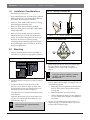
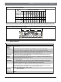
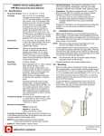
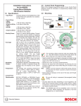
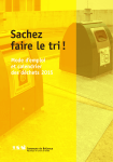
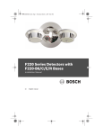
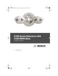
DS9370-BEL
Installation Instructions
EN TriTech Ceiling Mount
PIR/Microwave Intrusion
Detector
DS9370-BEL | Installation Instructions | 1.0
1.0
Installation Considerations
Installation Considerations
•
Not suitable for outdoor use.
•
Never install the detector where the passive infrared
(PIR) or microwave is in constant alarm (LED on).
The LED is off when properly installed.
•
Point away from outside traffic. Microwave energy
passes through non-metallic walls.
•
Point away from direct and indirect sunlight.
•
Point away from glass or other objects that rapidly
change temperature.
•
Point away from rotating machines such as fans.
•
Mount the detector on a solid and vibration-free
surface. Secure drop-ceiling tiles if the area above
the tiles is used as an air return for heating,
ventilating, and air conditioning (HVAC) systems.
•
Figure 2: Opening the DS9370-BEL
1
2
1 - Arrow
2 - Recess between cover and base
Figure 3: Cover Release Tabs
Avoid mounting the detector within 30 cm of any
fluorescent light fixtures.
2.0
1.
Mounting
1
Select a mounting location where an intruder is
most likely to cross the coverage pattern (Figure 1).
1
Figure 1: Coverage Patterns
1 - Release tabs (2)
4. Insert wiring into the rear of the base and through
the center hole or wire entrance for surface
mounting (refer to Items 1 and 2 in Figure 4 on
page 3).
Do not mount the detector to removable
ceiling tiles unless a sandwich is made of
the base, ceiling tile, and a back plate
behind the tile.
2. Mount the detector between 3,7 m and 7,6 m above
the floor.
3. To open the detector, locate the arrow on the
detector’s cover (Item 1 in Figure 2). Insert a flat
head screwdriver in the recess between the cover
and the base and turn (Item 2 in Figure 2).
One side of the cover remains attached to the base
of the detector.
Optional: Remove the cover from the base. Press
the two cover release tabs while lifting the cover
from the base (Figure 3).
Ensure all wiring is unpowered before
inserting wire.
2
5. Firmly mount the base using the mounting holes
(refer to Items 3 and 4 in Figure 4 on page 3) and one
of the following options:
a. Depending on local regulations, mount the base
directly on the surface using anchors, mollies,
or wing nuts.
b.
Mount the detector on an electrical box.
c.
Connect the detector directly to short lengths of
1,27 cm conduit (short enough to avoid detector
movement).
6. Use the curved mounting slots (refer to Item 4 in
Figure 4 on page 3) to rotate the detector up to 60°
to achieve the needed coverage.
Bosch Security Systems, Inc. | 3/11 | 4998141226-02
DS9370-BEL | Installation Instructions | 4.0
4.0
Figure 4: Mounting the Base
Wiring
Wiring
Apply power only after all connections are
made and inspected. Do not coil excess
wiring inside detector.
3
5
If necessary, connect the alarm and tamper contacts to a
safe extra low voltage (SELV) circuit only.
6
6
4
4
Refer to Figure 6 for terminal identification.
3
1
Figure 6: Terminals
-
+
-
+
2
1
2
3
4
5
6
7.
-
Wire entrance or conduit base mounting hole
Wire entrance for surface mounting (2)
Straight mounting holes (2)
Curved mounting slots (2)
Tamper post
Cable ties (2)
To use the ceiling tamper, loosen the tamper post
(Item 5 in Figure 4) by cutting the three tabs and
mount the post to the ceiling using a 0,42 cm screw
(Figure 5).
Figure 5: Mounting the Post to the Ceiling
NO
C
NC
T
T
M
1 2 3 4 5 6 7 8
Terminals 1 (-) and 2 (+): Power limits are 9 VDC to
15 VDC. Use no smaller than 0,8 mm wire pair between
the unit and power source.
Terminals 3 (NO), 4 (C), and 5 (NC): Alarm relay
contacts rated at 125 mA, 28 VDC maximum for DC
resistive loads. Use Terminals 4 and 5 for the
normally-closed circuits. Do not use these terminals
with capacitive or inductive loads.
Terminals 6 (T) and 7 (T): Normally-closed tamper
contacts rated at 28 VDC, 125 mA.
Terminal 8 (M): Memory Mode requires activating a
supply voltage on Terminal 8. Refer to Section 8.0
Memory, Day Mode, Night Mode, and Remote Walk Test on
page 5 for operating and wiring information.
1
2
1 - Tab (3)
2 - 0,42 cm screw (not included)
8. Attach the cover, if removed, and close it.
9. Use the cable ties (Item 6 in Figure 4) for strain relief.
Bosch Security Systems, Inc. | 3/11 | 4998141226-02
3
DS9370-BEL | Installation Instructions | 5.0
5.0
LED Operation
LED Operation
6.0
Walk Test
1: Ensure the LED jumper is set to
ON (refer to Item 2 Figure 7).
2: To avoid false alarm, set the microwave
range to its minimum setting before
starting the Walk Test (refer to Item 3 in
Figure 7).
3: After removing or replacing the cover,
wait 1 min for the detector’s microwave
to settle. Wait at least 5 sec between the
walk testing procedures.
The DS9370-BEL uses a tri-color LED to indicate alarm
and supervision trouble conditions (Table 1).
Table 1:
LED Trouble Conditions
LED
Steady red
Steady yellow
Steady green
Flashing red
Cause
Unit alarm
Microwave activation (Walk Test)
PIR activation (Walk Test)
Warm-up period after power up
Refer to Table 2 for the LED operations and to Table 3
for the PIR sensitivity selections.
Table 2:
LED Operations
Feature
LED
ON/OFF
Pins (refer
to Figure 7)
Setting
ON
OFF
Description
Operates the tri-color LED.
If LED indication is not wanted
after setup and the Walk Tests
are complete, place in the OFF
position.
No jumper across the On or
Off pins disables the LED.
PIR Sensitivity Selection
Setting
Description
Use this setting if more sensitivity is needed.
Recommended setting for most installations.
Tolerates environmental extremes.
LOW**
Wait at least 2 min after power up to start the Walk
Test.
The red LED flashes until the detector stabilizes and
no movement is detected for 2 sec.
Table 3:
HI*
1.
* More sensitive to environmental changes that can cause false
alarms.
** The detector is shipped in Low Sensitivity Mode.
2. Watch the LED as you walk towards the edge of the
pattern (refer to Figure 1 on page 2). The LED lights
at the outside edge of the coverage range. Refer to
Table 4 for the LED indicators.
Table 4:
LED
Green
Yellow
Red
LED Lights
Lights to Identify
PIR pattern.
the microwave pattern.
Microwave and PIR Modes
3. Repeat Step 2 from different directions until you
adequately verify the coverage pattern.
4. If the required microwave coverage is not achieved,
increase the microwave adjustment by slightly
turning it clockwise (Item 3 in Figure 7).
5. Wait 1 min after adjusting the microwave range
before continuing the Walk Test.
Refer to Figure 7
Figure 7: LED ON and OFF Pins and
PIR Sensitivity Selection Pins
Do not adjust the microwave range higher
than needed.
1
HI
7.0
2
•
Microwave: The complete circuit operation of this
subsystem is checked approximately every 4 h.
•
Default: The detector defaults to PIR protection if
the microwave subsystem fails. The detector
indicates an alarm using the green LED only and by
activating the alarm relay.
LOW
ON
3
OFF
MAX
1 - PIR sensitivity
2 - LED ON and OFF
4
Supervision
PIR Signal
Gain
3 - Microwave
Bosch Security Systems, Inc. | 3/11 | 4998141226-02
DS9370-BEL | Installation Instructions | 8.0
8.0
Memory, Day Mode, Night
Mode, and Remote Walk Test
The Memory, Day Mode, Night Mode, and Remote
Walk Test require a supply voltage on Terminal M to
activate. The supply voltage must range from 6 VDC to
18 VDC.
Use the switch (Figure 8) or an external power supply
(Figure 9).
Figure 8: Sample Switch
-
+
-
+
NO
C
NC
T
T
M
Memory, Day Mode, Night Mode, and Remote Walk Test
Refer to Table 4 for the desired action, control voltage,
and LED jumper position.
Table 5:
Tests
Desired Action
Turn on Night Mode
Turn off Night
Mode/Display
Stored Alarm
To RESET Stored
Alarm
Turn on Remote
Walk Test, if off
2
Turn off Remote
Walk Test, if on
1
1 - Power
2 - Memory
8.2
Figure 9: External Power Supply
1
-
Control Voltage
(Terminal M)
ON
(for more than 20 sec)
OFF
(from Night Mode)
LED
Jumper
ON
ON
(for more than 5 sec to
enter Night Mode)
ON
(for more than 5 sec
but less than 20 sec)
ON
(for more than 1 sec
but less than 20 sec)
ON
ON
OFF
OFF
Anti-Vandal Screw
After the cover is closed, secure the entire assembly
using the supplied anti-vandal screw (Figure 10).
+
Figure 10: Anti-vandal Screw
-
+
-
+
NO
C
NC
T
T
M
3
2
1 - Control panel or external DC supply
2 - Power
3 - Memory
•
Control Voltage: +6 VDC to +18 VDC = ON
(Switch Closed); 0 VDC = OFF (Switch Open)
1
1 - Anti-vandal screw
•
Day Mode: Disables the alarm memory and allows
the LED (if activated) to operate normally.
8.3
•
Memory: Activated when the DS9370-BEL is in the
Night Mode. This allows the detector to store an
alarm for display at a later time. Memory Mode
requires the LED jumper to be in the ON position.
At least once each year, verify the detector’s range and
coverage. For continuous daily operation, instruct the
end user to walk through the far end of the coverage
pattern to verify alarm output before arming the system.
•
Night Mode: Enables the alarm memory and
disables the LED operation.
•
Remote Walk Test: Remotely enables LED
operation from Terminal M for walk testing. This
feature is used when LED operation is disabled; the
LED jumper in the OFF position.
Bosch Security Systems, Inc. | 3/11 | 4998141226-02
Maintenance
5
DS9370-BEL | Installation Instructions | 9.0
9.0
Coverage Pattern
Coverage Pattern
Figure 13: Coverage Pattern Masking
Figure 11 shows the typical coverage pattern for 3,7 m
mounting height with optical adjustments set to "I." The
maximum range is available between lens centers, not
directly in front of the lens as might be expected.
1
1
Figure 11: Coverage Areas
1
2
2
3
14
13
3
12
11
10
9
8
7
6
5
4
3
2
2
1
1
0
1
2
1
3
2
1
2
3
4
5
2
3
3
6
7
8
9
10
11
12
13
14
14 13 12 11 10 9 8
1 - 120° mask
7 6 5 4 3 2 1
0 1 2
3 4
5 6 7
Meters
1
2
2 - 90° mask
8 9 10 11 12 13 14
Figure 14: PIR Zones
3
4
1
1 - PIR Area 1
2 - PIR Area 2
9.1
3 - PIR Area 3
4 - Microwave
Coverage Pattern Masking
Mask undesired areas with the supplied set of masks.
The masking kit contains two 120° masks and two 90°
masks designed for the outside of the detector. Place the
masks on the outside of the detector (Figure 12).
Figure 12: Masking Kit
2
MAX
1
2
-
1 - 120° mask
2 - 90° mask
Use the supplied masks to mask 90°, 120°, 180°, 210°
240°, or 330°. Figure 13 shows two examples of coverage
pattern masking.
10.0 Adjusting the Optical Module
The DS9370-BEL PIR zones are divided into three
groups. You can independently adjust each group
vertically for the best coverage within a room
(Figure 14).
6
PIR Signal
Gain
+
NO
C
NC
T
T
M
1 - Only two coverage patterns are shown for clarity.
2 - PIR vertical adjustment knobs (3)
Figure 15 on page 7 shows a sample of the chart located
on the DS9370-BEL. Use this chart to adjust optical
modules based on the detector’s mounting height. The
range shown is the distance from the detector to the
outside edge of the coverage pattern.
In installations where targeted coverage is required for
part of the area, the optical modules must be adjusted
for the correct coverage. In Figure 16 on page 7, the
Bosch Security Systems, Inc. | 3/11 | 4998141226-02
DS9370-BEL | Installation Instructions | 11.0 Specifications
Figure 15: Optical Module Adjustments
AXIMUM
RANGE
FEET (METERS)
MOUNTING HEIGHT FEET (METERS)
8
(2,4)
10
(3)
14
16
12
18
20
22
24
25
15
(3,7) (4,3) (4,6) (4,9) (5,5) (6,1) (6,7) (7,3) (7,6)
10 (3)
C
A
15 (4,6)
G
D
A
A
20 (6,1)
I
G
D
B
A
A
I
F
E
D
C
A
A
30 (9,1)
H
F
E
E
C
B
A
35 (10,7)
I
G
G
F
E
C
B
25 (7,6)
A
A
detector is mounted 3,7 m above the floor. The distance to one wall is 6,1 m and 10,7 m to the opposite wall. Using
Figure 15 the optical module for the 6,1 m range was set to “D” and the optical module for the 10,7 m was set to “I.”
Figure 16: Optical Module Adjustment Sample
(6,1 m)
(10,7 m)
(3,7 m)
For clarity, only two coverage patterns are shown.
11.0 Specifications
Table 5:
Specifications
Dimensions
(H x D)
Coverage
Input Power
Standby
Power
Alarm Relay
Microwave
Frequency
8.9 cm x 17.8 cm
Covers 360° by 15,8 m to 21 m diameter when mounted on 3,7 m to 7,6 m high ceilings.
Covers a 12 m area when mounted at 2,4 m and covers a 15 m area when mounted at 3 m.
The pattern has 69 zones grouped into three sets of 23 zones each. Each set covers 1/3 of the 360°
coverage pattern and has a vertical adjustment for precise pattern alignment.
0 VDC to 15.0 VDC; 19 mA standby, 39 mA in alarm with LEDs enabled, and 39 mA maximum
current. Only use a listed limited power source.
No internal standby battery. 29 mAh required for each hour of standby time needed. Standby power
must be provided by a listed limited power source.
Low and high settings.
-operating Form “C” relay. Contacts rated 125 mA, 28 VDC, 3 W maximum for DC resistive
loads. The contacts transfer on alarm for a period of 4 sec. Some countries require the relay to be
connected to a SELV circuit only. Do not use with capacitive or inductive loads.
Normally-closed (with cover in place) tamper switch. A wall (base) tamper is included. Contacts are
rated at 28 VDC, 125 mA, 3 W maximum. Some countries require the switch to be connected to a
SELV circuit only. Connect the tamper circuit to a 24-hour protection circuit.
Storage and operating range is -40°C to +49°C.
BEL 10,525 GHz
Belgium
Intended Use
Bosch Security Systems, Inc. | 3/11 | 4998141226-02
7
Bosch Security Systems, Inc.
130 Perinton Parkway
Fairport, NY 14450
www.boschsecurity.com
© Bosch Security Systems, Inc. 2011